

Page 1

Multicon
User Manual
Revision: L
2015-06-04
Page 2

Contents
1 Nevion Support 6
2 History 7
3 Product Overview 8
3.1 Introduction 8
3.1.1 Product Offering 9
3.1.2 Licensed Features 9
4 System Architecture 11
4.1 Flashlink 11
4.2 VikinX Sublime 12
4.3 VikinX Modular 13
5 Specifications 16
5.1 Web Interface 16
5.2 Protocols 16
5.2.1 Control Protocols 16
5.2.2 SNMP 17
5.2.3 Configuration Protocol 18
5.2.4 Spread Communication 18
5.3 Performance 18
5.3.1 Number of Flashlink Cards 18
5.3.2 Number of VikinX Devices 18
5.3.3 Number of Web Clients 18
5.3.4 Total Capacity per Multicon System 19
5.4 Front View 19
5.5 Rear View 20
5.6 Hardware Specifications 20
6 Operation 22
6.1 IP Configuration 22
6.1.1 Change from Web Interface 22
6.1.2 Change using Nevion Configurator 23
6.2 System Concept 24
6.2.1 Creating a System from the Web Interface 24
6.2.2 Creating a System using Nevion Configurator 25
6.3 License Keys 27
6.4 Firewall Configuration 28
7 Web Interface 29
Page 3

7.1 General 29
7.2 Alarms Page 30
7.3 Log Page 31
7.4 Config Page 32
7.4.1 User and Access Setup 32
7.4.2 Date and Time 34
7.4.3 Flashlink 35
7.4.4 Debug Terminal 35
7.4.5 SNMP Setup 35
7.4.6 Maintenance 37
7.5 Manuals 37
8 Flashlink Web Interface 38
8.1 Flashlink Sub-system View 38
8.2 Flashlink Module View 38
8.2.1 Information Page 39
8.2.2 Configuration Page 40
8.2.2.1 Card Label 40
8.2.2.2 Advanced Configuration 41
8.2.2.3 Matrix Configuration 41
8.2.2.4 Alarm Configuration 42
8.2.2.5 Passive Modules 43
8.3 Multicon Module View 43
8.4 Flashlink Maintenance 44
8.4.1 Power Supply 44
8.4.2 Rack Labels 45
8.4.3 Stored System Configurations 45
8.4.3.1 Transfer System Configurations 46
8.5 Debug Terminal 46
8.6 Flashlink Firmware Upgrade 47
8.6.1 Transfer Firmware Files to Multicon 48
8.6.2 Micro Controller Upgrade Process 49
8.6.3 FPGA Upgrade Process 50
9 Web Control Interface 51
9.1 List View 51
9.2 Matrix View 53
9.3 Salvo View 54
10 System Overview 56
11 Software Upgrade 57
11.1 Introduction 57
11.1.1 GYDA-SC Upgrade 57
11.1.2 ETH-CON and SYSCON Upgrade 58
Page 4

11.2 Upgrade from GYDA-SC, ETH-CON and SYSCON to Multicon 58
11.3 Upgrade Procedure for Multicon 58
11.3.1 Using Nevion Configurator 58
11.3.2 Using Multicon Web Interface 60
12 Hardware Information 61
12.1 Housing 61
12.2 Status LEDs 62
12.3 How to Access the Module 63
12.4 Card Insertion and Removal 64
12.5 Storage 64
12.5.1 CF card (Mk2 only) 64
12.5.2 MicroSD card (Mk4 only) 65
12.6 Battery (Mk2 only) 65
12.7 Reset Button (Mk2 only) 66
12.8 Dip switches (Mk4 only) 66
12.8.1 Factory default procedure 67
12.9 Flashlink Card Hot Swap 67
12.10 Back Plane Connectors 68
12.10.1 Hardware revision 2 68
12.10.2 Hardware revision 4 69
12.11 GPIO 70
12.11.1 Connections (mk2) 70
12.11.2 Connections (mk4) 70
12.12 Monitor Flashlink Power Supplies (mk2) 71
12.13 Serial Connectivity 71
12.13.1 Maximum Cable Length (RS-232) 72
12.14 Ethernet Connectivity 72
12.14.1 Ethernet connections on Mk4 72
12.15 External RS422 Flashlink Connectivity 72
A Protocol Specifications 74
A.1 Modular Router Protocol (MRP) 74
A.2 NCB Sublime/Compact 74
A.3 SNMP 74
A.4 Snell Pro-bel SW-P-02 74
A.5 Leitch Pass-Through 75
A.6 Triton 77
A.7 Thomson/Grass Valley Native 77
B General Environmental Requirements for Nevion Equipment 80
C Product Warranty 81
Page 5

D Materials Declaration and Recycling Information 82
D.1 Materials Declaration 82
D.2 Recycling information 82
E EC Declaration of Conformity 83
Page 6

Nevion Support 6
1 Nevion Support
Nevion Europe
P.O. Box 1020
3204 Sandefjord, Norway
Support phone 1: +47 33 48 99 97
Support phone 2: +47 90 60 99 99
Nevion USA
1600 Emerson Avenue
Oxnard, CA 93033, USA
Toll free North America: (866) 515-0811
Outside North America: +1 (805) 247-8560
E-mail: support@nevion.com
See
http://www.nevion.com/support/ for service hours for customer support globally.
ID: man-multicon Multicon Manual Rev. L
Page 7

2 History
Revision Date Author Comments
L 2015-06-04 JGS Updated dip switch info and factory reset procedure
K 2015-01-09 JGS/JIH Updated with info about hardware version 4
J 2013-10-31 JIH Updated for release 4.0
H 2013-09-03 JGS/JIH Added new protocol info for release 3.8
G 2012-12-17 JGS Updated revision info
6 2012-10-01 JIH Info about external RJ45 connection
5 2012-09-07 JGS Updated text describing upgrade possibilities.
4 2011-04-27 JIH Added performance data in Chapter 3.6.
3 2011-01-03 JIH Added alert box in Chapter 2.2.
2 2010-09-15 JIH Updated GYDA user management (Chapter 5.5.1).
1 2009-12-30 JIH Consolidated all manuals
0 2009-07-02 JIH First official release
History 7
ID: man-multicon Multicon Manual Rev. L
Page 8

Product Overview 8
3 Product Overview
3.1 Introduction
The Multicon product provides fully integrated state-of-the-art element management and system
control capabilities for Flashlink and VikinX systems. Multicon supports a wide range of applications ranging from optical network monitoring and configuration to router control.
The Multicon product provides element managementvand system control capabilities for Flashlink and VikinX systems. The software may be licensed to supportvdifferent applications and is
available in different product packages to support the main applications.
Multicon includes interfaces for web-based monitoring andvcontrol, hardware and software control panels, automation systems and SNMP-based network management systems. The software
also supports control of third-party devices using industry standard protocols.
The Multicon software is running on a dedicated hardware card that may be installed in Flashlink, Flashcase, N-BOX or VikinX Modular frames. Multicon is typically installed in an N-BOX to
support Flashlink Compact and Sublime devices.
Multicon is the second generation system controller from Nevion replacing the former GYDA-SC,
ETH-CON and Syscon products. Multicon is based on an open and distributed architecture and
provides one platform to monitor and control both Flashlink and VikinX products. These features
and a powerful third party plug-in interface allow for full control of the entire video transport
chain.
The latest range of Flashlink SP&D cards have a large number of parameters that may require modification in a production environment. Multicon provides the solution for easy access to control
SP&D parameters from control panels or automation systems. This new feature allows the user to
modify SP&D parameters like scaling, pan and zoom from control panels during operation of the
card.
The following key features are provided by Multicon:
• User-friendly web GUI for monitoring, configuration and control of Flashlink and VikinX
• Support for up to 80 Flashlink cards
− Status information and card configuration
− Hot-swap of cards
− Remote firmware upgrade
• Support for VikinX Sublime, Compact and Modular
− Level control, virtual routing and salvos
− System with multiple controllers
• Integration with hardware and software control panels
• Alarm management and forwarding
ID: man-multicon Multicon Manual Rev. L
Page 9

Product Overview 9
• SNMP support for monitoring and configuration
• Third-party router integration (Leitch, GVG and Pro-bel)
3.1.1 Product Offering
Main product based on Multicon hardware revision 4:
Sales product Description Hardware
MCON-HW-MK4 Main board and backplane only
Requires software licenses
Main product based on Multicon hardware revision 2:
Sales product Description Hardware
Multicon VX-MOD Web, Control Panel and SNMP interface for
- Modular router (64/128/256)
- 32 Sublime/Compact routers
Used for Flashlink and Sublime systems
For use with VikinX Modular only
3.1.2 Licensed Features
The Multicon software is the same for all products but the features are controlled by licenses. The
table below shows the licenses included with each product offering. It is possible to add additional
features by adding licenses to a Multicon controller.
Licenses for Multicon hardware revision 4:
Sales product Description
MCON-SW-FL-10 Multicon license for 10 Flashlink cards (1 frame)
MCON-SW-FL-80 Multicon license for 80 Flashlink cards (8 frames)
MCON-SW-VX-SL Multicon license for Sublime routers
MCON-SW-WCTRL Multicon license for web-based router control
MCON-SW-3PP Multicon license for third-party protocols
Licenses for Multicon hardware revision 2:
Sales product/
Licensed features
Multicon OPT-GYDA-ONE:
Flashlink support for one (1) frame
Multicon
GYDA-ONE
Included Included Option Option
Multicon
GYDA
Multicon
VX-SLC
Multicon
VX-MOD
ID: man-multicon Multicon Manual Rev. L
Page 10

Product Overview 10
Sales product/
Licensed features
Multicon OPT-GYDA:
Flashlink support for up to eight (8) frames
Multicon OPT-VX-SLC:
VikinX Sublime/Compact support
Multicon OPT-VX-MOD:
VikinX Modular support
Multicon OPT-TRITON:
Triton protocol support
Multicon OPT-PROBEL:
Pro-bel SW-P-02 protocol
Multicon OPT-LEITCH:
Leitch pass-through protocol
Multicon OPT-GVG:
Grass Valley/Thomson protocol support
Multicon OPT-WC:
Web control interface
Multicon OPT-3PP:
Third-party plug-in support
Multicon
GYDA-ONE
Option Included Option Option
Included Included Included Included
Option Option Option Included
Included Included Included Included
Option Option Option Included
Option Option Option Option
Option Option Option Option
Option Option Option Option
Option Option Option Option
Multicon
GYDA
Multicon
VX-SLC
Multicon
VX-MOD
ID: man-multicon Multicon Manual Rev. L
Page 11
System Architecture 11
4 System Architecture
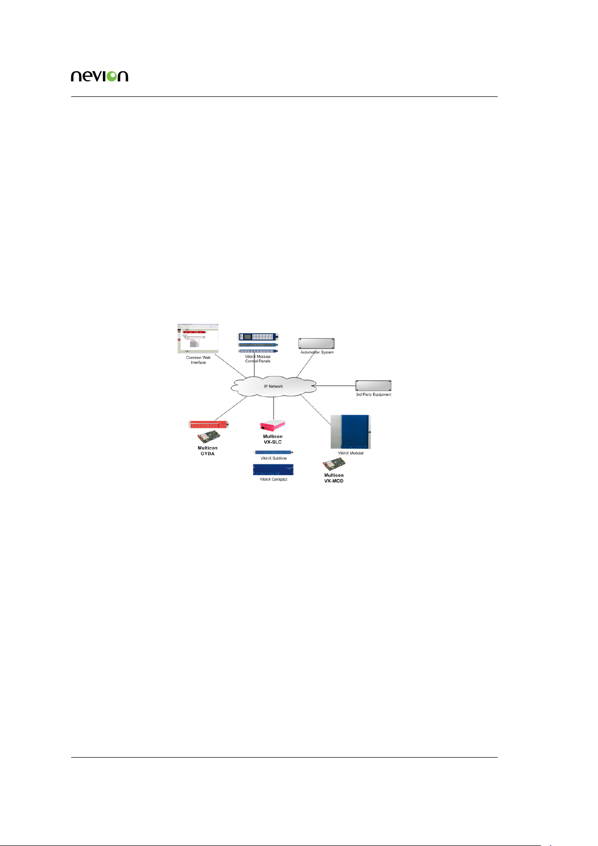
Figure 4.1 below illustrates the Multicon architecture. The Multicon controllers may be fitted ei-
ther in Flashlink frames, N-BOX housing or in the VikinX Modular frame.
All Multicon controllers provide a Web interface on HTTP port 80 and a Control Panel interface on
MRP port 4381. The controllers also exchange status information using the TCP/IP based MBUS
protocol (for internal use between controllers only and not visible externally).
Using the third-party SDK it is also possible to integrate with other TCP/IP hosts and clients.
Host devices are typically automation systems or third-party control systems that shall control
Multicon while client devices shall be controlled by Multicon.
Each Multicon controller provides two RS-232/RS-422 serial ports for connection of VikinX Compact routers or third-party devices that communication over serial.
Figure 4.1 Multicon system architecture
Note that in the figure Multicon GYDA is the product for Flashlink monitoring and control, Multicon VX-SLC is the product for VikinX Sublime and Multicon VX-MOD is the product for VikinX
Modular. With hardware revision 4 of Multion, there are no longer separate products for Multicon
GYDA and VX-SLC, but the same Multicon product may be licensed to support either Flashlink,
VikinX Sulime or both.
4.1 Flashlink
For Flashlink it is necessary to have one Multicon in each Flashlink sub-system which may consist
of up to eight (8) frames. Note that if there is a separate license that supports only one (1) frame.
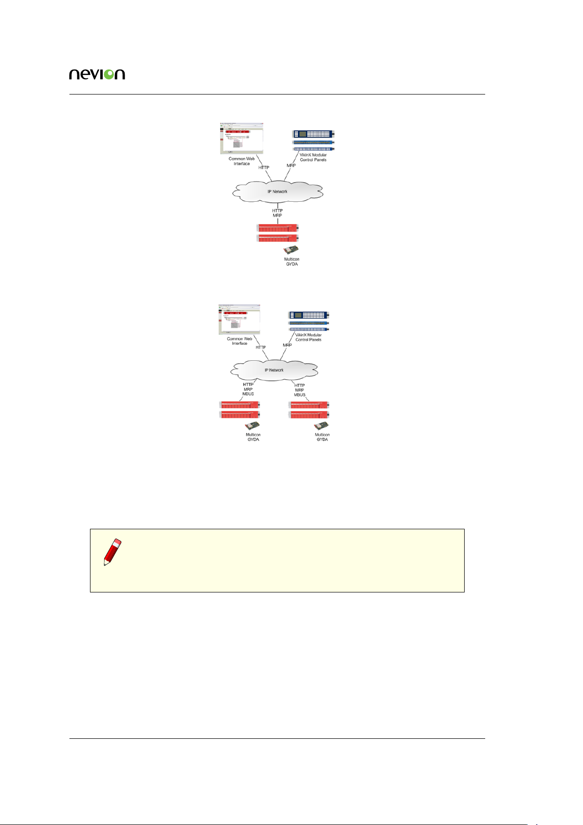
Figure 4.2 shows how you can interface with one Flashlink sub-system using the Web interface
and Control Panels. The Web interface uses the W3C standard HTTP protocol and the Control
Panels use the Nevion MRP protocol.
It is possible to combine several Flashlink sub-systems into one Multicon system as illustrated
in Figure 4.3. In this simple example you can use the same Web interface and Control Panels to
manage modules in both Flashlink sub-systems.
ID: man-multicon Multicon Manual Rev. L
Page 12
System Architecture 12
Figure 4.2 Multicon for one Flashlink
sub-system
Figure 4.3 Multicon for multiple Flashlink sub-systems
The Multicon controllers communicate internally over the Nevion MBUS protocol to exchange
status information and perform settings across physical controllers (for internal use between controllers only and not visible externally).
Note: As a design rule it is recommended to keep the Multicon systems
as small as possible, i.e. place only equipment that needs to be managed
from the same Web interface and Control Panels into the same Multicon
system.
4.2 VikinX Sublime
Multicon is used to control VikinX Sublime, Compact and 3rd party routers. Multicon is also used
as an interface between VikinX Sublime/Compact routers and Control Panels.
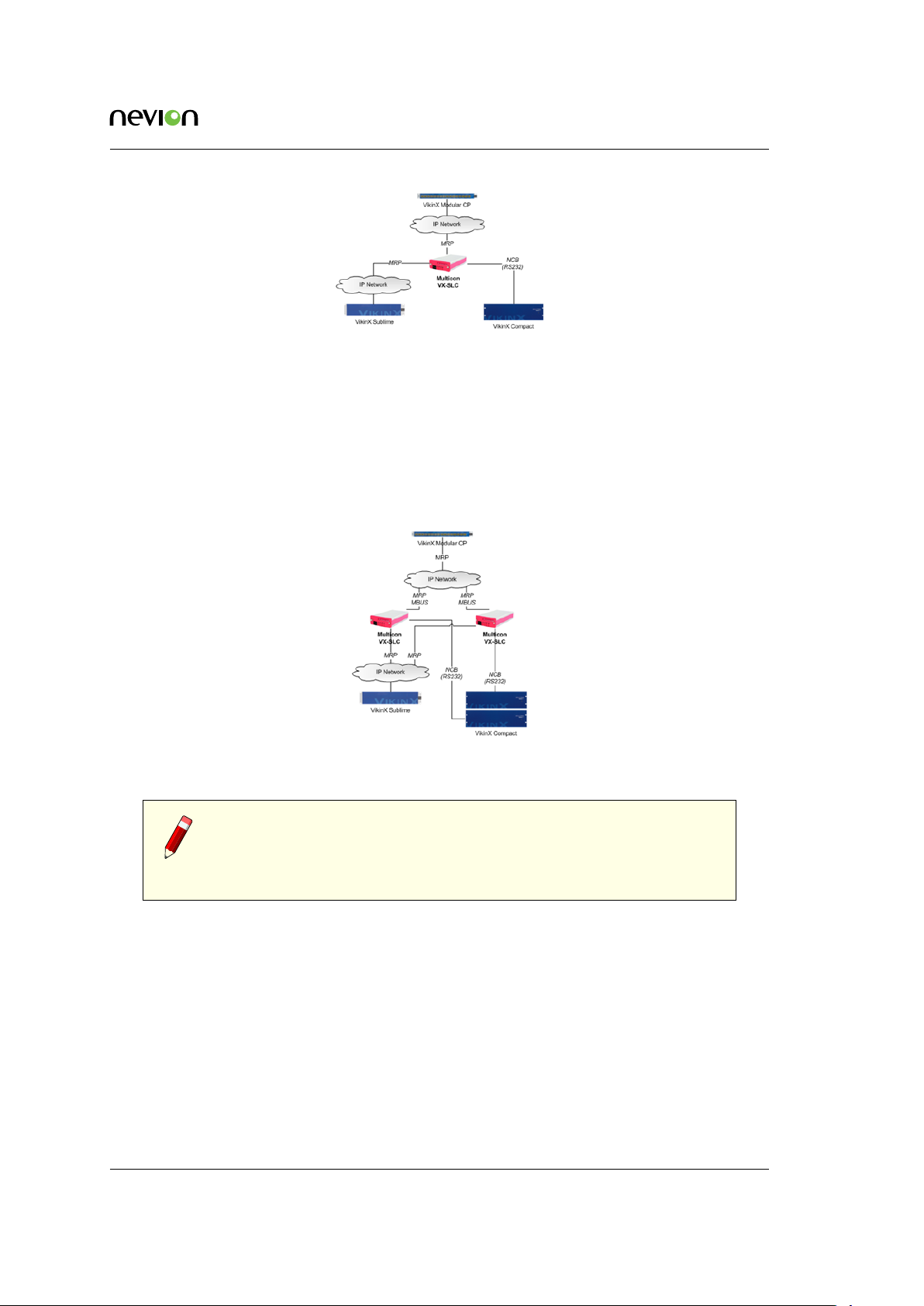
Figure 4.4 shows how to use Multicon to control a VikinX Sublime router over TCP/IP and a
VikinX Compact router over the Network Control Bus (NCB) via a RS-232 connection to the router.
ID: man-multicon Multicon Manual Rev. L
Page 13
System Architecture 13
Figure 4.4 Multicon for VikinX Sublime and Compact
Figure 4.5 shows how to deploy redundant controllers for control of a VikinX Sublime and Com-
pact router. The two Multicon controllers communicate via an internal MBUS protocol. If one
controller fails the other controller will take over as main controller for the routers. The control
panels will also switch over to the other controller.
The Multicon controllers communicate internally over the Nevion MBUS protocol to exchange
status information and perform settings across physical controllers.
Figure 4.5 Redundant Multicon for
VikinX Sublime and Compact
Note: Sublime control panels can only have one connection to a controller,
which means that it is not possible to use Sublime control panels with two
redundant Multicon controllers. If redundancy is required it is necessary
to use VikinX Modular control panels instead.
Figure 4.6 shows how to control a Pro-bel router and a Triton router from a Multicon controller.
Multicon communicates with the routers using SW-P-02 serial line protocol and Triton Protocol.
4.3 VikinX Modular
Multicon VX-MOD is used to control VikinX Modular routers but also comes with support for
VikinX Sublime, Sublime Compact and Compact routers. In addition, the product may be controlled by or control devices using the Pro-bel SW-P-02 protocol. Optionally it is also possible to
extend the protocol support with other third-party protocols.
ID: man-multicon Multicon Manual Rev. L
Page 14

System Architecture 14
Figure 4.6 Multicon control
of third-party routers
Figure 4.7 Multicon VX-MOD for VikinX Modular, Sublime and third-party control
The following examples show possible ways to use Multicon VX-MOD in combination with VikinX,
Flashlink and Pro-bel routers.
Figure 4.7 shows how to use Multicon VX-MOD together with VikinX Sublime, Compact and Pro-
bel routers. The Sublime router is connected via TCP/IP (Modular Router Protocol), while the
Compact and Pro-bel routers are connected via serial line interface.
Figure 4.8 Multicon for VikinX Modular
and Sublime control in a system with a Multicon for Flashlink control
ID: man-multicon Multicon Manual Rev. L
Page 15
System Architecture 15
Figure 4.8 shows how to use Multicon VX-MOD together with VikinX Sublime and a Flashlink
system with Multicon GYDA. The Sublime router is connected via TCP/IP using the Modular
Router Protocol, while Multicon for Flashlink (in the Flashlink frame) is connected via TCP/IP
using the MBUS protocol between Multicon controllers.
The two redundant Multicon controllers in the Modular frame have to communicate internally to
exchange state information using the MBUS protocol over the external IP network (for internal use
between controllers only and not visible externally).
Note: Redundant Multicon controllers always have to be reachable over
an external IP network.
ID: man-multicon Multicon Manual Rev. L
Page 16
Specifications 16
5 Specifications
5.1 Web Interface
The Multicon web interface is supported for the following browser versions:
• Firefox version 25 or higher
• Internet Explorer 10 or higher
• Chrome version 30 or higher
Note: Multicon 4.0 and newer uses web socket technology that requires
an updated browser version.
5.2 Protocols
5.2.1 Control Protocols
Multicon supports various control protocols for northbound communication (referred to as host
protocols) and southbound communication (referred to as client protocols). Host protocols are
typically used for integrating with control panels and external systems like automation. Client
protocols are used for integrating with devices such as routers and terminal gear.
Multicon uses the Modular Router Protocol (MRP) over TCP/IP as its default protocol for northbound (host) and southbound (client) access. The protocol is open for third-party integration and
the specification is available as a separate manual document.
Supported northbound (host) protocols:
• MRP (IP)
• NCB Compact (serial)
• NCB Sublime (serial)
• SNMP (IP)
• Thomson/Grass Valley Native (IP and serial)
• Leitch PassThru (IP and serial)
• Pro-Bel SW-P-02 (IP and serial)
• Triton (serial)
Supported southbound (client) protocols:
ID: man-multicon Multicon Manual Rev. L
Page 17
Specifications 17
• MRP (IP)
• NCB Compact (Serial)
• NCB Sublime (Serial)
• Thomson/Grass Valley Native (IP and serial)
• Leitch PassThru (IP and serial)
• Pro-Bel SW-P-02 (IP and serial)
• Triton (serial)
This list is valid for Multicon firmware 3.8.0 (or newer). To configure a Multicon system with these
protocols also requires Nevion Configurator 4.4.0 (or newer).
Further information concerning the level of support for each protocol is provided in Appendix A.
Note: Note that the availability of these protocols depends on the licensing
of the Multicon product.
5.2.2 SNMP
Multicon supports SNMP version 1, 2c or 3 over UDP, following SMI version 2.0 according to
relevant RFCs.
RFC1157
Case, J., M. Fedor, M. Schoffstall and J. Davin, “The Simple Network Management Protocol”,
STD 15, RFC 1157, May 1990.
RFC2578
McCloghrie, K., Perkins, D. and J. Schoenwaelder, “Structure of Management Information
Version 2 (SMIv2)”, STD 58, RFC 2578, April 1999.
RFC1901
The SNMPv2 Working Group, Case, J., McCloghrie, K., Rose, M. and S. Waldbusser, “Introduction to Community-based SNMPv2”, RFC 1901, January 1996.
RFC2574
Blumenthal, U. and B. Wijnen, “The User-Based Security Model for Version 3 of the Simple
Network Management Protocol (SNMPv3)”, RFC 2574, April 1999.
The following security features are supported:
• User defined community strings (v1 or v2c)
• User based Security Model (v3 only)
• Possible to turn off v1/v2c support.
ID: man-multicon Multicon Manual Rev. L
Page 18

Specifications 18
All alarms are sent as SNMP traps with user selectable filtering.
5.2.3 Configuration Protocol
Multicon uses Device Configuration Protocol (Nevion proprietary) over TCP/IP for setup of the
system. The protocol is only used internally between the Nevion Configurator and Multicon.
5.2.4 Spread Communication
This product uses software developed by Spread Concepts LLC for use in the Spread toolkit. For
more information about Spread see http://www.spread.org.
The Spread interface is used for internal communication between Multicon controllers and provides a highly reliable communication mechanism.
5.3 Performance
5.3.1 Number of Flashlink Cards
The following number of Flashlink cards are supported per Multicon card:
• 10 Flashlink cards maximum with single-frame license
• 80 Flashlink cards maximum with multi-frame license
5.3.2 Number of VikinX Devices
The following number of VikinX devices (routers and control panels) are supported per Multicon
card:
• Total of 32 devices (routers and control panels) when the Multicon card is NOT used for
Flashlink
• Total of 8 devices (routers and control panels) when the Multicon card is also used for
Flashlink
5.3.3 Number of Web Clients
The following number of web clients are supported per Multicon card:
• Total of 10 web clients when the Multicon card is NOT used for Flashlink
• Total of 5 web clients when the Multicon card is also used for Flashlink
ID: man-multicon Multicon Manual Rev. L
Page 19
Specifications 19
5.3.4 Total Capacity per Multicon System
The following specifies total capacity per Multicon system:
• Total number of levels (video and audio) in a system should be less than 200
• Total number of control panels in a system should be less than 64
• Total number of crosspoints (in all levels) in a system should be less than 5000
• Total number of virtual routers in a system should be less than 10 with a maximum of 256
crosspoints in each virtual router
• Total number of salvos in a system should be less than 100 with a maxium of 256 settings
in each salvo
Please contact Nevion Support to discuss system configuration options if your planned system
exceeds the total capacity above.
5.4 Front View
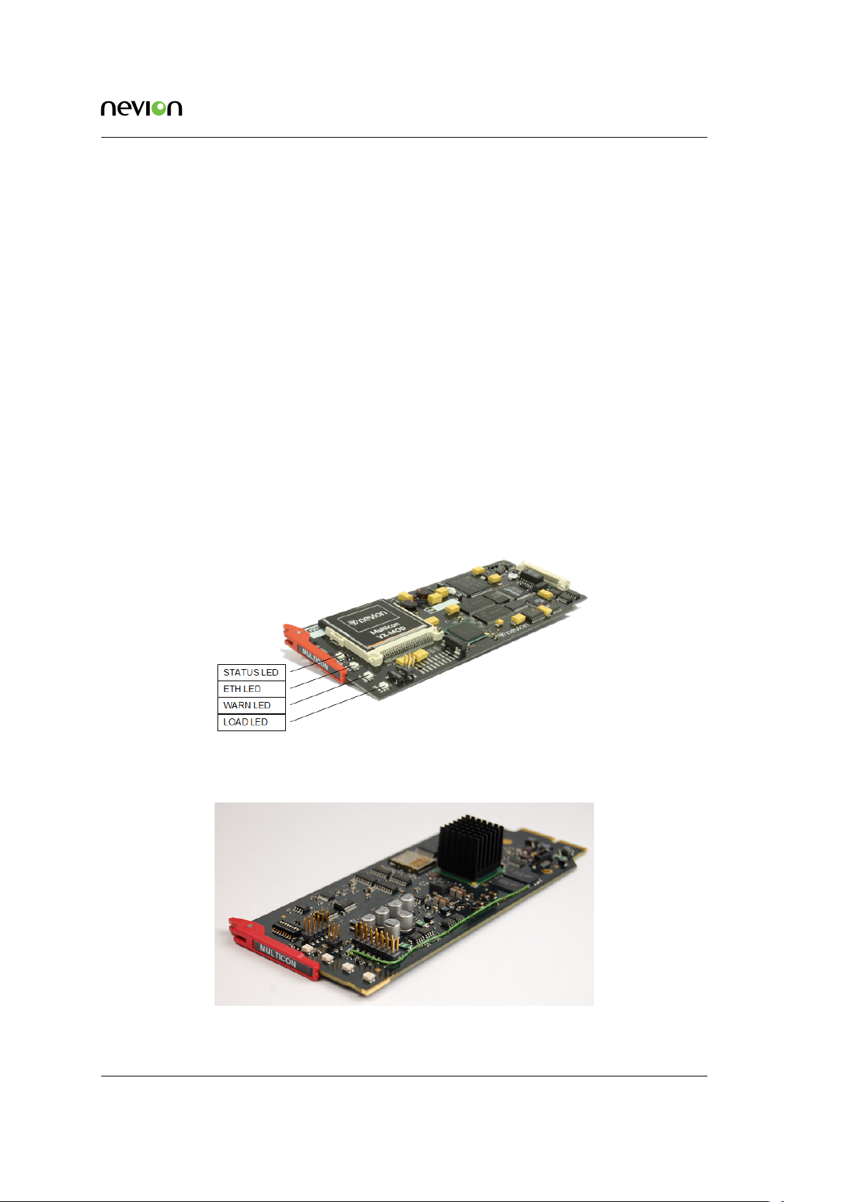
Figure 5.1 shows the front-view of Multicon Mk2.
Figure 5.1 Front-view Mk2
Figure 5.2 shows the front-view of Multicon Mk4.
Figure 5.2 Front-view Mk4
ID: man-multicon Multicon Manual Rev. L
Page 20
Specifications 20
5.5 Rear View
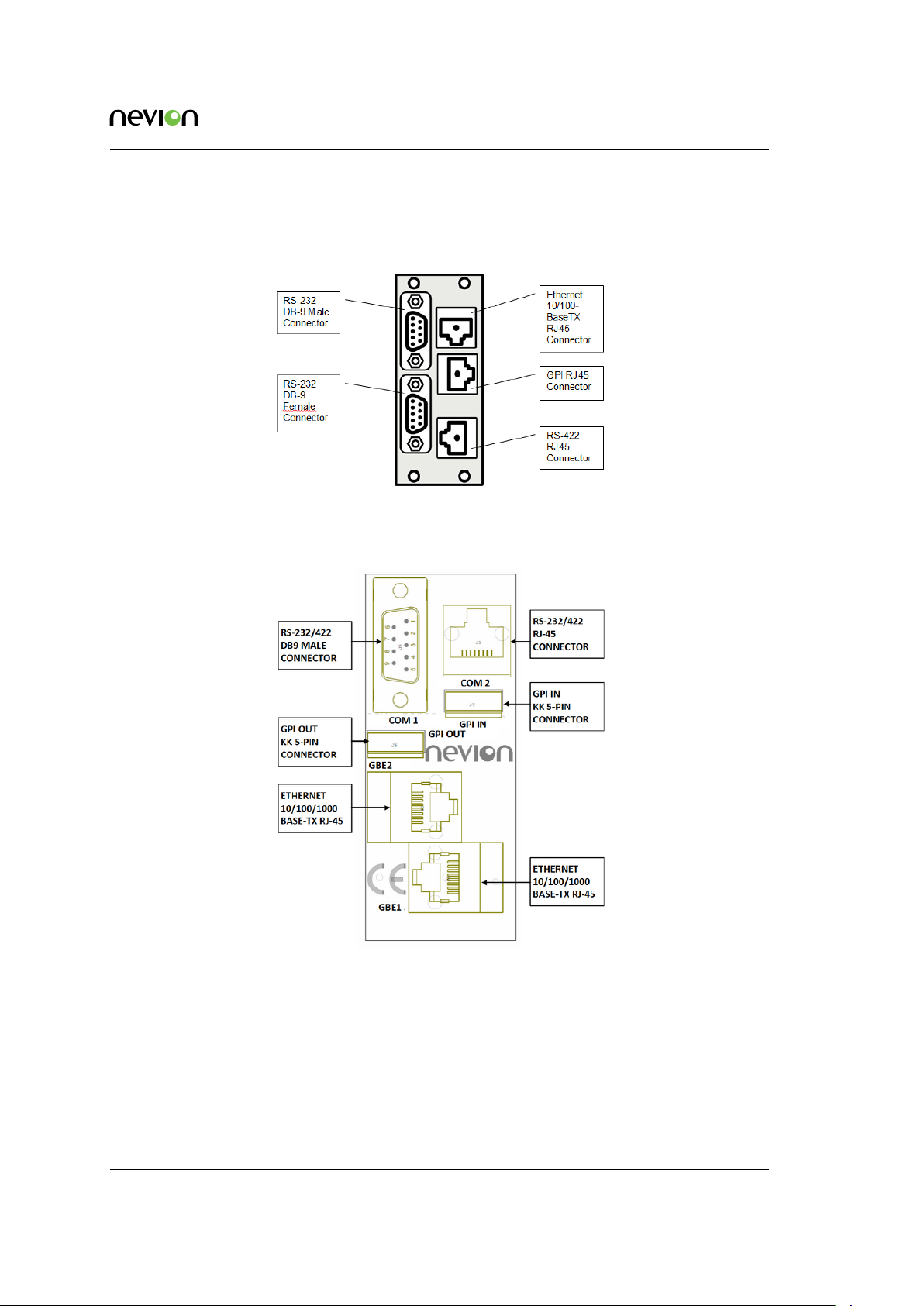
Figure 5.3 shows the rear-view connectors and their function for Multicon Mk2.
Figure 5.3 Rear-view Mk2
Figure 5.4 shows the rear-view connectors and their function for Multicon Mk4.
Figure 5.4 Rear-view Mk4
5.6 Hardware Specifications
The following specifications apply for controller hardware versions 2 and 4.
ID: man-multicon Multicon Manual Rev. L
Page 21
Specifications 21
Component Version 2 (Mk2) Version 4 (Mk4)
CPU 400MHz StrongARM PXA255 533MHz DualCore PowerPC e500v2 P1025
Memory 64MB SDRAM
8MB on-board Flash
Compact Flash card
RS-232/
RS-422
Ethernet 1 x 10BaseT/100BaseTX
Power +5V DC, 3W +5V DC, 7W
3 x COM ports
Connectors DB9M,DB9F,RJ-45
IBM PC TIA-574 (RS-232)
SMPTE 207M (RS-422)
8P8C TIA-561 (RJ-45)
Full duplex
512MB 32bit DDR3 SDRAM
2MB on-board Flash
MicroSD card
2 x COM ports
Connectors DB9M, RJ-45
IBM PC TIA-574 (RS-232)
SMPTE 207M (RS-422)
8P8C TIA-561 (RJ-45)
2 x 10BaseT/100BaseTX/1000BaseTX
Full duplex
Note: Multicon requires controller hardware version 2 (Mk2) or version 4
(Mk4). It cannot run on controller hardware version 1 (Mk1).
ID: man-multicon Multicon Manual Rev. L
Page 22
Operation 22
6 Operation
This chapter describes operational preparations that are required before the Multicon controller
may be used to monitor and control Flashlink, VikinX Sublime or Modular sub-systems. The
preparations described here are common for all Multicon controllers and involves use of the Nevion
Configurator.
This is not a complete guide to setting up Multicon systems using the Nevion Configurator, but
limited to the preparations required to start using your Multicon controller. Please refer to the
Nevion Configurator online help for more detailed information about configuring Multicon systems.
6.1 IP Configuration
6.1.1 Change from Web Interface
Multicon 4.0 and newer supports changing the IP address from the web interface. This will also
automatically create a system as described in Section 6.2 and provides an easier way to get started
using the Multicon controller.
To change the IP address from the web interface perform the following steps:
1. Connect a laptop directly to the Ethernet port of the Multicon controller.
2. Configure the laptop to use the IP address 10.0.0.12 and netmask 255.255.255.0.
3. Open a supported web browser and go to http://10.0.0.11.
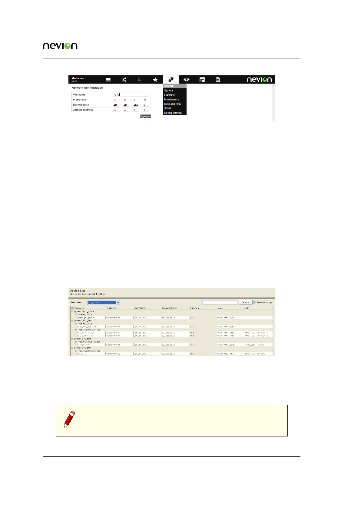
4. Select the Config tab and click on Network which presents the page shown in Figure 6.1.
5. Set the hostname as required.
6. Set the IP address, netmask and default gateway to match the network configuration.
7. Click on Update.
The default IP address 10.0.0.11 aboveis set for all new cards delivered by Nevion. If the IP address
has been changed previously for the card, then this address will have to be used. If the IP address
is not known then the Nevion Configurator may still be used to set a new IP address.
Note: Changing the network settings will trigger a reboot of the Multicon
controller.
Note: Changing IP address from the web interface is only possible if the
controller is not yet added to a system or is in a system with only one
controller. If multiple controllers are present in the system, the Nevion
Configurator must be used to set a new IP address.
ID: man-multicon Multicon Manual Rev. L
Page 23
Operation 23
Figure 6.1 Web interface network settings
6.1.2 Change using Nevion Configurator
This section describes how to change the IP address of the Multicon controller using the Nevion
Configurator. The same procedure is applicable for changing IP configuration for control panels
and routers. The IP configuration procedure is described in detail below:
1. Open the Nevion Configurator.
2. Select a system to open or click cancel. Note that it is not necessary to open a system to
perform IP configuration.
3. Go to Tools -> IP settings from the menu bar.
4. Select the appropriate filter from the drop down.
5. Current system only will only show devices in the currently open system.
6. All systems will show all devices detected by the Nevion Configurator grouped per system.
7. Device types will show all devices grouped by device type.
Figure 6.2 Nevion Configurator device list
1. Select the device you want to modify the IP configuration for and enter correct IP configuration settings.
2. Click OK at the bottom of the window.
Note: The IP configuration for the Multicon controllers MUST be done
using the Nevion Configurator. It is NOT possible to modify IP address
settings by modifying files on the CF-card directly.
ID: man-multicon Multicon Manual Rev. L
Page 24
Operation 24
6.2 System Concept
It is necessary to include all Multicon controllers in a system using the Nevion Configurator. A
system is a collection of devices and user configuration. It is the user that defines the system and
how it’s configured.
Multicon is the system controller handling the system and all communication between devices in
the system.
In a system there can be control panels (Modular or Sublime), router sub-systems (Modular, Sublime or 3rd party) and Flashlink sub-systems.
The following guidelines apply for configuring systems:
• All devices that needs to be controlled together must be included in the same system
• Devices that do not need to be controlled together should be included in separate systems
• Typically it makes sense to define one system per production studio or outside broadcast
van
• For Flashlink fiber transport it may be preferable to define one system per site to reduce
inter-site traffic
Note: All Multicon controllers are shipped without a default system. Before using the Multicon the IP address have to be set correctly and it has
to be added to a system.
6.2.1 Creating a System from the Web Interface
Multicon 4.0 and newer supports a simplified process for creating systems that consists of only
Flashlink and Sublime devices.
When configuring network settings from the web interface, a system is automatically created by
the Multicon controller. This system only includes the controller itself. For Flashlink systems no
additional steps is required.
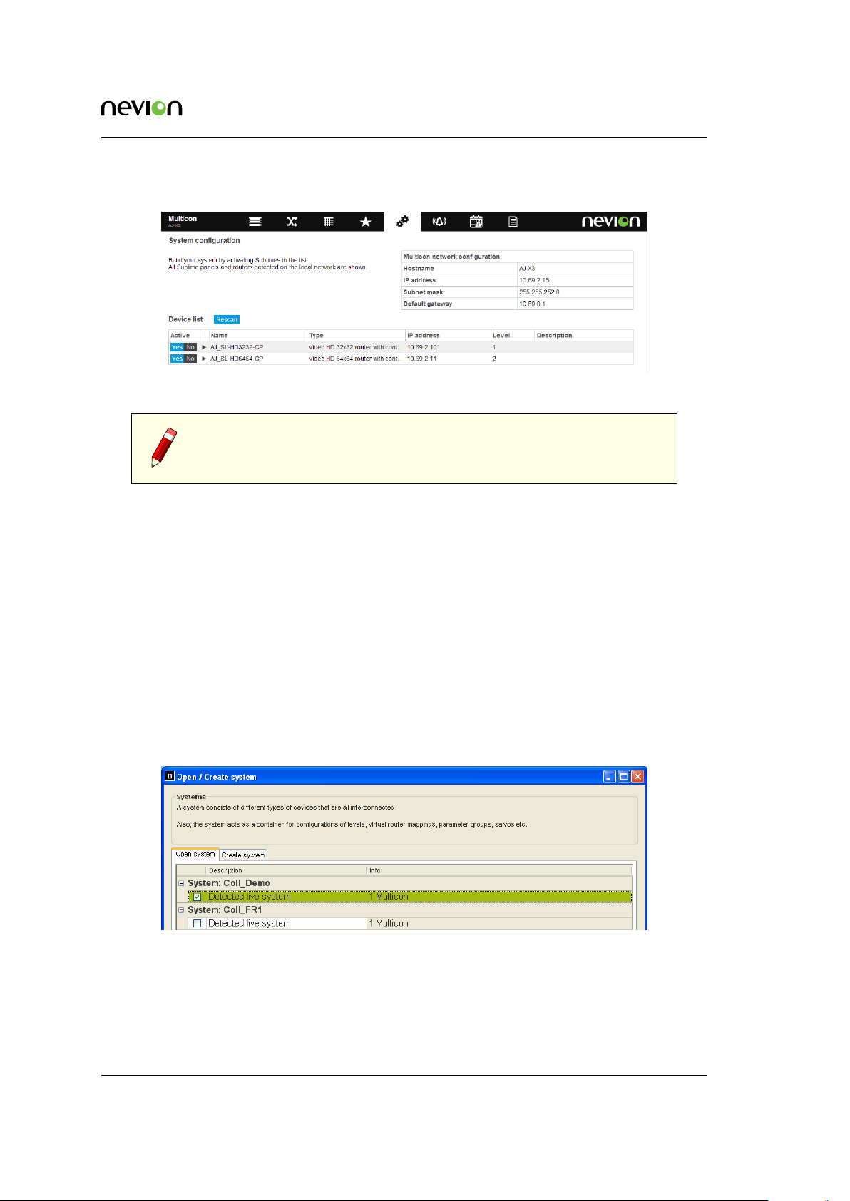
It is possible to add Sublime devices to the automatically created system using the following steps:
1. Make sure that IP address settings have been performed correctly for the controller.
2. Using a supported web browser hover over the Config tab and select System.
3. Click on rescan to search for Sublime devices on the local area network (to add remote
devices please refer to the Nevion Configurator).
4. A list of available Sublime devices is presented (that is not previously allocated to another
system).
5. It is possible to change the Name, IP Address and Level for each device by hovering over
the field and clicking the Edit button.
6. Select Yes in the Active column to add a device to the system.
ID: man-multicon Multicon Manual Rev. L
Page 25
Operation 25
Figure 6.3 illustrates the user interface for configuring a system using the Multicon web interface.
Figure 6.3 Web interface system settings
Note: Only Sublime devices may be added to a system from the Web
interface. In addition, cascaded devices are not supported.
6.2.2 Creating a System using Nevion Configurator
To view the default system configuration you need to do the following:
1. Make sure that the Nevion Configurator is installed on your PC and that the PC is attached to the same subnet where the equipment resides. This is required since the Nevion
Configurator uses UDP broadcast to detect systems and devices.
2. If Nevion Configurator is not installed, download and install the application from http:
//www.nevion.com/support.
3. Open Nevion Configurator. A dialog showing detected systems will be shown.
4. Select the system you would like to open, the default system is called System1. Click OK.
Figure 6.4 Nevion Configurator open system
1. The figure below shows the default system for a Multicon that is controlling a Flashlink
sub-system.
ID: man-multicon Multicon Manual Rev. L
Page 26

Operation 26
Figure 6.5 Nevion Configurator system overview
If your Multicon controller is not assigned to a system:
1. Open Nevion Configurator. When the Open / create system dialog appears, click the
Create system tab.
Figure 6.6 Nevion Configurator create system
1. Enter a System name and optionally a System description. Click OK.
2. A new empty system is created. Your Multicon controller should be listed under Unconfigured devices on the left hand side.
3. Select the Multicon controller you want to include in the system and drag it into the system overview.
1. Click upload from the menu bar. The Multicon controller is added now added as the
only device in the system.
ID: man-multicon Multicon Manual Rev. L
Page 27

Operation 27
Note: Please consult the Nevion Configurator online help for more detailed
information about configuration of systems for VikinX routers and control
panels.
6.3 License Keys
All Multicon controllers are running the same software and it is the installed license keys that
control the available features. It is different license keys that make the controller a Multicon for
Flashlink and/or VikinX.
The Nevion Configurator allows you to view the installed license keys and add additional license
keys to enable new features.
To manage the installed license keys you need to do the following:
1. Open Nevion Configurator.
2. Select a system to open or click cancel. Note it is not necessary to open a system to manage
license keys.
3. Go to Tools -> Product Key Manager from the menu. The following page will appear.
Figure 6.7 Nevion Configurator product keys
1. Click on a Multicon controller to view the installed license keys.
2. Click New or Import from File to add a new license key for this controller.
3. Click OK.
Note: It is not possible to add license keys to a Multicon controller that
is not included in a system using the Nevion Configurator. Make sure that
the controller is added to a system before attempting to modify license
keys.
ID: man-multicon Multicon Manual Rev. L
Page 28

Operation 28
6.4 Firewall Configuration
In order for multiple Multicon controllers and the Nevion Configurator to work, a few select ports
must be open. These are described below.
Port 80 is required for communication between the Multicon Web interface and the Multicon controller and must always be open.
Port 2836, 2837 and 2838 are required for communication between Multicon controllers that are
configured in the same system.
Port 3972 is required for communication between the Nevion Configurator and Multicon controllers, control panels and routers in the system.
The Nevion Configurator uses broadcast to detect devices and requires that all devices in the system are on the same IP sub-net.
Port 4381 is required for communication between Multicon controllers and control panels and
routers in the system.
Port Type Description
80 TCP HTTP traffic from UI to Multicon
(Web browser -> Multicon controller)
8080 TCP Web socket traffic from UI to Multicon
(Web browser -> Multicon controller)
2836 TCP + UDP Primary port for Spread distribution mechanism
(Multicon -> Multicon)
2837 TCP + UDP Aux port for Spread
(Multicon -> Multicon)
2838 TCP + UDP Aux port for Spread
(Multicon -> Multicon)
3972 TCP + UDP Nevion Configurator to device communication
(Nevion Configurator -> Multicon, Control Panel, Sublime routers)
4381 TCP MRP connections
(Control Panel -> Multicon)
(Multicon -> Sublime routers)
In addition, any ports used by third party protocol must be open.
ID: man-multicon Multicon Manual Rev. L
Page 29

Web Interface 29
7 Web Interface
Multicon includes a common web interface for Flashlink and VikinX monitoring and control.
Common features are described in this chapter while the Flashlink specific features are described
the chapter Flashlink web interface.
7.1 General
There are five common views in the Multicon Web interface. Each has its own menu tab at the top,
and will be highlighted when selected.
• Frames (Optional, for monitoring and configuration of Flashlink cards or Sublime X2)
• Config (Multicon configuration settings, e.g. user access, SNMP, firmware upgrade etc)
• Alarms (All alarms within the system)
• Log (Shows last 4000 events after power up)
• Manuals (All user manuals in PDF-format)
In addition, there are optional views for web control. These are described in the Web Control
Interface chapter.
Figure 7.1 Multicon web interface menu bar
ID: man-multicon Multicon Manual Rev. L
Page 30

Web Interface 30
7.2 Alarms Page
All active alarms in the system are shown under the ALARMS tab with information about time,
alarm source, severity, description and user for each alarm. It is also possible to acknowledge an
alarm from this page and filter alarms based on text input.
The alarm status column takes the following values:
• NEW (red color) means new active alarm not yet acknowledged.
• ACKNOWLEDGED (yellow color) means active alarm that have been acknowledged.
• RESTORED (green color) means cleared alarm (no longer active) and not yet acknowl-
edged.
Note that restored alarms that are acknowledged will be removed from this list, i.e. alarms will
not be removed from the list until they have been acknowledged. Complete alarm history can be
found in the log.
Figure 7.2 Multicon web interface alarms page
The alarm page shows alarms from any device in a Multicon system, for example a Flashlink card,
VikinX Sublime/Modular routers or 3rd party interfaces. Each device has it’s own alarms, please
refer to the user manual for details about a specific device.
Multicon has also some general system alarms:
• Health alarms
− High CPU load
− Almost out of memory
• Communication alarms
ID: man-multicon Multicon Manual Rev. L
Page 31

Web Interface 31
− Lost communication to a subsystem (Flashlink cards, Sublime/Modular routers)
− Lost communication to other Multicons in the system
Alarm severities that are used:
• Critical - Will affect operation and control, take action immediately
• Major - Major problem, but will not affect operation and control immediately
• Minor - Minor problem, should be investigated
• Warning - Warning about change in a module, should be investigated
• Info - Used only for information
Note: Alarms from Flashlink cards does not support severity and are set
to “Warning” as default.
7.3 Log Page
The log page shows log entries for the entire Multicon system, i.e. all Multicon controllers will
update other controllers with the latest log entries. The Web interface shows the latest 4000 log
entries since last restart of the controller.
The following information is displayed per log entry:
• Time – Timestamp when the log entry was first recorded
• Source – The Multicon controller that initiated the log entry, N/A if user initiated like
crosspoint setting from control panel.
• Severity – May be either “Info” for information entries (normal event) or “Warning” for
warning entries (problem event).
• Text – Textual description of the log entry.
• User – The user that performed the action that initiated the log entry, N/A if action was
initiated by Multicon controller.
The log may also be retrieved in CSV format either using HTTP or FTP from the Multicon controller. The log in CSV format contains the same information that is available from the Web interface.
HTTP URL for retrieval of CSV formatted log: http://<MulticonIPAddress>/conf/logs/mc
How-to retrieve CSV formatted log via FTP:
ftp <MulticonIPAddress>
cd /cf/logs
get mc
quit
ID: man-multicon Multicon Manual Rev. L
Page 32

Figure 7.3 Multicon web interface log page
Example of CSV formatted log:
Web Interface 32
ip:N/A|hostname:N/A|item:0|itemname:N/A|user:guest|severity:Info|type:Event|text:Level 102, output
1 to input 1|time:2010-Jan-04 15:41:39.588358
ip:N/A|hostname:N/A|item:0|itemname:N/A|user:guest|severity:Info|type:Event|text:Level 102, output
2 to input 3|time:2010-Jan-04 15:41:39.588750
ip:N/A|hostname:N/A|item:1|itemname:N/A|user:N/A|severity:Info|type:Event|text:ParamGroup 1,
parameter 3 to unknown|time:2010-Jan-05 08:09:27.022952
ip:192.168.110.50|hostname:Demo_MC_GYDA|item:-1|itemname:N/A|user:N/A|severity:Info|type:Event|text:New
FRS-HD-CHO card in pos 6 in rack 1|time:2010-Jan-05 08:09:32.545409
7.4 Config Page
7.4.1 User and Access Setup
Note: When Multicon is running as part of a Multicon system, no changes
to user and passwords are allowed through the web interface. In this case,
use the tools provided by Nevion Configurator.
To enable password protection for the webinterface go to the CONFIG tab and select “Flashlink”.
It is only possible to enable password protection from this page. All other user and access configuration must be performed using the Nevion Configurator.
Figure 7.4 Multicon enable password protection
ID: man-multicon Multicon Manual Rev. L
Page 33

Web Interface 33
When password protection is enabled, all users have to login with a username and password.
This will also prevent SNMP v1 and v2c access to the Multicon controller and only allow SNMP
v3 access.
Note: When strict password is enabled, a separate browser has to be used
to access the webpage. Nevion Configurator internal webpage viewer does
not support strict password.
Per default Multicon allows anonymous access (no user authentication) to all pages except for the
CONFIG tab which requires administrator rights.
Note: Factory settings include the following users (username/password):
• admin/password with administrator rights (assigned to admin group)
• guest/password with read-only rights (assigned to guest group)
Remember to change the passwords to prevent abuse of the Multicon system.
You can manage users and groups using the Nevion Configurator by selecting “Current system”
and “User management” from the menu. This will show an overview of existing users and groups.
To add new groups click “New” to open the following dialog. Enter information as requested and
select appropriate GYDA Web page – operational level from the drop down.
The different levels are further explained below.
Figure 7.5 Configurator
add new group
When password protection is enabled the following Web interface access rights may be assigned
to user groups using the Nevion Configurator:
ID: man-multicon Multicon Manual Rev. L
Page 34

Web Interface 34
• None – No access to the Web interface
• Guest – Read-only access, can’t acknowledge alarms or re-configure modules.
• Oper – Operator access has access to acknowledging alarms and re-configuring modules.
• Eng – Engineering access with full access rights excluding CONFIG tab
• Admin – Full rights including the CONFIG tab
To add new users click “New” to open the following dialog. Enter information as requested and
select the appropriate group with the desired access rights for this user.
Figure 7.6 Configurator
add new user
7.4.2 Date and Time
The date and time page allows you to set the local time zone for the controller. Note that the
controller always operates in UTC time internally. The local time zone is only used for the Web
interface.
You have the option of specifying the current date and time manually from the Web interface. The
time should be relative to the time zone set above.
Alternatively it is also possible to specify a NTP server for automatic setting of time. Note that
since DNS is not in use on the controller you have to specify a static IP address for the NTP server.
Notes when specifying date and time manually from Web interface:
• Multicon Mk2 has a battery and will remember the current date and time values when
powered down. Upon startup it will read these values and display correct date and time.
• Multicon Mk4 does not havea battery. If date and time are manually set, then current date
and time values will be lost when powered down. Multicon will then display date and
time starting from January 1st 1970 after startup. To avoid this, configure a NTP server.
ID: man-multicon Multicon Manual Rev. L
Page 35

Web Interface 35
Figure 7.7 Multicon web date and time setup
7.4.3 Flashlink
This tab is for Flashlink use only and described in Section 8.4.
7.4.4 Debug Terminal
Debug terminal is for Flashlink use only and described in Section 8.5.
7.4.5 SNMP Setup
Multicon includes an SNMP agent. This means that all the Flashlink modules, VikinX Sublime
and VikinX Modular can be accessed from a higher level third-party management system. The
SNMP MIB information is described in a separate manual, Multicon SNMP Data Model.
For Flashlink full monitoring and configuration of all modules is supported. For VikinX Sublime
configuration of router crosspoints is supported. For VikinX Modular full monitoring and configuration is supported.
Setup is done through the web interface. This is found under the CONFIG tab and SNMP settings.
Figure 7.8 Multicon web SNMP settings
There are two global settings for traps:
ID: man-multicon Multicon Manual Rev. L
Page 36

Web Interface 36
Enable legacy local traps
Enables all Flashlink traps from locally controlled Flashlink cards.
Enable traps on distributed system alarms
Enables all system alarms, common for every Multicon in the system, which includes all
alarms from Flashlink, VikinX, 3rd party control and internal status.
Additional Flashlink trap configuration:
• If both of the trap settings are enabled, Multicon will send out two traps for every alarm
• To disable legacy traps from a card, use the “Ignore”-option on SNMP Trap configuration
• To disable system traps from a card, use the “Ignore”-option on Alarm configuration
The following SNMP settings are available:
• sysContact: contact person and contact details for the service person.
• sysLocation: where is the system located.
• SNMP public community: password to access the SNMP agent
• SNMP private community: password to access the SNMP agent
• SNMP trap destination 1-5: IP-address of the SNMP manager (up to five different desti-
nations are supported)
• SNMP trap community: password to access the SNMP manager
Note: Community strings are only used for SNMP v1 and v2c. SNMP v3
access requires login using a Multicon administrator user.
If password protection is enabled, the User-based Security Model from SNMP v3 is used instead
of community strings. In this case an administrator user is required for SNMP login as described
in Section 7.4.1 apply for SNMP.
System traps are defined with a general structure and contains four fields:
• alarmNum (integer)– Internal alarm id
• alarmSeverty (integer) – Alarm severity (1-Info, 2-Warning, 3-Minor, 4-Major, 5-Critical)
• alarmOrigin (string) – Consists of device hostname, module type and module info (for
example card and slot numbers)
• alarmDescription (string) – Consists of module name and alarm text
ID: man-multicon Multicon Manual Rev. L
Page 37

Web Interface 37
7.4.6 Maintenance
From the CONFIG tab under Maintenance, information about the system is shown including the
IP address and MAC address of the Multicon.
provided.
Figure 7.9 gives an example of the information
Figure 7.9 Multicon web maintenance page
Software upgrade of the Multicon controller may also be performed from this page. Please refer
Chapter 11 for further information about the upgrade procedure.
Software upgrade may also be performed from the Nevion Configurator tool. This also allows
upgrade of multiple controllers simultaneously.
It is also possible to restart the controller from the maintenance page. After reboot it may take up
to two minutes before the controller is accessible again.
7.5 Manuals
The manuals page shows all manuals stored on the CF-card of the Multicon controller. You can
easily access the manuals by clicking on the View link.
It is possible to update the manuals page either by removing the CF-card and extracting a new
manual archive file into the /manuals directory on the CF-card. Alternatively all the files of the
manual archive file may be transferred using FTP into the /cf/manuals directory.
ID: man-multicon Multicon Manual Rev. L
Page 38

Flashlink Web Interface 38
Figure 7.10 Multicon web manuals page
8 Flashlink Web Interface
The Flashlink tab gives you an overview of your entire Flashlink system where you can drilldown to each individual card, view current status information, and make configuration changes
as required.
Note: If Multicon web page is loaded during startup of the Multicon
controller, the card list may be empty. Please issue a hard refresh of the
page using Ctrl-F5 in your browser to show the Flashlink tab in this case.
8.1 Flashlink Sub-system View
Multicon can control and monitor up to 80 modules, in a total of 8 frames (note that there is also a
license that is limited to 10 modules). This is illustrated in the figure below. You access this page
by clicking on the Flashlink tab from the top-level menu.
The module label will also be displayed when hovering over a module icon in this view.
A configurable label per frame is shown on the right hand side. This can be modified under the
CONFIG tab and General Setup.
Calculated power supply utilization is shown on the PSU. This is based on 60W power supplies
operating redundantly. The main purpose of this function is to make sure that the power supplies
are not overloaded.
8.2 Flashlink Module View
You enter the Flashlink module view either by selecting a frame from the left hand frame list or
selecting a module directly from the Flashlink sub-system overview. This is illustrated in Figure
8.2.
To the left we see the detection and indication of the 1-8 frames that are connected to the system.
In this case frame 6 is selected of the 8 frames that are connected to Multicon. On the frame itself,
we see the indication of the active card as a grey frame on the red front. By clicking the different
positions or icons of the frame, the different card modules can be controlled.
ID: man-multicon Multicon Manual Rev. L
Page 39

Flashlink Web Interface 39
Figure 8.1 Flashlink Card view
Each of the different modules in the modular Flashlink range has a dedicated icon, which will
appear in the corresponding position of the frame.
In this view the current module that is view is highlighted while the other modules in the same
frame are dimmed.
The GYDA Web interface has three different pages for each module as seen at the bottom of the
page.
8.2.1 Information Page
Figure 8.3 shows the contents of the module information page for the Flashlink AV-HD-XMUX
module. It consists of a module block diagram that is dynamically updated based on signals
received by the module and configuration of the module. For instance if the embedder matrix is
reconfigured then the picture will be updated accordingly.
The page also includes status parameters as reported by the module and the current alarms active
on this module. The information on the module information page is updated every second.
ID: man-multicon Multicon Manual Rev. L
Page 40

Flashlink Web Interface 40
Figure 8.2 Flashlink module view
8.2.2 Configuration Page
Figure 8.4 shows the start of the module configuration page for the Flashlink FRS-HD-CHO mod-
ule. It consists of configuration options for this module grouped into different functional blocks.
The standard blocks are further described below.
8.2.2.1 Card Label
Card label is a standard block which allows the operator to assign a label to easily identify the
module in a Flashlink sub-system. It can be used to specify the location or function of a specific
module. In this case the label is set to “My Frame Sync”. To set the label enter the desired label
and click OK or Apply at the bottom of the screen.
New Flashlink modules also allow the operator to identify the module, enter a number of seconds
to locate the module and then click Locate Card. All four LEDs on the module will blink for the
specified number of seconds.
ID: man-multicon Multicon Manual Rev. L
Page 41

Flashlink Web Interface 41
Figure 8.3 Flashlink information page
8.2.2.2 Advanced Configuration
The user interface includes a feature to hide advanced configuration options. This is due to the
large number of available configuration options available especially on the signal processing and
distribution range of Flashlink modules.
The figure below shows Video In options without advanced configuration which is the default
display. To show advanced configuration options click on the arrow to the right.
The figure below shows Video In options with advanced configuration options.
8.2.2.3 Matrix Configuration
The figure below shows an example matrix configuration. The inputs are shown horizontally on
the X-axis and outputs are shown vertically on the Y-axis. Matrix configuration will be reflected
in the block diagram on the module information page.
ID: man-multicon Multicon Manual Rev. L
Page 42

Flashlink Web Interface 42
Figure 8.4 Flashlink configuration page
8.2.2.4 Alarm Configuration
Alarm configuration is available for all Flashlink modules, and the module configuration page
will include a list of all available alarms for the module. The figure below shows an example with
four alarms.
ID: man-multicon Multicon Manual Rev. L
Page 43

Flashlink Web Interface 43
The following configuration is possible:
• Alarm may be set to Normal or Ignore. Normal means that the alarm will be displayed
on the Multicon ALARM tab and on the module information page. Ignore means that the
alarm will not be displayed.
• SNMP trap may be set to Send or Ignore. Send means that the alarm will be sent as a
SNMP trap to the SNMP Manager defined on the Multicon CONFIG tab. Ignore means
that no SNMP trap will be sent.
• Upper limit defines an upper threshold value for numeric parameters monitored by Multicon. If the parameter is higher than this upper limit an alarm will be generated.
• Lower limit defines a lower threshold value for numeric parameters monitored by Multicon. If the parameter is lower than this lower limit an alarm will be generated.
8.2.2.5 Passive Modules
Passive optical modules like: WDM, CWDM, DWM and WOC don’t contain any microcontroller
which makes them able to communicate with Multicon. However, through Multicon it is possible to assign a graphical icon and a label for the module to make it visible in the Multicon user
interface. The procedure is as follows:
1. Click on the slot were the passive optical device is installed.
2. Press the “Tool” button below the frame.
3. Select the type of module from the “Card type” pull down menu.
4. If needed give the module a name in the “Card label” box.
5. Press Apply.
The graphical icon and the name of the module will appear when returning to the SYSTEM tab,
as shown in figure below.
8.3 Multicon Module View
Figure 8.5 shows the module view for the Multicon module, which in this case is placed in frame
7 and slot 10.
ID: man-multicon Multicon Manual Rev. L
Page 44

Flashlink Web Interface 44
Figure 8.5 Multicon module view
The Multicon module information page gives you a summary of the alarms in the system. Each
alarm can be in one of three different states:
• Active (red color). An alarm is present in the system, and is not acknowledged.
• Acknowledged (yellow color). A present alarm that has been acknowledged.
The alarm will disappear from the list as soon as the condition that set the alarm no longer exists.
• Restored (green color). The condition that set the alarm does no longer exist. The alarm
must be acknowledged in order to disappear from the list.
The status for the GPI inputs of the Multicon element manager is shown below the alarm list. The
status can be either active (triggered by an external device) or inactive.
The GPI output can also be in one of two states. The GPI output is a open collector for all GPI
input. If one or more alarms are active in the system, the GPI output will be active, whereas if all
alarms are either acknowledged, restored or there are no alarms in the system, it will be inactive.
For more information about connecting the GPI inputs refer to Section 12.11.
8.4 Flashlink Maintenance
General Flashlink configuration options are found under the CONFIG tab and Flashlink. This
includes ability to configure power supplies, rack labels and create and restore system configurations.
8.4.1 Power Supply
This includes options to configure 60 or 75W power supplies for each frame and whether one or
two power supplies are present. This information is used to calculate power utilization on the
Flashlink main overview page.
ID: man-multicon Multicon Manual Rev. L
Page 45

Flashlink Web Interface 45
Figure 8.6 Flashlink general configuration
8.4.2 Rack Labels
A label may defined for each frame in the Flashlink system. These will be shown on the Flashlink
main overview page.
8.4.3 Stored System Configurations
To create a stored system configuration simply type in a name for the system configuration and
click Save. A previously saved configuration may be restored by selecting this configuration and
clicking on Load.
Figure 8.7 Flashlink stored configurations
Configuration names should not contain any special characters or whitespace. The configuration
files are stored under the configs directory on the CF card, in a directory with the same name as
the stored setup.
For setup of multiple cards with identical or similar setups, this mechanism can be used to simplify
the process. Files with a sav suffix are the actual configuration, while lab suffix files are the card
labels. The number before the suffix is the card position number, where 00 is card 1 in rack 0, and
79 is card 10 in rack 7.
ID: man-multicon Multicon Manual Rev. L
Page 46

Flashlink Web Interface 46
The hot swap configuration restore mechanism is also the basis of the stored configuration reload
function. After copying the stored configuration files back to their original location, all cards are
released in order to run the hot swap configuration restore function when they are rediscovered.
Control and monitoring will be lost for a brief period ranging from a few seconds to a few minutes,
depending on how many cards are controlled by the system.
8.4.3.1 Transfer System Configurations
This procedure is written to explain how card configuration may be transferred from one Flashlink
module to another module of the same type. Note both cards should have the same firmware
revision.
Transfer between modules in the same Flashlink system:
1. Goto “CONFIG -> Flashlink -> Stored system configurations” menu in the web interface
2. Create new stored configuration by entering name and clicking “Save”
3. Telnet to the Multicon controller, default login is “root” and “password” and enter the
following commands:
cd /cf/configs/<stored_configuration_name>
cp <source_card_no>.sav <dest_card_no>.sav
1. where <source_card_no> and <dest_card_no> is 10*FrameNumber + SlotNumber-1 (e.g.
10*1 + 5-1 = 14 for frame 1 and slot 5)
2. Repeat the above step for multiple cards if necessary
3. Goto “CONFIG -> Flashlink -> Stored system configurations” menu in GYDA-SC web
interface
4. Load stored configuration by clicking on name and “Load”
This procedure may be automated using a script if necessary and this is recommended if used
extensively.
It is also possible to transfer configurations between different Flashlink sub-systems, but in this
case they.sav files above needs to be FTPed between the Multicon controllers handling the two
Flashlink sub-systems.
8.5 Debug Terminal
The debug terminal allows you to issue Flashlink Protocol commands directly towards the modules in the Flashlink sub-system. This is only useful for debugging purposes and is generally only
used when instructed by Nevion Support. The commands accepted by different Flashlink modules
are described in the user manual for respective module.
The Debug Terminal is accessed from the CONFIG tab -> Debug terminal.
output of the info command for a downconverter card.
ID: man-multicon Multicon Manual Rev. L
Figure 8.8 shows the
Page 47

Flashlink Web Interface 47
Figure 8.8 Flashlink stored configurations
The card number is constructed of <frame_number> and <slot_number> - 1, in this case the module is in frame 1 and slot 2. Click OK to execute the command.
8.6 Flashlink Firmware Upgrade
Newer Flashlink cards may be firmware upgraded from the Multicon web interface. Please contact
support if firmware upgrade of older Flashlink cards is required. Currently the following Flashlink
cards are supported:
• ARC-SD-DMUX
• D-422-MG
• DA3G-HD
• DWC-HD-DMUX
• FRS-HD-CHO
• FRS-HD-DMUX
• AAV-HD-DMUX
• AAV-HD-XMUX
• AAV-SD-DMUX
• AAV-SD-XMUX
• All new Flashlink cards released in 2010 and later
The firmware upgrade process is described in detail below. Note that some modules require only
micro-controller upgrade while modules with FPGA may also require a FPGA upgrade.
ID: man-multicon Multicon Manual Rev. L
Page 48

Flashlink Web Interface 48
Note: Take caution to ensure that there are no power failures during the
firmware upgrade process or the module is removed from the housing as
this may render the module unusable.
8.6.1 Transfer Firmware Files to Multicon
Copy firmware files to Multicon may be done using either FTP or by directly modifying the Multicon compact flash card in a CF-card reader.
How-to copy firmware files using FTP (assumes that you have firmware files locally on your PC):
ftp <MulticonIPAddress>
cd /cf/firmware/flashlink
If directory does not exist, execute:
mkdir Űp /cf/firmware/flashlink
bin
put ???.mfw
If FPGA firmware shall also be upgraded, execute:
put ???.ffw
quit
Notethat ???.mfw is the micro-controller firmwareupgrade file and ???.ffw is the FPGA firmware
upgrade file.
Alternatively this is a how-to copy firmware files using CF-card reader (assumes that you have
firmware files locally on your PC):
1. Remove Multicon module from frame
2. Remove CF-card and place in CF-card reader
3. Create a new folder in the root and name it “firmware”. Note case sensitive folder names.
4. Create a subfolder in the “firmware”-folder and name it “flashlink”. (firmwareflashlink)
5. Copy ???.mfw to the directory firmwareflashlink} on the CF-card
6. If FPGA firmware shall also be upgraded, copy ???.ffw to the directory firmware-
flashlink on the CF-card
7. Re-insert CF-card in Multicon module and re-insert into frame
ID: man-multicon Multicon Manual Rev. L
Page 49

Flashlink Web Interface 49
8.6.2 Micro Controller Upgrade Process
First select card from Flashlink tab in the Multicon web interface, then go to the configuration
page. At the bottom you will find the current firmware versions. In the example below the microcontroller version is 1.04 and the FPGA version is 1.27. Note down the current versions before
commencing with the upgrade process.
At the top of the configuration page you will find a firmware upgrade dropdown list with the files
you have copied to the Multicon controller. Select the ???.mfw file to upgrade the micro-controller
and then click OK at the bottom of the screen.
Wait for the upload to complete. When the micro-controller is upgraded the top LED will light
yellow and the other LEDs will be dark.
When the upload is finished you will be asked to boot the card, click the “Boot card” button below.
The card will boot and the following status will be shown on the information page.
Now the micro-controller firmware upgrade have to be finalized, to do this you go to the configuration page and click the “Finalize” button below.
ID: man-multicon Multicon Manual Rev. L
Page 50

Flashlink Web Interface 50
Finallygo to the bottom of the configuration page and check that the firmwareversion has changed.
In this case, the micro-controller version (denoted as SW below) has changed from 1.04 to 1.09.
8.6.3 FPGA Upgrade Process
First select card from Flashlink tab in the Multicon web interface, then go to the configuration
page. At the bottom you will find the current firmware versions. In the example below the FPGA
version is currently 1.27.
At the top of the configuration page you will find a firmware upgrade dropdown list with the files
you have copied to the Multicon controller. Select the ???.ffw file to upgrade the FPGA firmware
and then click OK at the bottom of the screen.
Wait for the upload to complete and reaches 100% as depicted below.
When the upload is complete programming of the FPGA will commence and the following status
will be shown. At this point the LEDs on the card will blink yellow.
When programming is complete the information page will be displayed. Go to the configuration
page to check that the new firmware version is loaded. In this case, the FPGA is upgraded from
version 1.27 to 1.55.
ID: man-multicon Multicon Manual Rev. L
Page 51

Web Control Interface 51
9 Web Control Interface
Multicon 4.0 introduces a new Web Control feature (Multicon OPT-WC) that may be used to control routers and matrixes in Flashlink from the Web interface.
When enabled the Web Control feature adds three new views to the Multicon web page:
• List View to control routers from a list of sources and destinations
• Matrix View to control routers from a matrix with sources and destinations
• Salvo View to execute salvos that are available in the Multicon system
Note: Web Control feature is not restricted to traditional router control and may also be used to control Flashlink matrixes (e.g. embedder/dembedder) and to execute salvos with Flashlink parameters.
9.1 List View
Figure 9.1 shows the new List View with available inputs and outputs from the selected routing
level. The List View also supports virtual routing tables in addition to physical levels.
Figure 9.1 Web control list view
The following information is shown for an input:
• Configured name (label) for the input.
• Configured description for the input.
ID: man-multicon Multicon Manual Rev. L
Page 52

Web Control Interface 52
• Signal presence status for the input (present missing or unkown).
The following information is shown for an output:
• Configured name (label) for the input.
• Configured description for the input.
• Signal presence status for the input (present missing or unkown).
• Input port that has been routed to the output.
• Lock state for the output (lock, protect or unlock).
The following functions are available from the List View:
• Select input and output(s) and click Take to set the crosspoint.
• Select output(s) and click Lock or Protect to lock or protect an output to a specific input.
• Select output(s) that have previously been locked or protected and click Unclock to re-
move the lock or protect.
Note: Several outputs may be selected for all of the above functions by
clicking the Multiselect button.
The List View also supports direct editing of names and descriptions for inputs and outputs. To
enable the editing mode click the Edit button and perform required changes. When all changes
are done unclick the Edit button.
Note: The edit functionality is also available for systems that have been
configured using the Nevion Configurator.
Figure 9.2 shows how to select a routing level to display and control in the List View. Simply hover
the mouse of the List View icon to show the available levels and click on one to select it.
Figure 9.2 Web control list view selection
ID: man-multicon Multicon Manual Rev. L
Page 53

Web Control Interface 53
9.2 Matrix View
Figure 9.3 shows the new Matrix View with available inputs and outputs for the selected routing
level. The Matrix View only supports physical levels. Virtual routers is not supported.
Figure 9.3 Web control matrix view
The following information is shown for inputs and outputs:
• Configured name (label) for the input or output.
• Signal presence is presented using a colored symbol next to the name (green means signal
present, yellow signal missing and blue unknown).
Inputs are presented vertically on the left side of the matrix and outputs are presented horizontally
on the top.
The operator may position the mouse pointer over a crosspoint connecting an input and output
and select this to be set. Note several crosspoint settings may be made at once. The Take button is
clicked to set the selected crosspoints for the selected level.
The operator can also select an already set crosspoint in order to lock or protect it. Only one
crosspoint may be selected at a time for the lock and protect functions. To activate the lock or
protect click the Lock or Protect buttons at the top right of the view.
Unlocking works in a similar manner by selecting a crosspoint that has previously been locked or
protected and click the Unlock button.
ID: man-multicon Multicon Manual Rev. L
Page 54

Web Control Interface 54
Note: The maximum recommended size for matrixes is 64x64. Although
larger levels is possible, but are not practical to manage in this view as
scrolling will typically be necessary.
9.3 Salvo View
Figure 9.4 shows the new Salvo View for executing salvos available in the system.
Figure 9.4 Web control salvo view
Salvos are organized into salvo groups in a Multicon system. When hovering the mouse pointer
over the salvo icon, a list of available salvo groups is presented. After selecting the right salvo
group, a list of the salvos in this group is presented.
The following information is shown for a salvo:
• Configured name (label) for the salvo.
• Configured descriotion for the salvo.
• Activation status for the salvo (inactive or active). A salvo is active if all settings in the
salvo matches the current state of the included routers or devices.
• Lock state for the salvo (lock, protect or unlock).
To activate a salvo first select the salvo and click Take. Lock and protect of a salvo is performed by
selecting the salvo and then clicking the Lock or Protect buttons. Unlock is performed in a similar
way.
Note: Lock or protect of salvo affects all settings included in the salvo.
ID: man-multicon Multicon Manual Rev. L
Page 55

Web Control Interface 55
Note: Salvos may only be configured from the Nevion configurator.
ID: man-multicon Multicon Manual Rev. L
Page 56

System Overview 56
10 System Overview
This feature is discontinued as of Multicon 3.7.0. To use this feature software version 3.6.4 or older
must be used. Please consult manual revision H for more information about using this feature.
ID: man-multicon Multicon Manual Rev. L
Page 57

Software Upgrade 57
11 Software Upgrade
Note: Note this chapter is only applicable for products based on hardware
revision 2.
11.1 Introduction
11.1.1 GYDA-SC Upgrade
Multicon GYDA automatically detect all modules that are part of the Flashlink sub-system (consisting of up to 8 frames). As the product range is expanded with additional modules, a new
release of the Multicon GYDA software is made in order to detect and monitor the new modules.
All new modules in the Flashlink range released after 2010-01-01 will require the new Multicon
GYDA element manager for Web/SNMP monitoring and control capabilities. For modules relased
prior to this date the previous GYDA-SC product may still be used.
To support new modules for existing installations with GYDA-SC, an upgrade of GYDA-SC to
Multicon GYDA is required for the Flashlink systems where the new modules are installed. Two
different hardware revisions exist for the GYDA-SC module:
• All GYDA-SC HW revision 2 modules may be software upgraded to Multicon GYDA.
• All GYDA-SC HW revision 1 modules must be exchanged with a new Multicon GYDA
module.
To identify which hardware version that you have you may check the CONFIG tab in the GYDA-SC
user interface. See figure below.
Figure 11.1 GYDA-SC hardware version
Note: Note that GYDA-SC and Multicon GYDA can co-exist in a network,
but it is necessary to upgrade if new Flashlink cards shall be used in a subsystem.
ID: man-multicon Multicon Manual Rev. L
Page 58

Software Upgrade 58
11.1.2 ETH-CON and SYSCON Upgrade
The main reason to upgrade from ETH-CON and Syscon to Multicon is to take advantage of the
new functionality offered by Multicon. It is also highly recommended to run the same system
controller for the entire installation as this simplifies both operation and maintenance.
It should also be noted that the new Sublime SL-3GHD128128 comes with an embedded Multicon controller which means that if you are using this router in your system then other system
controllers should also be running Multicon.
11.2 Upgrade from GYDA-SC, ETH-CON and SYSCON to Multicon
The upgrade procedure from GYDA-SC to Multicon GYDA is described in detail in the Multicon
Upgrade Guide.
Note: Note that it is required to use the Upgrader tool that is shipped
with the Nevion Configurator for this upgrade as it guides you through the
process.
Note: Note that upgrade from ETH-CON, Syscon and GYDA-SC to Multicon requires appropriate license keys to be installed. Contact Nevion
sales or your local distributor for further information.
11.3 Upgrade Procedure for Multicon
This chapter describes the upgrade procedure for Multicon systems and is independent of the
license keys that you have installed. The upgrade procedure is the same for Multicon GYDA,
Multicon VX-SLC and Multicon VX-MOD.
Download the software from Nevion Europe or use one provided for you by our support department. The latest software versions on the Multicon product page at http://www.nevion.com.
Note: Take caution to ensure that there are no power failures during the
firmware upgrade process or the card is removed from the housing as this
may render the card unusable.
11.3.1 Using Nevion Configurator
Nevion Configurator can be used to upgrade firmware, allowing multiple controllers to be upgraded simultaneously. This allows for the most efficient upgrade of all controllers in the system.
The upgrade procedure is described in detail below:
1. Open the Nevion Configurator.
2. Select a system to open or click cancel. Note that it is not necessary to open a system to
perform an upgrade.
ID: man-multicon Multicon Manual Rev. L
Page 59

Software Upgrade 59
3. Go to Tools -> Firmware upgrade from the menu bar.
4. Select the device (or devices) to upgrade as shown in the figure below.
1. Click on Upgrade at the bottom of the window.
2. Select the upgrade file from the dialog shown below. Note that the latest firmware is
always shipped with the Nevion Configurator, but you can also choose a file you have
downloaded into another directory.
1. Click OK
2. The upgrade file is uploaded to a Multicon controller and the progress is shown in the
Nevion Configurator. Note that the file may not necessarily be uploaded to the controller
you are upgrading.
1. Optionally the upgrade file is downloaded from another controller to the controller that
shall be upgraded.
1. The upgrade procedure starts and the progress is shown in the Nevion Configurator.
1. The upgrade procedure finishes and you are requested to reboot. Alternatively if any
errors occurred during the upgrade the error message will be displayed. In this case, try
to run the upgrade again. If the problem persists please contact Nevion Support.
1. Make sure that the device to be upgraded is still selected and click Reboot at the bottom
of the window to complete the upgrade.
ID: man-multicon Multicon Manual Rev. L
Page 60

Software Upgrade 60
11.3.2 Using Multicon Web Interface
It is possible to upgrade using the Multicon Web interface.
1. Access the CONFIG tab, subsection “Firmware upgrade”.
2. Select the firmware upgrade file by pressing “Choose” or “Browse” (depending on your
web browser), then press “Upgrade”.
Figure 11.2 Multicon web upgrade
1. The upgrade process will then upload and install the firmware upgrade, this will take a
few minutes.
2. Multicon must be restarted after the process is completed.
ID: man-multicon Multicon Manual Rev. L
Page 61

Hardware Information 61
12 Hardware Information
12.1 Housing
It is possible to place the Multicon controller either in a Flashlink frame or in an N-BOX housing
as illustrated as shown below.
Normally the Multicon controller is placed in a Flashlink frame to control up to 8 frames. The
Multicon controller may be placed in any frame and slot of the Flashlink sub-system, but it is
recommended to place the controller in frame 0 slot 10.
Figure 12.1 Multicon in Flashlink frame with LEDs
In special circumstances it is also possible to place Multicon in a N-BOX housing for controlling
up to 3 other Flashlink cards in separate N-BOX housings. Note that this requires a special cable
for inter-connecting the modules.
Figure 12.2 Multicon in N-BOX with LEDs
Normally the Multicon controller is placed in a N-BOX housing to control VikinX Sublime, but if
multiple controllers are in use, the Multicon controller may also be placed in a Flashlink housing
for this purpose. One benefit of this is that the Flashlink frame can be fitted with redundant power
supplies.
Note that only one controller in the Flashlink frame may have licenses to control the Flashlink subsystem to prevent collisions on the Flashlink internal communication bus. This is not a problem
if all the controllers in the frame are Multicon VX-SLC products.
The Multicon VX-MOD controller has to be placed inside the VikinX Modular frames. The frame
allows two redundant controllers to be inserted as depicted in the figure below. If only one controller is in use it is recommended to place this in the left-most position.
ID: man-multicon Multicon Manual Rev. L
Page 62

12.2 Status LEDs
Hardware Information 62
Figure 12.3 Multicon in VikinX Modular
There are 4 LEDs on the front side of Multicon of the controller card.
Figure 12.4 LEDs on Multicon hardware revision 2
ID: man-multicon Multicon Manual Rev. L
Page 63

Hardware Information 63
Table 12.1 LED status on Multicon hardware revision 2
LED/State Red LED Yellow LED Green LED No light
STATUS Card error n.a. Overall status of the card
is OK
ETH n.a. 10 Mb/s link 100 Mb/s link No Ethernet link (check
WARN Abnormal situation,
requires attention.
LOAD
n.a. Controller busy Controller Idle n.a.
Booting/firmware
upgrade in progress
Normal situation n.a.
Card has no power, or is
not inserted correctly
cable)
Figure 12.5 LEDs on Multicon hardware revision 4
Table 12.2 LED status on Multicon hardware revision 4
LED/State Red LED Yellow LED Green LED No light
STATUS Card error n.a. Overall status of the card is OK Card has no power, or is not inserted
correctly
ETH1 n.a. 10/100 Mb/s link 1000 Mb/s link No Ethernet link (check cable)
ETH2 n.a. 10/100 Mb/s link 1000 Mb/s link No Ethernet link (check cable)
LOAD n.a. Controller busy Controller Idle n.a.
12.3 How to Access the Module
How to access the module depends on the housing as described below:
• For the Flashlink frame, remove the front cover and access the module from the front of
the frame.
• For the N-BOX housing, the module is accessible through the front of the box. If service
or inspection is required, open the unit from the front.
• Forthe VikinX Modular frame, open the front door and access the module(s) in the bottom
left corner of the frame.
ID: man-multicon Multicon Manual Rev. L
Page 64

Hardware Information 64
Please refer to the manuals for the respective housings for further details.
12.4 Card Insertion and Removal
The box is equipped with guide rails to align the controller card into its position. Slide the card
into the guide rails inside the box until the card enters the backplane with a slight “click”. The
card is locked and proper contact ensured with the blue handle in its downright position.
Note: Do not use excessive force; the card should enter easily – proper
insertion is almost effortless.
To remove a module card, release the card by moving the blue handle until it is in horizontal
position, and then pull the card out of the box with the blue handle.
12.5 Storage
All the information regarding the Multicon configuration, as well as information regarding control
panels that are connected to Multicon, is stored on the controller card. Hardware revision 2 uses
CF card, Hardware revision 4 uses MicroSD card.
12.5.1 CF card (Mk2 only)
If it is necessary to remove and/or insert a CF card, the following must be done:
Figure 12.6 CF card on the controller card
1. Remove the controller card from its slot, according to the description earlier in this manual.
ID: man-multicon Multicon Manual Rev. L
Page 65

Hardware Information 65
2. Slide the CF card out of its socket, and insert the new CF card into the socket.
3. Insert the controller card into its slot, according to the description earlier in this manual.
12.5.2 MicroSD card (Mk4 only)
If it is necessary to remove and/or insert a MicroSD card, the following must be done:
1. Remove the controller card from its slot, according to the description earlier in this manual.
2. Push the MicroSD card to release from its socket, and insert the new MicroSD card into
the socket. Push it to make it stay.
3. Insert the controller card into its slot, according to the description earlier in this manual.
12.6 Battery (Mk2 only)
If it is necessary to remove and/or insert a battery, the following must be done:
Figure 12.7 Battery on the controller card
1. Remove the controller card from its slot, according to the description earlier in this manual.
2. Slide the battery out of its socket, and insert the new battery into the socket.
3. Insert the controller card into its slot, according to the description earlier in this manual.
ID: man-multicon Multicon Manual Rev. L
Page 66

Hardware Information 66
12.7 Reset Button (Mk2 only)
The reset button on the rear side is used to perform a hard reset of the card. Do not perform a hard
reset, unless the situation demands this. By performing a hard reset, the user loose control of the
Multicon, and will not get control of Multicon until approximately 20 seconds after releasing the
reset button.
Figure 12.8 Reset button on the controller card
12.8 Dip switches (Mk4 only)
The dip switches are only available on Multicon hardware revision 4.
Table 12.3 Dip switches on
Multicon hardware revision 4
DIP NR Off (default) On
DIP 1 n.a n.a.
DIP 2 n.a Reset Multicon software to factory image
DIP 3 n.a Reset user configuration to factory default
DIP 4 n.a n.a.
DIP 5 n.a n.a.
DIP 6 n.a n.a.
DIP 7 n.a n.a.
DIP 8 n.a n.a.
ID: man-multicon Multicon Manual Rev. L
Page 67

Hardware Information 67
12.8.1 Factory default procedure
Factory image contains the Multicon software at the time the Multicon was produced. If the current software on Multicon is not working as expected, the factory image can be activated. This
image can be used to upgrade Multicon to a working software version.
Reset configuration to factory default functionality can be used, if your configuration (levels, virtual routers, salvos, button configurations, serial ports etc.) has been corrupted, or you want to
start from scratch.
Follow this procedure to enable factory default image and/or reset configuration
1. Eject Multicon card from the frame or N-Box
2. Set dip switch 2 and/or 3 on, depending on your needs
3. Reinsert card and observe LED status
4. When the three first LEDs are off and the fourth (at bottom) LEDs is yellow, eject Multicon
card again
5. Set dip switches back to default
6. Reinsert card
Use either Nevion Configurator or webpages to start configuring the Multicon again.
12.9 Flashlink Card Hot Swap
All Flashlink cards are designed to be hot swappable. No special commands or sequencing is
necessary to perform the swap, just extract the card to be replaced from the Flashlink frame and
insert the new card.
Note: All setup is restored to the state of card last seen in the same
position, if and only if the new card is of the same type and the previous
card was extracted after the last controller reset. In all other situations,
the internal card state is considered correct and not touched.
ID: man-multicon Multicon Manual Rev. L
Page 68

Hardware Information 68
12.10 Back Plane Connectors
12.10.1 Hardware revision 2
Figure 12.9 Back plane for controller card
The following service connectors can be found on the rear of the Multicon hardware revision 2:
COM1 (RS-232/422)
Use this to connect either VikinX routers or third party equipment, using RS-232 or RS-422
control protocols.
COM2 (RS-232/422)
Use this to connect either VikinX routers or third party equipment, using RS-232 or RS-422
control protocols.
Ethernet 100BaseTX
Use this to connect to an Ethernet switch, using 10/100Base-T Ethernet protocol.
GPI
RJ45 GPI connector.
COM3 (RS-422)
Use to connect Multicon in an N-BOX to Flashlink Compact or Flashlink frame (external
connectivity when Multicon is not in a Flashlink frame).
ID: man-multicon Multicon Manual Rev. L
Page 69

12.10.2 Hardware revision 4
Hardware Information 69
Figure 12.10 Rear-view Mk4
The following service connectors can be found on the rear of the Multicon hardware revision 4:
COM1 - DB9 Male serial port (RS-232/422)
Use this to connect either VikinX routers or third party equipment, using RS-232 or RS-422
control protocols.
COM2 - RJ-45 serial port (RS-232/422)
Use this to connect either VikinX routers or third party equipment, using RS-232 or RS-422
control protocols.
GBE1 - RJ-45 Ethernet (10/100/1000BaseTX)
Use this to connect to an Ethernet switch, using 10/100/1000 Base-T Ethernet protocol.
GBE2 - RJ-45 Ethernet (10/100/1000BaseTX)
Use this to connect to an Ethernet switch, using 10/100/1000 Base-T Ethernet protocol.
GPI IN - KK 5 PIN
Use this to connect GPI inputs.
GPI OUT - KK 5 PIN
Use this to connect GPI outputs.
ID: man-multicon Multicon Manual Rev. L
Page 70

Hardware Information 70
12.11 GPIO
The GPI output can be used for wiring up alarms for third party control systems. The GPI output
will be active, if one or more alarms are active in the local Flashlink system.
The GPI inputs can be used for triggering alarms in Multicon. The alarms can also send SNMP
traps and are shown in the alarms list. These inputs can be given custom labels.
12.11.1 Connections (mk2)
The GPI connector is shown in Figure 12.11. The GPI output is an open collector output, sinking
to ground when an alarm is triggered.
Figure 12.11 GPIO pin out
12.11.2 Connections (mk4)
The GPI connectors are KK 5 pins.
Figure 12.12 GPIO pinout
GPI inputs uses internal pull-up to 3,3V.
GPI outputs uses open collector transistor, sinking to ground when an alarm is triggered. Max
voltage is 30V and max current is 100 mA.
Table 12.4 GPIO pinout
Pin GPI IN GPI OUT
1 Ground (0V) Ground (0V)
2 Input 1 Output 1
3 Input 2 Not used
4 Input 3 Not used
5 Input 4 Not used
ID: man-multicon Multicon Manual Rev. L
Page 71

Hardware Information 71
12.12 Monitor Flashlink Power Supplies (mk2)
It is possible to monitor the Flashlink power supply via Multicon and receive alarms if there is a
power failure.
You can monitor the power supply status via the GPI on Multicon backplane. You will have to
make a cable and connect this from the relay pins on the DC INPUT/OUTPUT (DC1, DC2) (DB9)
connector.
With this cable you can see the alarm status both in the Multicon web interface and using an SNMP
Manager. Note that in Multicon you can maximum get 4 GPI alarms.
If you would like Multicon to send the GPI alarms to a SNMP Manager you have to configure the
SNMP trap destination under the CONFIG tab and SNMP setup. Put the IP address of the SNMP
Manager under SNMP trap destination.
How-to make the cable:
1. From power 1 (DC1, frame 1): Pin 1 from RJ45, soldered to pin 3 on DB9. Pin 8 from RJ45,
soldered to pin 7 on DB9.
2. From power 2 (DC2, frame 1): Pin 2 from RJ45, soldered to pin 3 on DB9. Pin 8 from RJ45,
soldered to pin 7 on DB9.
3. From power 1 (DC1, frame 2): Pin 3 from RJ45, soldered to pin 3 on DB9. Pin 8 from RJ45,
soldered to pin 7 on DB9.
4. From power 2 (DC2, frame 2): Pin 4 from RJ45, soldered to pin 3 on DB9. Pin 8 from RJ45,
soldered to pin 7 on DB9.
Additional info:
See above for more information GPI connections on the Multicon back-plane and page the FR2RU-10-2 manual for pin-out on DC1 and DC2.
12.13 Serial Connectivity
Connection can be made through the serial port(s) of Multicon; see also the note below for connection details.
The communication parameters are configurable. Please refer to the protocol documentation of
the appropriate communication/control protocol.
The DB9 connectors for the serial port(s) of the router have the following pin-out:
ID: man-multicon Multicon Manual Rev. L
Page 72

Hardware Information 72
Note: Note that if the standard RS-232 cable specification (DCE) is followed:
• a cable with Male+Male or Female+Female connectors at the cable ends is used for Rx/Tx
crossed connection, and
• a cable with Male+Female connectors at the cable ends is used for a straight through
connection.
12.13.1 Maximum Cable Length (RS-232)
IEEE has specified the maximum cable length for an RS-232 connection to 15m. Longer distances
can be installed depending on the environmental conditions of the installation site.
Note: It is the responsibility of the installation personnel to secure a
proper installation of the RS-232 connection.
12.14 Ethernet Connectivity
The connections follow the standard set by the IEEE 802.3 100BaseTX specification. The cables
that are to be applied should be CAT-5 / CAT-5E standard, or better.
Note: It is the responsibility of the installation personnel to secure a
proper installation of the Ethernet connection.
12.14.1 Ethernet connections on Mk4
The backplane on Multicon hardware revision 4 has two ethernet interfaces.
• GBE1: Main connection to control network
• GBE2: Debug port (not used)
12.15 External RS422 Flashlink Connectivity
It is possible to connect Multicon in an N-BOX housing to Flashlink Compact units using an RJ45
connector on the back plane of the Multicon card. This is also referred to COM3 in the figure
aboveand provides the ability to connect to the RS422 Flashlink bus externally instead of internally
within a frame.
ID: man-multicon Multicon Manual Rev. L
Page 73

73
Physically the connection between the COM3 port on the Multicon back plane and the Flashlink
Compact units is performed using a Shielded Twisted Pair (STP) Cat5 cable.
Note: To avoid any ground issues with connecting a Multicon in an NBOX to a Flashlink Compact unit it is required to use Shielded Twisted Pair
(STP) Cat5 cables for interconnecting the COM3 port on the Multicon
with the Flashlink Compact units.
Multicon in an N-BOX will always appear in frame 0 in the web interface, but you are able to set
the slot position using the switch on the back of the N-BOX (see picture below). Please make sure
that there is no address overlap between the Multicon in an N-BOX and any Flashlink cards in the
system. The safest option is to not configure any connected Flashlink frames of Flashlink Compact
units to use frame address 0. For more information about Flashlink frame and Flashlink Compact
addressing please refer to respective user manuals.
To use the external RS422 Flashlink bus (COM3), Multicon must be configured to use the external
instead of the default internal bus using the Nevion Configurator. The screenshot below shows
how to change the setting from internal to external bus connection. The dialog is opened by performing the following steps:
• Open the system including the Multicon controller in Nevion Configurator
• From the System Overview page, right click on the Multicon Controller and select Prop-
erties
Note: The option to select internal or external bus connection is only
available if the Multicon has been booted in a normal Flashlink frame
first with at least one Flashlink card present. This is always the case for
Multicon cards delivered by Nevion, as it is part of standard test procedures, but
may not be the case for field upgraded units. To overcome this problem please boot
the Multicon card in a Flashlink 2RU frame first with one or more Flashlink cards
to be able to set the setting to external bus connection.
ID: man-multicon Multicon Manual Rev. L
Page 74

Protocol Specifications 74
Appendix A Protocol Specifications
A.1 Modular Router Protocol (MRP)
MRP is Nevion’s default protocol for IP northbound access (host) from external systems and southbound access (client) to control routers and other integrated devices. Please refer to the MRP
protocol specification for further details concerning this protocol.
A.2 NCB Sublime/Compact
This is Nevion’s default protocol for serial northbound access (host) from external systems and
southbound access (client) to control routers and other integrated devices. Please refer to the NCB
protocol specification for further details concerning this protocol.
A.3 SNMP
SNMP is supported for monitoring and control of both Flashlink and VikinX routers. Third-party
routers integrated with the Multicon controller may also be controlled using the SNMP interface.
Please refer to the Multicon SNMP protocol specification for further details concerning this protocol.
A.4 Snell Pro-bel SW-P-02
The Snell Pro-bel SW-P-02 protocol is supported on TCP/IP and serial port (RS422/RS232).
Serial port settings (default):
• Port mode: RS422
• Baud rate: 38400
• Parity: Even
• Data bits: 8
• Stop bits: 1
TCP/IP settings (default):
• Northbound (host):
− Listens for connections on port 2000
• Southbound (client):
− Connects to client using port 2000
Multicon supports the following commands for northbound interfaces:
ID: man-multicon Multicon Manual Rev. L
Page 75

Protocol Specifications 75
Command Name Comments
01 INTERROGATE Responds with 03-TALLY
02 CONNECT Responds with 04-CONNECTED
03 TALLY
04 CONNECTED
05 CONNECT_ON
06 GO
12 CON_ON_GO_ACK
13 GO_DONE_ACK
In addition, the northbound interface has some response options:
Multicon is using the following commands for southbound interfaces:
Command Name Comments
01 INTERROGATE Responds with 03-TALLY
02 CONNECT Responds with 04-CONNECTED
03 TALLY
04 CONNECTED
65 EXT_INTERROGATE Responds with 67-EXT_TALLY
66 EXT_CONNECT Responds with 67-EXT_CONNECTED
67 EXT_TALLY
68 EXT_CONNECTED
Please also refer to Snell Pro-Bel SW-P-02 protocol documents.
A.5 Leitch Pass-Through
The Leitch Pass-Through protocol is supported on TCP/IP and serial (RS232/RS422).
Serial port settings (default):
• Port mode: RS232
• Baud rate: 9600
• Parity: None
ID: man-multicon Multicon Manual Rev. L
Page 76

• Data bits: 8
• Stop bits: 1
TCP/IP settings:
• Northbound (host):
− Listens for connections on port 23 with telnet authentication
− Username: leitch
− Password: pt
− Listens for connections on port 5023 without user authentication
• Southbound (client):
− Connects to client using telnet port 23
− Username and password are configured in Nevion Configurator
Protocol Specifications 76
Multicon supports the following commands for northbound interfaces:
Command Name Comments
00 DISABLE_REPORTING
01 ENABLE_REPORTING
02 PRESET_CLEAR
03 PRESET_EXECUTE
04 PRESET_XP
16 PRESET_REQUEST_XP
17 PRESET_REQUEST_LEVEL
05 XP_REQUEST_LEVEL
06 XP_REQUEST_OUTPUT
07 XP_LOCK
08 XP_PROTECT
09 XP_RESET
10 XP_DIRECT_TAKE
11 FRAME_SIZE
12 DEVICE_INFORMATION
13 ALARM_REQUEST
14 DEVICE_MSG1
15 DEVICE_MSG2
Configuration options for level mapping and device ID in Nevion Configurator. Address is used
in Leitch protocol, level is the level number used in Multicon.
ID: man-multicon Multicon Manual Rev. L
Page 77

Protocol Specifications 77
Multicon is using the following commands for southbound interfaces:
Command Name Comments
01 ENABLE_REPORTING
05 XP_REQUEST_LEVEL
10 XP_DIRECT_TAKE
11 FRAME_SIZE
Multicon is always handling lock and protect internally, so there is no need to support lock for the
external device.
A.6 Triton
Please refer to the NCB protocol specification for further details concerning this protocol.
A.7 Thomson/Grass Valley Native
The Thomson/Grass Valley Native protocol is supported on TCP/IP and serial (RS232/RS422).
Sources and destinations in Native protocol, refer to inputs and outputs on a level in Multicon.
Serial port settings (default):
• Port mode: RS232
• Baud rate: 9600
• Parity: None
• Data bits: 8
• Stop bits: 1
TCP/IP settings:
ID: man-multicon Multicon Manual Rev. L
Page 78

Protocol Specifications 78
• Northbound (host):
− Listens for connections on port 12345
• Southbound (client):
− Connects to client using TCP/IP port configured in Nevion Configurator
Multicon supports the following commands for northbound interfaces:
Command Name Comments
BK Background Activites
QE Query Error Definition
QH Query Alarms
QN Query Names
QC Query Combined Destination Status
QD / Qd Query Destination Status
QI / Qi Query Destination Status – Response type 1
QJ / Qj Query Destination Status – Response type 2
TA Request Take
TD Request Take Destination
TI Request Take Index with Level Index
TJ Request Take Index wit Level Bit Map
PR Request Protect
UP Request UnProtect
Level mapping is used to handle limitation of 32 levels in Native protocol. Each row has double mapping, one for video (0-15) and one for audio (16-31). In Native protocol doesn’t have audio/video, so this is used to get mapping up to 32 levels. Note that chop, tie-line, room and salvo
related functionality is not supported for northbound access.
Multicon is using the following commands for southbound interfaces:
ID: man-multicon Multicon Manual Rev. L
Page 79

Protocol Specifications 79
Please also refer to Grass Valley - Router Protocol Manual (071020103 – March 2004).
Command Name Comments
BK
QN Uses L, IS and ID arguments (optional argument D)
TJ
Qj Optional
UP If lock is configured in Nevion Configurator
PR If lock is configured in Nevion Configurator
ID: man-multicon Multicon Manual Rev. L
Page 80

General Environmental Requirements for Nevion Equipment 80
Appendix B General Environmental Re-
quirements for Nevion Equipment
1. The equipment will meet the guaranteed performance specification under the following
environmental conditions:
− Operating room temperature range: 0◦C to 45◦C
− Operating relative humidity range: <90% (non-condensing)
2. The equipment will operate without damage under the following environmental conditions:
− Temperature range: -10◦C to 55◦C
− Relative humidity range: <95% (non-condensing)
ID: man-multicon Multicon Manual Rev. L
Page 81

Product Warranty 81
Appendix C Product Warranty
The warranty terms and conditions for the product(s) covered by this manual follow the General
Sales Conditions by Nevion, which are available on the company web site:
http://www.nevion.com
ID: man-multicon Multicon Manual Rev. L
Page 82

Materials Declaration and Recycling Information 82
Appendix D Materials Declaration and Re-
cycling Information
D.1 Materials Declaration
For product sold into China after 1st March 2007, we comply with the “Administrative Measure
on the Control of Pollution by Electronic Information Products”. In the first stage of this legislation, content of six hazardous materials has to be declared. The table below shows the required
information.
This is indicated by the product marking:
D.2 Recycling information
Nevion provides assistance to customers and recyclers through our web site http://www.nevion
.com. Please contact Nevion Support for assistance with recycling if this site does not show the
information you require.
Where it is not possible to return the product to Nevion or its agents for recycling, the following
general information may be of assistance:
• Beforeattempting disassembly, ensure the product is completely disconnected from power
and signal connections.
• All major parts are marked or labeled to show their material content.
• Depending on the date of manufacture, this product may contain lead in solder.
• Some circuit boards may contain battery-backed memory devices.
ID: man-multicon Multicon Manual Rev. L
Page 83

83
Appendix E EC Declaration of Confor-
mity
ID: man-multicon Multicon Manual Rev. L
 Loading...