

Page 1
FR202/-RP
Flashlink 2RU frame
User manual
Rev. A
Nevion
Nordre Kullerød 1
3241 Sandefjord
Norway
Tel: +47 33 48 99 99
nevion.com
Page 2

FR-2RU-20-2 Rev. A
Nevion Europe
P.O. Box 1020
3204 Sandefjord, Norway
Support phone 1: +47 33 48 99 97
Support phone 2: +47 90 60 99 99
Nevion USA
1600 Emerson Avenue
Oxnard, CA 93033, USA
Toll free North America: (866) 515-0811
Outside North America: +1 (805) 247-8560
E-mail: support@nevion.com
See http://www.nevion.com/support/ for service hours for customer support globally.
Rev.
Repl.
Date
Sign
Change description
A - 2014-12-03
MR
Initial release
Nevion Support
Revision history
Current revision of this document is the uppermost in the table below.
nevion.com | 2
Page 3

FR-2RU-20-2 Rev. A
Contents
Revision history ........................................................................................................ 2
1 Product overview ................................................................................................... 5
2 Specifications ........................................................................................................ 6
2.1 General specifications ................................................................................................... 6
2.2 Front view ..................................................................................................................... 6
2.3 Rear view ...................................................................................................................... 7
2.4 Power consumption ....................................................................................................... 8
3 Configuration ......................................................................................................... 9
3.1 Address setting on each frame ...................................................................................... 9
3.2 PSU redundancy mode selection .................................................................................10
4 Connections ........................................................................................................ 11
4.1 Power connection .........................................................................................................11
4.2 GPI Power Supply Status outputs ................................................................................11
4.3 RS-422 connection .......................................................................................................12
4.3.1 Pin-out RS-422 (RJ45) ..............................................................................................12
4.3.2 Connecting several frames together ..........................................................................13
4.4 Sync input/output. ........................................................................................................14
5 Frame operation ................................................................ .................................. 15
5.1 Removing the front panel ................................................................ .............................15
5.2 Backplane insertion ................................................................................................ ......16
5.3 Main module insertion ..................................................................................................18
5.4 Card removal ...............................................................................................................21
5.5 PSU insertion ...............................................................................................................22
5.6 PSU removal ................................................................................................................22
5.7 Attaching the front panel ..............................................................................................23
5.8 Frame status (LEDs) ....................................................................................................24
5.8.1 Multicon .....................................................................................................................24
5.9 Fans ................................ ............................................................................................. 25
5.9.1 Fan operation ............................................................................................................25
5.9.2 Replacing defective fans ...........................................................................................25
6 Fiber optics .......................................................................................................... 26
6.1 Laser safety precautions ..............................................................................................26
6.2 Handling of optical fibers ..............................................................................................27
6.3 Optical connectors .......................................................................................................27
7 Flashlink control protocol ..................................................................................... 28
7.1 Document conventions .................................................................................................28
7.2 Hardware interface .......................................................................................................28
7.3 Addressing ...................................................................................................................28
7.4 General command structure .........................................................................................28
7.5 Card detection (hot swap) ............................................................................................28
7.6 Hello command ............................................................................................................29
7.7 Electrical to optical converters ......................................................................................29
7.7.1 Hello command ................................................................ .........................................29
7.7.2 Info command ...........................................................................................................29
7.8 Optical to electrical converters .....................................................................................30
7.8.1 Hello command ................................................................ .........................................30
7.8.2 Info command ...........................................................................................................30
Product Warranty.................................................................................................... 32
nevion.com | 3
Page 4

FR-2RU-20-2 Rev. A
Appendix A Materials declaration and recycling information .................................. 33
A.1 Materials declaration ....................................................................................................33
A.2 Recycling information ...................................................................................................33
nevion.com | 4
Page 5

FR-2RU-20-2 Rev. A
1 Product overview
The FR202 (-RP) frame, is a compact frame, providing space for up to 20 Flashlink
modules, in addition to two fixed positions for power supply modules and one fixed position
for a possible future control board.
The frame features maximum flexibility as every module comes with a dedicated backplane module, which takes up n x 7TE spacing. The 3.5TE distance between card positions
opens for connection of two Flashlink modules to one 7TE backplane. The number of
backplanes with 3.5TE module distance (utilizing all 20 positions) is currently limited, but
will be expanded in the future. Each frame can be controlled by a Multicon System
Controller card , together with up to 7 other frames.
The sync function makes it possible to provide a common sync signal to all card positions.
Power consumption
The current draw in the Flashlink frame is limited by the power supplies.
Overloading the power supplies will cause the power units to malfunction. Please
read chapter 2.4 for further details!
Heat dissipation
The heat dissipation is based on convection as well as cooling by fans, and it is
therefore very important not to block the warm air exhaust perforations in the
chassis.
nevion.com | 5
Page 6
FR-2RU-20-2 Rev. A
AC Power:
PWR-AC-160W
AC power supply module 100-240VAC.
Redundant Power
(optional):
PWR-AC-160W
Dimensions:
19’’ width 2RU height
Card slots:
20 for Flashlink modules, 1 allocated for a possible future
board
Power Supply slots
2.
Internal voltages:
Sync:
GPI:
+5V, +15V, -15V.
Return loss; typical <14dB, 0-5MHz (dependent of the
quality of the termination at Power C5)
Open drain output from each power supply which turns low
ohmic in an alarm situation.
To withstand +10VDC (open) and 100mADC (at less than
50mOhm) (closed)
2 Specifications
2.1 General specifications
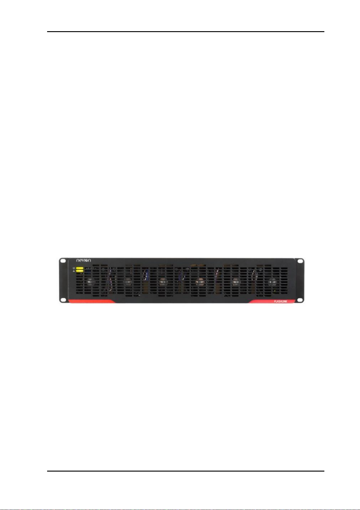
2.2 Front view
The front view of the frame shows status LEDs for the power supply modules.
Figure 1:Front view of the Flashlink frame.
The two LEDs at the front have the following functions:
Upper LED: Voltage and current alarm, internal voltages
Lower LED: Fan and temperature alarm
nevion.com | 6
Page 7
FR-2RU-20-2 Rev. A
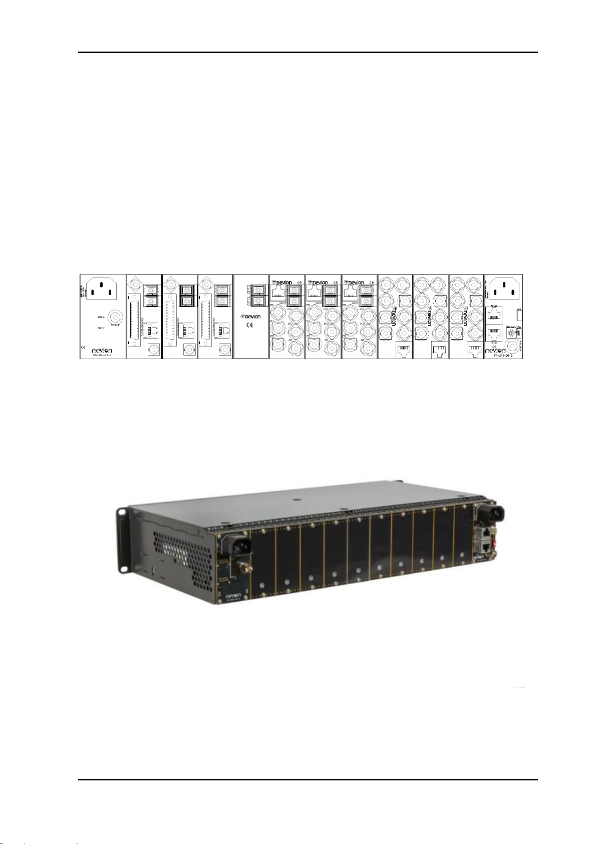
2.3 Rear view
Figure 2 shows an example of a fully equipped Flashlink frame, seen from the rear side.
The outer left and outer right modules are backplanes for the power supplies and contain
connections as follows;
- Left backplane;
o IEC-C14 AC mains inlet
o BNC, sync in
- Right backplane;
o IEC-C14 AC mains inlet
o BNC, sync out
o 2pcs. RJ-45 for RS-422 in/out
o Rotary switch for programming frame number to be read by Multicon
o 4 pin connector, GPI out
*The other connector modules are described in their respective user manuals.
Figure 2: Illustration of fully equipped Flashlink frame.
Figure 3: Flashlink frame equipped with blanks.
nevion.com | 7
Page 8

FR-2RU-20-2 Rev. A
Remark:
The power supplies support load sharing giving them extended life time. Though the total
potential power supply capacity is actually doubled in a redundant coupling, the above listed
maximum power limits for the frame shall never be exceeded.
2.4 Power consumption
The current draw in the Flashlink frame is limited by the power supplies. Overloading the
power supplies will cause them to malfunction.
The power and current limits for the frame, even with two active power supplies, are as
follows:
Total: 130W (Remaining available 30W up to 160W is dedicated for Fanboard and
fans)
+5V: 20A
+15V: 8.7A
-15V: 2A
The power consumption can be drawn from the three voltages in any combination, though
not exceeding 130W in total.
The sum of power for all cards on each rail must not be higher than the above listed limits.
The power consumption for each of the power supply rails is found in the user manual for
each Flashlink card, as this is not the same for all Flashlink cards.
nevion.com | 8
Page 9
FR-2RU-20-2 Rev. A
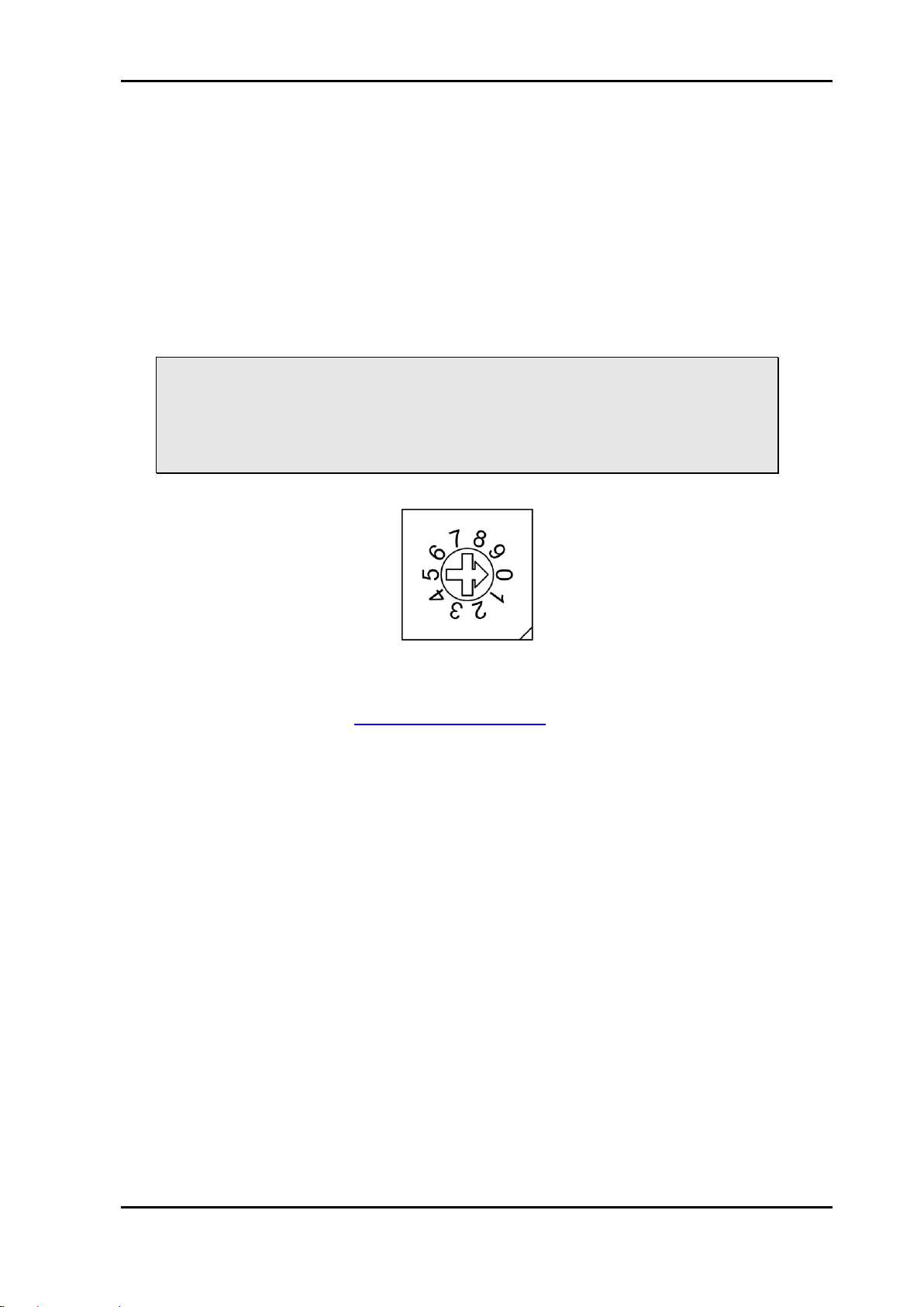
Valid positions: 0-7
3 Configuration
3.1 Address setting on each frame
Each frame can be assigned an address through the rotary switches on the rear. Maximum
8 frame addresses (0-7) are available, this means that pos. “8” and “9” on the rotary switch
are not valid
This address setting only applies when the frame is used in combination with a GYDA-SC
Rack System Controller.
If you have more than 8 frames together, you need several GYDA-SC Rack System
Controller cards.
In order to ensure proper operation of the system, it is important that no frames
controlled by the same GYDA-SC Rack System Controller card have the same
address set.
Reset the frame after reconfiguring the frame system, by turning the power off
and on again.
Figure 4: Rotary switch
More detailed information on the RS-422 configuration can be found in a separate
document and at our web site: http://www.nevion.com/
nevion.com | 9
Page 10
FR-2RU-20-2 Rev. A
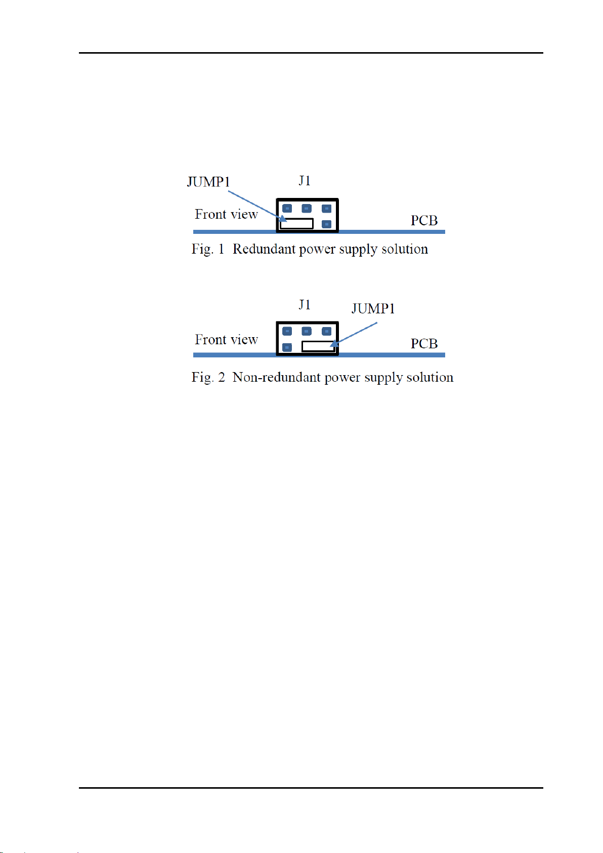
3.2 PSU redundancy mode selection
The frame comes equipped with a jumper mounted at the programming header at the
Fanboard.
Depending on the desired mode the jumper shall be mounted as described in the figure
below.
Figure 5: Location of jumper for redundancy mode selection
nevion.com | 10
Page 11

FR-2RU-20-2 Rev. A
GND
Not connected
GPI from nearest power supply
GPI from farthest power supply
4 Connections
4.1 Power connection
Figure 3 shows the power connections of the frame as well as the RS-422 connections and
the rotary-switch for address setting of the frame.
Figure 6: Connector module for the power supply.
AC: Connect mains to the frame with a mains cord with an IEC 320 connector.
To ensure a safe connection a cable with IEC-lock connector should be used.
Such cables can be ordered from Nevion.
A green LED will light on the front when the power supply is in operation mode.
For a faulty power supply LED will have red light or no light.
4.2 GPI Power Supply Status outputs
The GPI module status outputs can be used for wiring up alarms for third party control
systems.
Figure 7: GPI connector
In an alarm situation the GPI output is connected low ohmic to GND.
nevion.com | 11
Page 12

FR-2RU-20-2 Rev. A
Pin #1
Rx A (+)
Pin #2
Rx B (-)
Pin #3
Tx A (+)
Pin #4
Reserved
Pin #5
Reserved
Pin #6
Tx B (-)
Pin #7
Not Connected
Pin #8
Not Connected
4.3 RS-422 connection
At the rear end of the frame is an RS-422 bus. When used in combination with the Multicon
Rack System Controller, up to 8 frames can be controlled. On the rear end of the frame is a
rotary switch by witch each frame can be assigned its own address (see figure 3).
The RS-422 interface is shown in figure 8.
4.3.1 Pin-out RS-422 (RJ45)
Figure 8: RS-422 pin-out.
nevion.com | 12
Page 13

FR-2RU-20-2 Rev. A
1 2 3 6
4.3.2 Connecting several frames together
Several frames can be connected to each other through the RS-422 ports on the rear of
each frame.
One GYDA-SC controller can control maximum 8 frames.
You start with the frame containing the GYDA-SC Rack System Controller, and use 1 RS422 port to loop through to the next.
The last frame connected must be terminated with 110 in order to ensure proper
operation. The other port of the rack containing the GYDA-SC controller must be left open,
and cannot be connected to other frames.
Figure 5 shows an example of how to connect 8 frames together as seen from the rear end.
By using the RS-422 interface at the GYDA-SC controller card, we control 8 frames via one
RS-422 bus.
Figure 9: Control of 8 frames with GYDA-SC.
The 110 termination plug used is a standard RJ45 plug with the following internal wiring:
Figure 10: RS-422 termination.
In the figure above, Pin 1 is connected to Pin 2 with a 110 resistor, and Pin 3 is connected
to Pin 6 with a 110 resistor.
nevion.com | 13
Page 14

FR-2RU-20-2 Rev. A
4.4 Sync input/output.
An analog sync signal may be applied to the frame via the “Sync in” BNC connector .Which
Flashlink modules that can utilize the sync signal, is described in user manual for the actual
modules.
While sync is applied, the sync termination switch must be switched to “on” (upper)
position).
nevion.com | 14
Page 15

FR-2RU-20-2 Rev. A
5 Frame operation
In order to reconfigure or expand the number of modules within a frame, the front panel
must be removed. Each module has a corresponding connector module at the rear, and is
hot swappable.
Use safety goggles when hot-swapping module cards.
If a receiver card is removed from the frame, an invisible laser beam may be
emitted inside the frame from the laser at the other end. The laser beam might
be harmful to your eyes.
5.1 Removing the front panel
Pull here Pull here
"Left circle" "Right circle"
Figure 11: Removing the front panel.
nevion.com | 15
Page 16

FR-2RU-20-2 Rev. A
Figure 12: Removing the front panel (continued).
5.2 Backplane insertion
Before installing a new Flashlink main module, the accompanying back plane must be
mounted.
Switch off the power-supply. The LED on the power module is then off. With a redundant
solution, make sure that both power supplies are switched off.
Remove all screws holding the back plane to be replaced. Remove the backplane by lifting
it straight out from the rear of the frame.
The backplanes with an optical interface have a rubber plug inside each fiber adapter to
protect from dust. This rubber plug must be removed before the backplane is inserted.
.
Figure 13: Removing the rubber plug from module cards.
nevion.com | 16
Page 17

FR-2RU-20-2 Rev. A
When mounting a backplane, the backplane connector shall always be aligned at the left
and upper corner pin, see figure 13 below.
Alignment pin
+
Figure 14: Alignment pin
If the backplane to be mounted has an EMC gasket of newest type (see fig. 14),
the procedure described below does not apply.
Figure 15: Newest EMC gasket solution
Remove the screws on the back plane to the left of where the new back plane is to be
installed (seen from the back of the frame). Lift the right hand side of it slightly.
Insert the new back plane. Carefully place the right hand-side of the back plane into the slot
first (this is the side without the EMC shielding.) Then, use your business card (or another
suitable card), and insert the left edge of the back plane as shown in Figure 15 below. This
will help avoid damage to the EMC shield when inserting the new back plane.
Figure 16: Inserting a new back plane.
After the backplanes are mounted, the main module can be inserted as described in
section 5.3
nevion.com | 17
Page 18

FR-2RU-20-2 Rev. A
5.3 Main module insertion
After the fan front is removed, full access to the card modules inside the frame is given.
Switch off the power with the power switch at the power-supply modules. The green light -at the power module is now switched off. If the power supply is redundant, make sure that
both power supplies are off.
The frames are equipped with plastic guide rails to align the module cards into their
respective positions 1 to 20. Just before a card is inserted, one should remove the plastic
cap from the fiber ferrule as shown in figure 11. Do not touch the ferrule tip with your fingers
(see chapter Error! Reference source not found. - fig. 21).
Remove plastic cap before inserting module cards
a) b)
Figure 17: Removal of plastic cap
Figure 18: Open frame.
nevion.com | 18
Page 19

FR-2RU-20-2 Rev. A
Figure 19: Overview of card positions inside a frame
Be careful when inserting the card into the frame.
The ferrule of the fiber may be damaged if it touches the frame walls. Do not
touch the ferrule tip with your fingers.
Figure 20: Marking of main module locations.
Figure 21: Inserting module cards.
nevion.com | 19
Page 20

FR-2RU-20-2 Rev. A
Card locking clip
Figure 22: Inserting module cards (continued)
Slide the card into the plastic guide rails inside the frame by pushing at the card edge until
the rear edge of the card is locked by the card lock at the end of the card rail. Then push
the card handle into vertical position. See sketches below for detailed description.
Make sure that the connector on the module card fits with the connector on the back plane
card when inserting a new module card for the first time.
nevion.com | 20
Figure 23: Inserting module cards (continued)
It should not be necessary to use any force when entering the module card into
the accompanying back plane connector.
Page 21

FR-2RU-20-2 Rev. A
5.4 Card removal
To remove a module from the frame, push the spring loaded card lock downwards and
below the lower edge of the card. Then, simultaneously with the other hand, move the card
handle from vertical to nearly horizontal position and pull the card entirely out of the rack.
When removing a receiver card from the frame (hot swapping), the laser beam
may be present inside the frame (transmitted through the fiber). To avoid
damaging your eyes, never look directly into the frame unless you are 100% sure
that no laser beam is present inside the frame.
Figure 24: Card removal
nevion.com | 21
Page 22

FR-2RU-20-2 Rev. A
5.5 PSU insertion
Figure 25: PSU insertion.
The outer left and outer right positions are allocated for PSUs.
With exception for the lacking card handle the procedure for mounting is similar to main
module insertion procedure.
In a non-redundant configuration any PSU position may be used.
5.6 PSU removal
Figure 26: PSU removal
To remove a PSU from the frame, push the spring loaded card lock downwards. Be aware
of the PSU connector release force.
Then, simultaneously with the other hand, move the metal handle from vertical to nearly
horizontal position and pull the PSU entirely out of the rack.
nevion.com | 22
Page 23

FR-2RU-20-2 Rev. A
5.7 Attaching the front panel
To attach the front panel, we invert the process described in section 5.1. Start by switching
on the power supplies.
Then move the front to upright position and push it carefully into the frame until it stops.
When correctly mounted, both LEDs at the fan front will go through a short start-up
sequence before they both provide stable light.
Figure 27: Attaching the front panel.
nevion.com | 23
Page 24

FR-2RU-20-2 Rev. A
Symbol
Green LED
Yellow LED
Red LED
No LED
PSU module
none
Power is OK
Voltage or
current alarm
Power
off
Frame front
Power is OK
Communication
problem with
fan front*
Voltage or
current alarm
Power
off**
Temperature
/fans are OK
Communication
problem with
fan front*
Temperature
/fans alarm
Power
off**
5.8 Frame status (LEDs)
PSU status is presented in the following ways:
* Lack of communication with PSU in non-RP mode or one of the PSU’s in RP mode.
(In both situations the fans will have permanent maximum speed)
** PSU in non-RP mode or both of the PSU’s in RP mode
5.8.1 Multicon
- Multicon GUI which presents the following information
o Measured voltages
o Measured currents at each frame voltage
o Total provided power
o Internal PSU temperature
o Alarm status for;
voltages
currents
total provided power
temperature
Defect fan
Figure 28: Example of PSU interface in Multicon
- GPI
o See description in chapter “GPI Power Supply Status outputs”.
nevion.com | 24
Page 25

FR-2RU-20-2 Rev. A
5.9 Fans
5.9.1 Fan operation
The fans at the front provide sufficient cooling for modules and power supplies in every
allowed load situation. Their speed is controlled by control circuits in the power supplies
based on their internal temperature. The fan speed is individually and continuously
checked, and if a fan has a speed outside expected limits, it will be reported to Multicon as
being defective and the lower LED at the fan front will change to red.
Having one defective fan in the frame shall not be considered as an emergency situation
since the total needed air flow will be maintained by an increase in speed for the remaining
fans.
Removing the fan front in a live frame may cause malfunction or damage to modules due to
excessive heat and should, as a rule, never be done.
To maintain optimal cooling, all air flow openings in the chassis must be kept uncovered.
5.9.2 Replacing defective fans
Changing a defective fan should be performed at a non-live frame.
Procedure; Please contact Nevion’s customer support department.
nevion.com | 25
Page 26

FR-2RU-20-2 Rev. A
6 Fiber optics
6.1 Laser safety precautions
Guidelines to limit hazards from laser exposure.
All the available EO units in the Flashlink range include a laser.
Therefore this note on laser safety should be read thoroughly.
The lasers emit light at 1270 nm or 1610 nm. This means that the human eye cannot see
the beam, and the blink reflex cannot protect the eye. (The human eye can see light
between 400 nm to 700 nm).
A laser beam can be harmful to the human eye (depending on laser power and exposure
time), therefore:
Be careful when connecting / disconnecting fiber pigtails (ends).
Never look directly into the pigtail of the laser/fiber.
Never use microscopes, magnifying glasses or eye loupes to look into a fiber end.
Use laser safety goggles blocking light between 1270 nm and at 1610 nm.
Instruments exist to verify light output power: Power meters, IR-cards etc.
Dette er vel ikke helt oppdatert:
Flashlink features:
The FR202(-RP) is classified as Class 1 laser product according to EN 60 8251:94/A11:96, and CFR Ch1(1997) Part 1040.10.
If the front panel is removed, the FR202(-RP) is classified as Class 1 laser product
according to EN 60 825-1:94/A11:96, and class IIIb according to
CFR Ch1(1997) Part 1040.10.
Sjekk angående denne spec:
Maximum output power: 5 mW.(Egentlig 10mW?)
Operating wavelengths: 1270 to 1610 nm
Figure 29: Laser class label
nevion.com | 26
Page 27

FR-2RU-20-2 Rev. A
6.2 Handling of optical fibers
When handling fiber optical cables and interconnections, these precautions must be taken
to ensure reliable operation:
- Do not bend the fiber too much, all fiber optical cables have a minimum bend
radius. Follow manufactures datasheet recommendation for each cable or use
40 mm as a general guideline.
- Do not apply excessive mechanical stress on the fiber optical cables or
connectors.
- Keep the connectors clean from dust. Good practice is to clean the ferrule each
time a new connection is made between two optical connectors. Always use
special fiber optical ferrule cleaner made for this purpose.
- Never touch the ferrule or make the tip of the ferrule come in contact with other
objects. Always protect ferrules on optical connectors with protective cap when
not in use.
If the above precautions are not taken, the optical signal may be degraded or even lost
completely and the equipment will not function properly.
6.3 Optical connectors
The Flashlink product range utilizes among others SC/PC connectors.
An illustration of the different parts of the fiber optical connector are shown below.
Figure 30: The different parts of an SC/PC Connector.
Clean connectors are of crucial for reliable operation.
nevion.com | 27
Page 28

FR-2RU-20-2 Rev. A
Byte 0
Rack ID (0-7); Destination
Byte 1
Card position (0-19); Destination
Byte 2
Rack ID (0-7); Source
Byte 3
Card position (0-19); Source
Byte 4 – n
Command or command response
Byte n+1
Linefeed (10 decimal, 0x0A hex)
7 Flashlink control protocol
7.1 Document conventions
All commands sent to the card are printed in italics.
This is a command sent to a card.
All responses sent from a card to the controller are printed in bold.
This is a response sent from a card to the controller.
7.2 Hardware interface
The hardware interface is basically RS-422, a serial communication standard much like RS232 but with balanced lines. You can use a simple (dumb) RS-232 to RS-422 converter if
you want to use a standard RS-232 port (eg. a PC COM port).
The receive and transmit lines can be connected to make a true RS-485 bus, but this
requires special care from the PC side, since you have to control the bus direction (e.g.
using a dedicated RS-485 board with RS-485 drivers). We recommend using RS-422 for
control.
Data rate: 115200 bps, 8 bits, with one stop bit and no parity.
All data is 8 bit ASCII (ISO8859-1 encoding, but currently any ASCII encoding will do since
no special ASCII characters are used).
7.3 Addressing
Each card has a unique identifier called card position, which is assigned (trough hardware
pinning) automatically when a card is inserted into a subrack. The card positions are
numbered from 1 to 20 from a user point of view. From a protocol (or software) point of
view, the cards are numbered 0-19. When we refer to card position in this document, we
refer to this "low level id" numbered 0-19, but the user should always see positions 1-20 in
menus, etc.
Each frame (if you use more than one) should have a unique frame id, numbered 0-7 (user
and protocol/software wise). The id is set by rotary switches on the rear of the rack, behind
the power supply at the left side.
7.4 General command structure
Each command is built up of a sequence of ASCII characters terminated by linefeed. The
first two characters are the source address (source frame id and the source card position).
Frame structure:
If the command or command response contains a line feed, it is preceded by a backslash
(\).
7.5 Card detection (hot swap)
The controller must send a "hello" command to gain control over a board, this is to make
sure that the control software is aware of any card changes. After a power up or hot swap,
the card does not respond to any other command than hello.
nevion.com | 28
Page 29

FR-2RU-20-2 Rev. A
7.6 Hello command
This command establishes communication with a new unit. An example of communication
with SDI-EO and SDI-OE is shown in the following. The command is short (a single
question mark) to save bandwidth. The card will respond with card info. If the card is not
present, the command times out.
A typical response would be:
0409?
0904EO/SDI/1310nm,-7.5dBm\
hw rev 1.0\
sw rev 1.0\
protocol ver 1.0
This is an electrical to optical converter for SDI, with a -7.5dBm 1310nm laser. The
hardware revision is ver 1.0, and the software version is ver 1.0. The protocol version is 1.0.
7.7 Electrical to optical converters
7.7.1 Hello command
An EO converter will respond to a hello command with:
0409?
0904EO/SDI/1310nm,-7.5dBm\
hw rev 1.0\
sw rev 1.0\
protocol ver 1.0
or
0409?
0904EO/T140/1310nm,-7.5dBm\
hw rev 1.0\
sw rev 1.0\
protocol ver 1.0
7.7.2 Info command
The card will respond to the command string "info" by sending the card status. This is a
typical example.
0409info
0904laser on\
SDI signal strength = 81 %\
vcc = 5.04 V\
laser fail: no
nevion.com | 29
Page 30

FR-2RU-20-2 Rev. A
7.8 Optical to electrical converters
7.8.1 Hello command
An OE converter will respond to a hello command with:
0409?
0904OE/SDI/reclocking, not calibrated\
hw rev 1.0\
sw rev 1.0\
protocol ver 1.0
or
0409?
0904OE/T140/reclocking, not calibrated\
hw rev 1.0\
sw rev 1.0\
protocol ver 1.0
"Not calibrated" refers to the optical power measurement which is not calibrated.
7.8.2 Info command
The card will respond to the command string "info" by sending the card status. This is a
typical example.
0409info
0904signal = -12.2 dBm\
optical signal: yes\
reclocker locked: yes\
vcc = 4.97V
Note that since the optical signal strength is not calibrated, the measurement will be wrong
(typ. +/- 5 dB).
nevion.com | 30
Page 31

FR-2RU-20-2 Rev. A
1.
The equipment will meet the guaranteed performance specification under the
following environmental conditions:
-
Operating room temperature range:
0°C to 45°C
-
Operating relative humidity range:
< 90% (non-condensing)
2.
The equipment will operate without damage under the following environmental
conditions:
-
Temperature range:
-10°C to 55°C
-
Relative humidity range:
< 95% (non-condensing)
General environmental requirements for Flashlink equipment
nevion.com | 31
Page 32

FR-2RU-20-2 Rev. A
Product Warranty
The warranty terms and conditions for the product(s) covered by this manual follow the
General Sales Conditions by Nevion, which are available on the company web site:
www.nevion.com
nevion.com | 32
Page 33

FR-2RU-20-2 Rev. A
組成名稱
Part Name
Toxic or hazardous substances and elements
鉛
Lead
(Pb)
汞
Mercury
(Hg)
镉
Cadmium
(Cd)
六价铬
Hexavalent
Chromium
(Cr(VI))
多溴联苯
Polybrominated
biphenyls
(PBB)
多溴二苯醚
Polybrominated
diphenyl ethers
(PBDE)
<Product>
O O O O O
O
<Power supply, if
delivered with unit>
O O O O O
O
O: Indicates that this toxic or hazardous substance contained in all of the homogeneous materials for this part is
below the limit requirement in SJ/T11363-2006.
X: Indicates that this toxic or hazardous substance contained in at least one of the homogeneous materials used
for this part is above the limit requirement in SJ/T11363-2006.
Appendix A Materials declaration and recycling
information
A.1 Materials declaration
For product sold into China after 1st March 2007, we comply with the “Administrative Measure
on the Control of Pollution by Electronic Information Products”. In the first stage of this
legislation, content of six hazardous materials has to be declared. The table below shows
the required information.
This is indicated by the product marking:
A.2 Recycling information
Nevion provides assistance to customers and recyclers through our web site
http://www.nevion.com/. Please contact Nevion’s Customer Support for assistance with
recycling if this site does not show the information you require.
Where it is not possible to return the product to Nevion or its agents for recycling, the following
general information may be of assistance:
Before attempting disassembly, ensure the product is completely disconnected from
power and signal connections.
All major parts are marked or labeled to show their material content.
Depending on the date of manufacture, this product may contain lead in solder.
Some circuit boards may contain battery-backed memory devices.
nevion.com | 33
 Loading...