

Nevion eMerge EM-GE-48T, eMerge EM-GE-24T, eMerge EM-GE-48S, eMerge EM-GE-24S, eMerge EM-GE-4SFP+ User Manual
...Page 1

Nevion
Nordre Kullerød 1
3241 Sandefjord
Norway
Tel: +47 33 48 99 99
nevion.com
eMerge EM-GE Ethernet Media Router
User Manual
User manual
Rev. A
Page 2

eMerge EM-GE Ethernet Media Router Rev. A
nevion.com | 2
Nevion Support
Nevion Europe
P.O. Box 1020
3204 Sandefjord, Norway
Support phone 1: +47 33 48 99 97
Support phone 2: +47 90 60 99 99
Nevion USA
1600 Emerson Avenue
Oxnard, CA 93033, USA
Toll free North America: (866) 515-0811
Outside North America: +1 (805) 247-8560
E-mail: support@nevion.com
See http://www.nevion.com/support/ for service hours for customer support globally.
Revision history
Current revision of this document is the uppermost in the table below.
Rev.
Repl.
Date
Sign
Change description
A - 04.12.2014
MW
Initial revision
Page 3

eMerge EM-GE Ethernet Media Router Rev. A
nevion.com | 3
Contents
Revision history ........................................................................................................ 2
1 Product overview ................................................................................................... 4
1.1 Product Model ............................................................................................................... 4
1.2 Front Panel (eMerge EM-GE-24/48) .............................................................................. 5
1.3 Front Panel (eMERGE EM-GE-24/48S) ........................................................................ 6
1.4 Rear Panel (eMERGE EM-GE-24T/48T/24S/48S) ........................................................ 6
1.5 eMERGE EM-GE Network Uplink Module Introduction .................................................. 7
1.6 eMERGE EM-GE Series LED Introduction .................................................................... 7
2 Installation ........................................................................................................... 11
2.1 Preparation for Installation ...........................................................................................11
2.1.1 Safety Precaution ......................................................................................................11
2.1.2 Installation Site ..........................................................................................................11
2.1.3 Installation Tools .......................................................................................................13
2.2 Installation ....................................................................................................................14
2.2.1 Introduction of Front and Rear Mounting Brackets ....................................................14
2.2.2 Install the switch with Front Mounting Brackets and a Rack Tray ..............................15
2.2.3 Install the switch with Front and Rear Mounting Brackets ..........................................16
2.2.4 Install the Router on a Workbench ............................................................................18
2.2.5 Installing Uplink Network Module ...............................................................................18
2.2.6 Installation and Removal of Power Module ................................................................19
2.2.7 Installation of Fan Module .........................................................................................20
2.3 Grounding Connection .................................................................................................20
2.3.1 Grounding Connection ..............................................................................................20
2.4 Power Wire Connection ................................................................................................21
2.4.1 AC Power Wire Connection .......................................................................................21
2.4.2 DC Power Wire Connection .......................................................................................22
3 Interface Module and Cable Connection Description ........................................... 24
3.1 Interface Module Description ........................................................................................24
3.1.1 10/100/1000 Ports .....................................................................................................24
3.1.2 Ethernet Port .............................................................................................................25
3.1.3 Console Port .............................................................................................................26
4 Initial Power-on & Start-up of Router ................................................................... 27
4.1 Building Configuration Platform and Connecting Cable ................................................27
4.2 Setting Terminal Parameter ..........................................................................................27
4.3 Router Power-On .........................................................................................................30
5 Router Software Loading ..................................................................................... 31
6 Upgrade of Operating System ............................................................................. 32
7 Maintenance and Troubleshooting ...................................................................... 33
7.1 Loading Failure Processing ..........................................................................................33
7.2 User Password Lost .....................................................................................................33
7.3 Power System Troubleshooting ....................................................................................33
7.4 Configuration System Troubleshooting .........................................................................33
General environmental requirements for Nevion equipment .................................. 35
Product Warranty.................................................................................................... 36
Appendix A Materials declaration and recycling information .................................. 37
A.1 Materials declaration ................................................................ ....................................37
A.2 Recycling information ...................................................................................................37
Page 4
eMerge EM-GE Ethernet Media Router Rev. A
nevion.com | 4
1 Product overview
eMERGE EM-GE series are a new generation Ethernet Media Router developed by Nevion,
designed to meet the requirements for high performance and high reliability. eMERGE EMGE series of Ethernet Media Router are mainly targeted at customers’ needs for enterprise
or carrier network aggregation or access layer. Hardware support for IPv4 & IPv6 dual stack
and enhanced multicast and QoS capabilities can provide customers with a wealth of
business features and routing functions, as well as hardware-based security features.
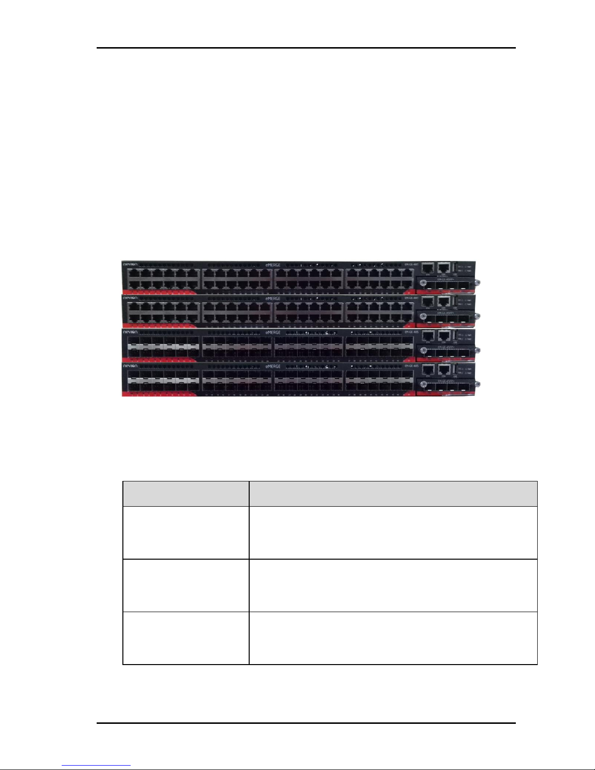
The eMERGE EM-GE Series provides high port density with 48GE fixed port and adopts
flexible modular design to support maximum 4 x 10G uplinks.
The eMERGE EM-GE Series (Figure 1-1) includes four base configurations: eMERGE EMGE-48T/ eMERGE EM-GE-24T/ eMERGE EM-GE-48S/ eMERGE EM-GE-24S, and provide
three uplink modules: EM-GE-4SFP+/EM-GE-2SFP+/EM-GE-4SFP (Only for eMERGE EMGE-48T & eMERGE EM-GE-24T).
Figure 1: eMerge EM-GE Series Ethernet Media Router
1.1 Product Model
Table 1: eMerge EM-GE Series of Ethernet Media Router Models
Model
Description
EM-GE-48T
Standard 1U 19’’ rack mountable
48x10/100/1000 Base-T Ethernet Port
Modular Uplink
EM-GE-24T
Standard 1U 19’’ rack mountable
24x10/100/1000Base-T Ethernet Port
Modular Uplink
EM-GE-48S
Standard 1U 19’’ rack mountable
48x100/1000 Base-X SFP Ethernet Port
Modular Uplink
Page 5

eMerge EM-GE Ethernet Media Router Rev. A
nevion.com | 5
Model
Description
EM-GE-24S
Standard 1U 19’’ rack mountable
24x100/1000 Base-X SFP Ethernet Port
Modular Uplink
EM-GE-4SFP+
Uplink Module for eMERGE EM-GE Series
4 x 10G SFP+ Ethernet Port (eMERGE EM-GE48T&eMERGE EM-GE-24T support 1GE SFP optical module,
Combo with last RJ45 ports)
EM-GE-2SFP+
Uplink Module for eMERGE EM-GE Series
2 x 10G SFP+ Ethernet Port (EM-GE-48T& EM-GE-24T
support 1GE SFP optical module, Combo with last RJ45 ports)
EM-GE-4SFP
Uplink Module for eMERGE EM-GE Series
4x1000Base-X SFP Ethernet Port (Only for eMERGE EMGE-48T&eMERGE EM-GE-24T)
1.2 Front Panel (eMerge EM-GE-24/48)
Figure 2: Front Panel Sketch Map of eMERGE EM-GE-24/48T
1: 10/100/1000Base-T Ethernet Ports
2: 10/100/1000Base-T Ethernet Ports Status LED
3: SFP or SFP+ Network Uplink Card
4: SFP or SFP+ Network Uplink Ports Status LED
5: SFP or SFP+ Network Uplink Ports
6: Airflow Input Holes
7: Management Ethernet Interface
8: RJ45 Console Port
9: USB Interface (Extend Flash Memory)
10: System Status LED (SYS)
11: Fan LED (FAN)
12: Power Supply 1 LED (PWR1)
13: Power Supply 2 LED (PWR2)
Page 6

eMerge EM-GE Ethernet Media Router Rev. A
nevion.com | 6
1.3 Front Panel (eMERGE EM-GE-24/48S)
Figure 3: Front Panel Sketch Map of eMERGE EM-GE-24/48S
1: 100/1000Base-X SFP Ethernet Ports
2: 100/1000Base-X SFP Ethernet Ports Status LED
3: SFP+ Network Uplink Card
4: SFP+ Network Uplink Ports Status LED
5: SFP+ Network Uplink Ports
6: Airflow Input Holes
7: Management Ethernet Interface
8: RJ45 Console Port
9: USB Interface (Extend Flash Memory)
10: System Status LED (SYS)
11: Fan LED (FAN)
12: Power Supply 1 LED (PWR1)
13: Power Supply 2 LED (PWR2)
1.4 Rear Panel (eMERGE EM-GE-24T/48T/24S/48S)
Figure 4: Rear Panel Sketch Map of eMERGE EM-GE-24T/48T/24S/48S
1: Grounding Screw
2: Fan Module
3: Fan Module Handle
4: AC or DC Power Supply Module (Power Supply Slot 1)
5: Fan of Power Supply Module (FRU)
6: Power Supply Module Handle
7: Power Supply Lock
8: Blank Panel (Power Supply Slot 2)
Page 7

eMerge EM-GE Ethernet Media Router Rev. A
nevion.com | 7
1.5 eMERGE EM-GE Network Uplink Module Introduction
Picture
Network
Uplink Module
Description
EM-GE-4SFP+
4 x 10G SFP+ Ethernet Port
EM-GE-2SFP+
2 x 10G SFP+ Ethernet Port
EM-GE-4SFP
4 x 1000Base-X SFP
Ethernet Port (Only for EM-
GE-48T& EM-GE-24T,
Combo with last RJ45 ports)
eMERGE EM-GE uplink network module does not support hot swappable. If you
need to install or remove the network module, please turn off power of the switch,
and then complete the related operation.
1.6 eMERGE EM-GE Series LED Introduction
System LED Indicator
Indicator
Status
Description
SYS
Green
On
System is abnormality.
Blinking Quickly (2Hz)
The system is power on but CPU is not
running.
Blinking Slowly
(0.5Hz)
The system is normal running.
Amber
Blinking Quickly (2Hz)
The system is in u-boot initiation
Blinking Slowly
(0.5Hz)
The system is in system initiation
On
The system occur alarm or error.
-
Off
No power or System is not run or
abnormality
Page 8

eMerge EM-GE Ethernet Media Router Rev. A
nevion.com | 8
FAN LED Indicator
Indicator
Status
Description
FAN
Green
On
The Fans/fan tray are ok
Amber
On
Fans are bad.
-
Off
No power or fan tray is absent.
Power Supply LED Indicator
Indicator
Status
Description
PWR1
Green
On
Power supply ok
Amber
On
Power supply is abnormality
-
Off
Power supply is absent or single
power supply abnormality.
PWR2
Green
On
Power supply ok
Amber
On
Power supply is abnormality
-
Off
Power supply is absent or single
power supply abnormality.
Ethernet Management Interface LED Indicator
Indicator
Status
Description
ETH
Green(Left)
On
10/100M port link.
Off
Port not link
Green(Right)
On
Port link.
Blinking
10/100M packets receiving or
transmitting.
Off
Port not link
Page 9

eMerge EM-GE Ethernet Media Router Rev. A
nevion.com | 9
10/100/1000 Base-T Indicator(eMERGE EM-GE-24/48T)
Indicator
Status
Description
1-24 / 1-48
Green
On
1000M port link.
Blinking
1000M packets receiving or
transmitting.
Off
Port not link
Amber
On
10/100M port link.
Blinking
10/100M packets receiving or
transmitting.
Off
Port not link
100/1000 Base-X SFP Indicator (eMERGE EM-GE-24/48S)
Indicator
Status
Description
1-24 / 1-48
Green
On
1000M port link.
Blinking
1000M packets receiving or
transmitting.
Off
Port not link
Amber
On
100M port link.
Blinking
100M packets receiving or
transmitting.
Off
Port not link
1001000 Base-X Indicator (EM-GE-4SFP for eMERGE EM-GE-24/48T)
Indicator
Status
Description
1-4
Green
On
1000M port link.
Blinking
1000M packets receiving or
transmitting.
Off
Port not link
Amber
On
100M port link.
Blinking
100M packets receiving or
transmitting.
Off
Port not link
Page 10

eMerge EM-GE Ethernet Media Router Rev. A
nevion.com | 10
10G Base-X SFP+ Indicator (EM-GE-2SFP+ /EM-GE-4SFP+)
Indicator
Status
Description
1-2 / 1-4
Green
On
10G port link.
Blinking
10G packets receiving or transmitting.
Off
Port not link
Page 11

eMerge EM-GE Ethernet Media Router Rev. A
nevion.com | 11
2 Installation
2.1 Preparation for Installation
2.1.1 Safety Precaution
The following precautions should be followed to avoid equipment damage and personal injury
caused by improper use:
-
Power source should be removed before cleaning switches. Do not use wet rags to
wipe switches and clean switches with liquid.
-
Do not place switches near water or in a wet environment, and prevent water or
moisture from entering switch chassis.
-
Do not place switches on an unstable case or table, since the dropping would cause
serious harm to switches.
-
Maintain good indoor ventilation and clear air holes of switches.
-
Router shall work normally under correct voltage, so make sure the operating voltage
agrees with the voltage marked on switches.
-
To reduce the risk of electric shock, do not remove its enclosure when a switch is
working, and don’t do so at will even if it is not powered.
-
Anti-static gloves must be worn when replacing interface board to prevent static
electricity from damaging veneer.
2.1.2 Installation Site
To ensure a normal work environment, eMERGE EM-GE series should have the following
requirements for workplace:
-
Ensure that there are some spaces at the inlet and outlet of switch for heat dispersion
of switch chassis.
-
Ensure that rack and working platform have good ventilation and heat dispersion
systems.
-
Ensure that rack and working platform is firm enough to support the weight of a
switch and its accessories for installation.
-
Ensure rack and working platform is well earthed.
To ensure switches maintain a long-term stable work, the installation workplace should also
meet the following requirements:
Temperature/Humidity Requirements
To ensure the normal work and service life of switches, certain temperature and humidity
should be maintained inside switch rooms. Longtime higher humidity inside switch rooms
may easily lead to poor insulation or even electric leakage of dielectrics, and sometimes
cause material changes in mechanical features and corrosion of metal parts; if the relative
humidity is lower, insulation pads could dry shrink to make fastening screws loose.
Meanwhile, in the dry climate, lower relative humidity could easily cause static electricity
which will impose harms to the circuit of switch; higher temperature would be even more
harmful: longtime high temperature would accelerate aging process of insulation materials to
greatly reduce the reliability of switches and severely affect their service life.
Page 12

eMerge EM-GE Ethernet Media Router Rev. A
nevion.com | 12
Table 2: Temperature/Humidity Requirements
Item
eMERGE EM-GE Series
Temperature
0~45℃
Humidity
10%~95%
Cleanliness Requirements
Dust is a big hazard to the safe operation of switches. Indoor dust falling on the switch body
can cause electrostatic adsorption to make poor contact of metal connectors or metal
contacts. Especially when the indoor relative humidity is lower, electrostatic adsorption is
easily formed, which will not only affect equipment service life, but also easily lead to
communication failure.
Table 3: Dust Content Requirements in Router Room
Substance
Unit
Concentration limit
DUST
Particle/m3
≤ 3 X 10⁴ (No visible dust on the tabletop for three days)
Note: The dust particle size is ≥ 5 μm
Besides dust, there are rigorous limits on the content of harmful substances that can
accelerate the corrosion and aging of metals, such as salts, acids, and sulfides in the air in
the equipment room, and the equipment room must be protected against ingression of
harmful gases such as SO2, H2S, NH3, and Cl2. For the specific requirement, see the following
table.
Table 4: Harmful Gas Threshold in the Equipment Room
Gas
Maximum concentration (mg/m3)
SO2
0.2
H2S
0.006
NH3
0.05
Cl2
0.01
Electromagnetic Susceptibility
Router may be affected by the interferences from outside the system, which will have an
effect on devices through conduction of capacitance coupling, inductive coupling,
electromagnetic wave radiation, common impedance (including ground system) coupling and
wires (power wire, signal wire and output signal wire, etc.). The following attention should be
paid to:
-
AC power supply system is TN system, and AC power socket should be single-phase
3-wire outlet with protective earth (PE) so that filter circuit on devices can effectively
filter interference from electric grid.
-
Places where switches work should be kept away from strong-power radio
transmitting station, radar transmitting station, high-frequency high-current devices.
Page 13

eMerge EM-GE Ethernet Media Router Rev. A
nevion.com | 13
-
Electromagnetic shielding should be adopted when necessary, i.e. interface cables
use shielded cables.
-
Interface cables are required to be arranged indoors instead of outdoors to prevent
signal ports of devices from being damaged by over voltage and over current
generated from lightning.
Laser Use Safety
-
eMERGE EM-GE series are Class 1 laser devices.
-
Do not stare at the optical interfaces directly when the optional optical interfaces of
eMERGE EM-GE series are in operating mode, since light beam emitting from fiber
has high energy which may be harmful to retina.
2.1.3 Installation Tools
Prepare the following tools before installation:
-
Flathead screwdrivers
-
Phillips screwdrivers
-
ESD-preventive wrist strap
The installation tools are not provided with eMERGE EM-GE Series Routing Router.
Page 14

eMerge EM-GE Ethernet Media Router Rev. A
nevion.com | 14
2.2 Installation
eMERGE EM-GE series of switches can be installed in a 19” standard rack in the following
3 ways:
-
Install the switch with Front Mounting Brackets and a Rack Tray
-
Install the switch with Front and Rear Mounting Brackets
-
Install the Router on a Workbench
2.2.1 Introduction of
Front and Rear
Mounting Brackets
Front Mounting Brackets
Figure 5: Appearances Sketch Map of Front Mounting Brackets
Description:
(1): Screw hole for fixing Front Mounting Brackets and rack
(2): Screw hole for fixing Front Mounting Brackets and switch
Front Mounting Brackets are only used to fix switches, but unable to bear the weight.
Page 15

eMerge EM-GE Ethernet Media Router Rev. A
nevion.com | 15
Rear Mounting Brackets
The Rear Mounting Brackets are optional components, and can be used together with Rear
Mounting Brackets to bear the weight of the switch.
Figure 6: Appearance Sketch Map of Rear Mounting Brackets
Description:
(1): Screw hole for fixing Rear Mounting Brackets and rack
(2): Screw guide groove for fixing Rear Mounting Brackets and switch
2.2.2 Install the switch with Front Mounting Brackets and a Rack Tray
Installation Process
Step 1: Wear ESD-preventive wrist strap, and check the grounding and stability of
rack.
Step 2: Fix the tray to a proper position of rack horizontally.
Step 3: Take out screw (complete package with front hangers), and install one end
of the Front Mounting Brackets on switch, as shown in Figure 7.
Figure 7: Installation Sketch Map of Front Mounting Brackets
Page 16

eMerge EM-GE Ethernet Media Router Rev. A
nevion.com | 16
Step 4: Place switch on the tray horizontally, push it slightly into the rack along the
tray, and fix the other end of Front Mounting Brackets upon the front hold strip of
rack using screw and its matching floating nut.
Figure 8: Installation Sketch Map of Front Mounting Brackets with Tray
2.2.3 Install the switch with Front and Rear Mounting Brackets
Installation Process
Step 1: Wear ESD-preventive wrist strap, and check the grounding and stability of
rack.
Step 2: Install the Rear Mounting Brackets to the rear of the Rack.
Figure 9: Installation Sketch Map of Rear Mounting Brackets
Page 17

eMerge EM-GE Ethernet Media Router Rev. A
nevion.com | 17
Step 3: Take out screw (complete package with front hangers), and install one end
of the Front Mounting Brackets on switch, as shown in Figure 10.
Figure 10: Installation Sketch Map of Front Mounting Brackets
Step 4: To hold and insert the Router to the Rack horizontally. Use the screws and
its matching floating nut to fix the Front Mounting Brackets upon the front of rack.
Figure 11: Installation Sketch Map of Front Mounting Brackets (to the Rack)
Step 5: In the two sides of the back end of the switch, use the screws to fix the
switch by the screw guide groove of the Rear Mounting Brackets. (Depending on the
depth of the Router, use four or six screws.)
Figure 12: Installation Sketch Map of the Rear Mounting Brackets
Page 18

eMerge EM-GE Ethernet Media Router Rev. A
nevion.com | 18
2.2.4 Install the Router on a Workbench
In many cases, users do not have a standard 19” rack, so people often place switches on a
cleaning working platform. Such operation is relatively simple, and the only following aspects
should be concerned during operation:
Step 1: Ensure the working platform is stable and well earthed.
Step 2: A 10 cm space around switch is left for heat dissipation.
Step 3: Do not place heavy objects on switches.
Step 4: There are 4 foot pads that come with the device. Paste them onto the bottom
near the corners of the switch, as shown below:
Figure 13: Installation Sketch Map of the foot pads
2.2.5 Installing Uplink Network Module
eMERGE EM-GE Series support Extend Uplink Network slot. eMERGE EM-GE-24/48T
supports 3 uplink modules: EM-GE-4SFP+/ EM-GE-2SFP+/ EM-GE-4SFP. eMERGE EMGE-24/48S supports 2 uplink modules: EM-GE-4SFP+/ EM-GE-2SFP+.
Network module installation process is as follows:
Step 1: Wear the ESD wrist strap, and confirm the anti-static wrist good grounding.
Step 2: Disconnect all power connection with switch.
Step 3: Network control module is slowly inserted into the network expansion slot,
then the thumb of two hands respectively hold left and right ends of the frame of
Network Uplink Module, and push to the switch. The Uplink Network module is aligned
with the front panel switch.
Step 4: With a crosshead screwdriver, tighten the fastening screws at the left and right
of the Uplink Network Module.
eMERGE EM-GE uplink network module does not support hot swappable. If you need to
install or remove the network module, please turn off power of the switch, and then
complete the related operation.
Page 19

eMerge EM-GE Ethernet Media Router Rev. A
nevion.com | 19
2.2.6 Installation and Removal of Power Module
Installation Process
The power modules for eMERGE EM-GE series are pluggable. Installation process of power
modules is as follows:
Step 1: Wear ESD-preventive wrist strap, and confirm that the anti-static wrist strap
is well earthed.
Step 2: Maintain correct up-down direction of power module (in line with the positive
direction of characters, if turned upside down, the power module cannot be inserted
to the end due to structural limit specially designed inside chassis), grip the handle on
the front end of power module to be installed with one hand and support the bottom
of power module with another hand, and insert the power module by smoothly sliding
along the power slot until the plug of power module comes into full contact with the
socket inside chassis.
Step 3: Tighten up the fastening screws on the left and right sides of power module
with a cross-head screwdriver. The following are the complete installation sketch map
of the AC power module. The installation for DC power module is similar with AC.
Figure 14: Installation Sketch Map of AC power module
Removal Process
The power modules for eMERGE EM-GE series are pluggable. Removal process of power
modules is as follows:
Step 1: Wearing anti-static wrist strap, and confirm that the anti-static wrist strap is
well earthed.
Step 2: Disconnect all power connectors of switches.
Step 3: Undo the fastening screws on the left and right sides of power module with a
cross-head screwdriver.
Step 4: Grip the handle on the front end of power module to be installed with one hand
and press on the top switch with another hand, and pull out the power module by smoothly
sliding along the power slot until the plug of power module is completely separated from
the socket inside chassis.
The eMERGE EM-GE switch can be installed with two power supply modules as hot
backup. When one of the two power modules failure, user can replace the bad power
module on line (Without interruption for Router power supply).
Page 20

eMerge EM-GE Ethernet Media Router Rev. A
nevion.com | 20
2.2.7 Installation of Fan Module
The fan module of eMERGE EM-GE is pluggable, so it’s easy to be installed, but users should
ensure that the interval between removing the old fan module and inserting a new one is not
more than 1 minute during the replacement of fan; otherwise higher temperature in switch
will cause damage to switches.
Step 1: Undo the fastening screws on the left and right sides of power module with a
cross-head screwdriver.
Step 2: Hold the handle of fan module, and gently pull out the fan module.
Step 3: Insert a new fan module; fix it with a little force. The fan module will be firmly
inserted into the backplane of the switch and integrated with it closely.
Step 4: Tighten the fastening screws on both sides of power module with a
screwdriver to fix the power module.
The fan module of eMERGE EM-GE switch supports hot plug function, it is
convenient for maintenance and replacement online.
The fan module provides cooling function for the switch. If you need to replace a
failed fan module, it is recommended to complete the operating within three minutes
(prevent the temperature inside the switch is too high).
2.3 Grounding Connection
2.3.1 Grounding Connection
A noise filter is connected on the power input of switch, whose central earthing is connected
directly to the cabinet, which is called enclosure earthing (that is PE). This cabinet must be
well grounded to enable the safe flow of influence electricity and leakage into the earth and
increase the anti-electromagnetic interference of switch.
Correct way of grounding is as follows:
Connect one end of the yellow and green PE cable of switch to the terminal of grounding bar
and screw up the fastening nut when there is a grounding bar in the installation environment
of Ethernet switches.
Note: it is an incorrect option to be grounded with fire mains and a lightning rod in a building,
so the ground wires of Ethernet switches should be connected to the works in switch room
and grounded.
Page 21

eMerge EM-GE Ethernet Media Router Rev. A
nevion.com | 21
Figure 15: Grounding Installation Sketch when a Grounding Bar is in Router Room
Description:
(1): Power input of switch
(2): Ground terminal of switch
(3): Protective grounding cable
(4): Grounding bar of switch room
The Router's ground connection is very important for lightning and anti-interference
protection, so please user must connect the grounding wire correctly.
The grounding connection figure provided in this guide is for reference only, please
following the real installation situation to connect the grounding wire of the Router
correctly.
2.4 Power Wire Connection
2.4.1 AC Power Wire Connection
Step 1: Connect one end of the earth wire on enclosure included in a switch to the earthing
screw on back panel of the switch, and the other end is earthed handily.
Step 2: Insert one end of the power wire of the switch into the outlet on back panel of the
cabinet, and the other end into an AC power outlet.
Figure 16: Sketch Map of AC Power Wire connection
Page 22

eMerge EM-GE Ethernet Media Router Rev. A
nevion.com | 22
Step 3: Turn on the power switch, and check if the power indicator on front panel of
the switch is bright, which indicates that power connection is correct.
The earth wire must be connected before switches are powered on.
2.4.2 DC Power Wire Connection
Step 1: Connect one end of the earth wire on enclosure included in a switch to the
earthing screw on back panel of the switch, and the other end is earthed handily.
Step 2: Red cable is connected to positive pole, and Black cable is connected to
negative pole. Fasten the screws on top of the connector.
Figure 17: Install the DC Power Wire to the connector
Step 3: Insert the connector to DC PSU, and then fasten the screws on both sides.
Figure 18: Insert the DC Connector
Page 23

eMerge EM-GE Ethernet Media Router Rev. A
nevion.com | 23
Step 4: Connection style for the 48V DC power source side: Red cable is connected
to positive pole, and Black cable is connected to negative pole.
Figure 19: Connect the DC Power Wire to power source
The earth wire must be connected before switches are powered on.
Page 24

eMerge EM-GE Ethernet Media Router Rev. A
nevion.com | 24
3 Interface Module and Cable Connection Description
3.1 Interface Module Description
3.1.1 10/100/1000 Ports
10/100/1000 Base-T Ethernet interface can use RJ-45 connectors. Its maximum transmission
distance is 100m. The transmission of 100Base-TX and 1000 Base-T needs to use CAT 5 or
enhanced CAT 5 twisted pair wires, or CAT 6 non-unshielded twisted pair wires. While the
transmission of 10 Base-T can use CAT 3 or CAT 4 twisted pair wires.
By default, 10/100/1000M auto-negotiation are enabled for RJ45 connectors for eMERGE
EM-GE Series Routing Router. By this setting, when two switches are connected, the
switches can automatically negotiate work environment and parameters to be used in
automatic configuration. If one switch does not support this feature, network administrators
or related personnel need to conduct configurations manually. See Configuration Manual for
specific manual configuration methods.
Definition of RJ45 Pins as shown below:
Figure 20: Sketch Map of RJ-45 Connector Pins
Table 5: Definition of Ethernet RJ45 Port Straight Through Line:
Through Mode
Pin No.
Description
Description
Pin No.
1
TX+
RX+
1 2 TX-
RX-
2
3
RX+
TX+
3
4
N/A
N/A
4 5 N/A
N/A
5 6 RX-
TX- 6 7
N/A
N/A
7
8
N/A
N/A
8
Page 25

eMerge EM-GE Ethernet Media Router Rev. A
nevion.com | 25
Table 6: Definition of Ethernet RJ45 Port Cross-Over Line:
Cross Mode
Pin No.
Description
Description
Pin No.
1
TX+
RX+
3 2 TX-
RX-
6
3
RX+
TX+
1
4
N/A
N/A
4 5 N/A
N/A
5
6
RX-
TX-
2
7
N/A
N/A
7
8
N/A
N/A
8
You may refer to the following standard line sequence for making straight-through line and
cross-over line:
Figure 21: Ethernet Line Sequence
3.1.2 Ethernet Port
eMERGE EM-GE series are integrated with out-of-band Ethernet ports whose interfaces are
100 Base-TX or 10 Base-T. It is recommended to use the net line included.
Page 26

eMerge EM-GE Ethernet Media Router Rev. A
nevion.com | 26
3.1.3 Console Port
Console port uses an 8-pin RJ-45 connector. When connecting the console port of switch to
a computer, we need an RJ-45-to-DB-9 adapter cable. It is recommended to use the serial
line enclosed in the installation package.
Figure 22: DB9 to RJ45 console cable
Specific pin information can be found in the table below:
Table 7: RJ-45-to-DB-9 cable sequence
RJ45
Signal
Direction
DB-9
1
CTS (Clear To Send)
→ 8 2
DSR (Data Set Ready)
→
6
3
RXD (Receive Data)
→
2
4
GND
---
5
5
GND
---
5
6
TXD (Transmit Data)
←
3
7
DTR (Data Terminal
Ready)
←
4
8
RTS (Request To Send)
←
7
Page 27

eMerge EM-GE Ethernet Media Router Rev. A
nevion.com | 27
4 Initial Power-on & Start-up of Router
4.1 Building Configuration Platform and Connecting Cable
Figure 23: Building Local Configuration Platform Through Console Port
Step 1: Connect DB-9 hole-type plug of configuration cable to the serial port for configuring
switch.
Step 2: Connect RJ-45 end of configuration cable to the console port of switch.
4.2 Setting Terminal Parameter
Step 1: Turn on PC and run emulator program (eg. Windows system has its own super
terminal) on PC.
Step 2: Set terminal parameters (take the super terminal setting of Windows XP as an
example).
1. Click "Start Program Attachment Communication Super
Terminal" to enter the Super Terminal window and establish a new
connection, then a connection description interface will pop up as the
following figure show.
Figure 24: New Connection
Page 28

eMerge EM-GE Ethernet Media Router Rev. A
nevion.com | 28
2. Type the name of the new connection in the Name text box (for
example: Network) and click OK. The following dialog box appears.
Select the serial port to be used from the Connect using drop-down
lists.
Figure 25: Connection Port Setting
3. When the Network Properties dialog box is displayed as shown in
following figure. Set Bits per second to 9600, Data bits to 8, Parity to
None, Stop bits to 1, and Flow control to None. (In other Windows
operating systems, bits per second may be described as baud rate and
data stream control may be described as traffic control.)
Figure 26: Port Communication Parameter Setting
Page 29
eMerge EM-GE Ethernet Media Router Rev. A
nevion.com | 29
4. Click OK after setting the serial port parameters and the system enters
the HyperTerminal window.
Figure 27: HyperTerminal window
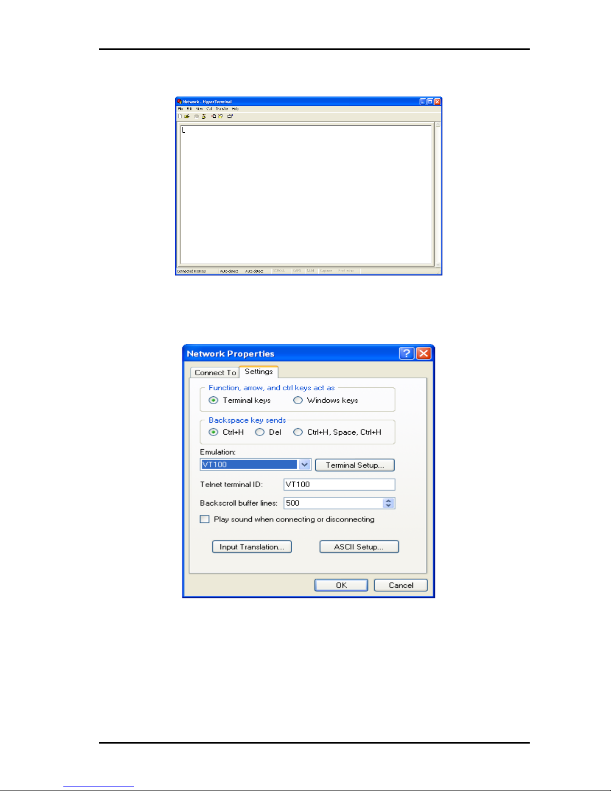
5. Click Properties in the HyperTerminal window to enter the Network
Properties dialog box. Click the Settings tab, set the emulation to
VT100, and then click OK.
Figure 28: Terminal emulation setting
Page 30

eMerge EM-GE Ethernet Media Router Rev. A
nevion.com | 30
4.3 Router Power-On
After the switch is powered on and starts up, self-check information on equipment will display
on the terminal. Users are prompted to type Enter after self-check, then command line DOS
prompts (such as (Router)) will appear.
Type a command, configure Ethernet switches or view the running state of Ethernet Rotuer.
Enter "?" whenever you need a help. See the subsequent chapters of this manual for specific
configuration commands.
Page 31

eMerge EM-GE Ethernet Media Router Rev. A
nevion.com | 31
5 Router Software Loading
The traditional switch software loading is serial loading, but it is slow and time-consuming,
and it cannot realize remote loading and is inconvenient for operation. To address these
problems, TFTP module is introduced to switch to facilitate software loading and file
download via Ethernet. Specific operations are as follows:
Step 1: Enter uBoot operation mode
To enter uBoot operation mode, press the combined key Ctrl + b during the
switch startup when Press ctrl + b to stop autoboot: is prompted; startup information
is as follows:
Restarting system.
U-Boot 3.0.2 (Development build) (Build time: May 10 2011 - 17:14:19)
CN5010_CTC board revision major:1, minor:0, serial #:
OCTEON CN5020-SCP pass 1.1, Core clock: 500 MHz, DDR clock: 265 MHz (530 Mhz
data rate)
Board descriptor tuple not found in eeprom, using defaults
DRAM: 256 MB
Clearing DRAM...... done
Flash: 64 MB
BIST check passed.
Net: octeth0, octeth1
Press ctrl+b to stop autoboot: 3 – Press Ctrl + b to enter uBoot operation mode
Step 2: Identify a PC as loading server, connect the administration port of switch and
the PC with net line; set IP address of the PC and administration IP address of the
switch for the same network segment; specific operations are as follows:
-
Use the command help open_all to open all commands;
-
Use the command setenv ipaddr address to set the administration IP address of the
switch; the switch will copy image files to the switch from TFTP server using this
address;
-
Use the command setenv serverip address to set the IP address of TFTP server; the
switch will copy image files from this TFTP server;
-
Use the command ping to check if the switch communicates with the loading server;
-
Can use the command printenv to view the current environment variables of switch;
-
Can use the command saveenv to save the current environment variables of switch
to EPROM;
-
Can use the command reenv to restore the environment variables of switch to default
value.
Step 3: Run TFTP Server program on PC as a server, and set the directory where
loading files are located; uBoot file supposed to be upgraded is u_boot_v1.0.bin.
Step 4: Run the command upgrade_uboot u_boot_v1.0.bin to upgrade uBoot; here
the filename is u_boot_v1.0.bin.
Step 5: Run the command reset to complete the upgrade of uBoot.
Page 32

eMerge EM-GE Ethernet Media Router Rev. A
nevion.com | 32
6 Upgrade of Operating System
eMERGE EM-GE Series Ethernet Media Router can support new features and enhance
system performance without replacing hardware by upgrading the operating system.
Figure 29: Upgrade Operating System
Step 1: Copy the upgrading mirror to switch
1. In the privilege mode of switch, use the command COPY to copy the
mirror files on TFTP server to the boot directory of switch flash.
Router# copy mgmt-if tftp://10.10.29.160/RouterOS-ma-
v3.1.12.it.r.bin flash:/boot/ RouterOS-ma-v3.1.12.it.r.bin
2. When copying, check if the switch has enough space; if the space is
not enough, you can delete redundant mirror.
Step 2: Set the mirror that will be loaded when switch starts next time
1. After copying the mirror to a relevant directory of switch, you can use
the command boot to set the mirror that will be loaded when switch
starts next time;
Router(config)# boot system flash:/boot/RouterOS-ma-
v3.1.12.it.r.bin
Step 3: View the mirror that will be loaded when switch starts next time
After setting the mirror that will be loaded when switch starts next time, you
can use the command SHOW to check if the setting is valid;
Router# show boot images
System image files list:
Current boot image version: 3.1.12
Create Time Version File name
================================================================
======
2011-01-01 15:03:30 3.1.11 RouterOS-ma-v3.1.11.it.r.bin
* 2011-05-28 10:08:38 3.1.12 RouterOS-ma-v3.1.12.it.r.bin
Among them, the files marked with * are image files that will be loaded when
switch starts next time.
Page 33

eMerge EM-GE Ethernet Media Router Rev. A
nevion.com | 33
7 Maintenance and Troubleshooting
7.1 Loading Failure Processing
After loading fails, the system will keep running in the original version. At this time, users
should re-check if physical port connections are good firstly. If some ports are not connected,
then re-connect them to ensure that physical connections are correct, and begin re-loading.
If physical connections are correct, then check the loading process information displayed on
the super terminal to verify if there are input errors. If there are input errors, correct them and
re-load. For example, when using TFTP protocol, we enter incorrect IP addresses of Server
and Router, name of loading software, do not specify the correct working path of correct
TFTP server and so on; if physical connections are good, and there are no input errors in the
loading process but the loading fails finally, please contact agents for help.
7.2 User Password Lost
If system password is lost or forgotten, the following method can be used to reset
password:
-
Enter uBoot operation mode; see Chapter 5 for how to enter.
-
Input boot_flash_nopass command to start system in uBoot mode.
After using boot_flash_nopass command, system will clear up the startup-config files;
before starting this operation, the startup-config files will be stored in flash:/startup-
config.conf.old file.
7.3 Power System Troubleshooting
Router can judge if its power system is faulty according to the PWR indicator on the front
panel: when power system works normally, the PWR indicator shall always keep lighting;
when the PWR indicator is off, please check if:
-
The power line of switch is connected correctly.
-
EPS of switch matches the power required by switch.
7.4 Configuration System Troubleshooting
After the switch is powered on, if system is normal, the startup information will be displayed on
the configuration terminal; If the configuration system is faulty, the configuration terminal may
display no information or hashes.
No information on the terminal
After power-on, if no display information on configuration terminal appears, please check if:
Step 1: The power is normal.
Step 2: The cable of configuration port (Console) is properly connected.
If no problems have been found after the above checks, it is possible that
configuration cable is faulty or the parameter setting of terminal (such as super
terminal) are incorrect, please check accordingly.
Page 34

eMerge EM-GE Ethernet Media Router Rev. A
nevion.com | 34
Step 3: Troubleshooting for the terminal displaying hashes:
If the configuration terminal displays hashes, it is probable that the parameter setting
of terminal (such as super terminal) are incorrect Please confirm the parameter setting
of terminal (such as super terminal): baud rate: 9600, data bit: 8, parity: no, stop
bit: 1, flow control: NA, selecting terminal emulation: VT100.
Page 35

eMerge EM-GE Ethernet Media Router Rev. A
nevion.com | 35
General environmental requirements for Nevion equipment
1.
The equipment will meet the guaranteed performance specification under the
following environmental conditions:
-
Operating room temperature
range:
0°C to 45°C
-
Operating relative humidity range:
<95% (non-condensing)
2.
The equipment will operate without damage under the following environmental
conditions:
-
Temperature range:
0°C to 45°C
-
Relative humidity range:
<95% (non-condensing)
Page 36

eMerge EM-GE Ethernet Media Router Rev. A
nevion.com | 36
Product Warranty
The warranty terms and conditions for the product(s) covered by this manual follow the
General Sales Conditions by Nevion, which are available on the company web site:
www.nevion.com
Page 37

eMerge EM-GE Ethernet Media Router Rev. A
nevion.com | 37
Appendix A Materials declaration and recycling
information
A.1 Materials declaration
For product sold into China after 1st March 2007, we comply with the “Administrative Measure
on the Control of Pollution by Electronic Information Products”. In the first stage of this
legislation, content of six hazardous materials has to be declared. The table below shows the
required information.
組成名稱
Part Name
Toxic or hazardous substances and elements
鉛
Lead
(Pb)
汞
Mercury
(Hg)
镉
Cadmium
(Cd)
六价铬
Hexavalent
Chromium
(Cr(VI))
多溴联苯
Polybrominated
biphenyls
(PBB)
多溴二苯醚
Polybrominated
diphenyl ethers
(PBDE)
eMERGE EM-GE
Ethernet Media Router
O O O O O
O
Power supply
O O O O O
O
O: Indicates that this toxic or hazardous substance contained in all of the homogeneous materials for this part is
below the limit requirement in SJ/T11363-2006.
X: Indicates that this toxic or hazardous substance contained in at least one of the homogeneous materials used
for this part is above the limit requirement in SJ/T11363-2006.
This is indicated by the product marking:
A.2 Recycling information
Nevion provides assistance to customers and recyclers through our web site
http://www.nevion.com/. Please contact Nevion’s Customer Support for assistance with
recycling if this site does not show the information you require.
Where it is not possible to return the product to Nevion or its agents for recycling, the following
general information may be of assistance:
Before attempting disassembly, ensure the product is completely disconnected from
power and signal connections.
All major parts are marked or labeled to show their material content.
Depending on the date of manufacture, this product may contain lead in solder.
Some circuit boards may contain battery-backed memory devices.
 Loading...