

Page 1

RNS® System Programming Manual
For the RNS® Tablet Model 5000 and the
Patient Data Management System (PDMS) Model 4340
18 NeuroPace, Inc.
© 20
DN 1017919 Rev 2
Rev Date: 2018-06
Page 2

ii
ABOUT THIS MANUAL
This manual includes instructions for use for:
®
• The RNS
• The NeuroPace
Note: The RNS
RNS-300M and model RNS-320.
Note: The term “programmer” as used in this manual is a generic term that refers to either the
RNS
Note: Images in this manual are representative and may vary in detail from what a particular user
experiences.
Tablet model 5000 with software version 1.8
®
Patient Data Management System model 4340
®
Tablet model 5000 is compatible with the RNS® Neurostimulator model
®
Tablet or the NeuroPace® Programmer (laptop computer).
RNS® System Programming Manual
Page 3

iii
FCC INFORMATION
The following is communications regulation information on the neurostimulator models RNS-300M and
RNS-320,and wand model W-02.
• Neurostimulator model RNS-300M FCC ID: WBWRF300
• Neurostimulator model RNS-320 FCC ID: WBWRF320
• Wand FCC ID: WBW902
These components comply with Part 15 of the FCC Rules. Operation is subject to the following two
conditions: (1) These devices may not cause harmful interference, and (2) these devices must accept any
interference received, including interference that may cause undesired operation.
IMPORTANT: Changes or modifications to these components not expressly approved by NeuroPace, Inc.
could void the FCC Certification, and negate your auth or it y to operate them.
This equipment complies with FCC radiation exposure limits set forth for an uncontrolled environment.
This transmitter must not be co-located or operati ng in conjunc tio n with any other antenna or transmitter.
RNS® System Programming Manual
Page 4
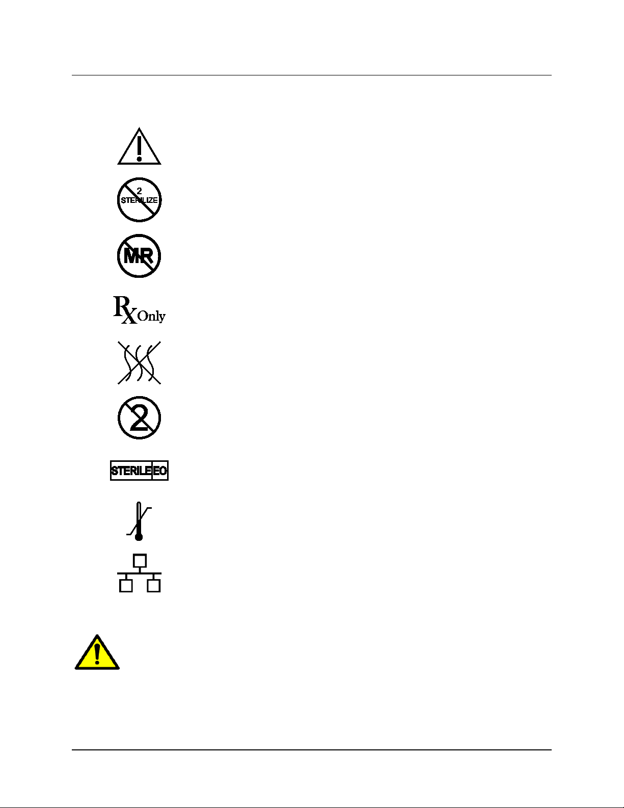
SYMBOLS
Explanation of symbols on product or package labeling
Caution
D
o Not Resterilize
Unsafe
MR
Prescription Only
iv
N
on-Pyrogenic
ingle Use
S
terilized Using Ethylene Oxide
S
T
emperature Limits
E
thernet Connection (Network Connection)
Proposition 65, a State of California voter initiative, requires the following notice:
WARNING: This product can expose you to chemicals including ethylene oxide, which is
known to the State of California to cause cancer an d birth defects or other reproductive harm.
For more information go to www.P65Warnings.ca.gov.
RNS® System Programming Manual
Page 5

1
TABLE OF CONTENTS
ABOUT THIS MANUAL ......................................................................................................II
FCC INFORMATION ........................................................................................................ III
SYMBOLS ..................................................................................................................... IV
INTRODUCTION ............................................................................................................. 4
DEVICE DESCRIPTION ..................................................................................................... 4
®
RNS
NEUROPACE
PRODUCTS AND ACCESSORIES ....................................................................................... 4
CONTACTING NEUROPACE ............................................................................................. 5
TYPOGRAPHIC CONVENTIONS ......................................................................................... 5
WARNINGS AND CAUTIONS – PROGRAMMER .................................................................... 6
STERILIZATION AND STORAGE ........................................................................................ 8
TABLET ............................................................................................................... 4
®
PATIENT DATA MANAGEMENT SYSTEM ...................................................... 4
Product Storage .................................................................................................................................... 8
Explant and Disposal ............................................................................................................................ 8
Wand Cleaning and Sterilization .......................................................................................................... 8
Electrostatic Discharge (ESD) / Static Electricity ................................................................................. 9
RNS® TABLET INSTRUCTIONS .................................................................................. 10
POWER ON THE TABLET ............................................................................................... 10
CONNECT AND LOGIN OVERVIEW .................................................................................. 10
FUNCTIONALITY WITH AND WITHOUT A PDMS CONNECTION ............................................ 11
CONNECT TO THE INTERNET FOR PDMS ACCESS ........................................................... 11
Mobile Broadband Works Automatically............................................................................................. 11
Steps to Connect to a Wi-Fi Network ................................................................................................. 12
If You Lose Network Connectivity ...................................................................................................... 13
LOG IN TO THE RNS
®
TABLET ...................................................................................... 14
LOG IN TO THE PDMS .................................................................................................. 15
INTERROGATE THE RNS
®
NEUROSTIMULATOR ............................................................... 16
DATA RETENTION AND ACCESS ON THE NEUROSTIMULATOR, PROGR AMME R AND PDMS . 17
Programmed Settings ......................................................................................................................... 17
Storage of ECoGs and Neurostimulator Activity (Diagnostics) .......................................................... 17
HOME SCREEN ............................................................................................................ 18
NEUROSTIM INFO SCREEN ............................................................................................ 20
Electrode Impedance and Battery Voltage ......................................................................................... 22
ACTIVITY SCREEN ........................................................................................................ 23
Activity Histogram Viewing Options .................................................................................................... 24
View Neurostim Settings .................................................................................................................... 25
View Event List ................................................................................................................................... 28
Types of Reports ................................................................................................................................ 28
RNS® System Programming Manual
Page 6

2
Advanced Views ................................................................................................................................. 29
ECOG LIBRARY SCREEN .............................................................................................. 29
LIVE ECOGS SCREEN .................................................................................................. 31
CREATE THE RECORDING MONTAGE ............................................................................. 32
Identifying Ports, Leads and Electrodes on the Neurostimulator ....................................................... 33
Creating the Montage ......................................................................................................................... 34
Recommended Initial Montage Settings............................................................................................. 35
Program the Neurostimulator with the New Settings ......................................................................... 37
SET UP ECOG CAPTURE .............................................................................................. 38
Selecting ECoG Capture Settings ...................................................................................................... 38
Recommended Initial ECoG Capture Settings ................................................................................... 41
Program the Neurostimulator with the New Settings ......................................................................... 43
RECOMMENDATION FOR REVIEW OF INITIAL ECOG CAPTURE SETTINGS .......................... 43
CONFIGURE PATTERN DETECTION: DEFINE AND MODIFY DETECTION SETTINGS ............... 44
Phase 1: Select a Default Detection Set upon First Use.................................................................... 45
Phase 2: Define a Pattern Detection Set ........................................................................................... 48
Phase 3: Customize Pattern Detection .............................................................................................. 52
DETECTION TOOLS AND DETECTORS ............................................................................. 56
Detection Tools and Detectors ........................................................................................................... 56
Power Change Detector ..................................................................................................................... 57
Rhythmic Activity Detector ................................................................................................................. 59
Spike Activity Detector ....................................................................................................................... 60
Bandpass Detection Tool ................................................................................................................... 61
Area Detection Tool ............................................................................................................................ 62
Advanced Controls ............................................................................................................................. 63
SHARE AND/OR DOWNL OAD A DETECTION SET .............................................................. 64
Steps to Share a Detection Set .......................................................................................................... 64
Steps to Download a Detection Set to the Tablet .............................................................................. 66
OVERVIEW OF RESPONSIVE THERAPY ........................................................................... 69
CONFIGURE RESPONSIVE THERAPY .............................................................................. 70
Optional Advanced Settings ............................................................................................................... 74
Test Stimulation Before Enabling ....................................................................................................... 77
Enable Therapy: Review & Program .................................................................................................. 78
Recommended Initial Responsive Therapy Settings ......................................................................... 79
Recommended Therapy Modifications After Observing Clinical Response....................................... 80
EXPORT AND IMPORT DEVICE SETTINGS FOR NEUROSTIMULATOR REPLACEMENT ............ 81
Transfer Compatibility......................................................................................................................... 81
Export Neurostimulator Set tings ......................................................................................................... 81
Import Neurostimulator Settings ......................................................................................................... 82
PATIENT LIST ON TABLET AND THE PDMS ON A PERSONAL COMPUTER ........ 84
PDMS ACCESS ON A PERSONAL COMPUTER ................................................................. 85
PDMS PROFILE AND SETTINGS .................................................................................... 85
PATIENT & NEUROSTIM INFO ........................................................................................ 88
NEUROSTIM SETTINGS.................................................................................................. 88
RNS® System Programming Manual
Page 7

3
ACTIVITY ..................................................................................................................... 90
ECOG LIBRARY ........................................................................................................... 90
LIVE ECOGS ............................................................................................................... 90
PATIENT FOLLOW-UP ACTIVITIES ............................................................................ 91
TROUBLESHOOTING .................................................................................................. 92
Network Connectivity Problems ......................................................................................................... 92
Abnormal Lead Impedance (greater than 3500 Ohms or less than 250 Ohms) ................................ 92
Insufficient Charge.............................................................................................................................. 95
Noise, Artifacts, Poor Signal Displayed, or No Signal Displayed in Live ECoG................................. 95
Poor or No Communication Between the RNS® Neurostimulator and the RNS® Tablet ................... 96
Tablet Does Not Turn On ................................................................................................................... 97
Tablet Freezes or Does Not Turn Off ................................................................................................. 97
Tablet Shuts Down ............................................................................................................................. 97
Impedance Measurement Was Rejected / Test Request Was Rejected ........................................... 97
SPECIFICATIONS AND CHARACTERISTICS ............................................................ 98
®
RNS
TABLET ............................................................................................................. 98
TABLET WIRELESS ....................................................................................................... 98
®
RNS
SYSTEM WIRELESS ............................................................................................ 99
ELECTROMAGNETIC EMISSIONS AND IMMUNITY .............................................................. 99
Hospital or Medical Environments ...................................................................................................... 99
Home, Work or Public Environments ............................................................................................... 100
Guidance and Manufacturer’s Declaration ....................................................................................... 100
Emissions and Immunity Information ............................................................................................... 101
GLOSSARY ................................................................................................................ 105
INDEX ......................................................................................................................... 110
RNS® System Programming Manual
Page 8
Introduction 4
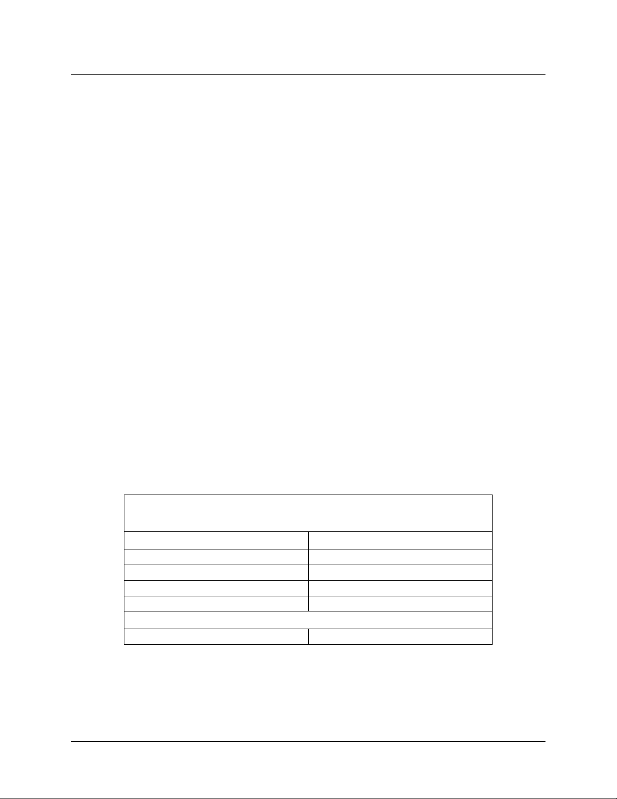
Item
Model Number
RNS® Tablet (with attached case)
5000
Stylus
AC Adapter
Carrying Bag
Used With
Wand
W-02
INTRODUCTION
DEVICE DESCRIPTION
• RNS® Tablet model 5000 with software version 1.8
®
• NeuroPace
®
RNS
TABLET
Patient Data Management System model 4340
The RNS® Tablet includes a tablet computer that runs proprietary NeuroPace software, and uses custom
telemetry components to communicate with the RNS
®
Neurostimulator. Clinicians can use the tablet to
program how the neurostimulator operates. Settings include, but are not limited to, the implanted system
configuration, detection settings adapted to the patient's ECoG patterns
storage, and settings of the therapies. Clinicians can also use the tablet to review previously retrieved
neurostimulator activity information, perform detection analysis, and communicate with the NeuroPace
, settings for ECoG record
®
Patient Data Management System (PDMS) via the Internet.
Note: The term “programmer” as used in this manual is a generic term that refers to either the
®
RNS
Tablet or the NeuroPace® Programmer (laptop computer).
NEUROPACE
®
PATIENT DATA MANAGEMENT SYSTEM
The Patient Data Management System (PDMS) maintains patient and product data obtained from the
programmer and remote monitor. Authorized users may access the PDMS via the Internet using a
personal computer. An electronic signature in the form of a username and password are required for user
authentication.
PRODUCTS AND ACCESSORIES
Note: Manuals and other literature are not listed below.
RNS® Tablet Kit
Model 5001
RNS® System Programming Manual
Page 9
Introduction 5
This manual contains information applicable to the RNS® Tablet, which is used to program how
the RNS
®
Neurostimulator operates. It includes information about the secure Patient Data
Management System (PDMS) database, which is accessible using the tablet or a web browser
on a personal computer.
Refer to the RNS
®
System manual for additional device descriptions, device specifications, and
indications for use, contraindications, warnings, cautions, and instructions for use.
®
All NeuroPace
manuals are available at www.NeuroPace.com or by contacting NeuroPace,
Inc. (see Contacting NeuroPace on page 4). Refer to the clinical summary booklet for information on the clinical study results of the RNS
System and advers e event dat a.
CONTACTING NEUROPACE
All questions or concerns regarding the NeuroPace® RNS® System should be forwarded to:
NeuroPace, Inc.
455 N. Bernardo Ave.
Mountain View, CA 94043
Customer Support: 866-726-3876 (Toll Free in the United Stat es )
Website: www.neuropace.com
®
TYPOGRAPHIC CONVENTIONS
This manual uses the following typographic conventions.
WARNING: W
Caution: Caution Title
Note: Notes provide additional information.
1. Numbered lists are used to identify a sequence of steps.
This format is used to identify figure titles and descriptions
BOLD SMALL CAPS indicate on-screen text, like the names of screens, buttons and fields.
Note: Software version numbers found on screenshots in this manual are provided for illustrative
purposes only and may not be the same as the version number you see on screen.
ARNING TITLE
Warnings alert you to serious adverse events and potential safety hazards and
situations that may cause injury.
Cautions alert you to exercise special care.
RNS® System Programming Manual
Page 10

Introduction 6
WARNINGS AND CAUTIONS – PROGRAMMER
Note: See the RNS® System manual for warnings and cautions regarding other components of
the RNS
WARNING: P
®
System.
HYSICIAN AND CENTER ACCESS TO THE RNS® SYSTEM
®
The RNS
System should only be implanted by neurosurgeons with adequate
experience in the implantation of subdural and stereotactic implantation of
intraparenchymal electrodes and in the surgical treatment of intractable epilepsy. The
®
RNS
System should only be used by neurologists or neurosurgeons with adequate
experience in the management of intractable epilepsy and in the localization of
epileptic foci, including the use of scalp and intracranial electrodes.
Neurologists and neurosurgeons using the RNS
NeuroPace
RNS
®
®
RNS® System training program. To qualify to manage patients with the
System, physicians must demonstrate specific expertise related to epilepsy,
®
System must have completed the
video-EEG monitoring, interpretation of electrocorticograms (ECoGs), the
pharmacology of antiepileptic medications and selection of patients for epilepsy
surgery. Implantation of the RNS
®
System should be performed only by qualified
neurosurgeons at centers capable of providing comprehensive epilepsy care, i.e.
“Comprehensive Epilepsy Centers.” These centers should have the expertise to
provide diagnostic services that include video-EEG monitoring with scalp and
intracranial electrodes and neuroimaging, and are experts in the treatment of epilepsy
with antiepileptic medications, epilepsy surgery, and devices.
WARNING:
MANAGEMENT OF PATIENTS WITH THE RNS® SYSTEM BY PHYSICIANS AT CENTERS THAT DO
NOT PROVIDE THE SERVICES PROVIDED AT COMPREHENSIVE EPIL EPSY CENTERS
WARNING: P
WARNING: R
In some instances, post-implant programming may be conducted by neurologists
meeting the experience and certification requirements for neurologists at
Comprehensive Epilepsy Centers, but who are not practicing in such centers. This
situation might occur if the patient is not able to travel to a Comprehensive Epilepsy
Center for regular follow-up (e.g. because of distance from the Center or limited
access to transportation). These neurologists will be qualif ied b y NeuroPac e to provide
post-implant programming. After NeuroPace
®
RNS® System training is complete, the
qualified programming neurologist may receive external NeuroPace products
(programmer, remote monitor).
OTENTIAL SHOCK
Submerging any part of the programmer, or operating the programmer in or near a wet
environment, may result in an electrical shock.
The programmer must be disconnected from the electrical outlet prior to cleaning to
avoid the potential of electrical shock.
Electrical shock may occur if the programmer AC adapter and power cord are not
properly connected to a grounded power source.
ADIO FREQUENCY IDENTIFICATION (RFID) INTERFERENCE
Sources of RFID can result in signals that appear as ECoG activity to the
neurostimulator. Signals that appear as ECoG activity could also result in delivering
RNS® System Programming Manual
Page 11

Introduction 7
the programmed stimulation to the patient (per the device detection programming).
The physician should be aware of possible sensing artifacts when assessing the
ECoG recordings. Potential sources of RFID may occur in a health care environment,
retail stores, public libraries, airports and business environments.
Refer to Electromagnetic Emissions and Immunity on page 99 for more
information.
WARNING: S
WARNING: N
WARNING: P
ECURITY AND ELECTRONIC TRACKING SYSTEMS
Security screening devices (such as theft detectors, security tag deactivators, and
airport security screening devices) can result in signals that appear as ECoG activity to
the neurostimulator. Signals that appear as ECoG activity could also result in
delivering the programmed stimulation to the patient (per the device detection
programming). Such devices may be found at retail stores, public libraries and
airports. The physician should be aware of possible sensing artifacts when assessing
the ECoG recordings. Patients should be instructed to walk through the center of such
security screening units without stopping, when possible, and exit the area of the
screening device as soon as possible.
EUROPACE COMPONENTS
Use of accessories, transducers, and cables other than those pro vided b y Neur o Pace
could result in increased electromagnetic emissions or decreased electromagnetic
immunity of the RNS
ORTABLE AND MOBILE RADIO FREQUENCY (RF) COMMUNICATIONS EQUIPMENT
®
System and result in improper operation.
Portable and mobile RF communications equipment (including peripherals such as
antenna cables and external antennas) should be used no closer than 12 inches (30
cm) to any part of the RNS
performance of the RNS
®
System, including cables. Otherwise, degradation of the
®
System could result.
WARNING: N
EUROPACE® EQUIPMENT PLACEMENT
®
Use of NeuroPace
to or stacked with other equipment should be avoided because it could result in
improper operation. If such use is necessary, the NeuroPace
equipment (for example, remote monitor or programmer) adjacent
®
equipment and other
equipment should be observed to verify that the y are operati ng normally.
Caution: Telemetry Artifact
Telemetry may produce an electrographic artifact. If responsive therapy is enabled
with a sensitive detection set, detection of the electrographic artifact may occur
resulting in therapy delivery. The physician should be aware of possible sensing
artifacts when assessing the ECoG recordings.
Caution: Afterdischarge Activity
If evidence of afterdischarge activity resulting from stimulation is seen either on stored
ECoGs or during test stimulation delivery, stimulation parameters should be adjusted
to prevent such occurrence.
RNS® System Programming Manual
Page 12
Introduction 8
Caution: Programmer Failure
As with any electronic device, the programmer may be damaged or malfunction if the
programmer AC adapter and power cord are not properly connected to a grounded
power source.
Caution: Incompatibility of Programmer with Other Medical Devices
The effects of using the programmer to interrogate other electronic, programmable
devices such as pacemakers, defibrillators, cochlear implants, and other
neurostimulators or CPAP machines are unknown. It could result in reprogramming of
the other device and therefore, the physicians familiar with each device should check
the programmed parameters of each device before the patient is discharged and after
each programming session of either device.
Caution: Electronic Interference
Communications between the programmer and the implanted neurostimulator may be
interrupted by emissions from nearby electronic devices. Examples of sources of EMI
are lithotripsy, computer monitors, cellular telephones, motorized wheel chairs, x-ray
equipment and other monitoring equipment. Interruption of telemetry can result in
incomplete communication. If EMI disrupts programming, move the programmer away
from the likely source of EMI. Refer to Poor or No Communication Between the
®
RNS
Neurostimulator and the RNS® Tablet (page 96) for more information.
Caution: Placement of the Programmer Power Cord
Make sure nothing rests on the programmer power cord and that the cord is not
located where it can be tripped over or stepped on.
Caution: Heating
The programmer’s AC adapter may become hot during normal operation. Use care
when handling during or immediately after operation.
STERILIZATION AND STORAGE
Product Storage
Components should be stored in a clean and secure area with a room temperature of approximately
14 to 28 degrees Celsius.
Explant and Disposal
Program all detection and therapy functions to DISABLED prior to explanting and shipping the RNS
Neurostimulator. Return the explanted neurostimulator and leads to NeuroPace. NeuroPace will
provide shipping containers if requested.
DO NOT incinerate the neurostimulator; explosion can occur if the neurostimulator is exposed to
incineration or cremation temperatures.
®
Wand Cleaning and Sterilization
The wand can be cleaned by wiping with water. It can be placed in a sterile bag for use in the sterile
field. DO NOT STERILIZE the wand.
RNS® System Programming Manual
Page 13

Introduction 9
Electrostatic Discharge (ESD) / Static Electricity
The ports on the tablet may be sensitive to electrostatic discharge / static electricity. Handle the tablet
ports carefully. If exposed to electrostatic discharge, the tablet may experience telemetry artifacts or
errors, or may freeze. In the event of a tablet freeze, refer to Tablet Freezes
on page 97.
RNS® System Programming Manual
Page 14

Tablet Instructions 10
RNS
This chapter primarily addresses use of the tablet during an interactive programming session, that is,
when the clinician uses the wand for communication between the neurostimulator and tablet. For
information on using the PDMS apart from an interactive programming session, either using the tablet or
using a web browser on a personal computer, see Patient List on Tablet and the PDMS on a Personal
Computer on page 84.
®
TABLET INSTRUCTIONS
POWER ON THE TABLET
When interacting with a patient, the tablet should be used on battery power only. Make sure the tablet is
sufficiently charged for use before powering on.
Press and hold the power button on the upper right side of the tablet. After 2-3 seconds, the tablet beeps
to indicate it is powering on.
CONNECT AND LOGIN OVERVIEW
Access to all of the functionality of the tablet requires an Internet connection and two logins, in this order:
1. Connect to the Internet via Wi-Fi or mobile broadband on the tablet. Mo bi le broa dban d works
automatically. To connect to Wi-Fi, see Steps to Connect to a Wi-Fi Network on page 12.
Alternatively, the tablet computer can also support use of a docking station that has an Ethernet
connector (wired connection). Contact NeuroPace customer service if you prefer this alternative.
2. Login to the tablet. NeuroPace provides the initial username and password for this login.
3. Login to the Patient Data Management System (PDMS), which requires the Internet
connection established in the first step. NeuroPace also provides the initial username and
password for the PDMS. (For PDMS access using a personal computer, select the PDMS link at
www.neuropace.com and log in. For further instructions, see
Computer on page 85.)
Note: Programming functions that are typically performed in the operating room do not require an
Internet connection to the PDMS.
You can access all programming functions without connection to the PDMS except the following:
• View stored information such as ECoGs, neurostimulator activity and settings for any patient
• Make a new detection set or adjust parameters of a detection set
For details, see Functionality with and without a PDMS Connection on page 11.
PDMS Access on a Personal
RNS® System Programming Manual
Page 15
Tablet Instructions 11
FUNCTIONALITY WITH AND WITHOUT A PDMS CONNECTION
Note: Programming functions that are typically performed in the operating room do not require an
Internet connection to the PDMS.
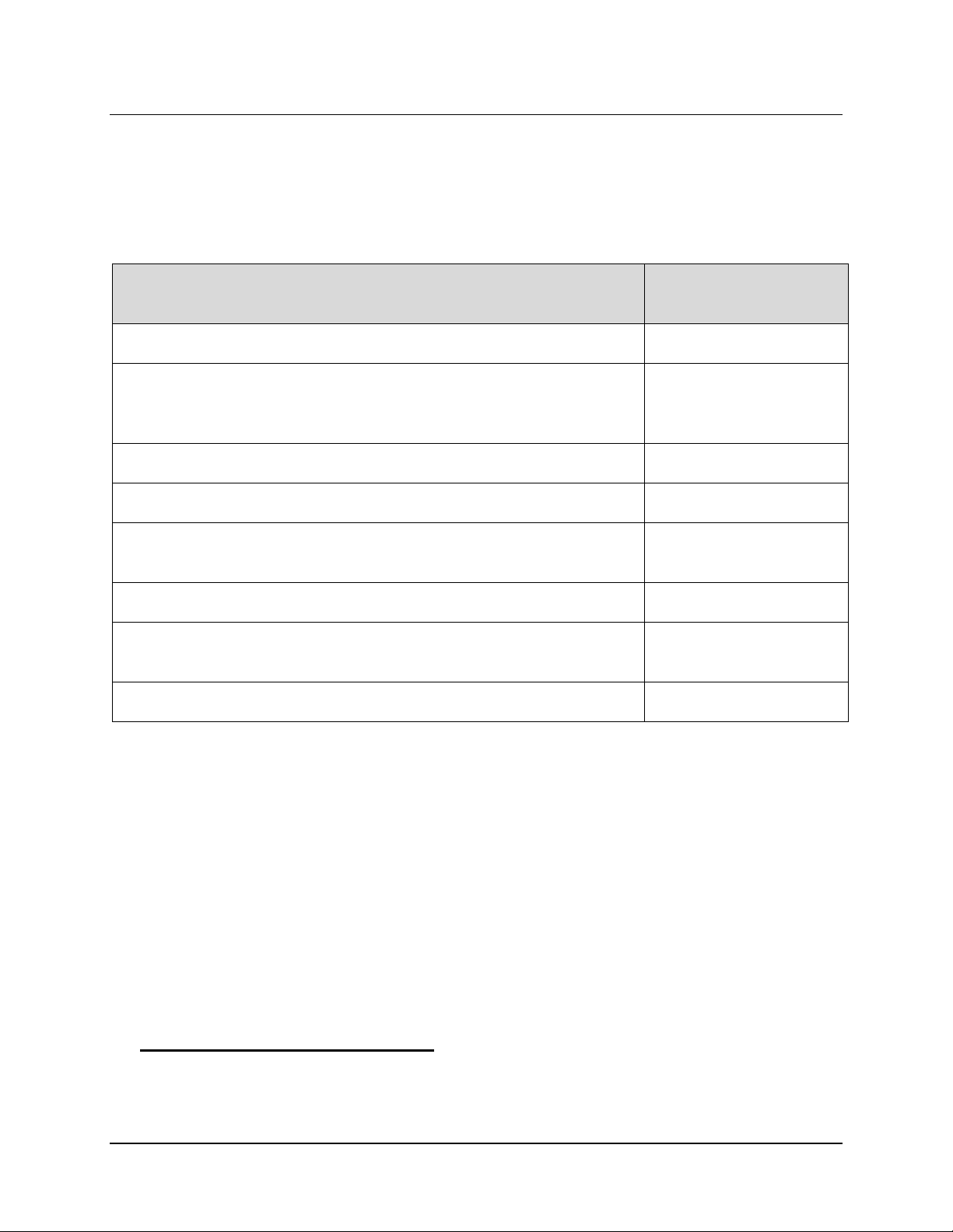
The table below identifies the tablet functions that do not require an Internet connection to the PDMS and
those that do.
Function Internet Connection to
the PDMS Required
Interrogate the neurostimulator No
View neurostimulator information and settings downloaded during current
No
session, including battery voltage, impedance, stimulation settings,
recording montage
Create or change the recording montage No
Set up or adjust ECoG capture settings No
Select and program a default detection set or a custom detection set
No
previously saved to the tablet from the PDMS
Select and program all stimulation settings No
View stored information such as ECoGs, neur ostimulator activity and
Yes
settings for any patient
Make a new detection set or adjust parameters of a detection set Yes
CONNECT TO THE INTERNET FOR PDMS ACCESS
When connected to the Internet and logged in to the Patient Data Management System (PDMS), the
®
RNS
Tablet provides a look-through to the information stored on the PDMS, such as ECoGs,
neurostimulator settings and activity. The PDMS is a patient database integrated with the RNS
the PDMS is also available using a browser on an y Internet-connected computer. The tablet ships with
Wi-Fi enabled, so it can detect available Wi-Fi networks out of the box.
®
Tablet;
Note: If you attempt to connect to a Wi-Fi network that requires you to go to an Internet website to
log in, as in some hotels and coffee shops, you will not be able to log in because the tablet does
not have an Internet browser program. As a medical device, its Internet connectivity is restricted
to the PDMS only.
The tablet ships with Wi-Fi and mobile broadband enabled.
Mobile Broadband Works Automatically
Mobile broadband is pre-configured by NeuroPace to be on and working, so no further effort is
necessary and the tablet will connect to mobile broadband automatically if a signal is available.
RNS® System Programming Manual
Page 16
Tablet Instructions 12
Steps to Connect to a Wi-Fi Network
Follow these steps to connect via Wi-Fi to the Internet on the RNS® Tablet.
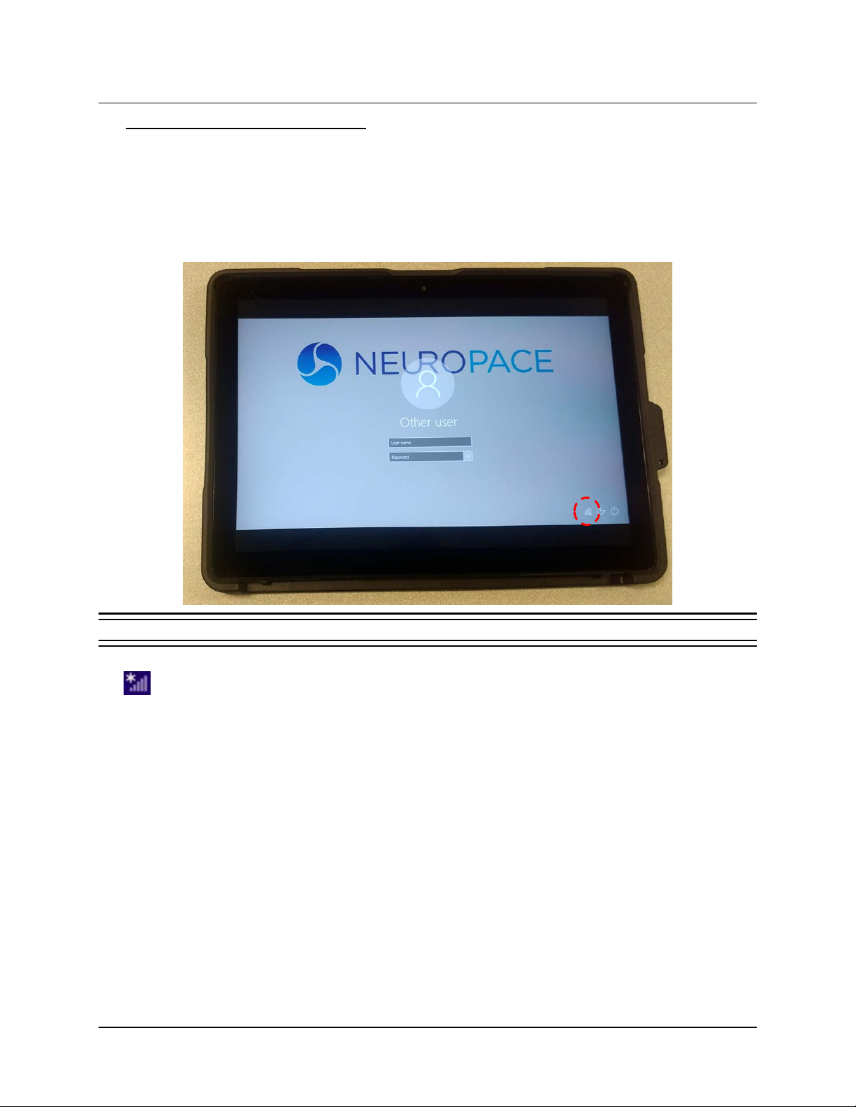
1. The tablet login screen appears first upon startup. Select a user. The screen prompts you for
a username and password and displays the keyboard, but ignore these for now.
2. Touch to select the small symbol that indicates network status. (If necessary, touch outside
the login fields to dismiss the keyboard and see the whole screen.)
Figure 1 Touching the network icon at lower left
When a wireless network is available, it looks like the signal strength symbol with an asterisk
above it. A different symbol is present if there is no wireless network available. Select it in any
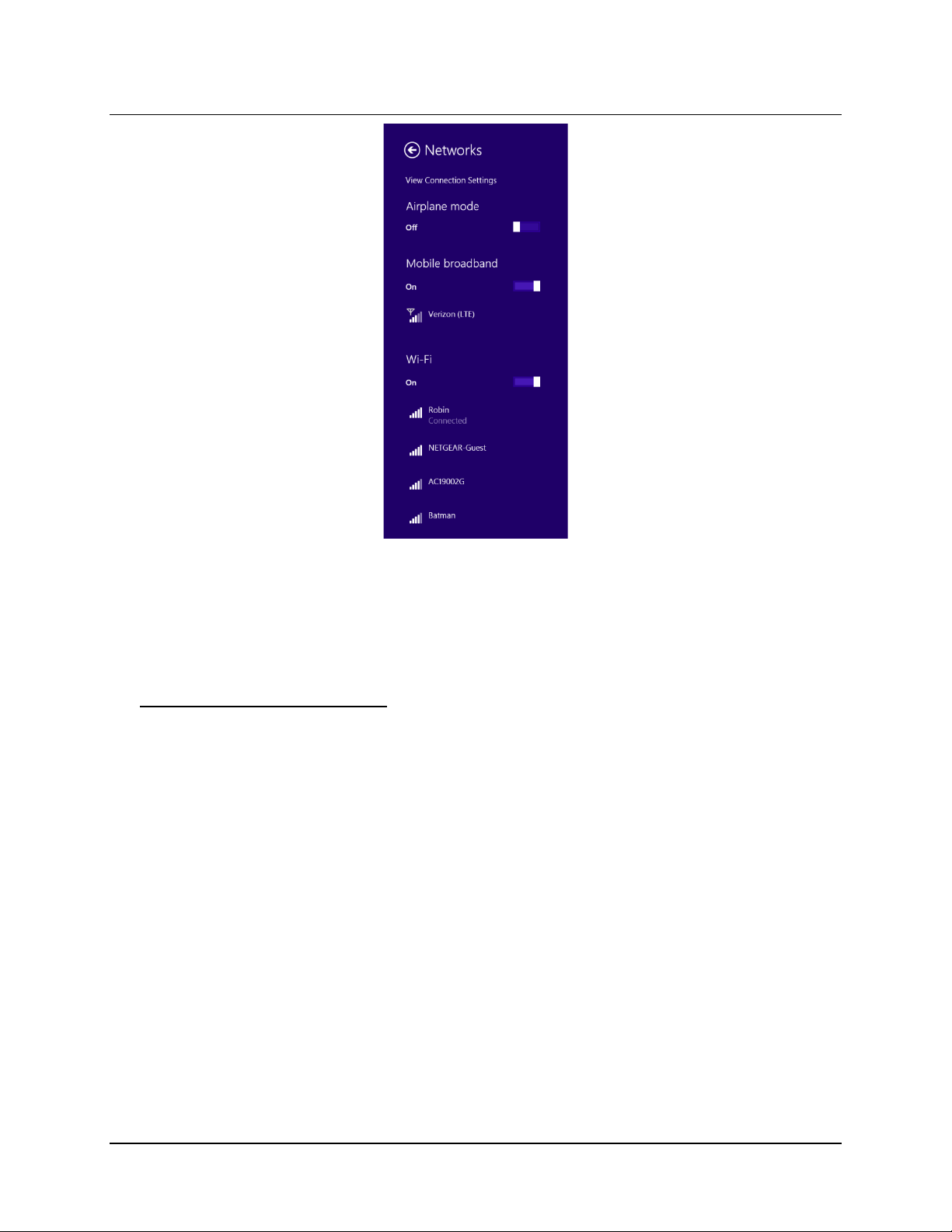
case to open the N
ETWORKS panel on the right side of the screen.
RNS® System Programming Manual
Page 17
Tablet Instructions 13
3. From this point, Wi-Fi access is the same as on a smartphone or laptop computer:
a. Select the desired network and then select C
b. Enter the network security key and select N
ONNECT.
EXT. (The security key is your Wi-Fi
password.) The tablet connects if the security key is correct. Internet connection is
complete.
If You Lose Network Connectivity
If you lose network connectivity, you will not lose information you already programmed into the
neurostimulator or saved to the PDMS, but you will lose information not already programmed into the
neurostimulator or saved to the PDMS.
If you are already logged in to the tablet and have lost network connectivity, first log off to return to
the login screen: return to the Home screen and touch the circle-X (exit) button at upper right, and
then select E
XIT on the PROGRAMMER EXIT dialog. Then follow the Steps to Connect to a Wi-Fi
Network on page 12. If you still cannot connect, contact NeuroPace for further assistance (see
Contacting NeuroPace on page 4).
RNS® System Programming Manual
Page 18
Tablet Instructions 14
LOG IN TO THE RNS
This is the first of two logins. The second one gives you access to the PDMS.
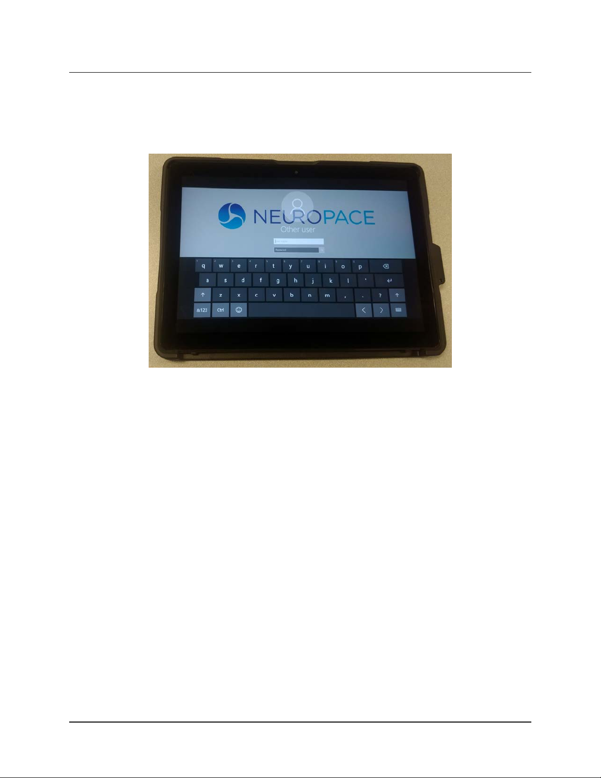
1. The tablet login screen appears first upon startup. Select a user. The screen prompts you for a
username and password and displays the keyboard.
®
TABLET
2. Enter your username and password (initi all y provid ed b y Neuro Pace) and select Enter. Login
completes if the password is correct and then the N
EUROPACE LOG IN screen appears, which lets
you login to the PDMS, as described next.
RNS® System Programming Manual
Page 19
Tablet Instructions 15
LOG IN TO THE PDMS
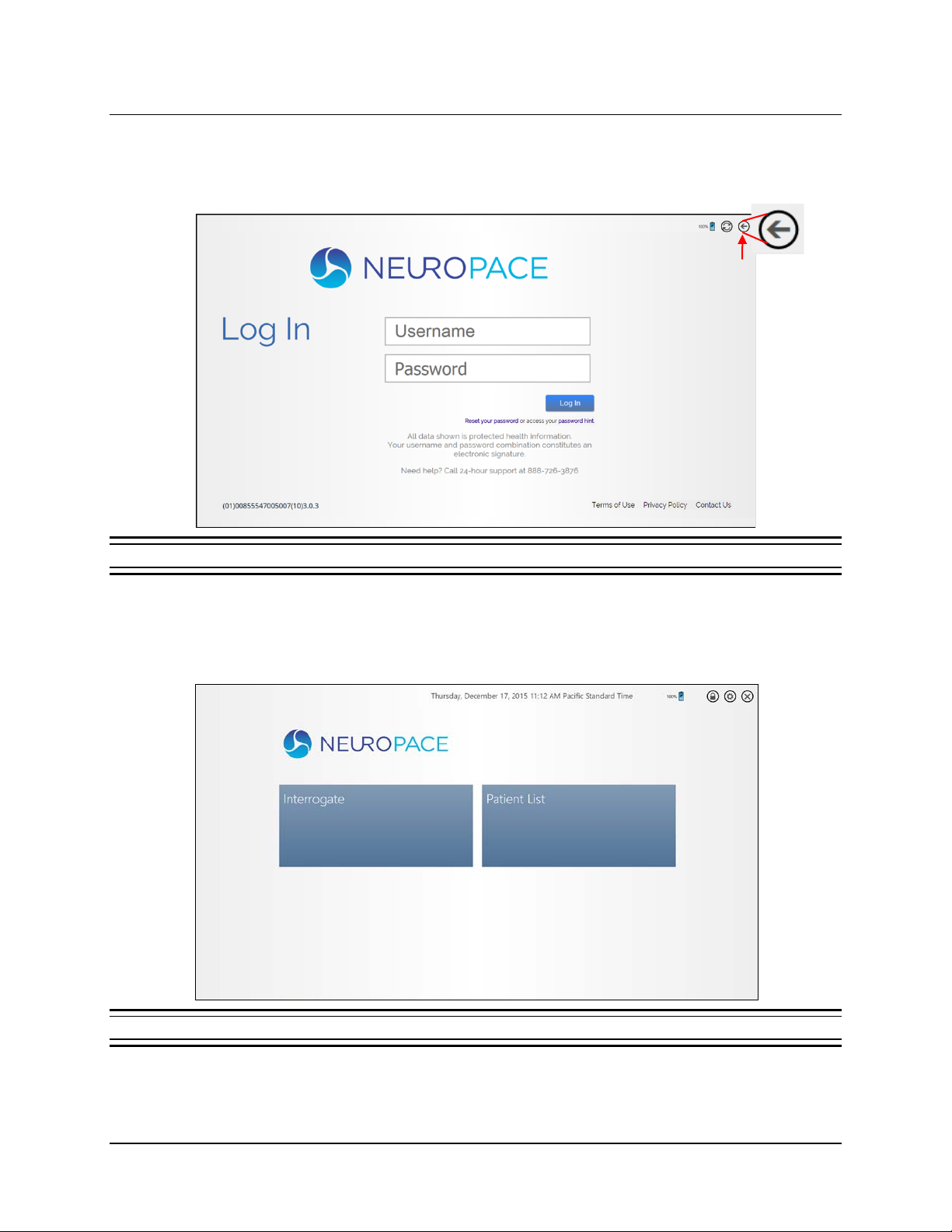
The NEUROPACE LOG IN screen appears after tablet login, and whenever you attempt to access functions
that require PDMS access, like the P
ATIENT LIST and ECOG LIBRARY.
If Internet not available, select Back
to go to Home screen without
logging into the PDMS.
Figure 2 NeuroPace Log In screen—for PDMS login
To skip PDMS login, select the BACK button in the upper right corner. The Start screen opens.
1. Select the fields to enter the username and pas sword and then select L
OG IN. Login completes
and the Start screen opens (Figure 3).
Figure 3 Start screen
RNS® System Programming Manual
Page 20
Tablet Instructions 16
INTERROGATE THE RNS
To interrogate the RNS® Neurostimulator means to identify it, perform routine tests and measurements,
and retrieve currently programmed settings and stored data from it. Follow these steps to interrogate:
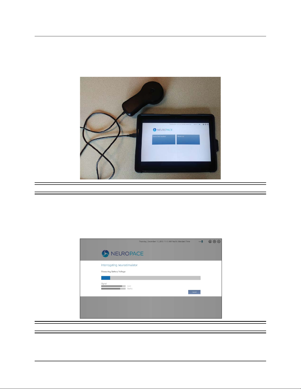
1. Connect the wand to the USB port on the tablet.
®
NEUROSTIMULATOR
Figure 4 Tablet with connected wand
2. Place the wand within appr ox imately 1 inch of the neurostimulator, concave side of wand
facing the neurostimulator. Then select I
Figure 3). You can also select the green I
(see Figure 6.) The wand must be held in place over the neurostimulator for interrogation to
succeed.
NTERROGATE from the Start screen (left tile—see
NTERROGATE tile at upper right in the HOME screen
Figure 5 Interrogating neurostimulator dialog—interrogation in progress
RNS® System Programming Manual
Page 21

Tablet Instructions 17
The INTERROGATING NEUROSTIMULATOR dialog shows progress and the HOME screen appears when
complete. It takes from 10 seconds up to 5 minutes, depending on the amount of data to be retrieved.
Interrogation does not significantly drain the neurostimulator battery
The dialog has bars that show the L
strength of the communication between the neurostimulator and the tablet. The Q
EVEL and QUALITY of the SIGNAL. The LEVEL measures the
UALITY measures
the absence of electronic interference in the environment. Poor signal level or quality can result in
Poor or No Communication Between the RNS® Neurostimul ator and the RNS® Tablet—see
page 96 for troubleshooting information.
DATA RETENTION AND ACCESS ON THE NEUROSTIMULATOR, PROGRAMMER AND PDMS
Programmed Settings
The neurostimulator retains its programmed settings until it is programmed again. These include the
recording montage, ECoG capture triggers and reservations, and the detection and stimulation
settings.
Note: ECoG capture triggers are inactive during programming. Programming clears activity
information (diagnostics) and EC oGs stored in the neurostimulator. If there is any new
information, be sure to interrogate the neurostimulator prior to programming.
Storage of ECoGs and Neurostimulator A ctivity (Diagnostics)
Between interrogations by the patient or a clinician, the neurostimulator stores ECoGs and
neurostimulator activity events up to its storage limit. (Neuros timulator activity events are also known
as diagnostics, which include, for example, detection and stimulation events and magnet swipes.)
Once the memory for ECoGs or diagnostics is full, the neurostimulator will store new data by
overwriting the oldest ECoG or diagnostics. Reserved ECoGs are overwritten only by newer ECoGs
of the same ECoG capture trigger type.
• The limit to the number of ECoGs stored on the neurostimulator depends on the capture
duration you select in the ECoG capture settings (see Set up ECoG Capture on page 37 for
details).
• You can make no adjustments that affect the number of neurostimulator activity events that
can be stored. However, the number of events that can be stored is large compared to the
number of ECoGs, because the data size of each event is relatively small.
At each interrogation with the remote monitor or programmer, the neurostimulator transfers all
stored ECoGs and diagnostics to the programmer or remote monitor, at which point the successfully
transferred data is cleared from the neurostimulator.
• If the programmer or remote monitor is not connected to the PDMS (via the Internet), the
transferred data remains on the programmer or remote monitor hard drive. You cannot view
ECoGs or diagnostics while stored on the programmer or remote monitor; it must be
transferred to the PDMS before you can view it.
• When the programmer is connected to the PDMS (via the Internet), the transferred data is
automatically uploaded to the PDMS and cleared from the programmer memory. When the
patient synchronizes using the remote monitor, data is transferred to the PDMS and cleared
from the remote monitor. Data is retained on the PDMS.
RNS® System Programming Manual
Page 22
Tablet Instructions 18
• L
date and time (24-
hour time)
• L
username
• Tablet battery status (%)
Toolbox button
Wireless Signal button
Note: If automatic upload to the PDMS does not complete successfully, data is not lost. Data is
cleared from the programmer or remote monitor only after a successful upload.
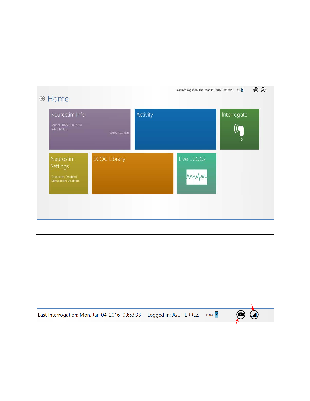
HOME SCREEN
The Tablet Home screen is the launch point for all programming activities.
Figure 6 Tablet Home screen
Note: When logged in to the PDMS, changes you make with the tablet are immediately saved to
the PDMS. If you lose connectivity, you will not lose information you already programmed into the
neurostimulator or saved to the PDMS, but you will lose information not already programmed into
the neurostimulator or saved to the PDMS.
The elements in the far upper right of the screen are present on all tablet screens.
AST INTERROGATION
OGGED IN
RNS® System Programming Manual
Page 23
Tablet Instructions 19
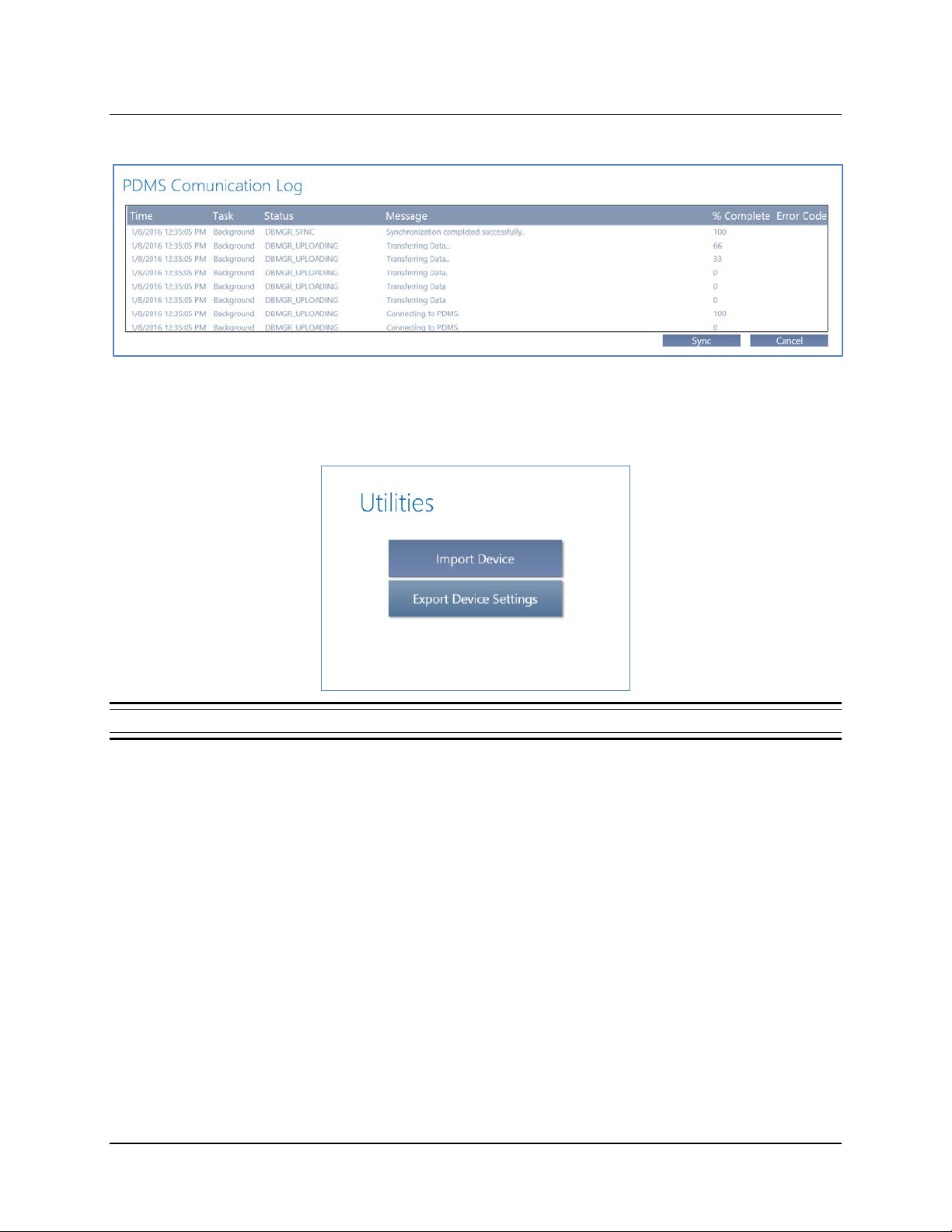
• WIRELESS SIGNAL button to access the PDMS COMMUNICATION LOG
• TOOLBOX button to access UTILITIES dialog to IMPORT DEVICE and EXPORT DEVICE SETTINGS.
These features are designed to support neurostimulator replacement. For instructions, see
Export and Import Device Settings for Neurostimulator Replacement on page 81.
Figure 7 Utilities dialog
RNS® System Programming Manual
Page 24
Tablet Instructions 20
NEUROSTIM INFO SCREEN
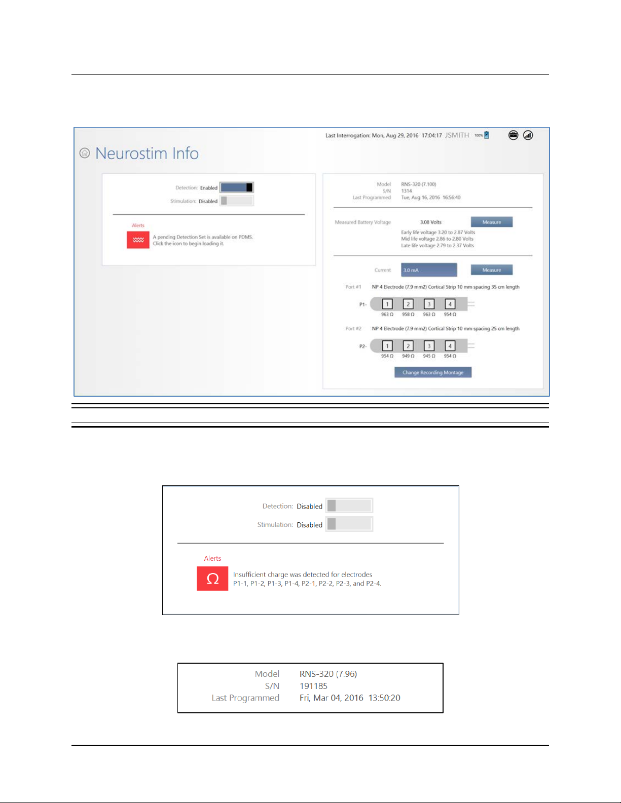
Select NEUROSTIM INFO from the HOME screen to open the NEUROSTIM INFO screen.
Figure 8 Neurostim Info screen
The NEUROSTIM INFO screen provides information about the neurostimulator, including:
• At upper left, whether D
ETECTION and STIMULATION are ENABLED or DISABLED and Alerts, if any
• At upper right, MODEL, serial number (S/N) and LAST PROGRAMMED date and time (24-hour time)
RNS® System Programming Manual
Page 25
Tablet Instructions 21
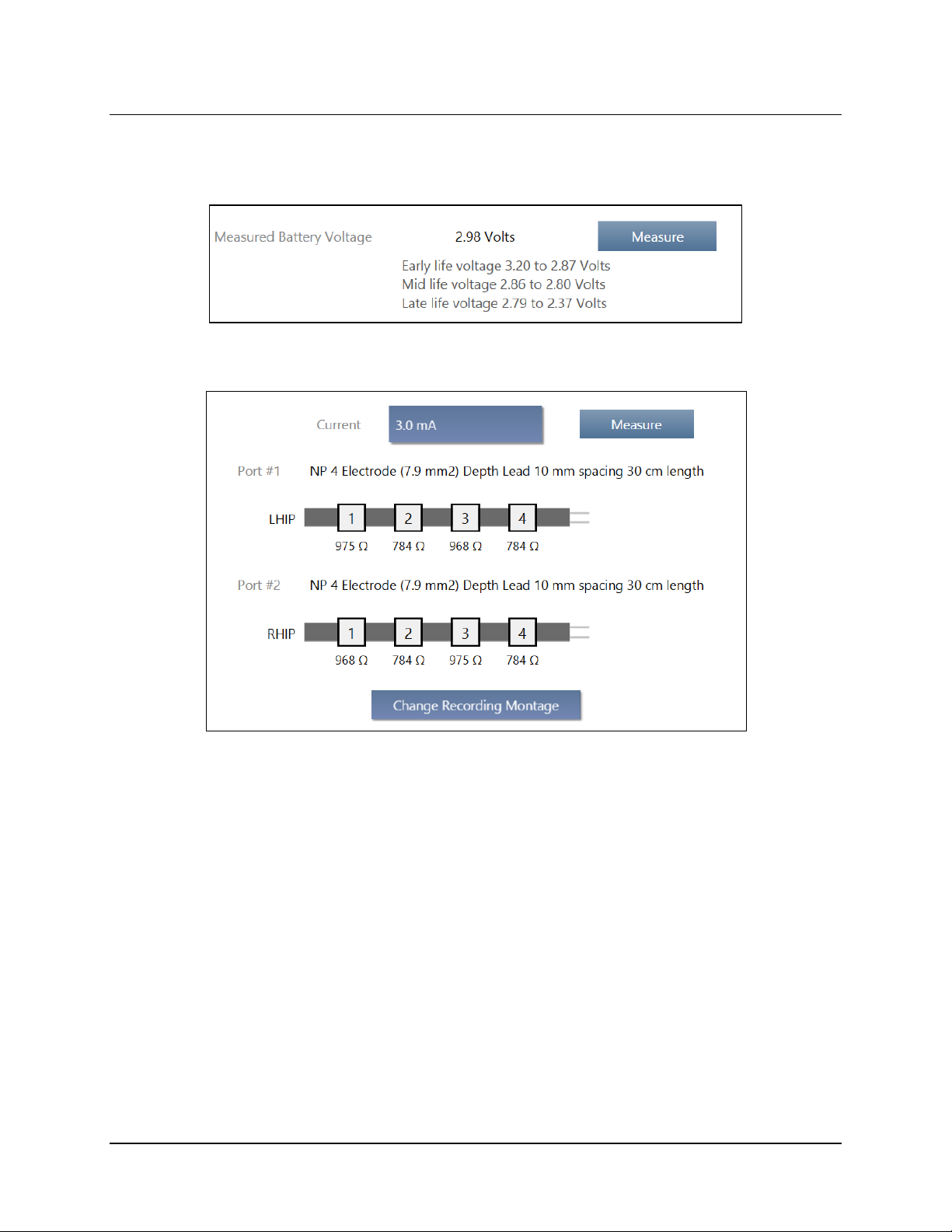
• At middle right, MEASURED BATTERY VOLTAGE with MEASURE button. The early, mid and late life
voltage ranges are displayed to give context to the measured voltage. See Significance of
Battery Voltage on page 23.
• At lower right, measured impedance for electrodes on the PORT #1 and PORT #2 leads
• Buttons to M
EASURE impedance manually
using the amount of C
is measured routinely during
URRENT selected. (It
• A button to C
HANGE RECORDING MONTAGE,
as explained under Creating the Montage
on page 34
interrogation.)
RNS® System Programming Manual
Page 26
Tablet Instructions 22
Electrode Impedance and Battery Voltage
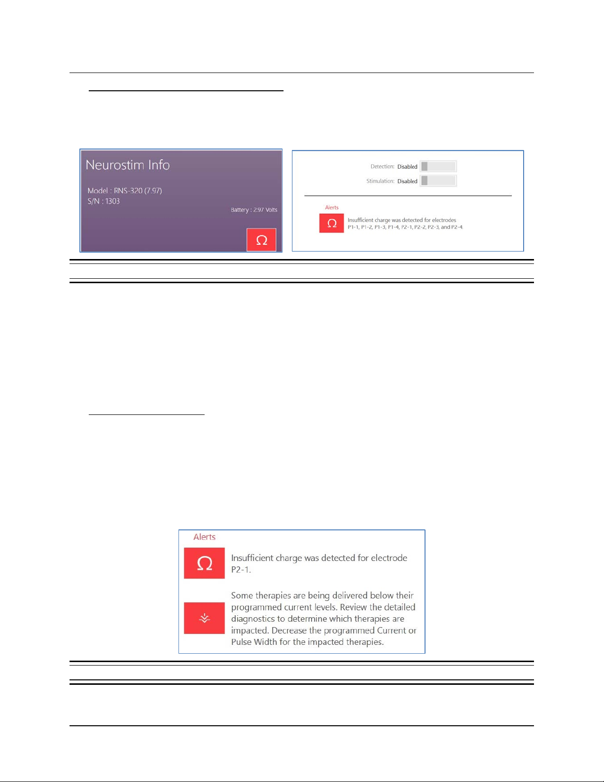
Interrogation includes measuring electrode impedance and battery voltage, and these measurements
are reported on the N
impedance measurement detects insufficient charge for one or more electrodes.
Figure 9 Insufficient charge alert shown on the NEUROSTIM INFO tile and screen
To measure these items again, place the wand within approxim ately 1 inch of the neurostimulator and
select the applicable M
get there). For impedance measurements, use the C
during measurement.
EUROSTIM INFO screen. The NEUROSTIM INFO tile and screen show an alert if the
EASURE button on that screen (select NEUROSTIM INFO from the HOME screen to
URRENT field to adjust the current delivered
Note: The system cannot measure impedance during a detected episode or during therapy
delivery. To measure impedance, either wait for the episode or therapy to complete, or disable
detection and therapy.
Significance of Impedance
Impedance measurements are useful for verifying the integrity of a particular electrode. Each
impedance measurement delivers a single pulse of current between an electrode and the
neurostimulator canister (can) to measure the voltage that results as the current flows. Impedance
measurements are reported in Ohms (voltage divided by current).
Impedance measurements greater than 3500 Ohms or less than 250 Ohms are considered abnormal.
If impedance measurements are abnormally high, there may be insufficient charge to deliver therapy.
When this is the case, alerts may appear on the Neurostim Info screen as shown below in Figure 10.
Figure 10 Alerts when there is insufficient charge to deliver therapies
RNS® System Programming Manual
Page 27
Tablet Instructions 23
For troubleshooting information, refer to Abnormal Lead Impedance (greater than 3500 Ohms or
less than 250 Ohms) on page 92; and Insufficient Charge on page 95.
Significance of Battery Voltage
Normal RNS® Neurostimulator battery voltage measurements are between 2.38 and 3.20 Volts.
When the battery voltage measurement drops to 2.37 Volts or less, neurostimulator replacement is
recommended, and the tablet notifies you on screen by showing the elective replacement indicator
(ERI).
ACTIVITY SCREEN
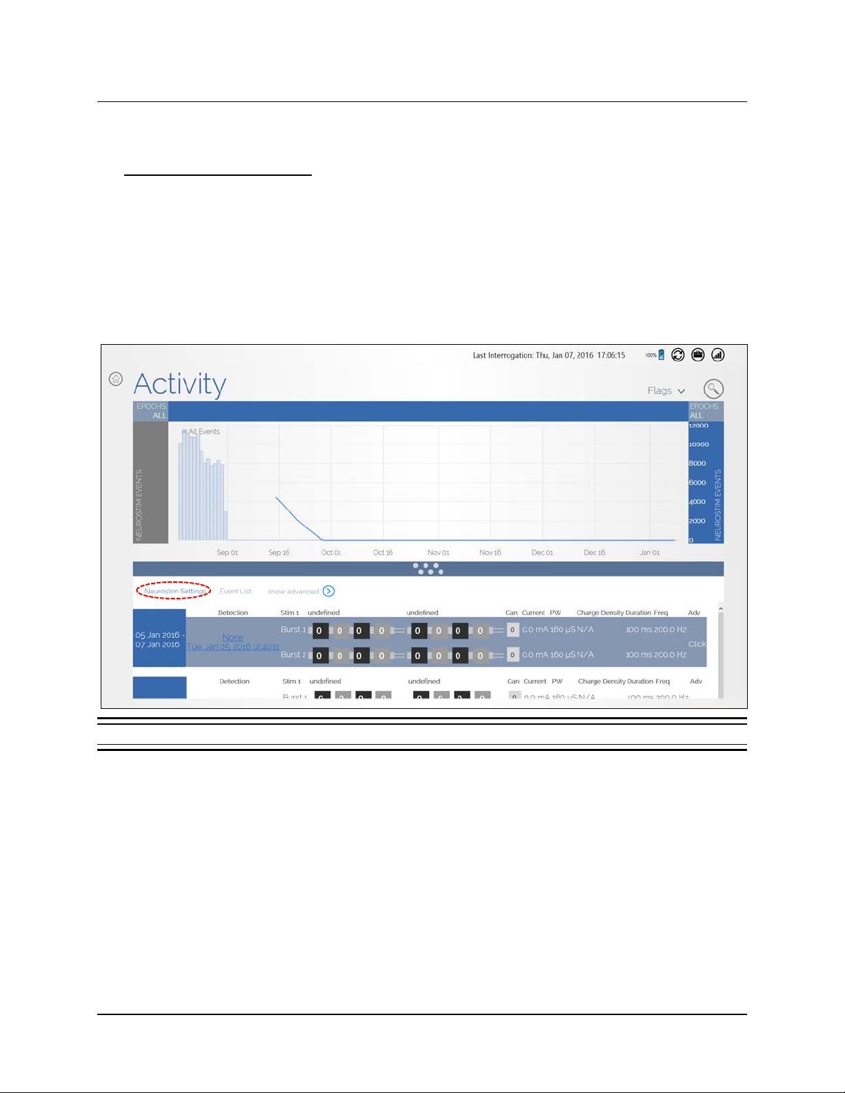
Select ACTIVITY from the HOME screen to open the ACTIVITY screen.
Figure 11 Activity screen
Note: You must be logged in to the PDMS to access the ACTIVITY screen. If you are not, the
N
EUROPACE LOG IN screen opens when you select ACTIVITY, prompting you to log in. (See Log In
to the PDMS on page 15.) If you are not connected to the Internet, see Connect to the Internet
for PDMS Access on page 10.
The upper part of the A
CTIVITY screen is a histogram that shows the number of detection and stimulation
events over time. Swipe left or right over the dates to view earlier or later activity. The lower part of the
screen shows (by default) a list of the N
EUROSTIM SETTINGS—detection and stimulation settings—used
over time, one row for each period of time between programming changes, which is called a programming
epoch. More view options ar e descr ibe d below .
RNS® System Programming Manual
Page 28
Tablet Instructions 24
Select event types
to layer on graph
Activity Histogram Viewing Options
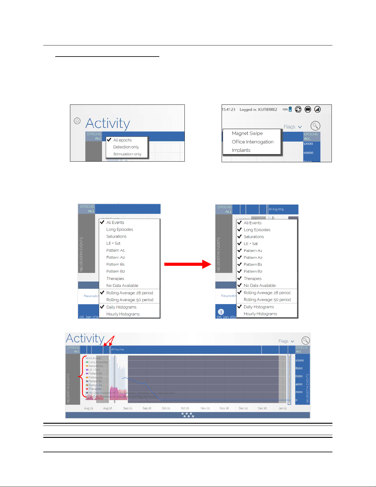
The interface provides many options for viewing activity.
• Select E
events from A
or S
TIMULATION ONLY.
POCHS at upper left or right to see
LL EPOCHS, DETECTION ONLY
• Select F
flagged with M
INTERROGATION or IMPLANTS.
LAGS at upper right to see events
AGNET SWIPE, OFFICE
• Select NEUROSTIM EVENTS on the left or right sides of the histogram to select items for layering on
the graph; you can select multiple items concurrently, up to all items in the upper part of the list. A
color legend appears on the left to help you recog ni ze what is on the histo gram.
Vertical lines on top indicate
date ranges of each epoch
Legend
Figure 12 Activity histogram with all events showing and supporting legend on left
RNS® System Programming Manual
Page 29
Tablet Instructions 25
View Neurostim Settings
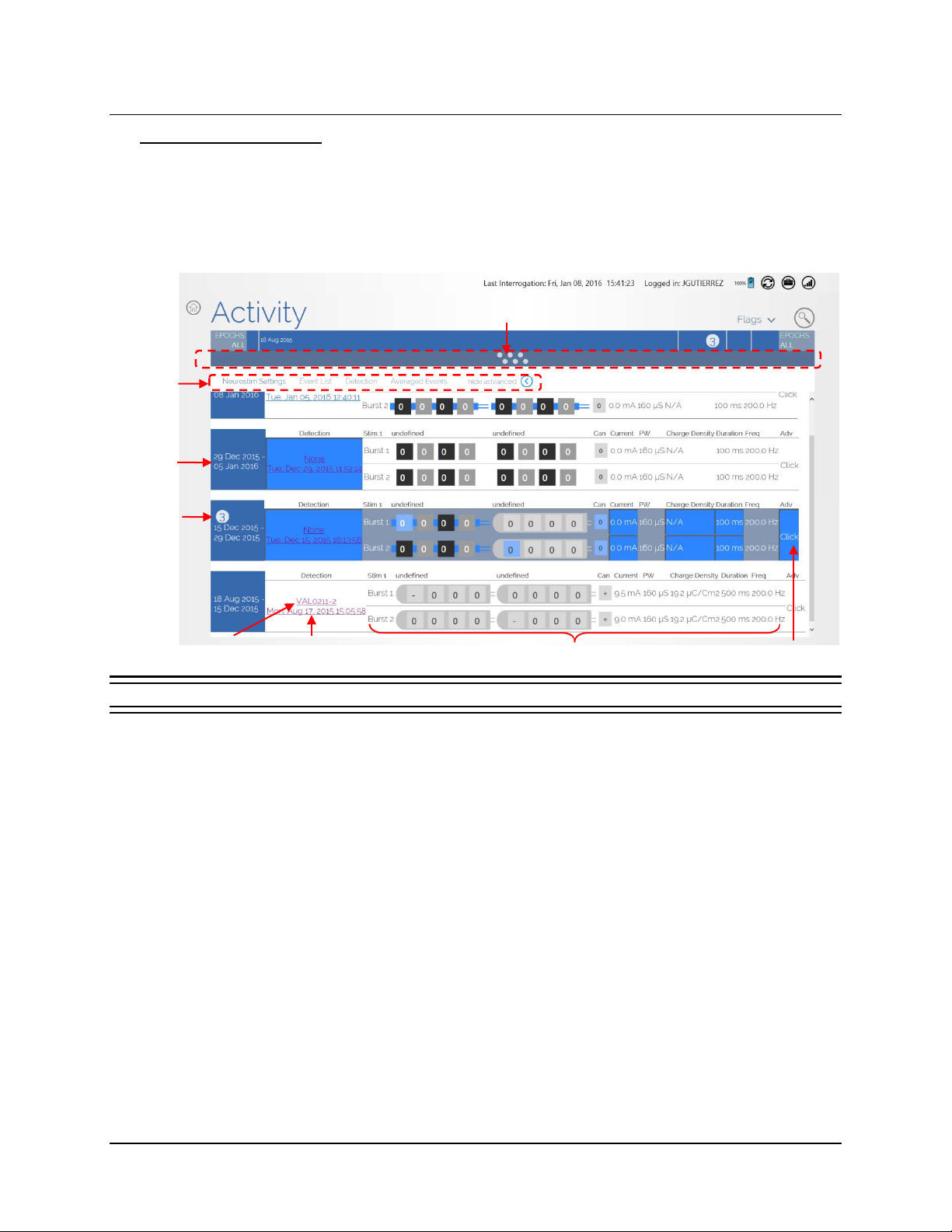
The lower part of the ACTIVITY screen details the history of detection and stimulation settings used—
collectively called N
epoch), which are in rows from most recent on top to oldest on the bottom. Drag up the gray
separator bar to view more of these settings, which will cover the upper histogram portion. Swipe up
on the setting rows to v ie w m or e rows, if they are present.
View options
Date range of
programming
epoch
Select to see
row number
EUROSTIM SETTING S—between each iteration of programming (each programming
Drag up the separator bar to cover histogram
and view more N
EUROSTIM SETTINGS.
Detection set name
—select for details
Figure 13 Activity screen—view detection and stimulation settings used between programming sessions
Date settings
created
Stimulation therapy
settings used
Select CLICK to see
Advanced settings used
At the left end of each row is a blue tile showing the date range when those NEUROSTIM SETTINGS
were used. Vertical lines above the histogram correspond to these dates (see Figure 12 above).
When you select a blue tile, its row number appears on the tile (see Figure 13 above, row numbers
increase as you go down).
RNS® System Programming Manual
Page 30
Tablet Instructions 26
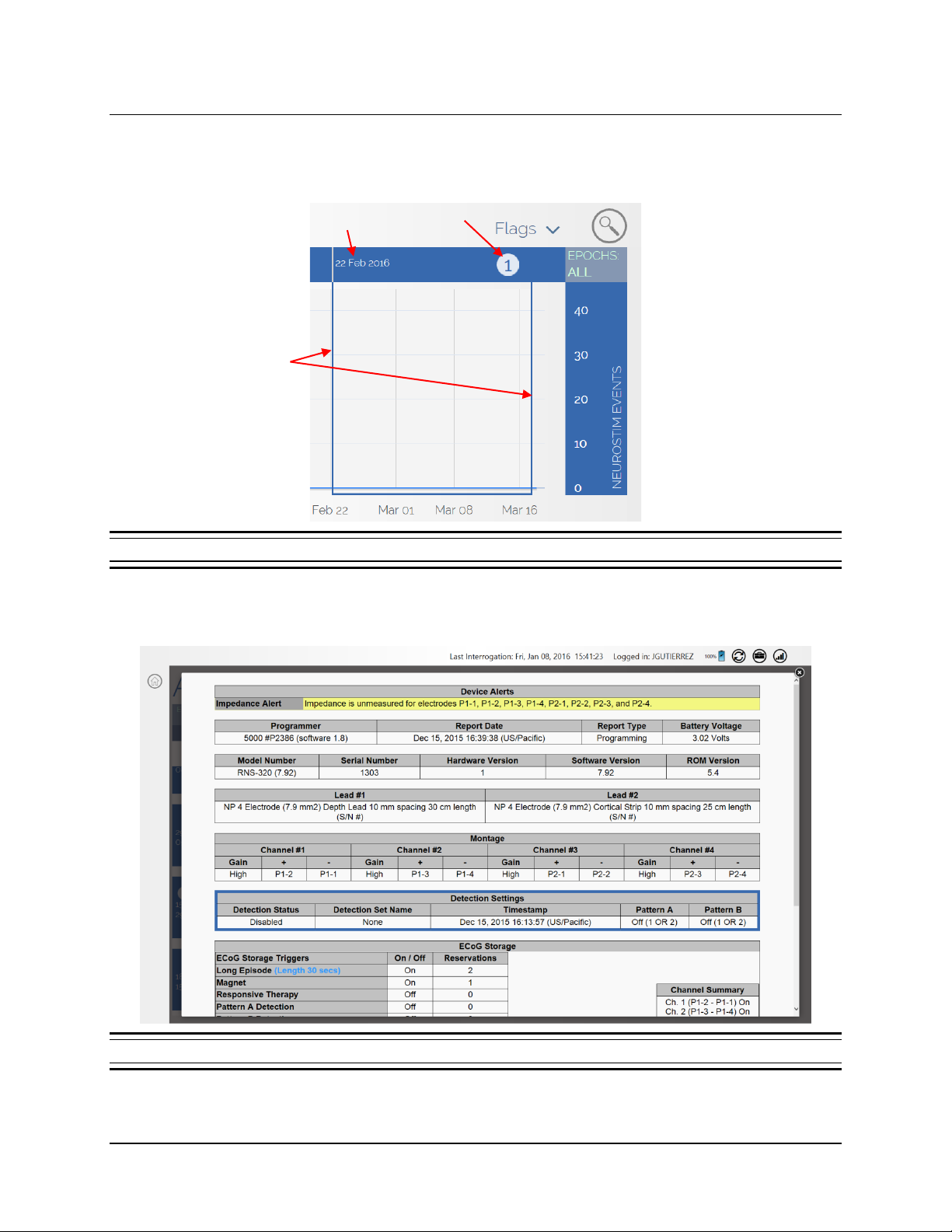
Also the corresponding time period is bracketed in the histogram graph, and the row number and start
date appear over the br ack eted time period, if there is enough room on screen (see F
helps to relate the programming changes to the device activity.
IGURE 14). This
Programming Start Date
Brackets of
programming epoch
Row number
Figure 14 Activity histogram excerpt showing programming epoch 1 bracketed
Next to the blue tiles, the second column in Figure 13 shows the name of the DETECTION set. Select
the name to view its details in the screen that opens (Figure 15). Touch (X) at upper right to close.
Figure 15 Detection set details
RNS® System Programming Manual
Page 31
Tablet Instructions 27
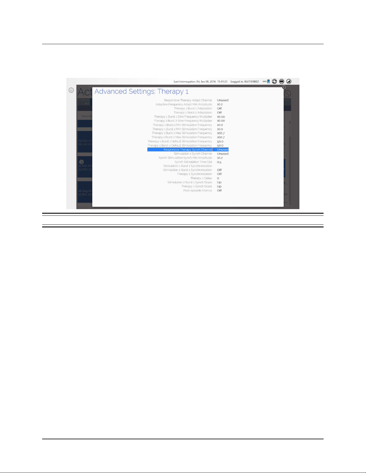
At the right end of each row in Figure 13 is the ADV (Advanced) column. Touch CLICK below ADV to
view any advanced settings used in the screen that opens (Figure 16). Touch (X) at upper right to
close.
Figure 16 Advanced stimulation therapy settings used
RNS® System Programming Manual
Page 32
Tablet Instructions 28
View Event List
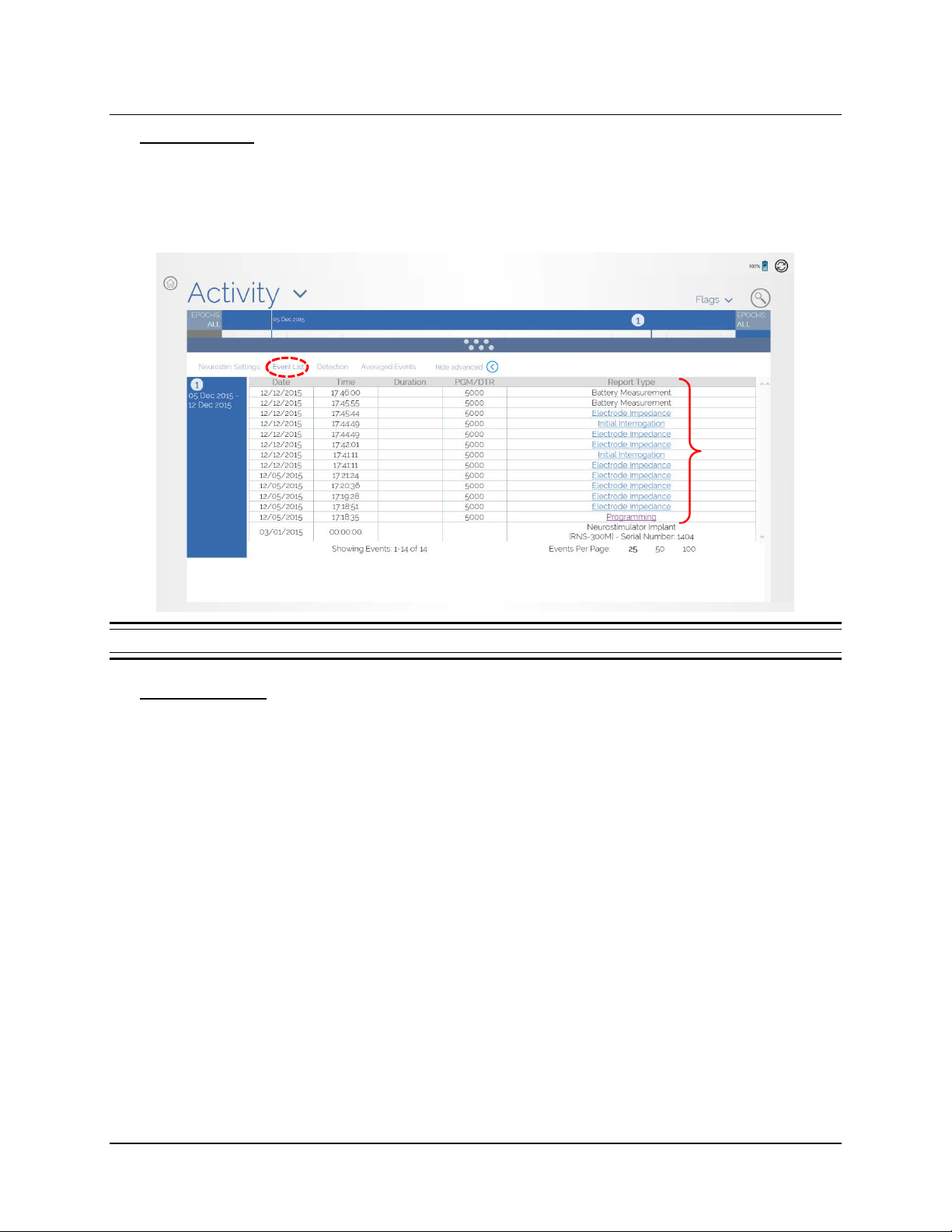
Select EVENT LIST next to NEUROSTIM SETTINGS above the left end of the row (Figure 17) to see a
complete list of events for all rows. From there, select links under R
on each event. Swipe up or down in the blue column on the left to scroll between programming
epochs. Swipe up or down within the event lis t it s elf to s c r oll the list of events.
EPORT TYPES for detailed reports
Select to see
event report
Figure 17 Event List selected—lists all events in a Neurostim Settings period, with links to reports
Types of Reports
There are six types of patient reports:
• Interrogation (Initial or Subsequent within the tablet session)
Interrogation time/dat e
• Programmed Neurostimulator settings
• Event counters (# of detections, stimulations, etc.)
• Event date/time and details
• Programming
• Programming date/time
• Programmed Neurostimulator settings
• Electrode Impedance
• Impedance measurement date/time
• Impedance measurement of each electrode (in ohms)
• Battery Measurement
• Battery measurement date/time
• Battery measurement value (in volts)
RNS® System Programming Manual
Page 33

Tablet Instructions 29
• Therapy Testing (sho ws th erap y testing va lu es )
• ECoG
• ECoG trigger time/date
• ECoG record
• ECoG trigger reason
• ECoG markers (detections, stimulations, etc.)
Advanced Views
DETECTION, AVERAGED EVENTS and PROGRAMMING EPOCHS are the advanced views. DETECTION
shows a graph of detection occurrence percentage for each programmed detection pattern since the
last change in detection settings. A
normalized average number of detected episodes per hour for the last 12 weeks. P
VERAGED EVENTS shows a week by hour histogram of the
ROGRAMMING
EPOCHS shows the history of recent programming epochs, summarizes the settings and activity of
each epoch, and highlights the changes in settings and activity from one epoch to the next.
ECOG LIBRARY SCREEN
It is recommended to review ECoGs stored in the library to assess how early and how often detections
occur and the electrographic response to stimulation therapies delivered. Select EC
H
OME screen to open the ECOG LIBRARY screen, which displays thumbnails of all ECoGs stored for the
current patient.
OG LIBRARY from the
Note: You must be logged in to the PDMS to access the ECoG library. If you are not, the
N
EUROPACE LOG IN screen opens when you select ECOG LIBRARY, prompting you to log in. (See
Log In to the PDMS on page 15.) If you are not connected to the Internet, see Connect to the
Internet for PDMS Access on page 10.
RNS® System Programming Manual
Page 34
Tablet Instructions 30
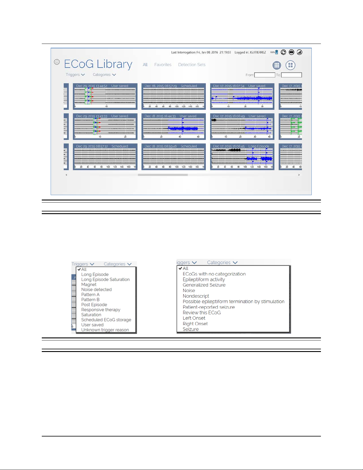
Triggers filters
Categories filters
Figure 18 ECoG Library screen
Each ECoG is identified by date and time captured and by capture trigger. Newest ECoGs are on the left,
older ones toward the right. Swipe left or right to view all ECoGs. You can filter which ECoGs are
displayed using T
RIGGERS and CATEGORIES at upper left (Figure 19). Use the FROM and TO fields at
upper right to view ECoGs by date range.
Figure 19 Filter stored ECoGs by triggers and categories
At top center (see Figure 18), you can select ALL, FAVORITES or DETECTION SETS to display ECoGs by
those classifications.
RNS® System Programming Manual
Page 35
Tablet Instructions 31
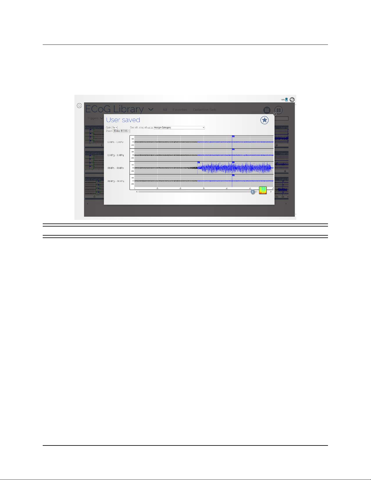
Select a thumbnail to open it in a larger size, as shown below. ECoGs highlight detection and stimulation
events. Detected activity appears in blue. Undetected activity appears in black. Colored flags mark
specific points of detection or stimulation. You can Z
A
SSIGN CATEGORY field to assign the ECoG to a category. Select the STAR button at upper right to specify
this ECoG as a favorite, for fast access later using the F
OOM in on the ECoG and increase the GAIN. Use the
AVORITES filter on the ECOG LIBRARY screen.
Figure 20 Viewing a User saved ECoG
Captured ECoGs reside in the RNS® Neurostimulator memory until they are transferred to the
programmer at the next inter r ogation with the wand, and are then cleared from memory. If
neurostimulator memory capacity is reached, captured ECoGs are overwritten by subsequent ECoGs.
The number of ECoGs that can be stored depends on the duration of each ECoG, which you can specify
in the C
APTURE WINDOW field in the DURATION area on the far upper right side of the ECOG CAPTURE
screen. See Selecting ECoG Capture Settings on page 38 for details.
LIVE ECOGS SCREEN
Note: You can access the LIVE ECOGS screen only after interrogation of the neurostimulator, and
the wand must be held within approximately 1 inch of the neurostimulator to acquire live ECoGs.
RNS® System Programming Manual
Page 36
Tablet Instructions 32
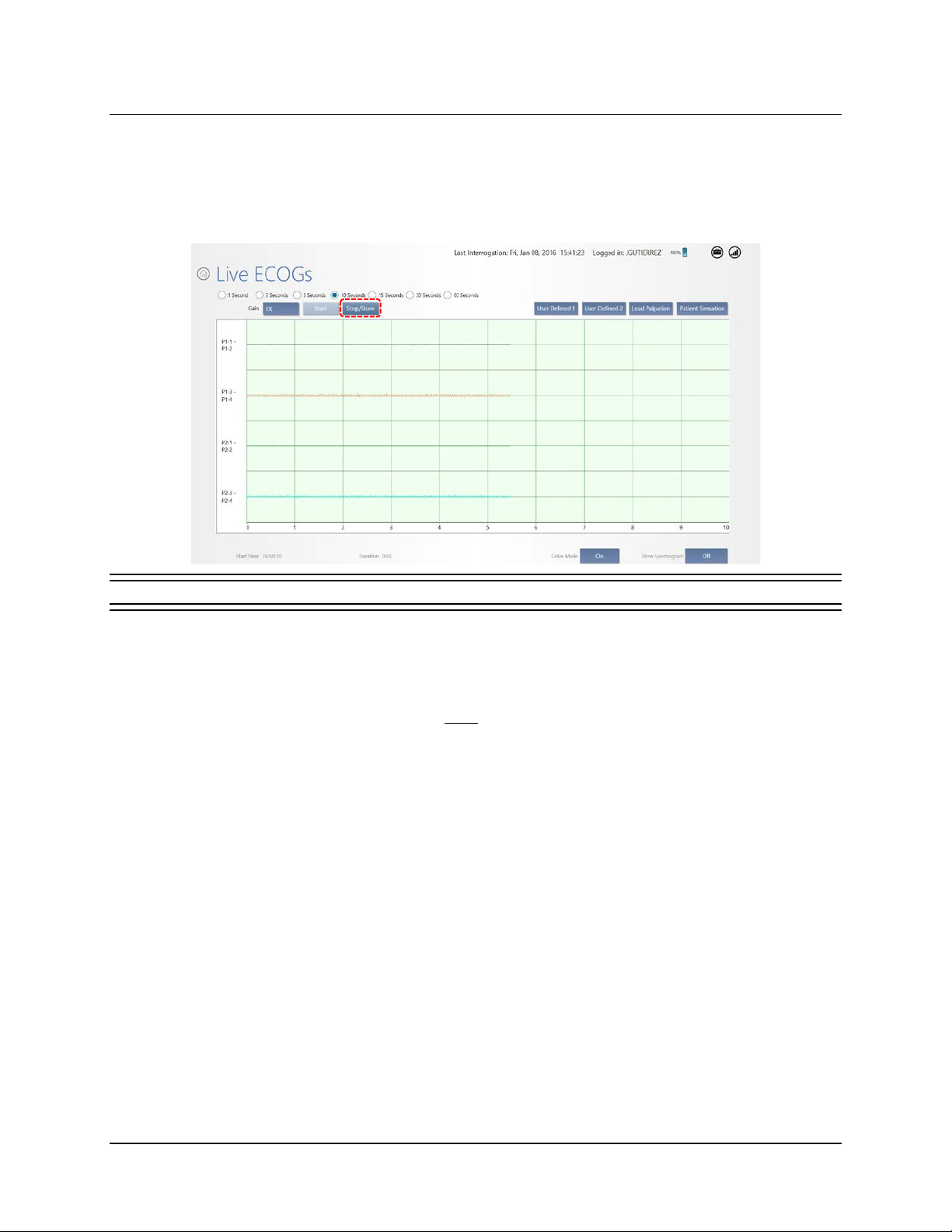
After interrogation, keep the wand in place and select LIVE ECOGS from the HOME screen to open the
L
IVE ECOGS screen. An ECoG is live when you open it. Buttons provide various options for viewing the
live ECoG. Select S
you stop and store it until you start another live ECoG. Captured live ECoGs are stored in the EC
LIBRARY and classified as User saved.
TOP/STORE to save the ECoG in the patient’s ECoG library. It remains on screen after
OG
Figure 21 Live ECoGs screen
Live ECoG capture can be useful for immediate or later analysis of patient ECoGs, for adjusting amplifier
gain settings, and for simulated detection as part of Configure Pattern Detection: Define and Modify
Detection Settings (see page 44).
Important Note: The recording montage must be programmed before live ECoGs can be viewed. See Create the Recording Montage on page 32.
Note: The maximum length for a live ECoG is four minutes. If the live ECoG is allowed to scroll
for more than four minutes, only the last four minutes are stored.
Note: Live ECoGs are stored on the tablet, not in the neurostimulator memory, and are uploaded
to the PDMS if and when the tablet is logged into the PDMS.
Caution: Telemetry Artifact
Telemetry may produce an electrographic artifact. If responsive therapy is enabled
with a sensitive detection set, detection of the electrographic artifact may occur,
resulting in therapy delivery. The physician should be aware of possible sensing
artifacts when assessing the ECoG recordings.
CREATE THE RECORDING MONTAGE
The RNS® Neurostimulator can sense brain activity (ECoGs) from up to four amplifier channels. The
programmed configuration of leads and electrodes you assign to each channel constitute the recording
montage. You create the montage using the tablet. There can be only one current montage and
RNS® System Programming Manual
Page 37
Tablet Instructions 33
corresponding detection settings. When the montage is altered, the detection settings created
with the previous montage are discarded and the detection settings must be reprogrammed.
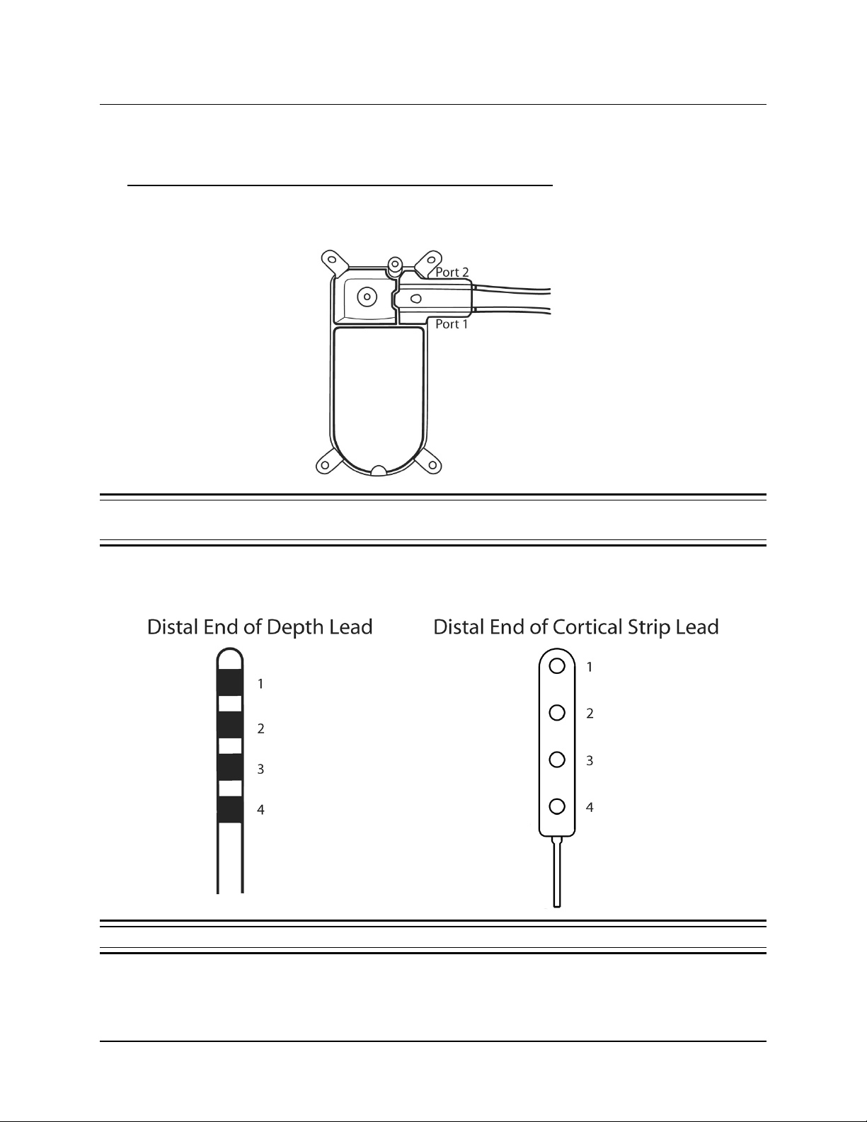
Identifying Ports, Leads and Electrodes on the Neurostimulator
The figure below identifies neurostimulator PORT #1 and PORT #2 with their leads extending out of the
ports.
Figure 22 RNS® Neurostimulator port #1 and #2 locations. Port #1 is closer to the center of the neurostimulator and port #2
is closer to the edge.
For both depth leads and cortical strip leads, the electrodes are numbered 1 through 4 starting from
the distal end of the lead.
Figure 23 For both lead types, electrodes are numbered 1 through 4. Electrode 1 is most distal.
RNS® System Programming Manual
Page 38
Tablet Instructions 34
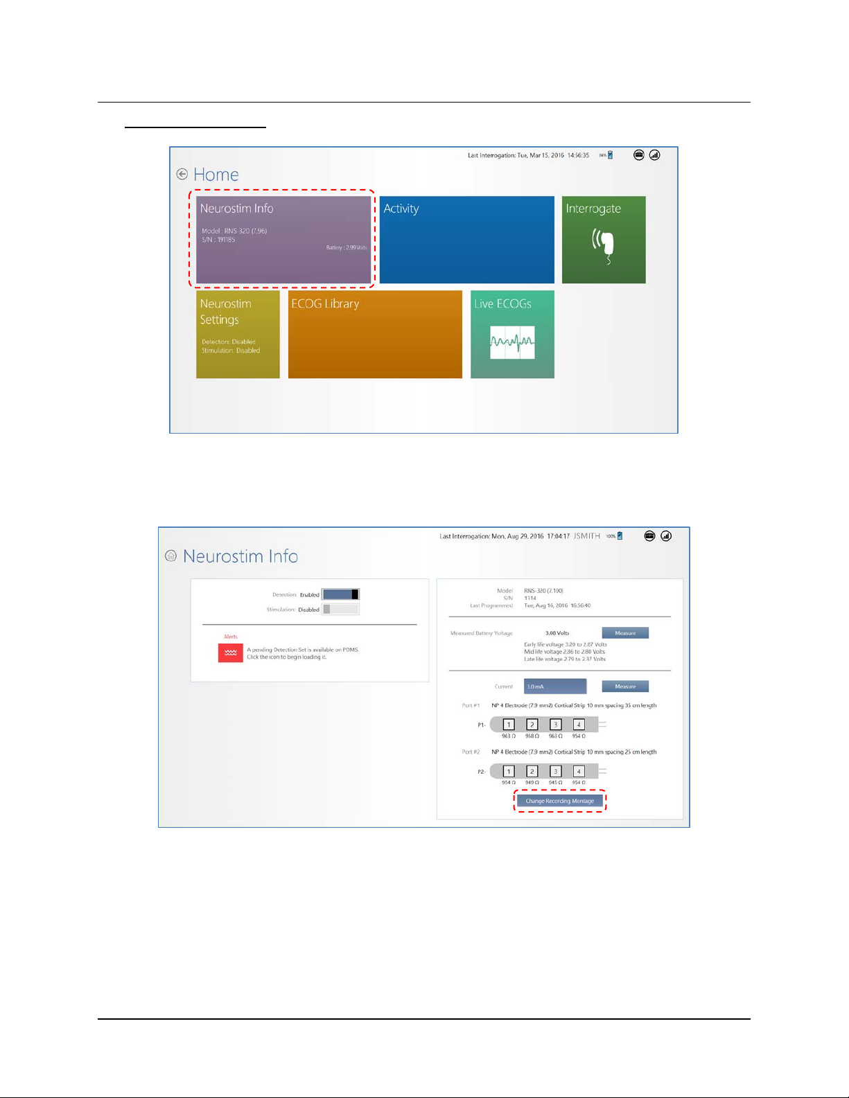
Creating the Montage
1. From the H
Note: For all settings, changed settings are indicated by blue buttons. Gray buttons indicate
settings have not changed.
OME screen, select NEUROSTIM INFO. The NEUROSTIM INFO screen opens.
2. On the N
R
ECORDING MONTAGE screen opens.
EUROSTIM INFO screen, select CHANGE RECORDING MONTAGE at lower right. The
RNS® System Programming Manual
Page 39
Tablet Instructions 35
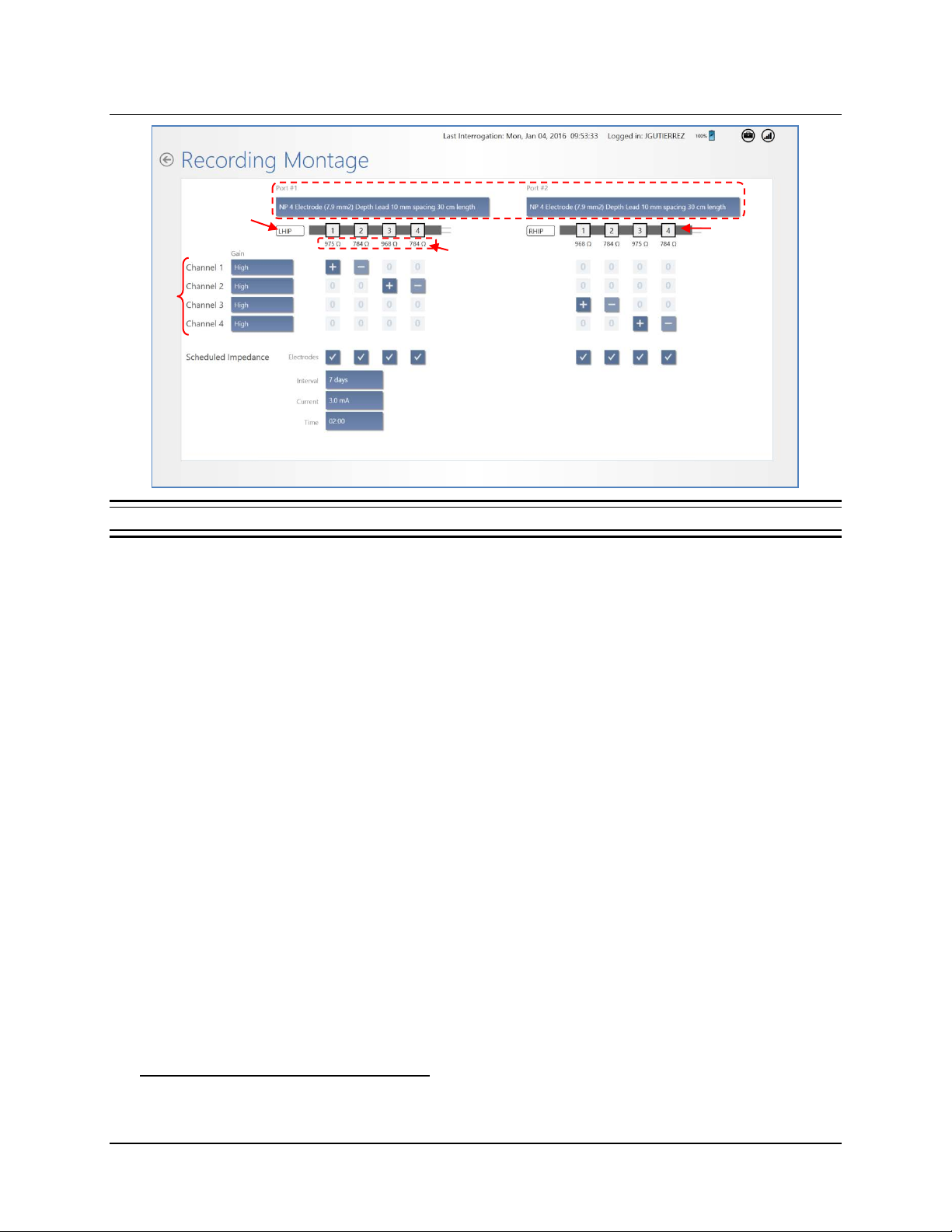
Select type of lead for Port #1 and Port #2
Lead label is
editable
Measured
Impedances
Channel
Rows
Figure 24 Recording Montage screen
Electrodes 1 - 4
for lead on Port #2
3. At Neurostimulator Implant and When Changing Leads – Select Lead Type: Upon first
use of leads, you must select the lead type for P
field that says N
ONE, just below the PORT #1 or PORT #2 names at the top, and select the type
ORT #1 and/or PORT #2. To do this, select the
of lead installed in each port. When lead types are already selected for the ports, proceed to
the next step.
4. Assign Channels: Use the channel rows and electrode columns to assign two electrodes to
each C
HANNEL (1 through 4). To do this, select the small, square field where the channel and
electrode intersect and then select a positive [+] non-inverting input, a negative [–] inverting
input, or zero [0]. Detection occurs across the selected electrodes for each channel.
Each electrode can be assigned to one or two channels. The tablet requires you to use a
positive [+] input for electrodes assigned to two channels.
Note: The tablet does not permit use of a negative [–] input for electrodes assigned to two
channels because it may result in ECoG artifacts.
5. Set Gain: Next to the channel name on the left, select the G
select H
IGH, MEDIUM-HIGH, MEDIUM-LOW, or LOW. The default is HIGH and it is usually not
AIN field for each channel to
changed. After programming, you can assess ECoG signal amplification by viewing the live
ECoGs.
6. Scheduled Impedance Settings: These settings are at lower left. By default, the tablet
schedules an impedance test on all electrodes every 7 days with 3.0 mA current at 2:00
Select the fields next to I
NTERVAL, CURRENT and TIME to choose different settings. Normally
AM.
there is no need to use other than the default settings.
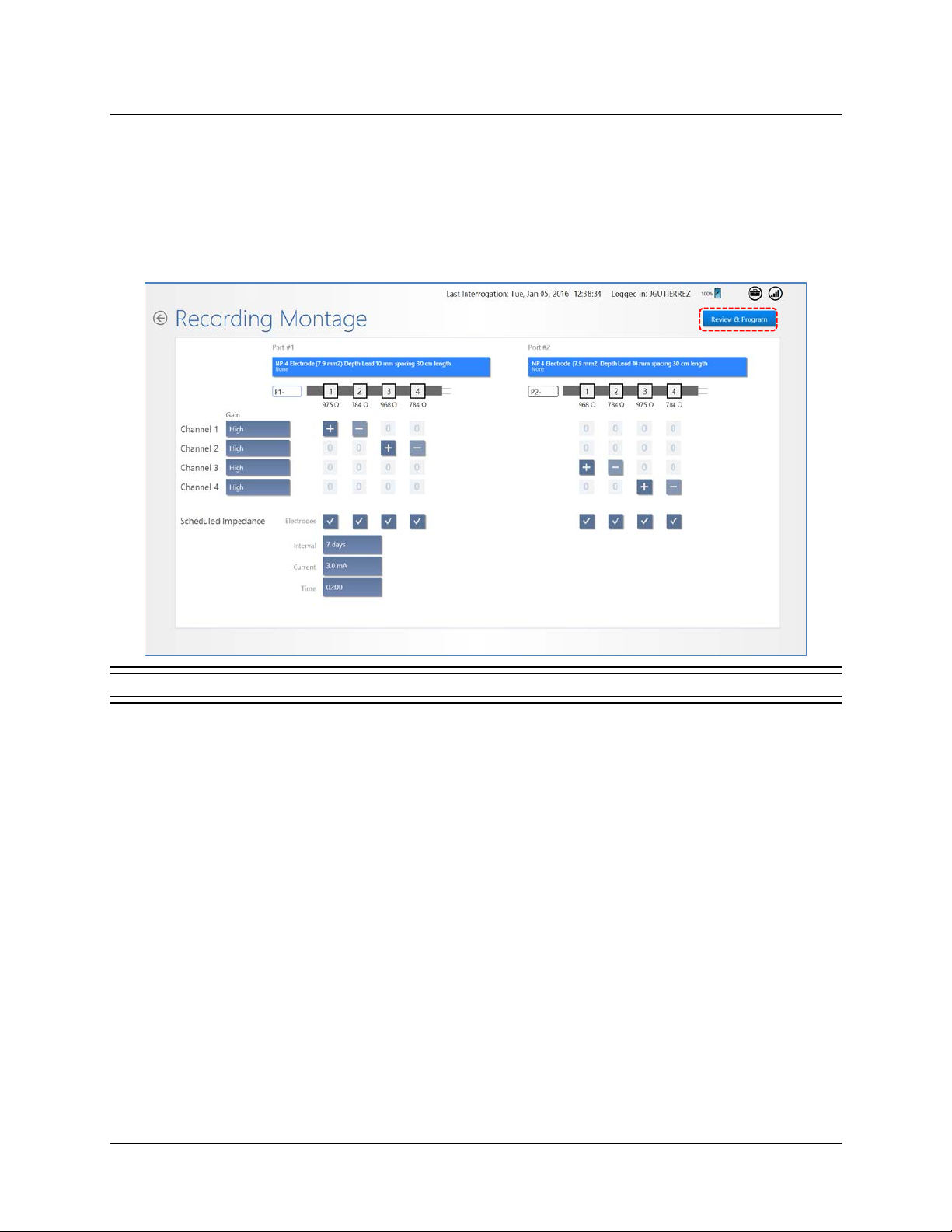
Recommended Initial Montage Settings
• Channel 1 = Lead 1: Electrode 1 [+], Electrode 2 [–]
RNS® System Programming Manual
Page 40
Tablet Instructions 36
• Channel 2 = Lead 1: Electrode 3 [+], Electrode 4 [–]
• Channel 3 = Lead 2: Electrode 1 [+], Electrode 2 [–]
• Channel 4 = Lead 2: Electrode 3 [+], Electrode 4 [–]
AIN set to HIGH for all channels (default)
• G
CHEDULED IMPEDANCE settings = Interval: 7 days, Current: 3.0 mA, Time: 2:00 AM (defaults)
• S
Figure 25 Recommended initial monta g e settings
RNS® System Programming Manual
Page 41
Tablet Instructions 37
Program the Neurostimulator with the New Settings
The new settings are not sent to the neurostimulator until you complete this step.
Note: ECoG capture triggers are inactive during programming. Programming clears activity
information and ECoGs stored in the neurostimulator. If there is any new information, be sure
to interrogate the neurostimulator prior to programming.
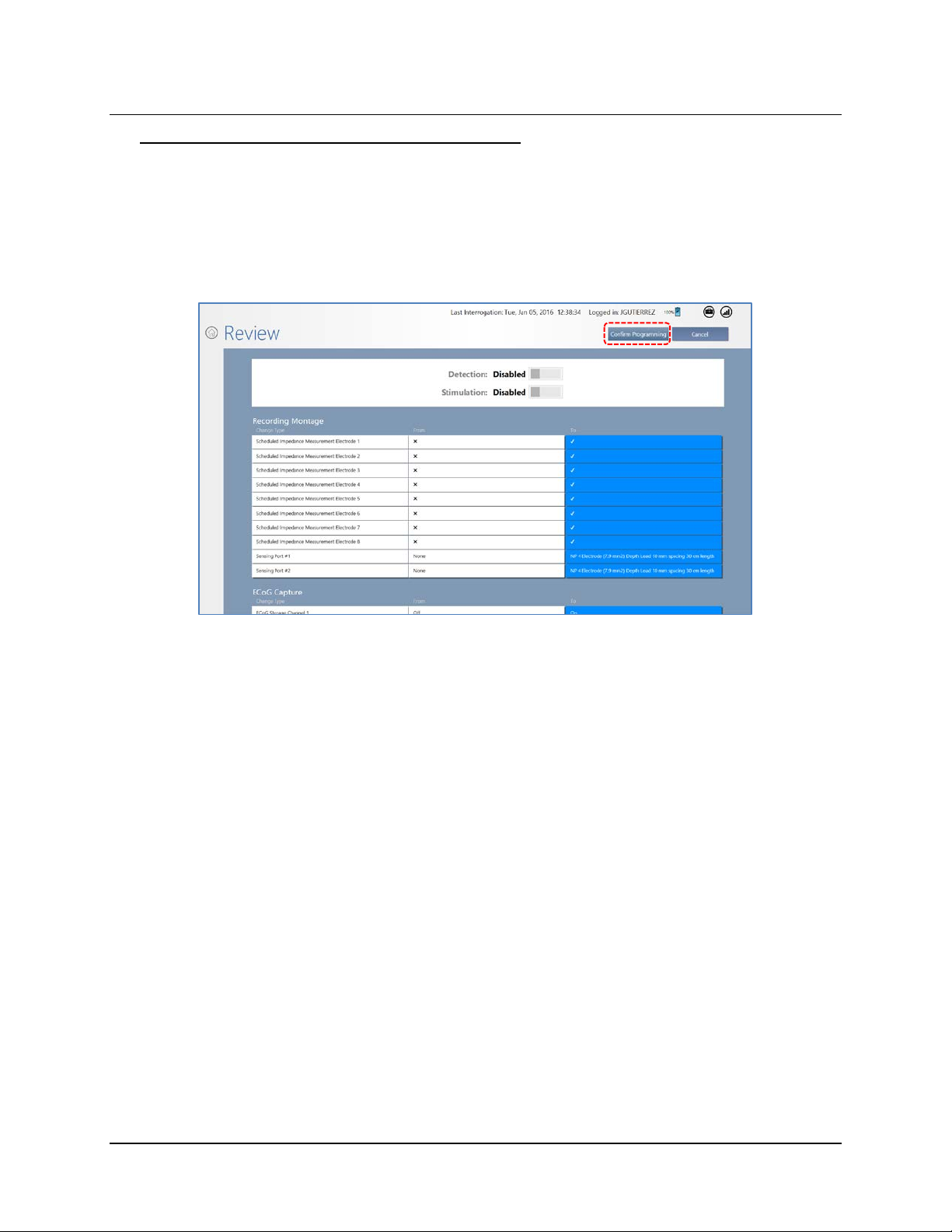
7. Select R
8. On the R
EVIEW & PROGRAM at upper right (Figure 25).
EVIEW screen, if you are satisfied with the new or changed settings, place the wand
within approximatel y 1 inch of the neurostimulator and select C
satisfied, select C
ROGRAMMING NEUROSTIMULATOR dialog shows programming progress until complete.
The P
ANCEL to return to the previous screen.
ONFIRM PROGRAMMING. If not
RNS® System Programming Manual
Page 42
Tablet Instructions 38
SET UP ECOG CAPTURE
Electrocorticograms (ECoGs) can be stored by the RNS® Neurostimulator when an ECoG capture trigger
occurs. The maximum number of ECoGs that can be stored is affected by the number of channel(s)
selected ON for storage, and the pre-trigger and post-trigger durations. The oldest stored ECoGs are
continually replaced by the newly stored ECoGs, except as noted below.
The number of ECoGs stored for a particular ECoG capture trigger can be reserved. Reserved ECoGs
are only overwritten by newer ECoGs of the same ECoG capture trigger type.
ECoG capture may also be scheduled at four different times on a 24-hour clock.
Selecting ECoG Capture Settings
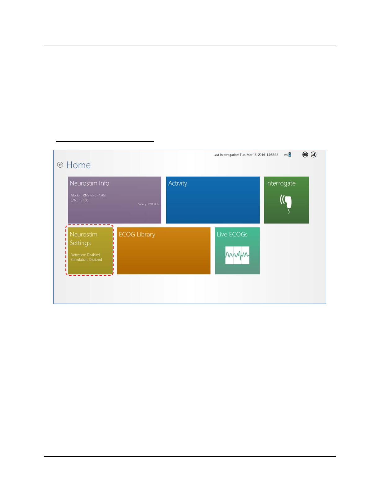
1. Select NEUROSTIM SETTINGS from the HOME screen.
RNS® System Programming Manual
Page 43
Tablet Instructions 39
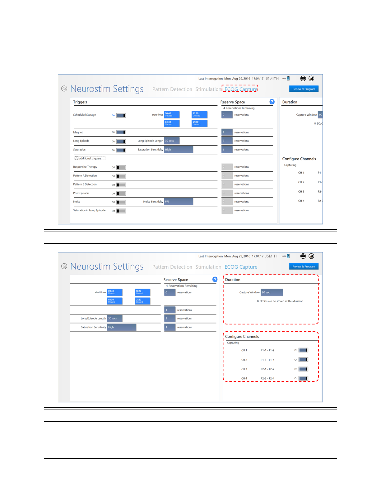
2. On the NEUROSTIM SETTINGS screen, select ECOG CAPTURE at upper right. The ECOG
CAPTURE screen opens.
Figure 26 ECoG Capture screen, left side. Swipe left to see right side.
Figure 27 Right side of ECoG Capture screen
RNS® System Programming Manual
Page 44
Tablet Instructions 40
3. Turn On Desired Channels: In the CONFIGURE CHANNELS area at lower right, select the
O
N/OFF switch next to the desired CHANNEL(S) (CH 1 through CH 4) to turn each channel on
or off as desired. Only the channels selected O
N will be recorded and stored.
4. Set Capture Duration: In the D
C
APTURE WINDOW field and select one of the capture duration options. After your selection,
the D
URATION area sho ws t he total duration (in seconds) and the number of ECoGs that can
URATION area at upper right (Figure 27 above), select the
be stored at this duration.
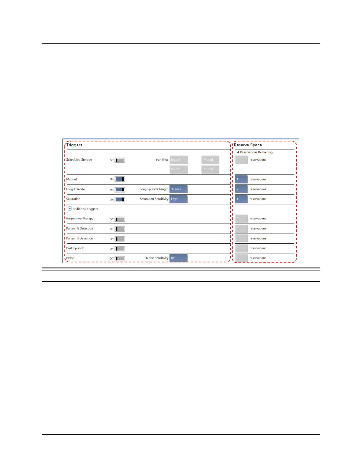
5. Set Capture Triggers: In the T
below), select the O
N/OFF switch to turn ON the triggers that you wish to initiate ECoG
RIGGERS area at upper left (Figure 26 above and Figure 28
capture.
Figure 28 Selecting ECoG Capture Triggers
There are three recommended ECoG triggers to be programmed at implant. The first is a
magnet swipe by the patient, which could indicate that a clinical seizure has occurred. The
others are saturation (high amplitude ECoG) and long episode (sustained changes in the
ECoG), both of which could indicate an electrographic seizure.
Commonly Used Triggers: The more commonly used triggers are listed first.
CHEDULED STORAGE: Initiate ECoG capture at up to four specific start times, which you
• S
can select using the fields to the right. Options are available in ten minute intervals using
24 hour time.
• M
AGNET: Initiates ECoG capture when the patient swipes the magnet over the
neurostimulator. If the patient swipes the magnet when they experience clinical
symptoms, selecting this trigger may be helpful in evaluating these events.
• L
ONG EPISODE: Initiates ECoG capture when a detected episode exceeds the duration
you select in the L
ONG EPISODE LENGTH field to the right. Duration options range from 1 to
120 seconds.
RNS® System Programming Manual
Page 45

Tablet Instructions 41
• SATURATION: Initiates ECoG capture when the ECoG amplitude exceeds the threshold
associated with the value you select in the S
sensitivity options are High, Medium, Low and Off. Selecting this trigger may be helpful
in troubleshooting the RNS
®
System.
ATURATION SENSITIVITY field to the right. The
Additional Triggers: Select the down arrow next to
ADDITIONAL TRIGGERS at lower left to
access the triggers below.
ESPONSIVE THERAPY: Initiates ECoG capture when electrical stimulation therapy is
• R
delivered in response to a detected eve nt. Selecting this trigger may be helpful in
determining if therapy was delivered appropriately as well as evaluating the result of
therapy delivered.
• P
ATTERN A DETECTION and PATTERN B DETECTION: These are separate triggers; each
initiates ECoG capture when a detected episode begins with the patterns designated as
Pattern A and Pattern B on the P
ATTERN DETECTION screen. Selecting a pattern trigger
may be helpful in evaluating the pattern detection settings.
OST-EPISODE: Initiates ECoG capture at the end of a detected episode. Selecting this
• P
trigger may be helpful in evaluating activity after an episode.
OISE: Initiates ECoG capture when the ECoG signal exceeds 60 Hz. Selecting this
• N
trigger may be helpful in troubleshooting the RNS
ATURATION IN LONG EPISODE: Initiates ECoG capture when the ECoG amplitude exceeds
• S
the threshold selected in the S
exceeds the duration selected in the L
ATURATION SENSITIVITY field during an episode that
ONG EPISODE LENGTH field.
6. Set Reservations for Each Trigger: In the R
ESERVE SPACE column to the right of each
®
System.
trigger (see Figure 28 above), select the reservations field and select the number of
reservations to make for each trigger. A reservation means that up to the specified number of
ECoGs will be stored for that trigger, and can only be overwritten by newer ECoGs of the
same trigger type. The total number of reservations available depends on the duration
selected in the D
URATION area at upper right.
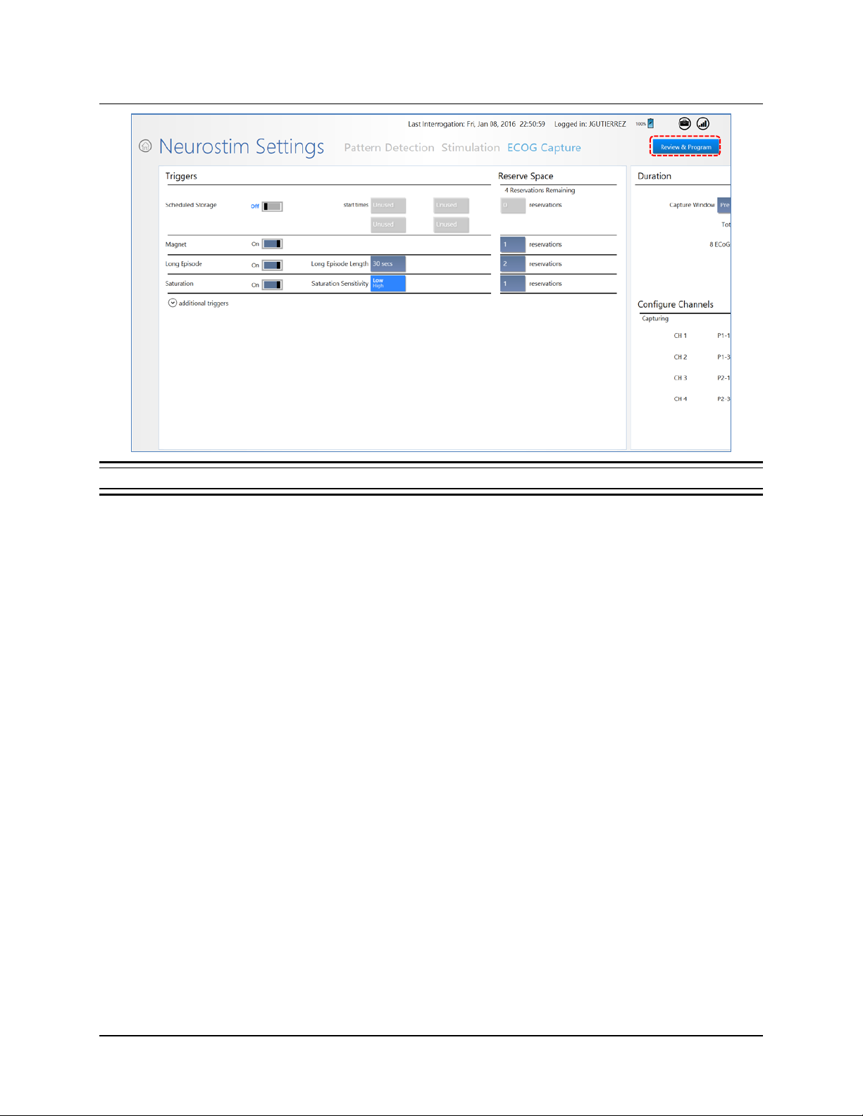
Recommended Initial ECoG Capture Settings
• Configure Channels for Capturing: All four channels ON
• Duration: 90
SECS
• Triggers On for ECoG Capture:
ONG EPISODE: Reservations = 2, Long Episode Length = 30 SECS
• L
AGNET: Reservations = 1
• M
ATURATION: Sat ur ati on Se nsiti vi t y: LOW, Reservations = 1
• S
• All other triggers OFF
RNS® System Programming Manual
Page 46
Tablet Instructions 42
Figure 29 ECoG Capture showing recommended initial settings
RNS® System Programming Manual
Page 47
Tablet Instructions 43
Program the Neurostimulator with the New Settings
The new settings are not sent to the neurostimulator until you complete this step.
Note: ECoG capture triggers are inactive during programming. Programming clears activity
information and ECoGs stored in the neurostimulator. If there is any new information, be sure
to interrogate the neurostimulator prior to programming.
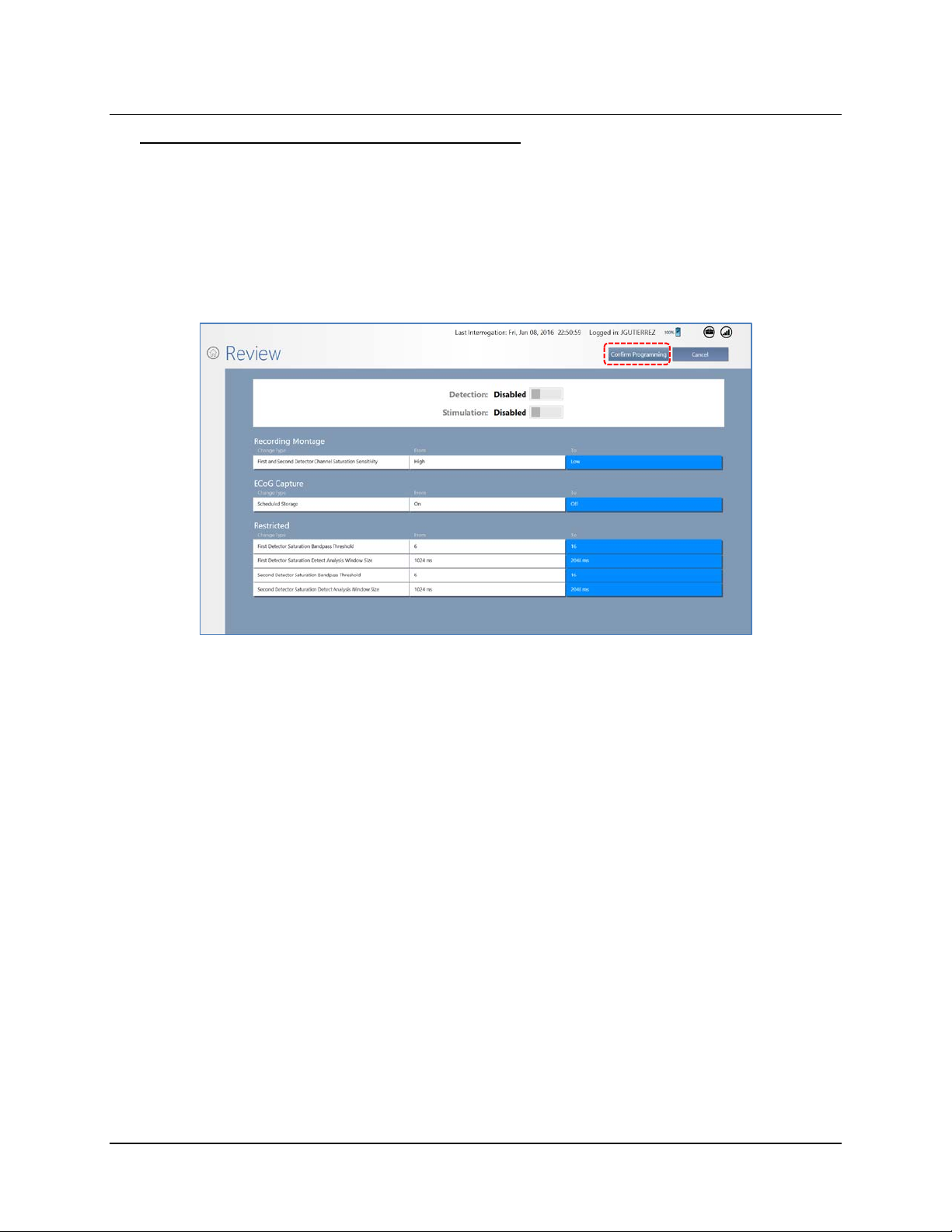
7. Select R
EVIEW & PROGRAM at upper right. The REVIEW screen opens. It lists all changes you
are about to program.
8. On the R
EVIEW screen, if you are satisfied with the new or changed settings, place the wand
within approximatel y 1 inch of the neurostimulator and select C
satisfied, select C
ANCEL to return to the previous screen.
ONFIRM PROGRAMMING. If not
ROGRAMMING NEUROSTIMULATOR dialog shows programming progress until complete.
The P
RECOMMENDATION FOR REVIEW OF INITIAL ECOG CAPTURE SETTINGS
ECoGs stored by the RNS® Neurostimulator during the first several days after implantation of the
neurostimulator and leads may not be representative of the patient’s typical baseline activity. ECoG
capture settings should be reviewed to ensure that the desired activity is being stored. If it appears that
ECoGs containing the desired activity are being overwritten by later events, instruct the patient to use the
remote monitor and wand to interrogate the neurostimulator immediately after each clinical seizure, or to
interrogate several times per day. Several interrogations per day during the first several days after
implantation will not have a signif icant impac t on batter y life.
• Recommendation: Review ECoGs on the PDMS to determine whether detections and storage
are optimal. If not, consider adjustments to the following triggers recommended to be O
ONG EPISODE LENGTH: Adjust the duration that triggers capture of a long episode.
• L
AGNET: Consider turning OFF the MAGNET trigger if the patient is not able to apply the
• M
magnet before or immediately after a clinical seizure, or if ECoGs capt ured b y thi s trigger ar e
not useful. Magnet swipes will still be counted and reported in the diagnostics.
RNS® System Programming Manual
N initially.
Page 48

Tablet Instructions 44
• DURATION: Select a briefer CAPTURE WINDOW value to yield more stored ECoGs, or a
engthier value to yield fewer stored ECoGs.
l
If you make changes, be sure to follow the steps above to review and program the new settings into the
neurostimulator.
CONFIGURE PATTERN DETECTION: DEFINE AND MODIFY DETECTION SETTINGS
Pattern detection settings are used by the RNS® Neurostimulator to recognize epileptiform activity as
defined by the physician. To configure pattern detection means to select specific ECoG patterns to be
detected, and then to program the system to detect these patterns. Configuring pattern detection is a
prerequisite for electrical stimulation therapy, but it does not require you to enable therapy.
Note: A pattern defines the type of ECoG activity to be detected.
Note: When defining or modifying a detection set, the programmer and the PDMS are able to
automatically simulate detection on all ECoGs stored for a patient. Simulation is displayed for
groups of six ECoGs at a time, with the user able to navigate through all ECoGs for that patient.
Note: Although detection sets can be created and modified using the PDMS either in a web
browser or on the programmer, only the programmer can be used to program the new settings
into the neurostimulator. When you select a new detection set that was created on the PD MS , it is
not necessary to re-run simulation on the programmer.
Configuring pattern detection has three phases:
• Phase 1: Select a Default Detection Set upon First Use on page 45, you select one of the
three default detection sets to gather an initial collection of ECoGs. This is usually configured and
programmed in the operating room immediately after implantation.
• Phase 2: Define a Pattern Detection Set on page 48, after initial ECoGs have been stored, you
review the stored ECoGs and identify the specific ECoG patterns to be detected. Using the
SimpleStart Feature, the system provides a s
as you exercise clinical judgment to define detection settings. It suggests a starting point only. It
does not preempt nor replace your clinical judgment. This is usually programmed at the first visit
post-implantation.
• Phase 3: Customize Pattern Detection on page 52, you repeat the process of reviewing stored
ECoGs and adjusting the parameters of each pattern to optimize detection of ECoG activity for
this patient. This is programmed at any visit after phase 2.
Note: For all settings, changed settings are indicated by blue buttons. Gray buttons indicate
settings have not changed.
o put these three phases in context:
T
Immediately after implantation of the neurostimulator, you select a default detection set in Phase 1, in
order to collect ECoGs with activity of interest specific to the patient, and ECoGs with baseline activity.
After collecting sufficient ECoGs, you identify the specific electrocorticographic patterns to be detected
and then, in Phase 2, the system provides a starting point for establishing a patient-specific detection set.
You may then modify the parameters of the suggested starting detection set to make detection more or
less sensitive, or to detect earlier or later.
tarting point for this process. It is a tool to assist you
RNS® System Programming Manual
Page 49
Tablet Instructions 45
In future visits, after collecting additional ECoGs, you then, in Phase 3, iterate to improve detection (and,
once responsive therapy has been enabled, to improve clinical response) by making small, incremental
changes to detection parameters with the sliders or M
Note: Typically, physicians repeat earlier phases (Phase 1 or Phase 2) only if they observe a new
type of ECoG activity of interest that requires an additional detector; or if a good clinical response
has not been obtained and they wish to start over.
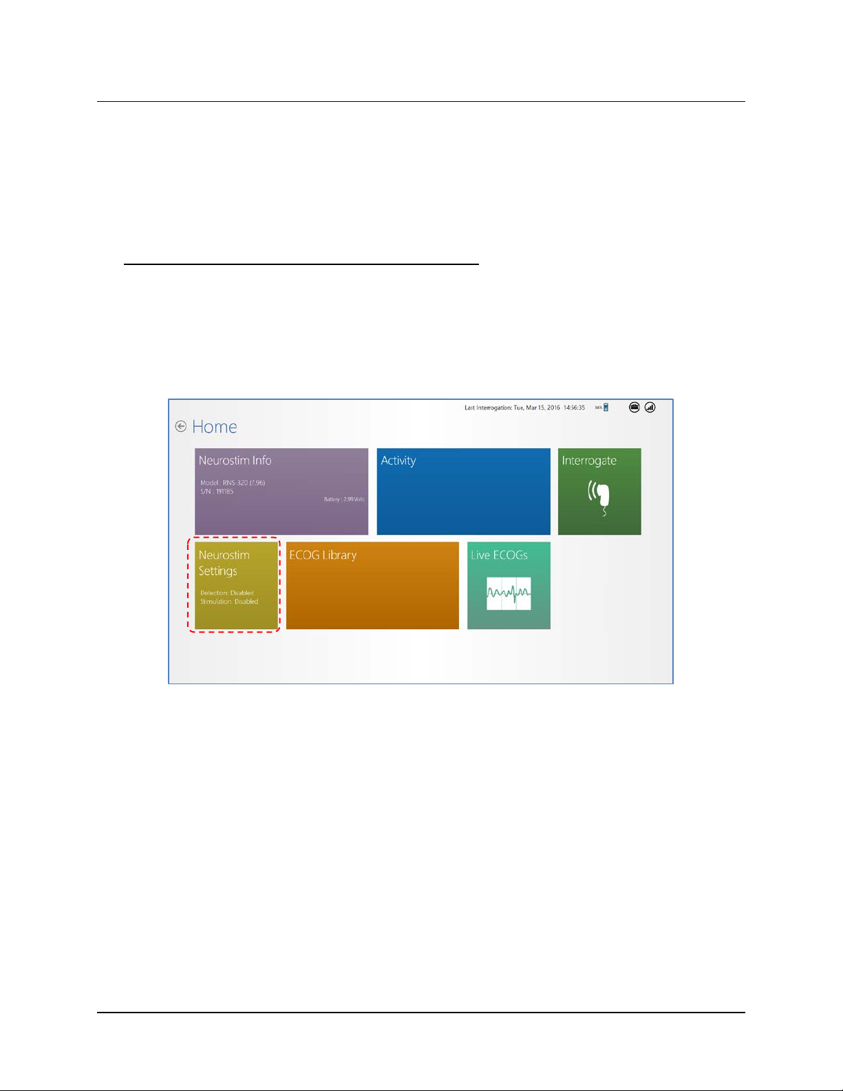
Phase 1: Select a Default Detection Set upon First U se
Upon first use of the tablet for each patient, the patient has no saved ECoGs from which to select a
pattern for detection, and so you must select one of three default detection sets. This is usually
configured in the operating room immediately after implantation. T he def ault sets are used to gather
an initial set of ECoGs for a patient, which you can then use in a subsequent visit to define a pattern
detection set specific to the patient. If you have already performed these steps once, proceed to the
next section, Phase 2: Define a Pattern Detection Set.
ORE CONTROLS.
1. Select N
EUROSTIM SETTINGS from the HOME screen.
RNS® System Programming Manual
Page 50
Tablet Instructions 46
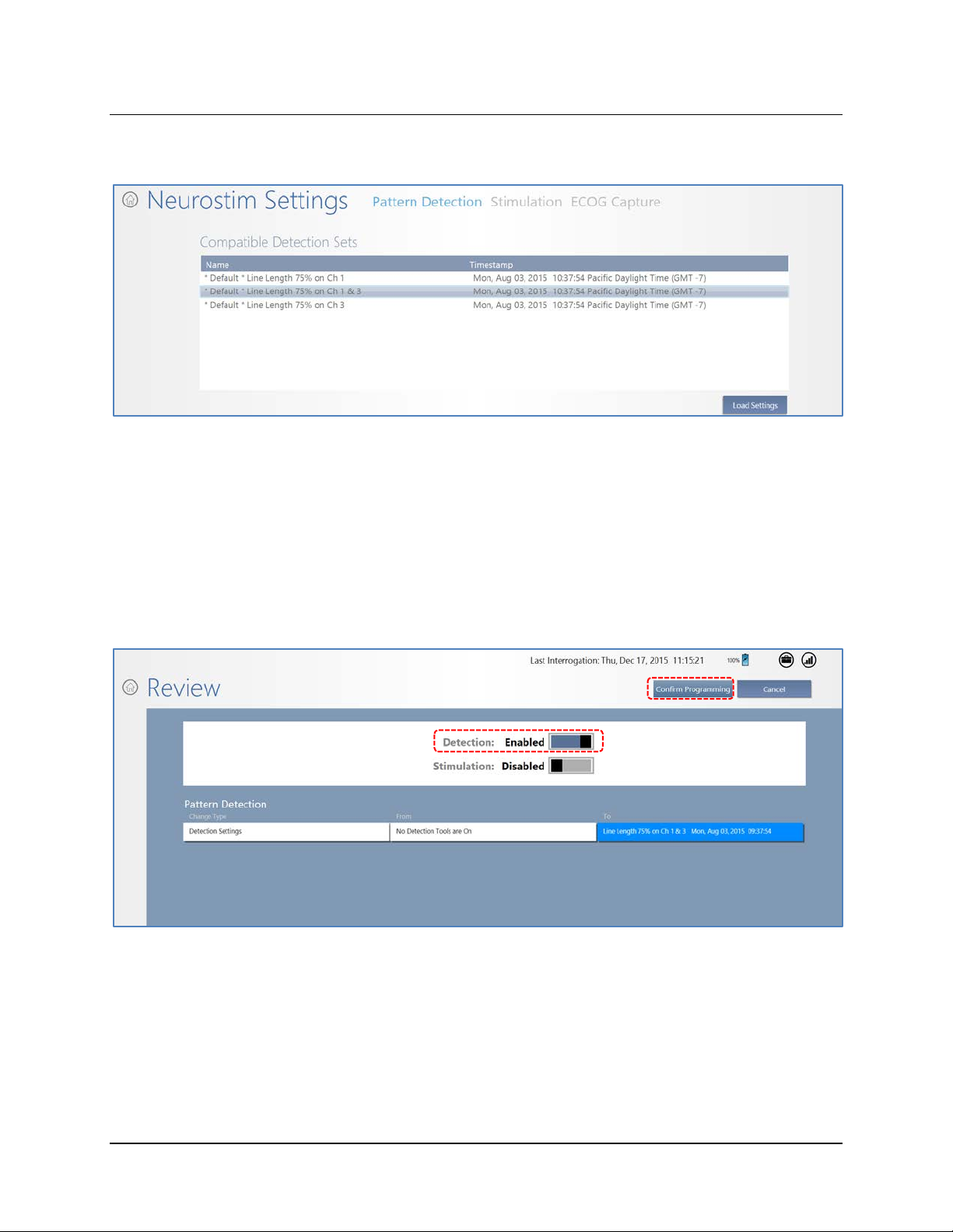
2. On the NEUROSTIM SETTINGS screen, select PATTERN DETECTION at upper center. A list of
three C
3. Select one of the three default detection settings. In the usual case, a patient has two active
leads to be configured, and therefore the recommended default pattern is P
75% ON CH 1 & 3 (DEFAULT), the second item in the list. (If only one lead is implanted, this
two-channel option will not appear in the list.) The other default patterns detect on only one
lead.
• Power change 75% is a detection setting that captures any large changes in the signal
OMPATIBLE DETECTION SETS appears.
OWER CHANGE
that clinicians can program and optimize as detection patterns.
4. Select L
screen. The R
5. On the R
OAD SETTINGS at lower right, then REVIEW & PROGRAM at upper right on the next
EVIEW screen opens.
EVIEW screen, make sure DETECTION is ENABLED. Then, if you are satisfied with the
new settings, place the wand within approximately 1 inch of the neurostimulator and select
C
ONFIRM PROGRAMMING. If not satisfied, select CANCEL to return to the previous screen.
RNS® System Programming Manual
Page 51
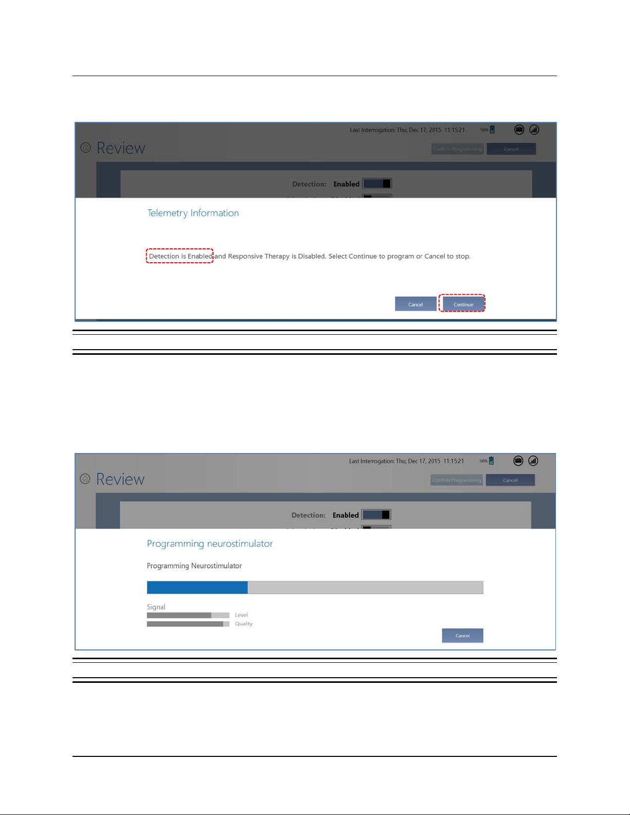
Tablet Instructions 47
When you confirm programming, a TELEMETRY INFORMATION dialog reports that “Detection is
Enabled and Responsive Therapy is disabled,” and prompts you to select C
Figure 30 Telemetry Information dialog to confirm programming again
ONTINUE or CANCEL.
6. Make sure the message reports that DETECTION is ENABLED, keep the wand in place and
select C
ONTINUE to proceed with programming, or CANCEL to cancel programming and return
to the previous screen.
When you select C
ONTINUE, the PROGRAMMING NEUROSTIMULATOR dialog shows programming
progress.
Figure 31 Programming neurostimulator dialog shows progress of programming
When complete, you return to the list of COMPATIBLE DETECTION SETS. Initial configuration is
complete. (You can select a different default setting and redo initial configuration if desired.)
RNS® System Programming Manual
Page 52
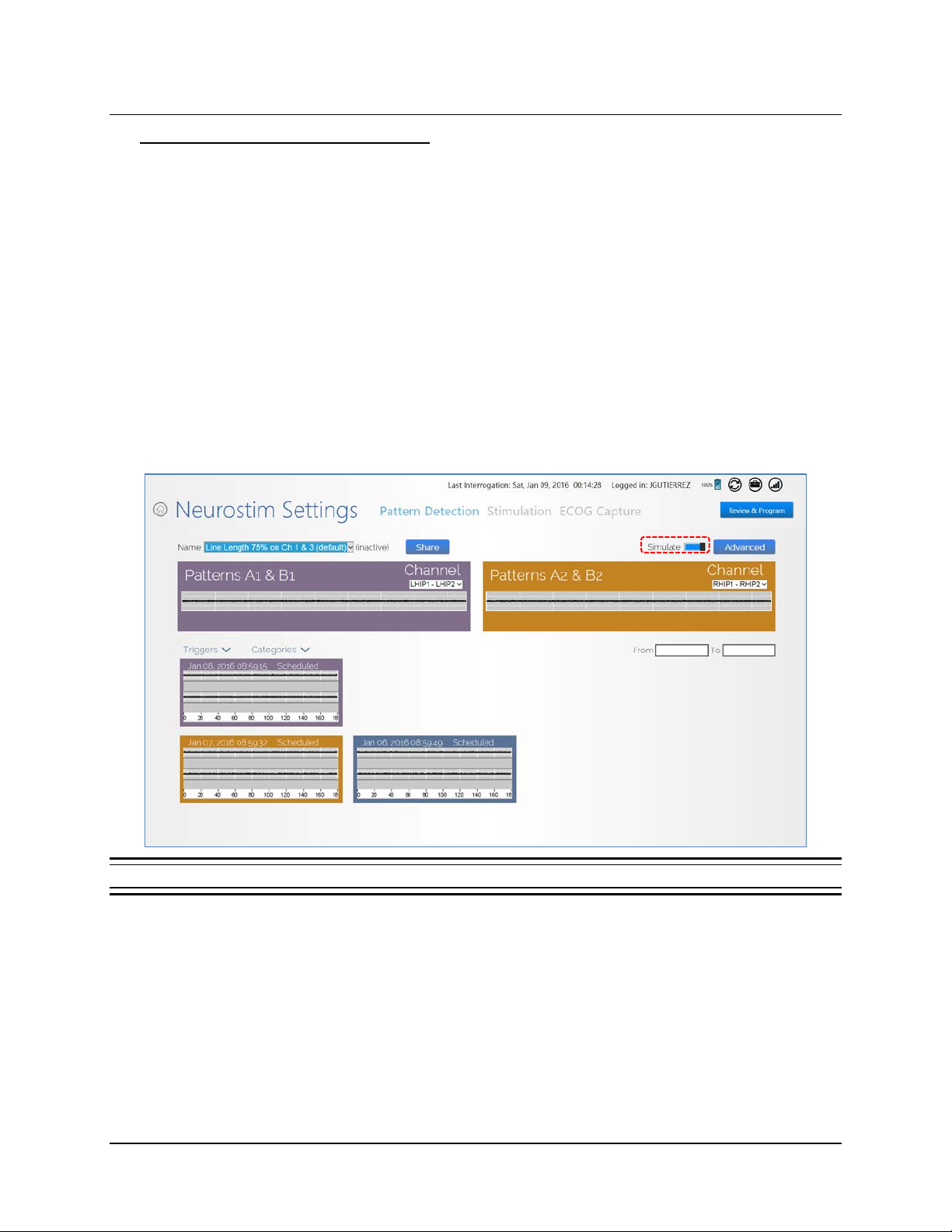
Tablet Instructions 48
Phase 2: Define a Pattern Detection Set
Note: You must be connected to the PDMS (via the Internet) to define a pattern detection set. If
not, you can program only a default detection set or a detection set previously defined and
downloaded to the tablet. If you are not connected to the Internet, see Connect to the Internet
for PDMS Access on page 10.
At this point, the patient should have ECoGs stored in the PDM S from which to select specific
patterns for detection. A set of patterns you define and name is called a pattern detection set (or
simply a detection set). A pattern defines the type of ECoG activity to be detected. You can define up
to four patterns in a set, two patterns on each of two channels. The patterns defined on a specific
channel can operate only in that selected ECoG channel. Follow these steps to define a pattern
detection set.
1. Select N
2. On the N
P
ATTERN DETECTION screen opens.
EUROSTIM SETTINGS from the HOME screen,
EUROSTIM SETTINGS screen, select PATTERN DETECTION at upper center. The
Figure 32 Pattern Detection screen
• The NAME field at upper left identifies the currently active detection set, as indicated by
(
ACTIVE) next to the field. You can edit this set or select an inactive set to program by
selecting the N
AME field.
• The upper half of the screen provides tiles to select the current detection patterns and
channels; the tiles are named P
ATTERNS A1 & B1 (upper left) and PATTERNS A2 & B2 (upper
right).
• The lower half of the screen shows thumbnails of all ECoGs (if no filters are on) stored in the
PDMS that were captured using the current recording montage. (ECoGs stored in the PDMS
were uploaded after interrogations from the remote monitor or programmer.) You can filter
RNS® System Programming Manual
Page 53

Tablet Instructions 49
the ECoGs shown using the TRIGGERS and CATEGORIES menus at left center, and/or by date
range using the F
ROM and TO fields at middle right.
• The S
IMULATE button at upper right (next to ADVANCED) is switched ON (blue) by default,
which enables simulations of detections to be shown on all ECoGs shown on this screen.
3. To define or change a detection set, select the desired detection set in the N
AME field at
upper left.
• The detection set may be one of the three default detection sets to be used as a starting point
for configuration; or it may be a detection set created and saved previously.
• If you don’t want to modify the detection set you chose, you can program the detection set
right away: Select R
approximately 1 inch of the neurostimulator, follow the prompted steps to C
EVIEW & PROGRAM at upper right and, while holding the wand with in
ONFIRM
PROGRAMMING and CONTINUE sending the new settings to the neurostimulator.
4. Use the D
the D
• Select one of the two P
EFINE PATTERNS dialog to define or modify a detection set. There are two routes to
EFINE PATTERNS dialog.
ATTERN tiles at the top to go there directly, or
• Select one of the ECoG thumbnails at the bottom to open its ECoG dialog, which is named by
its date and trigger type, and then select one of the two M
ODIFY buttons (A1 & A2, B1 & B2)
at upper right. (You can also use the ECoG dialog to assign the ECoG to a category if
desired.)
If You Selected a New ECoG First
5. If you selected a new ECoG first and selected a MODIFY button, a SELECT CHANNEL dialog
opens. Touch within the channel that has a pattern to detect. Then the D
EFINE PATTERNS
dialog opens.
RNS® System Programming Manual
Page 54
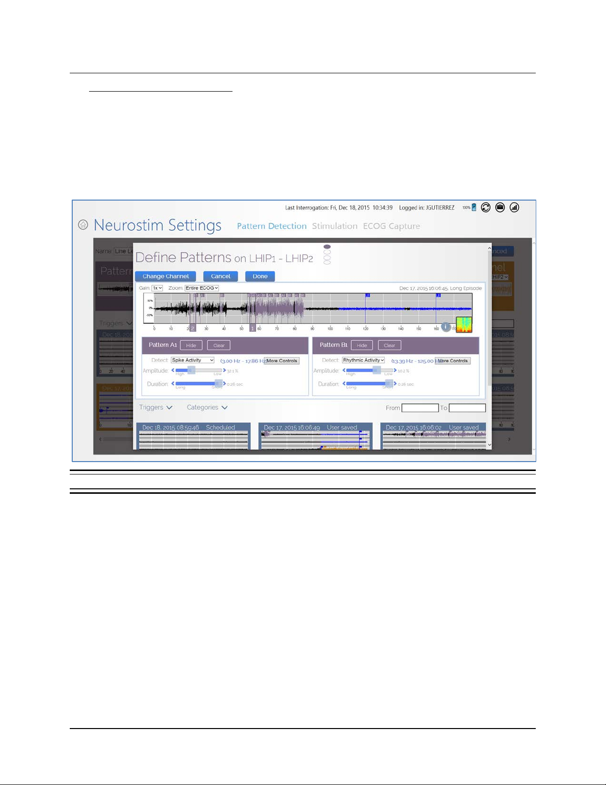
Tablet Instructions 50
Using the Define Patterns Dialog
Note: A pattern defines the type of ECoG activity to be detected.
6. In the D
EFINE PATTERNS dialog, the upper portion shows the ECoG in the selected channel.
Touch on the point of the ECoG where you would like detection to occur. Starting from the
point where you touch, a 3-second window of time (or region of i nterest, ROI) is bracketed on
the ECoG. This touch feature to bracket a 3-second region of interest is called the SimpleStart
Feature.
Figure 33 Define Patterns dialog
• The 3-second window bracketed on the ECoG is the patter n you are identifying for
detection; it should contain the type of pattern you would like to detect.
• Each 3-second window is identified as one of the four possible patterns you can define
A1, A2, B1 or
and B patterns are defined on different leads.)
A
B2. (The 1 and 2 indicate the first and second ROI you select. Typically th
• You can touch on the window identifier (A1, A2, B1 or B2) and slide the window left or
right to place it where it gives the desired simulated detection results. Note that th
s
oftware may apply a different suggested detection tool when you move the window.
Note: You cannot select a 3-second window within the first 5 seconds of an ECOG, bec aus e the
software looks for differences in the ECOG data before the 3-second window and needs sufficient
preceding data to determine this difference. If you touch before 5 seconds in the ECoG, the
software places the window starting at the 5-second mark.
RNS® System Programming Manual
,
e
e
Page 55

Tablet Instructions 51
• Normally you want to touch near the beginning of the pattern in order to define a pattern that
will be detected promptly after it begins. Detection settings should promptly detect ECoG
activity and not detect on baseline activity.
The software automatically applies a suggested detector (shown in the D
ETECT field) and
settings that fit the waveform pattern in that 3-second window (or region of interest, ROI), and
simulates detection, showing the detection flags the chosen pattern would apply to this
ECoG—and to all the patient’s other stored ECoGs shown in smaller size below. It is
recommended to review simulated detection activity on an ensemble of stored ECoGs before
finalizing the detection setti ngs .
• To hide the simulation on the ECoG, select H
select C
LEAR.
IDE. To remove the selection on the ECoG,
• At any point, you can select a different ECoG by selecting an ECoG thumbnail along the
bottom; swipe left or right to view all available thumbnails.
• By default, if you define both patterns, detections will occur for both patterns on this channel.
The channel is indicated by the filled oval at top center of the dialog, from 1 to 4 top to
bottom. Use the C
HANGE CHANNEL button to change the channel on which to detect the
pattern.
Note: If simulating performance of a 2-channel detection set, be sure to select ECoGs that
contain ECoG activity patterns you wish to detect in both channels.
• Make adjustments to the parameters applicable to the detection tool using the sliders
available and observe the effects on the simulation. For S
PIKE ACTIVITY and RHYTHMIC
ACTIVITY, the sliders adjust AMPLITUDE (%) and DURATION (seconds). For POWER CHANGE, the
sliders adjust S
ENSITIVITY (%) and DETECT (seconds).
• All these detection parameters affect sensitivity. Adjustments that increase sensitivity
tend to increase how early and how often the pattern i s detecte d; adj ustments that
decrease sensitivity tend to decrease how early and how often the pattern is detected.
• Detection settings should be programmed for early detection of activity. Detection
settings that result in early activity detection usually also result in numerous detections;
this is expected and acceptable behavior.
• The parameter values are shown to the right of each slider. For all four parameters, lower
values result in greater sensitivity.
• The M
ORE CONTROLS button gives access to additional adjustment options and Advanced
Controls (see page 63).
7. Select D
ONE at upper right to close the DEFINE PATTERNS dialog. The detection set is not
saved until you save it in the next step.
RNS® System Programming Manual
Page 56
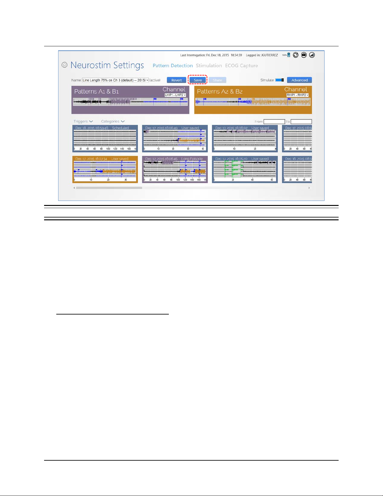
Tablet Instructions 52
Figure 34 Detection settings ready to be saved
Note: ECoG capture triggers are inactive during programming. Programming clears activity
information and ECoGs stored in the neurostimulator. If there is any new information, be sure
to interrogate the neurostimulator prior to programming.
8. Save and Program: Back in the N
name the detection set in the S
R
EVIEW & PROGRAM at upper right and, while holding the wand within approximately 1 inch of
the neurostimulator, follow the prompted steps to C
EUROSTIM SETTINGS screen, select SAVE at upper center;
AVE DETECTION SET dialog and select SAVE; then select
ONFIRM PROGRAMMING and CONTINUE
sending the new settings to the neurostimulator.
Phase 3: Customize Pattern Detection
To customize pattern detection is to refine detection settings to promptly detect the specific patterns
for this patient, and not detect on baseline activity, since detection serves as the basis for
neurostimulator treatment. On visits subsequent to Phase 2: Define a Pattern Detection Set, the
usual, systematic approach is to make small, incremental adjustments to individual parameters of a
detection pattern. The adjustment you make may be intended to increase or decrease how early and
how often the pattern is detected, based on your assessment of current detection activity as viewed
on stored ECoGs and on the Activity Screen (see page 23).
Note: Typically, physicians repeat earlier phases (Phase 1 or Phase 2) only if they observe a new
type of ECoG activity of interest that requires an additional detector; or if a good clinical response
has not been obtained and they wish to start over.
RNS® System Programming Manual
Page 57
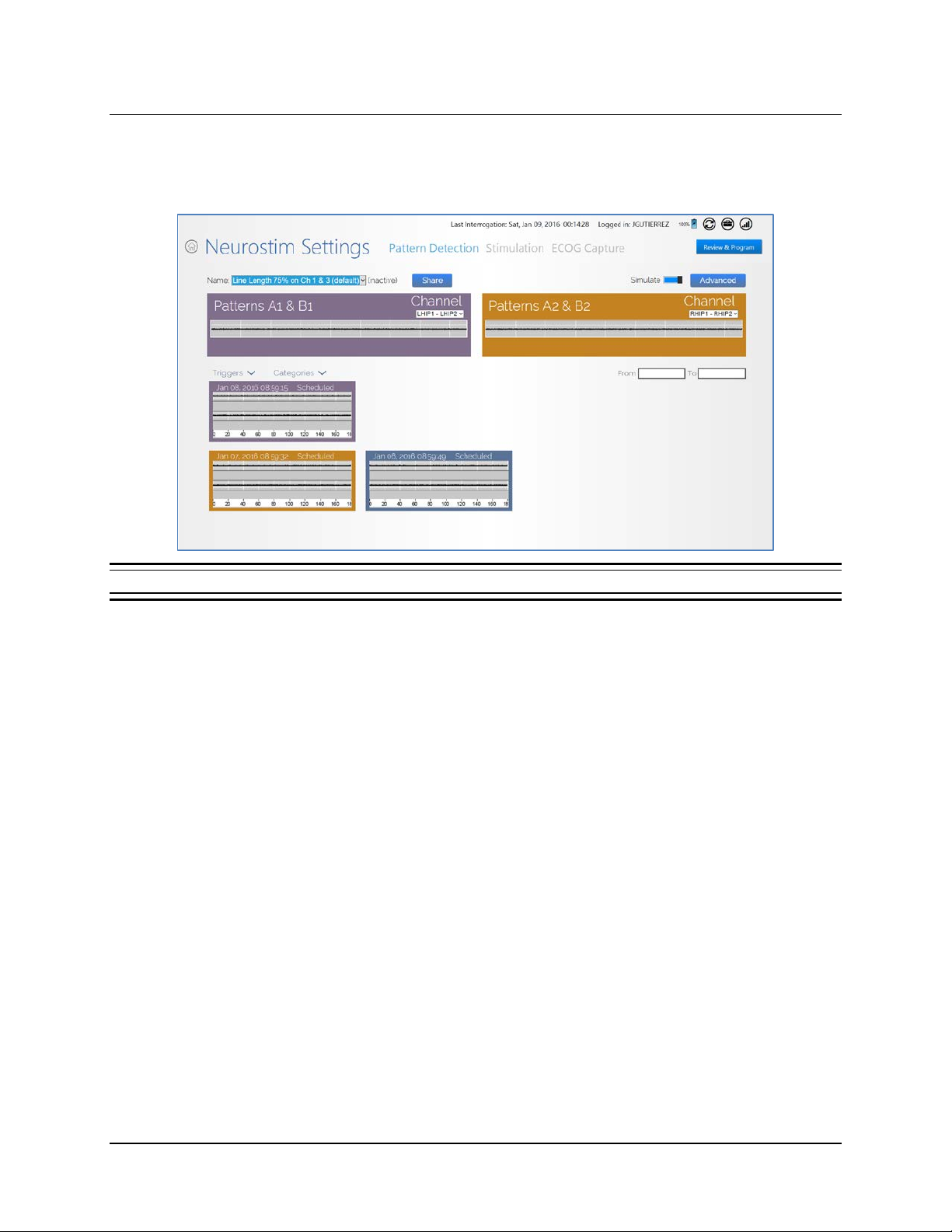
Tablet Instructions 53
1. Select NEUROSTIM SETTINGS from the HOME screen,
2. On the N
P
ATTERN DETECTION screen opens.
Figure 35 Pattern Detection screen
EUROSTIM SETTINGS screen, select PATTERN DETECTION at upper center. The
• The NAME field at upper left identifies the currently active detection set, as indicated by
(
ACTIVE) next to the field. You can edit this set or select an inactive set to program by
selecting the N
AME field.
Note: To customize the current pattern detection set, do not change the active detection set
shown by default in the N
AME field at upper left.
• The upper half of the screen provides tiles to select the current detection patterns and
channels; the tiles are named P
ATTERNS A1 & B1 (upper left) and PATTERNS A2 & B2 (upper
right).
• The lower half of the screen shows thumbnails of all ECoGs (if no filters are on) stored in the
PDMS that were captur ed using the cur re nt rec ord ing montage. You can filter the ECoGs
shown using the T
• The S
IMULATE button at upper right (next to ADVANCED) is switched ON (blue) by default,
RIGGERS and CATEGORIES menus at left center.
which enables simulations of detections to be shown on all ECoGs shown on this screen.
3. Select one of the two P
ATTERN tiles at the top to access the DEFINE PATTERNS dialog.
RNS® System Programming Manual
Page 58
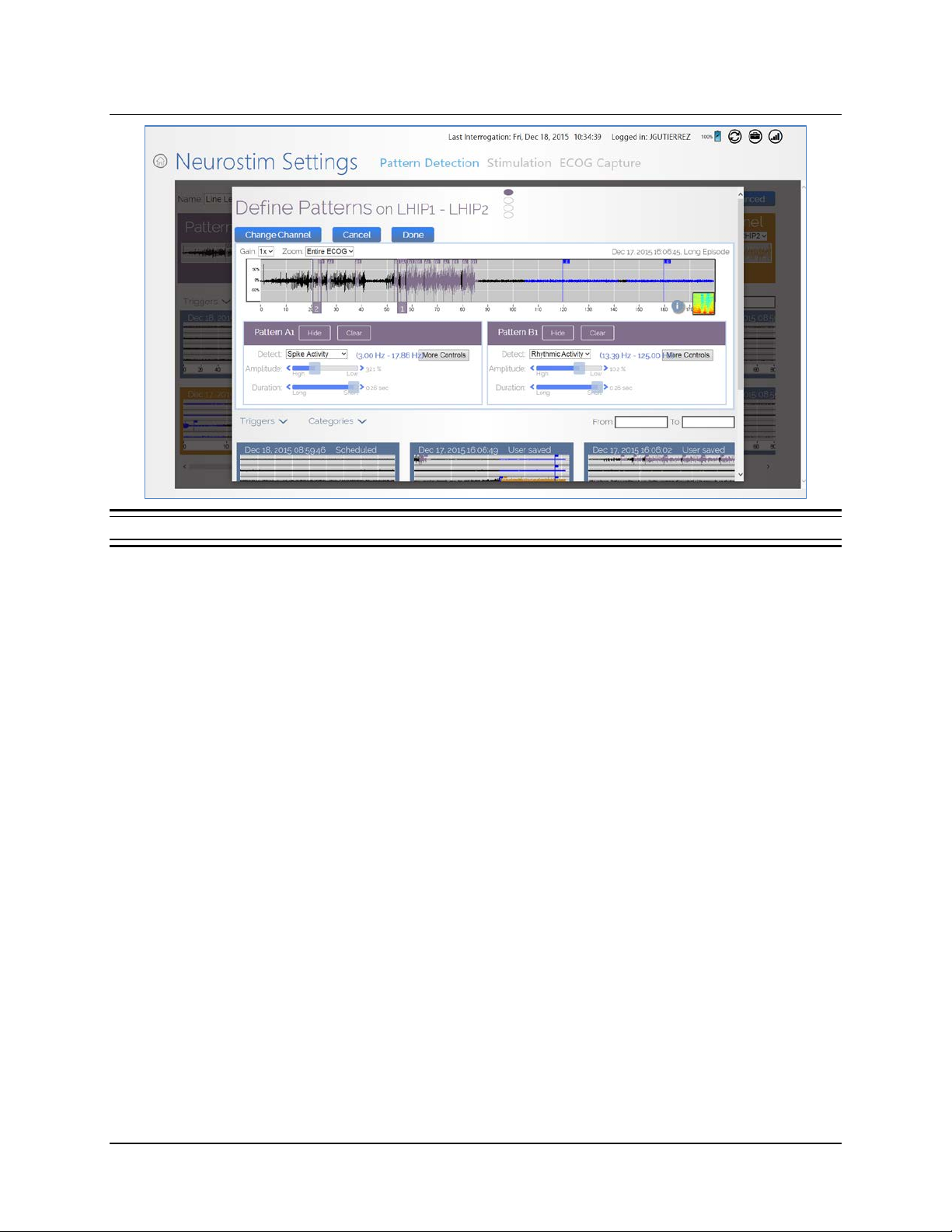
Tablet Instructions 54
Figure 36 Define Patterns dialog
4. In the DEFINE PATTERNS dialog, select and adjust the desired parameter using the sliders so
as to increase or decrease how early and how often the pattern is detected.
The software automatically simulates detection with the changed parameter as applied to this
ECoG and to the patient’s other stored ECoGs shown in smaller size below. It is
recommended to review simulated detection activity on an ensemble of stored ECoGs before
finalizing your adjustment.
• Swipe up to view the bottom of the dialog where the ECoGs appear with simulated
detection; swipe left or right to see more ECoGs if available. You can filter the ECoGs
using the T
RIGGERS and CATEGORIES menus, and/or the FROM and TO date range
fields.
RNS® System Programming Manual
Page 59
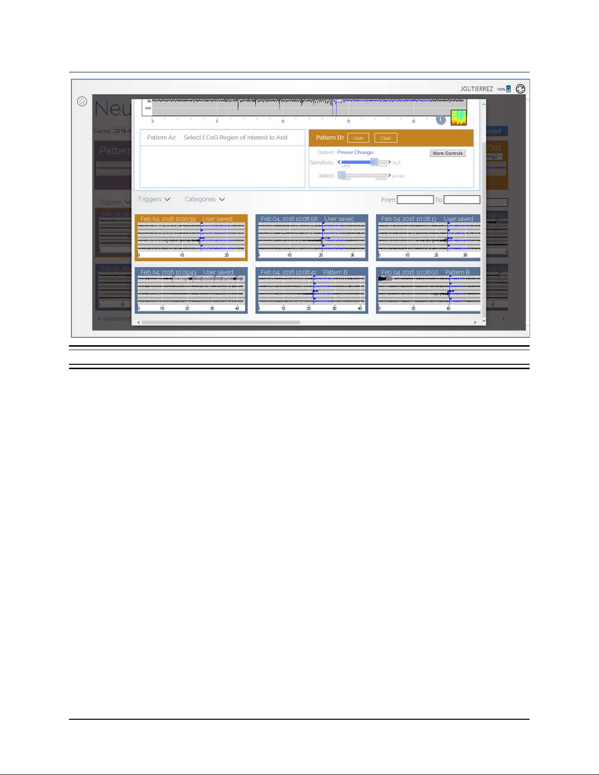
Tablet Instructions 55
Figure 37 Detection simulation in all ECoGs
• To hide the simulation on the ECoG, select HIDE. To remove the pattern on the ECoG, select
C
LEAR.
• Detection parameters that affect sensitivity are key: adjustments that increase sensitivity tend
to increase how early and how often the pattern is detected; adjustments that decrease
sensitivity tend to decrease how early and how often the pattern is detected.
• To adjust sensitivity, the two most common parameters to adjust are the ones with sliders
directly on the D
sliders adjust A
S
ENSITIVITY (%) and DETECT (seconds).
EFINE PATTERNS dialog. For SPIKE ACTIVITY and RHYTHMIC ACTIVITY, the
MPLITUDE (%) and DURATION (seconds). For POWER CHANGE, the sliders adjust
Note: The parameter values are shown to the right of each slider. For all four parameters, lower
values result in greater sensitivity. Make adjustments and observe the effects on the simulation.
• The M
ORE CONTROLS button gives access to additional adjustment options and advanced
settings.
5. Select D
ONE at upper right to close the DEFINE PATTERNS dialog. The detection set is not
saved until you save it in the next step.
6. Save and Program: Back in the N
rename the updated detection set if desired in the S
S
AVE. Then select REVIEW & PROGRAM at upper right and, while holding the w and with in
approximately 1 inch of the neurostimulator, follow the prompted steps to C
PROGRAMMING and CONTINUE sending the new settings to the neurostimulator.
EUROSTIM SETTINGS screen, select SAVE at upper center;
AVE DETECTION SET dialog, and select
ONFIRM
RNS® System Programming Manual
Page 60

Tablet Instructions 56
• After changing detection settings, the NEUROSTIM SETTINGS screen has a REVERT button next
to the S
AVE button. Select REVERT if you want to remove all changes to the detection settings
and revert to the current detection set.
DETECTION TOOLS AND DETECTORS
Note: Detection tools and detectors support you as you exercise clinical judgment to define
detection settings. Detectors and settings initially suggested by the software (as des cr ibed in
Phase 2 on page 48) offer a starting point only. The software does not preempt nor replace your
clinical judgm e nt.
In previous versions of programmer software, the physician selected a set of ECoGs with specific patterns
to be detected, chose a detection tool and settings, observed the simulated detections that would occur
on that set of ECoGs, and then repeated the proc
In the current version, when you use the SimpleStart Feature to select a waveform pattern to detect, the
software suggests a detector (one of POWER CHANGE, RHYTHMIC ACTIVITY or SPIKE ACTIVITY) and
associated settings as a proposed fit for that pattern. You use this procedure initially (in Phase 2: Define
a Pattern Detection Set, see page 48) to create a new detection set when you have first gathered
ECoGs containing the type of activity you wish to detect. This detection set is a suggested starting point
to assist you as you exercise clinical judgment to define detection settings. It suggests a starting point
only. It does not preempt nor replace your clinical judgment. The software also simulates the suggested
detector and settings on all of the patient’s stored ECoGs. By reviewing the simulated detection on an
ensemble of stored ECoGs, you can confirm that detection occurs when desired, or c hange the selected
pattern, detectors and/or s ettings to make detection occur when desired. Having defined up to four
detection patterns and associated settings, you then save them as a detection set. (Up to four detection
patterns on up to two channels comprise a detection set.)
ess iteratively to define a detection set.
Detection Tools and Detectors
The RNS® Tablet uses three kinds of detection tools: POWER CHANGE (page 57), BANDPASS (page
61), and A
REA (page 62).
• The P
OWER CHANGE detection tool (formerly line length) is used in the POWER CHANGE
detector.
• The B
ANDPASS detection tool is used in two detectors, RHYTHMIC ACTIVITY and SPIKE
ACTIVITY.
REA detection tool is infrequently used and can be selected only manually from the
he A
• T
D
EFINE PATTERNS dialog (select MORE CONTROLS > ADV CONTROLS).
Note: R
detected by the B
an ROI, but can be manually programmed by selecting M
HYTHMIC ACTIVITY and SPIKE ACTIVITY both are types of ECoG activity that can be
ANDPASS tool. The AREA too l is not us ed to gener ate a suggested detector from
ORE CONTROLS > ADV CONTROLS.
The table below summarizes this information.
RNS® System Programming Manual
Page 61
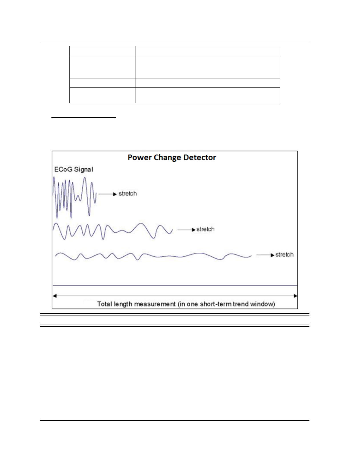
Tablet Instructions 57
Detection Tool
Detectors Used With
L
)
BANDPASS
Rhythmic Activity and Spike Activity
suggested detector)
POWER CHANGE
(FORMERLY LINE
ENGTH
Power Change
AREA
Area (configured manuall y onl y, not used as a
Power Change Detector
To understand how the power change detector works refer to Figure 39. Imagine the ECoG as a
string that can be stretched so the length can be measured. ECoGs w ith higher amplitude or
frequency oscillations will have longer length.
Figure 38 An illustration of the Power Change dete ct or
RNS® System Programming Manual
Page 62
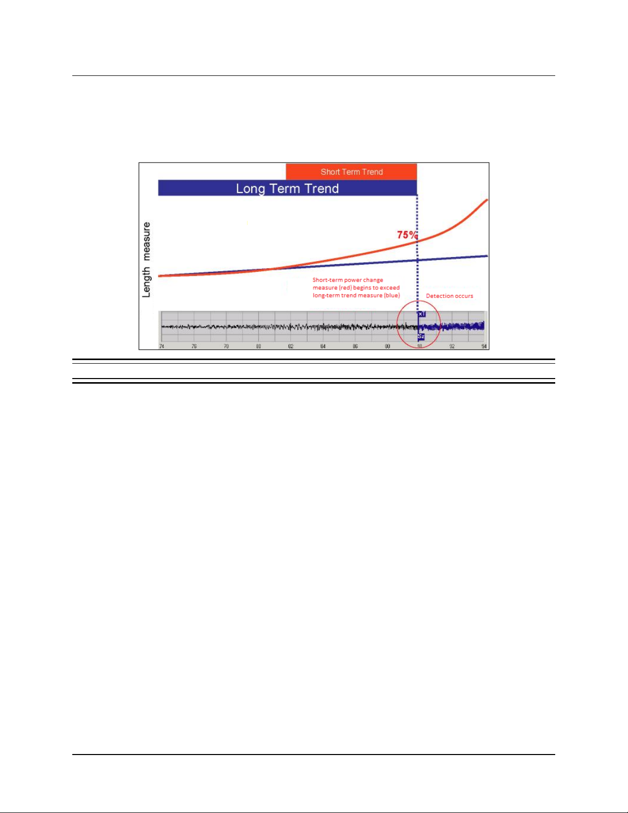
Tablet Instructions 58
The ECoG in the bottom of Figure 39 below shows a developing seizure that corresponds in time
with the short-term power change trend line (red) and the long-term power change trend line (blue).
The power change detector works by comparing the normalized ECoG length (length per second) in a
short-term trend window (typically 1 to 4 seconds, red line in graph) to the normalized ECoG length in
a long-term trend window (typically 1 to 2 minutes, blue line in graph).
Figure 39 Power Change detector example
Detection occurs when the difference between the short-term and long-term trend windows exceeds a
programmed S
earlier and more frequent detections. The D
(in seconds). Shorter D
ENSITIVITY percentage (typically 37.5% to 100%). Lower SENSITIVITY settings result in
ETECT setting specifies the length of the short-term trend
ETECT sett in gs res ult in earl ier and m or e frequent detec t io ns .
RNS® System Programming Manual
Page 63
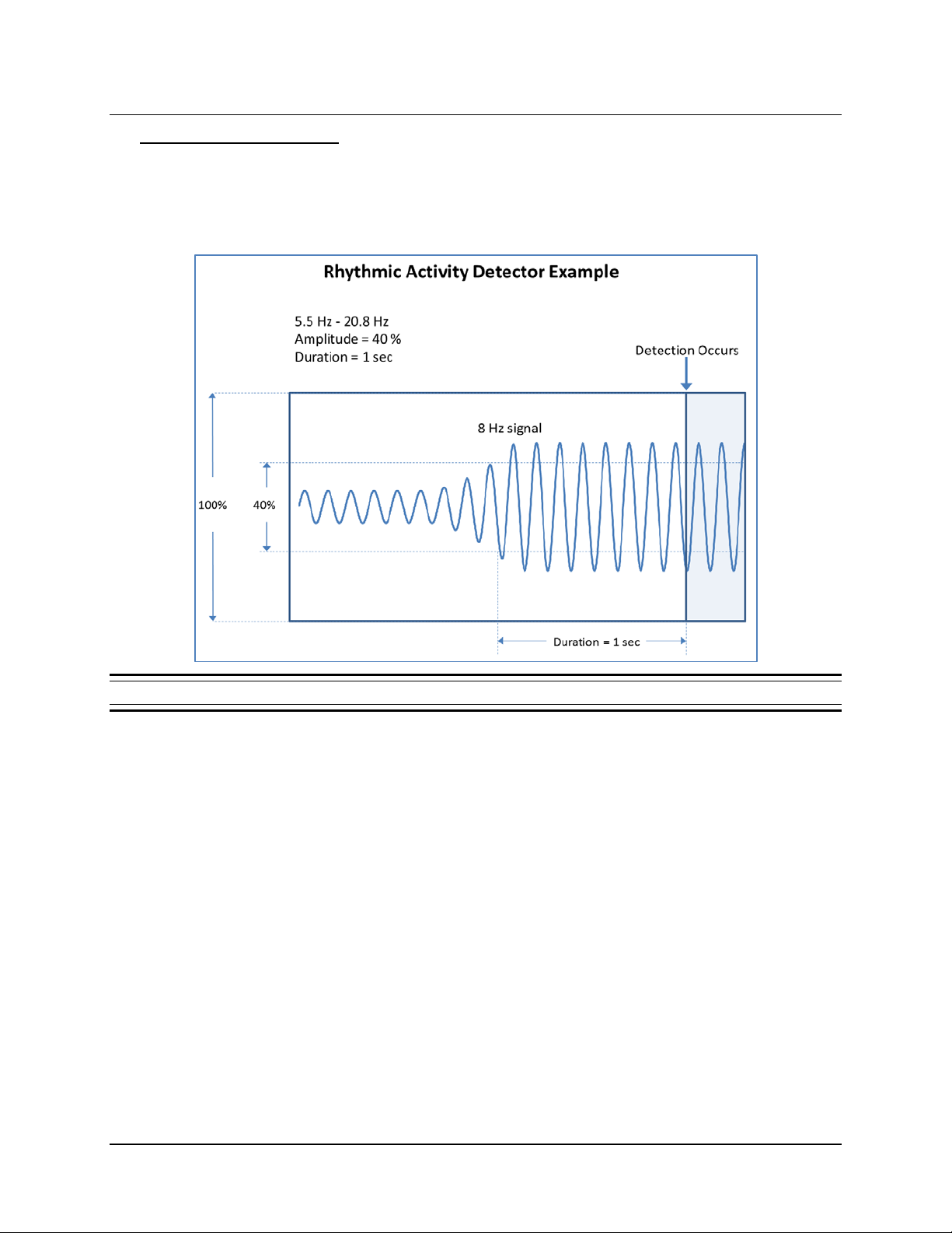
Tablet Instructions 59
Rhythmic Activity Detector
The Rhythmic Activity detector provides highly specific and early detection of rhythmic activity within a
defined bandwidth. It acts like a frequency filter and can therefore be used to detect activity within
specific frequency bands (theta, alpha, beta, and gamma). To understand how the Rhythmic Activity
detector works refer to Figure 40.
Figure 40 Rhythmic Activity detector example
The Rhythmic Activity detector analyzes t he ECoG to deter mine when a signal is present within a
specified bandwidth that meets specified amplitude and duration requirements. Four configurable
parameters define the Rhythmic Activity detector operation: the M
INIMUM FREQUENCY and MAXIMUM
FREQUENCY that define the bandpass, the AMPLITUDE, and the DURATION. Detection occurs when a
signal within the bandwidth exceeds the A
MPLITUDE for the minimum DURATION. As DURATION is
increased, the detector becomes less sensitive because it will take longer for a signal at a given
frequency to be detected. As D
it will take less time for a signal at a given frequency to be detected. As A
detector becomes less sensitive because lower amplitude signals will be rejected. As A
URATION is decreased, the detector becomes more sensitive because
MPLITUDE is increased, the
MPLITUDE is
decreased, the detector becomes more sensitive because lower amplitude signals will be accepted.
RNS® System Programming Manual
Page 64
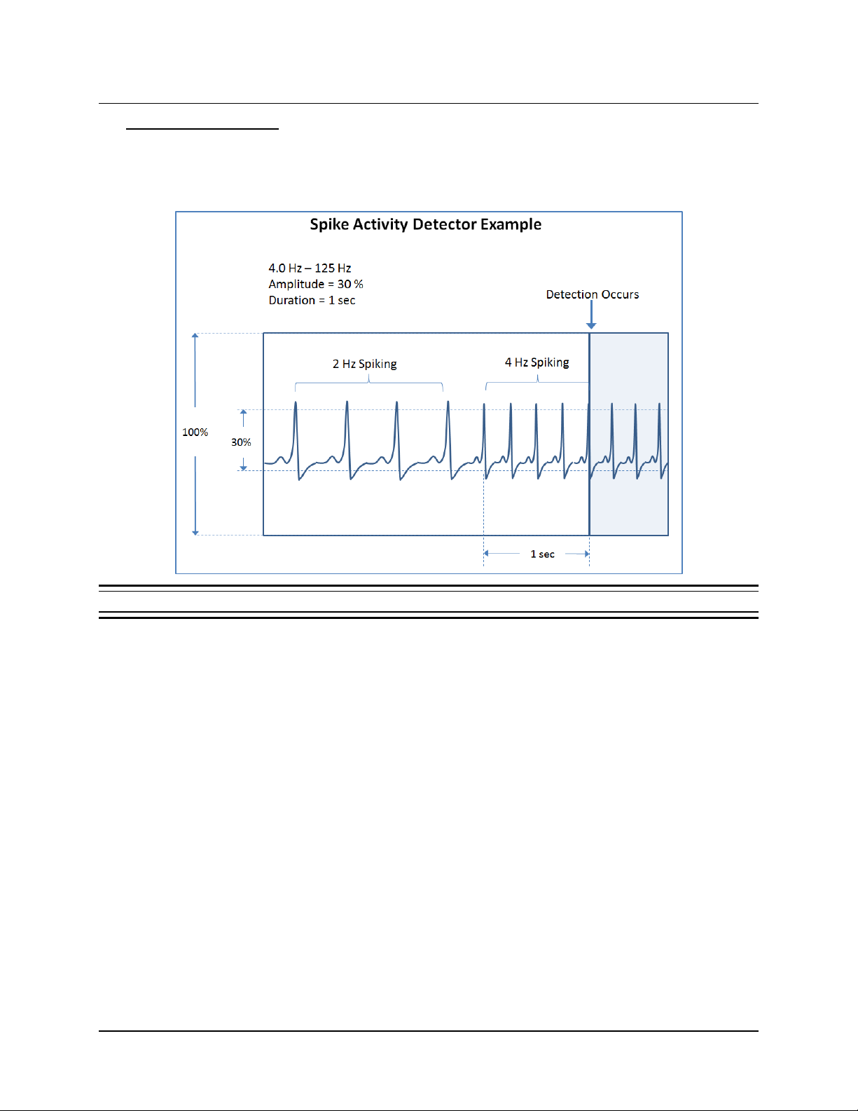
Tablet Instructions 60
Spike Activity Detector
The Spike Activity detector functions in a manner very similar to the Rhythmic Activity detector, but it
is optimized for the faster transients that comprise spikes. To understand how the Spike Activity
detector works refer to Figure 41.
Figure 41 Spike Activity detector example
The Spike Activity detector analyzes the ECoG to determine when a signal is present within a
specified bandwidth that meets specified amplitude and duration requirements. Four configurable
parameters define the Spike Activity detector operation: the M
INIMUM FREQUENCY and MAXIMUM
FREQUENCY, the AMPLITUDE, and the DURATION. The MINIMUM FREQUENCY defines the slowest spiking
rate that can be detected. The M
AXIMUM FREQUENCY defines the upper passband for the detector.
Because the signal frequency content of the fast transient portions of spikes are generally much
higher than the spike rate, the M
AXIMUM FREQUENCY usually needs to be set much higher than the
spike rate. Detection will occur when spikes meeting the frequency requirements also exceed the
A
MPLITUDE for the DURATION. As DURATION is increased, the detector becomes less sensitive
because it will take longer for detection to occur. As D
URATION is decreased, the detec tor becomes
more sensitive because it will take less time for a detection to occur.
RNS® System Programming Manual
Page 65
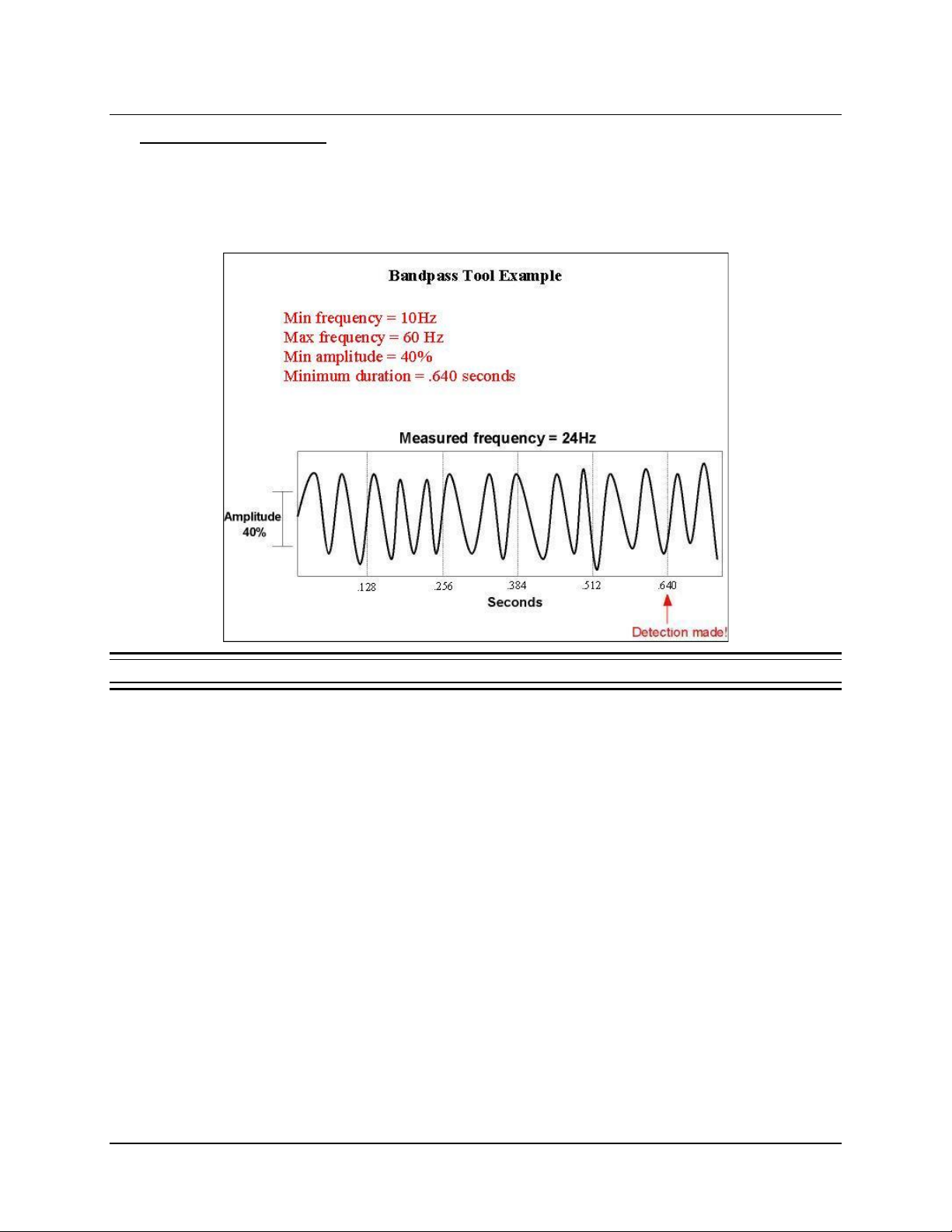
Tablet Instructions 61
Bandpass Detection Tool
The Bandpass detection tool provides highly specific and early detection of rhythmic and spiking
activity. It acts like a frequency filter and can therefore be used to detect activity within specific
frequency bands (for example, theta, alpha, beta, and gamma). The R
ACTIVITY detectors use the Bandpass tool.
HYTHMIC ACTIVITY and SPIKE
Figure 42 Bandpass detection tool example.
RNS® System Programming Manual
Page 66
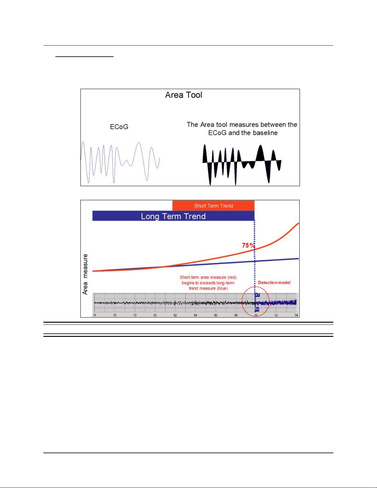
Tablet Instructions 62
Area Detection Tool
The AREA detection tool can be selected only manually from the DEFINE PATTERNS dialog (select
M
ORE CONTROLS > ADV CONTROLS). It is not used as a suggested detector by the software. The AREA
detection tool measures the area between the ECoG and the time axis (see Figure 43).
Figure 43 Area detection tool example
The Area detector operates by comparing the normalized ECoG area (area per second) in a shortterm trend window (typically 1 to 4 seconds) to the norm alized ECoG area in a long-term trend
window (typically 1 to 2 minutes). Detection occurs when the difference between the short-term and
long-term trend windows exceeds a programmed threshold (typically 37.5% to 100%).
RNS® System Programming Manual
Page 67
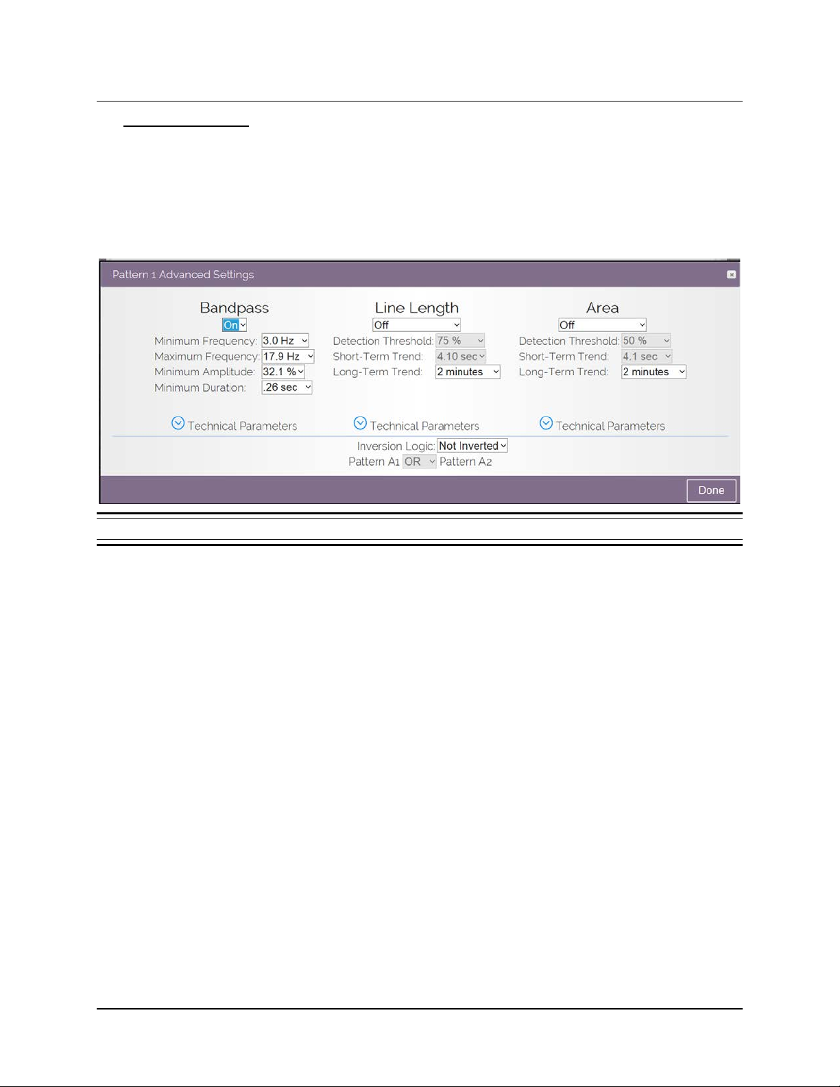
Tablet Instructions 63
Advanced Controls The physician has access to advanced controls from the DEFINE PATTERNS dialog. Select MORE
CONTROLS > ADV CONTROLS to open the ADVANCED SETTINGS dialog for the pattern you are currently
defining, which gives access to additional settings for the detection tools B
and A
REA. (AREA can be selected only in this dialog.) Select the down-arrow next to TECHNICAL
PARAMETERS to access even more settings. You can select more than one tool for use at the same
time in this dialog.
ANDPASS, POWER CHANGE
Figure 44 Bandpass, Power Change and Area settings, in Advanced Settings dialog
RNS® System Programming Manual
Page 68
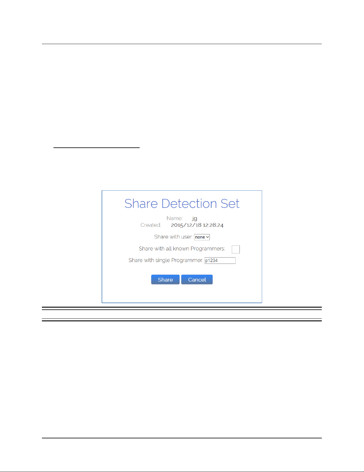
Tablet Instructions 64
SHARE AND/OR DOWNLOAD A DETECTION SET
This section explains how to share a detection set with the users or programmers you select, and how to
download a shared detection set. For example, use this feature when more than one physician is treating
a patient.
You must be connected to the PDMS (via the tablet or a web browser on a personal computer) to define
or modify a custom detection set, and by default, these are saved to the PDMS only—n ot loc al ly. If you
are connected to the PDMS during programming, you can program the neurostimulator with any detection
set saved under the current username or saved to the programmer you are using. However, if you are not
connected to the PDMS (offline) during programming, you can program only the pre-programmed default
detection sets or those detection sets previously downloaded from the PDMS to the programmer.
Steps to Share a Detection Set
1. Whenever connected to the PDMS, either on a programmer or using a web browser on a
personal computer, you can share the currently selected detection set by selecting the S
button on the N
EUROSTIM SETTINGS > PATTERN DETECTION screen. The SHARE DETECTION SET
dialog opens.
HARE
Figure 45 The SHARE DETECTION SET dialog
RNS® System Programming Manual
Page 69
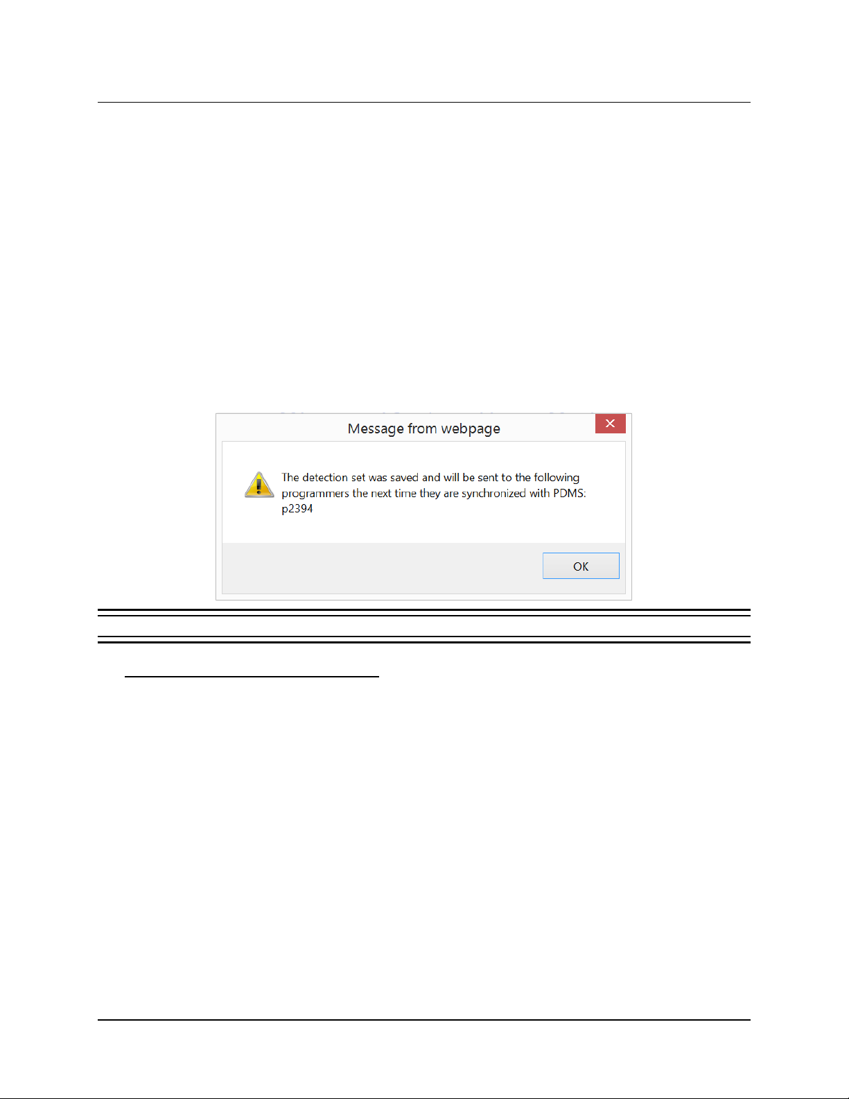
Tablet Instructions 65
2. You can select to share with:
a. A specific user, who could then access it on any programmer to which he is logged in.
Touch the S
(Available usernames would include those users who have been logged in to a
programmer while interrogating the neurostimulator associated with the patient to which
the detection set applies.)
b. All known programmers, which means any programmer that has interrogated the
neurostimulator associated with the patient to which the detection set applies
c. One specific programmer, which you must identify by its serial number. The serial
number is on the label affixed to the back of the programmer.
HARE WITH USER field to select from a list of available usernames, if any.
3. When you have selected a user or programmer(s) to share with, select the S
S
HARE DETECTION SET dialog. A message appears to tell you that the detection set was saved
HARE button in the
and will be sent to the indicated user and/or programmer(s) the next time they are synchronized
with the PDMS.
Figure 46 Example message reporting successful sharing
What Happens to a Shared Detection Set
Sharing a detection set using the foregoing method merely makes it available to the targeted user or
programmer when connected to the PDMS. Shared detection sets are not automatically downloaded
and saved locally to the programmer.
What happens is that the next time the targeted user or programmer connects to the PDMS, an icon
with two wavy red lines will appear on the N
N
EUROSTIM INFO dialog opens, where the alert icon is shown again with the text "A pending
EUROSTIM INFO tile. When they select the icon, a
Detection Set is available on PDMS. Cli ck the icon to being loading it." When the user clicks this
icon, an overlay appears that describes the detection set: the name, the time it was created, and the
name of the person who shared it. They can A
P
ATTERN DETECTION screen and automatically load the detection set, or they can SKIP the detection
CCEPT the detection set, which will bring the user to the
set, which clears the alert and allows the user to continue with their session. Whether accepted or
skipped, the detection set will still be av ailab le in the lis t of detecti on sets in N
EUROSTIM SETTINGS—as
long as the programmer is connected to the PDMS. However, whether you accept or skip the
detection set, the programmer does not download the detection set to the programmer for offline use.
There is only one way to download a detection set to the programmer for offline use, described next.
RNS® System Programming Manual
Page 70
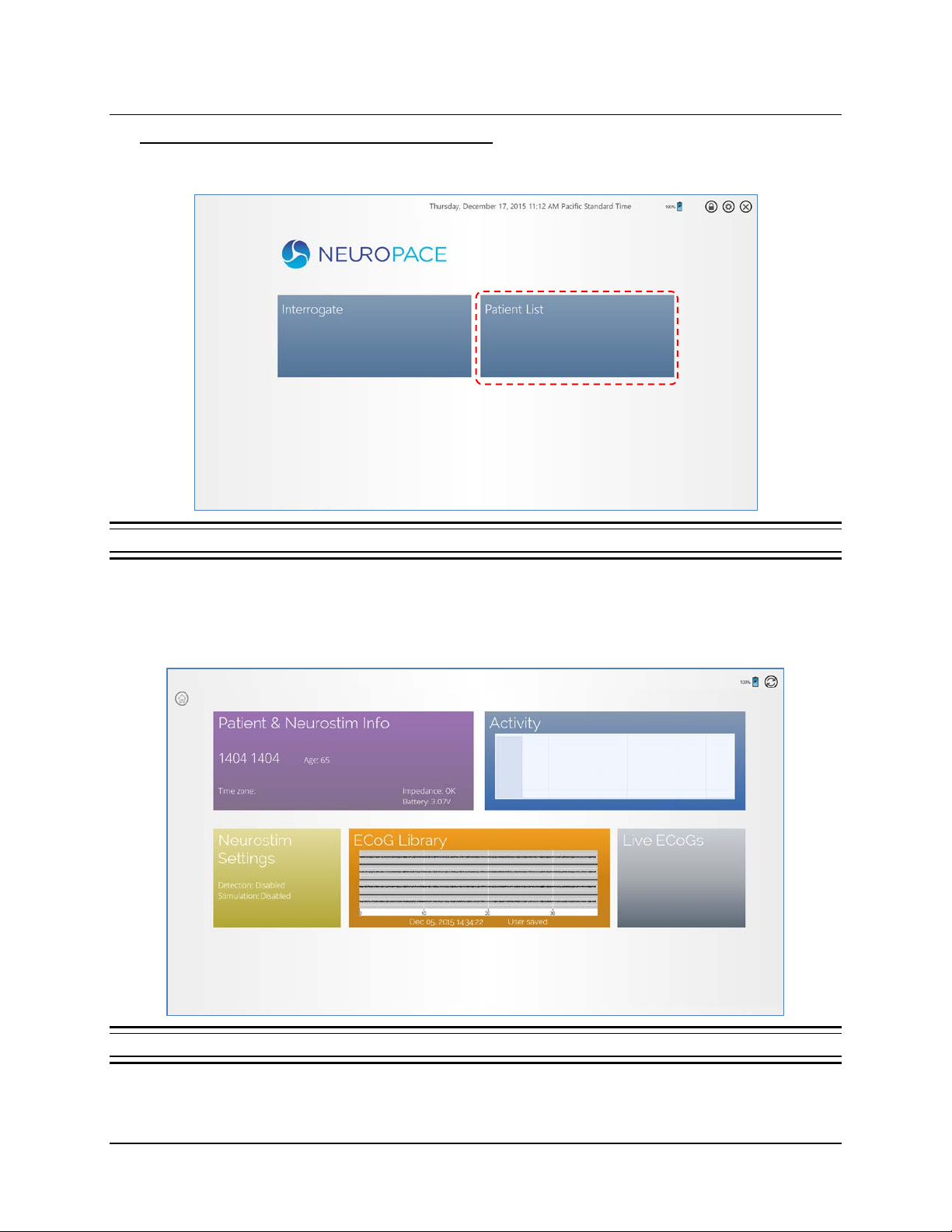
Tablet Instructions 66
Steps to Download a Detection Set to the Tablet
To download a detection set and save it locally to the tablet for offline use, follow these steps:
Figure 47 Start screen
1. Select the PATIENT LIST tile on the tablet Start screen. The patient list opens.
2. Select a patient from the patient list. The P
the tablet H
OME screen (shown in Figure 6 on pag e 18).
ATIENT HOME screen opens. Note this is different than
Figure 48 Patient Home screen
3. Select the Neurostim Settings tile. The NEUROSTIM SETTINGS > PATTER DETECTION screen opens.
RNS® System Programming Manual
Page 71
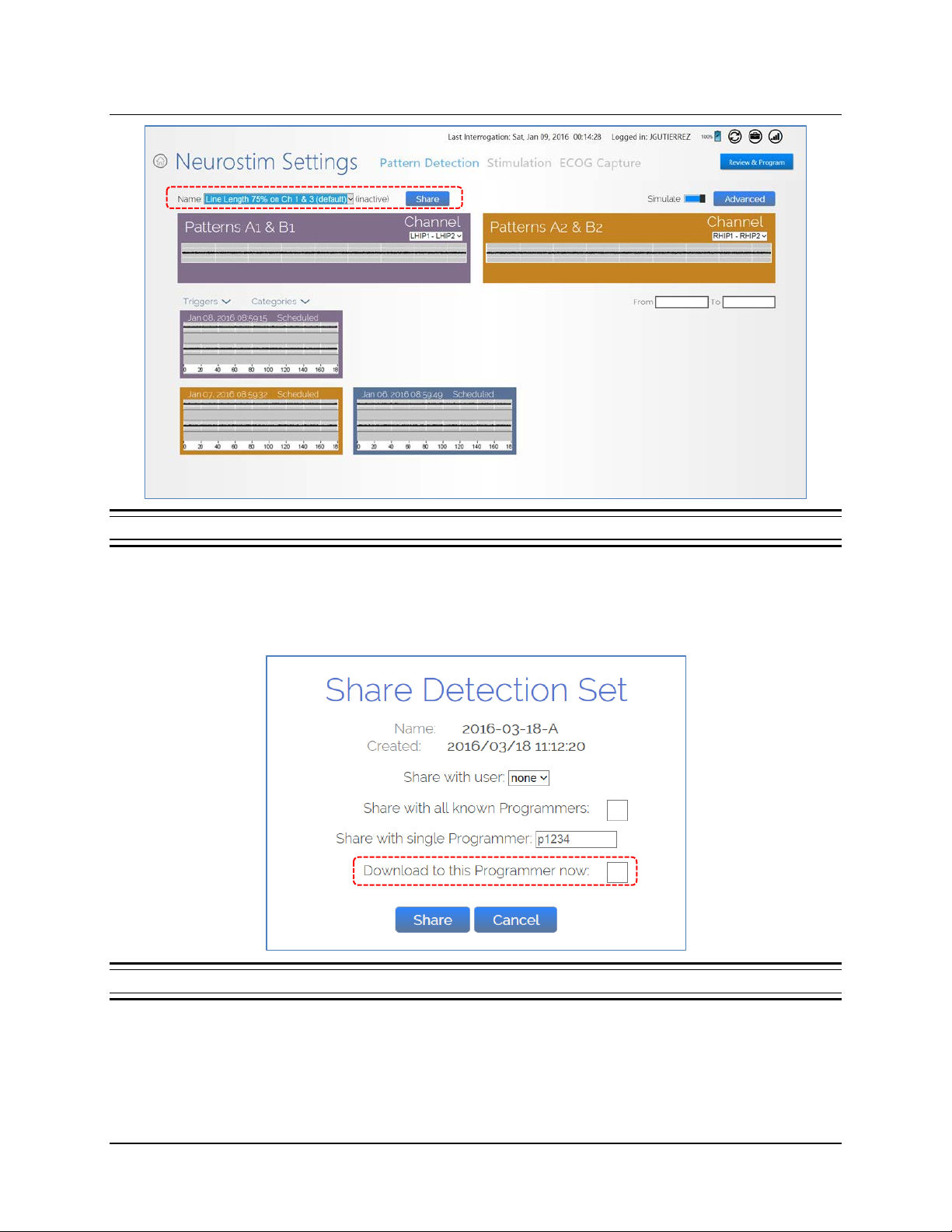
Tablet Instructions 67
Figure 49 Pattern Detection screen
4. Select the NAME field and select the name of detection set you want to download to the tablet.
5. Select the S
HARE button. The SHARE DETECTION SET dialog opens, but in this case, it includes a
checkbox named “Download to this Programmer now” along with the other sharing options.
Figure 50 The SHARE DETECTION SET dialog with download now option
6. Select the “Download to this Programmer now” checkbox.
RNS® System Programming Manual
Page 72
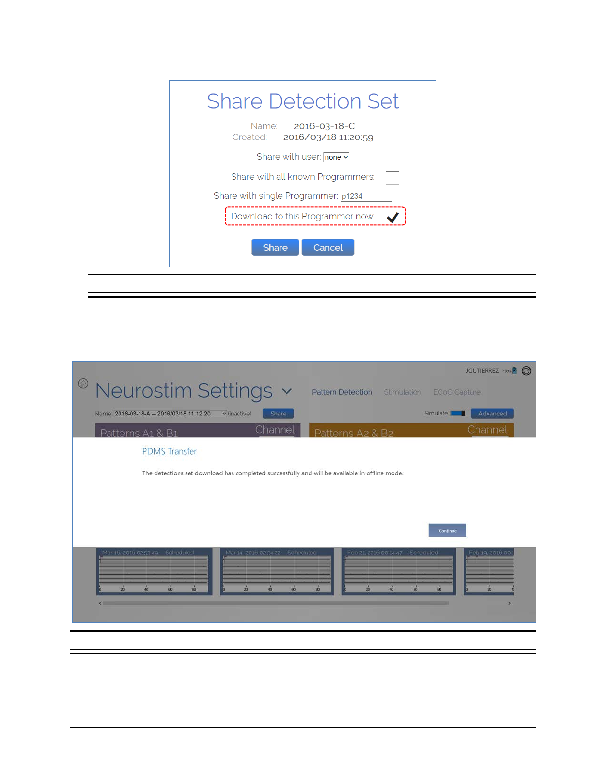
Tablet Instructions 68
Figure 51 The SHARE DETECTION SET dialog with download now option selected
7. Select the SHARE button. A download progress dialog appears briefly, and when download is
complete, a PDMS Transfer message reports “The detection set download has completed
successfully and will be available in offline mode.”
Figure 52 PDMS TRANSFER message reports a successful detection set download
RNS® System Programming Manual
Page 73
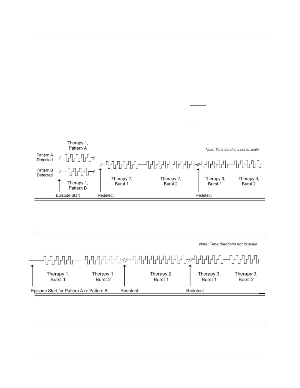
Tablet Instructions 69
OVERVIEW OF RESPONSIVE THERAPY
The RNS® Neurostimulator can deliver a therapy sequence of up to 5 individually configured therapies in
response to detected activity. The neurostimulator resumes sensing after each therapy is delivered. If the
activity is still detected, the next (sequential) therapy is delivered. If the activity is no longer detected, the
remaining therapies are not delivered and the episode ends. Therapy sequence refreshes with the
detection of each new episode.
The system enables you to configure behavior for the first therapy in therapy sequence in one of two
ways:
• You can select different bursts to be delivered in response to a specific event detector (Pattern A
or Pattern B), as depicted in Figure 53; or
• You can select up to two bursts to be delivered in response to any event det ect o r, as depicted in
Figure 54.
All subsequent therapies deliver a maximum of 2 bursts and are independent of the event detector.
Figure 53 A THERAPY SEQUENCE DELIVERED IN RESPONSE TO A SPECIFIC EVENT DETECTOR
Therapy 1 is configured to deliver a single burst in response to a specific detector. In this example, Pattern A is
detected at the episode start; Therapy Pattern A burst is delivered. If Pattern B is detected at the episode start,
Therapy Pattern B burst is delivered. Subsequent therapies, Therapy 2 and Therapy 3, are configured to deliver
2 bursts each, no matter which pattern is subsequently detected.
Figure 54 A THERAPY SEQUENCE DELIVERED IN RESPONSE TO ANY EVENT DETECTOR
Therapy 1 is configured to deliver Burst 1 and Burst 2 in response to any event detector. In subsequent
therapies, Therapy 2 is configured to deliver Burst 1 only and Therapy 3 is configured to deliver Burst 1 and
Burst 2.
RNS® System Programming Manual
Page 74
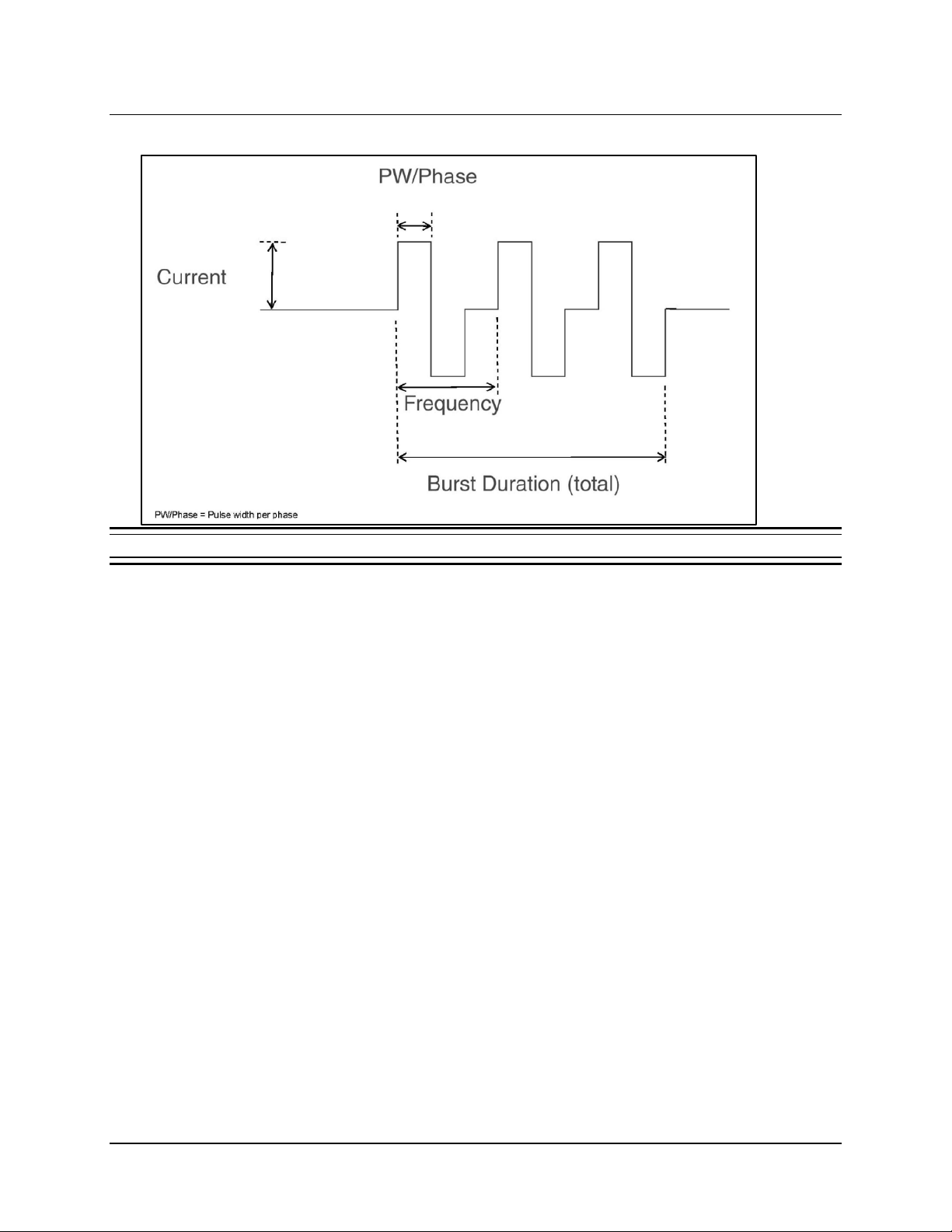
Tablet Instructions 70
The following figure identifies the parameters of a burst of stimulation therapy.
Figure 55 Parameters of a single burst of stimulation
CONFIGURE RESPONSIVE THERAPY
Detection must be enabled before responsive therapy can be enabled. Before programming responsive
therapy, at least one detector must be defined in a detection set. (If you select therapy specific to a
detection pattern, at least one detector must be defined for each pattern.) To set up a therapy sequence,
determine the number of therapies desired for delivery in response to an episode. Select each therapy
and configure each burst, which is a collection of one to many biphasic pulses.
Note: For all settings, changed settings are indicated by blue buttons, with the new setting above
and the old setting below. Gray buttons indicate settings have not changed.
Note: It is recommended to review and perform detection analysis prior to enabling responsive
therapy.
RNS® System Programming Manual
Page 75
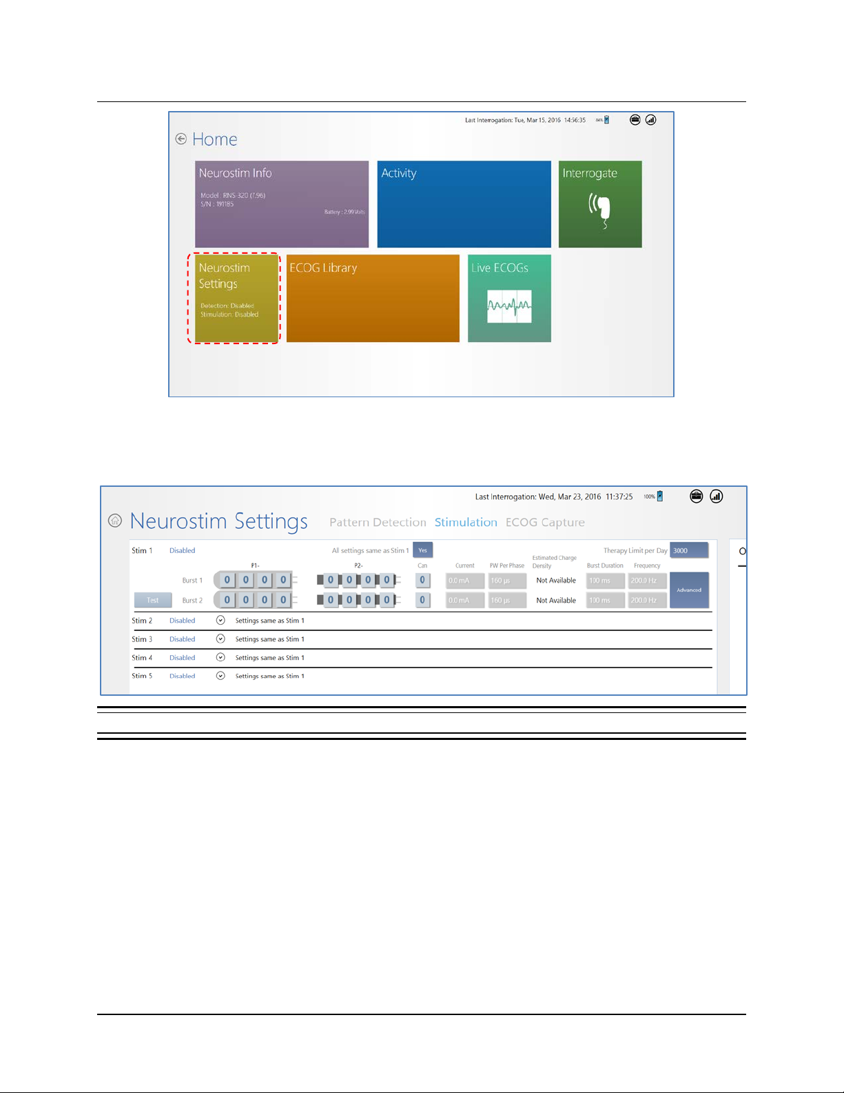
Tablet Instructions 71
1. Select N
EUROSTIM SETTINGS from the HOME screen.
2. Select S
TIMULATION at upper center of the NEUROSTIM SETTINGS screen. The STIMULATION
screen opens. (Swipe left to see the right side.)
Figure 56 Stimulation screen, left side. Swipe left to see right side.
The screen has rows STIM 1 through STIM 5 to program up to five stimulation therapies. Each
therapy is either configured or disabled. When one of the five therapies is disabled, all
successive therapies are disabled also—you cannot skip a therapy. Recall that detection
must be enabled before any therapy can be configured.
3. For each desired stimulation therapy and burst, starting with S
TIM 1 BURST 1, select the
electrodes on each lead across which to deliver therapy, by making at least one electrode
positive [+] and another negative [–]. Note that the neurostimulator can is an optional
electrode.
In general, stimulation should be delivered to the leads and electrodes from which
electrographic patterns of interest are observed. For example, if electrographic activity of
interest is observed on all channels, then the stimulation pathway should be configured to
stimulate across all electrodes. However, if electrographic activity of interest is observed on
RNS® System Programming Manual
Page 76
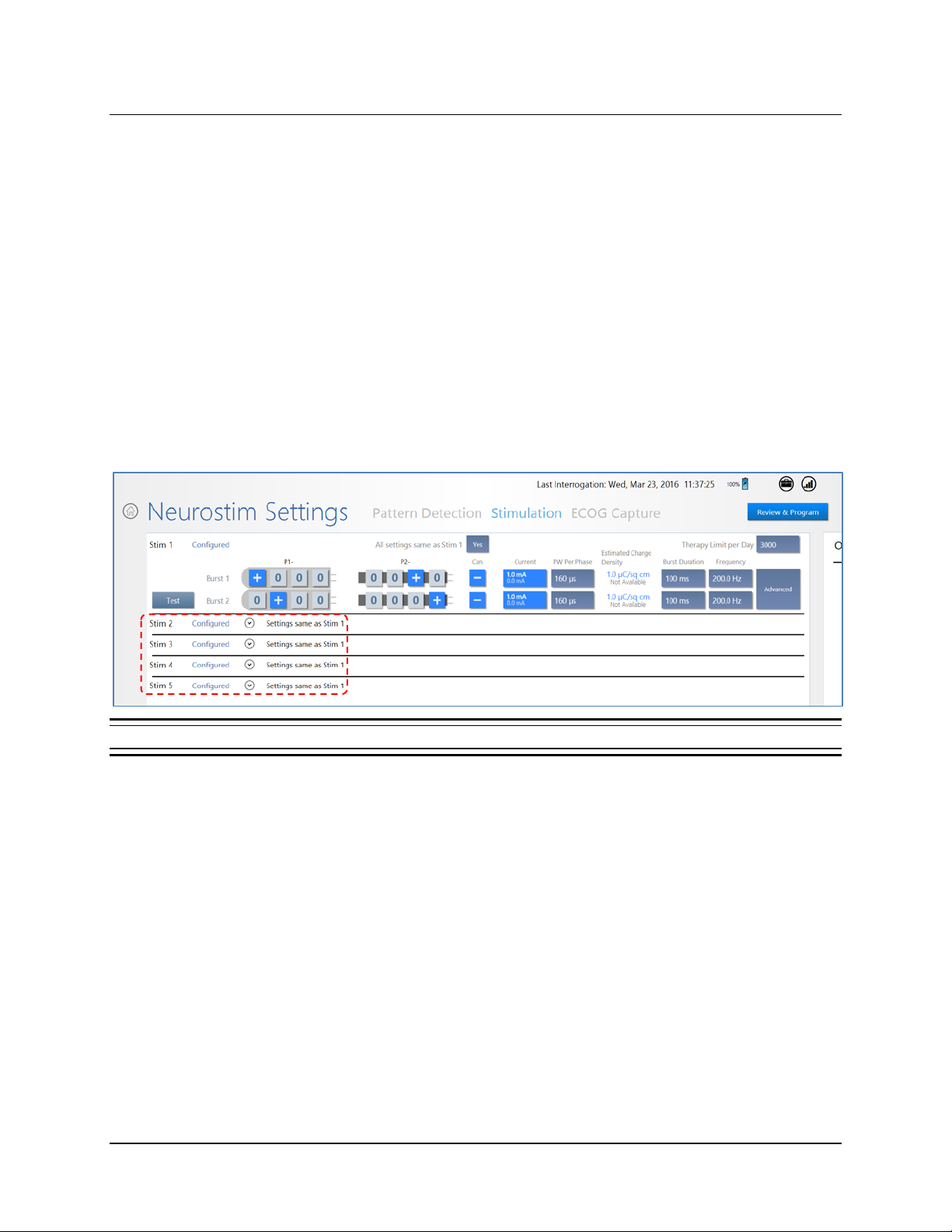
Tablet Instructions 72
only 2 channels, then the stimulation pathway should be configured such that current is
delivered through only those elec tr odes w ith electrographic activity of interest.
4. Select the level of C
5. Select the PW
URRENT to be delivered dur i ng puls es .
PER PHASE, which is the pulse width or duration (in µs) of each phase of the
biphasic current pulse.
Note: The C
C
URRENT and PW PER PHASE. The tablet limits the available choices for CURRENT and PW PER
ALCULATED CHARGE DENSITY reported on screen results from the combination of
PHASE to those which yield a CALCULATED CHARGE DENSITY less than 25 µC/sq cm.
6. Select the B
7. Select the F
URST DURATION, from 10 ms to 5000 ms.
REQUENCY of the biphasic current pulses, from 1 Hz to 333.3 Hz. Increasing
frequency decreases the time between each bip has ic puls e of curr ent, and vice v ers a.
8. If desired, apply the same settings to all five stimulation therapies. To do this, select the Y
button next to A
LL SETTINGS SAME AS STIM 1, near top center of the screen.
ES
Figure 57 Stim 1 settings copied to all therapies
RNS® System Programming Manual
Page 77
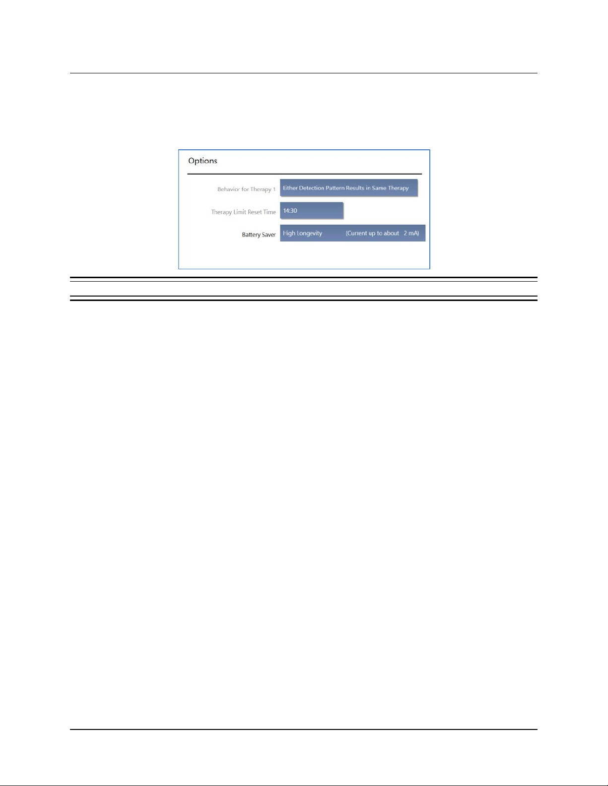
Tablet Instructions 73
9. If desired, select THERAPY LIMIT PER DAY at upper right to adjust the maximum number of
episodes the neurostimulator will treat per day.
10. If desired, swipe left to access the O
PTIONS area on the right side of the NEUROSTIM SETTINGS
screen to find the following options:
Figure 58 Options on the right side of the Stimulation settings screen
a. BEHAVIOR FOR THERAPY 1: The default is EITHER DETECTION PATTERN RESULTS IN
SAME THERAPY. Select the field to select the alternate DETECTION PATTERN SPECIFIC
THERAPY, to apply only Therapy 1 in response to detection of one specific pattern you
have programmed.
HERAPY LIMIT RESET TIME: Select the time of day (in 2 4-hour time) when the daily
b. T
therapy limit count resets to zero.
Skip to Test Stimulation Before Enabling on page 77 if you do not want to use the advanced
settings.
RNS® System Programming Manual
Page 78
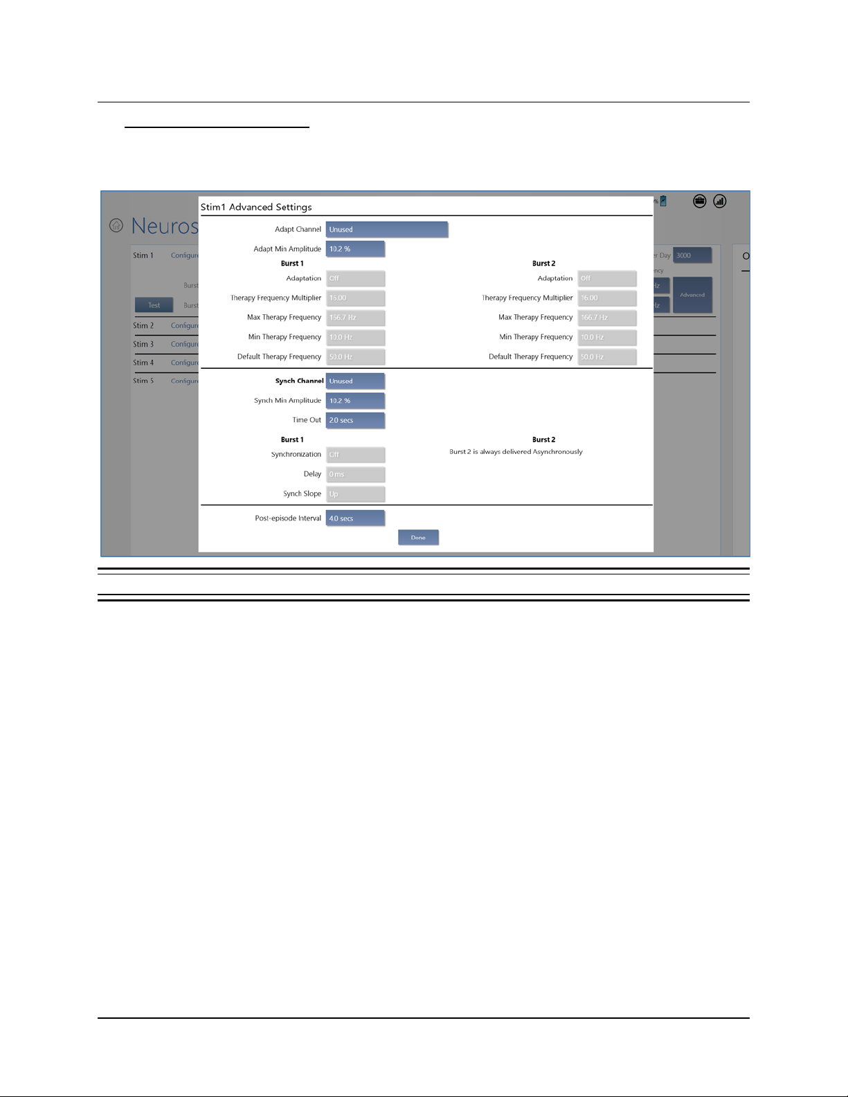
Tablet Instructions 74
Optional Advanced Settings
If desired, select ADVANCED at far right to open the ADVANCED SETTINGS screen for the selected
therapy (S
TIM row). By default, all advanced settings are disabled.
Figure 59 Stim 1 Advanced Settings
RNS® System Programming Manual
Page 79
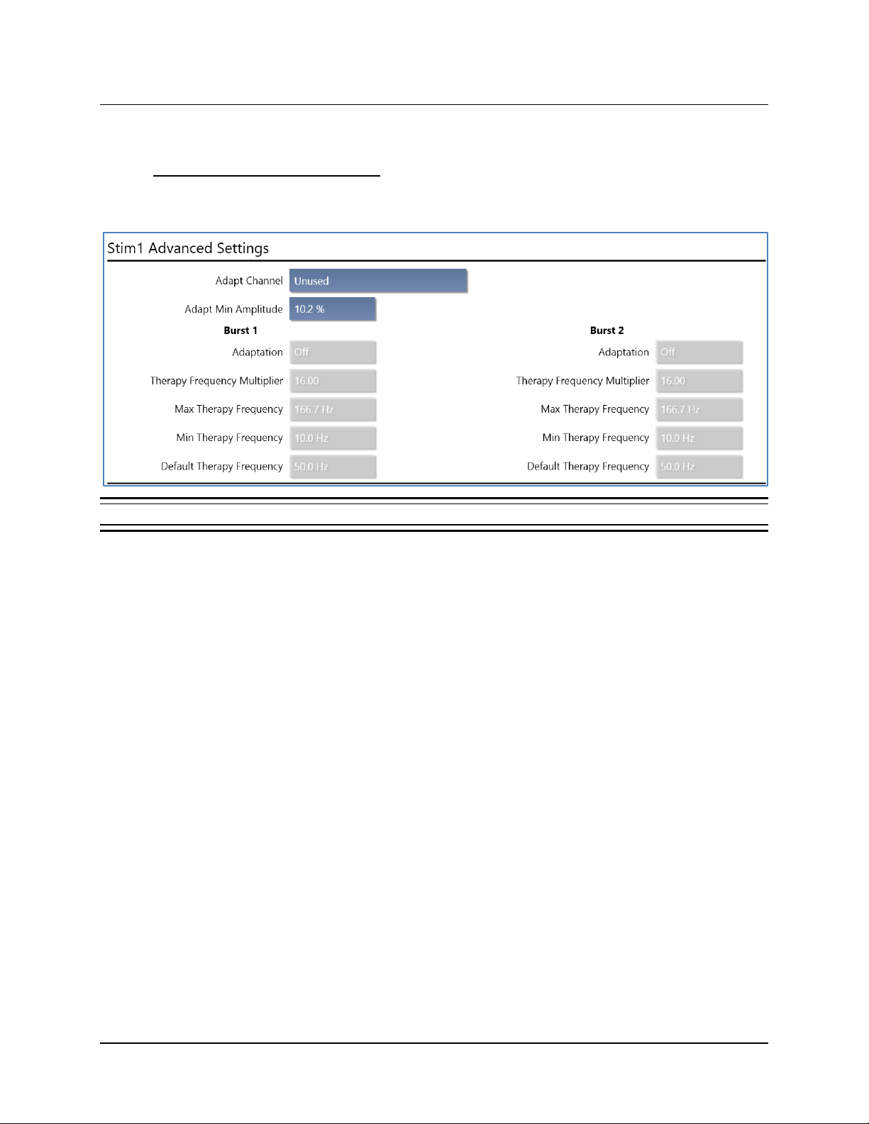
Tablet Instructions 75
The ADVANCED SETTINGS screen has upper, lower and bottom portions that let you select the
following:
Upper portion—Adaptive Therapy: Adapts the frequency and the minimum amplitude of the
stimulation therapy as a percentage of the detected signal amplitude over a chosen channel, for
one or both bursts. The available options are:
Figure 60 Adaptive therapy settings—upper portion of Advanced Settings dialog
• ADAPT CHANNEL: Select one of four channels over which to enable adaptive therapy. By
default, this is U
DAPT MIN AMPLITUDE: Select a percentage of the detected signal amplitude to be used
• A
NUSED, which means adaptive therapy is disabled.
as the minimum therapy amplitude.
Then for B
URST 1 and/or BURST 2, select settings for the following:
DAPTATION: Turn ON or OFF adaptive therapy for this burst.
• A
HERAPY FREQUENCY MULTIPLIER: A greater multiplier increases frequency of the burst.
• T
AX THERAPY FREQUENCY: Sets maximum frequency for this burst.
• M
IN THERAPY FREQUENCY: Sets minimum frequency for this burst.
• M
EFAULT THERAPY FREQUENCY: Sets default frequency for this burst.
• D
RNS® System Programming Manual
Page 80
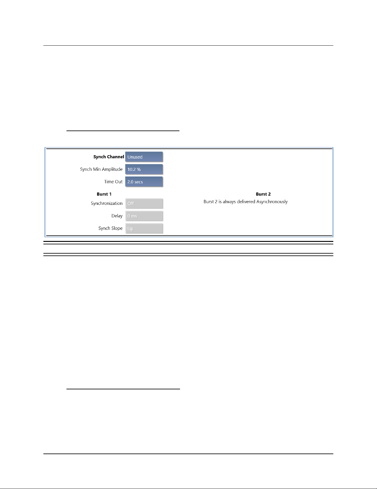
Tablet Instructions 76
Illustration: If ADAPT MIN AMPLITUDE = 100% and the detected signal frequency = 20 Hz (50
ms period), the stimulation frequency is delivered at 20 Hz (50 ms p-p interval). If
A
DAPT MIN AMPLITUDE = 50% and the sensed signal frequency = 20 Hz (50 ms
period), the stimulation frequency is delivered at 40 Hz (25 ms p-p interval).
If the neurostimulator cannot detect a stable frequency in the ECoG signal, or if
the calculated stimulation frequency is not between the M
and M
IN THERAPY FREQUENCY, then the burst is delivered at the DEFAULT THERAPY
FREQUENCY.
Lower portion—Synchronized Therapy: For BURST 1 only, synchronize delivery of therapy into
a specific part of the detected ECoG wavef orm over a chosen channel. The available options are:
AX THERAPY FREQUENCY
Figure 61 Synchronized therapy settings—lower porti on of Advanced Settings dialog
• SYNCH CHANNEL: Select one of four channels over which to deliver synchronized therapy.
YNCH MIN AMPLITUDE: Select a percentage of the detected signal amplitude to be used as
• S
the minimum amplitude for synchronized therapy.
Then for B
• S
URST 1 and/or BURST 2, select settings for the following:
YNCHRONIZATION: Turn ON or OFF synchronized therapy for BURST 1. (Burst 2 is always
delivered asynchronous l y.)
ELAY: Set the delay (in ms) for delivery of BURST 1 therapy after detection of the target
• D
ECoG waveform.
YNCH SLOPE: Select UP or DOWN.
• S
Note: If the neurostimulator is unable to synchronize therapy into a detected waveform, it reverts
to asynchronous therapy delivery after 2 seconds.
Bottom portion—Post-Episode Interval: Select the POST-EPISODE INTERVAL, from OFF (default)
to 24 HRS, to specify the time the neurostimulator waits after the end of an episode before treating
a new episode. Dur ing the post-episode interval, monitoring continues but the system will not
deliver therapy for a new episode.
RNS® System Programming Manual
Page 81
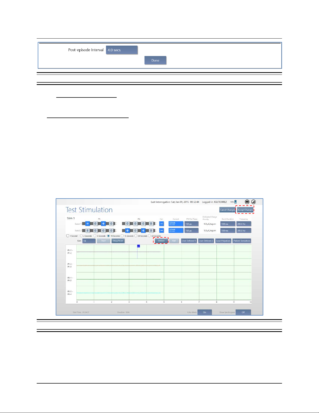
Tablet Instructions 77
Figure 62 Post-episode interval settings—bottom portion of Advanced Settings dialog
Save Advanced Settings: Select DONE to save the new advanced settings and return to the
STIMULATION screen.
Test Stimulation Before Enabling
Before enabling responsive therapy, it is important to test stimulation to make sure it is well tolerate d
by the patient and there are no undesired changes in the ECoG, such as afterdischarges.
Note: The system cannot test stimulation during a detected episode or during therapy delivery. To
test stimulation, either wait for the episode or therapy to complete, or disable detection and
therapy.
1. Select T
stimulation settings. Note that the T
EST on the far left of the row to open the TEST STIMULATION screen and test the new
EST button is not available if adaptive therapy is on (see
Optional Advanced Settings above). An ECoG is running when the screen opens. Select
D
ELIVER to deliver the test burst. Select STOP/STORE when desired to stop recording.
Figure 63 Test Stimulation screen
• You can adjust settings and retest while this screen is open. To exit test stimulation, select
A
CCEPT CHANGES or CANCEL CHANGES at upper right.
• Stimulation may evoke visual, olfactory, auditory, taste, sensory or motor responses.
RNS® System Programming Manual
Page 82
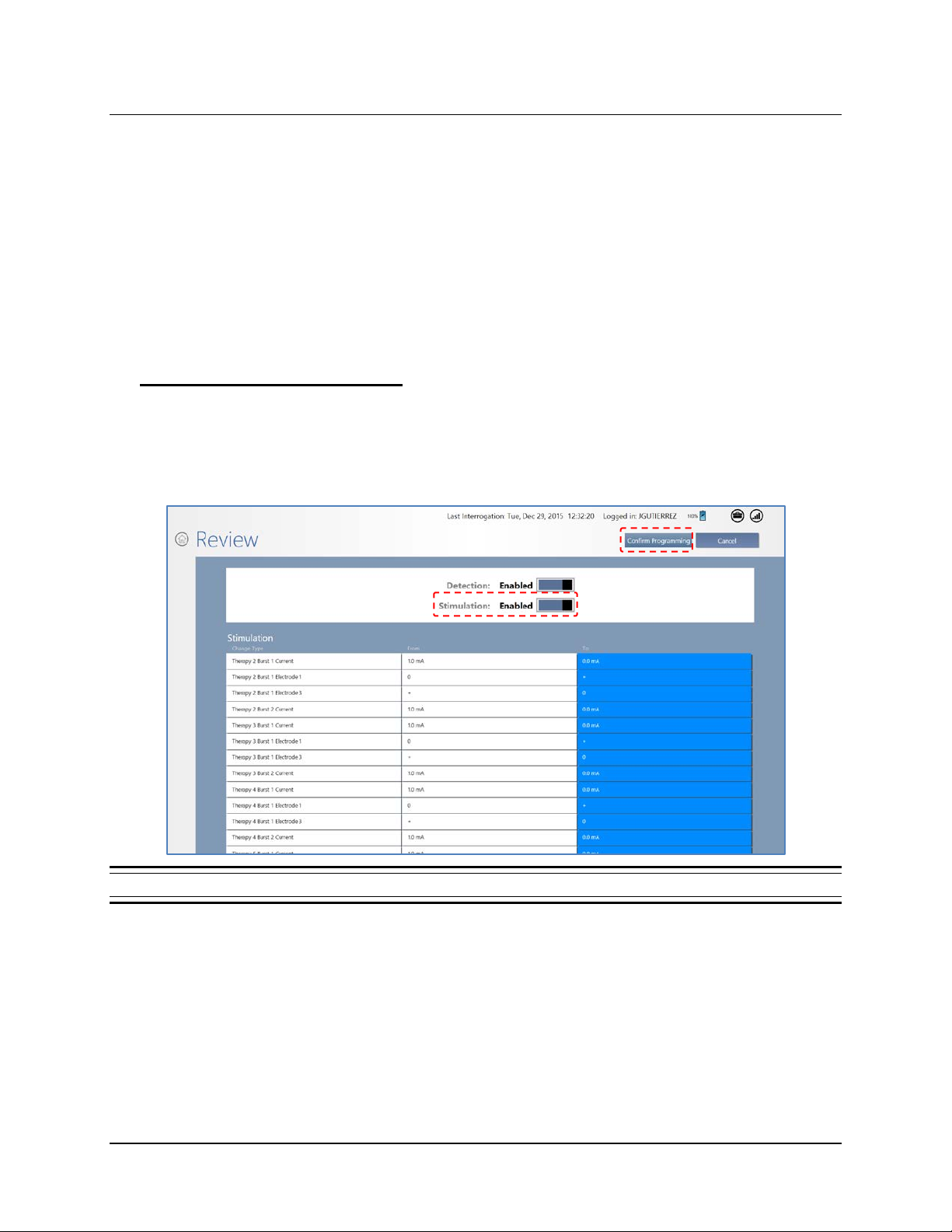
Tablet Instructions 78
• Test stimulations should be delivered to each electrode individually (electrode to
neurostimulator) to determine whether there are acute side effects from stimulation.
• Habituation to side effects resulting from stimulation has been observed; however it is not
advised to program settings that cause patient discomfort.
• Avoid stimulation settings that cause an electrographic afterdischarge.
Caution: Afterdischarge Activity
If evidence of afterdischarge activity resulting from stimulation is seen either on stored
ECoGs or during test stimulation delivery, stimulation parameters should be adjusted
to prevent such occurrence.
Enable Therapy: Review & Program
The new settings are not sent to the neurostimulator until you complete these steps.
1. Select R
EVIEW & PROGRAM at upper right. The REVIEW screen opens, showing a list of all
changed settings. If you are satisfied with the new or changed settings, proceed to the next
step. If not satisfied, select C
Figure 64 Review screen after configuring therapy. Blue items have changed.
ANCEL at upper right to return to the previous screen.
2. To activate the configured therapy, make sure STIMULATION is set to ENABLED at u pper
center.
3. On the R
within approximatel y 1 inch of the neurostimulator and select C
satisfied, select C
EVIEW screen, if you are satisfied with the new or changed settings, place the wand
ONFIRM PROGRAMMING. If not
ANCEL to return to the previous screen.
RNS® System Programming Manual
Page 83
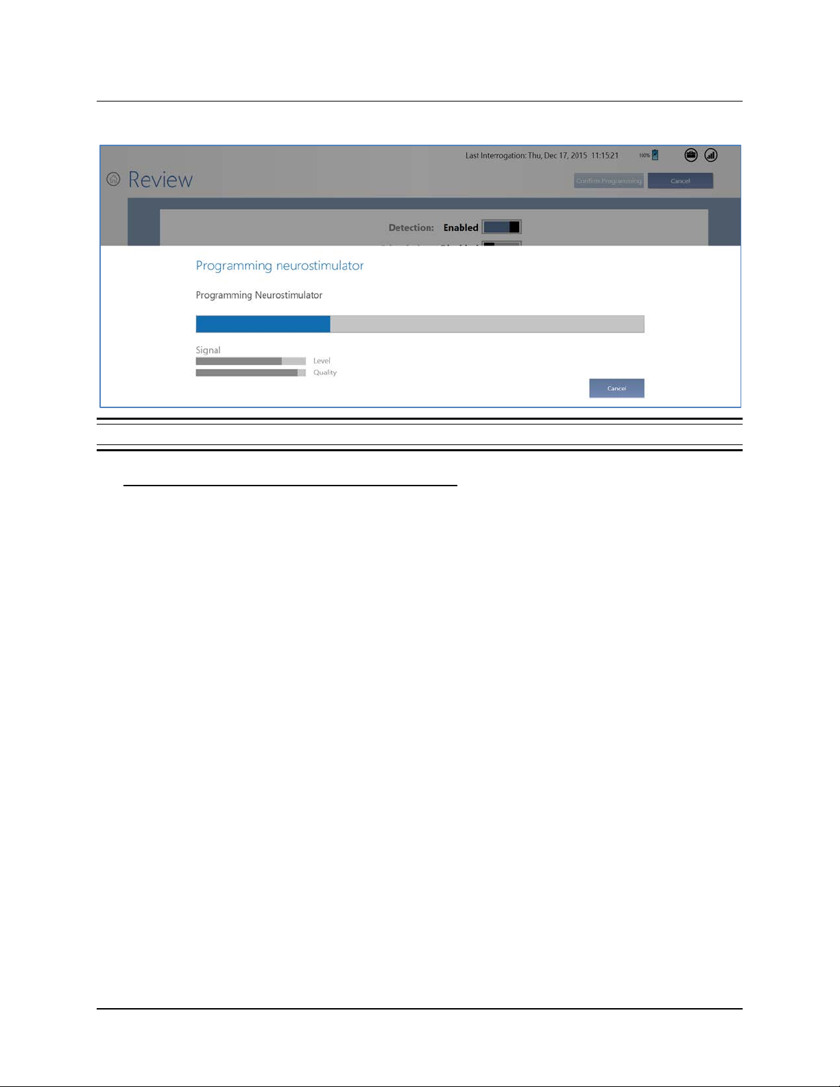
Tablet Instructions 79
The PROGRAMMING NEUROSTIMULATOR dialog shows programming progress until complete.
Figure 65 Programming neurostimulator dialog shows progress of programming
Recommended Initial Responsive Therapy Settings
Responsive stimulation therapy should be enabled once the physician has determined the
electrographic activity of interest is being detected.
• Program B
URRENT = 1.0 mA.
• C
URST 1 for electrodes on one lead and BURST 2 for electrodes on the other lead.
• Leave other parameters at their def ault values :
REQUENCY = 200 Hz
• F
• PW
• B
• Apply the same settings to all five stimulation therapies: select the Y
SETTINGS SAME AS
PER PHASE = 160 µs
URST DURATION = 100 ms
ES button next to ALL
STIM 1, near top center of the screen.
In general, stimulation should be delivered to the leads and electrodes from which electrographic
patterns of interest are observed. For example, if electrographic activity of interest is observed on all
channels, then the stimulation pathway should be configured to stimulate across all electrodes.
However, if electrographic activity of interest is observed on only 2 channels, then the stimulation
pathway should be configured such that current is delivered through only those electrodes with
electrographic activity of interest.
RNS® System Programming Manual
Page 84
Tablet Instructions 80
Recommended Therapy Modifications After Observing Clinical Response
Once the neurostimulator is programmed to provide responsive stimulation, the patient should be
seen at approximately 3-month intervals to determine whether detection and/or responsive therapy
settings should be modified. At each patient visit, the physician reviews ECoGs that are stored on the
PDMS or programmer. Detection settings should promptly detect ECoG activity and not detect on
baseline activity.
Based on the clinical response, the physician may choose to modify stimulation. If so, it is
recommended that the current amplitude be increased in 0.5 mA increments, and that new settings
be tested (see Test Stimulation Before Enabling on page 77) to ensure that it is well tolerated by
the patient and there are no undesired changes in the ECoG such as afterdischarges.
• Review data such as lead impedance, battery voltage, number of detections and stim ulations,
and stored ECoGs.
• Adjust stimulation settings if the patient reports an acute worsening or increase in clinical
seizures that is not typical.
• Consider making minor adjustments if the patient reports only a mild or no improvement in
clinical seizures.
• Allow sufficient time between stimulation adjustments to assess the patient’s clinical seizure
response.
In the RNS
therapy options (see T ab le 1). These were: pattern specific therapy (each detector triggers a different
stimulation setting); adaptive therapy (the stimulation frequency adjusts with the ECoG frequency);
synchronized stimulation (stimulation is delivered into a specific part of the ECoG waveform); and
post episode interval (responsive therapies are disabled for a specified period of time after detecting
the end of the episode). Table 1 provides the number and percentage of subjects who were treated
with any of the additional stimulation therapy options.
®
System Pivotal study very few subjects used any of the additional responsive stimulation
Table 1: Additional responsive stimulation therapy options
Number and (%) of
Subjects Programmed
Pattern Specific Therapy 29 (15%)
Adaptive Therapy 4 (2%)
Synchronized Stimulat ion 3 (2%)
Post-Episode Interval 4 (2%)
RNS® System Programming Manual
Page 85
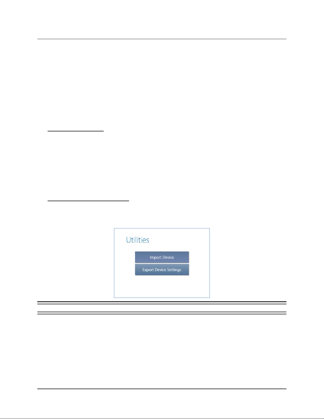
Tablet Instructions 81
EXPORT AND IMPORT DEVICE SETTINGS FOR NEUROSTIMULATOR REPLACEMENT
The tablet supports the transfer of all device settings from an old to a new neurostimulator as part of a
neurostimulator replacement procedure. With the E
you can transfer all current neurostimulator settings (recording montage, detection settings, stimulation
settings, etc.) to the new neurostim ulator .
Export and import are done directly through the tablet without using the PDMS—exported settings are
kept locally on the tablet—so no Internet connection is required. This also means that the programmer to
which the settings have been exported must be physically present with the new neurostimulator to import
settings to the new neurostimulator. This is not usually an issue because export and import are done on
the same day: before, during or after the procedure to replace the neurostimulator.
Transfer Compatibility
You can transfer settings from an RNS-300M to an RNS-300M or to an RNS-320, and you can
transfer settings between RNS-320 devices.
XPORT DEVICE SETTINGS and IMPORT DEVICE functions,
Note: S
CHEDULED IMPEDANCE is a new feature in the RNS-320. It allows you to select which
electrodes to test for impedance. Since the feature is not present in the RNS-300M, you must
select the electrodes to test (and confirm programming) on the new RNS-320 before scheduled
impedance works. Its settings are created as part of the recording montage—see Create the
Recording Montage on page 32 for instructions.
Export Neurostimulator Settings
1. Interrogate the old neurostimulator, the one from which you will transfer settings.
2. Select the U
TILITIES (toolbox) icon at upper right of the screen. The UTILITIES dialog opens.
Figure 66 Utilities dialog
3. Select EXPORT DEVICE SETTINGS. You are done. All current neurostimulator settings are stored on
the tablet ready for import.
Note: The tablet retains only the last device settings exported to it—from any neurostimulator.
Every export operation from any neurostimulator overwrites these device settings, if any.
Successfully importing and programming the settings from the tablet to a new neurostimulator
also deletes these device settings from the tablet.
RNS® System Programming Manual
Page 86
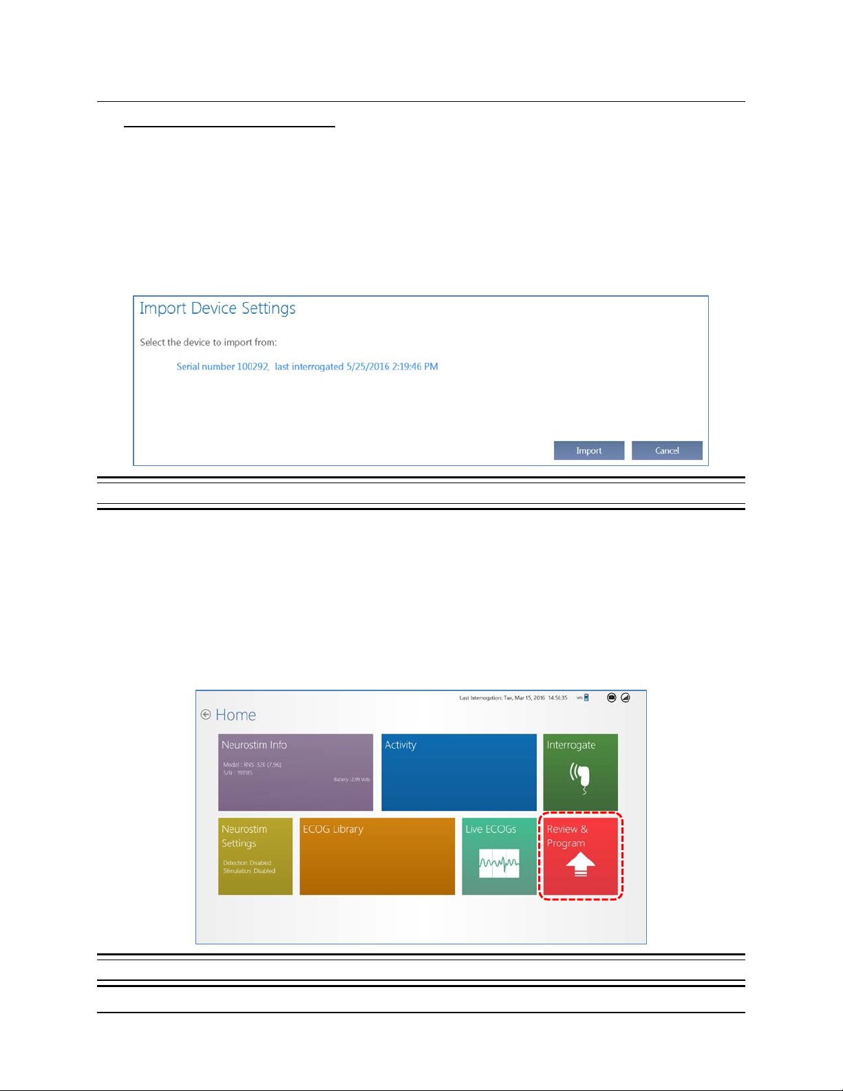
Tablet Instructions 82
Import Neurostimulator Settings
1. Interrogate the new neurostimulator, the one to which you will transfer settings .
2. Select the U
3. Select I
TILITIES (toolbox) icon at upper right. The UTILITIES dialog opens (see figure above).
MPORT DEVICE. The IMPORT DEVICE SETTINGS dialog appears. It shows the device settings
available for import by device serial number and the date and time of last interrogation before the
settings were exported to the tablet. It also notifies you if the tablet has no settings that came
from a compatible neurostimulator (for example, if you exported from an RNS-320 for use on an
RNS-300M).
Figure 67 Import Device Settings dialog
Note: Device settings can be imported only once because they are delete d from the tablet once
you successfully import and select C
below.
ONFIRM PROGRAMMING from the REVIEW screen, as desc r ibed
4. Select the device settings—the selected settings will be highlighted—and then select I
dialog notifies you that it is importing device settings.
When complete, the tablet Home screen opens. It will include a red R
EVIEW & PROGRAM tile at
lower right.
Figure 68 Home screen with the red Review & Program tile at lower right
MPORT. The
RNS® System Programming Manual
Page 87
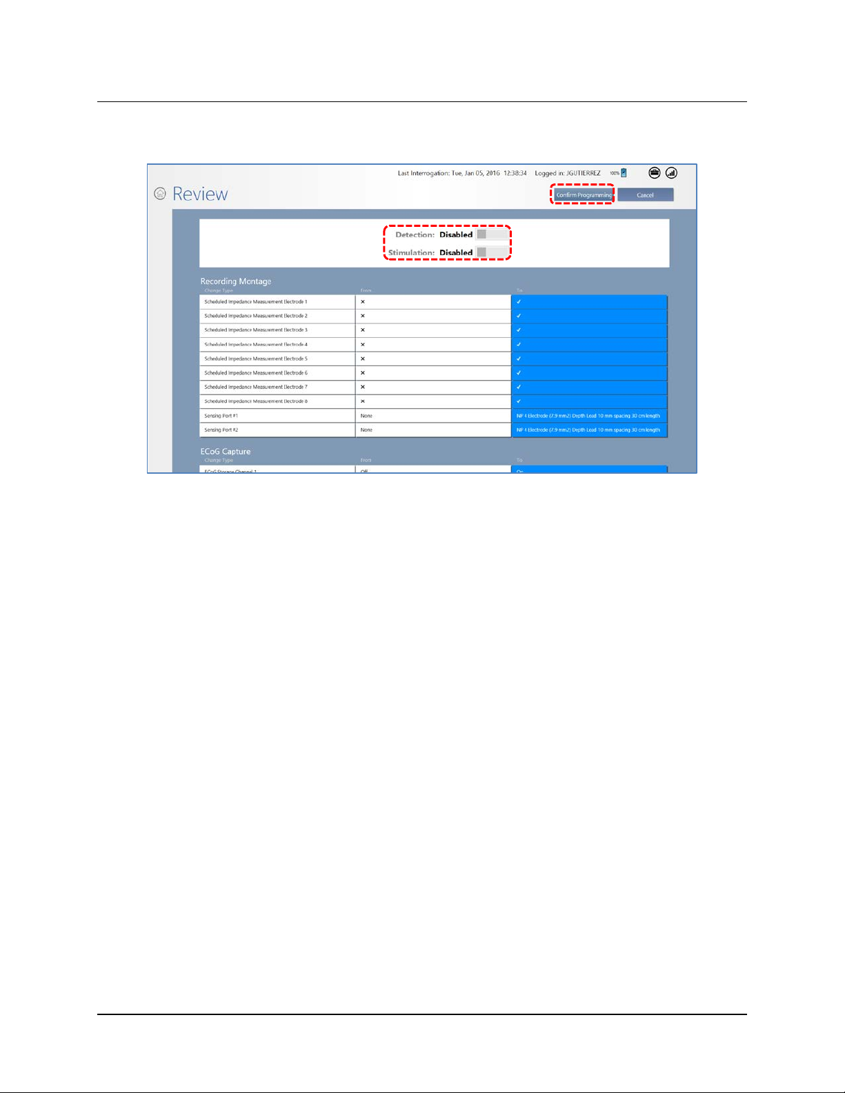
Tablet Instructions 83
5. Select REVIEW & PROGRAM. The REVIEW screen opens, showing all the settings that will be
programmed.
• If you want to enable detection and stimulation at this time, make sure D
S
TIMULATION are set to ENABLED at upper center.
ETECTION and
6. Place the wand within approximately 1 inch of the neurostimulator and select C
ONFIRM
PROGRAMMING. The PROGRAMMING NEUROSTIMULATOR dialog shows programming progress until
complete. The imported settings are deleted from the tablet when programming is complete. If
you do not complete this step, the settings will remain available on the tablet.
Note: After implanting a replacement neurostimulator, monitor the detection behavior. It may be
necessary to adjust the detection settings to ensure desired performance. If a bandpass detection
tool (R
HYTHMIC ACTIVITY or SPIKE ACTIVITY) is enabled and the settings need to be adjusted, begin
by modifying the amplitude settings. See Recommended Therapy Modifications After
Observing Clinical Response on page 80.
RNS® System Programming Manual
Page 88
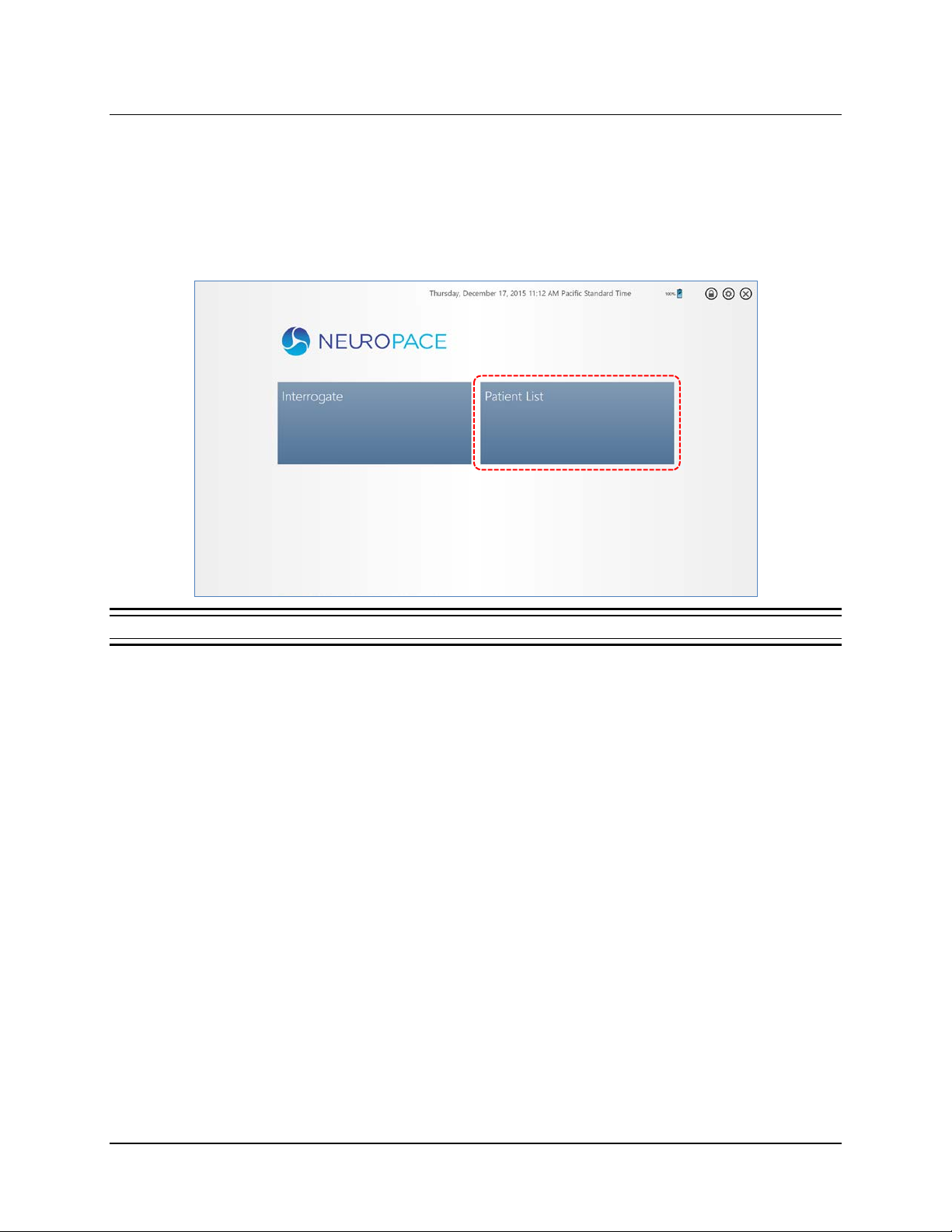
Patient List on Programmer and the PDMS on a PC 84
PATIENT LIST ON TABLET AND THE PDMS ON A PERSONAL COMPUTER
The PATIENT LIST on the tablet and the PDMS on a personal computer give access to stored data for a
selected patient. Their appearance and behavior is the same. The P
screen works only when the tablet is connected to the PDMS (through the Internet).
ATIENT LIST tile on the tablet Start
Figure 69 Tablet Start screen
Whether you select PATIENT LIST on the tablet Start screen or log in to the PDMS on a personal computer,
the information is displayed in a similar way, and on the same-named screens, as when you start an
interactive programming session by interrogating the neurostimulator. When you select P
the tablet, the differenc e is that you are not inter actin g w ith a neurostimulator; you are only accessing
stored neurostimulator information like detection and stimulation settings, and stored activity reports.
ATIENT LIST on
RNS® System Programming Manual
Page 89
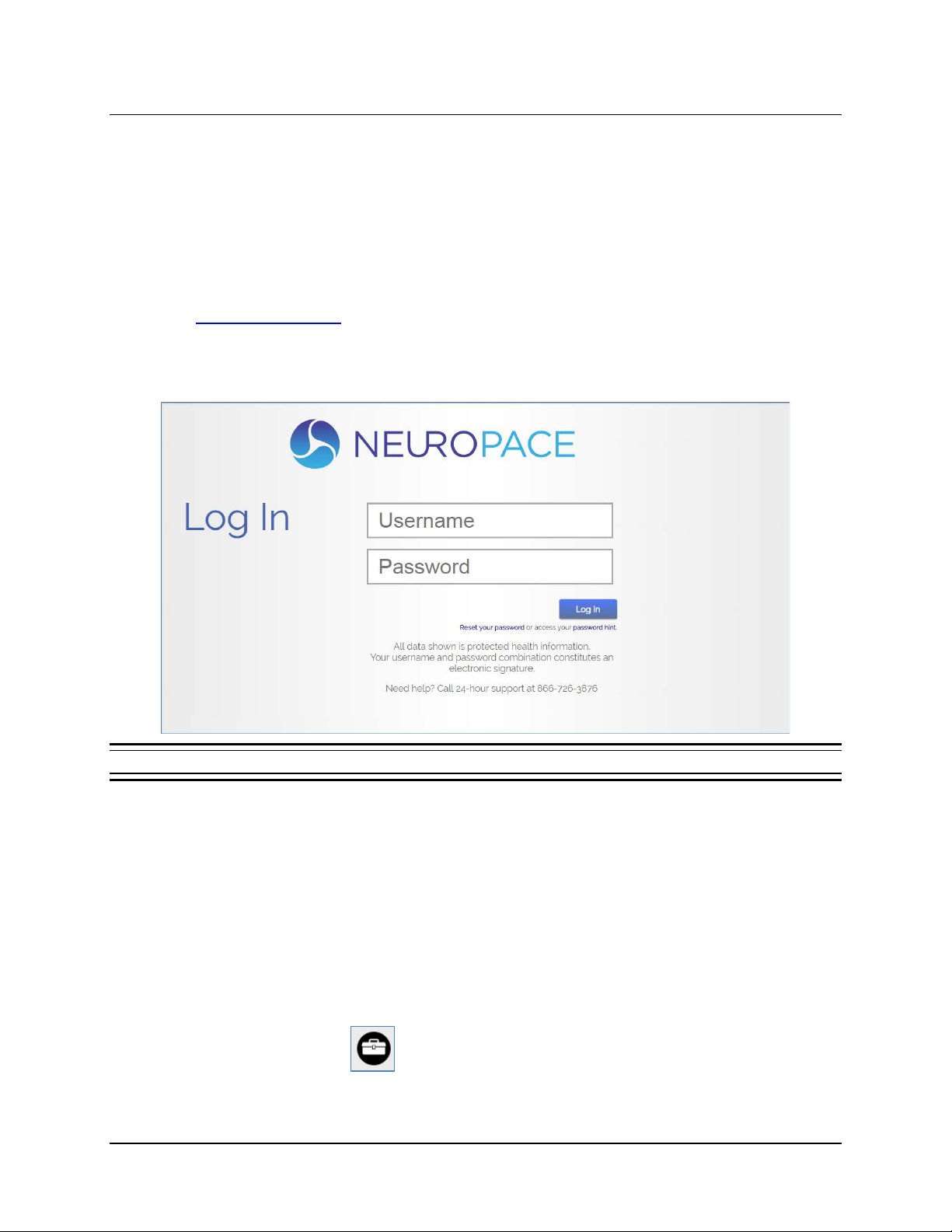
Patient List on Programmer and the PDMS on a PC 85
PDMS ACCESS ON A PERSONAL COMPUTER
Access to the secure PDMS database on a personal computer requires a username and password. If
NeuroPace has not already provided these to you, contact NeuroPace to obtain a username and
temporary password. You are responsible for maintaining the confidentiality of your username and
password.
Note: The PDMS requires you to change your password after logging in for the first time.
1. Using any computer with Internet access, open a web browser and select the PDMS link on
www.neuropace.com
2. Enter your USERNAME and PASSWORD.
3. Click L
Figure 70 PDMS Login on a personal computer
OG IN.
Note: If you have forgotten your password select RESET YOUR PASSWORD OR ACCESS YOUR
PASSWORD HINT
. The password hint you entered will be sent to the email address listed in your
profile.
The P
ATIENT LIST opens immediately when you log in to the PDMS using a web browser, just as when
you select the P
ATIENT LIST tile on the tablet. Follow the continuing instructions below to access
PDMS functions, which apply both on the tablet and on a personal computer.
PDMS PROFILE AND SETTINGS
The toolbox icon at upper right of every screen gives access to view and change your:
• Profile
• Password
• Time Zone
RNS® System Programming Manual
Page 90
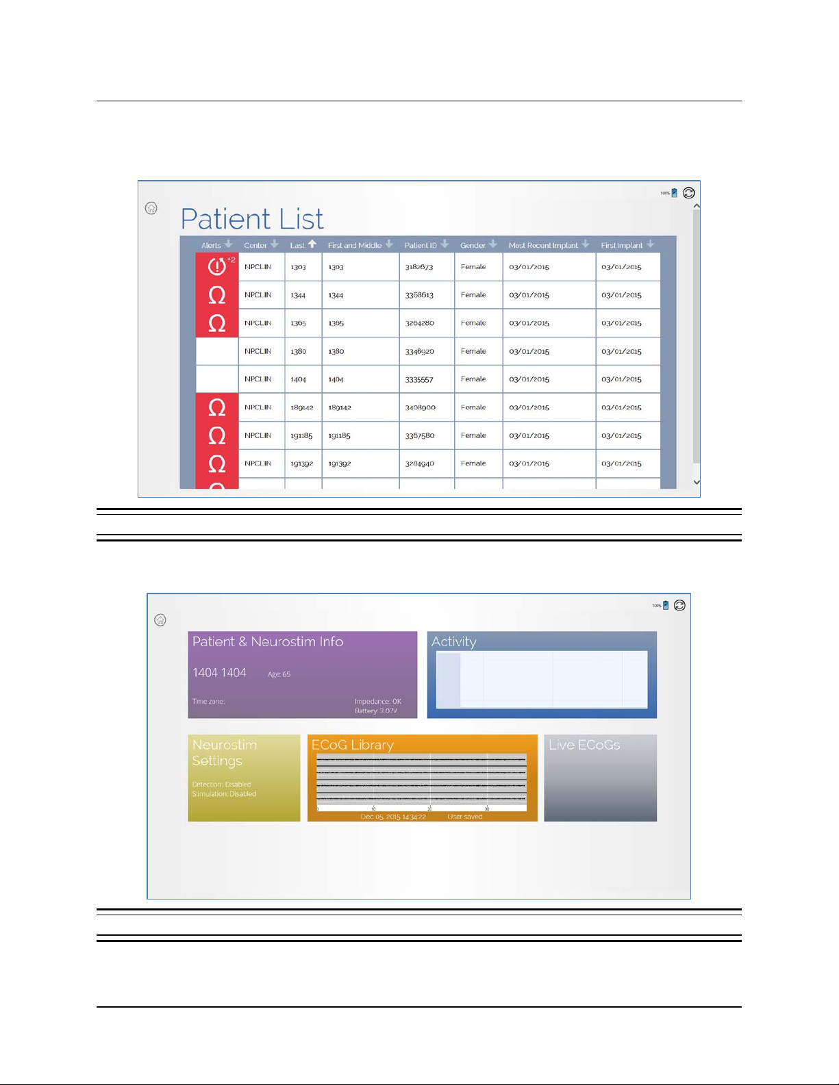
Patient List on Programmer and the PDMS on a PC 86
1. To reach the PATIENT LIST on the tablet, select PATIENT LIST from the Start screen. The
P
ATIENT LIST screen opens. When you log in to the PDMS via a web browser, it opens
directly on the P
ATIENT LIST screen.
Figure 71 Patient List screen
2. Select a patient from the PATIENT LIST. The PATIENT HOME screen opens.
Figure 72 Patient Home screen
RNS® System Programming Manual
Page 91
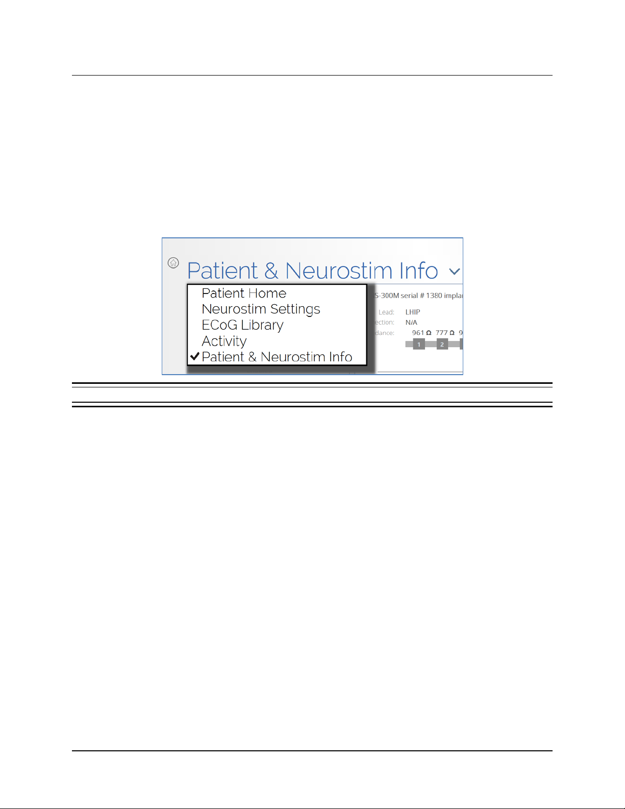
Patient List on Programmer and the PDMS on a PC 87
3. Select a tile to view its associated data for this patient.
ATIENT & NEUROSTIM INFO
• P
EUROSTIM SETTINGS
• N
CTIVITY
• A
• EC
• L
OG LIBRARY
IVE ECOGS
You can switch between patient views or return to the P
screen title at upper left (or the down arrow next to it).
Figure 73 Select to switch between patient views
The following sections provide details about each view.
ATIENT HOME screen by touching the
RNS® System Programming Manual
Page 92
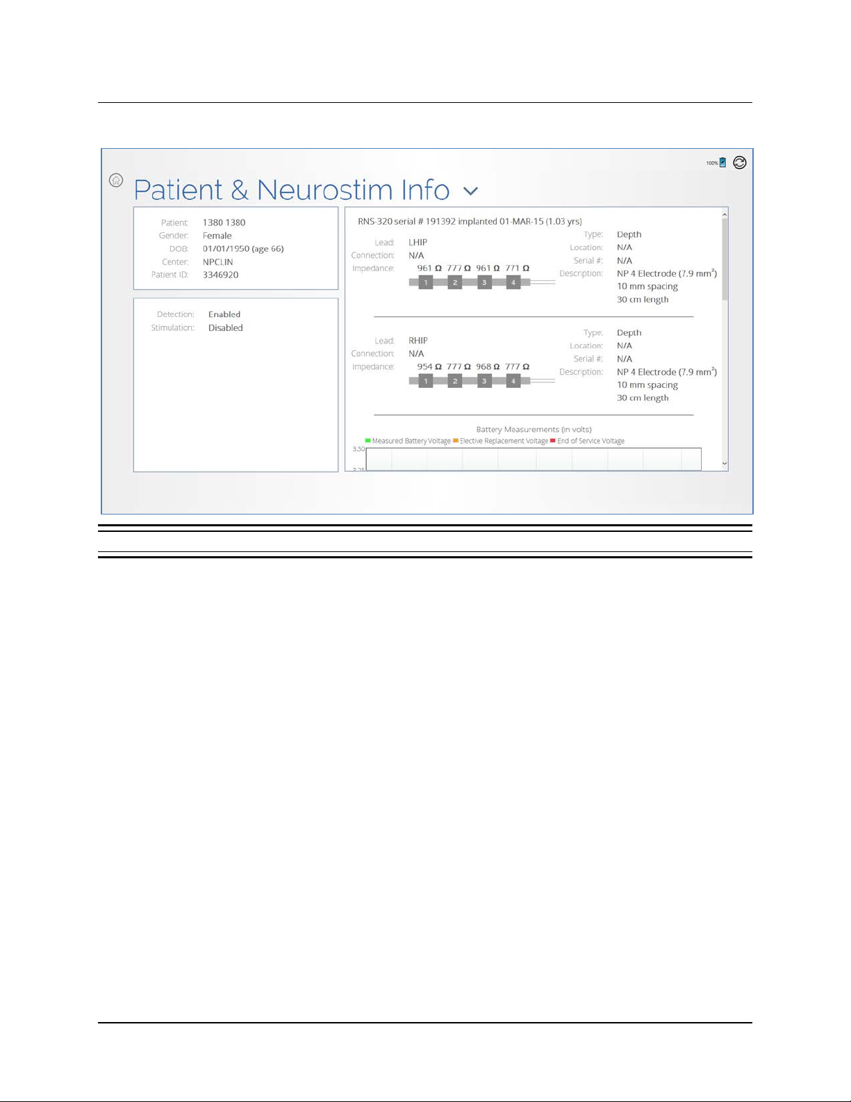
Patient List on Programmer and the PDMS on a PC 88
PATIENT & NEUROSTIM INFO
Figure 74 Patient & Neurostim Info screen
This screen provides:
• At upper left, patient information.
• At lower left, whether D
ETECTION and STIMULATION are ENABLED or DISABLED.
• At upper right, information about the neurostimulator (serial number, implant date), leads, and
electrodes.
• At lower right (swipe up to see), graphs of battery and impedance measurements over time.
NEUROSTIM SETTINGS
• This NEUROSTIM SETTINGS screen gives access to the PATTERN DETECTION, STIMULATION and
EC
OG CAPTURE screens. These have the same names as found through the NEUROSTIM
SETTINGS screen after you interrogate the neurostimulator. Here are the similarities and
differences:
ATTERN DETECTION screen: It looks exactly the same as seen in Figure 32 Pattern
• P
Detection screen (page 48). It behaves the same in that you can define, modify, and save
pattern detection settings for the current patient, with one difference: you cannot program the
new settings immediately. You can program the settings later when the programmer is in
communication with the patient’s neurostimulator (after interrogation). For instructions to use
this screen, see Configure Pattern Detection: Define and Modify Detection Settings
(page 44), starting with Phase 2: Define a Pattern Detection Set (page 48).
RNS® System Programming Manual
Page 93
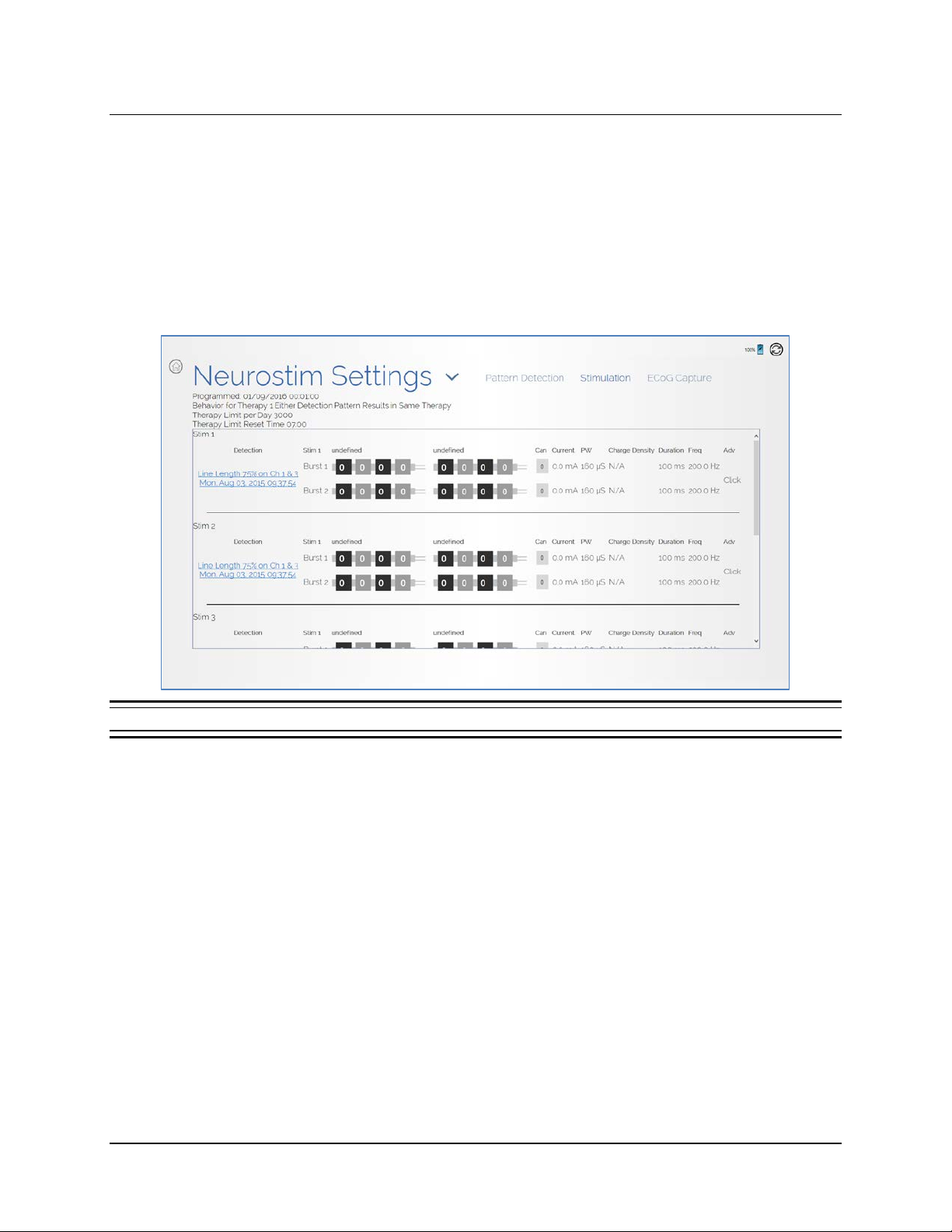
Patient List on Programmer and the PDMS on a PC 89
• When accessing the PDMS via a web browser (not via the tablet), you can define or edit
and save a detection set to the PDMS, and later download the detection set to the
programmer. Having saved a detection set to the programmer, you can program the
neurostimulator while the programmer is offline, as is required, for example, if an
operating room lacks network connectivity. Note that these instructions apply whether the
target programmer is a model PGM-300 (laptop) or model 5000 (RNS
TIMULATION screen: This screen enables you only to review the patient’s history of
• S
stimulation settings. You can adjust stimulation settings only using the tablet during an
interactive programming session. See Configure Responsive Therapy on page 70.
®
Tablet).
Figure 75 Stimulation screen through the patient list—review settings history only
RNS® System Programming Manual
Page 94
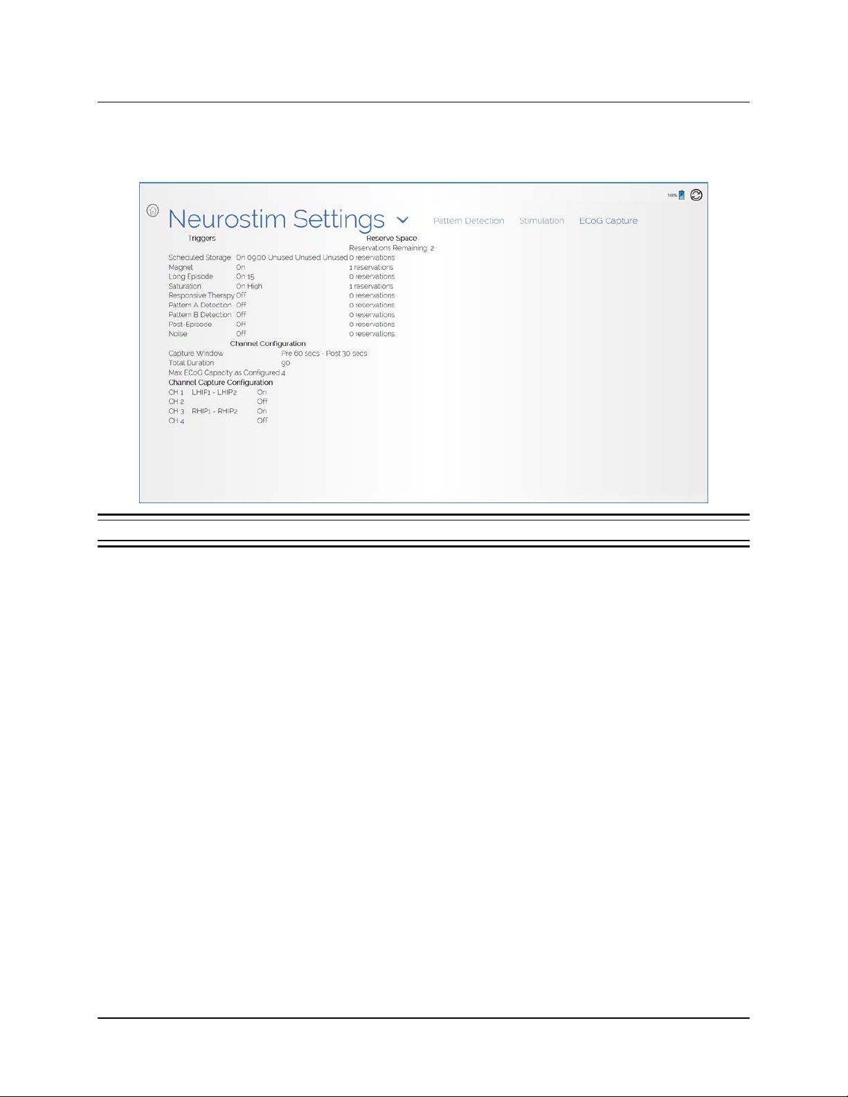
Patient List on Programmer and the PDMS on a PC 90
• ECOG CAPTURE screen: This screen reports the current capture settings. You cannot adjust
them here. You can adjust ECoG capture settings only using the tablet during an interactive
programming session. See Set up ECoG Capture on page 38.
Figure 76 ECoG Capture screen through the patient list—review current settings only
ACTIVITY
The ACTIVITY screen is a reporting screen only. It looks and behaves as shown and explained under
Activity Screen starting on page 23.
ECOG LIBRARY
The ECOG LIBRARY screen is a reporting screen only. It looks and behaves as shown and explained
under ECoG Library Screen starting on page 29.
LIVE ECOGS
The Live ECoGs tile is inactive through the patient list and the PDMS via the Internet. It can be active
only on the tablet, provided it is in communication with a neurostimulator, as described under Live
ECoGs Screen starting on page 31.
RNS® System Programming Manual
Page 95

Patient Follow-Up Activities 91
PATIENT FOLLOW-UP ACTIVITIES
The following activities are recommended at a follow-up visit:
®
• Interrogate the RNS
• Review measured batter y voltage and el ec trode impedance on the Neurostim Info Screen—
see page 20. These are measured routinely during interrogation.
Note: Battery voltage and electrode impedance are measured during interrogation. If these two
values were not measured (e.g., because therapy was being delivered), measure them manually
using the applicable M
• Review stored ECoGs on the ECoG Library Screen—see page 29—to review and consider
adjustments to:
• ECoG capture settings—see Set up ECoG Capture on page 38
• Detection settings—see Configure Pattern Detection: Define and Modify Detection
Settings on page 44
• Responsive therapy settings—see Configure Responsive Therapy on page 70
Note: You must be connected to the PDMS via the Internet to review stored ECoGs,
neurostimulator activity and all other neurostimulator information in a patient’s history. See
Connect and Login Overview on page 10.
Neurostimulator. See Interrogate the RNS® Neurostimulator on page 16.
EASURE button on the NEUROSTIM INFO screen.
• View live ECoGs—see Live ECoGs Screen on page 31.
• If you adjust detection settings, review the simulated detection on an ensemble of stored ECoGs
before programming. See Phase 2: Define a Pattern Detection Set on page 48 or Phase 3:
Customize Pattern Detection on page 52.
• If you adjust stimulation settings, test the patient’s tolerance for the new settings before
programming. See Test Stimulation Before Enabling on page 77.
• If you change any settings, remember to program the new settings into the neurostimulator, as
described in each applicable section.
Caution: Afterdischarge Activity
If evidence of afterdischarge activity resulting from stimulation is seen either on stored
ECoGs or during test stimulation delivery, stimulation parameters should be adjusted
to prevent such occurrence.
RNS® System Programming Manual
Page 96

Troubleshooting 92
TROUBLESHOOTING
Note: This section addresses only problems specific to the RNS® Tablet. For troubleshooting
information regarding other components of the RNS
troubleshooting informat ion regard ing the Neur o Pac e
®
System, see the RNS® System manual. For
®
Remote Monitor, see the NeuroPace®
Remote Monitor Manual.
If the information in this section does not resolve the problem, contact NeuroPace for further
assistance (see Contacting NeuroPace on page 4).
Network Connectivity Problems
For an overview and step-by-step instructions to establish full network connectivity with the tablet, see
Connect and Login Overview on page 10 and following.
If you are already logged in to the tablet and have lost network connectivity, first log off to return to
the login screen: return to the Start screen (see Figure 3 Start screen on page 15) and touch the
circle-X (exit) button at upper right, and then select E
XIT on the PROGRAMMER EXIT dialog. Follow the
instructions under Connect to the Internet for PDMS Access on page 10 to establish a connection.
• If a PDMS screen appears to get “stuck” or is not responding, select the R
EFRESH button at
upper right.
Note: If you attempt to connect to a Wi-Fi network that requires you to go to an Internet website to
log in, as in some hotels and coffee shops, you will not be able to log in because the tablet does
not have an Internet browser program. As a medical device, its Internet connectivity is restricted
to the PDMS only.
Abnormal Lead Impedance (greater than 3500 Ohms or less than 250 Ohms)
Troubleshooting During an Intraoperative Procedure
The goal of the following procedures is to ascertain if the abnormal lead impedance measurement is
associated with the lead or with the RNS
®
Neurostimulator port to which the le ad i s connec ted .
1. Repeat the impedance measurements.
2. If the impedance remains abnormal, note the electrode label ass ociate d w ith the a bnormal
impedance
3. Reconnect leads in the same neurostimulator port.
• Disconnect and reconnect the leads to the connector cover and neurostimulator
according to the instructions in the relevant section of the system manual.
• View the live ECoGs to verify that the signal is sufficient and without noise or artifacts.
• Repeat impedance measurements.
4. If the impedance remains abnormal, note the electrode label associated with the abnormal
impedance.
5. Place leads in the opposite neurostimulator port.
RNS® System Programming Manual
Page 97

Troubleshooting 93
• Disconnect leads, place leads in the opposite connector cover ports, and reconnect the
connector cover and neurostimulator according to the instructions in the relevant section
of the system manual.
• Program the new lead information and montage and use the same electrode labels for
the new lead configuration.
• View the live ECoGs to verify that the signal is sufficient and without noise or artifacts.
• Repeat impedance measurements.
Note: If the abnormal impedance is associated with the same electrode label, then the problem
may be with the lead.
Depth lead - Impedance > 3500 Ohms
• The depth lead may be damaged and should be replaced. Refer to instructions in the
relevant section of the system manual.
Depth lead - Impedance < 250 Ohms
• The depth lead may be damaged and should be replaced. Refer to the instructions in the
relevant section of the system manual.
Cortical strip lead - Impedance > 3500 Ohms
• The high impedance may be due to air.
• Irrigate the area around the cortical strip lead and examine the geometry.
• Repeat impedance measurements.
• If the impedance remains abnormal, the cortical strip lead may be damaged and should
be replaced. Refer to the instructions in the relevant section of the system manual.
Cortical strip lead - Impedance < 250 Ohms
• The cortical strip lead may be damaged and should be replaced. Refer to the instructions
in the relevant section of the system manual.
Note: If the abnormal impedance is not associated with the same electrode label, the problem
may be with the neurostimulator or connector cover.
6. Replace the connector cover.
• Disconnect the leads from the connector cover and reconnect the leads to a new
connector cover. Connect to the neurostimulator and troubleshoot according to the
instructions in the relevant section of the system manual.
• View the live ECoGs to verify that the signal is sufficient and without noise or artifacts.
• Repeat impedance measurements.
7. If the impedance remains abnormal, replace the neurostimulator. Refer to instructions in the
relevant section of the system manual.
RNS® System Programming Manual
Page 98

Troubleshooting 94
Troubleshooting During a Routine Follow-up
1. Repeat lead impedance measurements to verify abnormal lead impedance.
2. Take an image (X-ray or CT scan) of the implanted lead(s) and connector cover to discern
the integrity of the lead.
• Lead Damage – If the lead is damaged or fractured, it is recommended to abandon and
replace the lead. Refer to the instructions in the relevant section of the system manual.
• Poor Connection – If the lead is not completely installed in the connector cover, it is
recommended to surgically revise the connection between the connector cover and
lead. Refer to the instructions in the relevant section of the system manual.
Note: It is normal for lead impedance measurements to fluctuate following the implant procedure
due to the acute injury and healing processes of the brain tissue.
Note: Lead damage may not be immediately apparent from the live ECoGs. Using the N
ECoG capture trigger may be helpful in future troubleshooting techniques.
OISE
RNS® System Programming Manual
Page 99
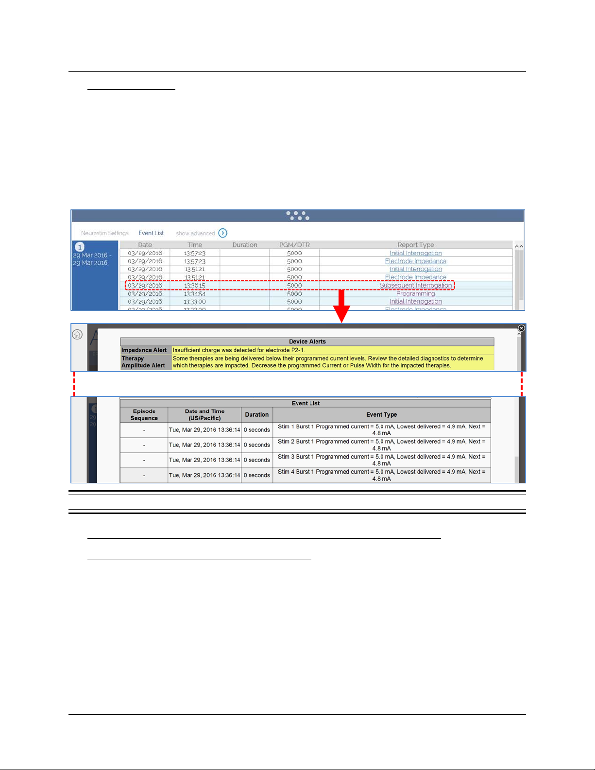
Troubleshooting 95
Insufficient Charge
Insufficient charge occurs when the neurostimulator is unable to fully deliver the programmed
therapy. It may be due to high lead impedance or the neurostimulator configuration settings. If you
receive an insufficient charge alert (see Figure 9 and Figure 10 on page 22) that cannot be
explained by observed lead impedance changes, or if the first entries in the PDMS interrogation
report event list show the “Programmed current” is higher than the “Lowest delivered” current, contact
your NeuroPace Field Clinical Engineer. The NeuroPace Field Clinical Engineer will help you review
the neurostimulator configuration settings to determine the cause. An example interrogation report is
shown below in Figure 77.
Top of detailed report shows alerts
Bottom of detailed report shows specific bursts delivered below programmed current levels
Figure 77 Accessing an interrogation report that shows insufficient charge
Select to open detailed report
Noise, Artifacts, Poor Signal Displayed, or No Signal Displayed in Live ECoG
Troubleshooting During an Intraoperative Procedure
1. If no ECoG signal is seen, make sure the recording montage has been programmed.
2. If the signal is too high in amplitude or saturating, decrease the gain setting.
®
3. If the leads are positioned over the RNS
Neurostimulator, move them away from the
neurostimulator.
®
4. Remove the connector cover from the RNS
5. Flush the connector cover (with leads inserted) and the RNS
Neurostimulator using the torque driver.
®
Neurostimulator connector
area with saline.
RNS® System Programming Manual
Page 100

Troubleshooting 96
6. Remove the leads from the connector cover. Clean the proximal end of the lead with saline
and visually inspect that the lead end is free of excess blood or other tissue.
7. Reinsert the leads. Verify that they are fully inserted into the connector cover ports.
®
8. Place the connector cover back onto the RNS
leads are fully inserted in the connector cover ports.
9. Secure the connector cover onto the RNS
10. View the live ECoGs to verify that the signal is sufficient and free of noise or artifacts. Isolated
artifacts may be the result of electrostatic discharge (ESD) / static electricity shocks to the
tablet.
11. If the signal contains noise or artifacts, disconnect the AC adapter from the tablet and run on
battery power. (Make sure the battery is charged before doing so.) Disconnect the network
cable as well if it is connected.
12. If the signal is not sufficient or still contains noise or artifacts, measure the impedances. If the
impedances are out of range, follow the instructions in the relevant section of the system
manual.
13. If impedance measurements are normal, but the problem remains, try using a different tablet,
if available.
Neurostimulator. Verify, once again, that the
®
Neurostimulator using the torque driver.
14. If the problem persists, replace the neurostimulator. Refer to the relevant section of the
system manual.
Troubleshooting During a Routine Follow-up
1. Reposition the wand over the RNS® Neurostimulator and interrogate again.
2. If the signal is not sufficient, follow the Poor or No Communication Between the RNS®
Neurostimulator and the RNS® Tablet instructions in this section.
3. If the signal is not sufficient, measure the impedances. If the impedances are out of range,
follow the instructions in the relevant section of the system manual.
Poor or No Communication Between the RNS® Neurostimulator and the RNS® Tablet
1. Confirm that the wand cable is inserted securely into the USB port on the tablet.
2. Confirm that the concave side of the wand faces the neurostimulator and that the wand is
within approximatel y 1 inch of the neurostimulator.
3. Disconnect the AC adapter from the tablet and run on battery power. (Make sure the battery
is charged before doing so.) Disconnect the network cable as well if it is connected.
4. Move electronic equipment that may be a source of interference or move away from such
equipment if possible. (Turning electronic equipment on and off may help identify the source
of any interference.)
• Reposition the wand over the neurostimulator and interrogate.
• View the live ECoGs to verify that the signal is sufficient and void of noise or artifacts.
5. Restart (turn OFF and back ON) the tablet. Attempt the interrogation again.
6. Try a different tablet, if available.
RNS® System Programming Manual
 Loading...