


SERIES 180 (KM 183 / 184 / 185)
B
O M
· . · ·
() / - · - · @. · ..

1. Einleitung
In dieser Anleitung nden Sie alle wichtigen Informationen für den Betrieb und die Pege des
von Ihnen erworbenen Produkte s. Lesen Sie diese
Anleitung sorgfältig und vollständig, bevor Sie das
Gerät benutzen. Bewahren Sie sie so auf, dass sie
für alle momentanen und späteren Nutzer jederzeit
zugänglich ist.
Weitergehende Informationen, insbesondere
auch zu den verfügbaren Zubehörteilen und den
Neumann-Servicepartnern, nden Sie jederzeit auf
unserer Website www.neumann.com.
Diese Serie zeichnet sich aus durch:
• besonders niedriges Eigengeräusch und höchste Aussteuerbarkeit
• das bewährte transformatorlose „fet 100®“Schaltungskonzept
• besonders saubere, freie und verfärbungsfreie
Klangübertragung
• sehr gleichmäßige, zur 0°-Schalleinfallsrichtung parallele Frequenzkurven bei den Druckgradienten-Empfängern KM 184 und KM 185.
Damit wird der Aufnahmesektor bis ± 135°
ohne Klangfärbungen übertragen.
2. Sicherheitshinweise
Vor der Inbetriebnahme lesen Sie bitte die beigefügten Safety Guide und Quick Guide durch!
Download auch unter www.neumann.com.
Reparatur- und Servicearbeiten dürfen nur von
erfahrenem und autorisiertem Fachpersonal durchgeführt werden. Wenn Sie das Gerät eigenmächtig
önen oder umbauen, erlischt die Gewährleistung.
Verwend en Sie das Gerät nur unter den in den tec hnischen Daten angegebenen Betriebsbedingungen.
Lassen Sie das Gerät auf Raumtemperatur akklimatisieren, bevor Sie es einschalten.
Nehmen Sie das Gerät nicht in Betrieb, wenn es
beim Transport beschädigt wurde.
Verlegen Sie Kabel stets so, dass niemand darüber
stolpern kann.
Halten Sie Flüssigkeiten und elektrisch leitfähige
Gegenstände, die nicht betr iebsbedingt notwendig
sind, vom Gerät und dessen Anschlüssen fern.
Verwenden Sie zum Reinigen keine Lösungsmittel
oder aggressiven Reinigungsmittel.
Entsorgen Sie das Gerät nach den Bestimmungen
Ihres Landes.
3. Kurzbeschreibung
Der bestimmungsgemäße Gebrauch dieses Mikrofons ist die Wandlung akustischer in elektrische
Signale.
Die „Series 180“-Kondensator-Kleinmikrofone verwenden die „fet 100®“-Technik. Sie besitzen eine
transformatorlose Mikrofonschaltung und Kapseln
mit den Richtcharakteristiken Kugel (KM 183),
Niere (KM 184) und Hyperniere (KM 185).
4. Lieferumfang
• Mikrofon
• Stativgelenk SG 21 bk
• Windschutz WNS 100
5. Inbetriebnahme
Mikrofon einrichten
Befes tigen Sie das Mikro fon auf einem ausreichend
stabilen und standfesten Stativ.
Verwenden Sie ggf. eine elastische Auängung,
um die Übertragung von Körperschallgeräuschen
mechanisch zu unterdrücken.
Zur Dämpfung von Wind- oder Popgeräuschen verwenden Sie b ei Bedarf einen W ind- oder Popschutz
aus unserem Zubehörprogramm.
Mikrofon anschließen
Vorsicht: Eine falsche Versorgungsspannung
kann das Mikrofon beschädigen
Achten Sie beim Anschließen von Kabeln auf die
korrekte Verriegelung der Steckverbinder.
Vorsicht: Sehr laute Geräusche können Ihr
Gehör oder Ihre Lautsprecher schädigen!
Minimieren Sie an den angeschlossenen Wiedergabe- und Aufnahmeger äten die Lautstärke, bevor
Sie das Mikrofon anschließen.
Verbinden Sie das Mikrofon über ein geeignetes
Kabel mit dem Mikrofoneingang Ihres weiterverarbeitenden Audiogerätes.
Schalten Sie die Phantomspeisung P48 an Ihrem
Audiogerät ein.
Erhöhen Sie an den weiterverarbeitenden Geräten
schrittweise den Lautstärkepegel.Stellen Sie die
DE DE
2

Vorverstärkung (Gain) Ihres weiterverarbeitenden
Gerätes so ein, dass bei höchstem Pegel keine
Verzerrungen aureten.
Störschallunterdrückung
Der Übertragungsbereich der Mikrofone reicht
bis zu sehr tiefen Frequenzen. Entsprechend
empndlich ist das Mikrofon natürlich auch für
tieffrequente Störungen wie Körperschall oder
Wind- und Popgeräusche. Daher empehlt sich
ggf. die Verwendung einer elastischen Auängung,
eines Windschutzes und/oder eines Popschutzes.
Funktionstest
Sprechen Sie das Mikrofon einfach nur an. Anpusten oder „Anploppen“ führt zu gefährlichen
Schalldruckpegeln.
6. Außerbetriebnahme und Auewahrung
Verringern Sie vor der Außerbetriebnahme und
dem Abziehen von Kabeln den Lautstärkepegel
Ihres weiterverarbeitenden Gerätes.
Trennen Sie die Kabelverbindungen.
Ziehen Sie b eim Lösen von Kabel n stets nur an den
Steckverbindern und nicht am Kabel.
Mikrofone, die nicht im Einsatz sind, sollte man
nicht auf dem Stativ einstauben lassen. Wird ein
Mikrofon längere Zeit nicht verwendet, sollte es
bei normalem Umgebungsklima staubgeschützt
auewahrt werden. Verwenden Sie hierfür einen
nicht fusselnden, ludurchlässigen Staubschutzbeutel oder die Or iginalverpackung de s Mikrofons.
7. Beschaltung des Mikrofonausganges
Das Mikrofon hat einen symmetrischen Ausgang.
Der 3-polige XLR-Steckverbinder hat folgende
Belegung:
Pin 1: 0 V/Masse
Pin 2: Modulation (+Phase)
Pin 3: Modulation (–Phase)
8. Stromversorgung
Die „S eries 180“- Mikrofone werden mit 48 V p hantomgespeist (P48, IEC 61938). Für die Stromversorgung der Mikrofone sind alle P48-Netzgeräte
geeignet, die mindesten s 3,2 mA je Kanal a bgeben.
Bei der Phantomspeisung ießt der Speisestrom
vom positiven Pol der Spannungsquelle über die
elektrische Mitte der beiden Modulationsadern
zum Mikrofon. Er wird hierzu ü ber zwei gleichg roße
Widerstände beiden Tonadern gleichsinnig zugeführt. Die Rückleitung des Gleichstroms erfolgt
über den Kabelschirm. Zwischen beiden Modulationsadern besteht also keine Potentialdierenz.
Daher ist mit der Phantomspeisung eine kompatible Anschlusstechnik möglich:
Auf die Anschlussdosen können wahlweise auch
dynamische Mikrofone oder Bändchenmikrofone
sowie die Modulationskabel röhrenbestückter
Kondensatormikrofone geschaltet werden, ohne
dass die Speisegleichspannung abgeschaltet werden muss.
Der Ausgang eines Neumann-Phantomspeisegerätes darf auch a uf bereits ande rweitig phanto mgespeiste Mikrofoneingänge gesteckt werden.
9. Mikrofonkabel
Die akustischen Eigenschaen der Mikrofone werden auch durch sehr lange (Neumann-) Kabel nicht
beeinusst. Erst bei Kabellängen deutlich über
300m macht sich ein Abfall im oberen Frequenzbereich bemerkbar.
Neumann bietet ein vielfältiges Kabelsortiment an,
von dem hier ein Ausschnitt er wähnt wird. Andere
als die genannten Kabellängen sowie Kabelma terial
ohne Armaturen sind auf Wunsch lieferbar.
IC 3 mt .....................sw ................. Art.-Nr. 006543
Mikrofonkabel mit Doppeldrallumspinnung als
Abschirmung. Ø 5 mm, Länge 10 m. XLR 3 Steckverbinder, schwarzmatt.
Erforderliches Gegenstück: XLR 3 F. Die Zuordnung
der Mikrofonanschlüsse entspricht IEC 60268-4:
Bei einem Schalldruckanstieg vor der vorderen
Mikrofonmembran tritt an Pin 2 eine positive
Spannung auf.
3

10. Technische Daten
Zulässige klimatische Verhältnisse:1)
Betriebstemperaturbereich ...............0 °C … +70 °C
Lufeuchtebereich ............. 0 %…75 % rel. Feuchte
Lagerungstemperaturbereich........–20 °C … +70 °C
Lufeuchtebereich .............0 %…95 % rel. Feuch te
Akust. Arbeitsweise ...... Druck-/Druckgradienten-
Richtcharakteristik .........Kugel/Niere/Hyperniere
Übertragungsbereich ..................... 20 Hz... 20 kHz
Feldübertragungs-
2)
.................................12 /15/10 mV/Pa ± 1 d B
faktor
Nennimpedanz ........................................... 50 Ohm
Nennlastimpedanz .................................1000 Ohm
Geräuschpegelabstand
CCIR4) .................................................. 70/ 72/ 70 dB
Geräuschpegelabstand
A-bewertet4) ........................................81/81/79 dB
Ersatzgeräuschpegel,
4)
...................................................24/22/24 dB
CCIR
Ersatzgeräuschpegel,
A-bewertet
4)
......................................13/1 3/15 dB-A
Grenzschalldruckpegel für
0,5 % Klirrfaktor
Max. Ausgangsspannung .............................10 dBu
Speisespannung
Stromaufnahme
Erforderlicher Steckverbinder .................... XLR 3F
Gewicht ....................................................... ca. 80 g
Abmessungen ........................... Ø 22 mm x 107 mm
94 dB SPL ≙ 1 Pa = 10 µbar
0 dB ≙ 20 µPa
1) Alle Wert e für nicht-ko ndensier ende Feucht igkeit. Di e Werte gelte n für
saubere, gepegte Mikrofone bzw. Mikrofonkapseln. Schmutzablagerungen je glicher Ar t auf Kapseln o der Membran en können die gen annten Werte einschränken.
2) b ei 1 kHz an 1 kOhm Ne nnlastimp edanz
3) be zogen auf 94 dB SP L
4) n ach IEC 60268 -1;
CCIR- Bewertun g nach CCIR 46 8-3, Quasi -Spitzenwe rt;
A-Be wertung na ch IEC 61672-1, E ektivwe rt
5) Klirrfaktor des Mikrofonverstärkers bei einer Eingangsspannung, die
der von der Kapsel beim entsprechenden Schalldruck abgegebenen
Spannung entspricht.
6) P hantomspei sung (P48, IEC 61938).
3)
,
3)
,
5)
........................ 14 0/138/ 142 dB
6)
................................... 48 V ± 4 V
6)
......................................... 3,2 mA
empfänger
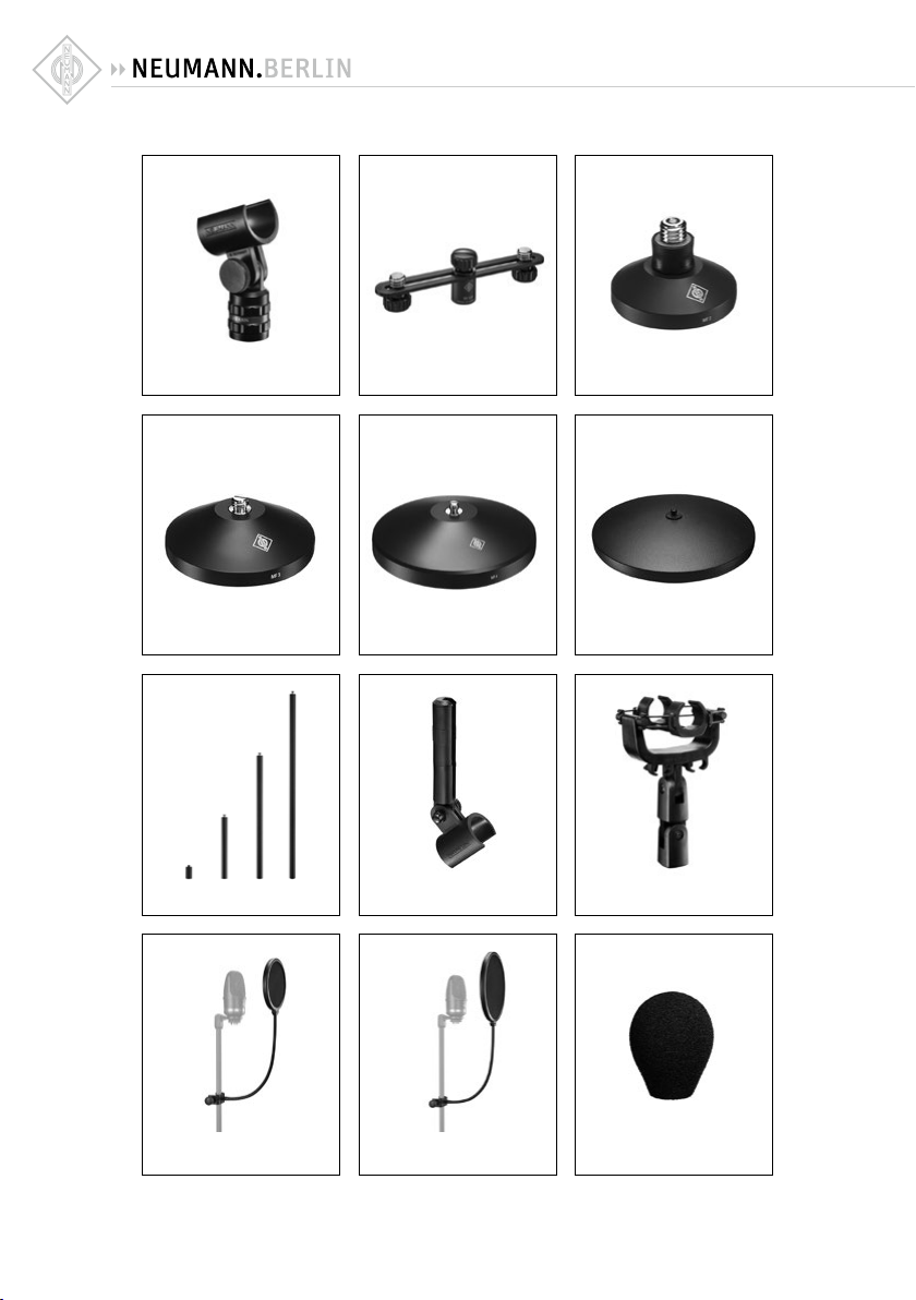
11. Ausgewähltes Zubehör*
(Fotos im Anhang)
Stativgelenke und mechanische Adapter
SG 21 bk ................... sw ................. Art.-Nr. 008613
(gehört zum Lieferumfang)
DS 120 ..................... sw ................. A rt.- Nr. 007 343
Tisch- und Fußbodenständer
MF 2 .........................sw ................. Art.-Nr. 007266
MF 3 .........................sw ................. Art.-Nr. 007321
MF 4 .........................sw ................. Art.-Nr. 007337
MF 5 .........................gr .................. Ar t.-N r. 008489
Stativverlängerungen
STV 4 ....................... sw ................. Ar t.-Nr. 006190
STV 20 ..................... sw ................. Art.-Nr. 006187
STV 40 .....................sw ................. Art.-Nr. 006188
STV 60 .....................sw ................. Ar t.-Nr. 006189
Mikrofonneigevorrichtungen
MNV 21 mt ............... sw ................. Art.-Nr. 006802
Elastische Auängung
EA 2124 A mt ...........sw ................. Art.-Nr. 008433
Popschutz
PS 15 ........................ sw ................. Art .-Nr. 0 08472
PS 20a ..................... sw ................. Art.-Nr. 008488
Windschirme
WNS 100 ................. sw. ................ Art.-Nr. 007323
(gehört zum Lieferumfang)
WNS 110 .................. sw ................. Art.-Nr. 0 08535
WS 100 ....................sw ................. Art.-Nr. 006751
Netzgerät
N 248 ....................... sw ................. Art.-Nr. 008537
Anschlusskabel
IC 3 mt .....................sw ................. Art.-Nr. 006543
Bedeutung der Farbcodierungen:
ni = nickel, sw = schwarz, gr = grau
* Ausführliche Beschreibungen un d weitere Artikel
nden Sie in unserem Zubehörkatalog oder unter
www.neumann.com
DE DE
4

12. Einige Hinweise zur Pege von
Mikrofonen
Staubschutz verwenden:
Mikrofone, die nicht im Einsatz sind, sollte man
nicht auf dem Stativ einstauben lassen. Mit einem
Staubschutzbeutel (nicht fusselnd) wird dies verhindert. Wird ein Mikrofon längere Zeit nicht verwendet, sollte es staubgeschützt bei normalem
Umgebungsklima auewahrt werden.
Popschutz verwenden:
Ein Popschutz hat nicht nur die Aufgabe, bei Gesangsaufnahmen die Entstehung von Poplauten
zu verhindern. Er vermeidet auch ezient, dass
sich von der Feuchtigkeit des Atems bis hin zu
Essensresten unerwünschte Partikel auf der Membran ablagern.
Keine überalterten Windschutze verwenden:
Auch Sch aumsto altert . Das Material ka nn brüchig
und krümelig werden. Anstatt das Mikrofon zu
schützen, kann er dann zur Verunreinigung der
Mikrofonkapsel führen. Überalterte Windschutze
also bitte entsorgen.
Funktionstest:
Moderne KondensatorMikrofone nehmen durch
lautes Ansprechen keinen Schaden. Zur Kontrolle,
ob ein solches Mikrofon angeschlossen ist, sollte
man es aber keinesfalls anpusten oder anpoppen,
da dies einem akustischen Signal von mehr als
140dB (!) entsprechen kann. Normale Sprache
genügt zum Funktionstest völlig.
Selbsthilfe kann teuer sein!
Leider kommt es doch vor, dass durch eine
Selbst reparatur mehr b eschädigt al s behoben wir d.
Insbesondere das Reinigen verschmutzter Kapseln erfordert viel Erfahrung und die Hand eines
Fachmanns . Der Lackschutz auf Pl atinen zeigt u.a.
an, dass dort nicht gelötet werden darf. Einige
Bauteile sind speziell selektiert und können nicht
durch Material von der Stange ersetzt werden. Um
unnötige Kosten zu vermeiden, empehlt sich die
Einsendung an unsere Vertretungen oder an uns.
Inspektion durchführen lassen:
Regelmäßiges Durchchecken des Mikrofonbestands
kann bei der Früherkennung von Schäden helfen. Leichte Verschmutzungen lassen sich eher
beseitigen, als eine untrennbar in die Membran
eingebrannte Nikotinschicht. Insbesondere bei
Mikrofonen im Verleih und in verunreinigenden
Umgebungen empehlt sich die regelmäßige Kontrolle, deren Kosten im Vergleich zu einer aufwendigen Reparatur sehr gering sind.
5

1. Introduction
This manual contains essential information for
the operation and care of the product you have
purchased. Please read the instructions carefully
and compl etely before using the equip ment. Please
keep this manual where it will be accessible at all
times to all current and future users.
Additional information, in particular concerning
available accessories and Neumann service partners, can always be found on our website: www.
neumann.com.
This series features:
• exceptionally low inherent self-noise and highest overload capability
• the reliable transformerless “fet 100®” circuit
design
• exceptionally clear sound reproduction free of
coloration
• very smooth frequency curves, matching
0° sound incidence, with the pressure-gradient transducers KM 184 and KM 185. Signals
within a pick-up angle of ± 135° are reproduced
without any coloration.
2. Safety instructions
Before connecting the microphone please read
the included Safety Guide and Quick Guide! Also
available for download at www.neumann.com.
Repairs and servicing are to be carried out only by
experienced, authorized service personnel. Unauthorized opening or modication of the equipment
shall void the warranty.
Use the equipment o nly under the conditions s pecied in the “Technical data” section.
Allow the e quipment to adjust to the ambient temperature before switching it on.
Do not operate the equipment if it has been damaged during transport.
Always run cables in such a way that there is no
risk of tripping over them.
Unless required for operation, ensure that liquids
and electrically conductive objects are kept at
a safe distance from the equipment and its connections.
Do not use solvents or aggressive cleansers for
cleaning purposes.
Dispose of the equipment in accordance with the
regulations applicable to the respective country.
3. Description
The microphone has the intended purpose of converting acoustic signals into electrical signals.
The “Series 180” condenser miniature microphones use the “ fet 100®” technique with a transformerless microphone circuit and capsules with
omnidirectional (KM 183), cardioid (KM 184) and
hypercardioid (KM 185) pick-up patterns.
4. Delivery includes
• Microphone
• Swivel mount SG 21 bk
• Windscreen WNS 100
5. Getting Started
Mounting the microphone
Attach the microphone to a stable, sturdy stand.
Use an elastic suspensio n, for the mechanic al sup-
pression of structure-borne noise.
If required, use a windscreen or popscreen from
our range of accessories in order to suppress wind
or pop noise.
Connecting the microphone
Caution: An incorrect power supply can
damage the microphone!
When connecting the cables, ensure that the connectors are locked correctly.
Caution: Very loud noise can damage loud-
speakers or your hearing!
Minimize the volume of connected playback and
recording equipment before connecting the microphone.
Using a suitable cable, connect the microphone to
the microphone input of the audio equipment to
be used for subsequent processing.
Switch on the P48 phantom power supply of your
audio equipment.
Gradually increase the volume of the connected
equipment. Set the gain of the connected equipment so that no distortion occurs at the highest
sound pressure level.
6
EN EN

Suppressing noise interference
The frequency response of the microphones extends to ver y low frequenc ies. The microp hone is of
course correspondingly sensitive to low-frequency
interference such as structure-borne noise and
wind or pop noise. Depending upon the situation,
the use of an elast ic suspension, a windscreen and/
or a popscreen is therefore recommended.
Function test
Simply speak into the microphone. Do not blow
into the microphone or subject it to pop noise,
since this can easily result in hazardous sound
pressure levels.
6. Shutdown and Storage
Before s witching o the microphone or disconnec ting the cables, reduce the volume of connected
equipment.
Disconnect the cables.
When disconnecting a cable, always pull only on
the connector and not on the cable itself.
Microphones which are not in use should not be
allowed to remain on the stand gathering dust.
A microphone which is unused for a prolonged
perio d should be stored under nor mal atmospher ic
conditions, and should b e protected from dust. For
this purpose, use a lint-free, air-permeable dust
cover or the orig inal packaging of the micr ophone.
7. Conguration of the Microphone Output
The microphone has a balanced output. The 3-pin
XLR connector has the following pin assignments:
Pin 1: 0 V/ground
Pin 2: Modulation (+phase)
Pin 3: Modulation (–phase)
8. Power Supply
The “Series 180” microphones operate on 48 V
phantom power (P48, IEC 61938). All P48 power
supplies in accordance with IEC 61938 which provide at least 3.2 mA per channel, are suitable for
powering the microphones.
With phantom powering the dc from the positive
supply terminal is divided via two identical resistors, one half of the dc owing through each audio
(modulation) conductor to the microphone, and
returning to the volta ge source via the c able shield.
Phantom powering provides a fully compatible
connecting system, since no potential dierences
exist between the two audio conductors.
Studio outlets so powered will therefore also
accept dynamic microphones and ribbon microphones as well as the modulation conductors of
tube-equipped condenser microphones without
the need to switch o the dc supply voltage.
No harm is done even if a N eumann phantom power
supply is connected to the inputs of microphones
which are phantom powered from another source.
9. Microphone Cables
The electroacoustic properties of the microphones
are not aected even by very long (Neumann) cables. However, if cab les are well over 300 m, a fallo in the upp er frequency r ange become s apparent.
Neumann oers a wide range of cables. Only a
selection is presented here. Other cable lengths
or cable materials without connectors are available on request.
IC mt ................blk ............ Cat. No.
Microphone cable with double twist (double helix)
braiding as shield. Ø 5 mm, leng th 10 m. XLR 3 connectors, matte black.
At the power supply unit, the audio signal is
available at a 3-pin XLR socket which requires an
XLR3F connector. The microphone is wired as
per IEC 60268-4:
An increase in sound pressure at the microphone‘s
front diaphragm produces a positive voltage at
pin 2.
7

10. Technical Specications
Permissible atmospheric conditions:1)
Operating temperature range ............0 °C … +70 °C
Humidity range ......................... 0 %…75 % r el. hum
Storage temperature range ............–20 °C … +70 °C
Humidity range .........................0 %…95 % rel. hum
Acoustical op. principle .............Pressure/Pressure
Polar pattern ............... Omnidirectional/Cardioid/
Frequency range .............................. 20 Hz...20 kHz
Sensitivity
2)
..........................1 2/15/ 10 mV/Pa ± 1 dB
Rated impedance ....................................... 50 ohms
Rated load impedance ......................... 1000 ohms
Signal-to-noise ratio
4)
CCIR
.................................................. 70/ 72/70 d B
Signal-to-noise ratio
A-weighted4) ........................................81/81/79 dB
Equivalent noise level,
4)
CCIR
...................................................24/22/24 dB
Equivalent noise level,
A-weighted
4)
.....................................13/13/1 5 dB-A
Maximum SPL
for less than 0.5 % THD
Max. output voltage ......................................10 dBu
Supply voltage
6)
...................................... 48 V ± 4 V
Current consumption
Matching connector ..................................... XLR 3F
Weight ................................................. approx. 80 g
Dimensions ............................... Ø 22 mm x 107 mm
94 dB SPL ≙ 1 Pa = 10 µbar
0 dB ≙ 20 µPa
1) All valu es are for n on-c ondens ing humidi ty. The val ues are va lid for
clean and w ell-lo oked-a er micro phone s or microp hone ca psules ,
respe ctivel y. Any kind o f pollut ion of cap sules an d membra nes may
restr ict the said v alues
2) at 1 k Hz into 1 kohms r ated load impe dance.
3) re 94 d B SPL
4) a ccording to IE C 60268-1;
CCIR- weighting a cccording to CC IR 468-3, q uasi peak;
A-wei ghting acco rding to IEC 61672 -1, RMS
5) TH D of micropho ne amplier at a n input voltag e equivalent t o the cap-
sule outp ut at the spec ied SPL.
6) P hantom power ing (P48, IEC 61938).
gradient transducer
Hypercardioid
3)
,
3)
,
5)
............ 1 40/13 8/142 dB
6)
................................. 3.2 mA
11. Selected Accessories*
(see photos in appendix)
Stand Mounts and Mechanical Adapter
SG 21 bk ................... blk ................ Cat. No 008613
(included in the supply schedule)
DS 120 ..................... blk ................ Cat. No 007343
Table and Floor Stands
MF 2 .........................blk ................ Cat. No 007266
MF 3 .........................blk ................ Cat.No. 007321
MF 4 .........................blk ................ Cat.No. 007 337
MF 5 .........................gr .................. Cat.No. 008489
Stand Extensions
STV 4 ....................... blk ................ Cat.No. 006190
STV 20 ..................... blk ................ Cat.No. 006187
STV 40 .....................blk ................ Cat.No. 006188
STV 60 .....................blk ................ Cat.No. 006189
Auditorium Hangers
MNV 21 mt ............... blk ................ Cat.No. 006802
Elastic Suspension
EA 2124 A mt ...........blk ................ Cat. No 008433
Popscreen
PS 15 ........................ blk ................ Cat.No. 008472
PS 20a ..................... blk ................ Cat.No. 008488
Foam Windscreen
WNS 100.................. blk..........Cat. No...007323
(included in the supply schedule)
WNS 110 .................. blk ................ Cat. No 008535
WS 100 ....................blk ................ Cat. No 006751
Power supply
N 248 ....................... blk ................ Cat. No 008537
Connecting Cables
IC 3 mt .....................blk ................ Cat.No. 006543
Meaning of color codes:
ni = nickel, blk = black, gr = grey
* Detailed descriptions and additional articles
can be found in our accessories catalog or at:
www.neumann.com
8
EN EN

12. Hints on Microphone Maintenance
Use a dust cover:
Microphones not in use should not be le on the
stand gathering dust. This can be prevented by the
use of a non-uy dust cover. When not in use for
a longer period, the microphone should be sealed
against dust and stored under standard climatic
conditions.
Use a pop screen:
A pop screen not only prevents the occurrence of
plosive pop noises in vocal recordings, but also
eciently prevents unwanted particles, from respirator y moisture to food remnants , from settling
on the diaphragm.
Avoid the use of old wind shields:
As the foam material of a wind shield ages it can
become brittle and crumbly. Instead of protecting
the microphone, an old wind shield can thus lead
to soiling of the microphone capsule. Therefore
please dispose of worn-out wind shields.
Function testing:
Although modern condenser microphones are not
harmed by high sound pressure level s, one should
under no circumstances use a pop-test to check
whether the microphone is connected and the
channel on the mixing console is pulled up, since
this can re sult in sound pres sure levels of over 140
dB! Normal speech is quite sucient for function
testing.
Do-it-yourself repairs can be expensive!
Unfortunately, do-it-yourself repairs sometimes do
more harm than good. Cleaning soiled capsules in
particular requires considerable experience and
an expert touch. The protective lacquer on circuit boards indicates, among other things, places
which must not be soldered. Certain components
are specially selected and cannot be replaced by
standard part s. To avoid unnecess ary expense , we
recommend sending defective microphones to us
or our representatives for servicing.
Regular inspections:
Sending in microphones regularly for inspection
can aid in the early detection of damage. Slight
soiling can be removed much more easily than
a nicotine layer inextricably bonded to the diaphragm . Regular inspec tions are particularly to be
recommended for microphones which are rented
or are used in dusty or smoky environments , since
the costs are low in comparison with the cost of a
major overhaul.
9
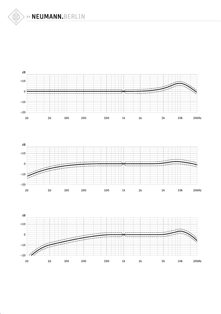
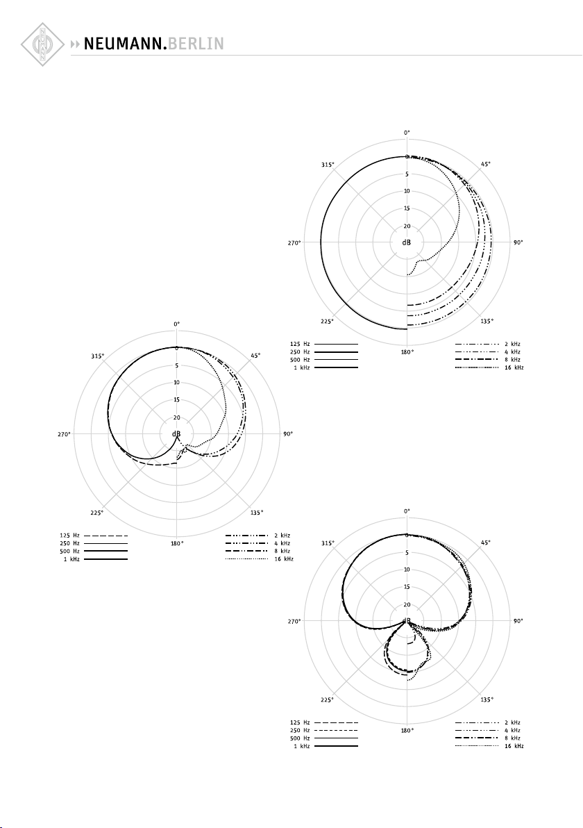
13. Frequenzgänge und Polardiagramme
Frequency Responses and Polar Patterns
KM 183
KM 184
KM 185
gemes sen im freien Sc hallfeld nac h IEC 60268- 4, Toleranz ±2 dB
measure d in free- eld conditi ons (IEC 6026 8-4), toler ance ±2 dB
10
11
SG 21 bk
DS 120
MF 2
MF 3
STV...
PS 15
MF 4
MNV 21 mt
PS 20a
MF 5
EA 2124 A mt
WNS 100
12
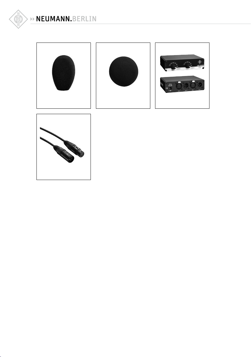
WNS 110
IC 3 mt
WS 100 N 248
13

Herstellererklärungen
Garantie
Die Georg Neumann GmbH übernimmt für
dieses Produkt eine Garantie von 24 Monaten. Die für dieses Produkt geltenden aktuellen Garantiebedingungen finden Sie auf
www.neumann.com.
In Übereinstimmung mit den folgenden Anforderungen
• WEEE-Richtlinie (2012/19/EU)
WEEE-Reg.-Nr.: DE 41402700
Hinweise zur Entsorgung
Das Symbol der durchgestrichenen Mülltonne auf
Rädern auf Produkt und/oder Verpackung weist
Sie darauf hin, dass diese Produkte am Ende ihrer
Lebensdauer nicht über den normalen Hausmüll
entsorgt werden dürfen, sondern einer separaten
Entsorgung zuzuführen sind. Für Verpackungen
beachten Sie bitte die gesetzlichen Vorschrien
zur Abfalltrennung in Ihrem Land.
Weitere Informationen zum Recycling dieser Produkte erhalten Sie bei Ihrer Gemeindeverwaltung,
den kommunalen Sammel- oder Rücknahmestellen
oder bei Ihrem Neumann-Partner.
Das sepa rate Sammeln von Elektro - und Elektron ikAltgeräten, Batterien/Akkus (wenn vorhanden) und
Verpackungen dient dazu, die Wiederverwendung
und/oder Verwertung zu fördern und negative Effekte, beispielsweise durch potenziell enthaltene
Schadstoffe, zu vermeiden. Hiermit leisten Sie
einen wichtigen Beitrag zum Umwelt- und Gesundheitsschutz.
Anforderungen werden erfüllt für:
EMV
EN 551 03-2
Europe
Australien/
Neuseeland
Safety
EN 5503 2
EN 60065
EN 62 368-1
Warenzeichen
Neumann® ist ein eingetragenes Warenzeichen der
Georg Neumann GmbH.
Haungsausschluss
Die Georg Neumann GmbH übernimmt keinerlei Haung für Folgen eines unsachgemäßen
Gebrauchs des Produkts, d.h. die Folgen eines
Gebrauchs, der von den in der Bedienungsanleitung genannten technischen Voraussetzungen
abweicht (z.B. Bedienungsfehler, mechanische
Beschädigungen, falsche Spannung, Abweichung von empfohlenen Korrespondenzgeräten).
Jegliche Haung der Georg Neumann GmbH für
Schäden und Folgeschäden, die dem Benutzer
aufgrund eines solchen abweichenden Gebrauchs
entstehen sollten, wird ausgeschlossen. Ausgenommen von diesem Haungsausschluss sind
Ansprüche aufgrund zwingender gesetzlicher Haftung, wie z.B. nach Produkthaungsgesetz.
DE
CE-Konformität
• RoHS (2011/65/EU)
• Niederspannungsrichtlinie (2014/35/EU)
• EMV-Richtlinie (2014/30/EU)
Die Erklärungen stehen auf der Produktseite unter
www.neumann.com zur Verfügung.
14

Manufacturer Declarations
Warranty
Georg Neumann GmbH gives a warranty of
24months on this product. For the current terms
and conditions of the product guarantee, please
visit www.neumann.com.
In compliance with the following requirements
• WEEE-Richtlinie (2012/19/EU)
WEEE-Reg.-Nr.: DE 41402700
Notes on disposal
The symbol of the crossed-out wheeled bin on
the product and/or the packaging indicates that
these products must not be disposed of with normal household waste, but must be disposed of
separately at the end of their op erational lifet ime.
For packaging disposal, please observe the legal
regulations on waste segregation applicable in
your country.
Further information on the recycling of the se products can be obtained from your municipal administration, from the municipal collection points, or
from your Neumann partner.
The separate collection of waste electrical and
electronic equipment, batteries/rechargeable batteries (if applicable) and packagings is used to
promote the reuse and recycling and to prevent
negative eec ts caused by e. g. potentially hazardous substances containe d in these produc ts. Herewith you make an important contribution to the
protection of the environment and public health.
EU Declaration of Conformity
• RoHS (2011/65/EU)
• Low voltage directive (2014/35/EU)
• EMV-Directive (2014/30/EU)
The declaration is available on the product page
at www.neumann.com.
In compliance with
Europe
Australia/
New Zeeland
EMV
Safety
EN 551 03-2
EN 5503 2
EN 60065
EN 62 368-1
FOR AUSTR ALIA ONLY
Neumann goods come with g uarantees that c annot
be excluded under the Australian Consumer Law.
You are entitled to a replacement or refund for a
major failure and compensation for any other reasonably foreseeable loss or damage. You are also
entitled to have the goods repaired or replaced if
the goods fail to be of acceptable quality and the
failure does not amount to a major failure.
This warr anty is in addition to other r ights or remedies under law. Not hing in this warrant y excludes,
limits or m odies any liabilit y of Neumann which is
imposed by law, or limits or modies any remedy
available to the consumer whic h is granted by law.
To make a claim under this warranty, contact:
Sennheiser Australia Pty Ltd, Unit 3, 31 Gibbes
Street Chatswood NSW 2067, AUSTRALIA .
Phone: (02) 9910 6700,
email: service@sennheiser.com.au
All expenses of claiming th e warranty will be borne
by the person making the claim. The Neumann
International Warranty is provided by Sennheiser
Australia Pty Ltd (ABN 68 165 388 312), Unit 3,
31 Gibbes Street Chatswood NSW 2067 Australia.
Trademarks
Neumann® is a registered trademark of Georg
Neumann GmbH.
Limitation of Liability
Georg Neumann GmbH shall not be liable for consequences of an inappropriate use of the product
not being in compliance with the technical allowance in the user manual such as handling errors,
mechanical spoiling, fal se voltage and using other
than the recommended correspondence devices.
Any liabilit y of Georg Neumann GmbH for any damages including indirect, consequential, special,
incidental and punitive damages based on the
user’s non-compliance with the user manual or
unreasonable utilization of the product is hereby
15
EN

excluded as to the extent permitted by law. This
limitation of liability on damages is not applicable
for the liability under European product liability
codes or for users in a state or countr y where such
damages cannot be limited.
China RoHS
部件名称 (Parts)
*= 如果包含 (if available)
金属部件
(Metal Parts)
电路模块
(Circuit Modules)
电缆及电缆组件
(Cables and Cable Assemblies)
本表格依据 SJ/T 11364 的规定编制。
o:表示该有害物质在该部件所有均质材料中的含量均在
GB/T 26572规定的限量要求以下。
x:表示该有害物质至少在该部件的某一均质材料中的含量超出
GB/T 26572规定的限量要求 。
20
有害物质
)
6+
铅 (Pb)
汞 (Hg)
(PBB)
镉 (Cd)
多溴联苯
多溴二苯醚
六价铬 (Cr
x o o o o o
x o o o o o
x o o o o o
Việt nam
Kể từ ngày 1 tháng 1 2 năm 2012, các sản phẩm
được sản xuất bởi Neumann tuân thủ Thông tư
30/2011/ TT-BCT quy định về giới hạn cho phép
đối với một số chất độc hại trong các sản phẩm
điện v à điện tử.
(PBDE)
Irrtümer und technische Änderungen vorbehalten • Errors excepted, subject to changes
Printed in Germany • Publ. 07/20 539525/A03
 Loading...