

Page 1
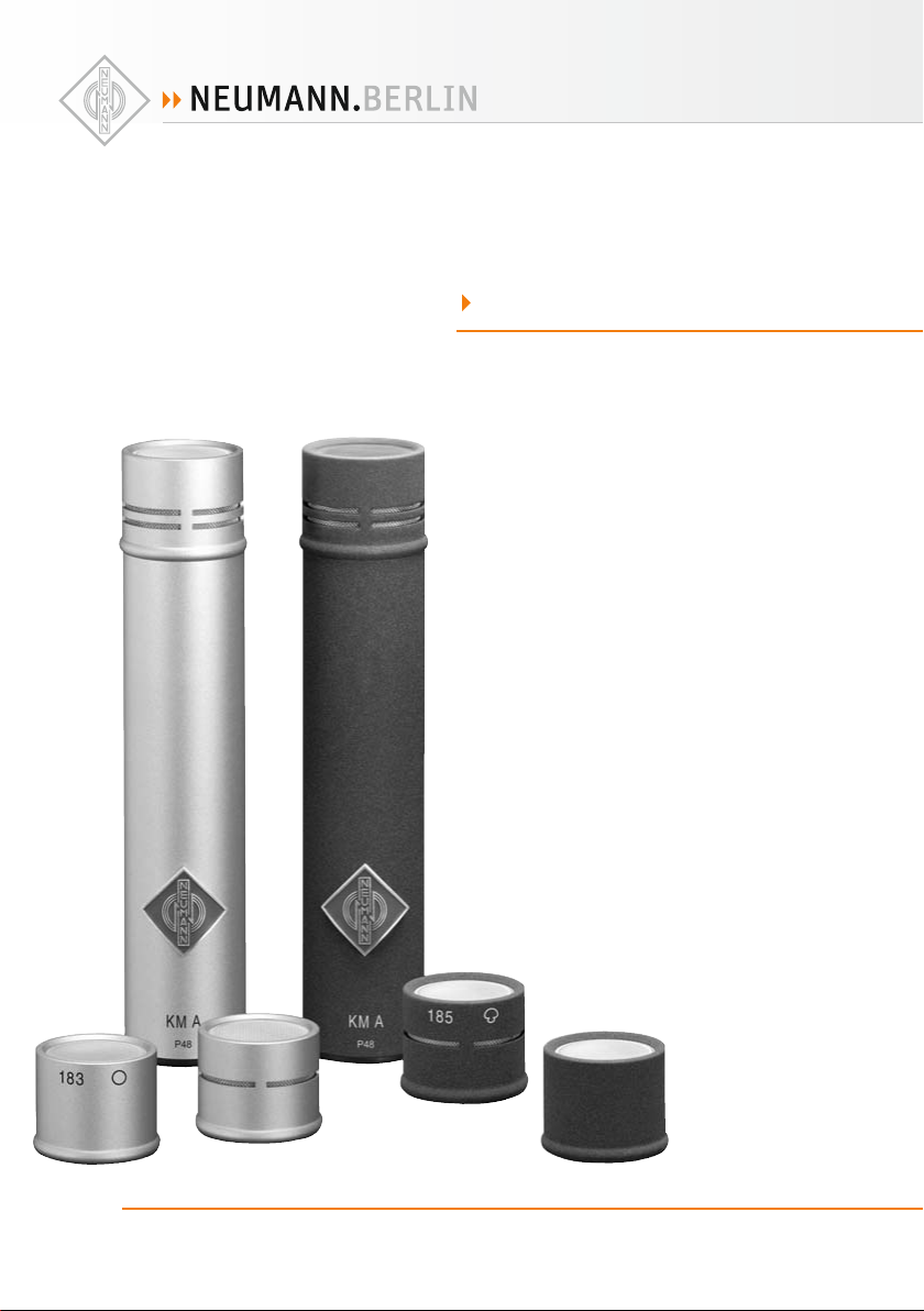
KM A
B
O M
· . · ·
() / - · - · @. · ..
Page 2
1. Einleitung
In dieser Anleitung fi nden Sie alle wichtigen Informationen für den Betrieb und die Pfl ege der
von Ihnen erworbenen Produkte. Lesen Sie diese
Anleitung sorg fältig und vollständig, bevor Sie die
Geräte benutzen. Bewahren Sie sie so auf, dass
sie für alle momentanen und späteren Nutzer jederzeit zugänglich ist.
Weitergehende Informationen, insbesondere
auch zu den verfügbaren Zubehörteilen und den
Neumann-Servicepartnern, fi nden Sie jederzeit
auf unserer Website www.neumann.com. Die
Servicepartner können Sie auch telefonisch unter
+49 (0) 30 / 41 77 24 - 0 er fragen.
Auf unserer Website www.neumann.com fi nden
Sie in der Rubrik Downloads ergänzend folgende
PDF-Dateien:
Betrieb an unsymmetrischen oder mittengeer-•
deten Eingängen
Hinweise zur Pfl ege des Mikrofons•
Zum weltweiten Erfahrungsaustausch unter Neumann-Anwendern bieten wir auf unserer Website
das Neumann Online-Forum an, das sich durch
die integrierte Archivfunktion zu einem umfangreichen Know-How-Pool entwickelt hat.
2. Sicherheitshinweise
Der bestimmungsgemäße Gebrauch dieses Mikrofons ist die Wandlung akustischer in elektrische
Signale.
Schließen Sie das Mikrofon nur an Mikrofon-
eingänge und Speisegeräte an, die eine 48 VPhantomspeisung nach IEC 61938 liefern.
Reparatur- und Servicearbeiten dürfen nur von
erfahrenem und autorisiertem Fachpersonal
durchgeführt werden. Wenn Sie das Gerät eigenmächtig öff nen oder umbauen, erlischt die Gewährleistung.
Verwenden Sie das Gerät nur unter den in den
technischen Daten angegebenen Betriebsbedingungen.
Lassen Sie das Gerät auf Raumtemperatur akklimatisieren, bevor Sie es einschalten.
Nehmen Sie das Gerät nicht in Betrieb, wenn es
beim Transport beschädigt wurde.
Verlegen Sie Kabel stets so, dass niemand darüber
stolpern kann.
Halten Sie Flüssigkeiten und elektrisch leitfähige
Gegenstände, die nicht betriebsbedingt notwendig sind, vom Gerät und dessen Anschlüssen fern.
Verwenden Sie zum Reinigen keine Lösungsmittel
oder aggressiven Reinigungsmittel.
Entsorgen Sie das Gerät nach den Bestimmungen
Ihres Landes.
3. Kurzbeschreibung
KM A-Kleinmikrofone sind Studio-Kondensatormikrofone in transformatorloser Schaltungstechnik
(TLM).
Für die KM A-Kleinmikrofone bietet Neumann austauschbare Kapseln und diverses Zubehör. Damit
wird ein Höchstmaß an Flexibilität erreicht.
Durch den Austausch der KM A- durch eine KM DAusgangsstufe ist bei Beibehaltung der Kapseln
und ihrer akustischen Eigenschaften ein einfacher
Wechsel in die digitale Welt der Solution-D-Familie mit ihren Vorteilen der integrierten AD-Wandlung und den umfangreichen DSP-Funktionen
möglich.
Mit seinem transformatorlosen Konzept ermöglichen KM A-Mikrofone eine besonders saubere,
verfärbungsfreie Klangübertragung und höchste
Aussteuerbarkeit bei geringem Eigenrauschen.
Mit dem Schalter auf der Rückseite wird eine Vordämpfung von 10 dB eingestellt. Damit erhöht
sich der maximale Schalldruckpegel, aber auch
der Ersatzgeräuschpegel um 10 dB.
Die KM A-Kleinmikrofonserie ist ein modulares
System mit austauschbaren Mikrofonkapseln.
Es sind Kapseln mit folgenden Richtcharakteristiken verfügbar:
KK 120 (nx): Acht, querliegend
KK 131 (nx): Kugel, freifeld-entzerrt
KK 133 (nx): Kugel, diff usfeld-entzerrt,
mit Schallbeugungskugel SBK 133
KK 143 (nx): Breite Niere
KK 145 (nx): Niere mit Hochpass
KK 183 (nx): Kugel, diff usfeld-entzerrt
KK 184 (nx): Niere
KK 185 (nx): Hyperniere
Die Kapseln können auch einzeln bezogen werden. Alle Teile sind jeweils klassisch nickelfarben
oder in refl exionsfreier schwarz-matter Nextelbeschichtung (nx) erhältlich.
4. Inbetriebnahme
Mikrofon einrichten
Befestigen Sie das Mikrofon mit der dafür vorgesehenen Halterung auf einem ausreichend stabilen und standfesten Stativ etc. Verwenden Sie
ggf. eine elastische Aufhängung aus unserem Zubehör-Angebot, um Trittschall durch mechanische
Entkopplung zu unterdrücken.
Extrem niederfrequente Signale können durch
Störungen wie Körperschall oder Pop- und Windgeräusche hervorgerufen werden. Um solche
Störsignale zu unterdrücken, empfehlen wir, eine
elastische Aufhängung, einen Windschutz oder
einen Popschirm aus unserem Zubehörprogramm
zu verwenden.
Mikrofon anschließen
Vorsicht: Eine falsche Versorgungsspannung
kann das Mikrofon beschädigen!
Schließen Sie das Mikrofon ausschließlich an
ein Netzgerät, einen Mikrofon-Vorverstärker, ein
Mischpult o.Ä. mit 48 V-Phantomspeisung nach
IEC 61938 an. Sie können alle P48-Speisegeräte
verwenden, die mindestens 3,5 mA je Kanal abgeben.
Vorsicht: Sehr hohe Signalpegel können Ihr
Gehör und Ihre Laut sprecher schädigen!
Reduzieren Sie an den angeschlossenen Wiedergabegeräten die Lautstärke, bevor Sie das Mikrofon anschließen, auch wegen der Gefahr der akustischen Rückkopplung.
Verbinden Sie das Mikrofon über ein geeignetes
Kabel mit dem Mikrofoneingang Ihres weiterverarbeitenden Audiogerätes bzw. mit dem vorgesehenen P48-Speisegerät. Hinweise zur Anschlussbelegung fi nden Sie im Kapitel Technische Daten.
Kabellängen bis ca. 300 m zwischen Mikr ofon und
nachfolgendem Verstärkereingang haben keinen
Einfl uss auf den Frequenzgang des Mikrofons.
Achten Sie beim Anschließen von Kabeln auf die
korrekte Verriegelung der Steckverbinder. Verlegen Sie die Kabel so, dass sie keine Stolpergefahr
darstellen.
Erhöhen Sie an den weiter verarbeitenden Geräten
schrittweise den Lautstärkepegel.
Stellen Sie die Vorverstärkung (Gain) Ihre s weiterverarbeitenden Gerätes so ein, dass bei höchstem
Pegel keine Verzerrungen auftreten.
Störschallunterdrückung
Der Übertragungsbereich des KM A-Mikrofons
reicht bis unter 20 Hz. Entsprechend empfi ndlich
ist das Mikrofon natürlich auch für tieff requente
Störungen wie Körperschall oder Wind- und Popgeräusche. Daher empfi ehlt sich ggf. die Verwendung einer elastischen Aufhängung, eines Windschutzes und/oder eines Popschirmes.
Tontest
Sprechen Sie das Mikrofon einfach nur an. Anpusten oder „Anploppen“ führt zu gefährlichen
Schalldruckpegeln.
5. Außerbetriebnahme und Aufbewahrung
Verringern Sie vor der Außerbetriebnahme und
dem Abziehen von Kabeln den Lautstärkepegel
Ihres weiterverarbeitenden Gerätes.
Ziehen Sie beim Lösen von Kabeln stets nur an
den Steckverbindern und nicht am Kabel.
Mikrofone, die nicht im Einsatz sind, sollte man
nicht auf dem Stativ einstauben lassen. Wird ein
Mikrofon längere Zeit nicht verwendet, sollte es
bei normalem Umgebungsklima staubgeschützt
aufbewahrt werden. Verwenden Sie hierfür einen
nicht fusselnden, luftdurchlässigen Staubschutzbeutel oder die Originalverpackung des Mikrofons.
2
D
3
D
Page 3
6. Technische Daten
Zulässige klimatische Verhältnisse:1)
Betriebstemperaturbereich .............. 0 °C … +40 °C
Lagerungstemperaturbereich........–20 °C … +70 °C
Feuchtebereich ......................0 % … 90 % rel. hum.
0 % … 85 % rel. hum.
bei +20 °C
bei +60 °C
40 mm x
130 mm x
Acht,
seitliche
Einspra-
che
Hyper-
niere
Hochpass
Niere Niere mit
Breite
Niere
Kugel,
Diff usfeld-
entzerrt
140 dB
150 dB
142 dB
152 dB
138 dB
148 dB
138 dB
148 dB
138 dB
148 dB
140 dB
150 dB
24 mm
108 mm x
22 mm
108 mm x
22 mm
108 mm x
22 mm
108 mm x
22 mm
108 mm x
22 mm
24 mm
18 mm x
22 mm
18 mm x
22 mm
18 mm x
22 mm
18 mm x
22 mm
18 mm x
22 mm
38 mm x
Gewicht Kapsel 11 g 49 g 11 g 15 g 15 g 15 g 19 g 37 g
22 mm
22 mm
Abmessungen (L x Ø) Kapsel 18 mm x
5
D
128 mm x
Kugel,
Diff usfeld-
entzerrt
Freifeld-
entzerrt
Bei 0 dB Vordämp fung und 0 dB Gain.
1)
Alle Werte für nicht-kondensierende Feuchtigkeit.
2)
bei 1 kHz , 0 dB Verstärk ung und 94 dB SPL
3)
be zogen auf 94 dB SPL
4)
nach IEC 6 0268-1;
CCIR-Bew ertung nach CCIR 468-3, Qua si-Spitzenwert;
A-Be wertung na ch IEC 61672-1, Eff ektivwert
4
D
Typ KK 131 KK 133 KK 183 KK 143 KK 184 KK 145 KK 185 KK 120
Akustische Arbeitsweise Druckempfänger Druckgradientenempfänger
Richtcharakteristik Kugel,
12 mV/Pa 15 mV/Pa 12 mV/Pa 1 5 mV/Pa 15 mV/Pa 14 mV/Pa 10 mV/Pa 12 mV/Pa
2)
Übertragungsbereich 20 – 20.000 Hz
Feldübertragungsfaktor
70 dB 66 dB 69 dB 70 dB 70 dB 70 dB 69 dB 69 dB
81 dB 79 dB 81 dB 81 dB 81 dB 80 dB 78 dB 79 dB
24 dB 28 dB 24 dB 22 dB 22 dB 22 dB 24 dB 25 dB
13 dB 15 dB 13 dB 13 dB 13 dB 14 dB 15 dB 15 dB
4)
,
3)
Geräuschpegelabstand
4)
4)
A-bewertet
Ersatzgeräuschpegel, CCIR
Ersatzgeräuschpegel,
, CCIR
3)
Nennimpedanz 50 Ohm
Nennlastimpedanz 1.000 Ohm
Geräuschpegelabstand
138 dB
148 dB
140 dB
150 dB
4)
Speisespannung (P48, IEC 61938) 48 V
Stromverbrauch (P48, IEC 61938) max. 3,5 mA
A-bewertet
Grenzschalldruckpegel3)für K < 0,5%
für K < 0,5% mit Vordämpfung
Steckve rbinder XLR 3 M
22 mm
22 mm
Gewicht Ausgangsstufe 70 g
Abmessungen (L x Ø) Mikrofon 108 mm x
Page 4
7. Lieferumfang
Mikrofon Mikrofon Mikrofon Stereo-Set Ausgangsstufe
Mikrofon KM 1xx A (nx) Mikrofon
KM 133 A (nx)
Stativgelen k SG 21 bk Stativ gelenk SG 2 1 bk 2 Stat ivgelenke SG 21 b k Stativgelenk SG 21 bk
Windschutz WNS 100 Schallbeugungskugel
SBK 133
Bedienungsanleitung Bedienungsanleitung Bedienungsanleitung Bedienungsanleitung
Holzetui Holzetui Holzetui Holzetui
2 Mikrofone
KM 1xx A (nx)
2 Windschutze WNS 100 Windschutz WNS 100
Mikrofonausgangs stufe
KM A (nx)
8. Fehlercheckliste
Fehler
Keine
Funktion
Keine Signalübertragung
Ton verzerrt Falsch eingestellte Eingangsemp-
Ton klingt dumpf,
räumlich
Mögliche Ursachen
▶
Phantom-Speisespannung am
Mischpult oder am Speisegerät nicht
eingeschaltet.
Das Speisegerät ist nicht mit dem
Netzanschluss verbunden oder
Batterie fehlt.
Das Mikrofon ist nicht mit dem r ichtigen Mikrofonverstärker-Eingang des
nachfolgenden Gerätes verbunden.
fi ndlichkeit oder Vorverstärkung des
nachfolgenden Verstärkers.
Windeinfl uss Benutzen Sie einen geeigneten Windschutz
Explosivlaute Benutzen Sie einen geeigneten Popschutz
Körperschallübertragung Benutzen Sie eine geeignete elastische Aufhän-
Richtcharakteristik nicht beachtet Prüfen Sie, ob das Mikrofon von der richtigen
Abhilfe
▶
Überprüfen Sie die entsprechenden Einstellungen auf dem Kanalzug.
Überprüfen Sie Netzanschluss oder Batterie des
Speisegeräts.
Überprüfen Sie den Signalweg
Aktivieren Sie ggf. den entsprechenden Eingang
auf dem zugeordneten Kanalzug des Mischpults.
Verringern Sie die Eingangsempfi ndlichkeit oder
Vorverstärkung des nachfolgenden Gerätes so,
dass eine ausreichende Aussteuerungsreserve
bleibt.
(Zubehör).
(Zubehör).
gung (Zubehör).
Seite angesprochen wird. Orientieren Sie sich
am Neumann-Logo.
9. Zubehör* (Fotos im Anhang)
Kapseln
KK 120 .....................ni ................Best.-Nr. 008589
KK 120 nx ................nx ...............Best.-Nr. 008590
KK 131 ......................ni ................Best.-Nr. 008591
KK 131 nx .................nx ...............Best.-Nr. 008592
KK 133 .....................ni ................Best.-Nr. 008539
KK 133 nx.................nx ............... Best.-Nr. 008540
KK 143 .....................ni ................Best.-Nr. 008593
KK 143 nx ................nx ...............Best.-Nr. 008594
KK 145 .....................ni ................Best.-Nr. 008595
KK 145 nx ................nx ...............Best.-Nr. 008596
KK 183 .....................ni ................Best.-Nr. 008566
KK 183 nx ................nx ...............Best.-Nr. 008567
KK 184 .....................ni ................Best.-Nr. 008568
KK 184 nx ................nx ...............Best.-Nr. 008569
KK 185 .....................ni ................Best.-Nr. 008570
KK 185 nx ................nx ...............Best.-Nr. 008571
Ausgangsstufen
KM A .........................ni ................Best.-Nr. 008634
KM A nx ....................nx ...............Best.-Nr. 008635
KM D (44,1 kHz) ......ni ................Best.-Nr. 008578
KM D nx (44,1 kHz) .nx ...............Best.-Nr. 008581
KM D (48 kHz) .........ni ................ Best.-Nr. 008579
KM D nx (48 kHz) ....nx ............... Best.-Nr. 008582
KM D (96 kHz) .........ni ................Best.-Nr. 008580
KM D nx (96 kHz) ....nx ...............Best.-Nr. 008583
Elastische Aufhängungen
DA-K M ...................... s w ............... Be s t.-Nr. 008420
EA 2124 A mt ...........sw ............... Best.-Nr. 008433
Tisch- und Fußbodenständer
MF 2 .........................sw ............... Best.-Nr. 007266
MF 4 .........................sw ............... Best.-Nr. 007337
MZEF 8120 ..............nx ...............Best.-Nr. 502319
Mikrofonneigevorrichtung
MNV 21 mt ...............sw ............... Best.-Nr. 006802
MNV 87 mt ..............sw ...............Best.-Nr. 006806
MNV 100 .................sw ...............Best.-Nr. 006811
Stativgelenke, weitere mechanische Adapter
DS 120 .....................sw ...............Best.-Nr. 007343
MZGE 8000 ............nx ............... Best.-Nr. 502324
MZGE 8002 .............nx ............... Best.-Nr. 5 02325
SG 21 bk ...................sw ...............Best.-Nr. 008613
SG 109 .....................sw ............... Best.-Nr. 008614
SG 110 nx ................nx ............... Best.-Nr. 008611
STH 100 ..................nx ...............Best.-Nr. 007315
Kapselverlängerungen
KVG 130 nx .............nx ............... Best.-Nr. 008608
KVG 160 nx .............nx ...............Best.-Nr. 008609
KVG 1120 nx ............nx ............... Best.-Nr. 008610
Schaumstoff windschutz
WNS 100 .................sw ...............Best.-Nr. 007323
WNS 110 ..................sw ............... Best.-Nr. 008535
WS 100 ....................sw ............... Best.-Nr. 006751
Popschutz
PS 15 .......................sw ...............Best.-Nr. 008472
Anschlusskabel
IC 3 mt .....................sw ............... Best.-Nr. 006543
LC 4 - 5 nx ................nx ............... Best.-Nr. 008606
LC 4 - 10 nx .............nx ............... Best.-Nr. 008607
Speisegeräte
BS 48 i .....................sw ............... Best.-Nr. 006494
BS 48 i-2 ..................sw ............... Best.-Nr. 006496
N 248 EU .................sw ...............Best.-Nr. 008537
N 248 US .................sw ............... Best.-Nr. 008538
N 248 UK .................sw ............... Best.-Nr. 008539
Bedeutung der Farbcodierungen:
ni = nickel, nx = nextel, sw = schwarz, gr = grau
* A usführli che Besc hreibunge n und weitere A rtikel fi n den Sie
i n u n s e r e m Z u b e h ö r k a t a l o g o d e r u n t e r w w w . ne u m a n n . c o m
6
D
7
D
Page 5

1. Introduction
This manual contains essential inf ormation for the
operation and care of the products you have purchased. Please read the instructions carefully and
completely before using the equipment. Please
keep this manual where it will be accessible at all
times to all current and future users.
Additional information, in particular concerning
available accessories and Neumann service partners, can always be found on our website: www.
neumann.com. Information about service partners can also be obtained by telephone: +49 (0)
30 / 41 7 7 24 - 0.
The following related fi les are available in PDF
format in the Downloads section of our website
www.neumann.com:
Operation with Unbalanced or Center Tap •
Grounded Inputs
Some Remarks on Microphone Maintenance•
The Neumann online forum on our website enables Neumann users worldwide to share their
experiences. Through its integrated archive function, the forum has developed into an extensive
knowledge pool.
2. Safety instructions
The microphone has the intended purpose of converting acoustic signals into electrical signals.
Connect the microphone only to microphone
inputs and devices which supply 48 V of phantom power in accordance with IEC 61938.
Repairs and servic ing are to be carried out only by
experienced, authorized service personnel. Unauthorized opening or modifi cation of the equipment shall void the warranty.
Use the equipment only under the conditions
specifi ed in the “Technical data” section. Allow
the equipment to adjust to the ambient temperature before switching it on. Do not operate the
equipment if it has been damaged during transport.
Always run cables in such a way that there is no
risk of tr ipping over them.
Unless required for operation, ensure that liquids
and electrically conductive objects are kept at a
safe distance from the equipment and its connections.
Do not use solvents or aggressive cleansers for
cleaning purposes.
Dispose of the equipment in accordance with the
regulations applicable to the respective country.
3. Brief description
KM A miniature microphones are studio condens er
microphones with transformerless circuit technology (TLM).
Neumann provides interchangeable capsules and
various accessories for the KM A miniature microphones, thus ensuring maximum fl exibility.
The capsules can be used with a KM D instead of
a KM A output stage. This makes it easy to transfer the capsules with their acoustic properties to
the digital realm of the Solution-D family, so as to
take advantage of integrated A/D conversion and
extensive DSP functionality.
The transformerless design of the KM A microphones ensures exceptionally clean sound transmission free of coloration, with low self-noise and
an impressive dynamic range.
The switch on the rear engages a preattenuation
of 10 dB. This increases the maximum sound pressure level, but also the equivalent self noise level
by 10 dB.
The KM A microphone series is a modular system
which allows to change capsules with diff erent
characteristics. Capsules with the following directional characteristics are available:
KK 120 (nx): Figure-8, side fi re
KK 131 (nx): Omni free fi eld equalized
KK 133 (nx): Omni diff use fi eld equalized
with sound diff raction sphere
SBK 133
KK 143 (nx): Cardioid wide angle
KK 145 (nx): Cardioid low frequency roll-off
KK 183 (nx): Omni diff use fi eld equalized
KK 184 (nx): Cardioid
KK 185 (nx): Hypercardioid
The capsules can also be ordered separately. All
parts are available in classic satin nickel fi nish or
with a non refl ective black nextel fi nish (nx).
4. Setup
Mounting the microphone
Using the mount provided, attach the microphone
to a stable, sturdy stand. If necessary, use an elastic suspension from our range of accessories to
suppress impact sound by means of mechanical
isolation.
Extremely low-frequency signals can result from
interference such as structure-borne noise or pop
and wind noise. In order to suppress such noise
signals, we recommend the use of an elastic suspension, a windscreen or a popscreen, available
as accessories.
Connecting the microphone
Caution: An incorrect supply voltage can dam-
age the microphone!
Attach the microphone only to a power supply
unit, a microphone preamplifi er, a mixing console
or other equipment which has phantom power
with 48 V (P48), in accordance with IEC 61938.
Any P48 power supply equipment can be used
which supplies at least 3.5 mA per channel.
Caution: Very high signal levels can damage
loudspeakers and your hearing!
Reduce the volume of connected playback equipment before connecting the microphone. This is
also advisable in order to avoid acoustic feedback.
Using a suitable cable, connect the microphone
to the microphone input of the audio equipment
to be used for subsequent processing, or to the
designated P48 power supply equipment. Information concerning connector assignment can be
found in the “Technical data” section.
Cable lengths of up to approximately 300 m between the microphone and the subsequent amplifi er input have no eff ect on the frequency response of the microphone.
When connecting the cables, ensure that the connectors are locked correctly. Run the cables in
such a way that there is no risk of tripping over
them.
Gradually increase the volume of the connected
equipment.
Set the gain of the connected equipment so that
no distortion occurs at the highest sound pressure level.
Suppressing noise interference
The frequency response of the KM A extends
below 20 Hz. The microphone is of course correspondingly sensitive to low-frequency interference such as structure-borne noise and wind or
pop noise. Depending upon the situation, the use
of an elastic suspension, a windscreen and/or a
popscreen is therefore recommended.
Sound test
Simply speak into the microphone. Do not blow
into the microphone or subject it to pop noise,
since this can easily result in hazardous sound
pressure levels.
5. Shutdown and storage
Before switching off the microphone or disconnecting the cables, reduce the volume of connected equipment.
When disconnecting a cable, always pull only on
the connector and not on the cable itself.
Microphones which are not in use should not be
allowed to remain on the stand gathering dust. A
microphone which is unused for a prolonged period should be stored under normal atmospheric
conditions, and should be protected from dust.
For this purpose, use a lint-free, air-permeable
dust cover or the original packaging of the microphone.
EN
8
9
EN
Page 6

6. Technical data
Permissible atmospheric conditions1)
Operating temperature range .......... 0 °C to +40 °C
Storage temperature range ...........–20 °C to +70 °C
Humidity range .....................0 % to 90 % at +20 °C
0 % … 85 % at +60 °C
40 mm x
130 mm x
140 dB
fi g u r e - 8 ,
side-fi re
hyper-
cardioid
low
frequency
roll-off
cardioid cardioid
150 dB
142 dB
152 dB
138 dB
148 dB
138 dB
148 dB
24 mm
108 mm x
22 mm
108 mm x
22 mm
108 mm x
22 mm
24 mm
18 mm x
22 mm
18 mm x
22 mm
18 mm x
22 mm
max. 3.5 mA
18 mm x
108 mm x
138 dB
cardioid
wide
omni
diff use-
fi e l d
equalized
148 dB
140 dB
150 dB
22 mm
108 mm x
22 mm
22 mm
18 mm x
22 mm
EN
At 0 dB pre -attenuat ion and 0 dB gain .
1)
All valu es are for non -condens ing humidit y.
2)
at 1 kHz, 0 d B gain, and 94 db SP L
3)
re 94 dB SPL
4)
accord ing to IEC 60268 -1;
CCIR- weighting a ccording to CC IR 468-3, qu asi peak;
A-wei ghting acco rding to IEC 61672 -1, RMS
10
38 mm x
Weight (capsule only) 11 g 49 g 11 g 15 g 1 5 g 15 g 19 g 37 g
22 mm
22 mm
Dimensions (L x Ø) (capsule only) 18 mm x
11
EN
128 mm x
Weight (output stage) 70 g
22 mm
22 mm
Dimensions (L x Ø) (microphone) 108 mm x
138 dB
Max. SPL3)for THD <0.5%
148 dB
140 dB
150 dB
Supply voltage (P48, IEC 61938) 48 V
Current consumption
(P48, IEC 6193 8)
for THD <0.5% with preattenuation
Matching conne ctor XLR 3 M
omni
diff use-
fi e l d
equalized
free-fi eld
equalized
Type KK 131 KK 133 KK 183 KK 143 KK 184 KK 145 KK 185 KK 120
Acoustical operating principle pressure transducer pressure gradient transducer
Directional pattern omni
12 mV/Pa 15 mV/Pa 12 mV/Pa 1 5 mV/Pa 15 mV/Pa 14 mV/Pa 10 mV/Pa 12 mV/Pa
2)
Frequency range 20 – 20000 Hz
Sensitivity
Rated impedance 50 ohms
81 dB 79 dB 81 dB 81 dB 81 dB 80 dB 78 dB 79 dB
24 dB 28 dB 24 dB 22 dB 22 dB 22 dB 24 dB 25 dB
13 dB 15 dB 13 dB 13 dB 13 dB 14 dB 15 dB 15 dB
70 dB 66 dB 69 dB 70 dB 70 dB 70 dB 69 dB 69 dB
4)
, CCIR
3)
Rated load impedance 1000 ohms
Signal-to-noise ratio
4)
,
3)
4)
Signal-to-noise ratio
A-weighted
4)
Equivalent noise level, CCIR
Equivalent noise level,
A-weighted
Page 7

7. Scope of delivery
Microphone Microphone Microphone stereo set Output stage
KM 1xx A (nx)
microphone
SG 21 bk stand mount SG 21 bk stan d mount 2 S G 21 bk stand mounts SG 21 bk stand mount
WNS 100 windscreen SBK 133
Operating manual Operating manual Operating manual Operating manual
Wooden case Wooden case Wooden case Wooden case
KM 133 A (nx)
microphone
sound diff raction sphere
2 KM 1xx A (nx)
microphones
2 WNS 100 windscreens WNS 100 windscreen
KM A (nx) microphone
output stage
8. Troubleshooting
Problem
Microphone not
operating
No signal
transmission
Distor ted sound Incorrect input sensitivity or gain
Sound is muffl ed
and reverberant
Possible causes
▶
The phantom power supply voltage is
not switched on at the mixing console
or at the power supply equipment
The power supply equipment is not
connected to the power supply line or
there is no battery
The microphone is not connected
to the correct microphone amplifi er
input of the subsequent equipment
setting of subsequent amplifi er
Wind eff ects Use an appropriate windscreen (accessor y)
Plosives Use an appropriate popscreen (accessory)
Trans mission of st ructu re- borne
noise
Incorrect directional characteristic Check to ensure that the microphone is being
Solution
▶
Check the corresponding channel settings
Check the connec tion to the power supply
line or check the battery of the power supply
equipment
Check the signal path
If necessary, activate the appropriate input on
the corresponding channel of the mixing console
Decrease the input sensitivity or gain of the
subsequent amplifi er so as to provide suffi cient
headroom
Use a suitable elastic suspension (accessory)
addressed from the correct side, as designated
by the Neumann logo.
9. Accessories* (see photos in appendix)
Capsules
KK 120 .....................ni ..................Cat. No. 008589
KK 120 nx ................nx .................Cat. No. 008590
KK 131 ......................ni ..................Cat. No. 008591
KK 131 nx .................nx .................Cat. No. 008592
KK 133 .....................ni ..................Cat. No. 008539
KK 133 nx.................nx .................Cat. No. 008540
KK 143 .....................ni ..................Cat. No. 008593
KK 143 nx ................nx .................Cat. No. 008594
KK 145 .....................ni ..................Cat. No. 008595
KK 145 nx ................nx .................Cat. No. 008596
KK 183 .....................ni ..................Cat. No. 008566
KK 183 nx ................nx .................Cat. No. 008567
KK 184 .....................ni ..................Cat. No. 008568
KK 184 nx ................nx .................Cat. No. 008569
KK 185 .....................ni ..................Cat. No. 008570
KK 185 nx ................nx .................Cat. No. 008571
Output Stage
KM A .........................ni ..................Cat. No. 008634
KM A nx ....................nx .................Cat. No. 008635
KM D (44.1 kHz) ......ni ..................Cat. No. 008578
KM D nx (44.1 kHz) .nx .................Cat. No. 008581
KM D (48 kHz) .........ni ..................Cat. No. 008579
KM D nx (48 kHz) ....nx .................Cat. No. 008582
KM D (96 kHz) .........ni ..................Cat. No. 008580
KM D nx (96 kHz) ....nx .................Cat. No. 008583
Elastic Suspensions
DA-K M ...................... b lk ................Cat. No. 008420
EA 21 24 A mt ...........blk ................ Cat. No. 008433
Table Stands, Goosenecks
MF 2 .........................blk ................Cat. No. 007266
MF 4 .........................blk ................Cat. No. 007337
MZEF 8120 ..............nx .................Cat. No. 502 319
Auditorium Hanger
MNV 21 mt ...............blk ................Cat. No. 006802
MNV 87 mt ..............blk ................Cat. No. 006806
MNV 100 .................blk ................Cat. No. 006811
Stand Mounts, Misc. Mechanical Adapters
DS 120 .....................blk ................Cat. No. 007343
MZGE 8000 ............nx .................Cat. No. 502324
MZGE 8002 .............nx .................Cat. No. 502 325
SG 21 bk ...................blk ................Cat. No. 008613
SG 109 .....................blk ................Cat. No. 008614
SG 110 nx ................nx .................Cat. No. 008611
STH 100 ..................nx .................Cat. No. 007315
Capsule Extensions
KVG 130 nx .............nx .................Cat. No. 008608
KVG 160 nx .............nx .................Cat. No. 008609
KVG 1120 nx ............nx .................Cat. No. 008610
Foam Windscreens
WNS 100 ..................blk ................C at. No. 0 073 23
WNS 110 ..................blk ................Cat. No. 00 8535
WS 100 .................... blk ................C at. No. 0 067 51
Popscreen
PS 15 .......................blk ................Cat. No. 008472
Connecting Cables
IC 3 mt ....................blk ................Cat. No. 006543
LC 4 - 5 nx ................nx .................Cat. No. 008606
LC 4 - 10 nx .............nx .................Cat. No. 008607
Power Supplies
BS 48 i .....................blk ................Cat. No. 006494
BS 48 i-2 ..................blk ................Cat. No. 006496
N 248 EU .................blk ................Cat. No. 008537
N 248 US .................blk ................Cat. No. 008538
N 248 UK .................blk ................Cat. No. 008539
Meaning of color codes:
ni = nickel, nx = nextel, sw = black, gr = grey
* Detailed descriptions and additional articles can be found
in our acc essorie s catalog or a t: www.neu mann.com
EN
12
13
EN
Page 8

KK 120 (nx)
KK 131 (nx)
KK 133 (nx)
MF 2 MF 4 MZEF 8120
MNV 100MNV 87 (mt)
MZGE 8002
15
KK 184 (nx)
KM D (nx)
KK 145 (nx)KK 143 (nx)
KK 185 (nx)
DA-KM
KK 183 (nx)
KM A (nx)
EA 2124 A mt
MNV 21 mt
DS 120
SG 21 bk
MZGE 8000
SG 109 SG 110 nx
14
Page 9

10. Frequenz- und Polardiagramme
10. Frequency responses and polar patterns
KM A/KM D + KK 131
STH 100
WNS 100
PS 15 IC 3 mt LC 4 nx
KVG 130 nx
WNS 110
KVG 160 nx / KVG 1120 nx
WS 100
KM A/KM D + KK 131 + SBK 130 A
KM A/KM D + KK 133
BS 48 i BS 48 i-2
N 248
16
gemessen im freien Schallfeld nach IEC 60268-4
measured in free-fi eld conditions (IEC 60268-4)
17
Page 10

KM A/KM D + KK 133 + SBK 133
KM A/KM D + KK 184 ( = KM 184 A/KM 184 D)
KM A/KM D + KK 183 ( = KM 183 A/KM 183 D)
KM A/KM D + KK 143
KM A/KM D + KK 145
KM A/KM D + KK 185 ( = KM 185 A/KM 185 D)KM A/KM D + KK 183 + SBK 130 A
KM A/KM D + KK 120
18
19
Page 11

Haftungsausschluss
Die Georg Neumann GmbH übernimmt keinerlei Haftung für Folgen eines
unsac hgemäßen Ge brauchs de s Produkt s, d.h. die F olgen eine s Gebrauch s,
der von de n in der Bedie nungsanle itung genann ten technis chen Voraus setzungen abweicht (z.B. Bedienungsfehler, mechanische Beschädigungen,
falsc he Spannung, A bweichung von em pfohlenen Kor respondenz geräten).
Jegliche Haftung der Georg Neumann GmbH für Schäden und Folges chäden, die dem Benutzer aufgrund eines solchen abweichenden Geb rauchs
entstehen sollten, wird ausgeschlo ssen. Ausgenommen von diesem Haftungsausschluss sind Ansprüche aufgrund zwingender gesetzlicher Haftung, wie z.B. nach Produkthaftungsgesetz.
Limitation o f Liability
Georg N eumann GmbH sha ll not be liable for c onsequence s of an inappropriate u se of the produ ct not being in c ompliance wi th the technic al allowanc e in t he us er ma nual such a s han dlin g err ors , me chan ical spoi ling , fal se
voltage and using other than the recommended corr espon dence devices.
Any liabi lity of Georg N eumann GmbH for an y damages inclu ding indirec t,
consequential, special, incidental and punitive damages based on the
user’s non-compliance with the user manual or unreasonable utilization
of the product is hereby excluded as to the extent permitted by law. This
limitat ion of liability on damages is not applicable for the liability under
European product liability codes or for u sers in a state or country where
suc h damag es ca nnot b e limit ed.
Konformitätserklärung
Die Geo rg Neumann GmbH erklär t, dass dies es Gerät die anwe ndba-
ren CE- Normen und -Vor schrif ten erfüllt .
Neuman n ist in zahlre ichen Länd ern eine einge tragene Mar ke der Ge-
®
org Neum ann GmbH.
Declaration of Conformity
Georg Neumann GmbH hereby declares that this device conforms to
the applicable CE standards and regulations.
Neumann is a registered trademark of the Georg Neumann GmbH in
®
certain countries.
Irrtümer und technische Änderungen vorbehalten • Errors excepted, subject to changes
Printed in Germany • Publ. 06/10 541589 A01
 Loading...