

Page 1

M-Series
www.netzerotools.com
www.netzerotools.com
432-0003-00-12
Revision 140
January 2012
Installation Guide
Page 2

Flir M-324L M 324 L Thermal Night Vision Infrared Camera Maritime
Flir M-324XP M 324 XP Thermal Night Vision Infrared Camera Maritime
Flir M-612L M 612 L Thermal Night Vision Infrared Camera Maritime
Flir M-618CS M 618 CS Thermal Night Vision Infrared Camera Maritime
Flir M-625L M 625 L Thermal Night Vision Infrared Camera Maritime
Flir M-625XP M 625 XP Thermal Night Vision Infrared Camera Maritime
______________________________________________________
_________________________________________________________
______________________________________________________
_________________________________________________________
______________________________________________________
_________________________________________________________
Page 3

© FLIR Systems, Inc., 2012. All rights reserved worldwide. No parts of this manual, in whole or in part, may be copied,
www.netzerotools.com
www.netzerotools.com
photocopied, translated, or transmit ted to an y ele ctr on ic me d ium or m ach in e re ad a ble form with ou t the prio r writte n
permission of FLIR Systems, Inc.
Names and marks appearing on the products he rein are either register ed trademar ks or tr ademar ks of FLIR Systems, In c.
and/or its subsidiaries. All other trademarks, trade names, or comp any names refe renced herein ar e used for identification
only and are the property of their respective owners.
This product is covered by one or more of US Patent Nos: 7470904; 7034301; 6812465; 7470902; 6929410 and other
patents pending or design patents pending.
The M-Series thermal imaging system is controlled by US export laws. There are special versions of this system that are
approved for international distribution an d tra ve l . Please contact FLIR Systems if you have any questions.
Document Number: 432-0003-00-12, Revision 140
Document History
Revision Date Comment
100 June 2009 Initial release
110 February 2010 Release of M-320L and M-324XP and minor changes
120 December 2010 Release of M-625XP, M-324L, and M-625L
Replacement of M-320L and M-626L
130 January 2011 Minor corrections
140 January 2012 Release of M-618CS
Minor corrections and style changes
This document is controlled to FLIR Technology Level 1. The information contained in this document pertains to a dual use
product controlled for export by the Export Administration Regulations (EAR). FLIR trade secrets contained herein are
subject to disclosure restrictions as a matter of law. Diversion contrary to US law is prohibited. US Department of
Commerce authorization is not required prior to export or transfer to foreign persons or parties un less otherwise prohibited .
Page 4

Content s
www.netzerotools.com
www.netzerotools.com
CHAPTER 1 Installing M-Series Systems ........................................................3
Additional References .................................................................................................................... 4
Documentation Conventions .......................................................................................................... 4
Warnings and Cautions...............................................................................................5
Installation Overview................................................................................................... 6
Installation Planning.................................................................................................... 7
General Location Considerations ................................................................................................... 7
Camera Location Considerations ................................................................................................... 7
Camera Mounting Options ............................................................................................................. 8
Camera Video Options ................................................................................................................... 9
Joystick Control Unit (JCU) ............................................................................................................ 9
Multiple JCU/Camera Installations ............................................................................................... 10
Physical Installation....................................................................................................11
Installing the Camera Unit .............................................................................................................11
Installing the Joystick Control Unit (JCU) ..................................................................................... 12
Electrical Connections............................................................................................... 14
Proper Grounding ......................................................................................................................... 15
Connecting Power ........................................................................................................................ 15
Video Connections ....................................................................................................................... 16
Ethernet Connections ................................................................................................................... 16
CHAPTER 2 M-Series Reference ..................................................................17
Introduction. .............................................................................................................. 17
M-Series Maintenance.............................................................................................. 17
Cleaning the JCU .........................................................................................................................17
Cleaning the Camera Optics ........................................................................................................ 17
Cleaning the Camera Body .......................................................................................................... 18
Specifications............................................................................................................ 18
External Standards.................................................................................................... 19
Acronyms.................................................................................................................. 20
Feature Comparison of M-Series Models. ................................................................ 22
432-0003-00-12 Rev 140 — M-Series Installation Guide 1
Page 5

Contents
www.netzerotools.com
www.netzerotools.com
This page is intentionally blank.
2 432-0003-00-12 Rev 140 — M-Series Installation Guide
Page 6
CHAPTER 1 Inst alling M-Series
www.netzerotools.com
www.netzerotools.com
Systems
This manual describes the installation of the M-Series camera. If you need he lp or
have additional questions, please call to speak with our support experts; see the
phone numbers on the back cover of this manual.
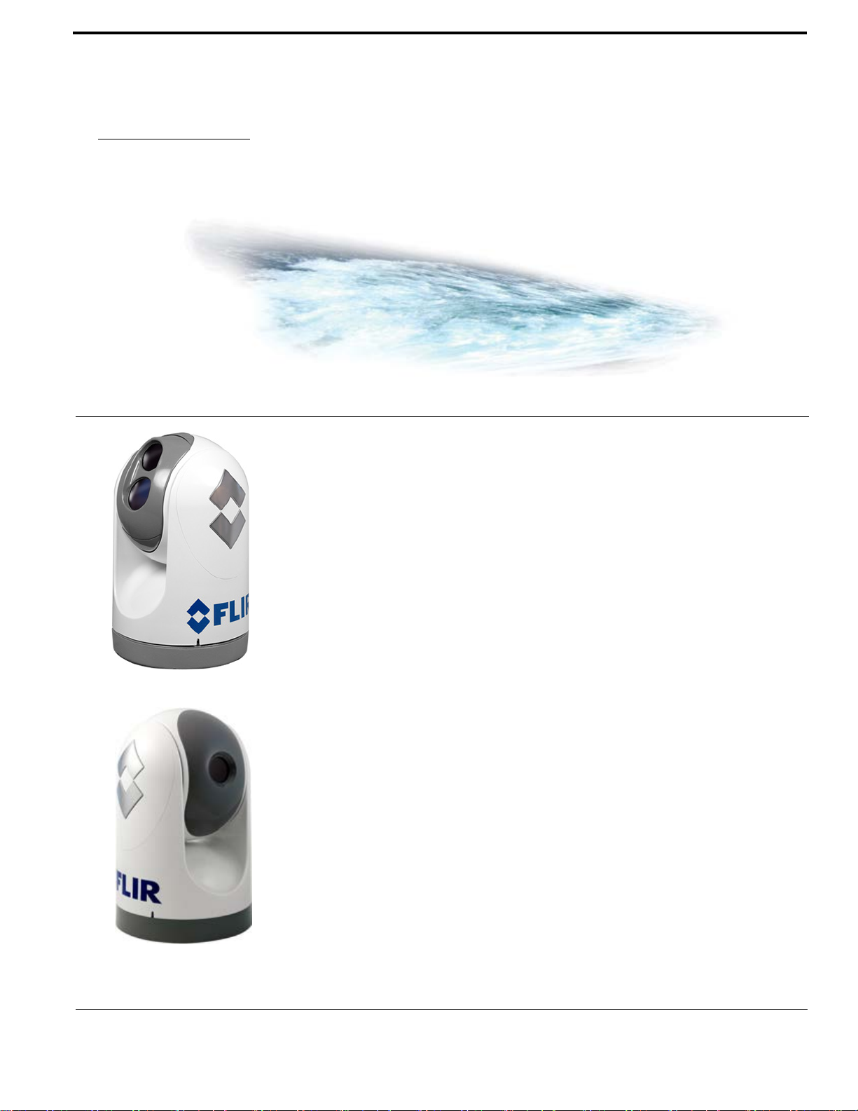
M-Series is a maritime thermal imaging system for use on most types of vessels.
The system is available in two configurations:
• The single payload models have a single thermal imaging camera.
• The dual payload models are equipped with both a thermal imaging camera
and a visible-light (DLTV) camera, either low-light or color.
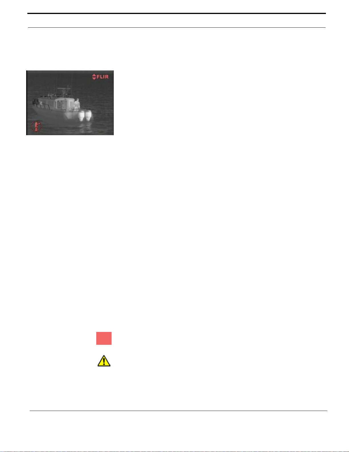
The infrared (IR) thermal camera provides night-time imagery, even in total
darkness, based on temperature differences. The thermal camera provides a
clear video image even under completely dark conditions because it is sensitive
to thermal infrared energy . The infrared camera support s either 2X or both 2X and
4X zoom, depending on the model.
On dual payload models, the two integrated DLTV camera options provide eithe r
black and white imagery in low-light conditions or color imagery. The DLTV
cameras provide enhanced navigational abilities in a variety of conditions, for
example, during twilight hours or when operating along intercoastal waterways
and near harbor entrances. The color camera dual payload model supports
continuous zoom.
One M-Series model (indicated by an S suffix) includes a mechanical stabilization
feature that improves image stability. The stabilization feature compensates for
the motion of the vessel and improves the utility of the camera video output when
operating in rough seas or swell conditions.
For a complete list of models and a comparison of key features, see “Feature
Comparison of M-Series Models” on page 22.
432-0003-00-12 Rev 140 M-Series Installation Guide 3
Page 7
Installing M-Series Systems
www.netzerotools.com
www.netzerotools.com
This manual includes information about the following topics:
• Installation overview
• Mounting the camera and its components
• Connecting the electronics
• Maintaining the camera
• Parts list and other reference information
Additional References
Your M-Series camera comes with a complete documentatio n set on a CD (FLIR
Doc. # 432-0003-00-16) that includes this manual as well as others. All
documents are in PDF format and can be viewed with Adobe Acrobat Reader:
• M-Series Operator’s Manual (FLIR Doc. # 432-0003-00-10) contains
information about how to configure, use, and operate the camera.
• M-Series Quick Start Guide (FLIR Doc. # 432-0003-00-11) is a double-sided
card that shows the functions executed by the various JCU buttons.
• M-Series Interface Control Document (ICD) (FLIR Doc. # 432-0003-00) is an
extensive set of CAD drawings with detailed component dimensions, wiring
schemes, mounting dimensions, and several possible system configurations
using more than one JCU.
This manual frequently refers to the ICD drawings for details during the
installation steps. You should ensure that you have these drawings available
before beginning the install.
The ICD drawings are also available from the FLIR Web site:
http://www.flir.com/cvs/americas/en/maritime/ae/
You may also refer to the Resources Web page for up-to-date documentation:
http://www.flir.com/cvs/americas/en/maritime/resources/
Documentation Conventions
For safety, and to achieve the highest levels of performance from the M-Series
system, always follow the warnings and cautions in this manual when handling
and operating the M-Series camera system.
Warning: Warning notices are used to emphasize that hazardous voltages,
currents, temperatures, or other conditions that could cause personal injury or
death exist with this equipment, or may be associated with its use.
4 432-0003-00-12 Rev 140 — M-Series Installation Guide
Caution: Caution notices are used where equipment might be damaged if care is
not taken or an operation might have an unexpected outcome .
Page 8
Installing M-Series Systems
www.netzerotools.com
www.netzerotools.com
Note: Notes call attention to information that is especially significant to
understanding and operat ing the equipment.
Warnings and Cautions
Warning: Do not use the M-Series imaging system as the primary navigation
system. Use it in conjunction with other navigation aids and a primary manual
navigation system.
Warning: Use of insufficient wire gauge can result in fire.
Caution: Do not open the M-Series camera unit for any reason. Disassembly of
the camera (including removal of the cover) can cause permanent damage and
will void the warranty.
Caution: Be careful not to leave fingerprints on the M-Series camera optics.
Caution: The M-Series requires a power supply of 12 – 24V DC nominal, 5 Amp
maximum. Absolute voltage range: 10 – 32V DC. Operating the camera outside of
the specified input voltage range or the specified operating temperature range
can cause permanent damage.
Caution: During installation, ensure the cables exiting the bottom of the camera
are not in contact with sharp edges, do not bend at sharp ang les, and are not
pinched between the bottom of the camera and the mounting surface. Do not p ull
on the cables with excessive force.
Proper Disposal of Electrical and Electr onic Equipment (EEE): The European
Union (EU) has enacted Waste Electrical and Electronic Equipment Directive
2002/96/EC (WEEE), which aims to prevent EEE waste from arising, to
encourage reuse, recycling, and recovery of EEE waste, and to promote
environmental responsibility.
In accordance with these regulations, all EEE products labeled with the “crossed
out wheeled bin” either on the product itse lf or in the product literature m ust not be
disposed of in regular rubbish bins, mixed with regular household or other
commercial waste, or by other regular municipal waste collection means. In stead,
and in order to prevent possible harm to the environment or human health, all
EEE products (including any cables that came with the product) should be
responsibly discarded or recycled.
To identify a responsible disposal method where you live, please contact your
local waste collection or recycling service, your original place of purchase or
product supplier, or the responsible government author ity in your area. Business
users should contact their supplier or refer to their purchase contract.
432-0003-00-12 Rev 140 — M-Series Installation Guide 5
Page 9
Installing M-Series Systems
Dual Payload
Pan/Tilt Camera
Joystick
Control Unit
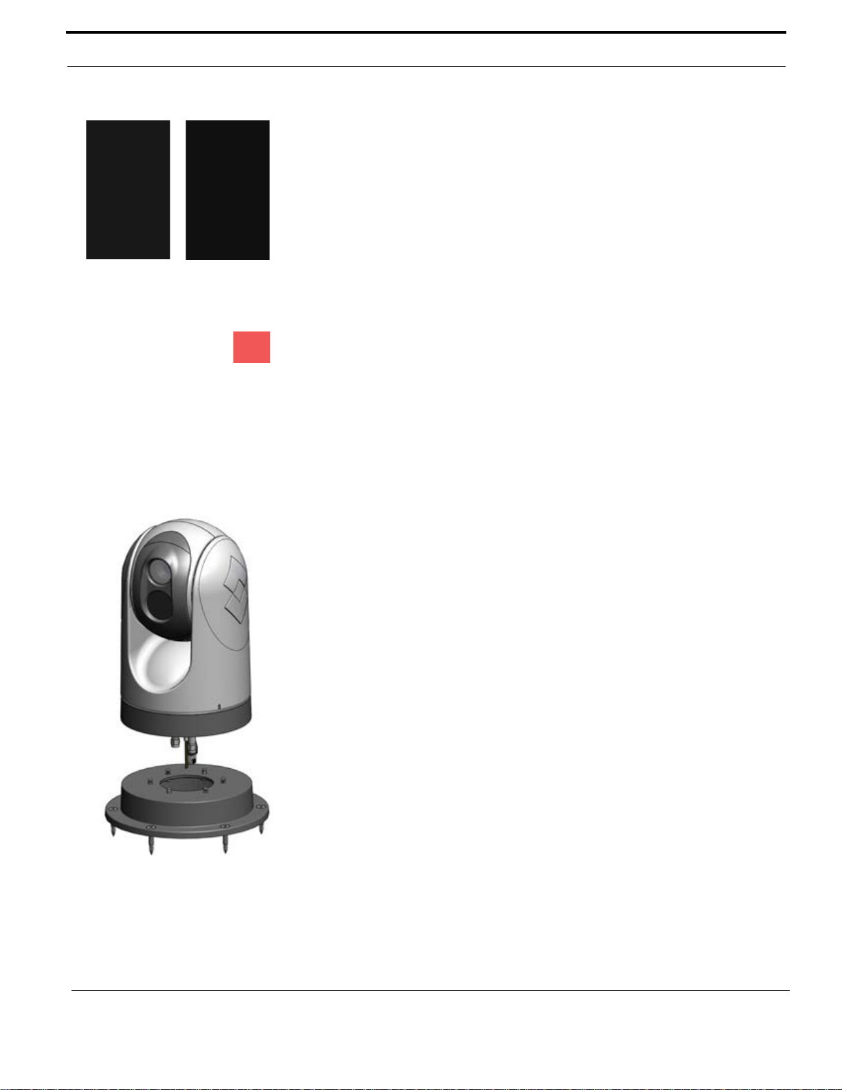
Top-down installation using
mounting plate
www.netzerotools.com
www.netzerotools.com
Installation Overview
The M-Series includes these standard components:
• Pan/tilt camera unit
• Joystick control unit (JCU) and JCU cover
• M-Series documentation package
• 7.7 meter (25-foot) double-shielded Ethernet cable
• Weathertight Ethernet coup ler
• Mounting hardware and connectors
You will need to supply the following items; required lengths vary depending on
your boat's configuration. These items are available in standard le ngths through
FLIR.
• Electrical wire, for system power; up to 30.5 meters (100 feet), 3-conductor,
gauge determined by cable length and supply voltage; see “Electrical
Connections” on page 14 for details.
• Camera grounding strap.
• Up to 2 coaxial RG59/U video cables (with F-style connector at the camera
end).
• Ethernet cables, if required, up to 100 meters (328 feet).
• Miscellaneous electrical hardware, connectors, a nd tools.
The mounting hardware included with the camera includes the following. For
installations with special requirements, you may need to substitute other
mounting hardware:
• Six M6 x 60 stainless steel-th readed studs with washers and nylock nuts or
acorn nuts, for attaching the M-Series camer a body. The length required
depends on the mounting platform thickness. See “Camera Mounting
Options” on page 8 for more details.
• Four captive screws for attaching the JCU.
Optional configurations have additional requirements:
• For a top-down installation, you may need an optional Top-Down Installation
Kit. See “Camera Mounting Options” on page 8 for more information about
mounting kits.
• If you plan to inst all more than one JCU or additional cameras, additional
network hardware (a PoE switch or a non-PoE switch with a PoE injector) is
required. See “Multiple JCU/Camera Installations” on page 10 for more
details.
6 432-0003-00-12 Rev 140 — M-Series Installation Guide
Page 10

Installing M-Series Systems
www.netzerotools.com
www.netzerotools.com
Contact FLIR (phone numbers listed on the back cover of this manual) for more
information regarding available access ories including JCUs, PoE equipment,
video distribution amplifiers, cables, connectors, and mounting hardware.
Installation Planning
You should consider a number of factors in planning the ins tallation of the
M-Series camera and JCU.
General Location Considerations
First determine a good location for mounting the M-Series camera unit and the
JCU. The camera requires at least three connections:
• One for power
• One network connection to the JCU or a PC
• One or two for the video display or disp lays
Optionally, more than one JCU can be used to control the camera and more than
one display can be used to view the video. Also a single JCU can be used to
control more than one camera. Most often, the JCU and the video monitor are
mounted close together, as a pair, so the video can be viewed when the camera
position (pan or tilt) is changed with the JCU.
When determining the component locations, consider how the system may be
expanded in the future. For example, you may want to add an additional monitor,
or perhaps a JCU and monitor pair.
Camera Location Considerations
Consider the following points when determining the camera location:
• Mount the IP66-rated M-Series camera body as high as practical, but without
interfering with any radar , na vigational, or communications electronics. and
minimizing the degree to which vessel structures block the camera’s 360°
view. The camera’s continuous-pan design lets it rotate and point in all
directions. It is good practice to test the unit at the planned installa tion location
with typical vessel electronics active prior to mounting the camera.
• Mount the camera as close to the vessel’s center line as possible so you will
have a symmetrical view of on-coming traffic, obstacles, and other navigational
hazards.
• An appropriate camera mount suited for the camera mass and potential
vibration and mechanical shock is important for proper camera functioning.
The camera is tested to hold position for mechanical shock up to 9g transverse
and 15g vertical. Improper mounts that are loose and/or r esonate can magn ify
432-0003-00-12 Rev 140 — M-Series Installation Guide 7
Page 11
Installing M-Series Systems
Upright
(ball up)
Upside down
(ball down)
Top-down installation
using riser
www.netzerotools.com
www.netzerotools.com
vessel impacts causing the camera to be unable to maintain pointing
direction.
• A final location consideration is the camera’s relation to other navigation
devices. If you are relying on a magnetic compass for navigation and
direction, you should establish a “compass safe distance” for any object
placed in its vicinity, especially any electronic equipment. The magnetic
compass safe distance for the camera is 20 cm (7.9 in).
Camera Mounting Options
Your M-Series camera—except for the M-618CS model—can be installed in an
upright or upside down position.
Warning: The M-618CS model, which is a mechanically stabilized system, must
be installed in the ball-up orientation.
Upright Installation
In most installations, the M-Series is mounted upright on top of a mounting
surface, with the pan/tilt base below the camera; this is known as the ball up
orientation. Optionally, the unit (unless it is the M-618CS model) can be hung
upside down or ball down. Unless otherwise noted, these mounting instructions
assume an upright installation; refer to “Mountin g Upside Down” on page 12 for
information about ball down installations.
Once the mounting location has been selected, verify that both sides of the
mounting surface are accessible. With the supplied hardware, the camera can be
mounted to a platform that is up to 41 mm (1.6”) thick. Depending on the
thickness of the mounting platform, the installer can choose to provide other
mounting hardware, rather than using the supplied threaded studs and nylock/
acorn nuts. The camera mounting surface must be at least as large as the
footprint of the camera itself to ensure an adequate seal with the O-ring.
You do not need to remove the screws in the base of the camera or disasse mble
the camera unit. The camera unit is sealed at the factory. Disassembling the
camera will compromise the seals and will void the warranty.
Top-Down Installation Kits
Generally the M-Series camera is secured directly to a surface using threaded
studs that extend from the base through the mounting plat form and are secured
from below. If it is not possible to access the space belo w the mounting pla t form,
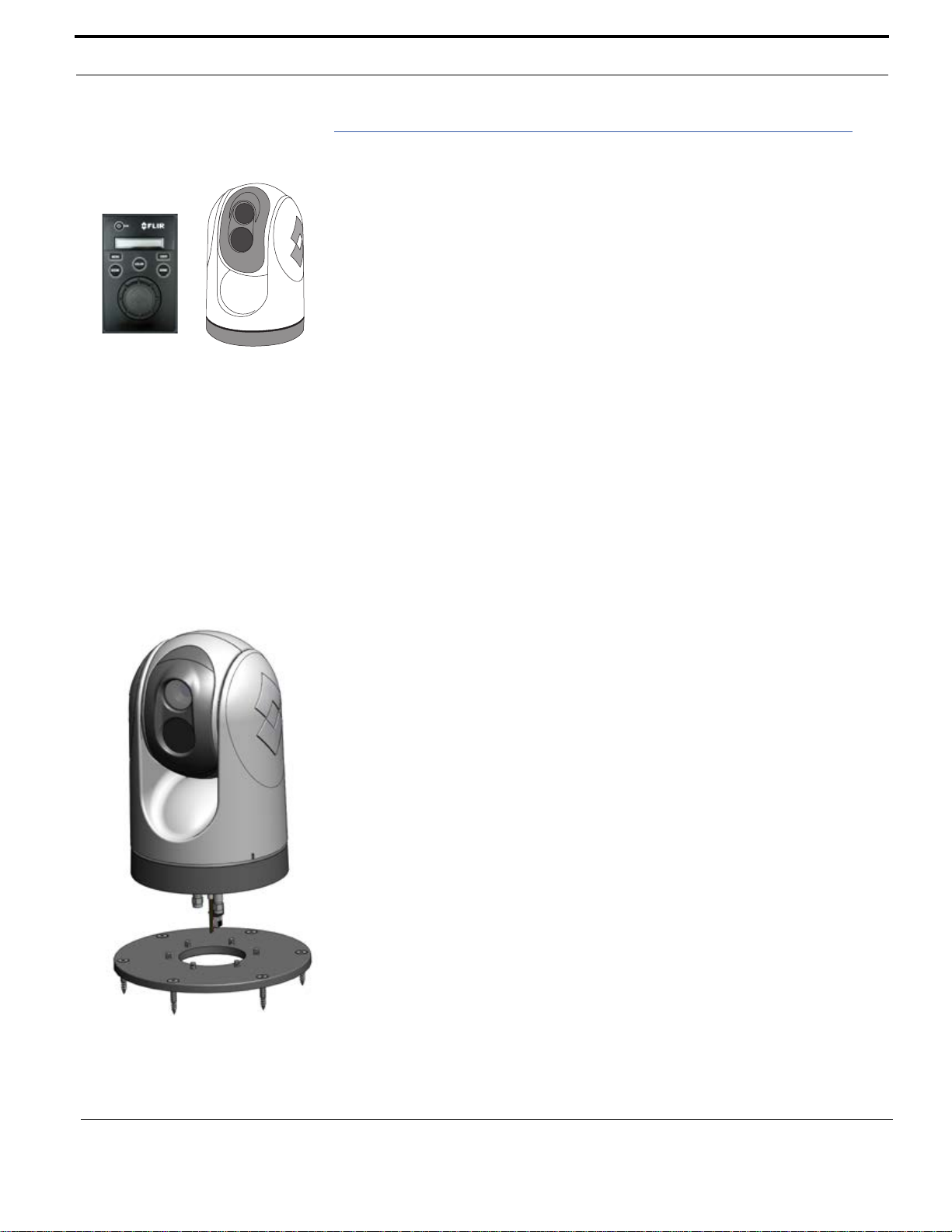
you can mount the camera from above the surface with one of the top-down
mounting accessory kits. This type of installation makes use of either a mounting
plate or mounting riser; these optional accessories are available from FLIR.
To install, the camera is first mounted to the accessory plate or riser, then the
plate or riser is secured to the surface with screws from above. The mounting
riser allows space between the camera base and the mounting surface for the
cable connections. With the mounting plate, the cables pass through the plate
and the connections are below the mounting surface.
8 432-0003-00-12 Rev 140 — M-Series Installation Guide
Page 12
Installing M-Series Systems
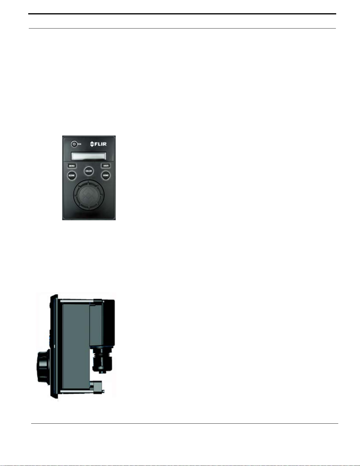
Joystick Control Unit
www.netzerotools.com
www.netzerotools.com
Camera Video Options
The M-Series gimbal assembly has either one or two video cables:
• The cable labeled IR is for the composite—also known as analog—video
signal from the thermal (infrared) camera. This is the only cable on single
payload cameras.
• On dual payload models, the cable labeled VIS/IR is for video from either the
thermal camera or the DLTV camera. You use the JCU to determine which
output displays.
The video from dual payload models can be output on one or two video displays.
If only a single display with a single video input is available, connect the cable
labeled VIS/IR to the display. If the display has more than one video input, both
video cables can be connected to the same display. In this type of installation,
switching between the thermal and visible video channels is performed with the
display controls, rather than the JCU.
Joystick Control Unit (JCU)
Mount the JCU in a convenient area that is close to the monitor being used to
display the M-Series video output. Make sure the area you choose leaves enough
room for the cable under the JCU (refer to the M- Series ICD for d imensions) . The
magnetic compass safe distance for the JCU is 55 cm (21.7 in).
The JCU can be mounted to the dash (or other surface) in any orientation, using
four captive mounting screws that hold panel mounting clamps. When the
mounting screws are tightened, the panel mounting clamps rotate and extend
away from the JCU at a right angle, and come into contact with the mounting
surface. The JCU can be mounted to dash thicknesses ranging from 0.16 – 4.45
cm (0.063 – 1.750 in). A trim bezel snap s on top of the JCU to cover the mounting
screws. See “Installing the Joystick Control Unit (JCU)” on page 12 for detailed
instructions.
JCU Connection to Camera
The JCU is a Power over Ethernet (PoE) device and can be connected to the
camera directly with the included 7.6 meter (25 feet) double-shielded Ethernet
cable or a user-supplied cable of sufficient length. In this case, the JCU draws its
power from the camera.
Alternatively, the camera and the JCU can be connecte d togeth er via an Ethernet
switch; this type of configuration allows more than one JCU or camera to be used.
The JCU draws its power through the Ethernet connection, so a PoE injector or
PoE switch is required.
Prior to Cutting/Drilling Holes
Determine if any interior trim panels must be removed in order to gain access to
the mounting hardware, and remove them ahead of time.
432-0003-00-12 Rev 140 — M-Series Installation Guide 9
Page 13

Installing M-Series Systems
www.netzerotools.com
www.netzerotools.com
When selecting a mounting location for the M-Series, consider cable lengths and
cable routing. Ensure the cables are long enough, given the proposed mounting
locations and cable routing requirements, and route the cables befor e you install
the components.
If you are using one of the top-down installation kits, the riser or plate should be
used as a template for the location of the drill holes and cable access hole.
Caution: When installing the camera, do not tighten the fastener in the threaded
hole so far that it contacts the bottom of the threaded hole. Maximum insertion
should not exceed 6 mm (0.23 in), and torque should not exceed 12 N·m
(8.8 lbf· ft).
Use power cables that have sufficient dimensions to ensure safety and video and
communication cables that have sufficient dimens ions to ensure adequate sign al
strength.
To ensure a proper seal between the camera unit and the vessel, an O-ring
should be installed in the camera base. The O-ring will seal properly with a
surface that is flat to within 0.15 cm (0.06 in) over the diamete r of th e base of the
camera. If it is necessary to install on a surface that does not meet that criteria, a
marine-grade sealant (3M 4200 or equivalent) must be used rather than the
O-ring.
To ensure a proper seal around the JCU, the supplied gasket must be applied to
the JCU and the cutout opening for the JCU should precisely match the template.
If the cutout opening is too large, the gasket around the JCU may not cover the
opening adequately.
Multiple JCU/Camera Installations
In some installations, the system may include additional components, such as
additional cameras or JCUs, video equipment, or ne twork equipment. More than
one JCU can be used to control the camera, and more than one display can be
used to view the video. Also a single JCU can be used to control more than one
camera and optionally you can also use a PC to control the camera.
Refer also to the M-Series ICD (FLIR Doc. # 432-0003-00) for interconnect
diagrams showing several possible system configurations using more than one
JCU.
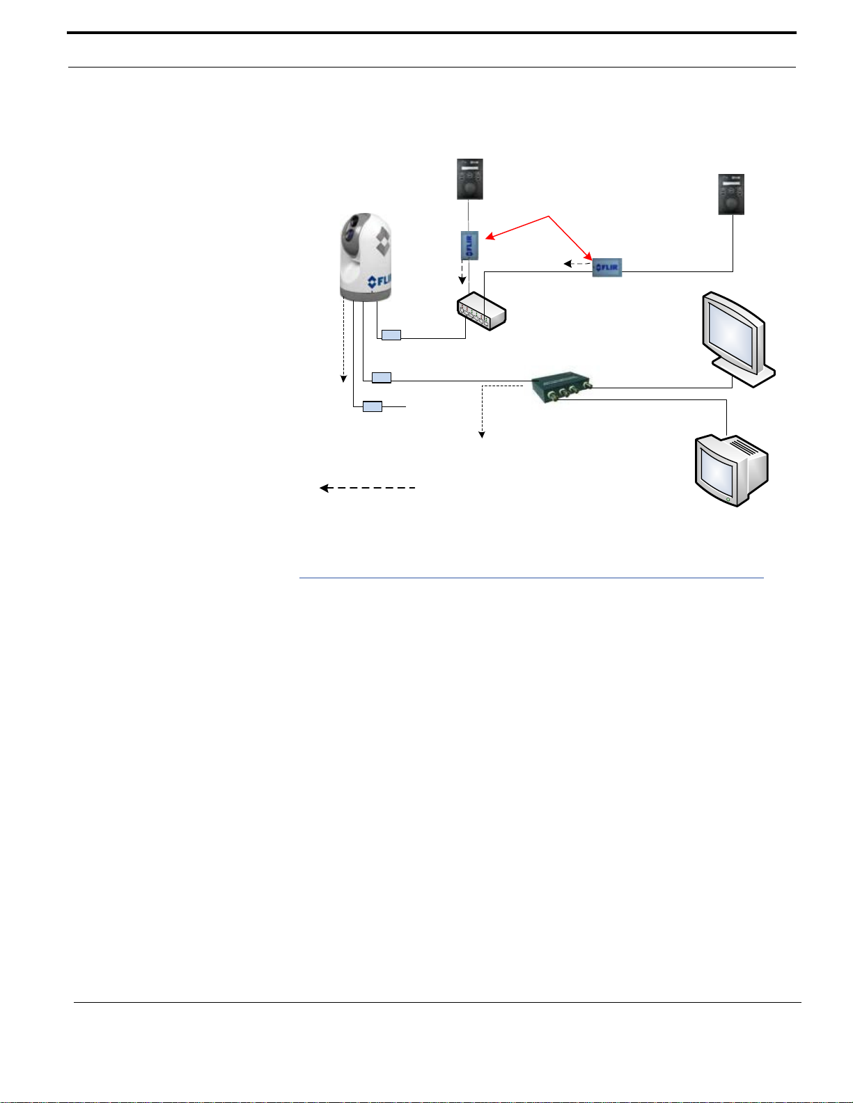
The following diagram shows a possible system configuration using:
• A video amplifier (PN 4108996) supplied by FLIR that supports output to four
video devices
• POE Injectors (PN 4113746) supplied by FLIR for DC/DC Power over
Ethernet
10 432-0003-00-12 Rev 140 — M-Series Installation Guide
Page 14
Installing M-Series Systems
Secondary Video
Primary Video
Ethernet Switch (non PoE)
M-Series Camera
JCU
Video Amplifier
Remote JCU
located with
Remote Monitor
PoE Injectors
Video (IR)
Video (VIS/IR)
Ethernet
Video amplifier
sends the video to
up to 4 monitors
In this example, the IR
video channel is not used
Dashed lines represent
connection to power
(PN 4108996)
(PN 4113746)
www.netzerotools.com
www.netzerotools.com
Physical Installation
Use a thread-locking compound such as Loctite 242 or equivalent with all metalto-metal threaded connections.
Installing the Camera Unit
With the exception of theM-618CS model, which must be installed in the ball-up
orientation, the M-Series camera can be mounted in an upright or upside down
position. Two O-rings are provided for use during the camera installation. You
432-0003-00-12 Rev 140 — M-Series Installation Guide 11
should choose the one most appropriate for your configuration:
• Part # AS568A-427 is typically used for the upright installation. Its dimensions
(in millimeters and inches):
120 mm ID x 7 mm DIA
4.75 in ID x 0.25 in DIA
• Part # A3568A-334 is used for cert ain ball-down inst allations. It s dimensio n (in
millimeters and inches):
67 mm ID x 5 mm DIA
2.63 in ID x 0.19 in DIA
Page 15
Installing M-Series Systems
www.netzerotools.com
www.netzerotools.com
As an alternative to the mounting O-ring, you can use a marine-grade sealant
such as 3M 5200 or the equivalent.
Mounting Upright
Caution: The cable connectors terminating the pigtail cables on the camera are
not sealed connectors; therefore, appropriate sealing steps ar e needed to protect
the connections and the camera.
Caution: Before drilling holes, ensure you have first followed the steps outlined
in the planning section (page 7). For example, it is important to test the unit at the
planned installation location with typical vessel electronics active prior to
mounting the camera.
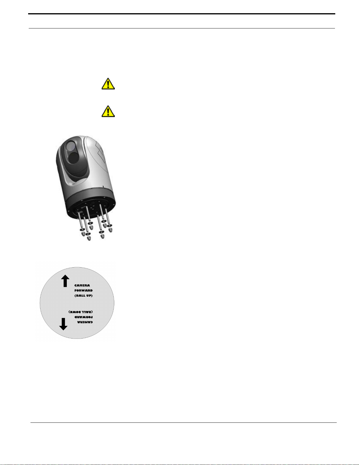
Using the template supplied with the camera as a guide, mark the location of the
holes for mounting the camera. Make sure the template is oriented properly
relative to the bow of the vessel; observe that the forward direction is reversed for
the ball-down installation. If the template is printed, be sure it is printed to scale
so the dimensions are correct. If you are using one of the top-down installation
kits, the riser or plate itself should be used as a template for the location of the
drill holes and cable access hole.
Once the holes are drilled in the mounting surface, install the six (6) threaded
studs into the base of the camera with thread-locking compound. Install the
rubber O-ring in the base of the camera. Thread the power supply, video, and
ethernet cables from the camera through the center hole, and then place the
camera on the mounting surface so the threaded studs extend through the drilled
holes. Then secure the camera body to the mounting surface with the supplied
nuts and washers. As needed, the threaded studs can be replaced with studs of
a different length or cut to a shorter length.
Mounting Upside Down
When the camera unit is mounted in an upside down orient ation—with the ball
down (select models only), you must mount the base rotated 180 degrees
relative to the bow of the vessel, so the internal position sensors are oriented
correctly. Refer to the arrow designation on the bottom of the camera base. A
camera configuration setting accessible through the camera on-screen display
(OSD) menu system is used to configure the camera for the ball-down position.
See the M-Series Operator’s Manual for details.
When the camera is mounted upside down (ball down), the camera base must be
rotated backwards, to point toward the stern of the vessel.
Installing the Joystick Control Unit (JCU)
The cable gland seal is designed for use with double-shielded category 5
Ethernet cable. To ensure a good seal and to maintain compliance with EMI
ratings, a double-shielded cable is required.
12 432-0003-00-12 Rev 140 — M-Series Installation Guide
The JCU enclosure is rated IP66 above the JCU mounting surface/gasket and
rated IP64 behind or below the gasket.
Page 16
Installing M-Series Systems
www.netzerotools.com
www.netzerotools.com
Caution: An installation template is provided in the JCU ICD. If you print the
template from the PDF file, ensure that it was printed to the correct scale by
checking the dimensions prior to cutting any holes.
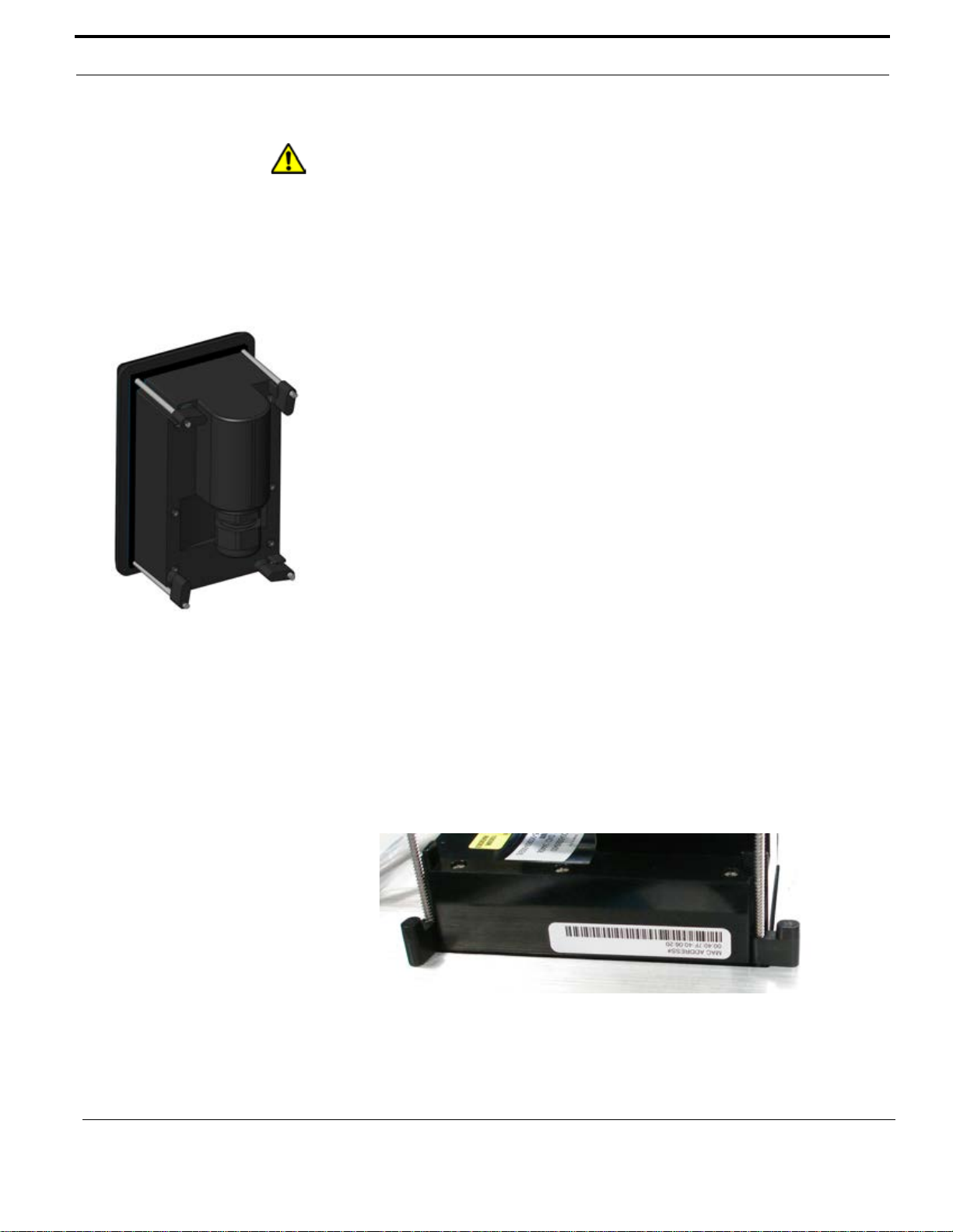
Standard JCU Mounting Instructions
1. Using the JCU template supplied as a guide in Doc. # 500-0385-19, mark the
location of the rectangular opening that will allow the JCU to be recessed in the
vessel’s control console. Ensure the corners are marked precisely and cut
square.
2. Apply the adhesive side of the rubber gasket to the back of the JCU on the
surface that faces the mounting platform. The JCU comes with 4 panel
mounting clamps that can be reversed when the thickness of the panel
material is less than 0.79 cm (5/16 or 0.31 in); see instructions below. Ensure
the mounting clamps are rotated inward and are recessed so the entire JCU
fits into the hole
3. Remove boots from both ends of the Ethernet cable, as it may interfere with
the coupling gland. The boot may cause the RJ45 connector tab to depress,
which can lead to intermittent connections.
4. Loosen or remove the cable gland nut on the JCU, and insert the Ethernet
cable RJ45 connector through the gland nut. Once the Ethernet cable is
connected to the JCU, replace the gland nut and turn the nut 1/4 turn beyond
hand tight.
5. Insert the JCU into the hole and secure by turning the 4 corner screws
clockwise. Rotate each screw one full turn and ensure the mounting clamps
are rotated outward from the JCU housing. Tighten the screws to draw the
mounting clamps up against the mounting surface and then tighten another
quarter or half turn. Do not overtighten the screws.
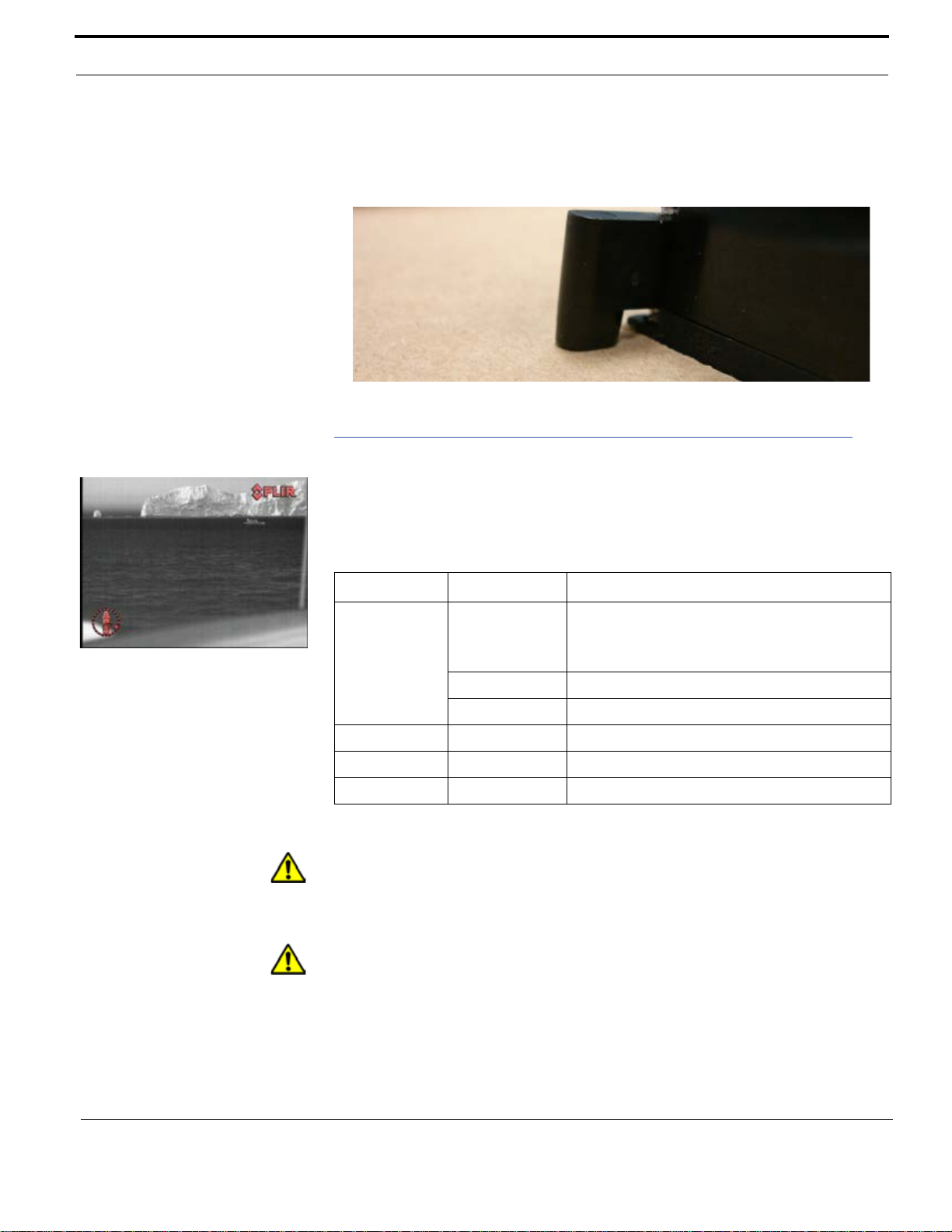
Mounting the JCU to a Thin Panel
As shipped from the factory, the JCU can be mounted to dash thicknesses
ranging from 0.79 – 4.45 cm (0.31 – 1.75 in). The clamps are set with the small
foot on the clamp facing away from the panel and toward the front of the JCU, as
shown below.
432-0003-00-12 Rev 140 — M-Series Installation Guide 13
If you intend to mount the JCU to a panel of 0.79 cm (0.31 in) thickness or less,
remove the clamps from the mounting screws, turn them around and thread them
back onto each of the four screws. In this configuration, the clamp foot faces the
Page 17
Installing M-Series Systems
www.netzerotools.com
www.netzerotools.com
rear of the mounting surface and allows the clamp to contact thinner panel
surfaces while still allowing for proper compression of the JCU mounting gasket
to form a watertight seal.
Electrical Connections
Watertight connectors/enclosures should be used on each of the electrical
connections. Table 1.1 shows the connections for the cables attached to the
camera.
TABLE 1.1 Connections Quick Reference
Cable Label Wire Comment
Power Red Nominal 12V DC / 24V DC
Absolute range 10V to 32V DC
5 AMP maximum
Black DC return
Green Chassis ground
IR F-Style Coax Thermal camera video only
VIS/IR * F-Style Coax Use if only one display
JCU RJ45 Use shielded Ethernet cable
*VIS/IR cable is only available on dual payload models.
Caution: During installation, ensure the cables exiting the bottom of the camera
are not in contact with sharp edges, do not bend at sharp ang les, and are not
pinched between the bottom of the camera and the mounting surface. Do not pull
on the cables with excessive force.
Caution: It is recommended that any built-up triboelectric charg e on the Ethernet
cable should be discharged before connecting it to the JCU and camera. This
can be accomplished simply by pressing an ungloved finger across the Ethernet
RJ45 connector of the cable for a few seconds.
14 432-0003-00-12 Rev 140 — M-Series Installation Guide
Page 18

Installing M-Series Systems
www.netzerotools.com
www.netzerotools.com
Proper Grounding
Caution: Ensure the camera is properly grounded. Following best grounding
practices, the camera chassis ground should use the lowest resistance path
possible.
The green wire in the camera cable can be used to provide chassis ground for
cable lengths under 2 m (6 ft). For longer cabling, the came ra must be connected
to a vessel ground using a low-resistance grounding strap co nnected directly to
one of the M6 mounting bolts on the camera base as shown in the M-Series ICD
(432-0003-00).
Failure to provide this connection may result in electrical interference between
camera and other shipboard electronic systems. Furthermore, it is reco mmended
that a bonded grounding scheme is used with a co mm o n gr ou n d betwe e n the
chassis ground and electrical return, with the connection made as close as
possible to the negative terminal of the battery.
Connecting Power
The camera itself does not have an on/off switch. Generally the M-Series camera
will be connected to a circuit breaker and the circuit breaker will be used to apply
or remove power to the camera. When power is supplied, the camera will be in
one of three modes: Booting Up. Standby, or Powered On. The M-Series
Operator’s Manual has detailed information about powering and operating the
camera.
Consider installing a fuse in line with the power connection to protect the camera
from power surge or short circuit. Table 1.2 applies to both 12V and 24V
operation.
TABLE 1.2 Fuse Recommendations
Model Fuse
M-324L, M-625L, M-612L, M-618CS 5 amp
M-324XP, M-625XP 3 amp
The installer must use power cable wires that are sufficient size gauge or
diameter for the supply voltage and total load (camera and length of cable run), to
ensure proper supply voltage at the camera and adequate current carrying
capacity. Table 1.3 lists recommended wire size for various cable lengths.
TABLE 1.3 Power Cable Wire Gauge Recommendation
Length in Meters (Feet)
8 (25) 16 18
16 (50) 14 18
Wire Gauge (AWG)
for 12V Supply
Wire Gauge (AWG)
for 24V Supply
432-0003-00-12 Rev 140 — M-Series Installation Guide 15
Page 19

Installing M-Series Systems
www.netzerotools.com
www.netzerotools.com
TABLE 1.3 Power Cable Wire Gauge Recommendation
Length in Meters (Feet)
24 (75) 12 16
32 (100) 10 16
Warning: Use of insufficient wire gauge can result in fire. Suggested gauge
depends on supply voltage shown. For lower supply voltages, lower gauge wire
must be used.
Wire Gauge (AWG)
for 12V Supply
Wire Gauge (AWG)
for 24V Supply
Video Connections
The video cables from the camera are terminated with F-type male connecto rs.
Video cables of various lengths with F-type female connectors at one end and
BNC-connectors at the other end are available from FLIR. The video cable used
should be rated as RG59/U or better to ensure an ad equate quality video signal.
Another alternative is to interconnect the camera video cable to a longer video
cable using an optional F-type female-to-female adapto r (FLIR PN 4115330). For
cable runs in excess of 100’, a video amplifier should be used.
Ethernet Connections
The Ethernet cable from the camera can be connected to another Ethernet cable
with the included RJ45 waterproof enclosure connector (FLIR PN 4115028).
The Ethernet network cable should be rated for use with PoE devices
(IEEE802.3af) and should be 8-conductor T568B, Ethernet, double-shielded for
EMI considerations (FLIR PN 308-0163-25 or equivalent).
16 432-0003-00-12 Rev 140 — M-Series Installation Guide
Page 20
CHAPTER 2 M-Series Reference
www.netzerotools.com
www.netzerotools.com
Introduction
This chapter includes the following reference information:
• A summary of maintenance procedures
• A table of camera specifications
• Information about standards referenced during the installation procedure
• A glossary of acronyms
• A table comparing features of various M-Series models
M-Series Maintenance
The M-Series components are designed for ye ars of rugged, trouble-free use.
When the system is not in use, keep the JCU cover in place for additional
protection.
Cleaning the JCU
To clean the JCU, use a soft cloth and clean water. Mild household cleaner such
as Windex can also be used to remove tougher stains or spots. Do not use
alcohol based cleaners or any type of solvent s as this may discolor or damage the
unit.
Cleaning the Camera Optics
Great care should be used with your camera's optics. They are delicate and can
be damaged by improper cleaning. The M-Series thermal camera lenses are
432-0003-00-12 Rev 140 M-Series Installation Guide 17
Page 21
M-Series Reference
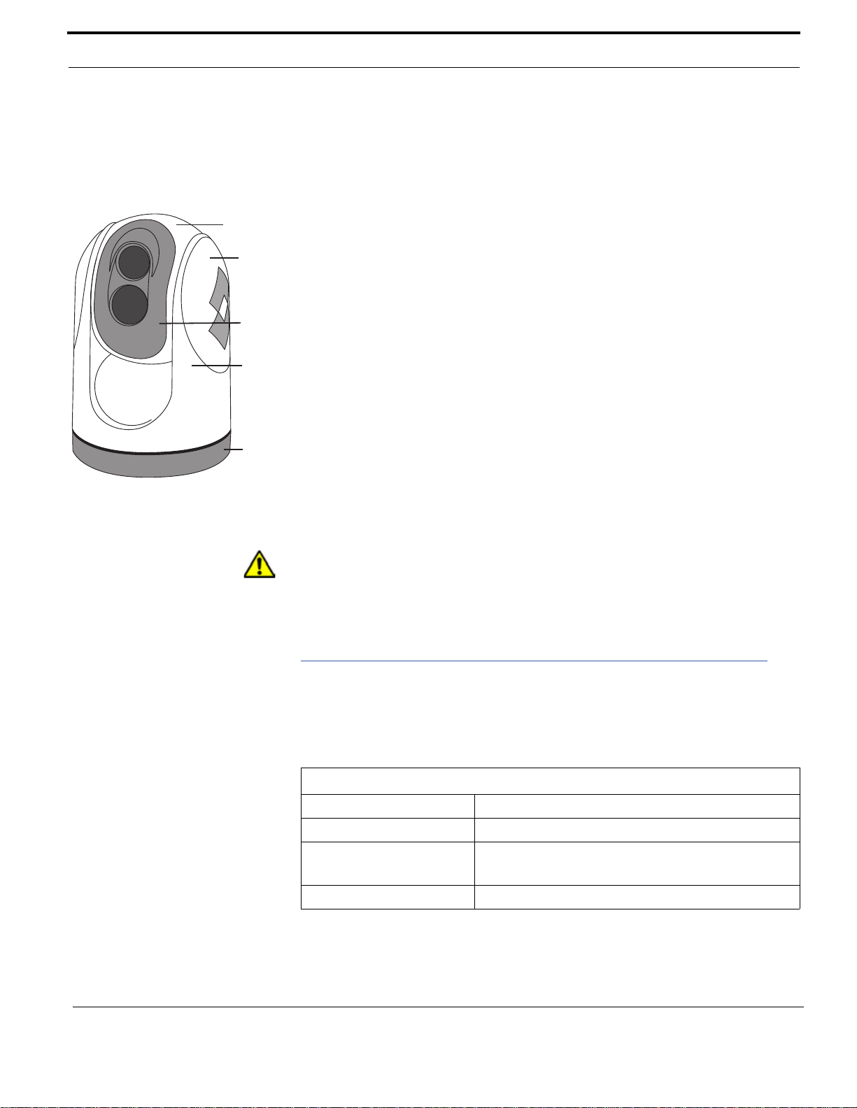
Base
Ball
Side
Cover
Bezel
Yoke
www.netzerotools.com
www.netzerotools.com
designed for the harsh outdoor environment and have a coating for durability and
anti-reflection, but may require cleaning occasionally. FLIR Systems Inc.
suggests that you clean the lens when image quality degrada tion is noticed or
excessive contaminant build-up is seen on the lens.
Rinse the camera housing and optics with low pressure fresh water to remove
any salt deposits and to keep it clean. If the front window of the camera gets
water spots, wipe it with a clean soft cotton cloth dampened with fresh water. If
the window requires further cleaning, use a soft moist cotton-based cloth with
isopropyl alcohol or dish soap.
Do not use abrasive materials, such as paper or scrub br us he s as th is wi ll
possibly damage the lens by scratching it. Only wipe the lens clean when you
can visually see contamination on the surface.
Cleaning the Camera Body
Do not pressure wash the camera, especially around the FLIR logos, as that
could force water through the camera seals. Clean the interface between the
yoke and base often to prevent accumulation of debr is or salt de pos its.
If you have a problem with your thermal camera, do not attempt to repair it
yourself. The M-Series camera is a sealed unit and can not be opened or
serviced in the field. Consult your installation dealer or FLIR Systems Inc. for
repair information.
Caution: The M-Series is sealed at the factory against liquid water, suspended
particulates, and other contaminants. It is important that you not open the camera
for any reason, as it will compromise this seal and possibly damage the unit.
Opening the M-Series camera will void the manufacturer’s warranty.
Specifications
Table 2.1 lists details about physical characteristics, power usage, and
environmental features of your M-Series camera.
TABLE 2.1 Specifications
Physical Characteristics
Camera Size 17.8 cm (7 in) diameter by under 29.2 cm (11.5 in) tall
Camera Weight Under 5.4 kg (12 lb), depending on the camera model
Joystick Size 9.1 X 14.2 X 8.13 cm (3.6 X 5.6 X 3.2 in)
3.17 cm (1.25 in) above platform including joystick
Joystick Weight .45 kg (1 lb)
18 432-0003-00-12 Rev 140 — M-Series Installation Guide
Page 22

M-Series Reference
www.netzerotools.com
www.netzerotools.com
TABLE 2.1 Specifications
Power
Camera Input Power 12 – 24 V DC nominal, 5 A Max
Absolute range 10 – 32V DC
(–10%/+30% per IEC 60945)
Camera Output Power (to
JCU)
JCU Input Power Power over Ethernet (PoE) per IEEE 802.3af
Consumption 25W Nominal
Environmental
Operating temperature
range
Storage temperature range –40º C to +85º C (–38º F to +185º F)
Automatic Window defrost Standard (automatic at unit power-up)
Sand/dust Mil-Std-810E
Automatic Window de-icing Standard (automatic at unit power-up)
Water Ingress IPX 6
Shock 15 g vertical, 9 g horizontal
Vibration IEC 60945; MIL-STD-810E
Lightening Protection Standard
Salt Mist IEC 60945
Wind 100 knot (115.2 mph)
EMI IEC 60945
Power Over Ethernet (PoE) per IEEE 802.3af
48V mode B PoE, RJ45
42W Max (dual payload)
–25° C to +55° C (–11° F to +131° F)
432-0003-00-12 Rev 140 — M-Series Installation Guide 19
External Standards
Table 2.2 lists other sources of information and standards definitions that may be
useful during the installation of your M-Series camera.
TABLE 2.2 External References
Standard Description
ANSI/SCTE 01 2006 “F”
Port, Female, Outdoor
IEC 60169-24 Radio-frequency coaxial connectors with screw coupling,
http://www.scte.org
typically for use in 75 Ohm cable distribution systems
(Type F)
Page 23

M-Series Reference
www.netzerotools.com
www.netzerotools.com
TABLE 2.2 External References
Standard Description
IEC 60945 Maritime navigation and radio communication equipment
and systems general requirements
IEC 60529 Degrees of Protection Provided by Enclosures (IPX6)
IEC 60068 Basic Environmental Testing Procedures, Part 2: Tests
89/336/EEC Electromagnetic Compatibility (EMC) directive
Directive 2002/95/EC Restriction of the use of certain hazardous substances in
electrical and electronic equipment (European Union)
Directive 2002/96/EC Waste Electrical and Electronic Equipment Reg. 2006
TIA/EIA T568B CAT5/RJ-45 wiring standard
IEEE 802.3 / IEEE 802.3u 10Base-T/100Base-TX Ethernet
IEEE 802.3af Power over Ethernet (PoE) standard (48V/400mA/
15.4W)
ANSI/SMPTE 170M - 1994 Composite Analog Video Signal (Supersedes RS-170A)
Directive 96/98/EC Marine Electronics Directive (MED)
Acronyms
The following table lists each acronym that is used in this ma nual and its
meaning.
Acronym/Term Definition
AGC Automatic Gain Control
ANSI American National Standards Institute
API Application Programming Interface
DLTV Daylight TV, used to reference visible-band cameras
EAR Export Administration Regulations
EMI Electromagnetic Interference
FFC Flat Field Correction
FLIR Forward Looking Infrared
FoV Field of View
FPS Frames per Second (refresh rate)
20 432-0003-00-12 Rev 140 — M-Series Installation Guide
HFoV Horizontal Field of View
ICD Interface Control Document
IEC International Electrotechnical Commission
Page 24

M-Series Reference
www.netzerotools.com
www.netzerotools.com
Acronym/Term Definition
IEEE Institute of Electrical and Electronics Engineers
IP Internet Protocol
IR Infrared or thermal
JCU Joystick Control Unit
LCD Liquid Crystal Display
LWIR Long-wave infrared
MFD Multifunction display
NMEA National Marine Electronics Association
NTSC National Television System Committee
PAL Phase Alternating Line
P/T Pan/Tilt
PoE Power over Ethernet
SCTE Society of Cable Telecommunications Engineers
SDK Software Developer’s Kit
UPnP Universal Plug and Play
VDC Volts, Direct Current
VIS Visible (visible-band camera reference)
432-0003-00-12 Rev 140 — M-Series Installation Guide 21
Page 25

M-Series Reference
www.netzerotools.com
www.netzerotools.com
Feature Comparison of M-Series Models
The following table lists each M-Series model and its supported features. Each
model is available in four variations, identified by a unique part number:
• <9 hz thermal frame refresh rate (FPS), NTSC video format
• 30 hz thermal frame refresh rate (F PS), NTSC video format
• <9 hz thermal frame refresh rate (FPS), PAL video format
• 25 hz thermal frame refresh rate (FPS), PAL video format
Note: Different frame formats and rates are used in the US (NTSC, 320 x 240 @
30 FPS) and other parts of the world, such a s Europe and China (PAL, 320 x 256
@ 25 FPS).
22 432-0003-00-12 Rev 140 — M-Series Installation Guide
Page 26

M-Series Reference
Model Part Numbers
Camera
Payload
Video
Format
Thermal
Video
Low-Light
Video (DLTV)
Color Video
(DLTV)
Thermal Video
Resolution
Thermal Frame
Refresh Rate
Mech Image
Stabilization
HFoV
IR Digital
Zoom
M-324XP
432-0003-05-00S Single NTSC Yes No No 320 x 240 <9 Hz No 24° 2x
432-0003-05-00 Single NTSC Yes No No 320 x 240 30 Hz No 24° 2x
432-0003-06-00S Single PAL Yes No No 320 x 256 <9 Hz No 24° 2x
432-0003-06-00 Single PAL Yes No No 320 x 256 25 Hz No 24° 2x
M-625XP
432-0003-09-00S Single NTSC Yes No No 640 x 480 <9 Hz No 25° 2x and 4x
432-0003-09-00 Single NTSC Yes No No 640 x 480 30 Hz No 25° 2x and 4x
432-0003-10-00S Single PAL Yes No No 640 x 512 <9 Hz No 25° 2x and 4x
432-0003-10-00 Single PAL Yes No No 640 x 512 25 Hz No 25° 2x and 4x
M-324L
432-0003-11-00S Dual NTSC Yes Yes No 320 x 240 <9 Hz No 24° 2x
432-0003-11-00 Dual NTSC Yes Yes No 320 x 240 30 Hz No 24° 2x
432-0003-12-00S Dual PAL Yes Yes No 320 x 256 <9 Hz No 24° 2x
432-0003-12-00 Dual PAL Yes Yes No 320 x 256 25 Hz No 24° 2x
M-625L
432-0003-13-00S Dual NTSC Yes Yes No 640 x 480 <9 Hz No 25° 2x and 4x
432-0003-13-00 Dual NTSC Yes Yes No 640 x 480 30 Hz No 25° 2x and 4x
432-0003-14-00S Dual PAL Yes Yes No 640 x 512 <9 Hz No 25° 2x and 4x
432-0003-14-00 Dual PAL Yes Yes No 640 x 512 25 Hz No 25° 2x and 4x
M-612L
432-0003-23-00S Dual NTSC Yes Yes No 640 x 480 <9 Hz No 12° 2x and 4x
432-0003-23-00 Dual NTSC Yes Yes No 640 x 480 30 Hz No 12° 2x and 4x
432-0003-24-00S Dual PAL Yes Yes No 640 x 512 <9 Hz No 12° 2x and 4x
432-0003-24-00 Dual PAL Yes Yes No 640 x 512 25 Hz No 12° 2x and 4x
M-618CS
432-0003-31-00S Dual NTSC Yes No Yes 640 x 480 <9 Hz Yes 18° 2x and 4x
432-0003-31-00 Dual NTSC Yes No Yes 640 x 480 30 Hz Yes 18° 2x and 4x
432-0003-32-00S Dual PAL Yes No Yes 640 x 512 <9 Hz Yes 18° 2x and 4x
432-0003-32-00 Dual PAL Yes No Yes 640 x 512 25 Hz Yes 18° 2x and 4x
www.netzerotools.com
www.netzerotools.com
432-0003-00-12 Rev 140 — M-Series Installation Guide 23
Page 27

M-Series Reference
www.netzerotools.com
www.netzerotools.com
This page is intentionally blank.
24 432-0003-00-12 Rev 140 — M-Series Installation Guide
Page 28

NOTES
www.netzerotools.com
www.netzerotools.com
Page 29

www.netzerotools.com
www.netzerotools.com
 Loading...