

Page 1
ENVIROMUX
®
Series
Temperature/Humidity Sensor Installation
Manual
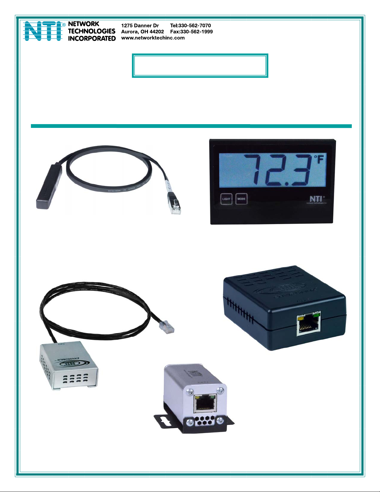
E-STSM-E7, STHSM-E7
Temperature/Humidity Sensors
E-STHS-LCDW
Temperature/Humidity Sensor w/LCD Display
E-STHSB
Temperature/Humidity Sensor
E-STHSB-N4085IND-x
Industrial Temperature/
Humidity Sensor
E-STHS-LSH
Low Self-Heating
Temperature/Humidity Sensor
MAN215 Rev Date 6/21/2019
Page 2

NTI ENVIROMUX TEMPERATURE/HUMIDITY SENSOR ATTACHMENT
TABLE OF CONTENTS
Introduction......................................................................................................................................................................1
Mounting..........................................................................................................................................................................1
E-STHS-LCDW............................................................................................................................................................2
Mounting Instruction .................................................................................................................................................3
Connect Sensors.............................................................................................................................................................4
RJ45 Sensors ..............................................................................................................................................................4
E-STHS-LCDW.........................................................................................................................................................5
RJ45 Sensor Cable....................................................................................................................................................12
TABLE OF FIGURES
Figure 1- Keyhole slot for standard mounting....................................................................................................................................1
Figure 2- DIN rail clip.........................................................................................................................................................................1
Figure 3- Connect Sensors using CAT5 cable with RJ45 connectors................................................................................................4
Figure 4- A portion of the sensor configuration page.........................................................................................................................4
Figure 5- E-STHS-LCDW...................................................................................................................................................................5
i
Page 3
NTI ENVIROMUX TEMPERATURE/HUMIDITY SENSOR ATTACHMENT
INTRODUCTION
Many different sensors can be connected to the ENVIROMUX Series Enterprise Environment Monitoring Systems. Series models
covered by this manual include ENVIROMUX-SEMS-16U and E-16D/5D/2D. A complete listing of available se nsors and
accessories can be found at
http://www.networktechinc.com/enviro-rems.html
http://www.networktechinc.com/environ
http://www.networktechinc.com/environ
http://www.networktechinc.com/environ
covering installation and configuration for all features can also be found at these we bsites.
This manual is only provided to instruct how to install the ENVIROMUX temperature and humidity sensors to these systems.
ment-monitor-16d.html for the E-16D,
ment-monitor-5d.html for the E-5D,
ment-monitor-2d.html for the E-2D, and Manuals for each Environment Monitoring System
for the ENVIROMUX-SEMS-16U,
MOUNTING
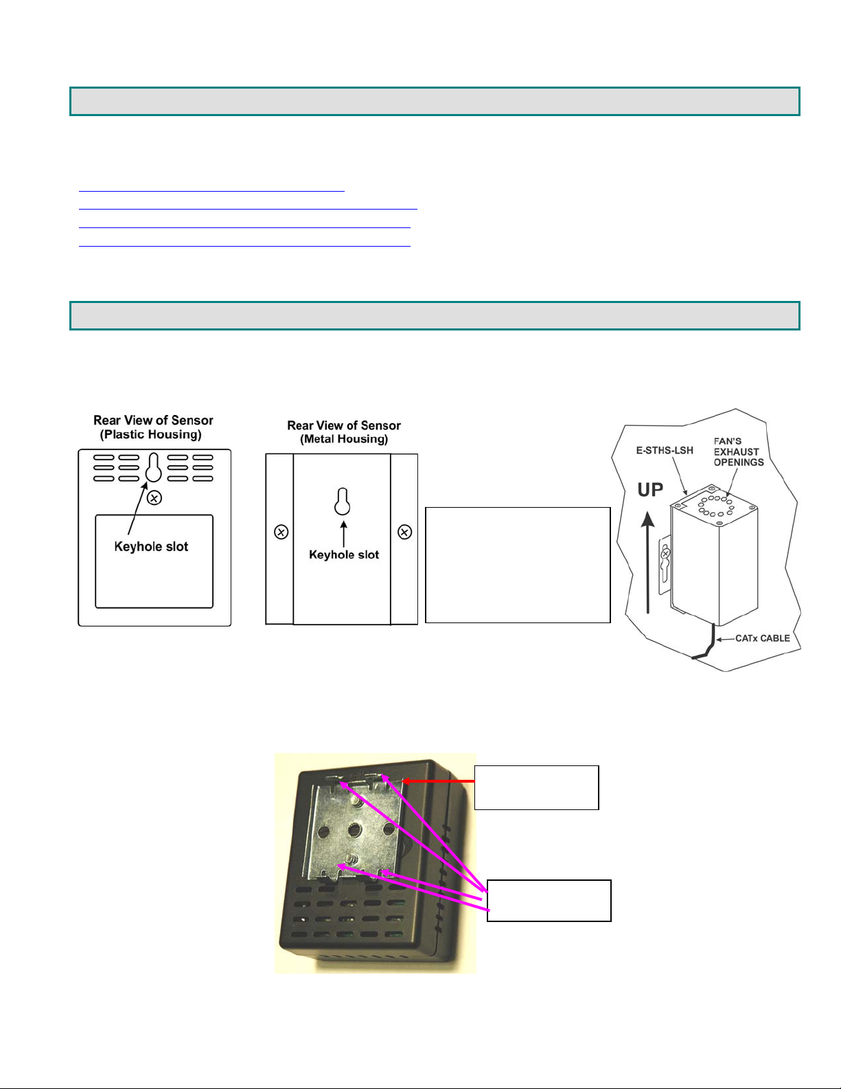
Most of the ENVIROMUX Temperature and Humidity sensors are intended for indoor use only. These sensors can be mounted
in any position but include a keyhole slot on the back to enable quick wall-mounting if desired.
Note: When mounting the ESTHS-LSH Low Self-Heating
Temperature\ Humidity
Sensor, it is best to mount the
sensor vertically with the fan's
exhaust facing up to help to
prevent dust from accreting.
Figure 1- Keyhole slot for standard mounting
If you have purchased an ENVIROMUX Sensor with a DIN rail clip for DIN rail mounting, see the drawing (page 2) for instructions
to install the sensor to the DIN rail.
DIN rail Clip
ears for gripping
the rail
Figure 2- DIN rail clip
1
Page 4
NTI ENVIROMUX TEMPERATURE/HUMIDITY SENSOR ATTACHMENT
E-STHS-LCDW
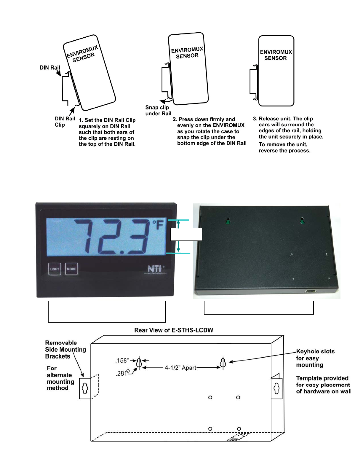
The E-STHS-LCDW is a Temperature and Humidity sensor built into a large wall-mount LCD display with 2” character height for
easy viewing from a distance. There are two key-hole slots on the back, 4-1/2” apart, for hanging the sensor on the wall. A
template has been provided to make placement and hardware location easy. There are also two brackets (with screws) that can
be mounted to the sides. These are provided for an alternate method of mounting.
Frontview of E-STHS-LCDW
(Shown without side mounting brackets)
2” High
Rearview of E-STHS-LCDW
2
Page 5
NTI ENVIROMUX TEMPERATURE/HUMIDITY SENSOR ATTACHMENT
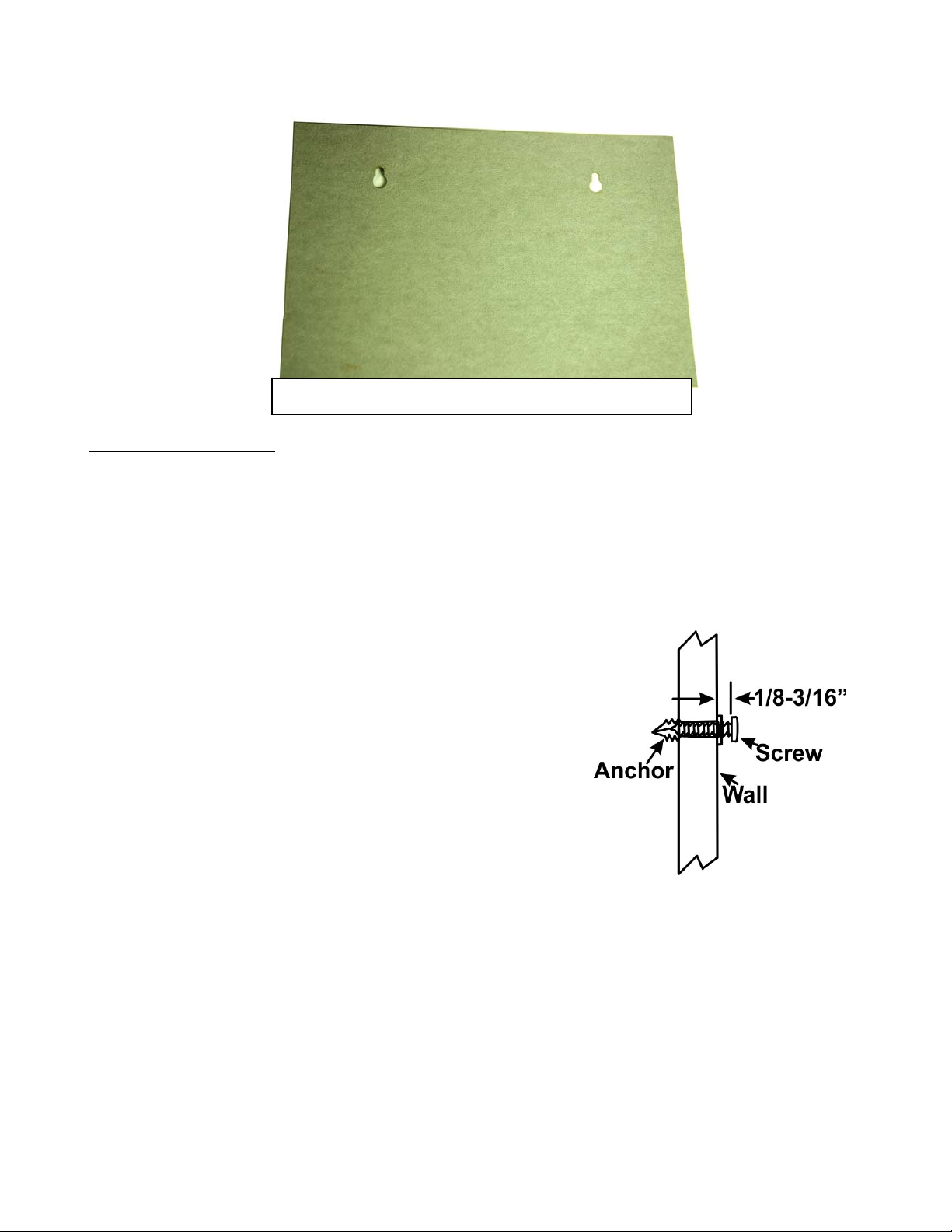
Template for easy mounting the E-STHS-LCDW
Mounting Instruction
Using Side Brackets
1. Mount one side bracket to each side of the sensor with the screws provided.
2. Position sensor and mark top of keyholes.
3. Drill two 3/16” diameter holes where top of keyholes were marked.
4. Insert wall anchors (provided) and start the mounting screws.
5. Hang the sensor on the screws and snug down the screws.
Using Rear Keyhole Slots
1. Position template at mounting location and mark top of keyholes.
2. Drill two 3/16
3. Insert wall anchors (provided) and start the mounting screws.
4. Screw in until head of screw is approximately 1/8-3/16” ” from the wall.
5. Hang the sensor on the screws.
” diameter holes where top of keyholes were marked.
3
Page 6
NTI ENVIROMUX TEMPERATURE/HUMIDITY SENSOR ATTACHMENT
CONNECT SENSORS
RJ45 Sensors
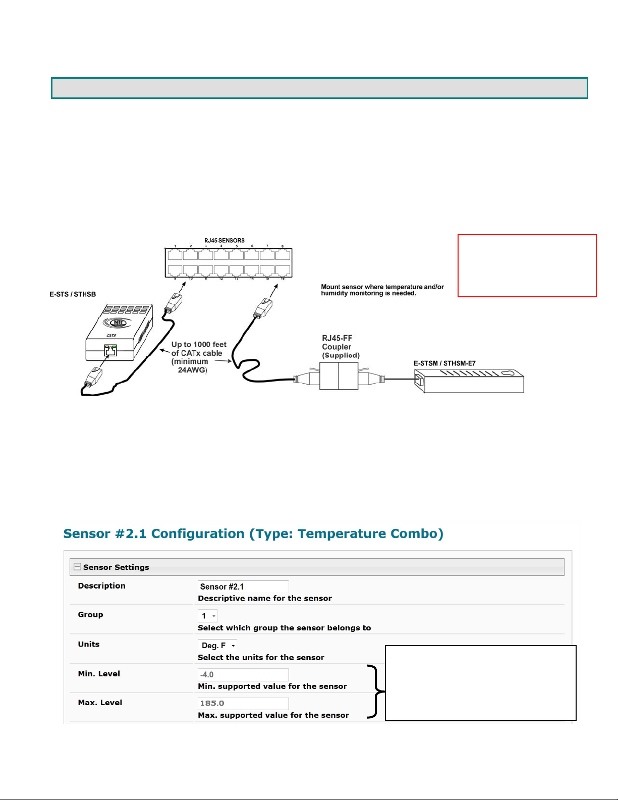
The temperature and humidity sensors for the E-16D/5D/2D and E-SEMS-16(U) Enterprise Environment Monitoring Systems have
RJ45 connection ports. Connect each sensor to one of the female connectors labeled "RJ45 Sensors" on the ENVIROMUX using
CAT5 cable. The male RJ45 connectors should snap into place. (See page 12 for wiring specification an d pinout.) The CAT5
cable that connects the sensor to the ENVIROMUX can be up to 1000 feet in length (except for E-STHS-LCDW, which is limited to
150 feet).
Note: It is very important to locate the temperature and/or humidity sensors away from ventilation so urces and fans.
Note: Shielded CAT5 cable
is required between the
sensor and the ENVIROMUX
to maintain CE compliance
of the sensor.
Figure 3- Connect Sensors using CAT5 cable with RJ45 connectors
Application Note:
When connecting temperature and humidity sensors to the ENVIROMUX, the web interface will identify the sensor accordingly for
the type of sensor it is. The status bar and configuration page will enter the maximum and minimum range that this type of
sensor can display if used with the ENVIROMUX, not necessarily the operating range of the sensor itself. The various
temperature and humidity sensor models offered by NTI have varying ranges of performance capabilities, as indicated in the table
on page 9. Be sure to match the sensor installed to the operating range of the environment it will be expected to work in. Using a
sensor outside of its intended temperature range may result in damage to the sensor.
This is the range the ENVIROMUX will
display, not necessarily the range the
sensor will work within. See
specifications for the sensor being
installed for the proper operating
environment.
Figure 4- A portion of the sensor configuration page
4
Page 7
NTI ENVIROMUX TEMPERATURE/HUMIDITY SENSOR ATTACHMENT
T
D
E-xD firmware version 2.31 or later is required to support this sensor.
E-STHS-LCDW
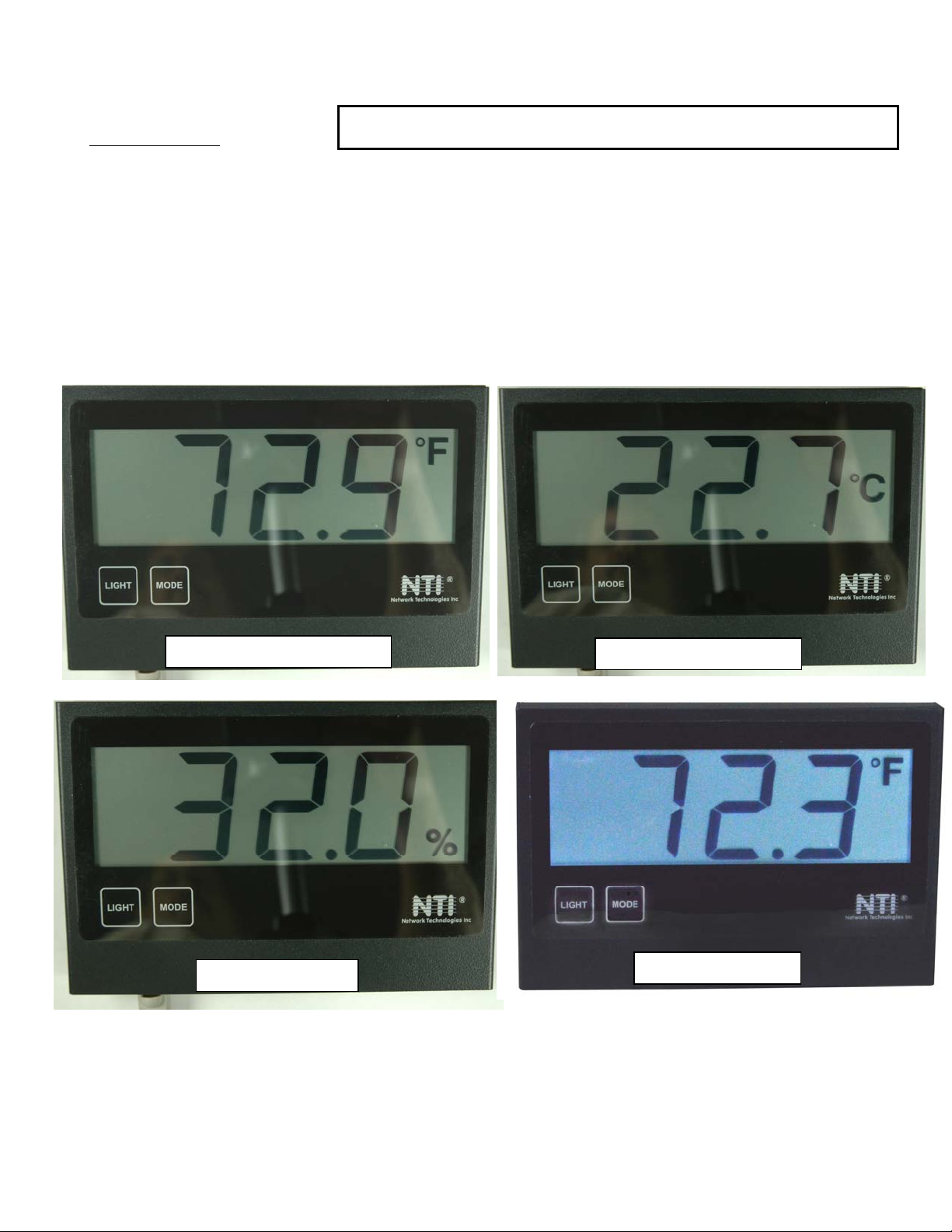
The E-STHS-LCDW is a temperature/humidity sensor with built-in LCD display that has 2” tall characters for easy viewing from
greater distances.
humidity ±4% RH (30°C). It includes two touch-sensitive buttons. One to control the LCD display illumination, and the other to
cycle the display mode between temperature in degrees Fahrenheit, temperature in degrees Celsius, and percentage of humidity.
The E-STHS-LCDW includes slots on the back for hidden mounting hardware and two brackets for alte rnative mounting from the
sides.
To use the MODE button, touch and release to cycle the display from Degrees F. to Degrees C, and to percentage of Humidity,
and once again to return to Degrees F. The display will hold the mode set, each time, until MODE is touched again.
To use the LIGHT button, touch to illuminate the display for 5 seconds. To keep the display illuminated, touch and hold the
LIGHT button for at least 6 seconds. Touch and release again to have illumination stop after 5 more seconds.
. It has a temperature range of -4 to 140°F (-20 to 60°C) ±0.7°F (±0.4°C) and will sense 0 to 90% relative
Temperature in Fahrenheit
Relative Humidity
emperature in Celsius
isplay Illuminated
Figure 5- E-STHS-LCDW
To mount the sensor, use the hardware provided to secure the sensor to the wall (see pages 2- 3). Once it is mounted, connect
a CATx cable between the RJ45 connector and the ENVIROMUX monitoring system.
5
Page 8
NTI ENVIROMUX TEMPERATURE/HUMIDITY SENSOR ATTACHMENT
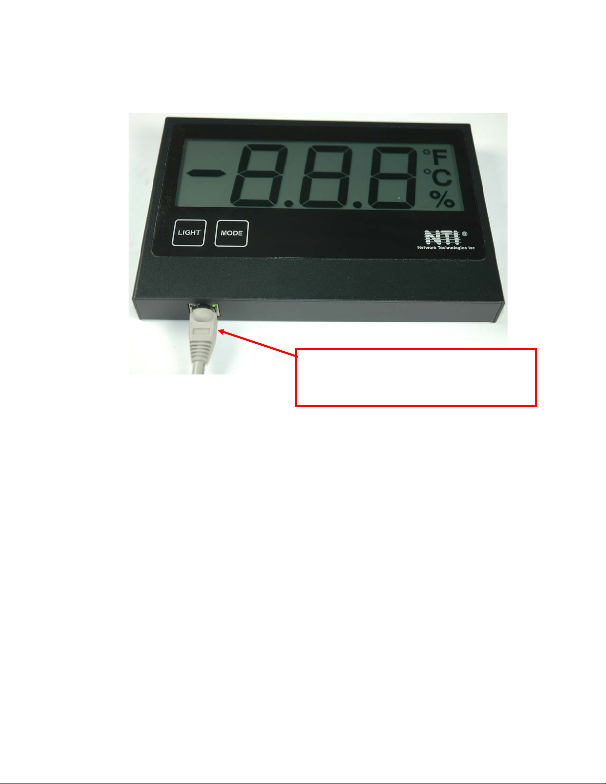
The cable from the ENVIROMUX will attach to the sensor at the RJ45 port on the bottom of the E-STHS-LCDW.
The E-STHS-LCDW will be powered by the ENVIROMUX Monitoring System through the CATx cable. We
recommend using CAT5/5e/6/6a cable (minimum 24 AWG) up to 150 ft (45.7 m) long.
Note: If a longer cable is used (up to 1000ft), the MODE button will not work when the display is illuminated by pressing
the LIGHT button.
Note: The CATx cable from the E-STHS-LCDW to the
E-xD cannot exceed 150ft.
er than 150 foot cable is used, the MODE
If long
button will not function when the backlighting is ON
6
Page 9
NTI ENVIROMUX TEMPERATURE/HUMIDITY SENSOR ATTACHMENT
shielded cable
E-STS-O Outdoor Temperature Sensor
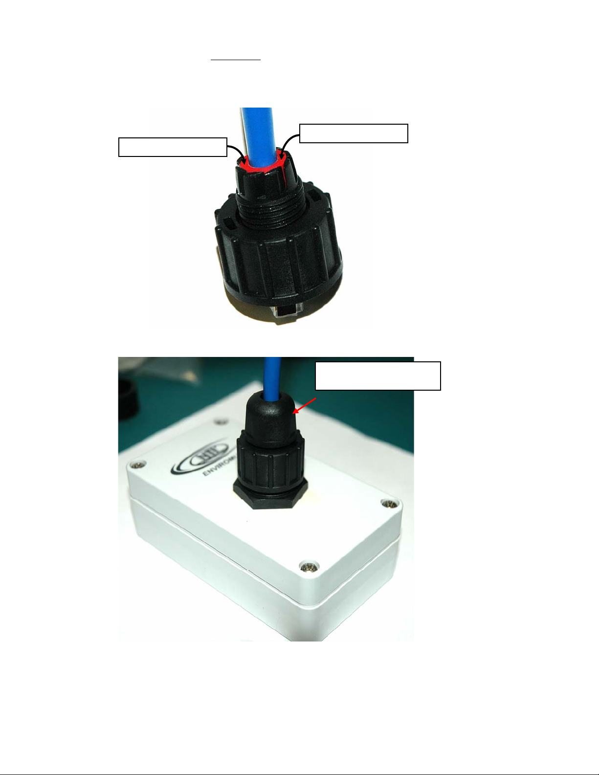
Cable Restraint Assembly Procedure
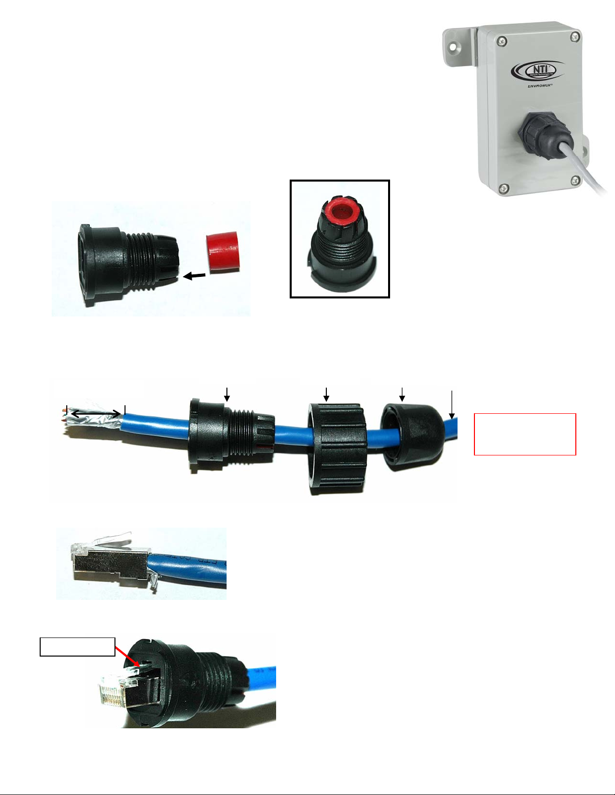
The E-STS-O Outdoor Temperature Sensor includes a water-tight cable
restraint to be applied to the Cat5/5e/6/6a shielded cable to be used to connect the
sensor to an
water-tight upon completion, follow the steps below.
1. Insert the seal ring into the housing.
2. Strip the CATx shielded cable jacket (6mm-7mm O.D.) approximately ½” and insert the cable through the sealing
nut, screw nut, and housing. (Note: Heat shrink tubing can be applied to cable to increase the O.D. of the CATx
cable to 6mm-7mm.)
strip approx. ½”
3. Terminate the CATx shielded cable with an RJ45 conne
4. Set the RJ45 connector into the housing such that the snap handle is in the notch.
Snap handle
E-16D/5D/2D and E-SEMS-16(U) unit. To make sure the connection is
housing
screw nut sealing nut
ctor.
CATx cable
Note: CATx cable
used must be
.
7
Page 10
NTI ENVIROMUX TEMPERATURE/HUMIDITY SENSOR ATTACHMENT
g
5. Make certain that the seal ring is fully-seated
into the housing.
THIS STEP IS EXTREMELY IMPORTANT TO ENSURE A WATER-TIGHT SEAL!
Seal ring fully-seated
Seal ring fully-seated
6. Plug the assembly into the socket on the E-STS-O and secure the screw nut. Then apply the sealing nut and
securely tighten.
Securely tighten sealing
nut to housin
.
8
Page 11
NTI ENVIROMUX TEMPERATURE/HUMIDITY SENSOR ATTACHMENT
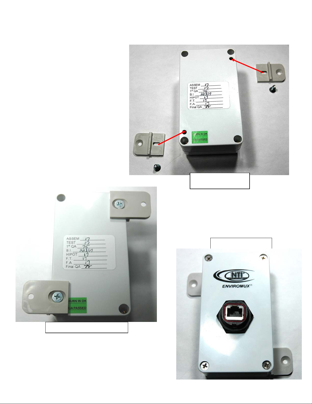
Mounting
To mount the E-STS-O, two brackets have been provided that are each secured with a screw (provided).
Install each bracket with the raised ridge
towards the front of the sensor, so that the
bracket sits flat and squarely against
the sensor case.
Do not overtighten screws or stripping of
the case will occur.
Brackets and screws installed.
Brackets and screws
ready to install.
Sensor ready to mount
9
Page 12

NTI ENVIROMUX TEMPERATURE/HUMIDITY SENSOR ATTACHMENT
TEMPERATURE AND HUMIDITY SENSORS
SENSOR MODEL OPERATING TEMPERATURE
HUMIDITY RANGE ACCURACY
RANGE
E-STS 32 to 122°F (0 to 50°C) n/a ±0.9°F (±0.5°C)
E-STS-O -40°F to 185°F (-40°C to +85°C) n/a ±0.9°F (±0.5°C)
E-STSM-E7 -4 to 140°F (-20 to 60°C) n/a
±1.26°F (±0.70°C) for -4 to
41°F (-20 to 5°C)
±0.72°F (±0.40°C) for 41 to
140°F (5 to 60°C)
E-STHS-LSH -4 to 140°F (-20 to 60°C) 0 to 90% RH
±.90°F (±0.50°C) for -4 to
14°F (-20 to -10°C)
±0.72°F (±0.40°C) for 14 to
140°F (-10 to 60°C)
Inflation due to self-heating
<0.9°F (0.5°C) typical, 2.3°F
(1.3°C) max.
10 to 80% RH, ±3%(30°C)
80 to 90% RH, ±4%(30°C)
E-STHSB
-4 to 185°F (-20 to 85°C)
0 to 80% RH,
±3%(30°C)
±.90°F (±0.50°C) for -4 to
14°F (-20 to -10°C)
80 to 90% RH,
±4%(30°C)
±0.72°F (±0.40°C) for 14 to
185°F (-10 to 85°C)
E-STHSM-E7 -4 to 140°F (-20 to 60°C) 0 to 90% RH
±.90°F (±0.50°C) for -4 to
14°F (-20 to -10°C)
±0.72°F (±0.40°C) for 14 to
140°F (-10 to 60°C)
10 to 80% RH, ±3%(30°C)
80 to 90% RH, ±4%(30°C)
E-STHS-LCD(W) -4 to 140°F (-20 to 60°C) 0 to 90% RH
±.90°F (±0.50°C) for -4 to
14°F (-20 to -10°C)
±0.72°F (±0.40°C) for 14 to
140°F (-10 to 60°C)
10 to 80% RH, ±3%(30°C)
80 to 90% RH, ±4%(30°C)
E-STHS-PRC 32 to 140°F (0 to 60°C) 10% to 80% RH ± 0.4°F(±0.2°C)
± 1.8%RH@86°F (30°C)
E-STSP
-40 to 185°F (-40 to 85°C) n/a ±1.0°F (±0.5°C).
E-STSP-SL-7
Sensor Calibration
All temperature/humidity combination sensors and humidity-only sensors are designed to be accurate within the specifications
stated in the chart above. They are not designed to be re-calibrated. In the event you want the calibration of your sensor to be
checked, please contact NTI for an RMA to return your sensor. Sensor accuracy will be checked for a nominal charge. Sensors
within warranty that are found to be out of factory specification will be repaired or replaced at no additional charge. Normal labor
or replacement charges will apply to sensors out of warranty and out of specification.
Power Consumption
All of our temperature and temperature/humidity sensors operate at 5VDC and draw betwee n 10-56mA (the highest being the ESTHS-LCDW).
10
Page 13

NTI ENVIROMUX TEMPERATURE/HUMIDITY SENSOR ATTACHMENT
Accuracy
The reported accuracy of these sensors is based on an environment of moving air. In a stagnant air environment, the sensor
may read higher than actual temperature.
Coverage
The coverage area for temperature/humidity sensors cannot be specified as there are too many variables that can affect the range
in a sensor's environment.
Behavior
When an E-STHS-xx, E-STHSB or E-STHSM-E7 is connected to an ENVIROMUX system, three sensors values will be reported
for the connected port;
First will be displayed the observed temperature value of the sensor.
Second will be displayed the observed humidity value of the sensor.
Third, is a calculated value using the observed Temp and Humidity values calle d Dew Point. Dew point temperature is
the value where 100% humidity would be achieved. If air and/or surface temperatures are below this value,
condensation will occur.
Dew Point Measurement as it relates to Electronic Equipment
The dew point is the temperature at which air becomes saturated with water vapor.
When further cooled, the airborne water vapor will condense to form liquid water (Dew is an example).
The two primary factors influencing the Dew Point is Temperature and Relative Humidity. As the humidity rises the closer the Dew
Point will be to the current temperature.
In a controlled environment it is important to keep condensation away from electronic equipment. Most electronic equip m ent will
be susceptible to failure in a condensing environment.
Also in very low Dew Point environments static discharge events are more likely to occur, again putting electronic equipment at
risk.
Note: For people, Dew Points higher then 21°C (70°F) and below -22°C (-8°F) are uncomfortable environments.
Warnings and Alerts from the ENVIROMUX
Setting the Dew Point alerts will depend upon the environment that is being monitored.
An example would be an equipment room that normally operates at 21°C (70°F).
It may be desirable to be warned when the Dew Point reaches 19°C (66°F) and alerted when the Dew Point reaches 21°C (70°F)
as condensation would become a high probability.
For low Dew Points, it may be desirable to be warned when the Dew Point reaches -1°C (30°F) and alerted when the Dew Point
reaches -4°C (25°F) as these conditions would be perfect for static discharge events.
11
Page 14

NTI ENVIROMUX TEMPERATURE/HUMIDITY SENSOR ATTACHMENT
RJ45 Sensor Cable
The CAT5 connection cable between the ENVIROMUX and connected external sensors is terminated wi th RJ45 connectors and
must be wired according to the EIA/TIA 568 B industry standard. Wiring is as per the table and drawing below. The sensors
that connect to “RJ45 Sensor” ports (E-16(U)/xD) are all designed to use cables wired to this standard.
1 White/Orange 2
2 Orange 2
3 White/Green 3
4 Blue 1
5 White/Blue 1
6 Green 3
7 White/Brown 4
8 Brown 4
TRADEMARK
ENVIROMUX is a registere
COPYRIGHT
Copyright © 2008, 2019 by Network Technologies Inc. All rights reserved. No part of this publication may be reproduced, stored
in a retrieval system, or transmitted, in any form or by any means, electronic, mechanical, photocopying, recording, or otherwise,
without the prior written consent of Network Technologies Inc, 1275 Danner Drive, Aurora, Ohio 44202.
CHANGES
The material in this guide is for information only and is subject to change without notice. Network Technologies Inc reserves the
right to make changes in the product design without reservation and without notification to its users.
Pin Wire Color Pair
d
trademark of Network Technologies Inc in the U.S. and other countries.
Pair 2 Pair 1
T
1
+
(View Looking into RJ45 Socket)
Pair 3
Pair 4
T
R
R
T
3
2
4
5
-
+
-
+
R
R
T
8
6
7
-
+
-
MAN215 REV 6/21/2019
12
 Loading...