


TS790 / TS900
10-56 Zone Intruder Alarm Control
Panels
POWER |
BUSY |
Engineers menu 1 |
Select Option : |
1 2 3
4 5 6
7 8 9
ENT 0 ESC
A B C
OMIT AREA
1 2 3
4 5 6
7 8 9
ENT 0 ESC
A B C
OMIT AREA
POWER |
BUSY |
POWER |
FUNCTION |
|
||
|
1 |
2 |
3 |
1 |
2 |
3 |
|
4 |
5 |
6 |
4 |
5 |
6 |
|
7 |
8 |
9 |
7 |
8 |
9 |
|
ENT |
0 |
ESC |
ENT |
0 |
ESC |
|
A |
B |
C |
A |
B |
C |
|
|
OMIT AREA |
|
|
OMIT AREA |
|
User Manual
Quick Reference Guide
Full Set |
Enter your passcode |
X X X X |
|
|
|
Part Set |
Enter your passcode |
X X X X |
|
Press A, B or C as required |
A or B or C |
|
|
|
Unset |
Enter your passcode |
X X X X |
|
|
|
Silent Full Set |
Enter your passcode |
X X X X |
|
Press 8 |
8 |
|
|
|
Silent Part Set |
Enter your passcode |
X X X X |
|
Press A, B or C as required |
A or B or C |
|
Press 8 |
8 |
|
|
|
Bell Test |
Enter your passcode |
X X X X |
|
Press [ENT] within 5 secs. |
[ |
|
Press 1 (sounders on) |
1 |
|
Press [ESC] when finished |
] |
|
|
|
Walk Test |
Enter your passcode |
X X X X |
|
Press [ENT] within 5 secs. |
[ |
|
Press 2 |
2 |
|
Conduct Walk Test |
Conduct Walk Test |
|
Press [ESC] when finished |
] |
|
|
|
Remote Reset |
Enter your passcode |
X X X X |
|
Press [ENT] within 5 secs. |
[ |
|
Press 3 |
3 |
|
Contact your central station and quote 4 digit number |
|
|
Enter reply number |
X X X X |
|
Press [ENT] |
[ |
|
|
|
Change Passcode |
Enter your passcode |
X X X X |
|
Press [ENT] within 5 secs. |
[ |
|
Press 4 |
4 |
|
Enter new passcode |
X X X X |
|
Press [ENT]to accept |
[ |
|
Press [ESC] when finished |
] |
|
|
|
Contents
Overview
Introduction. . . . . . . . . . . . . . . . . . . . . . . . . . . . . . . . . . . . . . . . . . . . 1
TS700 Remote Arming Station . . . . . . . . . . . . . . . . . . . . . . . . . . . . . . 2
TS700 LED Remote Keypad. . . . . . . . . . . . . . . . . . . . . . . . . . . . . . . . 2
TS790 Starburst Remote Keypad . . . . . . . . . . . . . . . . . . . . . . . . . . . . 3
TS900 LCD Remote Keypad . . . . . . . . . . . . . . . . . . . . . . . . . . . . . . . 4
Operating The System
Introduction. . . . . . . . . . . . . . . . . . . . . . . . . . . . . . . . . . . . . . . . . . . . 4 User Menus . . . . . . . . . . . . . . . . . . . . . . . . . . . . . . . . . . . . . . . . . . . . 4 Engineer on Site Message. . . . . . . . . . . . . . . . . . . . . . . . . . . . . . . . . 4 Full Setting The System . . . . . . . . . . . . . . . . . . . . . . . . . . . . . . . . . . . 5 Unsetting The System. . . . . . . . . . . . . . . . . . . . . . . . . . . . . . . . . . . . . 6 Part-Setting Using The Part-Set Buttons . . . . . . . . . . . . . . . . . . . . . . . . 7 Part-Setting With Part Set Passcodes . . . . . . . . . . . . . . . . . . . . . . . . . 8 Silent Setting . . . . . . . . . . . . . . . . . . . . . . . . . . . . . . . . . . . . . . . . . . 10 Unsetting After An Alarm . . . . . . . . . . . . . . . . . . . . . . . . . . . . . . . . . 11 Resetting After An Alarm . . . . . . . . . . . . . . . . . . . . . . . . . . . . . . . . . 11 User Reset. . . . . . . . . . . . . . . . . . . . . . . . . . . . . . . . . . . . . . . . . . . 11
Engineer Reset
Remote Reset . . . . . . . . . . . . . . . . . . . . . . . . . . . . . . . . . . . . . . . 12 Setting individual Wards with Standard User Passcodes. . . . . . . . . . 13 Unsetting individual Wards with Standard User Passcodes. . . . . . . . 14 Setting & Unsetting Wards with the Code Set Group Passcodes . . . 16
User Menu 1
Introduction. . . . . . . . . . . . . . . . . . . . . . . . . . . . . . . . . . . . . . . . . . . 17
Bell Test - 1 . . . . . . . . . . . . . . . . . . . . . . . . . . . . . . . . . . . . . . . . . . 18
Walk Test - 2 . . . . . . . . . . . . . . . . . . . . . . . . . . . . . . . . . . . . . . . . . 18
Remote Reset - 3 . . . . . . . . . . . . . . . . . . . . . . . . . . . . . . . . . . . . . 19
Change Passcode - 4 . . . . . . . . . . . . . . . . . . . . . . . . . . . . . . . . . . 19
Enable Chime - 5 . . . . . . . . . . . . . . . . . . . . . . . . . . . . . . . . . . . . . 19
Omit 24 Hour Group - 6. . . . . . . . . . . . . . . . . . . . . . . . . . . . . . . . . 20
Omitting Circuits - 7. . . . . . . . . . . . . . . . . . . . . . . . . . . . . . . . . . . . 20
Silent Set - 8. . . . . . . . . . . . . . . . . . . . . . . . . . . . . . . . . . . . . . . . . . 22
View Activity Count - 9. . . . . . . . . . . . . . . . . . . . . . . . . . . . . . . . . . 22
Full Set and Part-set - 0 A B C . . . . . . . . . . . . . . . . . . . . . . . . . . 22
User Menu 2
Introduction. . . . . . . . . . . . . . . . . . . . . . . . . . . . . . . . . . . . . . . . . . . 23
View Circuits - 1 . . . . . . . . . . . . . . . . . . . . . . . . . . . . . . . . . . . . . . . 24
Set Clock - 2 . . . . . . . . . . . . . . . . . . . . . . . . . . . . . . . . . . . . . . . . . 24
Set Date - 3 . . . . . . . . . . . . . . . . . . . . . . . . . . . . . . . . . . . . . . . . . . 25
Setup Users - 4. . . . . . . . . . . . . . . . . . . . . . . . . . . . . . . . . . . . . . . . 25
Alter Chime Circuits - 5 . . . . . . . . . . . . . . . . . . . . . . . . . . . . . . . . . 28
Alter 24Hr Group - 6. . . . . . . . . . . . . . . . . . . . . . . . . . . . . . . . . . . . 28 Print System Log -7 . . . . . . . . . . . . . . . . . . . . . . . . . . . . . . . . . . . . 29 Configure Wards - 8 . . . . . . . . . . . . . . . . . . . . . . . . . . . . . . . . . . . 30 Viewing the System Log with an LCD Remote Keypad - 9. . . . . . . 31 Viewing The Log With an LED or Starburst Remote Keypad -9 . . . . 31 Remote Call Back - 0 . . . . . . . . . . . . . . . . . . . . . . . . . . . . . . . . . . 33 Initiate Remote Service Call -A . . . . . . . . . . . . . . . . . . . . . . . . . . . 34
User Menu 3
Introduction. . . . . . . . . . . . . . . . . . . . . . . . . . . . . . . . . . . . . . . . . . . 35
Time Switch A, B & C - 1 . . . . . . . . . . . . . . . . . . . . . . . . . . . . . . . . 36


 A B C . . . . . . . . . . . . . . . . . . . . . . 36
Setting The On Times - 1 2 3 . . . . . . . . . . . . . . . . . . . . . 36
Setting The Off Times - 4 5 6 . . . . . . . . . . . . . . . . . . . . . 37
Setting The Days Of Operation -7 8 9 . . . . . . . . . . . . . . 37
Setting The Day -[ . . . . . . . . . . . . . . . . . . . . . . . . . . . . . 38
Manually Switching The Output -0 . . . . . . . . . . . . . . . . . 38
Part Set Groups - 2 . . . . . . . . . . . . . . . . . . . . . . . . . . . . . . . . . . . . 39
Code Set Groups - 3 . . . . . . . . . . . . . . . . . . . . . . . . . . . . . . . . . . . 40
User Names (TS900 Remote Keypads Only) -4 . . . . . . . . . . . . . . . 41
Edit Text For Part Set Groups (TS900 Remote Keypads Only) -5 . . . 41
Edit Circuit Text (TS900 Remote Keypad Only) -6 . . . . . . . . . . . . . . 42
View Inactive Circuits - 0 . . . . . . . . . . . . . . . . . . . . . . . . . . . . . . . . 43
Text Keypad . . . . . . . . . . . . . . . . . . . . . . . . . . . . . . . . . . . . . . . . . . 44
Fault Finding
Display Messages . . . . . . . . . . . . . . . . . . . . . . . . . . . . . . . . . . . . . . 45
Display Messages (Cont.) . . . . . . . . . . . . . . . . . . . . . . . . . . . . . . . . 46
Glossary of Terms . . . . . . . . . . . . . . . . . . . . . . . . . . . . . . . . . . . . . . 47

TS790/TS900 User Manual |
Overview |
Overview
Introduction
The TS790 and TS900 are advanced security alarm control systems using state of the art electronics to provide comprehensive but flexible protection for both domestic and commercial premises. The system comprises of a number of components linked to a central control unit which is concealed from view but accessible for maintenance. The TS790 can monitor from 10 to 16 detection circuits where as the TS900 can monitor a maximum of 56.
Both systems can be operated from up to four remote keypads which may be one of four types. Detection devices such as door contacts or movement sensors are allocated to detection circuits which are identified on the remote keypad displays. All detection circuits may then be allocated to the whole system or grouped into “Wards” (areas) so that access to certain areas can be controlled independently.
A modem can also be connected to the alarm system via the telephone line to allow remote interrogation, programming and resetting of alarms. This feature is known as “Downloading” and is normally performed by the installation company or central station.
Each alarm installation is specific to the site and its occupier and may differ from other TS790/TS900 installations. This manual describes in detail all the functions and procedures available to the user, however, not all these may be relevant to the way your system is set up. To avoid unnecessary operating errors please discuss the details of the alarm system with your installation company before attempting to use it. Also make sure that your installation company completes the system record sheets at the back of this manual and fills in the details required within the section called “Operating The System”.
1

Overview |
TS790/TS900 User Manual |
TS700 Remote Arming Station
The TS700 Remote Arming Station only allows setting and unsetting. The unit has two indicator LED’s (Light Emitting Diodes), “POWER” and “FUNCTION”. The “FUNCTION” LED may be programmed by the installation company to indicate faults or area set etc.
 Function LED
Power LED |
POWER |
FUNCTION |
On = Mains On |
|
|
Flashing = Mains Off |
|
|
|
|
|
|
1 |
|
|
2 |
|
|
|
3 |
|
|
|
|
|
|
|
BELL TEST |
WALK TEST |
|
|
RESET |
||||||||
|
|
|
|
|
|
|
|
|
|
|
|
|
|||
|
|
|
|
4 |
|
|
5 |
|
|
|
6 |
|
|
|
|
|
|
|
NEW CODE |
|
CHIME |
24hr OMIT |
|||||||||
|
|
|
|
|
|
|
|
|
|
|
|
|
|||
|
|
|
|
7 |
|
|
8 |
|
|
|
9 |
|
|
|
|
|
|
|
ZONE OMIT |
|
SILENT |
|
|
|
|
|
|
||||
|
|
|
|
|
|
|
|
|
|
|
|
|
|
|
|
|
|
|
|
ENT |
|
|
0 |
|
|
|
ESC |
|
|
|
|
|
|
|
|
|
|
|
|
|
|
|
|
|
|
|
|
|
|
|
|
|
|
FULL SET |
|
|
|
|
|
|
|||
|
|
|
|
|
|
|
|
|
|
|
|
|
|
|
|
|
|
|
|
A |
|
|
B |
|
|
|
C |
|
|
|
|
|
|
|
|
|
|
OMIT AREA |
|
|
|
|
|
|
|||
|
|
|
|
|
|
|
|
|
|
||||||
|
|
|
|
|
|
|
|
||||||||
Enter button |
|
Part-set buttons Escape button |
|||||||||||||
Figure 1 TS700 Remote Arming Station
TS700 LED Remote Keypad
The TS700 Remote Keypad has a 4 x 7 segment green Light Emitting Diode (LED) display and back-lit tactile rubber keypad. With LED Remote Keypads text cannot be programmed but all other system functions are available.
Power LED |
|
|
|
|
|
|
|
|
Func. |
|
|
|
|
|
|
4 character LED Display |
|||||||||||
|
|
|
|
|
|
|
|
|
|
|
|
|
|
||||||||||||||
On = Mains On |
|
|
|
POWER |
|
|
|
|
|
|
|
|
|
|
|
|
|
|
|
|
|
|
|||||
|
|
|
|
|
|
|
|
|
|
|
|
|
|
|
|
|
|
|
|
|
|
||||||
Flashing = Mains Off |
|
|
|
|
|
|
|
|
|
|
|
|
|
|
|
|
|
|
|
|
|
|
|
|
|
|
|
|
|
|
|
|
|
|
|
|
|
|
|
|
|
|
|
|
|
|
|
|
|
|
|
|
|
||
|
|
|
|
|
|
|
|
|
|
|
|
|
|
|
|
|
|
|
|
|
|
|
|
|
|
|
|
|
|
|
|
|
|
|
|
|
|
|
|
|
|
|
|
|
|
|
|
|
|
|
|
|
|||
|
|
|
|
|
|
|
|
|
|
1 |
|
|
2 |
|
|
|
3 |
|
|
|
|
|
|
|
|
|
|
|
|
|
|
|
|
|
|
|
BELL TEST |
WALK TEST |
|
|
RESET |
|
|
||||||||||||
|
|
|
|
|
|
|
|
|
|
|
|
|
|
|
|
|
|
|
|
|
|
|
|
|
|||
|
|
|
|
|
|
|
|
|
|
4 |
|
|
5 |
|
|
|
6 |
|
|
|
|
|
|
|
|
|
|
|
|
|
|
|
|
|
|
|
NEW CODE |
|
CHIME |
24hr OMIT |
|
|
|||||||||||||
|
|
|
|
|
|
|
|
|
|
|
|
|
|
|
|
|
|
|
|
|
|
|
|
|
|||
|
|
|
|
|
|
|
|
|
|
7 |
|
|
8 |
|
|
|
9 |
|
|
|
|
|
|
|
|
|
|
|
|
|
|
|
|
|
|
|
ZONE OMIT |
|
SILENT |
|
|
|
|
|
|
|
|
|
|
|
|
||||
|
|
|
|
|
|
|
|
|
|
|
|
|
|
|
|
|
|
|
|
|
|
|
|
|
|
|
|
|
|
|
|
|
|
|
|
|
|
ENT |
|
|
0 |
|
|
|
ESC |
|
|
|
|
|
|
|
|
|
|
|
|
|
|
|
|
|
|
|
|
|
|
|
|
|
|
|
|
|
|
|
|
|
|
|
|
|
|
|
|
|
|
|
|
|
|
|
|
|
|
FULL SET |
|
|
|
|
|
|
|
|
|
|
|
|
|||
|
|
|
|
|
|
|
|
|
|
|
|
|
|
|
|
|
|
|
|
|
|
|
|
|
|
|
|
|
|
|
|
|
|
|
|
|
|
A |
|
|
B |
|
|
|
C |
|
|
|
|
|
|
|
|
||
|
|
|
|
|
|
|
|
|
|
|
|
OMIT AREA |
|
|
|
|
|
|
|
|
|
|
|
|
|||
|
|
|
|
|
|
|
|
|
|
|
|
|
|
|
|
|
|
|
|||||||||
|
|
|
|
|
|
|
|
|
|
|
|
|
|
|
|||||||||||||
|
|
|
|
|
|
Enter button |
|
Part-set buttons Escape button |
|||||||||||||||||||
Figure 2 TS700 LED Remote Keypad
2

TS790/TS900 User Manual |
Overview |
TS790 Starburst Remote Keypad
The TS790 Starburst Remote Keypad has a back-lit 8 character Starburst display and back-lit tactile rubber keypad. With Starburst Remote Keypads, text can be programmed but you are limited to 8 characters.
Power LED |
POWER FUNCTION |
On = Mains On |
|
Flashing = Mains Off |
|

 1
1 


 2
2 


 3
3 

8 character Starburst LCD
BELL TEST WALK TEST RESET
|
|
|
|
4 |
|
|
5 |
|
|
|
6 |
|
|
|
|
|
|
|
NEW CODE |
|
CHIME |
24hr OMIT |
|||||||||
|
|
|
|
|
|
|
|
|
|
|
|
|
|||
|
|
|
|
7 |
|
|
8 |
|
|
|
9 |
|
|
|
|
|
|
|
ZONE OMIT |
|
SILENT |
|
|
|
|
|
|
|
|||
|
|
|
|
|
|
|
|
|
|
|
|
|
|
|
|
|
|
|
|
ENT |
|
|
0 |
|
|
|
ESC |
|
|
|
|
|
|
|
|
|
|
|
|
|
|
|
|
|
|
|
|
|
|
|
|
|
|
FULL SET |
|
|
|
|
|
|
|
||
|
|
|
|
|
|
|
|
|
|
|
|
|
|
|
|
|
|
|
|
A |
|
|
B |
|
|
|
C |
|
|
|
|
|
|
|
|
|
|
OMIT AREA |
|
|
|
|
|
|
|
||
|
|
|
|
|
|
|
|
|
|||||||
|
|
|
|
|
|
|
|
|
|
|
|
|
|
|
|
|
|
|
|
|
|
|
|
|
|
|
|
|
|
|
|
Enter button |
|
Part-set buttons Escape button |
|||||||||||||
Figure 3 TS790 Starburst Remote Keypad
TS900 LCD Remote Keypad
The TS900 Remote Keypad has a back-lit Liquid Crystal Display (LCD) and a back-lit tactile rubber keypad. With LCD keypads the circuit text, user names and part-setting information may be custom programmed to make the system easier to operate.
Press ENT to
Select Functions

 1
1 


 2
2 


 3
3 

32 character LCD
BELL TEST WALK TEST RESET
|
|
|
|
4 |
|
|
5 |
|
|
|
6 |
|
|
|
|
|
|
|
NEW CODE |
|
CHIME |
24hr OMIT |
|||||||||
|
|
|
|
|
|
|
|
|
|
|
|
|
|||
|
|
|
|
7 |
|
|
8 |
|
|
|
9 |
|
|
|
|
|
|
|
ZONE OMIT |
|
SILENT |
|
|
|
|
|
|
||||
|
|
|
|
|
|
|
|
|
|
|
|
|
|
|
|
|
|
|
|
ENT |
|
|
0 |
|
|
|
ESC |
|
|
|
|
|
|
|
|
|
|
|
|
|
|
|
|
|
|
|
|
|
|
|
|
|
|
FULL SET |
|
|
|
|
|
|
|||
|
|
|
|
|
|
|
|
|
|
|
|
|
|
|
|
|
|
|
|
A |
|
|
B |
|
|
|
C |
|
|
|
|
|
|
|
|
|
|
OMIT AREA |
|
|
|
|
|
|
|||
|
|
|
|
|
|
|
|
||||||||
|
|
|
|
|
|
|
|
|
|
|
|
|
|
|
|
|
|
|
|
|
|
|
|
|
|
||||||
|
|
|
|
|
|
|
|
||||||||
Enter button |
|
Part-set buttons Escape button |
|||||||||||||
Figure 4 TS900 LCD Remote Keypad
3

Operating The System |
TS790/TS900 User Manual |
Operating The System
Introduction
Initial access to the system is gained by entering a 4 digit passcode. Every time you wish to use the the system your passcode must be entered correctly. If a passcode is repeatedly entered incorrectly a code tamper alarm will be generated.
Up to 31 separate user passcodes are available for operating the system. The master user (user 01) is the person responsible for allocating other users to the system.
Each user (02-31) may be defined for different authorisation levels. See page 25 for full details, the table below shows the code levels and their menu access:
Code level |
User Menu 1 |
User Menu 2 |
|
User Menu 3 |
|
|
|
|
|
Master |
|
* |
|
* |
|
|
|||
Standard |
|
|
|
|
Holiday |
|
|
|
|
Set Only |
|
|
|
|
Reset Only |
Options 1-9 only |
|
|
|
PA Code |
|
|
|
|
Access |
|
Used for access control |
|
|
Full Set Group |
Only allows setting and unsetting of selected wards |
|||
Code Set Group A |
|
|
|
|
Code Set Group B |
|
|
|
|
Code Set Group C |
|
|
|
|
* If the installation company has programmed the master user for limited access, he or she will NOT have access to “User menu 2" options 6 and 8, or any options in ”User menu 3".
User Menus
In general when ever a user passcode is entered the system will enter into a 5 second function mode, if the [ button is pressed during this time “User menu 1" is selected, as a reminder, a brief description of each menu option within ”User menu 1 “ is printed underneath each button on the the remote keypads, e.g., button 1 selects the ”Bell Test" option. If the [ button is not pressed within 5 seconds the system will attempt to full set.
When any of the menu options are selected the user may abandon the function by pressing the ] button. If the ] button is repeatedly pressed whilst one of the user menus is selected, the alarm system will return to the normal “OPEN” condition.
Engineer on Site Message
When the installation engineer attends the site for routine maintenance etc. the remote keypads may show “Engineer on site” (ENG ON SITE), whilst this message is displayed the alarm system remains fully operational. However, before the engineer leaves the site he should ask one of the users to enter their passcode followed by ], this will clear the "Engineer on site” message and return the system to the normal “OPEN” condition.
4

TS790 & TS900 User Manual |
Operating The System |
Full Setting The System
The full setting procedure may be initiated from any remote keypad (if more than one is fitted). Before attempting to full set the alarm system ensure that all movement detectors are unobstructed and all doors, and windows are secure.
The installation company will have set-up your alarm system to full set by one of the following:
- After entering your passcode the alarm system will be full set after the pre-programmed exit timer has expired. The display at step (2) will
|
|
count down the remaining exit time. |
|
|
- After entering your passcode the alarm system will be full set after the |
|
|
|
|
|
|
|
|
Final Exit door is opened and closed. The display at step (2) will show a |
|
|
count of 9999. |
|
|
- After entering your passcode the alarm system will be full set after the |
|
|
Final Exit door is opened and closed, and after pressing the Exit |
|
|
Terminator button (a push button normally mounted outside of the |
|
|
premises). The display at step (2) will show a count of 9999. |
Instant |
- After entering your passcode the alarm system will be full set after 5 |
|
|
|
seconds. |
If an attempt is made to full set the system whilst any circuits are active (such as a door being open) the display at step (2) will indicate the circuit(s) that are in fault and internal sounder generates an interrupted tone. The fault must be cleared before the setting procedure can be completed. If the system is set by "Timed Exit" or "Instant", and the fault is still present at the end of the exit time an internal alarm will be generated. If fitted, the external strobe light will flash indicating that the system has “Failed to set”. To prevent this alarm simply re-enter your passcode before the exit timer expires.
» To full set the system proceed as follows:
1.Enter your passcode X X X X. The display will show:
2.After 5 seconds the exit sounder will start and the display will show:
3.Leave via the prescribed exit route.
4.The system is set when the exit time has expired, on activation of the Final Exit circuit or pressing the Exit Terminator button, as appropriate. The exit sounder will stop and the display will show:
5.After 5 seconds the “SYSTEM SET” message will disappear and the display will show the time, (date and banner text, LCD only) e.g.,
Press ENT to |
|
FUNCTION |
|
Func. |
Select Functions |
|
|
||
|
|
|
|
|
Please Exit Now. |
|
9999 |
|
9999 |
Time left > 9999 |
|
|
||
|
|
|
|
|
SYSTEM SET |
SET |
SET |
05:30 Sun 28 Apr |
ABC SECURITY |
05:30 |
05.30 |
05:30 Sun 28 Apr |
Setting Mode: |
Timed |
Final Exit |
Exit Terminator |
Instant |
Exit Time: |
________________________ |
|
|
|
|
|
|
|
|
5

Operating The System |
TS790 & TS900 User Manual |
Unsetting The System
You can unset the alarm system from any remote keypad.
» To unset your alarm system, proceed as follows:
1.Enter the premises via the prescribed entry route and proceed directly to the remote keypad. The internal sounders generate an interrupted tone. The display will show the remaining entry time, e.g.,
2.Enter your passcode X X X X before the entry timer expires. The internal sounders will stop and the display will show:
3.After 5 seconds the “SYSTEM OPEN” message will disappear and the display will show the time, (date and banner text, LCD only) e.g.,
Enter Your Code Time left > 0025
SYSTEM OPEN
08:30 Sun 28 Apr
ABC SECURITY
08:30 Sun 28 Apr
0025
OPEN
08:30
0025
OPEN
08.30
If you exceed the entry time the alarm system generates a warning from the internal sounders and starts the “Second Entry” timer. If you do not unset the alarm system before the end of the “Second Entry” timer a full alarm condition will occur. If the installation company has set the “Second Entry” timer to zero the full alarm will occur when the first entry timer expires.
If during the entry procedure the user strays from the prescribed entry route and activates a detection circuit a full alarm will occur (internal sounders and external sounders). If the alarm system is fitted with a remote signalling device such as a digicom this will also be triggered and police action will be taken. However, the alarm system may be programmed with an “Entry Abort” feature which will allow a further pre-set time delay to occur if a detection circuit is accidentally triggered during the entry procedure. This will delay the triggering of the remote signalling device and allow the user time to unset the system. The delay is normally set to 90 seconds by your installation company.
Full Set Entry Time: |
__________________ |
Second Entry Time: |
__________________ |
Part-set Entry Time: |
__________________ |
Entry Abort Delay: |
__________________ |
|
|
6
TS790 & TS900 User Manual |
Operating The System |
Part-Setting Using The Part-Set Buttons
The TS790 & TS900 can have up to three pre-defined part-set configurations. Each configuration allows the alarm system to set with one or more wards isolated. Each configuration is then assigned to a part-set button A, B or C, normally this will be done by the installation company at the time of commissioning. However the master user may also configure the part-set buttons, providing the installation company has programmed the alarm system to allow this facility (see “Part Set Groups on page 39).
» To part-set the alarm system, proceed as follows:
1.Enter your passcode X X X X. The display will show:
2.Within 5 seconds press the required part-set button A, B or C, e.g., press A for part-set A. The display will show:
3.The exit sounder will start. If necessary leave the area via the prescribed exit route. The display will show the remaining exit time, e.g.,
4.The system will be part-set when the exit time has expired, on activation of the Final Exit circuit or by pressing the Exit Terminator button, as appropriate. When the system is part-set the display will show the wards that are set and the time, e.g.,
Press ENT to |
|
FUNCTION |
|
Func. |
|
Select Function |
|
|
|
||
|
|
|
|
|
|
Office Area Only |
|
P. SET A |
|
PS.A |
|
Setting the |
|
|
|
|
|
|
|
|
|
|
|
|
|
|
|
|
|
Please Exit Now. |
|
0025 |
|
0025 |
|
Time left > 0025 |
|
|
|
||
|
|
|
|
|
|
Wards set [ A ] |
|
PART SET |
|
P.SET |
|
05:30 Sun 28 Apr |
|
|
|
||
|
|
|
|
|
|
|
|
A |
|
A |
|
|
|
|
|
|
|
|
|
05.30 |
|
05.30 |
|
The text shown on the LCD remote keypads at step (2) may be programmed by the master user (see “Edit Text for Part-Set Groups” on page 41). If the text is not programmed the display will read the default “Part Set group A” for the above example.
If the alarm system has LED remote keypads fitted, the installation company may have programmed the the system so that the alternating displays shown at step (4) only show the time.
Part-Set A: |
_________________________________________________________ |
||||||
Setting Mode: |
Timed |
Final Exit |
|
Exit Terminator |
|
Instant |
|
Part-Set B: |
_________________________________________________________ |
||||||
Setting Mode: |
Timed |
Final Exit |
|
Exit Terminator |
|
Instant |
|
Part-Set C: |
_________________________________________________________ |
||||||
Setting Mode: |
Timed |
Final Exit |
|
Exit Terminator |
|
Instant |
|
|
|
|
|
|
|
|
|
7
Operating The System |
TS790 & TS900 User Manual |
Part-Setting With Part Set Passcodes
Passcode types “Code Set Group A”, “Code Set Group B”, “Code Set Group C”, and the “Full Set Group” enable the user to set and unset only the wards assigned to their “Code Set Group”. The “Code Set Groups” are configured by the master user or installation company (see “Code Set Groups” on page 40).
The following example shows how to set and unset wards A and B using the passcode type “Code Set Group A”. The example first assumes that the alarm system is initially unset.
» To set your area(s) using a “Code Set Group” passcode, proceed as follows:
1. Enter your “Code Set Group” passcode X X X X. The exit sounder will start. If necessary leave the area via the prescribed exit route. The display will show the remaining exit time, e.g.,
Please Exit Now. |
0025 |
0025 |
Time left > 0025 |
2. The system is part-set when the exit time has expired, on activation of the Final Exit circuit or by pressing the Exit Terminator button, as appropriate. When the system has part-set the display will show the wards that are set and the time e.g.,
Wards set [ AB ] 05:30 Sun 28 Apr

 PART SET

AB
05.30
P.SET
AB
05.30
» To unset your area(s), proceed as follows:
1.Enter the area or premises via the prescribed entry route and proceed directly to the remote keypad. The internal sounders generate an interrupted tone. The display will show the remaining entry time, e.g.,
2.Enter your “Code Set Group” passcode X X X X within the entry time. The internal sounders will stop and the display will show:
3.After 5 seconds the “SYSTEM OPEN” message will disappear and the display will show the time, (date and banner text, LCD only) e.g.,
Enter Your Code Time left > 0025
SYSTEM OPEN
08:30 Sun 28 Apr
ABC SECURITY
08:30 Sun 28 Apr
0025
OPEN
08:30
0025
OPEN
08.30
The “Code Set Group” passcodes may be used when the system is fully set. When the passcode is entered only those wards assigned to the “Code Set Group” will be unset.
The following example shows how to unset wards A and B using the passcode type “Code Set Group A”. The example first assumes that the alarm system is initially full set.
8

TS790 & TS900 User Manual |
Operating The System |
Part-Setting With Part Set Passcodes (Cont.)
» To unset your area(s), proceed as follows:
1.Enter the area or premises via the prescribed entry route and proceed directly to the remote keypad. The internal sounders generate an interrupted tone. The display will show how much time you have left e.g.,
2.Enter your “Code Set Group” passcode X X X X within the entry time. The internal sounders will stop and the display will show the wards that have remained set and the time, e.g.,
Enter Your Code |
0025 |
0025 |
Time left > 0025 |
Wards set [S C] |
|
PART SET |
|
P.SET |
09:30 Sun 28 Apr |
|
|
||
|
|
|
|
|
|
|
S C |
|
SC |
|
|
|
|
|
|
|
09.30 |
|
09.30 |
The system may be returned to the full set condition by re-entering the “Code Set Group” passcode and leaving the area or premises via the prescribed exit route. The system may also be fully unset at any time by entering a valid passcode (Master, Standard or Holiday).
Code Set Group A: |
Sets/unsets wards |
S: A: B: C: |
Code Set Group B: |
Sets/unsets wards |
S: A: B: C: |
Code Set Group C: |
Sets/unsets wards |
S: A: B: C: |
Full Set Group: |
Sets/unsets wards |
S: A: B: C: |
|
|
|
9

Operating The System |
TS790 & TS900 User Manual |
Silent Setting
The alarm system may be full or part-set such that the internal sounders are switched off during the exit procedure. However the system will give a short tone at the end of the exit procedure to indicate that the system has successfully set.
» To full set the alarm system silently, proceed as follows:
1.Enter your passcode X X X X. The display will show:
2.Within 5 seconds press 8. The display will show:
3.Leave via the prescribed exit route.
4.The system is full set when the exit time has expired, on activation of the Final Exit circuit or by pressing the Exit Terminator button, as appropriate.
Press ENT to |
|
FUNCTION |
|
Func. |
Select Functions |
|
|
||
|
|
|
|
|
Please Exit Now. |
|
9999 |
|
9999 |
Time left > 9999 |
|
|
||
|
|
|
|
|
» To part-set the alarm system silently, proceed as follows:
1.Enter your passcode X X X X. The display will show:
2.Within 5 seconds press the required part-set button A, B or C, e.g., press A for part-set A then press 8. The display will show:
3.Leave the area or premises via the prescribed exit route.
4.The system is part-set when the exit time has expired, on activation of the Final Exit circuit or by pressing the Exit Terminator button, as appropriate.
Press ENT to |
|
FUNCTION |
|
Func. |
|
Select Function |
|
|
|
||
|
|
|
|
|
|
Office Area Only |
|
P. SET A |
|
PS.A |
|
Setting the |
|
|
|
|
|
|
|
|
|
|
|
10

TS790 & TS900 User Manual |
Operating The System |
Unsetting After An Alarm
If an alarm has occurred whilst the alarm system is full or part-set, the display will indicate the detection circuit that was triggered when the system is unset. Once the cause of the alarm has been established the system must be reset (see “Resetting after an alarm”).
1.Enter the premises or area via the prescribed entry route and proceed directly to the remote keypad. The internal sounders will generate an interrupted tone. The display will show how much time you have left, e.g.,
2.Enter your passcode X X X X within the entry time. The internal sounders will stop and the display will show the detection circuit that caused the alarm, e.g.,
3.Refer to “Resetting after an Alarm”
Enter Your Code |
|
0025 |
|
0025 |
Time left > 0025 |
|
|
||
|
|
|
|
|
ALARM 03 |
|
ALARM 03 |
|
CA.03 |
09:45.59 28/04 |
|
|
||
|
|
|
|
|
Office Detector |
|
OFFICE |
|
|
09:45.59 28/04 |
|
|
|
|
|
|
|
|
|
If “Circuit Text” has been programmed then the display on the LCD and Starburst remote keypads will alternate between the “Circuit number” and the “Circuit Text” at step (2).
Resetting After An Alarm
The installation company will have programmed the system to be either “User Reset”, “Engineer Reset” or “Remote Reset”, consult your installation company if you are not sure.
User Reset
From step (3) of “Unsetting After An Alarm” proceed follows:
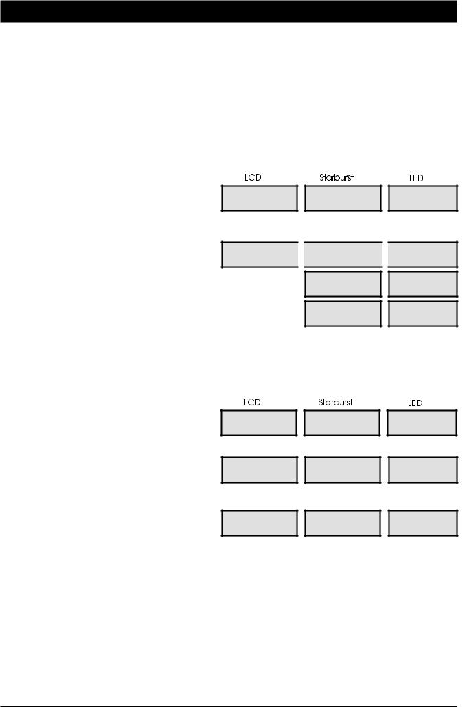
1.Enter your passcode X X X X. The display will show:
2.Within 5 seconds press ]. The display will show:
3.After 5 seconds the “SYSTEM OPEN” message will disappear and the display will show the time, (date and banner text, LCD only) e.g.,
Press ENT to |
|
FUNCTION |
|
Func. |
Select Functions |
|
|
||
|
|
|
|
|
08:30 Sun 28 Apr |
|
OPEN |
|
OPEN |
SYSTEM OPEN |
|
|
|
|
|
|
|
|
|
|
|
|
|
|
ABC Security |
|
08.30 |
|
08.30 |
08:30 Sun 28 Apr |
|
|
Your alarm system is reset by: User: |
Engineer: |
Remote Reset: |
|
|
|
(Continued Over)
11

Operating The System |
TS790 & TS900 User Manual |
Engineer Reset
From step (3) of “Unsetting After An Alarm” proceed as follows:
1.The display will cycle between the detection circuit that caused the alarm and the “CALL ENGINEER TO RESET SYSTEM”. The system will also “beep” every minute to indicate the system requires an engineer to reset the system. To silence the “beeps” simply enter your passcode X X X X.
2.Call the installation company to attend and reset your system.
Tel No._____________________________
|
ALARM 03 |
|
ALARM 03 |
|
CA.03 |
|
09:45.55 28/04 |
|
|
|
|||
|
|
|
|
|
|
|
|
Office Detector |
|
OFFICE |
|
|
|
09:45.55 28/04 |
|
|
|
|
||
|
|
|
|
|
|
|
|
|
|
|
|
|
|
|
CALLENGINEERTO |
|
CALL |
|
CALL |
|
|
RESET SYSTEM |
|
|
|
||
|
|
|
|
|
|
|
|
|
|
ENGINEER |
|
ENG. |
|
|
|
|
|
|
|
|
The display shown at step 2 is programmable and may show something different.
Remote Reset
From step (3) of “Unsetting After An Alarm” proceed as follows:
1. |
Follow Step (1) of the “Engineer Reset” |
|
|
|
|
procedure. |
|
|
|
|
|
2. |
Enter your passcode X X X X. The |
|
|
|
|
Press ENT to |
|
FUNCTION |
|||
display will show: |
Select Functions |
|
|||
|
|
|
|||
3. |
Within 5 seconds press [. “User Menu 1" |
|
|
|
|
User menu 1 |
|
USER 1 |
|||
is selected, the |
display will show: |
Select Option :- |
|
||
|
|
|
|||
|
|
|
|
|
|
4. |
Press 3 to |
select the Remote Reset |
Remote Reset |
|
6846 |
option. The display will show a random four |
Quote > 6846 |
|
|||
|
|
|
|||
digit “Seed Code” e.g., |
|
|
|
||
5. Write down the “Seed Code”. Telephone your central station and quote the “Seed Code”. You will be asked to report the circumstances of the alarm. If an engineer is not required to attend site you will be given a unique four digit “Remote Reset” code.
Func.
1-
6846
Tel No._____________________________
6. Enter the four digit “Remote Reset” code X X X X then press [. A muti-tone beep will confirm acceptance and the display will return to “User Menu 1":
Remote Reset
Reply > - - -
User menu 1 Select Option :-
----
USER 1
----
1-
7.Press ] to return to the Unset condition, the display will show:
8.After 5 seconds the “SYSTEM OPEN” message will
disappear and the display will show the time, (date and banner text, LCD only) e.g.,
SYSTEM OPEN
08:30 Sun 28 Apr
ABC Security
08:30 Sun 28 Apr
OPEN
08.30
OPEN
08.30
12

TS790 & TS900 User Manual |
Operating The System |
Setting individual Wards with Standard User Passcodes
The installation company can enable certain standard users to have access to the “Ward Selection Menu”. This feature allows the user to set individual wards.
» The following example shows how to set wards B and C.
1.Enter your passcode X X X X. The display will show:
2.Select the setting option as follows:
A Part-set A
B Part-set B
CPart-set C
0Ward Selection Menu
NOTE: If an option is not selected after 5 seconds the system will attempt to full set.
3.Press 0 to select the “Ward Selection Menu”. The display will show:
4.Select / de-select the wards by pressing:
A for “Ward A”
B for “Ward B”
C for “Ward C”
0for “Ward S”
e.g., to set wards B and C, de-select wards S and A. The display will show:
5.When the display shows the required wards, press [. The exit sounder will start, if required leave via the prescribed exit route. The display will show the remaining exit time:
6.When exit tone stops the display will show the wards that are set and the e.g.,
Press ENT to |
FUNCTION |
Func. |
Select Functions |
Set -: S A B C |
|
SABC |
|
SABC |
Please Confirm |
|
|
|
|
|
|
|
|
|
Set -: * * B C |
|
--BC |
|
--BC |
Please Confirm |
|
|
|
|
|
|
|
|
|
|
|
|
|
|
Please Exit Now. |
|
0025 |
|
0025 |
Time left > 0025 |
|
|
||
|
|
|
|
|
Wards set [ B C ] |
|
PART SET |
|
P.SET |
05:30 Sun 28 Apr |
|
|
||
|
|
|
|
|
|
|
BC |
|
BC |
|
|
|
|
|
|
|
05.30 |
|
05.30 |
The “Ward Selection Menu” is displayed for a pre-programmed amount of time, which is programmed by the installation company. If no wards are de-selected at the end of the pre-programmed time the alarm system will attempt to full set.
13
 Loading...