

Page 1

Flashlink User Manual
ETH1000MC
Gigabit Ethernet Media
Converter
network-electronics.com
Rev. 6
Page 2

ETH1000MC
1 Revision history
The latest version is always available in pdf-format on our web-site:
http://www.network-electronics.com/
Revision Date Description
6 2007-10-26 New front page and removed old logo.
5 2007-10-05 Added Materials Declaration and EFUP
4 2006-02-22 Reduced maximum optical input power to -6dBm
3 2005-10-25 Added specification for jumbo frames
2 2005-02-21 Completed list of laser options
1 2004-08-10
0 2004-01-30
First version
Initial version
Rev. 6
Network Electronics ASA, P.O.Box 1020, N-3204 Sandefjord, Norway. Tel.: +47 33 48 99 99 - Fax: +47 33 48 99 98
E-mail: [email protected] - Web: http://www.network-electronics.com/
Technical specifications are subject to be changed without notice.
2
Page 3

ETH1000MC
Rev. 6
2 Index
1 Revision history 2
2 Index 3
3 Versions 4
4 Overview 4
5 Specifications 5
6 Laser options 6
7 Connector module 7
8 Status indicators 8
8.1 Front Panel LEDs 8
8.3 Dip switches 9
9 Laser safety precautions 10
10 Declaration of conformity with CE 11
11 General environmental requirements for Network flashlink® equipment 11
12 Product Warranty 12
13 Materials declaration and recycling information 13
14 Materials declaration 13
15 Environmentally-friendly use period 13
16 Recycling information 14
Network Electronics ASA, P.O.Box 1020, N-3204 Sandefjord, Norway. Tel.: +47 33 48 99 99 - Fax: +47 33 48 99 98
E-mail: [email protected] - Web: http://www.network-electronics.com/
Technical specifications are subject to be changed without notice.
3
Page 4
ETH1000MC
Rev. 6
3 Versions
There is only one version of the ETH-1000MC.
4 Overview
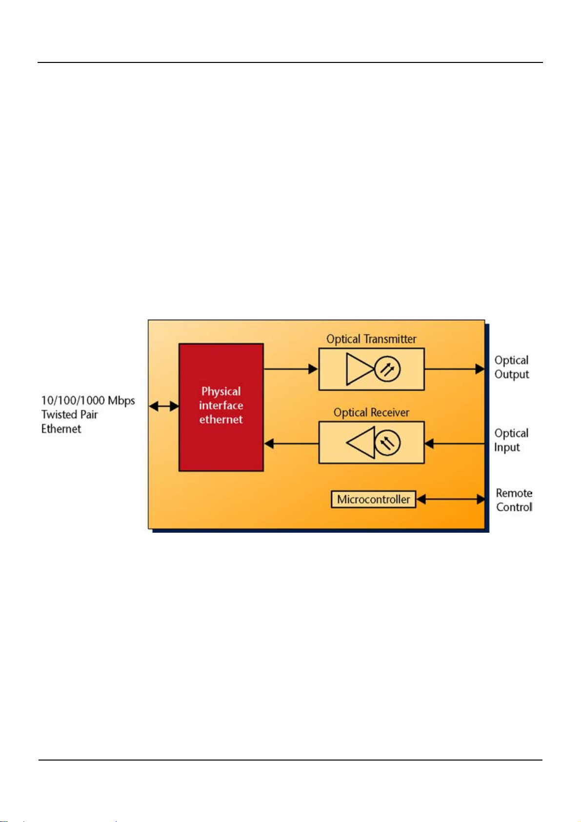
The flashlink ® ETH1000MC is a 1000Base-T to fibre converter module in the Network flashlink family.
The module converts a standard 1000 Mbit/s Ethernet signal on copper to fibre suitable for long haul
applications. The module has one electrical Ethernet port, and one fibre transceiver port (receiver fibre
connector and transmit fibre connector). The speed on the electrical connector is dependent of the DIP
switch setting. Speed will upon link connection automatically be set the highest possible. User can
independently enable or disable 10Mbit, 100Mbit or 1000Mbit. The fibre link can be used in one or two
fibre installations, or occupy two wavelengths in a WDM, CWDM or DWDM installation.
Network Electronics ASA, P.O.Box 1020, N-3204 Sandefjord, Norway. Tel.: +47 33 48 99 99 - Fax: +47 33 48 99 98
E-mail: [email protected] - Web: http://www.network-electronics.com/
Technical specifications are subject to be changed without notice.
4
Page 5

ETH1000MC
Rev. 6
5 Specifications
Optical input:
Sensitivity: Better than –25dBm
Optical wavelength: 1200nm – 1610nm
Transmission circuit fibre: Single mode 9/125um compatible
Return loss: >40dB with single mode fibre
Detector damage threshold: >+1dBm
Max input power: -6 dBm
Connector: SC/UPC
Optical output:
Transmission circuit fibre: Single Mode
Light source: F-P/DFB Laser
Optical wavelength: See Laser Options below
Ethernet:
10BaseT/100BaseTx/1000BaseT on RJ-45 connectors, compliant with IEEE 802.3, IEEE 802.3u and
IEEE 802.3z, speed auto sensing and auto MDI/MDI-X. ETH1000MC supports jumbo frames up to
16000 bytes.
Electrical
Power: +5V DC/2W
Control: Control system for access to setup and module status with BITE
(Built-In Test Equipment)
Network Electronics ASA, P.O.Box 1020, N-3204 Sandefjord, Norway. Tel.: +47 33 48 99 99 - Fax: +47 33 48 99 98
E-mail: [email protected] - Web: http://www.network-electronics.com/
Technical specifications are subject to be changed without notice.
5
Page 6

ETH1000MC
6 Laser options
The ETH1000MC card is available in these versions:
Part number Wavelength Laser type Output power Receiver sensitivity
ETH1000MC-13T, -7.5dBm 1310 ±40 nm Fabry-Perot -7.5 dBm Better than –25 dBm
ETH1000MC-C1270, 0dBm 1270 ±6 nm DFB 0 dBm Better than –25 dBm
ETH1000MC-C1290, 0dBm 1290 ±6 nm DFB 0 dBm Better than –25 dBm
ETH1000MC-C1310, 0dBm 1310 ±6 nm DFB 0 dBm Better than –25 dBm
ETH1000MC-C1330, 0dBm 1330 ±6 nm DFB 0 dBm Better than –25 dBm
ETH1000MC-C1350, 0dBm 1350 ±6 nm DFB 0 dBm Better than –25 dBm
ETH1000MC-C1370, 0dBm 1370 ±6 nm DFB 0 dBm Better than –25 dBm
ETH1000MC-C1390, 0dBm 1390 ±6 nm DFB 0 dBm Better than –25 dBm
ETH1000MC-C1470, 0dBm 1470 ±6 nm DFB 0 dBm Better than –25 dBm
ETH1000MC-C1490, 0dBm 1490 ±6 nm DFB 0 dBm Better than –25 dBm
ETH1000MC-C1510, 0dBm 1510 ±6 nm DFB 0 dBm Better than –25 dBm
ETH1000MC-C1530, 0dBm 1530 ±6 nm DFB 0 dBm Better than –25 dBm
ETH1000MC-C1550, 0dBm 1550 ±6 nm DFB 0 dBm Better than –25 dBm
ETH1000MC-C1570, 0dBm 1570 ±6 nm DFB 0 dBm Better than –25 dBm
ETH1000MC-C1590, 0dBm 1590 ±6 nm DFB 0 dBm Better than –25 dBm
ETH1000MC-C1610, 0dBm 1610 ±6 nm DFB 0 dBm Better than –25 dBm
Rev. 6
Network Electronics ASA, P.O.Box 1020, N-3204 Sandefjord, Norway. Tel.: +47 33 48 99 99 - Fax: +47 33 48 99 98
E-mail: [email protected] - Web: http://www.network-electronics.com/
Technical specifications are subject to be changed without notice.
6
Page 7
ETH1000MC
7 Connector module
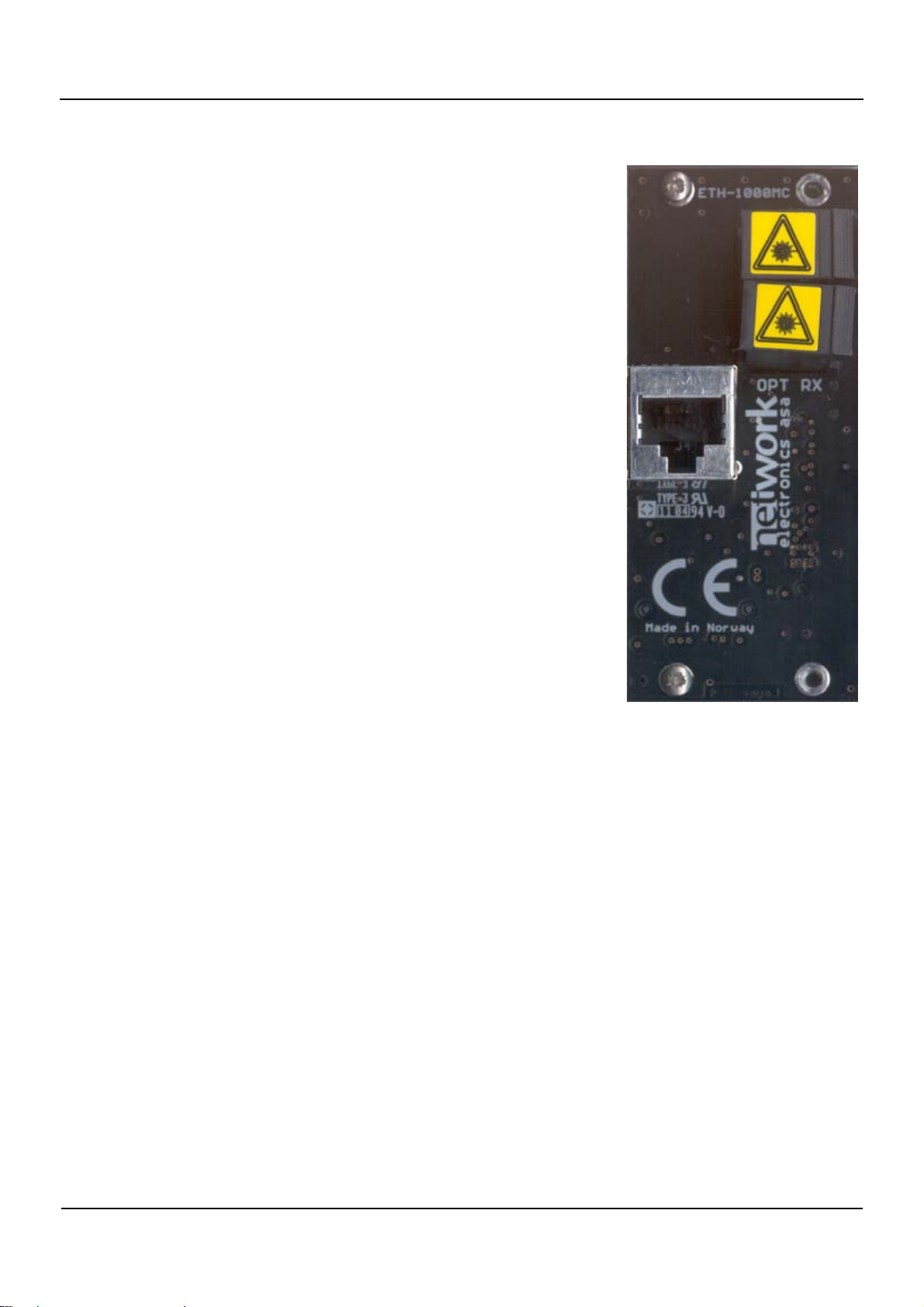
The ETH1000MC has a dedicated connector module:
ETH1000MC-C1. This module is mounted at the rear of the subrack
7.1 Mounting the connector module
The details of how the connector module is mounted, is found in the
user manual for the sub-rack frame FR-2RU-10-2.
This manual is also available from our web site:
http://www.network-electronics.com/
Rev. 6
.
Network Electronics ASA, P.O.Box 1020, N-3204 Sandefjord, Norway. Tel.: +47 33 48 99 99 - Fax: +47 33 48 99 98
E-mail: [email protected] - Web: http://www.network-electronics.com/
Technical specifications are subject to be changed without notice.
7
Page 8
ETH1000MC
8 Status indicators
8.1 Front Panel LEDs
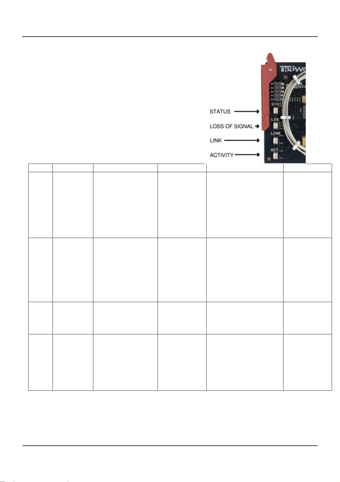
The status of the module can be easily monitored visually by
the LED’s at the front of the module
LED Description Green light Yellow light Red light No light
STAT Module
status
LOS Loss of
optical
signal
LINK Ethernet link Ethernet link to
ACT Ethernet
activity
Module self-test is
OK and power is
present.
Optical input signal
present. Note: This is
an optical
measurement, a green
light does not imply
that there exists a
valid Ethernet signal
on the optical input.
opposite end
established at
1000Mbit
Flashes when
Ethernet packets are
sent over the fibre
link. When the
Ethernet activity is
high, this will be on
continuously.
• Module initialising
(takes approx. 2 sec).
Module has no
power.
• The laser is turned off.
• Module is faulty (fuse
blown, laser failure,
laser APC out of lock,
etc). The card needs
factory repairment.
• No optical input
signal.
• Check fibre
connection.
• Check card in
opposite end.
Ethernet link to
opposite end
established at
Ethernet link to
opposite end
not established.
10 or 100Mbit
The fibre link is
idle, no packets
are sent on the
link.
Rev. 6
Network Electronics ASA, P.O.Box 1020, N-3204 Sandefjord, Norway. Tel.: +47 33 48 99 99 - Fax: +47 33 48 99 98
E-mail: [email protected] - Web: http://www.network-electronics.com/
Technical specifications are subject to be changed without notice.
8
Page 9
ETH1000MC
Rev. 6
8.3 Dip switches
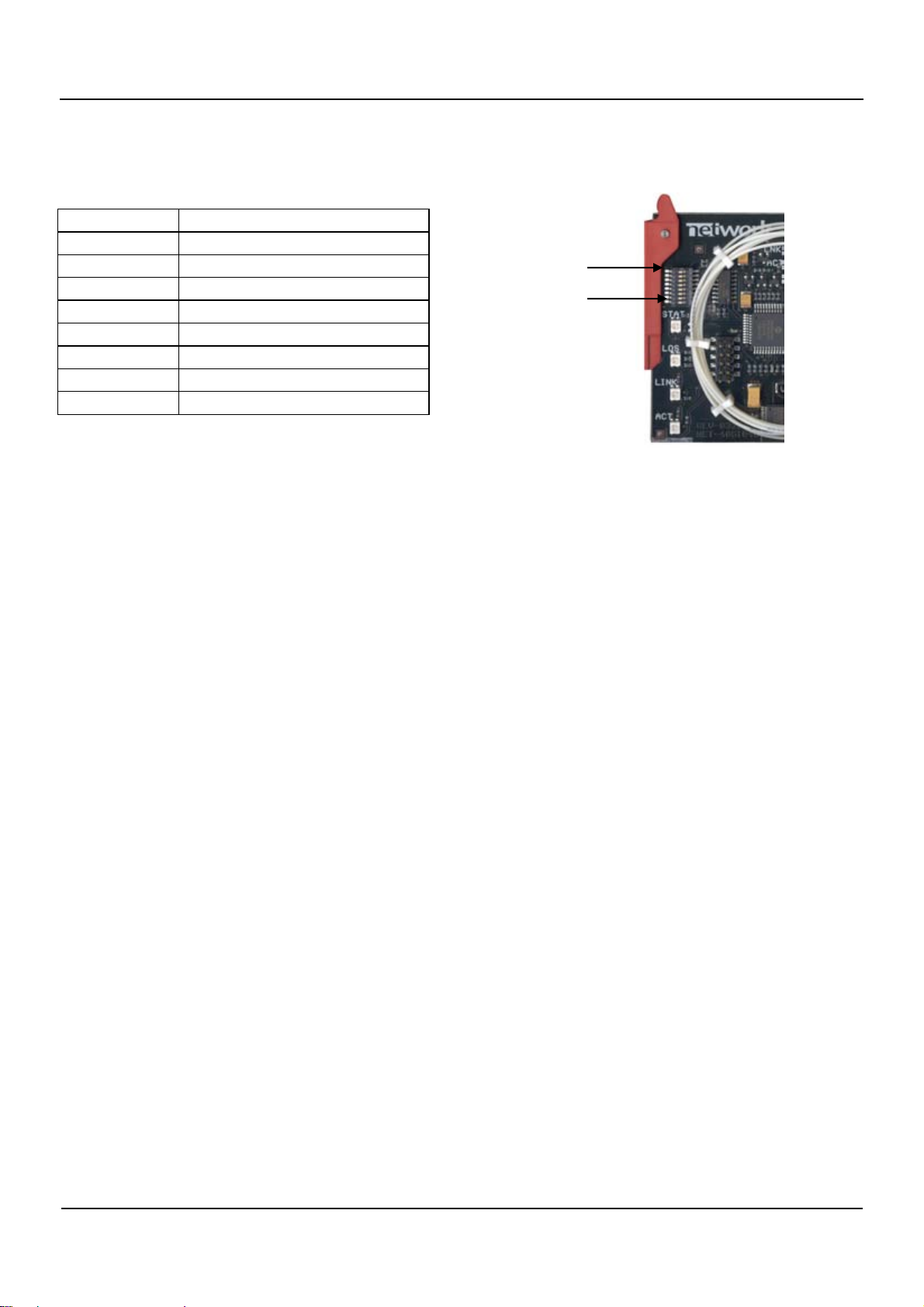
The tables below explains the functionality of the dipswitches shown in the below figure.
Dip switch # Description
1 Enable 10Mbit
2 Enable 100Mbit
3 Enable 1000Mbit (GbE)
4 Reserved
5 Reserved
6 Reserved
7 Reserved
8 Gyda override/DIP
Dip sw # 1
Dip sw # 8
When DIP switch 1,2 and 3 are all on or all off, highest speed possible will be used when link
connection.
Switch 1 disables 10Mbit connection when DIP is closest to board edge. Switch 2 enables/disables
100Mbit and switch 3 enables/disables 1000Mbit.
Dip 4, 5, 6 and 7 are reserved.
Dip 8 sets if Gyda is able to configure or not. When Gyda override is set, the actual setting can be read by
using the info command (se Gyda user manual for details).
Network Electronics ASA, P.O.Box 1020, N-3204 Sandefjord, Norway. Tel.: +47 33 48 99 99 - Fax: +47 33 48 99 98
E-mail: [email protected] - Web: http://www.network-electronics.com/
Technical specifications are subject to be changed without notice.
9
Page 10

ETH1000MC
Rev. 6
9 Laser safety precautions
Guidelines to limit hazards from laser exposure:
Note: All the available EO (including ETH1000MC) units in the flashlink® range include a laser.
Therefore this note on laser safety should be read thoroughly.
The lasers emit light at wavelengths around 1310 nm or 1550 nm. This means that the human eye cannot
see the beam, and the blink reflex cannot protect the eye. (The human eye can see light between 400 nm
to 700 nm).
A laser beam can be harmful to the human eye (depending on laser power and exposure time). Therefore:
!! BE CAREFUL WHEN CONNECTING / DISCONNECTING FIBRE PIGTAILS (ENDS).
NEVER LOOK DIRECTLY INTO THE PIGTAIL OF THE LASER/FIBRE.
NEVER USE MICROSCOPES, MAGNIFYING GLASSES OR EYE LOUPES TO LOOK INTO A
FIBRE END.
USE LASER SAFETY GOGGLES BLOCKING LIGHT AT 1310 nm AND AT 1550 nm
Instruments exist to verify light output power: Power meters, IR-cards etc.
flashlink® features:
All the laser module cards in the flashlink® product range, are Class 1 laser products according to
IEC 825-1 1993, and class I according to 21 CFR 1040.10 when used in normal operation.
More details can be found in the user manual for the FR-2RU-10-2 frame.
*
Maximum output power
: 5 mW.
Operating wavelengths: > 1270 nm.
*
Max power is for safety analysis only and does not represent device performance.
Network Electronics ASA, P.O.Box 1020, N-3204 Sandefjord, Norway. Tel.: +47 33 48 99 99 - Fax: +47 33 48 99 98
E-mail: [email protected] - Web: http://www.network-electronics.com/
Technical specifications are subject to be changed without notice.
10
Page 11

ETH1000MC
Rev. 6
10 Declaration of conformity with CE
This apparatus meets the requirements of EN 55103-1 (November 1996) with regard to emissions, and
EN 55103-2 (November 1996) with regard to immunity; it thereby complies with the Electromagnetic
Compatibility Directive 89/336/EEC.
11 General environmental requirements for Network flashlink® equipment
1. The equipment will meet the guaranteed performance specification under the following environmental
conditions:
• Operating room temperature range 0°C to 40°C
• Operating relative humidity range up to 90% (non-condensing)
2. The equipment will operate without damage under the following environmental conditions:
• Temperature range -10°C to 50°C
• Relative humidity range up to 95% (non-condensing)
3. Electromagnetic compatibility conditions:
• Emissions EN 55103-1 (Directive 89/336/EEC)
• Immunity EN 55103-2 (Directive 89/336/EEC)
Network Electronics ASA, P.O.Box 1020, N-3204 Sandefjord, Norway. Tel.: +47 33 48 99 99 - Fax: +47 33 48 99 98
E-mail: [email protected] - Web: http://www.network-electronics.com/
Technical specifications are subject to be changed without notice.
11
Page 12

ETH1000MC
Rev. 6
12 Product Warranty
The warranty terms and conditions for the product(s) covered by this manual follow the General Sales
Conditions by Network Electronics ASA. These conditions are available on the company web site of
Network Electronics ASA:
www.network-electronics.com
Network Electronics ASA, P.O.Box 1020, N-3204 Sandefjord, Norway. Tel.: +47 33 48 99 99 - Fax: +47 33 48 99 98
E-mail: [email protected] - Web: http://www.network-electronics.com/
Technical specifications are subject to be changed without notice.
12
Page 13
ETH1000MC
Rev. 6
13 Materials declaration and recycling information
14 Materials declaration
For product sold into China after 1st March 2007, we comply with the “Administrative Measure on the
Control of Pollution by Electronic Information Products”. In the first stage of this legislation, content of
six hazardous materials has to be declared. The table below shows the required information.
Toxic or hazardous substances and elements
組成名稱
Part Name
ETH1000MC X O O O O O
O: Indicates that this toxic or hazardous substance contained in all of the homogeneous materials for
this part is below the limit requirement in SJ/T11363-2006.
X: Indicates that this toxic or hazardous substance contained in at least one of the homogeneous
materials used for this part is above the limit requirement in SJ/T11363-2006.
鉛
Lead
(Pb)
汞
Mercury
(Hg)
镉
Cadmium
(Cd)
六价铬
Hexavalen
t
Chromium
(Cr(VI))
多溴联苯
Polybrominate
d biphenyls
(PBB)
多溴二苯醚
Polybrominate
d diphenyl
ethers
(PBDE)
15 Environmentally-friendly use period
The manual must include a statement of the “environmentally friendly use period”. This is defined as the
period of normal use before any hazardous material is released to the environment. The guidance on how
the EFUP is to be calculated is not finalised at the time of writing. See
http://www.aeanet.org/GovernmentAffairs/qfLeOpAaZXaMxqGjSFbEidSdPNtpT.pdf for an unofficial
translation of the draft guidance. For our own products, Network Electronics has chosen to use the 50
year figure recommended in this draft regulation.
Network Electronics suggests the following statement on An “Environmentally Friendly Use Period”
(EFUP) setting out normal use:
EFUP is the time the product can be used in normal service life without leaking the hazardous materials. We expect the normal
use environment to be in an equipment room at controlled temperature range (0ºC - 40ºC) with moderate humidity (< 90%, noncondensing) and clean air, not subject to vibration or shock.
Further, a statement on any hazardous material content, for instance, for a product that uses some tin/lead
solders:
Where a product contains potentially hazardous materials, this is indicated on the product by the appropriate symbol containing
the EFUP. The hazardous material content is limited to lead (Pb) in some solders. This is extremely stable in normal use and the
EFUP is taken as 50 years, by comparison with the EFUP given for Digital Exchange/Switching Platform in equipment in
Appendix A of “General Rule of Environment-Friendly Use Period of Electronic Information Products”. This is indicated by the
product marking:
50
Network Electronics ASA, P.O.Box 1020, N-3204 Sandefjord, Norway. Tel.: +47 33 48 99 99 - Fax: +47 33 48 99 98
E-mail: [email protected] - Web: http://www.network-electronics.com/
Technical specifications are subject to be changed without notice.
13
Page 14

ETH1000MC
Rev. 6
It is assumed that while the product is in normal use, any batteries associated with real-time clocks or battery-backed RAM will
be replaced at the regular intervals.
The EFUP relates only to the environmental impact of the product in normal use, it does not imply that the product will
continue to be supported for 50 years.
16 Recycling information
Network Electronics provides assistance to customers and recyclers through our web site
http://www.network-electronics.com. Please contact Network Electronics’ Customer Support for
assistance with recycling if this site does not show the information you require.
Where it is not possible to return the product to Network Electronics or its agents for recycling, the
following general information may be of assistance:
Before attempting disassembly, ensure the product is completely disconnected from power and signal
connections.
All major parts are marked or labelled to show their material content.
Depending on the date of manufacture, this product may contain lead in solder.
Some circuit boards may contain battery-backed memory devices.
Network Electronics ASA, P.O.Box 1020, N-3204 Sandefjord, Norway. Tel.: +47 33 48 99 99 - Fax: +47 33 48 99 98
E-mail: [email protected] - Web: http://www.network-electronics.com/
Technical specifications are subject to be changed without notice.
14
 Loading...