

Page 1
Smart Network Access Modular System X
SmartNA-X™ 1G/10G Network Tapping Device
User Guide v1.4
Page 2

2 | Contents | SmartNA-X 1G/10G Modular
Contents
About this guide.................................................................................................................................... 9
Audience.......................................................................................................................................................................9
Conventions..................................................................................................................................................................9
Safety information....................................................................................................................................................... 9
Grounding.........................................................................................................................................................9
Power supply....................................................................................................................................................9
Servicing...........................................................................................................................................................9
Electrostatic discharge (ESD)..........................................................................................................................9
Chapter 1: Introduction..............................................................................................10
About SmartNA-X.....................................................................................................................................................10
System features.......................................................................................................................................................... 10
SmartNA-X chassis....................................................................................................................................................11
Default settings.......................................................................................................................................................... 11
System Management..................................................................................................................................................13
Configuration options................................................................................................................................................ 13
About network TAPs.................................................................................................................................................13
Suitable locations for tapping a network.................................................................................................................. 13
TAP on individual servers.........................................................................................................................................14
TAP before a load balancer...................................................................................................................................... 14
TAP after a load balancer......................................................................................................................................... 15
TAP between internet router and firewall................................................................................................................ 16
How to set up a TAP................................................................................................................................................ 16
Chapter 2: Getting Started.........................................................................................19
List of supplied components..................................................................................................................................... 19
Installing the chassis..................................................................................................................................................19
Installing the TAP modules.......................................................................................................................................20
Cabling for administrative connections.....................................................................................................................20
Management port cabling for serial access...............................................................................................................21
Management port cabling for network access.......................................................................................................... 22
Accessing the management interfaces.......................................................................................................................22
Connecting locally using the supplied serial cable...................................................................................................22
Connecting to the system.......................................................................................................................................... 23
Connecting from a web browser...............................................................................................................................23
Connecting from a terminal client............................................................................................................................ 25
Configuring network settings.................................................................................................................................... 25
Manual network configuration.................................................................................................................................. 26
Dynamic network configuration................................................................................................................................ 26
Chapter 3: SmartNA-X Administration....................................................................28
Managing local users.................................................................................................................................................28
Adding local users.........................................................................................................................................28
Managing user accounts................................................................................................................................ 29
Managing the system time........................................................................................................................................ 30
Adding an NTP server...................................................................................................................................30
Saving the current configuration............................................................................................................................... 30
Loading a configuration............................................................................................................................................ 31
SmartNA-X™ 1G/10G User Guide 1.4 © 2015 Network Critical Solutions Limited
Page 3

SmartNA-X 1G/10G Modular | Contents | 3
Using the CLI to restore a configuration......................................................................................................31
Downloading the system configuration.....................................................................................................................31
Uploading a system configuration.............................................................................................................................32
Upgrade system firmware..........................................................................................................................................32
To upgrade the system firmware...................................................................................................................32
Installing Feature Packs.............................................................................................................................................33
Installing a Feature Pack............................................................................................................................... 33
Configuring system security...................................................................................................................................... 34
Managing public host keys............................................................................................................................34
Configuring management access................................................................................................................... 35
Configuring TACACS+ authentication servers.............................................................................................36
Configuring RADIUS authentication servers................................................................................................38
Managing transaction logging....................................................................................................................... 39
Rebooting the system................................................................................................................................................ 41
Reboot the system..........................................................................................................................................41
Chapter 4: Configuring Ports.................................................................................... 42
Configuring Ports.......................................................................................................................................................42
Working with copper ports............................................................................................................................42
Configuring port settings...............................................................................................................................44
Viewing port statistics...................................................................................................................................46
Chapter 5: Moving Traffic With Maps.....................................................................48
Creating maps in the web UI....................................................................................................................................48
Chapter 6: Restricting Traffic with Filters...............................................................50
Using filters................................................................................................................................................................50
Defining filters...........................................................................................................................................................50
Packet header filtering criteria.................................................................................................................................. 51
Defining custom fields.............................................................................................................................................. 55
Applying filtering...................................................................................................................................................... 56
Chapter 7: Load Balancing........................................................................................ 57
Load balancing...........................................................................................................................................................57
Load balancing on SmartNA-X.....................................................................................................................57
Load balancing – Best practices and limitations.......................................................................................... 58
Setting up load balancing.......................................................................................................................................... 58
Chapter 8: Working with the V-Line Module..........................................................61
About V-Line modules..............................................................................................................................................61
V-Line module functionality..................................................................................................................................... 61
V-Line mode.................................................................................................................................................. 61
Breakout mode...............................................................................................................................................62
Aggregation mode..........................................................................................................................................63
Egress mode...................................................................................................................................................63
Configuring the V-Line operational mode................................................................................................................ 64
Configure V-Line mode................................................................................................................................ 64
Configure Breakout mode............................................................................................................................. 65
Configure Aggregation mode........................................................................................................................ 66
Configure Egress mode................................................................................................................................. 67
SmartNA-X™ 1G/10G User Guide 1.4 © 2015 Network Critical Solutions Limited
Page 4

4 | Contents | SmartNA-X 1G/10G Modular
Chapter 9: Working with the Intelligent Packet Processor (IPP) Module.............69
Physical...................................................................................................................................................................... 69
Overview of the IPP operation..................................................................................................................................69
Detailed operation of the IPP module.......................................................................................................................69
Matches.......................................................................................................................................................... 69
Actions........................................................................................................................................................... 70
Transforms..................................................................................................................................................... 70
Packet slicing................................................................................................................................................. 71
Committing changes after configuring the IPP module................................................................................71
Configuring the IPP module......................................................................................................................................72
Example Transforms..................................................................................................................................................74
Chapter 10: SNMP...................................................................................................... 76
Enabling SNMP......................................................................................................................................................... 76
SNMP versions and workflow.................................................................................................................................. 76
SNMP v1 and v2...........................................................................................................................................76
SNMP v3........................................................................................................................................................76
SNMP workflow............................................................................................................................................77
SNMP Engine ID.......................................................................................................................................................77
Defining notification (trap) settings.......................................................................................................................... 78
Specifying send notifications.........................................................................................................................78
Configuring notification hosts....................................................................................................................... 79
Defining SNMPv1/v2 communities.......................................................................................................................... 79
Define SNMPv1/v2 communities..................................................................................................................80
Configuring SNMP v3...............................................................................................................................................80
Defining SNMP users....................................................................................................................................81
Mapping SNMPv1/v2 users to SecurityNames.............................................................................................82
Creating SNMP groups..................................................................................................................................83
Defining SNMP views...................................................................................................................................84
Defining the group access policy..................................................................................................................85
Chapter 11: Command Line Reference.................................................................... 87
CLI notation...............................................................................................................................................................87
CLI editing and command completion..................................................................................................................... 87
General CLI commands.............................................................................................................................................88
Help................................................................................................................................................................ 88
commit............................................................................................................................................................89
create settings.................................................................................................................................................90
restore............................................................................................................................................................. 90
delete settings.................................................................................................................................................90
reboot..............................................................................................................................................................91
set timeout......................................................................................................................................................91
exit..................................................................................................................................................................92
System name, contact and location...........................................................................................................................93
show system...................................................................................................................................................93
show name..................................................................................................................................................... 93
set name......................................................................................................................................................... 94
show location................................................................................................................................................. 94
set location..................................................................................................................................................... 94
show contact.................................................................................................................................................. 95
set contact...................................................................................................................................................... 95
set banner....................................................................................................................................................... 95
SmartNA-X™ 1G/10G User Guide 1.4 © 2015 Network Critical Solutions Limited
Page 5

SmartNA-X 1G/10G Modular | Contents | 5
show banner................................................................................................................................................... 96
Network configuration commands............................................................................................................................ 97
show ntp.........................................................................................................................................................97
create ntp........................................................................................................................................................97
delete ntp........................................................................................................................................................97
show ipv4.......................................................................................................................................................98
set ipv4 static.................................................................................................................................................98
set ipv4 gateway............................................................................................................................................ 98
set ipv4 dns....................................................................................................................................................99
set ipv4 dhcp..................................................................................................................................................99
show ipv6.....................................................................................................................................................100
set ipv6 static...............................................................................................................................................100
set ipv6 gateway.......................................................................................................................................... 101
Local users commands............................................................................................................................................ 102
show users....................................................................................................................................................102
create user.................................................................................................................................................... 102
delete user.................................................................................................................................................... 103
set user level................................................................................................................................................ 103
set user password.........................................................................................................................................103
Authentication and accounting services commands................................................................................................105
set authentication......................................................................................................................................... 105
show radius.................................................................................................................................................. 105
create radius authserver...............................................................................................................................105
delete radius authserver...............................................................................................................................106
create radius accserver.................................................................................................................................106
delete radius accserver.................................................................................................................................107
show tacacs.................................................................................................................................................. 107
create tacacs authserver...............................................................................................................................107
delete tacacs authserver...............................................................................................................................108
create tacacs accserver.................................................................................................................................108
delete tacacs accserver.................................................................................................................................109
set log...........................................................................................................................................................109
Module commands...................................................................................................................................................110
select.............................................................................................................................................................110
show status...................................................................................................................................................110
show counters.............................................................................................................................................. 111
clear counters............................................................................................................................................... 111
show temperaturehigh..................................................................................................................................111
set temperaturehigh......................................................................................................................................112
show rates.................................................................................................................................................... 112
show errors...................................................................................................................................................112
Port settings commands...........................................................................................................................................114
show port......................................................................................................................................................114
set port autolock.......................................................................................................................................... 115
set port autoneg........................................................................................................................................... 115
set port name/description............................................................................................................................. 116
set port duplex............................................................................................................................................. 117
set port lock................................................................................................................................................. 117
set port mastering........................................................................................................................................ 118
set port mdi..................................................................................................................................................118
set port name............................................................................................................................................... 119
set port speed...............................................................................................................................................120
set port tap................................................................................................................................................... 120
set port traffichigh....................................................................................................................................... 121
set port trafficlow........................................................................................................................................ 121
set port usage...............................................................................................................................................122
SmartNA-X™ 1G/10G User Guide 1.4 © 2015 Network Critical Solutions Limited
Page 6

6 | Contents | SmartNA-X 1G/10G Modular
Port mapping commands.........................................................................................................................................123
show maps....................................................................................................................................................123
set map......................................................................................................................................................... 123
delete map.................................................................................................................................................... 125
clear maps.................................................................................................................................................... 126
Filtering and load balancing commands................................................................................................................. 127
set filter any.................................................................................................................................................127
set filter anyip..............................................................................................................................................128
set filter ipv4................................................................................................................................................130
set filter ipv6................................................................................................................................................133
set filter arp..................................................................................................................................................136
set filter mpls...............................................................................................................................................137
set customfield............................................................................................................................................. 138
set lbheaders.................................................................................................................................................139
delete filter................................................................................................................................................... 140
delete customfield........................................................................................................................................ 141
show filters...................................................................................................................................................141
show customfields........................................................................................................................................141
show lbheaders.............................................................................................................................................142
SNMP commands.................................................................................................................................................... 143
snmp show agent......................................................................................................................................... 143
snmp enable agent....................................................................................................................................... 143
snmp disable agent...................................................................................................................................... 143
snmp show all..............................................................................................................................................144
snmp show engineid.................................................................................................................................... 145
snmp apply...................................................................................................................................................145
snmp show notify........................................................................................................................................ 145
snmp enable notify...................................................................................................................................... 146
snmp disable notify......................................................................................................................................146
snmp show host........................................................................................................................................... 147
snmp create host.......................................................................................................................................... 148
snmp delete host.......................................................................................................................................... 148
snmp show community................................................................................................................................149
snmp create community...............................................................................................................................149
snmp delete community...............................................................................................................................150
snmp show user........................................................................................................................................... 150
snmp create user.......................................................................................................................................... 151
snmp delete user.......................................................................................................................................... 152
snmp show sectogroup................................................................................................................................ 152
snmp create sectogroup............................................................................................................................... 153
snmp delete sectogroup............................................................................................................................... 154
snmp show view.......................................................................................................................................... 154
snmp create view.........................................................................................................................................155
snmp delete view.........................................................................................................................................156
snmp show access........................................................................................................................................156
snmp create access.......................................................................................................................................157
snmp delete access.......................................................................................................................................157
snmp show comtosec...................................................................................................................................158
snmp create comtosec..................................................................................................................................158
snmp delete comtosec..................................................................................................................................159
V-Line module commands...................................................................................................................................... 160
show vline....................................................................................................................................................160
set vline mode..............................................................................................................................................160
set vline bypass............................................................................................................................................161
set vline heartbeat rate.................................................................................................................................162
set vline heartbeat timeout.......................................................................................................................... 162
SmartNA-X™ 1G/10G User Guide 1.4 © 2015 Network Critical Solutions Limited
Page 7

SmartNA-X 1G/10G Modular | Contents | 7
set vline heartbeat packet............................................................................................................................ 163
set vline slicing............................................................................................................................................163
set vline breakout.........................................................................................................................................164
set vline aggregate.......................................................................................................................................165
set vline inject..............................................................................................................................................165
Intelligent Packet Processor (IPP) Card Module Commands.................................................................................167
create packetprocessor transform................................................................................................................ 167
delete packetprocessor transform................................................................................................................ 167
show packetprocessor transform................................................................................................................. 167
show packetprocessor transforms................................................................................................................ 168
show packetprocessor matches.................................................................................................................... 169
set packetprocessor transform match.......................................................................................................... 171
set packetprocessor transform named-match...............................................................................................172
set packetprocessor transform clear match................................................................................................. 173
set packetprocessor transform clear named-match......................................................................................173
set packetprocessor transform action.......................................................................................................... 174
set packetprocessor speed............................................................................................................................ 175
show packetprocessor speed........................................................................................................................ 175
set port packetprocessor transform..............................................................................................................176
set port packetprocessor clear transform.....................................................................................................176
set port packetprocessor slicing...................................................................................................................177
cancel packetprocessor.................................................................................................................................177
Chapter 12: Troubleshooting................................................................................... 178
Troubleshooting network issues.............................................................................................................................. 178
Connecting to the IPv6 link local address..................................................................................................178
Troubleshooting slow transmission rates (copper ports)........................................................................................ 179
Troubleshooting Java plugins.................................................................................................................................. 179
Troubleshooting the CLI......................................................................................................................................... 180
Troubleshooting SNMP........................................................................................................................................... 181
Troubleshooting the web UI....................................................................................................................................182
Appendix A: Physical and electrical specifications................................................ 183
Appendix B: V-Line Module Specifications............................................................185
V-Line module operating specifications................................................................................................................. 185
V-Line module data interfaces................................................................................................................................ 185
Live ports (A & B)......................................................................................................................................186
TAP ports (C & D)..................................................................................................................................... 186
V-Line Module LED Indicators.............................................................................................................................. 187
Port LED Status Indicators..........................................................................................................................187
Bypass LED status indicators......................................................................................................................187
Appendix C: Intelligent Packet Processor (IPP) Module Specifications.............. 189
IPP module operating specifications....................................................................................................................... 189
IPP module data interfaces......................................................................................................................................189
IPP Module front panel........................................................................................................................................... 190
Appendix D: IPP Module Preset Matches and Transforms..................................191
Preset Ethertype Matches........................................................................................................................................ 191
IP header matches....................................................................................................................................................192
SmartNA-X™ 1G/10G User Guide 1.4 © 2015 Network Critical Solutions Limited
Page 8

8 | Contents | SmartNA-X 1G/10G Modular
Transport header Matches....................................................................................................................................... 193
GRE header matches............................................................................................................................................... 194
Layer above TCP/UDP............................................................................................................................................195
IPP module preset Transforms................................................................................................................................ 196
Appendix E: Supported MIBs..................................................................................198
Hardware warranty.......................................................................................................................... 199
Contacting Network Critical............................................................................................................200
SmartNA-X™ 1G/10G User Guide 1.4 © 2015 Network Critical Solutions Limited
Page 9

About this guide
Audience
The guide is intended for use by network administrators who are responsible for operating and maintaining network
equipment. Consequently, this manual assumes a basic working knowledge of general switch functions, the Internet
Protocol (IP), and Simple Network Management Protocol (SNMP).
Conventions
The following conventions are used throughout this guide to show information:
Note: Emphasizes important information or calls your attention to related features or instructions.
Caution: Alerts you to a potential hazard that could cause loss of data, or damage the system or equipment.
Safety information
Grounding
There must be an interruptible safety earth ground from the main power source to the product’s input wiring terminals,
power cord, or supplied power cord set. Whenever it is likely that protection has been impaired, disconnect the power cord
until the ground has been restored.
Power supply
Removable power supplies are to be used in the SmartNA-Xsystem only. For pluggable equipment the socket outlet shall
be installed near the equipment and shall be easily accessible.
Servicing
There are no user-serviceable parts inside this product. Any servicing, adjustment, maintenance or repair must be
performed only by service-trained personnel.
Electrostatic discharge (ESD)
Electrostatic discharge can damage electrical components. SmartNA-X components are wrapped in antistatic bags to
prevent this damage. Before handling SmartNA-X components, attach an antistatic wrist strap to a grounded metal surface
to prevent electrostatic discharge from damaging your hardware. If you do not have a wrist strap, just prior to removing
the product from ESD packaging and installing or replacing hardware, touch an unpainted metal surface for a minimum of
5 seconds.
SmartNA-X™ 1G/10G User Guide 1.4 © 2015 Network Critical Solutions Limited
Page 10

10 | Introduction | SmartNA-X 1G/10G Modular
Introduction
About SmartNA-X
SmartNA-X provides a modular, scalable and customizable 1/10G packet broker and TAP solution for network
monitoring and security tools.
The SmartNA-X system is designed to work as an enterprise solution custom fit for any data centre, no matter the size. It
has advanced packet filtering capabilities and flexible port maps and is able to filter 10G traffic to 1G tools, or aggregate
1G links to a 10G tool.
System features include:
• Independently operating, hot-swappable TAP modules available in a range of port media configurations.
• Failsafe copper ports that continue to operate when the system loses power.
• Flexible port maps for aggregation and replication of traffic to any port.
• Advanced packet filtering capabilities based on packet EtherType.
• Integrated web and CLI agents for browser and command line management access.
• Patented Drag-n-Vu™ technology for easy set up of port mapping, filtering and port monitoring.
• Optional V-Line (Bypass) TAP modules for inline integration of network tools.
• Packet slicing options.
• Support for RADIUS/TACAS+ authentication and accounting servers.
• Integrated SNMPv3 management agent.
• Optional chassis dual power units.
Chapter 1
System features
SmartNA-X provides a modular, scalable and customizable 1/10G packet broker and TAP solution for network
monitoring and security tools. It is designed to work as an enterprise solution custom fit for any data center, no matter
the size. It has advanced packet filtering capabilities and flexible port maps, and is able to filter 10G traffic to 1G tools or
aggregate 1G links to a 10G port.
Key features of the system include:
• Support for both command line and web browser management interfaces. The web interface provides the patented
Drag-n-Vu™ user interface for fully configurable, filtering, port mapping and improved monitoring flexibility
• Load Balancing, 9-tuple
• V-Line (Bypass) TAP Modules
• Packet Slicing
• VLAN Tagging
• Local or external authentication and authorization via RADIUS and TACAS+
• Hot-swappable TAP modules that allow continuous monitoring even while they are being switched
• Fail-safe ports that will permit data traffic to flow even after a TAP failure
• Dual independent power connectors
• Advanced packet filtering
• Three user access levels: Administrator user, Standard user, Audit user
SmartNA-X™ 1G/10G User Guide 1.4 © 2015 Network Critical Solutions Limited
Page 11

SmartNA-X 1G/10G Modular | Introduction | 11
• Stacking
Feature Packs
In addition to the above standard features, Feature Packs can be installed to add filtering and load balancing on a per-port
basis. Each Feature Pack adds the advertised capabilities to a set of twelve (floating) ports.
See Installing a Feature Pack on page 33 for information about adding a Feature Pack.
SmartNA-X chassis
The SmartNA-X chassis supports four independently operating, hot-swappable TAP modules, and provides two 10G bps
ports at the rear. Each module has four ports that operate in pairs for connecting to a live network and network monitoring
tools. Slot 1 (on the left of the chassis) supports data rates up to 10G bps, while Slots 2–4 support data rates up to 1G
bps. The chassis also provides network and serial management ports for remote and local connections to the web and CLI
management interfaces.
Figure 1: Chassis front
At the rear of the device are additional 10 Gbps ports and either one or two swappable power supply units (PSUs), as
shown in the following diagram. The second PSU is optional, but is recommended as a safeguard against single-point
power failures.
Figure 2: Chassis rear
Default settings
List of default settings for SmartNA-X.
SmartNA-X™ 1G/10G User Guide 1.4 © 2015 Network Critical Solutions Limited
Page 12

12 | Introduction | SmartNA-X 1G/10G Modular
Table 1: SmartNA-X default settings
Function Default settings
Console port connection
IPv4 settings
IPv6 settings
Web management
SNMP
• Baud Rate: 9600 bps
• Data bits: 8
• Stop bits: 1
• Parity: None
• IPv4 address: 192.168.254.100
• Subnet: 255.255.255.0
• Gateway: None
• DNS server: None
• IPv6 link local address: Automatic
• IPv6 address: None
• IPv6 prefix length: None
• IPv6 gateway: None
• HTTP Secure Server: Enabled
• HTTP Secure Server Port: 443
• Web management Timeout: 1 minute for an incorrectly
ended session (browser closed without logging out or a
dropped connection)
• SNMP Agent: Disabled
• Community strings: None configured
User accounts
• Auditor
• Permissions: Read only
• Username: audit
• Password: audit
• Operator
• Permissions: Read-write access to port and module
settings. Read-only access to system-wide settings.
• Username: user
• Password: user
• Administrator
• Permissions: Read-write access to all port, module
and system-wide settings.
• Username: admin
• Password: admin
Idle timeout 15 minutes
SmartNA-X™ 1G/10G User Guide 1.4 © 2015 Network Critical Solutions Limited
Page 13

SmartNA-X 1G/10G Modular | Introduction | 13
System Management
SmartNA-X can be managed from a web browser or from a command line interface (CLI). System management can
be performed using a Java enabled web browser, using a terminal client over SSH, or by a direct serial connection to a
terminal or a PC running terminal emulator software.
Configuration options
The SmartNA-X system contains an integrated HTTP web agent that allows you to configure system settings in an
intuitive, graphical user-interface using a web browser from any remotely connected computer. The system also contains a
command line interface that lets you configure the system using SmartNA-X commands, either remotely or direct from a
PC connected serially.
In addition to the web and CLI interfaces, SmartNA-X contains an SNMP agent that allows the system to be managed
from SNMP stations, and SNMP hosts to receive notifications when alerts requiring administrator assistance occur.
Using the integrated management interfaces, you can:
• Display system information and port statistics.
• Configure the network interface.
• Administer local users.
• Change port settings and set up port maps.
• Add RADIUS/TACACS+ servers for centralized authentication and accounting.
• Add packet filters to maps.
• Set up load balancing groups (supported systems only).
• Update system firmware.
• Configure SNMPv1/v2c/v3 management stations and enable SNMP notifications.
About network TAPs
A network TAP provides a means of unobtrusively connecting to a data network for the purpose of accessing the traffic
(data packets) flowing along that network and sending it to network tools.
Packets entering the TAP can be analysed, blocked, reformatted, or saved to disk, depending on the functionality of the
network tool.
A TAP consists of at least three ports:
• Two data ports that are connected to the upstream and downstream links of a live network.
• One monitor port that is connected to a network tool.
TAPs are commonly used for network intrusion detection systems, VoIP recording, network probes, RMON probes,
packet sniffers, and other monitoring and collection devices and software that require access to a network segment. And
are often deployed on critical network paths where data needs to be continuously monitored. With advanced network TAP
devices like those from Network Critical, 10G sections can be tapped and filtered so existing 1G tools can be used.
Suitable locations for tapping a network
Selecting a suitable network location and scheduling a maintenance window is crucial if you want to avoid missing vital
packets and disrupting the network while you set up the TAP.
There are many places where you can place a network TAP, including:
SmartNA-X™ 1G/10G User Guide 1.4 © 2015 Network Critical Solutions Limited
Page 14
14 | Introduction | SmartNA-X 1G/10G Modular
• On individual servers
• Before a load balancer
• After a load balancer
• Between an Internet router and a firewall
TAP on individual servers
You can place TAPs on individual servers for greater control when scheduling network outages, since there is no need to
take down all servers while the TAP is being deployed.
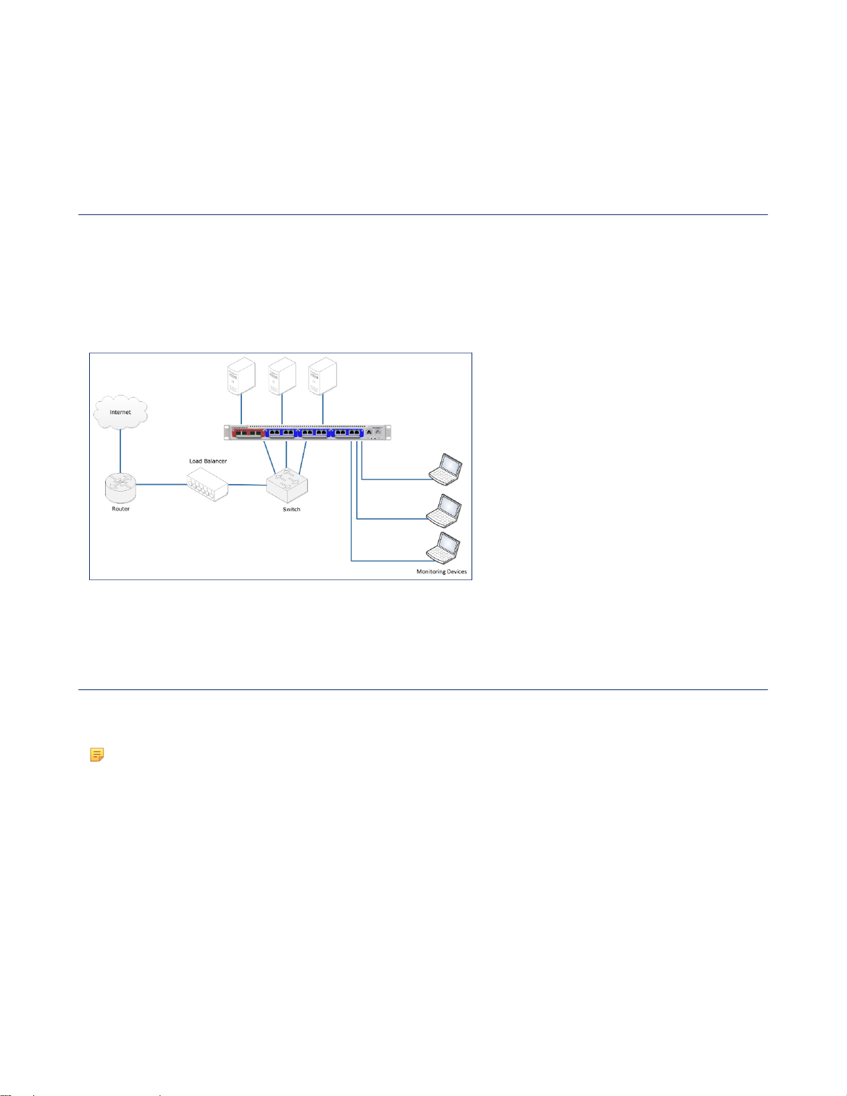
The following figure shows a configuration with three servers and three TAPs, one for each server. Each TAP is
connected to the AB ports of a SmartNA-X module (one module per server). If necessary, the resulting traffic streams can
be aggregated before sending to a network tool. A fully populated SmartNA-X device with four modules installed allows
up to four servers to be tapped (or more if C&D ports are used in TAP/failsafe mode).
Figure 3: TAPs placed on individual servers
TAP before a load balancer
You can place TAPs before a load balancer to monitor a group of servers with one TAP. In this location, you'll be able to
observe the IP addresses of individual requesters and have a better understanding of user traffic locations.
Note: Care must be taken when scheduling the TAP deployment, since all the servers on the segment will be
taken offline while the TAP is connected and configured.
A limitation of placing TAPs before a load balancer is that the balancer's IP address may take on the appearance of the
server providing the response to the requested information. If your preference is to follow which servers are responding to
the users request, you should place the TAP after the load balancer.
The following figure shows a configuration where a TAP is placed before a load balancer.
SmartNA-X™ 1G/10G User Guide 1.4 © 2015 Network Critical Solutions Limited
Page 15

SmartNA-X 1G/10G Modular | Introduction | 15
Figure 4: TAP configuration before a load balancer
TAP after a load balancer
You can place TAPs after a load balancer to monitor a group of servers with a single TAP. In this location, you'll be able
to observe which servers are responding to the requested information.
Note: Care must be taken when scheduling the TAP deployment, since all the servers on the segment will be
taken offline while the TAP is connected and configured.
A limitation of placing TAPs after a load balancer would be understanding who is requesting the information. The Load
Balancer typically will appear as the user address making the requester of data appear as a single user. Another possibility
to address recognizing a users location depends on the type of load balancer you are using. For example, if your load
balancer supports it you can enable “x-forward-for” so that the user IP is included in the packet information. Other
possibilities include instrumenting requester information into a custom field embedded in the application. Both methods
are common when monitoring user traffic.
The following figure shows a configuration where a TAP is placed after a load balancer.
SmartNA-X™ 1G/10G User Guide 1.4 © 2015 Network Critical Solutions Limited
Page 16

16 | Introduction | SmartNA-X 1G/10G Modular
Figure 5: TAP configuration before a load balancer
TAP between internet router and firewall
You can place a TAP between an internet router and a firewall to monitor the data exchanged between the public Internet
and your local Intranet.
Figure 6: TAP configuration between router and firewall
How to set up a TAP
You set up a TAP by connecting the SmartNA-X to your LAN and directing the received traffic to your network
monitoring tools for capture or analysis. Once the TAP has been installed its presence is transparent to traffic flowing
along that segment.
SmartNA-X™ 1G/10G User Guide 1.4 © 2015 Network Critical Solutions Limited
Page 17

SmartNA-X 1G/10G Modular | Introduction | 17
1.
Connect your live network to TAP ports A and B. If you are connecting to a 10G network, you must connect to the AB
ports of a 10G module fitted in slot 1 of the chassis. If connecting to a 1G network, you may use any of the AB ports,
including those in slot 1.
Verify that the LED link lights are on. If there is no link, you may need to reconfigure the port comm settings. See the
relevant step below.
2.
Map ports A and B to each other to join the live links and allow traffic to flow across the TAP.
Figure 7: Map A and B ports to join the live links
Assuming module 3, the equivalent CLI commands are:
CONTROLLER>set map 3a to 3b
CONTROLLER>set map 3b to 3a
3.
Map the live ports to output ports C and/or D as required.
Figure 8: Map A and B ports to C and/or D output ports
The equivalent CLI commands are as follows:
CONTROLLER>set map 3a to 3c
CONTROLLER>set map 3b to 3c
4.
Configure port usage and for copper ports, communication settings. In most cases, copper port settings can be left at
Auto, in which case the linked ports will negotiate the optimum settings themselves.
SmartNA-X™ 1G/10G User Guide 1.4 © 2015 Network Critical Solutions Limited
Page 18

18 | Introduction | SmartNA-X 1G/10G Modular
Figure 9: Configure port settings
The equivalent CLI commands for port 3A shown in the above figure are as follows:
CONTROLLER>select slot 3
SLOT3>set port A usage network
SLOT3>set port A autoneg
SLOT3>set port A mdi auto
SLOT3>set port A speed auto
SLOT3>set port A duplex auto
SLOT3>set port A mastering preferMaster
SLOT3>set port A tap LFP
5.
If required, define and apply filters to limit the packets sent to the output ports to a subset of the overall data stream.
Figure 10: Apply filters
The equivalent CLI commands for the filters shown in the above figure are as follows:
SLOT3>set map 3a to 3c require HTTP
SLOT3>set map 3b to 3d exclude HTTP
6.
Connect your network tool(s) to port C and/or D depending on whether you want to analyse data on the upstream or
downstream links, or both.
SmartNA-X™ 1G/10G User Guide 1.4 © 2015 Network Critical Solutions Limited
Page 19

Chapter 2
Getting Started
List of supplied components
The following components have been supplied with your SmartNA-X system.
• SmartNA-X 1U chassis.
• SmartNA-X TAP modules (models as per your order). Red modules are maximum 10 gigabit/second (10G bps), blue
modules are maximum 1 gigabit/second (1G bps).
• 10G optical cables.
• Serial management cable – DE-9 female to 8P8C (1.5 meters).
• SmartNA-X chassis rack ears (brackets and screws).
• 2 x power leads.
• Blanking plates to cover empty slots when running.
Please contact Network Critical Support ([email protected]) if any item is missing from the package.
Installing the chassis
To prevent unregulated access, the SmartNA-X chassis should be installed in a secure server rack with access to
authorized personnel only.
Caution: Static electricity can damage sensitive electronic components. To discharge static, fit an antistatic wriststrap or touch a bare metal surface before handling SmartNA-X components.
1.
Unpack all parts onto a clean workbench for inspection.
2.
Carefully check all parts against your order. If any parts are missing or have become damaged during shipping, please
report it immediately to Network Critical. See Contacting Network Critical on page 200 for contact information.
3.
Attach the rack ears to the sides of the chassis using the supplied screws.
Figure 11: Attach the rack ears to the SmartNA-X chassis
4.
Install the chassis in a 19" server rack. The chassis occupies one rack unit. Be sure to leave enough room for all the
cable connections (front and back), and for proper airflow and ventilation around the chassis.
SmartNA-X™ 1G/10G User Guide 1.4 © 2015 Network Critical Solutions Limited
Page 20
20 | Getting Started | SmartNA-X 1G/10G Modular
5.
Depending on whether your chassis is AC or DC powered, plug the chassis into an AC (100V-240V) or a DC (-42V to
-63V) supply. If your chassis has dual power sockets, make sure they are connected to independent supplies to ensure
the chassis is able to remain powered should either suffer a power cut.
6.
Turn on the chassis power switch(es) to start the system. Management interfaces will be available within two minutes,
but data ports will immediately begin to pass traffic.
7.
Connect management cables to the management ports, as described in Cabling for administrative connections on page
20.
Installing the TAP modules
TAP modules are hot-swappable and can be installed and removed while the chassis is powered up without affecting other
modules. Red 10G bps modules must only be installed in the left-most slot (Slot 1). Blue 1G bps modules may be installed
in any slot (Slots 1–4).
1.
Wear an anti-static wrist strap or take other precautions against electrostatic discharge (ESD) before handling the TAP
modules.
2.
Remove the TAP modules from their ESD bags. The modules are colour-coded as follows:
• Red – 10G bps maximum. Red modules must only be used in Slot 1 (left-most slot).
• Blue – 1G bps maximum. Blue modules may be used in any slot.
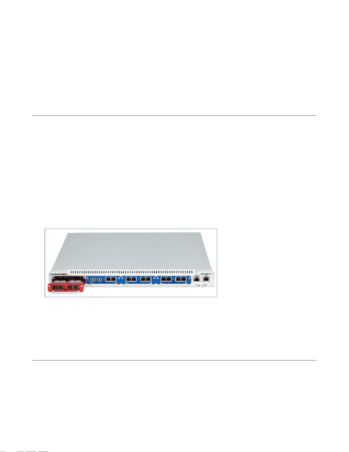
The following figure shows the correct placement of the 10G and 1G modules:
3.
Carefully slide the TAP modules into the chassis slots until they are fully inserted and flush with the chassis face. You
should feel a slight resistance as the module engages with contacts in the chassis. Note that red modules can only be
used in Slot 1, as shown in the figure below.
Figure 12: Install red 10G Modules in Slot 1 only
4.
Fit the supplied blanking plates to any remaining empty slots. This is to ensure correct cooling of the chassis during
operation.
Cabling for administrative connections
SmartNA-X provides dual administration ports for networked or serial access to the management interfaces. In most
cases, users will connect to the system remotely over a network. When first setting up, you may need to use the
CONSOLE in order to configure the network interface address.
SmartNA-X provides the following administration ports:
SmartNA-X™ 1G/10G User Guide 1.4 © 2015 Network Critical Solutions Limited
Page 21

SmartNA-X 1G/10G Modular | Getting Started | 21
MGMT port
This port allows remote network connections to the SmartNA-X web UI and CLI management interfaces. See,
Management port cabling for network access on page 22.
CONSOLE port
This port allows direct, serial connections to the command line interface (CLI).
Management port cabling for serial access
The CONSOLE port provides serial access to the CLI from a PC that is running terminal emulation software.
To complete this task, you will need:
• The supplied DE-9 female to 8P8C (RJ45) serial management cable cable (see figure below). This cable is also known
as a Cisco Console Cable, Cisco Management Cable, Yost Serial Cable, or Rollover Cable.
• A PC with a serial COM port.
• Terminal emulation software, such as PuTTY (http://www.chiark.greenend.org.uk/~sgtatham/putty/).
Figure 13: DE-9 female to 8P8C (RJ45) serial management cable
1.
Connect the RJ45 end of the DE-9 female to 8P8C (RJ45) serial management cable to the serial CONSOLE port.
2.
On your PC, open your preferred terminal emulation client and make sure the COM settings are as follows:
• Baud Rate: 9600 bps
• Data bits: 8
• Stop bits: 1
• Parity: None
3.
If the COM settings are correct, the SmartNA-X username prompt will be displayed on your terminal screen.
4.
To log on, enter your SmartNA-X administrator username and password. If login is successful, the CONTROLLER>
prompt is displayed, as shown below.
Username : admin
Password : ******
Login over serial connection
Command Line Parser
Built on Sep 25 2012 at 15:29:17 from svn revision 263M
Running at Authorization level 3
User admin logged in from serial-connection
CONTROLLER>
5.
Enter SmartNA-X CLI commands as required. Entering help outputs a list of available commands and other useful
information.
SmartNA-X™ 1G/10G User Guide 1.4 © 2015 Network Critical Solutions Limited
Page 22

22 | Getting Started | SmartNA-X 1G/10G Modular
6.
To logout and allow other users to access the management systems, enter exit. Note that there is an automatic default
timeout of 15 minutes for idle connections.
Management port cabling for network access
The MGMT port provides network access to the SmartNA-X web UI and CLI management interfaces.
1.
Connect an Ethernet cable to the MGMT port, and the other end to your network switch.
2.
Connect the Ethernet cable to a switch that allows access to networked management workstations. The default IP
address for SmartNA-X is 192.168.254.100.
Accessing the management interfaces
You can use a web browser or command line interface to configure SmartNA-X operations, including system settings,
user accounts, port configuration, and packet distribution from network ports to tool ports.
There are two ways to access the web and command line management interfaces:
• Locally, via a serial connection to the CONSOLE port.
• Remotely, via a HTTPS or SSH network connection to the MGMT port.
Connecting locally using the supplied serial cable
You can set up a local connection to SmartNA-X by attaching the supplied serial cable to the CONSOLE port and
connecting it to a PC running a terminal program. Local connections provide access to the CLI only.
1.
Connect the supplied DE-9 female to 8P8C (RJ45) serial management cable to the SmartNA-X CONSOLE port and
the PC's serial port.
2.
The SmartNA-X username prompt should be displayed on your terminal screen. If it is not, make sure the console
serial port is configured as follows:
• Baud Rate: 9600 bps
• Data bits: 8
• Stop bits: 1
• Parity: None
3.
Enter your SmartNA-X administrator username and password to login:
Username : admin
Password : ******
Login over serial connection
Command Line Parser
Built on Sep 25 2012 at 15:29:17 from svn revision 263M
Running at Authorization level 3
User admin logged in from serial-connection
CONTROLLER>
4.
At the prompt, enter SmartNA-X commands as required. To view/configure module settings, you must first select the
module slot with the select command. For example, to select the module in slot 1 enter:
CONTROLLER>select slot 1
SLOT1>
SmartNA-X™ 1G/10G User Guide 1.4 © 2015 Network Critical Solutions Limited
Page 23

SmartNA-X 1G/10G Modular | Getting Started | 23
5.
When you have finished, enter exit to logout and allow others users to access the system. You will be automatically
logged out after a default of 15 minutes if no commands are entered.
Connecting to the system
You can connect to the SmartNA-X management interfaces using a web browser or a terminal client. Both methods use
secure communication channels (HTTPS and SSH), and require users to be authenticated before access is granted. Only
one user may access the management interfaces at a time.
Connecting from a web browser
Connecting to the management port from a web browser provides user access to the SmartNA-X web user interface.
This allows the device to be managed using an intuitive, graphical user interface. In particular, the integrated Drag-nVu™ engine allows the easy creation of port maps by dragging from one port to another, and the application of filters by
clicking on a map and choosing a filter to apply.
1.
Before starting, ensure your PC has a web browser with the Oracle Java plugin installed. The security settings for Java
must be configured as follows:
•
Enable Java content in the browser: Enabled.
•
Security level for applications not on the Exception Site list: High.
•
Exception Site List: https://<device-address>.
Note: The IcedTea Java plugin installed on some Linux distributions is not compatible with the SmartNA-X
Java applet. Use the Oracle Java plugin instead.
2.
Open up a web browser and enter the IP address for SmartNA-X. If the address is correct, the SmartNA-X login page
will be displayed. See the following figure.
Figure 14: The SmartNA-X web UI login page
3.
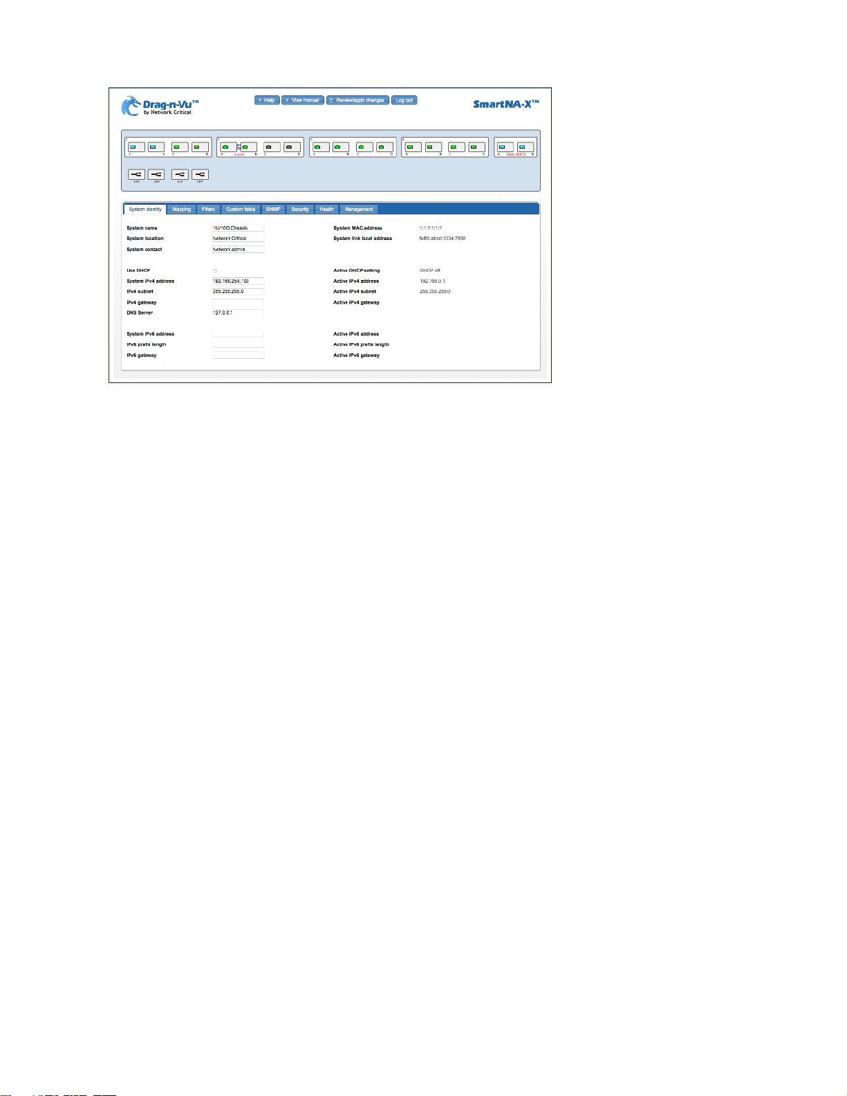
Enter the SmartNA-X user ID and password, and then click Log in to access the web UI, as shown in the following
figure.
SmartNA-X™ 1G/10G User Guide 1.4 © 2015 Network Critical Solutions Limited
Page 24
24 | Getting Started | SmartNA-X 1G/10G Modular
Figure 15: The SmartNA-X web UI
4.
Use the port diagram to configure system and port settings, create port maps, work with traffic filters, and view
diagnostic information as follows:
• Click anywhere within the chassis area to access the following system-wide options:
• System identity Settings for system name, contact, location, and network interface addresses (IPv4 and IPv6),
as well as information for the current IP address and MAC.
• Mapping
• Filters
• Custom fields
• VLAN Lists TPID and other options for VLAN tagging.
• SNMP Settings for configuring SNMP and enabling which notifications to send when an alert is generated.
• Security Settings for configuring RADIUS and TACACS+ Authentication and Accounting servers.
• Health Provides information about the health of the system (uptime, temperature, firmware revision, and so
on), and allows setting of the upper temperature threshold for the triggering of SNMP health notifications, and
the timeout period for rule generation for when applying maps and filters.
• Management Provides options for upgrading system firmware, installing Feature Packs, saving
configurations, uploading a custom SSL certificate, and for rebooting the system.
• Click on a module to access the following per-module settings:
• Health Provides similar information as the chassis health options (uptime, firmware revision, etc.), but for the
selected module instead.
• V-Line (Only available when a V-Line module is selected)
• Click on a port to access the following per-port options:
• Port configuration Settings for port description, usage, locking, force link up, and other communication
options for ports which allow this type of configuration.
• VLAN Settings for VLAN port tagging and QinQ packets.
• Traffic Provides traffic statistics, including number of bytes and packets in and out, and overall utilization as a
percentage of the port capacity.
• Errors Provides statistics on bad packets and other transmission errors received.
• SFP Provides information for SFP ports, including physical type, model, vendor information, and electrical
properties.
• Health Settings for traffic high and low thresholds that would trigger an SNMP health notification if exceeded.
SmartNA-X™ 1G/10G User Guide 1.4 © 2015 Network Critical Solutions Limited
Page 25

SmartNA-X 1G/10G Modular | Getting Started | 25
• Click on a port (ALT-click for multiple ports) and drag to another port to create a mapping between them.
• Click on a port map to set up packet filters.
5.
If you make changes to the configuration, click the Review/apply changes button to review and apply them.
6.
Click the Log out button when you have finished updating the system. This allows other users to access the system,
although there is a 15 minute idle timeout if you forget to logout.
Connecting from a terminal client
You can connect from a terminal client and use SmartNA-X commands to manage the system.
To connect from a terminal client, you'll need:
• Your SmartNA-X username and password.
• The network address for SmartNA-X.
• A terminal client that supports Secure Shell (SSH). On Linux and Mac OS, you can use the native Terminal client. On
Windows, you can use a third-party SSH client such as PuTTY (http://www.putty.org).
1.
In the terminal client, enter the following command:
$ ssh [email protected]
where 192.168.254.100 is the network address of SmartNA-X.
2.
If prompted, enter yes to add SmartNA-X to the list of known hosts:
The authenticity of host '192.168.254.100' can't be established.
RSA key fingerprint is 9a:30:7b:95:ec:b4:fe:53:e1:a4:42:69:4f:15:5c:1a.
Are you sure you want to continue connecting (yes/no)? yes
Warning: Permanently added '192.168.254.100' (RSA) to the list of known hosts.
3.
When prompted, type your SmartNA-X password and press enter. The SmartNA-X CONTROLLER> prompt is
displayed after logging in:
[email protected]’s password:*****
CONTROLLER>
4.
Enter commands to query or configure the system as required. You can get help on which commands are available by
entering the help command.
5.
When you have finished, enter exit or quit to close the connection and exit the CLI.
Configuring network settings
You may need to configure the network address to gain access to the management interfaces from networked management
stations. By default, the system is assigned the static IP address 192.168.254.0, as well as an IPv6 link-local address that
can be obtained from the System identity tab, as shown in the figure below.
If necessary, the network address can be configured in either of the following ways:
• Manual — You have to input the information, including system address and subnet mask. If your management station
is not in the same IP subnet as the unit, you will also need to specify the default gateway router.
• Dynamic — The unit can send IPv4 configuration requests to a DHCP address allocation server on the network.
SmartNA-X™ 1G/10G User Guide 1.4 © 2015 Network Critical Solutions Limited
Page 26
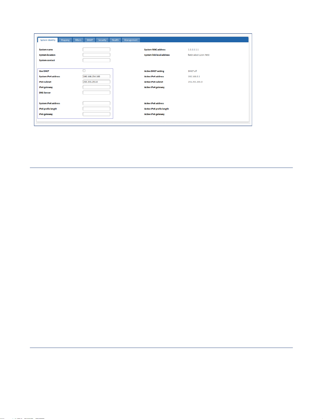
26 | Getting Started | SmartNA-X 1G/10G Modular
Figure 16: System identity tab network address options
Manual network configuration
You can manually assign an IPv4 or IPv6 addresses (or both) to the device. You may also need to specify a default
gateway that resides between this device and management stations that exist on another network segment.
1.
Click on the chassis and select the System identity tab.
2.
Turn off the Use DHCP checkbox.
3.
If assigning an IPv4 address, enter the IPv4 parameters.
• System IPv4 address—Enter the IPv4 network address in dotted-decimal format (a.b.c.d).
• IPv4 subnet—Enter the network address subnet mask in dotted-decimal format (a.b.c.d).
• IPv4 gateway—(Optional) Enter the IPv4 address of a default gateway that resides between this device and
management stations that exist on another network segment. The gateway address must be specified in dotteddecimal format (a.b.c.d).
• DNS Server—(Optional) Enter the IPv4 address of a default DNS server in dotted-decimal format (a.b.c.d).
4.
If assigning an IPv6 address, enter the IPv6 parameters.
• System IPv6 address—Enter the network interface IPv6 address, in standard IPv6 format, such as
2001:db8::52:0:1.
• IPv6 prefix length—Enter the network prefix length. The value must be in the range 16–124.
• IPv6 gateway—Enter the network gateway IPv6 address.
5.
Click Review/apply, review the changes you have made, and then click Apply to implement the new settings. After
a short delay you will be logged out as changes are implemented. You must now use the new IP address to connect to
the device.
Dynamic network configuration
The system supports dynamically allocated IPv4 network address values from a network DHCP address allocation server.
DHCP values can include the IP address, subnet mask, and default gateway. IPv6 address allocation is not supported by
the system.
1.
Click on the chassis and select the Security tab.
SmartNA-X™ 1G/10G User Guide 1.4 © 2015 Network Critical Solutions Limited
Page 27

SmartNA-X 1G/10G Modular | Getting Started | 27
2.
Select the Use DHCP checkbox.
3.
Click Review/apply, review the changes you have made, and then click Apply to implement the new settings. After
a short delay you will be logged out while changes are implemented. The system will begin broadcasting service
requests.
SmartNA-X™ 1G/10G User Guide 1.4 © 2015 Network Critical Solutions Limited
Page 28

28 | SmartNA-X Administration | SmartNA-X 1G/10G Modular
SmartNA-X Administration
Managing local users
Local users are directly authenticated by the device, rather than by an external RADIUS/TACACS+ Authentication
Server. When setting up a local user, you need to provide a username, a password, and an authorization level, either
Administrator, Operator, or Auditor. The authorization level is a security feature which limits the user to certain
management functionality, as follows:
• Administrators have full access to all system and port settings.
• Operators have access to port settings only.
• Auditors have read-only access to system and port settings.
Chapter 3
Local users are managed from the Local Users list, which is accessible from the Security tab after clicking Configure
local users.
Figure 17: Local Users list
Adding local users
1.
Click on the chassis and select the Security tab.
2.
Click Configure local users. The Local Users list displays.
3.
Click Add new user, or to modify an existing user, click . The Add/Edit user dialog displays, show below.
Figure 18: Add/Edit user dialog
4.
Enter the parameters:
SmartNA-X™ 1G/10G User Guide 1.4 © 2015 Network Critical Solutions Limited
Page 29
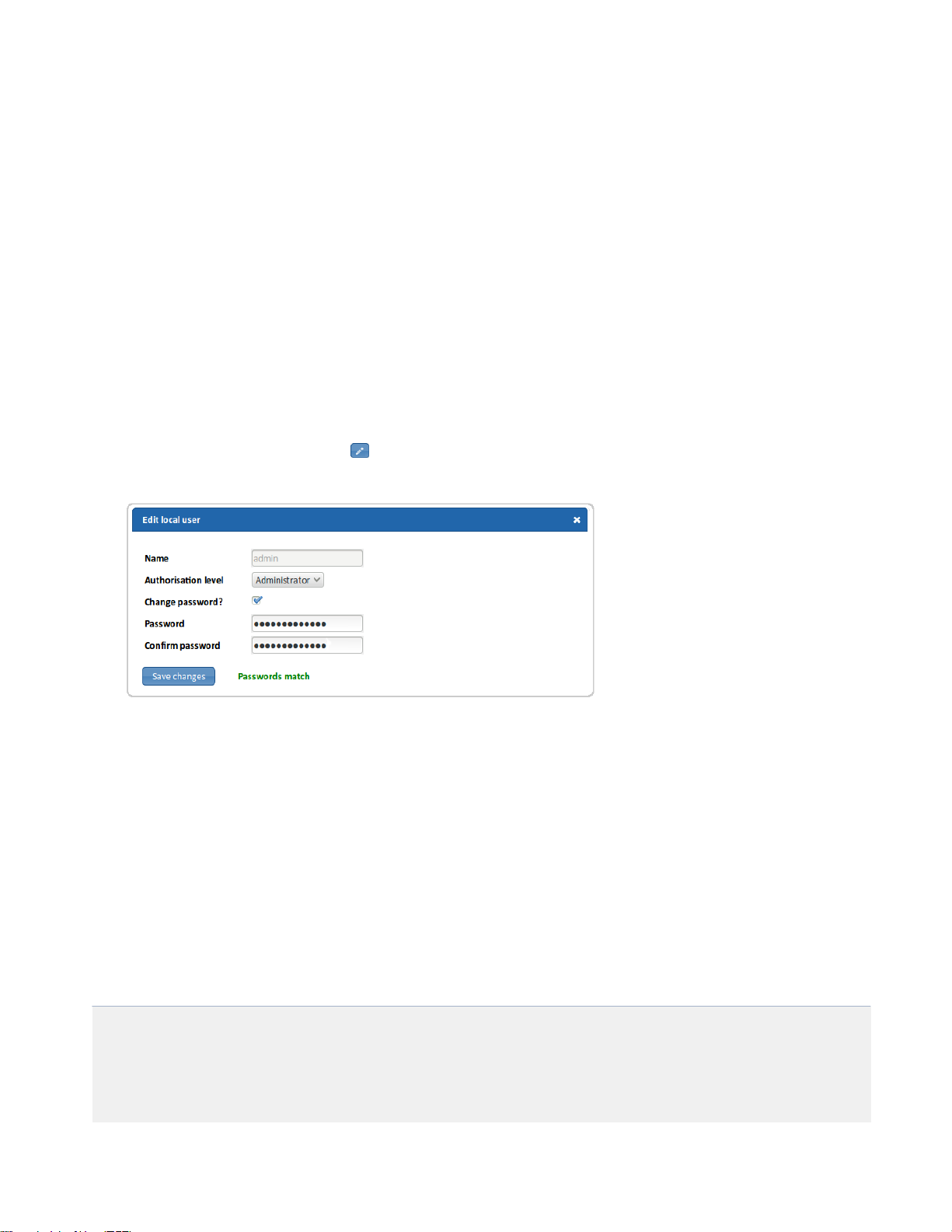
SmartNA-X 1G/10G Modular | SmartNA-X Administration | 29
• Name—Enter a new username. Spaces or UTF-8 characters are not permitted. Usernames are case-sensitive.
• Authorisation level—Select an access level.
• Password—Enter a password. Spaces or UTF-8 characters are not permitted. Passwords are case-sensitive.
• Confirm password—Enter the password again.
5.
Click Add user/Save changes. The user is added/modified.
6.
Click Review/apply and review pending changes. To apply these changes to the system, click Apply changes or click
'X' to cancel.
Managing user accounts
The system is supplied with default login passwords for Administrator, Operator, and Audit access. You can change them
in the web UI Security tab or with CLI commands.
1.
Log in to the web UI as Administrator.
2.
Click on the chassis and select the Security tab.
3.
Click Configure local users.
4.
In the Local Users list, click the edit icon for the Administrator account. The Edit local user dialog displays (see
figure).
Figure 19: The Edit local user dialog
5.
Select the Change password? checkbox.
6.
Enter a new password for the Administrator account. Passwords must not contain spaces and can be up to 1-80
alphanumeric characters in length.
7.
Click Save changes.
8.
Reset the passwords for the Operator and Audit accounts using the same procedure.
9.
Click Review/apply and review pending changes. To apply these changes to the system, click Apply changes or click
'X' to cancel.
Equivalent CLI commands for changing management passwords are follows:
CONTROLLER>show users
user : security level 2
admin : security level 3
audit : security level 1
CONTROLLER>set user Admin password new-password
Changing password for user Admin
SmartNA-X™ 1G/10G User Guide 1.4 © 2015 Network Critical Solutions Limited
Page 30

30 | SmartNA-X Administration | SmartNA-X 1G/10G Modular
CONTROLLER>set user User password new-password
Changing password for user User
CONTROLLER>set user Audit password new-password
Changing password for user Audit
Managing the system time
Network time synchronization is critical because every aspect of managing, securing, planning, and debugging a network
involves determining when events occur. Time also provides the only frame of reference between all devices on the
network.
Without synchronized time, accurately correlating log files between these devices is difficult, even impossible.
A few of the specific reasons include, tracking security breaches and network usage. Problems affecting a large number of
components can be nearly impossible to track if timestamps in logs are inaccurate. Time also reduces confusion in shared
file systems, as it is important for the modification times to be consistent, regardless of the machine on which the file
systems reside.
For these reasons, it is important that the time configured on the all devices on the network be accurate.
Note: The SmartNA-X device supports Network Time Protocol (NTP) and when enabled, the device dynamically
synchronizes the device time with the NTP server time. The device operates only as an NTP client, and cannot
provide time services to other devices.
Adding an NTP server
SmartNA-X can be configured to synchronize with your network NTP server.
1.
Click on the chassis and select the Security tab.
2.
In the NTP server field, enter the IP address of the network NTP server.
3.
Click Review/apply and review pending changes. To apply these changes to the system, click Apply changes or click
'X' to cancel.
Saving the current configuration
Administrators can save the current configuration to permanent memory to create a backup of port settings, port maps,
port maps, packet filters, and the SNMP configuration. User accounts and network settings are not saved, however.
1.
Click on the chassis and select the Management tab.
2.
Click Saved configurations. The Saved configurations dialog displays.
SmartNA-X™ 1G/10G User Guide 1.4 © 2015 Network Critical Solutions Limited
Page 31
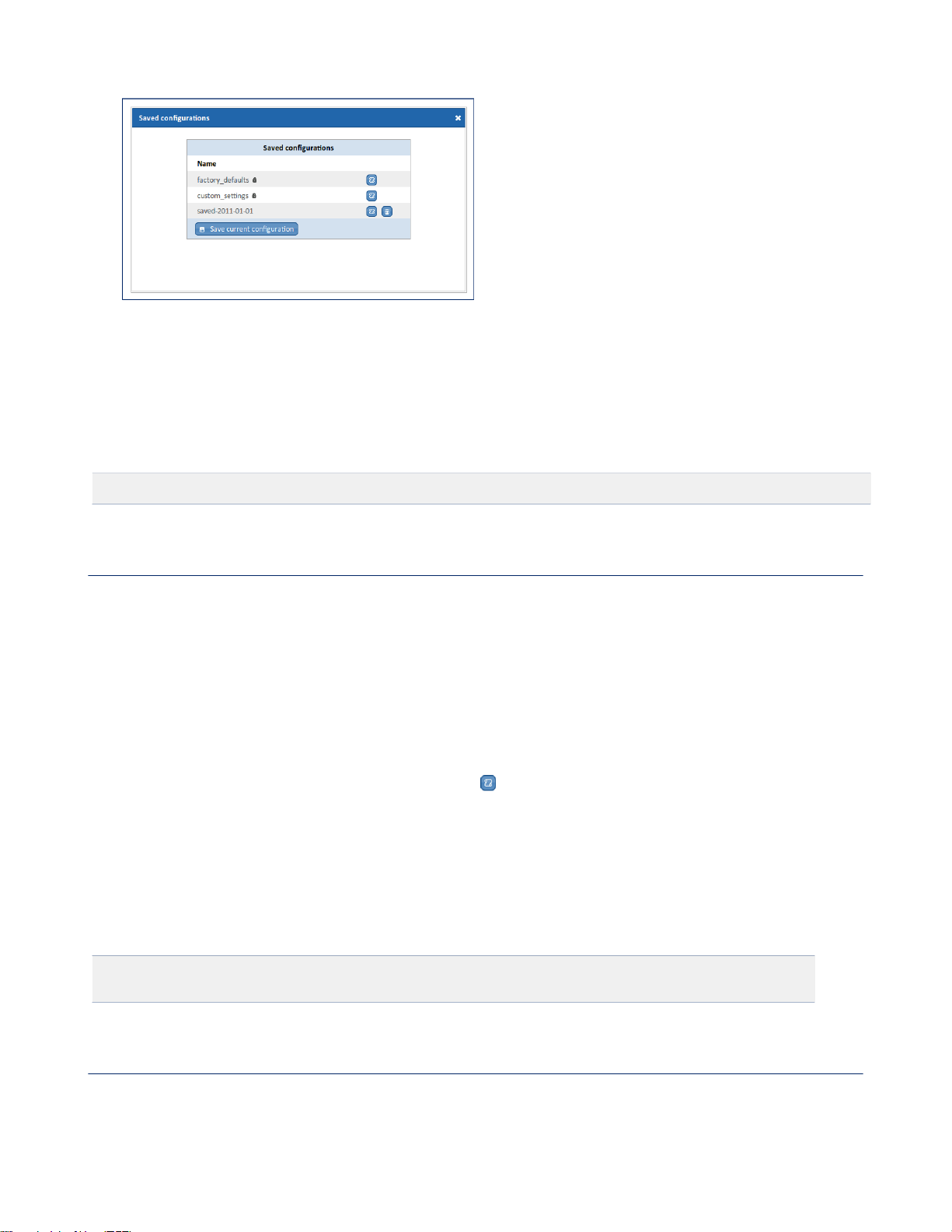
SmartNA-X 1G/10G Modular | SmartNA-X Administration | 31
Figure 20: Saved configurations dialog
3.
Click Save current configuration and enter a name for the configuration. Configuration names may contain up to 80
alphanumeric characters plus the underline character (’_’). Spaces are not permitted.
4.
Click Save to save the configuration.
The equivalent CLI command for saving the current configuration is as follows:
CONTROLLER>create settings filename
Loading a configuration
You can load a configuration from permanent memory to restore ports, maps, filters and SNMP settings to a
previous state. For example, you can restore the system to its factory default settings by loading the factory_defaults
configuration. You must be an Administrator to restore a configuration.
1.
Click on the chassis and select the Management tab.
2.
Click Saved configurations. The Saved configurations dialog displays with a list of available configurations.
Depending on your system installation, you may have several default configurations that have been pre-installed. For
example, all system have a factory_defaults configuration that can be used to reset the system back to its factory
configuration. Other default configurations may exist on your system.
3.
Select the configuration to restore and click the load icon .
4.
Click Load to load the configuration and overwrite the current configuration.
Using the CLI to restore a configuration
From the command line, you can restore a configuration from permanent memory using the create settings command and
the name of the configuration.
For example, to restore the configuration named My_SmartNA-X_configuration, enter the following command:
CONTROLLER>restore My_SmartNA-X_configuration
applied settings OK
Downloading the system configuration
You can download the system configuration to a text file for backup or transfer to another SmartNA-X device. The
configuration file is a complete backup of the system, and includes network interface settings and user accounts with
passwords removed.
SmartNA-X™ 1G/10G User Guide 1.4 © 2015 Network Critical Solutions Limited
Page 32

32 | SmartNA-X Administration | SmartNA-X 1G/10G Modular
Caution: The backup must not be used without first editing the network settings and user accounts. Failure to do
this may prevent access to the device for all users.
.
1.
Click on the chassis and select the Management tab.
2.
Click Download configuration. If necessary, accept the option to open a pop-up window in your browser.
3.
Copy all of the configuration information to text file and save it. Do not use spaces or other special characters in the
filename.
4.
Close the pop-up window when you have finished.
Uploading a system configuration
You can upload a system configuration to restore the system. When you do this, all current configurations for ports,
network and user accounts are overwritten by the new configuration.
Caution: To prevent becoming locked out of the system, only upload SmartNA-X configuration files that
have the correct network setting and user account names and passwords in place. Use a text editor to edit the
configuration file as necessary.
1.
Click on the chassis and select the Management tab.
2.
Click Upload configuration file, and click Continue. You will now be logged out of the system.
3.
Enter the Administrator username and password, click Choose file and navigate to the file you want to load.
Upgrade system firmware
Network Critical may occasionally release new versions of the system firmware to upgrade device functionality and
enhance performance.
Attention: Firmware updates should be scheduled for maintenance periods. Upgrading the system software may
cause fundamental changes to the device’s operation and affect links for several minutes.
To upgrade the system firmware
1.
Click on the chassis and select the Management tab.
2.
Click Update, and then click Continue.
You will be logged out and the Firmware update window will be displayed (see the figure below).
3.
Enter the Administrator username and password, and browse to the firmware file.
Caution: Applying incompatible firmware may render the device inoperable. Before applying a firmware
update always check the file is compatible with your device. Contact Network Critical Support for advice if
you are unsure.
4.
Click Upload new firmware.
The firmware upgrade takes a few minutes to complete, during which time you must not power off the device.
SmartNA-X™ 1G/10G User Guide 1.4 © 2015 Network Critical Solutions Limited
Page 33
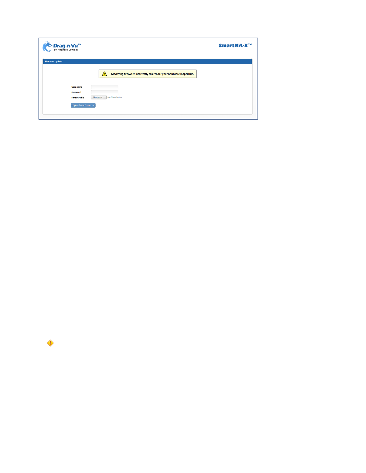
SmartNA-X 1G/10G Modular | SmartNA-X Administration | 33
Figure 21: The Firmware update window
Installing Feature Packs
Feature Packs are add-ons that can be installed to add additional features to SmartNA-X device be installed to add extra
port features for aggregation, filtering and load balancing.
Each pack feature pack activates up to any eight device ports across the full compliment of ports that are available. For
example, installing an Aggregation & Filtering & Load Balancing Feature Pack allows you set up a configuration with
two ingress ports and up to six egress ports. Configurations with more ports than the allowed limit are rejected by the
system and require the installation of additional Feature Packs before they can be applied successfully.
The following Feature Packs are available:
•
Aggregation Feature Pack
•
Aggregation & Filtering Feature Pack
•
Aggregation & Filtering & Load Balancing Feature Pack
Installing a Feature Pack
Administrators can install Feature Packs to add additional port capabilities to the system, including filtering and load
balancing. Each Feature Pack adds the advertised capabilities to 12 floating ports.
1.
Click on the chassis and select the Management tab.
2.
Click Install features, and then click Continue.
You will be logged out and the Feature pack installation window will be displayed (Figure 2234).
3.
Enter the Administrator username and password, and browse to the feature pack file supplied by Network Critical.
Caution: Installing an invalid feature pack may disable functionality in your device. Contact Network Critical
Support for advice if you are unsure.
4.
Click Install feature pack.
SmartNA-X™ 1G/10G User Guide 1.4 © 2015 Network Critical Solutions Limited
Page 34
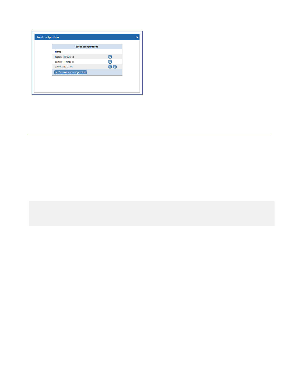
34 | SmartNA-X Administration | SmartNA-X 1G/10G Modular
Figure 22: Saved configurations dialog
Configuring system security
This section describes various aspects of security and access control. The system handles various types of security
including, user access control, user authentication, and transaction accounting.
Managing public host keys
SmartNA-X includes a default RSA public host key to verify that the host key presented during an SSH connection is in
fact SmartNA-X’s.
The first time you connect to SmartNA-X with an SSH client, the client will warn you that the host keys are not in your
local cache and show you the actual host key presented by SmartNA-X. Your client will most likely give you the option of
trusting the key, adding it to your local cache (see the following example output).
The authenticity of host '192.168.254.100' can't be established.
RSA key fingerprint is 9a:30:7b:95:ec:b4:fe:53:e1:a4:42:69:4f:15:5c:1a.
Are you sure you want to continue connecting (yes/no)? yes
Warning: Permanently added '192.168.254.100' (RSA) to the list of known hosts.
Once you’ve trusted the key, your client will alert you during connection if a different key is presented.
You may also upload your own public key certificates to replace the default public-key.
Changing public host keys
You can use the Upload SSL certificate option in the web UI to change the default public host keys provided with
SmartNA-X. Note, there is no facility for changing public hosts keys from the CLI.
1.
Click on the chassis and select the Management tab.
2.
Click Upload SSL certificate, and then click Continue. The Upload SSL certificate page displays.
SmartNA-X™ 1G/10G User Guide 1.4 © 2015 Network Critical Solutions Limited
Page 35

SmartNA-X 1G/10G Modular | SmartNA-X Administration | 35
Figure 23: Upload SSL certificate page
3.
Enter the Administrator username and password, and browse to the certificate file.
The certificate file must be in a .tar.bz2 file format, and must contain the following two files only:
• NetworkCritical.crt—X.509 certificate file (PEM-encoded; maximum 8192 bits)
• server.key—private key file (PEM-encoded; maximum 8192-bit)
Caution: Uploading an incorrect certificate could render the device inaccessible to network connections. If
this happens, you should connect via the serial Console port and perform a factory reset with instructions from
Network Critical Support.
4.
Click Upload new certificate and wait for the certificate file to be uploaded and verified. All new connections will be
verified using the new public-keys.
Configuring management access
You can assign authentication methods to management access methods, such as SSH, console, and HTTPS. This
authentication can be performed locally or on an external server, such as a TACACS+ or a RADIUS server.
User authentication occurs using the authentication methods that are selected, in no particular order. If the first
authentication method is not available, the next selected method is used. For example, if the selected authentication
methods are RADIUS and Local, and all configured RADIUS servers are queried in priority order and do not reply,
the user is authenticated locally. If an authentication method fails or the user has insufficient privilege level, the user is
denied access to the device. In other words, if authentication fails at an authentication method, the device stops; it does not
continue and does not attempt to use the next authentication method.
Defining authentication methods for access
1.
Click on the chassis and select the Security tab.
2.
Click on the icon next to Authenticate users. The Edit authentication types dialog displays (see the figure
below).
3.
Drag authentication methods into the desired order. Any authentication methods that are not required should be placed
below And ignore:, which can also be dragged into position.
The following authentication methods are available:
• Local—Username and password is checked against the data stored on the local device. These username and
password pairs are defined in the Local Users dialog.
• RADIUS—User is authenticated on a RADIUS server. You must have configured one or more RADIUS servers.
• TACACS+—User authenticated on the TACACS+ server. You must have configured one or more TACACS+
authentication servers.
4.
Click Review/apply and review pending changes. To apply these changes to the system, click Apply changes or click
'X' to cancel.
SmartNA-X™ 1G/10G User Guide 1.4 © 2015 Network Critical Solutions Limited
Page 36

36 | SmartNA-X Administration | SmartNA-X 1G/10G Modular
Figure 24: The Edit authentication types dialog
Configuring TACACS+ authentication servers
The SmartNA-X device can be configured as a Terminal Access Controller Access Control System (TACACS+) client
that relies on a TACACS+ server to provide centralized security, authorizing and authenticating users attempting to access
and administer the unit.
TACACS+ provides the following services:
• Authentication—Provides authentication of administrators logging onto the unit by using usernames and user-defined
passwords.
• Authorization—Performed at login. After the authentication session is completed, an authorization session starts using
the authenticated username. The TACACS+ server then checks user privileges.
• Accounting—Enable accounting of login sessions using the TACACS+ server. This enables a system administrator to
generate accounting reports from the TACACS+ server.
After the authentication session is completed, an authorization session starts using the authenticated username. The
TACACS+ server then checks user privileges. The TACACS+ protocol ensures network integrity, through encrypted
protocol exchanges between the device and the TACACS+ server.
TACACS+ is supported only with IPv4.
TACACS+ servers cannot be used as 802.1X authentication servers to verify credentials of network users trying to join
the networks through the unit.
Some TACACS+ servers support a single connection that enables the device to receive all information in a single
connection. If the TACACS+ server does not support this, the device reverts back to multiple connections.
TACACS+ authentication servers can be configured using the TACACS+ authentication dialog, shown below.
Figure 25: TACACS+ authentication servers dialog
SmartNA-X™ 1G/10G User Guide 1.4 © 2015 Network Critical Solutions Limited
Page 37

SmartNA-X 1G/10G Modular | SmartNA-X Administration | 37
TACACS+ workflow
This device uses CHAP (Challenge-Handshake Authentication Protocol) when authenticating users with the TACACS+
server. To use a TACACS+ server, do the following:
1.
Open an account for a user on the TACACS+ server.
2.
On that server, configure the user or group privileges to 1 for an Audit user, 2 for an Operator, or 3 for an
Administrator. For example, privilege level 2 is given to a user or group of users on the TACACS+ server by the
following string in the user or group definition:
service = exec
{ priv-lvl = 2
}
3.
Specify TACACS+ as the authentication method, so that when a user logs onto the device, authentication is performed
on the TACACS+ server instead of locally.
Note: If more than one TACACS+ server has been configured, the device uses the configured priorities of
the available TACACS+ servers to select the TACACS+ server to be used by the device. As shown in the
following figure, server priority can be changed by dragging the servers into the required order. Servers at the
top of the list have the highest priority.
Figure 26: Drag servers up and down the servers list to configure server priority
Configure TACACS+ authentication servers
1.
Click on the chassis and select the Security tab.
Existing TACACS+ authentication servers are shown in the TACACS+ authentication dialog.
2.
To add a new TACACS+ community, click Add server, or, to edit an existing community, click the icon for that
server. The Add TACACS+ server dialog displays, shown below.
3.
Enter the IPv4 address of the TACACS+ authentication server and click Add/Save. The server is added to the list of
TACACS+ authentication servers.
4.
If several servers have been configured and you wish to prioritize the order in which they are contacted, use the
Arrange icon to drag servers into position. Servers at the top of the list have highest priority and are contacted
first.
5.
Click Set shared secret and enter the shared secret for your TACACS+ authentication server(s).
6.
Click Review/apply and review pending changes. To apply these changes to the system, click Apply changes or click
'X' to cancel.
SmartNA-X™ 1G/10G User Guide 1.4 © 2015 Network Critical Solutions Limited
Page 38
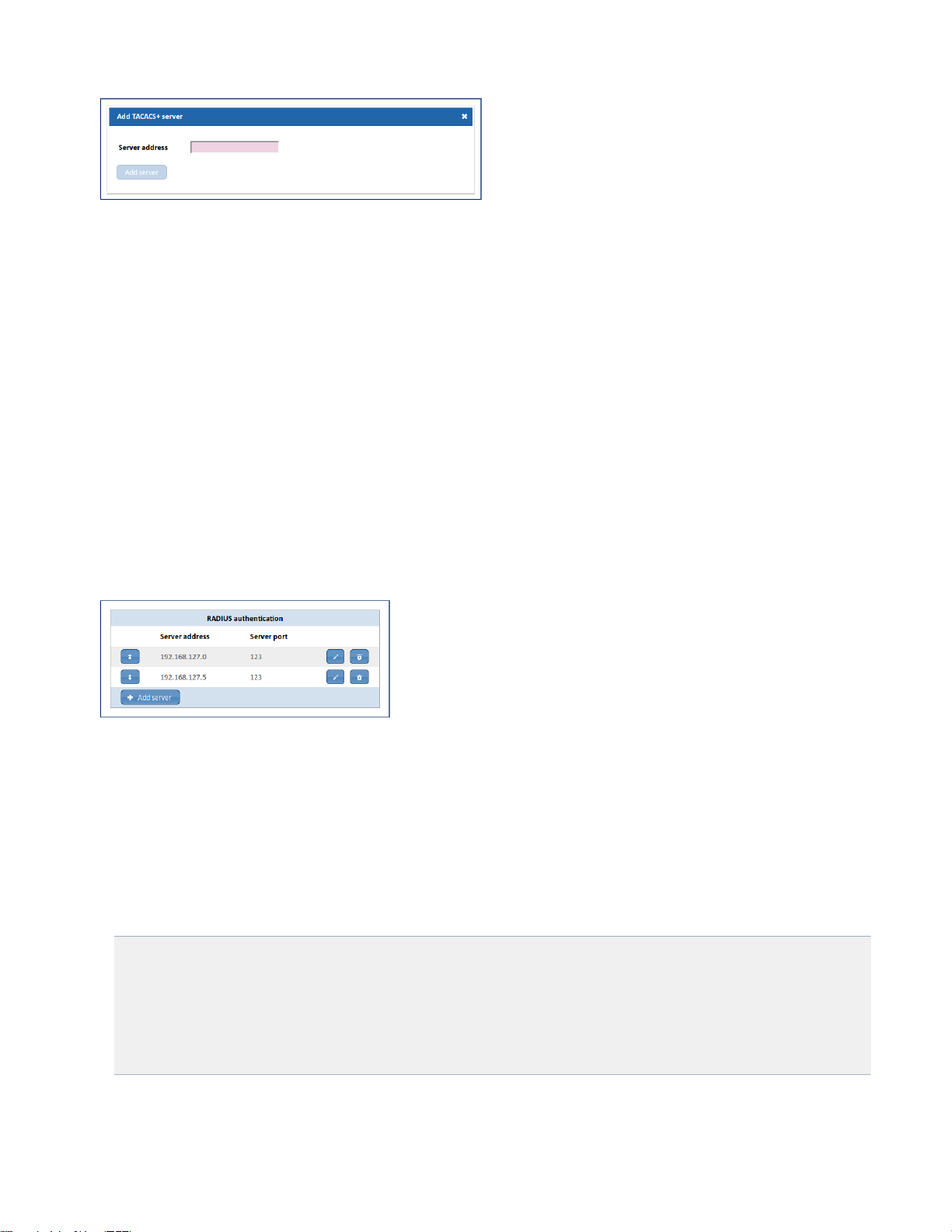
38 | SmartNA-X Administration | SmartNA-X 1G/10G Modular
Figure 27: Add TACACS+ server window
Configuring RADIUS authentication servers
Remote Authorization Dial-In User Service (RADIUS) servers provide a centralized 802.1X or MAC-based network
access control. The device is a RADIUS client that can use a RADIUS server to provide centralized security.
An organization can establish a Remote Authorization Dial-In User Service (RADIUS) server to provide centralized
802.1X or MAC-based network access control for all of its devices. In this way, authentication and authorization can be
handled on a single server for all devices in the organization.
The device can act as a RADIUS client that uses the RADIUS server for the following services:
• Authentication—Provides authentication of regular and 802.1X users logging onto the device by using usernames and
user-defined passwords.
• Authorization—Performed at login. After the authentication session is completed, an authorization session starts using
the authenticated username. The RADIUS server then checks user privileges.
• Accounting—Enable accounting of login sessions using the RADIUS server. This enables a system administrator to
generate accounting reports from the RADIUS server.
RADIUS authentication servers can be configured using the RADIUS authentication dialog, shown below.
Figure 28: RADIUS authentication server list
RADIUS workflow
This device uses PAP (Password Authentication Protocol) when authenticating users with the RADIUS server. To use a
RADIUS server, do the following:
1.
Open an account for the device on the RADIUS server.
2.
In that server’s radiusd.conf configuration file, add users and configure the Reply-Message attribute so that it
contains “audit”, “user”, or “admin” for the respective Audit, Operator, and Administrator account. For example:
user1 Cleartext-Password := “User1Password
Reply-Message = "audit"
user2 Cleartext-Password := “User2Password
Reply-Message = "user"
user3 Cleartext-Password := “User3Password
Reply-Message = "admin"
3.
Specify RADIUS as the authentication method, so that when a user logs onto the device, authentication is performed
on the RADIUS server instead of locally.
SmartNA-X™ 1G/10G User Guide 1.4 © 2015 Network Critical Solutions Limited
Page 39
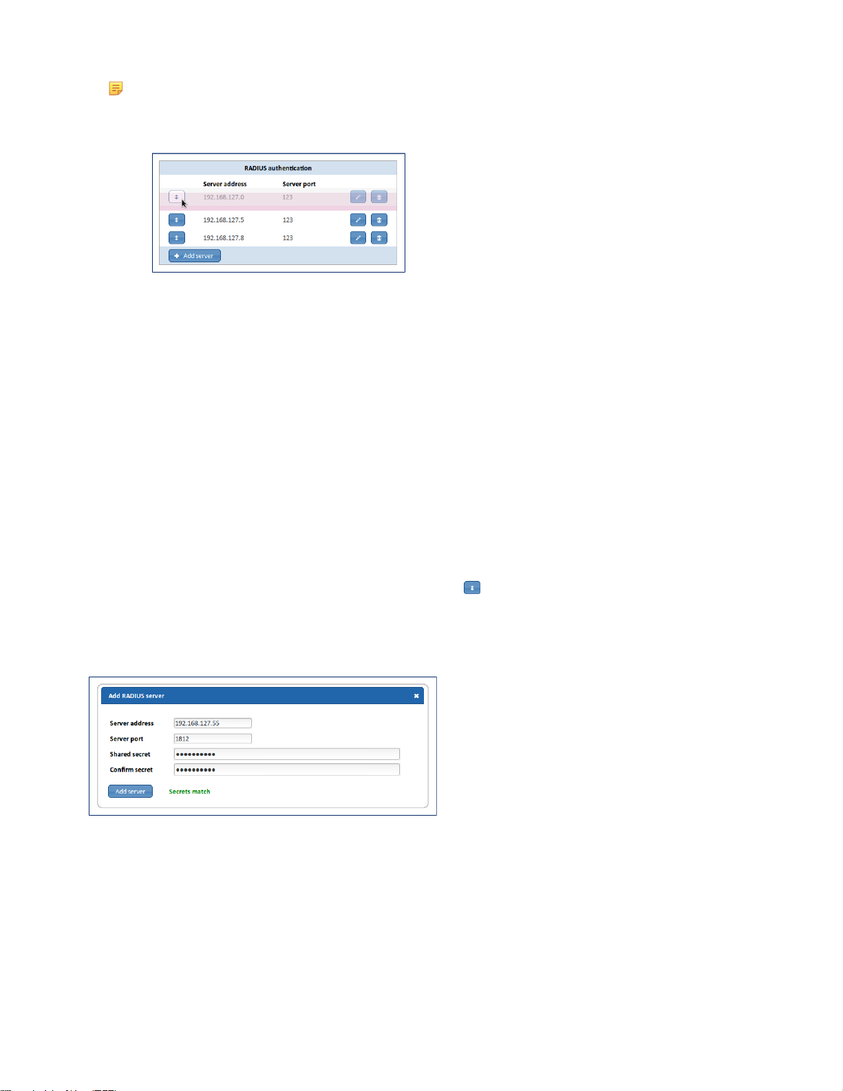
SmartNA-X 1G/10G Modular | SmartNA-X Administration | 39
Note: If more than one RADIUS server has been configured, the device uses the configured priorities of the
available RADIUS servers to select the RADIUS server to be used by the device. As shown in the following
figure, server priority can be changed by dragging the servers into the required order. Servers at the top of the
list have the highest priority.
Figure 29: Drag servers up and down the servers list to configure server priority
Configure RADIUS authentication servers
1.
Click on the chassis and select the Security tab.
Existing RADIUS authentication servers are displayed in the RADIUS authentication server dialog.
2.
Click Add server.
3.
In the Add RADIUS server dialog (shown below), enter the parameters:
• Server address—Enter the server’s IPv4 address.
• Server port—Enter the UDP port number, usually port 1812 for RADUS authentication servers.
• Shared secret—Enter the RADIUS server’s shared secret.
• Confirm secret—Enter the shared secret again to confirm it.
4.
Click Add server. The server is added to the list of RADIUS accounting servers.
5.
If desired, arrange server priority by dragging with the Arrange control. Servers at the top of the list are contacted
first.
6.
Click Review/apply and review pending changes. To apply these changes to the system, click Apply changes or click
'X' to cancel.
Figure 30: Adding a RADIUS authentication server
Managing transaction logging
Accounting gives the ability to track usage, such as user access, the ability to log the data gathered to a database, and the
ability to produce reports on the data gathered.
Although the SmartNA-X does not locally support accounting, you can enable an AAA accounting server running
RADIUS or TACACS+ and have accounting information logged by the AAA server.
SmartNA-X™ 1G/10G User Guide 1.4 © 2015 Network Critical Solutions Limited
Page 40
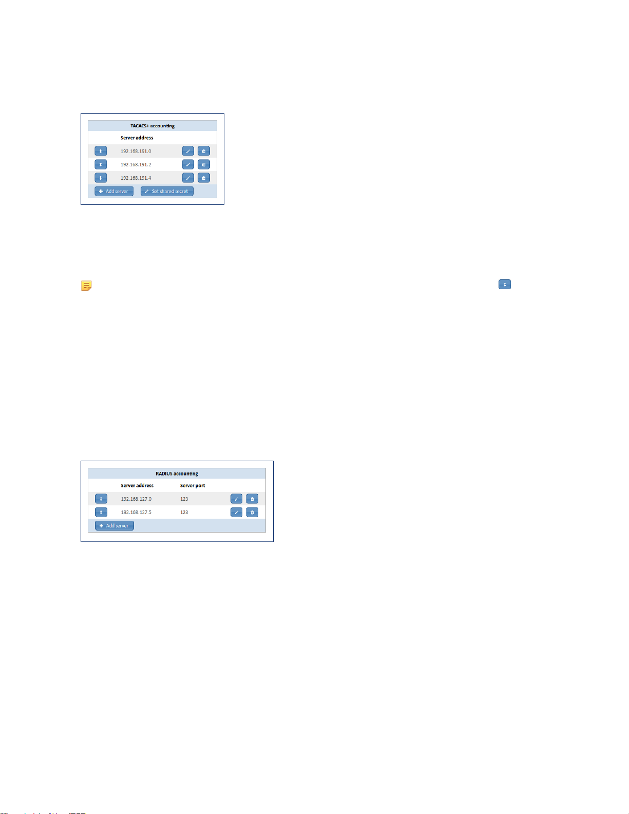
40 | SmartNA-X Administration | SmartNA-X 1G/10G Modular
Add TACACS+ accounting servers
1.
Click on the chassis and select the Security tab.
Any existing TACACS+ accounting servers are shown in the TACACS+ accounting dialog, shown below.
Figure 31: TACACS+ accounting servers list
2.
Click Add server and enter the IPv4 address of the TACACS+ accounting server. The server is added to the list of
TACACS+ accounting servers.
Note: If you have multiple servers set up, you can organize server priority with the Arrange by dragging
the servers into the required order. Servers higher up the list have higher priority than those further down and
will be contacted first.
3.
If you have not done so already, click Set shared secret and enter the global shared secret for the TACACS+
accounting servers.
4.
Click Review/apply and review pending changes. To apply these changes to the system, click Apply changes or click
'X' to cancel.
Add RADIUS accounting servers
1.
Click on the chassis and select the Security tab.
Any RADIUS accounting servers already been set up will be shown in the RADIUS accounting server list, shown
below.
Figure 32: RADIUS accounting server list
2.
Click Add server and enter the RADIUS accounting server’s parameters in the Add RADIUS server (shown below):
• Server address—Enter the RADIUS server’s IPv4 address.
• Server port—Enter the UDP port number, usually port 1813 for RADUS accounting servers.
• Shared secret—Enter the RADIUS accounting server’s shared secret.
• Confirm secret—Enter the shared secret again to confirm it.
SmartNA-X™ 1G/10G User Guide 1.4 © 2015 Network Critical Solutions Limited
Page 41
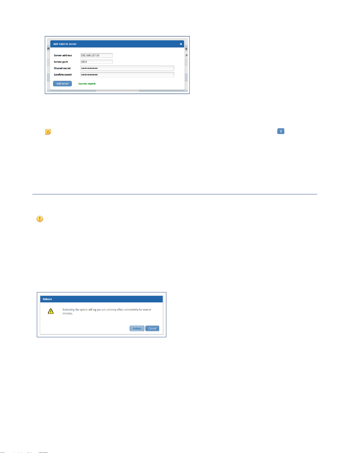
SmartNA-X 1G/10G Modular | SmartNA-X Administration | 41
Figure 33: Add RADIUS server dialog
3.
Click Add server. The server is added to the list of RADIUS accounting servers.
Note: If you have multiple servers set up, you can organize server priority with the Arrange control by
dragging the servers into the required order. Servers higher up the list have higher priority than those further
down and will be contacted first.
4.
Click Review/apply and review pending changes. To apply these changes to the system, click Apply changes or click
'X' to cancel.
Rebooting the system
You can reboot the device to reset all components of the system to the last saved/applied configuration. Any pending
updates will be lost unless applied prior to rebooting.
Attention: A reboot takes around 2–3 minutes. During this time you will be unable to login to the system and all
network traffic on the live ports will be stopped, including copper ports with TAP mode/failsafe enabled.
Reboot the system
1.
Click on the chassis and select the Management tab.
2.
From the management options, click Reboot. The Reboot dialog displays (see figure below).
3.
Click Reboot. The device will now reboot. All traffic entering/leaving the device will be stopped for 2–3 minutes
while the device reboots.
Figure 34: Reboot dialog
SmartNA-X™ 1G/10G User Guide 1.4 © 2015 Network Critical Solutions Limited
Page 42

42 | Configuring Ports | SmartNA-X 1G/10G Modular
Configuring Ports
Configuring Ports
The SmartNA-X chassis can house up to four independently operating modules. Each module contains four ports (A–D),
which operate in pairs (AB and CD). At the rear of the chassis are two 10G ports (R0 and R1). All ports support full-rate
data throughput at the advertised rate, and can be mapped to any other port regardless of any differing physical properties.
Working with copper ports
When working with copper ports, you may need to configure port settings in order to establish an efficient connection
with the link partner.
Chapter 4
In most cases, you can leave the port set to auto-negotiation, whereby the ports themselves determine the optimum
connection properties. To safeguard a TAP against device failures, you can enable port failsafe by turning on TAP mode.
About auto-negotiation
Auto-negotiation automatically determines optimum settings for port speed, duplex and mastery, but not MDI. Under
normal operations you can leave auto-negotiation enabled.
Copper ports can operate with auto-negotiation ON or OFF. This setting is controlled by the Auto-Negotiation option in
the web UI, or by the set port autoneg command in the CLI. Under normal operations, you should leave auto-negotiation
ON. If you set auto-negotiation to OFF the port will be limited to 100M bps.
Auto-negotiation set to OFF
The following details should be noted when auto-negotiation is set to OFF:
• Port duplex setting must be either full-duplex or half-duplex (not "auto"), and must match the link partner setting.
• Port speed setting must be either 10M or 100M (not 1G or "auto"), and must match the link partner setting.
• Port mastery setting is irrelevant.
If auto-negotiation is OFF the speed and duplex settings must match those of the link partner. If the partner port is set to
auto-negotiation, the partner port will attempt to connect in half-duplex mode, leading to a mismatch if the SmartNAX port is set to full-duplex. Therefore, it is best to set auto-negotiation OFF on the partner port when auto-negotiation is
turned off.
Auto-negotiation set to ON
Normally, you should set port speed to "auto" and duplex to "auto". However, it is possible to restrict the capability
advertisement during auto-negotiation to a single speed setting and/or a single duplex setting by setting speed to 10M,
100M or 1G, and/or duplex to half- or full-. For example, if duplex is set to full and speed to 100M the port will only
connect at 100M full duplex.
About MDI
Port MDI setting controls the MDI/MDI-X cable crossover mode for a copper port.
Selecting auto enables the port to automatically set MDI crossover correctly. If you prefer to use a fixed MDI setting (that
is, not auto), you must ensure the link partner is set to the opposite MDI/MDI-X setting or is using auto.
If using the same settings on both ends, you must use an Ethernet crossover cable to ensure the transmit and receive
signals are matched at the connector level.
SmartNA-X™ 1G/10G User Guide 1.4 © 2015 Network Critical Solutions Limited
Page 43

SmartNA-X 1G/10G Modular | Configuring Ports | 43
About TAP mode
TAP mode allows copper ports to maintain connection through a port pairing (AB or CD) in the event of a power failure.
This feature is known as "failsafe" and is available for RJ ports only, not SFP ports.
Failsafe works by continually monitoring power to the TAP ports. If power is lost, failsafe activates a relay switch
across the port pairing (AB and/or CD) to allow traffic to keep flowing. When power to the device is restored, failsafe
deactivates the relay and returns the device to managed operations once more.
There will only be a very brief interruption of traffic while the connection switches to the relay, and again when it changes
back to normal as power is restored. The port settings must be configured so the two partner ports are compatible when
connected directly to each other via the failsafe relays.
The SmartNA-X TAP modules have a feature called "fast-failsafe" that minimises the interruption to traffic when power is
restored, by reducing the probability of an auto-negotiation process. To take advantage of this feature, use LFP (not LMP),
and it is advisable to set both sides to advertise only 1G full-duplex, and to set both sides' MDI settings to non- auto (that
is, MDI or MDI-X). The partner ports must use opposite MDI settings (assuming no crossover cables are used).
LFP (Link Failure Propagation)
LFP is a TAP mode that allows link failures in a port pairing to be propagated to the partner port such that if either side
goes down the other side is also taken down.
LMP (Link Mode Propagation)
LMP is a TAP mode that can be applied to a port pair to make the presence of the TAP relatively invisible to the partner
ports.
LMP extends LFP by making each of the TAP links behave as if it were the nominal partner. Thus, if you connect
device X to port A and device Y to port B, A behaves as if it were Y and B as if it were X, making the presence of a TAP
relatively invisible to the partner ports.
LMP is a TAP mode option that can be chosen instead of LFP, giving three possibilities: None, LFP, or LMP. When LMP
is selected it has control over the speed, duplex and master/slave characteristics of the ports, and the effect of changes to
speed, duplex, and master/slave mode is postponed until LMP is switched off. Until the link is up at both ends each port
will be disabled, which prevents any traffic travelling over half of the link while the other half is down.
Note that switching LMP on will cause the ports to go down initially before establishing a link. LFP links take longer to
establish than LFP.
LMP and half-duplex mismatches
When using LMP, duplex mismatches occur when either of the link partner ports is set to non-auto half-duplex, as
follows:
• A=Half duplex, B=Auto-negotiation: There will be a duplex mismatch at B that would not occur with a direct
connection.
• A=Half duplex, B=Full duplex: There will be a connection at B without the duplex mismatch that would usually occur
(although but this may be irrelevant as there is a mismatch at A).
• A=Half duplex, B=Half duplex: There will be a duplex mismatch that would not occur with a direct connection.
Avoiding duplex mismatches
A duplex mismatch occurs when two connected devices operate in different duplex modes. That is, one device operates in
half-duplex mode whilst the other device operates in full-duplex mode.
A duplex mismatch is often the cause of slow and unreliable connections and may produce fragmented packets.
Duplex mismatches can occur when:
• One of the ports is set to full-duplex and the other is set to half-duplex.
• One of the ports is set to auto-negotiate and the other is set to full-duplex.
In the second scenario, the port set to auto-negotiate will connect in half-duplex mode, resulting in a duplex mismatch.
This type of behaviour is described in IEEE802.3-2008 Section 3: 37.1.4.4 and is a requirement for legacy devices that
support half-duplex mode only.
SmartNA-X™ 1G/10G User Guide 1.4 © 2015 Network Critical Solutions Limited
Page 44

44 | Configuring Ports | SmartNA-X 1G/10G Modular
The recommended advice on avoiding duplex mismatches is to:
•
Enable auto-negotiation on both ports, or
• Turn off auto-negotiation and use the same fixed duplex setting on both ports.
Configuring port settings
Configure port settings to specify description and usage information, to secure ports by locking them or enabling autolock, and to specify communication options and a TAP failsafe mode when working with copper ports.
1.
Click on the port(s) you want to configure.
2.
In the Port Configuration tab, specify the appropriate port options as follows:
• Description—Enter the port user-defined name or comment.
•
Usage—Select whether the port is connected to a live network (Network), is connected to a network tool (Tool), or
is currently not connected (Unknown)
• Speed—(Dual rate optical SFP ports only)—Select the configured rate for the port, either 10G or 1G.
• The following settings apply to copper ports only:
•
Auto-Negotiation—Select Auto-neg to allow port auto-negotiation, or Off (fixed) to prevent it. If enabled, auto-
negotiation is always used for speed and duplex, even when a specific speed or duplex mode is specified.
•
Speed—Select the configured rate for the port, or select Auto to allow the port to auto-negotiate the optimum
speed with the link partner.
Note: V-Line ports must be set to 1G bps when mapped to other TAP modules. Setting any other port
speed will prevent data transfer between the mapped ports.
•
MDI—Select the crossover mode of the port, either MDI (normal), MDI-X (crossover), or Auto. An Ethernet
crossover cable must be used if port link partners are using the same MDI setting (MDI to MDI or MDI-X to
MDI-X).
•
Duplex—Select the duplex mode, either Full for full-duplex, Half for half-duplex, or Auto to allow either.
• Mastery—Select the port mastery for clock synchronization. A link will only function correctly if there is
one master and one slave. Note that Mastery has no effect when Auto-Negotiation is turned off. The available
Mastery options are:
• Force master—Force synchronization master (link partner must be set to slave).
• Force slave—Force synchronization slave (link partner must be set to master).
• Prefer master—Favour synchronization master.
• Prefer slave—Favour synchronization slave.
• TAP—(only available on copper and fixed fibre ports with optical relays). Choose from the following options
(note that some of these options may not be available depending on the port or module type):
•
Off—Disables failsafe, LFP and LMP.
•
LFP—Enables port failsafe and LFP mode (Link Failure Propagation) mode.
•
LMP—Enables port failsafe and LMP (Link Mode Propagation) mode.
For more information about failsafe, LFP, and LMP see About TAP mode on page 43.
• Autolock—Select the check box to enable automatic locking of the port when a link-down status is detected. If
triggered, for instance by the removal of a cable at either end of the link, the port immediately locks so no traffic
passes in or out. To unlock the port after an autolock, re-attach the cable and then clear the Lock checkbox.
• Lock—Select the check box to lock the port. A locked port will not pass traffic in or out.
3.
Click Review/apply and review pending changes. To apply these changes to the system, click Apply changes or click
'X' to cancel.
SmartNA-X™ 1G/10G User Guide 1.4 © 2015 Network Critical Solutions Limited
Page 45
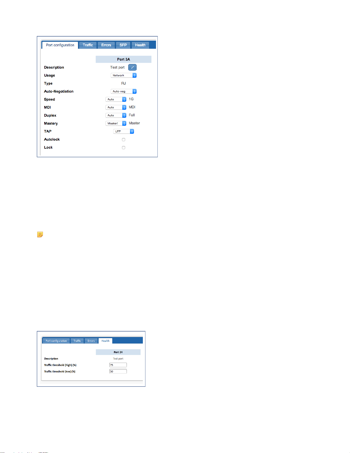
Figure 35: Port configuration dialog (RJ/copper port)
SmartNA-X 1G/10G Modular | Configuring Ports | 45
Configuring port traffic thresholds
Traffic thresholds can be set on each port to warn when traffic levels are reaching the port's maximum carrying capacity
(this option is not available for ports in V-Line modules). Should the traffic level exceed the high threshold level, an
SNMP system notification will be sent to all configured SNMP hosts. The warning will be cleared when the level falls
below the low threshold level (do not set the low threshold value too close to the high value or 'fluttering' may occur,
whereby notifications are continually being sent).
Note: Port traffic thresholds do not cause port throttling (discarding of packets) to occur when the high threshold
level is exceeded. Packets will only be discarded if the maximum carrying capacity of the port is surpassed.
1.
Click on the port to access port information and configuration options. Multiple ports can be selected by holding down
<Shift> and clicking on additional ports.
2.
Click on the Health tab. The port health options are displayed.
3.
Enter percentage values (of the overall port capacity) for Traffic threshold (high) % and Traffic threshold (low) %.
A notification is generated when the level is exceeded, thus setting values of 0 (low threshold) or 100 (high threshold)
prevents notifications being generated. See Defining notification (trap) settings on page 78 for information on
configuring notifications and hosts.
4.
Click Review/apply and review pending changes. To apply these changes to the system, click Apply changes or click
'X' to cancel.
Figure 36: Port Health options
SmartNA-X™ 1G/10G User Guide 1.4 © 2015 Network Critical Solutions Limited
Page 46
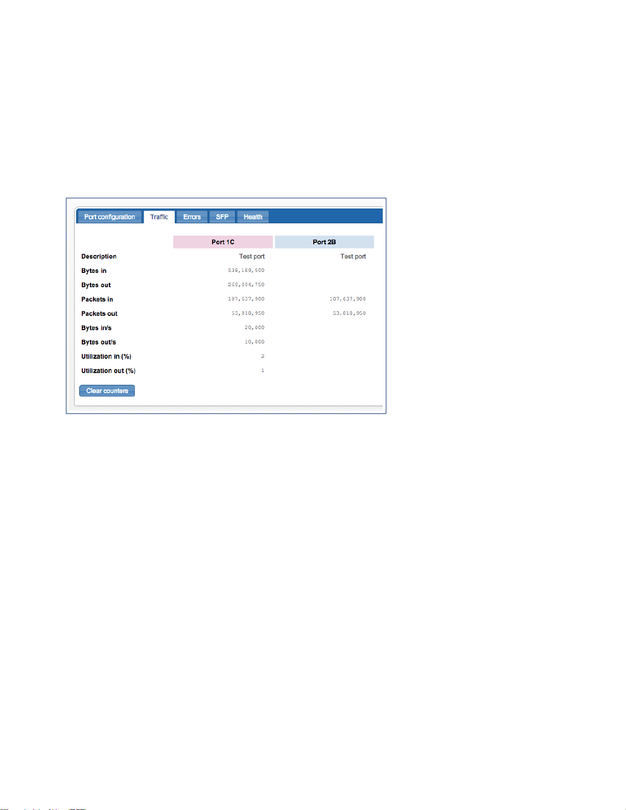
46 | Configuring Ports | SmartNA-X 1G/10G Modular
Viewing port statistics
For each port (except V-Line ports) the system provides details for the total number of bytes sent and received, port
utilization percentages, undersized and fragmented packet errors, and other statistical information. For SFP ports, the
system also provides transceiver and physical link information.
For V-Line ports the system provides a limited set of statistics that comprises packet (not octets) counts only and no error
statistics.
Viewing traffic statistics
The Traffic tab shows accumulated packet statistics for the selected port(s) since the last reboot or counter reset.
Figure 37: Traffic statistics for ports 1C and 2B
Viewing errors statistics
The Errors tab shows various accumulated packet errors since the last reboot or counter reset.
Statistics for the following packet errors are available:
• Undersize—Number of undersized packets (less than 64 octets) received.
• Fragments—Number of fragments (packets with less than 64 octets, excluding framing bits, but including FCS octets)
received.
• Oversize—Number of packets over the MRU size received.
• Jabber—Total number of received packets that were longer than the MRU. This number excludes frame bits, but
includes FCS octets that had either a bad FCS (Frame Check Sequence) with an integral number of octets (FCS Error)
or a bad FCS with a non-integral octet (Alignment Error) number. A Jabber packet is defined as an Ethernet frame that
satisfies the following criteria:
• Packet data length is greater than MRU
• Packet has an invalid CRC
• Rx Error Event has not been detected
• Rx Error—Number of transmission errors received.
• FCS Error—Number of frame checksum errors received.
SmartNA-X™ 1G/10G User Guide 1.4 © 2015 Network Critical Solutions Limited
Page 47
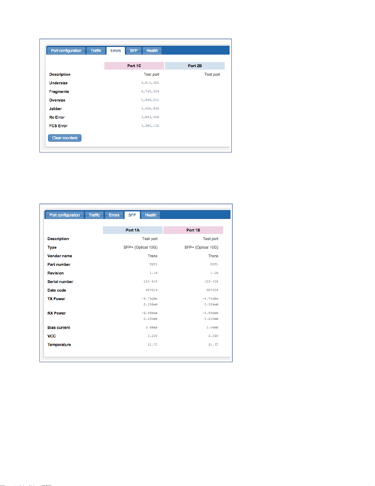
SmartNA-X 1G/10G Modular | Configuring Ports | 47
Figure 38: Errors statistics for ports 1C and 2B
Viewing SFP information
The SFP tab shows information about the transceiver and physical link for the selected SFP port(s).
Figure 39: SFP information for ports 1A and 1B
SmartNA-X™ 1G/10G User Guide 1.4 © 2015 Network Critical Solutions Limited
Page 48

48 | Moving Traffic With Maps | SmartNA-X 1G/10G Modular
Moving Traffic With Maps
Traffic is moved around the system by “maps” between source (ingress) and destination (egress) ports. To create a map in
the web UI, select the source port and drag to the destination port to create a line between the two ports. To create a map
in the CLI, use the set map command and specify the source and destination ports.
Creating maps in the web UI
In the web UI, add a map using a drag-and-drop action: move the pointer over your chosen source port, press and hold
your mouse button, move the pointer over your chosen destination port, and release the button.
When you add maps, they appear as lines on the port diagram. Arrows show the direction of traffic.
Chapter 5
Figure 40: Maps appear as lines on the port diagram
Map lines are drawn using different colours so you can tell them apart in complicated configurations. You can also move
the pointer over a map line, and the other maps will fade into the background.
Figure 41: Hover over a line to dim all other lines
You can aggregate traffic from multiple source ports to a single destination port. To create a many-to-one map, first select
all source ports you require, then drag from any of those ports and drop on the required destination port. This appears as a
single map connecting all of the ports.
Figure 42: A many-to-one (Aggregation) map
You can also replicate traffic and send copies to multiple destination ports. To create a one-to-many map, first select all
destination ports you require, then drag from the required source port onto any of the destination ports. This also appears
as a single map connecting all of the ports.
SmartNA-X™ 1G/10G User Guide 1.4 © 2015 Network Critical Solutions Limited
Page 49
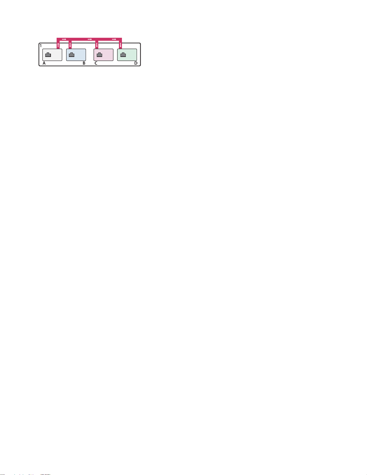
Figure 43: A one-to-many (Replication) map
SmartNA-X 1G/10G Modular | Moving Traffic With Maps | 49
SmartNA-X™ 1G/10G User Guide 1.4 © 2015 Network Critical Solutions Limited
Page 50
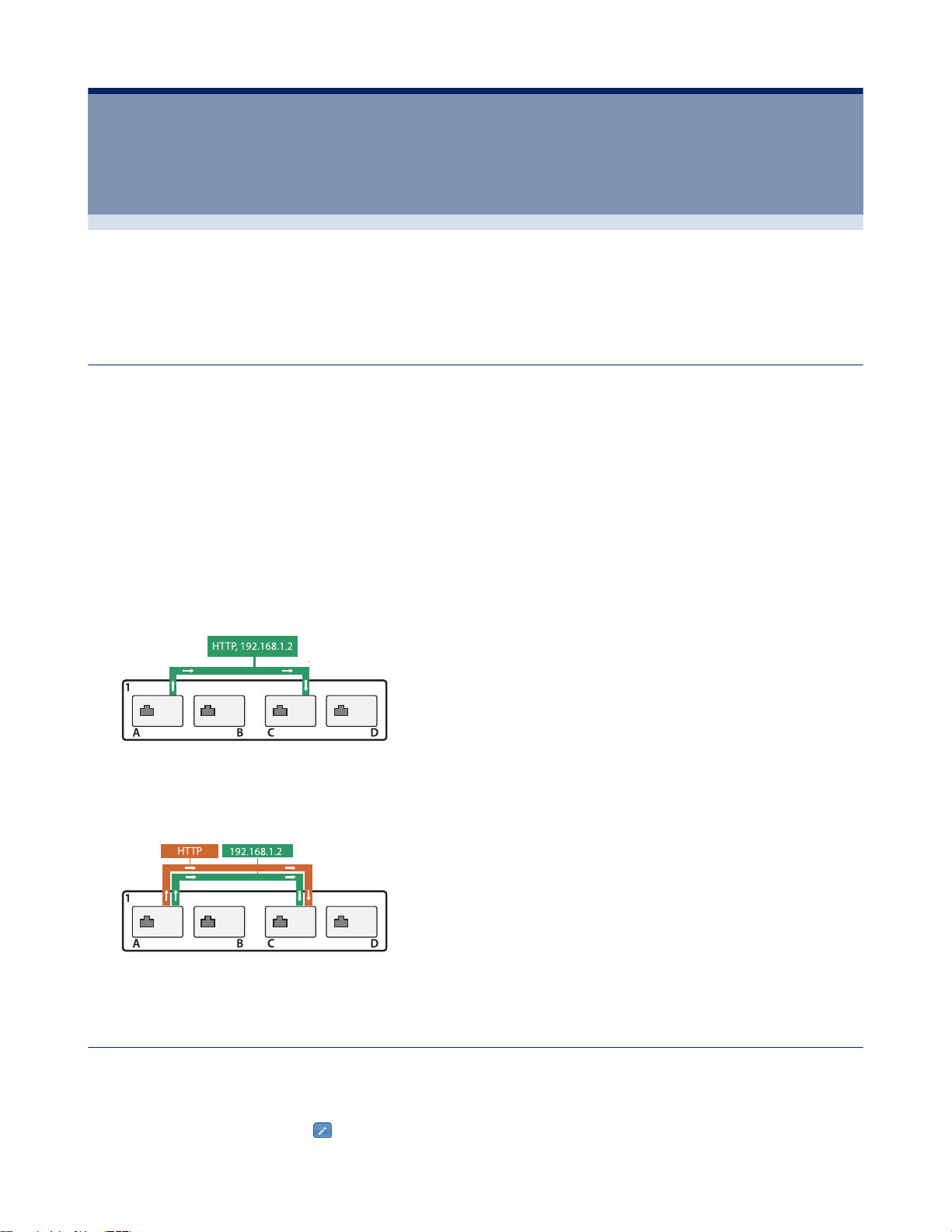
50 | Restricting Traffic with Filters | SmartNA-X 1G/10G Modular
Restricting Traffic with Filters
By default, a map will send a copy of all packets that enter its source port(s) out of its destination port(s). You can apply
“filters” to a map, so that only packets that match criteria you specify will pass.
Using filters
You use filters by first defining them and then applying them to a map. Filters can be combined or used in parallel to
create filtering rules that are able to match only those packets of interest from the entire data stream.
To use a filter, first define it by giving it a name and choosing the headers you want to filter for. After defining the filter,
add it to a map as either a require or an exclude filter:
Chapter 6
•
A require filter passes packets matching the filtering criteria and rejects packets which do not
•
An exclude passes packets which do not match the filtering criteria and rejects packets which do
When a filter has been applied its label appears beside the map, along with the word NOT if the filter is an exclude filter.
More complex filtering rules can be created by:
• Applying multiple filters to a single map, as shown in the following figure. This combination only passes packets
when all require filters and no exclude filters match (a logical AND).
• Applying multiple filters to several maps in parallel, as shown in the following figure. This combination passes
packets matching all required filters and no exclude filters for any one of the parallel maps even if that packet would
not pass some of the filters on the other maps that are created in parallel between the same ports (a logical OR).
Defining filters
Use the Add/Edit filter dialog to define filters.
1.
Click on the chassis and select the Filters tab.
2.
Click Add new filter, or click to edit an existing filter.
SmartNA-X™ 1G/10G User Guide 1.4 © 2015 Network Critical Solutions Limited
Page 51
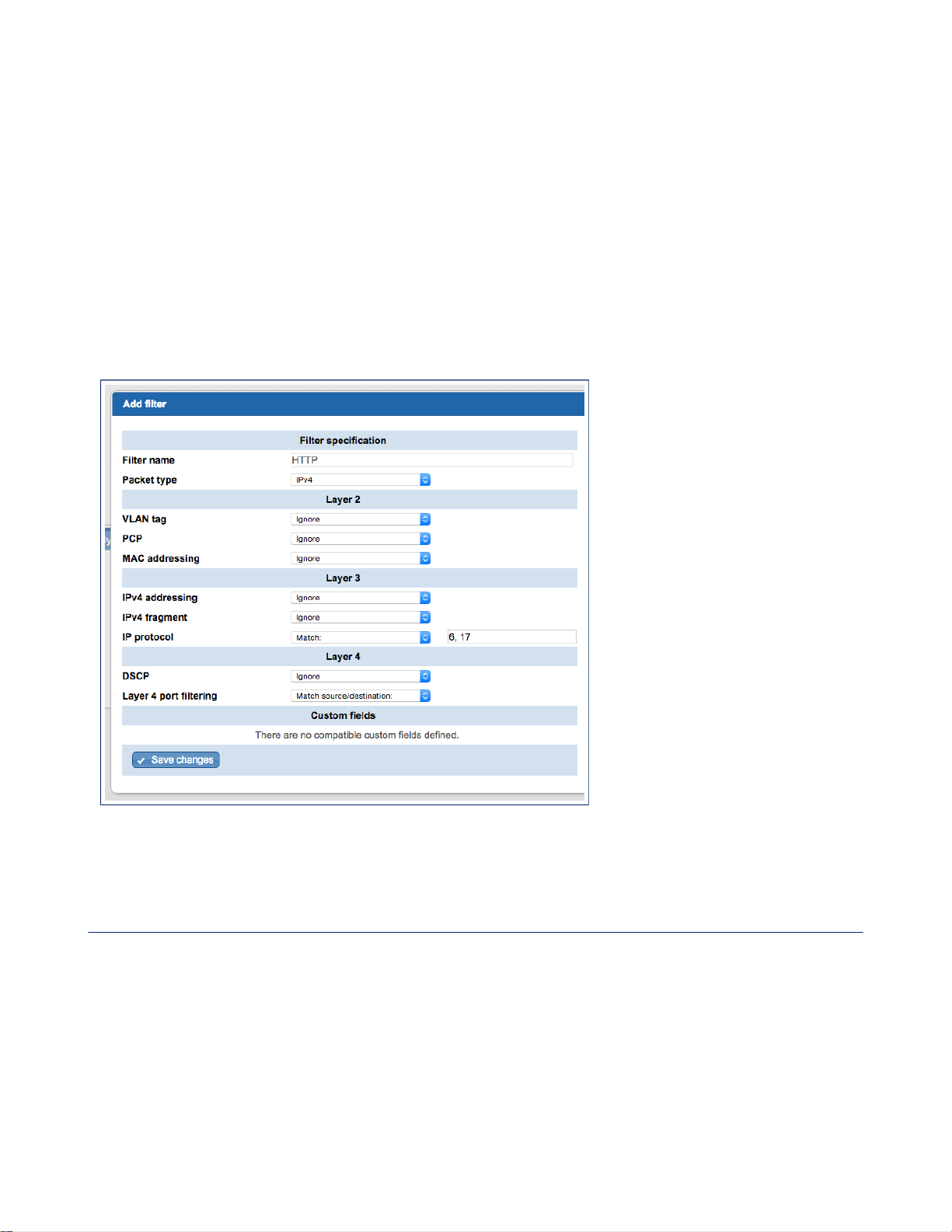
SmartNA-X 1G/10G Modular | Restricting Traffic with Filters | 51
3.
Enter a unique name for the filter. The name will be used to label maps where the filter is applied.
4.
From Packet type, select the packet type to filter on. The packet type corresponds approximately to the EtherType in
the packet header, and determines which additional layer 2, 3 and 4 filter fields are available.
5.
If required, refine the filter by specifying layer 2, 3 and 4 filtering criteria.
6.
If required, further refine the filter by adding a custom field. Only custom filters which match the packet type are
shown. Specify the values to match in the custom field.
A custom field is "in use" if at least one filter that is required or excluded by at least one map specifies a value to
match for that field.
7.
Click Add filter to finish defining the filter.
8.
Click Review/apply and review pending changes. To apply these changes to the system, click Apply changes or click
'X' to cancel.
Figure 44: Add filter dialog
Packet header filtering criteria
List of Layer 2, 3 and 4 headers available for packet filters. The system will prevent you from selecting headers which are
incompatible with the specified packet type. For instance, you cannot choose IPv6 packets and IPv4 fragments, or MPLS
and VLAN tags.
SmartNA-X™ 1G/10G User Guide 1.4 © 2015 Network Critical Solutions Limited
Page 52

52 | Restricting Traffic with Filters | SmartNA-X 1G/10G Modular
Table 2: Layer 2 headers
Header type Filtering options
VLAN tag Filters by VLAN number. The following caveats should be
noted when filtering by VLAN:
• When a filter is set to permit VID 1, untagged packets
will still be forwarded.
• Tagged packets with a VID of 1 will be forwarded
untagged.
• Tagged packets with a VID of 0 will be dropped.
You may use the following formats when specifying tags:
• 100—A single tag
• 100-110—An inclusive range
• 0/1—A value/mask pair (here: all even tags)
• 100, 150—Multiple tags Multiple tags may each use a
range or mask.
PCP Filters by Priority Code Point (user priority) from a VLAN
header.
You may use the following formats when specifying levels:
• 2—A single level
• 2-4—An inclusive range
• 0/1—A value/mask pair (here all even)
• 0,2—Multiple levels
MAC addressing Filters by MAC address. You may give either a single
specification to find packets where either the source or the
destination address matches, or separate specifications for
source and/or destination address.
You may use the following formats when specifying MAC
addressing:
• 01:23:45:67:89:ab—A single address
• 01:23:45:67:89:ab, 01:23:45:67:89:ac—Multiple
addresses
For ARP packets use source for the sender address and
destination for the target address.
MPLS top of stack label Filters by MPLS label. Where the MPLS header for a
packet contains multiple labels, this will test the top label
in the stack.
You may use the following formats when specifying labels:
• 100—A single label
• 100-110—An inclusive range
• 0/1—A value/mask pair (here: all even labels)
SmartNA-X™ 1G/10G User Guide 1.4 © 2015 Network Critical Solutions Limited
Page 53

SmartNA-X 1G/10G Modular | Restricting Traffic with Filters | 53
Header type Filtering options
• 100, 150—Multiple labels. Multiple labels may each
use a range or mask.
Table 3: Layer 3 headers
Header type Filtering options
IPv4 addressing Filters by IPv4 address. You may give either a single
specification, to find packets where either the source or the
destination address matches, or separate specifications for
source and/or destination address.
The following formats can be used to filter on a single IPv4
address, a range of addresses, or multiple addresses:
• 192.168.0.1—A single address
• 192.168.0.4-10—An inclusive range
• 192.168.0.*—Wildcard (192.168.0.0-255)
• 10.10.0.0/255.255.255.252—Mask (10.10.0.0-3)
• 10.10.0.3, 10.10.0.5—Multiple addresses Ranges and
wildcards may be used in any segment(s). Multiple
addresses may each use either ranges and wildcards or a
mask.
For ARP packets, use source for the sender address and
destination for the target address.
IPv4 fragment Filters by IPv4 fragments. Enter 0 not a fragment, or 1 is a
fragment.
IP protocol Filters by IP protocol number. Some commonly used IP
protocols numbers are:
• 1—ICMP
• 6—TCP
• 17—UDP
• 132—SCTP
The following formats can be used to specify a single
protocol, a range of protocols, or multiple protocols:
• 1—A single protocol
• 1-2—An inclusive range
• 0/1—A value/mask pair (here: all even protocols)
• 6, 17—Multiple protocols. Multiple protocols may each
use a range or mask.
IPv6 addressing Filters by IPv6 address. You may give either a single
specification to find packets where either the source or the
destination address matches, or separate specifications for
source and/or destination address.
The following formats can be used to filter on a single IPv6
address, a range of addresses, or multiple addresses:
SmartNA-X™ 1G/10G User Guide 1.4 © 2015 Network Critical Solutions Limited
Page 54

54 | Restricting Traffic with Filters | SmartNA-X 1G/10G Modular
Header type Filtering options
Table 4: Layer 4 headers
Header type Filtering options
• 2000:abcd:0:0:0:0:77:88—A single address
• 2000:abcd::77:88—A single address (eliding a single
run of zero segments) 2000:abcd::77:88-99—A range
address (inclusive)
• 2000::*—A wildcard (here: 2000::0-ffff )
• ::ffff:0:0/96—Prefix (any address starting
0:0:0:0:0:ffff )
• 2000::1, 2000::3—Multiple addresses may each use
either ranges and wildcards or prefix notation.
Ranges and wildcards may be used in any segment(s).
DSCP Filters DSCP number. Separate multiple DSCP numbers
with commas. The following formats are recognized:
• 10—a single code point
• 10–14—An inclusive range
• 0/1—a value/mask pair
• 10, 12, 14—multiple code points. Multiple code points
may each use a range or mask.
Layer 4 port filtering Filters by TCP/UDP port number when protocol number 6
(TCP) or 17 (UDP) is specified in Layer 3.
You may enter either a single specification to find packets
where either the source or the destination port matches, or
separate specifications for source and/or destination port.
Common TCP ports include:
• 80, 8080—HTTP
• 443—HTTPS
• 25—SMTP
• 20-21—FTP
• 989, 990—FTPS
• 22—SSH
• 23—Telnet
FIN, SYN, RST, PSH, ACK, URG, ECE, CWR Filters on the specified flag. For each flag the following
values may be set:
• 0—Flag not set
• 1—Flag set
ICMPtype Filter by ICMP type when filtering by ICMP packet
(protocol number 1). The following formats are recognised:
• 10—A single type
• 10–14—An inclusive range
SmartNA-X™ 1G/10G User Guide 1.4 © 2015 Network Critical Solutions Limited
Page 55

SmartNA-X 1G/10G Modular | Restricting Traffic with Filters | 55
Header type Filtering options
• 0/1—A value/mask pair (here: all even types)
• 10,12,14—Multiple types (use commas to separate
values, no spaces). Types may each use a range or
mask.
ICMPcode Filter by ICMP code when filtering by ICMP packet
(protocol number 1). The following formats are recognised:
• 10—A single code
• 10–14—An inclusive range
• 0/1—A value/mask pair (here: all even codes)
• 10,12,14—Multiple codes (use commas to separate
values, no spaces). Codes may each use a range or
mask.
Defining custom fields
You can use custom fields to filter on user-defined bytes (UDBs) in a packet header. The positioning of the custom field
within the packet is done by specifying an anchor and an offset value. The custom field itself can be up to 32 bits long.
Custom fields are applied by defining a filter of the same packet type, and specifying the custom field and UDBs that you
want to apply to the filter.
The following limitations apply for custom fields:
• No more than two underlying user-defined bytes anchored on start-of-packet can be used at once.
• No more than three underlying user-defined bytes can be used in conjunction with other filtering on IPv6 headers for
traffic from the same ingress port.
• No more than six underlying user-defined bytes can be used in total at any given time.
Here, "used" refers to custom fields that can actually affect passing traffic. Other custom fields may still be defined, and
filters may be defined using them, but these don't count toward the totals as long as the filters aren't applied to any maps.
1.
Click on the chassis and select the Custom fields tab.
2.
Click Add new custom field, or click to edit an existing custom field.
3.
Enter a unique name for the custom field. This name will be available in the Custom fields section in the filter
definition screen if the packet type you choose when defining the filter is compatible with the scope of any custom
fields you've defined.
4.
Enter details for the custom field:
• Scope—Select what types of filters may use the custom field, either all, all IP, IPv4, IPv6, ARP, or MPLS filters.
• Anchor—Select the starting position of the custom field in the packet, either at the start of the packet, at the start
of the layer 3 header, at the start of the layer 4 header, or at the start of the IPv6 extension header.
• Offset—Enter an offset position relative to the anchor position for the start of the field. You may enter offset
values of 0–1007 bits.
• Length—Enter a length for the field. The field length can be 1–32 bits. The offset plus the length of the field must
not exceed 1008 bits.
5.
Click Add custom field to finish defining the custom field.
6.
Click Review/apply and review pending changes. To apply these changes to the system, click Apply changes or click
'X' to cancel.
SmartNA-X™ 1G/10G User Guide 1.4 © 2015 Network Critical Solutions Limited
Page 56

56 | Restricting Traffic with Filters | SmartNA-X 1G/10G Modular
Applying filtering
To apply filtering, click on a map, select the relevant filter(s) from the list of defined filters, and choose either Ignore (let
all packets pass), Require (let only matching packets pass), or Exclude (let only non-matching packets pass).
1.
If you haven't done so already, set up the port mappings and define your filters.
2.
Click on a map. A list of defined filters is shown, as shown in the figure below.
3.
For each filter in the list, choose how you want filtering to be applied to the map:
• Ignore—(Default setting) Ignore this filter; let all packets pass.
• Require—Pass all matching packets and drop all non-matching packets.
• Exclude—Drop all matching packets and pass all non-matching packets.
4.
Click Review/apply and review pending changes. To apply these changes to the system, click Apply changes or click
'X' to cancel.
Figure 45: Map configuration dialog
SmartNA-X™ 1G/10G User Guide 1.4 © 2015 Network Critical Solutions Limited
Page 57

Chapter 7
Load Balancing
Load balancing
Load balancing allows a stream of traffic to be divided approximately evenly among multiple egress ports. The traffic
stream may come from a single ingress port or it may aggregate traffic from multiple ingress ports. Filtering may be
applied to remove unwanted traffic before the remainder is load balanced.
Note: Load balancing becomes available on SmartNA-X devices when an Aggregation & Filtering & Load
Balancing Feature Pack has been installed. Please contact your SmartNA-X reseller if you wish to install this
feature.
Load balancing on SmartNA-X
Traffic is divided among the load balancing ports by examining one or more headers in each packet from the stream. The
headers to be examined are user-configurable, with nine choices available initially.
The list of headers that may be used for load balancing is as follows:
• VLAN number
• MAC source address
• MAC destination address
• IPv4 source address
• IPv4 destination address
• IPv6 source address
• IPv6 destination address
• TCP/UDP source port
• TCP/UDP destination port
Egress ports for load balanced groups may still be used as destinations for the normal mapping and filtering functions. For
example, if tools are monitoring a protocol that has separate control and data channels, it is possible to load balance the
data channel traffic across a set of tool ports, but still to replicate all control channel data to all of those tool ports at the
same time.
Load-balancing scalability
SmartNA-X supports up to eight independent load balancing groups. The packet headers used to balance each group may
be different, but there is a limit of three headers per group.
There is no fixed limit on how many ingress ports may be aggregated to feed into a group, and there is no fixed limit on
how many egress ports a group’s traffic may be shared among. However, in practice the possible configurations will be
limited by system memory. Using many groups, many packet headers and many ports all at once is not possible. See Load
balancing – Best practices and limitations on page 58 for guidelines.
Load balancing consistency
Packets with the same header values are guaranteed to go to the same egress port. For example, if IPv4 source and
destination addresses are used for balancing, all traffic from address A to address B will be sent to the same egress port.
However, there is no guarantee traffic from address B to address A will also be sent to that same egress port.
SmartNA-X™ 1G/10G User Guide 1.4 © 2015 Network Critical Solutions Limited
Page 58

58 | Load Balancing | SmartNA-X 1G/10G Modular
Load balancing non-exclusivity
Egress ports for load balanced groups may still be used as destinations for the normal mapping and filtering functions
of SmartNA-X systems. For example, if tools are monitoring a protocol that has separate control and data channels, it is
possible to load balance the data channel traffic across a set of tool ports, but still to replicate all control channel data to all
of those tool ports at the same time.
Load balancing – Best practices and limitations
When using the load balancing feature, we recommend you follow our suggested best practises and take note of the
limitations that apply.
Best practices
The following best practises can be used to produce good results when setting up load balancing on SmartNA-X devices.
• Unless there is a compelling reason, you should restrict load balancing to one or two headers. Any more than two
headers requires considerably more system resources when running.
• If possible, select headers that will vary randomly for the expected traffic. In the majority of cases, two such headers
will provide effective balancing, and in some cases one may be enough. Note that incoming packets with the same
values for all of the headers selected for balancing will always be directed to the same egress port within the load
balanced group.
• If balancing across many ports or if the system has many other maps configured, if possible, use only a single load
balancing header to avoid overloading the system.
• Groups of two or four egress ports will give the most even output and will be the most memory-efficient.
• Where possible, apply filters to the ingress ports to restrict the stream to just those packets required for load balancing.
For example, if you wish to balance on headers below layers 2, that is, the various IP address and port headers, set up a
filter that restricts packets to just those headers.
Limitations
The following limitations apply when using load balancing on SmartNA-X devices.
• Load balancing needs variation in the selected header fields of incoming traffic to work properly. For example, if the
IPv4 source and destination addresses are selected, but all incoming traffic is between the same pair of addresses, the
balancing will not be effective. All packets would be sent to the same tool.
•
The balance is only an approximation, even with ideal incoming traffic. In general, it is not guaranteed that each of n
egress ports will receive exactly 1/n of the incoming packets. Some ports may receive 50% more packets than others
in the worst case. However, as long as two or more header fields are selected, a very even spread should be achieved if
the incoming traffic is suitable.
• There is no failsafe or standby capability for tools that fail. If a group balances traffic among, say, four tools and the
link to one tool goes down, those packets will be dropped. You may reconfigure the system to balance across the
remaining three tools, but this is not automatic.
• The system cannot balance traffic from one ingress port using IPv4 and IPv6 address fields together. This mirrors the
existing limitation on applying both IPv4 and IPv6 filters to maps from the same port.
Setting up load balancing
To set up load balancing, map source ports to a Load Balancer group and map the Load Balancer group to destination
ports. Configure the Load Balancer group with the headers that you want to balance against.
The following example load balances ports 1C, 1D, 2C and 2D from source ports 3A and 3B. It uses the packet's IPv4
source and Layer 4 port source for the load balancing data.
1.
Map port 3A to 3B and 3B to 3A.
SmartNA-X™ 1G/10G User Guide 1.4 © 2015 Network Critical Solutions Limited
Page 59
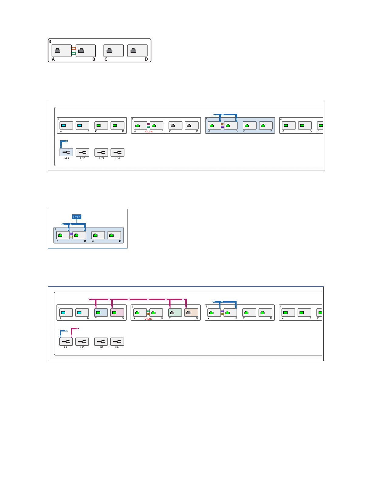
Figure 46: Map A and B ports
2.
Select ports 3A and 3B and then drag to load balancing group LB1.
Figure 47: Map ports 3A, 3B to LB1
SmartNA-X 1G/10G Modular | Load Balancing | 59
3.
Optionally add filters to remove unwanted packets prior to load balancing.
Figure 48: Add filters to remove unwanted packets
4.
Select ports 1C, 1D, 2C, 2D, then drag LB1 to any one of the selected ports.
Figure 49: Map LB1 to ports 1C, 1D, 2C, 2D
5.
Click on the Load Balancer Group (LB1).
6.
Choose up to three headers for the load balancing group. Note that to ensure an even load distribution, the headers
chosen must provide a variety of data for the expected packets.
SmartNA-X™ 1G/10G User Guide 1.4 © 2015 Network Critical Solutions Limited
Page 60

60 | Load Balancing | SmartNA-X 1G/10G Modular
Figure 50: Choose load balancing policy headers
7.
Click Review/apply and review pending changes. To apply these changes to the system, click Apply changes or click
'X' to cancel.
The complete set of CLI commands for the example configuration are shown below.
CONTROLLER>set map 3a to 3b
CONTROLLER>set map 3b to 3a
CONTROLLER>set map 3A 3B to LB1 require HTTP
CONTROLLER>set LB1 to 1C 1D 2C 2D
CONTROLLER>set lbheaders LB1 ipv4_src port_dest
CONTROLLER>commit
Committing maps
Committing filters
Committing load balance policy headers
SmartNA-X™ 1G/10G User Guide 1.4 © 2015 Network Critical Solutions Limited
Page 61

Chapter 8
Working with the V-Line Module
About V-Line modules
V-Line™ Modules allow inline tools to be integrated into a live network. The V-Line Module can be configured to bypass
a failed inline appliance to allow the network to continue running, or it can be configured to stop the live network if the
appliance is a critical component.
The V-Line Module provides V-Line™, Breakout, Aggregation and Egress TAP applications. Data passed through the
module ports preserves fragments and other illegal frames transparently. The V-Line module has flexible packet slicing
and packet injection capabilities, and supports standard port features for LFP, LMP, and TAP mode for the live network
ports (A, B) to preserve the network connections if the device loses power.
For safety, tools connected inline are continuously monitored for availability using heartbeat packets sent across the live
ports, passing through the inline tool along the way (heartbeat packets are removed by the system to prevent them being
transmitted onto the live network). If the heartbeat packets stop being received—meaning the inline tool is unavailable
—the system immediately switches into bypass mode and either connects the live ports to keep the network running or
disconnects the live ports from the network stopping all traffic on the network, depending on the bypass mode selected.
TAP mode on V-Line modules
TAP mode is available on V-Line modules on the AB port pair only. On these modules, the AB ports always have either
LFP or LMP enabled unless it is running in Egress mode. However, in V-Line mode, if the Reverse Bypass setting is
enabled this will break the AB link if there is a power outage. For more information, see About TAP mode on page 43.
V-Line module functionality
The V-Line Module provides three primary areas of functionality, although there is some overlap in the normal usage. The
three functions are:
• a V-Line facility with heartbeat based protection switching
• a general TAP mode allowing breakout and aggregation tap operations
• an egress packet slicing mode
V-Line mode
In V-Line mode the V-Line module is dedicated to supporting an inline tool that sees and can optionally filter all traffic
flowing on the main live network.
The inline tool health is permanently monitored by the card by sending special heartbeat packets to it and watching to
make sure the tool passes these packets correctly. The heartbeat packets are added to the streams sent to the C and D tool
ports and are removed from the streams received from the C and D tool ports. Heartbeat packets are never allowed onto
the live data network
If, for any reason the network tool stops passing heartbeat packets in either direction, the card will consider this a tool
failure. Depending on whether auto-bypass or reverse-bypass has been configured in the TAP, a failed tool will either be
automatically bypassed or the network will be stopped.
Optionally, packets received on the live network ports (A, B) can be passed to other modules in the system with or without
slicing the packets to a pre-set length. The slicing length can be set independently for each port.
SmartNA-X™ 1G/10G User Guide 1.4 © 2015 Network Critical Solutions Limited
Page 62
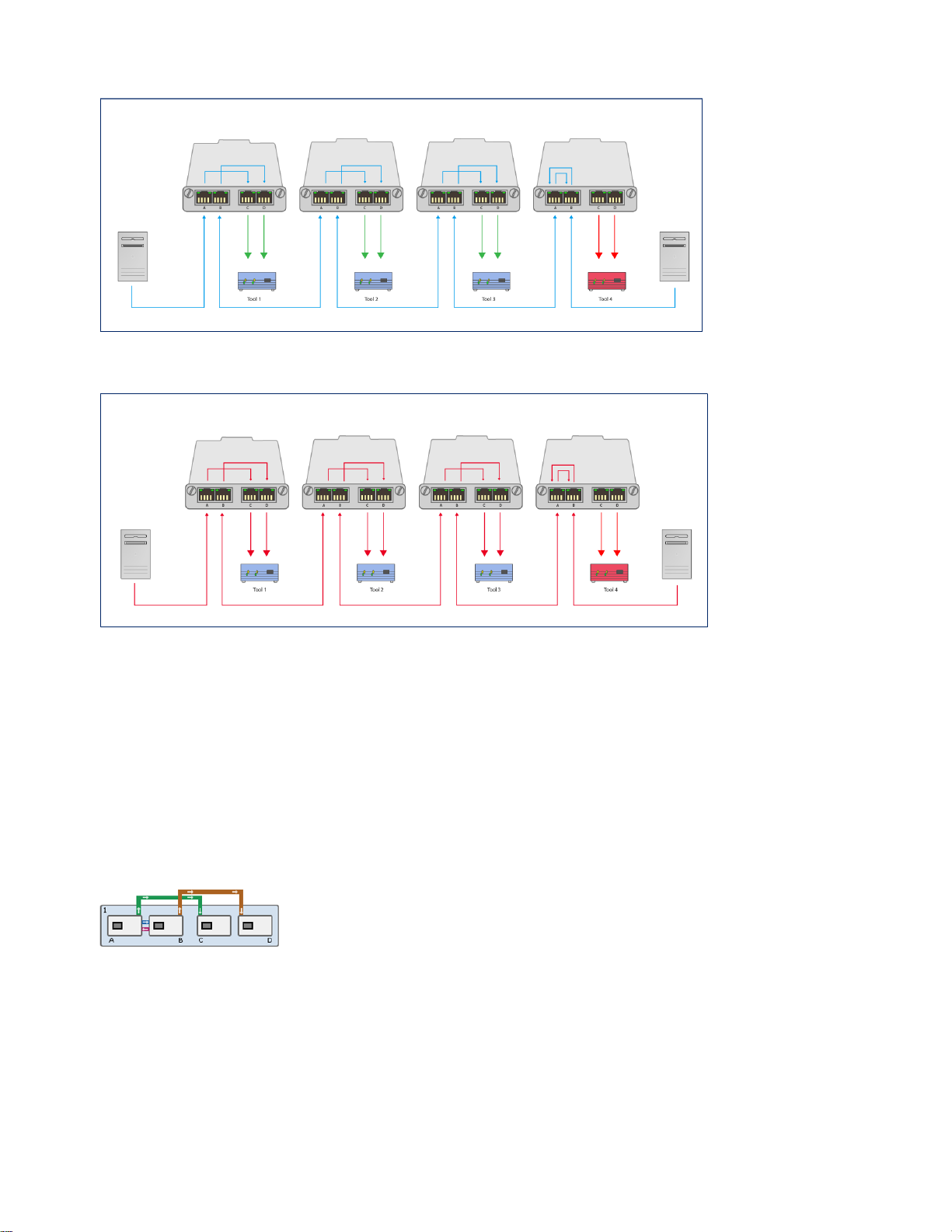
62 | Working with the V-Line Module | SmartNA-X 1G/10G Modular
Figure 51: V-Line auto-bypass mode: Tool 4 has failed and is being bypassed but Tools 1-3 continue to receive data.
Figure 52: V-Line reverse-bypass mode: Tool 4 has failed and the network has been stopped until Tool 4 is back online.
When operating in V-Line mode the AB port pair always operate as a TAP, with failsafe enabled. If required, you can
override this to disable the failsafe behaviour for that port pair by activating Reverse Bypass. For more information about
failsafe, see About TAP mode on page 43.
Breakout mode
V-Line Module Breakout mode (see the figure below) sends copies of traffic from the live network A and B ports to a
selectable combination of C and D ports with or without optional packet slicing. Packets received on the live network
ports (A, B) can be passed to other modules in the system. Filters are not supported on maps from the V-Line module to
other modules in the system
Figure 53: Breakout port mapping
When operating in Breakout mode, the AB port pair always operate as a TAP with failsafe enabled. If required, you can
override this to disable the failsafe behaviour for the AB port pair by activating Reverse Bypass. For more information
about failsafe, see About TAP mode on page 43.
SmartNA-X™ 1G/10G User Guide 1.4 © 2015 Network Critical Solutions Limited
Page 63
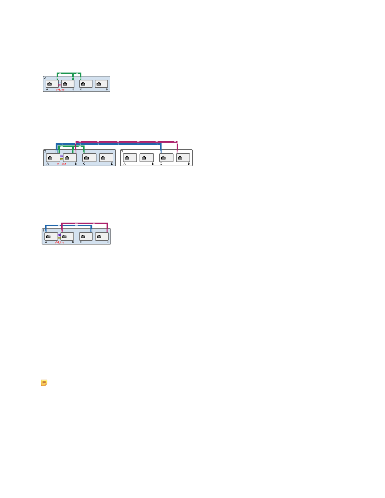
SmartNA-X 1G/10G Modular | Working with the V-Line Module | 63
Aggregation mode
V-Line Module Aggregation mode allows traffic from the live ports (A, B) to be copied and aggregated to tool ports (C,
D) in the same module or in a different mode, as shown in the following figures.
Figure 54: V-Line Aggregation mapping for A+B → C
Filters are not supported on maps from the V-Line module to other modules in the system.
Figure 55: Port Aggregation and cross-modular mapping
Aggregation mode also supports packet slicing (16–9216 bytes), allowing packet headers to be separated from the payload
to reduce the load on the network tools, and packet injection of low bandwidth data into the live network, as shown in the
following figure.
Figure 56: Port mapping for packet injection
When operating in Aggregation mode the AB port pair always operate as a TAP, with failsafe enabled. If required, you
can override this to disable the failsafe behaviour for that port pair by activating Reverse Bypass. For more information
about failsafe, see About TAP mode on page 43.
Egress mode
The Egress mode allows traffic to be mapped onto the V-Line module from other ports on the system (via the internal
backplane) and taken out of the front ports, optionally slicing it first.
All four ports (A, B, C and D) work the same way in this mode, although the slicing configuration can be adjusted
individually for each port. Note that there is no traffic coming onto the V-Line card from the front ports at all in Egress
mode, so mapping from the front ports is not permitted.
Multiple system ports can be mapped (aggregated) to any one Egress port, but traffic filtering on the maps should be used
to ensure that the overall limit of 1Gbps of traffic per egress port is not exceeded.
Note: The slicing facility is useful for reducing the number of bits that are to be sent to a network tool for
processing and/or storing. However, slicing is not intended as a replacement for the correct application of filters in
reducing aggregated traffic to prevent overloading a port.
SmartNA-X™ 1G/10G User Guide 1.4 © 2015 Network Critical Solutions Limited
Page 64

64 | Working with the V-Line Module | SmartNA-X 1G/10G Modular
Configuring the V-Line operational mode
Depending on how you want to integrate your network tools into the TAP, V-Line Modules can be configured to operate
in V-Line mode, Breakout mode, Aggregation mode, or Egress mode.
Configure V-Line mode
1.
Click on the V-Line module you wish to configure and select the V-Line tab.
2.
From V-Line mode, select V-Line. The V-Line Module: V-Line mode dialog is displayed (see the figure below) and
the ports are automatically configured for V-Line mode, as shown in the following figure.
Figure 57: Port mapping for V-Line mode
3.
Enter the values for the parameters:
• Bypass mode—Select the bypass mode to activate when heartbeat packets are not received from a connected tool.
The options are:
•
Auto—Enables automatic bypass mode. Traffic and heartbeats are sent to the tool. If a tool failure is detected
(no heartbeats received from the tool), the tool ports are disconnected to isolate the tool from the network;
that is, the tool is isolated from the live network with the network continuing to pass traffic. The tool remains
isolated even in the case of a power failure and stays isolated when power is returned until either the tool is
seen to be working properly or the card configuration is changed
•
Forced—Enables forced bypass mode. Traffic and heartbeats are still sent to the tool ports, but the live ports
are directly connected and the tool output is ignored.
•
Reverse—Enables reverse bypass mode. When a tool failure is detected (no heartbeats received from the tool),
the live ports are disconnected to isolate the link; that is, the live network and all traffic flowing along it is
stopped. The link remains isolated even in the case of a power failure and stays isolated when power is returned
until either the tool is seen to be working properly or the card configuration is changed.
• Heartbeat rate (ms)—Enter heartbeat packet transmit rate in milliseconds. Heartbeat packets are never allowed
onto the live data network. You may enter values from 1–1000 ms. The heartbeat default rate is 50 ms.
• Heartbeat timeout (ms)—Enter the heartbeat loss detection time in milliseconds. The system will bypass an inline
tool if no heartbeat packets are received within this period. The heartbeat default timeout is 250 ms.
• Heartbeat packet—Optionally enter a custom heartbeat packet or leave the text box blank to use the default
heartbeat packet, which is a broadcast ARP packet. The heartbeat packet must be capable of being passed by
your network tool. The data for the custom heartbeat packet must be provided as a string of 32 to 3072 hex digits.
Punctuation and whitespace are ignored. The packet data will be sent verbatim and must therefore include any
required FCS checksum at the end. The same packet data will be used for the heartbeat in each direction.
• Slicing (A ingress)—Enter a value for the packet slicing size for Port A ingress packets, or leave blank to forward
packets unsliced. This setting only affects ingress packets that are copied from the A/B ports to ports on other
cards. Minimum slicing value is 16 Bytes, maximum slicing value is 9216 Bytes.
Note: Slicing applies to the ingress traffic mapped to other system ports, not to the Live Ports themselves.
• Slicing (B ingress)—Enter a value for the packet slicing size for Port B ingress packets, or leave blank to forward
packets unsliced. This setting only affects ingress packets that are copied from the A/B ports to ports on other
cards. Minimum slicing value is 16 Bytes, maximum slicing value is 9216 Bytes.
SmartNA-X™ 1G/10G User Guide 1.4 © 2015 Network Critical Solutions Limited
Page 65

SmartNA-X 1G/10G Modular | Working with the V-Line Module | 65
Note: Slicing applies to the ingress traffic mapped to other system ports, not to the Live Ports themselves.
4.
Configure port communication settings, noting the following requirements for effective port communications:
Mapping to other TAP modules
If a V-Line module is mapped to another TAP module, the V-Line module ports must be set to 1G bps.
Live ports
If operating in V-Line, Aggregation or Breakout mode, the V-Line module live ports (A and B) must have
matching communication settings (same speed, duplex and MDI settings).
Tool ports
If operating in V-Line or Breakout mode, the V-Line module tool ports (C and D) must have the same
communication settings as the live ports (A and B) .
5.
Click Review/apply and review pending changes. To apply these changes to the system, click Apply changes or click
'X' to cancel.
Figure 58: V-Line Module: V-Line mode settings dialog
Configure Breakout mode
1.
Click on the V-Line module you wish to configure and select the V-Line tab.
2.
From V-Line mode, select Breakout. The V-Line Module: Breakout mode dialog is displayed (see the figure below).
Figure 59: V-Line Module: Breakout mode settings dialog
3.
Enter values for the parameters.
SmartNA-X™ 1G/10G User Guide 1.4 © 2015 Network Critical Solutions Limited
Page 66
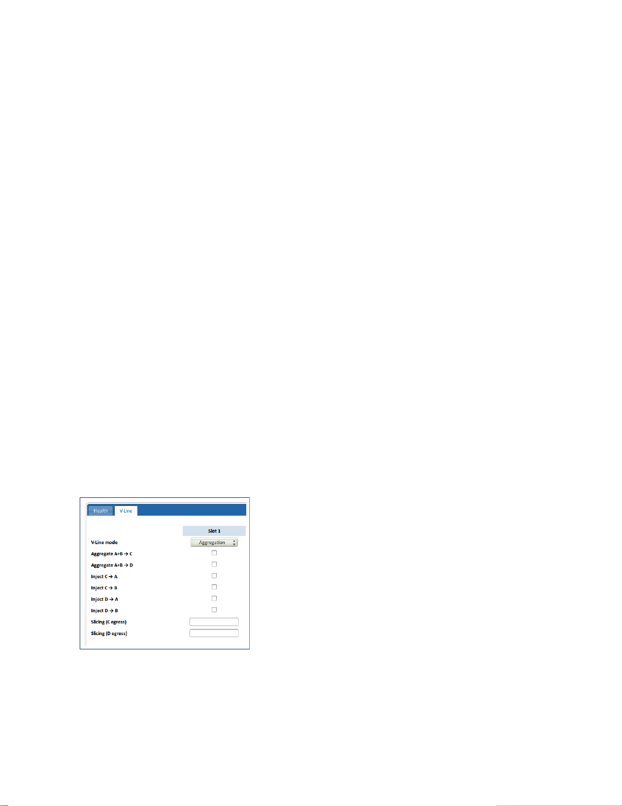
66 | Working with the V-Line Module | SmartNA-X 1G/10G Modular
• Breakout A → C—Select the check box to add a breakout mapping from Port A to Port C. Traffic received on A
is copied to C.
• Breakout B → D—Select the check box to add a breakout mapping from Port B to Port D. Traffic received on B is
copied to D.
• Slicing (A ingress)—Enter a packet slicing size for ingress traffic received on Port A. Minimum slicing size is 16
Bytes and maximum slicing size is 9216 Bytes. Leave blank or enter 0 to keep packets unsliced. This setting only
affects ingress packets that are copied from the A/B ports to ports on other cards.
• Slicing (B ingress)—Enter a packet slicing size for ingress traffic received on Port B. Minimum slicing size is 16
Bytes and maximum slicing size is 9216 Bytes. Leave blank or enter 0 to keep packets unsliced. This setting only
affects ingress packets that are copied from the A/B ports to ports on other cards.
• Slicing (C egress)—Enter a packet slicing size for egress traffic sent from Port C. Minimum slicing size is 16
Bytes and maximum slicing size is 9216 Bytes. Leave blank or enter 0 to keep packets unsliced.
• Slicing (D egress)—Enter a packet slicing size for egress traffic sent from Port D. Minimum slicing size is 16
Bytes and maximum slicing size is 9216 Bytes. Leave blank or enter 0 to keep packets unsliced.
4.
Configure port communication settings, noting the following requirements for effective port communications:
Mapping to other TAP modules
If a V-Line module is mapped to another TAP module, the V-Line module ports must be set to 1G bps.
Live ports
If operating in V-Line, Aggregation or Breakout mode, the V-Line module live ports (A and B) must have
matching communication settings (same speed, duplex and MDI settings).
Tool ports
If operating in V-Line or Breakout mode, the V-Line module tool ports (C and D) must have the same
communication settings as the live ports (A and B) .
5.
Click Review/apply and review pending changes. To apply these changes to the system, click Apply changes or click
'X' to cancel.
Configure Aggregation mode
1.
Click on the V-Line module you wish to configure and select the V-Line tab.
2.
From V-Line mode, select Aggregation. The V-Line Module: Aggregation mode dialog is displayed (see the figure
below).
Figure 60: V-Line Module: Aggregation mode settings dialog
3.
Enter the values for the parameters.
• Aggregate A+B → C—Select the check box to merge Ports A and B and send to Port C.
• Aggregate A+B → D—Select the check box to merge Ports A and B and send to Port D.
SmartNA-X™ 1G/10G User Guide 1.4 © 2015 Network Critical Solutions Limited
Page 67

SmartNA-X 1G/10G Modular | Working with the V-Line Module | 67
• Inject C → A—Select the check box to inject traffic on Port C into Port A.
When injecting packets back into the live network, the maximum packet size (MTU) supported is 1536 bytes.
• Inject C → B—Select the check box to inject traffic on Port C into Port B.
• Inject D → A—Select the check box to inject traffic on Port D into Port A.
• Inject D → B—Select the check box to inject traffic on Port D into Port B.
• Slicing (C egress)—Enter a packet slicing size for egress traffic sent from Port C.
Minimum slicing size is 16 Bytes and Maximum slicing size is 9216 Bytes. Leave blank or enter 0 to keep packets
unsliced.
• Slicing (D egress)—Enter a packet slicing size for egress traffic sent from Port D.
Minimum slicing size is 16 Bytes and Maximum slicing size is 9216 Bytes. Leave blank or enter 0 to keep packets
unsliced.
4.
Configure port communication settings, noting the following requirements for effective port communications:
Mapping to other TAP modules
If a V-Line module is mapped to another TAP module, the V-Line module ports must be set to 1G bps.
Live ports
If operating in V-Line, Aggregation or Breakout mode, the V-Line module live ports (A and B) must have
matching communication settings (same speed, duplex and MDI settings).
Tool ports
If operating in V-Line or Breakout mode, the V-Line module tool ports (C and D) must have the same
communication settings as the live ports (A and B) .
5.
Click Review/apply and review pending changes. To apply these changes to the system, click Apply changes or click
'X' to cancel.
Configure Egress mode
1.
Click on the V-Line module you wish to configure and select the V-Line tab.
2.
From V-Line mode, select Egress. The V-Line Module: Egress mode dialog is displayed (see the figure below).
3.
Enter the values for the parameters.
• Slicing (A egress)—Enter a packet slicing size for egress traffic sent from Port A.
Minimum slicing size is 16 Bytes and maximum slicing size is 9216 Bytes. Leave blank or enter 0 to keep packets
unsliced.
• Slicing (B egress)—Enter a packet slicing size for egress traffic sent from Port B.
Minimum slicing size is 16 Bytes and maximum slicing size is 9216 Bytes. Leave blank or enter 0 to keep packets
unsliced.
• Slicing (C egress)—Enter a packet slicing size for egress traffic sent from Port C.
Minimum slicing size is 16 Bytes and maximum slicing size is 9216 Bytes. Leave blank or enter 0 to keep packets
unsliced.
• Slicing (D egress)—Enter a packet slicing size for egress traffic sent from Port D.
Minimum slicing size is 16 Bytes and maximum slicing size is 9216 Bytes. Leave blank or enter 0 to keep packets
unsliced.
4.
Configure port settings as required. Note that V-Line ports must be set to 1G bps if they are mapped to other TAP
modules.
5.
Click Review/apply and review pending changes. To apply these changes to the system, click Apply changes or click
'X' to cancel.
SmartNA-X™ 1G/10G User Guide 1.4 © 2015 Network Critical Solutions Limited
Page 68

68 | Working with the V-Line Module | SmartNA-X 1G/10G Modular
Figure 61: V-Line Module: Egress mode
SmartNA-X™ 1G/10G User Guide 1.4 © 2015 Network Critical Solutions Limited
Page 69

Chapter 9
Working with the Intelligent Packet Processor (IPP) Module
The SmartNA-X Intelligent Packet Processor (IPP) module (model types 5701) is designed to facilitate header removal
from and payload manipulation of data packets received via multiple tunnelling protocols prior to onward processing
within the system.
Physical
The IPP module operates as a four-port 1G bps module in slots 2, 3 and 4, and a four-port 10G bps module or four-port
1G bps module in slots 1 and R (the rear slot).
No physical ports are present on the front panel – traffic flows are internal to the SmartNA-X and maps are created to and
from other ports in the system in the usual way.
There are two LEDs on the front panel: the upper one flashes to indicate traffic present on the card and the lower one
flashes to indicate a header match has been detected.
Overview of the IPP operation
The IPP module works by analysing a packet to identify specific headers. Once found these headers can be optionally
stripped from the packet or modified, leaving the rest of the packet available for further processing. Up to eight headers
can be looked for and processed per packet .
The IPP module has no external ports of its own. Instead, packets are sent to it from other SmartNA-X modules, before
being returned to the chassis for onward forwarding.
Maps are used in the normal way to direct traffic into the IPP module and then from the IPP module post processing to an
egress port to a tool. Maps can be configured using the web UI or the CLI.
In addition to header manipulation and removal, the IPP module can slice the payload to a pre-defined length before
sending the packet back into the SmartNA-X system.
It is also possible to obfuscate the payload by changing all bytes beyond a specified point to be a user defined value.
Detailed operation of the IPP module
A match (compare) is carried out on the bits in the first 120 bytes (a bit mask compare) of the packet. If a match is found,
actions can be applied to each byte within the first 120 bytes. Optionally, packets egressing from a port can be sliced to a
given length.
Matches
Match bits have a 1:1 correspondence with the bits of a packet. Bits are counted in network order from zero starting from
the first transmitted/received bit of the MAC destination address in the Ethernet header, and ignoring the preamble. Within
the field, the start bit is the first in network order, and takes the most significant bit of the value.
SmartNA-X™ 1G/10G User Guide 1.4 © 2015 Network Critical Solutions Limited
Page 70

70 | Working with the Intelligent Packet Processor (IPP) Module | SmartNA-X 1G/10G Modular
The system allows for the creation of custom Matches, where the start bit, width and value are specified by the user, and
pre-configured 'named Matches', where the user just needs to specify the name of a Match and the system automatically
sets the start bit, width and value.
Note: Overlapping Match fields are not permitted.
Actions
Once a match has been found any one of the following actions can be applied to each byte within the first 120 bytes.
Delete a byte
Remove a specified byte from the packet header.
Replace a byte
Change a specified byte in the packet header to a different value.
Invert bit(s) within a byte (logical XOR)
Change any or all bits within a byte to the opposite value.
Set bit(s) within a byte (logical OR)
Change any or all bits within a byte to have the value 1.
Clear bit(s) within a byte (logical AND)
Change any or all bits within a byte to have the value 0.
Truncate all beyond a specified byte
Delete all bytes beyond a specified byte.
Obfuscate all beyond a specified byte
Change all bytes beyond a specified byte to a new value.
Pass all beyond a specified byte
Pass the rest of the packet without further processing further.
Note that only one of the actions is available on each byte. For example, in a byte you can't set some bits and clear others.
The following limits apply to IPP actions:
• Only the first 120 bytes of a packet support an action.
• The first 119 bytes may have any action associated with them.
• The 120th byte only supports truncate or pass.
• The start-bit of a delete or truncate action must begin after the MAC addresses; that is, no less than the 12th byte.
• The value associated with XOR, AND, OR, Replace and Obfuscate is limited to 0-255.
• The value associated with Delete is limited to affecting no further than the first 119 bytes.
Transforms
The combination of a set of one or more Matches and a set of one or more Actions is known as a Transform. Transforms
allow you to identify certain bit values within the packet header, and change byte values when matching bits have been
identified.
The Matches and Actions can operate on entirely different parts of the packet header, and there may be a different number
of Matches than there are Actions. When several Matches are specified in a Transform, they all must match for the
associated Action or Actions to be performed on the packet header.
Transforms are applied to ports. Each port can have up to eight Transforms applied to it. In cases where several
Transforms match a packet, the Transform with the highest priority (lowest Transform number) is actioned. Thus, only
one Transform per packet can ever be actioned.
After a Transform has been performed, the packet CRC is recalculated to be correct for the modified packet.
See Configuring the IPP module on page 72 for a step-by-step guide to setting up a Transform.
SmartNA-X™ 1G/10G User Guide 1.4 © 2015 Network Critical Solutions Limited
Page 71

SmartNA-X 1G/10G Modular | Working with the Intelligent Packet Processor (IPP) Module | 71
Packet slicing
In addition to transforming bytes within the packet header, the IPP module can also be used to slice packets egressing
from a port to a given byte length. The slice size includes the CRC, which is recalculated to match the modified packet.
Slicing is optional and is not dependent on matching bits within the packet. Rather, it is applied to all packets egressing
from a port, whether they have been matched by a Transform or not.
To set up packet slicing on an IPP module port, use the set port packetprocessor slicing command. The following
example slices packets to 756 byes egressing from Port 1A:
CONTROLLER>select slot 1
SLOT1>set port A packetprocessor slicing 756
Committing changes after configuring the IPP module
Any changes made to the IPP module remain pending in memory only until the commit command has been entered.
This is done to prevent putting the system into a potentially unstable state while the IPP module is being configured. It
also allows you to back out of any changes made, if required, by entering the packetprocessor cancel command.
The general advise when setting up the IPP module is to make all required configuration changes, and then use the
commit command to reconfigure the system.
SmartNA-X™ 1G/10G User Guide 1.4 © 2015 Network Critical Solutions Limited
Page 72
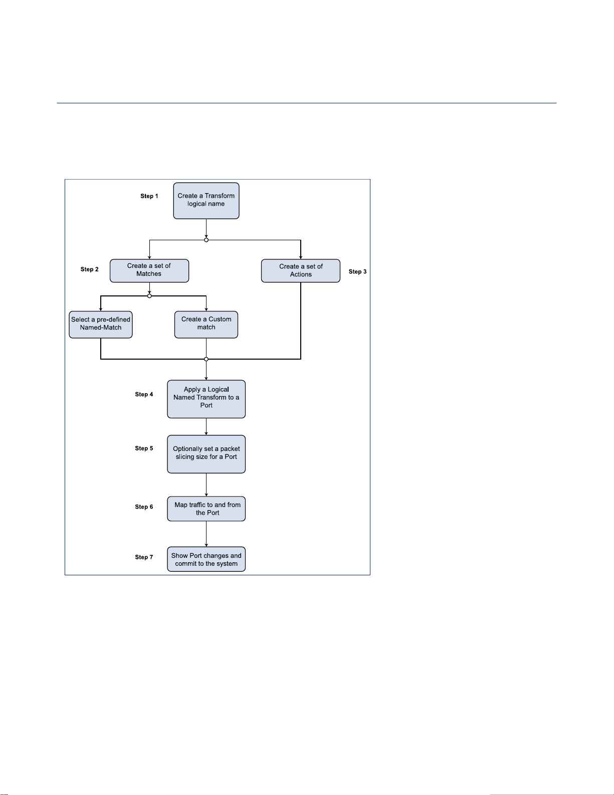
72 | Working with the Intelligent Packet Processor (IPP) Module | SmartNA-X 1G/10G Modular
Configuring the IPP module
Configure the IPP module by creating a Transform and a set of Matches and Actions. Add the Matches and Actions to the
Transform and apply it to a port. Up to eight Transforms can be applied per port. Map the port to other ports in the system,
and commit your changes to the system to make them live.
The following flow diagram summarizes the steps for configuring the IPP module.
Figure 62: Flow diagram for configuring the IPP module
The following steps provide detailed instructions and example commands for configuring the IPP module.
Step 1: Create a Transform logical name
The first step when configuring the IPP module is to create a Transform logical name. Once a Transform has been created,
Matches and actions can be assigned to it and applied to a port. Multiple Transforms, each with different Matches and
actions, can be created, and each port can have up to eight Transforms (numbered 1-8) applied to it. Transforms have
global significance within the system and are not limited to any particular IPP module in the chassis. So if you have more
than one IPP module, the same Transform can be applied to ports on either.
The following example creates a Transform named "remove v2 header":
SmartNA-X™ 1G/10G User Guide 1.4 © 2015 Network Critical Solutions Limited
Page 73

SmartNA-X 1G/10G Modular | Working with the Intelligent Packet Processor (IPP) Module | 73
CONTROLLER>create packetprocessor transform "remove v2 header"
Step 2: Create a set of Matches
The next step is to add one or more Matches to the Transform. A Match consists of a start-bit, a length, and a value. You
can specify these using custom values, or you can use one of the preset Matches that are built into the system, where
preset values for the start, length and value are used (see Packet Processor Preset Matches).
A Match works by examining the packet header for the value at the specified starting position and length. If a match is
found, the Action assigned to the Transform will be taken; if no match is found then the Action is ignored. You may add
multiple Matches to a Transform, but all the Matches must match for the Action to be taken.
The following example assigns a custom Match to the Transform named "remove v2 header":
CONTROLLER>set packetprocessor transform "remove v2 header" match 17 1 1
In the following example, the predefined Match named "Ethertype-C-tag" is assigned to the "remove v2 header"
Transform:
CONTROLLER>set packetprocessor transform "remove v2 header" named-match Ethertype-C-tag
Step 3: Create a set of Actions
The third step is to add to the Transform a set of Actions that will be taken if a Match is found. The following Actions are
available:
Delete a byte
Remove a specified byte from the packet header.
Replace a byte
Change a specified byte in the packet header to a different value.
Invert bit(s) within a byte (logical XOR)
Change any or all bits within a byte to the opposite value.
Set bit(s) within a byte (logical OR)
Change any or all bits within a byte to have the value 1.
Clear bit(s) within a byte (logical AND)
Change any or all bits within a byte to have the value 0.
Truncate all beyond a specified byte
Delete all bytes beyond a specified byte.
Obfuscate all beyond a specified byte
Change all bytes beyond a specified byte to a new value.
Pass all beyond a specified byte
Pass the rest of the packet without further processing further.
In the following example, an action applied to the Transform named "remove v2 header" will exclusive OR the 48th byte
of the packet with 30.
CONTROLLER>set packetprocessor transform "remove v2 header" action 48 xor 30
Step 4: Apply the logically named Transform to a port
In this step we apply the Transform to a port, with a priority setting. Each port has eight priority levels (1-8 with 1 being
the highest priority), and each level can have one Transform applied to it. If multiple Transforms match, the Transform
with the highest priority is actioned and the rest are ignored.
In the following example, port 1A has the Transform named "remove v2 header" applied with priority 7:
SmartNA-X™ 1G/10G User Guide 1.4 © 2015 Network Critical Solutions Limited
Page 74

74 | Working with the Intelligent Packet Processor (IPP) Module | SmartNA-X 1G/10G Modular
CONTROLLER> select slot 1
SLOT1>set port A packetprocessor transform 7 "remove v2 header"
Step 5: Optionally set a packet slicing size to a port
The next step is to optionally slice packets egressed from a IPP port to a given length. When slicing is applied, all packets
egressed will be no longer than the specified Slice length, which is defined in bytes and includes the CRC bytes.
In the following example, packets egressed from port 1A are sliced to 756 bytes:
SLOT1>set port A packetprocessor slicing 756
Step 6: Map traffic to and from the port
The penultimate step is to map the IPP ports to and from other ports in the chassis. Since the IPP module has no physical
ports, packets can only enter and leave the module by mapping to/from other modules in the chassis.
SLOT1>set map 4a to 1a
SLOT1>set map 1a to 4b
Step 7: Commit changes to the system
The final step to setting up the IPP module is to review the pending port configuration changes. If the changes are correct,
commit them to update the system configuration, otherwise use the cancel packetprocessor command to discard them.
SLOT1>show port A
port type : Packet processor
slicing : 756
transforms :
7: "remove v2 header"
SLOT1>commit
Example Transforms
The GRE packet arrives with a delivery (IP) header and GRE header that we want to strip, leaving the encapsulated IP
header and payload.
IPv4 headers and GRE headers have variable size. A single Transform detects and strips headers of a specific size. Up to 8
transforms could be used to detect and strip headers of 8 different sizes.
Standard transforms are provided for cases where the transport header is IPv6 or a 20 byte IPv4.
Removing delivery header and 3 word GRE header from an untagged IPv4 or IPv6 packet
A Transform to match and remove the GRE or PPTP GRE header using Key and Sequence fields (but not Checksum or
Acknowledgement. This applies to untagged IPv4 packets.
Matches:
EtherType-IPv4
IPv4-IHL=5
GRE-KS-L=3-IPv4
The required action is to delete the 5 word IPv4 header and the 3 word GRE header, a total of 32 contiguous bytes.
Action:
action 112 delete 32
To do the same to IPv6 packets we need a second transform.
SmartNA-X™ 1G/10G User Guide 1.4 © 2015 Network Critical Solutions Limited
Page 75

SmartNA-X 1G/10G Modular | Working with the Intelligent Packet Processor (IPP) Module | 75
Matches:
EtherType-IPv6
Version-IPv6
GRE-KS-L=3-IPv6
Delete the 10 word IPv6 header and 3 word GRE header:
Action:
action 112 delete 52
Saving and applying a Transform to remove delivery header and 8 byte GRE header from untagged 20
byte IPv4 packets
create packetprocessor transform "IPv4:20 remove GRE:8"
set packetprocessor transform "IPv4:20 remove GRE:8" named-match "EtherType-IPv4"
set packetprocessor transform "IPv4:20 remove GRE:8" named-match "IPv4-IHL=5"
set packetprocessor transform "IPv4:20 remove GRE:8" named-match "GRE-KS-L=3-IPv4"
set packetprocessor transform "IPv4:20 remove GRE:8" action 112 delete 32
set port a packetprocessor transform 1 "IPv4:20 remove GRE:8"
SmartNA-X™ 1G/10G User Guide 1.4 © 2015 Network Critical Solutions Limited
Page 76
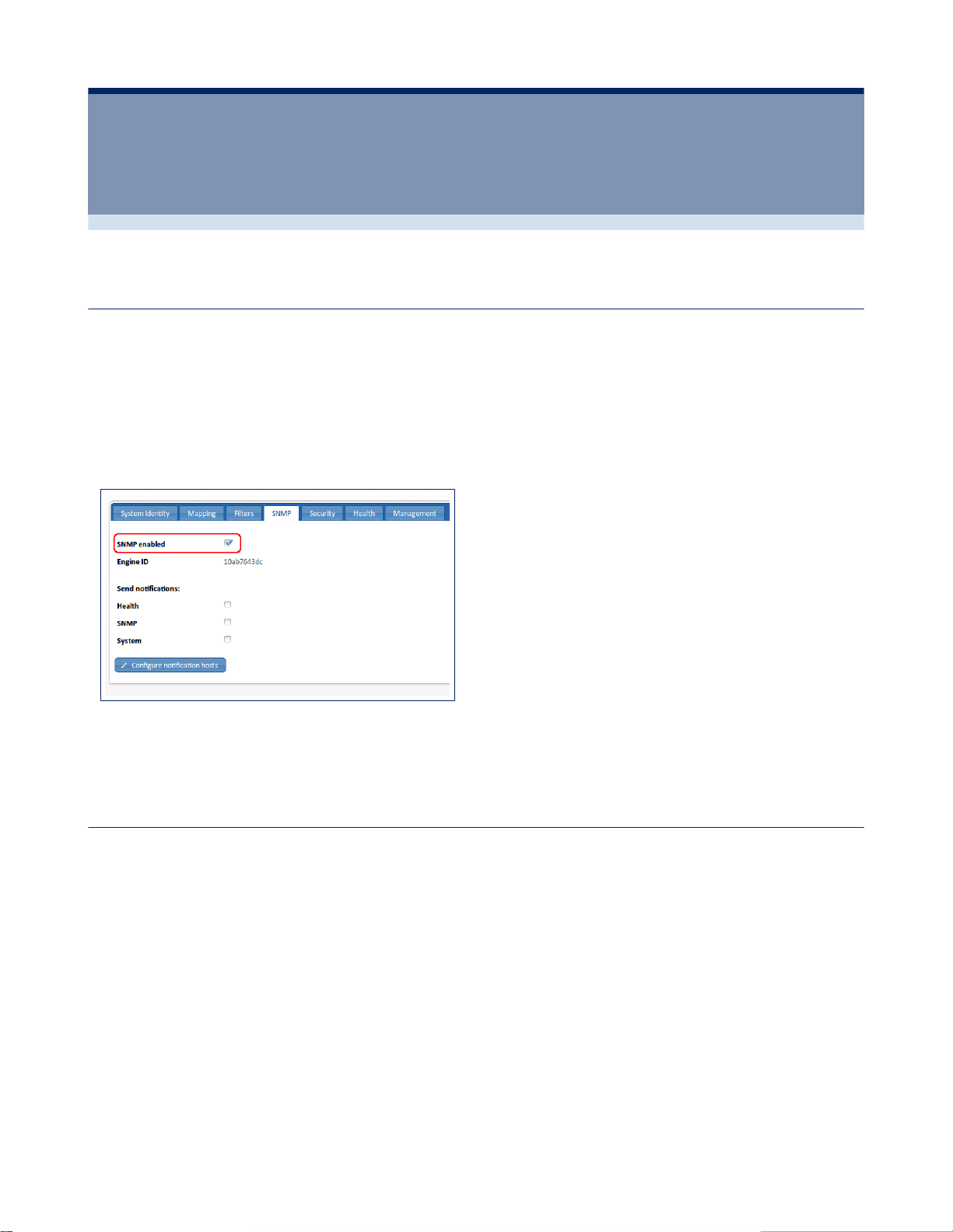
76 | SNMP | SmartNA-X 1G/10G Modular
SNMP
Enabling SNMP
The SNMP agent on this device is disabled by default. Enable the agent to allow SNMP hosts and management stations to
connect with this device.
1.
Click on the chassis and select the SNMP tab.
2.
Select the SNMP enabled checkbox, highlighted in the figure below.
3.
Click Review/apply and review pending changes. To apply these changes to the system, click Apply changes or click
'X' to cancel.
Chapter 10
Figure 63: SNMP enabled checkbox (highlighted)
SNMP versions and workflow
This device functions as an SNMP agent and supports SNMP v1, v2, and v3. It also reports system events to trap receivers
using the traps defined in the MIB that it supports.
SNMP v1 and v2
To control access to the system, a list of community entries is defined. Each community entry consists of a community
string and its access privilege. Only SNMP messages with the suitable community string and operation are responded to
by the system.
SNMP agents maintain a list of variables that are used to manage the device. The variables are defined in the Management
Information Base (MIB). The MIB presents the variables controlled by the agent.
SNMP v3
In addition to the functionality provided by SNMP v1 and v2, SNMP v3 applies access control and new trap mechanisms
to SNMPv1 and SNMPv2 PDUs. The SNMPv3 architecture introduces the User-based Security Model (USM) for
message security. The security features of USM include:
SmartNA-X™ 1G/10G User Guide 1.4 © 2015 Network Critical Solutions Limited
Page 77

SmartNA-X 1G/10G Modular | SNMP | 77
• Authentication—Provides data integrity and data origin authentication.
• Privacy—Protects against disclosure message content. Cipher Block- Chaining (CBC) is used for encryption. Either
authentication alone is enabled on an SNMP message, or both authentication and privacy are enabled on an SNMP
message. However, privacy cannot be enabled without authentication.
• Timeliness—Protects against message delay or playback attacks. The SNMP agent compares the incoming message
time stamp to the message arrival time.
• Key Management—Defines key generation, key updates, and key use. The device supports SNMP notification filters
based on Object IDs (OID). OIDs are used by the system to manage device features.
For access control, the SNMPv3 architecture introduces View-based Access Control Model (VACM). VACM provides
more robust privacy and authentication mechanisms over previous versions, and allows for more flexibility in both user
configuration and view configuration.
VACM can also deal with cases where a client wants to connect using SNMPv1/v2. For these clients the SNMPv1/v2
community string is mapped onto a “security name” and added to a group, just like SNMPv3 users.
SNMP workflow
SNMP v1 and v2 workflow:
If you decide to use SNMP v1 or v2, define a community by using the Add communitydialog. Configure the access rights
of a community as read-only or read-write. In addition, you can restrict the access to the community to only certain MIB
objects by specifying an OID.
SNMPv3 workflow:
In SNMPv3, users are organized into groups and are useless unless included in a group. A group is a label for a logical
entity (combination of attributes). A group is operational only when it is associated with an SNMP user or an SNMP
community. A group also has an attribute that tells if members should have read, write, and/or notify privileges for the
view. If you decide to use SNMP v3, the recommended series of actions for configuring is as follows:
1.
Define the users and their access models.
2.
Map any SNMP v1 communities to a security name.
3.
Create groups.
4.
Define the views that the group will be restricted to.
5.
Define an access policy for the group.
Traps and notifications management for SNMP v1, v2, or v3:
This device is able to send traps and notifications to registered SNMP notification recipients. To set up traps and
notifications:
1.
Enable or disable the required Send notifications checkboxes.
2.
Define notification recipients by using the Configure notification hosts dialog.
SNMP Engine ID
This device uses a fixed SNMP Engine ID which cannot be changed. The Engine ID is used by SNMPv3 entities to
uniquely identify them to other SNMP managers and agents and must therefore be unique for an administrative domain.
To view the Engine ID, select the SNMP tab. The Engine ID location is highlighted in the following figure.
SmartNA-X™ 1G/10G User Guide 1.4 © 2015 Network Critical Solutions Limited
Page 78
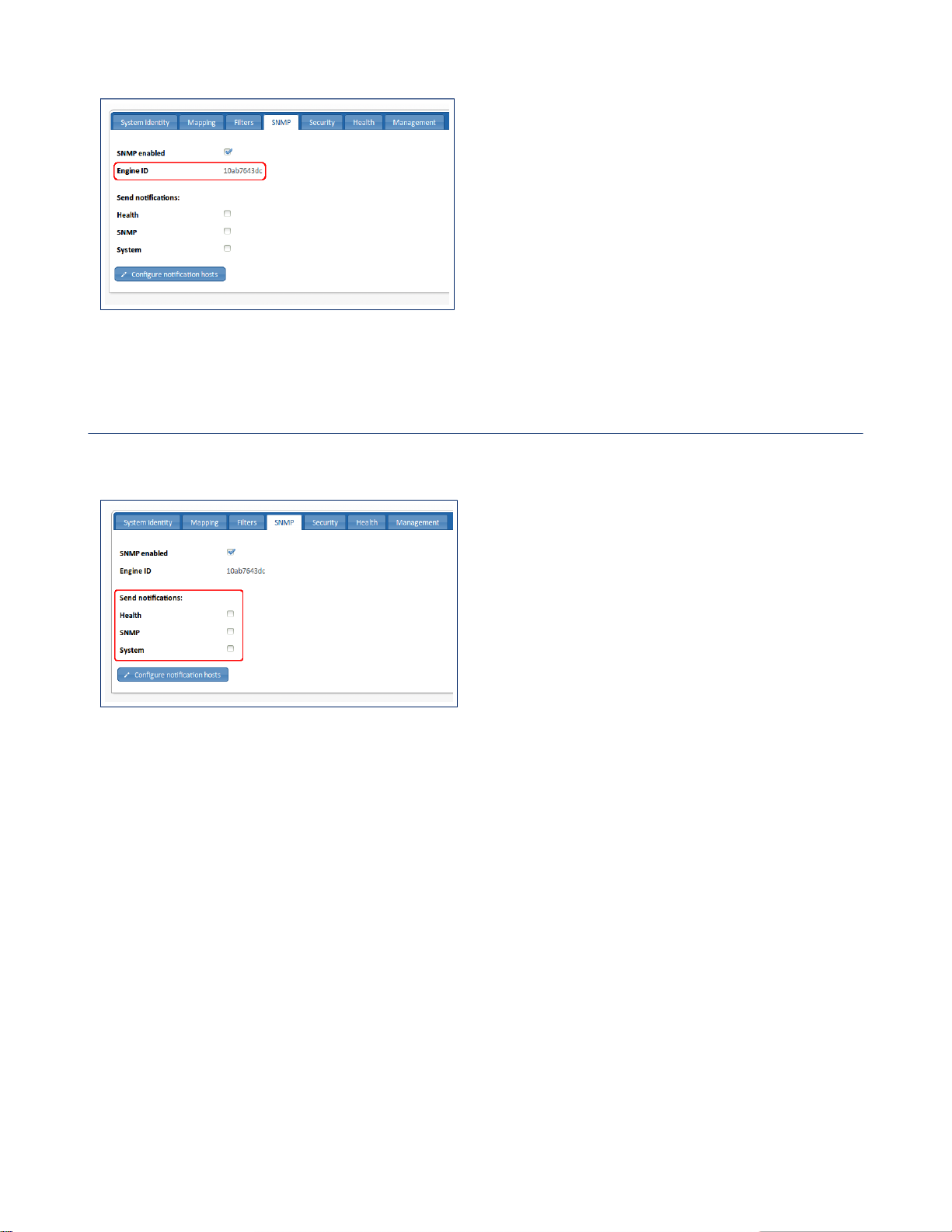
78 | SNMP | SmartNA-X 1G/10G Modular
Figure 64: The SNMP Local Engine ID
Defining notification (trap) settings
The Send notifications checkboxes allow you specify which SNMP notifications to send from this device. The recipients
of the SNMP notifications can be configured in the SNMP Notification Hosts dialog (see the figure below).
Figure 65: The SNMP Send notifications options (highlighted)
Specifying send notifications
1.
Click on the chassis and select the SNMP tab.
2.
Using the Send notifications options, select the notifications you want to send to your notification hosts from this
device. The following notifications are available:
• Health—the following events will trigger a Health notification:
• System temperature above threshold (nctapNotifySysTemperature)
• TAP module temperature above threshold (nctapNotifyTemperature)
• Power on/off (nctapNotifyPower)
• Fan on/off (nctapNotifyFan)
• SNMP—the following events will trigger an SNMP notification:
• System cold boot (coldStart)
• System restarted (warmStart)
• SNMP authentication failure (authenticationFailure)
• System—the following events will trigger a System notification:
• Port link-up state (linkUp)
SmartNA-X™ 1G/10G User Guide 1.4 © 2015 Network Critical Solutions Limited
Page 79

SmartNA-X 1G/10G Modular | SNMP | 79
• Port link-down state (linkDown)
• Data rate above high threshold (nctapNotifyXSTrafficOver)
• Data rate below low threshold (nctapNotifyXSTrafficUnder
• TAP module inserted or removed (nctapNotifyCard)
• Failed login attempt (ncUnauthorisedAccess)
3.
Click Review/apply and review pending changes. To apply these changes to the system, click Apply changes or click
'X' to cancel.
Configuring notification hosts
1.
Click on the chassis and select the SNMP tab.
2.
Click Configure notification hosts.
3.
To add a new host, click Add new notification host, or to edit an existing host click the icon that is next to the
required host. The Add/Edit notification host dialog displays (see the figure below).
4.
Enter or edit details for the notification host:
• Destination – Enter a location for the notification host in the following format: {protocol}:]{host}[:{port}] where
protocol can be udp or udp6; host can be a hostname or an IPv4 or IPv6 address; port is the UDP port on the host
• SNMP version – Choose whether notifications are to be sent using SNMP v1, v2c or v3.
• Notification type – Specify whether notifications may be sent as traps or (where supported) informs.
• Credentials – Enter security credentials for the Manager. For SNMP v1 or v2c it is the community string. For
SNMP v3 it is an existing local user (for traps) or remote user (for informs).
• Engine ID – Specify the corresponding engine ID where a remote user is specified
5.
Click Add host to finish setting up the notification host.
6.
Click Review/apply and review pending changes. To apply these changes to the system, click Apply changes or click
'X' to cancel.
Figure 66: The SNMP Add/Edit notification host dialog
Defining SNMPv1/v2 communities
Access rights in SNMPv1 and SNMPv2 are managed by defining communities in the Configure communities dialog,
which is available after clicking Traditional access control. The community name is a type of shared password between
the SNMP management station and the device. It is used to authenticate the SNMP management station.
Communities are only defined in SNMPv1 and v2 because SNMP v3 works with users instead of communities. The users
belong to groups that have access rights assigned to them.
SmartNA-X™ 1G/10G User Guide 1.4 © 2015 Network Critical Solutions Limited
Page 80
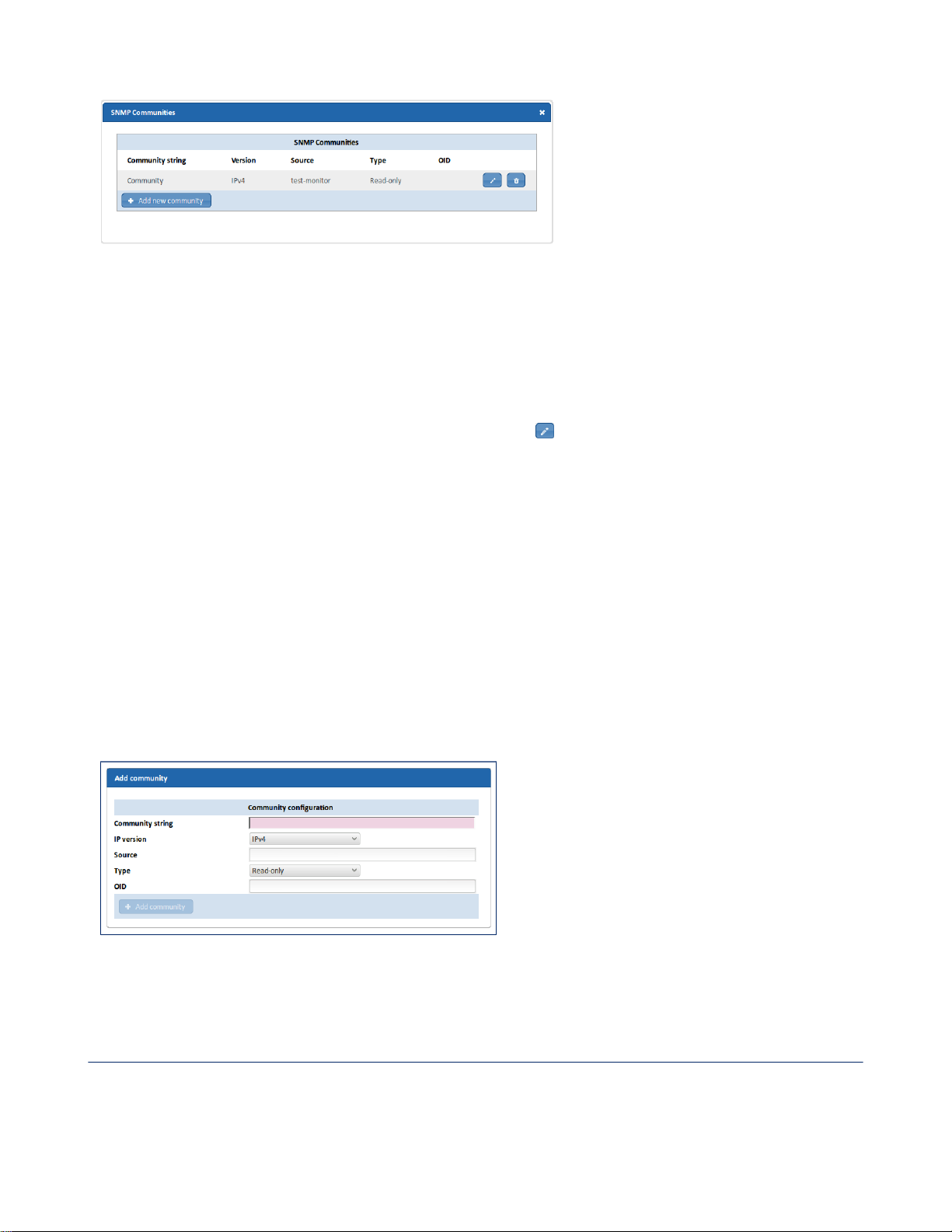
80 | SNMP | SmartNA-X 1G/10G Modular
Figure 67: The SNMP Communities dialog for SNMP v1 and v2
Define SNMPv1/v2 communities
1.
Click on the chassis and select the SNMP tab.
2.
In the Traditional access control area, click Configure communities. The SNMP Communities dialog displays.
3.
To define a new community, click Add new community, or click to edit an existing community. The Add/Edit
Community dialog displays (see the figure below).
4.
Enter or edit details for the community:
• Community string—Enter a secret/password string for the community to authenticate clients. The community
string is case-sensitive and must contain 1–32 alphanumeric characters (no spaces), and the first character must be
a letter.
• IP version—Specify whether this community allows access via IPv4 or IPv6.
• Source—You may restrict access to the community from certain sources, by specifying the source address, subnet
or hostname.
• Type—Specify whether this community allows read-only or read-write access to clients.
• OID—You may restrict access to the community to part of the MIB tree by specifying the OID.
5.
Click Add community to finish setting up the community.
6.
Click Review/apply and review pending changes. To apply these changes to the system, click Apply changes or click
'X' to cancel.
Figure 68: The Add community dialog for SNMP v1 and v2
Configuring SNMP v3
The recommended steps for configuring access to management information for SNMP v3 users are as follows:
1.
Define the users and their access models.
2.
Map any SNMP v1 communities to a security name.
SmartNA-X™ 1G/10G User Guide 1.4 © 2015 Network Critical Solutions Limited
Page 81
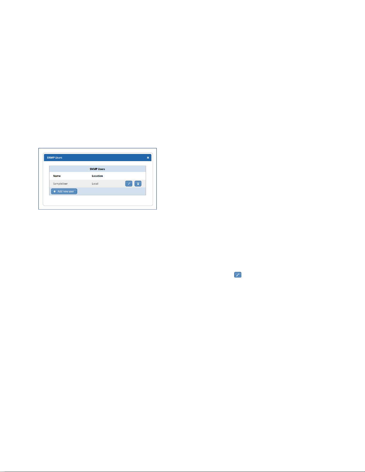
SmartNA-X 1G/10G Modular | SNMP | 81
3.
Create groups.
4.
Define the views that the group will be restricted to.
5.
Define an access policy for the group.
Defining SNMP users
An SNMP user is defined by the login credentials (username, passwords, and authentication method), and by the context
and scope in which it operates by association with a group and an Engine ID.
After a user is authenticated, it takes on the attributes of its group, and can then see or not see the views associated with
this group. Groups enable network managers to assign access rights to specific features, or feature aspects, to an entire
group of users instead of to a single user. A user can only be a member of a single group.
The SNMP Users dialog (shown below) enables the creation of SNMPv3 users. An SNMPv3 user is the combination of
a user along with a method that is used to authenticate the user and a password. SNMP user login credentials are verified
using the local database.
Figure 69: The SNMP Users dialog
Define an SNMP user
1.
Click on the chassis and select the SNMP tab.
2.
Under View-based access control, click Configure users. The SNMP Users dialog displays.
3.
To define a new user, click Add new user, or to edit an existing user click the icon for that user. The Add/Edit
new user dialog displays (see the figure below).
4.
Enter or edit details for the user:
• User name—Specify a name for the user. Names consist of 1–32 alphanumeric characters, and must begin with a
letter.
• Engine—Choose whether the user is a local user (most cases) or a remote user. If it is a remote user, you must also
specify the corresponding remote Engine ID. An Engine ID consists of 10–64 hex digits.
• Authentication—Specify whether authentication is to be used, and if so whether to use MD5 or SHA (more
secure). If authentication is in use, you must also specify a passphrase, which consists of 8–64 ASCII non-control
characters. If editing an existing user, you may leave this field blank if you wish to keep the existing passphrase.
• Privacy— Specify whether encryption is to be used, and if so whether to use DES or AES (more secure). If
encryption is in use, you must also specify a passphrase, which consists of 8–64 ASCII non-control characters. If
editing an existing user, you may leave this field blank if you wish to keep the existing passphrase.
5.
Click Add user to finish setting up the user.
6.
Click Review/apply and review pending changes. To apply these changes to the system, click Apply changes or click
'X' to cancel.
SmartNA-X™ 1G/10G User Guide 1.4 © 2015 Network Critical Solutions Limited
Page 82
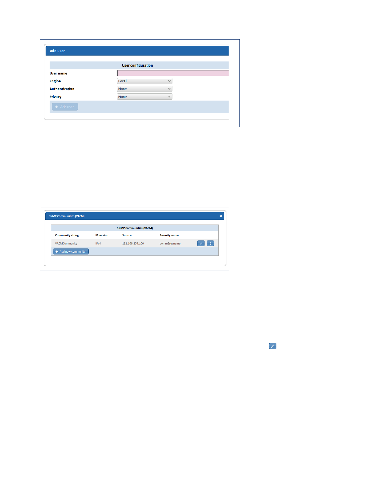
82 | SNMP | SmartNA-X 1G/10G Modular
Figure 70: The SNMP Add user dialog
Mapping SNMPv1/v2 users to SecurityNames
Clients that connect using SNMPv1/v2 must be mapped onto a “security name” and added to a group, the same as
SNMPv3 users.
The SNMP Communities (VACM) dialog, shown below, enables the mapping of a community string and a source IP or
network address to a security name (user name).
Figure 71: The SNMP Communities (VACM) dialog
Map SNMP v1 or v2 users to SecurityNames
1.
Click on the chassis and select the SNMP tab.
2.
Under View-based access control, click Configure communities. The SNMP Communities (VACM) dialog
displays.
3.
To map a new user, click Add new community, or to edit an existing mapping click the icon for that user. The
Add/Edit Community dialog displays (see the figure below).
4.
Enter or edit details for the community mapping:
• Community string—Specify the community string. The community string is case-sensitive and must contain 1–32
alphanumeric characters (no spaces), and the first character must be a letter.
• IP version—Specify whether this community allows access via IPv4 or IPv6.
• Source—You may restrict access to the community from certain sources, by specifying the source address, subnet
or hostname.
• Security name—Specify a security name (user name). The security name can be used later to add the user to a
group, like SNMPv3.
5.
Click Add community to finish setting up the community mapping.
SmartNA-X™ 1G/10G User Guide 1.4 © 2015 Network Critical Solutions Limited
Page 83
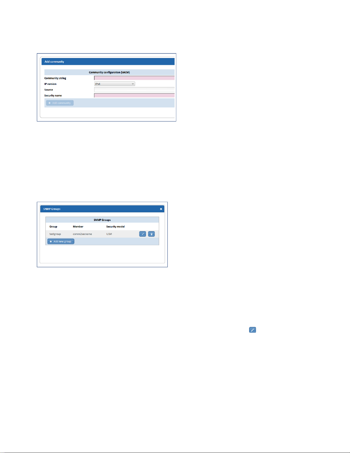
SmartNA-X 1G/10G Modular | SNMP | 83
6.
Click Review/apply and review pending changes. To apply these changes to the system, click Apply changes or click
'X' to cancel.
Figure 72: The SNMP Add community dialog for VACM
Creating SNMP groups
SNMPv3 provides for a way to control which events authorized and authenticated users can see and perform by
associating each user with a group. A group is a label for a logical entity (combination of attributes). A group is
operational only when it is associated with an SNMP user or an SNMP community. A group also has an attribute that tells
if members should have read, write, and/or notify privileges for the view.
From the web UI, groups are configured using the SNMP Groups dialog, shown below.
Figure 73: The SNMP Groups dialog
Create an SNMP group
1.
Click on the chassis and select the SNMP tab.
2.
Under View-based access control, click Configure groups. The SNMP Groups dialog displays.
3.
To define a new group, click Add new group, or to edit an existing community click the icon for that group. The
Add/Edit group member dialog displays (see the figure below).
4.
Enter or edit details for the group:
• Group name – Enter a name for the group. Names must start with a letter and cannot be more than 32
alphanumeric characters long.
• Member – Member to add to the group (only one user can be added at a time). The member may be an existing
local SNMP user or a security name assigned to an existing VACM-enabled SNMP community. The same member
may belong to different groups with different security models. The membership will apply only when the specified
security model is used for a request.
• Security model– Enter a security model for the group: SNMPv1, SNMPv2c, or SNMPv3 USM.
5.
Click Add group to finish setting up the group.
SmartNA-X™ 1G/10G User Guide 1.4 © 2015 Network Critical Solutions Limited
Page 84
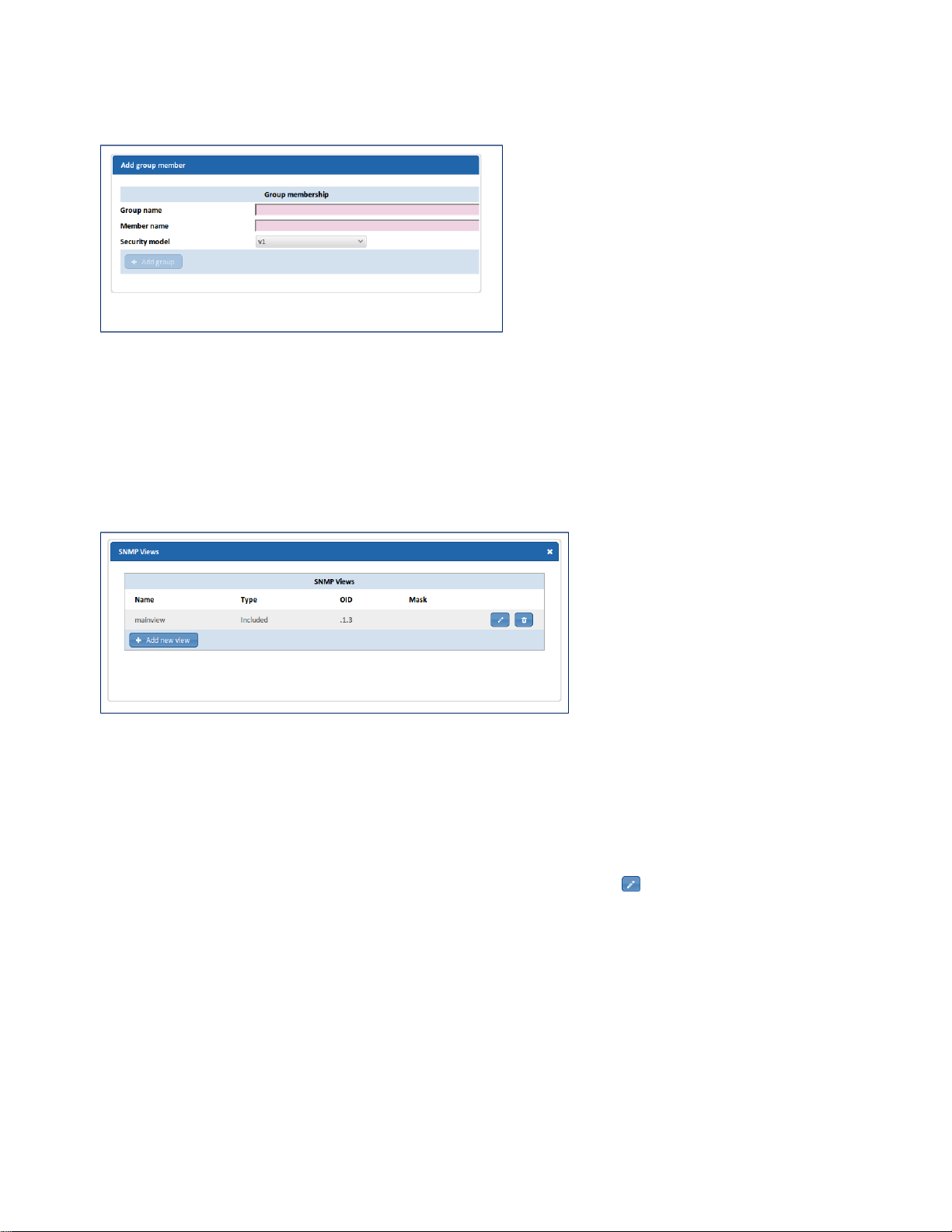
84 | SNMP | SmartNA-X 1G/10G Modular
6.
Click Review/apply and review pending changes. To apply these changes to the system, click Apply changes or click
'X' to cancel.
Figure 74: The SNMP Add/Edit group member dialog
Defining SNMP views
A view is a user-defined label for a collection of MIB tree subtrees. Each subtree ID is defined by the Object ID (OID)
of the root of the relevant subtrees. In extreme cases, this subtree can be a leaf, only. Each subtree is either included or
excluded in the view being defined.
Views are configured using the SNMP Views dialog, shown below.
Figure 75: The SNMP Views dialog
Define an SNMP view
1.
Click on the chassis and select the SNMP tab.
2.
Under View-based access control, click Configure views. The SNMP Views dialog displays.
3.
To define a new view, click Add new view, or to edit an existing view click the icon for that view. The Add/Edit
view member dialog displays (see the figure below).
4.
Click Add new view. The Add view member window appears.
5.
Enter or edit details for the view:
• Name – Specify a name for the view. Names consist of 1–32 alphanumeric characters, and must begin with a letter.
• View type– Specify whether the view contains the tree below the specified OID or everything else.
• OID – Specify the position in the management tree below which this view applies.
• Mask – Can be used to specify that only some of the sub-identifiers in the OID are to be matched. The mask can be
used to define a view covering a particular row (or rows) in a table, by matching against the appropriate table index
value but skipping the column sub-identifier.
6.
Click Add view to finish setting up the view.
SmartNA-X™ 1G/10G User Guide 1.4 © 2015 Network Critical Solutions Limited
Page 85
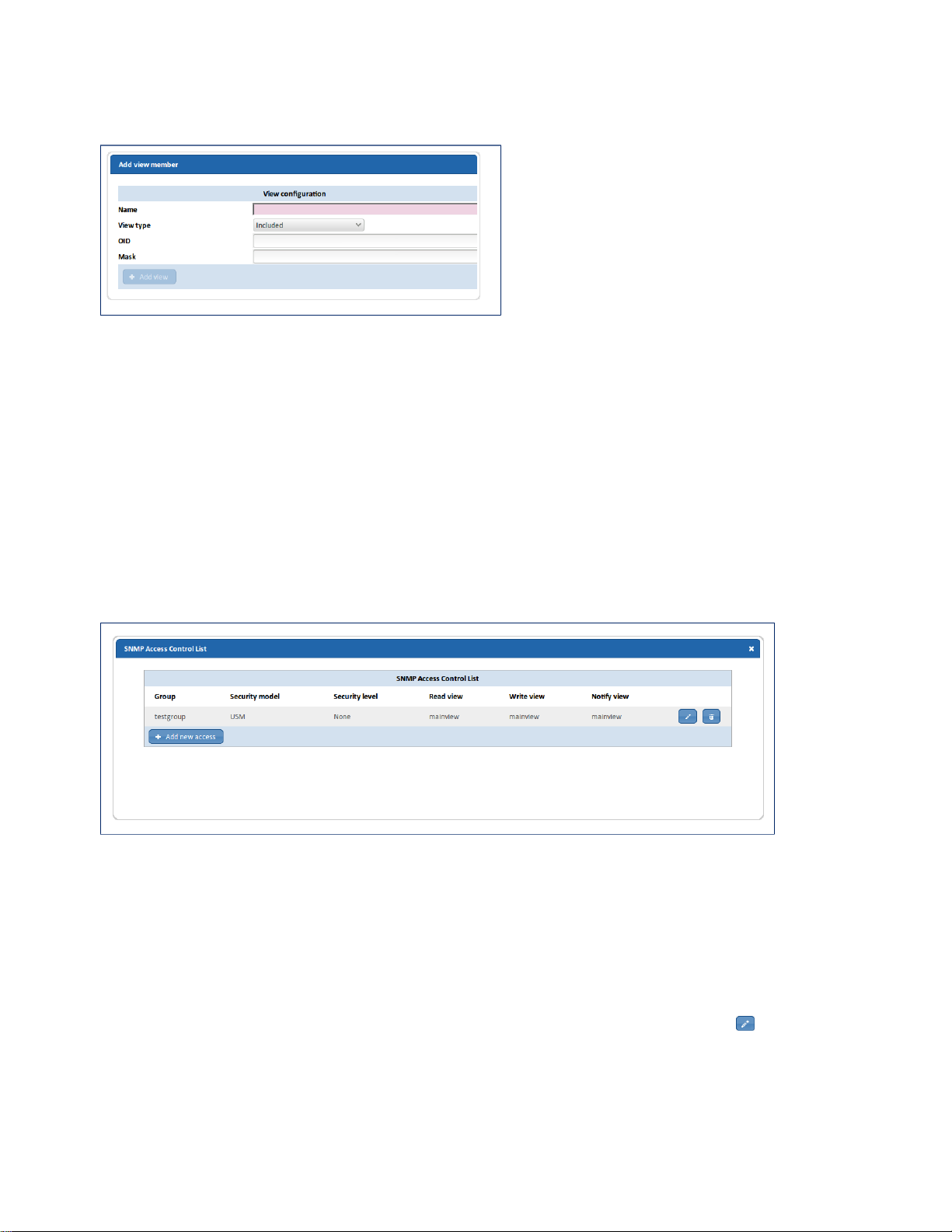
SmartNA-X 1G/10G Modular | SNMP | 85
7.
Click Review/apply and review pending changes. To apply these changes to the system, click Apply changes or click
'X' to cancel.
Figure 76: The SNMP Add/Edit view member dialog
Defining the group access policy
The group access policy defines the access rights per group and the minimum security model and security level required to
access the group. The access options are:
• Read—Management access is read-only for the selected view. Otherwise, a user or a community associated with this
group, is able to read all MIBs except those that control SNMP itself.
• Write—Management access is write for the selected view. Otherwise, a user or a community associated with this
group, is able to write all MIBs except those that control SNMP itself.
• Notify—Sends only notifications with contents that is included in the SNMP view selected for notification. Otherwise,
there is no restriction on the contents of the notifications.
Group access policies are configured using the SNMP Access Control List dialog, shown below.
Figure 77: The SNMP Access Control List dialog
Define a group access policy
1.
Click on the chassis and select the SNMP tab.
2.
Under View-based access control, click Configure access control list. The SNMP Access Control Listdialog
displays.
3.
To define a new access policy, click Add new access, or to edit an existing access policy click the icon. The Add/
Edit access dialog displays (see the figure below).
4.
Enter details for the group access policy:
• Group name—Specify the name of an existing group that will receive this access.
SmartNA-X™ 1G/10G User Guide 1.4 © 2015 Network Critical Solutions Limited
Page 86
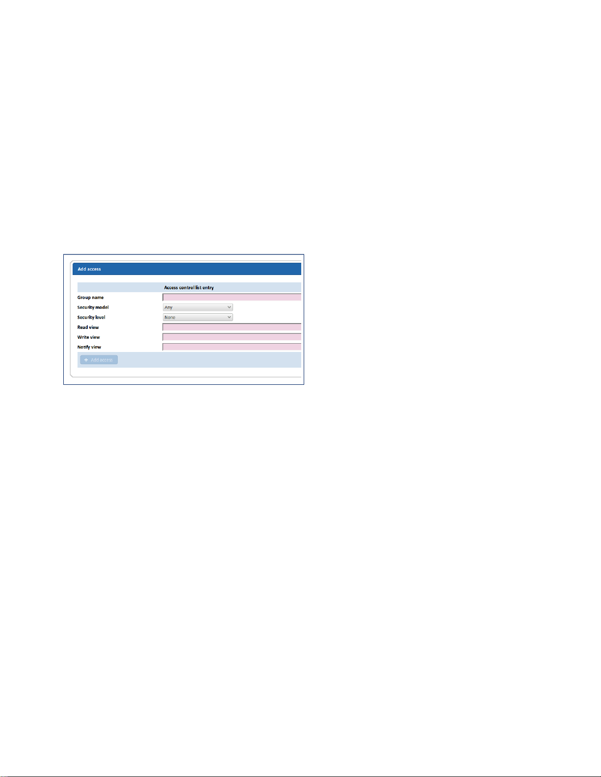
86 | SNMP | SmartNA-X 1G/10G Modular
• Security model—Specify the security model for the view, either any security model, SNMPv1, SNMPv2c,
SNMPv3 USM. Access will only be granted if the security model matches the request.
• Security level—Specify the security level for the view. Access will only be granted if the security of the request
meets the minimum requirement specified here. The order is: None (lowest), Authentication only, Authentication +
Privacy (highest).
• Read view—Specify the names of existing views to which get requests will be mapped. If no access is required,
create a ‘None’ view with no access to any MIB and specify it here.
• Write view—Specify the names of existing views to which set requests will be mapped. If no access is required,
create a ‘None’ view with no access to any MIB and specify it here.
• Notify view—Specify the names of existing views to which notify requests will be mapped. If no access is
required, create a ‘None’ view with no access to any MIB and specify it here.
5.
Click Add view to finish setting up the group access policy.
6.
Click Review/apply and review pending changes. To apply these changes to the system, click Apply changes or click
'X' to cancel.
Figure 78: The SNMP Add access dialog
SmartNA-X™ 1G/10G User Guide 1.4 © 2015 Network Critical Solutions Limited
Page 87

Chapter 11
Command Line Reference
CLI notation
This manual uses standard command-line notation for SmartNA-X CLI commands.
Format Description
Command Command keywords (not case-sensitive).
Variable Placeholder for which you must supply a value. If more than one variable can be
entered, angled brackets “< >” are used to differentiate placeholders.
{required-items} Set of required items. Choose one from the list to complete the command.
[optional-items] Optional items. Separated by ‘|’ where there are several items to choose from (choose
one item from the list).
CLI editing and command completion
The CLI uses standard keyboard controls for auto-completion of commands and line editing.
• Typing cursor L/R moves the cursor through a partially typed command
• Typing cursor U/D moves back and forth through previously typed commands
• Delete / backspace have their expected editing effects.
• Typing TAB key part-way through a word causes the word to be completed, if unambiguous.
• Typing TAB twice lists all the alternatives
SmartNA-X™ 1G/10G User Guide 1.4 © 2015 Network Critical Solutions Limited
Page 88

88 | Command Line Reference | SmartNA-X 1G/10G Modular
General CLI commands
This section provides reference information for general CLI commands.
Help
Use the help command to display help for the command interpreter (CLI), and usage information for authorization,
network, filter, map, port, SNMP, and Load Balancing commands.
Syntax
help
help { set | show | auth | net | filter | map | port | snmp | loadbalancing | customfields | vline }
Parameters
• set Display help for set commands
• show Display help for show commands
• auth Display help for authorization and authentication commands.
• net Display help for network commands.
• filter Display help for packet filtering commands.
• map Display help for port mapping commands.
• port Display help for port communications commands.
• snmp Display help for SNMP commands.
• loadbalancing Display help for Load Balancing commands
• customfields Display help for custom field (user-defined bytes) commands
• vline Display help for V-Line module commands.
Examples
• Display CLI help:
CONTROLLER>help
The command interpreter supports the following basic commands:
Help
Select
Set
Show
Reset
Create
Delete
Clear
Commit
Reboot
Exit
Quit
The general form of a command is a series of words or numbers separated
by whitespace. All commands are case-insensitive.
'select controller' or 'select slot N' selects a current home location.
This will select either the controller or another card in the system. Other
commands may implicitly use the current location, for example in
deciding which port a 'show port' command refers to.
'set' allows you to write system parameters.
'show' allows you to read system parameters.
SmartNA-X™ 1G/10G User Guide 1.4 © 2015 Network Critical Solutions Limited
Page 89

SmartNA-X 1G/10G Modular | Command Line Reference | 89
'create settings <name>' allows you to save the current configuration to
permanent memory under the specified name.
'restore <name>' discards any parameter changes you may have made and reverts
to the settings previously saved as <name>.
'delete settings <name> permanently removes a previously saved set of settings.
'clear counters' clears the traffic counters on the currently selected card.
'clear maps' removes all maps, filters and load balancing policy (lbheaders) settings.
'commit' programs the device with the maps, filters, load balancing policy and vline
settings defined with 'set map', 'set filter', 'set lbheaders' and 'set vline'
commands.
'reboot' reboots the current card or controller.
'exit' or 'quit' exit this program.
more detailed help is obtained by:
'help set' or 'help show'
'help port'
'help map'
'help filter'
'help net'
'help auth'
'help snmp'
'help vline'
'help loadbalancing'
'help customfields'
• Display command usage for network commands:
CONTROLLER>help net
The following commands control and display networking parameters
The commands to set gateway and dns cannot be used in DHCP mode.
show IPv4 : show all IPv4 settings
show IPv6 : show all IPv6 settings
set IPv4 static <IPv4 address> <IPv4 mask> [gateway <IPv4 address>]:
set IPv4 address, network mask and optionally gateway
set IPv4 dhcp : use DHCP for address, netmask, gateway and dns.
set IPv4 gateway <IPv4 address> : set IPv4 gateway
set IPv4 dns <IPv4 address> : set IPv4 domain name system server
set IPv6 static <IPv6 address> <prefix value 16 - 124> [gateway <IPv6 gateway>]:
set IPv6 address, prefix length and optionally gateway
set IPv6 gateway <IPv6 address> : set IPv6 gateway
commit
Use the commit command to replace the live settings on the device with your new configuration after making changes to
port mappings, packet filters, V-Line modules, and Load Balancer groups. Until you commit your changes they remain
pending in dynamic memory only and will be lost if you log out or if the system is restarted.
Syntax
commit
Parameters
This command has no arguments or keywords.
Example
CONTROLLER>commit
Committing maps
Committing filters
Committing load balance policy headers
SmartNA-X™ 1G/10G User Guide 1.4 © 2015 Network Critical Solutions Limited
Page 90

90 | Command Line Reference | SmartNA-X 1G/10G Modular
create settings
Use the create settings command to save the current configuration to permanent memory. The configuration includes port
settings, port mappings, any filters that have been defined, and the current SNMP configuration.
Syntax
create settings config-name
Parameters
config-name Specify a name for the configuration. The name may contain letters, numbers and the underscore ‘_’
character. Spaces are not allowed.
Example
Save the current configuration as breakout_10G
CONTROLLER>create settings breakout_10G
Settings saved OK
restore
Use the restore command to restore a saved configuration, overwriting the current configuration in the process. Entering
restore without a configuration name produces a list of all available configurations.
Syntax
restore
restore config-name
Parameters
config-name Specify the name of the configuration to restore.
Example
List the available configurations then restore breakout_10G:
CONTROLLER>restore
restore: Need name for settings to restore
The following sets of settings are available :
v_line_egress
full_traffic
breakout_10G
aggregate_1G
replicate_1G
with2extramaps
factory_defaults
CONTROLLER>restore breakout_10G
applied settings OK
delete settings
Use the delete settings command to delete a saved configuration. You may use the restore command to list the available
configurations.
Syntax
delete settings config-name
Parameters
config-name Specify the configuration name to delete.
SmartNA-X™ 1G/10G User Guide 1.4 © 2015 Network Critical Solutions Limited
Page 91

SmartNA-X 1G/10G Modular | Command Line Reference | 91
Example
List the available configurations then delete breakout_10G:
CONTROLLER>restore
restore: Need name for settings to restore
The following sets of settings are available :
v_line_egress
full_traffic
breakout_10G
aggregate_1G
replicate_1G
with2extramaps
factory_defaults
CONTROLLER>delete settings breakout_10G
deleted OK
reboot
Use the reboot command to restart the SmartNA-X system Controller, or the currently selected module in the CLI. The
system takes around two minutes to restart, during which time access to the management interfaces will not be available.
Copper ports which have LFP or LMP enabled will continue to pass traffic, but all other ports will stop passing traffic
while the system reboots.
Syntax
reboot
Parameters
This command has no arguments or keywords.
Example
Reboot the system:
CONTROLLER>reboot
Rebooted card 2
Rebooted card 3
Rebooted card 4
Trap Request queue started for writing(32769)
Rebooted motherboard
CONTROLLER>
Broadcast message from [email protected] (Fri Apr 4 09:19:48 2014):
The system is going down for reboot NOW!
Connection to 192.168.0.122 closed by remote host.
Connection to 192.168.0.122 closed.
[email protected]:~#
set timeout
Use the set timeout command to specify a timeout value, in minutes, for command line sessions (it does not affect web
sessions). You may disable timeouts by setting 0 as the timeout value. Use show system to view the current timeout
setting.
Syntax
set timeout mins
SmartNA-X™ 1G/10G User Guide 1.4 © 2015 Network Critical Solutions Limited
Page 92

92 | Command Line Reference | SmartNA-X 1G/10G Modular
Parameters
mins Specify a timeout, in minutes, for CLI sessions. Valid range 1–1440 (1 minute to 24 hours). Default value 15
minutes. Use 0 to disable session timeouts.
Example
Set the CLI session timeout to 30 minutes:
CONTROLLER>set timeout 30
CONTROLLER>show system
Device Name: Network Critical
Device Contact:
Device Location:
MAC address: 00:1d:ff:21:92:c5
IPv4 Addressing Mode : static
IPv4 Address: 192.168.0.123
IPv4 Netmask: 255.255.255.0
IPv4 Gateway: 192.168.0.3
IPv4 DNS Server: None configured
Stored IPv6 Global Address : ::
Stored IPv6 Prefix Length : 0
Stored IPV6 Gateway : ::
IPv6 Link Local Address : fe80::21d:ffff:fe21:92c5
Active IPv6 Global Address : ::
Active IPv6 Prefix Length : 0
Active IPv6 Gateway : ::
SNMP: on
Chassis Type: 1U
Power Supply 1: DOWN
Power Supply 2: UP
Time and Date: 11:23:20 Fri 21 Mar 2014
System Timeout: 30 minutes
exit
Use the exit command to stop the current CLI session and return to the host operating system. Any pending changes will
be lost if they are not committed before exiting. Any updates made to the network interface settings will be implemented
upon exiting the CLI.
Syntax
exit
Parameters
This command has no arguments or keywords.
Example
CONTROLLER>exit
Exiting CLI
Connection to 192.168.0.122 closed.
[email protected]:~#
SmartNA-X™ 1G/10G User Guide 1.4 © 2015 Network Critical Solutions Limited
Page 93

SmartNA-X 1G/10G Modular | Command Line Reference | 93
System name, contact and location
This section provides reference information for system name, contact and location commands.
show system
Use the show system command display information about the system, including device name, contact and location
information, MAC, network interface addresses (IPv4 and IPv6), chassis up time and PSU status. Details are also provided
for the modules that are present in the chassis slots.
Syntax
show system
Parameters
This command has no arguments or keywords.
Example
CONTROLLER>show system
Device Name: Network Critical
Device Contact:
Device Location:
MAC address: 00:1e:ff:63:42:89
IPv4 Addressing Mode : static
IPv4 Address: 192.168.0.126
IPv4 Netmask: 255.255.255.0
IPv4 Gateway: 192.168.0.254
IPv4 DNS Server: None configured
Stored IPv6 Global Address : ::
Stored IPv6 Prefix Length : 0
Stored IPV6 Gateway : ::
IPv6 Link Local Address : fe80::25d:ffaf:fe86:4399
Active IPv6 Global Address : ::
Active IPv6 Prefix Length : 0
Active IPv6 Gateway : ::
SNMP: on
Chassis Type: 1U
Power Supply 1: UP
Power Supply 2: DOWN
Time and Date: 18:58:53 Sun 22 Feb 2015
System Timeout: 15 minutes
Slot 0: 5502 MODULE_SFPPLUS_SFP
Slot 1: MODULE_ABSENT
Slot 2: MODULE_ABSENT
Slot 3: MODULE_ABSENT
Slot 4: MODULE_ABSENT
CONTROLLER>
show name
Use the show name command to report the system name details.
Syntax
show name
SmartNA-X™ 1G/10G User Guide 1.4 © 2015 Network Critical Solutions Limited
Page 94

94 | Command Line Reference | SmartNA-X 1G/10G Modular
Parameters
This command has no arguments or keywords.
Example
Report the system name:
CONTROLLER>show name
NC-unit14 copper SFP+ mixed
set name
Use the set name command to enter a system name for the device installation.
Syntax
set name name-info
Parameters
name-info Specify a name for the system using 1-19 alphanumeric characters. Commas and other punctuation characters
may be used but may be replaced on RADIUS servers by underscores "_".
Example
Set name information to "Network Critical SmartNA-X":
CONTROLLER>set name Network Critical SmartNA-X
CONTROLLER>show name
Network Critical SmartNA-X
show location
Use the show location command to report location details (blank by default).
Syntax
show location
Parameters
This command has no arguments or keywords.
Example
Report location details:
CONTROLLER>show location
boston_data-center rack32D
set location
Use the set location command to enter location information for the device installation.
Syntax
set location location-info
Parameters
location-info Specify location details using 1-19 alphanumeric characters. Commas and other punctuation characters may
be used but may be replaced on RADIUS servers by underscores "_".
SmartNA-X™ 1G/10G User Guide 1.4 © 2015 Network Critical Solutions Limited
Page 95

Example
Set location information to “Secure rack A”:
CONTROLLER>set location Secure rack A
CONTROLLER>show location
Secure rack A
show contact
Use the show contact command to report contact details (blank by default).
Syntax
show contact
Parameters
This command has no arguments or keywords.
Example
Report contact details:
SmartNA-X 1G/10G Modular | Command Line Reference | 95
CONTROLLER>show contact
[email protected] 555-0123 xt. 4
set contact
Use the set contact command to enter contact information for the device installation.
Syntax
set contact contact -details
Parameters
contact details Specify contact details using 1-19 alphanumeric characters. Commas and other punctuation characters
may be used but may be replaced on RADIUS servers by underscores "_".
Example
Set contact information to "Network admin Tel: 4321":
CONTROLLER>set contact Network admin Tel: 4321
CONTROLLER>show contact
Network admin Tel: 4321
set banner
Use the set banner command to specify a banner message. The message can be up to 25 lines long and may be used to
provide useful information about this device to anyone querying the banner message.
Syntax
set banner line-number text
Parameters
line-number Specify a line number for the message. Valid range 1–25.
text Specify the text for the banner. It is not necessary to enclose the message in quotes ("..."). The text will be added to
the specified line number.
SmartNA-X™ 1G/10G User Guide 1.4 © 2015 Network Critical Solutions Limited
Page 96

96 | Command Line Reference | SmartNA-X 1G/10G Modular
Example
CONTROLLER>set banner 1 This SmartNA-X device is
CONTROLLER>set banner 2 filtering for HTTP/S packets entering VLAN 23 on the
CONTROLLER>set banner 3 main data network.
show banner
Use the show banner command to display the current banner message.
Syntax
show banner
Parameters
This command has no arguments or keywords.
Example
Report the system name:
CONTROLLER>show banner
Banner message line 1
Banner message line 2
Banner message line 3
SmartNA-X™ 1G/10G User Guide 1.4 © 2015 Network Critical Solutions Limited
Page 97

SmartNA-X 1G/10G Modular | Command Line Reference | 97
Network configuration commands
This section provides reference information for network configuration commands.
show ntp
Use the show ntp command to display the NTP time-server address.
Syntax
show ntp
Parameters
This command has no arguments or keywords.
Example
Display the NTP server address:
CONTROLLER>show ntp
NTP server : 192.168.254.21
create ntp
Use the create ntp command add an NTP time-server. After adding an NTP server, the system will attempt to synchronize
the internal clock with the NTP server.
Syntax
create ntp address
Parameters
address Specify the IPv4 address of the NTP server.
Example
Specify an NTP server with address 192.168.0.10:
CONTROLLER>create ntp 192.168.0.10
delete ntp
Use the delete ntp command to delete NTP settings.
Syntax
delete ntp
Parameters
This command has no arguments or keywords.
Example
Delete NTP settings:
CONTROLLER>delete ntp
SmartNA-X™ 1G/10G User Guide 1.4 © 2015 Network Critical Solutions Limited
Page 98

98 | Command Line Reference | SmartNA-X 1G/10G Modular
show ipv4
Use the show ipv4 command to show the current network interface IPv4 settings, including mode (static or dynamic),
IPv4 address, IPv4 gateway, netmask, and any configured DNS server.
Syntax
show ipv4
Parameters
This command has no arguments or keywords.
Example
Report IPv4 address:
CONTROLLER>show ipv4
IPv4 Addressing Mode : static
IPv4 Address: 192.168.0.122
IPv4 Netmask: 255.255.255.0
IPv4 Gateway: 192.168.0.254
IPv4 DNS Server: None configured
set ipv4 static
Use the set IPv4 static command to define static IPv4 network settings. Changes to network interface settings are
implemented after exiting the CLI, or immediately if connecting over IPv6 or via the Console port.
Syntax
set ipv4 static ipv4-address netmask [ gateway gateway-address ]
Parameters
• ipv4-address Specify the network interface IPv4 address in dotted-decimal format (a.b.c.d).
• netmask Specify a subnet mask (netmask).
• gateway gateway-address (Optional) Specify a gateway address.
Example
Define the following static IPv4 network settings, and then exit the CLI to implement:
• Network Address: 192.168.0.122
• Netmask: 255.255.255.0
• Gateway address: 192.168.0.1
CONTROLLER>set ipv4 static 192.168.0.122 255.255.255.0 gateway 192.168.0.1
Network settings will take effect when you exit CLI.
exit to enable new network settings
CONTROLLER>exit
Exiting CLI
exit to enable new network settings
Applying new IPv4 network settings
Addressing Mode : static
Address: 192.168.0.122
Netmask: 255.255.255.0
Gateway: 192.168.0.254
Connection to 192.168.0.122 closed.
[email protected]:~$
set ipv4 gateway
Use the set ipv4 gateway command to define a gateway address for inter-network routing. Changes to network interface
settings are implemented after exiting the CLI, or immediately if connecting over IPv6 or via the Console port.
SmartNA-X™ 1G/10G User Guide 1.4 © 2015 Network Critical Solutions Limited
Page 99

SmartNA-X 1G/10G Modular | Command Line Reference | 99
Syntax
set ipv4 gateway ipv4-address
Parameters
ipv4-address Specify the IPv4 address of the gateway, in dotted-decimal format (a.b.c.d).
Example
Define IPv4 gateway 192.168.0.1, and then exit the CLI to implement:
CONTROLLER>set ipv4 gateway 192.168.0.1
Network settings will take effect when you exit CLI.
exit to enable new network settings
CONTROLLER>exit
Exiting CLI
exit to enable new network settings
Applying new IPv4 network settings
Addressing Mode : static
Address: 192.168.0.122
Netmask: 255.255.255.0
Gateway: 192.168.0.254
Connection to 192.168.0.122 closed.
[email protected]:~$
set ipv4 dns
Use the set ipv4 dns command to define an IPv4 address for an IP Domain Name System (DNS) server. Adding a DNS
server allows the use of server names at the command line. Changes to network interface settings are implemented after
exiting the CLI, or immediately if connecting over IPv6 or via the Console port.
Syntax
set ipv4 dns ipv4-address
Parameters
ipv4-address Specify the IPv4 address of the DNS server, in dotted-decimal format (a.b.c.d).
Example
Define DNS server 192.168.100.1, and then exit the CLI to implement:
CONTROLLER>set ipv4 dns 192.168.100.1
CONTROLLER>exit
Exiting CLI
Connection to 192.168.0.122 closed.
[email protected]:~$
set ipv4 dhcp
Use the set ipv4 dhcp command to acquire an IP address for the Ethernet interface from the Dynamic Host Configuration
Protocol (DHCP) server. DHCP client configuration implicitly removes the static IP address configuration on the
interface. Changes to network interface settings are implemented after exiting the CLI, or immediately if connecting over
IPv6 or via the Console port.
Syntax
set ipv4 dhcp
SmartNA-X™ 1G/10G User Guide 1.4 © 2015 Network Critical Solutions Limited
Page 100

100 | Command Line Reference | SmartNA-X 1G/10G Modular
Parameters
This command has no arguments or keywords.
Example
Configure the device to acquire an IP address from a DHCP server:
CONTROLLER>set ipv4 dhcp
CONTROLLER>exit
Exiting CLI
Connection to 192.168.0.122 closed.
[email protected]:~$
show ipv6
Use the show ipv6 command to show the current network interface IPv6 settings, including the global IPv6 address,
prefix length, IPv6 link-local address, and IPv6 gateway address.
Syntax
show ipv6
Parameters
This command has no arguments or keywords.
Example
Report network interface IPv6 address:
CONTROLLER>show ipv6
Set Global Address : 2001::5
Set Prefix Length : 16
Set Gateway : 2001::4
Link Local Address : fe80::21d:ffff:fe00:91ff
Active Global Address : 2001::5
Active Prefix Length : 16
Active Gateway : 2001::4
exit to enable new network settings
set ipv6 static
Use the set IPv6 static command to define static IPv6 network settings. The system carries an implicit fixed linklocal IPv6 address, but you can use this command to add one additional global IPv6 address. The new address will be
implemented after exiting from the CLI.
Syntax
set ipv6 static ipv6-address prefix-length [ gateway gateway-address ]
Parameters
• ipv6-address Specify the network interface global IPv6 address in standard IPv6 format (2001:db8::52:0:1).
• prefix-length Specify a subnet mask (netmask).
• gateway gateway-address (Optional) Specify an IPv6 gateway address.
Example
Define the following static IPv6 network settings, and then exit the CLI to implement:
• Interface address: 2001:db8::52:0:21
• Prefix length: 64-bits
• Gateway: 2001:db8::52:0:10
SmartNA-X™ 1G/10G User Guide 1.4 © 2015 Network Critical Solutions Limited
 Loading...