

Page 1
Netopia™ 4753
G.SHDSL Integrated Access Device
Administration Guide
Page 2

Copyright
©2001 Netopia, Inc., v.051601
All rights reserved. Printed in the U.S.A.
This manual and any associated artwork, software, and product designs are copyrighted with
all rights reserved. Under the copyright laws such materials may not be copied, in whole or
part, without the prior written consent of Netopia, Inc. Under the law, copying includes
translation to another language or format.
Netopia, Inc.
2470 Mariner Square Loop
Alameda, CA 94501-1010
U.S.A.
Part Number
For additional copies of this electronic manual, order Netopia par t number 6161091-PF-01.
Page 3

CCCCoooonnnntttteeeennnnttttss
ss
Contents iii
Part I: Getting Started
Chapter 1 — Introduction.......................................................... 1-1
Overview ....................................................................... 1-1
Features and Capabilities ............................................... 1-1
How to Use This Guide ................................................... 1-2
Chapter 2 — Setting Up Internet Services .................................2-1
Definition of Terms......................................................... 2-1
Finding an Internet Service Provider ................................ 2-2
Unique requirements............................................ 2-2
Pricing and support.............................................. 2-2
Endorsements ..................................................... 2-2
Deciding on an ISP Account ............................................ 2-2
Setting up a Netopia 4753 account....................... 2-3
Obtaining an IP address ....................................... 2-3
Obtaining Information from the ISP.................................. 2-3
Local LAN IP address information to obtain............ 2-3
G
Chapter 3 — Making the Physical Connections..........................3-1
Find a Location .............................................................. 3-1
What You Need .............................................................. 3-2
Important Safety instructions ......................................... 3-3
Identify the Connectors and Attach the Cables ................. 3-4
Netopia 4753 Status Lights............................................ 3-5
Chapter 4 — Sharing the Connection.........................................4-1
Configuring TCP/IP on Windows-based Computers............ 4-2
Dynamic configuration (recommended) .................. 4-2
Static configuration (optional) ............................... 4-3
Configuring TCP/IP on Macintosh Computers ................... 4-5
Dynamic configuration (recommended) .................. 4-5
Static configuration (optional) ............................... 4-6
Page 4

iv Administration Guide
Chapter 5 — Connecting to Your Local Network ......................... 5-1
Readying Computers on Your Local Network..................... 5-2
Connecting to an IP and Telephone Network..................... 5-3
Chapter 6 — Console-Based Management .................................6-1
Connecting through a Telnet Session............................... 6-2
Configuring Telnet software ................................... 6-2
Connecting a Console Cable to Your Device ..................... 6-3
Navigating through the Console Screens.......................... 6-5
Chapter 7 — Easy Setup ........................................................... 7-1
Easy Setup Console Screens .......................................... 7-1
Accessing the Easy Setup console screens............ 7-1
Quick Easy Setup Connection Path.................................. 7-3
DSL Line Configuration ......................................... 7-5
Voice Easy Setup ................................................. 7-6
Easy Setup Profile................................................ 7-7
IP Easy Setup ...................................................... 7-8
Easy Setup Security Configuration ......................... 7-9
Chapter 8 — Voice Configuration............................................... 8-1
Introduction................................................................... 8-1
Explanation of terms ............................................ 8-1
Configuring the Voice Features........................................ 8-2
Part II: Advanced Configuration
Chapter 9 — WAN and System Configuration .............................9-1
WAN Configuration ......................................................... 9-2
Multiple ATM Permanent Virtual Circuit Support ............... 9-3
Multiple ATM PVC overview ................................... 9-3
Multiple ATM PVC configuration............................. 9-4
Changing a circuit ................................................ 9-5
Adding a circuit.................................................... 9-7
Monitoring multiple virtual circuits......................... 9-8
Page 5

Contents v
Creating a New Connection Profile................................. 9-10
The WAN Default Profile................................................ 9-13
IP Parameters (Default Profile) screen ................. 9-14
The ATMP/PPTP Default Profile ..................................... 9-15
System Configuration Screens ..................................... 9-15
Navigating through the System Configuration
screens............................................................. 9-15
System Configuration Features ..................................... 9-16
Network protocols setup..................................... 9-17
Filter sets.......................................................... 9-17
IP address serving ............................................. 9-17
Date and time (Network Time Protocol)................ 9-17
Console configuration......................................... 9-19
SNMP (Simple Network Management Protocol)..... 9-20
Security............................................................. 9-20
Upgrade feature set ........................................... 9-20
Logging ............................................................. 9-20
Installing the Syslog client .................................. 9-21
G
Chapter 10 — IP Setup ........................................................... 10-1
IP Setup...................................................................... 10-2
IP subnets......................................................... 10-4
Static routes ..................................................... 10-6
IP Address Serving .................................................... 10-10
IP Address Pools.............................................. 10-13
DHCP NetBIOS Options .................................... 10-15
More Address Ser ving Options.................................... 10-17
Configuring the IP Address Server options ......... 10-18
DHCP Relay Agent...................................................... 10-23
Connection Profiles .................................................... 10-25
Chapter 11 — Multiple Network Address Translation ...............11-1
Overview ..................................................................... 11-1
Features ........................................................... 11-1
Page 6

vi Administration Guide
Supported traffic ............................................... 11-5
MultiNAT Configuration ................................................. 11-6
Easy Setup Profile configuration .......................... 11-6
Server Lists and Dynamic NAT configuration......... 11-6
IP setup ............................................................ 11-7
Modifying map lists.......................................... 11-13
Moving maps................................................... 11-15
Adding Server Lists.................................................... 11-17
Modifying server lists ....................................... 11-20
Deleting a server ............................................. 11-22
Binding Map Lists and Server Lists ............................. 11-23
IP profile parameters........................................ 11-23
IP Parameters (WAN Default Profile) .................. 11-25
NAT Associations....................................................... 11-27
MultiNAT Configuration Example.................................. 11-29
Chapter 12 — Virtual Private Networks (VPNs)........................ 12-1
Overview ..................................................................... 12-1
About PPTP Tunnels ..................................................... 12-3
PPTP configuration ............................................. 12-4
About IPsec Tunnels..................................................... 12-7
Configuration ..................................................... 12-7
IP Profile Parameters........................................ 12-10
Advanced IP Profile Options .............................. 12-11
Interoperation with other features ..................... 12-12
Encryption Support .......................................... 12-12
ATMP/PPTP Default Answer Profile .............................. 12-13
VPN QuickView .......................................................... 12-14
Dial-Up Networking for VPN ......................................... 12-15
Installing PPTP and Configuring Dial-up
Networking on a PPTP Client ............................. 12-15
About ATMP Tunnels................................................... 12-19
ATMP configuration .......................................... 12-19
Page 7

Contents vii
Allowing VPNs through a Firewall ................................. 12-21
PPTP example.................................................. 12-23
ATMP example................................................. 12-26
Chapter 13 — Security ........................................................... 13-1
Suggested Security Measures....................................... 13-1
User Accounts ............................................................. 13-1
Telnet Access .............................................................. 13-3
About Filters and Filter Sets.......................................... 13-4
What’s a filter and what’s a filter set? ................. 13-4
How filter sets work ........................................... 13-4
How individual filters work .................................. 13-6
Design guidelines ............................................ 13-10
Working with IP Filters and Filter Sets.......................... 13-11
Adding a filter set............................................. 13-12
Viewing filter sets ............................................ 13-15
Modifying filter sets.......................................... 13-16
Deleting a filter set .......................................... 13-16
A sample IP filter set........................................ 13-16
Firewall Tutorial ......................................................... 13-19
General firewall terms ...................................... 13-19
Basic IP packet components............................. 13-20
Basic protocol types......................................... 13-20
Firewall design rules ........................................ 13-21
Filter basics..................................................... 13-23
Example filters................................................. 13-24
LAN IP Filtersets .............................................. 13-27
RADIUS Client Support............................................... 13-30
RADIUS client configuration .............................. 13-30
Warning alerts ................................................. 13-32
G
Chapter 14 — Monitoring Tools...............................................14-1
Quick View Status Overview.......................................... 14-1
General status................................................... 14-2
Page 8

viii Administration Guide
Current status ................................................... 14-3
Status lights...................................................... 14-3
Statistics & Logs ......................................................... 14-4
Event Histories ............................................................ 14-4
WAN Event History ............................................. 14-5
Device Event History .......................................... 14-6
Voice Logs................................................................... 14-7
Voice Log .......................................................... 14-7
Voice Accounting Log.......................................... 14-8
IP Routing Table........................................................... 14-9
Served IP Addresses.................................................. 14-10
General Statistics ...................................................... 14-11
System Information.................................................... 14-13
SNMP ....................................................................... 14-13
The SNMP Setup screen................................... 14-14
SNMP traps..................................................... 14-15
Chapter 15 — Utilities and Diagnostics ................................... 15-1
Ping ............................................................................ 15-2
Trace Route................................................................. 15-4
Telnet Client ................................................................ 15-5
Disconnect Telnet Console Session............................... 15-6
Factory Defaults .......................................................... 15-6
Transferring Configuration and Firmware Files with TFTP.. 15-7
Updating firmware .............................................. 15-7
Downloading configuration files ........................... 15-8
Uploading configuration files ............................... 15-9
Transferring Configuration and Firmware Files with
XMODEM................................................................... 15-10
Updating firmware ............................................ 15-10
Downloading configuration files ......................... 15-11
Uploading configuration files ............................. 15-12
Restarting the System ............................................... 15-12
Page 9

Contents ix
Part III: Appendixes
Appendix A — Troubleshooting..................................................A-1
Configuration Problems .................................................. A-1
Console connection problems ............................... A-2
Network problems................................................ A-2
How to Reset the Netopia 4753 to Factory Defaults ......... A-3
Power Outages .............................................................. A-3
Technical Suppor t .......................................................... A-4
How to reach us .................................................. A-4
Appendix B — Understanding IP Addressing ..............................B-1
What is IP?.................................................................... B-1
About IP Addressing ....................................................... B-1
Subnets and subnet masks .................................. B-2
Example: Using subnets on a Class C IP internet ... B-3
Example: Working with a Class C subnet................ B-5
Distributing IP Addresses ............................................... B-5
Technical note on subnet masking ........................ B-6
Configuration ....................................................... B-7
Manually distributing IP addresses ........................ B-8
Using address serving.......................................... B-8
Tips and rules for distributing IP addresses ........... B-9
Nested IP Subnets....................................................... B-11
Broadcasts.................................................................. B-13
Packet header types .......................................... B-13
G
Appendix C — Binary Conversion Table......................................C-1
Appendix D — Further Reading .................................................D-1
Appendix E — Technical Specifications and Safety Information... E-1
Description.................................................................... E-1
Power requirements ............................................. E-1
Environment ........................................................ E-1
Software and protocols ........................................ E-1
Page 10

x Administration Guide
Agency Approvals........................................................... E-2
Regulatory notices ............................................... E-2
Important Safety instructions ............................... E-4
Netopia 4753 Specifications .......................................... E-5
Physical interface ................................................ E-5
Data features ...................................................... E-5
Hardware specifications ....................................... E-7
Voice features ..................................................... E-7
Glossary.......................................................................................1
Index ...........................................................................................1
Limited Warranty and Limitation of Remedies ................................1
Page 11

PPPPaaaarrrrtttt IIII:::: GGGGeeeettttttttiiiinnnngggg SSSSttttaaaarrrrtttteeeedd
dd
Page 12

Administration Guide
Page 13

Introduction 1-1
CCCChhhhaaaapppptttteeeerrrr 11
IIIInnnnttttrrrroooodddduuuuccccttttiiiioooonn
OOOOvvvveeeerrrrvvvviiiieeeeww
The Netopia 4753 Voice/Data Integrated Access Devices (IADs) make it possible for small businesses to take
advantage of the advanced communications technologies previously limited to larger organizations. By
integrating multiple voice connections and high-speed Internet access on one DSL line, businesses can
squeeze the most out of their communications budget.
The Netopia 4753 G.SHDSL Integrated Access Device combines a complete telephone system with a
business-class data router to deliver a customized package of business communications services over DSL.
The Netopia 4753 supports the broad array of phone features offered through your ser vice provider and uses
your existing analog telephone equipment. The Netopia 4753 includes Netopia's sophisticated data routing
engine optimized for small and medium size business needs. These business-class features include IP routing,
firewall, NAT, MultiNAT, DHCP and both PPTP and IPSec VPN functionality.
This section covers the following topics:
■
“Features and Capabilities” on page 1-1
“How to Use This Guide” on page 1-2
■
11
nn
ww
FFFFeeeeaaaattttuuuurrrreeeessss aaaannnndddd CCCCaaaappppaaaabbbbiiiilllliiiittttiiiieeeess
Office telephone systems are commonly one of two types, PBX (Private Branch Exchange) or Centrex (Central
Office Exchange). Technically, Centrex is a subset of PBX.
PBX users share a certain number of outside lines for making telephone calls external to the PBX. Most
medium-sized and larger companies use a PBX because it's much less expensive than connecting an external
telephone line to every telephone in the organization. In addition, it's easier to call someone within a PBX
because the number you need to dial is typically just 3 or 4 digits.
Centrex is a newer variation on the PBX. It is a PBX with all switching occurring at a local telephone of fice
instead of at the company's premises. Typically, the telephone company owns and manages all the
communications equipment necessary to implement the PBX and then sells various services to the company.
Small- to medium-sized businesses need two kinds of services: Internet presence and voice telephony. But they
don't need the additional burden of maintaining switching equipment or administering IP and voice services for
their offices. An Integrated Access Device (IAD) that offers high-speed Symmetric (same speed upload and
download) DSL for IP connectivity and a PBX that somebody else (the phone company) administers is the simple
solution.
At the phone company's central office, where all the big switch gear is, there are two kinds of switches for the
two kinds of services, voice and data. The voice switch is called a Voice Gateway and the data switch is called
a Digital Subscriber Line Access Multiplexer (DSLAM) or access concentrator. Both the voice and data signals
are concentrated at the DSLAM and forwarded either to a data router or to the Voice Gateway. Both kinds of
switches are manufactured by a variety of companies. The IAD must be capable of communicating with a wide
array of possible combinations of Voice Gateways and DSLAMs.
ss
Page 14

1-2 Administration Guide
An IAD combines the voice telephony features of a telephone PBX system with the data routing features of an IP
data router. The device uses a single outside line connection to carry all voice and data transmissions. If the
device uses a DSL interface, it can carr y all of these services over a single existing copper telephone line by
using the different frequency ranges available on the copper wire for voice and data traffic.
The Netopia 4753 G.SHDSL Integrated Access Device is that device: a Centrex-based PBX system combined
with an SHDSL internet router.
The Netopia 4753 G.SHDSL Integrated Access Device provides the following features:
Support for ordinary analog phone equipment.
Works with the same FXS analog phone sets and key systems
that small businesses use today. No expensive handsets to order, no new interface to learn.
Centrex support.
Advanced telephone features enabled by your service provider's telephone switch such as
call forwarding or conferencing operate exactly as they did before.
Netopia data routing engine.
Provides the same advanced, business-class data routing features used by
leading DSL service providers around the world. Includes advanced data functionality such as firewall, VPN
client and server (including PPTP and IPSec), DHCP automated address assignment, and Network Address
Translation (NAT and MultiNAT).
Physical features include:
G.SHDSL WAN Interface interoperable with major ATM- and Frame Relay-based DSL equipment.
■
■
A 10/100 Ethernet LAN Port.
■
Eight analog telephone ports (local extensions).
One DB-9 serial console port.
■
Front panel status lights.
■
■
Setup and configuration management via console menu.
HHHHoooowwww ttttoooo UUUUsssseeee TTTThhhhiiiissss GGGGuuuuiiiiddddee
ee
This guide is designed to be your source for information about your Netopia 4753 G.SHDSL Integrated Access
Device. It is intended to be viewed on-line, using the powerful features of the Adobe Acrobat Reader. The
information display has been deliberately designed to present the maximum information in the minimum space
on your screen. You can keep this document open while you per form any of the procedures described, and find
useful information about the procedure you are performing.
If you prefer to work from hard copy rather than on-line documentation, you can also print out all of the manual,
or individual sections. The pages are formatted to print on 8 1/2 by 11 inch paper. We recommend that you
print on three-hole punched paper, so you can put the pages in a binder for future reference. For your
convenience, a printed copy can be purchased from Netopia. Order par t number TEP708/Doc.
This guide is organized into chapters describing the Netopia 4753’s advanced features. You may want to read
each chapter’s introductory section to familiarize yourself with the various features available.
Use the guide’s table of contents and index to locate informational topics.
Page 15

Setting Up Internet Services 2-1
CCCChhhhaaaapppptttteeeerrrr 22
SSSSeeeettttttttiiiinnnngggg UUUUpppp IIIInnnntttteeeerrrrnnnneeeetttt SSSSeeeerrrrvvvviiiicccceeeess
This chapter describes how to obtain and set up Internet services.
This section covers the following topics:
■
“Definition of Terms” on page 2-1
“Finding an Internet Service Provider” on page 2-2
■
“Deciding on an ISP Account” on page 2-2
■
■
“Obtaining Information from the ISP” on page 2-3
Note:
Some companies act as their own ISP. For example, some organizations have branch of fices that can
use the Netopia 4753 to access the Internet via the main office in a point-to-point scenario. If you install the
Netopia 4753 in this type of environment, refer to the following sections for specific information you must
receive from the network administrator to configure the Netopia 4753 properly.
DDDDeeeeffffiiiinnnniiiittttiiiioooonnnn ooooffff TTTTeeeerrrrmmmmss
G.SHDSL.
provided by the telephone company. G.SHDSL negotiates the highest achievable data rate given the loop
conditions and will allow you to connect to the Internet at a minimum of 128Kbps bi-directional, up to 2.320
Mbps. Your LAN will constantly be connected and you will not have to dial into the Internet. G.SHDSL uses more
of the bandwidth on copper phone lines than what is currently used for plain old telephone ser vice (POTS). By
using frequencies between 26 kHz and 1MHz, G.SHDSL can encode more data to achieve higher data rates
than would otherwise be possible in the restricted frequency range of a POTS network (up to 4 kHz). In order to
use the frequencies above the voice audio spectrum, DSL equipment must be installed on both ends.
22
ss
ss
A rate-adaptive digital communication medium that operates over existing analog telephone lines
Internet Protocol (IP) address.
of address consists of 4 bytes, represented as decimal values, separated by periods, e.g., 192.168.2.143. All
IP addresses of the form 192.168.1.xxx are private IP addresses.
Media Access Control (MAC) address.
Ethernet connection. All Netopia 4753 units have MAC addresses of the form 00-C5-9X-XX-XX-XX. Each byte is
represented as a conventional two digit hexadecimal number.
Point-to-Point Protocol (PPP).
connectivity over serial links.
Password Authentication Protocol (PAP).
names and clear-text passwords between two devices. PAP passwords are sent unencrypted.
Challenge Handshake Authentication Protocol (CHAP).
exchange of user names and secrets (encrypted passwords) between two devices. This security feature is
supported on lines using PPP encapsulation. CHAP passwords are called secrets because they are sent
encrypted.
A network address that uniquely identifies a device on an IP network. This type
This 48 bit address is assigned by the device manufacturer for its
A serial protocol defined in RFC 1661 that is used to provide point-to-point
A form of PPP authentication that requires an exchange of user
A form of PPP authentication that requires an
Page 16

2-2 Administration Guide
Finding an Internet Service Provider
The Netopia 4753 G.SHDSL Integrated Access Device provides its high speed symmetric (two-way) digital
connection to the Internet through a Competitive Local Exchange Carrier (CLEC) -- a type of mini phone company.
The CLEC uses a compatible type of switching equipment known as a Digital Subscriber Line Access Multiplexer
(DSLAM). The DSLAM that you connect to with your Netopia Router must be capable of handling these
symmetric connections. The Netopia 4753 is certified for use with DSLAMs manufactured by Nokia , Lucent,
Paradyne, Nortel networks, and Copper Mountain.
If you have purchased your Netopia Router through a Netopia ISP par tner, you can be sure that an account that
supports G.SHDSL connections will be available.
If your area has more than one ISP, the following considerations will help you decide which ISP is best suited for
your requirements.
In determining which Internet ser vice provider (ISP) to establish your account with, make sure that your ISP
supports connections via a CLEC that also supports voice ser vices.
Use an ISP that provides Internet access through a G.SHDSL Digital Subscriber Line and that suppor ts the
Netopia 4753 G.SHDSL Integrated Access Device. If you would like to use an ISP that you already have a
relationship with but that is not familiar with the Netopia 4753, call us at 1-800-NETOPIA. Our representative
can call your ISP and introduce them to the product. If necessar y, we will provide them with the technical
background they need to support the product.
Unique requirements
Make sure the ISP can meet any unique requirements you may have, such as:
■
Dynamic or static IP addressing
Class C IP address
■
■
Custom domain name
■
Multiple e-mail addresses
Web site hosting
■
Pricing and support
Compare pricing, service, and technical suppor t ser vice among various ISPs.
Endorsements
Consider recommendations from colleagues and reviews in publications. Netopia lists Netopia Cer tified ISPs on
our Web site at
http://www.netopia.com
.
Deciding on an ISP Account
Your ISP may offer various Internet access account plans. Typically, these plans vary by usage charges and the
number of host IP addresses supplied. Evaluate your networking needs and discuss them with your ISP before
deciding on a plan for your network.
Page 17

Setting Up Internet Services 2-3
Setting up a Netopia 4753 account
Check whether your ISP has the Netopia 4753 on its list of supported products that have been tested with a
particular configuration. If the ISP does not have the Netopia 4753 on such a list, describe the Netopia 4753 in
as much detail as needed, so your ISP account can be optimized. As appropriate, refer your ISP to Netopia’s
Web site www.netopia.com for more information.
Obtaining an IP address
Typically, each network computer that requires Internet access requires its own unique IP address. If some or
all network computers require simultaneous Internet access, obtain a block of IP host addresses large enough
for each computer to have its own address, plus one for the Netopia 4753.
Consider expected growth in your network when deciding on the number of addresses to obtain. Alternatively,
you can use the Network Address Translation feature of SmartIP.
SmartIP
The Netopia 4753 G.SHDSL Integrated Access Device supports Multiple Network Address Translation
(MultiNAT).
Network Address Translation provides Internet access to the network connected to the Netopia 4753 using only
a single IP address. These routers translate between the internal or local area network (LAN) addresses and a
single external IP address, and route accordingly.
For more information on Network Address Translation, see Chapter 11, “Multiple Network Address Translation.”
Obtaining Information from the ISP
After your account is set up, the ISP should send you the IP parameter information that will help you configure
the Netopia 4753.
Local LAN IP address information to obtain
Your ISP will need to provide you with the following information:
The default gateway IP address (same as remote IP address in most cases)
■
■
Local WAN IP address and subnet mask
■
Primary and secondary domain name ser ver (DNS) IP addresses
Domain name (usually the same as the ISP’s domain name unless you have registered for your own
■
individual domain name)
Note:
The default gateway, WAN address and mask, DNS, and domain name are all obtainable via WAN DHCP,
if your ISP supports it.
With Network Address Translation
If you are using MultiNAT, you should obtain the following:
If you are connecting to a remote site using Network Address Translation on your router, your provider will
■
Page 18

2-4 Administration Guide
not define the IP address information on your local LAN. You can define this information based on an IP
configuration that may already be in place for the existing network. Alternatively, you can use the default IP
address range used by the router.
Without Network Address Translation
If you are not using Network Address Translation, you will need to obtain all of the local LAN IP address
information from your ISP.
If you are not using SmartIP (NAT), you should obtain:
The number of Ethernet IP host addresses available with your account and the first usable IP host address
■
in the address block
■
The Ethernet IP address for your Netopia 4753
The Ethernet IP subnet mask address for your Netopia 4753
■
Page 19

Making the Physical Connections 3-1
CCCChhhhaaaapppptttteeeerrrr 33
MMMMaaaakkkkiiiinnnngggg tttthhhheeee PPPPhhhhyyyyssssiiiiccccaaaallll CCCCoooonnnnnnnneeeeccccttttiiiioooonnnnss
This section tells you how to make the physical connections to your Netopia 4753 G.SHDSL Integrated Access
Device. This section covers the following topics:
■
“Find a Location” on page 3-1
■
“What You Need” on page 3-2
“Important Safety instructions” on page 3-3
■
■
“Identify the Connectors and Attach the Cables” on page 3-4
■
“Netopia 4753 Status Lights” on page 3-5
33
ss
Find a Location
Note: Before connecting your Netopia 4753, be sure to read the impor tant safety information contained in
Appendix E, “Technical Specifications and Safety Information.”
When choosing a location for the Netopia Router, consider:
■ Available space and ease of installation
■ Physical layout of the building and how to best use the physical space available for connecting your Netopia
Router to the LAN
■ Available wiring and jacks
■ Distance from the point of installation to the next device (length of cable or wall wiring)
■ Ease of access to the front of the unit for configuration and monitoring
■ Ease of access to the back of the unit for checking and changing cables
■ Cable length and network size limitations when expanding networks
For small networks, install the Netopia 4753 near one of the LANs. For large networks, you can install the
Netopia 4753 in a wiring closet or a central network administration site.
Page 20

3-2 Administration Guide
What You Need
Locate all items that you need for the installation.
Included in your package are:
■ The Netopia 4753 G.SHDSL Integrated Access Device
■ A power adapter and cord with a mini-DIN8 connector
■ One 6 ft. RJ45 10/100 Ethernet cable
■ One 6 ft. RJ45 DSL WAN (or Line) cable
■ A DB-9 to DB-9 console cable
■ Printed Installation guide
■ The Netopia CD containing Adobe Acrobat Reader for Windows and Macintosh, ZTerm terminal emulator
software for Classic MacOS and MacOSX and NCSA Telnet for Macintosh, and documentation
You will need:
■ A Windows 95 or 98–based PC or a Macintosh computer with Ethernet connectivity for configuring the
Netopia 4753. This may be built-in Ethernet or an add-on card, with TCP/IP installed and configured. See
“Sharing the Connection” on page 4-1.
■ A DSL wall outlet wired for a connection to a Local Exchange Carrier (LEC) who suppor ts G.SHDSL Digital
Subscriber Line connections.
Page 21

Making the Physical Connections 3-3
Important Safety instructions
CAUTION: Depending on the power supply provided with the product, either the direct plug-in power supply
blades, power supply cord plug or the appliance coupler serves as the main power disconnect. It is
important that the direct plug-in power supply, socket-outlet or appliance coupler be located so it is readily
accessible.
CAUTION (North America Only): For use only with a CSA Cer tified or UL Listed Limited Power Source or
Class 2 power supply, rated 12Vdc, 1.5A.
CAUTION (Europe Only): For use only with a GS approved Limited Power Source, rated 12Vdc, 1.5A.
TELECOMMUNICATION INSTALLATION CAUTIONS
When using your telephone equipment, basic safety precautions should always be followed to reduce the
risk of fire, electric shock and injury to persons, including the following:
1. Do not use this product near water, for example, near a bathtub, wash bowl, kitchen sink or laundry
tub, in a wet basement or near a swimming pool.
2. Avoid using a telephone (other than a cordless type) during an electrical storm. There may be a remote
risk of electrical shock from lightning.
3. Do not use the telephone to report a gas leak in the vicinity of the leak.
SAVE THESE INSTRUCTIONS
Page 22
3-4 Administration Guide
Identify the Connectors and Attach the Cables
Identify the connectors on the back panel and attach the necessary Netopia cables.
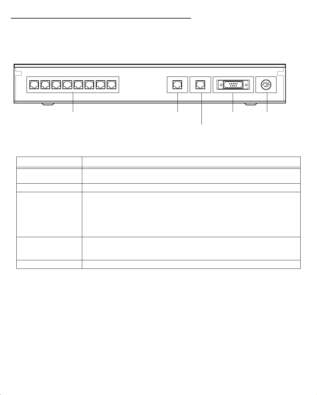
The figure below displays the back of the Netopia 4753 G.SHDSL Integrated Access Device.
Netopia 4753 back panel
12345 786
Telephone Extension ports
Extensions
DSLTelephone
DSL Line port
10/100
Ethernet
Console Power
Console port Power port
10/100 Ethernet port
The following table describes all the Netopia 4753 G.SHDSL Integrated Access Device back panel ports.
Port Description
Telephone extension
Eight RJ-11 telephone jacks for connecting your phone extensions.
ports
DSL port An RJ-45 10Base-T-style jack labeled DSL for your DSL connection.
Ethernet port An RJ-45 10/100Base-T Ethernet jack. You will use this to configure the Netopia
4753. For a new installation, use the Ethernet connection. Alternatively, you can
use the console connection to run console-based management using a direct
serial connection. You can either connect your computer directly the Ethernet
port using a crossover cable, or connect both your computer and the Netopia
4753 to an existing Ethernet hub on your LAN.
Console port A DB-9 console port for a direct serial connection to the console screens. You
can use this if you are an experienced user. See “Connecting a Console Cable
to Your Device” on page 6-3.
Power port A mini-DIN8 power adapter cable connection.
1. Connect the mini-DIN8 connector from the power adapter to the power port, and plug the other end into an
electrical outlet.
2. Connect one end of the RJ-45 cable to the DSL port, and the other end to your DSL wall outlet.
3. Connect the Ethernet cable to the Ethernet por t on the unit and the other end to your Ethernet hub.
You should now have: the power adapter plugged in; the Ethernet cable connected between the router and
your Ethernet hub; and the DSL cable connected between the router and the DSL wall outlet.
Page 23

Netopia 4753 Status Lights
The figure below represents the Netopia 4753 status light (LED) panel.
Netopia 4753 LED front panel
Making the Physical Connections 3-5
23 4 5
1 8 9 10 1112
Power
Error
Ethernet
DSL
6
7
Voice
The following table summarizes the meaning of the various LED states and colors:
When this happens... the LEDs...
The power is off (button is not pressed in) 1 is dark.
The power is on (button pressed in) 1 is green.
No errors are detected on any inter face 2 is dark.
Errors are detected on any inter face 2 is red.
The Ethernet inter face is operational 3 is green.
The Ethernet inter face is disabled 3 is dark.
The DSL WAN interface is inactive 4 is dark.
The DSL WAN interface is training 4 flashes green. Initially the LED is dark, then flashes
green while attempting to establish connection to the
DSLAM. While exchanging connection information with the
DSLAM, the LED flashes slightly faster.
The DSL WAN interface is trained 4 is solid green.
A phone is off-hook 5 through 12 are green for the corresponding extension.
A phone is on-hook 5 through 12 are dark for the corresponding extension.
Page 24

3-6 Administration Guide
Page 25

Sharing the Connection 4-1
CCCChhhhaaaapppptttteeeerrrr 44
SSSShhhhaaaarrrriiiinnnngggg tttthhhheeee CCCCoooonnnnnnnneeeeccccttttiiiioooonn
Once you have set up your physical local area network, you will need to configure the TCP/IP stack on each
client workstation connected to your Netopia 4753. This chapter describes how to configure TCP/IP for both
Windows-based and Macintosh computers.
This chapter explains the following topics:
■ “Configuring TCP/IP on Windows-based Computers” on page 4-2
■ “Configuring TCP/IP on Macintosh Computers” on page 4-5
44
nn
Page 26
4-2 Administration Guide
Configuring TCP/IP on Windows-based Computers
Configuring TCP/IP on a Windows computer requires the following:
■ An Ethernet card (also known as a network adapter)
■ The TCP/IP protocol must be “bound” to the adapter or card
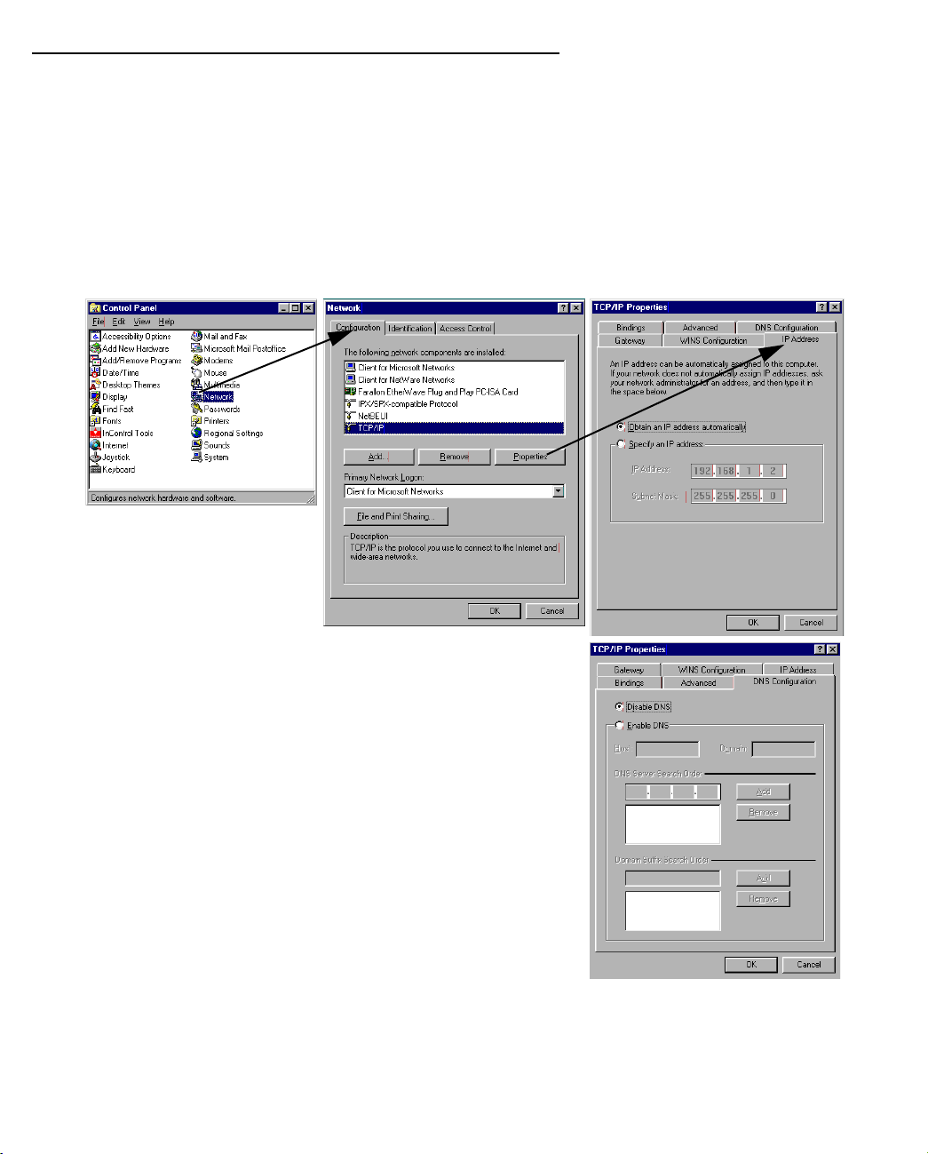
Dynamic configuration (recommended)
To configure your PC for dynamic addressing do the following:
1. Go to the Start
Menu/Settings/Control
Panels and double click
the Network icon. From
the Network components
list, select the
Configuration tab.
2. Select TCP/IP-->Your Network Card. Then select
Properties. In the TCP/IP Proper ties screen, select the IP
Address tab. Click “Obtain an IP Address automatically”.
3. Click on the DNS Configuration tab. Click Disable DNS.
DNS will be assigned by the router with DHCP.
Click on the Gateway tab, and if there is an installed
gateway, remove it.
4. Click OK in this window and the next window. When
prompted, reboot the computer.
Note: You can also use these instructions to configure other computers on your network to accept IP addresses
served by the Netopia 4753.
Page 27
Sharing the Connection 4-3
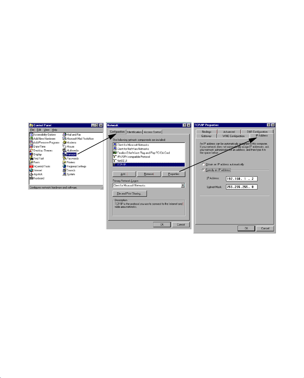
Static configuration (optional)
If you are manually configuring for a fixed or static IP address, per form the following:
1. Go to Start Menu/Settings/Control Panels and double click the Network icon. From the Network
components list, select the Configuration tab.
2. Select TCP/IP-->Your Network Card. Then select Properties. In the TCP/IP Proper ties screen, select the
IP Address tab. Click “Specify an IP Address.”
Enter the following:
IP Address: 192.168.1.2
Subnet Mask: 255.255.255.0
This address is an example of one that can be used to configure the router. Your ISP or network
administrator may ask you to use a different IP address and subnet mask.
Page 28
4-4 Administration Guide
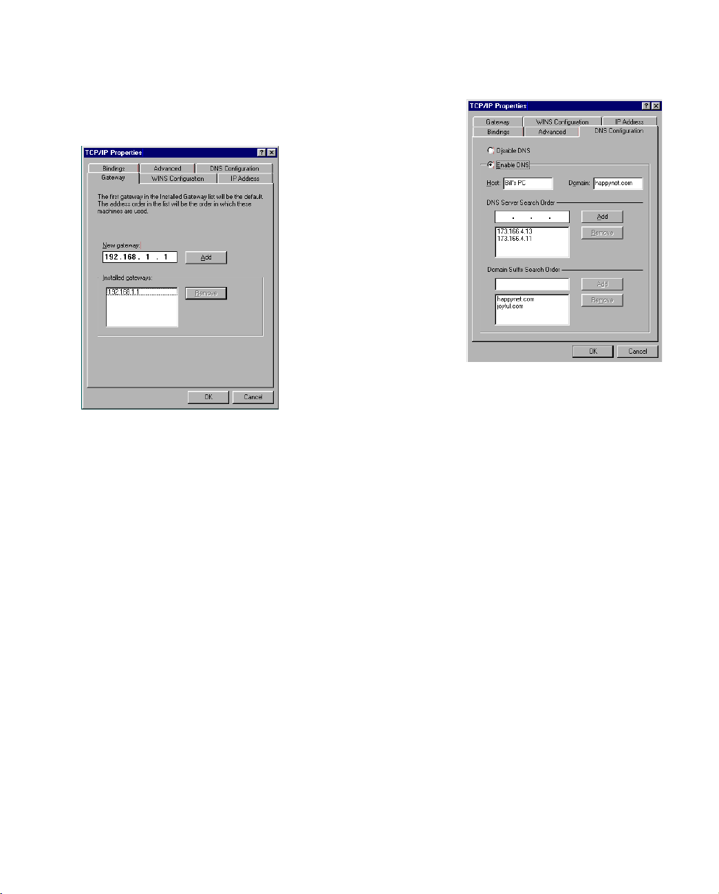
3. Click on the Gateway tab (shown below).
Under “New gateway,” enter
192.168.1.1. Click Add. This is the
Netopia 4753’s pre-assigned IP address.
4. Click OK in this window and the next window. When prompted, reboot the computer.
Click on the DNS Configuration tab. Click Enable DNS.
Enter the following
information:
Host: Type the name
you want to give to
this computer.
Domain: Type your
domain name. If you
don't have a domain
name, type your ISP's
domain name; for
example,
netopia.com.
DNS Server Search
Order: Type the
primary DNS IP
address given to you
by your ISP. Click
Add. Repeat this process for the secondary DNS.
Domain Suffix Search Order: Enter the same domain
name you entered above.
Note: You can also use these instructions to configure other computers on your network with manual or static
IP addresses. Be sure each computer on your network has its own IP address.
Page 29
Sharing the Connection 4-5
Configuring TCP/IP on Macintosh Computers
The following is a quick guide to configuring TCP/IP for MacOS computers. Configuring TCP/IP in a Macintosh
computer requires the following:
■ You must have either Open Transport or Classic Networking (MacTCP) installed.
Note: If you want to use the Dynamic Host Configuration Protocol (DHCP) server built into your Netopia
4753 to assign IP addresses to your Macintoshes, you must be running Open Transport, standard in
MacOS 8 and optional in earlier system versions. You can have your Netopia 4753 dynamically assign IP
addresses using MacTCP; however, to do so requires that the optional AppleTalk kit be installed which can
only be done after the router is configured.
■ You must have built-in Ethernet or a third-par ty Ethernet card and its associated drivers installed in your
Macintosh.
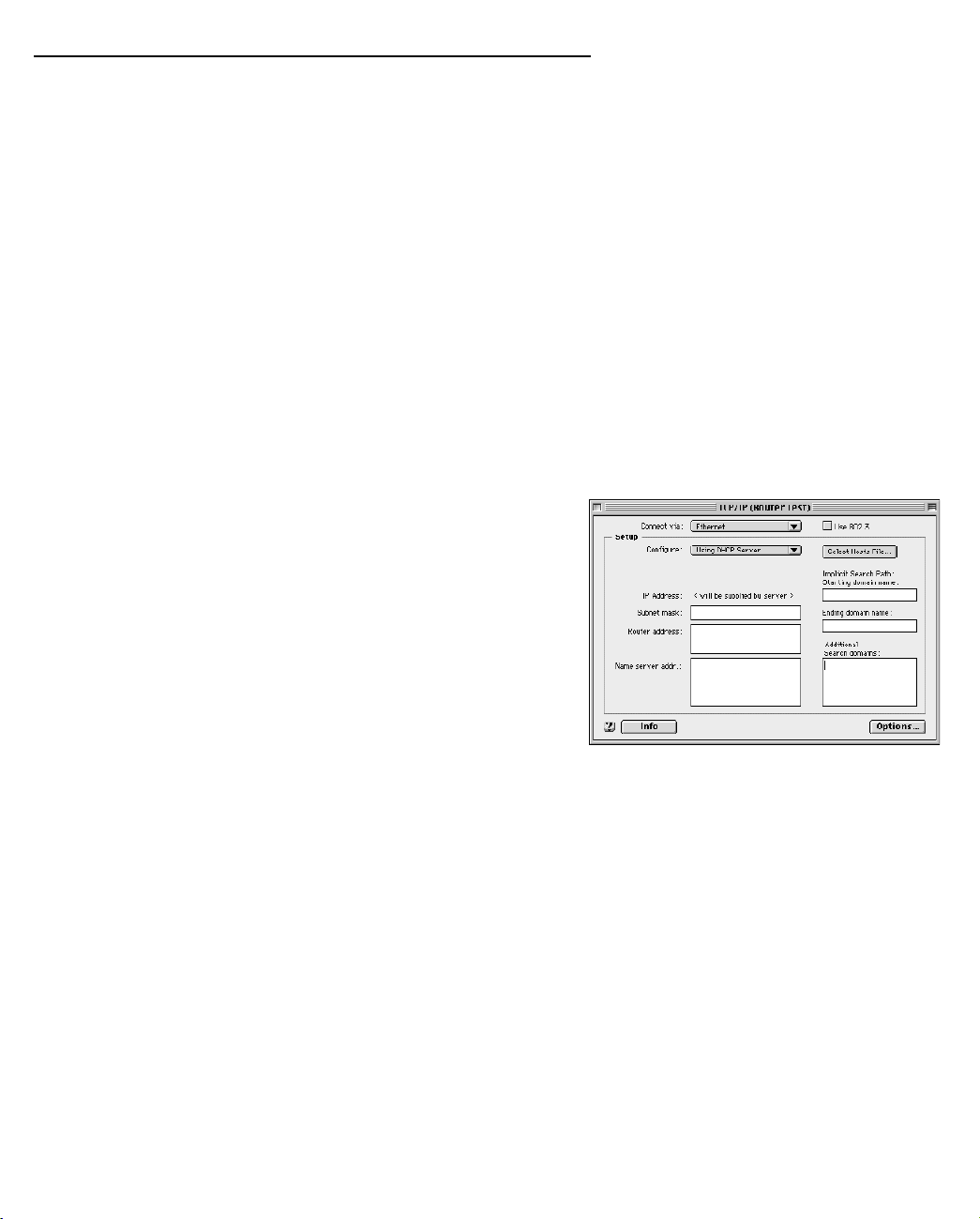
Dynamic configuration (recommended)
The Dynamic Host Configuration Protocol (DHCP), which enables dynamic addressing, is enabled by default in
the router. To configure your Macintosh computer for dynamic addressing do the following:
1. Go to the Apple menu. Select Control Panels and then
TCP/IP.
2. With the TCP/IP window open, go to the Edit menu and
select User Mode. Choose Basic and click OK.
3. In the TCP/IP window, select “Connect via: Ethernet” and
“Configure: Using DHCP Server.”
Note: You can also use these instructions to configure other computers on your network to accept IP addresses
served by the Netopia 4753.
Page 30
4-6 Administration Guide
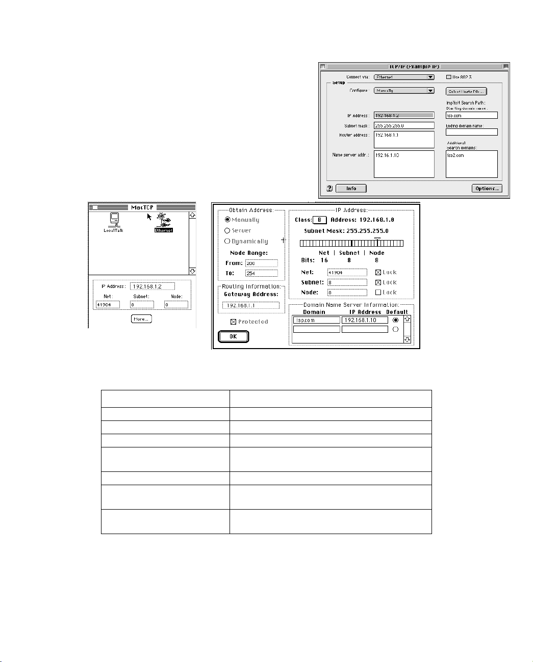
Static configuration (optional)
If you are manually configuring for a fixed or static IP address,
perform the following:
1. Go to the Apple menu. Select Control Panels and then
TCP/IP or MacTCP.
2. With the TCP/IP window open, go to the Edit menu and
select User Mode. Choose Advanced and click OK.
Or, in the MacTCP window, select Ethernet and click the
More button.
3. In the TCP/IP window or in the MacTCP/More window, select or type information into the fields as shown in
the following table.
Option: Select/Type:
Connect via: Ethernet
Configure: Manually
IP Address: 192.168.1.2
Subnet mask: 255.255.255.0, or for 12-user models
255.255.255.240
Router or Gateway address: 192.168.1.1
Name server address: Enter the primary and secondary name server
addresses given to you by your ISP
Implicit Search Path:
Starting domain name:
Enter your domain name; if you do not have a
domain name, enter the domain name of your ISP
4. Close the TCP/IP or MacTCP control panel and save the settings.
5. If you are using MacTCP, you must restar t the computer. If you are using Open Transport, you do not need
to restart.
Page 31

Sharing the Connection 4-7
Note: You can also use these instructions to configure other computers on your network with manual or static
IP addresses. Be sure each computer on your network has its own IP address.
More information about configuring your Macintosh computer for TCP/IP connectivity through a Netopia 4753
can be found in Technote NIR_026, “Open Transport and Netopia Routers,” located on the Netopia Web site.
Page 32

4-8 Administration Guide
Page 33

Connecting to Your Local Network 5-1
CCCChhhhaaaapppptttteeeerrrr 55
CCCCoooonnnnnnnneeeeccccttttiiiinnnngggg ttttoooo YYYYoooouuuurrrr LLLLooooccccaaaallll NNNNeeeettttwwwwoooorrrrkk
This chapter describes how to physically connect the Netopia 4753 to your local area network (LAN). Before you
proceed, make sure the Netopia 4753 is properly configured. You can customize the device’s configuration for
your particular LAN requirements using console-based management (see “Console-Based Management” on
page 6-1).
This section covers the following topics:
■ “Readying Computers on Your Local Network” on page 5-2
■ “Connecting to an IP and Telephone Network” on page 5-3
55
kk
Page 34

5-2 Administration Guide
Readying Computers on Your Local Network
PC and Macintosh computers must have certain components installed before they can communicate through
the Netopia 4753. The following illustration shows the minimal requirements for a typical PC or Macintosh
computer.
Application software
TCP/IP stack
Ethernet
Your PC
or Macintosh
computer
To the Netopia 4753
Application software: This is the software you use to send e-mail, browse the World Wide Web, read
newsgroups, etc. These applications may require some configuration. Examples include the Eudora e-mail client
and the Web browsers Microsoft Internet Explorer and Netscape Navigator.
TCP/IP stack: This is the software that lets your PC or Macintosh computer communicate using Internet
protocols. TCP/IP stacks must be configured with some of the same information you used to configure the
Netopia 4753. There are a number of TCP/IP stacks available for PC computers. Windows 95 includes a built-in
TCP/IP stack. See “Configuring TCP/IP on Windows-based Computers” on page 4-2. Macintosh computers use
either MacTCP or Open Transport. See “Configuring TCP/IP on Macintosh Computers” on page 4-5.
Ethernet: Ethernet hardware and software drivers enable your PC or Macintosh computer to communicate on
the LAN.
Once the Netopia 4753 is properly configured and connected to your LAN, PC and Macintosh computers that
have their required components in place will be able to connect to the Internet or other remote IP networks.
Page 35

Connecting to Your Local Network 5-3
Connecting to an IP and Telephone Network
The Netopia 4753 supports Ethernet connections through its Ethernet port. You can connect a standard 10 or
100Base-T Ethernet network to the Netopia 4753 using its Ethernet por t.
Netopia 4753 back panel
12345 786
Telephone Extension ports
Add computers by connecting
them to an Ethernet hub and
connecting the hub to the Ethernet
port on the Netopia 4753. Add
telephones or fax machines by
connecting them directly to the
telephone extension ports on the
Netopia 4753.
Extensions
DSL Line port
12345 786
DSLTelephone
10/100
Ethernet
Console port Power port
10/100 Ethernet port
10/
Co Po
DTel
Console Power
10/100Base-T
Hub
Note: The Ringer Equivalence Number (REN) is used to determine how many devices can be connected to your
telephone line. In most areas, the sum of the REN's of all devices on any one line should not exceed two (2.0).
If too many devices are attached, they many not ring properly. The REN for telephone devices is usually listed on
the product label or stamped or moulded into the body of the device.
Page 36

5-4 Administration Guide
Page 37

Console-Based Management 6-1
CCCChhhhaaaapppptttteeeerrrr 66
CCCCoooonnnnssssoooolllleeee----BBBBaaaasssseeeedddd MMMMaaaannnnaaaaggggeeeemmmmeeeennnntt
Console-based management is a menu-driven interface for the capabilities built into the Netopia 4753.
Console-based management provides access to a wide variety of features that the router suppor ts. You can
customize these features for your individual setup. This chapter describes how to access the console-based
management screens.
This section covers the following topics:
■ “Connecting through a Telnet Session” on page 6-2
■ “Connecting a Console Cable to Your Device” on page 6-3
■ “Navigating through the Console Screens” on page 6-5
Console-based management screens contain eight entry points to the Netopia 4753 configuration and
monitoring features. The entry points are displayed in the Main Menu shown below:
66
tt
Netopia 4753 v5.1
Easy Setup...
WAN Configuration...
System Configuration...
Voice Configuration...
Utilities & Diagnostics...
Statistics & Logs...
Quick Menus...
Quick View...
Return/Enter goes to Easy Setup -- minimal configuration.
You always start from this main screen.
■ The Easy Setup menus display and permit changing the values contained in the default connection profile.
You can use Easy Setup to initially configure the router directly through a console session.
Easy Setup menus contain up to five descendant screens for viewing or altering these values. The number
of screens depends on whether you have optional features installed.
■ The WAN Configuration menu displays and permits changing your connection profile(s) and default profile,
creating or deleting additional connection profiles, and configuring or reconfiguring the manner in which you
Page 38

6-2 Administration Guide
may be using the router to connect to more than one ser vice provider or remote site.
■ The System Configuration menus display and permit changing:
■ Internet protocol setup. See “IP Setup” on page 10-1.
■ Filter sets (firewalls). See “Security” on page 13-1.
■ IP address serving. See “IP Address Ser ving” on page 10-10.
■ Date and time. See “Date and time (Network Time Protocol)” on page 9-17.
■ Console configuration. See “Connecting a Console Cable to Your Device” on page 6-3.
■ SNMP (Simple Network Management Protocol). See “SNMP” on page 14-13.
■ Security. See “Security” on page 13-1.
■ Upgrade feature set. See “Upgrade feature set” on page 9-20.
■ The Voice Configuration menus provide the tools for configuring the voice telephone features available in
the Netopia 4753. See Chapter 8, “Voice Configuration.”
■ The Utilities & Diagnostics menus provide a selection of seven tools for monitoring and diagnosing the
router's behavior, as well as for updating the firmware and rebooting the system. See “Utilities and
Diagnostics” on page 15-1 for detailed information.
■ The Statistics & Logs menus display nine sets of tables and device logs that show information about your
router, your network, and their history. See “Statistics & Logs” on page 14-4 for detailed information.
■ The Quick Menus screen is a shortcut entr y point to 22 of the most commonly used configuration menus
that are accessed through the other menu entr y points.
■ The Quick View menu displays at a glance current real-time operating information about your router. See
“Quick View Status Overview” on page 14-1 for detailed information.
Connecting through a Telnet Session
Features of the Netopia 4753 can be configured through the console screens.
Before you can access the console screens through Telnet, you must have:
■ A network connection locally to the router or IP access to the router.
Note: Alternatively, you can have a direct serial console cable connection using the provided console cable for
your platform (PC or Macintosh) and the Console por t on the back of the router. For more information on
attaching the console cable, see “Connecting a Console Cable to Your Device” on page 6-3.
■ Telnet software installed on the computer you will use to configure the router
Configuring Telnet software
If you are configuring your router using a Telnet session, your computer must be running a Telnet software
program.
■ If you connect a PC with Microsoft Windows, you can use a Windows Telnet application or simply run Telnet
Page 39
Console-Based Management 6-3
from the Start menu.
■ If you connect a Macintosh computer, you can use the NCSA Telnet program supplied on the Netopia 4753
CD. You install NCSA Telnet by simply dragging the application from the CD to your hard disk.
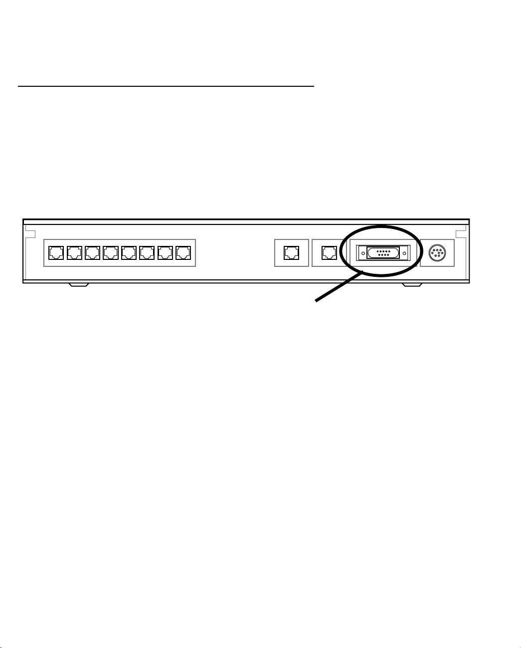
Connecting a Console Cable to Your Device
You can perform all of the system configuration activities for your Netopia 4753 through a local serial console
connection using terminal emulation software, such as HyperTerminal provided with Windows 95, 98, 2000, or
NT on the PC, or ZTerm for Classic MacOS or MacOSX, included on the Netopia CD, for Macintosh computers.
The Netopia 4753 back panel has a connector labeled “Console” for attaching the Router to either a PC or
Macintosh computer via the serial port on the computer. (On a Macintosh computer, the serial por t is called the
Modem port or Printer port.) This connection lets you use the computer to configure and monitor the Netopia
4753 via the console screens.
Netopia 4753 back panel
12345 786
Extensions
DSLTelephone
10/100
Ethernet
Console Power
Console connection port
DB-9 (male)
To connect the Netopia 4753 to your computer for serial console communication, use a console cable
appropriate to your platform:
■ A DB-9 connector end attaches to a PC.
■ A mini-DIN8 or a USB connector end attaches to a Macintosh computer depending on your computer’s
serial bus type. Since Macintosh computers have different serial bus connectors, you will need a
mini-DIN8- or USB-to-DB-9 adapter. These are available from a variety of third-party manufacturers.
■ A DB-9 end of the Console cable attaches to the Netopia 4753’s Console port.
■ If you connect a PC with Microsoft Windows 95, 98, 2000 or NT, you can use the HyperTerminal application
bundled with the operating system.
■ If you connect a Macintosh computer, you can use the ZTerm terminal emulation program on the supplied
Netopia 4753 CD.
Page 40

6-4 Administration Guide
Launch your terminal emulation software and configure the communications software for the values shown in
the table below. These are the default communication parameters that the Netopia 4753 uses.
Parameter Suggested Value
Terminal type PC: ANSI-BBS
Mac: ANSI, VT-100, or VT-200
Data bits 8
Parity None
Stop bits 1
Speed 9600 bits per second (can be set for up to 57600)
Flow Control None
Note: The router firmware contains an autobaud detection feature. If you are at any
screen on the serial console, you can change your baud rate and press Return
(HyperTerminal for the PC requires a disconnect). The new baud rate is displayed at
the bottom of the screen.
Page 41

Console-Based Management 6-5
Navigating through the Console Screens
Use your keyboard to navigate the Netopia 4753’s configuration screens, enter and edit information, and make
choices. The following table lists the keys to use to navigate through the console screens.
To... Use These Keys...
Move through selectable items in a screen or pop-up menu Up, Down, Left, and Right Arrow
Set a change to a selected item or open a pop-up menu of
options for a selected item like entering an upgrade key
Change a toggle value (Yes/No, On/Off) Tab
Restore an entry or toggle value to its previous value Esc
Move one item up Up arrow or Control + K
Move one item down Down arrow or Control + O
Display a dump of the device event log Control + E
Display a dump of the WAN event log Control + F
Refresh the screen Control + L
Return or Enter
Page 42

6-6 Administration Guide
Page 43

Easy Setup 7-1
CCCChhhhaaaapppptttteeeerrrr 77
EEEEaaaassssyyyy SSSSeeeettttuuuupp
This chapter describes how to use the Easy Setup console screens on your Netopia 4753 G.SHDSL Integrated
Access Device. After completing the Easy Setup console screens, your device will be ready to connect to the
Internet or another remote site.
77
pp
Easy Setup Console Screens
Using five Easy Setup console screens, you can:
■ Modify a connection profile for your device for the connection to your ISP or remote location
■ Set up the voice connection to your remote voice provider
■ Set up IP addresses and IP address ser ving
■ Password–protect configuration access to your Netopia 4753 G.SHDSL Integrated Access Device
Accessing the Easy Setup console screens
To access the console screens, Telnet to the Netopia 4753 over your Ethernet network or physically connect
with a serial console cable and access it with a terminal emulation program. See “Connecting through a Telnet
Session” on page 6-2 or “Connecting a Console Cable to Your Device” on page 6-3.
Note: Before continuing, make sure you have the information that your telephone ser vice provider, ISP, or
network administrator has given you for configuring the Netopia 4753.
The Netopia 4753’s first console screen, Main Menu, appears in the terminal emulation window of the attached
PC or Macintosh computer when:
■ The Netopia 4753 is turned on
■ The computer is connected to the Netopia 4753
■ Telnet or the terminal emulation software is running and configured correctly
Page 44

7-2 Administration Guide
A screen similar to the following Main Menu appears:
Netopia 4753 v5.1
Easy Setup...
WAN Configuration...
System Configuration...
Voice Configuration...
Utilities & Diagnostics...
Statistics & Logs...
Quick Menus...
Quick View...
Return/Enter goes to Easy Setup -- minimal configuration.
You always start from this main screen.
If you do not see the Main Menu, verify that:
■ If you are using a serial connection, that your serial port speed is the same as the Netopia 4753’s default
9600 baud, for first use.
■ The computer used to view the console screen has its serial port connected to the Netopia 4753’s
Console port or an Ethernet connection to one of its Ethernet por ts. See “Connecting a Console Cable to
Your Device” on page 6-3 or “Connecting through a Telnet Session” on page 6-2.
■ Telnet or the terminal emulation software is configured for the recommended values.
■ If you are connecting via the Console port, your computer’s serial por t is not being used by another device,
such as an internal modem, or an application. Turn off all other programs (other than your terminal
emulation program) that may be interfering with your access to the por t.
■ You have entered the correct password, if necessary. Your Netopia 4753’s console access may be
password protected from a previous configuration. See your system administrator to obtain the password.
See Appendix A, “Troubleshooting,” for more suggestions.
■ If all you see is a pound sign (#), you are in the command line interface. Hit Control-N to exit to the Main
Menu.
Page 45

Easy Setup 7-3
Quick Easy Setup Connection Path
This section may be all you need to do to configure your Netopia 4753 G.SHDSL Integrated Access Device to
connect to the Internet.
Your service provider must supply you with several parameter values for you to enter in the device. The ser vice
provider will provide values for the parameters shown below:
Parameter: Default value: Your value:
DSL Line Configuration Screen
Regional Setting Annex A (default) or Annex B
Data Link Encapsulation PPP or RFC1483 (default)
PPP Mode VC Multiplexed (default) or
LLC SNAP
RFC1483 Mode Bridged 1483 (default)
or Routed 1483
PPP over Ethernet (PPPoE)
(for Bridged 1483 only)
Data Circuit VPI
Data Circuit VPI
(for ATM WAN DSL Mode only)
Off (default) or On
0-255 (8 is default)
0-65535 (35 is default)
Voice Easy Setup Screen
Voice Gateway CopperCom,
JetStream,
TollBridge,
TDSoft
or Zhone
Voice VPI
Voice VCI
(for any Voice Gateway other
than TollBridge)
Address Translation Enabled Yes (default) or No
IP Addressing Unnumbered or Numbered
Local WAN IP Address
Local WAN IP Mask
Remote IP Address
Remote IP Mask
PPP Authentication None (default), PAP or CHAP
User Name (or Host Name) n/a
0-255 (0 is default)
0-65535 (0 is default)
Easy Setup Profile Screen
(default)
n/a
n/a
Page 46

7-4 Administration Guide
Parameter: Default value: Your value:
Password (or Secret) n/a
IP Easy Setup Screen
Ethernet IP Address
Ethernet Subnet Mask
192.168.1.1
255.255.255.0
Domain Name n/a
Primary Domain Name Server n/a
Secondary Domain Name
n/a
Server
Default IP Gateway n/a
Easy Setup Security Configuration Screen
Write Access Name n/a
Write Access Password n/a
(If you want to record these values, you can print these pages and use the spaces above.)
If your provider assigns your device a Static IP address, do the following:
1. Open a Telnet session to 192.168.1.1 to bring up the Main Menu.
If you don't know how to do this, see “Connecting through a Telnet Session” on page 6-2.
Alternatively, you can connect the console cable and open a direct serial console connection, using a
terminal emulator program. See “Connecting a Console Cable to Your Device” on page 6-3.
The Main Menu appears.
Netopia 4753 v5.1
Easy Setup...
WAN Configuration...
System Configuration...
POTS Configuration...
Utilities & Diagnostics...
Statistics & Logs...
Quick Menus...
Quick View...
Return/Enter goes to Easy Setup -- minimal configuration.
You always start from this main screen.
Page 47

Easy Setup 7-5
2. Select the first item on the Main Menu list, Easy Setup. Press Return to bring up the DSL Line
Configuration menu screen.
DSL Line Configuration
DSL Line Configuration
Regional Setting... Annex A
Data Link Encapsulation... RFC1483
RFC1483 Mode... Bridged 1483
PPP over Ethernet (PPPoE): Off
Data Circuit VPI (0-255): 8
Data Circuit VCI (0-65535): 35
PREVIOUS SCREEN NEXT SCREEN
3. Select Regional Setting and from the pop-up menu select either Annex A or Annex B. North American users
select Annex A; non-North American users select Annex B.
4. Select Data Link Encapsulation and from the pop-up menu choose your DLE.
■ If you selected RFC1483, the next pop-up menu RFC1483 Mode offers the choice of Bridged 1483 or
Routed 1483. If you select Bridged 1483, a new option PPP over Ethernet (PPPoE) appears. You can
then toggle PPPoE On or Off. Choosing Routed 1483 hides the PPPoE option.
■ If you selected PPP, the next pop-up menu PPP Mode offers the choice of VC Multiplexed or LLC SNAP.
5. The next two fields, Data Circuit VPI and Data Circuit VCI are editable. Enter the Vir tual Path Identifier and
Virtual Channel Identifier values that your provider specifies. For more information on VPIs and VCIs, see
“Multiple ATM Permanent Virtual Circuit Support” on page 9-3.
6. Press the Down arrow key until you reach NEXT SCREEN. Press Return to bring up the next screen.
Page 48

7-6 Administration Guide
Voice Easy Setup
Voice Easy Setup
+------------+
+------------+
Voice Gateway... | CopperCom |
| JetStream |
Voice VPI (0-255): | TollBridge |
Voice VCI (0-65535): | TDSoft |
| Zhone |
+------------+
PREVIOUS SCREEN NEXT SCREEN
1. Select Voice Gateway and press Return. The pop-up menu will offer you the choice of popular voice
gateway devices. Your selection depends on which type your ISP uses: CopperCom, JetStream, TollBridge,
TDSoft, or Zhone.
2. For any Voice Gateway other than Tollbridge, the Voice VPI and Voice VCI fields are editable. (If you select
Tollbridge, the VPI and VCI fields do not appear.) Enter the Virtual Path Identifier and Virtual Channel
Identifier values that your provider specifies. For more information on VPIs and VCIs, see “Multiple ATM
Permanent Vir tual Circuit Support” on page 9-3.
3. Press the Down arrow key until you reach NEXT SCREEN. Press Return to bring up the next screen.
Page 49

Easy Setup 7-7
Easy Setup Profile
The Easy Setup Profile screen is where you configure the parameters that control the Netopia 4753’s
connection to a specific remote destination, usually your ISP or a corporate site.
On a Netopia 4753 G.SHDSL Integrated Access Device you can add up to 15 more connection profiles, for a
total of 16, although, except for Virtual Private Networks, you can only use one at a time.
Connection Profile 1: Easy Setup Profile
Address Translation Enabled: Yes
IP Addressing... Numbered
Local WAN IP Address: 0.0.0.0
Remote IP Address: 127.0.0.2
Remote IP Mask: 255.255.255.255
PPP Authentication... PAP
Send User Name: jarjar
Send Password: binks
PREVIOUS SCREEN NEXT SCREEN
Return accepts * ESC cancels * Left/Right moves insertion point * Del deletes.
Enter basic information about your WAN connection with this screen.
1. To enable address translation, toggle Address Translation Enabled to Ye s (the default). For more
information on Network Address Translation, see Chapter 10, “IP Setup,” on page 10-1.
The IP Addressing menu item allows you to choose between Unnumbered and Numbered addressing.
Numbered is the default for DSL. It assigns a unique IP address to the DSL WAN interface, as required by
most ISPs’ routers. Unnumbered may be used for simpler configurations such as point-to-point short haul
applications.
2. Select the editable field labeled Local WAN IP Address.
The default address is 0.0.0.0, which allows for dynamic addressing, when your ISP assigns an address
each time you connect. However, you can enter another specific address if you want to use static
addressing. In that case, enter the local WAN address your ISP gave you. Press Return.
3. If you selected PPP data link encapsulation in the DSL Line Configuration screen, a PPP Authentication
menu item appears. The authentication protocol and user name/password combinations you enter must
be assigned or agreed to in advance between you and your ISP. Select PPP Authentication and press
Return.
From the pop-up menu that appears, select the authentication method your ISP uses: PAP (Password
Authentication Protocol), CHAP (Challenge Handshake Authentication Protocol), or None.
■ PAP is the most common, and requires you to enter a User Name and Password in the next two fields.
■ CHAP requires you to enter a Host Name and Secret in the next two fields.
4. Press the Down arrow key until you reach NEXT SCREEN. Press Return to bring up the next screen.
Page 50

7-8 Administration Guide
IP Easy Setup
The IP Easy Setup screen is where you enter information about your Netopia Router’s:
■ Ethernet IP address
■ Ethernet Subnet mask
■ Domain Name
■ Domain Name Server IP address
■ Default gateway IP address
Consult with your network administrator to obtain the information you will need. For more information about
setting up IP, see “IP Setup” on page 10-1.
IP Easy Setup
Ethernet IP Address: 192.168.1.1
Ethernet Subnet Mask: 255.255.255.0
Domain Name: isp.net
Primary Domain Name Server: 209.3.224.21
Secondary Domain Name Server: 209.3.224.20
Default IP Gateway: 127.0.0.2
IP Address Serving: On
Number of Client IP Addresses: 100
1st Client Address: 192.168.1.100
PREVIOUS SCREEN NEXT SCREEN
Enter an IP address in decimal and dot form (xxx.xxx.xxx.xxx).
Set up the basic IP & IPX attributes of your Netopia in this screen.
1. Select Ethernet IP Address and enter the first IP address from the IP address range your ISP has given
you. This will be the Netopia Router’s IP address.
The Ethernet IP Address defaults to an address (192.168.1.1) within a range reser ved by the Internet
address administration authority for use within private networks.
Because this is a private network address, it should never be directly connected to the Internet. Using NAT
for all your connection profiles will ensure this restriction. See “Multiple Network Address Translation” on
page 11-1 of this guide for more information.
2. Select Ethernet Subnet Mask and enter the subnet mask your ISP has given you. The Ethernet Subnet
Mask defaults to a standard class mask derived from the class of the Ethernet IP address you entered in
the previous step.
3. Press the Down arrow key until the editable field labeled Domain Name is highlighted.
4. Type the Domain Name your ISP gave you. Press Return. The next field Primary Domain Name Server will
be highlighted.
Page 51

Easy Setup 7-9
5. Type the Primary Domain Name Server address your ISP gave you. Press Return. A new field Secondary
Domain Name Server will appear. If your ISP gave you a secondary domain name server address, enter it
here. Press Return until the next field Default IP Gateway is highlighted.
6. If you do not enter a Default IP Gateway value, the router defaults to the remote IP address you entered in
the Easy Setup connection profile. If the device does not recognize the destination of any IP traffic, it
forwards that traffic to this gateway.
Do not confuse the remote IP address and the Default IP Gateway’s address with the block of local IP
addresses you receive from your ISP. You use the local IP addresses for the Netopia 4753’s Ethernet port
and for IP clients on your local network. The remote IP address and the default gateway’s IP address
should point to your ISP’s router.
7. Toggle IP Address Serving to On or Off, depending on whether you want the device’s IP address ser ver to
supply dynamic IP addresses to your client workstations. Normally, you would accept the default On so that
workstations on your LAN can use a single IP address assigned by your ISP to connect to the Internet.
8. The IP address server will provide 100 IP addresses automatically to workstations on your LAN. You only
need to change the Number of Client IP Addresses if you have some other IP addressing scheme.
9. By default, the 1st Client Address is 192.168.1.100, based on the device’s default IP address of
192.168.1.1. You only need to change this if you have some other IP addressing scheme.
10. Press the Down arrow key until you reach NEXT SCREEN. Press Return.
Easy Setup Security Configuration
The Easy Setup Security Configuration screen lets you password-protect your Netopia 4753. Input your Write
Access Name and Write Access Password with names or numbers totaling up to eleven digits.
If you password protect the console screens, you will be prompted to enter the name and password you have
specified every time you log in to the console screens. Do not forget your name and password. If you do, you
will be unable to access any of the configuration screens.
Additional security features are available. See “Security” on page 13-1.
Page 52

7-10 Administration Guide
Easy Setup Security Configuration
It is strongly suggested that you password-protect configuration access to your
Netopia. By entering a Name and Password pair here, access via serial,
Telnet, and SNMP will be password-protected.
Be sure to remember what you have typed here, because you will be prompted for
it each time you configure this Netopia.
You can remove an existing Name and Password by clearing both fields below.
Write Access Name:
Write Access Password:
PREVIOUS SCREEN TO MAIN MENU RESTART DEVICE
Configure a Configuration Access Name and Password here.
The final step in configuring the Easy Setup console screens is to restart the Netopia 4753, so that the
configuration settings take effect.
1. Select RESTART DEVICE. A prompt asks you to confirm your choice.
2. Select CONTINUE to restart the Netopia Router and have your selections take effect.
Note: You can also restart the system at any time by using the Restar t System menu item (see “Restar ting the
System” on page 15-12) or by turning the Netopia Router off and on with the power switch.
The Router will restart and your configuration settings will be activated. You can then Exit or Quit your Telnet
application.
Easy Setup is now complete.
Page 53

Voice Configuration 8-1
CCCChhhhaaaapppptttteeeerrrr 88
VVVVooooiiiicccceeee CCCCoooonnnnffffiiiigggguuuurrrraaaattttiiiioooonn
This chapter describes the telephony services and configuration of the Netopia 4753 G.SHDSL Integrated
Access Device. For specific details on configuration and use of the Netopia 4753’s Internet connection, refer to
Chapter 7, “Easy Setup” and Chapter 9, “WAN and System Configuration.”
This chapter covers the following topics:
■ “Introduction” on page 8-1
■ “Configuring the Voice Features” on page 8-2
IIIInnnnttttrrrroooodddduuuuccccttttiiiioooonn
The Netopia 4753 provides small and medium sized businesses with a complete Centrex PBX system. It
supports voice call switching between the SDSL link and eight local extensions. Call management features can
include distinctive ringing, intelligent call forwarding, Direct Inward Dial (DID), Caller ID, and hunt groups.
Important key system features such as call hold, call transfer, and call waiting are all supported.
Note: Since the Netopia 4753 is a Centrex-based IAD, specific voice features available to you via the Netopia
4753 will depend on the services for which you contract with your service provider.
88
nn
nn
The Netopia 4753 supports up to eight telephone extensions and up to eight derived voice lines. Like the rest
of the 4700-series line, the Netopia 4753 includes the Netopia data routing engine for any number of attached
computers or other network devices connected to a single 10/100 Ethernet port.
Key features include:
■ Fax/Modem: Configurable Voice port for incoming fax or modem calls. This is another term for echo
cancellation support.
■ Voice Gateway Interoperability: CopperCom, JetStream, Tollbridge TDSoft, Zhone. General Bandwidth
support to follow in an upcoming firmware release.
Centrex is a simpler variation on the PBX. It is a PBX with all switching occurring at a local telephone of fice
instead of at the company's premises. Typically, the telephone company owns and manages all the
communications equipment necessary to implement the PBX and then sells various services to the company.
EEEExxxxppppllllaaaannnnaaaattttiiiioooonnnn ooooffff tttteeeerrrrmmmmss
Some telephony terms mean different things in Centrex mode and PBX/local switching mode: Toll Restriction,
Speed Dial, and Distinctive Ringing. The Netopia 4753 operates in Centrex mode.
■ Toll Restriction Operation - Centrex Mode: When you pick up the phone, you receive a dial tone from the
central office. When 9 is pressed, the Netopia 4753 detects 9 and returns a busy tone (locally generated).
Incoming calls are allowed. This allows local extension calling through the central office, but not long
ss
Page 54

8-2 Administration Guide
distance or local calls.
Toll Restriction Operation - PBX/Local Switching Mode: When you pick up the phone, you receive local PBX
dial tone. When a 9 (or outside line code) is pressed, the IAD detects the digit and returns busy (locally
generated). Incoming calls are allowed. Extension calls (locally switched) are allowed.
■ Speed Dial - Centrex Mode: In Centrex Mode, when you pick up the phone, dial-tone from the central office
is present. It is therefore, not possible to program the phone or use speed dial in this mode from the
phone.
Speed Dial - PBX/Local Switching mode: In this mode, you have the ability to pick up the phone, receive
local dial tone and proceed to program the phone w/ local speed dial options. In addition, taking the phone
off hook and pressing speed dial numbers will cause the stored speed dial digits to be sent out. This is
independent of the previous mode.
CCCCoooonnnnffffiiiigggguuuurrrriiiinnnngggg tttthhhheeee VVVVooooiiiicccceeee FFFFeeeeaaaattttuuuurrrreeeess
ss
This section describes how to configure the voice telephone features of the Netopia 4753.
From the Main Menu select Voice Configuration.
Netopia 4753 v5.1
Easy Setup...
WAN Configuration...
System Configuration...
Voice Configuration...
Utilities & Diagnostics...
Statistics & Logs...
Quick Menus...
Quick View...
Return/Enter goes to Easy Setup -- minimal configuration.
You always start from this main screen.
The Voice Configuration screen appears.
Page 55

Voice Configuration 8-3
Voice Configuration
Voice Gateway... CopperCom
Ring Cadence... 20 Hz
Port Configuration...
Voice Coding... mu-law
LES Profile Number... Profile 9
■ Select Voice Gateway and from the pop-up menu, choose the type of voice gateway device to which you will
be connected. The choices are: CopperCom, JetStream, TollBridge, TDSoft, or Zhone.
■ Select Ring Cadence and press Return. A pop-up menu allows you to choose between 20Hz (the default)
and 25Hz for compliance with several non-North American telephone systems.
■ Selecting Port Configuration displays the Por t Configuration screen.
Port Configuration
Port 1 Echo Cancellation Enabled: Yes
Compression is G726 - ADPCM 32K
Port 2 Echo Cancellation Enabled: Yes
Compression is G726 - ADPCM 32K
Port 3 Echo Cancellation Enabled: Yes
Compression is G726 - ADPCM 32K
Port 4 Echo Cancellation Enabled: Yes
Compression is G726 - ADPCM 32K
Port 5 Echo Cancellation Enabled: Yes
Compression is G726 - ADPCM 32K
Port 6 Echo Cancellation Enabled: Yes
Compression is G726 - ADPCM 32K
Port 7 Echo Cancellation Enabled: Yes
Compression is G726 - ADPCM 32K
Port 8 Echo Cancellation Enabled: Yes
Compression is G726 - ADPCM 32K
Return/Enter accepts * Tab toggles * ESC cancels.
Page 56

8-4 Administration Guide
Echo cancellation is set to Yes by default. For ordinar y telephone handsets, echo cancellation should be
set to Yes (turned on) to eliminate echoes on the voice line. Toggling a port to No allows you to connect a
fax machine or modem to the phone port (since fax machines and modems automatically cancel echoes).
If you want to disable echo cancellation, toggle this item to No. You can enable or disable echo cancellation
for each port on the Netopia 4753.
■ The Compression type is normally set at the voice gateway. It is visible for informational purposes, to
ascertain that the provisioning on the voice gateway is in sync with the Netopia 4753.
LES stands for Loop Emulation Service, an increasingly popular standard among ATM voice gateway
manufacturers.
If the voice gateway is LES-compliant, a pop-up menu allows you to choose between G711 - PCM 64K and
G726 - ADPCM 32K. Your service provider must supply you with the correct provisioning information. The
reason is that in those gateway types the voice gateway expects this type of provisioning to be done prior
to making any voice calls.
If the voice gateway is not LES-compliant, the pop-up menus are not available, and these fields are for
information only.
Once you have made your settings for each voice port, press Escape to return to the Voice Configuration
menu.
■ Select Voice Coding and press Return. From the pop-up menu choose the voice coding method you will be
using. The default is mu-law, which is the standard 8-bit, 8 kHz, mono format intended primarily for the
requirements of voice in North America. You can also choose a-law, a more common audio format outside
North America.
■ If your service provider is using an LES-compliant voice gateway, the LES Profile Number option becomes
visible. From the pop-up menu choose either Profile 9 or Profile 10.
The Netopia 4753 currently suppor ts LES profile 9 and LES profile 10. LES profile 9 includes only PCM
calls. LES profile 10 includes PCM and ADPCM capabilities.
Page 57

PPPPaaaarrrrtttt IIIIIIII:::: AAAAddddvvvvaaaannnncccceeeedddd CCCCoooonnnnffffiiiigggguuuurrrraaaattttiiiioooonn
nn
Page 58

Administration Guide
Page 59

WAN and System Configuration 9-1
CCCChhhhaaaapppptttteeeerrrr 99
WWWWAAAANNNN aaaannnndddd SSSSyyyysssstttteeeemmmm CCCCoooonnnnffffiiiigggguuuurrrraaaattttiiiioooonn
This chapter describes how to use the console-based management screens to access and configure advanced
features of your Netopia 4753 G.SHDSL Integrated Access Device. You can customize these features for your
individual setup. These menus provide a powerful method for experienced users to set up their device’s
connection profiles and system configuration.
This section covers the following topics:
■ “WAN Configuration” on page 9-2
■ “Multiple ATM Permanent Virtual Circuit Support” on page 9-3
■ “Creating a New Connection Profile” on page 9-10
■ “The WAN Default Profile” on page 9-13
■ “The ATMP/PPTP Default Profile” on page 9-15
■ “System Configuration Screens” on page 9-15
■ “System Configuration Features” on page 9-16
99
nn
Page 60

9-2 Administration Guide
WAN Configuration
To configure your Wide Area Network (WAN) connection, navigate to the WAN Configuration screen from the Main
Menu and select WAN Configuration, then WAN (Wide Area Network) Setup.
Main
Menu
The DSL Line Configuration screen appears.
DSL Line Configuration
Regional Setting... Annex A
Clock Source... Network
Cell Format... Scrambled
Unused Cell Format... Idle
Data Link Encapsulation... RFC1483
RFC1483 Mode... Bridged 1483
PPP over Ethernet (PPPoE): Off
Display/Change Circuit...
Add Circuit...
Delete Circuit...
WAN
Configuration
WAN
Setup
Each access concentrator (DSLAM) has a different set of defaults and other parameters.
Your service provider should supply you with the appropriate information about the type and capabilities of the
access concentrator equipment they use.
■ Select Regional Setting and from the pop-up menu select either Annex A or Annex B. North American users
select Annex A; non-North American users select Annex B.
■ Select Clock Source and from the pop-up menu select either Network (the default) or Internal.
■ Select Cell Format and from the pop-up menu select either Scrambled (the default) or Unscrambled. This
setting must match the format used by your ser vice provider. Scrambled is the most common, so you
probably do not need to change it unless your provider specifically tells you to do so.
■ Select Unused Cell Format and from the pop-up menu select either Idle (the default) or Empty. This setting
must match the format used by your ser vice provider. Idle is the most common, so you probably do not
Page 61

WAN and System Configuration 9-3
need to change it unless your provider specifically tells you to do so.
■ Select Data Link Encapsulation and from the pop-up menu choose your DLE.
■ If you selected RFC1483, the next pop-up menu RFC1483 Mode offers the choice of Bridged 1483 or
Routed 1483. If you select Bridged 1483, a new option PPP over Ethernet (PPPoE) appears. You can
then toggle PPPoE On or Off. Choosing Routed 1483 hides the PPPoE option.
■ If you selected PPP, the next pop-up menu PPP Mode offers the choice of VC Multiplexed or LLC SNAP.
■ If you selected ATM WAN DSL Mode, the next three fields, Display/Change Circuit, Data Circuit VPI, and
Data Circuit VCI are editable. Other wise they do not appear. Enter the Virtual Path Identifier and Virtual
Channel Identifier values that your provider specifies. For more information on VPIs and VCIs, see “Multiple
ATM Permanent Virtual Circuit Support” below.
MMMMuuuullllttttiiiipppplllleeee AAAATTTTMMMM PPPPeeeerrrrmmmmaaaannnneeeennnntttt VVVViiiirrrrttttuuuuaaaallll CCCCiiiirrrrccccuuuuiiiitttt SSSSuuuuppppppppoooorrrrtt
tt
The Netopia 4753 supports up to eight permanent vir tual circuits.
MMMMuuuullllttttiiiipppplllleeee AAAATTTTMMMM PPPPVVVVCCCC oooovvvveeeerrrrvvvviiiieeeeww
ww
On cell-based DSL WAN interfaces, the ATM connection between the device and the central office equipment
(DSLAM) is divided logically into one or more virtual circuits (VCs). A vir tual circuit may be either a permanent
virtual circuit (PVC) or a switched vir tual circuit (SVC). Netopia devices support PVCs.
VCs are identified by a Virtual Path Identifier (VPI) and Vir tual Channel Identifier (VCI). A VPI is an 8-bit value
between 0 and 255, inclusive, while a VCI is a 16-bit value between 0 and 65535, inclusive.
■ Circuits now support attributes in addition to their VPI and VCI values. When configuring a circuit, you can
specify an optional circuit name of up to 14 characters. The circuit name is used only to identify the circuit
for management purposes as a convenience to aid in selecting circuits from lists. The default circuit name
is “Circuit <n>”, where <n> is some number between one and eight corresponding to the circuit’s position
in the list of up to eight circuits.
■ You can also individually enable or disable a circuit without deleting it. This is useful for temporarily
removing a circuit without losing the configured attributes.
■ In order to function, each circuit must be bound to a Connection Profile or to the Default Profile. Among
other attributes, the profile binding specifies the IP addressing information for use on the circuit. Each
circuit must be bound to a distinct Connection Profile. You cannot bind multiple circuits to the same
Connection Profile.
Page 62

9-4 Administration Guide
MMMMuuuullllttttiiiipppplllleeee AAAATTTTMMMM PPPPVVVVCCCC ccccoooonnnnffffiiiigggguuuurrrraaaattttiiiioooonn
nn
You configure Virtual Circuits in the Add/Change Circuit screen. From the Main Menu, navigate to the DSL Line
Configuration screen.
Main
Menu
DSL Line Configuration
WAN DSL Mode... ATM
Regional Setting... Annex A
Clock Source... Network
Cell Format... Scrambled
Unused Cell Format... Idle
Data Link Encapsulation... RFC1483
RFC1483 Mode... Bridged 1483
PPP over Ethernet (PPPoE): Off
Display/Change Circuit...
Add Circuit...
Delete Circuit...
WAN
Configuration
WAN
Setup
DSL Line
Configuration
Select Display/Change Circuit and press Return.
Page 63

WAN and System Configuration 9-5
Choosing Display/Change Circuit (or Delete Circuit) displays a pop-up menu that allows you to select the
circuit to be modified or deleted.
DSL Line Configuration
WAN DSL Mode... ATM
Regional Setting... Annex A
Clock Source... Network
Cell Format... Scrambled
Unused Cell Format... +---Circuit Name----VPI/VCI---+
+-----------------------------+
Data Link Encapsulation... | Circuit 1 8/35 |
RFC1483 Mode... | Voice Circuit 0/0 |
PPP over Ethernet (PPPoE): | |
| |
Display/Change Circuit... | |
Add Circuit... | |
Delete Circuit... | |
| |
+-----------------------------+
Up/Down Arrow Keys to select, ESC to dismiss, Return/Enter to Edit.
CCCChhhhaaaannnnggggiiiinnnngggg aaaa cccciiiirrrrccccuuuuiiiitt
tt
If you want to make any changes to the circuit you select, you make them in the Change Circuit screen.
Change Circuit
Circuit Name: Circuit 1
Circuit Enabled: +---------+
+---------+
Traffic Type... | Voice |
| Data |
Circuit VPI (0-255): +---------+
Circuit VCI (0-65535): 38
Connection Profile is Easy Setup Profile
■ Circuit Name allows you to associate a one- to fourteen-character name with the circuit. The default circuit
name is “Circuit <n>”, where <n> is some number between one and eight corresponding to the circuit’s
position in the list of up to eight circuits.
Page 64

9-6 Administration Guide
■ Circuit Enabled allows you to enable or disable the circuit, using the Tab key. The default is enabled.
■ Traffic Type allows you to select which type of traffic will be routed on this circuit, Voice or Data. If you
choose Voice, the Connection Profile is field becomes unavailable and does not display.
■ Circuit VPI allows you to specify the Virtual Path Identifier (VPI) value for the circuit. The default VPI value
for both ADSL and cell-based DSL is zero (0).
■ Circuit VCI allows you to specify the Virtual Channel Identifier (VCI) value for the circuit. The default VCI
value depends on the type of DSLAM to which you are connecting.
■ Accessing the Connection Profile Is field in the Change Circuit menu depends not on the number of
Connection Profiles you have created, but the number of data VCs you have added. (See “Adding a circuit”
on page 9-7.) If you have more than one data VC you can choose how Connection Profiles are associated
with VCs, otherwise you get default behavior and the Connection Profile Is field cannot be selected.
Note: With multiple VCs you must explicitly statically bind the second (and all subsequent) VCs to a profile. The
first VC will automatically statically bind according to pre-defined dynamic binding rules when you add the
second VC. It will revert back to dynamic binding if the number of VCs is reduced to one; for example, by
deleting previously defined VCs.
When the link comes up the device binds the VC dynamically to the first suitable Connection Profile or to the
Default Profile if there is no Connection Profile configured.
• If you factory default the device, the VC binds to the Default Profile.
• If you delete a Connection Profile that is statically bound to a VC, the VC binding is set back to the Default
Profile. If there is only one VC defined, the VC dynamically binds to the first suitable profile or to the Default
Profile. If there are multiple VCs defined, it binds to the Default Profile.
• If you add a second VC, it is initialized to the Default Profile, and the menu screens display the VC
Connection Profile-related items, allowing you to bind to a specific Connection Profile instead of the Default
Profile. In addition, the device statically binds the first VC according to the rules used to select a profile for
dynamic binding. At this point, each profile uses static binding when the link is brought up.
If there are no VCs when you add a VC -- for example, if you deleted all your previous VCs and star ted adding
them again -- dynamic binding will occur when the link comes up. If you delete a VC, leaving only one VC, that VC
resumes dynamically binding again.
Page 65

WAN and System Configuration 9-7
AAAAddddddddiiiinnnngggg aaaa cccciiiirrrrccccuuuuiiiitt
tt
Choosing Add Circuit displays the Add Circuit screen.
Add Circuit
Circuit Name: Circuit 3
Circuit Enabled: +---------+
+---------+
Traffic Type... | Voice |
| Data |
Circuit VPI (0-255): +---------+
Circuit VCI (0-65535): 0
Use Connection Profile... Default Profile
Use Default Profile for Circuit
ADD Circuit NOW CANCEL
The fields in the Add Circuit screen are the similar to the fields in the Change Circuit screen described above.
You can add up to seven circuits (for a total of eight) and bind them to separate Connection Profiles.
■ Use Connection Profile and Use Default Profile for Circuit allow you to choose the profile that you want to
associate with that circuit. Choosing Use Connection Profile presents a pop-up menu that lists all of your
enabled Connection Profiles. Choosing a profile from the list statically binds the circuit to the selected
profile. Choosing Use Default Profile for Circuit statically binds the circuit to the Default Profile. When the
circuit is bound to a Connection Profile, Use Connection Profile displays the name of the profile; when the
circuit is associated with the Default Profile, Use Connection Profile displays Default Profile.
When more than one circuit is enabled, you must explicitly statically bind each circuit to the Connection
Profile to be used on the circuit, or to the Default Profile. To do this you use Use Connection Profile or Use
Default Profile for Circuit.
Page 66

9-8 Administration Guide
MMMMoooonnnniiiittttoooorrrriiiinnnngggg mmmmuuuullllttttiiiipppplllleeee vvvviiiirrrrttttuuuuaaaallll cccciiiirrrrccccuuuuiiiittttss
The General Statistics screen adds a selection for ATM VC Statistics.
To access the ATM VC Statistics screen navigate from the Main Menu to Statistics & Logs then General
Statistics.
Main
Menu
The General Statistics screen appears.
General Statistics
Physical I/F-----Rx Bytes---Tx Bytes---Rx Pkts---Tx Pkts----Rx Err----Tx Err
Ethernet Hub 0 0 0 0 0 0
Aux Async 0 0 0 0 0 0
ATM SDSL 1 22152 5092 403 404 0 0
Network----------Rx Bytes---Tx Bytes---Rx Pkts---Tx Pkts----Rx Err----Tx Err
IP 0 0 0 0 0 0
ss
Statistics
& Logs
General
Statistics
VC Traffic Statistics...
Select VC Traffic Statistics.
Page 67

WAN and System Configuration 9-9
The ATM VC Statistics screen appears.
ATM VC Statistics
VPI/VCI------Local IP Addr---------Frames Rx--Frames Tx---Bytes Rx---Bytes Tx
----------------------------------SCROLL UP---------------------------------- 0/39 111.222.333.4 0 0 0 0
8/36 -- 1 0 70 0
---------------------------------SCROLL DOWN----------------------------------
■ To display more information about each circuit associated with the selected WAN module, use the up or
down arrow key to highlight the circuit you want to view. Press Return.
A pop-up window appears, displaying detailed information for the selected circuit.
ATM VC Statistics
View St+---------------------------------------------------------------------+
VPI/VCI+---------------------------------------------------------------------+
-------| |
0/39 | Circuit Name: Circuit 4 |
8/36 | Connection Profile Name: Profile 4 |
| |
| Bytes Rx: 0 |
| Bytes Tx 0 |
| |
| Frames Rx: 0 Frames Tx: 0 |
| Frames Rx Discarded: 0 Frames Tx Discarded: 0 |
| |
| Errors Rx: 0 |
| Errors Tx: 0 |
| |
| OK |
| |
-------+---------------------------------------------------------------------+
Page 68

9-10 Administration Guide
Creating a New Connection Profile
For a Netopia 4753, connection profiles are useful for configuring the connection and authentication settings
for negotiating a PPP connection on the DSL link. If you are using the PPP data link encapsulation method, you
can store your authentication information in the connection profile so that your user name and password (or
host name and secret) are transmitted when you attempt to connect.
Connection profiles define the networking protocols necessar y for the device to make a remote connection. A
connection profile is like an address book entr y describing how the device is to get to a remote site, or how to
recognize and authenticate a connection. To create a new connection profile, you navigate to the WAN
Configuration screen from the Main Menu, and select Add Connection Profile.
Main
Menu
The Add Connection Profile screen appears.
Add Connection Profile
Profile Name: Profile 1
Profile Enabled: Yes
Data Link Encapsulation... PPP
Data Link Options...
IP Profile Parameters...
COMMIT CANCEL
Return accepts * ESC cancels * Left/Right moves insertion point * Del deletes.
Configure a new Conn. Profile. Finished? COMMIT or CANCEL to exit.
WAN
Configuration
Add Connection
Profile
On a Netopia 4753 G.SHDSL Integrated Access Device you can add up to 15 more connection profiles, for a
total of 16, but you can only use one at a time.
1. Select Profile Name and enter a name for this connection profile. It can be any name you wish. For
example: the name of your ISP.
2. Toggle Profile Enabled to Ye s or No. The default is Yes.
Page 69

WAN and System Configuration 9-11
3. Select Data Link Encapsulation and press Return. The pop-up menu offers the possible data link
encapsulation methods for connection profiles used for a variety of purposes: PPP, RFC1483, ATMP, PPTP,
or IPsec. If you select any data link encapsulation method other than RFC1483, a Data Link Options menu
item is displayed; if you select RFC1483, Data Link Options is hidden.
4. If you chose any data link encapsulation method other than RFC1483 as your data link encapsulation
method in the previous step, select Datalink Options and press Return. The Datalink Options screen
appears.
Datalink (PPP/MP) Options
Data Compression... Standard LZS
Send Authentication... PAP
Send User Name:
Send Password:
Receive User Name:
Receive Password:
Maximum Packet Size: 1500
In this Screen you will configure the PPP/MP specific connection params.
Select Data Compression and press Return. The pop-up menu of fers the choices of None, Ascend LZS, or
Standard LZS. Unless you are other wise specifically directed, you can accept the default.
Select Send Authentication and press Return.
From the pop-up menu that appears, select the authentication method your ISP uses, if any: PAP (Password
Authentication Protocol), CHAP (Challenge Handshake Authentication Protocol), or None.
■ PAP is the most common, and requires you to enter a User Name and Password in the next two fields.
■ CHAP requires you to enter a Host Name and Secret in the next two fields.
You can specify user name and password for both outgoing and incoming connections. the Send User
Name/Password parameters are used to specify your identity when connecting to a remote location. The
Receive User Name/Password parameters are used when receiving dial-in clients such as via RAS
configuration.
5. You can edit the Maximum Packet Size field, if you want packets limited to a lower value than 1500.
Return to the Add Connection Profile screen by pressing Escape.
6. Select IP Profile Parameters and press Return. The IP Profile Parameters screen appears.
Page 70

9-12 Administration Guide
IP Profile Parameters
Address Translation Enabled: Yes
Local WAN IP Address: 0.0.0.0
Remote IP Address: 0.0.0.0
Remote IP Mask: 0.0.0.0
Filter Set...
Remove Filter Set
Receive RIP: Off
Toggle to Yes if this is a single IP address ISP account.
Configure IP requirements for a remote network connection here.
7. Toggle or enter any IP Parameters you require and return to the Add Connection Profile screen by pressing
Escape. For more information, see “IP Setup” on page 10-1.
8. Select COMMIT and press Return. Your new Connection Profile will be added.
If you want to view the Connection Profiles in your device, return to the WAN Configuration screen, and
select Display/Change Connection Profile. The list of Connection Profiles is displayed in a scrolling pop-up
screen.
WAN Configuration
+-Profile Name---------------------IP Address----------------+
+------------------------------------------------------------+
| SmartStart Profile 127.0.0.2 |
| Profile 02 0.0.0.0 |
| |
| |
| |
| |
| |
| |
| |
| |
| |
| |
| |
| |
| |
| |
+------------------------------------------------------------+
Up/Down Arrow Keys to select, ESC to dismiss, Return/Enter to Edit.
Page 71

WAN and System Configuration 9-13
The WAN Default Profile
If you are using RFC1483 datalink encapsulation, the WAN Default Profile screen controls whether or not the
DSL link will come up without an explicitly configured connection profile. (PPP datalink encapsulation does not
support a default profile, and the corresponding menu item is unavailable.) See “Creating a New Connection
Profile” on page 9-10 for more information.
You access the Default Profile screen from the Main Menu by selecting WAN Configuration and then selecting
Default Profile.
Main
Menu
The Default Profile screen appears.
WAN Default Profile
Must Match a Defined Profile: No
IP Parameters...
Return/Enter accepts * Tab toggles * ESC cancels.
Configure Default WAN Connection Parameters here.
WAN
Configuration
WAN
Default Profile
■ You can set Must Match a Defined Profile item to Ye s or No (the default). This item controls whether or
not the DSL link will come up without an explicitly configured connection profile. If your ISP is ser ving you a
dynamic IP Address, you need not explicitly configure a connection profile, and the default behavior of the
device will be to connect automatically once it is powered on.
■ If you select IP Parameters the IP Parameters screen appears (see “IP Parameters (Default Profile) screen”
on page 9-14). This screen allows you to configure various IP parameters for DSL connections established
without an explicitly configured connection profile.
Page 72

9-14 Administration Guide
IP Parameters (Default Profile) screen
If you are using RFC1483 datalink encapsulation, the IP Parameters (Default Profile) screen allows you to
configure various IP parameters for DSL connections established without an explicitly configured connection
profile:
IP Parameters (Default Profile)
Address Translation Enabled: No
Filter Set (Firewall)...
Remove Filter Set
Receive RIP: Both
Transmit RIP: Off
Return/Enter accepts * Tab toggles * ESC cancels.
For most DSL links, Network Address Translation (NAT) is disabled by default in the Default Profile. You can
enable it by toggling to Yes.
If you use RFC1483 as the data link encapsulation method, NAT is enabled by default, as shown below.
IP Parameters (Default Profile)
Address Translation Enabled: Yes
NAT Map List...
NAT Server List...
Filter Set (Firewall)...
Remove Filter Set
Receive RIP: Both
For details on setting up IP Parameters see “IP Setup” on page 10-1.
Page 73

WAN and System Configuration 9-15
The ATMP/PPTP Default Profile
The ATMP/PPTP Default Profile screen controls whether or not your device will answer VPN connection attempts
without an explicitly configured connection profile. See “Virtual Private Networks (VPNs)” on page 12-1 for more
information.
System Configuration Screens
You can connect to the Netopia 4753’s system configuration screens in either of two ways:
■ By using Telnet with the device’s Ethernet por t IP address
■ Through the console port, using a local terminal (see “Connecting a Console Cable to Your Device” on
page 6-3)
You can also retrieve the Netopia 4753’s configuration information and remotely set its parameters using the
Simple Network Management Protocol (see “SNMP” on page 14-13).
Open a Telnet connection to the device’s IP address; for example, “192.168.1.1.”
The console screen will open to the Main Menu, similar to the screen shown below:
Netopia 4753 v5.1
Easy Setup...
WAN Configuration...
System Configuration...
Voice Configuration...
Utilities & Diagnostics...
Statistics & Logs...
Quick Menus...
Quick View...
Return/Enter goes to Easy Setup -- minimal configuration.
You always start from this main screen.
Navigating through the System Configuration screens
To help you find your way to par ticular screens, some sections in this guide begin with a graphical path guide
similar to the following example:
Page 74

9-16 Administration Guide
Main
Menu
System
Configuration
IP Setup
This particular path guide shows how to get to the IP Setup screens. The path guide represents these steps:
■ Beginning in the Main Menu, select System Configuration and press Return. The System Configuration
screen appears.
■ Select IP Setup and press Return. The IP Setup screen appears.
To go back in this sequence of screens, use the Escape key.
System Configuration Features
The Netopia 4753 G.SHDSL Integrated Access Device’s default settings may be all you need to configure your
Netopia 4753. Some users, however, require advanced settings or prefer manual control over the default
selections. For these users, the Netopia 4753 provides system configuration options.
To help you determine whether you need to use the system configuration options, review the following
requirements. If you have one or more of these needs, use the system configuration options described in later
chapters.
■ System configuration of dynamic IP address distribution through DHCP or BootP
■ Greater network security through the use of filters
■ System configuration of connection profiles
To access the system configuration screens, select System Configuration in the Main Menu, then press
Return.
Page 75

The System Configuration menu screen appears:
System Configuration
IP Setup...
Filter Sets...
IP Address Serving...
Date and Time...
Console Configuration...
SNMP (Simple Network Management Protocol)...
Security...
Upgrade Feature Set...
Logging...
Use this screen if you want options beyond Easy Setup.
Network protocols setup
WAN and System Configuration 9-17
These screens allow you to configure your network’s use of the standard networking protocols:
■ IP: Details are given in “IP Setup” on page 10-2.
Filter sets
These screens allow you to configure security on your network by means of filter sets and a basic firewall.
■ Details are given in “Security” on page 13-1.
IP address serving
These screens allow you to configure IP address ser ving on your network by means of DHCP, WANIP, and BootP.
■ Details are given in “IP Address Ser ving” on page 10-10.
Date and time (Network Time Protocol)
You can set the system’s date and time in the Set Date and Time screen.
Select Date and Time in the System Configuration screen and press Return. The Set Date and Time screen
appears.
Page 76

9-18 Administration Guide
Set Date and Time
NTP (Network Time Prot.) Enabled: On
Time Server Host Name/IP Address 204.152.184.72
Time Zone... GMT -8:00 Pacific Standard Time
NTP Update Interval (HHHH:MM) 1:00
System Date Format: MM/DD/YY
System Time Format: AM/PM
The Netopia 4753 uses Network Time Protocol (NTP) by default to set the date and time automatically. You may
want to modify the default settings for your own environment.
NTP takes effect five minutes after the device boots. At that time NTP attempts to connect to a central Time
Server and set the device’s clock. If the device is rebooted for any reason, the time settings rever t to an
internal default date and time for five minutes until NTP can reconnect to its time ser ver and reset the clock.
You should pick a time server close to your location, if possible. Lists of public time ser vers suppor ted by
corporations, governments, and educational institutions are available by searching the Internet.
■ Enter a Time Server Host Name or IP Address. This may be in the form hostname.domainname or in
dotted quad (xxx.xxx.xxx.xxx) notation. The default address 204.152.184.72 is a public NTP server and
may be suitable for your needs, or you can supply your own choice.
■ From the pop-up Time Zone menu, select your time zone.
■ Set the NTP Update Interval to some convenient inter val such as ever y day (24:00) or every few hours.
■ From the pop-up System Date Format menu select the date format used in your region: MM/DD/YY,
DD/MM/YY, or YY/MM/DD.
■ From the pop-up System Time Format menu select your preferred time notation: AM/PM or 24hr.
If you do not want to use NTP for date and time setting, you can toggle it to Off. In that case, you can set the
clock manually (Remember that the clock reverts to a default date and time any time the device is rebooted, so
you must reset the clock manually.):
■ From the pop-up System Date Format menu select the date format used in your region: MM/DD/YY,
Page 77

WAN and System Configuration 9-19
DD/MM/YY, or YY/MM/DD.
■ Enter the Current Date in whatever format you have chosen.
■ From the pop-up System Time Format menu select your preferred time notation: AM/PM or 24hr.
■ Enter the Current Time in whatever format you have chosen.
■ From the AM or PM pop-up menu, select AM or PM.
Console configuration
You can change the default terminal communications parameters to suit your requirements.
To go to the Console Configuration screen, select Console Configuration in the System Configuration screen.
Console Configuration
Baud Rate... 57600
SET CONFIG NOW CANCEL
Follow these steps to change a parameter’s value:
1. Select the parameter you want to change.
2. Select a new value for the parameter. Return to step 1 if you want to configure another parameter.
3. Select SET CONFIG NOW to save the new parameter settings. Select CANCEL to leave the parameters
unchanged and exit the Console Configuration screen.
Page 78

9-20 Administration Guide
SNMP (Simple Network Management Protocol)
These screens allow you to monitor and configure many of the data routing features of your network by means
of a standard Simple Network Management Protocol (SNMP) agent.
■ Details are given in “SNMP” on page 14-13.
Security
These screens allow you to add users and define passwords on your network.
■ Details are given in “Security” on page 13-1.
Upgrade feature set
You can upgrade your Netopia 4753 by adding new feature sets through the Upgrade Feature Set utility.
See the release notes that came with your device or feature set upgrade, or visit the Netopia Web site at
www.netopia.com for information on new feature sets, how to obtain them, and how to install them on your
Netopia 4753.
Logging
You can configure a UNIX-compatible syslog client to repor t a number of subsets of the events entered in the
device’s WAN Event History. See “WAN Event History” on page 14-5.
The Syslog client (for the PC only) is supplied as a .ZIP file on the Netopia CD.
Select Logging from the System Configuration menu.
The Logging Configuration screen appears.
Logging Configuration
WAN Event Log Options
Log Boot and Errors: Yes
Log Line Specific: Yes
Log Connections: Yes
Log PPP, DHCP, CNA: Yes
Log IP: Yes
Syslog Parameters
Syslog Enabled: No
Hostname or IP Address:
Facility... Local 0
Return/Enter accepts * Tab toggles * ESC cancels.
Page 79

WAN and System Configuration 9-21
By default, all events are logged in the event history.
■ By toggling each event descriptor to either Yes or No, you can determine which ones are logged and which
are ignored.
■ You can enable or disable the syslog client dynamically. When enabled, it will report any appropriate and
previously unreported events.
■ You can specify the syslog server’s address either in dotted decimal format or as a DNS name up to 63
characters.
■ You can specify the UNIX syslog Facility to use by selecting the Facility pop-up.
Installing the Syslog client
The Goodies folder on the Netopia CD contains a Syslog client daemon program that can be configured to
report the WAN events you specified in the Logging Configuration screen.
To install the Syslog client daemon, exit from the graphical Netopia CD program and locate the CD directory
structure through your Windows desktop or through Windows Explorer. Go to the Goodies directory on the CD
and locate the Sds15000.exe program. This is the Syslog daemon installer. Run the Sds15000.exe program
and follow the on-screen instructions for enabling the Windows Syslog daemon.
The following screen shows a sample syslog dump of WAN events:
May 5 10:14:06 tsnext.netopia.com Link 1 down: PPP PAP failure
May 5 10:14:06 tsnext.netopia.com >>Issued Speech Setup Request from our DN: 5108645534
May 5 10:14:06 tsnext.netopia.com Requested Disc. from DN: 917143652500
May 5 10:14:06 tsnext.netopia.com Received Clear Confirm for our DN: 5108645534
May 5 10:14:06 tsnext.netopia.com Link 1 down: Manual disconnect
May 5 10:14:06 tsnext.netopia.com >>Issued Speech Setup Request from our DN: 5108645534
May 5 10:14:06 tsnext.netopia.com Requested Disc. from DN: 917143652500
May 5 10:14:06 tsnext.netopia.com Received Clear Confirm for our DN: 5108645534
May 5 10:14:06 tsnext.netopia.com Link 1 down: No answer
May 5 10:14:06 tsnext.netopia.com --Device restarted----------------------------------------May 5 10:14:06 tsnext.netopia.com >>Received Speech Setup Ind. from DN: (not supplied)
May 5 10:14:06 tsnext.netopia.com Requested Connect to our DN: 5108645534
May 5 10:14:06 tsnext.netopia.com ASYNC: Modem carrier detected (more) Modem reports: 26400 V34
May 5 10:14:06 tsnext.netopia.com >>WAN: 56K Modem 1 activated at 115 Kbps
May 5 10:14:06 tsnext.netopia.com Connect Confirmed to our DN: 5108645534
May 5 10:14:06 tsnext.netopia.com PPP: Channel 1 up, Answer Profile name: Default Profile
May 5 10:14:06 tsnext.netopia.com PPP: NCP up, session 1, Channel 1 Final (fallback) negotiated
auth: Local PAP , Remote NONE
May 5 10:14:06 tsnext.netopia.com PPP: PAP we accepted remote, Channel 1 Remote name: guest
May 5 10:14:06 tsnext.netopia.com PPP: MP negotiated, session 1 Remote EDO: 06 03 0000C5700624 0
May 5 10:14:06 tsnext.netopia.com PPP: CCP negotiated, session 1, type: Ascend LZS Local mode:
1, Remote mode: 1
May 5 10:14:06 tsnext.netopia.com PPP: BACP negotiated, session 1 Local MN: FFFFFFFF, Remote
MN: 00000001
May 5 10:14:06 tsnext.netopia.com PPP: IPCP negotiated, session 1, rem: 192.168.10.100 local:
192.168.1.1
May 5 10:14:06 tsnext.netopia.com >>WAN: 56K Modem 1 deactivated
May 5 10:14:06 tsnext.netopia.com Received Clear Ind. from DN: 5108645534, Cause: 0
May 5 10:14:06 tsnext.netopia.com Issued Clear Response to DN: 5108645534
May 5 10:14:06 tsnext.netopia.com Link 1 down: Remote clearing
May 5 10:14:06 tsnext.netopia.com PPP: IPCP down, session 1
May 5 10:14:06 tsnext.netopia.com >>Received Speech Setup Ind. from DN: (not supplied)
Page 80

9-22 Administration Guide
Page 81

IP Setup 10-1
CCCChhhhaaaapppptttteeeerrrr 111100
IIIIPPPP SSSSeeeettttuuuupp
The Netopia 4753 uses Internet Protocol (IP) to communicate both locally and with remote networks. This
chapter shows you how to configure the router to route IP traffic. You also learn how to configure the router to
serve IP addresses to hosts on your local network.
Netopia’s IP routing features Network Address Translation, Virtual Private Networking (VPNs), and IP address
serving.
This section covers the following topics:
■ “IP Setup” on page 10-2
■ “IP Address Serving” on page 10-10
■ “More Address Ser ving Options” on page 10-17
■ “DHCP Relay Agent” on page 10-23
■ “Connection Profiles” on page 10-25
Network Address Translation allows communication between the LAN connected to the Netopia 4753 and the
Internet using a single (or a few) IP address(es) instead of a routed account with separate IP addresses for
each computer on the network.
Network Address Translation also provides increased security by hiding the local IP addresses of the LAN
connected to the Netopia 4753 from the outside world.
00
pp
The setup is simpler, so ISPs typically offer Internet accounts suppor ting Network Address Translation at a
significant cost savings.
For a detailed discussion of Network Address Translation, see Chapter 11, “Multiple Network Address
Translation.”
Page 82

10-2 Administration Guide
IP Setup
Main
Menu
System
Configuration
IP Setup
The IP Setup options screen is where you configure the Ethernet side of the Netopia 4753. The information you
enter here controls how the router routes IP traf fic.
Consult your network administrator or ISP to obtain the IP setup information (such as the Ethernet IP address,
Ethernet subnet mask, default IP gateway, and Primary Domain Name Ser ver IP address) you will need before
changing any of the settings in this screen. Changes to these settings that you make in this screen will take
effect only after the Netopia 4753 is reset.
To go to the IP Setup options screen, from the Main Menu, select System Configuration, then IP Setup.
The IP Setup screen appears.
IP Setup
Ethernet IP Address: 192.128.117.162
Ethernet Subnet Mask: 255.255.255.0
Define Additional Subnets...
Default IP Gateway: 192.128.117.163
Backup IP Gateway: 0.0.0.0
Primary Domain Name Server: 0.0.0.0
Secondary Domain Name Server: 0.0.0.0
Domain Name: yourdomain.com
Receive RIP... Both
Transmit RIP... Off
Static Routes... IP Address Serving...
Network Address Translation (NAT)... Filter Sets...
Set up the basic IP attributes of your Netopia in this screen.
Follow these steps to configure IP setup for your Netopia 4753:
■ Select Ethernet IP Address and enter the IP address for the Netopia 4753’s Ethernet por t.
■ Select Ethernet Subnet Mask and enter the subnet mask for the Ethernet IP address that you entered in
the last step.
■ If you desire multiple subnets select Define Additional Subnets. If you select this item you will be taken to
the IP Subnets screen. This screen allows you to define IP addresses and masks for additional subnets.
See “IP subnets” on page 10-4 for details.
Page 83

IP Setup 10-3
The Netopia 4753 G.SHDSL Integrated Access Device supports multiple IP subnets on the Ethernet
interface. You may want to configure multiple IP subnets to ser vice more hosts than are possible with your
primary subnet. It is not always possible to obtain a larger subnet from your ISP. For example, if you already
have a full Class C subnet, your only option is multiple Class C subnets, since it is virtually impossible to
justify a Class A or Class B assignment.
If you are using NAT, you can use the reserved Class A or Class B subnet.
■ Select Default IP Gateway and enter the IP address for a default gateway. This can be the address of any
major router accessible to the Netopia 4753.
A default gateway should be able to successfully route packets when the Netopia 4753 cannot recognize
the intended recipient’s IP address. A typical example of a default gateway is the ISP’s router.
■ Select Primary Domain Name Server and enter the IP address for a domain name server. The domain
name server matches the alphabetic addresses favored by people (for example, robin.hood.com) to the IP
addresses actually used by IP routers (for example, 163.7.8.202).
■ If a secondary DNS server is available, select Secondary Domain Name Server and enter its IP address.
The secondary DNS server is used by the Netopia 4753 when the primar y DNS ser ver is inaccessible.
Entering a secondary DNS is useful but not necessary.
■ Select Domain Name and enter your network’s domain name (for example, netopia.com). Netopia strongly
recommends that you enter a domain name.
■ Routing Information Protocol (RIP) is needed if there are IP routers on other segments of your Ethernet
network that the Netopia 4753 needs to recognize. If this is the case select Receive RIP and select v1,
v2, or Both from the pop-up menu. With Receive RIP set to v1, the Netopia 4753’s Ethernet por t will
accept routing information provided by RIP packets from other routers that use the same subnet mask. Set
to v2, the Netopia 4753 will accept routing information provided by RIP packets from other routers that use
different subnet masks. Set to Both, the Netopia 4753 will accept information from either RIP v1 or v2
routers.
■ If you want the Netopia 4753 to advertise its routing table to other routers via RIP, select Transmit RIP and
select v1, v2 (broadcast), or v2 (multicast) from the pop-up menu. With Transmit RIP v1 selected, the
Netopia 4753 will generate RIP packets only to other RIP v1 routers. With Transmit RIP v2 (broadcast)
selected, the Netopia 4753 will generate RIP packets to all other hosts on the network. With Transmit RIP
v2 (multicast) selected, the Netopia 4753 will generate RIP packets only to other routers capable of
recognizing RIP v2 packets.
■ Select Static Routes to manually configure IP routes. See the section “Static routes,” below.
■ Select Network Address Translation to configure advanced MultiNAT features. See “Multiple Network
Address Translation” on page 11-1.
■ If you select IP Address Serving you will be taken to the IP Address Ser ving screen (see “IP Address
Serving” on page 10-10). Since no two hosts can use the same IP address at the same time, make sure
that the addresses distributed by the Netopia 4753 and those that are manually configured are not the
same. Each method of distribution must have its own exclusive range of addresses to draw from.
■ If you select Filter Sets you will be taken directly to the screen for configuring IP packet filters. For
information see “About Filters and Filter Sets,” beginning on page 13-4.
Page 84

10-4 Administration Guide
IP subnets
The IP Subnets screen allows you to configure up to eight Ethernet IP subnets on unlimited-user models, one
“primary” subnet and up to seven secondary subnets, by entering IP address/subnet mask pairs:
IP Subnets
IP Address Subnet Mask
---------------- -------------- #1: 192.128.117.162 255.255.255.0
#2: 0.0.0.0 0.0.0.0
#3:
#4:
#5:
#6:
#7:
#8:
Note: You need not use this screen if you have only a single Ethernet IP subnet. In that case, you can continue
to enter or edit the IP address and subnet mask for the single subnet on the IP Setup screen.
This screen displays up to eight rows of two editable columns, preceded by a row number between one and
eight. If you have eight subnets configured, there will be eight rows on this screen. Other wise, there will be one
more row than the number of configured subnets. The last row will have the value 0.0.0.0 in both the IP
address and subnet mask fields to indicate that you can edit the values in this row to configure an additional
subnet. All eight row labels are always visible, regardless of the number of subnets configured.
■ To add an IP subnet, enter the Netopia 4753’s IP address on the subnet in the IP Address field in a
particular row and the subnet mask for the subnet in the Subnet Mask field in that row.
Page 85

IP Setup 10-5
For example:
IP Subnets
IP Address Subnet Mask
---------------- -------------- #1: 192.128.117.162 255.255.255.0
#2: 192.128.152.162 255.255.0.0
#3: 0.0.0.0 0.0.0.0
#4:
#5:
#6:
#7:
#8:
■ To delete a configured subnet, set both the IP address and subnet mask values to 0.0.0.0, either explicitly
or by clearing each field and pressing Return to commit the change. When a configured subnet is deleted,
the values in subsequent rows adjust up to fill the vacant fields.
The subnets configured on this screen are tied to the address ser ving pools configured on the IP Address Pools
screen, and changes on this screen may affect the IP Address Pools screen. In par ticular, deleting a subnet
configured on this screen will delete the corresponding address serving pool, if any, on the IP Address Pools
screen.
Page 86

10-6 Administration Guide
If you have configured multiple Ethernet IP subnets, the IP Setup screen changes slightly:
IP Setup
Subnet Configuration...
Default IP Gateway: 192.128.117.163
Primary Domain Name Server: 0.0.0.0
Secondary Domain Name Server: 0.0.0.0
Domain Name:
Receive RIP... Both
Transmit RIP... v2 (multicast)
Static Routes... IP Address Serving...
Network Address Translation (NAT)...
Set up the basic IP attributes of your Netopia in this screen.
The IP address and Subnet mask items are hidden, and the Define Additional Subnets... item becomes Subnet
Configuration.... If you select Subnet Configuration, you will return to the IP Subnets screen that allows you to
define IP addresses and masks for additional Ethernet IP subnets.
Static routes
Static routes are IP routes that are maintained manually. Each static route acts as a pointer that tells the
Netopia 4753 how to reach a particular network. However, static routes are used only if they appear in the IP
routing table, which contains all of the routes used by the Netopia 4753 (see “IP Routing Table” on page 14-9).
Static routes are helpful in situations where a route to a network must be used and other means of finding the
route are unavailable. For example, static routes are useful when you cannot rely on RIP.
To go to the Static Routes screen, select Static Routes in the IP Setup screen and press Return.
Page 87

The Static Routes screen will appear.
Static Routes
Display/Change Static Route...
Add Static Route...
Delete Static Route...
Configure/View/Delete Static Routes from this and the following Screens.
Viewing static routes
IP Setup 10-7
To display a view-only table of static routes, select Display/Change Static Route. The table shown below will
appear.
+-Dest. Network---Subnet Mask-----Next Gateway----Priority-Enabled-+
+------------------------------------------------------------------+
| 0.0.0.0 0.0.0.0 163.176.8.1 Low Yes |
| |
| |
| |
| |
| |
| |
| |
| |
| |
| |
| |
| |
| |
| |
+------------------------------------------------------------------+
Select a Static Route to modify.
The table has the following columns:
Dest. Network: The network IP address of the destination network.
Page 88

10-8 Administration Guide
Subnet Mask: The subnet mask associated with the destination network.
Next Gateway: The IP address of the router that will be used to reach the destination network.
Priority: An indication of whether the Netopia 4753 will use the static route when it conflicts with information
received from RIP packets.
Enabled: An indication of whether the static route should be installed in the IP routing table.
To return to the Static Routes screen, press Escape.
Adding a static route
To add a new static route, select Add Static Route in the Static Routes screen. The Add Static Route screen
will appear.
Add Static Route
Static Route Enabled: Yes
Destination Network IP Address: 0.0.0.0
Destination Network Subnet Mask: 0.0.0.0
Next Gateway IP Address: 0.0.0.0
Route Priority... High
Advertise Route Via RIP: No
ADD STATIC ROUTE NOW CANCEL
Configure a new Static Route in this Screen.
■ To install the static route in the IP routing table, select Static Route Enabled and toggle it to Yes . To
remove the static route from the IP routing table, select Static Route Enabled and toggle it to No.
■ Be sure to read the rules on the installation of static routes in the IP routing table. See “Rules of static
route installation” on page 10-9.
■ Select Destination Network IP Address and enter the network IP address of the destination network.
■ Select Destination Network Subnet Mask and enter the subnet mask used by the destination network.
■ Select Next Gateway IP Address and enter the IP address for the router that the Netopia 4753 will use to
reach the destination network. This router does not necessarily have to be part of the destination network,
but it must at least know where to forward packets destined for that network.
■ Select Route Priority and choose High or Low. High means that the static route takes precedence over RIP
Page 89

IP Setup 10-9
information; Low means that the RIP information takes precedence over the static route.
■ If the static route conflicts with a connection profile, the connection profile will always take precedence.
■ To make sure that the static route is known only to the Netopia 4753, select Advertise Route Via RIP and
toggle it to No. To allow other RIP-capable routers to know about the static route, select Advertise Route
Via RIP and toggle it to Ye s . When Advertise Route Via RIP is toggled to Ye s, a new item called RIP Metric
appears below Advertise Route Via RIP.
With RIP Metric you set the number of routers, from 1 to 15, between the sending router and the
destination router. The maximum number of routers on a packet’s route is 15. Setting RIP Metric to 1
means that a route can involve 15 routers, while setting it to 15 means a route can only involve one router.
■ Select ADD STATIC ROUTE NOW to save the new static route, or select CANCEL to discard it and return to
the Static Routes screen.
■ Up to 32 static routes can be created, but one is always reser ved for the default gateway, which is
configured using either Easy Setup or the IP Setup screen in system configuration.
Modifying a static route
To modify a static route, in the Static Routes screen select Display/Change Static Route to display a table of
static routes.
Select a static route from the table and go to the Change Static Route screen. The parameters in this screen
are the same as the ones in the Add Static Route screen (see “Adding a static route” on page 10-8).
Deleting a static route
To delete a static route, in the Static Routes screen select Delete Static Route to display a table of static
routes. Select a static route from the table and press Return to delete it. To exit the table without deleting the
selected static route, press Escape.
Rules of static route installation
The Netopia 4753 applies certain rules before installing enabled static routes in the IP routing table. An
enabled static route will not be installed in the IP routing table if any of the following conditions are true:
■ The static route’s Next Gateway IP Address matches an IP address in the range of IP addresses being
distributed by DHCP.
■ The static route’s Next Gateway IP Address is determined to be unreachable by the Netopia 4753.
■ The static route’s route information conflicts with a connection profile’s route information.
■ The connection profile associated with the static route has a disabled dial-on-demand setting, and there is
no current connection using that connection profile.
A static route that is already installed in the IP routing table will be removed if any of the conditions listed above
become true for that static route. However, an enabled static route is automatically reinstalled once the
conditions listed above are no longer true for that static route.
Page 90

10-10 Administration Guide
IP Address Serving
Main
Menu
System
Configuration
IP Address
Serving
• Serve DHCP Clients
• Serve BootP Clients
• Serve Dynamic WAN Clients
In addition to being a router, the Netopia 4753 is also an IP address server. There are three protocols it can
use to distribute IP addresses.
■ The first, called Dynamic Host Configuration Protocol (DHCP), is widely supported on PC networks, as well
as Apple Macintosh computers using Open Transport and computers using the UNIX operating system.
Addresses assigned via DHCP are “leased” or allocated for a short period of time; if a lease is not
renewed, the address becomes available for use by another computer. DHCP also allows most of the IP
parameters for a computer to be configured by the DHCP server, simplifying setup of each machine.
■ The second, called BootP (also known as Bootstrap Protocol), is the predecessor to DHCP and allows older
IP hosts to obtain most of the information that a DHCP client would obtain. However, in contrast, BootP
address assignments are “permanent” since there is no lease renewal mechanism in BootP.
■ The third protocol, called Dynamic WAN, is part of the PPP/MP suite of wide area protocols used for WAN
connections. It allows remote terminal adapters and NAT-enabled routers to be assigned a temporary IP
address for the duration of their connection.
Since no two hosts can use the same IP address at the same time, make sure that the addresses distributed
by the Netopia 4753 and those that are manually configured are not the same. Each method of distribution
must have its own exclusive range of addresses to draw from.
Go to the System Configuration screen. Select IP Address Serving and press Return. The IP Address Ser ving
screen will appear.
IP Address Serving
+--------------------+
+--------------------+
IP Address Serving Mode... | Disabled |
| DHCP Server |
Number of Client IP Addresses: | DHCP Relay Agent |
1st Client Address: +--------------------+
Client Default Gateway... 192.168.1.1
Serve DHCP Clients: Yes
DHCP Lease Time (Hours): 1
DHCP NetBIOS Options...
Serve BOOTP Clients: Yes
Serve Dynamic WAN Clients Yes
Page 91

IP Setup 10-11
Follow these steps to configure IP Address Ser ving:
■ If you enabled IP Address Serving, then DHCP, BootP clients and Dynamic WAN clients are automatically
enabled.
■ The IP Address Serving Mode pop-up menu allows you to choose the way in which the Netopia 4753 will
serve IP addresses. The device can act as either a DHCP Ser ver or a DHCP Relay Agent. (See “DHCP Relay
Agent” on page 10-23 for more information.) In most cases, you will use the device to serve its own pool of
IP addresses, hence DHCP Server is the default. Address ser ving can also be disabled.
■ Select Number of Client IP Addresses and enter the total number of contiguous IP addresses that the
Netopia 4753 will distribute to the client machines on your local area network.
■ Select 1st Client Address and enter the first client IP address that you will allocate to your first client
machine. For instance, on your local area network you may want to first figure out which machines are going
to be allocated specific static IP addresses so that you can determine the pool of IP addresses that you will
be serving addresses from via DHCP, BootP, and/or Dynamic WAN.
Example: Your ISP has given your Netopia 4753 the IP address 192.168.6.137, with a subnet mask of
255.255.255.248. The subnet mask allocated will give you six IP addresses to use when connecting to the
ISP over the Internet (for more information on IP addressing refer to Appendix B, “Understanding IP
Addressing.”). Your address range will be from .137-.142. In this example you would enter 192.168.6.138
as the 1st Client Address, since the router itself must have an IP address.
■ To enable DHCP, select Serve DHCP Clients and toggle it to Yes. DHCP ser ving is automatic when IP
Address Serving is enabled.
■ The default DHCP Lease time is one hour. This may be unnecessarily brief in your network environment.
Consequently, the DHCP lease time is now configurable. The DHCP Lease Time (Hours) setting allows you
to modify the router’s default lease time of one hour. You can enter any number up to and including 168
hours (one week) for the DHCP lease.
Page 92

10-12 Administration Guide
If you have configured multiple Ethernet IP subnets, the appearance of the IP Address Ser ving screen is altered
slightly:
IP Address Serving
Configure Address Pools...
Serve DHCP Clients: Yes
DHCP NetBios Options...
Serve BOOTP Clients: Yes
Serve Dynamic WAN Clients: Yes
The first three menu items are hidden, and Configure Address Pools... appears instead. If you select Configure
Address Pools... you will be taken to the IP Address Pools screen that allows you to configure an address
serving pool for each of the configured Ethernet IP subnets. See “IP Address Pools” on page 10-13.
Page 93

IP Setup 10-13
IP Address Pools
The IP Address Pools screen allows you to configure a separate IP address ser ving pool for each of up to eight
configured Ethernet IP subnets:
IP Address Pools
Subnet (# host addrs) 1st Client Addr Clients Client Gateway
--------------------- --------------- ------- --------------
192.128.117.0 (253) 192.128.117.196 16 192.128.117.162
192.129.117.0 (253) 192.129.117.110 8 192.129.117.4
This screen consists of between two and eight rows of four columns each. There are exactly as many rows as
there are Ethernet IP subnets configured on the IP Subnets screen.
■ The Subnet (# host addrs) column is non-selectable and non-editable. It indicates the network address of
the Ethernet IP subnet for which an address pool is being configured and the number of host addresses
available on the subnet. The network address is equal to the router’s IP address on the subnet
bitwise-ANDed with the subnet mask. The host address count is equal to the subnet size minus three,
since one address is reser ved for the network address, one for the subnet broadcast address, and one for
the router’s interface address on the subnet.
You can edit the remaining columns in each row.
■ The 1st Client Addr and Clients columns allow you to specify the base and extent of the address serving
pool for a particular subnet. Entering 0.0.0.0 for the first client address or 0 for the number of clients
indicates that no addresses will be served from the corresponding Ethernet IP subnet.
■ The Client Gateway column allows you to specify the default gateway address that will be provided to
clients served an address from the corresponding pool. The value defaults to the Netopia 4753’s IP
address on the corresponding subnet (or the Netopia 4753’s default gateway, if that gateway is located on
the subnet in question). You can override the value by entering any address that is par t of the subnet.
DHCP, BootP, and dynamic WAN clients may receive an address from any one of the address ser ving pools
configured on this screen.
Page 94

10-14 Administration Guide
Numerous factors influence the choice of served address. It is dif ficult to specify the address that will be
served to a particular client in all circumstances. However, when the address server has been configured, and
the clients involved have no prior address serving interactions, the Netopia 4753 will generally ser ve the first
unused address from the first address pool with an available address. The Netopia 4753 star ts from the pool
on the first row and continues to the pool on the last row of this screen.
Once the address server and/or the clients have par ticipated in address ser ving transactions, different rules
apply:
■ When requesting an address, a client will often suggest an address to be assigned, such as the one it was
last served. The Netopia 4753 will attempt to honor this request if the address is available. The client
stores this address in non-volatile storage, for example, on disk, and the specific storage method/location
differs depending on the client operating system.
■ When requesting an address, a client may provide a client identifier, or, if it does not, the Netopia 4753
may construct a pseudo-client identifier for the client. When the client subsequently requests an address,
the Netopia 4753 will attempt to serve the address previously associated with the pseudo-client identifier.
This is normally the last address ser ved to the client.
■ Otherwise, the Netopia will select the least-recently used available address, star ting from the first address
in the first pool and ending with the last address in the last pool.
Note: The address serving pools on this screen are tied to the IP subnets configured on the IP Subnets screen.
Changes to the IP Subnets screen may affect this screen. In particular, deleting a subnet on the IP Subnets
screen will delete the corresponding address serving pool, if any, on this screen.
Page 95

IP Setup 10-15
DHCP NetBIOS Options
If your network uses NetBIOS, you can enable the Netopia 4753 to use DHCP to distribute NetBIOS information.
NetBIOS stands for Network Basic Input/Output System. It is a layer of software originally developed by IBM
and Sytek to link a network operating system with specific hardware. NetBIOS has been adopted as an industr y
standard. It offers LAN applications a variety of “hooks” to carr y out inter-application communications and data
transfer. Essentially, NetBIOS is a way for application programs to talk to the network. To run an application that
works with NetBIOS, a non-IBM network operating system or network interface card must offer a NetBIOS
emulator. Many vendors either provide a version of NetBIOS to interface with their hardware or emulate its
transport layer communications services in their network products. A NetBIOS emulator is a program provided
by NetWare clients that allow workstations to run applications that support IBM’s NetBIOS calls.
■ Select DHCP NetBios Options and press Return. The DHCP NetBIOS Options screen appears.
DHCP NetBios Options
Serve NetBios Type: Yes
NetBios Type... Type B
Serve NetBios Scope: No
NetBios Scope:
Serve NetBios Name Server: No
NetBios Name Server IP Addr: 0.0.0.0
Configure DHCP-served NetBIOS options here.
■ To ser ve DHCP clients with the type of NetBIOS used on your network, select Serve NetBios Type and
toggle it to Yes .
Page 96

10-16 Administration Guide
■ From the NetBios Type pop-up menu, select the type of NetBIOS used on your network.
DHCP NetBios Options
+--------+
Serve NetBios Type: +--------+
NetBios Type... | Type B |
| Type P |
Serve NetBios Scope: | Type M |
NetBios Scope: | Type H |
+--------+
Serve NetBios Name Server: No
NetBios Name Server IP Addr: 0.0.0.0
■ To ser ve DHCP clients with the NetBIOS scope, select Serve NetBios Scope and toggle it to Ye s .
Select NetBios Scope and enter the scope.
■ To ser ve DHCP clients with the IP address of a NetBIOS name server, select Serve NetBIOS Name Server
and toggle it to Yes .
Select NetBios Name Server IP Addr and enter the IP address for the NetBIOS name ser ver.
You are now finished setting up DHCP NetBIOS Options. To return to the IP Address Serving screen, press
Escape.
■ To enable BootP’s address ser ving capability, select Serve BOOTP Clients and toggle to Yes .
Note: Addresses assigned through BootP are permanently allocated from the IP Address Ser ving pool until
you release them. To release these addresses, navigate back to the Main Menu, then Statistics & Logs,
Served IP Addresses, and Lease Management.
Main
Menu
Statistics
& Logs
Served IP
Addresses
Lease Management
Page 97

IP Address Lease Management
Reset All Leases
Release BootP Leases
Reclaim Declined Addresses
Hit RETURN/ENTER, you will return to the previous screen.
Select Release BootP Leases and press Return.
More Address Serving Options
IP Setup 10-17
The Netopia 4753 includes a number of enhancements in the built-in DHCP IP address server. These
enhancements include:
■ The ability to exclude one or more IP addresses from the address ser ving pool so the addresses will not be
served to clients.
■ The ability to reserve a par ticular IP address for a client with a par ticular Ethernet MAC address.
■ The ability to view the host name associated with a client to which the router has leased an IP address.
■ The ability for the router’s Ethernet IP address(es) to overlap the DHCP address ser ving pool(s).
■ The ability to serve as a DHCP Relay Agent.
The Netopia 4753 supports reser ving an IP address only for a type 1 client identifier (i.e., an Ethernet hardware
address). It does not support reser ving an IP address for an arbitrary client identifier. (For more information on
client identifiers, see RFC 2131, section 9.14.)
Page 98

10-18 Administration Guide
Configuring the IP Address Server options
To access the enhanced DHCP ser ver functions, from the Main Menu navigate to Statistics & Logs and then
Served IP Addresses.
Main
Menu Addresses
Statistics & Logs
Served IP
The following example shows the Served IP Addresses screen after three clients have leased IP addresses. The
first client did not provide a Host Name in its DHCP messages; the second and third clients did.
Served IP Addresses
-IP Address------Type----Expires—-Host Name/Client Identifier-----------------
----------------------------------SCROLL UP-----------------------------------
192.168.1.100
192.168.1.101
192.168.1.102
192.168.1.103 DHCP 00:59 EN: 00-00-C5-70-00-04
192.168.1.104 DHCP 00:59 Bill’s Pentium
192.168.1.105 DHCP 00:45 Steve’s Power Mac
192.168.1.106
192.168.1.107
192.168.1.108
192.168.1.109
192.168.1.110
192.168.1.111
192.168.1.112
192.168.1.113
---------------------------------SCROLL DOWN--------------------------------- Lease Management...
The rightmost column displays the host name supplied by the client if one was provided; otherwise it displays
the client identifier. (If a host name is displayed, the client identifier is still accessible in a Details pop-up menu.
See below.)
Note: The server does not query the client for its host name. Macintosh computers running versions of MacOS
prior to MacOS version 8.5 (OT 2.0.1, TCP/IP 2.0.1) do not supply a host name option in their DHCP messages,
so no host name will appear in the Served IP Addresses list.
Page 99

IP Setup 10-19
You can select the entries in the Served IP Addresses screen. Use the up and down arrow keys to move the
selection to one of the entries in the list of served IP addresses.
Served IP Addresses
-IP Address------Type----Expires—-Host Name/Client Identifier-----------------
----------------------------------SCROLL UP-----------------------------------
192.168.1.100
192.168.1.101
192.168.1.102
192.168.1.103
192.168.1.104
192.168.1.105
192.168.1.106 +------------+
192.168.1.107 +------------+
192.168.1.108 | Details... | Barr's XPi 120
192.168.1.109 | Exclude |
192.168.1.110 | Release |
192.168.1.111 | Reserve... |
192.168.1.112 +------------+
192.168.1.113
---------------------------------SCROLL DOWN--------------------------------- Lease Management...
Once you select an entry, pressing Return displays an action pop-up menu that lists operations that can be
performed on that entr y. Possible operations are Details…, Exclude, Include, Release, and Reserve… The
action popup is context-sensitive and lists only those operations that apply to the selected IP address in its
current lease state.
Page 100

10-20 Administration Guide
■ Details… is displayed if the entry is associated with both a host name and a client identifier.
Selecting Details… displays a pop-up menu that provides additional information associated with the IP
address. The pop-up menu includes the IP address as well as the host name and client identifier supplied
by the client to which the address is leased.
Served IP Addresses
-IP Address------Type----Expires—-Host Name/Client Identifier-----------------
----------------------------------SCROLL UP-----------------------------------
192.168.1.100
192.168.1.101
+----------------------------------------------------------------------------+
+----------------------------------------------------------------------------+
| |
| IP Address is 192.168.1.108 |
| Host Name is Barr's XPi 120 |
| Client ID is EN: 00-00-c5-45-89-ef |
| |
| OK |
+----------------------------------------------------------------------------+
192.168.1.111 | Reserve... |
192.168.1.112 +------------+
192.168.1.113
---------------------------------SCROLL DOWN--------------------------------- Lease Management...
■ Exclude is displayed if the entry is not already excluded.
Selecting Exclude excludes the IP address from the address serving pool so the address will not be ser ved
to a client. If the IP address is currently leased to or reserved for a client, you will be presented with a
warning dialog asking you to confirm the operation.
 Loading...