

Page 1

Netopia™ 4541 and 4542
ADSL Routers
User’s Reference Guide
Page 2

Copyright
©2001 Netopia, Inc., v.080102
All rights reserved. Printed in the U.S.A.
This manual and any associated artwork, software, and product designs are copyrighted with
all rights reserved. Under the copyright laws such materials may not be copied, in whole or
part, without the prior written consent of Netopia, Inc. Under the law, copying includes
translation to another language or format.
Netopia, Inc.
2470 Mariner Square Loop
Alameda, CA 94501-1010
U.S.A.
Part Number
For additional copies of this electronic manual, order Netopia part number 6161090-PF-02.
Printed Copies
For printed copies of this manual, order Netopia part number TER/Doc
(P/N 6161090-00-02).
Page 3

CCCCoooonnnntttteeeennnnttttss
ss
Contents 1
Chapter 1 — Introduction..........................................................1-1
Overview....................................................................... 1-1
Features and capabilities ............................................... 1-1
How to use this guide .................................................... 1-2
Chapter 2 — Making the Physical Connections..........................2-1
Find a location............................................................... 2-1
What you need .............................................................. 2-1
Identify the connectors and attach the cables.................. 2-2
Netopia 4541/4542 ADSL Router status lights................ 2-3
Chapter 3 — Sharing the Connection.........................................3-1
Configuring TCP/IP on Windows-based Computers............ 3-1
Dynamic configuration (recommended)................... 3-2
Static configuration (optional)................................ 3-3
Configuring TCP/IP on Macintosh Computers ................... 3-5
Dynamic configuration (recommended)................... 3-5
Static configuration (optional)................................ 3-6
G
Chapter 4 — Connecting to Your Local Area Network.................4-1
Readying computers on your local network....................... 4-1
Connecting to an Ethernet network.................................. 4-2
Chapter 5 — Console-Based Management.................................5-1
Connecting through a Telnet session............................... 5-2
Configuring Telnet software ................................... 5-3
Connecting a console cable to your router ....................... 5-3
Navigating through the console screens .......................... 5-4
Chapter 6 — Easy Setup...........................................................6-1
Easy Setup console screens........................................... 6-1
Accessing the Easy Setup console screens............ 6-1
Quick Easy Setup connection path .................................. 6-2
DSL Line Configuration ......................................... 6-3
Easy Setup Profile................................................ 6-4
Page 4

2 User’s Reference Guide
IP Easy Setup ...................................................... 6-5
Easy Setup Security Configuration ......................... 6-7
Chapter 7 — WAN and System Configuration.............................7-1
WAN configuration.......................................................... 7-1
Creating a new Connection Profile................................... 7-4
The default profile.......................................................... 7-7
IP parameters (default profile) screen .................... 7-8
Scheduled connections.................................................. 7-8
Viewing scheduled connections............................. 7-9
Adding a scheduled connection........................... 7-10
Set Weekly Schedule.......................................... 7-11
Set Once-Only Schedule...................................... 7-12
Modifying a scheduled connection....................... 7-13
Deleting a scheduled connection......................... 7-13
System configuration screens ...................................... 7-13
Navigating through the system configuration screens...... 7-14
System configuration features............................. 7-15
IP setup............................................................. 7-16
Filter sets (firewalls)........................................... 7-16
IP address serving ............................................. 7-16
Date and time.................................................... 7-16
Console configuration......................................... 7-17
SNMP (Simple Network Management Protocol)..... 7-17
Security............................................................. 7-18
Upgrade feature set ........................................... 7-18
Logging ............................................................. 7-18
Installing the Syslog client .................................. 7-19
Chapter 8 — IP Setup...............................................................8-1
IP Setup........................................................................ 8-2
IP subnets........................................................... 8-4
Static routes........................................................ 8-6
IP Address Serving ...................................................... 8-10
Page 5

Contents 3
IP Address Pools................................................ 8-13
DHCP NetBIOS Options....................................... 8-15
More Address Serving Options...................................... 8-17
Configuring the IP Address Server options............ 8-18
DHCP Relay Agent........................................................ 8-23
Connection Profiles...................................................... 8-25
Chapter 9 — Multiple Network Address Translation ...................9-1
Overview....................................................................... 9-1
Features.............................................................. 9-1
Supported traffic.................................................. 9-5
MultiNAT Configuration................................................... 9-5
Easy Setup Profile configuration ............................ 9-6
Server Lists and Dynamic NAT configuration........... 9-6
IP setup............................................................... 9-7
Modifying map lists............................................ 9-12
Adding Server Lists...................................................... 9-14
Modifying server lists ......................................... 9-17
Deleting a server ............................................... 9-19
Binding Map Lists and Server Lists............................... 9-20
IP profile parameters.......................................... 9-20
IP Parameters (WAN Default Profile)..................... 9-22
NAT Associations......................................................... 9-24
MultiNAT Configuration Example.................................... 9-26
G
Chapter 10 — Virtual Private Networks (VPNs)........................10-1
Overview..................................................................... 10-1
About PPTP Tunnels..................................................... 10-3
PPTP configuration.............................................. 10-4
About IPsec Tunnels..................................................... 10-7
Configuration ..................................................... 10-7
IP Profile Parameters........................................ 10-10
Advanced IP Profile Options............................... 10-11
Interoperation with other features...................... 10-12
Page 6

4 User’s Reference Guide
About ATMP Tunnels................................................... 10-12
ATMP configuration........................................... 10-12
Encryption Support.................................................... 10-15
MS-CHAP V2 and 128-bit strong encryption........ 10-15
ATMP/PPTP Default Profile.......................................... 10-16
VPN QuickView .......................................................... 10-17
Dial-Up Networking for VPN......................................... 10-18
Installing Dial-Up Networking............................. 10-18
Creating a new Dial-Up Networking profile .......... 10-19
Configuring a Dial-Up Networking profile ............. 10-20
Installing the VPN Client............................................. 10-21
Windows 95 VPN installation............................. 10-21
Windows 98 VPN installation............................. 10-22
Connecting using Dial-Up Networking................. 10-23
Allowing VPNs through a Firewall................................. 10-23
PPTP example.................................................. 10-24
ATMP example................................................. 10-26
Chapter 11 — Security ...........................................................11-1
Suggested security measures....................................... 11-1
User accounts............................................................. 11-1
Telnet access .............................................................. 11-3
About filters and filter sets ........................................... 11-4
What’s a filter and what’s a filter set?.................. 11-4
How filter sets work............................................ 11-4
How individual filters work................................... 11-6
Design guidelines............................................. 11-11
Working with IP filters and filter sets............................ 11-12
Adding a filter set............................................. 11-12
Deleting a filter set........................................... 11-17
A sample filter set............................................ 11-17
Firewall tutorial.......................................................... 11-20
General firewall terms ...................................... 11-20
Page 7

Contents 5
Basic IP packet components............................. 11-21
Basic protocol types......................................... 11-21
Firewall design rules......................................... 11-22
Filter basics..................................................... 11-24
Example filters................................................. 11-25
Chapter 12 — Monitoring Tools...............................................12-1
Quick View status overview .......................................... 12-1
General status................................................... 12-2
Current status ................................................... 12-3
Status lights...................................................... 12-3
Statistics & Logs......................................................... 12-4
Event histories ............................................................ 12-4
IP Routing Table........................................................... 12-7
General Statistics........................................................ 12-7
System Information...................................................... 12-9
SNMP......................................................................... 12-9
The SNMP Setup screen................................... 12-10
SNMP traps..................................................... 12-11
G
Chapter 13 — Utilities and Diagnostics...................................13-1
Ping............................................................................ 13-2
Trace Route................................................................. 13-4
Telnet client................................................................. 13-5
Factory defaults........................................................... 13-6
Transferring configuration and firmware files with TFTP.... 13-7
Updating firmware .............................................. 13-7
Downloading configuration files ........................... 13-8
Uploading configuration files ............................... 13-9
Transferring configuration and firmware files with
XMODEM..................................................................... 13-9
Updating firmware ............................................ 13-10
Downloading configuration files ......................... 13-11
Uploading configuration files ............................. 13-11
Page 8

6 User’s Reference Guide
Restarting the system................................................ 13-12
Appendix A — Troubleshooting..................................................A-1
Configuration problems .................................................. A-1
Console connection problems ............................... A-2
Network problems................................................ A-2
How to reset the router to factory defaults ...................... A-3
Power outages............................................................... A-3
Technical support .......................................................... A-4
How to reach us................................................... A-4
Appendix B — Technical Specifications and Safety Information ..B-1
Description.................................................................... B-1
Power requirements ............................................. B-1
Environment ........................................................ B-1
Software and protocols......................................... B-1
Agency approvals........................................................... B-1
Regulatory notices ............................................... B-2
Important safety instructions ................................ B-4
Limited Warranty and Limitation of Remedies-Revised January 2002
Page 9

Introduction 1-1
CCCChhhhaaaapppptttteeeerrrr 11
IIIInnnnttttrrrroooodddduuuuccccttttiiiioooonn
11
nn
Overview
The Netopia 4541/4542 ADSL Router is a full-featured, stand-alone DSL router for connecting diverse local
area networks (LANs) to the Internet and other remote networks. The Netopia 4541/4542 ADSL Router uses a
high performance telecommunications line to provide your whole network with a high-speed connection to the
outside world. Model 4541 is designed for North American users; model 4542 is designed for non-North
American users. Both support the same features.
This section covers the following topics:
■
“Features and capabilities” on page 1-1
■
“How to use this guide” on page 1-2
Features and capabilities
The Netopia 4541/4542 ADSL Router provides the following features:
■
Support for IP routing for Internet and Intranet connectivity
■
ADSL WAN interface supports symmetric data rates from 144 kbps to 2.32 Mbps
Built-in VPN features offer secure Internet connections between remote offices and travelers
■
■
Built-in firewall protects LAN resources from Internet intruders
■
Support for Ethernet LANs with multiple Ethernet IP subnets
10/100-Base T Ethernet port connects easily to an existing LAN hub
■
■
Interoperable with a wide array of DSLAM equipment
■
Console-based Telnet client
■
UNIX syslog client
Status lights (LEDs) for easy monitoring and troubleshooting
■
■
Support for Console-based management
■
NAT/NATP, multi-NAT, and DHCP for security and convenience
Wall-mountable, Bookshelf (Side-stackable), or Desktop-stackable design for efficient space usage
■
Page 10

1-2 User’s Reference Guide
How to use this guide
In addition to the simple documentation contained in the accompanying
designed to be your single source for information about your Netopia 4541/4542 ADSL Router. It is intended to
be viewed on-line, using the powerful features of the Adobe Acrobat Reader. The information display has been
deliberately designed to present the maximum information in the minimum space on your screen. You can keep
this document open while you perform any of the procedures described, and find useful information about the
procedure you are performing.
You can also print out all of the manual, or individual sections, if you prefer to work from hard copy rather than
on-line documentation. The pages are formatted to print on standard 8 1/2 by 11 inch paper. We recommend
that you print on 3-hole punched paper, so that you can put the pages in a binder for future reference. For your
convenience, a printed copy is available from Netopia. Order part number TE4541/Doc.
This guide is organized into chapters describing the Netopia 4541/4542’s advanced features. You may want to
read each chapter’s introductory section to familiarize yourself with the various features available.
Use the guide’s table of contents and index to locate informational topics.
Getting Started Guide
, this guide is
Page 11

Making the Physical Connections 2-1
CCCChhhhaaaapppptttteeeerrrr 22
MMMMaaaakkkkiiiinnnngggg tttthhhheeee PPPPhhhhyyyyssssiiiiccccaaaallll CCCCoooonnnnnnnneeeeccccttttiiiioooonnnnss
22
ss
This section tells you how to make the physical connections to your Netopia 4541/4542 ADSL Router. This
section covers the following topics:
■
“Find a location” on page 2-1
■
“What you need” on page 2-1
“Identify the connectors and attach the cables” on page 2-2
■
“Netopia 4541/4542 ADSL Router status lights” on page 2-3
■
Find a location
When choosing a location for the Netopia ADSL Router, consider:
■
Available space and ease of installation
■
Physical layout of the building and how to best use the physical space available for connecting your Netopia
ADSL Router to the LAN
Available wiring and jacks
■
■
Distance from the point of installation to the next device (length of cable or wall wiring)
■
Ease of access to the front of the unit for configuration and monitoring
Ease of access to the back of the unit for checking and changing cables
■
■
Cable length and network size limitations when expanding networks
For small networks, install the Netopia 4541/4542 near one of the LANs. For large networks, you can install
the Netopia 4541/4542 in a wiring closet or a central network administration site.
What you need
Locate all items that you need for the installation.
Included in your router package are:
■
The Netopia 4541/4542 ADSL Router
A power adapter and cord with a mini-DIN8 connector
■
■
One Category 5 Ethernet cable
■
One Category 5 DSL WAN (or Line) cable
A DB-9 to DB-9 console cable
■
The Netopia CD containing software and documentation
■
Page 12

2-2 User’s Reference Guide
You will need:
■
A Windows 95 or 98–based PC or a Macintosh computer with Ethernet connectivity for configuring the
Netopia 4541/4542. This may be built-in Ethernet or an add-on card, with TCP/IP installed and configured.
See “Sharing the Connection” on page 3-1.
■
An ADSL wall outlet wired for a connection to a Local Exchange Carrier (LEC) who supports Symmetric
Digital Subscriber Line connections.
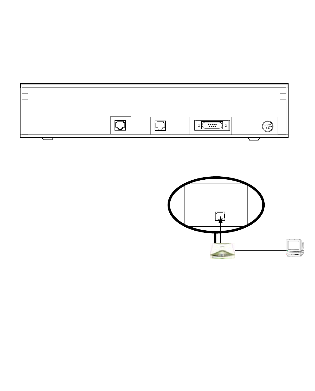
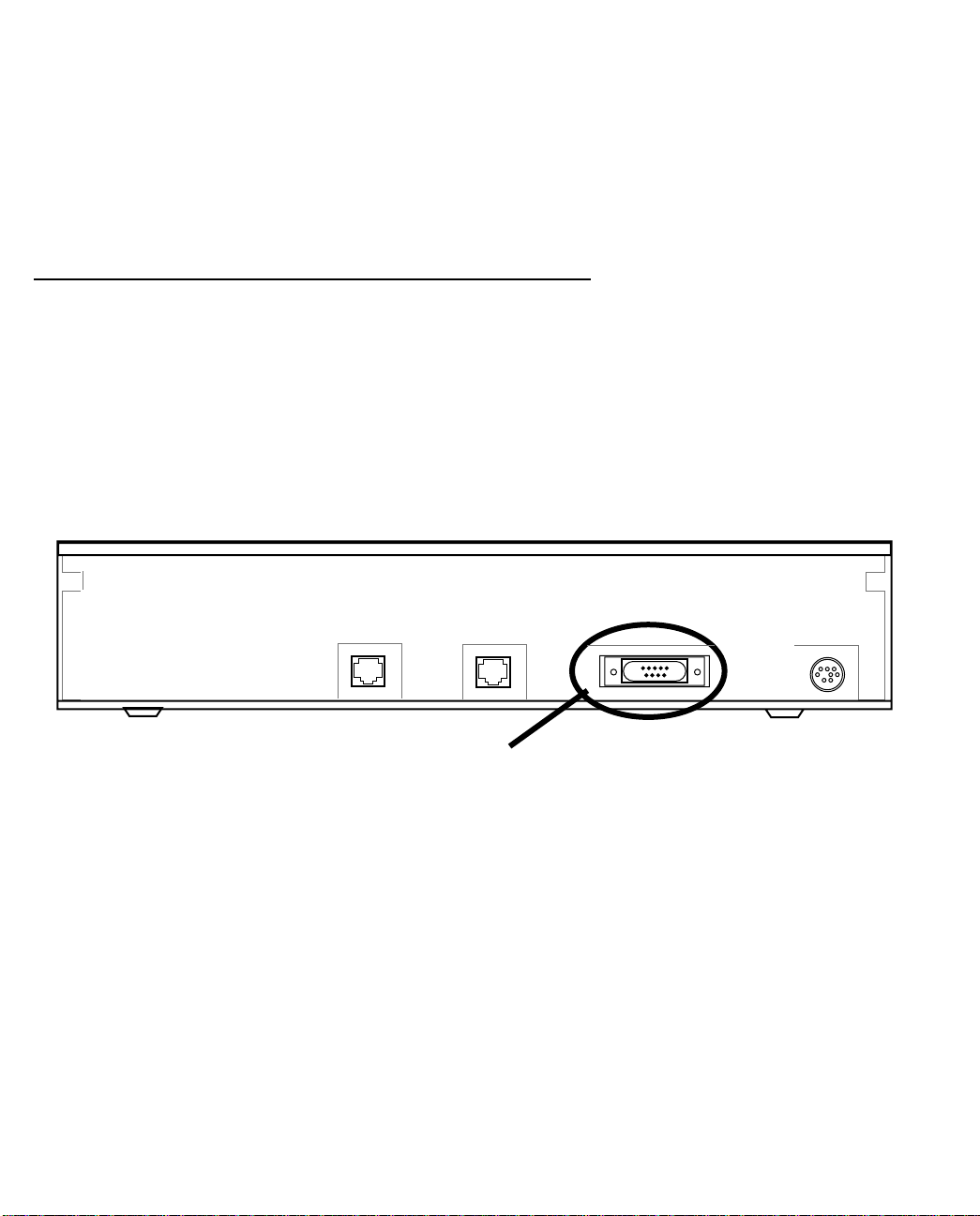
Identify the connectors and attach the cables
Identify the connectors and switches on the back panel and attach the necessary Netopia Router cables.
The figure below displays the back of the Netopia 4541/4542 ADSL Router.
Netopia 4541/4542 back panel
ADSL port
Ethernet port
DSL
10/100
Ethernet
Console Power
Power port
Console port
.
Port Description
Power port A mini-DIN8 power adapter cable connection.
Console port A DB-9 console port for a direct serial connection to the console screens. You
can use this if you are an experienced user. See “Connecting a console cable to
your router” on page 5-3.
DSL port An RJ-48 jack labeled DSL for your ADSL connection.
Ethernet port An RJ-45 10/100Base-T Ethernet jack. Y ou will use this to configure the Netopia
4541/4542. For a new installation, use the Ethernet connection. Alternatively,
you can use the console connection to run console-based management using a
direct serial connection. You can either connect your computer directly the
Ethernet port using a crossover cable, or connect both your computer and the
Netopia 4541/4542 to an existing Ethernet hub on your LAN.
1. Connect the mini-DIN8 connector from the power adapter to the power port, and plug the other end into an
electrical outlet.
2. Connect one end of the Category 5 cable to the DSL port, and the other end to your DSL wall outlet.
Page 13
Making the Physical Connections 2-3
3. Connect the Ethernet cable to the Ethernet port on the router and the other end to your computer.
You should now have: the power adapter plugged in; the Ethernet cable connected between the router and
your computer; and the DSL cable connected between the router and the DSL wall outlet.
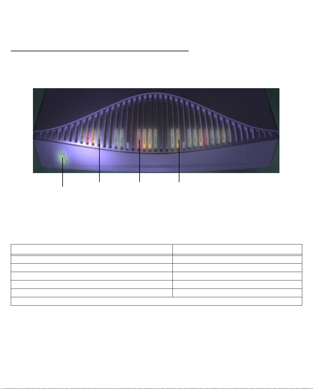
Netopia 4541/4542 ADSL Router status lights
The figure below represents the Netopia 4541/4542 status light (LED) panel.
Netopia 4541/4542 LED front panel
DSL
Power
Error
Ethernet
The following table summarizes the meaning of the various LED states and colors:
When this happens... the LEDs...
The power is on
The Router detects an error
The Ethernet link is established
The WAN has trained
The WAN is training
Note:
The remaining LEDs are not used.
Power
is green.
Error
is red.
Ethernet
DSL
DSL
is green.
is green.
flashes green.
Page 14

2-4 User’s Reference Guide
Page 15

Sharing the Connection 3-1
CCCChhhhaaaapppptttteeeerrrr 33
SSSShhhhaaaarrrriiiinnnngggg tttthhhheeee CCCCoooonnnnnnnneeeeccccttttiiiioooonn
Once you have set up your physical local area network, you will need to configure the TCP/IP stack on each
client workstation connected to your Netopia 4541/4542. This chapter describes how to configure TCP/IP for
both Windows-based and Macintosh computers.
This chapter explains the following topics:
■
“Configuring TCP/IP on Windows-based Computers” on page 3-1
■
“Configuring TCP/IP on Macintosh Computers” on page 3-5
33
nn
Configuring TCP/IP on Windows-based Computers
Configuring TCP/IP on a Windows computer requires the following:
An Ethernet card (also known as a network adapter)
■
The TCP/IP protocol must be “bound” to the adapter or card
■
Page 16
3-2 User’s Reference Guide
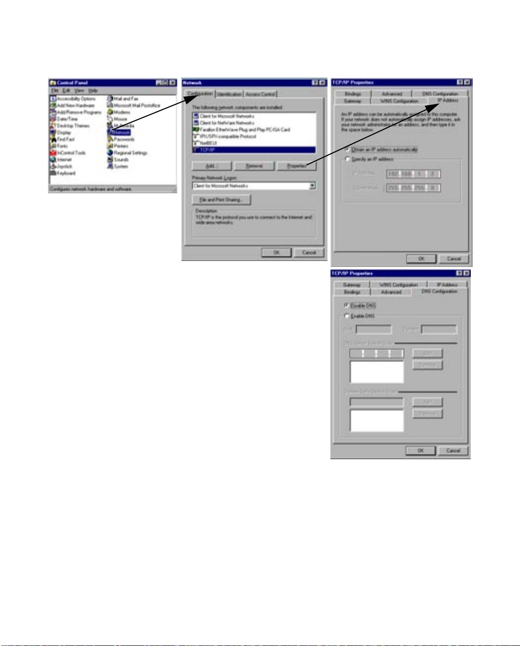
Dynamic configuration (recommended)
To configure your PC for dynamic addressing do the following:
1. Go to the Start
Menu/Settings/Control
Panels and double click
the Network icon. From
the Network components
list, select the
Configuration tab.
2. Select TCP/IP-->Your Network Card. Then select
Properties. In the TCP/IP Properties screen, select the IP
Address tab. Click “Obtain an IP Address automatically”.
3. Click on the DNS Configuration tab. Click Disable DNS.
DNS will be assigned by the router with DHCP.
4. Click OK in this window and the next window. When
prompted, reboot the computer.
Note:
You can also use these instructions to configure other computers on your network to accept IP addresses
served by the Netopia 4541/4542.
Page 17
Sharing the Connection 3-3
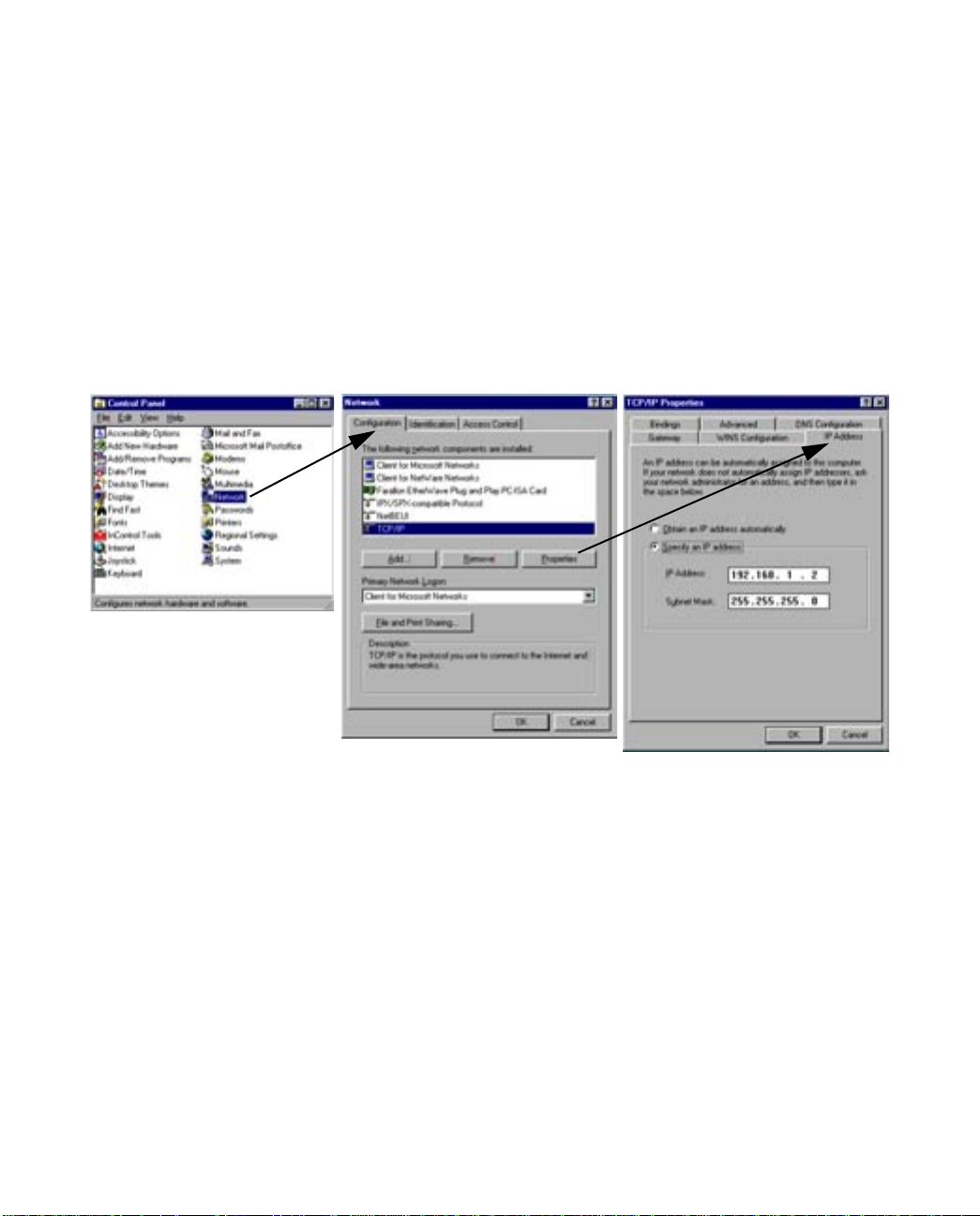
Static configuration (optional)
If you are manually configuring for a fixed or static IP address, perform the following:
1. Go to Start Menu/Settings/Control Panels and double click the Network icon. From the Network
components list, select the Configuration tab.
2. Select TCP/IP-->Your Network Card. Then select Properties. In the TCP/IP Properties screen, select the
IP Address tab. Click “Specify an IP Address.”
Enter the following:
IP Address: 192.168.1.2
Subnet Mask: 255.255.255.0, or for 12-user models 255.255.255.240
This address is an example of one that can be used to configure the router. Your ISP or network
administrator may ask you to use a different IP address and subnet mask.
Page 18
3-4 User’s Reference Guide
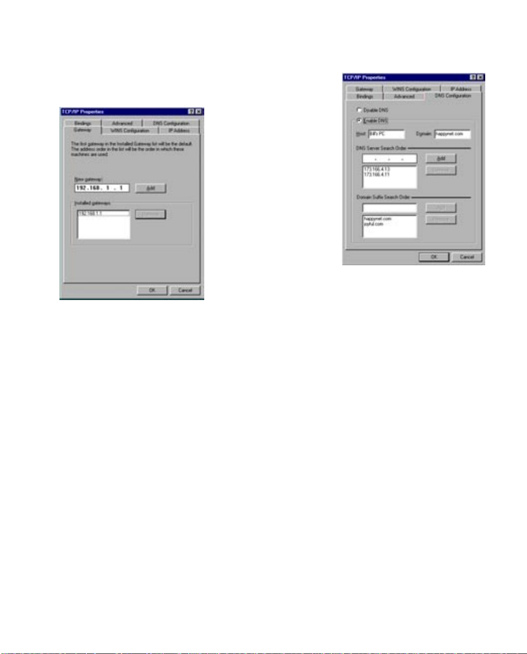
3. Click on the Gateway tab (shown below).
Under “New gateway,” enter
192.168.1.1. Click Add. This is the
Netopia 4541/4542’s pre-assigned IP
address.
4. Click OK in this window and the next window. When prompted, reboot the computer.
Click on the DNS Configuration tab. Click Enable DNS.
Enter the following
information:
Host: Type the name
you want to give to
this computer.
Domain: Type your
domain name. If you
don't have a domain
name, type your ISP's
domain name; for
example,
netopia.com.
DNS Server Search
Order: Type the
primary DNS IP
address given to you
by your ISP. Click
Add. Repeat this process for the secondary DNS.
Domain Suffix Search Order: Enter the same domain
name you entered above.
Note: You can also use these instructions to configure other computers on your network with manual or static
IP addresses. Be sure each computer on your network has its own IP address.
Page 19
Sharing the Connection 3-5
Configuring TCP/IP on Macintosh Computers
The following is a quick guide to configuring TCP/IP for MacOS computers. Configuring TCP/IP in a Macintosh
computer requires the following:
■ You must have either Open Transport or Classic Networking (MacTCP) installed.
Note: If you want to use the Dynamic Host Configuration Protocol (DHCP) server built into your Netopia
4541/4542 to assign IP addresses to your Macintoshes, you must be running Open Transport, standard in
MacOS 8 and optional in earlier system versions. You can have your Netopia 4541/4542 dynamically
assign IP addresses using MacTCP; however, to do so requires that the optional AppleTalk kit be installed
which can only be done after the router is configured.
■ You must have built-in Ethernet or a third-party Ethernet card and its associated drivers installed in your
Macintosh.
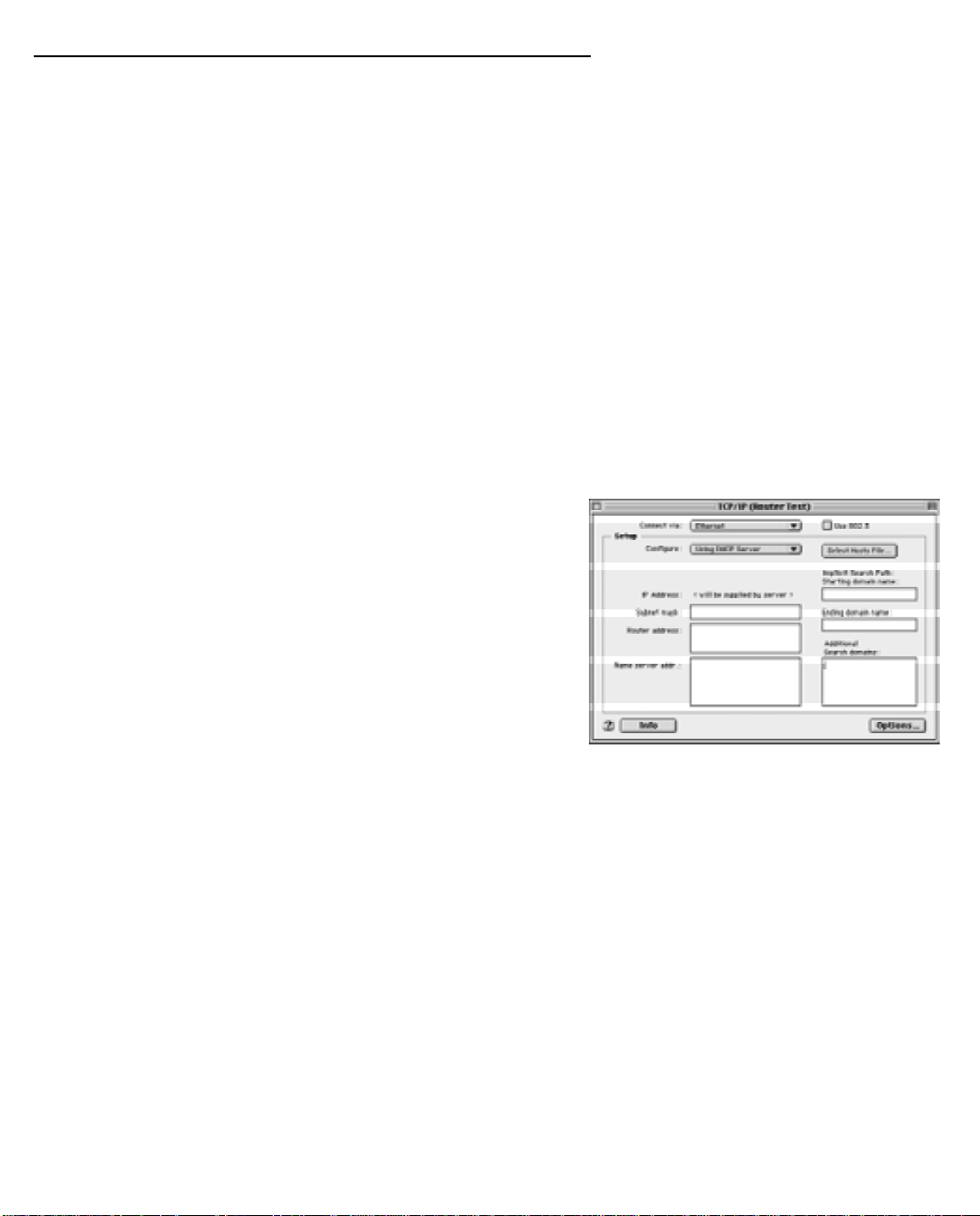
Dynamic configuration (recommended)
The Dynamic Host Configuration Protocol (DHCP), which enables dynamic addressing, is enabled by default in
the router. To configure your Macintosh computer for dynamic addressing do the following:
1. Go to the Apple menu. Select Control Panels and then
TCP/IP.
2. With the TCP/IP window open, go to the Edit menu and
select User Mode. Choose Basic and click OK.
3. In the TCP/IP window, select “Connect via: Ethernet” and
“Configure: Using DHCP Server.”
Note: You can also use these instructions to configure other computers on your network to accept IP addresses
served by the Netopia 4541/4542.
Page 20
3-6 User’s Reference Guide
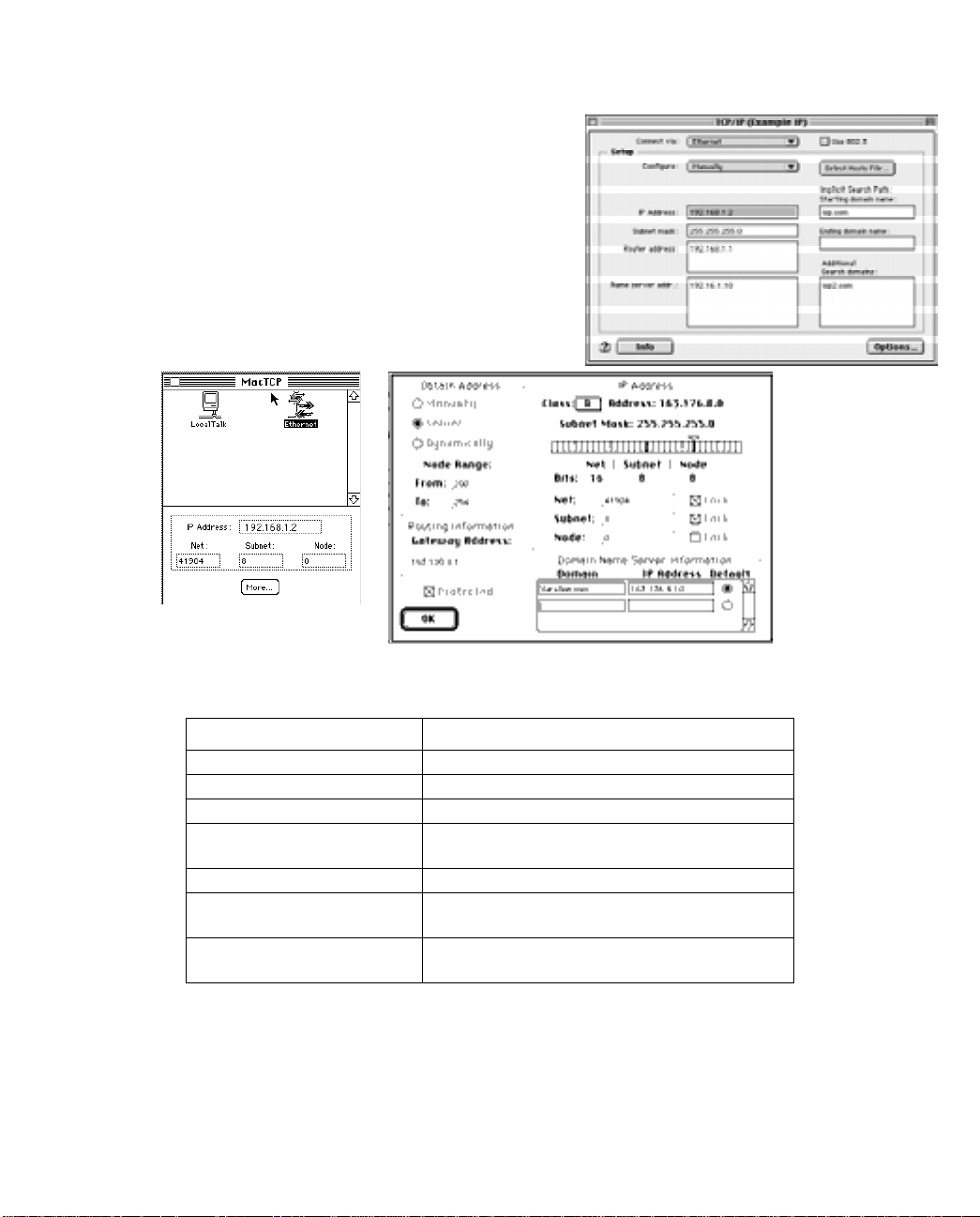
Static configuration (optional)
If you are manually configuring for a fixed or static IP address,
perform the following:
1. Go to the Apple menu. Select Control Panels and then
TCP/IP or MacTCP.
2. With the TCP/IP window open, go to the Edit menu and
select User Mode. Choose Advanced and click OK.
Or, in the MacTCP window, select Ethernet and click the
More button.
3. In the TCP/IP window or in the MacTCP/More window, select or type information into the fields as shown in
the following table.
Option: Select/Type:
Connect via: Ethernet
Configure: Manually
IP Address: 192.168.1.2
Subnet mask: 255.255.255.0, or for 12-user models
255.255.255.240
Router or Gateway address: 192.168.1.1
Name server address: Enter the primary and secondary name server
addresses given to you by your ISP
Implicit Search Path:
Starting domain name:
Enter your domain name; if you do not have a
domain name, enter the domain name of your ISP
4. Close the TCP/IP or MacTCP control panel and save the settings.
5. If you are using MacTCP, you must restart the computer. If you are using Open Transport, you do not need
to restart.
Note: You can also use these instructions to configure other computers on your network to accept IP addresses
served by the Netopia 4541/4542.
Page 21

Sharing the Connection 3-7
Note: You can also use these instructions to configure other computers on your network with manual or static
IP addresses. Be sure each computer on your network has its own IP address.
More information about configuring your Macintosh computer for TCP/IP connectivity through a Netopia
4541/4542 can be found in T echnote NIR_026, “Open T ransport and Netopia Routers,” located on the Netopia
Web site.
Page 22

3-8 User’s Reference Guide
Page 23
Connecting to Your Local Area Network 4-1
CCCChhhhaaaapppptttteeeerrrr 44
CCCCoooonnnnnnnneeeeccccttttiiiinnnngggg ttttoooo YYYYoooouuuurrrr LLLLooooccccaaaallll AAAArrrreeeeaaaa NNNNeeeettttwwwwoooorrrrkk
This chapter describes how to physically connect the Netopia 4541/4542 to your local area network (LAN).
Before you proceed, make sure the Netopia 4541/4542 is properly configured. You can customize the router’s
configuration for your particular LAN requirements using console-based management (see “Console-Based
Management” on page 5-1).
This section covers the following topics:
■ “Readying computers on your local network” on page 4-1
■ “Connecting to an Ethernet network” on page 4-2
44
kk
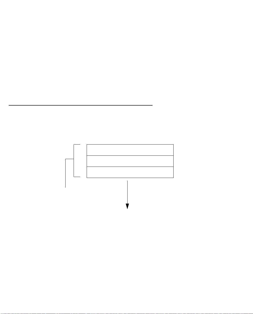
Readying computers on your local network
PC and Macintosh computers must have certain components installed before they can communicate through
the Netopia 4541/4542. The following illustration shows the minimal requirements for a typical PC or
Macintosh computer.
Application software
TCP/IP stack
Ethernet Driver
Your PC
or Macintosh
computer
To the Netopia
Application software: This is the software you use to send e-mail, browse the World Wide Web, read
newsgroups, etc. These applications may require some configuration. Examples include the Eudora e-mail client
and the Web browsers Microsoft Internet Explorer and Netscape Navigator.
TCP/IP stack: This is the software that lets your PC or Macintosh computer communicate using Internet
protocols. TCP/IP stacks must be configured with some of the same information you used to configure the
Netopia 4541/4542. There are a number of TCP/IP stacks available for PC computers. Windows 95 includes a
built-in TCP/IP stack. Macintosh computers use either MacTCP or Open Transport. See “Configuring TCP/IP on
Windows-based Computers” on page 3-1. Macintosh computers use either MacTCP or Open Transport. See
“Configuring TCP/IP on Macintosh Computers” on page 3-5.
Ethernet: Ethernet hardware and software drivers enable your PC or Macintosh computer to communicate on
the LAN.
Page 24
4-2 User’s Reference Guide
Once the Netopia 4541/4542 is properly configured and connected to your LAN, PC and Macintosh computers
that have their required components in place will be able to connect to the Internet or other remote IP networks.
Connecting to an Ethernet network
The Netopia 4541/4542 supports Ethernet connections through its Ethernet port. You can connect a standard
10 or 100Base-T Ethernet network to the Netopia 4541/4542 using its Ethernet port.
Netopia 4541/4542 back panel
DSL
The Netopia 4541/4542 in a 10Base-T network
To connect your 10Base-T network to the Netopia
4541/4542 through the Ethernet port, use a
10Base-T cable with RJ-45 connectors.
If you have more than one device to connect, you
can attach additional devices using a cross-over
cable (not provided) or you can connect through a
switch or repeater.
10/100
Ethernet
Console Power
10/100
Ethernet
Page 25

Console-Based Management 5-1
CCCChhhhaaaapppptttteeeerrrr 55
CCCCoooonnnnssssoooolllleeee----BBBBaaaasssseeeedddd MMMMaaaannnnaaaaggggeeeemmmmeeeennnntt
Console-based management is a menu-driven interface for the capabilities built into the Netopia 4541/4542.
Console-based management provides access to a wide variety of features that the router supports. You can
customize these features for your individual setup. This chapter describes how to access the console-based
management screens.
This section covers the following topics:
■ “Connecting through a Telnet session” on page 5-2
■ “Connecting a console cable to your router” on page 5-3
■ “Navigating through the console screens” on page 5-4
Console-based management screens contain seven entry points to the Netopia 4541/4542 configuration and
monitoring features. The entry points are displayed in the Main Menu shown below:
55
tt
Netopia 4541
Easy Setup...
WAN Configuration...
System Configuration...
Utilities & Diagnostics...
Statistics & Logs...
Quick Menus...
Quick View...
Return/Enter goes to Easy Setup -- minimal configuration.
You always start from this main screen.
■ The Easy Setup menus display and permit changing the values contained in the default connection profile.
You can use Easy Setup to initially configure the router directly through a console session.
Easy Setup menus contain up to five descendant screens for viewing or altering these values. The number
of screens depends on whether you have optional features installed.
■ The WAN Configuration menu displays and permits changing your connection profile(s) and default profile,
creating or deleting additional connection profiles, and configuring or reconfiguring the manner in which you
Page 26

5-2 User’s Reference Guide
may be using the router to connect to more than one service provider or remote site.
■ The System Configuration menus display and permit changing:
■ IP setup. See “IP Setup” on page 8-1.
■ Filter sets (firewalls). See “Security” on page 11-1.
■ IP address serving. See “IP Address Serving” on page 8-10.
■ Date and time. See “Date and time” on page 7-16.
■ Console configuration. See “Connecting a console cable to your router” on page 5-3.
■ SNMP (Simple Network Management Protocol). See “SNMP” on page 12-9.
■ Security. See “Security” on page 11-1.
■ Upgrade feature set. See “Upgrade feature set” on page 7-18.
■ The Utilities & Diagnostics menus provide a selection of seven tools for monitoring and diagnosing the
router's behavior, as well as for updating the firmware and rebooting the system. See “Utilities and
Diagnostics” on page 13-1 for detailed information.
■ The Statistics & Logs menus display nine sets of tables and device logs that show information about your
router, your network, and their history. See “Statistics & Logs” on page 12-4 for detailed information.
■ The Quick Menus screen is a shortcut entry point to 22 of the most commonly used configuration menus
that are accessed through the other menu entry points.
■ The Quick View menu displays at a glance current real-time operating information about your router. See
“Quick View status overview” on page 12-1 for detailed information.
Connecting through a Telnet session
Features of the Netopia 4541/4542 can be configured through the console screens.
Before you can access the console screens through Telnet, you must have:
■ A network connection locally to the router or IP access to the router.
Note: Alternatively, you can have a direct serial console cable connection using the provided console cable
for your platform (PC or Macintosh) and the Console port on the back of the router. For more information on
attaching the console cable, see “Connecting a console cable to your router” on page 5-3.
■ Telnet software installed on the computer you will use to configure the router
Page 27
Console-Based Management 5-3
Configuring Telnet software
If you are configuring your router using a Telnet session, your computer must be running a Telnet software
program.
■ If you connect a PC with Microsoft Windows, you can use a Windows Telnet application or simply run Telnet
from the Start menu.
■ If you connect a Macintosh computer, you can use the NCSA Telnet program supplied on the Netopia
4541/4542 CD. You install NCSA Telnet by simply dragging the application from the CD to your hard disk.
Connecting a console cable to your router
You can perform all of the system configuration activities for your Netopia 4541/4542 through a local serial
console connection using terminal emulation software, such as HyperTerminal provided with Windows 95, 98,
2000, or NT on the PC, or ZTerm, included on the Netopia CD, for Macintosh computers.
The Netopia 4541/4542 back panel has a connector labeled “Console” for attaching the Router to either a PC
or Macintosh computer via the serial port on the computer. (On a Macintosh computer, the serial port is called
the Modem port or Printer port.) This connection lets you use the computer to configure and monitor the
Netopia 4541/4542 via the console screens.
DSL
10/100
Ethernet
Console Power
Console connection port
DB-9 (male)
To connect the Netopia 4541/4542 to your computer for serial console communication, use a console cable
appropriate to your platform:
■ A DB-9 connector end attaches to a PC.
■ A mini-DIN8 connector end attaches to a Macintosh computer depending on your computer’s serial bus
type. Since Macintosh computers have different serial bus connectors, you will need a mini-DIN8-to-DB-9
adapter. These are available from a variety of third-party manufacturers.
■ A DB-9 end of the Console cable attaches to the Netopia 4541/4542’s Console port.
■ If you connect a PC with Microsoft Windows 95, 98, 2000, or NT, you can use the HyperTerminal
application bundled with the operating system.
■ If you connect a Macintosh computer, you can use the ZTerm terminal emulation program on the supplied
Netopia 4541/4542 CD.
Page 28

5-4 User’s Reference Guide
Launch your terminal emulation software and configure the communications software for the values shown in
the table below. These are the default communication parameters that the Netopia 4541/4542 uses.
Parameter Suggested Value
Terminal type PC: ANSI-BBS
Mac: ANSI, VT-100, or VT-200
Data bits 8
Parity None
Stop bits 1
Speed 9600 - 57600 bits per second
Flow Control None
Note: The router firmware contains an autobaud detection feature. If you are at any
screen on the serial console, you can change your baud rate and press Return
(HyperTerminal for the PC requires a disconnect). The new baud rate is displayed at
the bottom of the screen.
Navigating through the console screens
Use your keyboard to navigate the Netopia 4541/4542’s configuration screens, enter and edit information, and
make choices. The following table lists the keys to use to navigate through the console screens.
To... Use These Keys...
Move through selectable items in a screen or pop-up menu Up, Down, Left, and Right Arrow
Set a change to a selected item or open a pop-up menu of
options for a selected item like entering an upgrade key
Change a toggle value (Yes/No, On/Off) Tab
Restore an entry or toggle value to its previous value Esc
Move one item up Up arrow or Control + K
Move one item down Down arrow or Control + O
Display a dump of the device event log Control + E
Display a dump of the WAN event log Control + F
Refresh the screen Control + L
Return or Enter
Page 29

Easy Setup 6-1
CCCChhhhaaaapppptttteeeerrrr 66
EEEEaaaassssyyyy SSSSeeeettttuuuupp
This chapter describes how to use the Easy Setup console screens on your Netopia 4541/4542. After
completing the Easy Setup console screens, your router will be ready to connect to the Internet or another
remote site.
66
pp
Easy Setup console screens
Using four Easy Setup console screens, you can:
■ Modify a connection profile for your router for the connection to your ISP or remote location
■ Set up IP addresses and IP address serving
■ Password–protect configuration access to your Netopia 4541/4542
Accessing the Easy Setup console screens
To access the console screens, Telnet to the Netopia Router over your Ethernet network or physically connect
with a serial console cable and access the Netopia Router with a terminal emulation program. See “Connecting
through a Telnet session” on page 5-2 or “Connecting a console cable to your router” on page 5-3.
Note: Before continuing, make sure you have the information that your ISP or network administrator has given
you for configuring the Netopia Router.
The Netopia Router’s first console screen, Main Menu, appears in the terminal emulation window of the
attached PC or Macintosh computer when:
■ The Netopia Router is turned on
■ The computer is connected to the Netopia Router
■ Telnet or the terminal emulation software is running and configured correctly
A screen similar to the following Main Menu appears:
Page 30

6-2 User’s Reference Guide
Netopia Router
Easy Setup...
WAN Configuration...
System Configuration...
Utilities & Diagnostics...
Statistics & Logs...
Quick Menus...
Quick View...
If you do not see the Main Menu, verify that:
■ If you are using a serial connection, that your serial port speed is the same as the Netopia 4541/4542’s
default 9600 baud, for first use.
■ The computer used to view the console screen has its serial port connected to the Netopia 4541/4542’s
Console port or an Ethernet connection to one of its Ethernet ports. See “Connecting a console cable to
your router” on page 5-3 or “Connecting through a Telnet session” on page 5-2.
■ Telnet or the terminal emulation software is configured for the recommended values.
■ If you are connecting via the Console port, your computer’s serial port is not being used by another device,
such as an internal modem, or an application. Turn off all other programs (other than your terminal
emulation program) that may be interfering with your access to the port.
■ You have entered the correct password, if necessary. Your Netopia 4541/4542’s console access may be
password protected from a previous configuration. See your system administrator to obtain the password.
See Appendix A, “Troubleshooting,” for more suggestions.
Quick Easy Setup connection path
If your ISP assigns your Router a Static IP address, do the following:
1. Open a Telnet session to 192.168.1.1 to bring up the Main Menu.
If you don't know how to do this, see “Connecting through a Telnet session” on page 5-2.
Alternatively, you can connect the console cable and open a direct serial console connection, using a
terminal emulator program. See “Connecting a console cable to your router” on page 5-3.
Page 31

Easy Setup 6-3
The Main Menu appears.
Netopia Router
Easy Setup...
WAN Configuration...
System Configuration...
Utilities & Diagnostics...
Statistics & Logs...
Quick Menus...
Quick View...
2. Select the first item on the Main Menu list, Easy Setup. Press Return to bring up the ADSL Line
Configuration menu screen.
DSL Line Configuration
ADSL Line Configuration
Circuit Type... Multimode
Data Link Encapsulation... RFC1483
RFC1483 Mode... Bridged 1483
PPP over Ethernet (PPPoE): Off
Data Circuit VPI (0-255): 8
Data Circuit VCI (0-65535): 35
PREVIOUS SCREEN NEXT SCREEN
1. Select Circuit Type and, from the pop-up menu, choose the type of circuit to which you will be connecting:
Multimode, T1.413, G.dmt, G.lite, or ADI.
2. Select Data Link Encapsulation and from the pop-up menu choose either RFC1483 (the default) or PPP.
■ If you selected RFC1483, the next pop-up menu RFC1483 Mode offers the choice of Bridged 1483 or
Page 32

6-4 User’s Reference Guide
Routed 1483. If you select Bridged 1483, a new option PPP over Ethernet (PPPoE) appears. You can
then toggle PPPoE On or Off. Choosing Routed 1483 hides the PPPoE option.
■ If you selected PPP, the next pop-up menu PPP Mode offers the choice of VC Multiplexed or LLC SNAP.
3. The next two fields, Data Circuit VPI and Data Circuit VCI are editable. Enter the Virtual Path Identifier and
Virtual Channel Identifier values that your provider specifies.
4. Press the Down arrow key until you reach NEXT SCREEN. Press Return to bring up the next screen.
Easy Setup Profile
The Easy Setup Profile screen is where you configure the parameters that control the Netopia 4541/4542’s
connection to a specific remote destination, usually your ISP or a corporate site.
On a Netopia 4541/4542 you can add up to 15 more connection profiles, for a total of 16, although you can
only use one at a time, unless you are using Virtual Private Networks (VPNs).
Connection Profile 1: Easy Setup Profile
Connection Profile Name: Easy Setup Profile
Address Translation Enabled: Yes
IP Addressing... Numbered
Local WAN IP Address: 0.0.0.0
Local WAN IP Mask: 0.0.0.0
Remote IP Address: 0.0.0.0
Remote IP Mask: 0.0.0.0
PPP Authentication... None
PREVIOUS SCREEN NEXT SCREEN
Note: The appearance of this screen varies, depending on the settings in the previous screen.
1. To enable address translation, toggle Address Translation Enabled to Yes (the default). For more
information on Network Address Translation, see Chapter 9, “Multiple Network Address Translation.”
2. From the IP Addressing menu item, choose between Unnumbered and Numbered addressing. Numbered is
the default for ADSL. It assigns a unique IP address to the ADSL WAN interface, as required by most ISPs’
routers. Unnumbered may be used for simpler configurations such as point-to-point applications.
Page 33

Easy Setup 6-5
If you selected Numbered, the following fields appear.
■ Select the editable field labeled Local WAN IP Address.
The default address is 0.0.0.0, which allows for dynamic addressing, when your ISP assigns an address
each time you connect. However, you can enter another specific address if you want to use static
addressing. In that case, enter the local WAN address your ISP gave you. Press Return.
■ Select the editable field labeled Local WAN IP Mask. Enter the mask address your ISP gave you. Press
Return.
If you selected Unnumbered, the following fields appear.
■ Select the editable field labeled Remote IP Address and enter the remote IP address. Press Return.
■ Select the editable field labeled Remote IP Mask and enter the remote mask address. Press Return.
3. If you selected PPP data link encapsulation in the DSL Line Configuration screen, a PPP Authentication
menu item appears. The authentication protocol and user name/password combinations you enter must
be assigned or agreed to in advance between you and your ISP. Select PPP Authentication and press
Return.
From the pop-up menu that appears, select the authentication method your ISP uses: PAP (Password
Authentication Protocol), CHAP (Challenge Handshake Authentication Protocol), or None.
■ PAP is the most common, and requires you to enter a User Name and Password in the next two fields.
■ CHAP requires you to enter a Host Name and Secret in the next two fields.
4. Press the Down arrow key until you reach NEXT SCREEN. Press Return to bring up the next screen.
IP Easy Setup
The IP Easy Setup screen is where you enter information about your Netopia Router’s:
■ Ethernet IP address
■ Ethernet Subnet mask
■ Domain Name
■ Domain Name Server IP address
■ Default gateway IP address
Consult with your network administrator to obtain the information you will need. For more information about
setting up IP, see “IP Setup” on page 8-2.
Page 34

6-6 User’s Reference Guide
IP Easy Setup
Ethernet IP Address: 192.168.1.1
Ethernet Subnet Mask: 255.255.255.0
Domain Name: isp.net
Primary Domain Name Server: 209.3.224.21
Secondary Domain Name Server: 209.3.224.20
Default IP Gateway: 127.0.0.2
IP Address Serving: On
Number of Client IP Addresses: 100
1st Client Address: 192.168.1.100
PREVIOUS SCREEN NEXT SCREEN
Enter an IP address in decimal and dot form (xxx.xxx.xxx.xxx).
Set up the basic IP & IPX attributes of your Netopia in this screen.
1. Select Ethernet IP Address and enter the first IP address from the IP address range your ISP has given
you. This will be the Netopia Router’s IP address.
The Ethernet IP Address defaults to an address (192.168.1.1) within a range reserved by the Internet
address administration authority for use within private networks.
Because this is a private network address, it should never be directly connected to the Internet. Using NAT
for all your connection profiles will ensure this restriction. See Chapter 9, “Multiple Network Address
Translation,” for more information.
2. Select Ethernet Subnet Mask and enter the subnet mask your ISP has given you. The Ethernet Subnet
Mask defaults to a standard class mask derived from the class of the Ethernet IP address you entered in
the previous step.
3. Press the Down arrow key until the editable field labeled Domain Name is highlighted.
4. Type the Domain Name your ISP gave you. Press Return. The next field Primary Domain Name Server will
be highlighted.
5. Type the Primary Domain Name Server address your ISP gave you. Press Return. A new field Secondary
Domain Name Server will appear. If your ISP gave you a secondary domain name server address, enter it
here. Press Return until the next field Default IP Gateway is highlighted.
6. If you do not enter a Default IP Gateway value, the router defaults to the remote IP address you entered in
the Easy Setup connection profile. If the Netopia Router does not recognize the destination of any IP traffic,
it forwards that traffic to this gateway.
Do not confuse the remote IP address and the Default IP Gateway’s address with the block of local IP
addresses you receive from your ISP. You use the local IP addresses for the Netopia 4541/4542’s
Ethernet port and for IP clients on your local network. The remote IP address and the default gateway’s IP
address should point to your ISP’s router.
Page 35

Easy Setup 6-7
7. Toggle IP Address Serving to On or Off, depending on whether you want the device’s IP address server to
supply dynamic IP addresses to your client workstations. Normally, you would accept the default On so that
workstations on your LAN can have IP addresses assigned dynamically from the router.
8. The IP address server will provide 100 IP addresses automatically to workstations on your LAN. You only
need to change the Number of Client IP Addresses if you have some other IP addressing scheme.
9. By default, the 1st Client Address is 192.168.1.100, based on the device’s default IP address of
192.168.1.1. You only need to change this if you have some other IP addressing scheme.
10. Press the Down arrow key until you reach NEXT SCREEN. Press Return.
Easy Setup Security Configuration
The Easy Setup Security Configuration screen lets you password-protect your Netopia 4541/4542. Input your
Write Access Name and Write Access Password with names or numbers totaling up to eleven digits.
If you password protect the console screens, you will be prompted to enter the name and password you have
specified every time you log in to the console screens. Do not forget your name and password. If you do, you
will be unable to access any of the configuration screens.
Additional security features are available. See “Security” on page 11-1.
Easy Setup Security Configuration
It is strongly suggested that you password-protect configuration access to your
Netopia. By entering a Name and Password pair here, access via serial,
Telnet, and SNMP will be password-protected.
Be sure to remember what you have typed here, because you will be prompted for
it each time you configure this Netopia.
Write Access Name:
Write Access Password:
PREVIOUS SCREEN TO MAIN MENU RESTART DEVICE
Configure a Configuration Access Name and Password here.
The final step in configuring the Easy Setup console screens is to restart the Netopia 4541/4542, so that the
configuration settings take effect.
1. Select RESTART DEVICE. A prompt asks you to confirm your choice.
2. Select CONTINUE to restart the Netopia Router and have your selections take effect.
Note: You can also restart the system at any time by using the Restart System utility (see “Restarting the
system” on page 13-12) or by turning the Netopia Router off and on with the power switch.
Page 36

6-8 User’s Reference Guide
The Router will restart and your configuration settings will be activated. You can then Exit or Quit your Telnet
application.
Easy Setup is now complete.
Page 37

WAN and System Configuration 7-1
CCCChhhhaaaapppptttteeeerrrr 77
WWWWAAAANNNN aaaannnndddd SSSSyyyysssstttteeeemmmm CCCCoooonnnnffffiiiigggguuuurrrraaaattttiiiioooonn
This chapter describes how to use the console-based management screens to access and configure advanced
features of your Netopia 4541/4542 ADSL Router. You can customize these features for your individual setup.
These menus provide a powerful method for experienced users to set up their router’s connection profiles and
system configuration.
This section covers the following topics:
■ “WAN configuration” on page 7-1
■ “Creating a new Connection Profile” on page 7-4
■ “The default profile” on page 7-7
■ “Scheduled connections” on page 7-8
■ “System configuration screens” on page 7-13
■ “Navigating through the system configuration screens” on page 7-14
■ “System configuration features” on page 7-15
77
nn
WAN configuration
To configure your Wide Area Network (WAN) connection, navigate to the WAN Configuration screen from the Main
Menu and select WAN (Wide Area Network) Setup.
Main
Menu
The ADSL Line Configuration screen appears.
WAN
Configuration
WAN
Setup
Page 38

7-2 User’s Reference Guide
ADSL Line Configuration
Circuit Type... Multimode
Signaling Mode... FDM
Trellis Coding Enabled: On
Cell Format... Scrambled
Unused Cell Format... Idle
Data Link Encapsulation... RFC1483
RFC1483 Mode... Bridged 1483
PPP over Ethernet (PPPoE): Off
Display/Change Circuit...
Add Circuit...
Delete Circuit...
1. Select Circuit Type and from the pop-up menu choose the type of circuit to which you will be connecting.
■ Model 4541 offers Multimode, T1.413, G.dmt, G.lite, or ADI.
■ Model 4542 offers Multimode, ADI ETDI, ITU Standard, UR2, ADI Legacy, TI Legacy and Alcatel ETSI.
2. Select Signaling Mode and choose Echo Cancellation or FDM (the default).
3. If you selected Multimode or G.lite as the Circuit Type, the Trellis Coding Enabled field appears. Toggle it
to On (the default) or Off.
4. Select whether the Cell Format is Unscrambled (the default) or Scrambled, and whether the Unused Cell
Format is Empty or Idle (the default).
5. Select Data Link Encapsulation and press Return. The pop-up menu will offer you the choice of PPP or
RFC1483.
■ If you selected PPP as your data link encapsulation method, the PPP Mode pop-up menu offers the
choice of VC Multiplexed (the default) or LLC SNAP.
■ If you selected RFC1483 your data link encapsulation method, two additional options display: an
RFC1483 Mode pop-up menu offers the choice of Bridged 1483 or Routed 1483. Bridged 1483 permits use of PPP over Ethernet (PPPoE) and is the default. You can then toggle PPPoE On or Off.
Choosing Routed 1483 hides the PPPoE option.
6. To add a circuit, select Add Circuit and press Return. The Add Circuit screen appears.
Page 39

WAN and System Configuration 7-3
Add Circuit
Circuit Name: Circuit 2
Circuit Enabled: Yes
Circuit VPI (0-255): 0
Circuit VCI (0-65535): 0
Use Connection Profile... Default Profile
Use Default Profile for Circuit
ADD Circuit NOW CANCEL
■ Enter a name for the circuit in the Circuit Name field.
■ Toggle Circuit Enabled to Yes.
■ Enter the Virtual Path Identifier and the Virtual Channel Identifier in the Circuit VPI and Circuit VCI
fields, respectively.
■ Then, select a Connection Profile for the Circuit. To use the Default Profile, select Use Default Profile
for Circuit and press Return. For other options, select a profile from the Use Connection Profile
pop-up menu.
■ Select ADD Circuit NOW and press Return.
7. To display or change a circuit, select Display/Change Circuit, select a cicuit from the pop-up menu, and
press Return. The fields are the same as those in the Add Circuit screen.
8. To delete a circuit, select Delete Circuit, select a cicuit from the pop-up menu, and press Return. In the
confirmation window, select CONTINUE and press Return.
9. Press Escape to return to the WAN Setup menu.
Page 40

7-4 User’s Reference Guide
Creating a new Connection Profile
For a Netopia 4541/4542, connection profiles are useful for configuring the connection and authentication
settings for negotiating a PPP connection on the ADSL link. If you are using the PPP data link encapsulation
method, you can store your authentication information in the connection profile so that your user name and
password (or host name and secret) are transmitted when you attempt to connect.
Connection profiles define the networking protocols necessary for the router to make a remote connection. A
connection profile is like an address book entry describing how the router is to get to a remote site, or how to
recognize and authenticate a connection. To create a new connection profile, you navigate to the WAN
Configuration screen from the Main Menu, and select Add Connection Profile.
Main
Menu
The Add Connection Profile screen appears.
Add Connection Profile
Profile Name: Profile 1
Profile Enabled: Yes
Data Link Encapsulation... PPP
Data Link Options...
IP Profile Parameters...
COMMIT CANCEL
Configure a new Conn. Profile. Finished? ADD or CANCEL to exit.
WAN
Configuration
Add Connection
Profile
On a Netopia 4541/4542 you can add up to 15 more connection profiles, for a total of 16, but you can only use
one at a time, unless you are using VPNs.
1. Select Profile Name and enter a name for this connection profile. It can be any name you wish. For
example: the name of your ISP.
2. Toggle Profile Enabled to Yes or No. The default is Yes.
Page 41

WAN and System Configuration 7-5
3. Select Data Link Encapsulation and press Return. The pop-up menu offers the possible data link
encapsulation methods for connection profiles used for a variety of purposes: PPP, RFC1483, ATMP, PPTP,
or IPsec. If you select any data link encapsulation method other than RFC1483, a Data Link Options menu
item is displayed; if you select RFC1483, Data Link Options is hidden.
4. If you chose any data link encapsulation method other than RFC1483, select Datalink Options and press
Return.
■ If you selected ATMP, PPTP, or IPSec, see Chapter 10, “Virtual Private Networks (VPNs).”
■ If you selected PPP, the Datalink (PPP/MP) Options screen appears.
Datalink (PPP/MP) Options
Data Compression... Standard LZS
Send Authentication... PAP
Send User Name:
Send Password:
Receive User Name:
Receive Password:
Maximum Packet Size: 1500
In this Screen you will configure the PPP/MP specific connection params.
Select Data Compression and press Return. The pop-up menu offers the choices of None, Ascend LZS, or
Standard LZS. Unless you are otherwise specifically directed, you can accept the default.
Select Send Authentication and press Return.
From the pop-up menu that appears, select the authentication method your ISP uses, if any: PAP (Password
Authentication Protocol), CHAP (Challenge Handshake Authentication Protocol), or None.
■ PAP is the most common, and requires you to enter a User Name and Password in the next two fields.
■ CHAP requires you to enter a Host Name and Secret in the next two fields.
You can specify user name and password for both outgoing and incoming connections. The Send User
Name/Password parameters are used to specify your identity when connecting to a remote location. The
Receive User Name/Password parameters are used when the ISP router requires authentication; this is
not commonly required.
5. You can edit the Maximum Packet Size field, if you want packets limited to a lower value than 1500.
Return to the Add Connection Profile screen by pressing Escape.
6. Select IP Profile Parameters and press Return. The IP Profile Parameters screen appears.
Page 42

7-6 User’s Reference Guide
IP Profile Parameters
Address Translation Enabled: Yes
IP Addressing... Numbered
NAT Map List... Easy-PAT List
NAT Server List... Easy-Servers
Local WAN IP Address: 0.0.0.0
Local WAN IP Mask: 0.0.0.0
Filter Set...
Remove Filter Set
RIP Profile Options...
7. Toggle or enter any IP Parameters you require and return to the Add Connection Profile screen by pressing
Escape. For more information, see “IP Setup” on page 8-2.
8. Select COMMIT and press Return. Your new Connection Profile will be added.
If you want to view the Connection Profiles in your device, return to the WAN Configuration screen, and
select Display/Change Connection Profile. The list of Connection Profiles is displayed in a scrolling pop-up
screen.
WAN Configuration
+-Profile Name---------------------IP Address------+
+--------------------------------------------------+
| Easy Setup Profile 255.225.255.255 |
| Profile 1 0.0.0.0 |
| |
| |
| |
| |
| |
| |
| |
| |
| |
| |
| |
| |
| |
| |
+--------------------------------------------------+
Page 43

WAN and System Configuration 7-7
The default profile
If you are using RFC1483 datalink encapsulation, the Default Profile screen controls whether or not the ADSL
link will come up without an explicitly configured connection profile. (PPP datalink encapsulation does not
support a default profile, and the corresponding menu item is unavailable.) See “Connection Profiles” on
page 8-25 for more information.
You access the Default Profile screen from the Main Menu by selecting WAN Configuration and then selecting
Default Profile.
Main
Menu
The Default Profile screen appears.
WAN Default Profile
Must Match a Defined Profile: No
IP Parameters...
WAN
Configuration
WAN
Default Profile
■ You can set Must Match a Defined Profile item to Yes or No (the default). This item controls whether or
not the ADSL link will come up without an explicitly configured connection profile. If your ISP is serving you
a dynamic IP Address, you need not explicitly configure a connection profile, and the default behavior of the
router will be to connect automatically once it is powered on.
Page 44

7-8 User’s Reference Guide
IP parameters (default profile) screen
If you are using RFC1483 datalink encapsulation, the IP Parameters (Default Profile) screen allows you to
configure various IP parameters for ADSL connections established without an explicitly configured connection
profile:
IP Parameters (Default Profile)
Address Translation Enabled: No
Filter Set (Firewall)...
Remove Filter Set
Receive RIP: Both
Transmit RIP: Off
Return/Enter accepts * Tab toggles * ESC cancels.
For an ADSL link, Network Address Translation (NA T) is disabled by default in the Default Profile. You can enable
it by toggling to Yes. For details on setting up IP Parameters see “IP Setup” on page 8-2.
Scheduled connections
Scheduled connections are useful for PPPoE, PPTP, and ATMP connection profiles.
To go to the Scheduled Connections screen, select Scheduled Connections in the WAN Configuration screen.
Main
Menu
WAN
Configuration
Scheduled
Connections
Page 45

WAN and System Configuration 7-9
Scheduled Connections
Display/Change Scheduled Connection...
Add Scheduled Connection...
Delete Scheduled Connection...
Navigate from here to add/modify/change/delete Scheduled Connections.
Viewing scheduled connections
To display a table of scheduled connections, select Display/Change Scheduled Connection in the Scheduled
Connections screen. Each scheduled connection occupies one row of the table.
Scheduled Connections
+-Days----Begin At---HH:MM---When----Conn. Prof. Name----Enabled-----+
+--------------------------------------------------------------------+
| mtWtfss 08:30PM 06:00 weekly Profile 01 No |
| |
| |
| |
| |
| |
+--------------------------------------------------------------------+
The first column in the table shows a one-letter representation of the Days of the week, from Monday (M or m)
to Sunday (S or s). If a letter representing a day is capitalized, the connection will be activated on that day; a
lower-case letter means that the connection will not be activated on that day. If the scheduled connection is
configured for a once-only connection, the word “once” will appear instead of the days of the week.
Page 46

7-10 User’s Reference Guide
The other columns show:
■ The time of day that the connection will Begin At
■ The duration of the connection (HH:MM)
■ Whether it’s a recurring Weekly connection or used Once Only
■ Which connection profile (Conn. Prof.) is used to connect
■ Whether the scheduled connection is currently Enabled
The router checks the date and time set in scheduled connections against the system date and time.
Adding a scheduled connection
To add a new scheduled connection, select Add Scheduled Connection in the Scheduled Connections screen
and press Return. The Add Scheduled Connection screen appears.
Add Scheduled Connection
Scheduled Connection Enable: On
How Often... Weekly
Schedule Type... Forced
Set Weekly Schedule...
Use Connection Profile...
ADD SCHEDULED CONNECTION CANCEL
Scheduled Connections dial remote Networks on a Weekly or Once-Only basis.
Follow these steps to configure the new scheduled connection:
■ To activate the connection, select Scheduled Connection Enable and toggle it to On. You can make the
scheduled connection inactive by toggling Scheduled Connection Enable to Off.
■ Decide how often the connection should take place by selecting How Often and choosing Weekly or Once
Only from the pop-up menu.
■ The Schedule Type allows you to set the exact weekly schedule or once-only schedule.
Options are:
■ Forced Up, meaning that this connection will be maintained whether or not there is a demand call on
the line.
■ Forced Down, meaning that this connection will be torn down or blocked whether or not there is a
Page 47

WAN and System Configuration 7-11
demand call on the line.
■ Demand-Allowed, meaning that this schedule will permit a demand call on the line.
■ Demand-Blocked, meaning that this schedule will prevent a demand call on the line.
■ Periodic, meaning that the connection is retried several times during the scheduled time.
■ If How Often is set to Weekly, the item directly below How Often reads Set W eekly Schedule. If How Often
is set to Once Only, the item directly below How Often reads Set Once-Only Schedule.
Set Weekly Schedule
If you set How Often to Weekly, select Set Weekly Schedule and go to the Set Weekly Schedule screen.
■ Select the days for the scheduled connection to occur and toggle them to Yes.
Set Weekly Schedule
Monday: No
Tuesday: No
Wednesday: No
Thursday: No
Friday: No
Saturday: No
Sunday: No
Scheduled Window Start Time: 11:50
AM or PM: AM
Scheduled Window Duration Per Day: 00:00
■ Select Scheduled Window Start Time and enter the time to initiate the scheduled connection.
■ You must enter the time in the format H:M, where H is a one- or two-digit number representing the hour and
M is a one- or two-digit number representing the minutes. The colon is mandatory. For example, the entry
1:3 (or 1:03) would be accepted as 3 minutes after one o’clock. The entry 7:0 (or 7:00) would be accepted
as seven o’clock, exactly. The entries 44, :5, and 2: would be rejected.
■ Select AM or PM and choose AM or PM from the pop-up menu.
■ Select Scheduled Window Duration Per Day and enter the maximum duration allowed for this scheduled
connection, per call.
You are finished configuring the weekly options. Return to the Add Scheduled Connection screen to
continue.
Page 48

7-12 User’s Reference Guide
Set Once-Only Schedule
If you set How Often to Once Only, select Set Once-Only Schedule and go to the Set Once-Only Schedule
screen.
Set Once-Only Schedule
Place Call on (MM/DD/YY): 05/07/1998
Scheduled Window Start Time: 11:50
AM or PM: AM
Scheduled Window Duration: 00:00
■ Select Place Call On (Date) and enter a date in the format MM/DD/YY or MM/DD/YYYY (month, day,
year).
Note: You must enter the date in the format specified. The slashes are mandatory . For example, the entry
5/7/98 would be accepted as May 7, 1998. The entry 5/7 would be rejected.
■ Select Scheduled Window Start Time and enter the time to initiate the scheduled connection.
Note: You must enter the time in the format H:M, where H is a one- or two-digit number representing the
hour and M is a one- or two-digit number representing the minutes. The colon is mandatory. For example,
the entry 1:3 (or 1:03) would be accepted as 3 minutes after one o’clock. The entry 7:0 (or 7:00) would be
accepted as seven o’clock, exactly. The entries 44, :5, and 2: would be rejected.
■ Select AM or PM and choose AM or PM.
■ Select Scheduled Window Duration and enter the maximum duration allowed for this scheduled
connection. Use the same format restrictions noted above.
You are finished configuring the once-only options. Return to the Add Scheduled Connection screen to continue.
■ In the Add Scheduled Connection screen, select Use Connection Profile and choose from the list of
connection profiles you have already created. A scheduled connection must be associated with a
connection profile to be useful. The connection profile becomes active during the times specified in the
associated scheduled connection, if any exists.
■ Select ADD SCHEDULED CONNECTION to save the current scheduled connection. Select CANCEL to exit
the Add Scheduled Connection screen without saving the new scheduled connection.
Page 49

WAN and System Configuration 7-13
Modifying a scheduled connection
To modify a scheduled connection, select Display/Change Scheduled Connection in the Scheduled
Connections screen to display a table of scheduled connections.
Select a scheduled connection from the table and press Return. The Change Scheduled Connection screen
appears. The parameters in this screen are the same as the ones in the Add Scheduled Connection screen
(except that ADD SCHEDULED CONNECTION and CANCEL do not appear). To find out how to set them, see
“Adding a scheduled connection” on page 7-10.
Deleting a scheduled connection
To delete a scheduled connection, select Delete Scheduled Connection in the Scheduled Connections screen
to display a table of scheduled connections.
Select a scheduled connection from the table and press the Return key to delete it. To exit the table without
deleting the selected scheduled connection, press the Escape key.
System configuration screens
You can connect to the Netopia 4541/4542’s system configuration screens in either of two ways:
■ By using Telnet with the Router’s Ethernet port IP address
■ Through the console port, using a local terminal (see “Connecting a console cable to your router” on
page 5-3)
You can also retrieve the Netopia 4541/4542’s configuration information and remotely set its parameters
using the Simple Network Management Protocol (see “SNMP” on page 12-9).
Open a Telnet connection to the router’s IP address; for example, “192.168.1.1.”
Page 50

7-14 User’s Reference Guide
The console screen will open to the Main Menu, similar to the screen shown below:
Netopia Router
Easy Setup...
WAN Configuration...
System Configuration...
Utilities & Diagnostics...
Statistics & Logs...
Quick Menus...
Quick View...
Return/Enter goes to Easy Setup -- minimal configuration.
You always start from this main screen.
Navigating through the system configuration screens
To help you find your way to particular screens, some sections in this guide begin with a graphical path guide
similar to the following example:
Main
Menu
System
Configuration
IP Setup
This particular path guide shows how to get to the Network Protocols Setup screens. The path guide represents
these steps:
1. Beginning in the Main Menu, select System Configuration and press Return. The System Configuration
screen appears.
2. Select IP Setup and press Return. The IP Setup screen appears.
To go back in this sequence of screens, use the Escape key.
Page 51

WAN and System Configuration 7-15
System configuration features
The Netopia 4541/4542 ADSL Router’s default settings may be all you need to configure your Netopia
4541/4542. Some users, however, require advanced settings or prefer manual control over the default
selections. For these users, the Netopia 4541/4542 provides system configuration options.
To help you determine whether you need to use the system configuration options, review the following
requirements. If you have one or more of these needs, use the system configuration options described in later
chapters.
■ System configuration of dynamic IP address distribution through DHCP or BootP
■ Greater network security through the use of filters
■ Use of Network Time Protocol
To access the system configuration screens, select System Configuration in the Main Menu, then press
Return.
The System Configuration menu screen appears:
System Configuration
IP Setup...
Filter Sets (Firewalls)...
IP Address Serving...
Date and Time...
Console Configuration...
SNMP (Simple Network Management Protocol)...
Security...
Upgrade Feature Set...
Logging...
Return/Enter to configure Networking Protocols (such as TCP/IP).
Use this screen if you want options beyond Easy Setup.
Page 52

7-16 User’s Reference Guide
IP setup
These screens allow you to configure your network’s use of the IP networking protocol.
■ Details are given in “IP Setup” on page 8-2.
Filter sets (firewalls)
These screens allow you to configure security on your network by means of filter sets and a basic firewall.
■ Details are given in “Security” on page 11-1.
IP address serving
These screens allow you to configure IP address serving on your network by means of DHCP, WANIP, and BootP.
■ Details are given in “IP Address Serving” on page 8-10.
Date and time
You can set the system’s date and time parameters in the Set Date and Time screen.
Select Date and Time in the System Configuration screen and press Return. The Set Date and Time screen
appears.
Set Date and Time
NTP (Network Time Prot.) Enabled: On
Time Server Host Name/IP Address 204.152.184.72
Time Zone... GMT -8:00 Pacific Standard Time
NTP Update Interval (HHHH:MM) 0:00
System Date Format: MM/DD/YY
System Time Format: AM/PM
Follow these steps to set the system’s date and time:
1. Toggle NTP (Network Time Prot.) Enabled to On to synchronize the Router’s time and date with a network
server. Toggle this field to Off to manually set the time and date; the options in this screen will change to
allow you to manually enter the time and date parameters.
Note: If time and date are manually set, that information will be lost upon reboot or loss of power.
2. Enter the IP address of the time server in the field Time Server Host Name/IP Address.
Page 53

WAN and System Configuration 7-17
3. Select the Router’s time zone from the Time Zone pop-up menu and press Return.
4. In the NTP Update Interval field, enter how often to synchronize with the time server, using the format
HHHH:MM where H is hours and M is minutes.
5. Select a System Date Format; the options are MM/DD/YY, DD/MM/YY, and YY/MM/DD, where M is
month, D is day, and Y is year.
6. Select a System Time Format, either AM/PM or 24hrs.
7. Press Escape to return to the System Configuration menu.
Console configuration
You can change the default terminal communications parameters to suit your requirements.
To go to the Console Configuration screen, select Console Configuration in the System Configuration screen.
Console Configuration
Baud Rate... 57600
SET CONFIG NOW CANCEL
Follow these steps to change a parameter’s value:
1. Select 57600, 38400, 19200, or 9600.
2. Select SET CONFIG NOW to save the new parameter settings. Select CANCEL to leave the parameter
unchanged and exit the Console Configuration screen.
SNMP (Simple Network Management Protocol)
These screens allow you to monitor and configure your network by means of a standard Simple Network
Management Protocol (SNMP) agent.
■ Details are given in “SNMP” on page 12-9.
Page 54

7-18 User’s Reference Guide
Security
These screens allow you to add users and define passwords on your network.
■ Details are given in “Security” on page 11-1.
Upgrade feature set
You can upgrade your Netopia 4541/4542 by adding new feature sets through the Upgrade Feature Set utility.
See the release notes that came with your router or feature set upgrade, or visit the Netopia Web site at
www.netopia.com for information on new feature sets, how to obtain them, and how to install them on your
Netopia 4541/4542.
Logging
You can configure a UNIX-compatible syslog client to report a number of subsets of the events entered in the
router’s WAN Event History. See “WAN Event History” on page 12-5.
The Syslog client (for the PC only) is available on the Netopia CD.
Select Logging from the System Configuration menu.
The Logging Configuration screen appears.
Logging Configuration
WAN Event Log Options
Log Boot and Errors: Yes
Log Line Specific: Yes
Log Connections: Yes
Log PPP, DHCP, CNA: Yes
Log IP: Yes
Syslog Parameters
Syslog Enabled: No
Hostname or IP Address:
Facility... Local 0
By default, all events are logged in the event history.
■ By toggling each event descriptor to either Yes or No, you can determine which ones are logged and which
are ignored.
■ You can enable or disable the syslog client dynamically. When enabled, it will report any appropriate and
previously unreported events.
■ You can specify the syslog server’s address either in dotted decimal format or as a DNS name up to 63
characters.
Page 55

WAN and System Configuration 7-19
■ You can specify the UNIX syslog Facility to use by selecting the Facility pop-up.
■ Erase the log by selecting DUMP WAN LOG
Installing the Syslog client
The Goodies folder on the Netopia CD contains a Syslog client daemon program that can be configured to
report the WAN events you specified in the Logging Configuration screen.
To install the Syslog client daemon, exit from the graphical Netopia CD program and locate the CD directory
structure through your Windows desktop or through Windows Explorer. Go to the Goodies directory on the CD
and locate the Sds15000.exe program. This is the Syslog daemon installer. Run the Sds15000.exe program
and follow the on-screen instructions for enabling the Windows Syslog daemon.
The following screen shows a sample syslog dump of WAN events:
May 5 10:14:06 tsnext.netopia.com Link 1 down: PPP PAP failure
May 5 10:14:06 tsnext.netopia.com >>Issued Speech Setup Request from our DN: 5108645534
May 5 10:14:06 tsnext.netopia.com Requested Disc. from DN: 917143652500
May 5 10:14:06 tsnext.netopia.com Received Clear Confirm for our DN: 5108645534
May 5 10:14:06 tsnext.netopia.com Link 1 down: Manual disconnect
May 5 10:14:06 tsnext.netopia.com >>Issued Speech Setup Request from our DN: 5108645534
May 5 10:14:06 tsnext.netopia.com Requested Disc. from DN: 917143652500
May 5 10:14:06 tsnext.netopia.com Received Clear Confirm for our DN: 5108645534
May 5 10:14:06 tsnext.netopia.com Link 1 down: No answer
May 5 10:14:06 tsnext.netopia.com --Device restarted----------------------------------------May 5 10:14:06 tsnext.netopia.com >>Received Speech Setup Ind. from DN: (not supplied)
May 5 10:14:06 tsnext.netopia.com Requested Connect to our DN: 5108645534
May 5 10:14:06 tsnext.netopia.com ASYNC: Modem carrier detected (more) Modem reports: 26400
V34
May 5 10:14:06 tsnext.netopia.com >>WAN: 56K Modem 1 activated at 115 Kbps
May 5 10:14:06 tsnext.netopia.com Connect Confirmed to our DN: 5108645534
May 5 10:14:06 tsnext.netopia.com PPP: Channel 1 up, Answer Profile name: Default Profile
May 5 10:14:06 tsnext.netopia.com PPP: NCP up, session 1, Channel 1 Final (fallback)
negotiated auth: Local PAP , Remote NONE
May 5 10:14:06 tsnext.netopia.com PPP: PAP we accepted remote, Channel 1 Remote name: guest
May 5 10:14:06 tsnext.netopia.com PPP: MP negotiated, session 1 Remote EDO: 06 03
0000C5700624 0
May 5 10:14:06 tsnext.netopia.com PPP: CCP negotiated, session 1, type: Ascend LZS Local
mode: 1, Remote mode: 1
May 5 10:14:06 tsnext.netopia.com PPP: BACP negotiated, session 1 Local MN: FFFFFFFF, Remote
MN: 00000001
May 5 10:14:06 tsnext.netopia.com PPP: IPCP negotiated, session 1, rem: 192.168.10.100 local:
192.168.1.1
May 5 10:14:06 tsnext.netopia.com >>WAN: 56K Modem 1 deactivated
May 5 10:14:06 tsnext.netopia.com Received Clear Ind. from DN: 5108645534, Cause: 0
May 5 10:14:06 tsnext.netopia.com Issued Clear Response to DN: 5108645534
May 5 10:14:06 tsnext.netopia.com Link 1 down: Remote clearing
May 5 10:14:06 tsnext.netopia.com PPP: IPCP down, session 1
May 5 10:14:06 tsnext.netopia.com >>Received Speech Setup Ind. from DN: (not supplied)
Page 56

7-20 User’s Reference Guide
Page 57

IP Setup 8-1
CCCChhhhaaaapppptttteeeerrrr 88
IIIIPPPP SSSSeeeettttuuuupp
The Netopia 4541/4542 uses Internet Protocol (IP) to communicate both locally and with remote networks.
This chapter shows you how to configure the router to route IP traffic. Y ou also learn how to configure the router
to serve IP addresses to hosts on your local network.
Netopia’s IP routing features Network Address Translation and IP address serving.
This section covers the following topics:
■ “IP Setup” on page 8-2
■ “IP Address Serving” on page 8-10
■ “More Address Serving Options” on page 8-17
■ “DHCP Relay Agent” on page 8-23
■ “Connection Profiles” on page 8-25
Network Address Translation allows communication between the LAN connected to the Netopia 4541/4542
and the Internet using a single (or a few) IP address(es) instead of a routed account with separate IP addresses
for each computer on the network.
Network Address Translation also provides increased security by hiding the local IP addresses of the LAN
connected to the Netopia 4541/4542 from the outside world.
88
pp
The setup is simpler, so ISPs typically offer Internet accounts supporting Network Address Translation at a
significant cost savings.
For a detailed discussion of Network Address Translation, see Chapter 9, “Multiple Network Address
Translation.”
Page 58

8-2 User’s Reference Guide
IP Setup
Main
Menu
System
Configuration
IP Setup
The IP Setup options screen is where you configure the Ethernet side of the Netopia 4541/4542. The
information you enter here controls how the router routes IP traffic.
Consult your network administrator or ISP to obtain the IP setup information (such as the Ethernet IP address,
Ethernet subnet mask, default IP gateway, and Primary Domain Name Server IP address) you will need before
changing any of the settings in this screen. Changes to these settings that you make in this screen will take
effect only after the Netopia 4541/4542 is reset.
To go to the IP Setup options screen, from the Main Menu, select System Configuration, then IP Setup.
The IP Setup screen appears.
IP Setup
Ethernet IP Address: 192.128.117.162
Ethernet Subnet Mask: 255.255.255.0
Define Additional Subnets...
Default IP Gateway: 192.128.117.163
Primary Domain Name Server: 0.0.0.0
Secondary Domain Name Server: 0.0.0.0
Domain Name: yourdomain.com
Receive RIP... Both
Transmit RIP... Off
Static Routes... IP Address Serving...
Network Address Translation (NAT)...
Follow these steps to configure IP setup for your Netopia 4541/4542:
■ Select Ethernet IP Address and enter the IP address for the Netopia 4541/4542’s Ethernet port.
■ Select Ethernet Subnet Mask and enter the subnet mask for the Ethernet IP address that you entered in
the last step.
■ If you desire multiple subnets select Define Additional Subnets. If you select this item you will be taken to
the IP Subnets screen. This screen allows you to define IP addresses and masks for additional subnets.
See “IP subnets” on page 8-4 for details.
Page 59

IP Setup 8-3
The Netopia 4541/4542 supports multiple IP subnets on the Ethernet interface. You may want to
configure multiple IP subnets to service more hosts than are possible with your primary subnet. It is not
always possible to obtain a larger subnet from your ISP. For example, if you already have a full Class C
subnet, your only option is multiple Class C subnets, since it is virtually impossible to justify a Class A or
Class B assignment.
If you are using NAT, you can use the reserved Class A or Class B subnet.
■ Select Default IP Gateway and enter the IP address for a default gateway. This can be the address of any
major router accessible to the Netopia 4541/4542.
A default gateway should be able to successfully route packets when the Netopia 4541/4542 doesn’t
know how to route to the intended recipient’s IP address. Typically, a default gateway is the ISP’s router.
■ Select Primary Domain Name Server and enter the IP address for a domain name server. The domain
name server matches the alphabetic addresses favored by people (for example, robin.hood.com) to the IP
addresses actually used by IP routers (for example, 163.7.8.202).
■ If a secondary DNS server is available, select Secondary Domain Name Server and enter its IP address.
The secondary DNS server is used by the Netopia 4541/4542 when the primary DNS server is
inaccessible. Entering a secondary DNS is useful but not necessary.
■ Select Domain Name and enter your network’s domain name (for example, netopia.com). Netopia strongly
recommends that you enter a domain name.
■ Routing Information Protocol (RIP) is needed if there are IP routers on other segments of your Ethernet
network that the Netopia 4541/4542 needs to recognize. If this is the case select Receive RIP and select
v1, v2, or Both from the pop-up menu. With Receive RIP set to v1, the Netopia 4541/4542’s Ethernet port
will accept routing information provided by RIP packets from other routers that use the same subnet mask.
Set to v2, the Netopia 4541/4542 will accept routing information provided by RIP packets from other
routers that use different subnet masks. Set to Both, the Netopia 4541/4542 will accept information from
either RIP v1 or v2 routers.
■ If you want the Netopia 4541/4542 to advertise its routing table to other routers via RIP, select Transmit
RIP and select v1, v2 (broadcast), or v2 (multicast) from the pop-up menu. With Transmit RIP v1 selected,
the Netopia 4541/4542 will generate RIP packets only to other RIP v1 routers. With Transmit RIP v2
(broadcast) selected, the Netopia 4541/4542 will generate RIP packets to all other hosts on the network.
With Transmit RIP v2 (multicast) selected, the Netopia 4541/4542 will generate RIP packets only to other
routers capable of recognizing RIP v2 packets.
■ Select Static Routes to manually configure IP routes. See the section “Static routes,” below.
■ Select Network Address Translation to configure advanced MultiNAT features. See Chapter 9, “Multiple
Network Address Translation.”.
■ If you select IP Address Serving you will be taken to the IP Address Serving screen (see “IP Address
Serving” on page 8-10). Since no two hosts can use the same IP address at the same time, make sure
that the addresses distributed by the Netopia 4541/4542 and those that are manually configured are not
the same. Each method of distribution must have its own exclusive range of addresses to draw from.
Page 60

8-4 User’s Reference Guide
IP subnets
The IP Subnets screen allows you to configure up to eight Ethernet IP subnets on unlimited-user models, one
“primary” subnet and up to seven secondary subnets, by entering IP address/subnet mask pairs:
IP Subnets
IP Address Subnet Mask
---------------- -------------- #1: 192.128.117.162 255.255.255.0
#2: 0.0.0.0 0.0.0.0
#3:
#4:
#5:
#6:
#7:
#8:
Note: You need not use this screen if you have only a single Ethernet IP subnet. In that case, you can continue
to enter or edit the IP address and subnet mask for the single subnet on the IP Setup screen.
This screen displays up to eight rows of two editable columns, preceded by a row number between one and
eight. If you have eight subnets configured, there will be eight rows on this screen. Otherwise, there will be one
more row than the number of configured subnets. The last row will have the value 0.0.0.0 in both the IP
address and subnet mask fields to indicate that you can edit the values in this row to configure an additional
subnet. All eight row labels are always visible, regardless of the number of subnets configured.
■ To add an IP subnet, enter the Netopia 4541/4542’s IP address on the subnet in the IP Address field in a
particular row and the subnet mask for the subnet in the Subnet Mask field in that row.
Page 61

IP Setup 8-5
For example:
IP Subnets
IP Address Subnet Mask
---------------- -------------- #1: 192.128.117.162 255.255.255.0
#2: 192.128.152.162 255.255.0.0
#3: 0.0.0.0 0.0.0.0
#4:
#5:
#6:
#7:
#8:
■ To delete a configured subnet, set both the IP address and subnet mask values to 0.0.0.0, either explicitly
or by clearing each field and pressing Return to commit the change. When a configured subnet is deleted,
the values in subsequent rows adjust up to fill the vacant fields.
The subnets configured on this screen are tied to the address serving pools configured on the IP Address Pools
screen, and that changes on this screen may affect the IP Address Pools screen. In particular, deleting a
subnet configured on this screen will delete the corresponding address serving pool, if any, on the IP Address
Pools screen.
Page 62

8-6 User’s Reference Guide
If you have configured multiple Ethernet IP subnets, the IP Setup screen changes slightly:
IP Setup
Subnet Configuration...
Default IP Gateway: 192.128.117.163
Primary Domain Name Server: 0.0.0.0
Secondary Domain Name Server: 0.0.0.0
Domain Name:
Receive RIP... Both
Transmit RIP... v2 (multicast)
Static Routes... IP Address Serving...
Network Address Translation (NAT)...
Set up the basic IP attributes of your Netopia in this screen.
The IP address and Subnet mask items are hidden, and the Define Additional Subnets... item becomes Subnet
Configuration.... If you select Subnet Configuration, you will return to the IP Subnets screen that allows you to
define IP addresses and masks for additional Ethernet IP subnets.
Static routes
Static routes are IP routes that are maintained manually. Each static route acts as a pointer that tells the
Netopia 4541/4542 how to reach a particular network. However, static routes are used only if they appear in
the IP routing table, which contains all of the routes used by the Netopia 4541/4542 (see “IP Routing Table” on
page 12-7).
Static routes are helpful in situations where a route to a network must be used and other means of finding the
route are unavailable. For example, static routes are useful when you cannot rely on RIP.
To go to the Static Routes screen, select Static Routes in the IP Setup screen and press Return.
Page 63

The Static Routes screen will appear.
Static Routes
Display/Change Static Route...
Add Static Route...
Delete Static Route...
Configure/View/Delete Static Routes from this and the following Screens.
Viewing static routes
IP Setup 8-7
To display a view-only table of static routes, select Display/Change Static Route. The table shown below will
appear.
+-Dest. Network---Subnet Mask-----Next Gateway----Priority-Enabled-+
+------------------------------------------------------------------+
| 0.0.0.0 0.0.0.0 163.176.8.1 Low Yes |
| |
| |
| |
| |
| |
| |
| |
| |
| |
| |
| |
| |
| |
| |
+------------------------------------------------------------------+
Select a Static Route to modify.
The table has the following columns:
Dest. Network: The network IP address of the destination network.
Page 64

8-8 User’s Reference Guide
Subnet Mask: The subnet mask associated with the destination network.
Next Gateway: The IP address of the router that will be used to reach the destination network.
Priority: An indication of whether the Netopia 4541/4542 will use the static route when it conflicts with
information received from RIP packets.
Enabled: An indication of whether the static route should be installed in the IP routing table.
To return to the Static Routes screen, press Escape.
Adding a static route
To add a new static route, select Add Static Route in the Static Routes screen. The Add Static Route screen
will appear.
Add Static Route
Static Route Enabled: Yes
Destination Network IP Address: 0.0.0.0
Destination Network Subnet Mask: 0.0.0.0
Next Gateway IP Address: 0.0.0.0
Route Priority... High
Advertise Route Via RIP: No
ADD STATIC ROUTE NOW CANCEL
Configure a new Static Route in this Screen.
■ To install the static route in the IP routing table, select Static Route Enabled and toggle it to Yes. To
remove the static route from the IP routing table, select Static Route Enabled and toggle it to No.
■ Be sure to read the rules on the installation of static routes in the IP routing table. See “Rules of static
route installation” on page 8-9.
■ Select Destination Network IP Address and enter the network IP address of the destination network.
■ Select Destination Network Subnet Mask and enter the subnet mask used by the destination network.
■ Select Next Gateway IP Address and enter the IP address for the router that the Netopia 4541/4542 will
use to reach the destination network. This router does not necessarily have to be part of the destination
network, but it must at least know where to forward packets destined for that network.
■ Select Route Priority and choose High or Low. High means that the static route takes precedence over RIP
Page 65

IP Setup 8-9
information; Low means that the RIP information takes precedence over the static route.
■ If the static route conflicts with a connection profile, the connection profile will always take precedence.
■ To make sure that the static route is known only to the Netopia 4541/4542, select Advertise Route Via
RIP and toggle it to No. To allow other RIP-capable routers to know about the static route, select Advertise
Route Via RIP and toggle it to Yes. When Advertise Route Via RIP is toggled to Yes, a new item called RIP
Metric appears below Advertise Route Via RIP.
With RIP Metric you set the number of routers, from 1 to 15, between the sending router and the
destination router. The maximum number of routers on a packet’s route is 15. Setting RIP Metric to 1
means that a route can involve 15 routers, while setting it to 15 means a route can only involve one router.
■ Select ADD STA TIC ROUTE NOW to save the new static route, or select CANCEL to discard it and return to
the Static Routes screen.
■ Up to 32 static routes can be created, but one is always reserved for the default gateway, which is
configured using either Easy Setup or the IP Setup screen in system configuration.
Modifying a static route
To modify a static route, in the Static Routes screen select Display/Change Static Route to display a table of
static routes.
Select a static route from the table and go to the Change Static Route screen. The parameters in this screen
are the same as the ones in the Add Static Route screen (see “Adding a static route” on page 8-8).
Deleting a static route
To delete a static route, in the Static Routes screen select Delete Static Route to display a table of static
routes. Select a static route from the table and press Return to delete it. To exit the table without deleting the
selected static route, press Escape.
Rules of static route installation
The Netopia 4541/4542 applies certain rules before installing enabled static routes in the IP routing table. An
enabled static route will not be installed in the IP routing table if any of the following conditions are true:
■ The static route’s Next Gateway IP Address matches an IP address in the range of IP addresses being
distributed by DHCP.
■ The static route’s Next Gateway IP Address is determined to be unreachable by the Netopia 4541/4542.
■ The static route’s route information conflicts with a connection profile’s route information.
■ The connection profile associated with the static route has a disabled dial-on-demand setting, and there is
no current connection using that connection profile.
A static route that is already installed in the IP routing table will be removed if any of the conditions listed above
become true for that static route. However, an enabled static route is automatically reinstalled once the
conditions listed above are no longer true for that static route.
Page 66

8-10 User’s Reference Guide
IP Address Serving
Main
Menu
System
Configuration
IP Address
Serving
• Serve DHCP Clients
• Serve BootP Clients
• Serve Dynamic WAN Clients
In addition to being a router, the Netopia 4541/4542 is also an IP address server. There are three protocols it
can use to distribute IP addresses.
■ The first, called Dynamic Host Configuration Protocol (DHCP), is widely supported on PC networks, as well
as Apple Macintosh computers using Open Transport and computers using the UNIX operating system.
Addresses assigned via DHCP are “leased” or allocated for a short period of time; if a lease is not
renewed, the address becomes available for use by another computer. DHCP also allows most of the IP
parameters for a computer to be configured by the DHCP server, simplifying setup of each machine.
■ The second, called BootP (also known as Bootstrap Protocol), is the predecessor to DHCP and allows older
IP hosts to obtain most of the information that a DHCP client would obtain. However, in contrast, BootP
address assignments are “permanent” since there is no lease renewal mechanism in BootP.
■ The third protocol, called Dynamic WAN, is part of the PPP/MP suite of wide area protocols used for WAN
connections. It allows remote terminal adapters and NAT-enabled routers to be assigned a temporary IP
address for the duration of their connection.
Since no two hosts can use the same IP address at the same time, make sure that the addresses distributed
by the Netopia 4541/4542 and those that are manually configured are not the same. Each method of
distribution must have its own exclusive range of addresses to draw from.
Go to the System Configuration screen. Select IP Address Serving and press Return. The IP Address Serving
screen will appear.
IP Address Serving
+--------------------+
+--------------------+
IP Address Serving Mode... | Disabled |
| DHCP Server |
Number of Client IP Addresses: | DHCP Relay Agent |
1st Client Address: +--------------------+
Client Default Gateway... 192.168.1.1
Serve DHCP Clients: Yes
DHCP Lease Time (Hours): 1
DHCP NetBIOS Options...
Serve BOOTP Clients: Yes
Serve Dynamic WAN Clients Yes
Page 67

IP Setup 8-11
Follow these steps to configure IP Address Serving:
■ If you enabled IP Address Serving, then DHCP, BootP clients and Dynamic WAN clients are automatically
enabled.
■ The IP Address Serving Mode pop-up menu allows you to choose the way in which the Netopia 4541/4542
will serve IP addresses. The device can act as either a DHCP Server or a DHCP Relay Agent. (See “DHCP
Relay Agent” on page 8-23 for more information.) In most cases, you will use the device to serve its own
pool of IP addresses, hence DHCP Server is the default. Address serving can also be disabled.
■ Select Number of Client IP Addresses and enter the total number of contiguous IP addresses that the
Netopia 4541/4542 will distribute to the client machines on your local area network. Twelve-user models
are limited to twelve IP addresses.
In the screen example shown above, five Client IP addresses have been allocated.
■ Select 1st Client Address and enter the first client IP address that you will allocate to your first client
machine. For instance, on your local area network you may want to first figure out which machines are going
to be allocated specific static IP addresses so that you can determine the pool of IP addresses that you will
be serving addresses from via DHCP, BootP, and/or Dynamic WAN.
Example: Your ISP has given your Netopia 4541/4542 the IP address 192.168.6.137, with a subnet mask
of 255.255.255.248. The subnet mask allocated will give you six IP addresses to use when connecting to
the ISP over the Internet. Your address range will be from .137-.143. In this example you would enter
192.168.6.138 as the 1st Client Address, since the router itself must have an IP address.
■ To enable DHCP, select Serve DHCP Clients and toggle it to Yes. DHCP serving is automatic when IP
Address Serving is enabled.
■ The default DHCP Lease time is one hour. This may be unnecessarily brief in your network environment.
Consequently, the DHCP lease time is now configurable. The DHCP Lease Time (Hours) setting allows you
to modify the router’s default lease time of one hour. You can enter any number up to and including 168
hours (one week) for the DHCP lease.
Page 68

8-12 User’s Reference Guide
If you have configured multiple Ethernet IP subnets, the appearance of the IP Address Serving screen is altered
slightly:
IP Address Serving
IP Address Serving Mode... DHCP Server
Configure Address Pools...
Serve DHCP Clients: Yes
DHCP Lease Time (Hours): 1
DHCP NetBIOS Options...
Serve BOOTP Clients: Yes
Serve Dynamic WAN Clients Yes
Three menu items are hidden, and Configure Address Pools... appears instead. If you select Configure
Address Pools... you will be taken to the IP Address Pools screen that allows you to configure an address
serving pool for each of the configured Ethernet IP subnets. See “IP Address Pools” on page 8-13.
Page 69

IP Setup 8-13
IP Address Pools
The IP Address Pools screen allows you to configure a separate IP address serving pool for each of up to eight
configured Ethernet IP subnets:
IP Address Pools
Subnet (# host addrs) 1st Client Addr Clients Client Gateway
--------------------- --------------- ------- --------------
192.128.117.0 (253) 192.128.117.196 16 192.128.117.162
192.129.117.0 (253) 192.129.117.110 8 192.129.117.4
This screen consists of between two and eight rows of four columns each. There are exactly as many rows as
there are Ethernet IP subnets configured on the IP Subnets screen.
■ The Subnet (# host addrs) column is non-selectable and non-editable. It indicates the network address of
the Ethernet IP subnet for which an address pool is being configured and the number of host addresses
available on the subnet. The network address is equal to the router’s IP address on the subnet
bitwise-ANDed with the subnet mask. The host address count is equal to the subnet size minus three,
since one address is reserved for the network address, one for the subnet broadcast address, and one for
the router’s interface address on the subnet.
You can edit the remaining columns in each row.
■ The 1st Client Addr and Clients columns allow you to specify the base and extent of the address serving
pool for a particular subnet. Entering 0.0.0.0 for the first client address or 0 for the number of clients
indicates that no addresses will be served from the corresponding Ethernet IP subnet.
■ The Client Gateway column allows you to specify the default gateway address that will be provided to
clients served an address from the corresponding pool. The value defaults to the Netopia 4541/4542’s IP
address on the corresponding subnet (or the Netopia 4541/4542’s default gateway, if that gateway is
located on the subnet in question). You can override the value by entering any address that is part of the
subnet.
DHCP, BootP , and dynamic WAN clients may receive an address from any one of the address serving pools
configured on this screen.
Page 70

8-14 User’s Reference Guide
Numerous factors influence the choice of served address. It is difficult to specify the address that will be
served to a particular client in all circumstances. However, when the address server has been configured, and
the clients involved have no prior address serving interactions, the Netopia 4541/4542 will generally serve the
first unused address from the first address pool with an available address. The Netopia 4541/4542 starts
from the pool on the first row and continues to the pool on the last row of this screen.
Once the address server and/or the clients have participated in address serving transactions, different rules
apply:
■ When requesting an address, a client will often suggest an address to be assigned, such as the one it was
last served. The Netopia 4541/4542 will attempt to honor this request if the address is available. The
client stores this address in non-volatile storage, for example, on disk, and the specific storage
method/location differs depending on the client operating system.
■ When requesting an address, a client may provide a client identifier, or, if it does not, the Netopia
4541/4542 may construct a pseudo-client identifier for the client. When the client subsequently requests
an address, the Netopia 4541/4542 will attempt to serve the address previously associated with the
pseudo-client identifier. This is normally the last address served to the client.
■ Otherwise, the Netopia will select the least-recently used available address, starting from the first address
in the first pool and ending with the last address in the last pool.
Note: The address serving pools on this screen are tied to the IP subnets configured on the IP Subnets screen.
Changes to the IP Subnets screen may affect this screen. In particular, deleting a subnet on the IP Subnets
screen will delete the corresponding address serving pool, if any, on this screen.
Page 71

IP Setup 8-15
DHCP NetBIOS Options
If your network uses NetBIOS, you can enable the Netopia 4541/4542 to use DHCP to distribute NetBIOS
information.
NetBIOS stands for Network Basic Input/Output System. It is a layer of software originally developed by IBM
and Sytek to link a network operating system with specific hardware. NetBIOS has been adopted as an industry
standard. It offers LAN applications a variety of “hooks” to carry out inter-application communications and data
transfer. Essentially, NetBIOS is a way for application programs to talk to the network. To run an application that
works with NetBIOS, a non-IBM network operating system or network interface card must offer a NetBIOS
emulator. Many vendors either provide a version of NetBIOS to interface with their hardware or emulate its
transport layer communications services in their network products. A NetBIOS emulator is a program provided
by NetWare clients that allow workstations to run applications that support IBM’s NetBIOS calls.
■ Select DHCP NetBios Options and press Return. The DHCP NetBIOS Options screen appears.
DHCP NetBios Options
Serve NetBios Type: Yes
NetBios Type... Type B
Serve NetBios Scope: No
NetBios Scope:
Serve NetBios Name Server: No
NetBios Name Server IP Addr: 0.0.0.0
Configure DHCP-served NetBIOS options here.
■ To serve DHCP clients with the type of NetBIOS used on your network, select Serve NetBios Type and
toggle it to Yes.
Page 72

8-16 User’s Reference Guide
■ From the NetBios Type pop-up menu, select the type of NetBIOS used on your network.
DHCP NetBios Options
+--------+
Serve NetBios Type: +--------+
NetBios Type... | Type B |
| Type P |
Serve NetBios Scope: | Type M |
NetBios Scope: | Type H |
+--------+
Serve NetBios Name Server: No
NetBios Name Server IP Addr: 0.0.0.0
■ To serve DHCP clients with the NetBIOS scope, select Serve NetBios Scope and toggle it to Yes.
Select NetBios Scope and enter the scope.
■ To serve DHCP clients with the IP address of a NetBIOS name server, select Serve NetBIOS Name Server
and toggle it to Yes.
Select NetBios Name Server IP Addr and enter the IP address for the NetBIOS name server.
You are now finished setting up DHCP NetBIOS Options. To return to the IP Address Serving screen, press
Escape.
■ To enable BootP’s address serving capability, select Serve BOOTP Clients and toggle to Yes.
Note: Addresses assigned through BootP are permanently allocated from the IP Address Serving pool until
you release them. To release these addresses, navigate back to the Main Menu, then Statistics & Logs,
Served IP Addresses, and Lease Management.
Main
Menu
Statistics
& Logs
Served IP
Addresses
Lease Management
Page 73

IP Address Lease Management
Reset All Leases
Release BootP Leases
Reclaim Declined Addresses
Hit RETURN/ENTER, you will return to the previous screen.
Select Release BootP Leases and press Return.
■ Back in IP Address Serving, the Serve Dynamic WAN Clients toggle
IP Setup 8-17
More Address Serving Options
The Netopia 4541/4542 includes a number of enhancements in the built-in DHCP IP address server. These
enhancements include:
■ The ability to exclude one or more IP addresses from the address serving pool so the addresses will not be
served to clients.
■ The ability to reserve a particular IP address for a client with a particular Ethernet MAC address.
■ The ability to view the host name associated with a client to which the router has leased an IP address.
■ The ability for the router’s Ethernet IP address(es) to overlap the DHCP address serving pool(s).
■ The ability to serve as a DHCP Relay Agent.
The Netopia 4541/4542 supports reserving an IP address only for a type 1 client identifier (i.e., an Ethernet
hardware address). It does not support reserving an IP address for an arbitrary client identifier. (For more
information on client identifiers, see RFC 2131, section 9.14.)
Page 74

8-18 User’s Reference Guide
Configuring the IP Address Server options
To access the enhanced DHCP server functions, from the Main Menu navigate to Statistics & Logs and then
Served IP Addresses.
Main
Menu Addresses
Statistics & Logs
Served IP
The following example shows the Served IP Addresses screen after three clients have leased IP addresses. The
first client did not provide a Host Name in its DHCP messages; the second and third clients did.
Served IP Addresses
-IP Address------Type----Expires—-Host Name/Client Identifier-----------------
----------------------------------SCROLL UP-----------------------------------
192.168.1.100
192.168.1.101
192.168.1.102
192.168.1.103 DHCP 00:59 EN: 00-00-C5-70-00-04
192.168.1.104 DHCP 00:59 Bill’s Pentium
192.168.1.105 DHCP 00:45 Steve’s Power Mac
192.168.1.106
192.168.1.107
192.168.1.108
192.168.1.109
192.168.1.110
192.168.1.111
192.168.1.112
192.168.1.113
---------------------------------SCROLL DOWN--------------------------------- Lease Management...
The rightmost column displays the host name supplied by the client if one was provided; otherwise it displays
the client identifier. (If a host name is displayed, the client identifier is still accessible in a Details pop-up menu.
See below.)
Note: The server does not query the client for its host name. Macintosh computers running versions of MacOS
prior to MacOS version 8.5 (OT 2.0.1, TCP/IP 2.0.1) do not supply a host name option in their DHCP messages,
so no host name will appear in the Served IP Addresses list.
Page 75

IP Setup 8-19
You can select the entries in the Served IP Addresses screen. Use the up and down arrow keys to move the
selection to one of the entries in the list of served IP addresses.
Served IP Addresses
-IP Address------Type----Expires—-Host Name/Client Identifier-----------------
----------------------------------SCROLL UP-----------------------------------
192.168.1.100
192.168.1.101
192.168.1.102
192.168.1.103
192.168.1.104
192.168.1.105
192.168.1.106 +------------+
192.168.1.107 +------------+
192.168.1.108 | Details... | Barr's XPi 120
192.168.1.109 | Exclude |
192.168.1.110 | Release |
192.168.1.111 | Reserve... |
192.168.1.112 +------------+
192.168.1.113
---------------------------------SCROLL DOWN--------------------------------- Lease Management...
Once you select an entry, pressing Return displays an action pop-up menu that lists operations that can be
performed on that entry. Possible operations are Details…, Exclude, Include, Release, and Reserve… The
action popup is context-sensitive and lists only those operations that apply to the selected IP address in its
current lease state.
Page 76

8-20 User’s Reference Guide
■ Details… is displayed if the entry is associated with both a host name and a client identifier.
Selecting Details… displays a pop-up menu that provides additional information associated with the IP
address. The pop-up menu includes the IP address as well as the host name and client identifier supplied
by the client to which the address is leased.
Served IP Addresses
-IP Address------Type----Expires—-Host Name/Client Identifier-----------------
----------------------------------SCROLL UP-----------------------------------
192.168.1.100
192.168.1.101
+----------------------------------------------------------------------------+
+----------------------------------------------------------------------------+
| |
| IP Address is 192.168.1.108 |
| Host Name is Barr's XPi 120 |
| Client ID is EN: 00-00-c5-45-89-ef |
| |
| OK |
+----------------------------------------------------------------------------+
192.168.1.111 | Reserve... |
192.168.1.112 +------------+
192.168.1.113
---------------------------------SCROLL DOWN--------------------------------- Lease Management...
■ Exclude is displayed if the entry is not already excluded.
Selecting Exclude excludes the IP address from the address serving pool so the address will not be served
to a client. If the IP address is currently leased to or reserved for a client, you will be presented with a
warning dialog asking you to confirm the operation.
Page 77

IP Setup 8-21
Served IP Addresses
-IP Address------Type----Expires—-Host Name/Client Identifier-----------------
----------------------------------SCROLL UP-----------------------------------
192.168.1.100
192.168.1.101
192.1+-------------------------------------------------------------+
192.1+-------------------------------------------------------------+
192.1| |
192.1| You are about to make changes that will affect an address |
192.1| that is currently in use. Are you sure you want to do this? |
192.1| |
192.1| CANCEL OK |
192.1| |
192.1+-------------------------------------------------------------+
192.168.1.111 | Reserve... |
192.168.1.112 +------------+
192.168.1.113
---------------------------------SCROLL DOWN--------------------------------- Lease Management...
■ Include is displayed if the entry is either excluded or declined.
An IP address is marked declined when a client to whom the DHCP server offers the address declines the
address. A client declines an address if it determines that a leased address is already in use by another
device.
Selecting Include restores the selected IP address to the address serving pool so that the IP address is
once again eligible to be served to a client.
■ Release is displayed if the entry is currently offered, leased, or reserved.
Selecting Release puts the selected entry in the available state. You will be presented with a warning
dialog asking you to confirm the operation since the IP address is in use. There is no mechanism to notify
the client to whom the address is leased that the lease has been terminated. Thus, the client will continue
to use the address until the next time it attempts to renew its lease. In the interim, the server may lease
the same IP address to a different client, thereby creating an address conflict. For this reason, releasing
an address that is actively being used by a client is generally not recommended.
■ Reserve… is displayed if the entry is available, declined, excluded, leased, offered, or reserved.
Reserving an IP address for a client with a particular Ethernet MAC address guarantees that a client with
the specified MAC address will be offered or leased the specified IP address. Moreover, it prevents the
specified IP address from being offered or leased to any other client.
Selecting Reserve... displays a pop-up dialog box that displays the IP address and editable item in which
you can enter an Ethernet MAC address. The pop-up dialog box includes OK and CANCEL buttons for
confirming or cancelling the operation. If the IP address is currently offered or leased to, or reserved for, a
client, you will be presented with a warning dialog asking you to confirm the operation. Reserving an IP
address guarantees that the IP address will only be leased.
Page 78

8-22 User’s Reference Guide
Served IP Addresses
-IP Address------Type----Expires—-Host Name/Client Identifier-----------------
----------------------------------SCROLL UP-----------------------------------
192.168.1.100
192.168.1.101
192.168.1.102 +--------------------------------------+
192.168.1.103 +--------------------------------------+
192.168.1.104 | |
192.168.1.105 | IP Address is 192.168.1.108 |
192.168.1.106 | MAC Address: 00-00-c5-45-89-ef |
192.168.1.107 | |
192.168.1.108 | CANCEL OK |
192.168.1.109 | |
192.168.1.110 | |
192.168.1.111 +--------------------------------------+
192.168.1.112 +------------+
192.168.1.113
---------------------------------SCROLL DOWN--------------------------------- Lease Management...
The router’s Ethernet IP address(es) will be automatically excluded from the address serving pool(s) on startup.
Entries in the served IP address list corresponding to the router’s Ethernet IP address(es) that have been
automatically excluded on startup are not selectable.
Served IP Addresses
-IP Address------Type----Expires--Host Name/Client Identifier-----------------
----------------------------------SCROLL UP-----------------------------------
192.168.1.1 Excluded for the router's IP address
192.168.1.2 Excluded
192.168.1.3 DHCP 00:24 Barr's XPi 120
192.168.1.4
192.168.1.5
192.168.1.6
192.168.1.7
192.168.1.8
192.168.1.9
192.168.1.10
192.168.1.11
192.168.1.12
192.168.1.13
192.168.1.14
---------------------------------SCROLL DOWN--------------------------------- Lease Management...
Hit RETURN/ENTER for available operations.
Page 79

IP Setup 8-23
DDDDHHHHCCCCPPPP RRRReeeellllaaaayyyy AAAAggggeeeennnntt
The Netopia 4541/4542 offers DHCP Relay Agent functionality, as defined in RFC1542. A DHCP relay agent is
a computer system or a router that is configured to forward DHCP requests from clients on the LAN to a remote
DHCP server, and to pass the replies back to the requesting client systems.
When a DHCP client starts up, it has no IP address, nor does it know the IP address of a DHCP server.
Therefore, it uses an IP broadcast to communicate with one or more DHCP servers. These broadcasts are
normally limited to the network segment on which the client is located, and do not pass through routers such as
the Netopia Router. If the Netopia Router is configured to act as a DHCP server, it will assign the client an
address from an address pool configured locally in the Netopia Router and respond to the client's request
itself.
However, if the Netopia Router is configured to act as a DHCP relay agent, it does not satisfy the DHCP request
itself, but instead forwards the request to one or more remote DHCP servers. These servers process the
request, assign an address from an address pool configured on the remote server, and forward the response
back to the Netopia Router for delivery back to the client. The agent then sends the response to the client on
behalf of the DHCP server. This process is transparent to the client, which doesn't know that it is
communicating through an intermediary rather than directly to a local server. Using DHCP relay, it is possible to
centralize the configuration information for the host computers at many remote sites at a single location, easing
the burden of administering configuration management for remote sites.
To configure the Netopia Router to act as a DHCP relay agent, from the Main Menu navigate to the System
Configuration menu.
tt
Main
Menu
System
Configuration
IP Address
Serving
Page 80

8-24 User’s Reference Guide
Select IP Address Serving and press Return. The IP Address Serving screen appears.
IP Address Serving
+------------------+
+------------------+
IP Address Serving Mode... | Disabled |
| DHCP Server |
Number of Client IP Addresses: | DHCP Relay Agent |
1st Client Address: +------------------+
Client Default Gateway... 192.168.1.1
Serve DHCP Clients: Yes
DHCP NetBIOS Options...
Serve BOOTP Clients: Yes
Select IP Address Serving Mode. The pop-up menu offers the choices of Disabled, DHCP Server (the default),
and DHCP Relay Agent.
If you select DHCP Relay Agent and press Return, the screen changes as shown below.
IP Address Serving
IP Address Serving Mode... DHCP Relay Agent
Relay Server #1: 10.1.1.1
Relay Server #2: 20.1.1.1
Relay Server #3: 30.1.1.1
Configure Address Serving (DHCP, BOOTP, etc.) here.
Now you can enter the IP address(es) of your remote DHCP server(s), such as might be located in your
company’s corporate headquarters. Each time you enter an IP address and press Return, an additional field
appears. You can enter up to four DHCP server addresses.
In the example above, DHCP requests from clients on the LAN will be relayed to the DHCP servers at IP
addresses 10.1.1.1, 20.1.1.1, and 30.1.1.1.
Page 81

IP Setup 8-25
Note: The remote DHCP server(s) to which the Netopia Router is relaying DHCP requests must be capable of
servicing relayed requests. Not all DHCP servers support this feature. For example, the DHCP server in the
Netopia Router does not.
The DHCP server(s) to which the Netopia Router is relaying DHCP requests must be configured with one or more
address pools that are within the Netopia Router’s primary Ethernet LAN subnet. (There is no mechanism for
DHCP clients to receive an address on a secondary subnet via a relayed DHCP request.)
Connection Profiles
Since you will probably only have a single connection to your ISP over the DSL link, you may not need to create
multiple connection profiles. Additional profiles may be useful for creating VPNs.
Connection Profiles define the line and networking protocols necessary for the router to make a remote
connection. A connection profile is like an address book entry describing how the router is to get to a remote
site, or how to recognize and authenticate a remote user connecting to the router. To create a new Connection
Profile, you navigate to the WAN Configuration screen from the Main Menu, and select Add Connection Profile.
Main
Menu
The Add Connection Profile screen appears.
Add Connection Profile
Profile Name: Profile 1
Profile Enabled: Yes
Data Link Encapsulation... PPP
Data Link Options...
IP Profile Parameters...
COMMIT CANCEL
Configure a new Conn. Profile. Finished? COMMIT or CANCEL to exit.
WAN
Configuration
Add Connection
Profile
On a Netopia 4541/4542 you can add up to 15 more connection profiles, for a total of 16, although only one
can be used at a time, unless you are using VPNs.
1. Select Profile Name and enter a name for this connection profile. It can be any name you wish. For
example: the name of your ISP.
Page 82

8-26 User’s Reference Guide
2. Toggle the Profile Enabled value to Yes or No. The default is Yes.
3. Select IP Profile Parameters and press Return. The IP Profile Parameters screen appears.
IP Profile Parameters
Address Translation Enabled: Yes
IP Addressing... Numbered
NAT Map List... Easy-PAT List
NAT Server List... Easy-Servers
Local WAN IP Address: 0.0.0.0
Local WAN IP Mask: 0.0.0.0
Remote IP Address: 0.0.0.0
Remote IP Mask: 0.0.0.0
Filter Set...
Remove Filter Set
RIP Profile Options...
Configure IP requirements for a remote network connection here.
4. Toggle or enter any IP parameters you require and return to the Add Connection Profile screen by pressing
Escape. For more information on NAT, see “Multiple Network Address Translation,” beginning on page 9-1.
The Local WAN IP Address is displayed for numbered or NAT profiles. The Local WAN IP Mask is displayed
for numbered profiles. The Remote IP Address and Remote IP Mask are displayed for unnumbered profiles.
Page 83

IP Setup 8-27
5. Select ADD PROFILE NOW and press Return. Your new connection profile will be added.
If you want to view the connection profiles in your router, return to the WAN Configuration screen, and
select Display/Change Connection Profile. The list of connection profiles is displayed in a scrolling pop-up
screen.
WAN Configuration
+-Profile Name---------------------IP Address------+
+--------------------------------------------------+
| Easy Setup Profile 127.0.0.2 |
| Profile 1 0.0.0.0 |
| |
| |
| |
| |
| |
| |
| |
| |
| |
| |on: Yes
| |
| |
| |
| |
+--------------------------------------------------+
Up/Down Arrow Keys to select, ESC to dismiss, Return/Enter to Edit.
Page 84

8-28 User’s Reference Guide
Page 85

Multiple Network Address Translation 9-1
CCCChhhhaaaapppptttteeeerrrr 99
MMMMuuuullllttttiiiipppplllleeee NNNNeeeettttwwwwoooorrrrkkkk AAAAddddddddrrrreeeessssssss TTTTrrrraaaannnnssssllllaaaattttiiiioooonn
The Netopia 4541/4542 offers advanced Multiple Network Address Translation functionality.
You should read this chapter completely before attempting to configure any of the advanced NAT features.
This chapter covers the following topics:
■ Overview on page 9-1
■ MultiNAT Configuration on page 9-5
■ Easy Setup Profile configuration on page 9-6
■ Server Lists and Dynamic NAT configuration on page 9-6
■ Adding Server Lists on page 9-14
■ Binding Map Lists and Server Lists on page 9-20
■ NAT Associations on page 9-24
■ MultiNAT Configuration Example on page 9-26
99
nn
Overview
NAT (Network Address Translation) is a means of mapping one or more IP addresses and/or IP service ports
into different values. This mapping serves two functions:
■ It allows the addresses of many computers on a LAN to be represented to the public Internet by only one or
a few addresses, saving you money.
■ It can be used as a security feature by obscuring the true addresses of important machines from potential
hackers on the Internet.
To help you understand some of the concepts discussed here, it may be helpful to introduce some NAT
terminology.
The term mapping refers to rules that associate one or more private addresses on the Netopia Router’s LAN to
one or more public addresses on the Netopia Routers WAN interface (typically the Internet).
The terms private and internal refer to addresses on the Netopia Router’s LAN. These addresses are
considered private because they are protected or obscured by NAT and cannot be directly accessed from the
WAN (or Internet) side of the Netopia Router unless specifically configured otherwise.
The terms public and external refer to the WAN (or Internet) side of the Netopia Router.
Features
MultiNAT features can be divided into several categories that can be used simultaneously in different
combinations on a per-Connection Profile basis.
Page 86

9-2 User’s Reference Guide
The following is a general description of these features:
Port Address Translation
The simplest form of classic Network Address Translation is PAT (Port Address Translation). PAT allows a group
of computers on a LAN, such as might be found in a home or small office, to share a single Internet connection
using one IP address. The computers on the LAN can surf the Web, read e-mail, download files, etc., but their
individual IP addresses are never exposed to the public network. Instead, a single IP address acts as the
source IP address of traffic originating from the LAN. The Netopia Router allows you to define multiple PAT
mappings, which can be individually mapped to different public IP addresses. This offers more control over the
access permitted to users on the LAN.
A limitation of PAT is that communication must be initiated from the internal network. A user on the external
side cannot access a machine behind a P AT connection. A PAT enhancement introduced in firmware version 4.4
is the ability to define multiple PAT mappings. Each of these can optionally map to a section or range of IP
addresses of the internal network. PAT mapping allows only internal users to initiate traffic flow between the
internal and external networks.
Server lists
Server lists, previously known as exported services, make it possible to provide access from the public network
to hosts on the LAN. Server lists allow you to define particular services, such as Web, ftp, or e-mail, which are
available via a public IP address. You define the type of service you would like to make available and the
internal IP address to which you would like to provide access. You may also define a specific public IP address
to use for this service if you want to use an IP other than the WAN IP address of the Netopia Router.
Static mapping
If you want to host your own Website or provide other Internet services to the public, you need more than
classic NAT. The reason is noted under Port Address Translation above – external users cannot initiate traffic to
computers on your LAN because external users can never see the real addresses of the computers on your
LAN. If you want users outside your LAN to have access, for example, to a Web or FTP server that you host, you
need to make a public representation of the real IP addresses of those servers.
Static mappings are a way to make one or more private IP addresses fully accessible from the public network
via corresponding public IP addresses. Some applications may negotiate multiple TCP connections in the
process of communication, which often does not work with traditional PAT. Static mapping offers the ability to
use these applications through NAT. Each private IP address is mapped, on a one-to-one basis, to a public IP
address that can be accessed from the Internet or public network. As with PA T mappings, you may have multiple
static mappings to map a range of private IP addresses to a range of public IP addresses if desired.
Dynamic mapping
Dynamic mapping, often referred to as many-to-few, offers an extension to the advantages provided by static
mapping. Instead of requiring a one-to-one association of public addresses and private addresses, as is
required in static mapping, dynamic mapping uses a group of public IP addresses to dynamically allocate static
mappings to private hosts that are communicating with the public network. If a host on the private network
initiates a connection to the Internet, for example, the Netopia Router automatically sets up a one-to-one
mapping of that host’s private IP address to one of the public IP addresses allocated to be used for Dynamic
NAT. As long as this host is communicating with the Internet, it will be able to use that address. When traffic
from that host ceases, and no traffic is passed from that host for five minutes, the public address is made
available again for other private hosts to use as necessary.
Page 87

Multiple Network Address Translation 9-3
When addresses are returned to the group of available addresses, they are returned to the head of the group,
being the most recently used. If that same host requests a connection an hour later, and the same public
address is still available, then it will be mapped to the same private host. If a new host, which has not
previously requested a connection, initiates a connection it is allocated the last, or oldest, public address
available.
Dynamic NAT is a way of sharing a range of public, or exterior, NAT addresses among one or more groups of
private, or interior, hosts. This is intended to provide superior support for applications that traditionally have
difficulty communicating through NAT. Dynamic NAT is intended to provide functionality beyond many-to-one and
one-to-one translation. Netopia’s NAT implementation makes it possible to have a static mapping of one public
address to one private address, thus allowing applications such as NetMeeting to work by assuring that any
traffic sent back to the source IP address is forwarded through to the internal machine.
Static one-to-one mapping works well if you have enough IP addresses for all the workstations on your LAN. If
you do not, Dynamic NAT allows machines to make full use of the publicly routable IP addresses provided by the
ISP as necessary, on demand. When these public IP addresses are no longer being used by a particular
workstation, they are returned to a pool of available addresses for other workstations to use.
A common example is a DSL customer’s application. Most DSL ISPs only provide customers with a few IP
addresses for use on their network. For networks with more than four or five machines it is usually mandatory to
use NAT. A customer may have 15 workstations on the LAN, all of which need Internet access. The customer is
only provided five IP addresses by their ISP. The customer has eight hosts, which only need to use email and
have Web access, but another seven hosts, which use NetMeeting to communicate with clients once or twice a
day. NetMeeting will not work unless a static one-to-one mapping exists for the machine running NetMeeting to
use for communication. The customer does not have enough IP addresses to create a one-to-one mapping for
each of the seven users. This is where dynamic NAT applies.
The customer can configure four of these addresses to be used for Dynamic NAT. The fifth address is then used
for the eight other machines that do not need one-to-one mappings. As each machine configured to use
addresses from the dynamic pool tries to connect to the Internet it is allocated a public IP address to use
temporarily. Once the communication has been terminated, that IP address is freed for one of the other six
hosts to use.
Available for Dynamic NAT Used for Normal NAT
172.16.1.25
172.16.1.26
172.16.1.27
172.16.1.28
172.16.1.29
WAN Network
Network Address Translation
LAN Network
192.168.1.16
192.168.1.15
192.168.1.14
192.168.1.13
192.168.1.12
192.168.1.11
192.168.1.10
192.168.1.9
192.168.1.8
192.168.1.7
192.168.1.6
192.168.1.5
192.168.1.4
192.168.1.3
192.168.1.2
Page 88

9-4 User’s Reference Guide
Exterior addresses are allocated to internal hosts on a demand, or as-needed, basis and then made available
when traffic from that host ceases. Once an internal host has been allocated an address, it will use that
address for all traffic. Five minutes after all traffic ceases – no pings, all TCP connections closed, no DNS
requests, etc. – the address is put at the head of an available list. If an interior host needs an exterior address
an hour later, and the previously used address is still available, it will acquire the same address. If an interior
host that has not previously been allocated an exterior address needs one, it will be allocated the last, hence
the oldest, exterior address on the available list.
All NAT configurations are rule-based. This means that traffic passed through NAT from either the public or the
private network is compared to the rules and mappings configured in the Netopia Router in a particular order.
The first rule that applies to the traffic being initiated is used.
For example, if a connection is initiated from the public network and is destined for a public IP address
configured on the Netopia Router, the following comparisons are made in this order.
1. The Netopia Router first checks its internal NAT cache to see if the data is part of a previously initiated
connection, if not…
2. The Netopia Router checks the configured server lists to see if this traffic is intended to be forwarded to an
internal host based on the type of service.
3. The Netopia Router then checks to see if there is a static, dynamic, or PAT mapping for the public IP
address that the connection is being initiated to.
4. The Netopia Router answers the request itself if the data is destined for the Netopia’s WAN interface IP
address. Otherwise the data is discarded.
Complex maps
Map lists and server lists are completely independent of each other. A Connection Profile can use one or the
other or both.
MultiNAT allows complex mapping and requires more complex configuration than in earlier firmware versions.
Multiple mapped interior subnets are supported, and the rules for mapping each of the subnets may be
different. The figure below illustrates a possible multiNAT configuration.
Private Addresses IP HostPublic Addresses NAT Type
206.1.1.1
206.1.1.2
206.1.1.3
206.1.1.4
206.1.1.5
206.1.1.6
206.1.2.1 – 6 LAN Users
(possible later)
}
192.168.1.1
192.168.1.253
192.168.1.254
192.168.1.1 – 252
192.168.1.1 – 252
192.168.1.1 – 252
Web/FTP Server
Email Server
LAN Users
LAN Users
1:1 Static
1:1 Static
1:1 Dynamic
1:Many PAT
1:1 Dynamic
Page 89

Multiple Network Address Translation 9-5
In order to support this type of mapping, you define two address ranges. First, you define a public range which
contains the first and last public address to be used and the way in which these addresses should be used
(P AT, static, or dynamic). You then configure an address map which defines the private IP address or addresses
to be used and which public range they should be mapped to. You add the address map to the list of address
maps which are configured, creating a map list. The mappings in the map list are order-dependent and are
compared in order from the top of the list to the bottom. If a particular resource is not available, subordinate
mappings can be defined that will redirect traffic.
Supported traffic
MultiNat supports the following IP protocols:
■ PAT: TCP/UDP traffic which does not carry source or destination IP addresses or ports in the data stream
(i.e., HTTP, Telnet, ‘r’ commands, tftp, NFS, NTP, SMTP, NNTP, etc.).
■ Static NAT: All IP protocol traffic which does not carry or otherwise rely on the source or destination IP
addresses in the data stream.
■ Dynamic NAT: All IP protocol traffic which does not carry or otherwise rely on the source or destination IP
addresses in the data stream.
MultiNAT Configuration
You configure the MultiNAT features through the console menu:
■ For a simple 1-to-many NAT configuration (classic NAT or PAT), use the Easy Setup Profile configuration,
described below.
■ For the more advanced features, such as server lists and dynamic NAT, follow the instructions in:
■ IP setup, described on page 9-7
■ IP profile parameters, described on page 9-20
Page 90

9-6 User’s Reference Guide
Easy Setup Profile configuration
The screen below is an example. Depending on the type of router you are using, fields displayed in this screen
may vary.
Connection Profile 1: Easy Setup Profile
Connection Profile Name: Easy Setup Profile
Address Translation Enabled: Yes
IP Addressing... Numbered
Local WAN IP Address: 0.0.0.0
Local WAN IP Mask: 255.255.255.0
Remote IP Address: 127.0.0.2
Remote IP Mask: 255.255.255.255
PPP Authentication... PAP
Send User Name: tonyf
Send Password: ********************
PREVIOUS SCREEN NEXT SCREEN
Return/Enter brings you to next screen.
The Local WAN IP Address is used to configure a NAT public address range consisting of the Local WAN IP
Address and all its ports. The public address map list is named Easy-PAT List and the port map list is named
Easy-Servers.
The two map lists, Easy-PAT List and Easy-Servers, are created by default and NAT configuration becomes
effective.This will map all your private addresses (0.0.0.0 through 255.255.255.255) to your public address.
These map lists are bound to the Easy Setup Profile. See Binding Map Lists and Server Lists on page 9-20.
This is all you need to do if you want to continue to use a single PAT, or 1-to-many, NAT configuration.
Server Lists and Dynamic NAT configuration
You use the advanced NAT feature sets by first defining a series of mapping rules and then grouping them into
a list. There are two kinds of lists -- map lists, made up of dynamic, PAT and static mapping rules, and server
lists, a list of internal services to be presented to the external world. Creating these lists is a four-step process:
1. Define the public range of addresses that external computers should use to get to the NAT internal
machines. These are the addresses that someone on the Internet would see.
2. Create a List name that will act as a rule or server holder.
3. Create a map or rule that specifies the internal range of NATed addresses and the external range they are
to be associated with.
4. Associate the Map or Server List to your WAN interface via a Connection Profile or the Default Profile.
The three NAT features all operate completely independently of each other, although they can be used
simultaneously on the same Connection Profile.
Page 91

Multiple Network Address Translation 9-7
You can configure a simple 1-to-many PAT (often referred to simply as NAT) mapping using Easy Setup. More
complex setups require configuration using the Network Address Translation item on the IP Setup screen.
An example MultiNAT configuration at the end of this chapter describes some applications for these features.
See the MultiNAT Configuration Example on page 9-26.
In order to configure the router to make servers on your LAN visible to the Internet, you use advanced features
in the System Configuration screens, described in IP setup.
IP setup
To access the NAT configuration screens, from the Main Menu navigate to IP Setup:
Main
Menu
IP Setup
Ethernet IP Address: 192.168.1.1
Ethernet Subnet Mask: 255.255.255.0
Define Additional Subnets...
Default IP Gateway: 127.0.0.2
Primary Domain Name Server: 0.0.0.0
Secondary Domain Name Server: 0.0.0.0
Domain Name: isp.com
Receive RIP... Both
Transmit RIP... Off
Static Routes... IP Address Serving...
Network Address Translation (NAT)...
Set up the basic IP attributes of your Netopia in this screen.
System
Configuration
Select Network Address Translation (NAT) and press Return.
IP
Setup
Page 92

9-8 User’s Reference Guide
The Network Address Translation screen appears.
Network Address Translation
Add Public Range...
Show/Change Public Range...
Delete Public Range...
Add Map List...
Show/Change Map List...
Delete Map List...
Add Server List...
Show/Change Server List...
Delete Server List...
NAT Associations...
Return/Enter to configure IP Address redirection.
Public Range defines an external address range and indicates what type of mapping to apply when using this
range. The types of mapping available are dynamic, static and pat.
Map Lists define collections of mapping rules. A rule maps interior range addresses to exterior range
addresses by the mapping techniques defined in the map list.
Server Lists bind internal IP addresses and ports to external IP addresses and ports so that connections
initiated from the outside can access an interior server.
NAT rules
The following rules apply to assigning NAT ranges and server lists:
■ Static public address ranges must not overlap other static, PAT, public addresses, or the public address
assigned to the router’s WAN interface.
■ A PAT public address must not overlap any static address ranges. It may be the same as another PAT
address or server list address, but the port range must not overlap.
You configure the ranges of exterior addresses by first adding public ranges.
Select Add Public Range and press Return.
Page 93

Multiple Network Address Translation 9-9
The Add NAT Public Range screen appears.
Add NAT Public Range
Range Name: my_first_range
Type... pat
Public Address: 206.1.1.6
First Public Port: 49152
Last Public Port: 65535
ADD NAT PUBLIC RANGE CANCEL
■ Select Range Name and give a descriptive name to this range.
■ Select Type and from the pop-up menu, assign its type. Options are static, dynamic, or pat (the default).
■ If you choose pat as the range type, select Public Address and enter the exterior IP address in the
range you want to assign. Select First and Last Public Port and enter the first and last exterior ports
in the range. These are the ports that will be used for traffic initiated from the private LAN to the outside world.
Note: For PAT map lists and server lists, if you use the Public Address 0.0.0.0, the list will acquire its public IP
address from the WAN IP address specified by your WAN IP configuration in the Connection Profile. If that is a
static IP address, then the PAT map list and server lists will acquire that address. If it is a negotiated IP
address, such as may be assigned via DHCP or PPP, the PAT map list and server lists will acquire that address
each time it is negotiated.
■ If you choose dynamic as the range type, a new menu item, First Public Address, becomes visible.
Select First Public Address and enter the first exterior IP address in the range you want to assign.
Select Last Public Address and enter an IP address at the end of the range.
■ If you choose static as the range type, a new menu item, First Public Address, becomes visible.
Select First Public Address and enter the first exterior IP address in the range you want to assign.
Select Last Public Address and enter an IP address at the end of the range.
■ Select ADD NAT PUBLIC RANGE and press Return. The range will be added to your list and you will be
returned to the Network Address Translation screen.
Once the public ranges have been assigned, the next step is to bind interior addresses to them. Because these
bindings occur in ordered lists, called map lists, you must first define the list, then add mappings to it.
From the Network Address Translation screen select Add Map List and press Return.
The Add NAT Map List screen appears.
Page 94

9-10 User’s Reference Guide
Add NAT Map List
Map List Name: my_map
Add Map...
■ Select Map List Name and enter a descriptive name for this map list. A new menu item, Add Map,
appears.
■ Select Add Map and press Return. The Add NAT Map screen appears.
Add NAT Map ("my_map")
First Private Address: 192.168.1.1
Last Private Address: 192.168.1.254
Use NAT Public Range...
ADD NAT MAP CANCEL
■ Select First and Last Private Address and enter the first and last interior IP addresses you want to assign
to this mapping.
■ Select Use NAT Public Range and press Return. A screen appears displaying the public ranges you have
defined.
Page 95

Multiple Network Address Translation 9-11
Add NAT Map ("my_map")
+-Public Address Range------------Type----Name-------------+
+----------------------------------------------------------+
| 0.0.0.0 -- pat Easy-PAT |
| 206.1.1.6 -- pat my_first_range |
| 206.1.1.1 206.1.1.2 static my_second_range |
| <<NEW RANGE...>> |
| |
| |
| |
| |
| |
| |
| |
| |
| |
| |
| |
| |
+----------------------------------------------------------+
Up/Down Arrow Keys to select, ESC to cancel, Return/Enter to Delete.
■ From the list of public ranges you defined, select the one that you want to map to the interior range for this
Select
mapping and press Return.
If none of your preconfigured ranges are suitable for this mapping, you can select <<NEW RANGE>> and
create a new range. If you choose <<NEW RANGE>>, the Add NAT Public Range screen displays and you
can create a new public range to be used by this map. See Add NAT Public Range on page 9-9.
■ The Add NAT Map screen now displays the range you have assigned.
Add NAT Map ("my_map")
First Private Address: 192.168.1.1
Last Private Address: 192.168.1.254
Use NAT Public Range... my_first_range
Public Range Type is: pat
Public Range Start Address is: 206.1.1.6
ADD NAT MAP CANCEL
■ Select ADD NAT MAP and press Return. Your mapping is added to your map list.
Page 96

9-12 User’s Reference Guide
Modifying map lists
You can make changes to an existing map list after you have created it. Since there may be more than one map
list you must select which one you are modifying.
From the Network Address Translation screen select Show/Change Map List and press Return.
■ Select the map list you want to modify from the pop-up menu.
Network Address Translation
+-NAT Map List Name--+
+--------------------+
Add Out| Easy-PAT List |
Show/Ch| my_map |
Delete | |
| |
Add Map| |
Show/Ch| |
Delete | |
| |
Add Ser| |
Show/Ch| |
Delete | |
| |
NAT Ass| |
| |
| |
| |
+--------------------+
Up/Down Arrow Keys to select, ESC to dismiss, Return/Enter to Edit.
The Show/Change NAT Map List screen appears.
Show/Change NAT Map List
Map List Name: my_map
Add Map...
Show/Change Maps...
Delete Map...
Page 97

Multiple Network Address Translation 9-13
■ Add Map allows you to add a new map to the map list.
■ Show/Change Maps allows you to modify the individual maps within the list.
■ Delete Map allows you to delete a map from the list.
Selecting Show/Change Maps or Delete Map displays the same pop-up menu.
Show/Change NAT Map List
+---Private Address Range---------Type----Public Address Range------------+
+-------------------------------------------------------------------------+
| 192.168.1.1 192.168.1.254 pat 206.1.1.6 -- |
| 192.168.1.253 192.168.1.254 static 206.1.1.1 206.1.1.2 |
| 192.168.1.1 192.168.1.252 dynamic 206.1.1.3 206.1.1.5 |
| |
| |
| |
| |
| |
| |
| |
| |
| |
| |
| |
| |
| |
+-------------------------------------------------------------------------+
Scroll to the map you want to modify using the arrow keys and press Return.
The Change NAT Map screen appears.
Change NAT Map ("my_map")
First Private Address: 192.168.1.253
Last Private Address: 192.168.1.254
Use NAT Public Range... my_second_range
Public Range Type is: static
Public Range Start Address is: 206.1.1.1
Public Range End Address is: 206.1.1.2
CHANGE NAT MAP CANCEL
Make any modifications you need and then select CHANGE NAT MAP and press Return. Your changes will
become effective and you will be returned to the Show/Change NAT Map List screen.
Page 98

9-14 User’s Reference Guide
Adding Server Lists
Server lists, also known as Exports, are handled similarly to map lists. If you want to make a particular server’s
port accessible (and it isn’t accessible through other means, such as a static mapping), you must create a
server list.
Select Add Server List from the Network Address Translation screen.
The Add NAT Server List screen appears.
Add NAT Server List
Server List Name: my_servers
Add Server...
■ Select Server List Name and type in a descriptive name. A new menu item, Add Server, appears.
Page 99

Multiple Network Address Translation 9-15
■ Select Add Server and press Return. The Add NAT Server screen appears.
Add NAT Server ("my_servers")
Service...
Server Private IP Address: 192.168.1.45
Public IP Address: 206.1.1.1
ADD NAT SERVER CANCEL
■ Select Service and press Return. A pop-up menu appears listing a selection of commonly exported
services.
Add NAT Server ("my_servers")
+-Type------Port(s)-------+
+-------------------------+
Service... | ftp 21 |
| telnet 23 |
Server Private IP Address: | smtp 25 |
| tftp 69 |
Public IP Address: | gopher 70 |
| finger 79 |
| www-http 80 |
| pop2 109 |
| pop3 110 |
| snmp 161 - 162 |
| timbuktu 407 |
| pptp 1723 |
| irc 6665 - 6669 |
| Other... |
+-------------------------+
ADD NAT SERVER CANCEL
■ Choose the service you want to export and press Return.
You can choose a preconfigured service from the list, or define your own by selecting Other. If you select
Other, a screen is displayed that allows you to enter the port number range for your customized service.
Page 100

9-16 User’s Reference Guide
Other Exported Port
First Port Number (1..65535): 31337
Last Port Number (1..65535): 31337
OK CANCEL
■ Enter the First and Last Port Number between ports 1 and 65535. Select OK and press Return. You
will be returned to the Add NAT Server screen.
■ Enter the Server Private IP Address of the server whose service you are exporting.
Since MultiNAT permits the mapping of multiple private IP addresses to multiple public IP addresses, your
ISP or corporate site’s router must be configured such that it knows that your multiple public addresses are
accessible via your router.
If you want to use static mappings to map internal servers to public addresses, your ISP or corporate site's
router must also be configured for static routes to these public addresses on the Netopia Router.
■ Enter the Public IP Address to which you are exporting the service.
Note: For PAT map lists and server lists, if you use the Public Address 0.0.0.0, the list will acquire its public IP
address from the WAN IP address specified by your WAN IP configuration in the Connection Profile. If that is a
static IP address, then the PAT map list and server lists will acquire that address. If it is a negotiated IP
address, such as may be assigned via DHCP or PPP, the PAT map list and server lists will acquire that address
each time it is negotiated.
■ Select ADD NAT SERVER and press Return. The server will be added to your server list and you will be
returned to the Add NAT Server List screen.
Note: CUSeeMe (or other services that listen on specific ports) through MultiNat works as it did for
non-MultiNat releases prior to version 4.4. In order to use CUSeeMe through the Netopia Router, you must
export the ports 7648 and 7649. In MultiNat, you may use a port range export. Without the export, CUSeeMe
will fail to work. This is true unless a static mapping is in place for the host using CUSeeMe. In that case no
server list entry is necessary.
 Loading...