

Page 1

Netopia Router
Reference Guide
Page 2

Copyright
Copyright © 1998 Netopia, Inc. v.298
All rights reserved.
This manual and any associated artwork, software and product designs are copyrighted with
all rights reserved. Under the copyright laws such materials may not be copied, in whole or
part, without the prior written consent of Farallon Communications. Under the law, copying
includes translation to another language or format.
Netopia, Inc.
2470 Mariner Square Loop
Alameda, CA 94501-1010
U.S.A.
Patents
EtherWave daisy-chainable 10Base-T technology is covered by
U.S. Patent Number 5,414,708. Other U.S. and foreign patents are pending.
Page 3

Contents
Chapter 1 — Introduction.......................................................... 1-1
How to use this guide .................................................... 1-2
Netopia models.................................................... 1-3
Connecting to the Advanced Configuration screens........... 1-4
Connecting a modem to the SmartPort...................1-4
Navigating through the Advanced Configuration
screens ........................................................................ 1-6
Keyboard navigation..............................................1-7
Chapter 2 — Configuring ISDN and Leased Line Connections....... 2-1
ISDN WAN Setup ........................................................... 2-2
ISDN line configuration ......................................... 2-2
Leased line WAN Setup.................................................. 2-5
Leased line configuration ......................................2-6
Connection profiles for ISDN and Leased lines............... 2-13
Frame Relay configuration................................... 2-31
Frame Relay DLCI configuration........................... 2-34
Default profile.............................................................. 2-39
How the default profile works
for a switched circuit .......................................... 2-40
How the default profile works
for a permanent circuit ....................................... 2-45
Call acceptance scenarios.................................. 2-47
WAN IP Address Serving............................................... 2-48
Scheduled connections................................................ 2-49
CSU Backup................................................................ 2-55
G
B
Chapter 3 — Connecting Your Local Network ..............................3-1
Overview........................................................................3-1
Page 4

iv Reference Guide
Readying computers on your local network....................... 3-2
Connecting to a LocalTalk network—
for 400 series models.................................................... 3-3
Connecting to an Ethernet network.................................. 3-4
EtherWave........................................................... 3-5
10Base-T............................................................. 3-7
Thick and Thin Ethernet........................................ 3-8
Chapter 4 — IP Setup............................................................... 4-1
Key Features of IP Network Address Translation ......4-1
Using NAT..................................................................... 4-2
Associating port numbers with nodes.............................. 4-4
NAT guidelines..................................................... 4-5
IP setup........................................................................ 4-6
Static routes...................................................... 4-11
IP address serving....................................................... 4-16
MacIP (Kip Forwarding) Options........................... 4-22
Chapter 5 — IPX Setup..............................................................5-1
IPX Definitions............................................................... 5-1
IPX setup............................................................. 5-4
IPX in the answer profile ....................................... 5-7
IPX filters ...................................................................... 5-8
IPX packet filters................................................ 5-10
IPX packet filter sets .......................................... 5-11
IPX SAP filters.................................................... 5-14
IPX SAP filter sets .............................................. 5-16
IPX routing tables ........................................................ 5-19
Chapter 6 — AppleTalk Setup.....................................................6-1
AppleTalk networks........................................................ 6-1
MacIP.................................................................. 6-4
AURP................................................................... 6-4
Routers and seeding ............................................ 6-5
Page 5

Contents v
AppleTalk Setup for Small Office models.......................... 6-7
AppleTalk Setup for Corporate models............................. 6-9
EtherTalk Setup.................................................... 6-9
LocalTalk Setup.................................................. 6-11
AURP setup ....................................................... 6-12
Chapter 7 — Security................................................................ 7-1
Suggested security measures......................................... 7-2
User accounts............................................................... 7-2
Telnet access................................................................ 7-5
About filters and filter set............................................... 7-6
What’s a filter and what’s a filter set?.................... 7-6
How filter sets work.............................................. 7-6
How individual filters work..................................... 7-9
Design guidelines............................................... 7-15
Working with IP filters and filter sets.............................. 7-16
Adding a filter set............................................... 7-17
Viewing filter sets............................................... 7-23
Modifying filter sets............................................ 7-24
Deleting a filter set............................................. 7-24
A sample IP filter set.......................................... 7-25
G
Chapter 8 — Token Security Authentication................................ 8-1
Securing network environments ...................................... 8-1
Using the SecurID token card ......................................... 8-2
Personal identification number (PIN) ...................... 8-2
Key Security Authentication Features of the Netopia
Router................................................................. 8-2
Security authentication components................................ 8-3
Configuring the Netopia Router
for security authentication.............................................. 8-4
Initiating a connection call using
security authentication................................................... 8-5
Page 6

vi Reference Guide
Establishing a dial-on-demand (DOD)
connection call..................................................... 8-5
Establishing a manual connection call ................... 8-8
Troubleshooting............................................................. 8-9
Chapter 9 — Monitoring Tools ................................................... 9-1
Status overview............................................................. 9-1
General Status..................................................... 9-2
Current Status ..................................................... 9-3
LED Status.......................................................... 9-4
Statistics ...................................................................... 9-5
Event Histories.............................................................. 9-9
Routing Tables............................................................. 9-12
Call Accouting.............................................................. 9-15
SNMP......................................................................... 9-17
sysObjectID and sysDescr................................... 9-18
The SNMP Setup screen..................................... 9-19
SNMP traps....................................................... 9-20
Chapter 10 — Utilities and Tests..............................................10-1
Setting the system date and time ................................. 10-2
Ping............................................................................ 10-3
Tracing a route ............................................................ 10-7
Upgrading the Netopia Router....................................... 10-8
Restarting the system.................................................. 10-8
Factory defaults........................................................... 10-9
The ISDN loopback test................................................ 10-9
Console configuration................................................. 10-11
Transferring configuration and firmware files
with XMODEM............................................................ 10-12
Using the console port ..................................... 10-12
Using the SmartPort......................................... 10-13
Updating firmware ............................................ 10-14
Downloading configuration files ......................... 10-15
Page 7

Contents vii
Uploading configuration files ............................. 10-16
Transferring configuration and firmware files
with TFTP .................................................................. 10-17
Updating firmware ............................................ 10-18
Downloading configuration files ......................... 10-19
Uploading configuration files ............................. 10-20
Appendix A — Troubleshooting .................................................. A-1
Power outages..................................................... A-1
Configuration problems......................................... A-1
Console connection problems ............................... A-2
ISDN problems..................................................... A-2
Frame Relay problems.......................................... A-4
Network problems................................................ A-5
Internal termination switch ............................................. A-6
Technical support .......................................................... A-7
How to reach us................................................... A-8
G
Appendix B — Understanding IP Addressing ............................... B-1
What is IP?.................................................................... B-1
About IP addressing .......................................................B-2
Subnets and subnet masks .................................. B-3
Example: Using subnets on a Class C IP internet.... B-5
Example: Working with a Class C subnet................ B-8
Distributing IP addresses ............................................... B-9
Manually distributing IP addresses ...................... B-10
Using address serving........................................ B-10
Tips and rules for distributing IP addresses.......... B-10
Nested IP subnets....................................................... B-13
Broadcasts.................................................................. B-16
Packet header types........................................... B-16
Appendix C — ISDN Configuration Guide .................................... C-1
Definitions..................................................................... C-1
Page 8

viii Reference Guide
About SPIDs.................................................................. C-2
Example SPIDs .................................................... C-3
Second directory number ............................................... C-3
Switch-specific uses............................................. D-3
Backup number.................................................... D-4
Dynamic B-channel usage............................................... D-4
Other incoming call restrictions............................. D-5
Appendix D — ISDN, DDS/ADN, and T1 Events........................... D-1
Leased line events......................................................... D-2
ISDN events.................................................................. D-2
ISDN event cause codes....................................... D-3
Appendix E — Further Reading .................................................. E-1
Glossary
Index
Warranty
Page 9

Chapter 1
Introduction
1-1
Your Netopia Router offers Advanced Configuration features in
addition to the Easy Setup features. The advanced feature screens
are accessed through the Main Menu of the Router’s console
configuration screen. This
Reference Guide
documents the advanced
features, including advanced testing, security, monitoring, and
configuration features. This
Reference Guide
should be used as a
companion to the Easy Setup configuration instructions in the Netopia
Router
guide before reading this
Getting Started
guide. You should read the
Reference Guide
.
Getting Started
This chapter introduces the
Reference Guide
and tells you how to use
it efficiently. You will also learn about different methods of accessing
the configuration screens. Finally, you will learn how to locate and go
to particular configuration screens.
PC card
Power
Receive
Go
Traffic
Go
Traffic
B1
AUI
Collision
Transmit
Link
Receive
Link
RNE T
ETH E
Traffic
B2
D
Ready
ISDN
Page 10

1-2 Reference Guide
How to use this guide
This guide is organized into chapters describing each of the Netopia
Router’s advanced features. You may want to read each chapter’s
introductory section to familiarize yourself with the various features
available.
You can also use this summary to locate relevant sections:
■
To configure ISDN setup parameters, see “ISDN WAN Setup” on
page 2-2.
■
T o configure leased line setup parameters, see “Leased line WAN
Setup” on page 2-5.
■
T o add or modify connection profiles, see “Connection profiles for
ISDN and Leased lines” on page 2-13.
400 Netopia series
models only
■
To configure the default profile for an ISDN or leased line, see
“Default profile” on page 2-39.
■
To put the advanced configuration changes into effect,
“Restarting the system” on page 10-8.
■
To manually establish a connection with an existing connection
profile, see “Establishing a WAN Connection” on page 2-30.
■
To use the AppleTalk Update-Based Routing Protocol (AURP), see
“AURP setup” on page 6-12.
■
To schedule regular or one-time connections, see “Scheduled
connections” on page 2-49.
■
To configure dynamic IP address service (DHCP, MacIP, or
BOOTP), see “IP address serving” on page 4-16.
■
For testing network connections, see “The ISDN loopback test”
on page 10-9 to test a switched ISDN line, and “Ping” on
page 10-3 to test connections to IP hosts.
Page 11

Introduction 1-3
■
For IP filters, see “About filters and filter sets” on page 7-6 and
“Working with IP filters and filter sets” on page 7-16.
■
To transfer firmware and configuration files, see “Transferring
configuration and firmware files with XMODEM” on page 10-12 or
“Transferring configuration and firmware files with TFTP” on
page 10-17.
To secure your network with SecurID, see Chapter 8, “Token
■
Security Authentication.”
Use the guide’s table of contents and index to locate sections on
other topics.
The appendices of this guide offer helpful information, such as
troubleshooting tips and a technical support guide.
Netopia models
This
Reference Guide
However some information in this guide will only apply to a specific
model.
See the Netopia Router’s Release Notes for more information, or call
Farallon Customer Service.
Screen differences
Because different Netopia Router models offer different features and
interfaces, the options shown on some screens in this
Guide
may not appear on your own particular Netopia Router’s
console screen.
These differences are explained throughout the manual.
covers all of the Netopia Router models.
Reference
Page 12

1-4 Reference Guide
Connecting to the Advanced Configuration screens
There are three ways to connect to the Netopia Router’s advanced
configuration screens:
■
Through the console port, using a local terminal (see the
Started Guide
■
Using Telnet with the Router’s Ethernet port IP address (cannot
be used for initial configuration)
■
Over analog phone lines using a modem and terminal emulation
software (see “Connecting a modem to the SmartPort,” below)
You can also retrieve the Netopia Router’s configuration information
and remotely set its parameters using the Simple Network
Management Protocol (see “SNMP” on page 9-17).
)
Getting
Note:
configuration.
Web-based management does not support advanced
Connecting a modem to the SmartPort
The Netopia Router has a SmartPort (also known as a PC Card port or
a PCMCIA card port) for attaching a PC Card Type II modem. The port
has two Type II slots and is located on the router’s left side behind a
pull-down cover.
You may want to attach a Farallon approved PC Card modem to the
Netopia Router to remotely configure it or to upgrade its firmware (see
“Updating firmware” on page 10-14 or page 10-18.) Contact Farallon
Customer Service for information on Farallon approved PC Card
modems.
Page 13

Introduction 1-5
Follow the manufacturer’s instructions when unpacking and preparing
to use the PC Card modem. One end of the telephone cable connects
to your modem, while the other end (RJ-11) connects to an analog
telephone line wall socket (
SmartPort
PC Card
(PCMCIA)
not
an ISDN or leased line)
.
T o attach the modem to the Netopia Router , pull down the rubber door
that covers its SmartPort slots and insert the modem. You can use
either slot.
Inserting a PC Card (PCMCIA) modem into the exposed SmartPort slot.
Page 14
1-6 Reference Guide
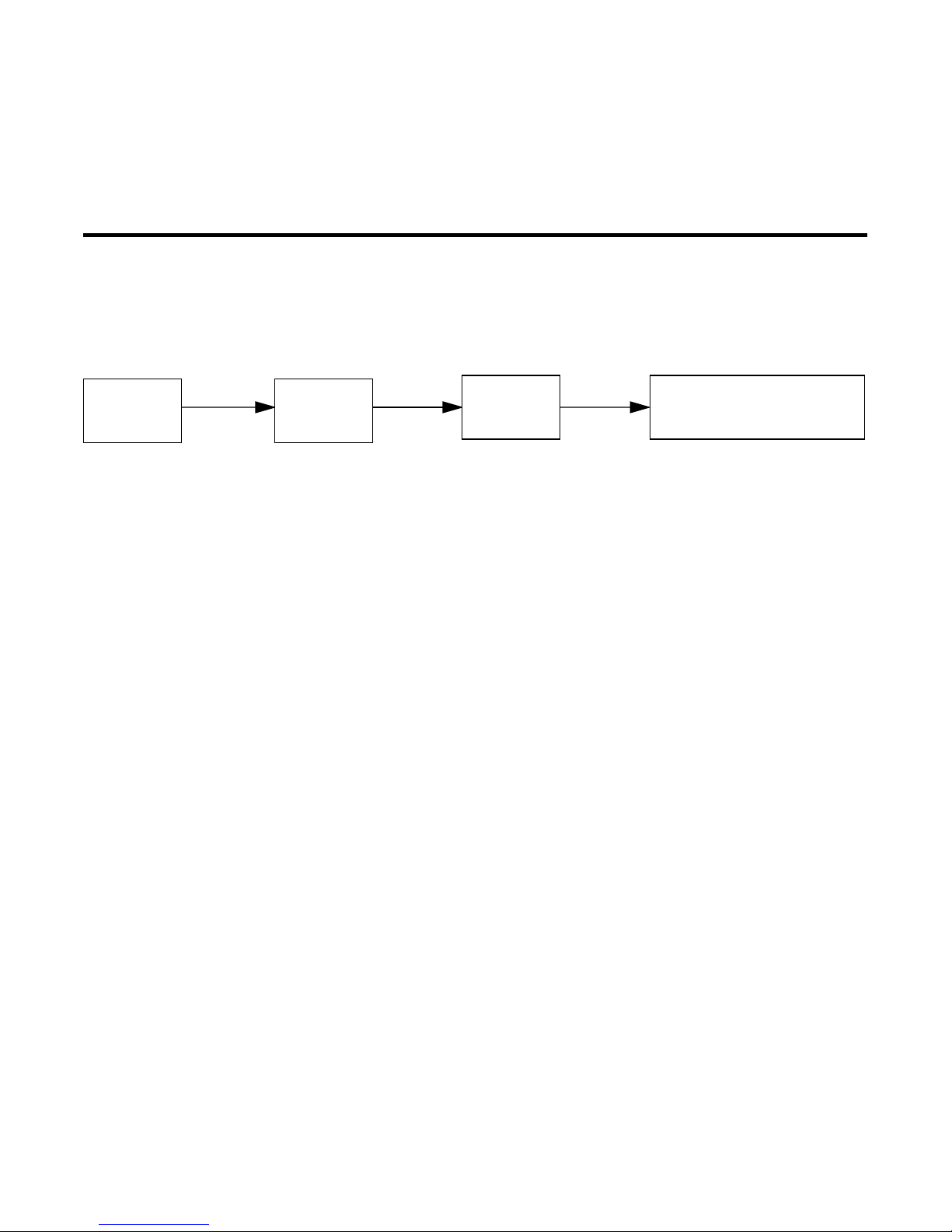
Navigating through the Advanced Configuration screens
To help you find your way to particular screens, some sections in this
guide begin with a graphical path guide similar to the following
example:
Main
Menu
Advanced
Config.
This particular path guide shows how to get to the WAN Setup
screens. The path guide represents these steps:
1. Beginning in the Main Menu, select the
item and press Return.
2. Select the
and press Return.
3. Select the
Answer Profile
To go back in this sequence of screens, use the Escape key.
W AN Setup
ISDN Line Configuration, Connection Profiles
WAN
Setup
item in the Advanced Configuration screen
item in the WAN Setup screen and press Return.
• ISDN Line Config.
• Connection Profiles
• Answer Profile
Advanced Configuration
, or
Page 15

Introduction 1-7
Keyboard navigation
Use your keyboard to navigate the Netopia Router’s configuration
screens, enter and edit information, and make choices. The following
table lists the navigation keys.
To... Use These Keys...
Move through selectable items in a
screen or pop-up menu
Execute action of a selected item or
open a pop-up menu of options for a
selected item
Change a toggle value
(Yes/No, On/Off)
Restore an entry or toggle value to
its previous value
Move one item up Ctrl + k
Move one item down Ctrl + j
Dump the device event log ^E
Dump the ISDN event log ^F
Refresh the screen ^L
Go to topmost selectable item <
Up, Down, Left, and
Right Arrow
Return or Enter
Tab
Esc
Go to bottom right selectable item >
Page 16

1-8 Reference Guide
Page 17

Chapter 2
Configuring ISDN and Leased Line Connections
This chapter shows you how to configure the Netopia Router to
make and receive network connections over an ISDN or leased line
and how to control those connections. Topics include:
■
“ISDN WAN Setup” on page 2-2 shows you how to configure
your ISDN Netopia Router for outgoing calls.
■
“Leased line WAN Setup” on page 2-5 shows you how to
configure your SA/Serial, DDS, or T1 Netopia Router for
outgoing calls.
2-1
“Connection profiles for ISDN and Leased lines,” beginning on
■
page 2-13, shows you how to configure connection profiles for
your ISDN, SA/Serial, DDS, or T1 Netopia Router.
■
“Default profile,” beginning on page 2-39, shows you how to
set up an answer profile for incoming calls.
■
“WAN IP Address Serving,” beginning on page 2-48, discusses
how to configure the router to allocate an IP address to callers
from an address pool.
■
“Scheduled connections,” beginning on page 2-49, shows you
how to control the dates and times when connection profiles
can be used.
“CSU Backup,” beginning on page 2-55, describes how to
■
automatically switch from an internal CSU to the SA port during
a leased line failure.
Note:
have variations in the fields on certain screens. For example, there
are switched (dial-up) or permanent (nailed-up) circuit ISDN or
leased line models, as well as models that offer feature subsets
such as AppleTalk, SmartIP (Network Address Translation and WAN
IP Address Serving) and SmartPhone (Plain Old Telephone Service).
Your own Advanced Configuration screens may look different from
those illustrated in this chapter.
Netopia Router models offering different feature sets will
Page 18

2-2 Reference Guide
ISDN WAN Setup
Main
Menu
Advanced
Configuration
WAN
Setup
• Line Configuration
• Connection Profiles
• Default Answer Profile
The ISDN WAN Setup screen has three subscreens, each involving a
different aspect of using the ISDN line to control connections to
remote IP or IPX networks.
Note:
Guide
If you have completed Easy Setup (see the
Getting Started
), the information you have already entered will appear in
some of the Advanced Configuration screens.
To go to the WAN Setup screen, select
WAN Setup
in the Advanced
Configuration screen and press Return. A screen similar to the
following appears:
WAN Setup
Line Configuration...
Connection Profiles...
Default Answer Profile...
From here you will configure yours and the remote sites' WAN information.
ISDN line configuration
Enter the information provided by your telephone service provider in
the ISDN Line Configuration screen. Use the information recorded in
the
specifying this configuration information.
To go to the ISDN Line Configuration screen, select
Configuration
Line Configuration screen appears.
Getting Started Guide’s
in the WAN Setup screen. Press Return, and the ISDN
ISDN worksheet as a reference when
Line
Page 19

Configuring ISDN and Leased Line Connections 2-3
North America ISDN
models only
Note:
If your ISDN Line Configuration screen contains items that
are not discussed in this section, such as SPIDs, see Appendix C,
“ISDN Configuration Guide.”
The ISDN Line Configuration screen consists of up to three pop-up
menus and up to four editable fields.
ISDN Line Configuration
Circuit Type... Switched
Switch Type... National ISDN-1 (NI-1)
SPID 1: 510.238.4166.1
SPID 2: 510.238.4167.2
Directory Number 1: 510.577.4166
Directory Number 2: 510.238.4167
Data Link Encapsulation... PPP
Return/Enter goes to new screen.
Enter information supplied to you by your ISDN phone company.
1. Select
highlight
Permanent
Circuit Type
Switched
and press Return. From the pop-up menu,
if you have an ISDN switched line, or
if you have a dedicated or leased ISDN line. Press
Return.
If you select Switched, go to step 3. If you select Permanent, go
to step 2.
Note:
The Switch Type, SPIDs, and Directory Numbers apply
only to Switched ISDN service. If you select Permanent, these
fields are not displayed.
2. If you select Permanent as your circuit type, select
Usage
.
B-Channel
Page 20

2-4 Reference Guide
ISDN Line Configuration
Circuit Type... Permanent
B-Channel Usage... B1
Data Link Encapsulation... PPP
Enter information supplied to you by your ISDN phone company.
Outside North America
models only
North America models
only
North America models
only
From the pop-up menu, select the appropriate B-channel, such
as B1, B2, or Both. Then go to step 7.
Note:
A permanent ISDN circuit type only supports 64 kbps
and 128 kbps B-channel usages.
3. Select
Switch Type
and press Return. From the pop-up menu,
select the switch protocol your ISDN service provider uses.
Observe these guidelines:
■
NI-1 can appear on an AT&T 5ESS or a Northern Telecom
DMS-100 Switch. Do not confuse it with a
custom
ISDN
implementation, which also appears on these two
switches.
■ Countries not shown in the list may use the generic
EuroISDN protocol.
4. Select SPID 1 and enter the primary SPID number. If you did
not receive a SPID (AT&T 5ESS custom point-to-point switches
have no SPID), you should skip this and the following step.
5. If you have a second SPID, select SPID 2 and enter the
secondary SPID number.
Note: SPID1 and SPID2 are not displayed for models outside
North America.
Page 21

Configuring ISDN and Leased Line Connections 2-5
6. Select Directory Number 1 and enter the primary directory
number as you would dial it, including any required prefixes
(such as area, access, and long-distance dialing codes). Press
Return.
Note: If you select an IDSL (Pt-to-Pt) switch, the Directory
Number 1 field will default to 555-1234.
Since an IDSL line is already physically hooked up in a pt-to-pt
configuration, a specific directory number is not necessary.
However, the Netopia Router does require a directory number in
this field to allow a connection to dial out.
7. If you have a second directory number, select Directory
Number 2 and enter the secondary directory number as you
would dial it, including any required prefixes (such as area,
access, and long-distance dialing codes). Press Return.
8. Select Data Link Encapsulation and highlight the method of
In order for the changes that you have entered in the ISDN Line
Configuration screen to take effect, you must reset the Netopia
Router. Press the Escape key to return to the Main Menu. Select
Statistics, Utilities, Tests and then select Restart System.
Leased line WAN Setup
Main
Menu
Advanced
Configuration
The leased line WAN Setup screen will vary for an SA/Serial, 56k
DDS, or T1 line depending on the circuit type and datalink
encapsulation parameter that is selected for that specific leased
line.
encapsulation that you want to use from the pop-up menu. The
choices offered are PPP or HDLC. Press Return.
WAN
Setup
• Line Configuration
• Frame Relay Configuration
• Frame Relay DLCI Configuration
• Connection Profiles
• Default Profile
To begin WAN Setup, select WAN Setup in the Advanced
Configuration menu, then press Return.
Page 22

2-6 Reference Guide
WAN Setup
Line Configuration...
Frame Relay Configuration...
Frame Relay DLCI Configuration...
Connection Profiles...
Default Profile...
From here you will configure yours and the remote sites' WAN
information.
Note: For all leased line Netopia Router models using PPP or CiscoHDLC datalink encapsulation, the Frame Relay Configuration and
Frame Relay DLCI Configuration options will be hidden.
For all leased line Netopia Router models using Cisco-HDLC datalink
encapsulation, the Default Profile option will remain hidden.
If you have completed Easy Setup (see the
Getting Started Guide
),
the information you have already entered will appear in some of the
WAN Setup screens.
Leased line configuration
The following Leased line configuration section describes the first
step in configuring the Line Configuration screen in the WAN Setup
menu for an SA/Serial, T1, and DDS Netopia Router wanlet module
with PPP, Cisco-HDLC, or Frame Relay datalink encapsulation
enabled.
The Serial Line Configuration screen appears for SA/Serial leased
line models (with an external CSU/DSU connection). See below.
The T1 Line Configuration screen appears for T1 leased line models
(with an internal CSU/DSU connection). See page 2-9.
Page 23

Configuring ISDN and Leased Line Connections 2-7
The DDS Line Configuration screen appears for DDS leased line
models (with an internal CSU/DSU connection). See page 2-12.
Line configuration for an SA/Serial line
The Serial Line Configuration screen is where you enter the
configuration parameters for your leased line, in order for the
Netopia Router to communicate with the physical connection. Use
the information in the Leased Line worksheet in the
Guide
, as a reference when specifying this configuration
Getting Started
information.
Permanent circuit only
Serial Line Configuration
Circuit Type... Permanent Sync
Data Rate (kbps)... 64
Invert Tx Clock: No
Circuit Activation Requires... DCD and DSR
Data Link Encapsulation... Frame Relay
Enter Information supplied to you by your telephone company.
1. Select Circuit Type and select Permanent Sync or Switched
Async. If you select permanent sync, continue with Step 2. If
you select Switched Async, skip to Step 6.
2. Select Data Rate (kbps) and press Return. From the pop-up
menu, select a fixed data rate for your digital line or select
Auto. (The data rates to choose from range from 56 kbps to the
highest synchronized line speed.) The Auto setting allows your
Netopia Router to determine the data rate of your serial line at
the time of circuit activation. Press Return.
Permanent circuit only 3. Select Invert Tx Clock and toggle to Yes or No depending on
whether you use this selection. Press Return.
Invert Tx Clock causes transmitted data to be delayed by half a
clock phase. This option is useful for X.21 DTEs (Data T erminal
Page 24

2-8 Reference Guide
Equipment) because their transmit data can become altered in
relation to the clock sourced by the DCE (Data Communications
Equipment).
A DTE (Data Terminal Equipment) is a term used to define the
equipment rate. It is a designation for the maximum rate at
which a router can exchange information.
A DCE (Data Communications Equipment) is a term defined by
both Frame Relay and X.25 committees, that applies to
switching equipment and is distinguished from the devices that
attach to the network (DTE).
Permanent circuit only 4. Select Circuit Activation Requires and select DCD-only,
DSR-only, or DCD and DSR. Press Return.
Some V .35 interfaces represent their capability to transfer user
data end-to-end with the DCD signal, while others offer a more
accurate representation with DSR. For this latter case, you may
choose to use DSR-only.
Switched circuit only
Note: This option will be hidden if an X.21 cable is attached.
5. Select Data Link Encapsulation and highlight the method of
encapsulation that you want to use from the pop-up menu. The
choices offered are PPP, HDLC, and Frame Relay. The default
setting is Frame Relay. Press Return.
Continue to the last step.
Serial Line Configuration
Circuit Type... Switched Async
Data Rate (kbps)... 57.6
Modem Initialization String: AT&C1&D2E0S0=1
Modem Dialing Prefix: ATDT
Data Link Encapsulation is Async PPP
Page 25

Configuring ISDN and Leased Line Connections 2-9
Switched async only 6. Select Date Rate (kbps) and press Return. From the pop-up
menu, select 19.2, 38.4, 57.6, 115.2, or 230.4. Choose the
data rate that is about twice your modem’s capabilities. For
instance, if you have a 28.8K modem, select 57.6 for your data
rate. Press Return.
7. The Modem Initialization String and Modem Dialing Prefix
fields configure the connection to the external modem. For
information on editing this configuration, see the Netopia
Router 3.2 Release Note.
8. The Data Link Encapsulation is set to Async PPP.
9. You are now finished configuring the Serial Line Configuration
screen. Press the Escape key to return to the WAN Setup
screen. Go to page 2-13 for information on how to configure
your leased line connection profile.
Line configuration for a T1 line
The T1 Line Configuration screen is where you enter the
configuration parameters for your leased line, in order for the
Netopia Router to communicate with the physical connection. Use
the information in the Leased Line worksheet in the Getting Started
Guide as a reference when specifying your T1 configuration
information.
Page 26

2-10 Reference Guide
T1 Line Configuration
Line Encoding... B8ZS
Framing Mode... ESF
Transmit ANSI PRMs: No
Number of DS0 Channels: 1
First DS0 Channel: 1
Buildout (-dB)... Auto
Channel Data Rate... Nx64k
Clock Source... Network
Data Link Encapsulation... Frame Relay
Enter Information supplied to you by your telephone company.
1. Select Line Encoding and press Return. From the pop-up menu,
highlight the encoding your telephone service provider uses:
B8ZS or AMI. The default setting is B8ZS. Press Return.
2. Select Framing Mode and press Return. From the pop-up
menu, highlight either ESF or D4, depending on the framing
mode that your telephone service provider advises you to use.
The default setting is ESF. Press Return.
3. The ANSI T1.403 standard defines Performance Report
Messages (PRMs) that may be transmitted each second from a
T1 Integrated CSU to the telephone service provider’s network.
By default, the Netopia Router does not send PRMs. However,
you can enable these transmissions by toggling Transmit ANSI
PRMs to Yes.
4. Select Number of DS0 Channels and enter the number of DS0
channels that you and your telephone service provider have
determined are necessary for your T1 line. The default setting
for DS0 Channels is 1 (one). Press Return.
Page 27

Configuring ISDN and Leased Line Connections 2-11
Note: Each DS0 channel represents a 56k or 64k increment in
bandwidth. Selecting a number less than the maximum of 24
specifies a fractional-T1 interface.
For fractional-T1, you may also specify in the check box whether
the DS0 channels are contiguous or alternating.
5. Select First DS0 Channel and enter the number of the first
active DS0 channel you will be using. The default setting is 1
(one). Press Return.
Note: You may change the First DS0 Channel number, which
has a valid range from one to the maximum number minus the
number of active channels. If the number of active DS0
channels is 24 (maximum), First DS0 Channel is hidden.
6. Select Buildout (-dB) and press Return. From the pop-up menu,
highlight the line Buildout, which is the transmit attenuation of
your line that you will be using. The choices in the menu include
Auto, 0-0.6, 7.5, 15.0, 22.5, and None. The default setting is
Automatic. Press Return.
If Automatic is chosen, the attenuation of the transmission will
be set to match the receiving signal level.
7. Select Channel Data Rate and highlight the data rate specified
by your service provider. The channel data rate choices are
Nx56k or Nx64k. The default is Nx64k. Press Return.
8. Select Clock Source and press Return. From the pop-up menu,
highlight the clock source, that you wish to use. The choices
offered are Internal Clock Source, or Network Clock Source.
The default is Network. Press Return.
9. Select Data Link Encapsulation and highlight the method of
encapsulation that you want to use from the pop-up menu. The
choices offered are PPP, HDLC, and Frame Relay. The default
setting is Frame Relay. Press Return.
10. You are now done configuring the Line Configuration screen.
Press the escape key to return to the WAN Setup screen. Go to
page 2-13, for information on how to configure your leased line
connection profile.
Page 28

2-12 Reference Guide
Line configuration for a DDS line
The DDS Line Configuration screen is where you enter the
configuration parameters for your leased line, in order for the
Netopia Router to communicate with the physical connection. Use
the information in the Leased Line worksheet in the Getting Started
Guide as a reference when specifying your DDS line configuration
information.
DDS Line Configuration
Circuit Type... Permanent
Data Rate... Auto
Clock Source... Network
Data Link Encapsulation... Frame Relay
Enter Information supplied to you by your telephone company.
1. Select Circuit Type and press Return. From the pop-up menu,
highlight Switched for a dial-up digital line or Permanent for a
nailed-up leased line. The default setting is Permanent. Press
Return.
Note: The DDS data rate is capable of handling 56 or 64 kbps.
If the Switched circuit type is selected, 56 kbps data rate is the
only available option. If the Permanent circuit type is selected,
56 kbps and 64 kbps data rates will be available.
2. Select Data Rate and press Return. From the pop-up menu,
highlight the data rate that you want your DDS line connection
to transmit at. The data rate choices are 56 kbps and 64 kbps.
The default is Automatic. Press Return.
Note: As noted above, DDS Netopia Routers may run 56 kbps
or 64 kbps data rates on permanent circuits. You may
alternately select Automatic, in which case the router will hunt
between modes until it can determine what the telephone
company has provisioned your DDS line for.
Page 29

Configuring ISDN and Leased Line Connections 2-13
3. Select Clock Source and press Return. From the pop-up menu,
highlight the clock source, that you wish to use. The choices
offered are Internal Clock Source, or Network Clock Source.
The default is Network. Press Return.
4. Select Data Link Encapsulation and highlight the method of
encapsulation that you want to use from the pop-up menu. The
choices offered are PPP, HDLC, and Frame Relay. The default
setting is Frame Relay. Press Return.
5. You are now done configuring the Line Configuration screen.
Press the escape key to return to the WAN Setup screen. Go to
page 2-13, for information on how to configure your leased line
connection profile.
Connection profiles for ISDN and Leased lines
A connection profile is a set of parameters that tells the Netopia
Router how to connect to a remote destination. Connection profiles
are also used to make out-bound calls and optionally to help answer
calls.
Some Netopia models support up to 4 different connection profiles
while most models support up to 16 connection profiles.
To go to the Connection Profiles screen, select Connection Profiles
in the WAN Setup screen.
Page 30

2-14 Reference Guide
Connection Profiles
Display/Change Connection Profile...
Add Connection Profile...
Delete Connection Profile...
Establish WAN Connection...
Disconnect WAN Connection...
Return/Enter to modify an existing Connection Profile.
This Screen is the main point of navigation for Connection Profiles.
Note: The Establish WAN Connection and Disconnect WAN
Connection fields in the Connection Profiles screen will only appear
for a Netopia Router model with switched circuit selected. This field
will remain hidden when permanent circuit is selected.
Displaying connection profiles
To display a view-only table of connection profiles, select
Display/Change Connection Profile in the Connection Profiles
screen. Press Return and the connection profiles that you have
created will appear.
The Connection Profiles table is a handy way to quickly see the
names and destination IP or IPX addresses of your connection
profiles.
Page 31

Configuring ISDN and Leased Line Connections 2-15
Connection Profiles
+-Profile Name---------------------IP Address----IPX Network-+
+------------------------------------------------------------+
| Easy Setup Profile 127.0.0.2 0 |
| Panost Inc. 0.0.0.0 |
| XYZ Corporation 0.0.0.0 |
+------------------------------------------------------------+
Up/Down Arrow Keys to select, ESC to dismiss, Return/Enter to Edit.
Changing a Connection Profile
To modify a connection profile, select Display/Change Connection
Profile in the Connection Profiles screen to display a table of
connection profiles.
Select a connection profile from the table and press Return to go to
the Change Connection Profile screen. The parameters in this
screen are the same as the parameters found in the Add
Connection Profile screen. To find out how to set them, see “Adding
a connection profile” on page 2-16.
Change Connection Profile
Profile Name: Panost Inc.
Profile Enabled: Yes
IP Enabled: Yes
IP Profile Parameters...
IPX Enabled: Yes
IPX Profile Parameters..
Data Link Encapsulation... PPP
Data Link Options...
Telco Options...
Modify Connection Profile here. Changes are immediate.
Page 32

2-16 Reference Guide
Deleting a Connection Profile
To delete a connection profile, select Delete Connection Profile in
the Connection Profiles screen and press Return to display a table
of connection profiles.
Connection Profiles
+-Profile Name---------------------IP Address----IPX Network-+
+------------------------------------------------------------+
| Gunther Hydroelectric 127.0.0.2 0 |
+------------------------------------------------------------+
+------------------------------------------------------------+
| Are you sure you want to delete this Connection Profile? |
| |
| CANCEL CONTINUE |
| |
| |
+------------------------------------------------------------+
1. Highlight the connection profile you wish to delete. Press
Return.
2. A connection profile table appears with a prompt asking you if
you want to delete the connection profile you have just
highlighted. Select CONTINUE if you wish to delete this
connection profile or CANCEL if you do not.
Adding a Connection Profile
To add a new connection profile, select Add Connection Profile in
the Connection Profiles screen. Press Return and the Add
Connection Profile screen appears.
Page 33

Configuring ISDN and Leased Line Connections 2-17
Add Connection Profile
Profile Name: Profile 04
Profile Enabled: Yes
IP Enabled: Yes
IP Profile Parameters...
IPX Enabled: Yes
IPX Profile Parameters..
Data Link Encapsulation... PPP
Data Link Options...
Interface Group... Int CSU
Telco Options...
ADD PROFILE NOW CANCEL
Configure a new Conn. Profile. Finished? ADD or CANCEL to exit.
1. Select Profile Name and enter a name for this connection
profile. It can be any name you wish. For example: the name of
your ISP.
2. Select Profile Enabled and toggle it to Yes to activate the
profile.
3. Select IP Enabled and toggle it to Yes or No depending on
whether you will be using TCP/IP over your WAN connection.
4. Select IP Profile Parameters. This option is only available if IP
Enabled is toggled to Yes.
Page 34

2-18 Reference Guide
IP Profile Parameters
Address Translation Enabled: Yes
IP Addressing... Numbered
Local WAN IP Address: 0.0.0.0
Local WAN IP Mask: 0.0.0.0
Remote IP Address: 0.0.0.0
Remote IP Mask: 0.0.0.0
Filter Set...
Remove Filter Set
Receive RIP: Yes
Applicable only to SmartIP
models
Configure IP requirements for a remote network connection here.
5. In the IP Profile Parameters screen, toggle Address Translation
Enabled to Yes if you choose to use Network Address
Translation.
Network Address Translation allows communication between
the LAN connected to the Netopia Router and the Internet using
a single IP address, instead of a routed account with separate
IP addresses for each computer on the network. Network
Address Translation also provides increased security by hiding
the local IP addresses of the LAN connected to the Netopia
Router from the outside world.
Note: See “Summary of the Netopia Router models and
features” on page 1-5 of the
■ If you did not enable Network Address Translation, select IP
Getting Started Guide
.
Addressing and, from the pop-up menu, choose the IP routing
method that your ISP or network administrator specifies (either
Numbered or Unnumbered).
■ If your ISP uses Numbered (Interface-based) Routing, select
Local WAN IP Address and enter the local WAN address your
ISP gave you. Then select Local WAN IP Mask and enter the
WAN subnet mask of the remote site you will connect to.
Page 35

Configuring ISDN and Leased Line Connections 2-19
The default address for the Local WAN IP Address is 0.0.0.0,
which allows for dynamic addressing, when your ISP assigns an
address each time you connect. However, you may enter
another address if you want to use static addressing.
Note: When using Cisco-HDLC datalink encapsulation and
Network Address Translation, you must use a static address.
When using numbered interfaces, the Netopia Router will use
its local WAN IP address and subnet mask to send packets to
the remote router. Both routers have WAN IP addresses and
subnet masks associated with the connection.
IP Profile Parameters
Address Translation Enabled: No
IP Addressing... Unnumbered
Remote IP Address: 0.0.0.0
Remote IP Mask: 0.0.0.0
Filter Set...
Remove Filter Set
Receive RIP: No
Transmit RIP: No
Configure IP requirements for a remote network connection here.
■ If your ISP uses Unnumbered (System-based) Routing, select
Remote IP Address and enter the IP address your ISP gave you.
Then select Remote IP Mask and enter the IP subnet mask of
the remote site you will connect to.
Note: If your ISP has not given you their IP or subnet mask
addresses, then you may enter an IP address such as
127.0.0.2 and an IP subnet mask such as 255.0.0.0.
When using unnumbered interfaces, the Netopia Router will
use either its local Ethernet IP address or its NAT (Network
Address Translation) address (if so configured) and subnet
mask to send packets to the remote router. Neither router has
Page 36

2-20 Reference Guide
a WAN IP address or subnet mask associated with this
connection. These default addresses will request that the
remote router dynamically assign an address at the time the
connection is made.
To configure a profile for a terminal adapter or Netopia Router
that is dialing into your router using dynamic Network Address
Translation, you may enter a 0.0.0.0 remote IP address and
enable IP WAN Address Serving.
Note: If you are interested in serving a WAN IP Address to an
incoming caller, see “WAN IP Address Serving” on page 2-48.
■ Select Filter Set and then select an appropriate filter set from
the list. If you do not want to block any TCP/IP traffic, then
leave this entry blank.
■ To remove a filter set, select Remove Filter Set and press
Return. A pop-up menu will appear displaying the filter sets you
have set up previously. Highlight the specific filter set that you
want to remove and press Return. A window will appear asking
you if you are sure that you want to delete that specific filter
set. You can either select Continue or Cancel.
■ Select Receive RIP and toggle it to Yes if you want the Netopia
Router to receive RIP information sent by remote routers that
are connected to your local area network (LAN).
■ Select Transmit RIP and toggle to Yes if you want the Netopia
Router to send RIP information to remote routers that are
connected to your LAN. If Transmit RIP has been enabled, the
TX RIP Policy field will appear. Select TX RIP Policy and press
Return and the Poison Reverse field will appear.
■ Press the Escape key when you are finished configuring IP
Profile Parameters to go back to the Add Connection Profile
screen. The next step describe how to configure the IPX
parameters. If you do not wish to enable IPX, skip to step 7,
which describes how to set up Data Link Encapsulation.
6. From the Add Connection Profile screen, select IPX Enabled
and toggle it to Yes or No depending on whether you will be
using IPX over your ISDN connection.
Page 37

Configuring ISDN and Leased Line Connections 2-21
Note: Using the IPX protocol is required with other remote
networks using IPX for an intranet connection. For more
information on IPX, refer to Chapter 5, “IPX Setup” of this
guide.
■ Select IPX Profile Parameters and press Return. This option is
only available if IPX Enabled is toggled to Yes.
IPX Profile Parameters
Remote IPX Network: 00000000
Path Delay: 10
NetBios Packet Forwarding: Off
Incoming Packet Filter Set... <<NONE>>
Outgoing Packet Filter Set... <<NONE>>
Incoming SAP Filter Set... <<NONE>>
Outgoing SAP Filter Set... <<NONE>>
Periodic RIP Timer: 60
Periodic SAP Timer: 60
Configure IPX requirements for a remote network connection here.
■ Select Remote IPX Network and enter the network address of
the IPX network being called. Do not use an address already in
use by another connection profile. If this value is set to zero
and the Netopia Router is answering a call, the remote address
will be learned when the profile is active.
Note: If you are trying to connect two Netopia Routers using
Frame Relay and IPX, be sure to enter an IPX address for the
remote side in the connection profiles. If the remote IPX
address is all zeros (the default), the two Netopia Routers will
not be able to connect.
Note: Unlike IP, the IPX network address is never used in
matching a profile when answering a non-authenticated call.
Page 38

2-22 Reference Guide
■ To change the default Path Delay, select and enter a value (in
ticks).
■ To enable NetBIOS Packet Forwarding, toggle the selection to
Yes.
■ Select Incoming Packet Filter Set to attach a filter set for
filtering incoming packets. Choose a filter set from the list and
press Return.
■ Select Outgoing Packet Filter Set to attach a filter set for
filtering outgoing packets. Choose a filter set from the list and
press Return.
■ Select Incoming SAP Filter Set to attach a filter set for filtering
server entries within incoming Service Advertising Protocol
(SAP) packets. Choose a filter set from the list press Return.
■ Select Outgoing SAP Filter Set to attach a filter set for filtering
server entries within outgoing Service Advertising Protocol
(SAP) packets and choose a filter set from the list.
■ Select Periodic RIP Timer, and enter a new value (in seconds)
to change the periodic RIP timer’s default value.
■ Select Periodic SAP Timer, and enter a new value (in seconds)
to change the periodic SAP timer’s default value.
■ Press the Escape key to go back to the Add Connection Profile
screen when you are finished configuring IPX Profile
Parameters.
For more information on creating an IPX filter set, go back to the
Advanced Configuration screen and select the Filter Sets (Firewalls)
screen. Also refer to Chapter 6, “IPX Setup”.
7. Select Data Link Encapsulation and highlight the method of
encapsulation that you want to use from the pop-up menu. The
choices offered are PPP, HDLC, or Frame Relay. Press Return.
If you have enabled PPP/MP, go to step 8. If you have enabled
Frame Relay , go to step 9. If you have enabled HDLC, go to step
11.
8. Select Data Link Options and press Return. The PPP/MP
Options screen appears.
Page 39

Configuring ISDN and Leased Line Connections 2-23
Point-to-Point Protocol (PPP) and Multilink Point-to-Point Protocol
(MP) allow the Netopia Router to make adaptable and secure
connections to other networks.
PPP/MP Options
Data Compression... Ascend LZS
Send Authentication... PAP
Send User Name:
Send Password:
Receive User Name:
Receive Password:
Applicable only to
Switched circuits
B-Channel Usage... Dynamic
BAP Usage... Off
Return/Enter to choose PPP Authentication type (or None).
■ Select the Data Compression pop-up menu, choose the type of
data compression supported by the network you are calling,
and press Return. The choices are Ascend LZS, Standard LZS,
or None (if the remote network does not use Ascend LZS or
Standard LZS). Ascend LZS is compatible with the type used by
Ascend Communications. This is the default setting for Data
Compression, as most ISP’s (Internet Service Providers) and
remote networks use Ascend’s proprietary data compression
utility. Standard LZS is an IETF (Internet Engineering Task
Force) standard for LZS data compression.
■ Select the Send Authentication pop-up menu and choose the
type of connection security supported by the network you are
calling. From the pop-up menu highlight PAP, CHAP,
PAP-TOKEN, CACHE-TOKEN, or None (if the remote network
does not use PAP or CHAP). On the Netopia Router the default
Page 40

2-24 Reference Guide
authentication is set for P AP, as this is usually the most popular
security parameter that ISP’s and other remote networks set up
for a point-to-point connection use.
■ If you choose None, and the remote network expects to
connect to the Netopia Router using this connection profile, you may need to set the answer profile to accept calls
using no authentication (None). See “Default profile” on
page 2-39.
■ If you choose to use PAP for calling the remote network,
you will need to obtain a name and password from the
remote network’s administrator. Enter the name in Send
User Name and enter the password in Send Password. If
you want the remote network to use this connection profile
when it calls the Netopia Router, select Receive Name and
enter a name. Select Receive Password and enter a password. You will need to give this name and password to the
remote network’s administrator.
If you choose PAP , and the remote network expects to connect
to the Netopia Router using this connection profile, you may
need to set the answer profile to accept calls using PAP. See
“Default profile” on page 2-39.
■ If you choose to use CHAP for calling the remote network,
obtain a name and secret (the CHAP term for password)
from the remote network’s administrator. Enter the name
in Send Host Name and enter the password in Send
Secret. If you want the remote network to use this connection profile when it calls the Netopia Router, select Receive
Host Name and enter a name. Select Receive Secret and
enter a secret. You will need to give this name and secret
to the remote network’s administrator.
Note: If you choose CHAP, and the remote network expects to
connect to the Netopia Router using this connection profile, you
may need to set the answer profile to accept calls using CHAP.
See “Default profile” on page 2-39.
■ If you choose to use PAP-TOKEN, select Send User Name
and enter a name for your Netopia Router. You will not
need to enter a Send Password for PAP-TOKEN.
Page 41

Configuring ISDN and Leased Line Connections 2-25
■ If you choose to use CACHE-TOKEN, select Send User
Name and enter a name for your Netopia Router. Then,
select Send Password and enter a secret name or number .
If you will be using SecurID (an added method of security
authentication), check with your network administrator to find
out if you will need to use either PAP-TOKEN, or
CACHE-TOKEN. (Also, see Chapter 9, “Security-Token
Authentication”.)
PPP/MP Options
Data Compression... Ascend LZS
Applicable only to
Switched circuits
Send Authentication... PAP
Send User Name:
Send Password:
Receive User Name:
Receive Password: +-------------------+
+-------------------+
B-Channel Usage... | Dynamic |
| 1 B-Channel |
BAP Usage... | 2 B-Channels |
| 2 B, Preemptable |
Maximum Packet Size: +-------------------+
■ Select B-Channel Usage and choose how this connection
profile will use the ISDN line’s B-channels. From the pop-up
menu highlight either Dynamic, 1 B-Channel, 2 B-Channels, or
2 B, Pre-emptable.
■ Dynamic (default setting), allows the connection profile to
use one or both channels at any time during a call. The
decision to alternately use or drop the second B-channel is
based on an algorithm that looks at traffic volume over
time. With Dynamic, one B-channel may be relinquished to
Page 42

2-26 Reference Guide
accept an incoming call through or when a second connection profile is used to make a call. See Appendix D for information on “Dynamic B-channel usage”.
■ 1 B-Channel forces a call to remain within one B-channel.
(Throughput will generally be at either 56k or 64k, depending on how the local telephone company installs your ISDN
line. This will also depend on certain geographic locations
in North America. The standard ISDN data rate outside of
North America is 64k.)
■ 2 B-Channels forces a call to use both B-channels.
(Throughput connection will generally run at 128k.)
■ 2 B Pre-emptable allows calls to use 2 B-channels in a
dynamic, Pre-emptable manner. This option is very similar
to Dynamic, in that the second B-channel may be relinquished to accept an incoming call or to initiate a second
outgoing call. However, 2B Pre-emptable will always try to
add a second B-channel to the call when the second channel is otherwise unused, much like a fixed 2 B-channel
selection.
Applicable only to
Switched circuits
Note: If you select Dynamic or 2 B, Pre-emptable while using
PPP/MP, the Netopia Router may attempt to use both
B-channels during a call. However, during a call, your second
B-channel may be blocked from use if the answering side drops
that B-channel before you begin sending data over it. The
Netopia Router will try four times to bring up the second
B-Channel; if all attempts fail and you wish to retry, end the call
and reinitiate it.
■ Select BAP Usage and from the pop-up menu highlight the
method of BAP usage that your ISP or network administrator
has suggested that you use when establishing a connection to
a remote site. The choices offered for BAP usage are On - Old
IDs, On - New IDs, and Off. Press Return.
BAP refers to the PPP Bandwidth Allocation Control Protocol.
The BAP Usage feature allows a Netopia Router to either dial
out to provide a telephone number for a multilink call, or allows
the Netopia Router to answer a call, while also providing a
Page 43

Configuring ISDN and Leased Line Connections 2-27
telephone number for a multilink call. In addition, the Netopia
Router can bring WAN links up and down with a remote router.
Note: There are two specifications for BAP protocol. The first
specification was proposed before January 1997 and the latter
was proposed after that date.
The On-Old IDs selection refers to the earlier BAP proposal and
On-New IDs refer to the new proposal.
Because there is no set standard at this time for BAP protocol
the Netopia Router allows you to select either specification.
Models with Frame Relay
enabled only
9. Select Data Link Options and press Return. The Frame Relay
Parameters screen appears.
Frame Relay Parameters
Auto-Detect DLCIs: Yes
Multicast DLCI Number: 0
Configure Frame Relay-specific parameters of your Connection Profile
here.
■ Select Auto-Detect DLCIs and toggle to either Yes or No. If you
select Yes, you are enabling your Frame Relay profile to
auto-detect the DLCIs associated with its network layer
attributes. This feature is also called SmartMatch. If you select
No, you will need to manually configure each DLCI in the DLCI
configuration table. See “Frame Relay DLCI configuration” on
page 2-34. The default setting for this option is Yes. Press
Return.
■ Select Multicast DLCI Number. In this field you may add a
number that will be used for multicasting in conjunction with the
network layer attributes of your given profile. The default setting
for this option is 0. If you choose to leave 0 as the value for this
field, the specific profile that you are configuring will not be
used for multicasting.
Page 44

2-28 Reference Guide
T1 and DDS models only 10. The Interface Group field reflects the active port selection: the
internal CSU for T1 or DDS, or SA port for SA, if backup is
enabled. See “CSU Backup” on page 2-55 for more
information.
Models with Switched
circuits only
11. Select Telco Options and press Return. The Telco Options
screen appears. The Telco Options screen contains items that
allow you to control the calls made on the WAN line with this
particular connection profile.
Telco Options
Initiate Data Service... 64 kb/sec
Dial... Dial In/Out
Number to Dial:
Alternate Number to Dial:
Dial On Demand: Yes
Idle Timeout (seconds): 300
CNA Validation Number:
Callback: No
In this Screen you configure options for the ways you will establish a
link.
ISDN Switched circuit
■ Select Initiate Data Service and choose the correct ISDN
models only
bandwidth to use with this connection profile. In North America,
users are not guaranteed of having a 64k connection to their
destination, but only when 64k is not available from point A to
point B should 56k be selected. The Router automatically falls
back to 56k when 64k service is not available. It is advised to
select 56k when you know that the 64k service will fail. You
may also select Speech if your line is provisioned for this
feature and the call is within your local ISDN region. Selecting
Speech may save money, but it is not guaranteed to work
outside of your switch.
Page 45

Configuring ISDN and Leased Line Connections 2-29
■ Select Dial and set this connection profile to only make calls,
only receive calls, or do both. Choose from In Only (receive
calls), Out Only (make calls), or Dial In/Out (receive and make
calls).
■ Select Number to Dial and enter the telephone number you
received from your ISP. This is the number the Netopia Router
dials to reach your ISP. Enter the number as you would dial it,
including any required prefixes (such as area, access, and
long-distance dialing codes).
If you selected IDSL (Pt-to-Pt) as your Netopia Router’s switch
type the connection profile’s number to dial will default to
555-4321. The same default information applies to this
number as the directory number, in order for the Netopia Router
to allow a connection to dial out.
Available for outbound
calls only
Note: If you previously selected Permanent as your router’s
Circuit Type in the ISDN Easy Setup screen, Number to Dial will
not be an available option.
■ Select Alternate Number to Dial if your ISP requires that you
use a second telephone number to dial, or as an alternative
backup when the first channel is unavailable to use.
■ Select Dial On Demand and toggle No if manual connections
are required for this profile. The default for Dial On Demand is
Yes, which is correct for most uses. When Dial On Demand is
set to Yes, the Netopia Router can automatically make calls as
the need arises, such as when a request to connect to a host
on the Internet is made by a computer on the local network.
Dial on demand also comes into action when IP and or IPX
traffic needs to go to a route defined by the profile attributes.
Every dial-on-demand profile becomes a part of the routing
table.
See “Establishing a WAN Connection” on page 2-30 for more
information.
■ Select Idle Timeout (seconds) and enter the time limit desired
before the Netopia Router drops a call if there is no activity on
the line. The default timeout setting is 300 seconds (5
minutes.)
Page 46

2-30 Reference Guide
ISDN Switched circuit
models only
Available for inbound calls
only
Available for inbound calls
only
■ The CNA Validation Number is the telephone number that your
Netopia Router will match to incoming calls. Question marks
“?” can be used in place of numbers as wild card characters to
ensure that matches are made on different directory numbers.
See “Default profile” on page 2-39 for information on CNA
(Calling Number Authentication).
■ Select Callback and toggle to Yes to drop incoming answered
calls and use this connection profile to call the remote network
back. (See “Default profile” on page 2-39 for information on
incoming calls matching connection profiles). The default for
Callback is No.
You are now finished configuring the Telco options screen.
Press the Escape key to return to the Add Connection Profile
screen.
12. From the Add Connection Profile screen, select ADD PROFILE
NOW to save the current connection profile information that you
have just entered, and press Return to go to the Connection
Profiles screen. Alternatively, you can cancel the connection
profile you have just constructed by selecting CANCEL to exit
the Add Connection Profile screen.
Switched circuit models
only
Establishing a WAN Connection
To establish a manual WAN connection call, select Establish WAN
Connection from the Connection Profiles screen and press Return.
The Establish WAN Connection pop-up menu displays a table of all
of the connection profiles you have previously defined. Highlight the
connection profile you wish to manually call. Press Return and the
connection you select will initiate a call.
Call Status
Profile Name -- Panost, Inc.
Connection State -- Acquiring
Hit ESCAPE/RETURN/ENTER to return to previous menu.
Page 47

Configuring ISDN and Leased Line Connections 2-31
If a connection is establishing properly, the Connection State will
initially read Acquiring but will change to Up once the call has
successfully connected. You will be able to access information at
the remote site that you are connecting to once authentication is
completed successfully.
Disconnecting a WAN Connection
Switched circuit models
only
To hang up a manual WAN connection call, select Disconnect WAN
Connection from the Connection Profiles screen and press Return.
The Disconnect pop-up menu displays a table of all of the
connection profiles you have previously defined. Highlight the
connection profile you wish to disconnect. Press Return and the
connection you select will be disconnected. Press Esc to cancel.
Frame Relay configuration
If you chose Frame Relay as your datalink encapsulation type you
will now need to configure your Netopia Router to support Frame
Relay. From the WAN Setup screen, select the Frame Relay
Configuration option and press Return.
The Frame Relay Configuration screen consists of two pop-up
menus. Use the information in the Leased Line worksheet in the
Getting Started Guide
configuration information.
as a reference when specifying this
Page 48

2-32 Reference Guide
Frame Relay Configuration
LMI Type... ANSI (Annex D)
T391 (Polling Interval in secs): 10
N391 (Polls/Full Status Cycles): 6
N392 (Error Threshold): 3
N393 (Monitored Event Window): 4
Tx Injection Management... Standard
Default CIR: 64000
Default Bc: 64000
Default Be: 0
Congestion Management Enabled: Yes
Maximum Tx Frame Size: 1536
Enter Information supplied to you by your telephone company.
1. Select LMI T ype (Link Management Type) and press Return. From
the pop-up menu, highlight either ANSI (Annex D), CCITT (Annex
A), LMI, or None. The world-wide default is ANSI (Annex D).
Press Return.
Note: If you select None as an LMI Type, the four LMI options
listed below will remain hidden, and you will need to manually
configure DLCIs. See “Frame Relay DLCI configuration” on
page 2-34 for instructions.
Specifying the Link Management Type is the first step in
configuring Frame Relay.
■ If you select an LMI Type (Link Management Type) other than
None, the T391 option specifies the number of seconds
between the Status Enquiry messages. The default setting is
10.
■ The N391 option specifies the frequency of full status polls,
in increments of the basic (T391) polling cycle. The default
setting is 6.
Page 49

Configuring ISDN and Leased Line Connections 2-33
■ The N392 option specifies the maximum number of (link
reliability, protocol, and sequence number) error events that
can occur within the N393 sliding window. If an N392 threshold is exceeded, the switch declares the Netopia Router inactive. The default setting is 3.
■ The N393 option allows the user to specify the width of the
sliding N392 monitored event window. The default setting is
4.
2. Select Tx Injection Management and press Return. From the
pop-up menu, highlight Standard if you want the frames on your
line that exceed the link capacity to be acknowledged and marked
as discard-eligible, Buffered if you want the frames on your line
that exceed the link capacity to be delayed until the link is less
busy, or None if you want all of the frames on your line to be
transmitted. Press Return.
Note: If you select None as the Tx Injection Management type,
the three Tx Injection Management options listed below will
remain hidden. Go to step 4.
If you select Standard or Buffered as the Tx Injection
Management type, then the Default CIR, Bc, and Be values will
appear (in the corresponding fields below the Tx Injection
Management field) in order for you to define the parameters the
management algorithm.
■ The Default CIR (CIR also referred to as Committed
Information Rate) represents the average capacity available
to a given PVC (Permanent Virtual Circuit) or DLCI (Data Link
Connection Identifier). This setting defaults to 64000, but
you may modify the capacity rate if this setting will not be
applicable to you.
■ The Default Bc (Bc also referred to as Committed Burst Size)
represents the maximum amount of data that your Frame
Relay service provider agrees to transfer from a given PVC
(Permanent Virtual Circuit) or DLCI (Data Link Connection
Identifier). This setting defaults to 64000, but you may
change the capacity rate if this setting needs to be modified.
Page 50

2-34 Reference Guide
■ The Default Be (Be also referred to as Excess Burst Size)
represents the maximum amount of data that your Frame
Relay service provider will attempt to deliver to a given PVC
(Permanent Virtual Circuit) or DLCI (Data Link Connection
Identifier). This setting defaults to 0, but you may change the
capacity rate if this setting needs to be modified.
See Appendix B, “Understanding Frame Relay” in the
Started Guide
Note: Some Frame Relay service providers allow for
over-subscription of the DLCIs, which occurs when the total
number of CIRs for all PVCs exceeds the line rate setup.
3. Select Congestion Management Enabled and toggle to Yes or No
depending on whether you use this selection. Press Return.
If Congestion Management is enabled, this option causes the
Netopia Router to use in-bound FECNs (Forward Explicit
Congestion Notification). This feature is designed to notify you
that congestion avoidance procedures should be initiated where
applicable for traffic in the same direction as the received frame.
It indicates that the frame in question, has encountered
congested resources.
Note: The Congestion Management Enabled field will only appear
if Standard or Buffered is selected as the option from the Tx
Injection Management field.
4. Select Maximum Frame Size and press Return. The default is
automatically set to a value suitable for encapsulating a full
ethernet packet’s transmission load, however you may change
the Maximum Frame Size to suit your networks transmission load.
Press Return.
for information on the these parameters.
Getting
You are now done configuring the Frame Relay Configuration screen.
Press the Escape key to return to the WAN Setup screen. If you need
to configure your DLCIs, go to the section below. Otherwise, go to
“Connection Profiles for ISDN and Leased lines” on page 2-13 to set
up your connection profile for a remote site.
Frame Relay DLCI configuration
If you selected None as your LMI Type then you will need to manually
configure your DLCIs.
Page 51

Configuring ISDN and Leased Line Connections 2-35
A Frame Relay DLCI is a set of parameters that tells the Netopia
Router how to initially connect to a remote destination.
The Netopia Router leased line models support up to 16 different
Frame Relay DLCI configuration profiles.
Each Frame Relay DLCI configuration you set up allows the Netopia
Router to connect your network to another network that uses IP or IPX
over Frame Relay.
To go to the Frame Relay DLCI configuration screen, select Frame
Relay DLCI Configuration in the WAN Setup screen.
Frame Relay DLCI Configuration
Display/Change DLCIs...
Add DLCI...
Delete DLCI...
Add, delete, and modify DLCIs from here.
Displaying a Frame Relay DLCI configuration table
To display a view-only table of the Frame Relay DLCIs, select
Display/Change DLCIs in the Frame Relay DLCI Configuration screen,
and press Return.
The Frame Relay DLCI Configuration table is a handy way to quickly
view the DLCI names and DLCI numbers that you attribute to your
Frame Relay profiles.
Frame Relay DLCI Configuration
+-DLCI Name----------DLCI Number-+
+--------------------------------+
| DLCI 33 32 |
| |
+--------------------------------+
Up/Down Arrow Keys to select, ESC to dismiss, Return/Enter to Edit.
Page 52

2-36 Reference Guide
Changing a Frame Relay DLCI configuration
To modify a Frame Relay DLCI configuration, select Display/Change
DLCIs in the Frame Relay DLCI Configuration screen.
Select a DLCI Name from the table and press Return to go to the
Change DLCI screen. The parameters in this screen are the same as
the parameters in the Add DLCI screen. To find out how to set them,
see “Adding a Frame Relay DLCI configuration” on page 2-37.
Change DLCI
DLCI Name: DLCI 33
DLCI Enabled: Yes
DLCI Number (16-991): 32
Remote IP Address: 2.0.0.2
Here you configure the parameters for a single DLCI (Data Link Circuit ID).
Deleting a Frame Relay DLCI configuration
To delete a Frame Relay DLCI configuration, select Delete DLCI in the
Frame Relay DLCI Configuration screen and press Return to display
the Frame Relay DLCI configuration table.
+----------------------------------------------------------------------+
| |
| Are you sure you want to delete this DLCI? |
| |
| CANCEL CONTINUE |
| |
| |
+----------------------------------------------------------------------+
1. Highlight the Frame Relay DLCI configuration you wish to delete.
Press Return.
Page 53

Configuring ISDN and Leased Line Connections 2-37
2. A Frame Relay DLCI Configuration table appears with a prompt
asking you if you want to delete the connection profile you have
just highlighted. Select CONTINUE if you wish to delete this DLCI
or CANCEL if you do not.
You are now done configuring the Frame Relay DLCI Configuration
screen. Press the escape key to return to the WAN Setup screen. Go
to “Connection profiles for ISDN and Leased lines,” beginning on
page 2-13, for information on how to configure your leased line
connection.
Adding a Frame Relay DLCI configuration
To add a new Frame Relay DLCI, select Add DLCI in the Frame Relay
DLCI Configuration screen. Press Return and the Add DLCI screen
appears.
Add DLCI
DLCI Name: DLCI 17
DLCI Enabled: Yes
DLCI Number (16-991): 17
Remote IP Address: 2.0.0.2
Data Flow Parameters---------------Use Default---------Value--- CIR: No 64000
Bc: No 64000
Be: Yes
ADD DLCI NOW CANCEL
Return accepts * Tab toggles * ESC cancels.
1. Select DLCI Name and enter a name for this individual Frame
Relay DLCI profile. It can be any name you wish. For example: the
name of your ISP or remote branch your connecting to such as
the corporate headquarters of your company.
Page 54

2-38 Reference Guide
Note: The Netopia Router allows Frame Relay DLCIs to be
named, so that you can easily reference and differentiate them.
This is accomplished by giving a DLCI Name to a DLCI Number.
Frame Relay DLCI Configuration
+-DLCI Name----------DLCI Number-+
+--------------------------------+
| Panost Inc. 16 |
| THARPER Inc. 32 |
| |
+--------------------------------+
Up/Down Arrow Keys to select, ESC to cancel, Return/Enter to Delete.
2. Select DLCI Enabled and toggle it to Yes to activate the profile. If
you disable this profile, the Netopia Router will automatically
disable and block access to a specific remote DLCI.
3. Select DLCI Number (16-991) and enter a number for this
individual DLCI. Check with your Frame Relay provider to find out
what numbers are allocated for each of your DLCI profiles. The
DLCI number range should fall within the range of 16-991. For
more information, refer to the Leased line worksheet that you
filled out in Chapter 2 of the
Getting Started Guide
.
4. Select Remote IP Address and enter the remote IP address your
ISP or network administrator gave you that represents the remote
sites IP address for their router. Press Return.
If you select Standard or Buffered as the Tx Injection Management
type in the Frame Relay Configuration screen go to the next bulleted
item below. If you selected None in the Frame Relay Configuration
screen go to step 6.
Below the Remote IP Address field, the following Data Flow
Parameters appear:
■ The CIR (Committed Information Rate) represents the aver-
age capacity available to a given PVC (Permanent Virtual Circuit) or DLCI (Data Link Connection Identifier). The setting
defaults to 64000, but you may modify the capacity rate by
toggling the selection in the Use Default field to No. You can
then enter a different capacity rate in the Value field.
Page 55

Configuring ISDN and Leased Line Connections 2-39
■ The Bc (Committed Burst Size) represents the maximum
amount of data that your Frame Relay service provider
agrees to transfer from a given PVC (Permanent Virtual Circuit) or DLCI (Data Link Connection Identifier). The setting
defaults to 64000, but you may modify the committed burst
size by toggling the selection in the Use Default field to No.
You can then enter a different committed burst size in the
Value field.
■ The Be (Excess Burst Size) represents the maximum amount
of data that your Frame Relay service provider will attempt to
deliver to a given PVC (Permanent Virtual Circuit) or DLCI
(Data Link Connection Identifier). The setting defaults to 0,
but you may modify the excess burst size by toggling the
selection in the Use Default field to No. You can then enter a
different excess burst size in the Value field.
Default profile
Note: Some Frame Relay service providers allow for
over-subscription of the DLCIs, which occurs when the total
number of CIRs for all PVCs exceeds the line rate set up.
5. Select ADD DLCI NOW to save the current static Frame Relay
DLCI profile that you have just entered, and press Return to go
back to the Frame Relay DLCI Configuration screen. Alternately,
you can cancel the Frame Relay DLCI profile you have just created
by selecting CANCEL to exit the Add DLCI screen.
Netopia can answer calls as well as initiate them over switched
circuits. To answer calls, Netopia uses a default profile. The default
profile controls how incoming calls are set up, authenticated, filtered,
and more.
For information on how to set up a default profile for a switched
circuit, see the next section.
For information on how to set up a default profile for a permanent
circuit, see “How the default profile works for a permanent circuit,”
beginning on page 2-45.
Page 56

2-40 Reference Guide
How the default profile works for a switched
circuit
The Default Profile works like a guard booth at the gate to your
network: it scrutinizes incoming calls. Like the guard booth, the
default profile allows calls based on a set of criteria that you define.
The main criterion used to check calls is whether they match one of
the connection profiles already defined. If PAP or CHAP authentication
is being used, the default profile checks that the incoming call’s name
and password/secret match the receive name and password/secret
of a connection profile. If PAP or CHAP is not being used, an incoming
call is matched to a connection profile using the remote network’s IP
address (that is, the caller is defined as the destination of a particular
connection profile).
If an incoming call is matched to an existing connection profile, the
call is accepted. All of that connection profile’s parameters, except for
authentication, are adopted for the call.
You could set up the default profile to allow calls in even if they fail to
match a connection profile. Continuing the guard booth analogy, this
would be like removing the guards or having them wave all calls in,
regardless of their source.
If an incoming call is not required to match a connection profile, and
fails to do so, it is accepted as a standard IP connection. Accepted,
unmatched calls adopt the call parameter values set in the default
profile.
To determine how which call parameter values unmatched calls will
adopt, customize the default profile parameters in the Default Profile
screen.
Customizing the default profile
You can customize the Netopia Router’s default profile in the Default
Profile screen.
Page 57

Configuring ISDN and Leased Line Connections 2-41
WAN Setup
Line Configuration...
Connection Profiles...
Default Answer Profile...
From here you will configure yours and the remote sites' WAN information.
1. Select Default Answer Profile in the WAN Setup screen. Press
Return. The Default Profile screen appears.
2. To enable CNA authentication, select Calling Number
Authentication in the Default Profile screen and choose one of
the following settings:
Ignored: Calling Number Authentication (CNA) is not in effect.
This is the default setting.
Preferred: Authentication is attempted if the calling number is
available. If authentication fails, or the calling number is not
available, the call proceeds as usual and the caller may still
connect successfully. Use this setting if you expect to receive
both regular and CNA-authenticated calls.
Required: Authentication is attempted if the calling number is
available. If authentication fails, or the calling number is not
available, the Netopia Router disconnects the caller. Use this
setting if you require all calls to be CNA-authenticated.
Calling Number Authentication (CNA), is an application of
CallerID. It is a method of verifying that an incoming call is
originating from an expected site. Using CNA, you can increase
the security of your network by requiring that callers not only
possess the correct PPP authentication information, but also are
calling from a particular physical location.
CNA works by matching the actual calling number to the number
entered in the Calling Number field in the answering side’s
connection profile. When a match occurs, the incoming call is
handled by the connection profile containing the matched
number.
Page 58

2-42 Reference Guide
Note: If the actual calling number and entered calling number do
not have the same number of digits, CNA can still match the
numbers. The smaller number determines how many digits must
match. For instance, if the actual calling number is 10 digits and
the entered calling number is 7 digits, only 7 digits must be
matched. The 7 digits that must be matched in this example are
the last 7 digits of each calling number. In this example then, the
first 3 digits of the actual calling number will be ignored. This
method allows the actual calling number to include prefixes and
area codes without requiring the entered calling number to
include them.
Calling numbers can also be matched using the wildcard
character, ?, which will match any digit. For example, if you enter
555-123? in the Calling Number field, the following actual calling
numbers will be matched: 555-1231, 555-1232, 555-1233,
555-1234, 555-1235, 555-1236, 555-1237, 555-1238,
555-1239, and 555-1230.
North America models
only
Using CNA can also provide cost savings because calls are not
billed during the CNA phase. With CNA, a caller can set up a
connection to the Netopia Router without incurring any charges by
accessing a dial-back connection profile. If the caller’s rates are
higher than those charged to the Netopia Router’s return call,
then using CNA has saved the difference.
CNA should be available where CallerID services are available.
You will need to consult with your telephone service provider to
find out if your line is provisioned for CallerID.
Also note that if the calling side has instructed the phone
company to block delivery of its caller ID, the answering side will
not be able to authenticate.
If you have a Northern Telecom DMS-100 line (either Custom or
NI-1) you should verify that the line supports “Calling Number
Delivery" service.
If your line is an AT&T 5ESS (either custom or NI-1) verify that it
supports "CPN/BN (Calling Party Number/Billing Number)
Delivery" service.
If your line does not support the appropriate service, CNA may
not work properly.
Page 59

Configuring ISDN and Leased Line Connections 2-43
Note: For an ISDN switched circuit with HDLC datalink
encapsulation enabled, the Default Profile screen will only show
the Calling Number Authentication pop-up menu.
3. T o force incoming calls to match connection profiles, select Must
Match a Defined Profile and toggle it to Yes. Incoming calls that
cannot be matched to a connection profile are dropped. To allow
unmatched calls to be accepted as standard IP or IPX
connections, toggle Must Match a Defined Profile to No.
If Must Match a Defined Profile is set to Yes, the answer profile
only accepts calls that use the same authentication method
defined in the Authentication item. If PAP or CHAP are involved,
the caller must have a name and password or secret that match
one of the connection profiles. The caller must obtain these from
you or your network administrator before initiating the call.
For example, if Must Match a Defined Profile is set to Yes, and
Authentication is set to PAP , then only incoming calls that use
PAP and match a connection profile will be accepted by the
answer profile.
If authentication in the default answer profile is set to CHAP, the
value of the CHAP Challenge Name item must be identical to the
value of the Send Host Name item of the connection profile to be
matched by the caller.
If Must Match a Defined Profile is set to No, Authentication is
assumed to be None, even if you’ve set it to PAP or CHAP. The
answer profile uses the caller’s IP address to match a connection
profile. However, the answer profile cannot discover a caller’s
not
subnet mask; it assumes that the caller is
subnetting its IP
address:
Class A addresses are assumed to have a mask of 255.0.0.0
Class B addresses are assumed to have a mask of 255.255.0.0
Class C addresses are assumed to have a mask of
255.255.255.0. Class C address ranges are generally the most
common subnet allocated.
If a remote network has a non-standard mask (that is, it uses
subnetting), the only way for it to successfully connect to the
Netopia Router is by matching a connection profile. In other
Page 60

2-44 Reference Guide
words, you will have to set up a connection profile for that
network.
You can set the following default parameters for incoming calls:
■ Authentication
Non-North America
models only
ISDN switched circuit
models with PPP
enabled only
Non-Small Office models
only
Non-Small Office models
only
■ Force 56K on Answer
■ Data Compression
■ Maximum Receive Packet Size
If Must Match a Defined Profile is set to No, you can also set the
following parameters for accepted calls that do not match a
connection profile:
■ B-Channel Usage
■ Idle Timeout
■ BAP Usage
■ Firewall Filter Set
■ Tx RIP
■ Rx RIP
■ Net BIOS Packet Forwarding
■ Net BIOS Path Delay
■ Periodic RIP Timers
■ Periodic SAP Timers
All of these parameters are similar to the connection profile
parameters of the same names. To find out how to set them, see
“Adding a Connection Profile” on page 2-16.
Note: The only options that would be offered for ISDN profiles would
be applied to the Default Profile for ISDN.
Page 61

Configuring ISDN and Leased Line Connections 2-45
How the default profile works for a permanent
circuit
The default profile works like a guard booth at the gate to your
network: it scrutinizes WAN connections. Like the guard booth, the
default profile allows connections based on a set of criteria that you
define.
The main criterion used to check connections is whether they match
one of the connection profiles already defined. A connection is
matched to a connection profile using the remote network’s IP
address (that is, the caller is defined as the destination of a particular
connection profile).
If a connection matches an existing profile, all of the connection
profile parameters are adopted for the call.
When using PPP or Cisco-HDLC datalink encapsulation on a
permanent circuit, you must configure a connection profile. Note, that
you may have already configured this connection profile in Easy Setup.
See the
Setup connection profile.
When using Frame Relay datalink encapsulation on a permanent
circuit, you may require that the frame relay DLCIs explicitly match up
to your connection profile, or you may allow your Frame Relay network
to automatically confirm this by using the Default Frame Profile.
Getting Started Guide
for information on configuring an Easy
Page 62

2-46 Reference Guide
Customizing the default profile
You can customize the Netopia Router’s default frame relay profile in
the Default Frame Profile screen.
WAN Setup
Line Configuration...
Frame Relay Configuration...
Frame Relay DLCI Configuration...
Connection Profiles...
Default Frame Profile...
Return/Enter for default WAN connection parameters.
1. Select Default Frame Profile in the WAN Setup screen. Press
Return. The Default Frame Profile screen appears.
Default Frame Profile
Must Match a Defined Profile: No
IP Enabled: Yes
IP Parameters...
IPX Enabled: Yes
IPX Parameters...
Configure Default WAN Connection Parameters here.
2. To force matches with connection profiles, select Must Match a
Defined Profile and toggle to Yes. To allow the frame relay
network to automatically configure a frame profile, toggle to No.
If Must Match a Defined Profile is set to Yes, the fields in the
Default Profile screenshot above will remain hidden.
Page 63

Configuring ISDN and Leased Line Connections 2-47
If Must Match a Defined Profile is set to No, you can also set the
following parameters for accepted calls that do not match a
connection profile:
■ Network Address Translation
■ Interface-based Routing or System-based Routing
■ Firewall Filter Set
■ Transmit RIP
■ Receive RIP
■ TX RIP Policy to use either Split Horizon or Poison Reverse
■ Net BIOS Packet Forwarding
■ Net BIOS Path Delay
■ Periodic RIP Timers
■ Periodic SAP Timers
Call acceptance scenarios
The following are a few common call acceptance scenarios and
information on how to configure the router for those purposes.
■ To accept all calls, regardless of whether they match a
connection profile:
■ Toggle Must Match a Defined Profile to No.
■ To only accept calls that match a connection profile through use
of a name and password (or secret):
■ Toggle Must Match a Defined Profile to Yes,
■ Set Authentication to PAP or CHAP.
Note: The authentication method you choose determines which
connection profiles are accessible to callers. For example, if you
choose PAP, callers using CHAP or no authentication will be
dropped by the answer profile.
and
Page 64

2-48 Reference Guide
■ To allow calls that
■ To not allow
WAN IP Address Serving
Main
Menu
Advanced
Config.
only
match a connection profile’s remote IP
and/or IPX address:
■ Toggle Must Match a Defined Profile to Yes,
■ set Authentication to None.
any
incoming calls to connect to the Netopia Router:
■ Toggle Must Match a Defined Profile to Yes,
■ Set the Dial option in the Telco Options screen of every con-
and
and
nection profile to Dial Out Only
IP Address
Serving
Small Office ISDN
models only
The Netopia Router supports WAN IP Address Serving.
With WAN IP Address Serving the Netopia Router serves an IP
address to an incoming call. The incoming caller can be either a TA
(Terminal Adapter), such as the Netopia ISDN Modem, or another
Netopia Router with the NAT (Network Address Translation) feature
set. The incoming caller will dynamically obtain an IP address from a
pool of IP addresses that the Netopia Router serves.
The Netopia Router serving the IP address should have a connection
profile with an IP address of 0.0.0.0 defined for the calling TA or
router.
Page 65

Configuring ISDN and Leased Line Connections 2-49
IP Address Serving
IP Address Serving: On
Server Name is Netopia PN435
To select WAN IP Address Serving, go to the IP Address Serving
screen from the Advanced Configuration menu and toggle On.
Note: WAN IP Address Serving is used for
connections
information on how to use WAN IP Address Serving.
Scheduled connections
Main
Menu
Advanced
Config.
You can set a Netopia Router using a switched circuit to make
scheduled connections using designated connection profiles. This is
useful for creating and controlling regularly scheduled periods when
the router can be used by hosts on your network. It is also useful for
once-only connections that you want to schedule in advance.
To go to the Scheduled Connections screen, select Scheduled
Connections in the Advanced Configuration screen.
only incoming caller
. Refer to “IP address serving” on page 4-16, for more
Scheduled
Connections
Scheduled Connections
Display/Change Scheduled Connection...
Add Scheduled Connection...
Delete Scheduled Connection...
Page 66

2-50 Reference Guide
Viewing scheduled connections
To display a table of view-only scheduled connections, select
Display/Change Scheduled Connection in the Scheduled
Connections screen. Each scheduled connection occupies one row of
the table.
Scheduled Connections
+-Days ----Begin At - HH:MM--- When-----Conn. Prof. NameEnabled ------+
| MTWTFSS 08:30PM 06:00 weekly Profile 3 Forced |
| |
| |
+ -------------------------------------------------------------------- +
The first column in the table shows a one-letter representation of the
Days of the week, from Monday (M or m) to Sunday (S or s). If a letter
representing a day is capitalized, the connection will be activated on
that day; a lower-case letter means that the connection will not be
activated on that day. If the scheduled connection is configured for a
once-only connection, the word “once” will appear instead of the days
of the week.
The other columns show:
■ The time of day that the connection will Begin At
■ The duration of the connection (HH:MM)
■ Whether it’s a recurring Weekly connection or used Once Only
■ Which connection profile (Conn. Prof.) is used to connect
■ Whether the scheduled connection is currently Enabled
Y ou should make sure that the Netopia Router’s system date and time
are correct (see “Setting the system date and time” on page 10-2).
The router checks the date and time set in scheduled connections
against the system date and time.
Page 67

Configuring ISDN and Leased Line Connections 2-51
Adding a scheduled connection
To add a new scheduled connection, select Add Scheduled
Connection in the Scheduled Connections screen and go to the Add
Scheduled Connection screen.
Add Scheduled Connection
Scheduled Connection Enable: On
How Often... Weekly
Schedule Type... Forced
Set Weekly Schedule...
Use Connection Profile...
ADD SCHEDULED CONNECTION CANCEL
Follow these steps to configure the new scheduled connection:
■ To activate the connection, select Scheduled Connection Enable
and toggle it to On. You can make the scheduled connection
inactive by toggling Scheduled Connection Enable to Off.
■ Decide how often the connection should take place by selecting
How Often and choosing Weekly or Once Only from the pop-up
menu. The item directly below How Often allows you to set the
exact weekly schedule or once-only schedule. If How Often is set
to Weekly, the item directly below How Often reads Set Weekly
Schedule. If How Often is set to Once Only, the item directly
below How Often reads Set Once-Only Schedule.
■ If you selected Weekly, select Schedule Type and select from the
pop-up menu.
Forced schedules the connection according to the parameters
you set in the next step.
Periodic retries the connection several times during the
scheduled time.
Demand-Allowed defines the schedule when demand calls are
enabled.
Page 68

2-52 Reference Guide
Demand-Blocked defines the schedule when demand calls are
prevented.
■ If you selected Weekly, select Set Weekly Schedule and go to
the Set Weekly Schedule screen.
■ Select the days for the scheduled connection to occur and toggle
them to Yes.
Set Weekly Schedule
Monday: No
Tuesday: No
Wednesday: No
Thursday: No
Friday: No
Saturday: No
Sunday: No
Scheduled Window Start Time: 02:08
AM or PM: PM
Call Window Duration: 00:00
Every ... 15 min.
■ Select Scheduled Window Start Time and enter the time to
initiate the scheduled connection. Be sure to use the same clock,
either 12-hour or 24-hour, as the system time format in the Set
Date and Time screen. See “Setting the system date and time”
on page 10-2.
You must enter the time in the format H:M, where H is a one- or
two-digit number representing the hour and M is a one- or
two-digit number representing the minutes. The colon is
mandatory. For example, the entry 1:3 (or 1:03) would be
accepted as 3 minutes after one o’clock. The entry 7:0 (or 7:00)
would be accepted as seven o’clock, exactly. The entries 44, :5,
and 2: would be rejected.
Page 69

Configuring ISDN and Leased Line Connections 2-53
■ Select AM or PM and choose AM or PM from the pop-up menu.
■ Select Scheduled Window Duration and enter the maximum
duration allowed for this scheduled window (not for the call).
■ If you selected Periodic, select Every and choose how often the
call should be attempted. The default is every 15 minutes.
You are done configuring the weekly options. Return to the Add
Scheduled Connection screen to continue.
■ If you set How Often to Once Only, select Set Once-Only
Schedule and go to the Set Once-Only Schedule screen.
Set Once-Only Schedule
Place Call on (DD/MM/YY): 02/11/1998
Scheduled Window Start Time: 02:08
AM or PM: PM
Scheduled Window Duration: 00:00
■ Select Place Call On (DD/MM/YY) and enter a date in the
format DD/MM/YY (day, month, year).
Note: You must enter the date in the format specified. The
slashes are mandatory. For example, the entry 5/1/95 would be
accepted as January 5, 1995. The entry 1/6 would be rejected.
■ Select Schedueld Window Start Time and enter the time to
initiate the scheduled connection.
Note: You must enter the time in the format H:M, where H is a
one- or two-digit number representing the hour and M is a one- or
two-digit number representing the minutes. The colon is
mandatory. For example, the entry 1:3 (or 1:03) would be
accepted as 3 minutes after one o’clock. The entry 7:0 (or 7:00)
would be accepted as seven o’clock, exactly. The entries 44, :5,
and 2: would be rejected.
Page 70

2-54 Reference Guide
■ Select AM or PM and choose AM or PM. The AM or PM item
appears only if the time is in the 12-hour clock format.
■ Select Scheduled Window Duration and enter the maximum
duration allowed for this scheduled window (not for the call). Use
the same format restrictions noted above.
You are done configuring the once-only options. Return to the Add
Scheduled Connection screen to continue.
■ In the Add Scheduled Connection screen, select Use Connection
Profile and choose from the list of connection profiles you have
already created. A scheduled connection must be associated with
a connection profile to be useful. The connection profile becomes
active during the times specified in the associated scheduled
connection, if any exists.
■ Select ADD SCHEDULED CONNECTION to save the current
scheduled connection. Select CANCEL to exit the Add Scheduled
Connection screen without saving the new scheduled connection.
Modifying a scheduled connection
T o modify a scheduled connection, select Display/Change Scheduled
Connection in the Scheduled Connections screen to display a table of
scheduled connections.
Select a scheduled connection from the table and go to the Change
Scheduled Connection screen. The parameters in this screen are the
same as the ones in the Add Scheduled Connection screen (except
that ADD SCHEDULED CONNECTION and CANCEL do not appear). To
find out how to set them, see “Adding a scheduled connection” on
page 2-51.
Deleting a scheduled connection
To delete a scheduled connection, select Delete Scheduled
Connection in the Scheduled Connections screen to display a table of
scheduled connections.
Select a scheduled connection from the table and press the Return
key to delete it. To exit the table without deleting the selected
scheduled connection, press the Escape key.
Page 71

CSU Backup
Configuring ISDN and Leased Line Connections 2-55
Main
Menu
Advanced
Configuration
WAN
Setup
CSU Backup
Configuration
When you are using the leased line interfaces T1 and DDS, you can
configure an automatic CSU backup, to switch to the SA port during a
leased line failure.
CSU Backup Configuration
Enable SA Port as CSU Backup Yes
Requires Data Link Failure of... 30 Sec
Circuit Type... Switched Async
Data Rate (kbps)... 57.6
Modem Initialization String: AT&C1&D2E0S0=1
Modem Dialing Prefix: ATDT
Data Link Encapsulation is Async PPP
In the CSU Backup Configuration Screen, follow these steps to enable
the SA port as the CSU backup.
1. Select Enable SA Port as CSU Backup and toggle it to Yes.
2. Select Requires Data Link Failure of. From the pop-up menu,
select how long the failure must be to enable the backup. The
default is 30 seconds.
3. The remaining fields configure the SA port. See “Line
configuration for an SA/Serial line” on page 2-7 for more
information.
Page 72

2-56 Reference Guide
Page 73

Chapter 3
Connecting Your Local Network
In this chapter, you will learn how to physically connect the Netopia
Router to your local area network (LAN). Before you proceed, make
sure the Netopia Router is properly configured. You can configure
the Router using Console-based Management or Web-based
Management (see the
Getting Started Guide
3-1
).
Overview
You can connect the Netopia Router to an IP or IPX network that
uses Ethernet. You can connect to the Router’s Ethernet ports with
either a PC LAN using IP over Ethernet or Apple Macintosh
computers using native IP.
You can also connect the Router to an AppleTalk network that uses
either Ethernet or LocalTalk. AppleTalk networks based on Ethernet
cabling (EtherTalk) connect to all models of the Router through the
Ethernet port.
AppleTalk networks based on LocalTalk cabling connect to the 400
series models through the PhoneNET port. If you have both kinds of
AppleTalk networks, you can connect the LocalTalk network to the
Netopia Router’s PhoneNET port and the AppleTalk (EtherTalk)
network to the Ethernet ports. AppleTalk traffic will be routed
between these two networks.
Caution! Before connecting the Netopia Router to any AppleTalk LANs that
contain other AppleTalk routers, you should read “Routers and
seeding” in “Routers and seeding” on page 6-5.
Page 74

3-2 Reference Guide
See the sections later in this chapter for details on how to connect
the Netopia Router to the two types of networks.
Readying computers on your local network
PC and Macintosh computers must have certain components
installed before they can communicate through the Netopia Router.
The following illustration shows the minimal requirements for a
typical PC or Macintosh computer.
Application software
TCP/IP stack
Ethernet/EtherTalk/LocalTalk Driver
Your PC
or Macintosh
computer
To the Netopia Router
Application software: This is the software you use to send e-mail,
browse the World Wide Web, read newsgroups, etc. These
applications may require some configuration. Examples include the
Eudora Light e-mail client, and the web browsers Microsoft’s
Internet Explorer and Netscape Navigator.
TCP/IP stack: This is the software that lets your PC or Macintosh
communicate using Internet protocols. TCP/IP stacks must be
configured with some of the same information you used to configure
the Netopia Router. There are a number of TCP/IP stacks available
for PC computers. Windows 95 includes a built-in TCP/IP stack.
Macintosh computers use either MacTCP or Open Transport.
Ethernet: Ethernet hardware and software drivers enable your PC or
Macintosh computer to communicate on the LAN.
Page 75

Connecting Your Local Network 3-3
EtherTalk and LocalTalk: These are AppleTalk protocols used over
Ethernet.
Once the Netopia Router is properly configured and connected to
your LAN, PC and Macintosh computers that have their required
components in place will be able to connect to the Internet or other
remote IP networks.
Connecting to a LocalTalk network—for 400 series models
Connect one end of the LocalTalk cable to the Netopia Router’s
PhoneNET port. Connect the other end of the cable to your LocalT alk
network.
If your LocalTalk network is not based on standard PhoneNET
cabling, use a PhoneNET-to-LocalTalk adaptor cable. Connect the
adaptor cable’s RJ-11 connector to the Netopia Router. Connect the
cable’s mini-DIN-3 connector to your LocalTalk network.
The PhoneNET port is terminated, so the Netopia Router should
only be used at the end of your LocalTalk network. Be sure to
observe the standard rules governing maximum cable lengths and
limits on the number of nodes on a PhoneNET network.
Note: Make sure you
T elco port, one of the EtherWave ports, or one of the POTS (Phone 1
and 2) ports.
do not
connect your LocalTalk network to the
Page 76

3-4 Reference Guide
Connecting to an Ethernet network
The Netopia Router supports an Ethernet connection to either its
AUI or its EtherWave ports. The Router’s autosensing feature
eliminates the need for a switch; connection to the AUI or
EtherWave ports is automatically detected and the connected port
is used.
You can connect several types of Ethernet networks to the Netopia
Router. Most are distinguished by the type of cable they use. The
table below displays some important attributes of four types of
Ethernet.
Attribute EtherWave 10Base-T
Max. length of backbone,
branch, or end to end (cable
length)
Cable type
Netopia Router port used EtherWave EtherWave AUI AUI
Other restrictions
Caution! Do
either
the AUI and EtherWave ports will result in communications errors on
the networks connected to these ports.
330 feet
(100 meters)
Twisted pair
(10Base-T)
Maximum 8
devices (daisy
chained)
not
connect to both the AUI and EtherWave ports. Connect to
the AUI port
330 feet
(100 meters)
Twisted pair
(10Base-T)
No daisy
chain
or
to the EtherWave ports. Connecting to both
10Base-2
(thin)
600 feet
(185 meters)
Flexible (thin)
coaxial
Requires
transceiver
10Base-5
(thick)
1500 feet
(450 meters)
Coaxial
(thick)
Requires
transceiver
Page 77

Connecting Your Local Network 3-5
EtherWave
To add the Netopia Router to your EtherWave daisy chain, use a
10Base-T cable with RJ-45 connectors. The router can be connected
to your EtherWave network at any point in the daisy chain.
EtherWave
10Base-T
HUB
EtherWave
AAUI Transceiver
EtherWave
AAUI Transceiver
LaserWriter PCMacintosh
EtherWave
Printer Adapter
LaserWriter PCMacintosh
EtherWave
Printer Adapter
Netopia
SRC
EtherWave
ISA Card
Macintosh
SRC
EtherWave
NuBus Card
PC
EtherWave
Transceiver
PowerBook
The Netopia Router in the middle of an EtherWave daisy chain
EtherWave
Netopia
SRC
EtherWave
ISA Card
Macintosh
SRC
EtherWave
NuBus Card
PC
EtherWave
Transceiver
EtherWave
Mac/PB
Adapter
PowerBook
EtherWave
Mac/PB
Adapter
The Netopia Router in the middle of an EtherWave daisy chain that’s part of a
larger network
Page 78

3-6 Reference Guide
You may use either or both of the EtherWave ports to connect the
Netopia Router, as needed. No termination is necessary , even when
the router is at the end of your EtherWave network.
EtherWave
Netopia
EtherWave
The Netopia Router at the end of an EtherWave daisy chain
Page 79

Connecting Your Local Network 3-7
10Base-T
You can connect a 10Base-T Ethernet network to the Netopia Router
either through one of its EtherWave ports or through its AUI port.
EtherWave
EtherWave
Printer Adapter
PC
SRC
EtherWave
ISA Card
10Base-T
HUB
The Netopia Router in a 10Base-T network
T o connect your 10Base-T network to the Netopia Router through its
EtherWave port, use a 10Base-T cable with RJ-45 connectors. You
may connect your 10Base-T network to either EtherWave port.
EtherWave
Macintosh
SRC
EtherWave
NuBus Card
When there are no more free ports on the 10Base-T hub, the network can be
extended using EtherWave.
PC
EtherWave
Transceiver
10Base-T
HUB
Page 80

3-8 Reference Guide
Thick and Thin Ethernet
You can connect a 10Base-5 (Thick Ethernet) or 10Base-2 (Thin
Ethernet) network to the Netopia Router’s AUI port.
T o connect your 10Base-5 network to the Netopia Router’s AUI port,
use a standard Ethernet 10Base-5 transceiver and cable.
T o connect your 10Base-2 network to the Netopia Router’s AUI port,
use a standard Ethernet 10Base-2 transceiver and cable.
AUI
10Base-2
Connecting to a 10Base-2 network using Farallon’s EtherMac Transceiver
Page 81

Chapter 4
IP Setup
4-1
The Netopia Router uses Internet Protocol (IP) to communicate both
locally and with remote networks. This chapter shows you how to
configure the Router to effectively route IP traffic. You also learn
how to configure the Router to serve IP addresses to hosts on your
local network.
Some models of the Netopia Router support the SmartIP feature,
which includes Network Address Translation (NAT).
NAT is a powerful feature that allows the user to represent an entire
LAN to the outside world as a single IP address. Instead of having
an ISP assign a separate IP address for each computer on the
network, the ISP provides one public IP address called a proxy
address. Each computer then has a separate private IP address, but
uses the proxy address to communicate with the outside world.
Key Features of IP Network Address Translation
(NAT)
■ NAT is selectable on a per connection basis, optionally allowing
real addresses to be used for intranet connections and proxied
addresses to be used for Internet connections.
■ The NAT user can use any combination of proxied and
unproxied addresses simultaneously with ISDN on the two
B-channels. For instance, one unproxied address connection
profile can be used to connect to a central office, while another
proxied address connection profile can simultaneously connect
the user’s Netopia Router and LAN to the Internet.
Page 82

4-2 Reference Guide
Using NAT
■ The single proxy address is acquired at connection time from
the answering side. The address can be assigned by the
remote router from either a dynamic pool of addresses or a
fixed, static address.
■ Static NAT (Network Address Translation) Security is made
simpler and more reliable by only having to firewall one IP
address and by obscuring the internal network structure from
the Internet.
Follow these steps to use NAT.
1. Pick a network number for your local (internal) network. This
can be any IP address range you want. For this example, we will
use 10.0.0.0.
Note: The outside world (the external network) will not see this
network number.
2. Using the internal network number, assign addresses to the
local nodes on your LAN. For example, you may assign
■ 10.0.0.1 to your Netopia Router
■ 10.0.0.2 to a node running as a World Wide Web server
■ 10.0.0.3 to an FTP server
■ 10.0.0.4 to a Macintosh computer
■ 10.0.0.5 to a Windows 95 PC
3. Create a connection profile for your ISP or other remote network. See “Adding a Connection Profile” on page 2-16. In the IP
Profile Parameters screen, toggle Address Translation Enabled
to Yes, to turn on NAT for this profile.
4. When your Netopia Router calls the ISP, the remote router that
answers the call assigns your Netopia Router an IP address
that external users use to communicate with your network. To
view this address, go to the QuickView menu and check More
Info in the Current Status section of the profile.
Page 83

IP Setup 4-3
In the following example screen, 192.163.100.6 is assigned to
the calling Netopia Router.
Note: The QuickView screen varies by your Netopia Router
model and line type.
Quick View
Ethernet Address - 00-00-c5-ff-60-8d Current Date - 5/31/97 03:09:43PM
Firmware Version -- 3.0
IP Address - 163.176.8.128 AppleTalk ET Address - 33051:150
IPX Network Address - 00000000 AppleTalk LT Address - 33050:149
Current ISDN Connection Status
---Profile Name-------State--%Use---Remote Address--------Est.----More Info----ISP B1 10 IP 192.163.4.1 Lcl NAT 192.163.100.6
LED Status
-----ETHERNET------+--CH1-----MGMT----CH2---+-CARD-+-PWR +-------LEDS------- LNK LNK TX COL AUI RX LNK RDY TX RX LNK |'-'= Off 'E'= Error
- - - - - - - E - - - - O |'O' = On '*'= Blink
Internal users can access the Internet as they always do; the
external Internet, however, views all traffic that the computers
generate on the internal network as originating from
192.163.100.6. Similarly, all traffic received by your Netopia
Router on that network is addressed to 192.163.100.6.
Page 84

4-4 Reference Guide
Associating port numbers with nodes
When an IP client, such as a Netscape or Microsoft Internet Explorer
web browser, wants to establish a session with an IP server, such
as a web server, the client must know the IP address to use and the
IP port where the traffic is to be directed.
Just as an IP address specifies a particular computer on a network,
ports are addresses that specify a particular service in a computer.
There are many universally agreed-upon ports assigned to various
services. For example:
■ Web servers use port number 80.
■ FTP servers use port number 21.
■ Telnet uses port number 23.
■ SNMP uses port number 161.
The Netopia Router lets you associate these and other port
numbers with nodes on your internal LAN. See page 4-8 for details
on how to accomplish this.
Page 85

IP Setup 4-5
NAT guidelines
Observe the following guidelines when using Network Address
Translation.
■ The router can export just one local IP address per TCP port, so
you can have just one machine available for a given service,
such as one FTP server. However, some services, such as Web
servers (www-http servers), allow you to change the TCP port
on both the server and client. With two different TCP ports
exported, you can have Web servers on two different IP hosts.
■ Associate your primary Domain Name Server (DNS) with
whichever profile is more accessible. If neither profile is
dial-on-demand, you may associate a secondary DNS with the
other profile.
You can enable Network Address Translation on one connection
profile, disable it on another, and use the two profiles simultaneously. The profiles might have the following attributes:
■ A profile with Network Address Translation disabled connects to
your branch or main office. Your company network
administrator has assigned you a local IP address range that is
consistent with the address space assigned to your company
so that you seamlessly integrate when connected. The remote
IP address and mask for this profile define only the company’s
address space, so that the only IP traffic you send over this
connection is for hosts and servers within your company.
■ A Network Address Translation profile connects to the Internet
via an ISP. Even though the ISP assigns you a dynamic address
each time you connect, there will be no address space conflict,
since Network Address Translation hides the corporate address
you use locally. You enter the ISP’s remote IP address as your
default IP gateway so that any IP traffic not intended for your
corporate intranet will be directed to the ISP.
Page 86

4-6 Reference Guide
IP setup
Main
Menu
Advanced
Configuration
The IP Setup options screen is where you configure the Ethernet
side of the Netopia Router. The information you enter here controls
how the Router routes IP traffic.
Consult your network administrator or Internet Service Provider to
obtain the IP setup information (such as the Ethernet IP Address,
Ethernet Subnet Mask, Default IP Gateway and DNS Server IP
Address) you will need before changing any of the settings in this
screen. Changes made in this screen will take effect only after the
Netopia Router is reset.
To go to the IP Setup options screen, from the Main Menu select
Advanced Configuration and then select Network Protocols Setup
and then select IP Setup.
Note: If you have completed Easy Setup, the information you have
already entered will appear in the IP Setup options screen.
Network
Protocols
Setup
General
IP Setup
IP Options
Page 87

Small Office models only IP Setup
Ethernet IP Address: 192.168.6.137
Ethernet Subnet Mask: 255.255.255.248
Default IP Gateway: 0.0.0.0
DNS Server: 0.0.0.0
Secondary DNS Server: 0.0.0.0
Domain Name:
Exported Services...
IP Setup 4-7
Follow these steps to configure IP Setup for your Small Office
Netopia Router:
■ Select Ethernet IP Address and enter the IP address for the
Netopia Router’s Ethernet port.
■ Select Ethernet Subnet Mask and enter the subnet mask for
the Ethernet IP Address that you entered in the last step.
■ Select Default IP Gateway and enter the IP address for a
default gateway. This can be the address of any major router
accessible to the Netopia Router.
A default gateway should be able to successfully route packets
when the Netopia Router cannot recognize the intended
recipient’s IP address. A typical example of a default gateway is
the ISP’s router.
■ Select DNS Server and enter the IP address for a domain name
server. The domain name server matches the alphabetic
addresses favored by people (for example, robin.hood.com) to
the IP addresses actually used by IP routers (for example,
163.7.8.202).
Page 88

4-8 Reference Guide
■ If a secondary DNS server is available, select Secondary DNS
Server and enter its IP address. The secondary DNS server is
used by the Netopia Router when the primary DNS server is
inaccessible. Entering a secondary DNS is useful but it is not
necessary.
■ Select Domain Name and enter your network’s domain name
(for example, farallon.com). Entering a Domain Name is
strongly recommended.
Models supporting
SmartIP only
■ Select Exported Services. The Exported Services screen
appears with three options, Show/Change Exports, Add
Export, and Delete Export.
Exported Services
(Local Port to IP Address Remapping)
Show/Change Exports...
Add Export...
Delete Export...
■ Select Add Export. The Add Exported Service screen appears.
Add Exported Service
Service...
Local Server's IP Address: 0.0.0.0
ADD EXPORT NOW CANCEL
Page 89

IP Setup 4-9
■ Select Service. A pop-up menu of services and ports appears.
Add Exported Service
+-Type------Port-+
+----------------+
Service... | ftp 21 |
| telnet 23 |
| smtp 25 |
Local Server's IP Address: | tftp 69 |
| gopher 70 |
| finger 79 |
| www-http 80 |
| pop2 109 |
| pop3 110 |
| snmp 161 |
| chat 531 |
| Other... |
+----------------+
ADD EXPORT NOW CANCEL
Select any of the services/ports and press Return to associate
it with the address of a server on your local area network.
Press the Escape key when you are finished configuring
Exported Services to go back to the IP Setup screen.
Page 90

4-10 Reference Guide
Non-Small Office models
only
IP Setup
Ethernet IP Address: 192.168.6.137
Ethernet Subnet Mask: 255.255.255.248
Default IP Gateway: 0.0.0.0
DNS Server: 0.0.0.0
Secondary DNS Server: 0.0.0.0
Domain Name:
Receive RIP: Off
Transmit RIP: Off
Static Routes...
Set up the basic IP attributes of your Netopia in this screen.
Follow these steps to configure IP Setup for your Corporate Netopia
Router:
■ Select Ethernet IP Address and enter the IP address for the
Netopia Router’s Ethernet port.
■ Select Ethernet Subnet Mask and enter the subnet mask for
the Ethernet IP Address that you entered in the last step.
■ Select Default IP Gateway and enter the IP address for a
default gateway. This can be the address of any major router
accessible to the Netopia Router.
A default gateway should be able to successfully route packets
when the Netopia Router cannot recognize the intended
recipient’s IP address. A typical example of a default gateway is
the ISP’s router.
Page 91

IP Setup 4-11
■ Select DNS Server and enter the IP address for a domain name
server. The domain name server matches the alphabetic
addresses favored by people (for example, www.netopia.com)
to the IP addresses actually used by IP routers (for example,
163.7.8.202).
■ If a secondary DNS server is available, select Secondary DNS
Server and enter its IP address. The secondary DNS server is
used by the Netopia Router when the primary DNS server is
inaccessible. Entering a secondary DNS is useful but it is not
necessary.
■ Select Domain Name and enter your network’s domain name
(for example, farallon.com). Entering a Domain Name is
strongly recommended.
Non-Small Office models
only
Non-Small Office models
only
Non-Small Office models
only
■ If there are IP routers on your Ethernet network that the Netopia
Router needs to recognize, select Receive RIP and toggle it to
On. With Receive RIP on, the Netopia Router’s Ethernet port will
accept routing information provided by Routing Information
Protocol (RIP) packets. RIP is used on all Netopia Router
models except the SO-Smart models.
■ If you want the Netopia Router to advertise its routing table to
other routers via RIP, select Transmit RIP and toggle it to On.
With Transmit RIP on, the Netopia Router will generate RIP
packets to those other routers.
■ Select Static Routes to manually configure IP routes. See the
following section.
Static routes
Static routes are IP routes that are maintained manually . Each static
route acts as a pointer that tells the Netopia Router how to reach a
particular network. However, static routes are used only if they
appear in the IP routing table, which contains all of the routes used
by the Netopia Router (see “IP routing table” on page 9-13).
Page 92

4-12 Reference Guide
Static routes are helpful in situations where a route to a network
must be used and other means of finding the route are unavailable.
For example, static routes are useful when you cannot rely on RIP.
To go to the Static Routes screen, select the Static Routes item in
the IP Setup screen.
Static Routes
Display/Change Static Route...
Add Static Route...
Delete Static Route...
Configure/View/Delete Static Routes from this and the following Screens.
Viewing static routes
To display a view-only table of static routes, select Display/Change
Static Route in the Static Routes screen.
+-Dest. Network---Subnet Mask-----Next Gateway----Priority-Enabled-+
+------------------------------------------------------------------+
| 0.0.0.0 0.0.0.0 163.176.8.1 Low Yes |
| |
| |
| |
+------------------------------------------------------------------+
Select a Static Route to modify.
The table has the following columns:
Dest. Network: The network IP address of the destination network.
Subnet Mask: The subnet mask associated with the destination
network.
Page 93

IP Setup 4-13
Next Gateway: The IP address of the router that will be used to
reach the destination network.
Priority: An indication whether the Netopia Router will use the static
route when it conflicts with information received from RIP packets.
Enabled: An indication whether the static route should be installed
in the IP routing table.
Adding a static route
To add a new static route, select Add Static Route in the Static
Routes screen and go to the Add Static Route screen.
Add Static Route
Static Route Enabled: Yes
Destination Network IP Address: 0.0.0.0
Destination Network Subnet Mask: 0.0.0.0
Next Gateway IP Address: 0.0.0.0
Route Priority... High
Advertise Route Via RIP: No
ADD STATIC ROUTE NOW CANCEL
Configure a new Static Route in this Screen.
■ To install the static route in the IP routing table, select Static
Route Enabled and toggle it to Yes. To remove the static route
from the IP routing table, select Static Route Enabled and
toggle it to No.
■ Be sure to read the rules on the installation of static routes in
the IP routing table. See “Rules of static route installation” on
page 4-15.
■ Select Destination Network IP Address and enter the network
IP address of the destination network.
Page 94

4-14 Reference Guide
■ Select Destination Network Subnet Mask and enter the subnet
mask used by the destination network.
■ Select Next Gateway IP Address and enter the IP address for
the router that the Netopia Router will use to reach the
destination network. This router does not necessarily have to
be part of the destination network, but it must at least know
where to forward packets destined for that network.
■ Select Route Priority and choose High or Low . High means that
the static route takes precedence over RIP information; Low
means that the RIP information takes precedence over the
static route.
■ If the static route conflicts with a connection profile, the
connection profile will always take precedence.
■ To make sure that the static route is known only to the Netopia
Router, select Advertise Route Via RIP and toggle it to No. To
allow other RIP-capable routers to know about the static route,
select Advertise Route Via RIP and toggle it to Yes. When
Advertise Route Via RIP is toggled to Yes, a new item called
RIP Metric appears below Advertise Route Via RIP.
With RIP Metric you set the number of routers, from 1 to 15,
between the sending router and the destination router. The
maximum number of routers on a packet’s route is 15. Setting
RIP Metric to 1 means that a route can involve 15 routers,
while setting it to 15 means a route can only involve one router.
■ Select ADD STATIC ROUTE NOW to save the new static route,
or select CANCEL to discard it and return to the Static Routes
screen.
■ Up to 16 static routes can be created, but one is always
reserved for the default gateway, which is configured using
either Easy Setup or the IP Setup screen in Advanced
Configuration.
Page 95

IP Setup 4-15
Modifying a static route
T o modify a static route, select Display/Change Static Route in the
Static Routes screen to display a table of static routes.
Select a static route from the table and go to the Change Static
Route screen. The parameters in this screen are the same as the
ones in the Add Static Route screen (see “Adding a static route” on
page 4-13).
Deleting a static route
To delete a static route, select Delete Static Route in the Static
Routes screen to display a table of static routes. Select a static
route from the table and press Return to delete it. To exit the table
without deleting the selected static route, press the Escape key.
Rules of static route installation
The Netopia Router applies certain rules before installing enabled
static routes in the IP routing table. An enabled static route will not
be installed in the IP routing table if any of the following conditions
are true:
■ The static route’s Next Gateway IP Address matches the IP
address used by a connection profile or the Netopia Router’s
Ethernet port.
■ The static route’s Next Gateway IP Address matches an IP
address in the range of IP addresses being distributed by
MacIP or DHCP.
■ The static route’s Next Gateway IP Address is determined to
be unreachable by the Netopia Router.
■ The static route’s route information conflicts with a connection
profile’s route information.
■ The connection profile associated with the static route is set for
dial-in connections only, and there is no incoming call
connected to that connection profile.
Page 96

4-16 Reference Guide
IP address serving
■ The connection profile associated with the static route has a
disabled dial-on-demand setting, and there is no current
connection using that connection profile.
A static route is already installed in the IP routing table will be
removed if any of the conditions listed above become true for that
static route. However, an enabled static route is automatically
reinstalled once the conditions listed above are no longer true for
that static route.
Main
Menu
Advanced
Configuration
In addition to being a router, the Netopia Router is also an IP
address server. There are four protocols it can use to distribute IP
addresses.
■ The first, called Dynamic Host Configuration Protocol (DHCP),
is widely supported on PC networks, as well as Apple
Macintosh computers using Open Transport and computers
using the UNIX operating system. Addresses assigned via
DHCP are “leased” or allocated for a short period of time; if a
lease is not renewed, the address becomes available for use by
another computer. DHCP also allows most of the IP
parameters for a computer to be configured by the DHCP
server, simplifying setup of each machine.
■ The second, called BOOTP (also known as Bootstrap Protocol),
is the predecessor to DHCP and allows older IP hosts to obtain
most of the information that a DHCP client would obtain.
However, in contrast, BOOTP address assignments are
“permanent” since there is no lease renewal mechanism in
BOOTP.
IP
Address
Serving
• DHCP Setup
• BOOTP Setup
• MacIP Setup
Page 97

IP Setup 4-17
■ The third protocol, called IPCP, is part of the PPP/MP suite of
wide area protocols used for ISDN WAN connections. It allows
remote terminal adapters and NAT-enabled routers to be
assigned a temporary IP address for the duration of their
connection.
■ The fourth protocol, called MacIP, is used only for computers
on AppleTalk networks. MacIP provides a protocol translation
(or gateway) function between IP and AppleTalk as well as an IP
address assignment mechanism. Like DHCP, MacIP address
assignments are normally temporary, although you may also
use static IP addresses with MacIP.
Since no two hosts can use the same IP address at the same time,
make sure that the addresses distributed by the Netopia Router,
and those that are manually configured are not the same. Each
method of distribution must have its own exclusive range of
addresses to draw from.
To go to the IP Address Serving screen, select IP Address Serving
in the Advanced Configuration screen and press Return.
IP Address Serving
Server Name is Netopia PN455 #221393
Number of Client IP Addresses: 5
1st Client Address: 163.176.56.90
Serve DHCP Clients: Yes
DHCP Serving Options...
DHCP NetBios Options...
Serve BOOTP Clients: Yes
Serve Dynamic WAN Clients Yes
Serve MacIP/KIP Clients: Yes
MacIP/KIP Static Options...
Configure DHCP, BOOTP, WAN IP, and/or MacIP Address Serving here.
Page 98

4-18 Reference Guide
Follow these steps to configure IP Address Serving:
■ Server Name is lists the Netopia Router’s name, model number
and individual serial number. It is filled in automatically.
Small Office models only ■ To serve IP addresses to clients, select IP Address Serving and
toggle it to Yes. Activating IP Address Serving automatically
enables DHCP, WAN clients, and dynamic MacIP/KIP clients (if
you have an AppleTalk model).
■ Select Number of Client IP Addresses and enter the total number
of contiguous IP addresses that the Netopia Router will distribute
to the client machines on your local area network.
■ In the screen example shown above, five Client IP addresses
have been allocated.
■ Select 1st Client Address and enter the first client IP address
that you will allocate to your first client machine. For instance, on
your local area network you may first want to figure out what
machines are going to be allocated specific static IP addresses
so that you can determine the pool of IP addresses that you will
be serving addresses from via DHCP, BOOTP and or MacIP.
■ Example: Your ISP has given your Netopia Router the IP address
192.168.6.137, with a subnet mask of 255.255.255.248. The
subnet mask allocated will give you six IP addresses to use when
connecting to the ISP over the Internet (for more information on
understanding IP addressing refer to Appendix C). Your address
range will be from .137-.143. In this example you would enter
192.168.6.138 as the 1st client address.
Non-Small Office models ■ T o enable DHCP, select Serve DHCP Clients and toggle it to Yes.
DHCP serving is automatic for other models when IP Address
Serving is enabled.
Non-Small Office models
only
■ If Yes is selected in Serve DHCP Clients, select DHCP Serving
Options item and press Return. The DHCP Options screen
appears.
Page 99

IP Setup 4-19
DHCP Options
Serve Domain Name: Yes
Domain Name:
Serve Default Gateway: Yes
Default Gateway: 192.168.6.137
Serve DNS Servers: Yes
Primary DNS Server IP Addr.: 163.176.4.10
Secondary DNS Server IP Addr.: 0.0.0.0
The DHCP Options screen offers a set of parameters that can be
passed to each client requesting an IP address. These additional
parameters simplify each client’s setup.
■ Select Serve Domain Name, toggle to Yes, and press Return. By
toggling this item to Yes, once the domain name is entered the
Netopia Router will send this information to client machines
requesting it. (Note that you will need to configure each client
machine for the Netopia Router and clients to communicate with
each other).
■ In the Domain Name menu item, type in the domain name that
will be used on your network. For example: farallon.com.
■ Select Serve Default Gateway, toggle to Yes, and press Return.
■ In the Default Gateway menu item,enter the IP address of the
Netopia Router.
■ Select Serve DNS Servers, toggle to Yes, and press Return. By
toggling this item to Yes, once the DNS Server’s IP address or
addresses (Primary and Secondary DNS Server IP Address) are
entered the Netopia Router will automatically broadcast this
information to the client machine. (Note that you will need to
configure each client machine for the Netopia Router).
■ In the Primary DNS Server IP Address menu item, the Primary
DNS Server IP Address will be automatically generated from the
connection profile screen if one has been entered.
Page 100

4-20 Reference Guide
■ In the Secondary DNS Server IP Address menu item, the
Secondary DNS Server IP Address will be automatically generated
from the connection profile screen, if an address has been
entered. (A secondary DNS IP address is not required, but may
be helpful. For instance, if the Netopia Router attempts to
communicate to the primary DNS but it is unavailable, then it will
attempt to communicate with the secondary DNS. If the
secondary DNS is available and the IP address is resolved than
the Netopia will be able to connect to the ISP or remote network.)
You are now finished setting up DHCP Options. To return to the IP
Address Serving screen press the Escape key once.
DHCP NetBIOS Options
If your network uses NetBIOS, you can enable the Netopia Router to
use DHCP to distribute NetBIOS information.
NetBIOS stands for Network Basic Input/Output System. It is a layer
of software originally developed by IBM and Sytek to link a network
operating system with specific hardware. NetBIOS has been adopted
as an industry standard. It offers LAN applications, a variety of
“hooks” to carry out inter-application communications and data
transfer. Essentially, NetBIOS is a way for application programs to talk
to the network. To run an application that works with NetBIOS, a
non-IBM network operating system or network interface card must
offer a NetBIOS emulator. Many vendors either provide a version of
NetBIOS to interface with their hardware or emulate its transport layer
communications services in their network products. A NetBIOS
emulator is a program provided by NetWare clients that allow
workstations to run applications that support IBM’s NetBIOS calls.
■ Select Serve NetBIOS Options and press Return. The DHCP
NetBIOS Options screen will appear.
 Loading...