

Page 1

Netopia® Software User Guide
Version 7.4
Netopia
July 2004
®
3300 Series Gateways
Page 2

Copyright
Copyright © 2004 Netopia, Inc.
Netopia and the Netopia logo are registered trademarks belonging to Netopia, Inc., registered U.S. Patent and Trademark Office.
Broadband Without Boundaries and 3-D Reach are trademarks belonging to Netopia, Inc. All other trademarks are the property of
their respective owners. All rights reserved.
Netopia, Inc. Part Number: 6161192-00-01
2
Page 3

Table of Contents
Table of Contents
Copyright . . . . . . . . . . . . . . . . . . . . . . . . . . . . . . . . . . . . . . . . . . 2
CHAPTER 1
CHAPTER 2
Introduction
. . . . . . . . . . . . . . . . . . . . . . . . . . . . . . . . . 13
What’s New in 7.4 . . . . . . . . . . . . . . . . . . . . . . . . . . . . . . . . . . 13
About Netopia Documentation . . . . . . . . . . . . . . . . . . . . . . . . . 13
Intended Audience . . . . . . . . . . . . . . . . . . . . . . . . . . . . . . . . . . 14
Documentation Conventions . . . . . . . . . . . . . . . . . . . . . . . . . . 14
General . . . . . . . . . . . . . . . . . . . . . . . . . . . . . . . . . . . . . . . . . . . . . . . . 14
Internal Web Interface . . . . . . . . . . . . . . . . . . . . . . . . . . . . . . . . . . . . . 15
Command Line Interface . . . . . . . . . . . . . . . . . . . . . . . . . . . . . . . . . . . 15
Organization . . . . . . . . . . . . . . . . . . . . . . . . . . . . . . . . . . . . . . . 16
A Word About Example Screens . . . . . . . . . . . . . . . . . . . . . . . 16
Basic Mode Setup
Important Safety Instructions . . . . . . . . . . . . . . . . . . . . . . . . . . 18
POWER SUPPLY INSTALLATION . . . . . . . . . . . . . . . . . . . . . . . . . . . 18
TELECOMMUNICATION INSTALLATION. . . . . . . . . . . . . . . . . . . . . . 18
Set up the Netopia Gateway . . . . . . . . . . . . . . . . . . . . . . . . . . 19
Microsoft Windows: . . . . . . . . . . . . . . . . . . . . . . . . . . . . . . . . . . . 19
Macintosh MacOS 8 or higher or Mac OS X: . . . . . . . . . . . . . . . 21
Configure the Netopia Gateway . . . . . . . . . . . . . . . . . . . . . . . . 23
Netopia Gateway Status Indicator Lights . . . . . . . . . . . . . . . . . 26
Home Page - Basic Mode . . . . . . . . . . . . . . . . . . . . . . . . . . . . 27
Manage My Account . . . . . . . . . . . . . . . . . . . . . . . . . . . . . . . . . . . . . . 29
Status Details . . . . . . . . . . . . . . . . . . . . . . . . . . . . . . . . . . . . . . . . . . . 30
Enable Remote Management . . . . . . . . . . . . . . . . . . . . . . . . . . . . . . . 31
Expert Mode . . . . . . . . . . . . . . . . . . . . . . . . . . . . . . . . . . . . . . . . . . . . 32
Update Firmware. . . . . . . . . . . . . . . . . . . . . . . . . . . . . . . . . . . . . . . . . 32
Factory Reset . . . . . . . . . . . . . . . . . . . . . . . . . . . . . . . . . . . . . . . . . . . 34
. . . . . . . . . . . . . . . . . . . . . . . . . . . . . 17
3
Page 4

Table of Contents
Access Control Login . . . . . . . . . . . . . . . . . . . . . . . . . . . . . . . . . . . . . . 35
CHAPTER 3
Expert Mode
Access the Expert Web Interface . . . . . . . . . . . . . . . . . . . . . . . 37
Open the Web Connection . . . . . . . . . . . . . . . . . . . . . . . . . . . . . . . . . . 37
Home Page - Expert Mode . . . . . . . . . . . . . . . . . . . . . . . . . . . . . . . . . . 39
Home Page - Information . . . . . . . . . . . . . . . . . . . . . . . . . . . . . . . . . . . 39
Toolbar . . . . . . . . . . . . . . . . . . . . . . . . . . . . . . . . . . . . . . . . . . . 41
Navigating the Web Interface . . . . . . . . . . . . . . . . . . . . . . . . . . 41
Breadcrumb Trail . . . . . . . . . . . . . . . . . . . . . . . . . . . . . . . . . . . . . . . . . 41
Restart . . . . . . . . . . . . . . . . . . . . . . . . . . . . . . . . . . . . . . . . . . . 42
Alert Symbol . . . . . . . . . . . . . . . . . . . . . . . . . . . . . . . . . . . . . . . . . . . . . 43
Help . . . . . . . . . . . . . . . . . . . . . . . . . . . . . . . . . . . . . . . . . . . . . 44
Configure . . . . . . . . . . . . . . . . . . . . . . . . . . . . . . . . . . . . . . . . . 45
Quickstart . . . . . . . . . . . . . . . . . . . . . . . . . . . . . . . . . . . . . . . . . . . . . . . 45
LAN. . . . . . . . . . . . . . . . . . . . . . . . . . . . . . . . . . . . . . . . . . . . . . . . . . . . 47
Wireless . . . . . . . . . . . . . . . . . . . . . . . . . . . . . . . . . . . . . . . . . . . . . . . . 50
Privacy . . . . . . . . . . . . . . . . . . . . . . . . . . . . . . . . . . . . . . . . . . . . . . . . . 51
Advanced . . . . . . . . . . . . . . . . . . . . . . . . . . . . . . . . . . . . . . . . . . . . . . . 53
Wireless MAC Authorization. . . . . . . . . . . . . . . . . . . . . . . . . . . . . . . . . 57
Wireless Hotspot Support (keyed feature) . . . . . . . . . . . . . . . . . . . . . . 60
WAN . . . . . . . . . . . . . . . . . . . . . . . . . . . . . . . . . . . . . . . . . . . . . . . . . . . 67
Advanced . . . . . . . . . . . . . . . . . . . . . . . . . . . . . . . . . . . . . . . . . . . . . . . 71
IP Static Routes . . . . . . . . . . . . . . . . . . . . . . . . . . . . . . . . . . . . . . . . . . 71
IP Static ARP . . . . . . . . . . . . . . . . . . . . . . . . . . . . . . . . . . . . . . . . . . . . 72
Pinholes . . . . . . . . . . . . . . . . . . . . . . . . . . . . . . . . . . . . . . . . . . . . . . . . 73
IPMaps . . . . . . . . . . . . . . . . . . . . . . . . . . . . . . . . . . . . . . . . . . . . . . . . . 79
Configure the IPMaps Feature . . . . . . . . . . . . . . . . . . . . . . . . . . . . . . . 80
. . . . . . . . . . . . . . . . . . . . . . . . . . . . . . . . . . 37
How to Use the Quickstart Page . . . . . . . . . . . . . . . . . . . . . . . . . 45
Setup Your Gateway using a PPP Connection . . . . . . . . . . . . . . 46
Enable Multiple Wireless IDs . . . . . . . . . . . . . . . . . . . . . . . . . . . . 54
About Closed System Mode . . . . . . . . . . . . . . . . . . . . . . . . . . . . 55
Post-login Redirect Page. . . . . . . . . . . . . . . . . . . . . . . . . . . . . . . 63
Use RADIUS Server . . . . . . . . . . . . . . . . . . . . . . . . . . . . . . . . . . 63
Configure Specific Pinholes . . . . . . . . . . . . . . . . . . . . . . . . . . . . . 73
Planning for Your Pinholes . . . . . . . . . . . . . . . . . . . . . . . . . . . . . . 73
Example: A LAN Requiring Three Pinholes . . . . . . . . . . . . . . . . . 73
Pinhole Configuration Procedure . . . . . . . . . . . . . . . . . . . . . . . . . 76
FAQs for the IPMaps Feature . . . . . . . . . . . . . . . . . . . . . . . . . . . 80
What are IPMaps and how are they used? . . . . . . . . . . . . . . . . . 80
4
Page 5

Table of Contents
What types of servers are supported by IPMaps? . . . . . . . . . . . 80
Can I use IPMaps with my PPPoE or PPPoA connection? . . . . . 80
Will IPMaps allow IP addresses from different subnets to be assigned to my
Gateway? . . . . . . . . . . . . . . . . . . . . . . . . . . . . . . . . . . . . . . . . . . 80
IPMaps Block Diagram. . . . . . . . . . . . . . . . . . . . . . . . . . . . . . . . . 81
Default Server . . . . . . . . . . . . . . . . . . . . . . . . . . . . . . . . . . . . . . . . . . . 82
Configure a Default Server . . . . . . . . . . . . . . . . . . . . . . . . . . . . . 82
Typical Network Diagram . . . . . . . . . . . . . . . . . . . . . . . . . . . . . . 83
NAT Combination Application . . . . . . . . . . . . . . . . . . . . . . . . . . . 83
IP-Passthrough . . . . . . . . . . . . . . . . . . . . . . . . . . . . . . . . . . . . . . 84
A restriction . . . . . . . . . . . . . . . . . . . . . . . . . . . . . . . . . . . . . . . . . 85
DNS. . . . . . . . . . . . . . . . . . . . . . . . . . . . . . . . . . . . . . . . . . . . . . . . . . . 86
DHCP Server. . . . . . . . . . . . . . . . . . . . . . . . . . . . . . . . . . . . . . . . . . . . 86
SNMP . . . . . . . . . . . . . . . . . . . . . . . . . . . . . . . . . . . . . . . . . . . . . . . . . 87
Access Control . . . . . . . . . . . . . . . . . . . . . . . . . . . . . . . . . . . . . . . . . . 89
Web Filter Profile. . . . . . . . . . . . . . . . . . . . . . . . . . . . . . . . . . . . . . . . . 92
Chat Filter Profile. . . . . . . . . . . . . . . . . . . . . . . . . . . . . . . . . . . . . . . . . 93
Email Filter Profile . . . . . . . . . . . . . . . . . . . . . . . . . . . . . . . . . . . . . . . . 95
Delete User Profile . . . . . . . . . . . . . . . . . . . . . . . . . . . . . . . . . . . . . . . 97
UPnP . . . . . . . . . . . . . . . . . . . . . . . . . . . . . . . . . . . . . . . . . . . . . . . . . . 98
Advanced -> Ethernet Bridge . . . . . . . . . . . . . . . . . . . . . . . . . . . . . . . 99
Configuring for Bridge Mode . . . . . . . . . . . . . . . . . . . . . . . . . . . . . . . . 99
System. . . . . . . . . . . . . . . . . . . . . . . . . . . . . . . . . . . . . . . . . . . . . . . . 102
Syslog Parameters . . . . . . . . . . . . . . . . . . . . . . . . . . . . . . . . . . . . . . 103
Log Event Messages. . . . . . . . . . . . . . . . . . . . . . . . . . . . . . . . . . . . . 105
Internal Servers . . . . . . . . . . . . . . . . . . . . . . . . . . . . . . . . . . . . . . . . . 108
Software Hosting . . . . . . . . . . . . . . . . . . . . . . . . . . . . . . . . . . . . . . . . 108
List of Supported Games and Software . . . . . . . . . . . . . . . . . . . 109
Rename a User(PC) . . . . . . . . . . . . . . . . . . . . . . . . . . . . . . . . . . . . . .111
Clear Options. . . . . . . . . . . . . . . . . . . . . . . . . . . . . . . . . . . . . . . . . . . 112
Time Zone . . . . . . . . . . . . . . . . . . . . . . . . . . . . . . . . . . . . . . . . . . . . . 113
Security . . . . . . . . . . . . . . . . . . . . . . . . . . . . . . . . . . . . . . . . . 114
Passwords. . . . . . . . . . . . . . . . . . . . . . . . . . . . . . . . . . . . . . . . . . . . . 115
Create and Change Passwords . . . . . . . . . . . . . . . . . . . . . . . . 115
Firewall . . . . . . . . . . . . . . . . . . . . . . . . . . . . . . . . . . . . . . . . . . . . . . . 117
Use a Netopia Firewall . . . . . . . . . . . . . . . . . . . . . . . . . . . . . . . . 117
BreakWater Basic Firewall . . . . . . . . . . . . . . . . . . . . . . . . . . . . 117
Configuring for a BreakWater Setting . . . . . . . . . . . . . . . . . . . . 117
TIPS for making your BreakWater Basic Firewall Selection . . . 119
Basic Firewall Background. . . . . . . . . . . . . . . . . . . . . . . . . . . . . 119
IPSec. . . . . . . . . . . . . . . . . . . . . . . . . . . . . . . . . . . . . . . . . . . . . . . . . 122
How to Configure a SafeHarbour VPN. . . . . . . . . . . . . . . . . . . . 122
VPN IPSec Tunnel at the Gateway . . . . . . . . . . . . . . . . . . . . . . 122
Parameter Description and Setup . . . . . . . . . . . . . . . . . . . . . . . 123
5
Page 6

Table of Contents
IPSec Tunnel Parameter Setup Worksheet . . . . . . . . . . . . . . . . 126
SafeHarbour Tunnel Setup . . . . . . . . . . . . . . . . . . . . . . . . . . . . . 127
Task 1: Ensure that you have SafeHarbour VPN enabled. . . . . 127
Task2: Complete Parameter Setup Worksheet. . . . . . . . . . . . . 127
Task 3: Enable IPSec . . . . . . . . . . . . . . . . . . . . . . . . . . . . . . . . 127
Task 4: Make the IPSec Tunnel Entries . . . . . . . . . . . . . . . . . . 128
Task 5: Make the Tunnel Details entries . . . . . . . . . . . . . . . . . . 129
Stateful Inspection . . . . . . . . . . . . . . . . . . . . . . . . . . . . . . . . . . . . . . . 130
Stateful Inspection Firewall installation procedure . . . . . . . . . . . . . . . 130
Exposed Addresses . . . . . . . . . . . . . . . . . . . . . . . . . . . . . . . . . . . . . . 131
Stateful Inspection Options. . . . . . . . . . . . . . . . . . . . . . . . . . . . . . . . . 134
Open Ports in Default Stateful Inspection Installation . . . . . . . . . . . . 135
Packet Filter . . . . . . . . . . . . . . . . . . . . . . . . . . . . . . . . . . . . . . . . . . . . 136
What’s a filter and what’s a filter set? . . . . . . . . . . . . . . . . . . . . . . . . . 137
How filter sets work. . . . . . . . . . . . . . . . . . . . . . . . . . . . . . . . . . . . . . . 137
Filter priority. . . . . . . . . . . . . . . . . . . . . . . . . . . . . . . . . . . . . . . . 138
How individual filters work . . . . . . . . . . . . . . . . . . . . . . . . . . . . . . . . . 138
A filtering rule. . . . . . . . . . . . . . . . . . . . . . . . . . . . . . . . . . . . . . . 139
Parts of a filter . . . . . . . . . . . . . . . . . . . . . . . . . . . . . . . . . . . . . . 139
Port numbers. . . . . . . . . . . . . . . . . . . . . . . . . . . . . . . . . . . . . . . 140
Port number comparisons . . . . . . . . . . . . . . . . . . . . . . . . . . . . . 141
Other filter attributes . . . . . . . . . . . . . . . . . . . . . . . . . . . . . . . . . 141
Putting the parts together . . . . . . . . . . . . . . . . . . . . . . . . . . . . . 142
Filtering example #1 . . . . . . . . . . . . . . . . . . . . . . . . . . . . . . . . . 143
Filtering example #2 . . . . . . . . . . . . . . . . . . . . . . . . . . . . . . . . . 145
Design guidelines . . . . . . . . . . . . . . . . . . . . . . . . . . . . . . . . . . . . . . . . 146
An approach to using filters. . . . . . . . . . . . . . . . . . . . . . . . . . . . 146
Working with IP Filters and Filter Sets . . . . . . . . . . . . . . . . . . 147
Adding a filter set . . . . . . . . . . . . . . . . . . . . . . . . . . . . . . . . . . . . . . . . 147
Adding filters to a filter set . . . . . . . . . . . . . . . . . . . . . . . . . . . . . . . . . 148
Viewing filters . . . . . . . . . . . . . . . . . . . . . . . . . . . . . . . . . . . . . . 152
Modifying filters . . . . . . . . . . . . . . . . . . . . . . . . . . . . . . . . . . . . . 153
Deleting filters . . . . . . . . . . . . . . . . . . . . . . . . . . . . . . . . . . . . . . 153
Moving filters . . . . . . . . . . . . . . . . . . . . . . . . . . . . . . . . . . . . . . . 153
Deleting a filter set . . . . . . . . . . . . . . . . . . . . . . . . . . . . . . . . . . . . . . . 153
Associating a Filter Set with an Interface . . . . . . . . . . . . . . . . 154
Firewall Tutorial . . . . . . . . . . . . . . . . . . . . . . . . . . . . . . . . . . . . 155
General firewall terms. . . . . . . . . . . . . . . . . . . . . . . . . . . . . . . . . . . . . 155
Basic IP packet components . . . . . . . . . . . . . . . . . . . . . . . . . . . . . . . 156
Basic protocol types . . . . . . . . . . . . . . . . . . . . . . . . . . . . . . . . . . . . . . 156
Firewall design rules. . . . . . . . . . . . . . . . . . . . . . . . . . . . . . . . . . . . . . 157
Firewall Logic. . . . . . . . . . . . . . . . . . . . . . . . . . . . . . . . . . . . . . . 157
6
Page 7

Table of Contents
Implied rules. . . . . . . . . . . . . . . . . . . . . . . . . . . . . . . . . . . . . . . . 158
Example filter set screen . . . . . . . . . . . . . . . . . . . . . . . . . . . . . . 159
Filter basics . . . . . . . . . . . . . . . . . . . . . . . . . . . . . . . . . . . . . . . . . . . . 160
Example network . . . . . . . . . . . . . . . . . . . . . . . . . . . . . . . . . . . . 160
Example filters. . . . . . . . . . . . . . . . . . . . . . . . . . . . . . . . . . . . . . . . . . 161
Example 1 . . . . . . . . . . . . . . . . . . . . . . . . . . . . . . . . . . . . . . . . . 161
Example 2 . . . . . . . . . . . . . . . . . . . . . . . . . . . . . . . . . . . . . . . . . 161
Example 3 . . . . . . . . . . . . . . . . . . . . . . . . . . . . . . . . . . . . . . . . . 161
Example 4 . . . . . . . . . . . . . . . . . . . . . . . . . . . . . . . . . . . . . . . . . 162
Example 5 . . . . . . . . . . . . . . . . . . . . . . . . . . . . . . . . . . . . . . . . . 162
Policy-based Routing using Filtersets . . . . . . . . . . . . . . . . . . 163
TOS field matching . . . . . . . . . . . . . . . . . . . . . . . . . . . . . . . . . . . . . . 163
Security Log. . . . . . . . . . . . . . . . . . . . . . . . . . . . . . . . . . . . . . . . . . . . 165
Using the Security Monitoring Log . . . . . . . . . . . . . . . . . . . . . . . 165
Timestamp Background . . . . . . . . . . . . . . . . . . . . . . . . . . . . . . . 167
Install . . . . . . . . . . . . . . . . . . . . . . . . . . . . . . . . . . . . . . . . . . . 168
Install Software . . . . . . . . . . . . . . . . . . . . . . . . . . . . . . . . . . . . . . . . . 169
Updating Your Gateway’s NetopiaOS Version . . . . . . . . . . . . . 169
Task 1: Required Files. . . . . . . . . . . . . . . . . . . . . . . . . . . . . . . . . . . . 170
Task 2: Netopia firmware Image File . . . . . . . . . . . . . . . . . . . . . . . . . 170
Install Keys . . . . . . . . . . . . . . . . . . . . . . . . . . . . . . . . . . . . . . . . . . . . 173
Use Netopia Software Feature Keys . . . . . . . . . . . . . . . . . . . . . . . . . 173
Obtaining Software Feature Keys . . . . . . . . . . . . . . . . . . . . . . . 173
Procedure - Install a New Feature Key File . . . . . . . . . . . . . . . . 173
To check your installed features: . . . . . . . . . . . . . . . . . . . . . . . . 176
CHAPTER 4
CHAPTER 5
Basic Troubleshooting
. . . . . . . . . . . . . . . . . . . . . . . . . 177
Status Indicator Lights . . . . . . . . . . . . . . . . . . . . . . . . . . . . . . 178
Factory Reset Switch . . . . . . . . . . . . . . . . . . . . . . . . . . . . . . . 185
Advanced Troubleshooting
Home Page . . . . . . . . . . . . . . . . . . . . . . . . . . . . . . . . . . . . . . . . . . . . 188
Expert Mode . . . . . . . . . . . . . . . . . . . . . . . . . . . . . . . . . . . . . . . . . . . 190
System Status . . . . . . . . . . . . . . . . . . . . . . . . . . . . . . . . . . . . . . . . . . 190
Ports: Ethernet. . . . . . . . . . . . . . . . . . . . . . . . . . . . . . . . . . . . . . . . . . 191
Ports: DSL . . . . . . . . . . . . . . . . . . . . . . . . . . . . . . . . . . . . . . . . . . . . . 192
DSL: Circuit Configuration. . . . . . . . . . . . . . . . . . . . . . . . . . . . . . . . . 193
System Log: Entire . . . . . . . . . . . . . . . . . . . . . . . . . . . . . . . . . . . . . . 194
Diagnostics . . . . . . . . . . . . . . . . . . . . . . . . . . . . . . . . . . . . . . . . . . . . 195
. . . . . . . . . . . . . . . . . . . . . 187
7
Page 8

Table of Contents
Network Tools. . . . . . . . . . . . . . . . . . . . . . . . . . . . . . . . . . . . . . . . . . . 196
CHAPTER 6
Command Line Interface
Overview . . . . . . . . . . . . . . . . . . . . . . . . . . . . . . . . . . . . . . . . . 202
Starting and Ending a CLI Session . . . . . . . . . . . . . . . . . . . . . 204
Logging In. . . . . . . . . . . . . . . . . . . . . . . . . . . . . . . . . . . . . . . . . . . . . . 204
Ending a CLI Session . . . . . . . . . . . . . . . . . . . . . . . . . . . . . . . . . . . . . 204
Saving Settings. . . . . . . . . . . . . . . . . . . . . . . . . . . . . . . . . . . . . . . . . . 205
Using the CLI Help Facility . . . . . . . . . . . . . . . . . . . . . . . . . . . 205
About SHELL Commands . . . . . . . . . . . . . . . . . . . . . . . . . . . . 205
SHELL Prompt . . . . . . . . . . . . . . . . . . . . . . . . . . . . . . . . . . . . . . . . . . 205
SHELL Command Shortcuts. . . . . . . . . . . . . . . . . . . . . . . . . . . . . . . . 205
SHELL Commands . . . . . . . . . . . . . . . . . . . . . . . . . . . . . . . . . 206
Common Commands . . . . . . . . . . . . . . . . . . . . . . . . . . . . . . . . . . . . . 206
WAN Commands . . . . . . . . . . . . . . . . . . . . . . . . . . . . . . . . . . . . . . . . 213
About CONFIG Commands . . . . . . . . . . . . . . . . . . . . . . . . . . 215
CONFIG Mode Prompt . . . . . . . . . . . . . . . . . . . . . . . . . . . . . . . . . . . . 215
Navigating the CONFIG Hierarchy . . . . . . . . . . . . . . . . . . . . . . . . . . . 215
Entering Commands in CONFIG Mode . . . . . . . . . . . . . . . . . . . . . . . 217
Guidelines: CONFIG Commands . . . . . . . . . . . . . . . . . . . . . . . . . . . . 218
Displaying Current Gateway Settings. . . . . . . . . . . . . . . . . . . . . . . . . 218
Step Mode: A CLI Configuration Technique . . . . . . . . . . . . . . . . . . . . 219
Validating Your Configuration . . . . . . . . . . . . . . . . . . . . . . . . . . . . . . . 219
CONFIG Commands . . . . . . . . . . . . . . . . . . . . . . . . . . . . . . . 220
DSL Commands . . . . . . . . . . . . . . . . . . . . . . . . . . . . . . . . . . . . . . . . . 220
ATM Settings . . . . . . . . . . . . . . . . . . . . . . . . . . . . . . . . . . . . . . . 220
Bridging Settings. . . . . . . . . . . . . . . . . . . . . . . . . . . . . . . . . . . . . . . . . 222
Common Commands. . . . . . . . . . . . . . . . . . . . . . . . . . . . . . . . . 223
DHCP Settings . . . . . . . . . . . . . . . . . . . . . . . . . . . . . . . . . . . . . . . . . . 223
Common Commands. . . . . . . . . . . . . . . . . . . . . . . . . . . . . . . . . 223
DMT Settings . . . . . . . . . . . . . . . . . . . . . . . . . . . . . . . . . . . . . . . . . . . 224
DSL Commands . . . . . . . . . . . . . . . . . . . . . . . . . . . . . . . . . . . . 224
Domain Name System Settings . . . . . . . . . . . . . . . . . . . . . . . . . . . . . 225
Common Commands. . . . . . . . . . . . . . . . . . . . . . . . . . . . . . . . . 225
IP Settings . . . . . . . . . . . . . . . . . . . . . . . . . . . . . . . . . . . . . . . . . . . . . 226
Common Settings . . . . . . . . . . . . . . . . . . . . . . . . . . . . . . . . . . . 226
DSL Settings . . . . . . . . . . . . . . . . . . . . . . . . . . . . . . . . . . . . . . . 226
Ethernet LAN Settings. . . . . . . . . . . . . . . . . . . . . . . . . . . . . . . . 228
Default IP Gateway Settings . . . . . . . . . . . . . . . . . . . . . . . . . . . 230
. . . . . . . . . . . . . . . . . . . . . . . 201
8
Page 9

Table of Contents
IP-over-PPP Settings . . . . . . . . . . . . . . . . . . . . . . . . . . . . . . . . 230
Static ARP Settings . . . . . . . . . . . . . . . . . . . . . . . . . . . . . . . . . . 233
IGMP Forwarding . . . . . . . . . . . . . . . . . . . . . . . . . . . . . . . . . . . . 233
IPsec Passthrough . . . . . . . . . . . . . . . . . . . . . . . . . . . . . . . . . . . 233
IP Prioritization . . . . . . . . . . . . . . . . . . . . . . . . . . . . . . . . . . . . . . 234
SIP Passthrough . . . . . . . . . . . . . . . . . . . . . . . . . . . . . . . . . . . . 234
Static Route Settings . . . . . . . . . . . . . . . . . . . . . . . . . . . . . . . . . 234
IPMaps Settings . . . . . . . . . . . . . . . . . . . . . . . . . . . . . . . . . . . . . . . . 236
Network Address Translation (NAT) Default Settings . . . . . . . . . . . . 236
Network Address Translation (NAT) Pinhole Settings . . . . . . . . . . . . 237
PPPoE /PPPoA Settings . . . . . . . . . . . . . . . . . . . . . . . . . . . . . . . . . . 238
Configuring Basic PPP Settings . . . . . . . . . . . . . . . . . . . . . . . . 238
Configuring Port Authentication . . . . . . . . . . . . . . . . . . . . . . . . 240
Ethernet Port Settings . . . . . . . . . . . . . . . . . . . . . . . . . . . . . . . . . . . . 241
Command Line Interface Preference Settings . . . . . . . . . . . . . . . . . 241
Port Renumbering Settings . . . . . . . . . . . . . . . . . . . . . . . . . . . . . . . . 242
Security Settings . . . . . . . . . . . . . . . . . . . . . . . . . . . . . . . . . . . . . . . . 243
Firewall Settings (for BreakWater Firewall) . . . . . . . . . . . . . . . . 243
SafeHarbour IPSec Settings . . . . . . . . . . . . . . . . . . . . . . . . . . . 243
Internet Key Exchange (IKE) Settings . . . . . . . . . . . . . . . . . . . . 246
Stateful Inspection . . . . . . . . . . . . . . . . . . . . . . . . . . . . . . . . . . . 247
Example: . . . . . . . . . . . . . . . . . . . . . . . . . . . . . . . . . . . . . . . . . . 248
Packet Filtering Settings. . . . . . . . . . . . . . . . . . . . . . . . . . . . . . . 249
SNMP Settings . . . . . . . . . . . . . . . . . . . . . . . . . . . . . . . . . . . . . . . . . 252
SNMP V3 Settings . . . . . . . . . . . . . . . . . . . . . . . . . . . . . . . . . . . 253
System Settings. . . . . . . . . . . . . . . . . . . . . . . . . . . . . . . . . . . . . . . . . 256
Syslog . . . . . . . . . . . . . . . . . . . . . . . . . . . . . . . . . . . . . . . . . . . . . . . . 258
Default syslog installation procedure . . . . . . . . . . . . . . . . . . . . . 259
Wireless Settings (supported models). . . . . . . . . . . . . . . . . . . . . . . . 261
Wireless MAC Address Authorization Settings . . . . . . . . . . . . . 264
Wireless Hotspot (keyed feature). . . . . . . . . . . . . . . . . . . . . . . . 264
Multiple SSID Settings for Hotspots . . . . . . . . . . . . . . . . . . . . . . 266
Wireless Hotspot External Authentication Settings . . . . . . . . . . 266
Wireless Hotspot Splash Page Settings. . . . . . . . . . . . . . . . . . . 267
RADIUS Server Settings . . . . . . . . . . . . . . . . . . . . . . . . . . . . . . 267
Wireless Segmentation . . . . . . . . . . . . . . . . . . . . . . . . . . . . . . . 268
UPnP settings. . . . . . . . . . . . . . . . . . . . . . . . . . . . . . . . . . . . . . . 268
DSL Forum settings . . . . . . . . . . . . . . . . . . . . . . . . . . . . . . . . . . 268
WT-082 . . . . . . . . . . . . . . . . . . . . . . . . . . . . . . . . . . . . . . . . . . . 268
WT-087 . . . . . . . . . . . . . . . . . . . . . . . . . . . . . . . . . . . . . . . . . . . 269
9
Page 10

Table of Contents
CHAPTER 7
CHAPTER 8
Glossary
. . . . . . . . . . . . . . . . . . . . . . . . . . . . . . . . . 271
-----A----- . . . . . . . . . . . . . . . . . . . . . . . . . . . . . . . . . . . . . . . . . . 271
-----B----- . . . . . . . . . . . . . . . . . . . . . . . . . . . . . . . . . . . . . . . . . . 272
-----C----- . . . . . . . . . . . . . . . . . . . . . . . . . . . . . . . . . . . . . . . . . . 273
-----D----- . . . . . . . . . . . . . . . . . . . . . . . . . . . . . . . . . . . . . . . . . . 274
-----E----- . . . . . . . . . . . . . . . . . . . . . . . . . . . . . . . . . . . . . . . . . . 275
-----F----- . . . . . . . . . . . . . . . . . . . . . . . . . . . . . . . . . . . . . . . . . . 276
-----H----- . . . . . . . . . . . . . . . . . . . . . . . . . . . . . . . . . . . . . . . . . . 277
-----I----- . . . . . . . . . . . . . . . . . . . . . . . . . . . . . . . . . . . . . . . . . . . 277
-----K----- . . . . . . . . . . . . . . . . . . . . . . . . . . . . . . . . . . . . . . . . . . 278
-----L-----. . . . . . . . . . . . . . . . . . . . . . . . . . . . . . . . . . . . . . . . . . . 279
-----M----- . . . . . . . . . . . . . . . . . . . . . . . . . . . . . . . . . . . . . . . . . . 279
-----N----- . . . . . . . . . . . . . . . . . . . . . . . . . . . . . . . . . . . . . . . . . . 280
-----P----- . . . . . . . . . . . . . . . . . . . . . . . . . . . . . . . . . . . . . . . . . . 280
-----R----- . . . . . . . . . . . . . . . . . . . . . . . . . . . . . . . . . . . . . . . . . . 282
-----S----- . . . . . . . . . . . . . . . . . . . . . . . . . . . . . . . . . . . . . . . . . . 282
-----T----- . . . . . . . . . . . . . . . . . . . . . . . . . . . . . . . . . . . . . . . . . . 284
-----U----- . . . . . . . . . . . . . . . . . . . . . . . . . . . . . . . . . . . . . . . . . . 284
-----V----- . . . . . . . . . . . . . . . . . . . . . . . . . . . . . . . . . . . . . . . . . . 284
-----W----- . . . . . . . . . . . . . . . . . . . . . . . . . . . . . . . . . . . . . . . . . . 284
Technical Specifications and Safety Information
Description . . . . . . . . . . . . . . . . . . . . . . . . . . . . . . . . . . . . . . . 287
Dimensions: . . . . . . . . . . . . . . . . . . . . . . . . . . . . . . . . . . . . . . . . 287
Communications interfaces: . . . . . . . . . . . . . . . . . . . . . . . . . . . . 287
Power requirements . . . . . . . . . . . . . . . . . . . . . . . . . . . . . . . . . . . . . . 287
Environment . . . . . . . . . . . . . . . . . . . . . . . . . . . . . . . . . . . . . . . . . . . . 287
Operating temperature: . . . . . . . . . . . . . . . . . . . . . . . . . . . . . . . 287
Storage temperature: . . . . . . . . . . . . . . . . . . . . . . . . . . . . . . . . . 287
Relative storage humidity: . . . . . . . . . . . . . . . . . . . . . . . . . . . . . 287
Software and protocols. . . . . . . . . . . . . . . . . . . . . . . . . . . . . . . . . . . . 288
Software media: . . . . . . . . . . . . . . . . . . . . . . . . . . . . . . . . . . . . . 288
Routing: . . . . . . . . . . . . . . . . . . . . . . . . . . . . . . . . . . . . . . . . . . . 288
WAN support: . . . . . . . . . . . . . . . . . . . . . . . . . . . . . . . . . . . . . . . 288
Security: . . . . . . . . . . . . . . . . . . . . . . . . . . . . . . . . . . . . . . . . . . . 288
Management/configuration methods: . . . . . . . . . . . . . . . . . . . . . 288
Diagnostics: . . . . . . . . . . . . . . . . . . . . . . . . . . . . . . . . . . . . . . . . 288
Agency approvals . . . . . . . . . . . . . . . . . . . . . . . . . . . . . . . . . . 289
North America . . . . . . . . . . . . . . . . . . . . . . . . . . . . . . . . . . . . . . 289
International. . . . . . . . . . . . . . . . . . . . . . . . . . . . . . . . . . . . . . . . 289
Regulatory notices . . . . . . . . . . . . . . . . . . . . . . . . . . . . . . . . . . . . . . . 289
. . . . . 287
10
Page 11

Table of Contents
European Community. . . . . . . . . . . . . . . . . . . . . . . . . . . . . . . . . 289
Manufacturer’s Declaration of Conformance . . . . . . . . . . . . . 290
United States . . . . . . . . . . . . . . . . . . . . . . . . . . . . . . . . . . . . . . . 290
Service requirements . . . . . . . . . . . . . . . . . . . . . . . . . . . . . . . . 290
Canada . . . . . . . . . . . . . . . . . . . . . . . . . . . . . . . . . . . . . . . . . . . 291
Declaration for Canadian users . . . . . . . . . . . . . . . . . . . . . . . . . 291
Caution. . . . . . . . . . . . . . . . . . . . . . . . . . . . . . . . . . . . . . . . . . . . 291
Important Safety Instructions . . . . . . . . . . . . . . . . . . . . . . . . . 292
Australian Safety Information . . . . . . . . . . . . . . . . . . . . . . . . . . . 292
Caution. . . . . . . . . . . . . . . . . . . . . . . . . . . . . . . . . . . . . . . . . . . . 292
Caution. . . . . . . . . . . . . . . . . . . . . . . . . . . . . . . . . . . . . . . . . . . . 292
Telecommunication installation cautions . . . . . . . . . . . . . . . . . . 292
47 CFR Part 68 Information . . . . . . . . . . . . . . . . . . . . . . . . . . 293
FCC Requirements . . . . . . . . . . . . . . . . . . . . . . . . . . . . . . . . . . . . . . 293
FCC Statements . . . . . . . . . . . . . . . . . . . . . . . . . . . . . . . . . . . . . . . . 293
Electrical Safety Advisory . . . . . . . . . . . . . . . . . . . . . . . . . . . . 294
CHAPTER 9
Overview of Major Capabilities
Wide Area Network Termination . . . . . . . . . . . . . . . . . . . . . . . 296
PPPoE/PPPoA (Point-to-Point Protocol over Ethernet/ATM) . . . . . . 296
Instant-On PPP . . . . . . . . . . . . . . . . . . . . . . . . . . . . . . . . . . . . . . . . . 296
Simplified Local Area Network Setup . . . . . . . . . . . . . . . . . . . 297
DHCP (Dynamic Host Configuration Protocol) Server . . . . . . . . . . . 297
DNS Proxy. . . . . . . . . . . . . . . . . . . . . . . . . . . . . . . . . . . . . . . . . . . . . 297
Management . . . . . . . . . . . . . . . . . . . . . . . . . . . . . . . . . . . . . 298
Embedded Web Server . . . . . . . . . . . . . . . . . . . . . . . . . . . . . . . . . . . 298
Diagnostics. . . . . . . . . . . . . . . . . . . . . . . . . . . . . . . . . . . . . . . . . 298
Security . . . . . . . . . . . . . . . . . . . . . . . . . . . . . . . . . . . . . . . . . 299
Remote Access Control. . . . . . . . . . . . . . . . . . . . . . . . . . . . . . . . . . . 299
Password Protection . . . . . . . . . . . . . . . . . . . . . . . . . . . . . . . . . 299
Network Address Translation (NAT). . . . . . . . . . . . . . . . . . . . . . 299
Netopia Advanced Features for NAT . . . . . . . . . . . . . . . . . . . . . 301
Internal Servers . . . . . . . . . . . . . . . . . . . . . . . . . . . . . . . . . . . . . 301
Pinholes . . . . . . . . . . . . . . . . . . . . . . . . . . . . . . . . . . . . . . . . . . . 301
Default Server . . . . . . . . . . . . . . . . . . . . . . . . . . . . . . . . . . . . . . 302
Combination NAT Bypass Configuration . . . . . . . . . . . . . . . . . . 302
IP-Passthrough. . . . . . . . . . . . . . . . . . . . . . . . . . . . . . . . . . . . . . 303
VPN IPSec Pass Through . . . . . . . . . . . . . . . . . . . . . . . . . . . . . 303
VPN IPSec Tunnel Termination . . . . . . . . . . . . . . . . . . . . . . . . . 304
. . . . . . . . . . . . . . . . . . 295
11
Page 12

Table of Contents
Stateful Inspection Firewall . . . . . . . . . . . . . . . . . . . . . . . . . . . . 304
Index . . . . . . . . . . . . . . . . . . . . . . . . . . . . . . . . . . . . . . . . . . . . .305
12
Page 13

What’s New in 7.4
CHAPTER 1 Introduction
What’s New in 7.4
New in Netopia Firmware Version 7.4 are the following features:
•
Multiple SSID Support for Hotspots. See “Enable Multiple Wireless IDs” on page 54.
Parental Control Suppor t. See “Access Control” on page 89.
•
•
IPSec MTU Support. See “IPSec” on page 122.
Advanced Packet Filtering. See “Packet Filter” on page 136.
•
Session Initiation Protocol ALG support setting in the CLI. See “SIP Passthrough” on
•
page 234.
About Netopia Documentation
☛
NOTE:
This guide describes the wide variety of features and functionality of the Netopia Gateway, when used in Router mode. The Netopia Gateway may also be
delivered in Bridge mode. In Bridge mode, the Gateway acts as a pass-through
device and allows the workstations on your LAN to have public addresses
directly on the Internet.
13
Page 14

Netopia, Inc. provides a suite of technical information for its 3300-series family of intelligent enterprise and consumer Gateways. It consists of:
Software User Guide
•
•
Dedicated Quickstart guides
Specific White Papers
•
The documents are available in electronic form as Por table Document Format (PDF) files.
They are viewed (and printed) from Adobe Acrobat Reader, Exchange, or any other application that supports PDF files.
They are downloadable from Netopia’s website:
http://www.netopia.com/
Intended Audience
This guide is targeted primarily to residential ser vice subscribers.
Expert Mode sections may also be of use to the support staf fs of broadband service providers and advanced residential service subscribers.
See “Expert Mode” on page 37.
Documentation Conventions
General
This manual uses the following conventions to present information:
Convention (Typeface)
bold italic
monospaced
bold italic sans serif
Menu commands
Web GUI page links and button names
Description
14
Page 15

Documentation Conventions
terminal
bold terminal
Italic
Italic type indicates the complete titles of
Computer display text
User-entered text
manuals.
Internal Web Interface
Convention (Graphics)
blue rectangle or line
Denotes an “excerpt” from a Web page or
the visual truncation of a Web page
Denotes an area of emphasis on a Web
page
Description
solid rounded rectangle
with an arrow
Command Line Interface
Syntax conventions for the Netopia Gateway command line interface are as follows:
Convention
straight ([ ]) brackets in cmd line Optional command arguments
curly ({ }) brackets, with values sep-
arated with vertical bars (|).
bold terminal type
Alternative values for an argument are presented in curly ({ }) brackets, with values
separated with vertical bars (|).
User-entered text
Description
face
italic terminal
type face
Variables for which you supply your own values
15
Page 16

Organization
This guide consists of eight chapters, including a glossary, and an index. It is organized as
follows:
• Chapter 1, “Introduction” — Describes the Netopia document suite, the purpose of,
the audience for, and structure of this guide. It gives a table of conventions.
• Chapter 2, “Basic Mode Setup” — Describes how to get up and running with your
Netopia Gateway.
• Chapter 3, “Expert Mode” — Focuses on the “Expert Mode” Web-based user inter-
face for advanced users. It is organized in the same way as the Web UI is organized. As
you go through each section, functions and procedures are discussed in detail.
• Chapter 4, “Basic Troubleshooting” — Gives some simple suggestions for trouble-
shooting problems with your Gateway’s initial configuration.
• Chapter 5, “Advanced Troubleshooting” — Gives suggestions and descriptions of
expert tools to use to troubleshoot your Gateway’s configuration.
• Chapter 6, “Command Line Interface” — Describes all the current text-based com-
mands for both the SHELL and CONFIG modes. A summary table and individual command examples for each mode is provided.
• Chapter 7, “Glossary”
• Chapter 8, “Technical Specifications and Safety Information”
• Chapter 9, “Overview of Major Capabilities” — Presents a product description sum-
mary.
• Index
16
A Word About Example Screens
This manual contains many example screen illustrations. Since Netopia 3300 Series Gateways offer a wide variety of features and functionality, the example screens shown may not
appear exactly the same for your particular Gateway or setup as they appear in this manual. The example screens are for illustrative and explanator y purposes, and should not be
construed to represent your own unique environment.
Page 17

CHAPTER 2 Basic Mode Setup
Most users will find that the basic Quickstart configuration is all that they ever need to use.
This section may be all that you ever need to configure and use your Netopia Gateway. The
following instructions cover installation in Router Mode.
This section covers:
• “Impor tant Safety Instructions” on page 18
• “Set up the Netopia Gateway” on page 19
• “Configure the Netopia Gateway” on page 23
• “Netopia Gateway Status Indicator Lights” on page 26
• “Home Page - Basic Mode” on page 27
17
Page 18

Important Safety Instructions
POWER SUPPLY INSTALLATION
Connect the power supply cord to the power jack on the Netopia Gateway. Plug the power
supply into an appropriate electrical outlet.
☛ CAUTION:
Depending on the power supply provided with the product, either the direct
plug-in power supply blades, power supply cord plug or the appliance coupler
serves as the mains power disconnect. It is important that the direct plug-in
power supply, socket-outlet or appliance coupler be located so it is readily
accessible.
CAUTION (North America Only): For use only with a CSA Certified or UL
Listed Limited Power Source or Class 2 power supply, rated 12Vdc, 1.5A.
(Sweden) Apparaten skall anslutas till jordat uttag när den ansluts till ett
nätverk
(Norway) Apparatet må kun tilkoples jordet stikkontakt.
USB-powered models: For Use with Listed I.T.E. Only
TELECOMMUNICATION INSTALLATION
When using your telephone equipment, basic safety precautions should always be followed
to reduce the risk of fire, electric shock and injur y to persons, including the following:
18
• Do not use this product near water, for example, near a bathtub, wash bowl, kitchen
sink or laundry tub, in a wet basement or near a swimming pool.
• Avoid using a telephone (other than a cordless type) during an electrical storm. There
may be a remote risk of electrical shock from lightning.
• Do not use the telephone to report a gas leak in the vicinity of the leak.
SAVE THESE INSTRUCTIONS
Page 19

Set up the Netopia Gateway
Set up the Netopia Gateway
Refer to your Quickstart Guide for instructions on how to connect your Netopia gateway to
your power source, PC or local area network, and your Internet access point, whether it is a
dedicated DSL outlet or a DSL or cable modem. Different Netopia Gateway models are
supplied for any of these connections. Be sure to enable Dynamic Addressing on your PC.
Perform the following:
Microsoft Windows:
Step 1. Navigate to the TCP/IP Properties Control Panel.
a. Some Windows
versions follow a
path like this:
Start menu -> Settings -> Control Panel -> Network (or Network and
Dial-up Connections -> Local Area Connection -> Properties) -> TCP/
IP [your_network_card] or Internet Protocol [TCP/IP] -> Properties
19
Page 20

b. Some Windows
versions follow a
path like this:
Then go to Step 2.
Start menu -> Control Panel -> Network and Internet Connections ->
Network Connections -> Local Area Connection -> Properties -> Internet Protocol [TCP/IP] -> Proper ties
20
Step 2. Select Obtain an IP address automatically.
Step 3. Select Obtain DNS server address automatically, if available.
Step 4. Remove any previously configured Gateways, if available.
Step 5. OK the settings. Restart if prompted.
Page 21

Set up the Netopia Gateway
Macintosh MacOS 8 or higher or Mac OS X:
Step 1. Access the TCP/IP or Network control panel.
a. MacOS follows a
path like this:
Apple Menu -> Control Panels -> TCP/IP Control Panel
21
Page 22

b. Mac OS X follows
a path like this:
Apple Menu -> System Preferences -> Network
22
Then go to Step 2.
Step 2. Select Built-in Ethernet
Step 3. Select Configure Using DHCP
Step 4. Close and Save, if prompted.
Proceed to “Configure the Netopia Gateway” on page 23.
Page 23

Configure the Netopia Gateway
Configure the Netopia Gateway
1. Run your Web browser application, such as Netscape Navigator or
Microsoft Internet Explorer, from the computer connected to the Netopia
Gateway.
Enter http://192.168.1.254 in the Location text box.
The Admin Password page appears.
Access to your Netopia device can be controlled through two access control accounts,
Admin or User.
• The Admin, or administrative user, performs all configuration, management or mainte-
nance operations on the Gateway.
• The User account provides monitor capability only.
A user may NOT change the configuration, perform upgrades or invoke maintenance
functions.
For the security of your connection, an Admin password must be set on the Netopia
unit.
23
Page 24

The browser then displays the Welcome page.
The browser then displays the Quickstart web page.
24
2. Enter the username and password supplied by your Internet Service Pro-
vider. Click the
Once you enter your username and password here, you will no longer need to enter
them whenever you access the Internet. The Netopia Gateway stores this information
and automatically connects you to the Internet.
The Gateway displays a message while it configures itself.
Connect to the Internet
button.
Page 25

Configure the Netopia Gateway
3. When the connection succeeds, your browser will display a success
message.
Once a connection is established, your browser is redirected to your ser vice provider’s
home page or a registration page on the Internet.
4. Congratulations! Your installation is complete. You can now surf to your
favorite Web sites by typing an URL in your browser’s location box or by
selecting one of your favorite Internet bookmarks.
25
Page 26

Netopia Gateway Status Indicator Lights
Colored LEDs on your Netopia Gateway indicate the status of various port activity. Different
Gateway models have different ports for your connections and dif ferent indicator LEDs.
The Quickstart Guide accompanying your Netopia Gateway describes the behavior of the
various indicator LEDs.
Example status indicator lights
Status Indicator Lights (LEDs)
netopia
26
Page 27

Home Page - Basic Mode
Home Page - Basic Mode
After you have performed the basic Quickstart configuration, any time you log in to your
Netopia Gateway you will access the Netopia Gateway Home Page.
You access the Home Page by typing
tion box.
The Basic Mode Home Page appears.
http://192.168.1.254
in your Web browser’s loca-
27
Page 28

The Home Page displays the following information in the center section:
Item Description
Serial Number
Software
Release
Warranty Date
Status of DSL
Status of
Connection
Local WAN IP
Address
Remote
Gateway
Address
Primary DNS
Secondary
DNS
ISP Username
This is the unique serial number of your Gateway.
This is the version number of the current embedded software in your Gateway.
This is the date that your Gateway was installed and enabled.
DSL connection (Internet) is either Up or Down
‘Waiting for DSL’ is displayed while the Gateway is training. This should
change to ‘Up’ within two minutes.
‘Up’ is displayed when the ADSL line is synched and the PPPoE session is
established.
‘Down’ indicates inability to establish a connection; possible line failure.
This is the negotiated address of the Gateway’s WAN interface. This
address is usually dynamically assigned.
This is the negotiated address of the remote router to which this Gateway
is connected.
These are the negotiated DNS addresses.
This is your PPPoE username as assigned by your service provider.
28
Ethernet
Status
USB Status
Date & Time
The links in the left-hand column on this page allow you to manage or configure several features of your Gateway. Each link is described in its own section.
(if so equipped) Local Area Network (Ethernet) is either Up or
Down
If your Gateway is so equipped, Local Area Network (USB) is
either Up or Down
This is the current UTC time; blank if this is not available due to lack of a
network connection.
Page 29

Home Page - Basic Mode
Link: Manage My Account
You can change your ISP account information for the Netopia Gateway. You can also manage other aspects of your account on your service provider’s account management Web
site.
Click on the
Enter your username, and then your new password. Confirm your new password. For security, your actual passwords are not displayed on the screen as you type. You must enter the
new password twice to be sure you have typed it correctly.
Click the
Click the
management page.
Manage My Account
Submit
Continue
button.
button. You will be taken to your service provider’s Web site account
link. The Manage My Account page appears.
29
Page 30

Link: Status Details
If you need to diagnose any problems with your Netopia Gateway or its connection to the
Internet, you can run a sophisticated diagnostic tool. It checks several aspects of your
physical and electronic connection and repor ts its results on-screen. This can be useful for
troubleshooting, or when speaking with a technical support technician.
Click on the
Click on the
tion of these tests, see “Diagnostics” on page 195.
Status Details
link. The Diagnostics page appears.
Run Diagnostics
button to run your diagnostic tests. For a detailed descrip-
30
Page 31
Home Page - Basic Mode
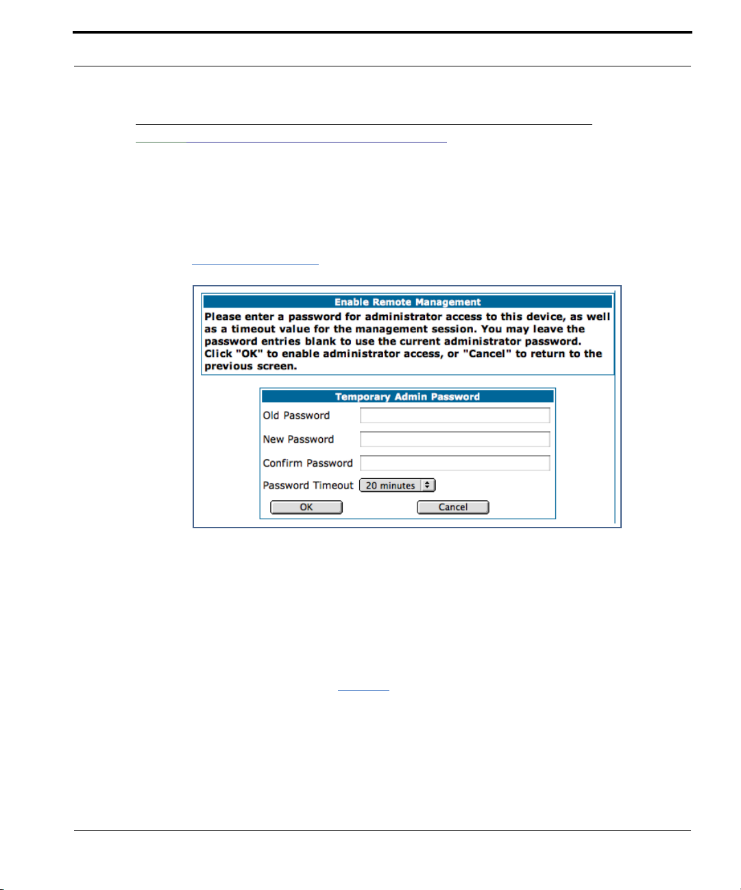
Link: Enable Remote Management
This link allows you to authorize a remotely-located person, such as a support technician,
to directly access your Netopia Gateway. This is useful for fixing configuration problems
when you need expert help. You can limit the amount of time such a person will have
access to your Gateway. This will prevent unauthorized individuals from gaining access
after the time limit has expired.
Click the
Since you’ve already has entered an Admin password, you can use that Admin password or
enter a new password. If you enter a new password, it becomes the temporar y Admin password. After the time-out period has expired, the Admin password rever ts to the original
Admin password you entered.
Enter a temporary password for the person you want to authorize, and confirm it by typing it
again. You can select a time-out period for this password, from 5 to 30 minutes, from the
pull-down menu. Be sure to tell the authorized person what the password is, and for how
long the time-out is set. Click the
Enable Rmt Mgmt
link. The Enable Remote Management page appears.
Submit
button.
31
Page 32

Link: Expert Mode
Most users will find that the basic Quickstart configuration is all that they ever need to use.
Some users, however, may want to do more advanced configuration. The Netopia Gateway
has many advanced features that can be accessed and configured through the Exper t
Mode pages.
Click on the
You should carefully consider any configuration changes you want to make, and be sure
that your service provider supports them.
Once you click the OK button you will be taken to the Expert Mode Home Page.
The Expert Mode Home Page is the main access point for configuring and managing the
advanced features of your Gateway. See “Expert Mode” on page 37 for information.
Expert Mode
link to display the Expert Mode Confirmation page.
Link: Update Firmware
(This link is not available on the 3342/3352 models, since firmware updates must be
upgraded via the USB host driver.)
32
Periodically, the embedded firmware in your Gateway may be updated to improve the operation or add new features. Your gateway includes its own onboard installation capability.
Your service provider may inform you when new firmware is available, or you can check for
yourself.
Page 33

Home Page - Basic Mode
Click the
If you click the
latest firmware revision. If a newer version is found, your firmware will be automatically
updated once you confirm the installation.
Update Firmware
Continue
button, the Gateway will check a remote Firmware Ser ver for the
link. The Firmware Update Confirmation page appears.
33
Page 34

Link: Factory Reset
In some cases, you may need to clear all the configuration settings and start over again to
program the Netopia Gateway. You can perform a factor y reset to do this.
Click on
Factory Reset
☛ NOTE:
Exercise caution before per forming a Factor y Reset. This will erase any configuration changes that you may have made and allow you to reprogram your
Gateway.
to reset the Gateway back to its original factory default settings.
34
Page 35

Home Page - Basic Mode
Link: Access Control Login
If you have configured Access Controls (see “Access Control” on page 89) an additional
Access Control Login
link
The Access Control Login link shows the login challenge page that access-controlled users
will encounter upon attempting to access the Internet.
displays.
• Username: Select a username from the drop-down list.
• Password: Enter your password for Access Control.
• Session Timeout: This field indicates web access session timeout. Entering a value of
zero hours and zero minutes will allow login for the full authorized time the user is
allowed. The user will be logged out upon reaching the end of their allowed time-of-day
settings.
35
Page 36

36
Page 37

Access the Expert Web Interface
CHAPTER 3 Expert Mode
Using the Expert Mode Web-based user interface for the Netopia 3300-series Gateway you
can configure, troubleshoot, and monitor the status of your Gateway.
Access the Expert Web Interface
Open the Web Connection
Once your Gateway is powered up, you can use any recent version of the best-known web
browsers such as Netscape Navigator or Microsoft Internet Explorer from any LAN-attached
PC or workstation. The procedure is:
1. Enter the name or IP address of your Netopia Gateway in the Web
browser's window and press Return.
For example, you would enter
2. If an administrator or user password has been assigned to the Netopia
Gateway, enter
word and click
The Basic Mode Home Page opens.
Admin
OK
.
http://192.168.1.254
or
User
as the username and the appropriate pass-
.
37
Page 38

3. Click on the
You are challenged to confirm your choice.
Click OK.
The Home Page opens in Expert Mode.
Expert Mode
link in the left-hand column of links.
38
Page 39

Access the Expert Web Interface
Home Page - Expert Mode
The Home Page is the summary page for your Netopia Gateway. The toolbar at the top provides links to controlling, configuring, and monitoring pages. Critical configuration and operational status is displayed in the center section.
Home Page - Information
The Home page’s center section contains a summary of the Gateway’s configuration settings and operational status.
Summary Information
Field Status and/or Description
General Information
Hardware Model number and summary specification
Serial Number Unique serial number, located on label attached to bottom of unit
Software Version Release and build number of running Netopia Operating System.
Product ID Refers to internal circuit board series; useful in determining which software
upgrade applies to your hardware type.
39
Page 40

Date & Time This is the current UTC time; blank if this is not available due to lack of a
network connection.
Breakwater Firewall Status of the Breakwater Firewall: ClearSailing, SilentRunning, or LANd-
Locked.
Safe Harbour SafeHarbour VPN IPsec Tunnel option (if installed): either On or Off.
WAN
Status Wide Area Network may be Waiting for DSL (or other waiting status), Up or
Down
Data Rate (Kbps) Once connected, displays DSL speed rate, Downstream and Upstream
Local Address IP address assigned to the WAN port.
Peer Address The IP address of the gateway to which the connection defaults. If doing
DHCP, this info will be acquired. If doing PPP, this info will be negotiated.
Connection Type May be either Instant On or Always On.
NAT On or Off. ON if using Network Address Translation to share the IP address
across many LAN users.
WAN Users Displays the number of users allotted and the total number available for
use.
LAN
IP Address Internal IP address of the Netopia Gateway.
Netmask Defines the IP subnet for the LAN
Default is 255.255.255.0 for a Class C device
DHCP Server On or Off. ON if using DHCP to get IP addresses for your LAN client
machines.
DHCP Leases A “lease” is held by each LAN client that has obtained an IP address through
DHCP.
Ethernet (or USB)
Status
Status of your Ethernet network connection (if supported). Up or Down.
40
Page 41

Toolbar
Toolbar
The toolbar is the dark blue bar at the top of the page containing the major navigation buttons. These buttons are available from almost ever y page, allowing you to move freely
about the site.
Home Configure Troubleshoot Security Install Restart Help
Quickstart System Status Passwords Install Keys
LAN Network Tools Firewall Install Software
WAN Diagnostics IPSec
Advanced Stateful Inspection
Packet Filter
Security Log
Navigating the Web Interface
Link: Breadcrumb Trail
The breadcrumb trail is built in the light brown area beneath the toolbar. As you navigate
down a path within the site, the trail is built from left to right. To return anywhere along the
path from which you came, click on one of the links.
41
Page 42

Restart
Button: Restart
The Restart button on the toolbar allows you to restart the Gateway at any time. You will be
prompted to confirm the restar t before any action is taken. The Restar t Confirmation message explains the consequences of and reasons for restarting the Gateway.
42
Page 43
Restart
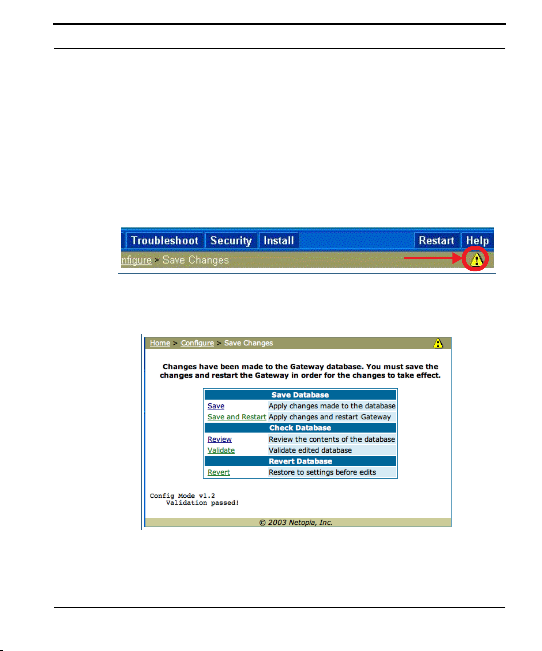
Link: Alert Symbol
The Alert symbol appears in the upper right corner if you make a database change; one in
which a change is made to the Gateway’s configuration. The Alert serves as a reminder
that you must Save the changes and Restart the Gateway before the change will take
effect. You can make many changes on various pages, and even leave the browser for up
to 5 minutes, but if the Gateway is restarted before the changes are applied, they will be
lost. When you click on the Alert symbol, the Save Changes page appears. Here you can
select various options to save or discard these changes.
If more than one Alert is triggered, you will need to take action to clear the first Alert before
you can see the second Alert.
43
Page 44
Help
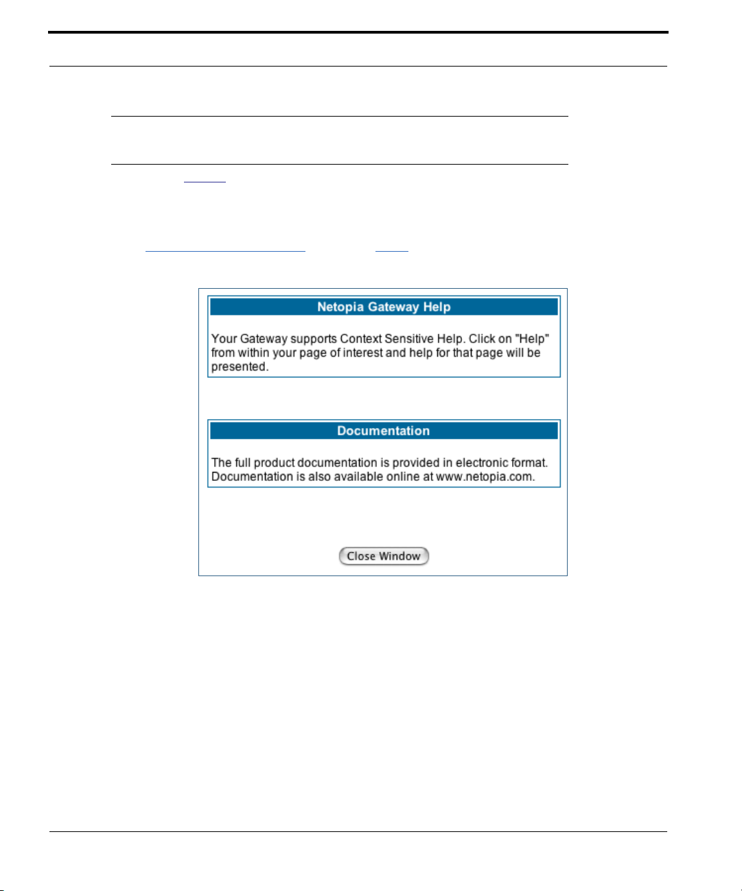
Button: Help
Context-sensitive Help is provided in your Gateway. The page shown here is displayed when
you are on the Home page or other transitional pages. To see a context help page example,
go to
Security -> Passwords
, then click
Help
.
44
Page 45

Configure
Configure
Button: Configure
The Configuration options are presented in the order of likelihood you will need to use
them. Quickstart is typically accessed during the hardware installation and initial configuration phase. Often, these settings should be changed only in accordance with infor-
mation from your Service Provider. LAN and WAN settings are available to fine-tune
your system. Advanced provides some special capabilities typically used for gaming or
small office environments, or where LAN-side servers are involved.
☛ This button will not be available if you log on as User.
Link: Quickstart
How to Use the Quickstart Page. Quickstart is normally used immediately after
the new hardware is installed. When you are first configuring your Gateway, Quickstart
appears first.
(Once you have configured your Gateway, logging on displays the Home page. Thereafter, if
you need to use Quickstart, choose it from the Expert Mode Configure menu.)
45
Page 46

Setup Your Gateway using a PPP Connection.
This example screen is the for a PPP Quickstart configuration. Your gateway authenticates with the Service Provider equipment using the ISP Username and Password. These
values are given to you by your Service Provider.
1. Enter your ISP Username and ISP Password.
2. Click
A brief message is displayed while the Gateway attempts to establish a connection.
Connect to the Internet
.
46
3. When the connection succeeds, your browser will display your Service
Provider’s home page.
If you encounter any problems connecting, refer to the chapters “Basic Troubleshooting”
on page 177 or “Advanced Troubleshooting” on page 187.
Page 47

Link: LAN
Configure
* Enable Interface: Enables all LAN-connected computers to share resources and to connect to the WAN. The Interface should always be enabled unless you are instructed to disable it by your Service Provider during troubleshooting.
* IP Address: The LAN IP Address of the Gateway. The IP Address you assign to your LAN
interface must not be used by another device on your LAN network.
* IP Netmask: Specifies the subnet mask for the TCP/IP network connected to the virtual
circuit. The subnet mask specifies which bits of the 32-bit binary IP address represent network information. The default subnet mask for most networks is 255.255.255.0 (Class C
subnet mask.)
* Restrictions: Specifies whether an administrator can open a Web Administrator or Telnet
connection to the Gateway over the LAN interface in order to monitor and configure the
Gateway. On the LAN Interface, you can enable or disable administrator access. By default,
administrative restrictions are turned of f, meaning an administrator can open a Web
Administrator or Telnet connection through the LAN Inter face.
47
Page 48

• Advanced: Clicking on the Advanced link displays the Advanced LAN IP Interface page.
• IGMP Forwarding: The default setting is Disabled. If you check this option, it will
enable Internet Group Management Protocol (IGMP) multicast for warding. IGMP allows
a router to determine which host groups have members on a given network segment.
• RIP Send Mode: Specifies whether the gateway should use Routing Information Proto-
col (RIP) broadcasts to advertise its routing tables to other routers on your network. You
may choose from the following protocols:
• RIP-1: Routing Information Protocol version 1
• RIP-2: RIP Version 2 is an extension of the original Routing Information Protocol (RIP-
1) that expands the amount of useful information in the RIP packets. While RIP-1 and
RIP-2 share the same basic algorithms, RIP-2 supports several new features, including
inclusion of subnet masks in RIP packets and implementation of multicasting instead of
broadcasting (which reduces the load on hosts which do not suppor t routing protocols.
• RIP-1 compatibility: Compatible with RIP version 1
• RIP-2 with MD5: MD5 authentication is an extension of RIP-2 that increases security
by requiring an authentication key when routes are adver tised.
• RIP MD5 Key: Secret password when using RIP-2 with MD5.
• RIP Receive Mode: Specifies whether the Gateway should use Routing Information Pro-
tocol (RIP) broadcasts to update its routing tables with information received from other
routers on your network. The protocol choices are the same as for the RIP send mode.
48
Page 49

Configure
• DHCP Server: Your Gateway can provide network configuration information to computers
on your LAN, using the Dynamic Host Configuration Protocol (DHCP).
If you already have a DHCP server on your LAN, you should turn this service off.
If you want the Gateway to provide this service, click the
choose Server, then configure the range of IP addresses that you would like the Gateway
to hand out to your computers.
You can also specify the length of time the computers can use the configuration information; DHCP calls this period the lease time.
Your Service Provider may, for certain services, want to provide configuration from its
DHCP servers to the computers on your LANs. In this case, the Gateway will relay the
DHCP requests from your computers to a DHCP ser ver in the Service Provider's network.
Click the relay-agent and enter the IP address of the Ser vice Provider's DHCP server in the
Server Address field. This address is furnished by the Service Provider.
Server Mode
pull-down menu,
☛ NOTE:
The relay-agent option only works when NAT is off and the Gateway is in router
mode.
49
Page 50

Wireless
If your Gateway is a wireless model (such as a 3347W) you can enable or disable the wireless LAN (WLAN) by clicking the
Wireless functionality is enabled by default.
If you uncheck the Enable Wireless checkbox, the Wireless Options are disabled, and the
Gateway will not provide or broadcast any wireless LAN ser vices.
Wireless
link.
50
SSID (Network ID): The SSID is preset to a number that is unique to your unit. You can
either leave it as is, or change it by entering a freeform name of up to 32 characters, for
example “Ed’s Wireless LAN”. On client PCs’ software, this might also be called the Net-
work Name. The SSID is used to identify this particular wireless LAN. Depending on their
operating system or client wireless card, users must either:
• select from a list of available wireless LANs that appear in a scanned list on their client
• or, if you are in Closed System Mode (see Enable Closed System Mode below), enter
this name on their clients in order to join this wireless LAN.
The pull-down menu for enabling Privacy offers four settings: WPA-802.1x, WPA-PSK,
WEP - Automatic, and Off - No Privacy.
Page 51

Configure
Privacy
• Off - No Privacy provides no encr yption on your wireless LAN data.
• WPA-802.1x provides RADIUS server authentication suppor t. It is only available if a
RADIUS server is configured. RADIUS server support is par t of the Hotspot feature key
(See “Wireless Hotspot Support (keyed feature)” on page 60.)
• WPA-PSK provides Wireless Protected Access, the most secure option for your wire-
less network. This mechanism provides the best data protection and access control.
The Pre Shared Key is a passphrase shared between the Router and the clients and is
used to generate dynamically changing keys. The passphrase can be 8-63 characters or
up to 64 hex characters. It is recommended to use at least 20 characters for best security.
51
Page 52

• WEP - Automatic is a passphrase generator. You enter a passphrase that you choose
in the Passphrase field. The passphrase can be any string of words or numbers.
You can provide a level of data security by enabling WEP (Wired Equivalent Privacy) for
encryption of network data. You can enable 40-, 128-, or 256-bit WEP Encryption
(depending on the capability of your client wireless card) for IP traffic on your LAN.
You select a single key for encryption of outbound traffic. The WEP-enabled client must
have an identical key of the same length, in the identical slot (1 – 4) as the Gateway, in
order to successfully receive and decr ypt the traffic. Similarly, the client also has a
‘default’ key that it uses to encrypt its transmissions. In order for the Gateway to
receive the client’s data, it must likewise have the identical key of the same length, in
the same slot. For simplicity, a Gateway and its clients need only enter, share, and use
the first key.
52
Click the
Click the Alert icon, and then the
Submit
button. The Alert icon appears.
Save and Restart
link.
Page 53

Advanced
If you click the
Configure
Advanced
link, the advanced 802.11 Wireless Settings page appears.
Note: This page displays different options depending on which form of Privacy you have
enabled.
53
Page 54

You can then configure:
Enable Multiple Wireless IDs. This feature allows you to add additional network
identifiers (SSIDs or Network Names) for your wireless network. To enable it, check the
checkbox. The screen expands to allow you to add additional Wireless IDs.
These additional Wireless IDs are “Closed System Mode” Wireless IDs (see below) that
will not be shown by a client scan, and therefore must be manually configured at the client.
In addition, wireless bridging between clients is disabled for all members of these additional network IDs. See Block Wireless Bridging below.
Default Channel: on which the network will broadcast. This is a frequency range within the
2.4Ghz band. Channel selection depends on government regulated radio frequencies that
vary from region to region. The widest range available is from 1 to 14. However, in North
America only 1 to 11 may be selected. Europe, France, Spain and Japan will differ. Channel
selection can have a significant impact on performance, depending on other wireless activity close to this Gateway. Channel selection is not necessary at the client computers; the
clients will scan the available channels seeking access points using the same SSID as the
client.
54
Enable Closed System Mode: If enabled, Closed System Mode hides the wireless network from the scanning features of wireless client computers. Unless both the wireless clients and the Gateway share the same SSID in Closed System mode, the Gateway’s
wireless LAN will not appear as an available network when scanned for by wireless-enabled
computers. Members of the Closed System WLAN must log onto the Gateway’s wireless
network with the identical SSID as that configured in the router.
Closed System mode is an ideal way to increase wireless security and to prevent casual
detection by unwanted neighbors, office users, or malicious users such as hackers.
Page 55

Configure
If you do not enable Closed System Mode, it is more convenient, but potentially less
secure, for clients to access your WLAN by scanning available access points. You must
decide based on your own network requirements.
About Closed System Mode
Enabling Closed System Mode on your wireless Gateway provides another level of security,
since your wireless LAN will no longer appear as an available access point to client PCs
that are casually scanning for one.
Your own wireless network clients, however, must log into the wireless LAN by using the
exact SSID of the Netopia Gateway.
In addition, if you have enabled WEP encryption on the Netopia Gateway, your network clients must also have WEP encryption enabled, and must have the same WEP encryption
key as the Netopia Gateway.
Once the Netopia Gateway is located by a client computer, by setting the client to a matching SSID, the client can connect immediately if WEP is not enabled. If WEP is enabled then
the client must also have WEP enabled and a matching WEP key.
Wireless client cards from dif ferent manufacturers and different operating systems accomplish connecting to a wireless LAN and enabling WEP in a variety of ways. Consult the documentation for your particular wireless card and/or operating system.
☛ NOTE:
While clients may also have a passphrase feature, these are vendor-specific
and may not necessarily create the same keys. You can passphrase generate
a set of keys on one, and manually enter them on the other to get around this.
Block Wireless Bridging: Check the checkbox to block wireless clients from communicating with other wireless clients on the LAN side of the Gateway.
55
Page 56

• On - Manual allows you to enter your own encr yption keys manually. This is a difficult
process, but only needs to be done once. Avoid the temptation to enter all the same
characters.
56
Encryption Key Size #1 – #4: Selects the length of each encryption key. The longer the
key, the stronger the encryption and the more dif ficult it is to break the encryption.
Encryption Key #1 – #4: The encryption keys. You enter keys using hexadecimal digits.
For 40/64bit encryption, you need ten digits; 26 digits for 128bit, and 58 digits for 256bit
WEP. Hexadecimal characters are 0 – 9, and a – f.
Examples:
• 40bit: 02468ACE02
• 128bit: 0123456789ABCDEF0123456789
Page 57

Configure
• 256bit: 592CA140F0A238B0C61AE162F592CA140F0A238B0C61AE162F21A09C
Use WEP encryption key (1 – 4) #: Specifies which key the Gateway will use to encrypt
transmitted traffic. The default is key #1.
You disable the wireless LAN by unchecking the Enable Wireless checkbox, clicking the
Submit
button, followed by the
Save and Restart
link.
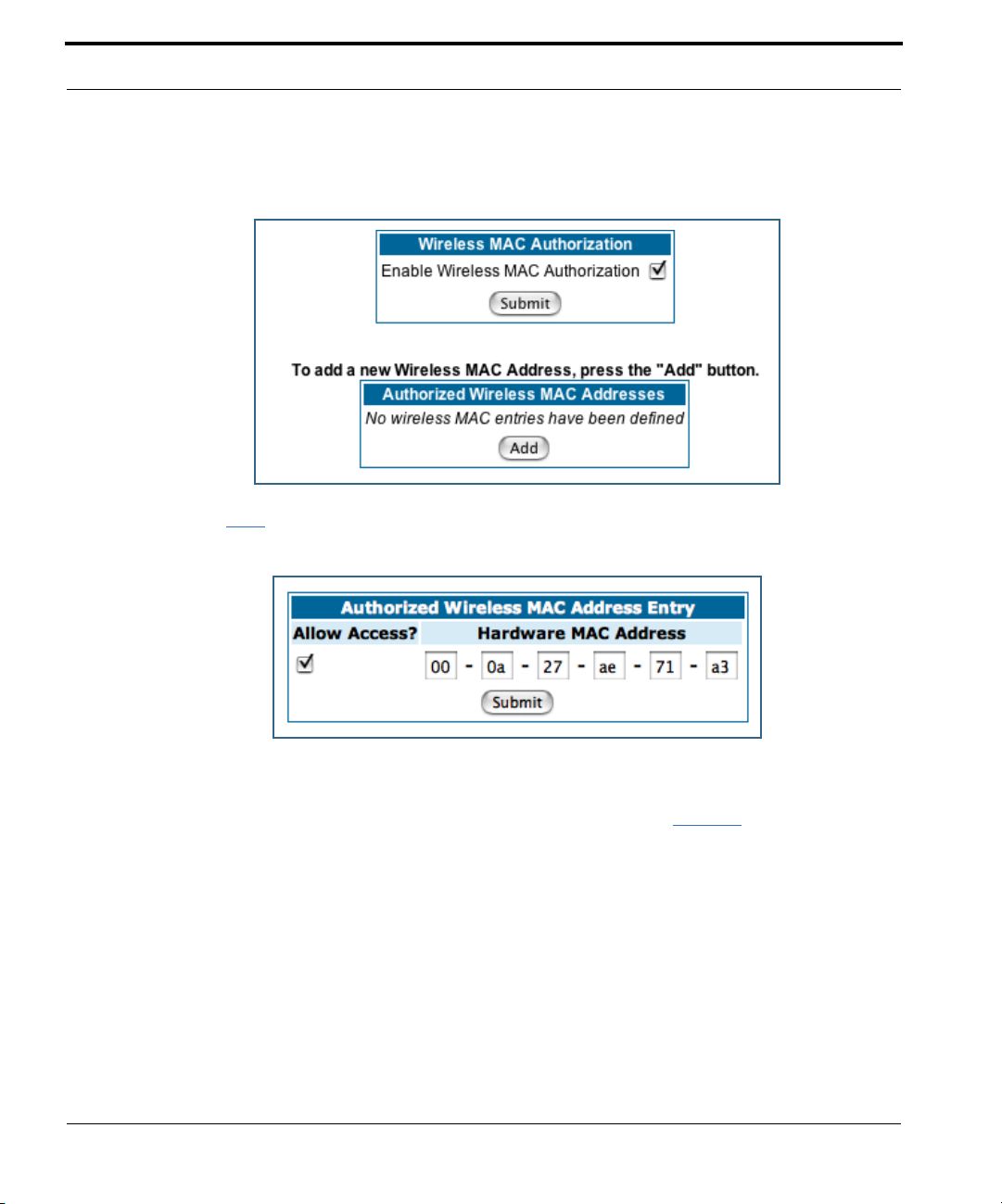
Wireless MAC Authorization
Wireless MAC Authorization allows you to specify which client PCs are allowed to join
the wireless LAN by specific hardware address. Once it is enabled, only entered MAC
addresses that have been set to Allow will be accepted onto the wireless LAN. All unlisted
addresses will be blocked, in addition to the listed addresses with Allow disabled.
To enable Wireless MAC Authentication, click the
When the Wireless MAC Authentication screen appears, check the Enable Wireless MAC
Authorization checkbox:
MAC Authorization
link.
57
Page 58
The screen expands as follows:
Click the
Enter the MAC (hardware) address of the client PC you want to authorize for access to your
wireless LAN. The Allow Access? checkbox is enabled by default. Unchecking this checkbox specifically denies access from this MAC address. Click the
Add
button. The Authorized Wireless MAC Address Entry screen appears.
Submit
button.
58
Page 59

Configure
Your entry will be added to a list of up to 32 authorized addresses as shown:
You can continue to
buttons.
After your first entry, the Alert icon will appear in the upper right corner of your
screen. When you are finished adding addresses to the list, click the Aler t icon, and Save
your changes and restart the Gateway.
Add, Edit
, or
Delete
addresses to the list by clicking the respective
59
Page 60

Wireless Hotspot Support (keyed feature)
Your wireless Gateway supports user name and password login, if you have the Wireless
Hotspot feature key installed. See “Install Keys” on page 173.
By enabling this feature you can limit wireless access through your Gateway by requiring
members of a list of Hotspot Users to log in with a username and password before entering your network. (User authentication is only required for WAN access and does not prevent LAN access.) The Hotspot Support key also adds RADIUS server suppor t in the
Advanced Configuration page. See “Use RADIUS Server” on page 63.
When this feature is enabled, users that are not on the Hotspot Users list (or who have
had their access disabled) will be prevented from accessing the WAN. Once you install the
feature key, the 802.11 Wireless Settings screen offers an additional link –
Setup
.
Hotspot
60
Click the
Hotspot Setup
Check the Enable Hotspots checkbox and click the
ton. The screen expands to allow you to configure your hotspot.
link. The Hotspot Setup page appears.
Submit
but-
Page 61

Configure
Click the
The Hotspot Users Entry screen appears.
Allow Access is checked by default (you can uncheck it to specifically deny access to a
particular user). Enter a Username and Password in the respective fields and click the
Submit button. The fields will clear and you can enter another Username and Password, up
to 16 users.
Configure Hotspot Users
link. The Hotspot Users screen appears.
To add a user, click the
Add
button.
61
Page 62
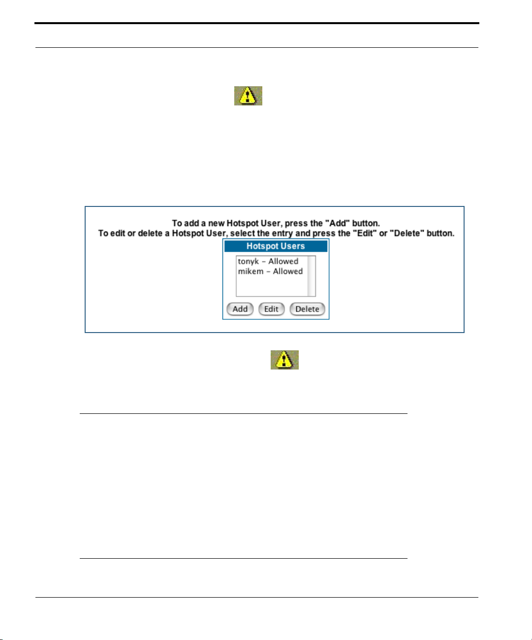
After your first entry, the Alert icon will appear in the upper right corner of your
screen. When you are finished adding users to the list, click the Alert icon, and Save your
changes and restart the Gateway.
If you need to Add, Edit (or Disallow), or Delete users later, return to the Hotspot User
Setup screen, where you can select users from the current Hotspot Users list for any of
these functions.
After you make any changes, the Alert icon will appear in the upper right corner of
your screen. When you are finished making your changes, click the Alert icon, Save your
changes and restart the Gateway.
62
☛ NOTE:
Optionally, if RADIUS servers are configured, a user may be verified by RADIUS
if the user does not exist locally.
The Hotspot Support key adds RADIUS server suppor t. See “Use RADIUS
Server” on page 63.
If they log in successfully, users will be forwarded to the original web destination that they tried to access. Users will simply encounter a username/password dialog box on the way to some web address they were going to, like
www.mumble.com.
Page 63

Configure
Post-login Redirect Page
If you check the Enable Post-login Redirect Page checkbox, the screen expands to per-
mit you to enter an Internet Web page URL. This can be any web address that you want
your users to encounter as your “home page” or “welcome page” before continuing to
access the Internet.
Enter a standard web address of the form www.my_redirect_page.com
Click the
Use RADIUS Server
See “Wireless Hotspot Support (keyed feature)” on page 60.
RADIUS servers allow external authentication of users by means of a remote authentication database. The remote authentication database is maintained by a Remote Authentication Dial-In User Service (RADIUS) server. In conjunction with Wireless User Authentication,
you can use a RADIUS server database to authenticate users seeking access to the wireless services, as well as the authorized user list maintained locally within the Gateway.
RADIUS server support is enabled when the Wireless Hotspot feature key is installed.
If you check the Use RADIUS Server checkbox, the screen expands to allow you to enter
your RADIUS server information.
Submit
button.
63
Page 64

• RADIUS Server Addr/Name: The default RADIUS ser ver name or IP address that you
want to use.
• RADIUS Server Secret: The RADIUS secret key used by this server. The shared secret
should have the same characteristics as a normal password.
• RADIUS Server Port: The por t on which the RADIUS server is listening, typically, the
default 1812.
64
Click the
You can also configure alternate RADIUS servers from the Advanced Network Configuration
page, by clicking the
Submit
button.
Advanced
link.
Page 65

Configure
The Advanced Network Configuration page appears.
You access the RADIUS Server configuration screen from the Advanced Network Configuration web page, by clicking the
RADIUS Server
link.
65
Page 66

The RADIUS Servers screen appears.
• RADIUS Server Addr/Name: The default RADIUS ser ver name or IP address that you
want to use.
• RADIUS Server Secret: The RADIUS secret key used by this server. The shared secret
should have the same characteristics as a normal password.
• Alt RADIUS Server Addr/Name: An alternate RADIUS server name or IP address to be
used if the primary server is unreachable.
• Alt RADIUS Server Secret: The secret key used by the alternate RADIUS server.
• Radius Server Port: This field specifies the por t on which the RADIUS server is listen-
ing. The default value is 1812.
66
When you are finished, click the
Submit
button.
Page 67

Link: WAN
Configure
WAN IP Interfaces
Your IP interfaces are listed. Click on an interface to configure it.
IP Gateway
Enable Gateway: You can configure the Gateway to send packets to a default gateway
if it does not know how to reach the destination host.
Interface Type: If you have PPPoE enabled, you can specify that packets destined for
unknown hosts will be sent to the gateway being used by the remote PPP peer. If you
select ip-address, you must enter the IP address of a host on a local or remote network
to receive the traffic.
Default Gateway: The IP Address of the default gateway.
Other WAN Options
PPPoE: You can enable or disable PPPoE. This link also allows configuration of NAT,
admin restrictions, PPPoE username/password, and connection type.
67
Page 68

ATM Circuits: You can configure the ATM circuits and the number of Sessions. The IP
Interface(s) should be reconfigured after making changes here.
Available Encapsulation types: Available Multiplexing types:
PPP over Ethernet (PPPoE) LLC/SNAP
PPP over ATM (PPPoA) VC muxed
RFC-1483 Bridged Ethernet
RFC-1483 Routed IP
None
68
Netopia Firmware Version 7 supports VPI/VCI autodetection by default. If VPI/VCI autodetection is enabled, the ATM Circuits page displays VPI/VCI = 0. If you configure a new
ATM VPI/VCI pair, upon saving and restarting, autodetection is disabled and only the
new VPI/VCI pair configuration will be enabled.
VPI/VCI Autodetection consists of eight static VPI/VCI pair configurations. These are 0/
35, 8/35, 0/32, 1/35, 8/32, 1/1, 1/32, 2/32. These eight VPI/VCI pairs will be created if the Gateway is configured for autodetection. the Gateway does not establish a
circuit using any of these preconfigured VPI/VCI pairs, then you can manually enter a
VPI/VCI pair in the ATM Circuits page.
ATM Traffic Shaping: You can prioritize delay-sensitive data by configuring the Quality
of Service (QoS) characteristics of the virtual circuit. Click the
ATM Traffic Shaping
link.
Page 69

Configure
You can choose UBR (Unspecified Bit Rate), CBR (Constant Bit Rate), or VBR (Variable
Bit Rate) from the pull-down menu and set the Peak Cell Rate (PCR) in the editable field.
UBR (Unspecified Bit Rate) guarantees no minimum transmission rate. Cells are
transmitted on a “best effort” basis. However, there is a cap on the maximum transmission rate for UBR VCs. In a practical situation:
• UBR VCs should be transmitted at a priority lower than CBR.
• Bandwidth should be shared equally among UBR VCs.
UBR applications are non-real-time traffic such as IP data traffic.
CBR (Constant Bit Rate) guarantees a certain transmission rate (although the appli-
cation may underutilize this bandwidth). A Peak Cell Rate (PCR) characterizes CBR. CBR
is most suited for real time applications such as real time voice / video, although it can
be used for other applications.
VBR (Variable Bit Rate) This class is characterized by:
• a Peak Cell Rate (PCR), which is a temporary burst, not a sustained rate, and
• a Sustained Cell Rate (SCR),
• a Burst Tolerance (BT), specified in terms of Maximum Burst Size (MBS). The MBS
is the maximum number of cells that can be transmitted at the peak cell rate and
should be less than, or equal to the Peak Cell Rate, which should be less than, or equal
to the line rate.
VBR has two sub-classes:
a. VBR non-real-time (VBR-nrt): Typical applications are non-real-time traffic, such as IP
data traffic. This class yields a fair amount of Cell Delay Variation (CDV).
b. VBR real time (VBR-rt): Typical applications are real-time traffic, such as compressed
voice over IP and video conferencing. This class transmits cells with a more tightly
bounded Cell Delay Variation. The applications follow CBR.
69
Page 70

☛ Note:
The difference between VBR-rt and VBR-nr t is the tolerated Cell Delay Variation range and the provisioned Maximum Burst Size.
Class PCR SCR MBS Transmit Priority Comments
UBR X N/A N/A Low PCR is a cap
CBR X N/A N/A High PCR is a guaranteed rate
VBR X X X High PCR > SCR.
SCR is a guaranteed rate.
PCR is a cap.
70
Page 71

Configure
Link: Advanced
Selected Advanced options are discussed in the pages that follow. Many are self-explanatory or are dictated by your service provider.
The following are links under Configure -> Advanced:
Link: IP Static Routes
A static route identifies a manually configured pathway to a remote network. Unlike
dynamic routes, which are acquired and confirmed periodically from other routers, static
71
Page 72

routes do not time out. Consequently, static routes are useful when working with PPP,
since an intermittent PPP link may make maintenance of dynamic routes problematic.
You can configure as many as 32 static IP routes for the Gateway.
Link: IP Static ARP
Your Gateway maintains a dynamic Address Resolution Protocol (ARP) table to map IP
addresses to Ethernet (MAC) addresses. It populates this ARP table dynamically, by retrieving IP address/MAC address pairs only when it needs them. Optionally, you can define
static ARP entries to map IP addresses to their corresponding Ethernet MAC addresses.
Unlike dynamic ARP table entries, static ARP table entries do not time out. The IP address
cannot be 0.0.0.0. The Ethernet MAC address entr y is in nn-nn-nn-nn-nn-nn (hexadecimal)
format.
72
Page 73

Configure
Link: Pinholes
Pinholes allow you to transparently route selected types of network traffic, such as FTP
requests or HTTP (Web) connections, to a specific host behind the Gateway. Creating a pinhole allows access traffic originating from a remote connection (WAN) to be sent to the
internal computer (LAN) that is specified in the Pinhole page.
Pinholes are common for applications like multiplayer online games. Refer to software
manufacturer application documentation for specific traffic types and port numbers.
Configure Specific Pinholes. Planning for Your Pinholes. Determine if any
of the service applications that you want to provide on your LAN stations use TCP or UDP
protocols. If an application does, then you must configure a pinhole to implement por t forwarding. This is accessed from the Advanced -> Pinholes page.
Example: A LAN Requiring Three Pinholes . The procedure on the following
pages describes how you set up your NAT-enabled Netopia Gateway to support three separate applications. This requires passing three kinds of specific IP traffic through to your
LAN.
Application 1
and would like users on the Internet to have access to it. With NAT “On”, the only externally
visible IP address on your network is the Gateway’s WAN IP (supplied by your Service Provider). All traffic intended for that LAN Web server must be directed to that IP address.
Application 2
email for all of the LAN users.
Application 3
want this specific LAN station to be dedicated to games.
: You have a Web server located on your LAN behind your Netopia Gateway
: You want one of your LAN stations to act as the “central repository” for all
: One of your LAN stations is specially configured for game applications. You
73
Page 74

A sample table to plan the desired pinholes is:
WAN Traffic Type Protocol Pinhole Name
Web TCP my-webserver 192.168.1.1
Email TCP my-mailserver 192.168.1.2
Games UDP my-games 192.168.1.3
For this example, Internet protocols TCP and UDP must be passed through the NAT security
feature and the Gateway’s embedded Web (HTTP) port must be re-assigned by configuring
new settings on the Internal Servers page.
LAN Internal IP
Address
☛ TIPS for making Pinhole Entries:
1. If the port forwarding feature is required for Web services, ensure that the
embedded Web server’s port number is re-assigned PRIOR to any Pinhole
data entry.
2. Enter data for one Pinhole at a time.
3. Use a unique name for each Pinhole. If you choose a duplicate name, it will
overwrite the previous information without warning.
74
Page 75

Configure
A diagram of this LAN example is:
Internet
WAN
Ethernet
Interface
210.219.41.20
Gateway
my-webserver
192.168.1.1
LAN
Ethernet
Interface
NAT
Embedded
NAT Pinholes
Web Server
210.219.41.20:8100
You can also use the LAN-side address of the Gateway, 192.168.1.x:8100 to access the
web and 192.168.1.x:23 to access the telnet server.
my-mailserver
192.168.1.2
my-games
192.168.1.3
75
Page 76

Pinhole Configuration Procedure. Use the following steps:
1. From the
Servers
Since Port Forwarding is required for this example, the Netopia embedded Web server
is configured first.
Configure
link.
toolbar button ->
Advanced
link, select the
Internal
☛ NOTE:
The two text boxes, Web (HTTP) Server Port and Telnet Server Port, on this
page refer to the port numbers of the Netopia Gateway’s embedded admin-
istration ports.
To pass Web traffic through to your LAN station(s), select a Web (HTTP) Port number that is
greater than 1024. In this example, you choose 8100.
2. Type
8100
in the Web (HTTP) Server Port text box.
76
3. Click the
4. Click
Advanced
Submit
button.
. Select the
Pinholes
link to go to the Pinhole page.
Page 77
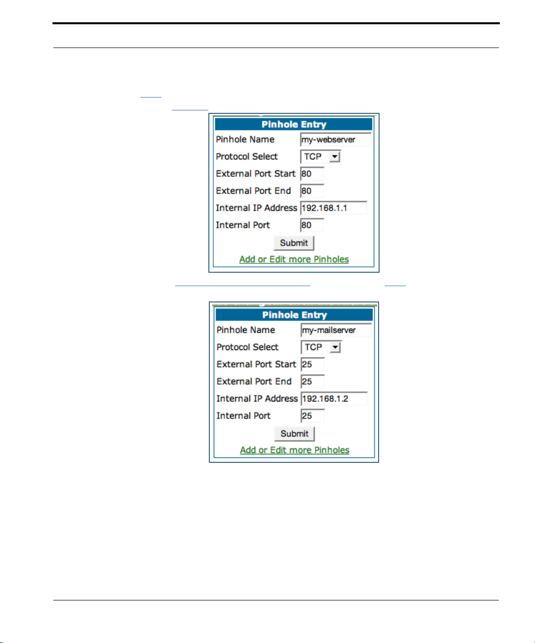
Configure
5. Click
6. Click on the
Add
. Type your specific data into the Pinhole Entries table of this
page. Click
Submit
.
Add or Edit more Pinholes
link. Click the
next Pinhole. Type the specific data for the second Pinhole.
Add
button. Add the
77
Page 78
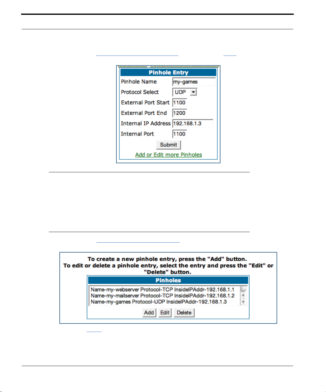
7. Click on the
next Pinhole. Type the specific data for the third Pinhole.
Add or Edit more Pinholes
link. Click the
☛ NOTE:
Note the following parameters for the “my-games” Pinhole:
1. The Protocol ID is UDP.
2. The external port is specified as a range.
3. The Internal port is specified as the lower range entry.
Add
button. Add the
78
8. Click on the
sure they are correct.
9. Click the
Add or Edit more Pinholes
Alert
button.
link. Review your entries to be
Page 79
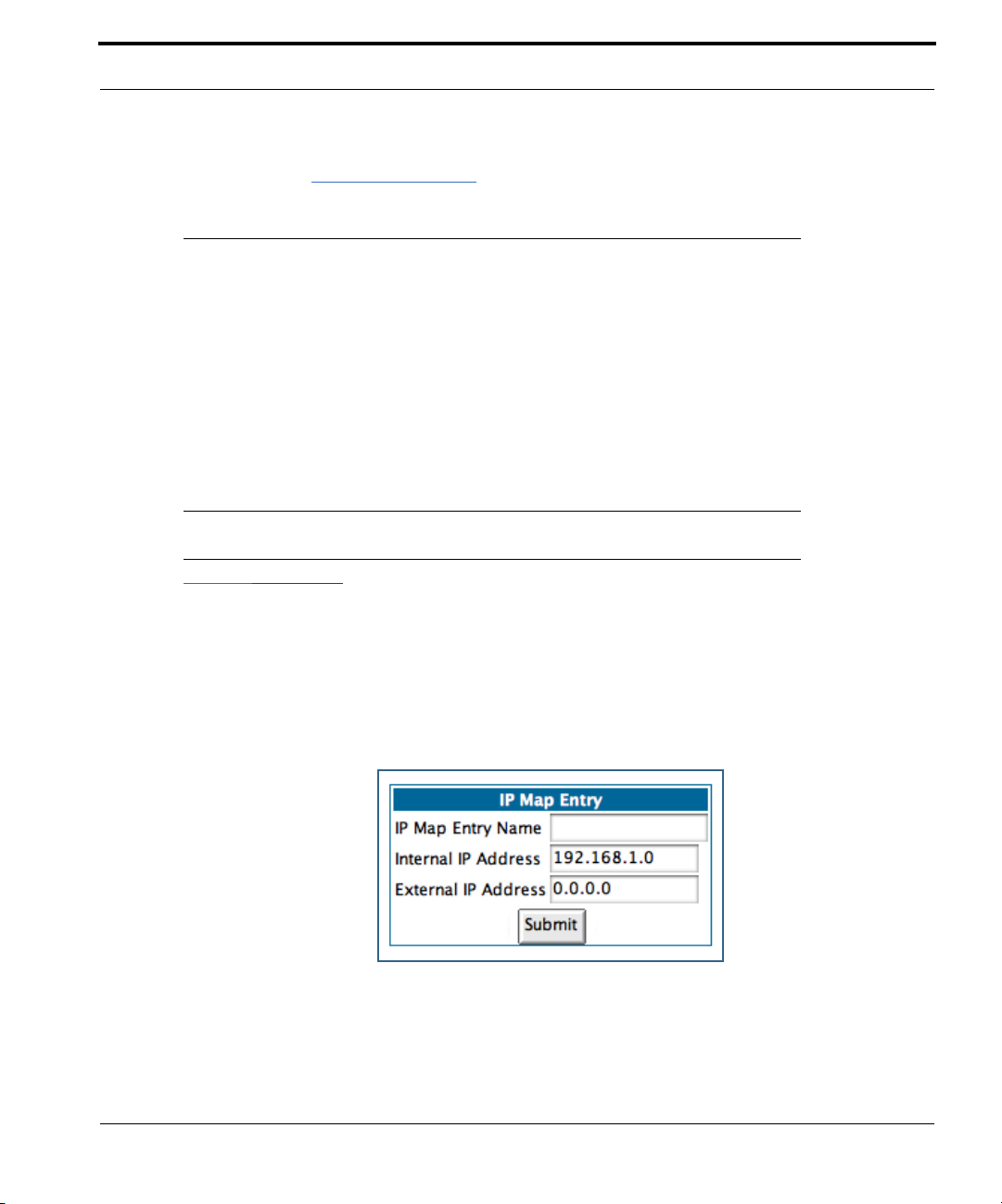
Configure
10. Select the
task and ensure that the parameters are properly saved.
Save and Restart
link to complete the entire Pinhole creation
☛ NOTE:
REMEMBER: When you have re-assigned the port address for the embedded
Web server, you can still access this facility.
Use the Gateway’s WAN address plus the new port number.
In this example it would be
<WAN Gateway address>:<new port number> or, in this case,
210.219.41.20:8100
You can also use the LAN-side address of the Gateway, 192.168.1.x:8100 to
access the web and 192.168.1.x:23 to access the telnet server.
Link: IPMaps
IPMaps supports one-to-one Network Address Translation (NAT) for IP addresses assigned
to servers, hosts, or specific computers on the LAN side of the Netopia Gateway.
A single static or dynamic (DHCP) WAN IP address must be assigned to support other
devices on the LAN. These devices utilize Netopia’s default NAT/PAT capabilities.
79
Page 80

Configure the IPMaps Feature
FAQs for the IPMaps Feature
Before configuring an example of an IPMaps-enabled network, review these frequently
asked questions.
What are IPMaps and how are they used? The IPMaps feature allows multi-
ple static WAN IP addresses to be assigned to the Netopia Gateway.
Static WAN IP addresses are used to support specific services, like a web ser ver, mail
server, or DNS server. This is accomplished by mapping a separate static WAN IP address
to a specific internal LAN IP address. All traffic arriving at the Gateway intended for the
static IP address is transferred to the internal device. All outbound traffic from the internal
device appears to originate from the static IP address.
Locally hosted servers are supported by a public IP address while LAN users behind the
NAT-enabled IP address are protected.
IPMaps is compatible with the use of NAT, with either a statically assigned IP address or
DHCP/PPP served IP address for the NAT table.
What types of servers are supported by IPMaps? IPMaps allows a Netopia
Gateway to support servers behind the Gateway, for example, web, mail, FTP, or DNS servers. VPN servers are not supported at this time.
80
Can I use IPMaps with my PPPoE or PPPoA connection? Yes. IPMaps
can be assigned to the WAN interface provided they are on the same subnet. Service
providers will need to ensure proper routing to all IP addresses assigned to your WAN interface.
Will IPMaps allow IP addresses from different subnets to be assigned
to my Gateway?
same subnet.
WAN IP addresses from different subnets are not supported.
IPMap will support statically assigned WAN IP addresses from the
Page 81

Configure
IPMaps Block Diagram
The following diagram shows the IPMaps principle in conjunction with existing Netopia NAT
operations:
Netopia Gateway
Static IP Addresses
for IPMaps Applications
143.137.50.37
143.137.50.36
143.137.50.35
Static IP Addresses
or
DHCP/PPP Served IP Address
for Netopia’s default NAT/PAT
Capabilities
WAN Interface LAN Interface
IPMaps:
One-to-One
Multiple Address Mapping
NAT/PAT Table
143.137.50.37
143.137.50.36
143.137.50.35
LAN stations with WAN IP traffic
forwarded by Netopia’s IPMaps
LAN stations with WAN IP traffic
forwarded by Netopia’s NAT function.
...
192.168.1.1
192.168.1.2
192.168.1.3
...
192.168.1.n
192.168.1.1
192.168.1.2
192.168.1.3
.
.
.
192.168.1.n
81
Page 82

Link: Default Server
This feature allows you to:
• Direct your Gateway to forward all externally initiated IP traffic (TCP and UDP protocols
only) to a default host on the LAN.
• Enable it for cer tain situations:
– Where you cannot anticipate what port number or packet protocol an in-bound application might use. For example, some network games select arbitrary port numbers
when a connection is opened.
– When you want all unsolicited traffic to go to a specific LAN host.
• Configure for IP Passthrough.
Configure a Default Server. This feature allows you to direct unsolicited or non-
specific traffic to a designated LAN station. With NAT “On” in the Gateway, these packets
normally would be discarded.
For instance, this could be application traffic where you don’t know (in advance) the port or
protocol that will be used. Some game applications fit this profile.
Use the following steps to setup a NAT default server to receive this information:
82
1. Select the
Server
2. From the pull-down menu, select
Configure
link.
toolbar button, then
Default-Server
Advanced
. The NAT Server IP
, then the
Default
Address field appears.
3. Determine the IP address of the LAN computer you have chosen to
receive the unexpected or unknown traffic.
Enter this address in the NAT Server IP Address field.
4. Click the
5. Click the
6. Click the
Submit
Alert
button.
button.
Save and Restart
link to confirm.
Page 83

Configure
Typical Network Diagram. A typical network using the NAT Default Server looks like
this:
Internet
Gateway
LAN STN #3
192.168.1.3
WAN
Ethernet
Interface
210.219.41.20
LAN
Ethernet
Interface
NAT
Embedded
Web Server
210.219.41.20
(Port 80 default)
You can also use the LAN-side address of the Gateway, 192.168.1.x to access the web
and telnet server.
NAT Default
Server
LAN STN #2
192.168.1.2
NAT protected
NAT Default Server
192.168.1.1
NAT Combination Application. Netopia’s NAT security feature allows you to con-
figure a sophisticated LAN layout that uses both the Pinhole and Default Server capabilities.
83
Page 84

With this topology, you configure the embedded administration ports as a first task, followed by the Pinholes and, finally, the NAT Default Server.
When using both NAT pinholes and NAT Default Server the Gateway works with the following rules (in sequence) to for ward traffic from the Internet to the LAN:
1. If the packet is a response to an existing connection created by outbound
traffic from a LAN PC, forward to that station.
2. If not, check for a match with a pinhole configuration and, if one is found,
forward the packet according to the pinhole rule.
3. If there’s no pinhole, the packet is forwarded to the Default Server.
IP-Passthrough. Your Gateway offers an IP passthrough feature. The IP passthrough
feature allows a single PC on the LAN to have the Gateway’s public address assigned to it.
It also provides PAT (NAPT) via the same public IP address for all other hosts on the private
LAN subnet. Using IP passthrough:
• The public WAN IP is used to provide IP address translation for private LAN computers.
• The public WAN IP is assigned and reused on a LAN computer.
• DHCP address serving can automatically ser ve the WAN IP address to a LAN computer.
When DHCP is used for addressing the designated passthrough PC, the acquired or
configured WAN address is passed to DHCP, which will dynamically configure a singleservable-address subnet, and reserve the address for the configured MAC address.
This dynamic subnet configuration is based on the local and remote WAN address and
subnet mask. If the WAN interface does not have a suitable subnet mask that is
usable, for example when using PPP or PPPoE, the DHCP subnet configuration will
default to a class C subnet mask.
84
• If you want to manually assign the WAN address to a LAN PC, do not check the DHCP
Enable checkbox.
• If you check the DHCP Enable checkbox, the screen expands.
Page 85

Configure
The Host Hardware Address field displays. Here you enter the MAC address of the designated IP-Passthrough computer.
• If this MAC address is not all zeroes, then it will use DHCP to set the LAN host's
address to the (configured or acquired) WAN IP address.
The MAC address must be six colon-delimited or dash-delimited sets of hex digits ('0' –
'FF').
• If the MAC address is all zeroes, then the LAN host will have to be configured manually.
Once configured, the passthrough host's DHCP leases will be shor tened to two minutes.
This allows for timely updates of the host's IP address, which will be a private IP address
before the WAN connection is established. After the WAN connection is established and
has an address, the passthrough host can renew its DHCP address binding to acquire the
WAN IP address.
A restriction. Since both the Gateway and the passthrough host will use the same IP
address, new sessions that conflict with existing sessions will be rejected by the Gateway.
For example, suppose you are a teleworker using an IPSec tunnel from the Gateway and
from the passthrough host. Both tunnels go to the same remote endpoint, such as the VPN
access concentrator at your employer’s office. In this case, the first one to start the IPSec
traffic will be allowed; the second one – since, from the WAN, it's indistinguishable – will
fail.
85
Page 86

Link: DNS
Your Service Provider may maintain a Domain Name server. If you have the information for
the DNS servers, enter it on the DNS page. If your Gateway is configured to use DHCP to
obtain its WAN IP address, the DNS information is automatically obtained from that same
DHCP Server.
86
Link: DHCP Server
Your Gateway can provide network configuration information to computers on your LAN,
using the Dynamic Host Configuration Protocol (DHCP).
If you already have a DHCP server on your LAN, you should turn this service off.
If you want the Gateway to provide this service, click the
then configure the range of IP addresses that you would like the Gateway to hand out to
your computers.
You can also specify the length of time the computers can use the configuration information; DHCP calls this period the lease time.
Server Mode
pull-down menu,
Page 87

Configure
Your Service Provider may, for certain services, want to provide configuration from its
DHCP servers to the computers on your LANs. In this case, the Gateway will relay the
DHCP requests from your computers to a DHCP ser ver in the Service Provider's network.
Click the relay-agent and enter the IP address of the Ser vice Provider's DHCP server in the
Server Address field. This address is furnished by the Service Provider.
☛ NOTE:
The relay-agent option only works when NAT is off and the Gateway is in router
mode.
Link: SNMP
The Simple Network Management Protocol (SNMP) lets a network administrator monitor
problems on a network by retrieving settings on remote network devices. The network
administrator typically runs an SNMP management station program on a local host to
obtain information from an SNMP agent. In this case, the Netopia Gateway is an SNMP
agent. Your Gateway supports SNMP-V1, with the exception of sets (read-only and traps),
and SNMP-V2.
You enter SNMP configuration information on this page.
Your network administrator furnishes the SNMP parameters.
87
Page 88

88
☛ WARNING:
SNMP presents you with a security issue. The community facility of
SNMP behaves somewhat like a password. The community “public” is a
well-known community name. It could be used to examine the configuration of your Gateway by your service provider or an uninvited
reviewer. The information can be read from the Gateway.
If you are strongly concerned about security, you may leave the “public”
community blank.
Page 89

Configure
Link: Access Control
Access Controls, also called “Parental Controls”, prevent designated users from accessing
certain types of undesirable Internet content. You can define levels of maturity of the users
on your network to filter out objectionable web content or communications from potentially
undesirable individuals on the Internet. You can also specify the time of day when users
may (or may not) access the Internet. Once Access Control is enabled on a WAN link, all
relevant traffic passing through the WAN link will be monitored for violations. All users will
need to sign on to Access Control before using Web, chat, or e-mail services.
When you click the
To enable Access Control, click the
Control screen appears.
Access Control
Check the Enable Access Control checkbox and click the
Submit
Return to the Access Control configuration page by clicking
the
link, the Access Control configuration page appears.
PPP over Ethernet vcc1
button.
Access Control
link in the Breadcrumb Trail.
link. The Enable Access
Click the
Setup
link in Access Control Options. The Manage Users screen appears.
89
Page 90

Click the
appears.
here
link. The Add New User screen
Here you can add the names and
passwords of authorized users, and
set their “Maturity Level” from the
pull-down menu. Available maturity
levels are Child, Youth, Mature,
and Adult. Click the
The Time of Day Settings screen
appears. Maturity Level only affects
Time of Day Settings.
Next
button.
90
Here you can specify the time of day, day(s) of the week, and whether this user will be permitted or blocked from accessing the Internet at the specified times and days. If you need
Page 91

Configure
to correct the Date and Time settings of your Gateway, you can go directly to the Time
here
Zone screen by clicking the
link at the top of the page.
When you have finished setting up the criteria for this user, click the
After you have added your users and configured their access control settings, you can
return to the Access Control pages at any time to add more users, edit existing ones, or
delete them.
To edit a user’s access control settings, click the
Edit Profile
The Edit User Profiles screen appears.
link for that user.
Add User
button.
• Manage Users – returns you to the previous screen.
• User Profile – takes you to the User Profile screen where you can change the user’s
password or maturity level setting, and time of day usage settings.
91
Page 92

• Web Filter Profile – takes you to the Web Filter Profile screen where you can filter the
websites accessible to this user.
• Chat Filter Profile – takes you to the Chat Filter Profile screen where you can specify
allowable chat partners for this user.
• Email Filter Profile – takes you to the Email Filter Profile screen where you can specify
allowable email partners for this user.
• Delete User Profile – allows you to delete this user.
Web Filter Profile
When you click the
Web Filter Profile
link, the Block/Allow Websites screen appears.
The Web Filter Profile allows you to Block or
Allow websites by keyword, for example, you
can block websites that feature the word
“gambling,” while allowing specific websites
that pertain to “statistics.” Once this profile
for this user is configured, the user will be prevented from accessing any blocked website.
You can set separate Web Filter Profiles for
each of your configured users. When you have
finished entering the information on this
screen, click the
Save
button.
92
Page 93

Configure
Chat Filter Profile
When you click the
Chat Filter Profile
link, the Chat Filtering screen appears.
Chat Filtering allows you to choose whether or not the specified user may engage in Internet instant messaging (chat) by means of the popular instant messaging protocols used by
America Online (AOL), Yahoo, Microsoft Network (MSN), or ICQ. If allowed, you can spec-
ify a limited number of individuals by “Screen Name” with whom this user can exchange
messages. For example, if you want to limit a child to exchanging messages only with other
family members, you can allow the messaging service(s), but restrict them to messages
only from approved users.
• Messaging Privileges Selection – Choose whether or not this user may use any
instant messaging (chat) service. The default privilege is May not use any instant Mes-
saging service. Click the appropriate radio button.
93
Page 94

• Messaging Services – If a chat ser vice is permitted, choose which one(s): AOL,
Yahoo!, MSN, or ICQ. You can choose more than one, but you must choose one at a
time. See below.
• Screen Names List Management –
• For each service, enter the screen name of the approved user in the New Screen
Name field and click the
Names List.
• Choose a different Messaging Service by clicking its radio button, enter another
approved user in the New Screen Name field, and click the
name will be added to the Screen Names List.
• When you have finished adding approved Screen Names to the list of permitted chat
partners for this user, click the
Add
button. The Screen name will be added to the Screen
Add
button. The Screen
Save
button.
94
Page 95
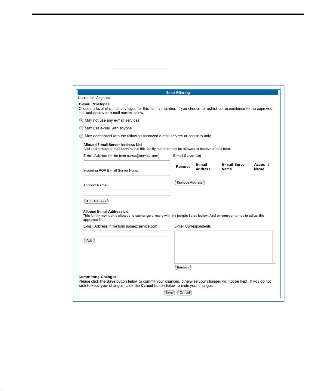
Configure
Email Filter Profile
When you click the
Email Filter Profile
link, the Email Filtering screen appears.
Email Filtering allows you to choose whether or not the specified user may send or receive
email. If allowed, you can specify limitations on the sources of email this user can receive.
You can limit email sources to an approved list of email servers, such as those used by the
family, or further, to an approved list of individuals, such as relatives, with whom this user
will be permitted to correspond.
95
Page 96

For example, if you want to limit a child to exchanging email only with other family members, you can allow the email server(s), but restrict them to messages only from approved
users.
• Email Privileges – Choose whether or not this user may use any e-mail ser vice. The
default privilege is May not use any e-mail service. Click the appropriate radio button.
• Allowed E-mail Server Address List –
• If e-mail service is permitted, enter the e-mail address of this user on this service in
the E-mail Address field. Example: Angel219@happyinternet.com.
• Enter the Incoming POP E-mail Server Name in the field provided. Example:
mailserver.happyinternet.com.
• Enter the user’s Account Name on this service in the field provided. Example:
Angel219.
• Click the
E-mail Server List. If this user has multiple e-mail accounts, repeat the previous steps
to add all of their accounts to the E-mail Server List.
Add Address
button. The information will be added to the
• Allowed E-mail Address List –
• You can restrict e-mail correspondence with this user by creating an approved list of
correspondents, with whom e-mail may be exchanged. Enter the full E-mail Address of
the approved correspondent in the field provided. Example: UncleRalph@aol.com. Click
the
Add
button. The approved e-mail user will be added to the
E-mail Correspondents list.
• Repeat the previous step to add additional approved correspondents to the
E-mail Correspondents list.
• When you have finished adding approved e-mail addresses to the list of permitted correspondents for this user, click the
Save
button.
96
Page 97

Configure
Delete User Profile
When you click the
appears.
Delete User Profile
link, the Confirm Deletion of User screen
97
Page 98

Link: UPnP
Universal Plug and Play (UPnP™) is a set of protocols that allows a PC to automatically discover other UPnP devices (anything from an internet gateway device to a light switch),
retrieve an XML description of the device and its services, control the device, and subscribe to real-time event notification.
By default, UPnP is enabled on the Netopia Gateway.
For Windows XP users, the automatic discovery feature places an
icon representing the Netopia Gateway automatically in the “My
Network Places” folder. Double-clicking this icon opens the Gateway’s web UI.
PCs using UPnP can retrieve the Gateway’s WAN IP address, and automatically create NAT
port maps. This means that applications that support UPnP, and are used with a UPnPenabled Netopia Gateway, will not need application layer gateway support on the Netopia
Gateway to work through NAT.
You can disable UPnP, if you are not using any UPnP devices or applications.
98
• Uncheck the
UPnP Enabled
checkbox, and click the
Submit
button.
• The Aler t icon will appear in the upper right corner of the web page. Click the Aler t icon,
and when prompted, click the
Save and Restart
link.
Page 99

Configure
Link: Advanced -> Ethernet Bridge
The Netopia Gateway can be used as a bridge, rather than a router. A bridge is a device
that joins two networks. As an Internet access device, a bridge connects the home computer directly to the service provider’s network equipment with no intervening routing functionality, such as Network Address Translation. Your home computer becomes just another
address on the service provider’s network. In a DSL connection, the bridge serves simply
to convey the digital data information back and for th over your telephone lines in a form
that keeps it separate from your voice telephone signals.
If your service provider’s network is set up to provide your Internet connectivity via bridge
mode, you can set your Netopia Gateway to be compatible.
Bridges let you join two networks, so that they appear to be part of the same physical network. As a bridge for protocols other than TCP/IP, your Gateway keeps track of as many as
512 MAC (Media Access Control) addresses, each of which uniquely identifies an individual
host on a network. Your Gateway uses this bridging table to identify which hosts are accessible through which of its network interfaces. The bridging table contains the MAC address
of each packet it sees, along with the interface over which it received the packet. Over
time, the Gateway learns which hosts are available through its WAN port and/or its LAN
port.
When configured in Bridge Mode, the Netopia will act as a pass-through device and allow
the workstations on your LAN to have public addresses directly on the internet.
☛ NOTE:
In this mode the Netopia is providing NO firewall protection as is afforded by
NAT. Also, only the workstations that have a public address can access the
internet. This can be useful if you have multiple static public IPs on the LAN.
Configuring for Bridge Mode
1. Browse into the Netopia Gateway’s web interface.
2. Click on the
3. Click on the
Configure
LAN
link.
button in the upper Menu bar.
99
Page 100
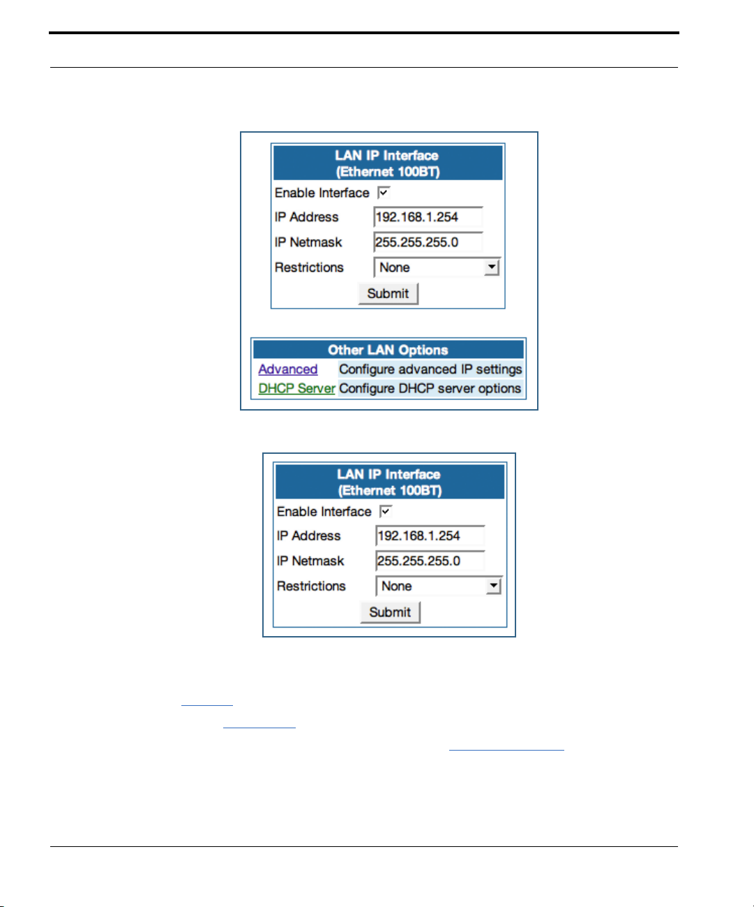
The LAN page appears.
4. In the box titled LAN IP Interface (Ethernet 100BT):
100
a. Check the Enable Interface selection.
*Make note of the Ethernet IP Address and subnet mask.
You can use this address to access the router in the future.
b. Click
5. Click on the
6. Under the heading of Services, click on the
Submit
Advanced
.
link in the left-hand links toolbar.
Ethernet Bridge
link.
 Loading...