

Page 1
NNNNeeeettttooooppppiiiiaa
aa
®®
®®
FFFFiiiirrrrmmmmwwwwaaaarrrreeee UUUUsssseeeerrrr GGGGuuuuiiiiddddee
ee
3333333300000000----EEEENNNNTTTT EEEEnnnntttteeeerrrrpppprrrriiiisssseeee SSSSeeeerrrriiiieeeess
NNNNeeeettttooooppppiiiiaaaa FFFFiiiirrrrmmmmwwwwaaaarrrreeee VVVVeeeerrrrssssiiiioooonnnn 8888....44
ss
44
Page 2

Copyright
Copyright© 2004, Netopia, Inc. Netopia and the Netopia logo are registered trademarks
belonging to Netopia, Inc., registered U.S. Patent and Trademark Office. Broadband Without
Boundaries and 3-D Reach are trademarks belonging to Netopia, Inc. All other trademarks
are the proper ty of their respective owners. All rights reser ved.
Netopia, Inc.
6001 Shellmound Street
Emeryville, CA 94608
U.S.A.
Part Number
Netopia part number 6161196-00-01
Page 3

CCCCoooonnnntttteeeennnnttttss
ss
Contents iii
Chapter 1 — Introduction.......................................................... 1-1
What’s New in 8.4 ......................................................... 1-1
Telnet-based Management.............................................. 1-2
Netopia Telnet Menus .................................................... 1-2
Netopia Models ............................................................. 1-3
Screen differences .............................................. 1-3
Connecting through a Telnet Session............................... 1-3
Configuring Telnet software................................... 1-4
Navigating through the Telnet Screens............................. 1-4
G
Chapter 2 — WAN and System Configuration .............................2-1
WAN Configuration ......................................................... 2-1
WAN Ethernet Configuration screen ....................... 2-2
ADSL Line Configuration screen ............................ 2-4
Creating a New Connection Profile................................... 2-9
Advanced Connection Options....................................... 2-14
Configuration Changes Reset WAN Connection..... 2-14
Scheduled Connections...................................... 2-15
Backup Configuration ......................................... 2-20
Priority Queuing (TOS bit).................................... 2-20
System Configuration Screens ...................................... 2-22
System configuration features............................. 2-22
IP Setup............................................................ 2-23
Filter Sets ......................................................... 2-23
IP Address Serving............................................. 2-23
Network Address Translation (NAT)...................... 2-23
Stateful Inspection............................................. 2-23
Date and time ................................................... 2-29
Wireless configuration ........................................ 2-30
SNMP (Simple Network Management Protocol)..... 2-36
Security............................................................. 2-36
Upgrade Feature Set .......................................... 2-36
Change Device to a Bridge.................................. 2-37
Page 4

iv
Firmware User Guide
Logging ............................................................. 2-38
Chapter 3 — Multiple Network Address Translation ...................3-1
Overview ....................................................................... 3-1
Features ............................................................. 3-2
Supported traffic ................................................. 3-5
Support for AOL Instant Messenger (AIM) File
Transfer .............................................................. 3-5
Support for Yahoo Messenger............................... 3-6
MultiNAT Configuration ................................................... 3-6
Easy Setup Profile configuration ............................ 3-6
Server Lists and Dynamic NAT configuration........... 3-7
IP setup .............................................................. 3-7
Modifying map lists............................................ 3-12
Adding Server Lists...................................................... 3-15
Modifying server lists ......................................... 3-17
Deleting a server ............................................... 3-19
Binding Map Lists and Server Lists ............................... 3-21
IP profile parameters.......................................... 3-21
IP Parameters (WAN Default Profile) .................... 3-23
NAT Associations......................................................... 3-25
IP Passthrough ............................................................ 3-27
MultiNAT Configuration Example.................................... 3-31
Chapter 4 — Virtual Private Networks (VPNs)............................4-1
Overview ....................................................................... 4-1
About PPTP Tunnels ....................................................... 4-4
PPTP configuration ............................................... 4-4
About IPsec Tunnels....................................................... 4-7
About L2TP Tunnels ....................................................... 4-8
L2TP configuration ............................................... 4-8
About GRE Tunnels ...................................................... 4-11
VPN force-all...................................................... 4-14
About ATMP Tunnels..................................................... 4-15
Page 5

Contents v
ATMP configuration ............................................ 4-15
Encryption Support ...................................................... 4-17
MS-CHAP V2 and 128-bit strong encryption ......... 4-18
ATMP/PPTP Default Profile............................................ 4-18
VPN QuickView ............................................................ 4-20
Dial-Up Networking for VPN ........................................... 4-21
Installing Dial-Up Networking............................... 4-21
Creating a new Dial-Up Networking profile ............ 4-22
Configuring a Dial-Up Networking profile............... 4-23
Connecting using Dial-Up Networking................... 4-24
Allowing VPNs through a Firewall ................................... 4-24
PPTP example.................................................... 4-26
ATMP example................................................... 4-28
Windows Networking Broadcasts................................... 4-31
Chapter 5 — Internet Key Exchange (IKE) IPsec
Key Management for VPNs ...................................5-1
Overview ....................................................................... 5-1
Internet Key Exchange (IKE) Configuration........................ 5-2
Adding an IKE Phase 1 Profile ............................... 5-4
Changing an IKE Phase 1 Profile ........................... 5-7
Key Management........................................................... 5-8
Advanced IPsec Options ..................................... 5-11
IPsec WAN Configuration Screens ................................. 5-18
IPsec Manual Key Entry................................................ 5-19
VPN Quickview................................................... 5-20
WAN Event History Error Reporting ...................... 5-21
G
Chapter 6 — IP Setup ............................................................... 6-1
IP Setup........................................................................ 6-2
IP subnets........................................................... 6-4
Static routes ....................................................... 6-6
RIP-2 MD5 Authentication............................................. 6-10
Overview ........................................................... 6-10
Page 6

vi
Firmware User Guide
Authentication configuration................................ 6-10
Connection Profiles and Default Profile ................ 6-15
IP Address Serving ...................................................... 6-17
IP Address Pools................................................ 6-20
DHCP NetBIOS Options ...................................... 6-21
More Address Ser ving Options...................................... 6-23
Configuring the IP Address Server options ........... 6-24
DHCP Relay Agent........................................................ 6-28
Connection Profiles ...................................................... 6-30
Multicast Forwarding.................................................... 6-33
Chapter 7 — Line Backup .........................................................7-1
Configuring Backup ........................................................ 7-1
Connection Profiles ........................................................ 7-2
IP Setup.............................................................. 7-7
WAN Configuration ......................................................... 7-8
Backup Configuration screen .............................. 7-10
Using Scheduled Connections with Backup .................... 7-12
Backup Default Gateway............................................... 7-14
Backup Configuration screen .............................. 7-14
IP Setup screen ................................................. 7-16
Backup Management/Statistics.................................... 7-17
QuickView ................................................................... 7-18
Chapter 8 — Monitoring Tools ................................................... 8-1
Quick View Status Overview............................................ 8-1
General status..................................................... 8-2
Current status ..................................................... 8-3
Status lights........................................................ 8-3
Statistics & Logs ........................................................... 8-4
Event Histories .............................................................. 8-4
IP Routing Table............................................................. 8-7
General Statistics .......................................................... 8-7
System Information........................................................ 8-9
Page 7

Contents vii
Simple Network Management Protocol (SNMP)............... 8-10
The SNMP Setup screen..................................... 8-11
SNMP traps....................................................... 8-12
Chapter 9 — Security ...............................................................9-1
Suggested Security Measures......................................... 9-1
Telnet Tiered Access – Two Password Levels ................... 9-2
UPnP Support...................................................... 9-2
Superuser configuration ....................................... 9-3
Limited user configuration .................................... 9-4
Advanced Security Options ................................... 9-6
User access password ......................................... 9-8
User menu differences......................................... 9-9
Telnet Access .............................................................. 9-16
About Filters and Filter Sets.......................................... 9-17
What’s a filter and what’s a filter set? ................. 9-17
How filter sets work ........................................... 9-17
How individual filters work .................................. 9-18
Design guidelines .............................................. 9-23
Working with IP Filters and Filter Sets............................ 9-24
Adding a filter set............................................... 9-25
Deleting a filter set ............................................ 9-29
A sample filter set.............................................. 9-29
Policy-based Routing using Filtersets............................. 9-32
TOS field matching............................................. 9-33
Firewall Tutorial ........................................................... 9-35
General firewall terms ........................................ 9-35
Basic IP packet components............................... 9-35
Basic protocol types........................................... 9-35
Firewall design rules .......................................... 9-36
Filter basics....................................................... 9-38
Example filters................................................... 9-39
Configuration Management ........................................... 9-42
G
Page 8

viii
Firmware User Guide
TFTP ................................................................. 9-44
Chapter 10 — Utilities and Diagnostics ...................................10-1
Ping ............................................................................ 10-2
Trace Route................................................................. 10-4
Telnet Client ................................................................ 10-5
Factory Defaults .......................................................... 10-6
Transferring Configuration and Firmware Files with TFTP.. 10-6
Updating firmware .............................................. 10-7
Downloading configuration files ........................... 10-7
Uploading configuration files ............................... 10-8
Restarting the System ................................................. 10-8
Appendix A — Troubleshooting.................................................. A-1
Configuration Problems .................................................. A-1
Network problems................................................ A-2
How to Reset the Router to Factory Defaults.................... A-3
Power Outages .............................................................. A-3
Technical Support .......................................................... A-3
How to reach us .................................................. A-4
Appendix B — Understanding IP Addressing ..............................B-1
What is IP?.................................................................... B-1
About IP Addressing ....................................................... B-1
Subnets and subnet masks .................................. B-2
Example: Using subnets on a Class C IP internet ... B-3
Example: Working with a Class C subnet................ B-5
Distributing IP Addresses ............................................... B-5
Technical note on subnet masking ........................ B-6
Configuration ....................................................... B-7
Manually distributing IP addresses ........................ B-8
Using address serving.......................................... B-8
Tips and rules for distributing IP addresses ........... B-9
Nested IP Subnets....................................................... B-11
Page 9

Contents ix
Broadcasts.................................................................. B-14
Packet header types .......................................... B-14
Appendix C — Binary Conversion Table......................................C-1
Appendix D — Technical Specifications and Safety Information ..D-1
Description.................................................................... D-1
Power requirements ............................................. D-1
Environment ........................................................ D-1
Software and protocols ........................................ D-1
Agency approvals........................................................... D-2
North America ..................................................... D-2
International........................................................ D-2
Manufacturer’s Declaration of Conformance .................... D-3
Important Safety Instructions ......................................... D-4
FCC Part 68 Information................................................. D-5
FCC Requirements ............................................... D-5
FCC Statements .................................................. D-5
Electrical Safety Advisory ............................................... D-7
G
Index
Page 10

x
Firmware User Guide
Page 11

Introduction 1-1
CCCChhhhaaaapppptttteeeerrrr 11
IIIInnnnttttrrrroooodddduuuuccccttttiiiioooonn
This
Firmware User Guide
Your Netopia equipment offers advanced configuration features accessed through the Main Menu of the Telnet
configuration screen. This
security, monitoring, and configuration. This
Quickstart Guide
Guide
before reading this
11
and the
nn
covers the advanced features of the Netopia 3300-Series Router family.
Firmware User Guide
Getting Started Guide
Firmware User Guide
documents the advanced features, including advanced testing,
Firmware User Guide
. You should read the
.
should be used as a companion to the
Quickstart Guide
and the
Getting Started
What’s New in 8.4
New in Netopia Firmware Version 8.4 are the following features:
•
IPSec MTU Support
See “Advanced IPsec Options” on page 5-11.
•
TACACS+ Support
See “TACACS+ server authentication” on page 9-8.
•
GRE Tunneling Support
See “About GRE Tunnels” on page 4-11.
•
Session Initiation Protocol ALG support setting in the CLI.
(The SIP ALG supports only SIP over UDP, not TCP.)
See the
Command Line Interface Commands Reference
available on the Netopia website.
Page 12

1-2 Firmware User Guide
Telnet-based Management
Telnet-based management is a fast menu-driven interface for the capabilities built into the Netopia Firmware
Version 8.4. Telnet-based management provides access to a wide variety of features that the Router supports.
You can customize these features for your individual setup. This chapter describes how to access the
Telnet-based management screens. This section covers the following topics:
•
“Netopia Telnet Menus” on page 1-2
•
“Netopia Models” on page 1-3
•
“Connecting through a Telnet Session” on page 1-3
•
“
Navigating through the Telnet Screens” on page 1-4
Netopia Telnet Menus
Telnet-based management screens contain the main entry points to the Netopia Firmware Version 8.4
configuration and monitoring features. The entry points are displayed in the Main Menu shown below:
Netopia 3366 V 8.4
Easy Setup...
WAN Configuration...
System Configuration...
Utilities & Diagnostics...
Statistics & Logs...
Quick Menus...
Quick View...
•
The
Easy Setup
You can use Easy Setup to initially configure the Router directly through a Telnet session.
Easy Setup menus contain up to five descendant screens for viewing or altering these values. The number
of screens depends on whether you have optional features installed.
The
Quickstart Guide
•
The
WAN Configuration
Networks (VPNs) and default profile, creating or deleting additional connection profiles, and configuring or
reconfiguring the manner in which you may be using the Router to connect to more than one ser vice
menus display and permit changing the values contained in the default connection profile.
describes the Easy Setup menus to get you up and running quickly.
menu displays and permits changing your connection profile(s), Vir tual Private
Page 13

Introduction 1-3
provider or remote site. See “WAN Configuration,” beginning on page 2-1. See also Chapter 4, “Virtual
Private Networks (VPNs).”
•
The
System Configuration
• IP Setup • Filter Sets
• IP Address Serving • Network Address Translation (NAT)
• Date and Time • SNMP (Simple Network Management Protocol)
• Security • Upgrade Feature Set
• Change Device to a Bridge • Logging
and more. See “System Configuration Screens,” beginning on page 2-22.
•
The
Utilities & Diagnostics
the Router's behavior, as well as for updating the firmware and rebooting the system. See Chapter 10,
“Utilities and Diagnostics.”
•
The
Statistics & Logs
your Router, your network, and their history. See “Statistics & Logs,” beginning on page 8-4.
•
The
Quick Menus
menus that are accessed through the other menu entr y points.
•
The
Quick View
“Quick View Status Overview” on page 8-1.
screen is a shortcut entry point to a variety of the most commonly used configuration
menu displays at a glance current real-time operating information about your Router. See
menus display and permit changing:
menus provide a selection of the various tools for monitoring and diagnosing
menus display several sets of tables and device logs that show information about
Netopia Models
This
Firmware User Guide
this guide will only apply to a specific model.
covers all of the Netopia 3300-Series Router models. However some information in
Screen differences
Because different Netopia 3300-Series models offer many different features and interfaces, the options shown
on some screens in this
These differences are noted throughout the manual.
Firmware User Guide
may not appear on your own particular model’s Telnet screen.
Connecting through a Telnet Session
Features of the Netopia Firmware Version 8.4 can be configured through the Telnet screens.
Before you can access the console screens through Telnet, you must have:
•
A network connection locally to the Router or IP access to the Router.
•
Telnet software installed on the computer you will use to configure the Router
Page 14
1-4 Firmware User Guide
Configuring Telnet software
If you are configuring your device using a Telnet session, your computer must be running a Telnet software
program.
•
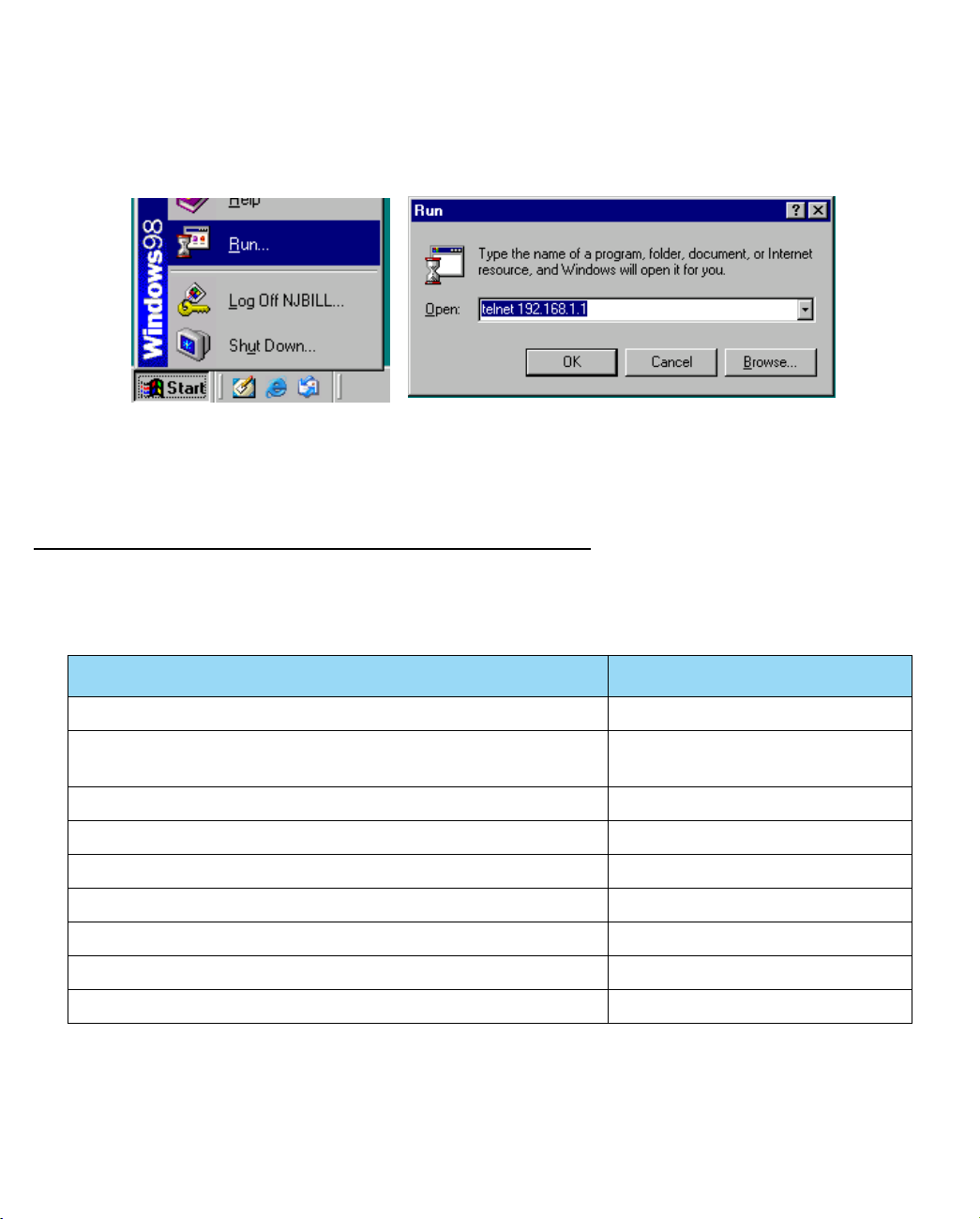
If you connect a PC with Microsoft Windows, you can use a Windows Telnet application or run Telnet from
the Start menu.
•
If you connect a Macintosh computer running Classic Mac OS, you can use the NCSA Telnet program
supplied on the Netopia CD. You install NCSA Telnet by dragging the application from the CD to your hard
disk.
Mac OS X users can use the Terminal application that comes with Mac OS X in the Utilities folder.
Navigating through the Telnet Screens
Use your keyboard to navigate the Netopia Firmware Version 8.4’s configuration screens, enter and edit
information, and make choices. The following table lists the keys to use to navigate through the Telnet screens.
To... Use These Keys...
Move through selectable items in a screen or pop-up menu Up, Down, Left, and Right Arrow
Set a change to a selected item or open a pop-up menu of
options for a selected item like entering an upgrade key
Change a toggle value (Yes/No, On/Off) Tab
Restore an entry or toggle value to its previous value Esc
Move one item up Up arrow or Control + K
Move one item down Down arrow or Control + O
Display a dump of the device event log Control + E
Display a dump of the WAN event log Control + F
Refresh the screen Control + L
Return or Enter
Page 15

Introduction 1-5
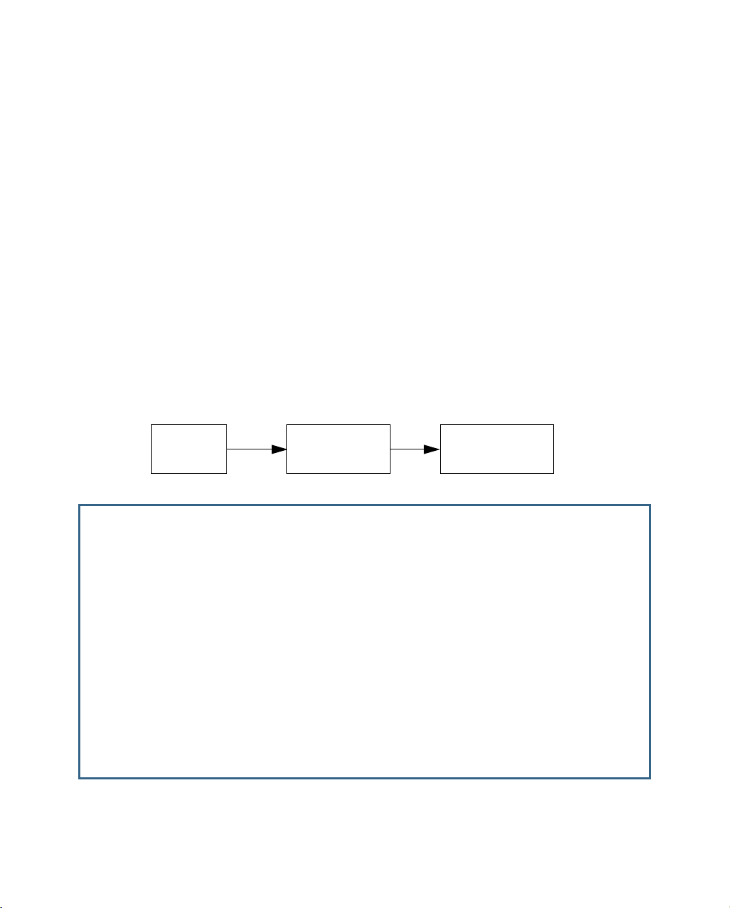
To help you find your way to particular screens, some sections in this guide begin with a graphical path guide
similar to the following example:
Main
Menu
This particular path guide shows how to get to the Network Protocols Setup screens. The path guide represents
these steps:
1. Beginning in the Main Menu, select
screen appears.
2. Select
To go back in this sequence of screens, use the Escape key.
IP Setup
and press Return. The IP Setup screen appears.
System Configuration
System
Configuration
IP Setup
and press Return. The System Configuration
Page 16

1-6 Firmware User Guide
Page 17

WAN and System Configuration 2-1
CCCChhhhaaaapppptttteeeerrrr 22
WWWWAAAANNNN aaaannnndddd SSSSyyyysssstttteeeemmmm CCCCoooonnnnffffiiiigggguuuurrrraaaattttiiiioooonn
This chapter describes how to use the Telnet-based management screens to access and configure advanced
features of your equipment. You can customize these features for your individual setup. These menus provide a
powerful method for experienced users to set up their Router’s connection profiles and system configuration.
This section covers the following topics:
•
“WAN Configuration” on page 2-1
•
“WAN Ethernet Configuration screen” on page 2-2
•
“ADSL Line Configuration screen” on page 2-4
•
“Creating a New Connection Profile” on page 2-9
•
“
Advanced Connection Options” on page 2-14
•
“Configuration Changes Reset WAN Connection” on page 2-14
• “Scheduled Connections” on page 2-15
• “Backup Configuration” on page 2-20
• “System Configuration Screens” on page 2-22
22
nn
• “System configuration features” on page 2-22
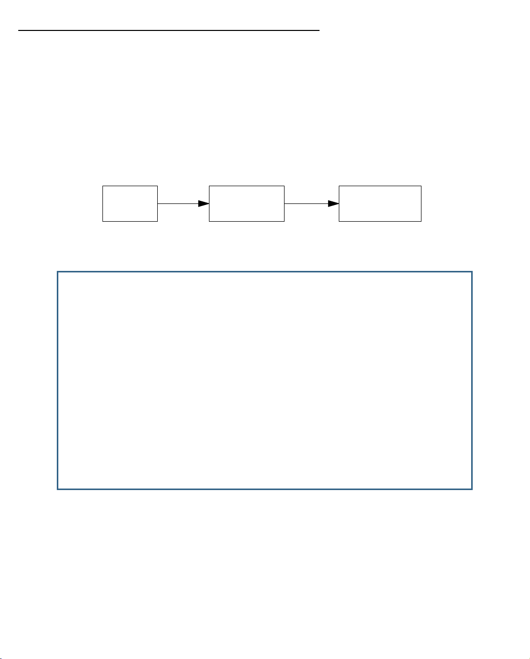
WAN Configuration
To configure your Wide Area Network (WAN) connection, navigate to the WAN Configuration screen from the Main
Menu and select WAN (Wide Area Network) Setup.
Main
Menu
The Line Configuration screen appears. The Line Configuration screen will be appropriate to the type of WAN
interface supported by your particular Router model.
WAN
Configuration
WAN
Setup
Page 18

2-2 Firmware User Guide
WAN Ethernet Configuration screen
The WAN Ethernet Configuration screen appears as follows:
WAN Ethernet Configuration
Address Translation Enabled: Yes
Local WAN IP Address: 0.0.0.0
NAT Map List... Easy-PAT List
NAT Server List... Easy-Servers
NAT Options...
Stateful Inspection Enabled: No
Filter Set...
Remove Filter Set
Enable PPP over Ethernet: Off
WAN Ethernet Speed Setting... Auto-Negotiation
Wan Ethernet MAC Address: 00:fc:de:fa:dd:02
DHCP Client Mode: Standards-Based
RIP Options...
Set up the basic IP attributes of your Ethernet Module in this screen.
• Address Translation Enabled allows you to specify whether or not the router performs Network Address
Translation (NAT) on the Ethernet WAN port. NAT is enabled by default.
• Local WAN IP Address allows you to manually configure an IP address for use on the Ethernet WAN port.
The value 0.0.0.0 indicates that the device will act as a DHCP client on the Ethernet WAN port and attempt
to acquire an address from a DHCP ser ver. By default, the router acts as a DHCP client on the Ethernet
WAN port.
• The Local WAN IP Mask field becomes visible if you specify a Local WAN IP Address. This allows you to
manually configure an IP subnet mask for use on the Ethernet WAN port. This item is visible only if you
have configured a non-zero Ethernet IP Address; other wise, the router obtains a subnet mask via DHCP.
• The NAT Map List and NAT Server List options are set to the defaults, Easy-PAT List and Easy-Servers.
These provide standard NAT mappings. For more advanced NAT configurations, see “Multiple Network
Address Translation” on page 3-1.
• NAT Options allows you to specify IP Passthrough, allowing a single PC on the LAN to have the router’s
public address assigned to it. See “IP Passthrough” on page 3-27.
• If you set Stateful Inspection Enabled to Yes , you can enable a security feature for computers on your LAN
when NAT is disabled. See “Stateful Inspection” on page 2-23.
• The Filter Set pop-up allows you to associate an IP filter set with the Ethernet WAN port. See “About Filters
and Filter Sets” on page 9-17.
• Remove Filter Set allows you to remove a previously associated filter set.
• Enable PPP over Ethernet is Off by default. If your ser vice provider uses PPPoE authentication toggle this
to On.
Page 19

WAN and System Configuration 2-3
• The WAN Ethernet Speed Setting is now configurable via a pop-up menu. Options are: Auto-Negotiation
(the default), 100 Mbps Full Duplex, 100 Mbps Half Duplex, 10 Mbps Full Duplex, and 10 Mbps Half
Duplex. This may be useful in mixed networks, where multiple routers have different ethernet speed
capability. If you want to maintain a single speed setting for compatibility with multiple routers on your LAN,
you can select a speed/duplex combination that all of your routers can match.
• The Wan Ethernet MAC Address is the hardware address of the Netopia device. Some service providers
require a specific MAC address as par t of their authentication process. In such a case, you can enter the
MAC address that your service provider requires. If your ser vice provider doesn’t use this method, you
don’t need to change this field.
• The DHCP Client Mode setting depends on the type of access concentrator equipment your service
provider uses. Most use Standards-Based. Alternatively, your provider may instruct you to select Copper
Mountain Specific.
• The RIP Options selection displays the WAN Ethernet RIP Parameters screen.
WAN Ethernet RIP Parameters
+----------------+
+----------------+
Receive RIP: | Off |
| v1 |
Transmit RIP: | v2 |
| Both |
+----------------+
• The Receive RIP pop-up menu controls the reception and transmission of Routing Information Protocol
(RIP) packets on the Ethernet WAN port. The default is Both.
The Transmit RIP pop-up menu is hidden if NAT is enabled.
Routing Information Protocol (RIP) is needed if there are IP routers on other segments of your Ethernet
network that the Netopia Firmware Version 8.4 needs to recognize. Set to “Both” (the default) the Netopia
Firmware Version 8.4 will accept information from either RIP v1 or v2 routers. Alternatively, select Receive
RIP and select v1 or v2 from the popup menu. With Receive RIP set to “v1,” the Netopia Router’s Ethernet
port will accept routing information provided by RIP packets from other routers that use the same subnet
mask. Set to “v2,” the Netopia Firmware Version 8.4 will accept routing information provided by RIP
packets from other routers that use different subnet masks.
Page 20

2-4 Firmware User Guide
If you want the Netopia Router to advertise its routing table to other routers via RIP, select Transmit RIP
and select v1, v2 (broadcast), or v2 (multicast) from the popup menu. With Transmit RIP v1 selected, the
Netopia Firmware Version 8.4 will generate RIP packets only to other RIP v1 routers. With Transmit RIP v2
(broadcast) selected, the Netopia Firmware Version 8.4 will generate RIP packets to all other hosts on the
network. With Transmit RIP v2 (multicast) selected, the Netopia Firmware Version 8.4 will generate RIP
packets only to other routers capable of recognizing RIP v2 packets.
ADSL Line Configuration screen
The ADSL Line Configuration screen is shown below:
ADSL Line Configuration
Circuit Type... Multimode
Trellis Coding Enabled: On
Signaling Mode... FDM
Fast Retrain Enabled: On
Wiring Type... AutoSense
Data Link Encapsulation... RFC1483
1. Select Circuit Type and from the pop-up menu choose the type of circuit to which you will be connecting:
Multimode, T1.413, G.dmt, or G.lite.
2. Select Trellis Coding Enabled. Toggle it to On (the default) or Off.
3. Select Signaling Mode and choose Echo Cancellation or FDM (the default).
4. If you selected Multimode Circuit Type, the Fast Retrain Enabled field appears. Toggle it to On (the default)
or Off.
5. The Wiring Type pop-up menu allows you to choose the type of copper pair wiring in use at your location.
Usually, the default AutoSense will detect the type and adjust itself accordingly. If you want to set it
yourself, and you know the type of wiring you have, choose either Tip/Ring (Inner Pair) or A/A1 (Outer Pair)
from the pop-up menu.
6. Select Data Link Encapsulation and press Return. The pop-up menu will offer you the choice of PPP or
RFC1483.
ATM Circuit Configuration
On ADSL WAN interfaces, the Asynchronous Transfer Mode (ATM) connection between the router and the
central office equipment (DSLAM) is divided logically into one or more virtual circuits (VCs). A virtual circuit may
be either a permanent vir tual circuit (PVC) or a switched vir tual circuit (SVC). Netopia Routers support PVCs.
Page 21
WAN and System Configuration 2-5
VCs are identified by a Virtual Path Identifier (VPI) and Virtual Channel Identifier (VCI). A VPI is an 8-bit value
between 0 and 255, inclusive, while a VCI is a 16-bit value between 0 and 65535, inclusive.
• Circuits support attributes in addition to their VPI and VCI values. When configuring a circuit, you can
specify an optional circuit name of up to 14 characters. The circuit name is used only to identify the circuit
for management purposes as a convenience to aid in selecting circuits from lists. The default circuit name
is “Circuit <n>”, where <n> is some number between one and eight corresponding to the circuit’s position
in the list of up to eight circuits.
• You can also individually enable or disable a circuit without deleting it. This is useful for temporarily
removing a circuit without losing the configured attributes.
• In order to function, each circuit must be bound to a Connection Profile or to the Default Profile. Among
other attributes, the profile binding specifies the IP addressing information for use on the circuit. Each
circuit must be bound to a distinct Connection Profile.
ATM VPI/VCI Autodetection. You can bind multiple circuits to the same Connection Profile. Netopia Firmware
Version 8.4 allows you to have a standard configuration that uses, for example, four VCs (0/35, 0/38, 8/35,
8/38) pointing to the same profile.
The unit will now automatically select the active VC on networks with a VPI/VCI of any of these four values
without any custom configuration of the unit. You must, however, manually create these VCs and associate
them with the profile you desire.
You configure Virtual Circuits in the Add/Change Circuit screen.
Main
Menu
ATM Circuits Configuration
Show/Change Circuit...
Add Circuit...
Delete Circuit...
WAN
Configuration
ATM Circuits
Configuration
7. To add a circuit, select Add Circuit and press Return. The Add Circuit screen appears.
Page 22

2-6 Firmware User Guide
Add Circuit
Circuit Name: Circuit 2
Circuit Enabled: Yes
Circuit VPI (0-255): 0
Circuit VCI (32-65535): +-------------+
+-------------+
QoS... | UBR |
Peak Cell Rate (0 = line rate): | CBR |
| VBR |
+-------------+
Use Connection Profile... Default Profile
Use Default Profile for Circuit
ADD Circuit NOW CANCEL
• Enter a name for the circuit in the Circuit Name field.
• Toggle Circuit Enabled to Yes.
• Enter the Virtual Path Identifier and the Virtual Channel Identifier in the Circuit VPI and Circuit VCI
fields, respectively.
• The Peak Cell Rate field is editable. Netopia Firmware Version 8.4 supports three ATM classes of ser-
vice for data connections: Unspecified Bit Rate (UBR), Constant Bit Rate (CBR), and Variable Bit Rate
(VBR). You can configure these classes of service on a per VC basis. The default ATM class of service
is UBR.
Quality of Service (QoS) settings
Note: QoS settings are not available on Ethernet-to-Ethernet WAN models.
• Select the QoS (Quality of Service) setting from the pop-up menu: UBR. CBR, or VBR.
UBR: No configuration is needed for UBR VCs. Leave the default value 0 (maximum line rate).
CBR: One parameter is required for CBR VCs. Enter the Peak Cell Rate that applies to the VC. This
value should be between 1 and the line rate. You set this value according to specifications defined by
your service provider.
Page 23

WAN and System Configuration 2-7
Add Circuit
Circuit Name: Circuit 2
Circuit Enabled: Yes
Circuit VPI (0-255): 0
Circuit VCI (32-65535): 32
QoS... VBR
Peak Cell Rate (0 = line rate): 0
Sustained Cell Rate: 0
Maximum Burst Size: 0
Use Connection Profile... Default Profile
Use Default Profile for Circuit
ADD Circuit NOW CANCEL
Return accepts * ESC cancels * Left/Right moves insertion point * Del deletes.
VBR: This class is characterized by:
• a Peak Cell Rate (PCR), which is a temporary burst, not a sustained rate, and
• a Sustained Cell Rate (SCR),
• a Burst Tolerance (BT), specified in terms of Maximum Burst Size (MBS). The MBS is the maximum
number of cells that can be transmitted at the peak cell rate and should be less than, or equal to the
Peak Cell Rate, which should be less than, or equal to the line rate.
VBR has two sub-classes:
a. VBR non-real-time (VBR-nrt): Typical applications are non-real-time traffic, such as IP data traffic.
This class yields a fair amount of Cell Delay Variation (CDV).
b. VBR real time (VBR-rt): Typical applications are real-time traffic, such as compressed voice over IP
and video conferencing. This class transmits cells with a more tightly bounded Cell Delay Variation.
The applications follow CBR.
• Then, select a Connection Profile for the Circuit. To use the Default Profile, select Use Default Profile
for Circuit and press Return. For other options, select a profile from the Use Connection Profile
pop-up menu.
Page 24

2-8 Firmware User Guide
Note: With multiple VCs you must explicitly statically bind the second (and all subsequent) VCs to a profile.
The first VC will automatically statically bind according to pre-defined dynamic binding rules when you add the
second VC. It will revert back to dynamic binding if the number of VCs is reduced to one; for example, by
deleting previously defined VCs.
When the link comes up the router binds the VC dynamically to the first suitable Connection Profile or to the
Default Profile if there is no Connection Profile configured.
• If you factory default the router, the VC binds to the Default Profile.
• If you delete a Connection Profile that is statically bound to a VC, the VC binding is set back to the Default
Profile. If there is only one VC defined, the VC dynamically binds to the first suitable profile or to the Default
Profile. If there are multiple VCs defined, it binds to the Default Profile.
• If you add a second VC, it is initialized to the Default Profile, and the menu screens display the VC
Connection Profile-related items, allowing you to bind to a specific Connection Profile instead of the Default
Profile. In addition, the router statically binds the first VC according to the rules used to select a profile for
dynamic binding. At this point, each profile uses static binding when the link is brought up.
• If there are no VCs when you add a VC -- for example, if you deleted all your previous VCs and star ted adding
them again -- dynamic binding will occur when the link comes up. If you delete a VC, leaving only one VC, that VC
resumes dynamically binding again.
• Select ADD Circuit NOW and press Return.
8. To display or change a circuit, select Display/Change Circuit, select a circuit from the pop-up menu, and
press Return. The fields are the same as those in the Add Circuit screen.
9. To delete a circuit, select Delete Circuit, select a circuit from the pop-up menu, and press Return. In the
confirmation window, select CONTINUE and press Return.
10. Press Escape to return to the WAN Setup menu.
Page 25
WAN and System Configuration 2-9
Creating a New Connection Profile
Connection profiles are useful for configuring the connection and authentication settings for negotiating a PPP
connection. If you are using the PPP data link encapsulation method, you can store your authentication
information in the connection profile so that your user name and password (or host name and secret) are
transmitted when you attempt to connect.
Connection profiles define the networking protocols necessar y for the Router to make a remote connection. A
connection profile is like an address book entr y describing how the Router is to get to a remote site, or how to
recognize and authenticate a connection. To create a new connection profile, you navigate to the WAN
Configuration screen from the Main Menu, and select Add Connection Profile.
Main
Menu
The Add Connection Profile screen appears.
Add Connection Profile
Profile Name: Profile 1
Profile Enabled: Yes
Encapsulation Type... RFC1483
RFC1483 Mode... Bridged 1483
IP Profile Parameters...
COMMIT CANCEL
Return accepts * ESC cancels * Left/Right moves insertion point * Del deletes.
Configure a new Conn. Profile. Finished? COMMIT or CANCEL to exit.
WAN
Configuration
Add Connection
Profile
On a Netopia Router you can add up to 15 more connection profiles, for a total of 16, but you can only use one
at a time, unless you are using VPNs.
1. Select Profile Name and enter a name for this connection profile. It can be any name you wish. For
example: the name of your ISP.
2. Toggle Profile Enabled to Ye s or No. The default is Yes. You can toggle it to No, if you want to disable it
later.
3. Select Encapsulation Type and press Return. The pop-up menu offers the possible data link encapsulation
methods for connection profiles used for a variety of purposes: PPP, RFC1483, ATMP, PPTP, IPsec, or L2TP.
Page 26

2-10 Firmware User Guide
Multiple Data Link Encapsulation Settings
4. Select Encapsulation Options and press Return.
• If you selected ATMP, PPTP, L2TP, or IPSec, see Chapter 4, “
Virtual Private Networks (VPNs).”
• If you selected PPP or RFC1483, the screen offers different options:
Add Connection Profile
Profile Name: Profile 1
Profile Enabled: Yes
Encapsulation Type... +--------------+
+--------------+
RFC1483 Mode... | Bridged 1483 |
| Routed 1483 |
+--------------+
IP Profile Parameters...
COMMIT CANCEL
• If you selected RFC1483, the screen allows you
to choose Bridged 1483 or Routed 1483.
Add Connection Profile
Profile Name: Profile 1
Profile Enabled: Yes
Encapsulation Type... PPP
Underlying Encapsulation... None
PPP Mode... VC Multiplexed
Encapsulation Options...
IP Profile Parameters...
Interface Group... Primary
COMMIT CANCEL
Configure a new Conn. Profile. Finished? COMMIT or CANCEL to exit.
• If you selected PPP, the screen allows you to
choose PPPoE or None as the Underlying
Encapsulation.
• If you choose None, the PPP Mode offers the
choice of VC Multiplexed or LLC SNAP.
If you are using PPP, when you select Encapsulation Options, the Datalink (PPP/MP) Options screen
appears. (RFC1483 does not require these options and does not offer the menu selection.)
Page 27

WAN and System Configuration 2-11
Datalink (PPP/MP) Options
Data Compression... Standard LZS
Send Authentication... PAP
Send User Name:
Send Password:
Receive User Name:
Receive Password:
• Data Compression defaults to Standard LZS. You
can select Ascend LZS, if you are connecting to
compatible equipment, or None from the
pull-down menu.
• The Send Authentication pull-down menu lets
you select PAP, CHAP, or None.
• Selecting PAP or CHAP allows you to enter your
authentication credentials for both sending and
receiving connections.
PAP requires a User Name and Password;
CHAP requires a Host Name and Secret.
The screen changes to accommodate your
selection.
Datalink (PPP/MP) Options
Data Compression... Standard LZS
Send Authentication... PAP
Send User Name:
Send Password:
Receive User Name:
Receive Password:
Dial on Demand: Yes
• If you are creating a Backup profile (suppor ted
models only), and have selected Backup as the
Interface Group in the previous screen, you can
toggle Dial on Demand to Yes (the default) or No.
See “Line Backup” on page 7-1 for more
information.
Return to the Add Connection Profile screen by pressing Escape.
5. Select IP Profile Parameters and press Return. The IP Profile Parameters screen appears.
Page 28

2-12 Firmware User Guide
IP Profile Parameters
Address Translation Enabled: Yes
IP Addressing... Numbered
NAT Map List... Easy-PAT List
NAT Server List... Easy-Servers
NAT Options...
Stateful Inspection Enabled: No
Local WAN IP Address: 0.0.0.0
Local WAN IP Mask: 0.0.0.0
Filter Set...
Remove Filter Set
RIP Profile Options...
Return/Enter to select <among/between> ...
Configure IP requirements for a remote network connection here.
6. Toggle or enter your IP Parameters.
For more information, see:
• “IP Setup” on page 6-2
• “Network Address Translation (NAT)” on page 2-23
• “Stateful Inspection Options” on page 2-24
• “Filter Sets” on page 2-23
• The RIP Profile Options selection displays the RIP Profile Parameters screen.
RIP Profile Parameters
+-----------------------+
+-----------------------+
Receive RIP: | Off |
| v1 |
| v2 |
| Both v1 and v2 |
| v2 MD5 Authentication |
+-----------------------+
Page 29

WAN and System Configuration 2-13
• The Receive RIP pop-up menu controls the reception and transmission of Routing Information Protocol
(RIP) packets on the WAN port. The default is Both v1 and v2.
A Transmit RIP pop-up menu is hidden if NAT is enabled.
Routing Information Protocol (RIP) is needed if there are IP routers on other segments of your Ethernet
network that the Netopia Router needs to recognize. Set to “Both” (the default) Netopia Firmware Version
8.4 will accept information from either RIP v1 or v2 routers. Alternatively, select Receive RIP and select v1,
v2, or v2 MD5 Authentication from the popup menu. With Receive RIP set to “v1,” the Netopia Router’s
Ethernet port will accept routing information provided by RIP packets from other routers that use the same
subnet mask. Set to “v2,” the Netopia Firmware Version 8.4 will accept routing information provided by RIP
packets from other routers that use different subnet masks.
For more information on v2 MD5 Authentication, see “
RIP-2 MD5 Authentication” on page 6-10.
7. Return to the Add Connection Profile screen by pressing Escape.
8. Select COMMIT and press Return. Your new Connection Profile will be added.
If you want to view the Connection Profiles in your device, return to the WAN Configuration screen, and
select Display/Change Connection Profile. The list of Connection Profiles is displayed in a scrolling pop-up
screen.
WAN Configuration
+-Profile Name---------------------IP Address------+
+--------------------------------------------------+
| Easy Setup Profile 255.225.255.255 |
| Profile 1 0.0.0.0 |
| |
| |
| |
| |
| |
| |
| |
| |
| |
| |
| |
| |
| |
| |
+--------------------------------------------------+
You can also delete Connection Profiles by selecting them in the same manner using the Delete Connection
Profile option in the WAN Configuration screen.
Page 30

2-14 Firmware User Guide
Advanced Connection Options
Configuration Changes Reset WAN Connection
The menu supports delaying some configuration changes until after the Netopia Router is restarted.
If your Netopia Router is preconfigured by your ser vice provider, or if you are not remotely configuring the router,
you can leave this setting unchanged.
The purpose of this feature is to defer configuration changes only when remotely configuring or reconfiguring the
Netopia Router to prevent premature Telnet disconnection. When this feature is enabled, no changes to the
WAN setup, datalink encapsulation, Connection Profiles, or Default Gateway will take effect until after the
Netopia Router is restarted. Until the Netopia Router is restarted the WAN link and the routing table remain
unaffected.
A single setting in the Advanced Connection Options screen controls this feature, as shown below.
Advanced Connection Options
Configuration Changes Reset WAN Connection: Yes
Scheduled Connections...
Backup Configuration...
Prioritize Delay-Sensitive Data: No
Return/Enter to configure SA Backup Parameters.
Page 31

WAN and System Configuration 2-15
When you toggle Configuration Changes Reset WAN Connection either to Yes or No using the Tab key and
press Return, a pop-up window asks you to confirm your choice.
Advanced Connection Options
+----------------------------------------------------+ No
+----------------------------------------------------+
| The Router will now be restarted to allow this |
| feature to function properly. |
| Are you sure you want to do this? |
| |
| CANCEL CONTINUE |
| |
+----------------------------------------------------+
Toggling from Ye s to No makes the router ready to be configured. If you toggle from No to Yes after any
configuration changes have been entered (and confirm the reboot), your changes are committed and the router
comes up using the newly created configuration.
Scheduled Connections
Scheduled connections are useful for PPPoE, PPTP, and ATMP connection profiles.
To go to the Scheduled Connections screen, from the WAN Configuration screen select Advanced Connection
Options and then select Scheduled Connections.
Main
Menu
WAN
Configuration
Advanced
Connection Options
Scheduled
Connections
Page 32

2-16 Firmware User Guide
Scheduled Connections
Display/Change Scheduled Connection...
Add Scheduled Connection...
Delete Scheduled Connection...
Navigate from here to add/modify/change/delete Scheduled Connections.
Viewing scheduled connections
To display a table of scheduled connections, select Display/Change Scheduled Connection in the Scheduled
Connections screen. Each scheduled connection occupies one row of the table.
Scheduled Connections
+-Days----Begin At---HH:MM---When----Conn. Prof. Name----Enabled-----+
+--------------------------------------------------------------------+
| mtWtfss 08:30PM 06:00 weekly Profile 01 No |
| |
| |
| |
| |
| |
+--------------------------------------------------------------------+
The first column in the table shows a one-letter representation of the Days of the week, from Monday (M or m)
to Sunday (S or s). If a letter representing a day is capitalized, the connection will be activated on that day; a
lower-case letter means that the connection will not be activated on that day. If the scheduled connection is
configured for a once-only connection, the word “once” will appear instead of the days of the week.
The other columns show:
Page 33

WAN and System Configuration 2-17
• The time of day that the connection will Begin At
• The duration of the connection (HH:MM)
• Whether it’s a recurring Weekly connection or used Once Only
• Which connection profile (Conn. Prof.) is used to connect
• Whether the scheduled connection is currently Enabled
The Router checks the date and time set in scheduled connections against the system date and time.
Adding a scheduled connection
To add a new scheduled connection, select Add Scheduled Connection in the Scheduled Connections screen
and press Return. The Add Scheduled Connection screen appears.
Add Scheduled Connection
Scheduled Connection Enable: On
How Often... Weekly
Schedule Type... Forced
Set Weekly Schedule...
Use Connection Profile...
ADD SCHEDULED CONNECTION CANCEL
Scheduled Connections dial remote Networks on a Weekly or Once-Only basis.
Follow these steps to configure the new scheduled connection:
• To activate the connection, select Scheduled Connection Enable and toggle it to On. You can make the
scheduled connection inactive by toggling Scheduled Connection Enable to Off.
• Decide how often the connection should take place by selecting How Often and choosing Weekly or Once
Only from the pop-up menu.
• The Schedule Type allows you to set the exact weekly schedule or once-only schedule.
Options are:
• Forced Up, meaning that this connection will be maintained whether or not there is a demand call on
the line.
• Forced Down, meaning that this connection will be torn down or blocked whether or not there is a
demand call on the line.
• Demand-Allowed, meaning that this schedule will permit a demand call on the line.
Page 34

2-18 Firmware User Guide
• Demand-Blocked, meaning that this schedule will prevent a demand call on the line.
• Periodic, meaning that the connection is retried several times during the scheduled time.
• Random Retry, which operates as follows:
First, it will wait 0 to 60 seconds before starting, then it will try three times to bring the connection up as
quickly as possible;
Second, on each successive retry after these first three attempts it will wait a random number of seconds
between zero and a user-specified maximum.
Should the connection come up, and subsequently go down, the Scheduled Connection will start over with
three retries. Switched connections have a variable redial back-off time depending on the inter face type.
Consequently, the first three attempts for such connections will be slower. Once the connection is up it will
be forced to remain up.
• If How Often is set to Weekly, the item directly below How Often reads Set Weekly Schedule. If How Often
is set to Once Only, the item directly below How Often reads Set Once-Only Schedule.
Set Weekly Schedule
If you set How Often to Weekly, select Set Weekly Schedule and go to the Set Weekly Schedule screen.
• Select the days for the scheduled connection to occur and toggle them to Yes.
Set Weekly Schedule
Monday: No
Tuesday: No
Wednesday: No
Thursday: No
Friday: No
Saturday: No
Sunday: No
Scheduled Window Start Time: 04:29
AM or PM: AM
Scheduled Window Duration Per Day: 00:00
Retry interval (minutes): 5
Return/Enter accepts * Tab toggles * ESC cancels.
• Select Scheduled Window Start Time and enter the time to initiate the scheduled connection.
• You must enter the time in the format H:M, where H is a one- or two-digit number representing the hour and
M is a one- or two-digit number representing the minutes. The colon is mandator y. For example, the entry
1:3 (or 1:03) would be accepted as 3 minutes after one o’clock. The entry 7:0 (or 7:00) would be accepted
as seven o’clock, exactly. The entries 44, :5, and 2: would be rejected.
• Select AM or PM and choose AM or PM from the pop-up menu.
Page 35

WAN and System Configuration 2-19
• Select Scheduled Window Duration Per Day and enter the maximum duration allowed for this scheduled
connection, per call.
• Retry interval (minutes) becomes visible if you have selected Random Retr y. This option allows you to set
the upper limit for the number of minutes to use for the retry time (the attempts after the first three
attempts). It accepts values of 1 – 255 minutes; the default setting is 5 minutes. With a setting of 5
minutes it will try every 0 – 300 seconds after the first three retries to bring up the connection.
You are finished configuring the weekly options. Return to the Add Scheduled Connection screen to
continue.
Set Once-Only Schedule
If you set How Often to Once Only, select Set Once-Only Schedule and go to the Set Once-Only Schedule
screen.
Set Once-Only Schedule
Place Call on (MM/DD/YY): 05/07/1998
Scheduled Window Start Time: 11:50
AM or PM: AM
Scheduled Window Duration: 00:00
• Select Place Call On (Date) and enter a date in the format MM/DD/YY or MM/DD/YYYY (month, day,
year).
Note: You must enter the date in the format specified. The slashes are mandator y. For example, the entry
5/7/98 would be accepted as May 7, 1998. The entry 5/7 would be rejected.
• Select Scheduled Window Start Time and enter the time to initiate the scheduled connection.
Note: You must enter the time in the format H:M, where H is a one- or two-digit number representing the
hour and M is a one- or two-digit number representing the minutes. The colon is mandator y. For example,
the entry 1:3 (or 1:03) would be accepted as 3 minutes after one o’clock. The entry 7:0 (or 7:00) would be
accepted as seven o’clock, exactly. The entries 44, :5, and 2: would be rejected.
• Select AM or PM and choose AM or PM.
• Select Scheduled Window Duration and enter the maximum duration allowed for this scheduled
connection. Use the same format restrictions noted above.
Page 36

2-20 Firmware User Guide
You are finished configuring the once-only options. Return to the Add Scheduled Connection screen to continue.
• In the Add Scheduled Connection screen, select Use Connection Profile and choose from the list of
connection profiles you have already created. A scheduled connection must be associated with a
connection profile to be useful. The connection profile becomes active during the times specified in the
associated scheduled connection, if any exists.
• Select ADD SCHEDULED CONNECTION to save the current scheduled connection. Select CANCEL to exit
the Add Scheduled Connection screen without saving the new scheduled connection.
Modifying a scheduled connection
To modify a scheduled connection, select Display/Change Scheduled Connection in the Scheduled
Connections screen to display a table of scheduled connections.
Select a scheduled connection from the table and press Return. The Change Scheduled Connection screen
appears. The parameters in this screen are the same as the ones in the Add Scheduled Connection screen
(except that ADD SCHEDULED CONNECTION and CANCEL do not appear). To find out how to set them, see
“Adding a scheduled connection” on page 2-17.
Deleting a scheduled connection
To delete a scheduled connection, select Delete Scheduled Connection in the Scheduled Connections screen
to display a table of scheduled connections.
Select a scheduled connection from the table and press the Return key to delete it. To exit the table without
deleting the selected scheduled connection, press the Escape key.
Backup Configuration
See “Line Backup” on page 7-1.
Priority Queuing (TOS bit)
Netopia Firmware Version 8.4 offers the ability to prioritize delay-sensitive data over the WAN link.
Certain types of IP packets, such as voice or multimedia packets, are sensitive to latency introduced by the
network. This means that if such packets are not received rapidly, the quality of service degrades. If you expect
to route significant amounts of such traffic you can configure your router to prioritize this type of traffic using the
priority queuing feature.
To configure your router to prioritize delay-sensitive data, navigate to the Advanced Connection Options screen
in the console menu.
Main
Menu
The Advanced Connection Options screen appears.
WAN
Configuration
Advanced Connection
Options
Page 37

WAN and System Configuration 2-21
Advanced Connection Options
Scheduled Connections...
Backup Configuration...
Prioritize Delay-Sensitive Data: No
Return/Enter to configure SA Backup Parameters.
The Router will recognize a delay-sensitive packet as having the low-latency bit set in the TOS field of the IP
header.
If you toggle Prioritize Delay-Sensitive Data to Yes the router will place these packets at the front of the
transmission queue to the WAN link, overtaking non-delay-sensitive traf fic. Accepting the default No will allow
the normal sequential queue of data packets.
Page 38

2-22 Firmware User Guide
System Configuration Screens
System configuration features
The Netopia Router’s default settings may be all you need to configure. Some users, however, require advanced
settings or prefer manual control over the default selections. For these users, the Netopia Firmware Version 8.4
provides system configuration options.
“IP Setup” on page 2-23 “SNMP (Simple Network Management Protocol)” on
page 2-36
“Filter Sets” on page 2-23 “Security” on page 2-36
“Network Address Translation (NAT)” on page 2-23 “Upgrade Feature Set” on page 2-36
“Stateful Inspection” on page 2-23 “Change Device to a Bridge” on page 2-37
“Date and time” on page 2-29 “Logging” on page 2-38
“Wireless configuration” on page 2-30
To access the system configuration screens, select System Configuration in the Main Menu, then press
Return.
The System Configuration menu screen appears:
System Configuration
IP Setup...
Filter Sets...
IP Address Serving...
Network Address Translation (NAT)...
Stateful Inspection...
Date and Time...
Wireless Configuration...
Console Configuration
SNMP (Simple Network Management Protocol)...
Security...
Upgrade Feature Set...
Change Device to a Bridge...
Logging...
Use this screen if you want options beyond Easy Setup.
Page 39

WAN and System Configuration 2-23
IP Setup
These screens allow you to configure your network’s use of the IP networking protocol.
• Details are given in “
IP Setup” on page 6-2.
Filter Sets
These screens allow you to configure security on your network by means of filter sets and a basic firewall.
• Details are given in “
Security” on page 9-1.
IP Address Serving
These screens allow you to configure IP address ser ving on your network by means of DHCP, WANIP, and BootP.
• Details are given in “IP Address Serving” on page 6-17.
Network Address Translation (NAT)
These screens allow you to configure the Multiple Network Address Translation (MultiNAT) features.
• Details are given in “Multiple Network Address Translation” on page 3-1.
Stateful Inspection
Stateful inspection is a security feature that prevents unsolicited inbound access when NAT is disabled. You
can configure UDP and TCP “no-activity” periods that will also apply to NAT time-outs if stateful inspection is
enabled on the interface. Stateful Inspection parameters are active on a WAN interface only if enabled on your
Gateway. Stateful inspection can be enabled on a profile whether NAT is enabled or not.
Stateful Inspection
UDP no-activity timeout (sec): 180
TCP no-activity timeout (sec): 14400
Add Exposed Address List...
Exposed Address Associations...
Return/Enter goes to new screen.
Return/Enter to configure Xposed IP addresses.
Page 40

2-24 Firmware User Guide
• UDP no-activity time-out: The time in seconds after which a UDP session will be terminated, if there is no
traffic on the session.
• TCP no-activity time-out: The time in seconds after which an TCP session will be terminated, if there is no
traffic on the session.
• Exposed Addresses: The hosts specified in Exposed addresses will be allowed to receive inbound traffic
even if there is no corresponding outbound traf fic. This is active only if NAT is disabled on an WAN
interface.
Stateful Inspection Options
Enable and configure stateful inspection on a WAN interface.
IP Profile Parameters
Address Translation Enabled: Yes
IP Addressing... Numbered
NAT Map List... Easy-PAT List
NAT Server List... Easy-Servers
NAT Options...
Stateful Inspection Enabled: No
Local WAN IP Address: 0.0.0.0
Local WAN IP Mask: 0.0.0.0
Filter Set...
Remove Filter Set
RIP Profile Options...
Return/Enter to select <among/between> ...
Configure IP requirements for a remote network connection here.
When you create or modify a Connection Profile, the IP Profile Parameters screen allows you to enable Stateful
Inspection on that profile by toggling Stateful Inspection Enabled to Yes . By default, this is turned of f (No). If
you enable Stateful Inspection, the Stateful Inspection Options field appears.
Page 41

WAN and System Configuration 2-25
IP Profile Parameters
Address Translation Enabled: No
IP Addressing... Numbered
Stateful Inspection Enabled: Yes
Stateful Inspection Options...
Local WAN IP Address: 0.0.0.0
Local WAN IP Mask: 0.0.0.0
Filter Set...
Remove Filter Set
RIP Profile Options...
Configure IP requirements for a remote network connection here.
Select Stateful Inspection Options and press Return. The Stateful Inspection Parameters screen appears.
Stateful Inspection Parameters
Max. TCP Sequence Number Difference: 0
Enable default mapping to router: No
Deny Fragmented Packets: No
Exposed Address List...
Enter max. allowed TCP sequence number difference (1 - 65535), 0 to disable.
• Max. TCP Sequence Number Difference: Enter a value in this field. This value represents the maximum
sequence number difference allowed between subsequent TCP packets. If this number is exceeded, the
packet is dropped. The acceptable range is 0 – 65535. A value of 0 (zero) disables this check.
• Enable default mapping to router: This is disabled by default. Toggling this option to Yes will allow the
router to respond to traffic received on this inter face, for example, ICMP Echo requests.
Page 42

2-26 Firmware User Guide
Note: If Stateful Inspection is enabled on a base connection profile (for example, for PPP, RFC1483
bridged/routed, or PPPoE), Enable default mapping to router must be yes to allow inbound VPN terminations.
(for example. for PPTP/ATMP client access to the router)
• Deny Fragmented Packets: Toggling this option to Yes causes the router to discard fragmented packets on
this interface.
• You can apply these parameters to your Exposed Address lists by selecting your Exposed Address List
from the pop-up menu,
Stateful Inspection Parameters
+Exposed Address List N+
+----------------------+
Max. TCP Sequ| my_xposed_list | 0
| <<None>> |
Enable defaul| | No
| |
Deny Fragment| | No
| |
Exposed Addre| |
| |
| |
| |
| |
| |
| |
| |
| |
| |
+----------------------+
Up/Down Arrows to select, then Return/Enter; ESC to cancel.
Page 43

WAN and System Configuration 2-27
Exposed Addresses
You can specify the IP addresses you want to expose by selecting Add Exposed Address List and pressing
Return. The Add Exposed Address List screen appears.
Add Exposed Address List
Exposed Address List Name: my_xposed_addr_list
Return accepts * ESC cancels * Left/Right moves insertion point * Del deletes.
Add, Edit, or delete exposed addresses options are active only if NAT is disabled on an WAN interface. The
hosts specified in exposed addresses will be allowed to receive inbound traffic even if there is no
corresponding outbound traf fic.
Change Exposed Address Range ("my_xposed_list")
First Exposed Address: 192.168.1.10
Last Exposed Address: +-------------+
+-------------+
Protocol... | TCP and UDP |
| TCP |
Port Start: | UDP |
| ANY |
Port End: +-------------+
CHANGE EXPOSED ADDRESS RANGE CANCEL
• Start Address: Start IP Address of the exposed host range.
• End Address: End IP Address of the exposed host range
Page 44

2-28 Firmware User Guide
• Protocol: Select the Protocol of the traffic to be allowed to the host range from the pull-down menu.
Options are Any, TCP, UDP, or TCP/UDP.
• Start Por t: Start port of the range to be allowed to the host range. The acceptable range is from 1 - 65535
• End Port: Protocol of the traffic to be allowed to the host range. The acceptable range is from 1 - 65535
You can edit or delete exposed address lists by selecting Show/Change Exposed Address List or Delete
Exposed Address List. A list of previously configured exposed addresses appears.
Add Exposed Address List
+------Exposed Address Range---------Protocol-------------------+
+---------------------------------------------------------------+
| 192.168.1.10 192.168.1.12 TCP and UDP |
| |
| |
| |
| |
| |
| |
| |
| |
| |
| |
| |
| |
| |
| |
| |
+---------------------------------------------------------------+
Up/Down Arrow Keys to select, ESC to dismiss, Return/Enter to Edit.
This allows you to select an exposed address list for editing or deletion.
Page 45

WAN and System Configuration 2-29
Date and time
You can set the system’s date and time parameters in the Set Date and Time screen.
Select Date and Time in the System Configuration screen and press Return. The Set Date and Time screen
appears.
Set Date and Time
NTP (Network Time Prot.) Enabled: On
Time Server Host Name/IP Address 204.152.184.72
Time Zone... GMT -8:00 Pacific Standard Time
NTP Update Interval (HHHH:MM) 0:00
System Date Format: MM/DD/YY
System Time Format: AM/PM
Follow these steps to set the system’s date and time:
1. Toggle NTP (Network Time Prot.) Enabled to On to synchronize the Router’s time and date with a network
server. Toggle this field to Off to manually set the time and date; the options in this screen will change to
allow you to manually enter the time and date parameters.
Note: If time and date are manually set, that information will be lost upon reboot or loss of power.
2. Enter the IP address of the time server in the field Time Server Host Name/IP Address.
3. Select the Router’s time zone from the Time Zone pop-up menu and press Return.
4. In the NTP Update Interval field, enter how often to synchronize with the time ser ver, using the format
HHHH:MM where H is hours and M is minutes.
5. Select a System Date Format; the options are MM/DD/YY, DD/MM/YY, and YY/MM/DD, where M is
month, D is day, and Y is year.
6. Select a System Time Format, either AM/PM or 24hrs.
7. Press Escape to return to the System Configuration menu.
Note: NTP can be blocked by some firewall configurations. To ensure that this feature works, create a filterset
rule to allow UDP por t 123 to be open.
Page 46

2-30 Firmware User Guide
Wireless configuration
If your Router is a wireless model (such as a 3347W) you can enable or disable the wireless LAN by selecting
Wireless Configuration. The Wireless Configuration screen appears.
Wireless LAN Configuration
Enable Wireless: Yes
Enable Segmentation: No
SSID: 5247 3521
Channel... 6
Closed System... Open
Enable Privacy... Off
Wireless MAC Authentication...
Return/Enter accepts * Tab toggles * ESC cancels.
Enable Wireless is set to Ye s by default. When Enable Wireless is disabled (No), the Gateway will not provide or
broadcast any wireless LAN ser vices. If you toggle Enable Wireless to No or Ye s, you must restar t the Gateway
for the change to take effect. See “Restarting the System” on page 10-8.
Segmentation
• Enable Segmentation: This feature isolates the hosts on the wireless LAN from the hosts on the wired
Ethernet LAN. It also prevents the hosts on the wireless LAN from entering or enabling any VPN terminated
on the Netopia Gateway.
If on is specified, the wireless LAN will be isolated from the wired LAN; if off is specified, the wireless LAN
will be joined with the wired LAN.
You must reboot the unit for this setting to take effect.
• SSID (Wireless ID): The SSID is preset to a number that is unique to your unit. You can either leave it as is,
or change it by entering a freeform name of up to 32 characters, for example “Ed’s Wireless LAN”. On
client PCs’ software, this might also be called the Network Name. The SSID is used to identify this
particular wireless LAN. Depending on their operating system or client wireless card, users must either:
• select from a list of available wireless LANs that appear in a scanned list on their client
• or, if you are in Closed System Mode (see “Closed System” on page 2-31), enter this name on their cli-
ents in order to join this wireless LAN.
You can then configure:
• Channel: (1 through 11) on which the network will broadcast. This is a frequency range within the 2.4Ghz
band. Channel selection depends on government regulated radio frequencies that var y from region to
Page 47

WAN and System Configuration 2-31
region. The widest range available is from 1 to 14. However, in North America only 1 to 11 may be
selected. Europe, France, Spain and Japan will differ. Channel selection can have a significant impact on
performance, depending on other wireless activity close to this Gateway. Channel selection is not
necessary at the client computers; the clients will scan the available channels seeking access points using
the same ESSID as the client.
• Closed System: If you toggle Closed System to Closed, the wireless network is hidden from the scanning
features of wireless client computers. Unless both the wireless clients and the Router share the same
SSID in Closed System mode, the Router’s wireless LAN will not appear as an available network when
scanned for by wireless-enabled computers. Members of the Closed System WLAN must log onto the
Router’s wireless network with the identical SSID as that configured in the router.
Closed System mode is an ideal way to increase wireless security and to prevent casual detection by
unwanted neighbors, office users, or malicious users such as hackers.
If you toggle it to Open, it is more convenient, but potentially less secure, for clients to access your WLAN
by scanning available access points. You must decide based on your own network requirements.
Note: Enabling Closed System Mode on your wireless Gateway provides another level of security, since your
wireless LAN will no longer appear as an available access point to client PCs that are casually scanning for one.
Your own wireless network clients, however, must log into the wireless LAN by using the exact SSID of the
Netopia Gateway.
In addition, if you have enabled WEP encryption on the Netopia Gateway, your network clients must also have
WEP encryption enabled, and must have the same WEP encryption key as the Netopia Gateway.
Once the Netopia Gateway is located by a client computer, by setting the client to a matching SSID, the client
can connect immediately if WEP is not enabled. If WEP is enabled then the client must also have WEP enabled
and a matching WEP key.
Wireless client cards from dif ferent manufacturers and dif ferent operating systems accomplish connecting to a
wireless LAN and enabling WEP in a variety of ways. Consult the documentation for your particular wireless card
and/or operating system.
Enable Privacy
By default, Enable Privacy is set to Off. IT IS STRONGLY RECOMMENDED THAT YOU ENABLE PRIVACY.
• WPA-PSK: (Wi-Fi Protected Access) The easiest way to enable Privacy on your Wireless network is by
selecting WPA-PSK - (Pre-Shared Key) from the pop-up menu.
Page 48

2-32 Firmware User Guide
Wireless LAN Configuration
Enable Wireless: Yes
Enable Segmentation: No
SSID: 5247 3521
Channel... +---------------------------+
Closed System... +---------------------------+
Enable Privacy... | Off |
| WEP - Manual |
| WEP - Automatic |
| WPA - PSK (Pre-Shared Key)|
+---------------------------+
Wireless MAC Authentication...
The Pre Shared Key field becomes visible to allow you to enter a Pre Shared Key. The key can be between
8 and 63 characters, but for best security it should be at least 20 characters. Clients wishing to connect
must also be configured to use WPA with this same key.
Wireless LAN Configuration
Enable Wireless: Yes
Enable Segmentation: No
SSID: 5247 3521
Channel... 6
Closed System... Open
Enable Privacy... WPA - PSK (Pre-Shared Key)
Pre Shared Key:
Wireless MAC Authentication...
Select an 8 to 63 character passphrase. At least 20 is ideal for best security.
• WEP: Alternatively, you can provide a level of data security by enabling WEP (Wired Equivalent Privacy) for
encryption of network data. You can enable 40-, 128-, or 256-bit WEP Encryption (depending on the
capability of your client wireless card) for IP traffic on your LAN.
Page 49

WAN and System Configuration 2-33
Wireless LAN Configuration
Enable Wireless: Yes
SSID: 4405 2605
Channel... 6
Closed System... Open
Enable WEP... On - Automatic
Default Key... 1
Passphrase: Well I stand up next to a mountain,
Key 1 (40b): 5ad06701b4
Key 2 (128b): 80a6ab74749ea5a251011d8979
Key 3 (128b): e024cb9417a521b0e49e208fef
Key 4 (40b): 46a968d564
Enter a phrase and hit Enter to generate your encryption keys.
You select a single key for encryption of outbound traffic. The WEP-enabled client must have an identical
key of the same length, in the identical slot (1 – 4) as the Gateway, in order to successfully receive and
decrypt the traffic. Similarly, the client also has a ‘default’ key that it uses to encrypt its transmissions. In
order for the Gateway to receive the client’s data, it must likewise have the identical key of the same
length, in the same slot. For simplicity, a Gateway and its clients need only enter, share, and use the first
key.
The pull-down menu for enabling WEP offers these settings: On - Automatic or On - Manual.
• On - Automatic uses a passphrase to generate encryption keys for you. You enter a passphrase that
you choose in the Passphrase field. The passphrase can be any string of words or numbers.
Note: While clients may also have a passphrase feature, these are vendor-specific and may not necessarily
create the same keys. You can passphrase generate a set of keys on one, and manually enter them on the
other to get around this.
Select the Default Key (#1 – #4). The longer the key, the stronger the encryption and the more difficult it is
to break the encryption.
• On - Manual allows you to enter your own encryption keys manually. This is a difficult process, but only
Page 50

2-34 Firmware User Guide
needs to be done once. Avoid the temptation to enter all the same characters.
Wireless LAN Configuration
Enable Wireless: Yes
SSID: 4405 2605
Channel... 6
Closed System... Open
Enable WEP... On - Manual
Default Key... 1
+--------+
+--------+
Key | 40 bit|9a82ff3d92
Key | 128 bit|2f5d42db7b734ff4e17b65881e
Key | 256 bit|db298860b6f380e6daec7dbfd4
Key +--------+c8e5281016
(Setting one of the key sizes)
Default Key (#1 – #4): Specifies which key the Router will use to encrypt transmitted traffic. The default is
key #1.
Key (#1 – #4): The encryption keys. You enter keys using hexadecimal digits. For 40/64bit encryption, you
need ten digits; 26 digits for 128bit, and 58 digits for 256bit WEP. Hexadecimal characters are 0 – 9, and
a – f. The longer the key, the stronger the encryption and the more dif ficult it is to break the encr yption.
Examples:
40bit: 02468ACE02
128bit: 0123456789ABCDEF0123456789
256bit: 592CA140F0A238B0C61AE162F592CA140F0A238B0C61AE162F21A09C
Wireless MAC Authentication
Wireless MAC Authentication allows you to specify which client PCs are allowed to join the wireless LAN by
specific hardware address. Once it is enabled, only entered MAC addresses that have been set to Allow will be
accepted onto the wireless LAN. All unlisted addresses will be blocked, in addition to the listed addresses with
Allow disabled.
To enable Wireless MAC Authentication, select Wireless MAC Authentication, and press Return.
Page 51

WAN and System Configuration 2-35
The Wireless MAC Authorization screen appears.
Authorized Wireless MAC Addresses
Enable MAC Authentication: Yes
Display/Change MAC Addresses...
Add MAC Address...
Delete MAC Address...
To enable Wireless Mac Authorization, toggle Enable MAC Authentication to Yes . You can toggle it to No to
disable it at any time.
Select Add MAC Address and press Return. The Add Wireless MAC Address screen appears.
Add Wireless MAC Address
Wireless MAC Allowed: Yes
Wireless MAC Address: 00-0a-27-ae-71-a4
ADD WIRELESS MAC NOW CANCEL
Return/Enter accepts * Tab toggles * ESC cancels.
Configure a new Wireless MAC in this Screen.
Enter the MAC (hardware) address of the client PC you want to authorize for access to your wireless LAN.
Wireless MAC Allowed is set to Ye s (enabled) by default. Toggling this to No (disabled) specifically denies
access from this MAC address.
Select ADD WIRELESS MAC NOW, and press Return.
Page 52

2-36 Firmware User Guide
Your entry will be added to a list of up to 32 authorized addresses. To display the list of authorized MAC
addresses, select Display/Change MAC Addresses from the Authorized Wireless MAC Addresses menu.
The list is displayed as shown below.
+-MAC Address -------------------- Permission ---------------------+
+------------------------------------------------------------------+
| 00-0a-27-ae-71-a4 Allowed |
| 00-0b-28-af-72-b5 Allowed |
| 00-0c-29-bd-69-b3 Blocked |
| |
| |
| |
| |
| |
| |
| |
| |
| |
| |
| |
| |
| |
+------------------------------------------------------------------+
Select an address to modify.
You can continue to Add, Change, or Delete addresses to the list by selecting the respective menu options.
SNMP (Simple Network Management Protocol)
These screens allow you to monitor and configure your network by means of a standard Simple Network
Management Protocol (SNMP) agent.
• Details are given in “Simple Network Management Protocol (SNMP)” on page 8-10.
Security
These screens allow you to add users and define passwords on your network.
• Details are given in “Security” on page 9-1.
Upgrade Feature Set
You can upgrade your Netopia Router by adding new feature sets through the Upgrade Feature Set utility.
See the release notes that came with your Router or feature set upgrade, or visit the Netopia Web site at
www.netopia.com for information on new feature sets, how to obtain them, and how to install them on your
Router.
Page 53

WAN and System Configuration 2-37
Change Device to a Bridge
For Netopia DSL Routers, this feature allows you to turn off the routing features and use your device as a
bridge. It is not an option for Ethernet WAN models. If you select this option, the device will restart itself, and
reset all the settings to factory defaults. Any configurations you have made will be erased. Use this feature with
caution. If you decide to reinstate the routing capabilities, you must reconfigure the device from scratch.
From the Main Menu, select System Configuration.
System Configuration
IP Setup...
Filter Sets...
IP Address Serving...
Network Address Translation (NAT)...
Date and Time...
SNMP (Simple Network Management Protocol)...
Security...
Upgrade Feature Set...
Change Device to a Bridge...
Logging...
Use this screen if you want options beyond Easy Setup.
Select Change Device to a Bridge and press Return. You will be challenged to confirm this choice.
+----------------------------------------------------+
+----------------------------------------------------+
| This change requires a reboot and will result |
| in Factory Defaulting the device. |
| |
| CANCEL CONTINUE |
| |
+----------------------------------------------------+
If you chose CONTINUE, the device will reboot and restart in bridge mode. Routing features will be disabled and
the Telnet menus corresponding configuration items, such as Easy Setup, will be removed.
Page 54

2-38 Firmware User Guide
Netopia Router
WAN Configuration...
System Configuration...
Utilities & Diagnostics...
Statistics & Logs...
Quick View...
You can reinstate Router mode by returning to the System Configuration menu.
System Configuration
Management IP Setup...
Filter Sets...
Date and Time...
SNMP (Simple Network Management Protocol)...
Security...
Upgrade Feature Set...
Change Device to a Router...
Logging...
Use this screen if you want options beyond Easy Setup.
Select Change Device to a Router.
Press Return, confirm your choice, and the device will restar t in router mode.
Logging
You can configure a UNIX-compatible syslog client to report a number of subsets of the events entered in the
Router’s WAN Event History. See “
The Syslog client (for the PC only) is available on the Netopia CD.
Select Logging from the System Configuration menu.
WAN Event History” on page 8-5.
Page 55

WAN and System Configuration 2-39
The Logging Configuration screen appears.
Logging Configuration
WAN Event Log Options
Log Boot and Errors: Yes
Log Line Specific: Yes
Log Connections: Yes
Log PPP, DHCP, CNA: Yes
Log IP: Yes
Syslog Parameters
Syslog Enabled: No
Hostname or IP Address:
Facility... Local 0
By default, all events are logged in the event history.
• By toggling each event descriptor to either Yes or No, you can determine which ones are logged and which
are ignored.
• You can enable or disable the syslog client dynamically. When enabled, it will report any appropriate and
previously unreported events.
• You can specify the syslog server’s address either in dotted decimal format or as a DNS name up to 63
characters.
• You can specify the UNIX syslog Facility to use by selecting the Facility pop-up.
• Erase the log by selecting DUMP WAN LOG
Page 56

2-40 Firmware User Guide
You will need to install a Syslog client daemon program on your PC and configure it to report the WAN events
you specified in the Logging Configuration screen.
The following screen shows a sample syslog dump of WAN events:
May 5 10:14:06 tsnext.netopia.com Link 1 down: PPP PAP failure
May 5 10:14:06 tsnext.netopia.com >>Issued Speech Setup Request from our DN: 5108645534
May 5 10:14:06 tsnext.netopia.com Requested Disc. from DN: 917143652500
May 5 10:14:06 tsnext.netopia.com Received Clear Confirm for our DN: 5108645534
May 5 10:14:06 tsnext.netopia.com Link 1 down: Manual disconnect
May 5 10:14:06 tsnext.netopia.com >>Issued Speech Setup Request from our DN: 5108645534
May 5 10:14:06 tsnext.netopia.com Requested Disc. from DN: 917143652500
May 5 10:14:06 tsnext.netopia.com Received Clear Confirm for our DN: 5108645534
May 5 10:14:06 tsnext.netopia.com Link 1 down: No answer
May 5 10:14:06 tsnext.netopia.com --Device restarted----------------------------------------May 5 10:14:06 tsnext.netopia.com >>Received Speech Setup Ind. from DN: (not supplied)
May 5 10:14:06 tsnext.netopia.com Requested Connect to our DN: 5108645534
May 5 10:14:06 tsnext.netopia.com ASYNC: Modem carrier detected (more) Modem
reports: 26400 V34
May 5 10:14:06 tsnext.netopia.com >>WAN: 56K Modem 1 activated at 115 Kbps
May 5 10:14:06 tsnext.netopia.com Connect Confirmed to our DN: 5108645534
May 5 10:14:06 tsnext.netopia.com PPP: Channel 1 up, Answer Profile name: Default Profile
May 5 10:14:06 tsnext.netopia.com PPP: NCP up, session 1, Channel 1 Final (fallback)
negotiated auth: Local PAP , Remote NONE
May 5 10:14:06 tsnext.netopia.com PPP: PAP we accepted remote, Channel 1 Remote name: guest
May 5 10:14:06 tsnext.netopia.com PPP: MP negotiated, session 1 Remote EDO: 06 03 0
000C5700624 0
May 5 10:14:06 tsnext.netopia.com PPP: CCP negotiated, session 1, type: Ascend
LZS Local mode: 1, Remote mode: 1
May 5 10:14:06 tsnext.netopia.com PPP: BACP negotiated, session 1 Local MN: FFFFFF
FF, Remote MN: 00000001
May 5 10:14:06 tsnext.netopia.com PPP: IPCP negotiated, session 1, rem:
192.168.10.100 local: 192.168.1.1
May 5 10:14:06 tsnext.netopia.com >>WAN: 56K Modem 1 deactivated
May 5 10:14:06 tsnext.netopia.com Received Clear Ind. from DN: 5108645534, Cause: 0
May 5 10:14:06 tsnext.netopia.com Issued Clear Response to DN: 5108645534
May 5 10:14:06 tsnext.netopia.com Link 1 down: Remote clearing
May 5 10:14:06 tsnext.netopia.com PPP: IPCP down, session 1
May 5 10:14:06 tsnext.netopia.com >>Received Speech Setup Ind. from DN: (not supplied)
Page 57

Multiple Network Address Translation 3-1
CCCChhhhaaaapppptttteeeerrrr 33
MMMMuuuullllttttiiiipppplllleeee NNNNeeeettttwwwwoooorrrrkkkk AAAAddddddddrrrreeeessssssss TTTTrrrraaaannnnssssllllaaaattttiiiioooonn
Netopia Firmware Version 8.4 offers advanced Multiple Network Address Translation functionality.
You should read this chapter completely before attempting to configure any of the advanced NAT features.
This chapter covers the following topics:
• Over
• MultiNAT Configuration on page 3-6
• Easy Setup Profile configuration on page 3-6
• Server Lists and Dynamic NAT configuration on page 3-7
• Adding Server Lists on page 3-15
• Binding Map Lists and Server Lists on page 3-21
• NAT Associations on page 3-25
• IP Passthrough on page 3-27
• MultiNAT Configuration Example on page 3-31
view on page 3-1
33
nn
Overview
NAT (Network Address Translation) is a means of mapping one or more IP addresses and/or IP service ports
into different values. This mapping serves two functions:
• It allows the addresses of many computers on a LAN to be represented to the public Internet by only one or
a few addresses, saving you money.
• It can be used as a security feature by obscuring the true addresses of impor tant machines from potential
hackers on the Internet.
To help you understand some of the concepts discussed here, it may be helpful to introduce some NAT
terminology.
The term mapping refers to rules that associate one or more private addresses on the Netopia Router’s LAN to
one or more public addresses on the Netopia Router’s WAN interface (typically the Internet).
The terms private and internal refer to addresses on the Netopia Router’s LAN. These addresses are
considered private because they are protected or obscured by NAT and cannot be directly accessed from the
WAN (or Internet) side of the Netopia Router unless specifically configured otherwise.
The terms public and external refer to the WAN (or Internet) side of the Netopia Router.
Page 58

3-2 Firmware User Guide
Features
MultiNAT features can be divided into several categories that can be used simultaneously in different
combinations on a per-Connection Profile basis.
The following is a general description of these features:
Port Address Translation
The simplest form of classic Network Address Translation is PAT (Port Address Translation). PAT allows a group
of computers on a LAN, such as might be found in a home or small office, to share a single Internet connection
using one IP address. The computers on the LAN can surf the Web, read e-mail, download files, etc., but their
individual IP addresses are never exposed to the public network. Instead, a single IP address acts as the
source IP address of traffic originating from the LAN. The Netopia Router allows you to define multiple PAT
mappings, which can be individually mapped to different public IP addresses. This offers more control over the
access permitted to users on the LAN.
A limitation of PAT is that communication must be initiated from the internal network. A user on the external
side cannot access a machine behind a PAT connection. A PAT enhancement is the ability to define multiple PAT
mappings. Each of these can optionally map to a section or range of IP addresses of the internal network. PAT
mapping allows only internal users to initiate traffic flow between the internal and external networks.
Server lists
Server lists, sometimes known as exported services, make it possible to provide access from the public
network to hosts on the LAN. Server lists allow you to define particular services, such as Web, ftp, or e-mail,
which are available via a public IP address. You define the type of service you would like to make available and
the internal IP address to which you would like to provide access. You may also define a specific public IP
address to use for this service if you want to use an IP other than the WAN IP address of the Netopia Router.
Static mapping
If you want to host your own Website or provide other Internet services to the public, you need more than
classic NAT. The reason is noted under Port Address Translation above – external users cannot initiate traffic to
computers on your LAN because external users can never see the real addresses of the computers on your
LAN. If you want users outside your LAN to have access, for example, to a Web or FTP server that you host, you
need to make a public representation of the real IP addresses of those ser vers.
Static mappings are a way to make one or more private IP addresses fully accessible from the public network
via corresponding public IP addresses. Some applications may negotiate multiple TCP connections in the
process of communication, which often does not work with traditional PAT. Static mapping offers the ability to
use these applications through NAT. Each private IP address is mapped, on a one-to-one basis, to a public IP
address that can be accessed from the Internet or public network. As with PAT mappings, you may have multiple
static mappings to map a range of private IP addresses to a range of public IP addresses if desired.
Page 59

Multiple Network Address Translation 3-3
Dynamic mapping
Dynamic mapping, often referred to as many-to-few, offers an extension to the advantages provided by static
mapping. Instead of requiring a one-to-one association of public addresses and private addresses, as is
required in static mapping, dynamic mapping uses a group of public IP addresses to dynamically allocate static
mappings to private hosts that are communicating with the public network. If a host on the private network
initiates a connection to the Internet, for example, the Netopia Router automatically sets up a one-to-one
mapping of that host’s private IP address to one of the public IP addresses allocated to be used for Dynamic
NAT. As long as this host is communicating with the Internet, it will be able to use that address. When traffic
from that host ceases, and no traffic is passed from that host for five minutes, the public address is made
available again for other private hosts to use as necessary.
When addresses are returned to the group of available addresses, they are returned to the head of the group,
being the most recently used. If that same host requests a connection an hour later, and the same public
address is still available, then it will be mapped to the same private host. If a new host, which has not
previously requested a connection, initiates a connection it is allocated the last, or oldest, public address
available.
Dynamic NAT is a way of sharing a range of public, or exterior, NAT addresses among one or more groups of
private, or interior, hosts. This is intended to provide superior support for applications that traditionally have
difficulty communicating through NAT. Dynamic NAT is intended to provide functionality beyond many-to-one and
one-to-one translation. Netopia’s NAT implementation makes it possible to have a static mapping of one public
address to one private address, thus allowing applications such as NetMeeting to work by assuring that any
traffic sent back to the source IP address is forwarded through to the internal machine.
Static one-to-one mapping works well if you have enough IP addresses for all the workstations on your LAN. If
you do not, Dynamic NAT allows machines to make full use of the publicly routable IP addresses provided by the
ISP as necessary, on demand. When these public IP addresses are no longer being used by a particular
workstation, they are returned to a pool of available addresses for other workstations to use.
A common example is a DSL customer’s application. Most DSL ISPs only provide customers with a few IP
addresses for use on their network. For networks with more than four or five machines it is usually mandator y to
use NAT. A customer may have 15 workstations on the LAN, all of which need Internet access. The customer is
only provided five IP addresses by their ISP. The customer has eight hosts, which only need to use email and
have Web access, but another seven hosts, which use NetMeeting to communicate with clients once or twice a
day. NetMeeting will not work unless a static one-to-one mapping exists for the machine running NetMeeting to
use for communication. The customer does not have enough IP addresses to create a one-to-one mapping for
each of the seven users. This is where dynamic NAT applies.
The customer can configure four of these addresses to be used for Dynamic NAT. The fifth address is then used
for the eight other machines that do not need one-to-one mappings. As each machine configured to use
addresses from the dynamic pool tries to connect to the Internet it is allocated a public IP address to use
temporarily. Once the communication has been terminated, that IP address is freed for one of the other six
hosts to use.
Page 60

3-4 Firmware User Guide
Available for Dynamic NAT Used for Normal NAT
172.16.1.25
172.16.1.26
172.16.1.27
172.16.1.28
172.16.1.29
WAN Network
Network Address Translation
LAN Network
192.168.1.16
192.168.1.15
192.168.1.14
192.168.1.13
192.168.1.12
192.168.1.11
192.168.1.10
192.168.1.9
192.168.1.8
192.168.1.7
192.168.1.6
192.168.1.5
192.168.1.4
192.168.1.3
192.168.1.2
Exterior addresses are allocated to internal hosts on a demand, or as-needed, basis and then made available
when traffic from that host ceases. Once an internal host has been allocated an address, it will use that
address for all traffic. Five minutes after all traffic ceases – no pings, all TCP connections closed, no DNS
requests, etc. – the address is put at the head of an available list. If an interior host needs an exterior address
an hour later, and the previously used address is still available, it will acquire the same address. If an interior
host that has not previously been allocated an exterior address needs one, it will be allocated the last, hence
the oldest, exterior address on the available list.
All NAT configurations are rule-based. This means that traffic passed through NAT from either the public or the
private network is compared to the rules and mappings configured in the Netopia Router in a par ticular order.
The first rule that applies to the traffic being initiated is used.
For example, if a connection is initiated from the public network and is destined for a public IP address
configured on the Netopia Router, the following comparisons are made in this order.
1. The Netopia Router first checks its internal NAT cache to see if the data is part of a previously initiated
connection, if not…
2. The Netopia Router checks the configured server lists to see if this traffic is intended to be forwarded to an
internal host based on the type of service.
3. The Netopia Router then checks to see if there is a static, dynamic, or PAT mapping for the public IP
address that the connection is being initiated to.
4. The Netopia Router answers the request itself if the data is destined for the Netopia’s WAN interface IP
address. Otherwise the data is discarded.
Page 61

Multiple Network Address Translation 3-5
Complex maps
Map lists and server lists are completely independent of each other. A Connection Profile can use one or the
other or both.
MultiNAT allows complex mapping and requires more complex configuration than in earlier firmware versions.
Multiple mapped interior subnets are supported, and the rules for mapping each of the subnets may be
different. The figure below illustrates a possible multiNAT configuration.
Private Addresses IP HostPublic Addresses NAT Type
206.1.1.1
206.1.1.2
206.1.1.3
206.1.1.4
206.1.1.5
206.1.1.6
}
192.168.1.1
192.168.1.253
192.168.1.254
192.168.1.1 – 252
192.168.1.1 – 252
Web/FTP Server
E-mail Server
LAN Users
LAN Users
1:1 Static
1:1 Static
1:1 Dynamic
1:Many PAT
206.1.2.1 – 6
(possible later)
In order to support this type of mapping, you define two address ranges. First, you define a public range which
contains the first and last public address to be used and the way in which these addresses should be used
(PAT, static, or dynamic). You then configure an address map which defines the private IP address or addresses
to be used and which public range they should be mapped to. You add the address map to the list of address
maps which are configured, creating a map list. The mappings in the map list are order-dependent and are
compared in order from the top of the list to the bottom. If a par ticular resource is not available, subordinate
mappings can be defined that will redirect traffic.
192.168.1.1 – 252
LAN Users
1:1 Dynamic
Supported traffic
MultiNat supports the following IP protocols:
• PAT: TCP/UDP traffic which does not carry source or destination IP addresses or por ts in the data stream
(i.e., HTTP, Telnet, ‘r’ commands, tftp, NFS, NTP, SMTP, NNTP, etc.).
• Static NAT: All IP protocol traffic which does not carry or other wise rely on the source or destination IP
addresses in the data stream.
• Dynamic NAT: All IP protocol traffic which does not carry or other wise rely on the source or destination IP
addresses in the data stream.
Support for AOL Instant Messenger (AIM) File Transfer
Netopia Firmware Version 8.4 provides Application Level Gateway (ALG) support for AOL Instant Messenger
(AIM) file transfer. This allows AIM users to exchange files, even when both users are behind NAT. Previously,
the file transfer function would work only if one or neither of the two users were behind NAT.
Currently there is a restriction that the remote user must be routed to via the WAN interface, otherwise the
connections will fail. There is no restriction as to the number of connections.
There is no user configuration required for this feature.
Page 62

3-6 Firmware User Guide
Support for Yahoo Messenger
Netopia Firmware Version 8.4 provides Application Level Gateway (ALG) support for Yahoo Messenger. This
allows Yahoo Messenger users to exchange files, even when both users are behind NAT. Previously, the file
transfer function would work only if one or neither of the two users were behind NAT.
Currently there is a restriction that the remote user must be routed to via the WAN interface, otherwise the
connections will fail. There is no restriction as to the number of connections.
There is no user configuration required for this feature.
MultiNAT Configuration
You configure the MultiNAT features through the Telnet menu:
• For a simple 1-to-many NAT configuration (classic NAT or PAT), use the Easy Setup Profile configuration,
described below.
• For the more advanced features, such as ser ver lists and dynamic NAT, follow the instructions in:
• IP setup, described on page 3-7
• IP profile parameters, described on page 3-21
Easy Setup Profile configuration
The screen below is an example. Depending on the type of Router you are using, fields displayed in this screen
may vary.
Connection Profile 1: Easy Setup Profile
Connection Profile Name: Easy Setup Profile
Address Translation Enabled: Yes
IP Addressing... Numbered
Local WAN IP Address: 0.0.0.0
Local WAN IP Mask: 255.255.255.0
Remote IP Address: 127.0.0.2
Remote IP Mask: 255.255.255.255
PPP Authentication... PAP
Send User Name: tonyf
Send Password: ********************
PREVIOUS SCREEN NEXT SCREEN
Return/Enter brings you to next screen.
The Local WAN IP Address is used to configure a NAT public address range consisting of the Local WAN IP
Address and all its ports. The public address map list is named Easy-PAT List and the port map list is named
Easy-Servers.
Page 63

Multiple Network Address Translation 3-7
The two map lists, Easy-PAT List and Easy-Servers, are created by default and NAT configuration becomes
effective.This will map all your private addresses (0.0.0.0 through 255.255.255.255) to your public address.
These map lists are bound to the Easy Setup Profile. See Binding Map Lists and Server Lists on page 3-21.
This is all you need to do if you want to continue to use a single PAT, or 1-to-many, NAT configuration.
Server Lists and Dynamic NAT configuration
You use the advanced NAT feature sets by first defining a series of mapping rules and then grouping them into
a list. There are two kinds of lists -- map lists, made up of dynamic, PAT and static mapping rules, and server
lists, a list of internal services to be presented to the external world. Creating these lists is a four-step process:
1. Define the public range of addresses that external computers should use to get to the NAT internal
machines. These are the addresses that someone on the Internet would see.
2. Create a List name that will act as a rule or ser ver holder.
3. Create a map or rule that specifies the internal range of NATed addresses and the external range they are
to be associated with.
4. Associate the Map or Server List to your WAN interface via a Connection Profile or the Default Profile.
The three NAT features all operate completely independently of each other, although they can be used
simultaneously on the same Connection Profile.
You can configure a simple 1-to-many PAT (often referred to simply as NAT) mapping using Easy Setup. More
complex setups require configuration using the Network Address Translation item on the IP Setup screen.
An example MultiNAT configuration at the end of this chapter describes some applications for these features.
See the MultiNA
In order to configure the Router to make ser vers on your LAN visible to the Internet, you use advanced features
in the System Configuration screens, described in IP setup.
T Configuration Example on page 3-31.
IP setup
To access the NAT configuration screens, from the Main Menu navigate to IP Setup:
Main
Menu
System
Configuration
IP
Setup
Page 64

3-8 Firmware User Guide
IP Setup
Ethernet IP Address: 192.168.1.1
Ethernet Subnet Mask: 255.255.255.0
Define Additional Subnets...
Default IP Gateway: 127.0.0.2
Primary Domain Name Server: 0.0.0.0
Secondary Domain Name Server: 0.0.0.0
Domain Name: isp.com
Receive RIP... Both
Transmit RIP... Off
Static Routes... IP Address Serving...
Network Address Translation (NAT)...
Set up the basic IP attributes of your Netopia in this screen.
Select Network Address Translation (NAT) and press Return.
The Network Address Translation screen appears.
Network Address Translation
Add Public Range...
Show/Change Public Range...
Delete Public Range...
Add Map List...
Show/Change Map List...
Delete Map List...
Add Server List...
Show/Change Server List...
Delete Server List...
NAT Associations...
Return/Enter to configure IP Address redirection.
Public Range defines an external address range and indicates what type of mapping to apply when using this
range. The types of mapping available are dynamic, static and pat.
Map Lists define collections of mapping rules. A rule maps interior range addresses to exterior range
addresses by the mapping techniques defined in the map list.
Server Lists bind internal IP addresses and ports to external IP addresses and ports so that connections
initiated from the outside can access an interior server.
Page 65

Multiple Network Address Translation 3-9
NAT rules
The following rules apply to assigning NAT ranges and server lists:
• Static public address ranges must not overlap other static, PAT, public addresses, or the public address
assigned to the Router’s WAN interface.
• A PAT public address must not overlap any static address ranges. It may be the same as another PAT
address or server list address, but the por t range must not overlap.
You configure the ranges of exterior addresses by first adding public ranges.
Select Add Public Range and press Return.
The Add NAT Public Range screen appears.
Add NAT Public Range
Range Name: my_first_range
Type... pat
Public Address: 206.1.1.6
First Public Port: 49152
Last Public Port: 65535
ADD NAT PUBLIC RANGE CANCEL
• Select Range Name and give a descriptive name to this range.
• Select Type and from the pop-up menu, assign its type. Options are static, dynamic, or pat (the default).
• If you choose pat as the range type, select Public Address and enter the exterior IP address in the
range you want to assign. Select First and Last Public Port and enter the first and last exterior por ts
in the range. These are the ports that will be used for traffic initiated from the private LAN to the outside world.
Note: For PAT map lists and server lists, if you use the Public Address 0.0.0.0, the list will acquire its public IP
address from the WAN IP address specified by your WAN IP configuration in the Connection Profile. If that is a
static IP address, then the PAT map list and server lists will acquire that address. If it is a negotiated IP
address, such as may be assigned via DHCP or PPP, the PAT map list and server lists will acquire that address
each time it is negotiated.
• If you choose dynamic as the range type, a new menu item, First Public Address, becomes visible.
Select First Public Address and enter the first exterior IP address in the range you want to assign.
Select Last Public Address and enter an IP address at the end of the range.
• If you choose static as the range type, a new menu item, First Public Address, becomes visible.
Page 66

3-10 Firmware User Guide
Select First Public Address and enter the first exterior IP address in the range you want to assign.
Select Last Public Address and enter an IP address at the end of the range.
• Select ADD NAT PUBLIC RANGE and press Return. The range will be added to your list and you will be
returned to the Network Address Translation screen.
Once the public ranges have been assigned, the next step is to bind interior addresses to them. Because these
bindings occur in ordered lists, called map lists, you must first define the list, then add mappings to it.
From the Network Address Translation screen select Add Map List and press Return.
The Add NAT Map List screen appears.
Add NAT Map List
Map List Name: my_map
Add Map...
• Select Map List Name and enter a descriptive name for this map list. A new menu item, Add Map,
appears.
• Select Add Map and press Return. The Add NAT Map screen appears.
Page 67

Multiple Network Address Translation 3-11
Add NAT Map ("my_map")
First Private Address: 192.168.1.1
Last Private Address: 192.168.1.254
Use NAT Public Range...
ADD NAT MAP CANCEL
• Select First and Last Private Address and enter the first and last interior IP addresses you want to assign
to this mapping.
• Select Use NAT Public Range and press Return. A screen appears displaying the public ranges you have
defined.
Add NAT Map ("my_map")
+-Public Address Range------------Type----Name-------------+
+----------------------------------------------------------+
| 0.0.0.0 -- pat Easy-PAT |
| 206.1.1.6 -- pat my_first_range |
| 206.1.1.1 206.1.1.2 static my_second_range |
| <<NEW RANGE...>> |
| |
| |
| |
| |
| |
| |
| |
| |
| |
| |
| |
| |
+----------------------------------------------------------+
Up/Down Arrow Keys to select, ESC to cancel, Return/Enter to Delete.
Select
• From the list of public ranges you defined, select the one that you want to map to the interior range for this
mapping and press Return.
If none of your preconfigured ranges are suitable for this mapping, you can select <<NEW RANGE>> and
create a new range. If you choose <<NEW RANGE>>, the Add NAT Public Range screen displays and you
can create a new public range to be used by this map. See Add NAT Public Range on page 3-9.
Page 68

3-12 Firmware User Guide
• The Add NAT Map screen now displays the range you have assigned.
Add NAT Map ("my_map")
First Private Address: 192.168.1.1
Last Private Address: 192.168.1.254
Use NAT Public Range... my_first_range
Public Range Type is: pat
Public Range Start Address is: 206.1.1.6
ADD NAT MAP CANCEL
• Select ADD NAT MAP and press Return. Your mapping is added to your map list.
Modifying map lists
You can make changes to an existing map list after you have created it. Since there may be more than one map
list you must select which one you are modifying.
From the Network Address Translation screen select Show/Change Map List and press Return.
• Select the map list you want to modify from the pop-up menu.
Network Address Translation
+-NAT Map List Name--+
+--------------------+
Add Out| Easy-PAT List |
Show/Ch| my_map |
Delete | |
| |
Add Map| |
Show/Ch| |
Delete | |
| |
Add Ser| |
Show/Ch| |
Delete | |
| |
NAT Ass| |
| |
| |
| |
+--------------------+
Up/Down Arrow Keys to select, ESC to dismiss, Return/Enter to Edit.
Page 69

Multiple Network Address Translation 3-13
The Show/Change NAT Map List screen appears.
Show/Change NAT Map List
Map List Name: my_map
Add Map...
Show/Change Maps...
Delete Map...
• Add Map allows you to add a new map to the map list.
• Show/Change Maps allows you to modify the individual maps within the list.
• Delete Map allows you to delete a map from the list.
Selecting Show/Change Maps or Delete Map displays the same pop-up menu.
Show/Change NAT Map List
+---Private Address Range---------Type----Public Address Range------------+
+-------------------------------------------------------------------------+
| 192.168.1.1 192.168.1.254 pat 206.1.1.6 -- |
| 192.168.1.253 192.168.1.254 static 206.1.1.1 206.1.1.2 |
| 192.168.1.1 192.168.1.252 dynamic 206.1.1.3 206.1.1.5 |
| |
| |
| |
| |
| |
| |
| |
| |
| |
| |
| |
| |
| |
+-------------------------------------------------------------------------+
Scroll to the map you want to modify using the arrow keys and press Return.
Page 70

3-14 Firmware User Guide
The Change NAT Map screen appears.
Change NAT Map ("my_map")
First Private Address: 192.168.1.253
Last Private Address: 192.168.1.254
Use NAT Public Range... my_second_range
Public Range Type is: static
Public Range Start Address is: 206.1.1.1
Public Range End Address is: 206.1.1.2
CHANGE NAT MAP CANCEL
Make any modifications you need and then select CHANGE NAT MAP and press Return. Your changes will
become effective and you will be returned to the Show/Change NAT Map List screen.
Page 71

Multiple Network Address Translation 3-15
Adding Server Lists
Server lists, also known as Exports, are handled similarly to map lists. If you want to make a particular server’s
port accessible (and it isn’t accessible through other means, such as a static mapping), you must create a
server list.
Select Add Server List from the Network Address Translation screen.
The Add NAT Server List screen appears.
Add NAT Server List
Server List Name: my_servers
Add Server...
• Select Server List Name and type in a descriptive name. A new menu item, Add Server, appears.
• Select Add Server and press Return. The Add NAT Server screen appears.
Page 72

3-16 Firmware User Guide
Add NAT Server ("my_servers")
Service...
Server Private IP Address: 192.168.1.45
Public IP Address: 206.1.1.1
ADD NAT SERVER CANCEL
• Select Service and press Return. A pop-up menu appears listing a selection of commonly exported
services.
Add NAT Server ("my_servers")
+-Type------Port(s)-------+
+-------------------------+
Service... | ftp 21 |
| telnet 23 |
Server Private IP Address: | smtp 25 |
| tftp 69 |
Public IP Address: | gopher 70 |
| finger 79 |
| www-http 80 |
| pop2 109 |
| pop3 110 |
| snmp 161 - 162 |
| timbuktu 407 |
| pptp 1723 |
| irc 6665 - 6669 |
| Other... |
+-------------------------+
ADD NAT SERVER CANCEL
• Choose the service you want to export and press Return.
You can choose a preconfigured service from the list, or define your own by selecting Other. If you select
Other, a screen is displayed that allows you to enter the port number range for your customized ser vice.
Page 73

Multiple Network Address Translation 3-17
Other Exported Port
First Port Number (1..65535): 31337
Last Port Number (1..65535): 31337
OK CANCEL
• Enter the First and Last Port Number between por ts 1 and 65535. Select OK and press Return. You
will be returned to the Add NAT Server screen.
• Enter the Server Private IP Address of the ser ver whose ser vice you are expor ting.
Since MultiNAT permits the mapping of multiple private IP addresses to multiple public IP addresses, your
ISP or corporate site’s Router must be configured such that it knows that your multiple public addresses
are accessible via your Router.
If you want to use static mappings to map internal servers to public addresses, your ISP or corporate site's
Router must also be configured for static routes to these public addresses on the Netopia Router.
• Enter the Public IP Address to which you are exporting the ser vice.
Note: For PAT map lists and server lists, if you use the Public Address 0.0.0.0, the list will acquire its public IP
address from the WAN IP address specified by your WAN IP configuration in the Connection Profile. If that is a
static IP address, then the PAT map list and server lists will acquire that address. If it is a negotiated IP
address, such as may be assigned via DHCP or PPP, the PAT map list and server lists will acquire that address
each time it is negotiated.
• Select ADD NAT SERVER and press Return. The server will be added to your ser ver list and you will be
returned to the Add NAT Server List screen.
Note: In order to use CUSeeMe through the Netopia Router, you must export the ports 7648 and 7649. In
MultiNat, you may use a port range export. Without the export, CUSeeMe will fail to work. This is true unless a
static mapping is in place for the host using CUSeeMe. In that case no server list entry is necessary.
Modifying server lists
Once a server list exists, you can select it for modification or deletion.
• Select Show/Change Server List from the Network Address Translation screen.
Page 74

3-18 Firmware User Guide
• Select the Server List Name you want to modify from the pop-up menu and press Return.
Network Address Translation
+-NAT Server List Name-+
+----------------------+
A| my_servers |
S| |..
D| |
| |
A| |
S| |
D| |
| |
A| |
S| |.
D| |
| |
| |
| |
| |
| |
+----------------------+
Up/Down Arrow Keys to select, ESC to dismiss, Return/Enter to Edit.
The Show/Change NAT Server List screen appears.
Show/Change NAT Server List
Server List Name: my_servers
Add Server...
Show/Change Server...
Delete Server...
• Selecting Show/Change Server or Delete Server displays the same pop-up menu.
Page 75

Multiple Network Address Translation 3-19
Show/Change NAT Server List
+-Private Address--Public Address----Port------------+
+----------------------------------------------------+
Se| 192.168.1.254 206.1.1.6 smtp |
| 192.168.1.254 206.1.1.5 smtp |
| 192.168.1.254 206.1.1.4 smtp |
Ad| 192.168.1.254 206.1.1.3 smtp |
| 192.168.1.254 206.1.1.1 smtp |
Sh| |
| |
De| |
| |
| |
| |
| |
| |
| |
| |
| |
+----------------------------------------------------+
Up/Down Arrow Keys to select, ESC to dismiss, Return/Enter to Edit.
Select any server from the list and press Return. The Change NAT Server screen appears.
Change NAT Server ("My Exports")
Service... smtp
Server Private IP Address: 192.168.1.254
Public IP Address: 206.1.1.1
CHANGE NAT SERVER CANCEL
You can make changes to the server’s service and port or internal or external address.
Select CHANGE NAT SERVER and press Return. Your changes take effect and you are returned to the
Show/Change NAT Server List screen.
Deleting a server
To delete a server from the list, select Delete Server from the Show/Change NAT Server List menu and press
Return.
Page 76

3-20 Firmware User Guide
A pop-up menu lists your configured servers. Select the one you want to delete and press Return. A dialog box
asks you to confirm your choice.
Show/Change NAT Server List
+-Internal Address-External Address--Port------------+
+----------------------------------------------------+
Se| 192.168.1.254 206.1.1.6 smtp |
| 19+----------------------------------------------+ |
| 19+----------------------------------------------+ |
Ad| | Are you sure you want to delete this Server? | |
| | | |
Sh| | CANCEL CONTINUE | |
| | | |
De| | | |
| +----------------------------------------------+ |
| |
| |
| |
| |
| |
| |
| |
+----------------------------------------------------+
Choose CONTINUE and press Return. The ser ver is deleted from the list.
Page 77

Multiple Network Address Translation 3-21
Binding Map Lists and Server Lists
Once you have created your map lists and server lists, for most Netopia Router models you must bind them to
a profile, either a Connection Profile or the Default Profile. You do this in one of the following screens:
• the IP profile parameters screen (see below) of the Connection Profile configuration menu
• the IP Parameters (WAN Default Profile) screen (see page 3-23) of the Default Profile configuration menu
• the Binding Map Lists and Ser
ver Lists screen (see page 3-21)
IP profile parameters
To bind a map list to a Connection Profile, from the Main Menu go to the WAN Configuration screen then the
Display/Change Connection Profile screen. From the pop-up menu list of your Connection Profiles, choose the
one you want to bind your map list to. Select IP Profile Parameters and press Return.
Main
Menu
The IP Profile Parameters screen appears.
IP Profile Parameters
Address Translation Enabled: Yes
IP Addressing... Unnumbered
NAT Map List... Easy-PAT List
NAT Server List... Easy-Servers
Local WAN IP Address: 206.1.1.6
Local WAN IP Mask: 0.0.0.0
Remote IP Address: 127.0.0.2
Remote IP Mask: 255.255.255.255
Filter Set... Basic Firewall
Remove Filter Set
WAN
Configuration
Display/Change
Connection Profile
IP Profile
Parameters
RIP Profile Options...
Configure IP requirements for a remote network connection here.
• Select NAT Map List and press Return. A pop-up menu displays a list of your defined map lists.
Page 78

3-22 Firmware User Guide
IP Profile Parameters
+--NAT Map List Name---+
+----------------------+
Address Trans| Easy-PAT |s
IP Addressing| my_map |mbered
| <<None>> |
NAT Map List.| |sy PAT
NAT Server Li| |
| |
Local WAN IP | |
| |
Remote IP Add| |7.0.0.2
Remote IP Mas| |5.255.255.255
| |
Filter Set...| |tBIOS Filter
Remove Filter| |
| |
Receive RIP: | |th
| |
+----------------------+
Up/Down Arrow Keys to select, ESC to dismiss, Return/Enter to Edit.
• Select the map list you want to bind to this Connection Profile and press Return. The map list you selected
will now be bound to this Connection Profile.
• Select NAT Server List and press Return. A pop-up menu displays a list of your defined ser ver lists.
IP Profile Parameters
+-NAT Server List Name-+
+----------------------+
Address Trans| Easy-Servers |s
IP Addressing| my_servers |mbered
| <<None>> |
NAT Map List.| |sy PAT
NAT Server Li| |
| |
Local WAN IP | |0.0.0
Local WAN IP | |0.0.0
Remote IP Add| |7.0.0.2
Remote IP Mas| |5.255.255.255
| |
Filter Set...| |tBIOS Filter
Remove Filter| |
| |
Receive RIP: | |th
| |
+----------------------+
Up/Down Arrow Keys to select, ESC to dismiss, Return/Enter to Edit.
• Select the server list you want to bind to this Connection Profile and press Return. The ser ver list you
selected will now be bound to this Connection Profile.
Note: There is no interdependency between NAT and IP Addressing. Also, the Local WAN IP Address and Mask
fields’ visibility are dependent only on the IP Addressing type.
Page 79

Multiple Network Address Translation 3-23
IP Parameters (WAN Default Profile)
The Netopia Firmware Version 8.4 using RFC 1483 supports a WAN default profile that permits several
parameters to be configured without an explicitly configured Connection Profile.
The procedure is similar to the procedure to bind map lists and ser ver lists to a Connection Profile.
From the Main Menu go to the WAN Configuration screen, then the Default Profile screen. Select IP Parameters
and press Return.
Main
Menu
WAN
Configuration
The IP Parameters (Default Profile) screen appears.
IP Parameters (Default Profile)
Address Translation Enabled: Yes
NAT Map List... Easy-PAT List
NAT Server List... Easy-Servers
Filter Set (Firewall)...
Remove Filter Set
Receive RIP: Both
Return/Enter to select <among/between> ...
WAN Default
Profile
IP Parameters
• Toggle Address Translation Enabled to Yes.
• Select NAT Map List and press Return. A pop-up menu displays a list of your defined map lists.
Page 80

3-24 Firmware User Guide
IP Parameters (Default Profile)
+--NAT Map List Name---+
+----------------------+
| Easy-PAT List |
| my_map |
Address Trans| <<None>> |s
| |
NAT Map List.| |
NAT Server Li| |
| |
Filter Set (F| |
Remove Filter| |
| |
Receive RIP: | |th
| |
| |
| |
| |
| |
+----------------------+
Up/Down Arrow Keys to select, ESC to dismiss, Return/Enter to Edit.
• Select the map list you want to bind to the default profile and press Return. The map list you selected will
now be bound to the default profile.
• Select NAT Server List and press Return. A pop-up menu displays a list of your defined ser ver lists.
IP Parameters (Default Profile)
+-NAT Server List Name-+
+----------------------+
| Easy-Servers |
| my_servers |
Address Trans| <<None>> |s
| |
NAT Map List.| |_first_map
NAT Server Li| |
| |
Filter Set (F| |
Remove Filter| |
| |
Receive RIP: | |th
| |
| |
| |
| |
| |
+----------------------+
Up/Down Arrow Keys to select, ESC to dismiss, Return/Enter to Edit.
• Select the server list you want to bind to the default profile and press Return. The ser ver list you selected
will now be bound to the default profile.
Note: There is no interdependency between NAT and IP Addressing. Also, the Local WAN IP Address and Mask
fields’ visibility are dependent only on the IP Addressing type.
Page 81

Multiple Network Address Translation 3-25
NAT Associations
Configuration of map and server lists alone is not sufficient to enable NAT for a WAN connection because map
and server lists must be linked to a profile that controls the WAN interface. This can be a Connection Profile, a
WAN Ethernet interface, a default profile, or a default answer profile. Once you have configured your map and
server lists, you may want to reassign them to different interface-controlling profiles, for example, Connection
Profiles. To permit easy access to this IP Setup functionality, you can use the NAT Associations screen.
You access the NAT Associations screen from the Network Address Translation screen.
Main
Menu
System
Configuration
IP
Setup
Network Address
Select NAT Associations and press Return. The NAT Associations screen appears.
NAT Associations
Profile/Interface Name-------------Nat?-Map List Name-----Server List Name
Default Answer Profile On my_first_map my_servers
Easy Setup Profile On Easy-PAT my_servers
Profile 01 On my_second_map my_servers
Profile 02 On my_first_map my_server_list
Profile 03 On <<None>> <<None>>
Translation
• You can toggle NAT? On or Off for each Profile/Interface name. You do this by navigating to the NAT? field
associated with each profile using the arrow keys. Toggle NAT on or off by using the Tab key.
• You can reassign any of your map lists or server lists to any of the Profile/Interfaces. You do this by
navigating to the Map List Name or Server List Name field associated with each profile using the arrow
keys. Select the item by pressing Return to display a pop-up menu of all of your configured lists.
Page 82

3-26 Firmware User Guide
NAT Associations
+NAT Map List Name-+
Profile/Interface Name-------------Nat+------------------+Server List Name
Easy Setup Profile On | Easy-PAT List |my_servers
Profile 01 On | my_first_map |my_servers
Profile 02 On | my_second_map |my_server_list
Profile 03 On | my_map |<<None>>
Profile 04 On | <<None>> |<<None>>
| |
| |
| |
| |
| |
| |
| |
| |
| |
| |
| |
Default Answer Profile On +------------------+my_servers
Up/Down Arrow Keys to select, ESC to dismiss, Return/Enter to Edit.
• Select the list name you want to assign and press Return again. Your selection will then be associated with
the corresponding profile or inter face.
Page 83

Multiple Network Address Translation 3-27
IP Passthrough
Netopia Firmware Version 8.4 offers an IP passthrough feature. The IP passthrough feature allows for a single
PC on the LAN to have the router’s public address assigned to it. It also provides PAT (NAPT) via the same
public IP address for all other hosts on the private LAN subnet. Using IP passthrough:
• The public WAN IP is used to provide IP address translation for private LAN computers.
• The public WAN IP is assigned and reused on a LAN computer.
• DHCP address serving can automatically serve the WAN IP address to a LAN computer.
When DHCP is used for addressing the designated passthrough PC, the acquired or configured WAN
address is passed to DHCP, which will dynamically configure a single-servable-address subnet, and reser ve
the address for the configured MAC address. This dynamic subnet configuration is based on the local and
remote WAN address and subnet mask. If the WAN interface does not have a suitable subnet mask that is
usable, for example when using PPP or PPPoE, the DHCP subnet configuration will default to a class C
subnet mask.
Globally, only one dynamically-configured DHCP subnet is available. If you configure multiple Connection
Profiles to use IP Passthrough's DHCP option, when any of these profiles is established, the dynamic DHCP
configuration will be overwritten.
In the case of an Ethernet WAN router the IP passthrough configuration is located in the WAN Ethernet
Configuration menu. For all other routers, it is located in the Connection Profiles' IP Profile Parameters.
The WAN Ethernet Configuration screen, found under the WAN Configuration menu, WAN Setup screen,
appears as shown.
WAN Ethernet Configuration
Address Translation Enabled: Yes
Local WAN IP Address: 0.0.0.0
NAT Map List... Easy-PAT List
NAT Server List... Easy-Servers
NAT Options...
Stateful Inspection Enabled: No
Filter Set...
Remove Filter Set
Enable PPP over Ethernet: Off
WAN Ethernet Speed Setting... Auto-Negotiation
Wan Ethernet MAC Address: 00:fc:de:fa:dd:02
DHCP Client Mode: Standards-Based
RIP Options...
Set up the basic IP attributes of your Ethernet Module in this screen.
Page 84

3-28 Firmware User Guide
The IP Profile Parameters screen, found under the WAN Configuration menu, Add/Change Connection Profile
screen, appears as shown.
IP Profile Parameters
Address Translation Enabled: Yes
IP Addressing... Numbered
NAT Map List... Easy-PAT List
NAT Server List... Easy-Servers
NAT Options...
Stateful Inspection Enabled: No
Local WAN IP Address: 0.0.0.0
Local WAN IP Mask: 0.0.0.0
Filter Set...
Remove Filter Set
RIP Profile Options...
Toggle to Yes if this is a single IP address ISP account.
Configure IP requirements for a remote network connection here.
If you select NAT Options, in either case, the NAT Options screen appears.
NAT Options
IP Passthrough Enabled: No
Toggle ON to allow local WAN IP address to be used on LAN in addition to NAT.
If you toggle IP Passthrough Enabled to Ye s , additional field(s) appear.
Page 85

Multiple Network Address Translation 3-29
NAT Options
IP Passthrough Enabled: Yes
IP Passthrough DHCP Enabled: Yes
IP Passthrough DHCP MAC address: 00-00-00-00-00-00
Enter MAC addr. of IP passthrough host, or zeroes for first come first serve.
Toggling IP Passthrough DHCP Enabled to Ye s displays the IP Passthrough DHCP MAC address field. This is
an editable field in which you can enter the MAC (hardware) address of the designated PC be used as the DHCP
Client Identifier for dynamic address reser vation. The MAC address must be six colon-delimited or
dash-delimited sets of hex digits ('0' – 'FF').
First Come First Serve Mode
Netopia Firmware Version 8.4 IP Passthrough allows a first come first serve mode.
NAT Options defaults to an all-zeroes MAC address.
If you leave the default all-zeroes MAC address, the Router will select the next DHCP client that initiates a DHCP
lease request or renewal to be the IP passthrough host. When the WAN comes up, or if it is already up, the
Router will serve this client the IP passthrough/WAN address. When this client's lease ends, the IP
passthrough address becomes available for the next client to initiate a DHCP transaction. The next client will
get the IP passthrough address. Note that there is no way to control which PC has the IP passthrough address
without releasing all other DHCP leases on the LAN.
Note: If you specify a non-zeroes MAC address, the DHCP Client Identifier must be in the format specified
above. Macintosh computers allow the DHCP Client Identifier to be entered as a name or text, however Netopia
routers accept only strict (binary/hex) MAC address format. Macintosh computers display their strict MAC
addresses in the TCP/IP Control Panel (Classic MacOS) or the Network Preference Pane of System Preferences
(Mac OS X).
Once configured, the passthrough host's DHCP leases will be shor tened to two minutes. This allows for timely
updates of the host's IP address, which will be a private IP address before the WAN connection is established.
After the WAN connection is established and has an address, the passthrough host can renew its DHCP
address binding to acquire the WAN IP address.
Page 86

3-30 Firmware User Guide
A restriction
Since both the router and the passthrough host will use same IP address, new sessions that conflict with
existing sessions will be rejected by the router. For example, suppose you are a teleworker using an IPSec
tunnel from the router and from the passthrough host. Both tunnels go to the same remote endpoint, such as
the VPN access concentrator at your employer’s office. In this case, the first one to start the IPSec traffic will
be allowed; the second one – since, from the WAN it's indistinguishable – will fail.
Page 87

Multiple Network Address Translation 3-31
MultiNAT Configuration Example
To help you understand a typical MultiNAT configuration, this section describes an example of the type of
configuration you may want to implement on your site. The values shown are for example purposes only. Make
your own appropriate substitutions.
A typical DSL service from an ISP might include five user addresses. Without PAT, you might be able to attach
only five IP hosts. Using simple 1-to-many PAT you can connect more than five devices, but use only one of your
addresses. Using multiNAT you can make full use of the address range. The example assumes the following
range of addresses offered by a typical ISP:
Local WAN IP address: 206.1.1.6
Local WAN subnet mask: 255.255.255.248
Remote IP address: 206.1.1.254
Default gateway: 206.1.1.254
Public IP addresses assigned by the ISP are 206.1.1.1 through 206.1.1.6 (255.255.255.248 subnet mask).
Your internal devices have IP addresses of 192.168.1.1 through 192.168.1.254 (255.255.255.0 subnet
mask).
Netopia Router's address is: 192.168.1.1
Web server's address is: 192.168.1.253
Mail server's address is: 192.168.1.254
FTP server's address is: 192.168.1.253
In this example you will statically map the first five public IP addresses (206.1.1.1 - 206.1.1.5) to the first five
corresponding private IP addresses (192.168.1.1 - 192.168.1.5). You will use these 1-to-1 mapped addresses
to give your servers “real” addresses. You will then map 206.1.1.6 to the remaining private IP addresses
(192.168.1.6 - 192.168.1.254) using PAT.
The configuration process is as follows:
From the Main Menu go to the Easy Setup and then the Connection Profile screen.
Main
Menu
Easy
Setup
Connection
Profile
Page 88

3-32 Firmware User Guide
Enter your ISP-supplied values as shown below.
Connection Profile 1: Easy Setup Profile
Connection Profile Name: Easy Setup Profile
Address Translation Enabled: Yes
IP Addressing... Numbered
Local WAN IP Address: 206.1.1.6
Local WAN IP Mask: 255.255.255.248
PREVIOUS SCREEN NEXT SCREEN
Enter a subnet mask in decimal and dot form (xxx.xxx.xxx.xxx).
Enter basic information about your WAN connection with this screen.
Select NEXT SCREEN and press Return.
Your IP values are shown here.
IP Easy Setup
Ethernet IP Address: 192.168.1.1
Ethernet Subnet Mask: 255.255.255.0
Domain Name: ISP.net
Primary Domain Name Server: 173.166.101.1
Secondary Domain Name Server: 173.166.102.1
Default IP Gateway: 206.1.1.254
IP Address Serving: On
Number of Client IP Addresses: 20
1st Client Address: 192.168.1.2
PREVIOUS SCREEN NEXT SCREEN
Set up the basic IP & IPX attributes of your Netopia in this screen.
Then navigate to the Network Address Translation (NAT) screen.
Main
Menu
System
Configuration
Setup
IP
Network Address
Translation (NAT)
Page 89

Multiple Network Address Translation 3-33
Select Show/Change Public Range, then Easy-PAT Range, and press Return. Enter the value your ISP assigned
for your public address (206.1.1.6, in this example). Toggle Type to pat. Your public address is then mapped to
the remaining private IP addresses using PAT. (If you were not using the Easy-PAT Range and Easy-PAT List that
are created by default by using Easy Setup, you would have to define a public range and map list. For the
purpose of this example you can just alter this range and list.)
Change NAT Public Range
Range Name: Easy-PAT Range
Type... pat
Public Address: 206.1.1.6
First Public Port: 49152
Last Public Port: 65535
CHANGE NAT PUBLIC RANGE CANCEL
Select CHANGE NAT PUBLIC RANGE and press Return. This returns you to the Network Address Translation
screen.
Select Add Public Range and press Return. Type a name for this static range, as shown below. Enter the first
and last public addresses your ISP assigned in their respective fields as shown. The first five public IP
addresses (206.1.1.1 - 206.1.1.5, in this example) are statically mapped to the first five corresponding private
IP addresses (192.168.1.1 - 192.168.1.5).
Add NAT Public Range
Range Name: Static Range
Type... static
First Public Address: 206.1.1.1
Last Public Address: 206.1.1.5
ADD NAT PUBLIC RANGE CANCEL
Return/Enter to commit changes.
Page 90

3-34 Firmware User Guide
Select ADD NAT PUBLIC RANGE and press Return. You are returned to the Network Address Translation
screen.
Next, select Show/Change Map List and choose Easy-PAT List. Select Add Map. The Add NAT Map screen
appears. (Now the name Easy-PAT List is a misnomer since it has a static map included in its list.) Enter in
192.168.1.1 for the First Private Address and 192.168.1.5 for the Last Private Address.
Add NAT Map ("Easy-PAT List")
First Private Address: 192.168.1.1
Last Private Address: 192.168.1.5
Use NAT Public Range...
ADD NAT MAP CANCEL
Select Use NAT Public Range and from the pop-up menu choose Static Range. Select ADD NAT MAP and
press Return.
This will statically map the first five public IP addresses to the first five corresponding private IP addresses and
will map 206.1.1.6 to the remaining private IP addresses using PAT.
Notes on the example
The Easy-Map List and the Easy-PAT List are attached to any new Connection Profile by default. If you want to
use this NAT configuration on a previously defined Connection Profile then you need to bind the Map List to the
profile. You do this through either the NAT Associations screen or the profile’s configuration screens.
The PAT part of this example setup will allow any user on the Netopia Router's LAN with an IP address in the
range of 192.168.1.6 through 192.168.1.254 to initiate traffic flow to the outside world (for example, the
Internet). No one on the Internet would be able to initiate a conversation with them.
The Static mapping part of this example will allow any of the machines in the range of addresses from
192.168.1.1 through 192.168.1.5 to communicate with the outside world as if they were at the addresses
206.1.1.1 through 206.1.1.5, respectively. It also allows any machine on the Internet to access any service
(port) on any of these five machines.
You may decide this poses a security risk. You may decide that anyone can have complete access to your FTP
server, but not to your Router, and only limited access to the desired services (ports) on the Web and Mail
servers.
To make these changes, first limit the range of remapped addresses on the Static Map and then edit the
default server list called Easy-Servers.
Page 91

Multiple Network Address Translation 3-35
• First, navigate to the Show/Change Map List screen, select Easy-PAT List and then Show/Change Maps.
Choose the Static Map you created and change the First Private Address from 192.168.1.1 to
192.168.1.4. Now the Router, Web, and Mail servers’ IP addresses are no longer included in the range of
static mappings and are therefore no longer accessible to the outside world. Users on the Internet will not
be able to Telnet, Web, SNMP, or ping to them. It is best also to navigate to the public range screen and
change the Static Range to go from 206.1.1.5.
• Next, navigate to Show/Change Server List and select Easy-Servers and then Add Server. You should
export both the Web (www-http) and Mail (smtp) ports to one of the now free public addresses. Select
Service... and from the resulting pop-up menu select www-http. In the resulting screen enter your Web
server's address, 192.168.1.2, and the public address, for example, 206.1.1.2, and then select ADD NAT
SERVER. Now return to Add Server, choose the smtp port and enter 192.168.1.3, your Mail server's IP
address for the Server Private IP Address. You can decide if you want to present both your Web and Mail
services as being on the same public address, 206.1.1.2, or if you prefer to have your Mail ser ver appear
to be at a different IP address, 206.1.1.3. For the sake of this example, alias both services to 206.1.1.2.
Now, as before, the PAT configuration will allow any user on the Netopia Router's LAN with an IP address in the
range of 192.168.1.6 through 192.168.1.254 to initiate traffic flow to the Internet. Someone at the FTP server
can access the Internet and the Internet can access all ser vices of the FTP machine as if it were at 206.1.1.5.
The Router cannot directly communicate with the outside world. The only communication between the Web
server and the Internet is through por t 80, the Web port, as if the server were located on a machine at IP
address 206.1.1.2. Similarly, the only communication with the Mail server is through por t 25, the SMTP por t,
as if it were located at IP address 206.1.1.2
Page 92

3-36 Firmware User Guide
Page 93

Virtual Private Networks (VPNs) 4-1
CCCChhhhaaaapppptttteeeerrrr 44
VVVViiiirrrrttttuuuuaaaallll PPPPrrrriiiivvvvaaaatttteeee NNNNeeeettttwwwwoooorrrrkkkkssss ((((VVVVPPPPNNNNssss))
The Netopia Firmware Version 8.4 offers IPsec, PPTP, and ATMP tunneling support for Virtual Private Networks
(VPN).
The following topics are covered in this chapter:
Overview" on page 4-1
• "
• "About PPTP Tunnels" on page 4-4
• "About IPsec Tunnels" on page 4-7
• "About L2TP Tunnels" on page 4-8
• "About GRE Tunnels" on page 4-11
• "About ATMP Tunnels" on page 4-15
• "Encryption Support" on page 4-17
• "ATMP/PPTP Default Profile" on page 4-18
• "VPN QuickView" on page 4-20
• "Dial-Up Networking for VPN" on page 4-21
44
))
• "Allowing VPNs through a Firewall" on page 4-24
• "Windows Networking Broadcasts" on page 4-31
Overview
When you make a long distance telephone call from your home to a relative far away, you are creating a private
network. You can hold a conversation, and exchange information about the happenings on opposite sides of the
state, or the continent, that you are mutually interested in. When your next door neighbor picks up the phone to
call her daughter at college, at the same time you are talking to your relatives, your calls don't overlap, but each
is separate and private. Neither house has a direct wire to the places they call. Both share the same lines on
the telephone poles (or underground) on the street.
These calls are virtual private networks. Virtual, because they appear to be direct connections between the
calling and answering parties, even though they travel over the public wires and switches of the phone
company; private, because neither pair of calling and answering parties interacts with the other; and networks,
because they exchange information.
Computers can do the same thing; it's called Virtual Private Networks (VPNs). Equipped with a Netopia Router,
a single computer or private network (LAN) can establish a private connection with another computer or private
network over the public network (Internet).
Page 94

4-2 Firmware User Guide
Netopia Firmware Version 8.4 can be used in VPNs either to initiate the connection or to answer it. When used
in this way, the Routers are said to be tunnelling through the public network (Internet). The advantages are that,
like your long distance phone call, you don't need a direct line between one computer or LAN and the other, but
use the local connections, making it much cheaper; and the information you exchange through your tunnel is
private and secure.
Tunneling is a process of creating a private path between a remote user or private network and another private
network over some intermediate network, such as the IP-based Internet. A VPN allows remote offices or
employees access to your internal business LAN through means of encr yption allowing the use of the public
Internet to look “virtually” like a private secure network. When two networks communicate with each other
through a network based on the Internet Protocol, they are said to be tunneling through the IP network.
Transit Internetwork
Virtual Private Network
Logical
Equivalent
Unlike the phone company, private and public computer networks can use more than one protocol to carry your
information over the wires. Several such protocols are in common use for tunnelling, Point-to-Point Tunnelling
Protocol (PPTP), IP Security (IPsec), Layer 2 Transport Protocol (L2TP), Generic Routing Encapsulation (GRE),
and Ascend Tunnel Management Protocol (ATMP). The Netopia Router can use any of these.
• Point-to-Point Tunneling Protocol (PPTP) is an extension of Point-to-Point Protocol (PPP) and uses a client
and server model. Netopia’s PPTP implementation is compatible with Microsoft’s and can function as
either the client (PAC) or the server (PNS). As a client, a Netopia Router can provide all users on a LAN with
secure access over the Internet to the resources of another LAN by setting up a tunnel with a Windows NT
server running Remote Access Ser vices (RAS) or with another Netopia Router. As a server, a Netopia
Netopia Router can provide remote users a secure connection to the resources of the LAN over a dial-up,
cable, DSL, or any other type of Internet access. Because PPTP can create a VPN tunnel using the Dial-Up
Networking (DUN) (see "
Dial-Up Networking for VPN" on page 4-21) utility built into Windows 95, 98, or NT,
no additional client software is required.
• IPsec stands for IP Security, a set of protocols that supports secure exchange of IP packets at the IP layer.
IPsec is deployed widely to implement Virtual Private Networks (VPNs). IPsec supports two encryption
modes: Transport and Tunnel. Transport mode encr ypts only the data por tion (payload) of each packet, but
Page 95

Virtual Private Networks (VPNs) 4-3
leaves the header untouched. The more secure Tunnel mode encrypts both the header and the payload. On
the receiving side, an IPsec-compliant device decrypts each packet. The Netopia Firmware Version 8.4
supports the more secure Tunnel mode.
DES stands for Data Encryption Standard, a popular symmetric-key encryption method. DES uses a 56-bit
key. The Netopia Firmware Version 8.4 offers IPsec DES encr yption over the VPN tunnel.
• Ascend Tunnel Management Protocol (ATMP) is the protocol that is implemented in many Ascend gateways.
ATMP is a simple protocol for connecting nodes and/or networks together over the Internet via a tunnel.
ATMP encapsulates IP or other user data without PPP headers within General Routing Encapsulation (GRE)
protocol over IP. ATMP is more efficient than PPTP for network-to-network tunnels.
When used to initiate the tunnelled connection, the Router is called a PPTP Access Concentrator (PAC , in PPTP
language), or a foreign agent (in ATMP language). When used to answer the tunnelled connection, the Netopia
Router is called a PPTP Network Server (PNS, in PPTP language) or a home agent (in ATMP language).
In either case, the Netopia Router wraps, or encapsulates, information that one end of the tunnel exchanges
with the other, in a wrapper called General Routing Encapsulation (GRE), at one end of the tunnel, and unwraps,
or decapsulates, it at the other end.
Configuring the Netopia Router for use with the different protocols is done through the Telnet-based menu
screens. Each type is described in its own section:
• "About PPTP Tunnels" on page 4-4
• "About IPsec Tunnels" on page 4-7
• "About L2TP Tunnels" on page 4-8
• "About GRE Tunnels" on page 4-11
• "About ATMP Tunnels" on page 4-15
Your configuration depends on which protocol you (and the gateway at the other end of your tunnel) will use, and
whether or not you will be using VPN client software in a standalone remote connection.
Note: You must choose which protocol you will be using, since you cannot both export PPTP and use ATMP, or
vice versa, at the same time.
Having both an ATMP tunnel and a PPTP export is not possible because functions require GRE and the Router’s
PPTP export/server does not distinguish the GRE packets it forwards. Since it processes all of them, ATMP
tunneling is impaired. For example, you cannot run an ATMP tunnel between two gateways and also have PPTP
exported on one side.
Summary
A Virtual Private Network (VPN) connects the components of one network over another network. VPNs
accomplish this by allowing you to tunnel through the Internet or another public network in a manner that
provides the same security and features formerly available only in private networks.
VPNs allow networks to communicate across an IP network. Your local networks (connected to the Netopia
Router) can exchange data with remote networks that are also connected to a VPN-capable gateway.
This feature provides individuals at home, on the road, or in branch offices with a cost-effective and secure way
to access resources on remote LANs connected to the Internet with Netopia Routers.
Page 96

4-4 Firmware User Guide
About PPTP Tunnels
To set up a PPTP tunnel, you create a Connection Profile including the IP address and other relevant information
for the remote PPTP partner. You use the same procedure to initiate a PPTP tunnel that terminates at a remote
PPTP server or to terminate a tunnel initiated by a remote PPTP client.
PPTP configuration
To set up the Router as a PPTP Network Server (PNS) capable of answering PPTP tunnel requests you must also
configure the VPN Default Answer Profile. See "ATMP/PPTP Default Profile" on page 4-18 for more information.
PPTP is a Datalink Encapsulation option in Connection Profiles. It is not an option in device or link configuration
screens, as PPTP is not a native encapsulation. Consequently, the Easy Setup Profile does not offer PPTP
datalink encapsulation. See the "Creating a New Connection Profile" on page 2-9 for information on creating
Connection Profiles.
Channel 4 (and higher) events, such as connections and disconnections, reported in the WAN Event Histories
are VPN tunnel events.
To define a PPTP tunnel, navigate to the Add Connection Profile menu from the Main Menu.
Main
Menu
Add Connection Profile
Profile Name: Profile 2
Profile Enabled: +-------------+
+-------------+
Encapsulation Type... | PPP |
Underlying Encapsulation... | ATMP |
| PPTP |
Encapsulation Options... | IPsec |
| L2TP |
| GRE |
IP Profile Parameters... +-------------+
Interface Group... Primary
COMMIT CANCEL
WAN
Configuration
Add Connection
Profile
Page 97

Virtual Private Networks (VPNs) 4-5
When you define a Connection Profile as using PPTP by selecting PPTP as the datalink encapsulation method,
and then select Data Link Options, the PPTP Tunnel Options screen appears.
PPTP Tunnel Options
PPTP Partner IP Address: 173.167.8.134
Tunnel Via Gateway: 0.0.0.0
Authentication... CHAP
Data Compression... None
Send Host name: tony
Send Password: *****
Receive Host name: kimba
Receive Password: ******
Initiate Connections: Yes
On Demand: Yes
Optional Windows NT Domain Name:
Idle Timeout (seconds): 300
• Enter the PPTP Partner IP Address. This specifies the address of the other end of the tunnel.
If you do not specify the PPTP Partner IP Address the Router cannot initiate tunnels, i.e., act as a PPTP
Access Concentrator (PAC) for this profile. It can only accept tunnel requests as a PPTP Network Ser ver
(PNS).
• If you specify the PPTP Partner IP Address, and the address is in the same subnet as the Remote IP
Address you specified in the IP Profile Parameters, the Tunnel Via Gateway option becomes visible. You
can enter the address by which the Router partner is reached.
If you do not specify the PPTP Partner IP Address, the Router will use the default gateway to reach the
partner and the Tunnel Via Gateway field is hidden. If the partner should be reached via an alternate port
(i.e. the LAN instead of the WAN), the Tunnel Via Gateway field allows this path to be resolved.
• From the pop-up menu select an Authentication protocol for the PPP connection. Options are PAP, CHAP, or
MS-CHAP. The default is PAP. The authentication protocol must be the same on both ends of the tunnel.
• You can specify a Data Compression algorithm, either None or Standard LZS, for the PPTP connection.
Note: When the Authentication protocol is MS-CHAP, compression is set to None, and the Data
Compression option is hidden.
• When the authentication protocol is MS-CHAP, you can specify a Data Encryption algorithm for the PPTP
connection. Available options are MPPE and None (the default). For other authentication protocols, this
option is hidden. When MPPE is negotiated, the WAN Event History reports that it is negotiated as a CCP
(compression) type. This is because the MPPE protocol uses a compression engine, even though it is not
itself a compression protocol.
Page 98

4-6 Firmware User Guide
Note: Netopia Firmware Version 8.4 supports 128-bit (“strong”) encryption. Unlike MS-CHAP version 1, which
supports one-way authentication, MS-CHAP version 2 supports mutual authentication between connected
gateways and is incompatible with MS-CHAP version 1 (MS-CHAP-V1). When you choose MS-CHAP as the
authentication method for the PPTP tunnel, the Netopia Router will start negotiating MS-CHAP-V2. If the gateway
you are connecting to does not support MS-CHAP-V2, it will fall back to MS-CHAP-V1, or, if the gateway you are
connecting to does not support MPPE at all, the PPP session will be dropped.
• You can specify a Send Host Name which is used with Send Secret for authenticating with a remote PNS
when the profile is used for initiating a tunnel connection.
• You must specify a Send Password (the CHAP and MS-CHAP term for password), used for authenticating
the tunnel when initiating a tunnel connection.
• You can specify a Receive Host Name which is used with the Receive Secret for authenticating a remote
PPTP client.
• You must specify a Receive Password, used for authenticating the remote PPTP client.
• You can specify that this Router will Initiate Connections (acting as a PAC) or only answer them (acting as
a PNS).
• Tunnels are normally initiated On Demand; however, you can disable this feature. When disabled, the
tunnel must be manually established or may be scheduled using the scheduled connections feature. See
"Scheduled Connections" on page 2-15.
• Some networks that use Microsoft Windows NT PPTP Network Servers require additional authentication
information, called Windows NT Domain Name, when answering PPTP tunnel connection requests. Not all
Windows NT installations require this information, since not all such installations use this authentication
feature. The Windows NT Domain Name is not the same as the Internet domain name, but is the name of
a group of servers that share common security policy and user account databases. Your PPTP tunnel
partner’s administrator will supply this Windows NT Domain Name if it is required. If you configure your
Router to initiate PPTP tunnel connections by toggling Initiate Connections to Yes, the Optional Windows
NT Domain Name field appears. Enter the domain name your network administrator has supplied.
• You can specify the Idle Timeout, an inactivity timer, whose expiration will terminate the tunnel. A value of
zero disables the timer. Because tunnels are subject to abrupt termination when the underlying datalink is
torn down, use of the Idle Timeout is strongly encouraged.
• Return to the Connection Profile screen by pressing Escape.
• Select IP Profile Parameters and press Return.
Page 99

Virtual Private Networks (VPNs) 4-7
The IP Profile Parameters screen appears.
IP Profile Parameters
Address Translation Enabled: Yes
NAT Map List... Easy-PAT
NAT Server List... Easy-Servers
Local WAN IP Address: 0.0.0.0
Remote IP Address: 173.167.8.10
Remote IP Mask: 255.255.0.0
Filter Set...
Remove Filter Set
RIP Profile Options...
• Enter the Remote IP Address and Remote IP Mask for the host to which you want to tunnel.
About IPsec Tunnels
IPsec stands for IP Security, a set of protocols that supports secure exchange of IP packets at the IP layer.
IPsec is deployed widely to implement Virtual Private Networks (VPNs). See "Overview" on page 4-1 for more
information.
IPsec supports two encryption modes: Transport and Tunnel. Transport mode encr ypts only the data por tion
(payload) of each packet, but leaves the header untouched. The more secure Tunnel mode encrypts both the
header and the payload. On the receiving side, an IPsec-compliant device decrypts each packet. Netopia
Routers support the more secure Tunnel mode.
Netopia Firmware Version 8.4 offers IPsec 3DES encr yption over the VPN tunnel. DES stands for Data
Encryption Standard, a popular symmetric-key encryption method. DES uses a 56-bit key. Netopia Routers offer
IPsec 3DES (triple DES) encryption as a standard option. Some models support built-in hardware acceleration
of 3DES encryption at line speeds.
Internet Key Exchange (IKE) is an authentication and encryption key management protocol used in conjunction
with the IPsec standard. IPsec key management offers a wide variety of options which are explained in
Chapter 5, “Internet Key Exchange (IKE) IPsec Key Management for VPNs.”
Page 100

4-8 Firmware User Guide
About L2TP Tunnels
L2TP stands for Layer 2 Tunnelling Protocol, an extension to the PPP protocol. L2TP combines features of two
other tunneling protocols: PPTP and L2F. Like PPTP, L2TP is a Datalink Encapsulation option in Connection
Profiles. It is not an option in device or link configuration screens, as L2TP is not a native encapsulation.
Consequently, the Easy Setup Profile does not offer L2TP datalink encapsulation. See the "Creating a New
Connection Profile" on page 2-9 for information on creating Connection Profiles.
L2TP configuration
To define an L2TP tunnel, navigate to the Add Connection Profile menu from the Main Menu.
Main
Menu
Add Connection Profile
Profile Name: Profile 1
Profile Enabled: +-------------+
+-------------+
Encapsulation Type... | PPP |
Encapsulation Options... | ATMP |
| PPTP |
| IPsec |
IP Profile Parameters... | L2TP |
+-------------+
COMMIT CANCEL
WAN
Configuration
Add Connection
Profile
 Loading...