

Page 1

Software User Guide
Cayman Operating System
Version 6.3
Cayman 3000 series by Netopia
January 2002
Page 2

Disclaimers
Copyright © 2002 Netopia, Inc.
All rights reserved, Printed in the USA.
The information in this document is subject to change without notice. The statements, configurations, technical data, and recom-
mendations in this document are believed to be accurate and reliable, but are presented without express or implied warranty. Users
must take full responsibility for the applications of any products specified in this document.
Portions of this software are subject to the Mozilla Public License Version 1.1. Portions created by Netscape are copyright 1994-2000
Netscape Communications Corporation. You may obtain a copy of the license at http://www.mozilla.org/MPL/. Software distributed
under the License is distributed on an “as is” basis, WITHOUT WARRANTY OF ANY KIND, either express or implied. See the License
for the specific language governing rights and limitations under the License.
Portions of this software copyright 1988, 1991 by Carnegie Mellon University. All rights reserved. Permission to use, copy, modify,
and distribute this software and its documentation for any purpose and without fee is hereby granted, provided that the above copyright notice and this permission notice appear in supporting documentation, and that the name of Carnegie Mellon University not
be used in advertising or publicity pertaining to distribution of the software without specific, written prior permission.
CARNEGIE MELLON UNIVERSITY DISCLAIMS ALL WARRANTIES WITH REGARD TO THIS SOFTWARE, INCLUDING ALL IMPLIED WARRANTIES OF MERCHANTABILITY AND FITNESS. IN NO EVENT SHALL CMU BE LIABLE FOR ANY SPECIAL, INDIRECT, OR CONSEQUENTIAL DAMAGES OR ANY DAMAGES WHATSOEVER RESULTING FROM LOSS OF USE, DATA, OR PROFITS, WHETHER IN AN
ACTION OF CONTRACT, NEGLIGENCE, OR OTHER TORTIOUS ACTION, ARISING OUT OF OR IN CONNECTION WITH THE USE OR
PERFORMANCE OF THIS SOFTWARE.
The information in this document is proprietary to Netopia, Inc.
Trademarks
Cayman Systems is a registered trademark of Cayman Systems, a division of Netopia, Inc. SWIFT-IP, SafetyNet, Zero Configuration,
SafeHarbour VPN IPsec Tunnel, and the Cayman Systems logo are trademarks of Netopia, Inc.
Ethernet is a registered trademark of Xerox Corporation. Microsoft and Windows are registered trademarks of Microsoft Corporation.
All other trademarks are the property of their respective owners. Mention of third-party products is for informational purposes only
and constitutes neither an endorsement nor a recommendation. Cayman assumes no responsibility with regard to the performance
or use of these products.
Statement of Conditions
In the interest of improving internal design, operational function, and /or reliability, Netopia, Inc. reserves the right to make changes
to the products described in this document without notice.
Netopia
, Inc. does not assume any liability that may occur due to the use or application of the product(s) or network con-
figurations described herein.
Netopia, Inc. Part Number: 6161103-PF-01
Page 3

T
able of Contents
Disclaimers ...........................................................................................................2
Table of Contents ................................................................................................3
Introduction .........................................................................................................7
Section 1
About Cayman Documentation ............................................................................................ 7
Intended Audience .................................................................................................................7
Documentation Conventions ................................................................................................8
General ..............................................................................................................................8
Internal Web Interface .....................................................................................................8
Command Line Interface ................................................................................................8
Icons ...................................................................................................................................9
Text ....................................................................................................................................9
Organization ..........................................................................................................................10
About Cayman-series Gateways ....................................................................11
Section 2
Basic Product Structure ........................................................................................................11
What’s New in Version 6.3 ...................................................................................................12
New Embedded Web Server ........................................................................................12
Maintenance Enhancements .........................................................................................12
Computer Names ...................................................................................................12
Updater ....................................................................................................................12
802.11b Wireless Update ........................................................................................12
NIST UTC Reference Signal ..................................................................................12
Capabilities Roadmap for COS 6.3 .....................................................................................13
Overview of Major Capabilities ....................................................................14
Section 3
General ...................................................................................................................................14
Feature Keys ...................................................................................................................14
Management ...................................................................................................................15
Embedded Web Server ..........................................................................................15
Diagnostics ..............................................................................................................15
Local Area Network ......................................................................................................16
DHCP (Dynamic Host Configuration Protocol) Server ....................................16
DHCP (Dynamic Host Configuration Protocol) Relay Agent .........................16
DNS Proxy ............................................................................................................... 16
Wide Area Network ......................................................................................................17
DHCP (Dynamic Host Configuration Protocol) Client .....................................17
PPPoE (Point-to-Point Protocol over Ethernet) ..................................................17
Instant-On PPP ........................................................................................................17
Static IP Addresses .................................................................................................18
IPMaps .....................................................................................................................18
Security ............................................................................................................................19
Password Protection ...............................................................................................19
Network Address Translation (NAT) ..................................................................19
Cayman Advanced Features for NAT .................................................................20
Internal Servers .......................................................................................................20
Pinholes ....................................................................................................................21
Default Server .........................................................................................................21
3
Page 4

Combination NAT Bypass Configuration ..........................................................22
Security Monitor .....................................................................................................22
Event Details ...........................................................................................................23
IP Source Address Spoofing ..........................................................................23
Source Routing .................................................................................................23
Subnet Broadcast Amplification ....................................................................23
Illegal Packet Size (Ping of Death) ................................................................23
Port Scan ...........................................................................................................24
Excessive Pings ................................................................................................24
Login Failures ..................................................................................................25
MAC Address Spoofing .................................................................................25
BreakWater Basic Firewall ....................................................................................26
BreakWater Settings ........................................................................................26
ClearSailing .....................................................................................................26
SilentRunning .................................................................................................26
LANdLocked ...................................................................................................26
VPN IPSec Pass Through .......................................................................................27
SafeHarbour VPN IPSec Tunnel ...........................................................................28
Web-based User Interface ...............................................................................29
Section 4
Access the User Interface .....................................................................................................29
Open the Web Connection ...........................................................................................29
Home page .............................................................................................................................30
Home page - Information .............................................................................................31
Toolbar ....................................................................................................................................32
Navigating the Web Interface ..............................................................................................32
Restart .....................................................................................................................................33
Help .........................................................................................................................................35
Configure ................................................................................................................................36
Quickstart ........................................................................................................................36
How to Use the Quickstart Page ..........................................................................36
Setup Your Gateway using a DHCP Connection ..............................................37
Change Procedure ..................................................................................................38
Setup Your Gateway using a PPP Connection ...................................................40
Setup Your Gateway using a Static IP Address .................................................41
Configuration Procedure ................................................................................41
LAN .................................................................................................................................43
WAN ................................................................................................................................44
Advanced ........................................................................................................................45
Configure Specific Pinholes ..................................................................................47
Planning for Your Pinholes ............................................................................ 47
Example: A LAN Requiring Three Pinholes ...............................................47
Pinhole Configuration Procedure .................................................................49
Configure the IPMaps Feature ..............................................................................52
FAQs for the IPMaps Feature ........................................................................52
IPMaps Block Diagram ...................................................................................54
Configure a Default Server ...................................................................................56
Typical Network Diagram .............................................................................57
NAT Combination Application .....................................................................57
Security ............................................................................................................................66
Create and Change Passwords ............................................................................. 67
Use a Cayman Firewall ..........................................................................................69
BreakWater Basic Firewall .............................................................................69
4
Page 5

Configure a SafeHarbour VPN .............................................................................73
VPN IPSec Tunnel at the Gateway ..............................................................73
Parameter Description and Setup .................................................................74
IPSec Tunnel Parameter Setup Worksheet ..................................................76
SafeHarbour Tunnel Setup ............................................................................77
Using the Security Monitoring Log .....................................................................80
Install ...............................................................................................................................83
Install Software .......................................................................................................84
Updating Your Gateway to COS Version 6.3 ..............................................84
Install Keys ..............................................................................................................93
Use Cayman Software Feature Keys ....................................................................93
Troubleshoot ..........................................................................................................................97
Perform Troubleshooting on Gateways .......................................................97
System Status .......................................................................................................................101
Manage a Restricted Number of WAN Users .........................................................101
User Status .............................................................................................................101
Disconnect Current WAN Users ...............................................................................102
Exceeding the WAN User Limit ................................................................................103
Tour: Command Line Interface ....................................................................104
Appendix A
Overview ..............................................................................................................................104
Starting and Ending a CLI Session ...................................................................................106
Connecting from telnet ...............................................................................................106
Connecting from the Maintenance Console Port ....................................................106
Logging In .....................................................................................................................106
Ending a CLI Session ...................................................................................................107
Saving Settings .............................................................................................................107
Using the CLI Help Facility ...............................................................................................107
About SHELL Commands .................................................................................................107
SHELL Prompt .............................................................................................................107
SHELL Command Shortcuts ......................................................................................107
Platform Convention ...................................................................................................108
SHELL Commands .............................................................................................................108
About CONFIG Commands .............................................................................................. 117
CONFIG Mode Prompt ...............................................................................................117
Navigating the CONFIG Hierarchy ..........................................................................117
Entering Commands in CONFIG Mode ...................................................................118
Guidelines: CONFIG Commands ..............................................................................118
Displaying Current Gateway Settings ......................................................................119
Step Mode: A CLI Configuration Technique ...........................................................119
Validating Your Configuration ..................................................................................120
CONFIG Commands ..........................................................................................................121
ATM Settings ................................................................................................................121
Bridging Settings ..........................................................................................................122
DHCP Settings ..............................................................................................................123
DMT Settings ...............................................................................................................124
Domain Name System Settings .................................................................................124
Ethernet MAC Address Settings ...............................................................................124
IP Settings .....................................................................................................................125
Basic Settings ..........................................................................................................125
DSL Settings ............................................................................................................125
Ethernet Settings ......................................................................................................126
5
Page 6

Default IP Gateway Settings ...................................................................................128
WAN-to-WAN Routing Settings ............................................................................129
IP-over-PPP Settings ...............................................................................................129
Static ARP Settings .................................................................................................131
Static Route Settings ...............................................................................................132
WAN Settings ..........................................................................................................133
IPMaps Settings ............................................................................................................134
Network Address Translation (NAT) Default Settings .........................................135
Network Address Translation (NAT) Pinhole Settings .........................................135
PPPoE Settings .............................................................................................................136
Configuring Basic PPP Settings .............................................................................. 137
Configuring Port Authentication ............................................................................. 138
Configuring Peer Authentication .............................................................................140
Command Line Interface Preference Settings .........................................................141
Port Renumbering Settings ........................................................................................141
Security Settings ...........................................................................................................142
Firewall Settings (for BreakWater Firewall). ..........................................................142
SafeHarbour IPSec Settings ....................................................................................142
Internet Key Exchange (IKE) Settings ................................................................144
SNMP Settings ..............................................................................................................145
System Settings ............................................................................................................145
Traffic Shaping Settings ..............................................................................................147
Glossary ............................................................................................................148
Appendix B
Index ..................................................................................................................158
6
Page 7

Section 1 About Cayman Documentation
Introduction
About Cayman Documentation
Netopia, Inc. provides a suite of technical information for its Cayman-series
family of intelligent enterprise and consumer Gateways. It consists of:
•
Software User Guide
•
Hardware and Installation User Guide
•
Dedicated Quickstart booklets
•
Specific White Papers
The documents are available in electronic form as Portable Document Format (PDF) files. They are viewed (and printed) from Adobe Acrobat Reader,
Exchange, or any other application that supports PDF files.
They are downloadable from Cayman’s website:
Intended Audience
Section 1
http://www.cayman.com/
This guide is targeted to the technical staffs of organizations such as:
•
Incumbent Local Exchange Carriers (ILEC)
•
Competitive Local Exchange Carriers (CLEC)
•
Multiple System Operators (MS0)
•
Internet Service Providers (ISP)
These professional staffs include:
•
System administrators
•
Installation and configuration technicians
•
Customer support engineers
They are responsible for planning, deploying, and supporting the Customer Premise Equipment that are the key elements of small business or
residential Local Area Networks.
Business and residential subscribers are encouraged to use this guide also.
7
Page 8

Section 1 Documentation Conventions
Documentation Conventions
General
This manual uses the following conventions to present information:
Convention (Typeface)
bold italic
monospaced
bold italic sans serif
terminal
bold terminal
Italic Italic type indicates the complete titles of
Internal Web Interface
Convention (Graphics) Description
dot-dot-dash rounded rectangle or line
solid rounded rectangle with
an arrow
Command Line Interface
Description
Menu commands and button names
Web GUI page links
Computer display text
User-entered text
manuals.
Denotes an “excerpt” from a Web page or
the visual truncation of a Web page
Denotes an area of emphasis on a Web
page
Syntax conventions for the Cayman gateway command line interface are
as follows:
Convention Description
straight ([ ]) brackets in cmd line Optional command arguments
curly ({ }) brackets, with values
separated with vertical bars (|).
bold terminal type face
italic terminal type
face
Alternative values for an argument are
presented in curly ({ }) brackets, with
values separated with vertical bars (|).
User-entered text
Variables for which you supply your
own values
8
Page 9

Section 1 Documentation Conventions
Icons
BOTH
DSL
ENET
Icons used in the guide are:
Icon
Description
NOTE Icon:
Requests that you pay particular attention to a specified
procedure or piece of information in the text. The NOTE
message has a regular type style.
Pointing to a CLI command, refers to
both DSL and Ethernet WAN interfaces
for Cayman Gateways
Pointing to a CLI command, refers only
to DSL WAN interface (used with 3220H family)
Pointing to a CLI command, refers only
to ENET WAN interface (used with 2E-H
family)
Text
CAUTION Icon:
Suggest you review the referenced details and heed the
instructions offered. The CAUTION message has a bold
type style.
WARNING Icon:
Demands that you observe the actions given in the text.
The WARNING message has a bold italic type style.
COMPASS Icon:
Points the user to additional information concerning the topic
under discussion. The COMPASS message has a regular type
style. It is used also to denote a Roadmap table.
The words “Cayman Gateway” and “Gateway” refer to a standard unit
from the Netopia Cayman 3000-Series product families.
9
Page 10

Section 1 Organization
The expressions “Release 6.3.0” and “R 6.3.0” refer to the most recent
generally available Cayman Operating System: COS 6.3.0R0.
Organization
This guide consists of six sections, three appendixes including a glossary,
and an index. It is organized as follows:
• Section 1, “Introduction”
the purpose of, the audience for, and structure of this guide. It presents
a table of conventions.
• Section 2, “About Cayman Gateways”
tion and overview of the extensive features of your Cayman gateway
including a listing of new capabilities that are included with Cayman
Operating System COS 6.3. A “Roadmap” of features and How To topics is shown.
• Section 3, “Overview of Major Capabilities,”
Network, Wide Area Network, Security, Management, and Software
Feature Keys features and functionalities.
• Section 4, “Web-based User Interface,”
way as the web UI is organized. As you go through each section, functions and procedures are discussed in detail.
• Appendix A, “Tour of the Command Line Interface,”
the current text-based commands for both the SHELL and CONFIG
modes. A summary table and individual command examples for each
mode is provided.
• Appendix B, “Glossary”
— Describes the Cayman document suite,
— Presents a product descrip-
— Itemizes Local Area
— Organized in the same
— Describes all
• Index
10
Page 11

Section 2 Basic Product Structure
About Cayman-series Gateways
Basic Product Structure
Units from the Netopia Cayman-series Gateway family are supplied in
many configurations. This presents end-users with many alternatives for
Wide Area Network (WAN) interfaces and Local Area Network (LAN) interfaces. This is the current product roster that supports COS 6.3:
Cayman
Model No.
3220-H
3220-H-W11
3220-H-WRF
WAN Interface
Full-Rate Discrete MultiTone (DMT) Asynchronous
Digital Subscriber Line
(ADSL)
ADSL Four ports
ADSL Four ports
LAN Wired
Ethernet Hub
Four ports
10 BaseT
10 BaseT
10 BaseT
LAN Wired
Options
Section 2
LAN
Wireless
Option
802.11b
Protocol
HomeRF
Protocol
2E
2E-H
2E-H-W11
2E-H-WRF
3445
3543
3485
3583
Ethernet One port
10 BaseT
Ethernet Eight ports
10 BaseT
Ethernet Eight ports
10 BaseT
Ethernet Eight ports
10 BaseT
ADSL Four ports 10/
100 Ethernet
ADSL Four ports 10/
100 Ethernet
Ethernet Four ports 10/
100 Ethernet
Ethernet Four ports 10/
100 Ethernet
802.11b
Protocol
HomeRF
Protocol
HPNA PCMCIA
802.11b
Protocol
HPNA PCMCIA
802.11b
Protocol
11
Page 12

Section 2 What’s New in Version 6.3
What’s New in Version 6.3
The new features for COS 6.3 are:
New Embedded Web Server
Not only is the look and feel different, but the database and the web server
engine are new and more flexible.
The design of the new web server is geared to make navigation easier, providing the most commonly used items first. Context-sensitive help is provided.
Maintenance Enhancements
The maintenance enhancements are:
Computer Names
In addition to the IP address, the computer name is now listed in the DHCP
lease table and the WAN users table. This allows users to more easily identify the computers in these tables. The computer name is only known if
using DHCP to get its IP address.
Updater
This application, Updater Version 1.1, prepares the Gateway for installation
of COS 6.3
Updater V 1.1 is required for users running COS 5.6.2 or lower.
For complete details see page 84 of this document.
802.11b Wireless Update
Improved software to support 802.11b wireless base stations response to
client requests made after an extended period of LAN inactivity.
NIST UTC Reference Signal
Cayman Gateways acquire the Universal Coordinated Time reference signal
from the National Institute of Standards and Technology. This provides
date and time information for log entries.
12
Page 13

Section 2 Capabilities Roadmap for COS 6.3
Capabilities Roadmap for COS 6.3
Cayman Gateways support a wide array of features and functionality. This
roadmap points you to overview discussions and How To procedures.
Capabilities Roadmap:
Cayman Gateways with COS 6.3
General
Management
LAN
WAN
Feature New for COS
6.3
Software Feature Keys Yes
Embedded Web Server Changed
Diagnostics
DHCP Server
DHCP Relay-agent
DNS Proxy
DHCP Client
PPPoE
Multiple PPPoE Sessions Yes
Static IP Address
Outline
Page
Details
14 93
15 29
15 99
16 59
16 59
16 124
17 123
17 136
18 41
IPMaps (Multiple Static IP Addresses) Yes
Pinholes
User Limits Yes
Security
Password Protection
Network Address Translation (NAT)
Instant-On PPP
Security Monitoring Log Yes
VPN IPSec Pass Through
SafeHarbour VPN IPSec Tunnel Yes
BreakWater Basic Firewall Yes
18 52
21 46
103
19 66
19
17 138
22 80
27 73
28 73
26 69
13
Page 14

Section 3 General
Overview of Major Capabilities
General
Feature Keys
Section 3
This section describes the principal features of Cayman Operating System
version 6.3. The information is grouped by usage area.
Certain functionality in this release is controlled through software feature
keys. These keys are proprietary files with the following properties:
• They are specific to the serial number of the target unit.
• Once installed, and the Gateway restarted, the desired enhancement is
enabled, which then allows full access to:
– Configuration
– Operation
– Maintenance
– Administration
• They will not enable the desired feature on a unit with the wrong serial
number.
– They are rejected upon “Restart”, not when the file is downloaded.
Enhanced capabilities requiring a feature key include:
• Tiered Operating System
• Security Monitoring Log
• BreakWater Basic Firewall
• SafeHarbour IPSec Tunnel Termination
Many Netopia Cayman-series Gateways ship with particular feature key
sets pre-enabled. You can check the feature keys enabled on your Gateway in the System Status web page. See “System Status” on page 101.
14
Page 15

Section 3 General
Management
Embedded Web Server
There is no specialized client software required to configure, manage, or
maintain your Cayman Gateway. Web pages embedded in the operating
system provide access to the following Gateway operations:
• Setup
• System and security logs
• Diagnostics functions
Once you have removed your Cayman Gateway from its packing container
and powered the unit up, use any LAN attached PC or workstation running
a common web browser application to configure and monitor the Gateway.
Diagnostics
In addition to the Gateway’s visual LED indicators, you access an extensive
suite of diagnostic facilities by browsing to the unit.
Two of the facilities are:
• Automated “Multi-Layer” Test
The Run Diagnostics link initiates a sequence of tests. They examine the
functionality of the Gateway, from the physical connections (OSI Layer 1) to
the application traffic (OSI Layer 7).
• Network Test Tools
Three test tools to determine network reachability are available:
– Ping - tests the “reachability” of a particular network destination by
sending an ICMP echo request and waiting for a reply.
– TraceRoute - displays the path to a destination by showing the
number of hops and the router addresses of these hops.
– NSLookup - converts a domain name to its IP address and vice
versa.
The system log also provides diagnostic information.
Your Service Provider may request information that you acquire from
these various diagnostic tools. Individual tests may be performed at the
command line. (See Appendix A).
15
Page 16

Section 3 General
Local Area Network
DHCP (Dynamic Host Configuration Protocol) Server
DHCP Server functionality enables the Gateway to assign your LAN computer(s) a “private” IP address and other parameters that allow network
communication. The default DHCP Server configuration of the Gateway
supports up to 253 LAN IP addresses.
This feature simplifies network administration because the Gateway maintains a list of IP address assignments. Additional computers can be added
to your LAN without the hassle of configuring an IP address.
DHCP (Dynamic Host Configuration Protocol) Relay Agent
DHCP Relay functionality enables the Gateway to forward a DHCP client
request to a specified DHCP Server . This assigned DHCP Server will reply to
the request with an IP address and other network parameters.
DNS Proxy
Domain Name System (DNS) provides end users with the ability to look for
devices or web sites through the use of names, rather than IP addresses.
For websurfers, this technology allows a user to enter the URL (Universal
Resource Locator) text string to access a desired website. Each text string
identifier has an associated IP address, a series of numbers in the format of
xxx.xxx.xxx.xxx (e.g. 147.240.101.006). It is DNS servers that are responsible for this text-to-IP Address translation. DNS Servers, in most cases, are
located at Internet Service Provider facilities. They translate domain names
into the desired IP address for locating an Internet website by answering
DNS requests.
The Cayman DNS Proxy feature allows the LAN-side IP address of the Gateway to be used for proxying DNS requests from hosts on the LAN to the
DNS Servers configured in the gateway . This is accomplished by having the
Gateway's LAN address handed out as the “DNS Server” to the DHCP clients on the LAN.
The Cayman DNS Proxy only proxies UDP DNS queries, not TCP DNS
queries.
16
Page 17

Section 3 General
Wide Area Network
DHCP (Dynamic Host Configuration Protocol) Client
DHCP Client functionality enables the Gateway to request an IP address
from your Service Provider. DHCP servers on your Service Provider’s network reply to DHCP Client requests and assign the network parameters.
PPPoE (Point-to-Point Protocol over Ethernet)
The PPPoE specification, incorporating the PPP and Ethernet standards,
allows your computer(s) to connect to your Service Provider’s network
through your Ethernet WAN connection. The Netopia Cayman-series Gateway supports PPPoE, eliminating the need to install PPPoE client software
on any LAN computers.
Service Providers may require the use of PPP authentication protocols such
as Challenge Handshake Authentication Protocol (CHAP) or Password
Authentication Protocol (PAP). CHAP and PAP use a username and password pair to authenticate users with a PPP server.
A CHAP authentication process works as follows:
1. The password is used to scramble a challenge string.
2. The password is a shared secret, known by both peers.
3. The unit sends the scrambled challenge back to the peer.
PAP, a less robust method of authentication, sends a username and password to a PPP server to be authenticated. PAP’s username and password
pair are not encrypted, and therefore, sent “unscrambled”.
Instant-On PPP
You can configure your Gateway for one of two types of Internet connections:
• Always On
• Instant On
These selections provide either an uninterrupted Internet connection or an
as-needed connection.
While an Always On connection is convenient, it does leave your network
permanently connected to the Internet, and therefore potentially vulnerable to attacks.
Cayman's Instant On technology furnishes almost all the benefits of an
Always-On connection while providing two additional security benefits:
• Your network cannot be attacked when it is not connected.
17
Page 18

Section 3 General
• Your network may change address with each connection making it
more difficult to attack.
When you configure Instant On access, you can also configure an idle
time-out value. Your Gateway monitors traffic over the Internet link and
when there has been no traffic for the configured number of seconds, it
disconnects the link.
When new traffic that is destined for the Internet arrives at the Gateway,
the Gateway will instantly re-establish the link.
Your service provider may be using a system that assigns the Internet
address of your Gateway out of a pool of many possible Internet addresses.
The address assigned varies with each connection attempt, which makes
your network a moving target for any attacker.
Static IP Addresses
If your Service Provider requires the Cayman Gateway to use Static IP
addressing, you must configure your Gateway for it. Dynamically assigned
addresses allow a service provider’s customer to install their Gateway without WAN configuration. Static addresses never time out; dynamic
addresses time out and will be reassigned.
A static IP address is preferred for setting up and maintaining pinholes
through the Cayman Gateway’s NAT security facility.
Your Service Provider may not offer a static IP address option.
IPMaps
IPMaps supports one-to-one Network Address Translation (NAT) for IP
addresses assigned to servers, hosts, or specific computers on the LAN side
of the Cayman Gateway.
With IPMaps, a Service Provider-assigned static IP address is mapped to a
specific internal device. This allows a LAN-located device to appear public
without compromising other locally attached devices. The external IP
addresses must be on the same subnet.
IPMaps is used for applications such as Web, email, and FTP servers.
See How To: Configure for IPMaps on page 52 for more information.
18
Page 19

Section 3 General
Security
Password Protection
Access to your Cayman device is controlled through two access control
accounts, Admin or User.
• The Admin, or administrative user , performs all configuration, management or maintenance operations on the Gateway.
• The User account provides monitor capability only.
A user may NOT change the configuration, perform upgrades or invoke
maintenance functions.
For the security of your connection, an Admin password must be set on the
Cayman unit.
Network Address Translation (NAT)
The Cayman Gateway Network Address Translation (NAT) security feature
lets you conceal the topology of a hard-wired Ethernet or wireless network
connected to its LAN interface from routers on networks connected to its
WAN interface. In other words, the end computer stations on your LAN are
invisible from the Internet.
Only a
single WAN IP address is required to provide this security support
for your entire LAN.
LAN sites that communicate through an Internet Service Provider typically
enable NAT, since they usually purchase only one IP address from the ISP.
• When NAT is ON, the Cayman Gateway “proxies” for the end com-
puter stations on your network by pretending to be the originating host
for network communications from non-originating networks. The WAN
interface address is the only IP address exposed.
The Cayman Gateway tracks which local hosts are communicating with
which remote hosts. It routes packets received from remote networks to
the correct computer on the LAN (Ethernet A) interface.
• When NAT is OFF, a Cayman Gateway acts as a traditional TCP/IP
router, all LAN computers/devices are exposed to the Internet.
A diagram of a typical NAT-enabled LAN is shown below:
19
Page 20

Section 3 General
Dual Ethernet Gateway
Internet
WAN
Ethernet
Interface
LAN
Ethernet
Interface
NAT
Cable
Modem
NAT-protected
LAN stations
Embedded Admin Services:
HTTP-Web Server and Telnet Server Port
A similar configuration applies to a DSL WAN interface (3220 family).
1. The default setting for NAT is ON.
2. Cayman uses Port Address Translation (PAT) to implement the NAT
facility.
3. NAT Pinhole traffic (discussed below) is always initiated from the
WAN side.
Cayman Advanced Features for NAT
Using the NAT facility provides effective LAN security. However, there are
user applications that require methods to selectively by-pass this security
function for certain types of Internet traffic.
Cayman Gateways provide special pinhole configuration rules that enable
users to establish NAT-protected LAN layouts that still provide flexible bypass capabilities.
Some of these rules require coordination with the unit’s embedded administration services: the internal Web (HTTP) Port (TCP 80) and the internal
Telnet Server Port (TCP 23).
Internal Servers
Related to the pinhole configuration rules is an internal port forwarding
facility that enables you to:
• Direct traffic to specific hosts/computers on the LAN side of the Gateway.
• Eliminate conflicts with embedded administrative ports 80 and 23.
20
Page 21

Section 3 General
Pinholes
This feature allows you to:
• Transparently route selected types of network traffic using the port forwarding facility.
– FTP requests or HTTP (Web) connections are directed to a specific
host on your LAN.
• Setup multiple pinhole paths.
– Up to 32 paths are supported
• Identify the type(s) of traffic you want to redirect by port number.
Common TCP/IP protocols and ports are:
FTP (TCP 21) telnet (TCP 23)
SMTP (TCP 25) HTTP (TCP 80)
SNMP (TCP 161, UDP 161)
See page 47 for How To instructions.
Default Server
This feature allows you to:
• Direct your Gateway to forward all externally initiated IP traffic (TCP
and UDP protocols only) to a default host on the LAN.
• Enable it for certain situations:
– Where you cannot anticipate what port number or packet protocol
an in-bound application might use.
For example, some network games select arbitrary port numbers
when a connection is opened.
– When you want all unsolicited traffic to go to a specific LAN host.
Default Server is not available for traffic inbound via a SafeHarbour IPsec
tunnel.
See page 56 for How To instructions.
21
Page 22

Section 3 General
Combination NAT Bypass Configuration
Specific pinholes and Default Server settings, each directed to different
LAN devices, can be used together.
Creating a pinhole or enabling a Default Server allows inbound access
to the specified LAN station. Contact your Network Administrator for
LAN security questions.
Security Monitor
The Security Monitor detects security related events including common
types of malicious attacks and writes them to a dedicated security log file.
You view this log file from either:
• Cayman Web interface
• Text-based command line interface using a telnet or serial port facility
The log provides information useful in identifying a specific type of attack
and tracing its origin. The log maintains 100 entries, and requires a manual
reset once full. This preserves for troubleshooting purposes the acquired
information about specific attacks, their frequency and tracing information.
See page 80 for more information about the Security Monitoring Log.
COS 6.3 Security Monitor software reports the following eight event types:
• IP Source Address Spoofing
• Source Routing
• Subnet Broadcast Amplification
• Illegal Packet Size (Ping of Death)
• Port Scan (TCP/UDP)
• Excessive Pings
• Admin Login Failure
• MAC Address Spoofing
22
Page 23

Section 3 General
Event Details
Details on the eight specific event types and the information logged are:
IP Source Address Spoofing
The Gateway checks all incoming packets to see if the IP address attached
is valid for the interface the packet is received through. If the address of the
packet is not valid for the interface the packet is discarded.
Logged information includes:
IP source address
Number of attempts
IP interface
IP destination address
Time at last attempt
Source Routing
IP source routing information packets will be received and accepted by the
Cayman Gateway. Logging of this activity is provided in the event the
source route information has been forged, but appears as valid data.
Logged information includes:
IP source address
Number of attempts
IP interface
IP destination address
Time at last attempt
Subnet Broadcast Amplification
Distributed DoS (Denial of Service) attacks often use a technique known as
broadcast amplification, in which the attacker sends packets to a router’s
subnet broadcast address. This causes the router to broadcast the packet to
each host on the subnet. These, in turn, become broadcast sources,
thereby involving many new hosts in the attack. The Cayman unit detects
and discards any packets that would otherwise be transmitted to a subnet
broadcast address. The Security Monitoring logs the event.
Logged information includes:
IP source address
Number of attempts
IP broadcast address
Illegal Packet Size (Ping of Death)
The maximum size of an IP packet is 64K bytes, but large packets must
usually be fragmented into smaller pieces to travel across a network. Each
fragment contains some information that allows the recipient to reassemble all of the fragments back into the original packet. However, the frag-
IP destination address
Time at last attempt
23
Page 24

Section 3 General
mentation information can also be exploited to create an illegally sized
packet. Unwary hosts will often crash when the illegal fragment corrupts
data outside of the “normal” packet bounds. The Cayman unit will detect
and discard illegal packet fragments, and the Security Monitoring software
logs the event.
Logged information includes:
IP source address
Number of attempts
Illegal packer size
IP destination address
Time at last attempt
Port Scan
Port scanning is the technique of probing to determine the list of TCP or
UDP ports on which a host, or in our case, a Gateway is providing services.
For example, the HTTP service is usually available on TCP port 80. Once
hackers have your port list, they can refine their attack by focusing attention on these ports. According to the TCP/IP/UDP standards, a host will
return an ICMP (Internet Control Message Protocol) message stating “port
unreachable” on all inactive ports. The Security Monitoring software monitors these circumstances, and will log an alert if it appears the cause is the
result of someone running a port scan.
Logged information includes:
Protocol type
Time at last attempt
Highest port
Port numbers of first 10 ports scanned
IP source address
Number of ports scanned
Lowest port
Excessive Pings
The PING (Packet InterNet Groper) Utility is used by hackers to identify
prospective targets that can be attacked. The Security Monitoring software
will record instances where the router itself is pinged by the same host
more than ten times.
Logged information includes:
IP source address
Number of attempts
IP destination address
Time at last attempt
24
Page 25

Section 3 General
Login Failures
The Cayman software provides the means for assigning passwords to the
Admin or User accounts to control access to the Gateway. Any attempts to
login are given three chances to enter a valid password. The Security Monitoring software records instances where the user fails to enter a valid password.
Logged information includes:
IP source address
Attempt count
Number of attempts
Time at last attempt
MAC Address Spoofing
A MAC (Media Access Control) Address Spoofing Attack can be identified
based on the IP-interface where the illegitimate packet came from. If the
interface that the spoofed packet arrives on does not have the same MAC
address as the legitimate entry in the routing table, then an attack is
logged.
Logged information includes:
IP source address
IP interface
Number of attempts
Time at last attempt
25
Page 26

Section 3 General
BreakWater Basic Firewall
BreakWater delivers an easily selectable set of pre-configured firewall protection levels. These settings are readily available for simple implementation through Cayman’s embedded web server interface.
BreakWater provides you and your network with:
• Protection for all LAN users.
• Elimination of firewall management software on individual PC’s.
• Immediate protection through three pre-configured firewall levels.
• Elimination of the complexity associated with developing firewall rules.
See page 69 for How To Configure BreakWater instructions includ-
ing a table of user tips.
BreakWater Settings
BreakWater Basic Firewall’s three settings are:
ClearSailing
ClearSailing provides protection against network initiated inbound traffic,
while securely passing outbound traffic through the Gateway. In conjunction with Network Address Translation, this setting allows authorized
remote diagnostic support while protecting against undesired inbound
traffic.
SilentRunning
Using this level of firewall protection allows secure transmission of outbound traffic, but disables any attempt for inbound traffic to identify the
Gateway. This is the Internet equivalent of having an unlisted number.
LANdLocked
The third option available turns off all inbound and outbound traffic, isolating the LAN and disabling all WAN traffic.
BreakWater Basic Firewall operates independent of the Gateway’s NAT
functionality.
26
Page 27

Section 3 General
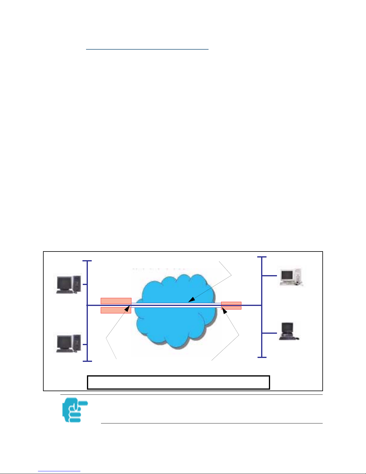
VPN IPSec Pass Through
This Cayman service supports your independent VPN client software in a
transparent manner. Cayman has implemented an Application Layer Gateway (ALG) to support multiple PCs running IP Security protocols.
This feature has three elements:
1. On power up or reset, the address mapping function (NAT) of the Gateway’s
WAN configuration is turned on by default.
2. When you use your third-party VPN application, the Gateway recognizes the
traffic from your client and your unit. It allows the packets to pass through the
NAT “protection layer” via the encrypted IPSec tunnel.
3. The encrypted IPSec tunnel is established “through” the Gateway.
A typical VPN IPSec Tunnel pass through is diagrammed below:
Cayman
Gateway
Typically, no special configuration is necessary to use the IPSec pass
through feature. This feature may need to be disabled for special VPN
clients that are designed to be supported through NAT.
In the diagram, VPN PC clients are shown behind the Cayman Gateway and the secure server is at Corporate Headquarters across the
WAN. You cannot have your secure server behind the Cayman Gateway.
When multiple PCs are starting IPSec sessions, they must be started
one at atime to allow the associations to be created and mapped.
27
Page 28
Section 3 General
SafeHarbour VPN IPSec Tunnel
SafeHarbour VPN IPSec Tunnel provides a single, encrypted tunnel to be
terminated on the Gateway, making a secure tunnel available for all LANconnected Users. This implementation offers the following:
• Eliminates the need for VPN client software on individual PC’s.
• Reduces the complexity of tunnel configuration.
• Simplifies the ongoing maintenance for secure remote access.
A VPN tunnel is a secure link between two networks interconnected over
an IP network providing a secure, cost-effective alternative to dedicated
leased lines.
SafeHarbour employs VPN standards, including:
• Internet Protocol Security (IPSec) suite, a series of protocols including
encryption, authentication, integrity, and replay protection.
• Internet Key Exchange (IKE), a management protocol of IPSec.
Adherence to VPN standards allows seamless interoperability between a
Cayman Gateway and another standards-based encryptor. SafeHarbour
supports:
“HQNetOne”
• Symmetric encryption protocols DES, 3DES, Blowfish, and CAST
• Hash algorithms MD5 and SHA1
• Diffie-Hellman groups 1, 2, and 5.
Terms are defined in the Glossary and How To sections.
Encrypted IPSec Tunnel
“RemoteNetTwo”
IP Network
Tunnel Terminates
at Standards-based Gateway
Tunnel Terminates
at Cayman Gateway
SafeHarbour VPN IPSec Tunnel Termination
An important feature of the SafeHarbour VPN IPSec Tunnel is secure
encryption of the configured circuit in both directions.
28
Page 29

Section 4 Access the User Interface
Web-based User Interface
Section 4
Access the User Interface
Using the embedded Web-based user interface for the Netopia Caymanseries Gateway you can configure, troubleshoot, and monitor the status of
your Gateway. For COS Version 6.3 the Web-based UI has been modified:
• To accomodate multiple new features of COS 6.3.
• To make using the entire facility easier.
Open the Web Connection
Once your Gateway is powered up, you can use any recent version of the
best-known web browsers that support javascript and Cascading Style
Sheets from any LAN-attached PC or workstation.
The procedure is:
Step 1 Enter the name or IP address of your Cayman Gateway in the Web browser's
window and click
For example, you would enter
using its default IP address. You can enter
period) or
network configuration from a DHCP server.
http://cayman-dsl.
Enter
.
http://192.168.1.254
http://cayman-2e.
if your computer has been configured to obtain its
if your Cayman Gateway is
(including the final
Step 2 If an administrator or user password has been assigned to the Cayman
Gateway, enter
password and click
The Cayman Gateway Home page opens.
If the Gateway is not configured, after logon you will see the Quickstart page.
Admin
OK
or
.
User
as the username and the appropriate
29
Page 30

Section 4 Home page
Home page
The Home page is the “dashboard” for your Cayman Gateway . The toolbar
at the top provides links to controlling, configuring, and monitoring pages.
Critical configuration and operational status is displayed in the center section. If you log on as Admin you see this page.
This example screen is from the Dual Ethernet Gateway.
The Home page differs slightly between DSL and Dual Ethernet Gateways.
Home page - User Mode, DSL Gateway
30
Page 31

Section 4 Home page
Home page - Information
The Home page’s center section contains a summary of the Gateway’s
configuration settings and operational status.
Summary Information
Field Status and/or Description
General Information
Hardware Model number and summary specification
Serial Number Unique serial number, located on label attached to bottom of unit
Software Ver-
sion
Product ID Refers to internal circuit board series; useful in determining which software
Optional (Keyed)
- BreakWater
Firewalll
WAN
Status Wide Area Network is either Up or Down
IP Address IP address assigned to the WAN port.
Default Gate-
way
DHCP Client Default setting lets a WAN host configure the IP address and other network
NAT On or Off. ON if using Network Address Translation to share the IP address
Netmask Defines the IP subnet for the WAN
DHCP Lease
Expires
Release and build number of running Cayman Operating System.
upgrade applies to your hardware type.
Indicates which BreakWater Basic Firewall protection level is enabled:
ClearSailing, SilentRunning, or LANdLocked
IP address of the host to which your Gateway sends network traffic when it
can’t find the destination host.
settings for the WAN interface of your Cayman Gateway.
across many LAN users.
Displays the amount of time remaining on current lease
WAN Users Displays the number of users allotted and the total number available for use.
LAN
IP Address Internal IP address of the Cayman Gateway.
Netmask Defines the IP subnet for the LAN
Default is 255.255.255.0 for a Class C device
DHCP Server On or Off. ON if using DHCP to get IP addresses for your LAN client machines.
DNS IP address of the Domain Name Server.
Leases in Use A “lease” is held by each LAN client that has obtained an IP address through
DHCP.
31
Page 32

Section 4 Toolbar
Toolbar
The toolbar is the dark blue bar at the top of the page containing the
major navigation buttons. These buttons are available from almost every
page, allowing you to move freely about the site. The example toolbar
shown below is displayed when you log on as Admin. If you log on as
User, some buttons will not be shown.
Home Configure Troubleshoot Security Install Restart Help
Quickstart System Status Passwords Install Keys
LAN Network
Tools
WAN Diagnostics IPSec
Advanced Security Log
Firewall Install Soft-
Navigating the Web Interface
Link
Response
Comment
Breadcrumb Trail
The breadcrumb trail is built in the light brown area beneath the toolbar.
As you navigate down a path within the site, the trail is built from left to
right. To return anywhere along the path from which you came, click on
one of the links.
ware
32
Page 33

Section 4 Restart
Restart
Button
Response
Restart
Comment
The Restart button on the toolbar allows you to restart the Gateway at
any time. You will be prompted to confirm the restart before any action is
taken. The Restart Confirmation message explains the consequences of
and reasons for restarting the Gateway
33
Page 34

Section 4 Restart
Link
Response
Comment
Alert Symbol
The Alert symbol appears in the upper right corner under one of two circumstances:
1. a database change; one in which a change is made to the Gateway’s
configuration. The Alert serves as a reminder that you must Save the
changes and Restart the Gateway before the change will take effect. You
can make many changes on various pages, and even leave the browser
for up to 8 minutes, but if the Gateway is restarted before the changes
are applied, they will be lost. When you click on the Alert symbol, the
Save Changes page appears. Here you can select various options to save
or discard these changes.
2. a security event is logged. If you have Security Monitoring keyed, you
receive Alerts whenever there is an event in the log that has not been
viewed. When you click the Alert symbol the Security Log is displayed
and the Alert clears.
If both types of Alert are triggered, you will need to take action to clear
the first type of Alert before you can see the second Alert.
34
Page 35

Section 4 Help
Help
Button
Response
Help
Comment
Context-sensitive Help is provided in Release 6.3. The page shown above
is displayed when you are on the Home page or other transitional pages.
To see a context help page example, go to
Help
click
.
Security -> Passwords
, then
35
Page 36

Section 4 Configure
Configure
Button
Comment
Quickstart
Configure
The Configuration options are presented in the order of likelihood you
will need to use them. Quickstart is typically accessed during the hardware installation and initial configuration phase. Often, these settings
should be changed only in accordance with information from your
Service Provider. LAN and WAN settings are available to fine-tune your
system. Advanced provides some special capabilities typically used for
gaming or small office environments, or where LAN-side servers are
involved.
This button will not be available if you log on as User.
How to Use the Quickstart Page
Quickstart is normally used immediately after the new hardware is
installed. When you are first configuring your Gateway, Quickstart
appears after you log on.
(Once you have configured your Gateway, logging on displays the Home
page. Thereafter, if you need to use Quickstart, choose it from the Configure menu.)
The Quickstart page you see depends on your type of Gateway and the
type of connection to your service provider. You may have one of the following types of connection to your service provider:
• DHCP (without PPP) - see “Setup Your Gateway using a DHCP Connec-
tion” on page 37
• PPP - see “Setup Your Gateway using a PPP Connection” on page 40
• Static IP Address - “Setup Your Gateway using a Static IP Address” on
page 41
36
Page 37

Section 4 Configure
Link
Response
Comment
Configure -> Quickstart
Setup Your Gateway using a DHCP Connection
This example screen is for a DHCP Quickstart configuration.
Your Service Provider will instruct you as to whether or not the Other
Quickstart Options need to be configured. If they are not needed, you
should be ready to access the Internet.
If required, click the
Options page.
Advanced
link to access the Other Quickstart
The Other Quickstart Options page allows you to change the System
Name or your Gateway’s Ethernet MAC address.
System Name is your Gateway’s factory identifier combined with its serial
number. By default, this identifier is automatically captured for this field.
37
Page 38

Section 4 Configure
Some broadband cable-oriented Service Providers use the System Name as
an important identification and support parameter. If your Gateway is part of
this type of network, do NOT alter the System Name unless specifically
instructed by your Service Provider
If you need to change either of these fields, use the following procedure.
Change Procedure
Step 1 Enter your selected System Name.
You can use the default System name or select your own. The System Name can
be 1-32 characters long.
Step 2 Select the
A new field is displayed.
Enter your 12-character Ethernet MAC override address as instructed by your
service provider, for example: 12 34 AB CD 19 64
Step 3 Click
This turns on the Alert (“!”) button in the top right corner of the page.
Step 4 Click the
Step 5 Click on the
Enable MAC Override
Submit
Alert
checkbox.
.
button to go to the page to save your changes.
Save and Restart
link.
38
Page 39

Section 4 Configure
You will be returned to the Home page. A warning is displayed on this page while
the Gateway restarts.
39
Page 40

Section 4 Configure
Setup Your Gateway using a PPP Connection
Response
Comment
This example screen is the for a PPP Quickstart configuration. Your
gateway authenticates with the Service Provider equipment using the ISP
Username and Password. These values are given to you by your Service
Provider.
Step 1 Enter your ISP Username and ISP Password.
Step 2 Click
Step 3 Click the
Step 4 Click on the
Submit
This turns on the Alert (“!”) button in the top right corner of the page.
.
Alert
button to go to the page to save your changes.
Save and Restart
link.
You will be returned to the Home page. A warning is displayed on this
page while the Gateway restarts.
40
Page 41
Section 4 Configure
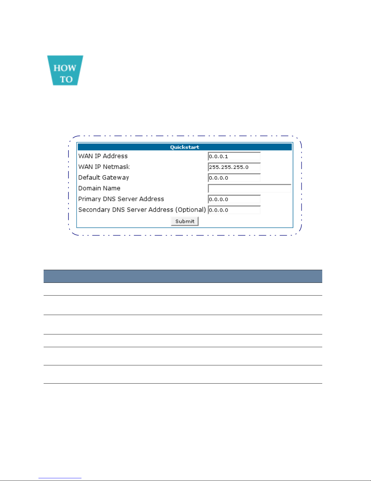
Setup Your Gateway using a Static IP Address
If your service provider supplies you with a static IP address, your Gate-
way’s Quickstart page will offer the fields required to enter the appropri-
ate information for this type of configuration.
Configuration Procedure
The Quickstart page designed for a static IP address offers the following fields for
you to supply the required information:
Step 1 Enter the values provided by your Internet Service Provider in the Quickstart
fields. Complete the following fields:
Field Description
WAN IP Address
WAN IP Netmask
The IP address assigned to your Cayman Gateway.
Defines the IP subnet mask for the WAN network connected to your
Gateway.
Default Gateway
IP address of the host to which the Cayman Gateway should send network traffic when it can't find the destination host.
Domain Name
Primary DNS
Server Address
Secondary DNS
Server Address
Step 2 Click the
Step 3 The
The domain name supplied by your service provider.
The IP address of the primary DNS name server for your network.
The IP address of the backup DNS name server for your network.
Submit
Alert
button appears. Click the
button to save the modified configuration.
Alert
button.
41
Page 42

Section 4 Configure
Step 4 When you see the Save Changes page, click the
Save and Restart
link to
restart your Cayman Gateway with its new configuration settings.
You will be returned to the Home page. A warning is displayed on this
page while the Gateway restarts.
Step 5 After your Cayman Gateway restarts, use your browser to verify that you
can access the Internet.
Your Cayman Gateway can now use the configured IP parameters
Do NOT confuse this procedure that establishes an IP address for the Gateway’s default IP traffic with configuring multiple static IP addresses used with
the IPMaps feature
42
Page 43
Section 4 Configure
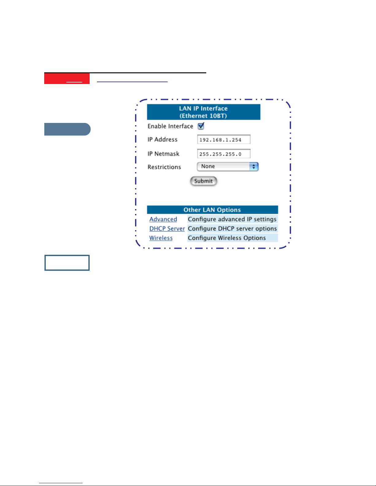
LAN
Link
Response
Configure -> LAN
Comment
* Interface Enable: Enables all LAN-connected computers to shared
resources and to connect to the WAN. The Interface should always be
enabled unless you are instructed to disable it by your Service Provider
during troubleshooting.
* IP Address: The LAN IP Address of the Gateway. The IP Address you
assign to your LAN interface must not be used by another device on your
LAN network.
* IP Netmask: Specifies the subnet mask for the TCP/IP network connected to the virtual circuit. The subnet mask specifies which bits of the
32-bit binary IP address represent network information. The default subnet mask for most networks is 255.255.255.0 (Class C subnet mask.)
* Restrictions: Specifies whether an administrator can open a Telnet
connection to the Gateway over the LAN interface in order to monitor
and configure the Gateway. On the LAN Interface, you can enable or disable administrator access. By default, administrative restrictions are
turned off, meaning an administrator can open a Telnet connection
through the LAN Interface.
43
Page 44
Section 4 Configure
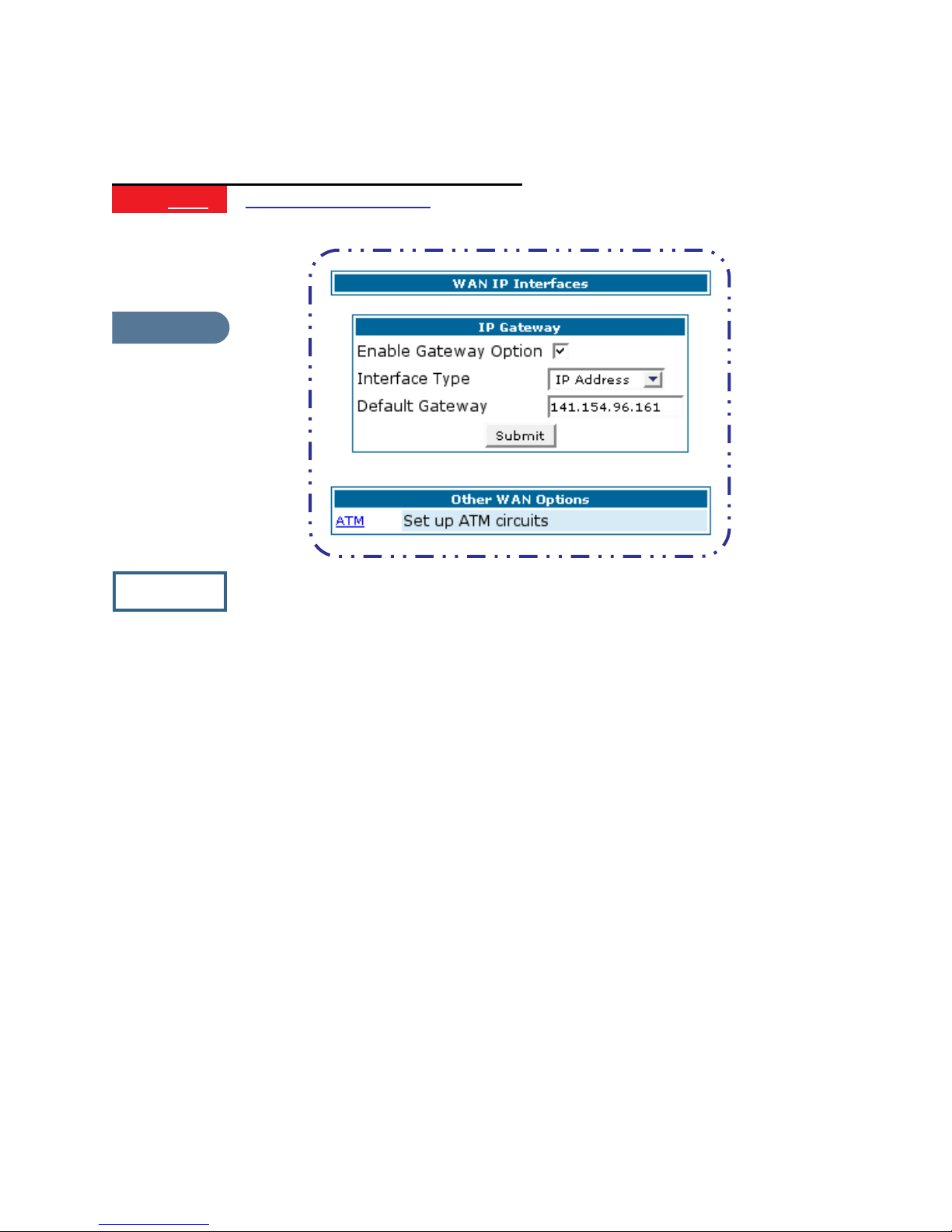
WAN
Link
Response
Comment
Configure -> WAN
WAN IP Interfaces
Your IP interfaces are listed. Click on an interface to configure it.
IP Gateway
Enable Gateway: You can configure the Gateway to send packets to a
default gateway if it does not know how to reach the destination host.
Interface Type: If you have PPPoE enabled, you can specify that packets
destined for unknown hosts will be sent to the gateway being
used by the remote PPP peer.. If you select ip-address, you
must enter the IP address of a host on a local or remote network to receive the traffic.
Default Gateway: The IP Address of the default gateway.
Other WAN Options
PPPoE: You can enable PPPoE and the number of PPPoE Sessions. The IP
Interface(s) should be reconfigured after changing this setting.
ATM: You can configure the A TM cir cuits and the number of Sessions. The IP
Interface(s) should be reconfigured after making changes
here.
44
Page 45

Section 4 Configure
Advanced
The following are links under Configure -> Advanced:
Link
Comment
Link
Response
Advanced
Selected Advanced options are discussed in the pages that follow . Many
are self-explanatory or are dictated by your service provider.
IP Static Routes
Description
A static route identifies a manually configured pathway to a remote net-
work. Unlike dynamic routes, which are acquired and confirmed peri-
odically from other routers, static routes do not time out. Consequently ,
static routes are useful when working with PPP, since an intermittent
PPP link may make maintenance of dynamic routes problematic.
You can configure as many as 16 static IP routes for the Gateway.
45
Page 46

Section 4 Configure
Link
Response
Description
IP Static ARP
Your Gateway maintains a dynamic Address Resolution Protocol (ARP)
table to map IP addresses to Ethernet (MAC) addresses. It populates this
ARP table dynamically, by retrieving IP address/MAC address pairs only
when it needs them. Optionally, you can define static ARP entries to
map IP addresses to their corresponding Ethernet MAC addresses.
Unlike dynamic ARP table entries, static ARP table entries do not time
out. The IP address cannot be 0.0.0.0. The Ethernet MAC address entry
is in nn-nn-nn-nn-nn-nn (hexadecimal) format.
Link
Response
Description
Pinholes
Pinholes allow you to transparently route selected types of network traf-
fic, such as FTP requests or HTTP (Web) connections, to a specific host
behind the Gateway . Creating a pinhole allows access traffic originating
from a remote connection (WAN) to be sent to the internal computer
(LAN) that is specified in the Pinhole page.
Contact your Network Administrator for LAN security questions.
Pinholes are common for applications like multiplayer online games.
Refer to software manufacturer application documentation for specific
traffic types and port numbers.
46
Page 47

Section 4 Configure
Configure Specific Pinholes
Planning for Your Pinholes
Determine if any of the service applications that you want to provide on
your LAN stations utilize TCP or UDP protocols. If an application does,
then you must configure an Internal Server to implement port forwarding.
This is accessed from the Advanced -> Internal Servers page.
Example: A LAN Requiring Three Pinholes
The procedure on the following pages describes how you set up your NATenabled Cayman Gateway to support three separate applications. This
requires passing three kinds of specific IP traffic through to your LAN.
Application 1: You have a Web server located on your LAN behind your
Cayman Gateway and would like users on the Internet to have access to it.
With NAT “On”, the only externally visible IP address on your network is
the Gateway’s WAN IP (supplied by your Service Provider). All traffic
intended for that LAN Web server must be directed to that IP address.
Application 2: You want one of your LAN stations to act as the “central
repository” for all email for all of the LAN users.
Application 3: One of your LAN stations is specially configured for game
applications. Again, you want this specific LAN station to be dedicated to
games.
A sample table to plan the desired pinholes is:
WAN Traffic Type Protocol Pinhole Name LAN Internal IP Address
Web TCP my-webserver 192.168.1.1
Email TCP my-mailserver 192.168.1.2
Games UDP my-games 192.168.1.3
For this example, Internet protocols TCP and UDP must be passed through
the NAT security feature and the Gateway’s embedded Web (HTTP) port
must be re-assigned by configuring new settings on the Internal Servers
page.
47
Page 48

Section 4 Configure
TIPS for making Pinhole Entries
1. If the port forwarding feature is required for Web services, ensure that the
embedded Web server’s port number is re-assigned PRIOR to any Pinhole data entry.
2. Enter data for one Pinhole at a time.
3. Use a unique name for each Pinhole.
If you choose a duplicate name, it will overwrite the previous information without warning.
A diagram of this LAN example is:
Internet
Gateway
WAN
Ethernet
Interface
210.219.41.20
NAT
Embedded
Web Server
210.219.41.20:8100
NAT Pinholes
LAN
Ethernet
Interface
my-webserver
192.168.1.1
my-mailserver
192.168.1.2
my-games
192.168.1.3
48
Page 49

Section 4 Configure
Pinhole Configuration Procedure
Use the following steps:
Step 1 From the
Servers
Since Port Forwarding is required for this example, the Cayman embedded Web
server is configured first.
link.
The two text boxes, Web (HTTP) Server Port and Telnet Sever Port, on this
page refer to the port numbers of the Cayman Gateway’s embedded admin-
istration ports.
To pass Web traffic through to your LAN station(s), select a Web (HTTP)
Port number that is greater than 1024. In this example, you choose 8100.
Step 2 Type
Step 3
8100
Configure
toolbar button ->
Advanced
in the Web (HTTP) Server Port text box.
link, select the
Internal
Step 4 Click the
Step 5 Click
Advanced
Submit
button.
. Select the
Pinholes
link to go to the Pinhole page.
49
Page 50

Section 4 Configure
Step 6 Click
Click
Add
. Type your specific data into the Pinhole Entries table of this page.
Submit
Step 7 Click on the
page. Click
Pinhole.
.
Pinholes
Add
link in the Breadcrumb Trail to go to the Pinholes entry
. Add the next Pinhole. Type the specific data for the second
Step 8 Click on the
page. Click the
third Pinhole.
Pinholes
Add
. Add the next Pinhole. Type the specific data for the
link in the Breadcrumb Trail to go to the Pinholes entry
50
Page 51

Section 4 Configure
Note the following parameters for the “my-games” Pinhole:
1. The Protocol ID is UDP.
2. The external port is specified as a range.
3. The Internal port is specified as the lower range entry.
Step 9 Click on the
page. Review your entries to be sure they are correct.
Step 10 Click the
Step 11 Select the
Alert
Save and Restart
and ensure that the parameters are properly saved.
REMEMBER: When you have re-assigned the port address for the
embedded Web server, you can still access this facility.
Use the Gateway’s WAN address plus the new port number.
In this example it would be
<WAN Gateway address>:<new port number> or, in this case,
210.219.41.20:8100
Pinholes
button.
link in the Breadcrumb Trail to go to the Pinholes entry
link to complete the entire Pinhole creation task
51
Page 52

Section 4 Configure
Link
Response
Comment
IPMaps
IPMaps supports one-to-one Network Address Translation (NAT) for IP
addresses assigned to servers, hosts, or specific computers on the LAN
side of the Cayman Gateway.
A single static or dynamic (DHCP) WAN IP address must be assigned to
support other devices on the LAN. These devices utilize Cayman’s default
NAT/PAT capabilities.
Configure the IPMaps Feature
FAQs for the IPMaps Feature
Before configuring an example of an IPMaps-enabled network, review
these frequently asked questions.
What are IPMaps and how are they used?
The IPMaps feature allows multiple static WAN IP addresses to be
assigned to the Cayman Gateway.
Static WAN IP addresses are used to support specific services, like a web
server, mail server, or DNS server . This is accomplished by mapping a separate static WAN IP address to a specific internal LAN IP address. All traffic
arriving at the Gateway intended for the static IP address is transferred to
the internal device. All outbound traffic from the internal device appears to
originate from the static IP address.
Locally hosted servers are supported by a public IP address while LAN users
behind the NAT-enabled IP address are protected.
IPMaps is compatible with the use of NAT, with either a statically assigned
IP address or DHCP/PPP served IP address for the NAT table.
52
Page 53

Section 4 Configure
What types of servers are supported by IPMaps?
IPMaps allows a Cayman Gateway to support servers behind the Gateway,
for example, web, mail, FTP, or DNS servers. VPN servers are not supported
at this time.
Can I use IPMaps with my PPPoE or PPPoA connection?
Yes. IPMaps can be assigned to the WAN interface provided they are on
the same subnet. Service providers will need to ensure proper routing to
all IP addresses assigned to your WAN interface.
Will IPMaps allow IP addresses from different subnets to be assigned to my
Gateway?
IPMap will support statically assigned WAN IP addresses from the same
subnet.
WAN IP addresses from different subnets are not supported.
53
Page 54

Section 4 Configure
IPMaps Block Diagram
The following diagram shows the IPMaps principle in conjunction with
existing Cayman NAT operations:
Cayman Gateway
Static IP Addresses
for IPMaps Applications
143.137.50.37
143.137.50.36
143.137.50.35
Static IP Addresses
or
DHCP/PPP Served IP Address
for Cayman’s default NAT/P A T
Capabilities
WAN Interface LAN Interface
IPMaps:
One-to-One
Multiple Address Mapping
NA T/P A T Tab le
143.137.50.37
143.137.50.36
143.137.50.35
LAN stations with WAN IP traffic
forwarded by Cayman’s IPMaps
LAN stations with WAN IP traffic
forwarded by Cayman’s NAT function.
...
192.168.1.1
192.168.1.2
192.168.1.3
...
192.168.1.n
192.168.1.1
192.168.1.2
192.168.1.3
.
.
.
192.168.1.n
54
Page 55

Section 4 Configure
Link
Response
Description
Protocol Lifetimes
Each NAT Protocol map entry will time-out if there is no traffic of that
protocol for the specified number of minutes. For example, UDP entries
time-out if there is no UDP traffic after 6 (default) minutes.
Link
Response
Description
Default Server
This feature allows you to:
* Direct your Gateway to forward all externally initiated IP traffic (TCP
and UDP protocols only) to a default host on the LAN.
* Enable it for certain situations:
– Where you cannot anticipate what port number or packet
protocol an in-bound application might use. For example, some
network games select arbitrary port numbers when a connection
is opened.
– When you want all unsolicited traffic to go to a specific LAN host.
55
Page 56

Section 4 Configure
Configure a Default Server
This feature allows you to direct unsolicited or non-specific traffic to a designated LAN station. With NAT “On” in the Gateway, these packets normally would be discarded.
For instance, this could be application traffic where you don’t know (in
advance) the port or protocol that will be utilized. Some game applications
fit this profile.
Use the following steps to setup a NAT default server to receive this information:
Step 1 Select the
Step 2 Check the
appears.
Step 3 Determine the IP address of the LAN computer you have chosen to receive
the unexpected or unknown traffic. Enter this address in the NAT Server IP
Address field.
Step 4 Click the
Step 5 Click the
Step 6 Click the
Configure
toolbar button, then
Enable Default Server
Submit
Alert
Save and Restart
button.
button.
link to confirm.
Advanced
checkbox. The NAT Server IP Address field
, then the
Default Server
link.
NAT Default Server capability is not available over SafeHarbour IPsec.
56
Page 57

Section 4 Configure
Typical Network Diagram
A typical network utilizing the NAT Default Server looks like this:
Internet
Gateway
LAN STN #3
192.168.1.3
WAN
Ethernet
Interface
210.219.41.20
LAN
Ethernet
Interface
NAT
LAN STN #2
192.168.1.2
NAT protected
Embedded
NAT Pinhole
Web Server
210.219.41.20
(Port 80 default)
NAT Default Server
192.168.1.1
NAT Combination Application
Cayman’s NAT security feature allows you to configure a sophisticated LAN
layout that uses both the Pinhole and Default Server capabilities.
With this topology, you configure the embedded administration ports as a
first task, followed by the Pinholes and, finally, the NAT Default Server.
When using both NAT pinholes and NAT Default Server the Gateway works
with the following rules (in sequence) to forward traffic from the Internet
to the LAN:
1. If the packet is a response to an existing connection created by outbound traf-
fic from a LAN PC, forward to that station.
2. If not, check for a match with a pinhole configuration and, if one is found, for-
ward the packet according to the pinhole rule.
3. If there’s no pinhole, the packet is forwarded to the Default Server.
57
Page 58

Section 4 Configure
Link
Response
Description
DNS
Your Service Provider may maintain a Domain Name server. If you have
the information for the DNS servers, enter it on the DNS page. If your
Gateway is configured to use DHCP to obtain its WAN IP address, the
DNS information is automatically obtained from that same DHCP
Server.
58
Page 59
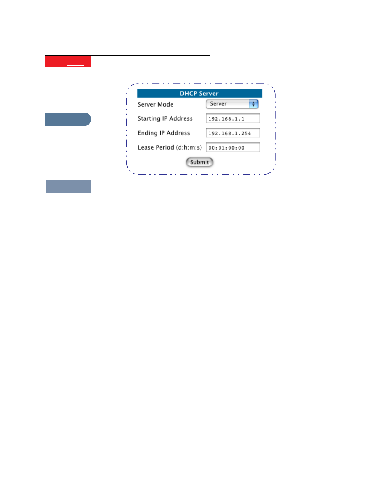
Section 4 Configure
Link
Response
Description
DHCP Server
Your Gateway can provide network configuration information to com-
puters on your LAN, using the Dynamic Host Configuration Protocol
(DHCP).
If you already have a DHCP server on your LAN, you should turn this
service off.
If you want the Gateway to provide this service, click the
Server Mode
pulldown menu, then configure the range of IP addresses that you
would like the Gateway to hand out to your computers.
You can also specify the length of time the computers can use the con-
figuration information; DHCP calls this period the lease time.
Your Service Provider may, for certain services, want to provide configu-
ration from its DHCP servers to the computers on your LANs. In this
case, the Gateway will relay the DHCP requests from your computers to
a DHCP server in the Service Provider's network.
Click the relay-agent and enter the IP address of the Service Provider's
DHCP server in the Server Address field. This address is furnished by the
Service Provider.
59
Page 60
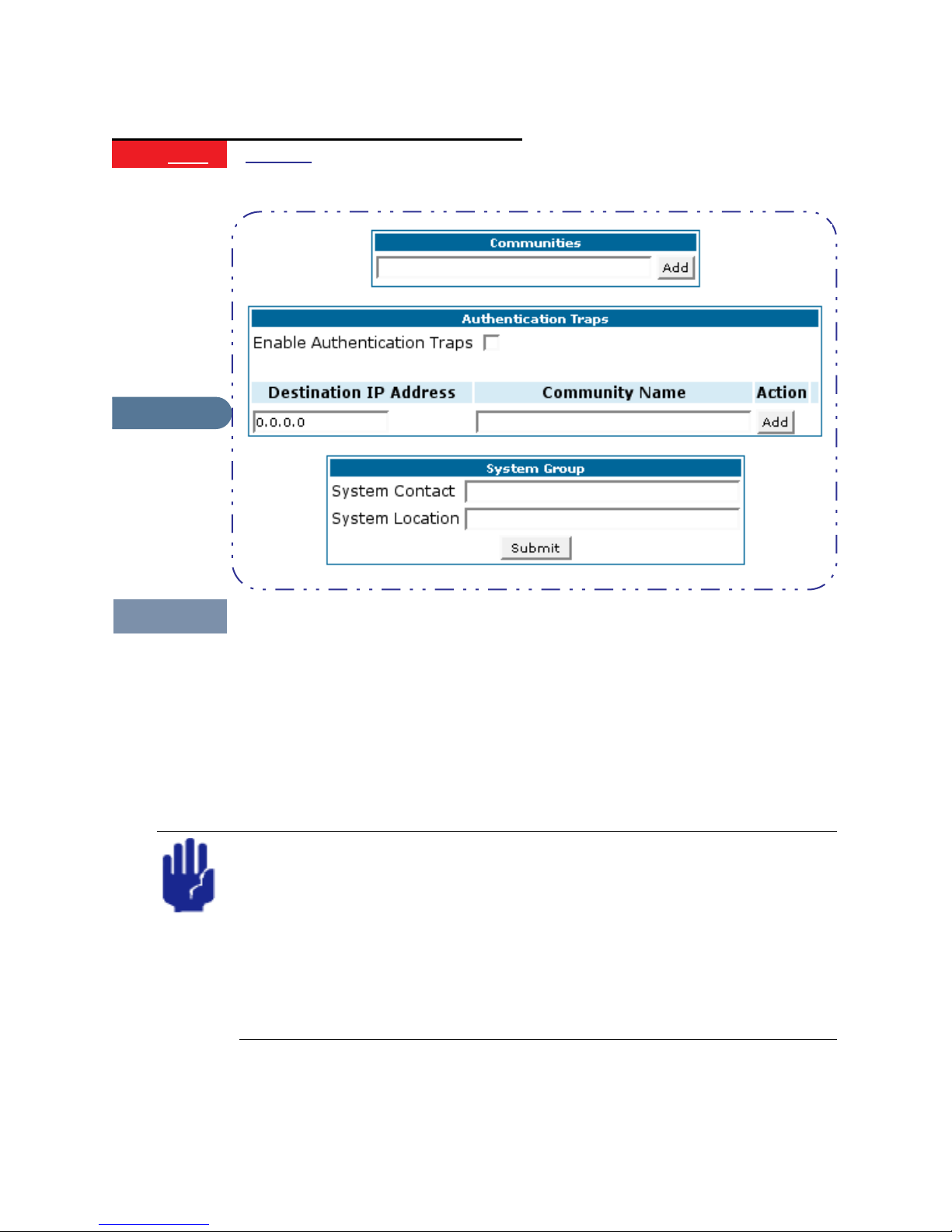
Section 4 Configure
Link
Response
SNMP
Description
The Simple Network Management Protocol (SNMP) lets a network
administrator monitor problems on a network by retrieving settings
on remote network devices. The network administrator typically runs
an SNMP management station program on a local host to obtain
information from an SNMP agent. In this case, the Cayman Gateway
is an SNMP agent.
You enter SNMP configuration information on this page.
Your network administrator furnishes the SNMP parameters.
SNMP presents you with a security issue. The community facility of
SNMP behaves somewhat like a password. The community “public”
is a well-known community name. It could be used to examine the
configuration of your Gateway by your service provider or an uninvited reviewer. While Cayman's SNMP implementation does not
allow changes to the configuration, the information can be read
from the Gateway.
If you are strongly concerned about security, you may delete the
“public” community.
60
Page 61

Section 4 Configure
Link
Response
Description
Ethernet Bridge
Bridges let you join two local area networks, so that they appear to be
part of the same physical network. As a bridge for protocols other than
TCP/IP, your Gateway keeps track of as many as 255 MAC (Media
Access Control) addresses, each of which uniquely identifies an individ-
ual host on a network. Your Gateway uses this bridging table to identify
which hosts are accessible through which of its network interfaces. The
bridging table contains the MAC address of each packet it sees, along
with the interface over which it received the packet. Over time, the
Gateway learns which hosts are available through its WAN port, its LAN
port, and/or its wireless interface.
61
Page 62

Section 4 Configure
Link
Response
Description
System
The System Name defaults to your Gateway's factory identifier com-
bined with its serial number. Some cable-oriented Service Providers use
the System Name as an important identification and support parame-
ter. If your Gateway is part of this type of network, do NOT alter the
System Name unless specifically instructed by your Service Provider.
The System Name can be 1-63 characters long; it can include embed-
ded spaces and special characters.
The Log Message Level alters the severity at which messages are col-
lected in the Gateway's system log. Do not alter this field unless
instructed by your Support representative.
62
Page 63

Section 4 Configure
Link
Response
Description
Internal Servers
Your Gateway ships with an embedded Web server and support for a
Telnet session, to allow ease of use for configuration and maintenance.
The default ports of 80 for HTTP and 23 for Telnet may be reassigned.
This is necessary if a pinhole is created to support applications using
port 80 or 23. See “Pinholes” on page 46 for more information on Pin-
hole configuration.
Web (HTTP) Server Port: To reassign the port number used to access
the Cayman embedded Web server , change this value to a value greater
than 1024. When you next access the embedded Cayman Web server,
append the IP address with <port number>, (e.g. Point your browser to
http://210.219.41.20:8080)
Telnet Server Port: To reassign the port number used to access your
Cayman embedded Telnet server, change this value to a value greater
than 1024. When you next access the Cayman embedded T elnet server ,
append the IP address with <port number>, (e.g. telnet
210.219.41.20:2323)
63
Page 64

Section 4 Configure
Link
Response
Description
Link
Ethernet MAC Address
Override
You can override your Gateway’s Ethernet MAC address with any neces-
sary setting. Some ISPs require your account to be identified by the
MAC address, among other things. For information on setting this
parameter , see “How to Use the Quickstart Page” on page 36.
Traffic Shaping
Response
Description
Traffic shaping controls how much traffic can flow through an Ethernet
interface by limiting the size of the Ethernet pipe. This function is most
suitable for Internet Service Providers.
Enable Traffic Shaping on Port: Each Ethernet port providing traffic
shaping capability is listed. Enable the port to set the traffic shaping
rate.
Rate: This value, in bits per second, indicates the approximate speed at
which traffic will flow.
64
Page 65

Section 4 Configure
Link
Response
Description
Comment
Clear Options
To restore the factory configuration of the Gateway, choose Clear
Options. You may want to upload your configuration to a file before
performing this function.
Clear Options does not clear feature keys or affect the software image
or BootPROM.
You must restart the Gateway for Clear Options to take effect.
65
Page 66

Section 4 Configure
Security
Button
Response
Description
Security
The Security features are available by clicking on the Security toolbar
button. Some items of this category do not appear when you log on as
User.
Link
Description
Passwords
Access to your Gateway is controlled through two user accounts,
Admin and User. When you first power up your Gateway, you create a
password for the Admin account. The User account does not exist by
default. As the Admin, a password for the User account can be entered
or existing passwords changed.
66
Page 67

Section 4 Configure
Create and Change Passwords
You can establish different levels of access security to protect your Cay-
man Gateway settings from unauthorized display or modification.
• Admin level privileges let you display and modify all settings in the
Cayman Gateway (Read/Write mode). The Admin level password is created when you first access your Gateway.
• User level privileges let you display (but not change) settings of the
Cayman Gateway. (Read Only mode)
To prevent anyone from observing the password you enter, characters in
the old and new password fields are not displayed as you type them.
To display the Passwords window, click the
Home page.
Security
toolbar button on the
Use the following procedure to change existing passwords or add the User
password for your Cayman Gateway:
Step 1 Select the password type from the
Choose from Admin or User.
Step 2 If you assigned a password to the Cayman Gateway previously, enter your
current password in the
Step 3 Enter your new password in the
Cayman’s rules for a Password are:
Password Level
Old Password
New Password
pull-down list.
field.
field.
67
Page 68

Section 4 Configure
• It can have up to eight alphanumeric characters.
• It is case-sensitive.
Step 4 Enter your new password again in the
You confirm the new password to verify that you entered it correctly the first time.
Step 5 When you are finished, click the
Submit
configuration in the Cayman unit’s memory.
Password changes are automatically saved, and take effect immediately.
Confirm Password
field.
button to store your modified
68
Page 69

Section 4 Configure
Link
Firewall
Use a Cayman Firewall
BreakWater Basic Firewall
BreakWater delivers an easily selectable set of pre-configured firewall protection levels. For simple implementation these settings (comprised of
three levels) are readily available through Cayman’s embedded web
server interface.
BreakWater Basic Firewall’s three settings are:
ClearSailing
ClearSailing, BreakWater's default setting, supports both inbound and outbound traffic. It is the only basic firewall setting that fully interoperates
with all other Cayman software features.
SilentRunning
Using this level of firewall protection allows transmission of outbound traffic on pre-configured TCP/UDP ports. It disables any attempt for inbound
traffic to identify the Gateway. This is the Internet equivalent of having an
unlisted number.
LANdLocked
The third option available turns off all inbound and outbound traffic, isolating the LAN and disabling all WAN traffic.
BreakWater Basic Firewall operates independent of the NAT
functionality on the Gateway.
Configuring for a BreakWater Setting
Use these steps to establish a firewall setting:
Step 1 Ensue that you have enabled the BreakWater basic firewall with the
appropriate feature key.
See “Use Cayman Software Feature Keys” on page 93 for reference.
Step 2 Click the
Step 3 Click
Security
Firewall
toolbar button.
.
69
Page 70

Section 4 Configure
Step 4 Click on the radio button to select the protection level you want. Click
Submit
.
Changing the BreakWater setting does not require a restart to take effect. This
makes it easy to change the setting "on the fly,” as your needs change.
TIPS for making your BreakWater Basic Firewall Selection
Application Select this Level Other Considerations
Typical Internet usage
(browsing, e-mail)
Multi-player online gaming ClearSailing Set Pinholes; once defined, pinholes will
Going on vacation LANdLocked Protects your connection while your away.
Finished online use for the
day
Chatting online or using
instant messaging
SilentRunning
be active whenever ClearSailing is set.
Restore SilentRunning when finished.
LANdLocked This protects you instead of disconnecting
your Gateway connection.
ClearSailing Set Pinholes; once defined, pinholes will
be active whenever ClearSailing is set.
Restore SilentRunning when finished.
70
Page 71

Section 4 Configure
Basic Firewall Background
As a device on the Internet, a Cayman Gateway requires an IP address in
order to send or receive traffic.
The IP traffic sent or received have an associated application port which is
dependent on the nature of the connection request. In the IP protocol
standard the following session types are common applications:
ICMP • HTTP • FTP
•
• SNMP • telnet • DHCP
By receiving a response to a scan from a port or series of ports (which is the
expected behavior according to the IP standard), hackers can identify an
existing device and gain a potential opening for access to an internet-connected device.
To protect LAN users and their network from these types of attacks, BreakWater offers three levels of increasing protection.
The following tables indicate the state of ports associated with ses-
sion types, both on the WAN side and the LAN side of the Gateway.
This table shows how inbound traffic is treated. Inbound means the traffic is
coming from the WAN into the WAN side of the Gateway.
Gateway: WAN Side
BreakWater Setting >> ClearSailing SilentRunning LANdLocked
Port Session Type --------------Port State-----------------------
20 ftp data Enabled Disabled Disabled
21 ftp control Enabled Disabled Disabled
23 telnet external Enabled Disabled Disabled
23 telnet Cayman server Enabled Disabled Disabled
80 http external Enabled Disabled Disabled
80 http Cayman server Enabled Disabled Disabled
67 DHCP client Enabled Enabled Disabled
68 DHCP server Not Applicable Not Applicable Not Applicable
161 snmp Enabled Disabled Disabled
ping (ICMP) Enabled Disabled Disabled
71
Page 72

Section 4 Configure
This table shows how outbound traffic is treated. Outbound means the traffic is coming from the LAN-side computers into the LAN side of the Gateway.
Gateway: LAN Side
BreakWater Setting >> ClearSailing SilentRunning LANdLocked
Port Session Type --------------Port State-----------------------
20 ftp data Enabled Enabled Disabled
21 ftp control Enabled Enabled Disabled
23 telnet external Enabled Enabled Disabled
23 telnet Cayman server Enabled Enabled Enabled
80 http external Enabled Enabled Disabled
80 http Cayman server Enabled Enabled Enabled
67 DHCP client Not Applicable Not Applicable Not Applicable
68 DHCP server Enabled Enabled Enabled
161 snmp Enabled Enabled Enabled
ping (ICMP) Enabled Enabled WAN - Disabled
LAN Local Address Only
The Gateway’s WAN DHCP client port in SilentRunning mode is enabled. This
feature allows end users to continue using DHCP-served IP addresses from their
Service Providers, while having no identifiable presence on the Internet.
72
Page 73

Section 4 Configure
Link
Response
IPSec
Description
Your Gateway supports two mechanisms for IPSec tunnels:
1. IPSec PassThrough supports Virtual Private Network (VPN) clients
running on LAN-connected computers. Normally , this feature is enabled.
However, you can disable it if your LAN-side VPN client includes its own
NAT interoperability option.
2. SafeHarbour VPN IPSec is a keyed feature that enables Gateway-terminated VPN support.
Configure a SafeHarbour VPN
VPN IPSec Tunnel at the Gateway
SafeHarbour VPN IPSec Tunnel provides a single, encrypted tunnel to be
terminated on the Gateway, making a secure tunnel available for all
LAN- connected Users. This implementation offers the following:
• Eliminates the need for VPN client software on individual PC’s.
• Reduces the complexity of tunnel configuration.
• Simplifies the ongoing maintenance for secure remote access.
73
Page 74

Section 4 Configure
A typical SafeHarbour configuration is shown below:
Use these Best Practices in establishing your SafeHarbour tunnel.
1. Ensure that the configuration information is complete and accurate
2. Use the Worksheet provided on page 76.
Parameter Description and Setup
The following table describes SafeHarbour’s parameters that are used for
an IPSec VPN tunnel configuration:
Auth Protocol Authentication Protocol for IP packet header. The three parameter values are
None, Encapsulating Security Payload (ESP) and Authentication Header (AH)
DH Group Diffie-Hellman is a public key algorithm used between two systems to determine
and deliver secret keys used for encryption. Groups 1, 2 and 5 are supported.
Enable This toggle button is used to enable/disable the configured tunnel.
Encrypt Protocol Encryption protocol for the tunnel session.
Parameter values supported include NONE or ESP.
Hard MBytes Setting the Hard MBytes parameter forces the renegotiation of the IPSec Security
Associations (SAs) at the configured Hard MByte value.
The value can be configured between 1 and 1,000,000 MB and refers to data traf-
fic passed.
Hard Seconds Setting the Hard Seconds parameter forces the renegotiation of the IPSec Security
Associations (SAs) at the configured Hard Seconds value. The value can be config-
ured between 60 and 1,000,000 seconds
Key Management The Key Management algorithm manages the exchange of security keys in the
IPSec protocol architecture. SafeHarbour supports the standard Internet Key
Exchange (IKE)
Peer External IP Address The Peer External IP Address is the public, or routable IP address of the remote
gateway or VPN server you are establishing the tunnel with.
Peer Internal IP NetworkThe Peer Internal IP Network is the private, or Local Area Network (LAN) address
of the remote gateway or VPN Server you are communicating with.
74
Page 75

Section 4 Configure
Peer Internal IP NetmaskThe Peer Internal IP Netmask is the subnet mask of the Peer Internal IP Network.
PFS DH Group Perfect Forward Secrecy (PFS) is used during SA renegotiation. When PFS is
selected, a Diffie-Hellman key exchange is required. SafeHarbour supports PFS DH
Groups 1, 2 and 5.
Pre-Shared Key The Pre-Shared Key is a parameter used for authenticating each side. The value
can be an ASCII or Hex and a maximum of 64 characters. ASCII is case-sensitive.
Pre-Shared Key Type The Pre-Shared Key Type classifies the Pre-Shared Key. SafeHarbour supports
ASCII or HEX types
Name The Name parameter refers to the name of the configured tunnel. This is mainly
used as an identifier for the administrator. The Name parameter is an ASCII value
and is limited to 31characters. The tunnel name is the only IPSec parameter that
does not need to match the peer gateway.
Negotiation Method This parameter refers to the method used during the Phase I key exchange, or IKE
process. SafeHarbour supports Main or Aggressive Mode. Main mode requires 3
two-way message exchanges while Aggressive mode only requires 3 total mes-
sage exchanges.
SA Encrypt Type SA Encryption Type refers to the symmetric encryption type. This encryption algo-
rithm will be used to encrypt each data packet. SA Encryption Type values sup-
ported include DES, 3DES, CAST and Blowfish.
SA Hash Type SA Hash Type refers to the Authentication Hash algorithm used during SA negoti-
ation. Values supported include MD5 and SHA1. N/A will display if NONE is cho-
sen for Auth Protocol.
Soft MBytes Setting the Soft MBytes parameter forces the renegotiation of the IPSec Security
Associations (SAs) at the configured Soft MByte value. The value can be config-
ured between 1 and 1,000,000 MB and refers to data traffic passed. If this value is
not achieved, the Hard MBytes parameter is enforced.
Soft Seconds Setting the Soft Seconds parameter forces the renegotiation of the IPSec Security
Associations (SAs) at the configured Soft Seconds value. The value can be config-
ured between 60 and 1,000,000 seconds.
75
Page 76

Section 4 Configure
IPSec Tunnel Parameter Setup Worksheet
Parameter Cayman Peer Gateway
Name
Peer External IP Address
Peer Internal IP Network
Peer Internal IP Netmask
Enable
Encrypt Protocol None
ESP
Auth Protocol None
ESP
AH
Key Management IKE
Pre-Shared Key Type HEX
ASCII
Pre-Shared Key
Negotiation Method Main
Aggressive
DH Group 1
2
5
SA Encrypt Type DES
3DES
CAST
Blowfish
SA Hash Type N/A
MD5
SHA1
PFS DH Group Off
1
2
Soft MBytes 1 - 1000000
Soft Seconds 60 - 1000000
Hard MBytes 1 - 1000000
Hard Seconds 60 - 1000000
5
76
Page 77

Section 4 Configure
SafeHarbour Tunnel Setup
Use the following tasks to configure an IPSec VPN tunnel on your Cayman
Gateway.
Task 1: Ensure that you have SafeHarbour VPN enabled.
SafeHarbour is a keyed feature. See page 93 for information concerning
installing Cayman Software Feature Keys.
Task2: Complete Parameter Setup Worksheet
IPSec tunnel configuration requires precise parameter set between VPN
devices. The Setup Worksheet facilitates setup and assures that the associated variables are identical.
Task 3: Enable IPSec
IPSec must be enabled on your Gateway to allow further VPN configuration. Perform the following steps to enable IPSec:
Step 1 Browse to Gateway.
Step 2 Click the
Step 3 Click the
Step 4 Check the
Checking this box will automatically display the SafeHarbour IPSec Tunnel
Entry parameters.
Security
IPSec
Enable SafeHarbour IPSec
toolbar button.
link.
checkbox.
77
Page 78

Section 4 Configure
Leave the
administrator instructs otherwise.
Enable NAT over Tunnel
Task 4: Make the IPSec Tunnel Entries
Enter the initial group of tunnel parameters. Refer to your Setup Worksheet and the Glossary of VPN Terms as required. Perform the following
steps:
Step 1 Enter tunnel
This is the only parameter that does not have to be identical to the peer/
remote VPN device
Step 2 Enter the
Step 3 Select
Step 4 Select
Step 5 Select
Encryption Protocol
Authentication Protocol
Key Management
Name
.
Peer External IP Address
from the pulldown menu.
from the pulldown menu.
from the pulldown menu.
choice as
.
Off
unless your network
78
Page 79

Section 4 Configure
Step 6 Ensure that the toggle checkbox
On.
Step 7 Click
Add
.
The Tunnel Details page appears.
Enable
, which is On by default, remains
Task 5: Make the Tunnel Details entries
Use the following steps:
Step 1 Enter or select the required settings.
Step 2 Click
Step 3 Click the
Step 4 Click
Update
Save and Restart
Your SafeHarbour IPSec VPN tunnel is fully configured.
Tunnel sessions can only be initiated from the LAN client side.
. The
Alert
Alert
button.
button appears.
.
79
Page 80

Section 4 Configure
Link
Response
Description
Step 1 Click the
Step 2 Click the
Security Log
Security Monitoring detects security-related events, including common
types of malicious attacks, and writes them to the security log file.
Using the Security Monitoring Log
You can view the Security Log at any time. Use the following steps:
Security toolbar button.
Security Log
link.
Step 3 Click the
An example of the Security Log is shown on the next page.
Step 4 When a new security event is detected, you will see the
The Security Alert remains until you view the information. Clicking the Alert
button will take you directly to a page showing the log.
Show
link from the Security Log tool bar.
Alert
button.
80
Page 81

Section 4 Configure
81
Page 82

Section 4 Configure
The capacity of the security log is 100 security alert messages. When the log
reaches capacity, subsequent messages are not captured, but they are noted in
the log entry count.
Remember that the “time stamp” is Universal Coordinated Time (UTC) which
is the equivalent of Greenwich Mean Time.
For your convenience, the table below lists the time offsets for various North
American time zones.
See Timestamp Background information on the next page for more details.
Table of Time Offsets (in hours) from GMT
Zone ->
Standard
Time -10 -9 -8 -7 -6 -5 -4 0
Daylight
Savings
Time
Hawaii Alaska P acific Mountain Central Eastern Atlantic UTC/GMT
N/A -8 -7 -6 -5 -4 -3 0
Take the recorded UTC/GMT value and subtract the offset value to get the
time that an event occurred in your system.
Reset
To reset this log, select
from the Security Monitor tool bar.
The following message is displayed.
When the Security Log contains no entries, this is the response
Timestamp Background
During bootup, to provide better log information and to support improved
troubleshooting, a Cayman Gateway acquires the National Institute of
Standards and Technology (NIST) Universal Coordinated Time (UTC) reference signal.
Once per hour, the Gateway attempts to re-acquire the NIST reference, for
re-synchronization or initial acquisition of the UTC information. Once
acquired, all subsequent log entries display this date and time information.
UTC provides the equivalent of Greenwich Mean Time (GMT) information.
If the WAN connection is not enabled, the internal clocking function of the
Gateway provides log timestamps based on “uptime” of the unit.
82
Page 83

Section 4 Configure
Install
Button
Response
Description
Install
From the Install toolbar button you can:
• Install new Operating System Software
• Install new Feature Keys
83
Page 84

Section 4 Configure
Install Software
Link
Response
Install Software
Comment
This page allows you to install an updated release of the Cayman
Operating System (COS).
Updating Your Gateway to COS Version 6.3
Cayman Operating System Release 6.3 represents significantly expanded
functionality for your Cayman Gateway. To deliver these important features, the COS 6.3 image is larger than earlier versions and the updating
process is different from earlier procedures. It requires careful attention to
the instruction sequence.
Using the Web Page
You install a new operating system image in your unit from the Cayman
embedded Web server’s Home page. For this process, the computer you
are using to connect to the Cayman Gateway must be on the same local
area network as the Cayman Gateway.
84
Page 85

Section 4 Configure
Required Tasks
Task # Description Page #
Warnings:
COS 6.3 is NOT SUPPORTED on the following models:
2E with PID of 06xx
2E or 2E-H with internal memory of 2MBytes or less
1 Locate and confirm the required files.
2 Install and verify the Updater application code.
3 Install and verify the COS 6.3 image.
86
87
89
Depending on your particular subscriber agreement, you may need to install
other feature key files.
COS 6.3 provides substantial new flexibility and functionality for your Cayman
Gateway. However, once you have upgraded to this version, you cannot revert
back to a previous release.
85
Page 86

Section 4 Configure
Task 1 Required Files
Upgrading to COS 6.3 requires THREE files:
1. Documentation -
2. Updater file
3. Cayman Operating System image
Software Upgrade Instructions
PDF file
Background
When you downloaded your operating system upgrade from the Cayman
website you downloaded a ZIP file containing these files:
Software Upgrade Instructions
•
PDF file (the document you are reading
now)
• Updater file for your particular Gateway
• Cayman Operating System image for your particular Gateway
Confirm Updater and COS Image Files
The Updater and COS Image files are specific to the model and the product identification (PID) number.
Step 1 Confirm that you have received the appropriate Updater and COS Image
files using this table:
Model PID Updater File
COS 6.3.0R0
Image
3220-H 07xx u8a110R0.COS c8a630R0.COS
3220-H 08xx u8j110R0.COS c8j630R0.COS
3220-H-W11 08xx u8w110R0.COS c8w630R0.COS
3220-H-WRF 08xx u8w110R0.COS c8w630R0.COS
2E {see Warnings} 07xx u8e110R0.COS c8e630R0.COS
2E-H {see Warnings} 07xx u8e110R0.COS c8e630R0.COS
2E-H-W11 09xx u8ew110R0.COS c8ew630R0.COS
2E-H-WRF 09xx u8ew110R0.COS c8ew630R0.COS
Step 2 Copy the confirmed Updater file to a convenient location on a computer on
your local area network. Be sure that you note the location.
Step 3 Copy the confirmed COS 6.3 file to the same location.
86
Page 87

Section 4 Configure
Contact Information
Contact Cayman Technical Support for questions concerning the upgrade
process.
Contact Cayman Sales for specific advanced features.
Use this contact information:
Web Access
Technical Support
Main Telephone
http://www.netopia.com/support
510-814-5000 ext 1
510-814-5100
Task 2 Updater File
Install Updater Application Code
If you are currently running a Cayman Operating System version COS 5.90 or
higher, skip this Task and continue to page 89 for Task 3.
Use these steps to install the Updater software in your Gateway from the
Home page:
Step 1 Open a web connection to your Gateway from a LAN computer.
From a web browser access the URL http://cayman-2E. or http://caymandsl. or http://192.168.1.254.
This Home page is from a Cayman 3220-H Gateway (DSL WAN access).
The Home page for a Cayman 2E-H Gateway (Ethernet WAN access) is similar.
Step 2 If necessary, save the LAN configuration settings on your Cayman Gateway.
If you have not previously saved your configuration (that is, if you are running the
factory default configuration your Cayman Gateway came with), click the
87
Page 88

Section 4 Configure
Ethernet
window appears, click
button on the Cayman Gateway Home page. When the Ethernet
Save
.
If you have previously saved your Cayman Gateway configuration, you can skip
this step.
Step 3 Click the
Install Software
button on the Cayman Gateway Home page.
The Install New Cayman Software window opens.
This page is from a Cayman 3220-H Gateway (DSL WAN access).
The page for a Cayman 2E-H Gateway (Ethernet WAN access) is similar.
Step 4 Enter the Updater filename into the text window with one of these
techniques:
The Updater file name starts with the letter “u“ (for “Updater”).
a. Click the
Browse
button, select the file you want, and click
Open
.
-orb. Enter the name and path of the update file you want to install in the text field.
Step 5 Click the
Install
button.
The Cayman Gateway copies the Updater file from your computer and installs it
into its memory storage. You see a series of dots appear on your screen as the
image is copied and installed. You have the following visual guide from your unit:
3220-H
2E-H
DSL and Status LED indicators will blink.
WAN LED indicator will blink.
When the image has been installed, the message “successful install of
file” appears at the bottom of the screen.
Step 6 When the “Please Click Restart” message appears, click the
button and confirm
Restart
.
Restart
88
Page 89

Section 4 Configure
Your Cayman Gateway restarts with its new image. During this step you have the
following visual guide from your unit:
3220-H
2E-H
DSL and Status LED indicators will blink for 30 seconds or more.
WAN LED indicator will blink for 30 seconds or more.
Verify Updater Application Code
To verify that the Updater image has loaded successfully , use the following
steps:
Step 7 Open a web connection to your Cayman Gateway from the computer on
your LAN; return to the Home page and select the
Step 8 Under the General toolbar, select the
Updater version 1.1
2002
Overview
2002
link.
Monitor
Verify
button.
This page is from a Cayman 3220-H Gateway (DSL WAN access).
The page for a Cayman 2E-H Gateway (Ethernet WAN access) is similar.
Step 9 Verify that the Cayman Gateway is running Updater version 1.1.
If the Updater is not running, the screen will show your COS version instead. If
your COS version is earlier than 5.9, return to Task 1 and retry the installation.
Task 3 COS 6.3 Image File
Install the COS 6.3 Image
The COS installation process is similar to the Updater installation.
To install the COS 6.3 software in your Cayman Gateway from the
use the following steps:
Page
Step 1 Open a web connection to your Cayman Gateway from the computer on
your LAN.
Step 2 Click the
The Install New Cayman Software window opens.
Install Software
button on the Cayman Gateway
Home
Home
page.
89
Page 90

Section 4 Configure
Step 3 Enter the filename into the text box by using one of these techniques:
The COS file name starts with the letter “c” (for “COS”).
a. Click the Browse button, select the file you want, and click Open.
-orb. Enter the name and path of the software image you want to install in the text
field and click
Open
.
Step 4 Click the
Install
button.
The Cayman Gateway copies the image file from your computer and installs it
into its memory storage. You see a series of dots appear on your screen as the
image is copied and installed. You have the following visual guide from your unit:
3220-H
2E-H
DSL and Status LED indicators will blink.
WAN LED indicator will blink.
When the image has been installed, the message “successful install of
file” appears at the bottom of the screen.
Step 5 When the “Please Click Restart” message appears, click the Restart
button and confirm Restart.
Your Cayman Gateway restarts with its new image. During this step you receive
the following visual guide from your unit:
3220-H
2E-H
DSL and Status LED indicators will blink for 30 seconds or more.
WAN LED indicator will blink for 30 seconds or more.
90
Page 91

Section 4 Configure
Verify the COS 6.3 Image
T o verify that the COS 6.3 image has loaded successfully, use the following
steps:
Step 1 Open a web connection to your Cayman Gateway from the computer on
your LAN and return to the Home page.
The username admin (or user) is now a required field for logging onto the web
server. In earlier releases, only the password was required.
For COS 6.3 you now have a new layout. The screen shown below is from
a Cayman 3220-H.
1
2
NOTES:
1. Extensive configuration and status information is now available from the
Home page.
2. Verify COS 6.3
Step 2 Verify that your Software Version is COS 6.3.
91
Page 92
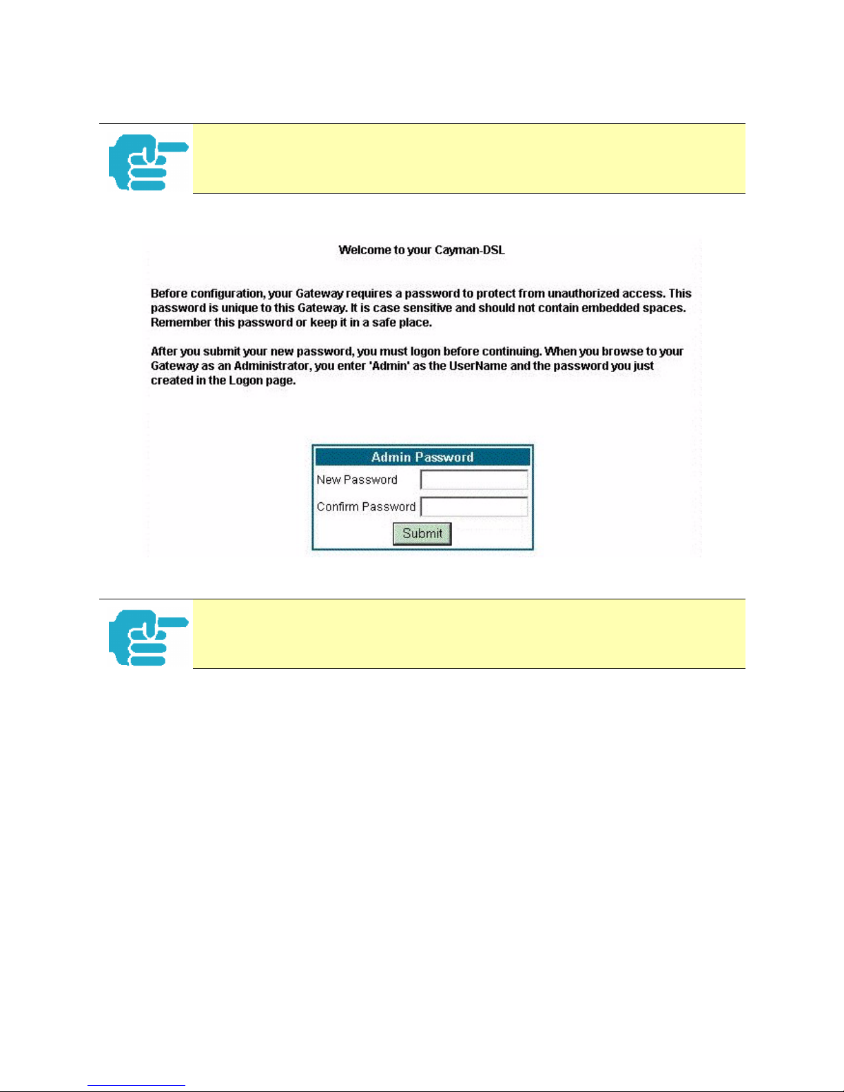
Section 4 Configure
If your admin password is not set, you will be prompted to set it before you reach
the Home page.
This completes the UPGRADE process for COS 6.3.
92
Page 93

Section 4 Configure
Install Keys
Link
Response
Comment
Install Keys
You can obtain advanced product functionality by employing a software Feature Key. Software feature keys are specific to a Gateway's
serial number. Once the feature key file is installed and the Gateway
is restarted, the new feature's functionality becomes enabled.
Use Cayman Software Feature Keys
Background
Cayman Gateway users obtain advanced product functionality by installing a software feature key . This concept utilizes a specially constructed and
distributed file (referred to as a feature key) to enable additional capability
within the unit.
Software feature key properties are:
Specific to a unit’s serial number
•
– They will not be accepted on a platform with another serial number.
Once installed, and the Gateway restarted, the new feature’s functionality
becomes available. This allows full access to configuration, operation,
maintenance and administration of the new enhancement.
Software feature keys for COS 6.3 enable these enhancements:
Security Monitoring Log
•
93
Page 94
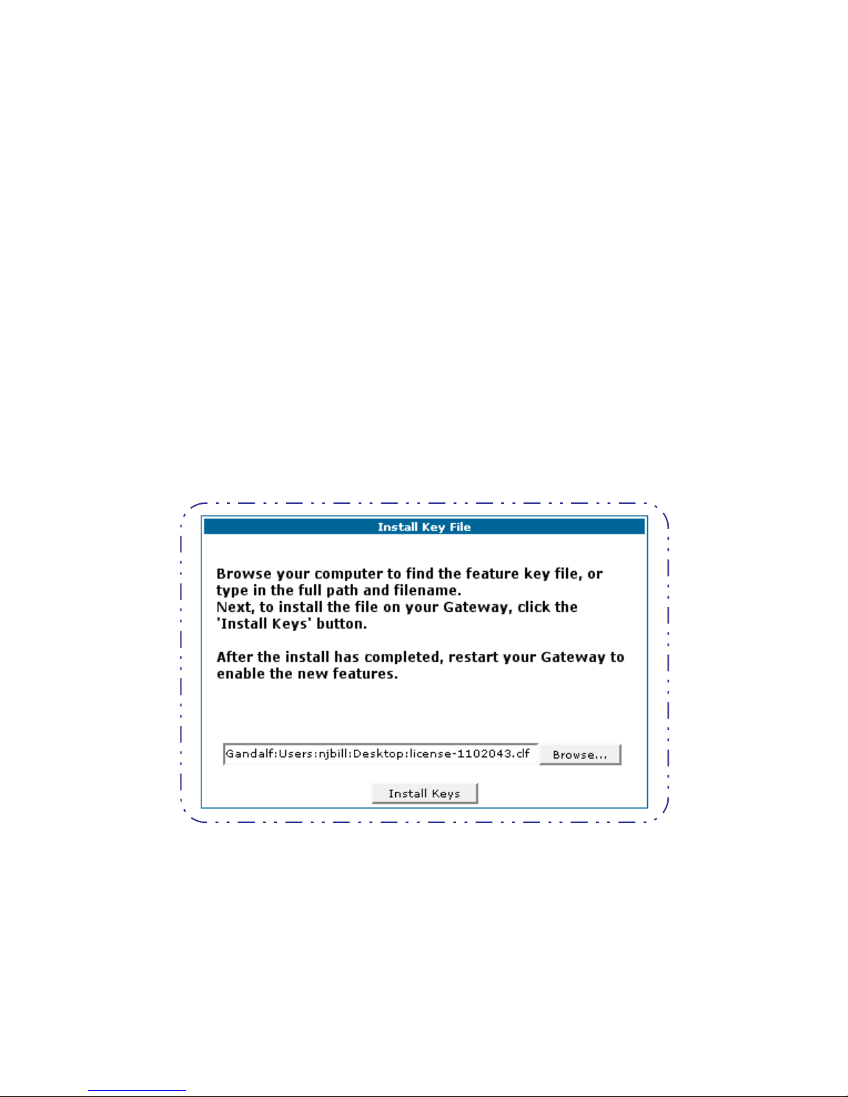
Section 4 Configure
BreakWater Basic Firewall
•
• BarrierReef Advanced Firewall
• SafeHarbour IPSec Tunnel at the Gateway
Obtaining Software Feature Keys
Contact your Service Provider to acquire a Software Feature Key.
Procedure - Install a New Feature Key File
With the appropriate feature key file resident on your LAN PC, use the steps
listed below to enable a new function.
Step 1 From the Home page, click the
Step 2 Click
Step 3 Enter the feature key file name in the input Text Box.
Install Keys
The Install Key File page appears.
Install
toolbar button.
• Browse your drive for the file, or
• Type the full path and file name in the Text Box.
Step 4 Click the
Install Keys
button.
94
Page 95

Section 4 Configure
Step 5 Click the
The Confirmation screen appears.
Restart
toolbar button.
Step 6 Click the
Restart the Gateway
To check your installed features:
Step 1 Click the
Step 2 Click the
Install
List of Features
link to confirm.
toolbar button.
link.
95
Page 96

Section 4 Configure
The System Status page appears with the information from the features
link displayed below. You can check that the feature you just installed is
enabled.
96
Page 97

Troubleshoot
Troubleshoot
Button
Troubleshoot
This section provides some specific procedures and tips for working with
important features of Cayman OS 6.3.
request this information.
Automated Multi-Layer Diagnostics
Step 1 Click the
Step 2 Click the
Perform Tr oubleshooting on Gateways
There are three major T roubleshooting capabilities you can
access via your Cayman Gateway’s web interface. The procedures for using them are discussed here. In the event of a
problem with your system, your Service Provider may
Troubleshoot
Diagnostics
toolbar button.
link.
Step 3 Click the
Run Diagnostics
link.
97
Page 98

Troubleshoot
Each test generates one of the following result codes:
CODE Description
PASS The test was successful.
FAIL The test was unsuccessful.
SKIPPED The test was skipped because a test on which it depended failed,
or it was not supported by the service provider equipment to
which it is connected.
PENDING The test timed out without producing a result. Try running the
test again.
WARNING The test was unsuccessful. The Service Provider equipment your
Gateway connects to may not support this test.
98
Page 99
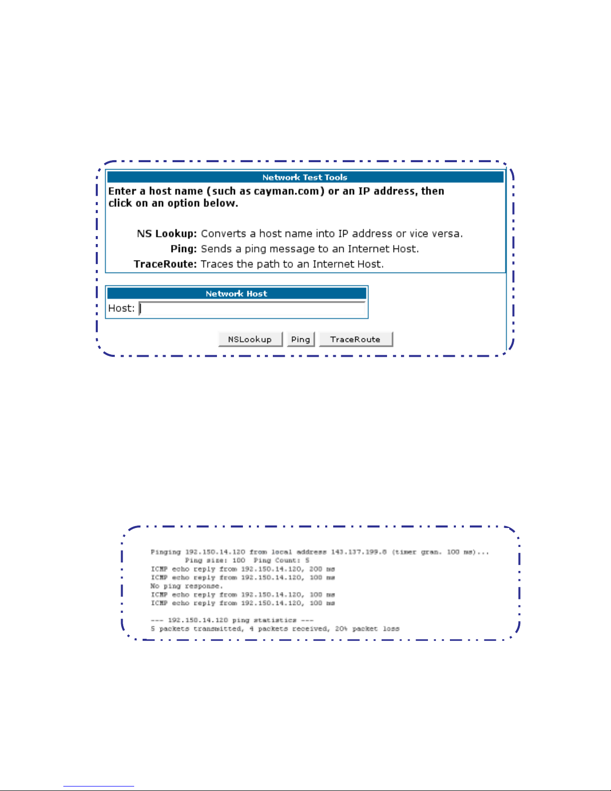
Network Tools
Use these steps:
Troubleshoot
Step 1 Click the
Step 2 Click the
Three test tools are available from this page.
• NSLookup - converts a domain name to its IP address and vice versa.
Troubleshoot
Network Tools
toolbar button.
link.
• Ping - tests the “reachability” of a particular network destination by
sending an ICMP echo request and waiting for a reply.
• TraceRoute - displays the path to a destination by showing the num-
ber of hops and the router addresses of these hops.
Step 3 To use the Ping capability, type a destination address (domain name or IP
address) in the text box and click the
Example: Ping to grosso.com.
Result: The host was reachable with four out of five packets sent.
Step 4 To use the TraceRoute capability, type a destination address (domain name
or IP address) in the text box and click the
Ping
button.
TraceRoute
button.
99
Page 100

Example: Show the path to the grosso.com site.
Troubleshoot
Result: It took 20 hops to get to the grosso.com web site.
Step 5 To use the NSLookup capability, type an address (domain name or IP
address) in the text box and click the
NSLookup
button
Example: Show the IP Address for grosso.com
Result: The DNS Server doing the lookup is displayed in the Server: and
Address: fields. If the Name Server can find your entry in its table, it is displayed
in the Name: and Address: fields.
100
 Loading...