

Page 1
ProSafe Wireless-N VPN
Firewall SRXN3205
Reference Manual
NETGEAR, Inc.
350 East Plumeria Drive
San Jose, CA 95134
202-10416-02
v1.0
January 2010
Page 2

© 2008–2010 by NETGEAR, Inc. All rights reserved..
Technical Support
Please refer to the support information card that shipped with your product. By registering your product at
http://www.netgear.com/register, we can provide you with faster expert technical support and timely notices of
product and software upgrades.
NETGEAR, INC. Support Information
Phone: 1-888-NETGEAR, for US & Canada only. For other countries, see your Support information card.
E-mail: support@netgear.com
North American NETGEAR website:
http://www.netgear.com
Trademarks
NETGEAR and the NETGEAR logo are registered trademarks and ProSafe is a trademark of NETGEAR, Inc.
Microsoft, Windows, and Windows NT ar e registered trademarks of Microsoft Corporation. Other brand and product
names are registered trademarks or trademarks of their respective holders.
Statement of Conditions
In the interest of improving internal design, operational function, and/or reliability, NETGEAR reserves the right to
make changes to the products described in this document without notice.
NETGEAR does not assume any liability that may occur due to the use or application of the product(s) or circuit
layout(s) described herein.
Federal Communications Commission (FCC) Compliance Notice: Radio Frequency
Notice
This equipment has been tested and found to comply with the limits for a Class B digital device, pursuant to
part 15 of the FCC Rules. These limits are designed to provide reasonable protection against harmful interference in a
residential installation. This equipment generates, uses, and can radiate radio frequency energy and, if not installed and
used in accordance with the instruct ions, may cause harmf ul interference to radio communications. However, there is no
guarantee that interference will not occur in a particular installation. If this equipment does cause harmful interference to
radio or television reception, which can be determined by turning the equipment off and on, the user is encouraged to try
to correct the interference by one or more of the following measures:
• Reorient or relocate the receiving antenna.
• Increase the separation between the equipment and receiver.
• Connect the equipment into an outlet on a circuit different from that to which the receiver is connected.
• Consult the dealer or an experienced radio/TV technician for help.
EU Regulatory Compliance Statement
The ProSafe Wireless-N VPN Firewall is compliant with the following EU Council Directives: 89/336/EEC and LVD
73/23/EEC. Compliance is verified by testing to the following standards: EN55022 Class B, EN55024 and EN60950-1.
For EU Declaration of Conformity please visit:
ii
http://kb.netgear.com/app/answers/detail/a_id/11621/sno/0.
v1.0, January 2010
Page 3

Bestätigung des Herstellers/Importeurs
Es wird hiermit bestätigt, daß das ProSafe Wireless-N VPN Firewall gemäß der im BMPT-AmtsblVfg 243/1991 und Vfg
46/1992 aufgeführten Bestimmungen entstört ist. Das vorschriftsmäßige Betreiben einiger Geräte (z.B. Testsender) kan n
jedoch gewissen Beschränkungen unterliegen. Lesen Sie dazu bitte die Anmerkungen in der Betriebsanleitung.
Das Bundesamt für Zulassungen in der Telekommunikation wurde davon unterrichtet, daß dieses Gerät auf den Markt
gebracht wurde und es ist berechtigt, die Serie auf die Erfüllung der Vorschriften hin zu überprüfen.
Certificate of the Manufacturer/Importer
It is hereby certified that the ProSafe Wireless-N VPN Firewall has been suppressed in accordance with the conditions
set out in the BMPT-AmtsblVfg 243/1991 and Vfg 46/1992. The operation of some equipment (for example, test
transmitters) in accordance with the regulations may, however, be subject to certain restrictions. Please refer to the notes
in the operating instructions.
Federal Office for Telecommunications Approvals has been notified of the placing of this equipment on the market
and has been granted the right to test the series for compliance with the regulations.
Voluntary Control Council for Interference (VCCI) Statement
This equipment is in the second category (information equipment to be used in a residential area or an adjacent area
thereto) and conforms to the standards set by the Voluntary Control Council for Interference by Data Processing
Equipment and Electronic Office Machines aimed at preventing radio interference in such residential areas.
When used near a radio or TV receiver , it may become the cause of radio interference.
Read instructions for correct handling.
Additional Copyrights
AES Copyright (c) 2001, Dr Brian Gladman <brg@gladman.uk.net>, Worcester, UK.
All rights reserved.
TERMS
Redistribution and use in source and binary forms, with or without modification, are permitted
subject to the following conditions:
1. Redistributions of source code must retain the above copyright notice, this list of
conditions and the following disclaimer.
2. Redistributions in binary form must reproduce the above copyright notice, this list of
conditions and the following disclaimer in the documentation and/or other materials
provided with the distribution.
3. The copyright holder's name must not be used to endorse or promote any products
derived from this software without his specific prior written permission.
This software is provided 'as is' with no express or implied warranties of correctness or fitness
for purpose.
v1.0, January 2010
iii
Page 4

Open SSL Copyright (c) 1998-2000 The OpenSSL Project. All rights reserved.
Redistribution and use in source and binary forms, with or without modification, are permitted
provided that the following conditions * are met:
1. Redistributions of source code must retain the above copyright notice, this list of conditions
and the following disclaimer.
2. Redistributions in binary form must reproduce the above copyright notice, this list of
conditions and the following disclaimer in the documentation and/or other materials
provided with the distribution.
3. All advertising materials mentioning features or use of this software must display the
following acknowledgment: “This product includes software developed by the OpenSSL
Project for use in the OpenSSL Toolkit. (http://www.openssl.org/)”
4. The names "OpenSSL Toolkit" and "OpenSSL Project" must not be used to endorse or
promote products derived from this software without prior written permission. For written
permission, please contact openssl-core@openssl.org.
5. Products derived from this software may not be called "OpenSSL" nor may "OpenSSL"
appear in their names without prior written permission of the OpenSSL Project.
6. Redistributions of any form whatsoever must retain the following acknowledgment: "This
product includes software developed by the OpenSSL Project for use in the OpenSSL
Toolkit (http://www.openssl.org/)"
THIS SOFTWARE IS PROVIDED BY THE OpenSSL PROJECT ``AS IS'' AND ANY
EXPRESSED OR IMPLIED WARRANTIES, INCLUDING, BUT NOT LIMITED TO, THE
IMPLIED WARRANTIES OF MERCHANTABILITY AND FITNESS FOR A PARTICULAR
PURPOSE ARE DISCLAIMED. IN NO EVENT SHALL THE OpenSSL PROJECT OR ITS
CONTRIBUTORS BE LIABLE FOR ANY DIRECT, INDIRECT, INCIDENTAL, SPECIAL,
EXEMPLARY, OR CONSEQUENTIAL DAMAGES (INCLUDING, BUT NOT LIMITED TO,
PROCUREMENT OF SUBSTITUTE GOODS OR SERVICES; LOSS OF USE, DATA, OR
PROFITS; OR BUSINESS INTERRUPTION) HOWEVER CAUSED AND ON ANY THEORY
OF LIABILITY, WHETHER IN CONTRACT, STRICT LIABILITY, OR TORT (INCLUDING
NEGLIGENCE OR OTHERWISE) ARISING IN ANY WAY OUT OF THE USE OF THIS
SOFTWARE, EVEN IF ADVISED OF THE POSSIBILITY OF SUCH DAMAGE.
This product includes cryptographic software written by Eric Young (eay@cryptsoft.com). This
product includes software written by Tim Hudson (tjh@cryptsoft.com).
MD5 Copyright (C) 1990, RSA Data Security, Inc. All rights reserved.
License to copy and use this software is granted provided that it is identified as the "RSA Data
Security, Inc. MD5 Message-Digest Algorithm" in all material mentioning or referencing this
software or this function. License is also granted to make and use derivative works provided
that such works are identified as "derived from the RSA Data Security, Inc. MD5 MessageDigest Algorithm" in all material mentioning or referencing the derived work.
RSA Data Security, Inc. makes no representations concerning either the merchantability of
this software or the suitability of this software for any particular purpose. It is provided "as is"
without express or implied warranty of any kind.
These notices must be retained in any copies of any part of this documentation and/or
software.
iv
v1.0, January 2010
Page 5

PPP Copyright (c) 1989 Carnegie Mellon University. All rights reserved.
Redistribution and use in source and binary forms are permitted provided that the above
copyright notice and this paragraph are duplicated in all such forms and that any
documentation, advertising materials, and other materials related to such distribution and use
acknowledge that the software was developed by Carnegie Mellon University. The name of
the University may not be used to endor se or promote products derived from thi s software
without specific prior written permission.
THIS SOFTWARE IS PROVIDED ``AS IS'' AND WITHOUT ANY EXPRESS OR IMPLIED
WARRANTIES, INCLUDING, WITHOUT LIMITATION, THE IMPLIED WARRANTIES OF
MERCHANTIBILITY AND FITNESS FOR A PARTICULAR PURPOSE.
Zlib zlib.h -- interface of the 'zlib' general purpose compression library version 1.1.4, March 11th,
2002. Copyright (C) 1995-2002 Jean-loup Gailly and Mark Adler.
This software is provided 'as-is', without any express or implied warranty. In no event will the
authors be held liable for any damages arising from the use of this software. Permission is
granted to anyone to use this software for any purpose, including commercial applications,
and to alter it and redistribute it freely, subject to the following restrictions:
1. The origin of this software must not be misrepresented; you must not claim that you wrote
the original software. If you use this software in a product, an acknowledgment in the
product documentation would be appreciated but is not required.
2. Altered source versions must be plainly marked as such, and must not be misrepresented
as being the original software.
3. This notice may not be removed or altered from any source distribution.
Jean-loup Gailly: jloup@gzip.org; Mark Adler: madler@alu mni.caltech.edu
The data format used by the zlib library is described by RFCs (Request for Comments) 1950
to 1952 in the files ftp://ds.internic.net/rfc/rfc1950.txt
and rfc1952.txt (gzip format)
(zlib format), rfc1951.txt (deflate format)
Product and Publication Details
Model Number: SRXN3205
Publication Date: January 2010
Product Family: VPN Firewall
Product Name: ProSafe Wireless-N VPN Firewall
Home or Business Product: Business
Language: English
Publication Part Number: 202-10416-02
Publication Version Number 1.0
v1.0, January 2010
v
Page 6

vi
v1.0, January 2010
Page 7

ProSafe Wireless-N VPN Firewall SRXN3205 Reference Manual
Contents
ProSafe Wireless-N VPN Firewall SRXN3205 Reference Manual
About This Manual
Conventions, Formats, and Scope ..................................................................................xiii
How to Print this Manual ..................................................................................................xiv
Revision History ..................... ... .......................................... ... ..........................................xiv
Chapter 1
Introduction
Key Features ..................................................................................................................1-1
A Powerful, True Firewall with Content Filtering ......................................................1-2
Autosensing Ethernet Connections with Auto Uplink ...............................................1-2
Extensive Protocol Support ......................................................................................1-3
Advanced VPN Support for Both IPsec and SSL .....................................................1-3
Wireless Networking Features ............................ ... ... .... ... ... ... ....... ... ... .... ... ... ... ... .... ... ... ..1-4
Easy Installation and Management ................................................................................1-5
System Requirements .. ... .......................................... ... .......................................... ..1-5
Package Contents ..........................................................................................................1-6
Front Panel Features ......................................................................................................1-6
Rear Panel Features ......................................................................................................1-8
Default IP Address, Login Name, and Password Location ........................... .................. 1-9
Qualified Web Browsers .................................................................................................1-9
Chapter 2
Connecting to the Internet (WAN)
Understanding the Connection Steps .............................................................................2-1
Logging into the VPN Firewall ........................................................................................2-2
Navigating the Menus .....................................................................................................2-3
Configuring the Internet Connection (WAN) ........................................................... ... ... ..2-4
Automatically Detecting and Connecting ........................ .... ... ... ...............................2-4
Manually Configuring the Internet Connection ............................................. .... ........ 2-7
v1.0, January 2010
vii
Page 8

ProSafe Wireless-N VPN Firewall SRXN3205 Reference Manual
Configuring the WAN Mode ...................................................................................2-11
Configuring Dynamic DNS ...........................................................................................2-12
Configuring the Advanced WAN Options (Optional) ............................................... ...... 2-14
Additional WAN Related Configuration ..................................................................2-15
Chapter 3
LAN Configuration
Using the VPN Firewall as a DHCP Server .. ... ... ... ... .... ... ... ... .... ... ... ... ....... ... ... ... .... ... ... ..3-1
Configuring the LAN Setup Options ...............................................................................3-2
Managing Groups and Hosts (LAN Groups) ...................................................................3-5
Viewing the LAN Groups Database .........................................................................3-7
Adding Devices to the LAN Groups Database ......................................................... 3-8
Changing Group Names in the LAN Groups Database ...........................................3-9
Configuring DHCP Address Reservation .................................................................3-9
Configuring Multi Home LAN IP Addresses ..................................................................3-10
Configuring Static Routes .............................................................................................3-11
Configuring Routing Information Protocol (RIP) ........................................................ ...3-13
Chapter 4
Wireless Configuration
Wireless Equipment Placement and Range Guidelines ..................................... ............4-2
Understanding the VPN Firewall Wireless Security Options ..........................................4-2
Configuring Basic Wireless Setup (Without Security) ................... ................ ..................4-4
Testing and Completing Wireless Set up (Without Security) ................... ... ... ... ....... ... ... ..4-6
Testing Wireless Connectivity (Without Security) .....................................................4-6
Configuring the Wireless Channel Settings (Without Security) ................................4-7
Wireless Security Types and Settings ............................................. ... .... ... ... ...... .... ... ... ..4-8
SSID and WEP/WPA Settings Setup Form ..............................................................4-9
Configuring WEP Security ......................................................................................4-11
Configuring WPA Security Without RADIUS ..........................................................4-12
Configuring WPA Security with RADIUS ................................................................4-13
Verifying Wireless Connectivity (With Security) .....................................................4-16
Deploying the VPN Firewall ...................................................................................4-16
Configuring Advanced Wireless Settings .....................................................................4-17
Restricting Wireless Access by MAC Address .............................................................4-18
viii
v1.0, January 2010
Page 9

ProSafe Wireless-N VPN Firewall SRXN3205 Reference Manual
Chapter 5
Firewall Security and Content Filtering
About Firewall Security and Content Filtering ................................................................5-1
Using Rules & Services to Block or Allow Traffic ............................................................5-2
Services-Based Rules .. .......................................... ... .......................................... .....5-2
Viewing the Firewall Rules .......................................................................................5-7
Order of Precedence for Rules ................................................................................5-7
Setting the Outbound Policy ................................... .......................................... ... .....5-7
Creating a LAN WAN Outbound Services Rule .......................................................5-8
Creating a LAN WAN Inbound Services Rule ..........................................................5-9
Modifying Rules ......................................................................................................5-10
Inbound Rules Examples .......................................................................................5-11
Outbound Rules Example ............................ ... ... .......................................... .... ...... 5-14
Configuring Other Firewall Features .............................................................................5-14
Attack Checks .................... ... .... .......................................... ...................................5-14
Configuring Session Limits .....................................................................................5-17
Managing the Application Level Gateway for SIP Sessions ..................................5-18
Creating Services, QoS Profiles, and Bandwidth Profiles ............................................5-19
Adding Customized Services .................................................................................5-19
Setting Quality of Service (QoS) Priorities ............................................................. 5-21
Creating Bandwidth Profiles ...... ... ... ... ....................................................................5-21
Setting Schedules to Block or Allow Specific Traffic .................................................. ...5-24
Blocking Internet Sites (Content Filtering) ....................................................................5-25
Enabling Source MAC Filtering (Address Filtering) ...................................................... 5-28
Configuring IP/MAC Address Binding ...........................................................................5-29
Configuring Port Triggering ...........................................................................................5-31
Configuring UPnP (Universal Plug and Play) ...............................................................5-34
E-Mail Notifications of Event Logs and Alerts ......................................... ......................5-35
Administrator Tips .........................................................................................................5-36
Chapter 6
Virtual Private Networking Using IPsec
Using the VPN Wizard for Client and Gateway Configurations ...................................... 6-1
Creating Gateway to Gateway VPN Tunnels with the Wizard ........................................6-2
Creating a Client to Gateway VPN Tunnel with the Wizard ............................................6-5
Creating a VPN Client to VPN Firewall Connection ..................... ... ... .... ... ... ... ... .... ...... ..6-6
v1.0, January 2010
ix
Page 10

ProSafe Wireless-N VPN Firewall SRXN3205 Reference Manual
Configuring the VPN Firewall .......... ... .... ... .......................................... ... ..................6-7
Configuring the VPN Client .......................... ... ... .......................................... .... ........ 6-7
Testing the Connection ...........................................................................................6-10
Viewing VPN Firewall VPN Connection Status and Logs .............................................6-11
Managing IPsec VPN Policies ..... .... ... ... ... .... ................................................................6-12
Managing IKE Polices ............... ... ... .......................................... .............................6-12
Configuring VPN Policies .......................................................................................6-20
Assigning IP Addresses to Remote Users (Mode Config) ............................................6-27
Mode Config Operation ...... ... .... ... .......................................... ... .............................6-28
Configuring Mode Config Operation on the VPN Firewall ......................................6-28
Configuring Mode Config Operation on the VPN Client .........................................6-32
Configuring Extended Authentication (XAUTH) ............................................................6-33
Configuring XAUTH for VPN Clients ......................................................................6-34
User Database Configuration .... ... ... .......................................... .............................6-35
RADIUS Client Configuration .................................................................................6-35
Configuring Keepalives and Dead Peer Detection .......................................................6-37
Configuring Keepalives ..........................................................................................6-38
Configuring Dead Peer Detection ..........................................................................6-39
Configuring NetBIOS Bridging with VPN ......................................................................6-40
Chapter 7
Virtual Private Networking Using SSL
Understanding the Portal Options ...................................................................................7-1
Planning for SSL VPN ....................................................................................................7-2
Creating the Portal Layout ..............................................................................................7-3
Configuring Domains, Groups, and Users ......................................................................7-7
Configuring Applications for Port Forwarding ..................................... .... ... ... ... ... .... ........ 7-8
Adding Servers ................................... .......................................... ............................7-8
Adding A New Host Name ................................. .... ... ... ... .... ... ..................................7-9
Configuring the SSL VPN Client ...................................................................................7-10
Configuring the Client IP Address Range ........................................... ... ... ... .... ... ...7-11
Adding Routes for VPN Tunnel Clients ........... ... .... ... ... ... .... ... ... ... .... ... ... ... ... .... ... ...7-12
Using Network Resource Objects to Simplify Policies ..................................................7-13
Adding New Network Resources ..........................................................................7-13
Configuring User, Group, and Global Policies ..............................................................7-15
Viewing Policies .....................................................................................................7-17
x
v1.0, January 2010
Page 11

ProSafe Wireless-N VPN Firewall SRXN3205 Reference Manual
Adding a Policy ............................... ... .... ... ... .......................................... ................7-18
Chapter 8
Managing Users, Authentication, and Certificates
Adding Authentication Domains, Groups, and Users .....................................................8-1
Creating a Domain .......................... ... .... .......................................... ... .....................8-1
Creating a Group .................................... .......................................... ... .....................8-5
Creating a New User Account ... ... ... .......................................... ... ............................8-6
Setting User Login Policies .......................... ... ... .......................................... ............8-7
Changing Passwords and Other User Settings ......................... ....... ...... ...... ....... .....8-9
Managing Certificates ......................... ... ... .......................................... ..........................8-11
Viewing and Loading CA Certificates .....................................................................8-12
Viewing Active Self Certificates ..............................................................................8-13
Obtaining a Self Certificate from a Certificate Authority ......................... ... ... .... ...... 8-14
Managing your Certificate Revocation List (CRL) .. ... ... ..........................................8-17
Chapter 9
VPN Firewall and Network Management
Performance Management .................................... ... .... .......................................... ... .....9-1
Bandwidth Capacity ........................ ... .... ... .......................................... .....................9-1
Features that Reduce Traffic ....................................................................................9-2
Features that Increase Traffic ...................... ... ... .......................................... .... ........ 9-4
Using QoS to Shift the Traffic Mix ............................................................................9-7
Tools for Traffic Management ........................................................................... ... .....9-7
Changing Passwords and Administrator Settings . ... .... .......................................... ... .....9-8
Enabling Remote Management Access .........................................................................9-9
Using an SNMP Manager .............................................................................................9-12
Managing the Configuration File ...................................................................................9-14
Configuring Date and Time Service ..............................................................................9-17
Chapter 10
Monitoring System Performance
Activating Notification of Events and Alerts ..................................................................10-1
Viewing the Logs ..........................................................................................................10-4
Enabling the Traffic Meter .............................................................................................10-5
Viewing VPN Firewall Configuration and System Status ..............................................10-8
Monitoring VPN Firewall Statistics ......... ... .... ... ... ... ... .... .......................................... ... .10-10
Monitoring the WAN Port Status .................................................................................10-10
v1.0, January 2010
xi
Page 12

ProSafe Wireless-N VPN Firewall SRXN3205 Reference Manual
Monitoring Attached Devices ......................................................................................10-11
Viewing the DHCP Log ...............................................................................................10-13
Monitoring Active Users ................... ... ... ... .......................................... .... ....................10-14
Viewing the Port Triggering Status .............................................................................10-14
Monitoring the VPN Tunnel Connection Status ..........................................................10-15
Viewing the VPN Logs ................................................................................................10-17
Chapter 11
Troubleshooting
Basic Functions ............................................................................................................11- 1
Power LED Not On .................................................................................................11-2
LEDs Never Turn Off ..............................................................................................11-2
LAN or WAN Port LEDs Not On .............................................................................11-2
Troubleshooting the Web Configuration Interface ........................................................11-3
Troubleshooting the ISP Connection ............................................................................11-4
Troubleshooting a TCP/IP Network Using a Ping Utility ...............................................11-5
Testing the LAN Path to Your VPN Firewall ...........................................................11-5
Testing the Path from Your PC to a Remote Device ..............................................11-6
Restoring the Default Configuration and Password ............ ... .... ... ... ... ..........................11-7
Problems with Date and Time .......................................................................................11-7
Using the Diagnostics Utilities ......................................................................................11-8
Appendix A
Default Settings and Technical Specifications
Default Settings ............................................................................................................. A-1
Technical Specifications ................................................................................................. A-3
Appendix B
Two Factor Authentication
Why do I need Two-Factor Authentication? ................................................................... B-1
What are the benefits of Two-Factor Authentication? ............................................. B-1
What is Two-Factor Authentication ......................................................................... B-2
NETGEAR Two-Factor Authentication Solutions ....................................................... .... B-2
Appendix C
Related Documents
Index
xii
v1.0, January 2010
Page 13
ProSafe Wireless-N VPN Firewall SRXN3205 Reference Manual
About This Manual
The NETGEAR® ProSafe™ Wireless-N VPN FirewallReference Manual describes how to
configure and troubleshoot a ProSafe Wireless-N VPN Firewall. The informatio n in this manual is
intended for readers with intermediate computer and networking skills.
Conventions, Formats, and Scope
The conventions, formats, and scope of this manual are described in the following paragraphs:
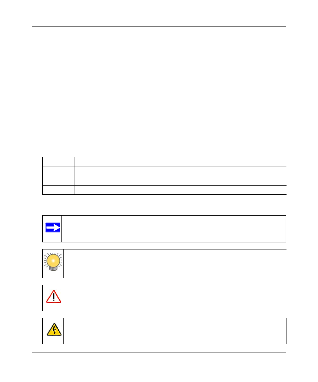
• Typographical Conventions. This manual uses the following typographical conventions:
Italic Emphasis, books, CDs, file and server names, extensions
Bold User input, IP addresses, GUI screen text
Fixed Command prompt, CLI text, code
italic URL links
• Formats. This manual uses the following formats to highlight special messages:
Note: This format is used to highlight information of importance or special interest.
Tip: This format is used to highlight a procedure that will save time or resources.
Warning: Ignoring this type of note may result in a malfunction or damage to the
equipment.
Danger: This is a safety warning. Failure to take heed of this notice may result in
personal injury or death.
v1.0, January 2010
xiii
Page 14
ProSafe Wireless-N VPN Firewall SRXN3205 Reference Manual
• Scope. This manual is written for the VPN firewall according to these specifications:
Product ProSafe Wireless-N VPN Firewall
Manual Publication Date January 2010
For more information about network, Internet, firewall, and VPN technologies, see the links to the
NETGEAR website in Appendix C, “Related Documents.”.
Note: Product updates are available on the NETGEAR, Inc. website at
http://kbserver.netgear.com/products/SRXN3205.asp.
How to Print this Manual
T o print this manual, your computer must have the free Adobe Acrobat reader installed in order to
view and print PDF files. The Acrobat reader is available on the Adobe websit e at
http://www.adobe.com.
Tip: If your printer supports printing two pages on a single sheet of paper, you can save
paper and printer ink by selecting this feature.
Revision History
Manual Part
Number
202-10416-01 1.0 October 2008 First publication
202-10416-02 1.0 January 2009 Added the following ne w features for the January 2010 firmware
xiv
Manual
Version
Number
Publication
Date
Description
maintenance release:
• Connection reset and delay options on the WAN ISP Settings
screen (see “Manually Configuring the Internet Connection”).
• Support for DNS 3322 in the Dynamic DNS submenu (see
“Configuring Dynamic DNS”).
v1.0, January 2010
Page 15

ProSafe Wireless-N VPN Firewall SRXN3205 Reference Manual
202-10416-02
(continued)
1.0 January 2009 (continued)
• Support for an address range for inbound LAN rules on the Add
LAN WAN Inbound Service screen (see “Inbound Rules (Port
Forwarding)” and “Creating a LAN WAN Inbound Services Rule”).
• Support for new log options such as Resolved DNS Names and
VPN on the Firewall Logs & E-mail screen (see “Activating
Notification of Events and Alerts”).
In addition, made the following substantial changes to the book:
• Provided new captures for most screens and resized the existing
screen captures for better viewing.
• Made global stylistic changes for consistency and clarity.
• Revised the following sections in Chapter 2, “Connecting to the
Internet (WAN)”:
* “Configuring the Internet Connection (WAN)”
* “Configuring Dynamic DNS”
• Revised the following sections in Chapter 3, “LAN Configuration”:
* “Using the VPN Firewall as a DHCP Server”
* “Configuring the LAN Setup Options”
• Reorganized Chapter 4, “Wireless Configuration,” and revised
the following sections in this chapter:
* “Understanding the VPN Firewall Wireless Security Options”
* “Configuring Basic Wireless Setup (Without Security)”
* “Wireless Security Types and Settings”
* “Configuring Advanced Wireless Settings”
* “Restricting Wireless Access by MAC Address”
• Added the “Configuring Other Firewall Features” section to
Chapter 5, “Firewall Security and Content Filtering,” and revised
the following sections in this chapter:
* “Using Rules & Services to Block or Allow Traffic”
* “Creating Services, QoS Profiles, and Bandwidth Profiles”
* “Setting Schedules to Block or Allow Specific Traffic”
* “Blocking Internet Sites (Content Filtering)”
* “Enabling Source MAC Filtering (Address Filtering)”
* “Configuring IP/MAC Address Binding”
* “Configuring Port Triggering”
* “E-Mail Notifications of Event Logs and Alerts”
v1.0, January 2010
xv
Page 16

ProSafe Wireless-N VPN Firewall SRXN3205 Reference Manual
202-10416-02
(continued)
1.0 January 2009 (continued)
• Reorganized Chapter 6, “Virtual Private Networking Using IPsec,
added the “Viewing VPN Firewall VPN Connection Status and
Logs,” “Configuring Keepalives and Dead Peer Detection,” and
“Configuring NetBIOS Bridging with VPN” sections, and revised
the following sections in this chapter:
* “Using the VPN Wizard for Client and Gateway
Configurations”
* “Creating Gateway to Gateway VPN Tunnels with the Wizard”
* “Managing IPsec VPN Policies”
* “Assigning IP Addresses to Remote Users (Mode Config)”
* “Configuring Extended Authentication (XAUTH)”
• Made minor changes in Chapter 7, “Virtual Private Networking
Using SSL.”
• Revised the following sections in Chapter 8, “Managing Users,
Authentication, and Certificates:
* “Adding Authentication Domains, Groups, and Users”
* “Managing Certificates”
• Revised the following sections in Chapter 9, “VPN Firewall and
Network Management”:
* “Enabling Remote Management Access”
* “Managing the Configuration File”
• Revised the following sections in Chapter 10, “Monitoring System
Performance”:
* “Activating Notification of Events and Alerts”
* “Viewing the Logs”
* “Viewing VPN Firewall Configuration and System Status”
* “Monitoring the WAN Port Status”
* “Monitoring Attached Devices”
* “Viewing the VPN Logs”
• Revised the following sections in Chapter 11, “Troubleshooting
* “Troubleshooting the ISP Connection”
* “Troubleshooting a TCP/IP Network Using a Ping Utility”
* “Restoring the Default Configuration and Password”
• Added Appendix B, “Two Factor Authentication”
xvi
v1.0, January 2010
Page 17

ProSafe Wireless-N VPN Firewall SRXN3205 Reference Manual
Chapter 1
Introduction
The ProSafe Wireless-N VPN Firewall SRXN3205 provides Internet connectivity to your local
Ethernet and wireless networks via a broadband cable or DSL modem. The SRXN3205 is a
complete security solution with a powerful and flexible firewall to safeguard your networks along
with advanced IPsec and SSL VPN technologies for secure wired and wireless connections.
Moreover, the ProSafe Wireless-N VPN Firewall supports wireless connections over the wider
range and more robust connections afforded by 802.11N and 802.11a wireless networks. The
SRXN3205 also supports wireless bridging.
The Gigabit Ethernet LAN ports and WAN port ensure extremely high data transfer speeds.
The SRXN3205 is a plug-and-play device that can be installed and configured within minute s.
This chapter contains the following sections:
• “Key Features” on this page
• “Wireless Networking Features” on page 1-4
• “System Requirements” on page 1-5
• “Package Contents” on page 1-6
• “Front Panel Features” on page 1-6
• “Rear Panel Features” on page 1-8
• “Default IP Address, Login Name, and Password Location” on page 1-9
• “Qualified Web Browsers” on page 1-9
Key Features
The SRXN3205 provides the following key features:
• A single 10/100/1000 Mbps Gigabit Ethernet WAN port for your Internet connection.
• Built-in four-port 10/100/1000 Mbps Gigabit Ethernet LAN switch for extremely fast data
transfer between local network resources and all of the wireless clients.
• Advanced IPsec and SSL VPN support
Introduction 1-1
v1.0, January 2010
Page 18

ProSafe Wireless-N VPN Firewall SRXN3205 Reference Manual
• Advanced stateful packet inspection (SPI) firewall with multi-NAT support
• Easy, web-based setup for installation and management
• Front panel LEDs for easy monitoring of status and activity
• Flash memory for firmware upgrade
• AC-DC power adapter for low current draw
A Powerful, True Firewall with Content Filtering
Unlike simple Internet sharing NAT routers, the SRXN3205 is a true firewall, using stateful packet
inspection (SPI) to defend against hacker attacks. Its firewall features include:
• Automatically detects and thwarts denial of service (DoS) attacks such as Ping of Death and
SYN Flood.
• Blocks unwanted traffic from the Internet to your LAN.
• Blocks access from your LAN to Internet locations or services that you specify as off-limits.
• Prevents objectionable content from reaching your PCs. You can control access to Internet
content by screening for Web services, Web addresses, and keywords within Web addresses.
You can configure the firewall to log and report attempts to access objectionable Internet sites.
• Permits scheduling of firewall policies by day and time.
• Logs security events such as blocked incoming traffic, port scans, attacks, and administrator
logins. You can configure the firewall to e-mail the log to you at specified intervals. You can
also configure the firewall to send immediate alert messages to your e-mail address or e-mail
pager whenever a significant event occurs.
Autosensing Ethernet Connections with Auto Uplink
With its internal 5-port 10/100/1000 Mbps switch and 10/100/1000 W AN port, the SRXN3205 can
connect to either a 10 Mbps standard Ethernet network, a 100 Mbps Fast Ethernet network, or a
1000 Mbps Gigabit Ethernet network. The five LAN and WAN interfaces are autosensing and
capable of full-duplex or half-duplex operation.
TM
The SRXN3205 incorporates Auto Uplink
sense whether the Ethernet cable plugged into the port should have a “normal” connection such as
to a PC or an “uplink” connection such as to a switch or hub. That port will then configure itself to
the correct configuration. This feature eliminates the need to worry about crossover cables, as
Auto Uplink will accommodate either type of cable to make the right connection.
1-2 Introduction
technology. Each Ethernet port will automatically
v1.0, January 2010
Page 19

ProSafe Wireless-N VPN Firewall SRXN3205 Reference Manual
Extensive Protocol Support
The SRXN3205 supports the Transmission Control Protocol/Internet Protocol (TCP/IP) and
Routing Information Protocol
you can access from “TCP/IP Networking Basics” in Appendix C.
• IP Address Sharing by NAT. The SRXN3205 allows many networked PCs to share an
Internet account using only a single IP address, which may be statically or dynamically
assigned by your Internet service provider (ISP). This technique, known as NAT, allows the
use of an inexpensive single-user ISP account.
• Automatic Configuration of (Wired & Wireless) PCs by DHCP. The SRXN3205
dynamically assigns network configuration information, including IP, gateway, and domain
name server (DNS) addresses, to PCs on the LAN and Wireless LAN using the Dynamic Host
Configuration Protocol (DHCP). This feature greatly simplifies configuration of PCs on your
local network.
• DNS Proxy. When DHCP is enabled and no DNS addresses are specified, the SRXN3205
provides its own address as a DNS server to the attached PCs. The SRXN3205 obtains actual
DNS addresses from the ISP during connection setup and forwards DNS requests from the
LAN.
• PPP over Ethernet (PPPoE). PPPoE is a protocol for connecting remote hosts to the Internet
over a DSL connection by simulating a dial-up connection. This feature eliminates the need to
run a login program such as EnterNet or WinPOET on your PC.
• Quality of Service (QoS). Support for traffic prioritization.
(RIP). For further information about TCP/IP, see the document that
Advanced VPN Support for Both IPsec and SSL
The SRXN3205 supports IPsec and SSL virtual private network (VPN) connections.
• IPsec VPN delivers full network access between a central office and branch offices, or
between a central office and telecommuters. Remote access by telecommuters requires the
installation of VPN client software on the remote computer.
– IPsec VPN with broad protocol support for secure connection to other IPsec gateways and
clients.
– Bundled with the single-user license of the NETGEAR ProSafe VPN Client software
(VPN01L)
– Supports up to 5 (max) IPsec VPN tunnels (alternately, 4 IPsec VPN tunnels concurrently
with 4 SSL VPN sessions, or 5 IPsec VPN tunnels concurrently with 3 SSL VPN
sessions). The total number of concurrent tunnels and sessions is not to exceed eight.
Introduction 1-3
v1.0, January 2010
Page 20

ProSafe Wireless-N VPN Firewall SRXN3205 Reference Manual
• SSL VPN provides remote access for mobile users to selected corporate resources without
requiring a pre-installed VPN client on their computers.
– Uses the familiar Secure Sockets Layer (SSL) protocol, commonly used for e-commerce
transactions, to provide client-free access with customizable user portals and support for a
wide variety of user repositories.
– Browser based, platform-independent, remote access through a number of popular
browsers, such as Microsoft Internet Explorer or Apple Safari.
– Provides granular access to corporate resources based upon user type or group
membership.
– Supports up to 5 IPse VPN sessions and up to 5 SSL and VPN sessions.
Wireless Networking Features
• Dual Band Selection. The SRXN3205 allows you to configure the 802.11 wireless options for
the 2.4 GHz band or the 5 GHz bands.
• Upgradeable Firmware. Firmware is stored in a flash memory and can be upgraded easily,
using only your Web browser, and can be also upgraded remotely. In addition to using Web
browser to do so, command-line interface can also be used.
• Access Control. The Access Control MAC address filtering feature can ensure that only
trusted wireless stations can use the SRXN3205 to gain access to your LAN.
• Hidden Mode. The SSID is not broadcast, assuring only clients configured with the correct
SSID can connect.
• Configuration Backup. Configuration settings can be backed up to a file and restored.
• Secure and Economical Operation. Adjustable power output allows more secure or
economical operation.
• Autosensing Ethernet Connection with
Mbps IEEE 802.3 Ethernet networks.
• LED Indicators. Power, test, LAN speed, LAN activity, and wireless activity for each radio
mode are easily identified.
1-4 Introduction
Auto Uplink Interface. Connects to 10/100/1000
v1.0, January 2010
Page 21

ProSafe Wireless-N VPN Firewall SRXN3205 Reference Manual
Easy Installation and Management
You can install, configure, and operate the SRXN3205 within minutes after connecting it to the
network. The following features simplify installation and management tasks:
• Browser-Based Management. Browser-based configuration allows you to easily configure
your SRXN3205 and Wireless access from almost any type of personal computer, such as
Windows, Macintosh, or Linux. A user-friendly Setup Wizard is provided and online help
documentation is built into the browser-based Web Management Interface.
• Auto Detection of ISP. The SRXN3205 automatically senses the type of Internet connection,
asking you only for the information required for your type of ISP account.
• VPN Wizard. The SRXN3205 includes the NETGEAR VPN Wizard to easily configure IPsec
VPN tunnels according to the recommendations of the Virtual Private Network Consortium
(VPNC) to ensure the IPsec VPN tunnels are interoperable with other VPNC-compliant VPN
firewalls and clients.
• SNMP. The SRXN3205 supports the Sim ple Network Management Protocol (SNMP) to let
you monitor and manage log resources from an SNMP-compliant system manager. The SNMP
system configuration lets you change the system variables for MIB2.
• Diagnostic Functions. The SRXN3205 incorporates built-in diagnostic functions such as
Ping, Trace Route, DNS lookup, and remote reboot.
• Remote Management. The SRXN3205 allows you to login to the Web Management Interface
from a remote location on the Internet. For security, you can limit remote management access
to a specified remote IP address or range of addresses.
• Visual monitoring. The SRXN3205’s front panel LEDs provide an easy way to monitor its
status and activity.
System Requirements
Before installing the SRXN3205, ensure your system meets the following requirements:
• Category 5 UTP straight through Ethernet cable with RJ-45 connectors, like the one included
in the package
• A 100-240 V, 50-60 Hz AC power source
• A Web browser for configuration, such as, Microsoft Internet Explorer 5.0 or above, or
Mozilla 3.0 or above
Introduction 1-5
v1.0, January 2010
Page 22
ProSafe Wireless-N VPN Firewall SRXN3205 Reference Manual
1
2
3
4
Package Contents
The SRXN3205 product package contains the following items:
• ProSafe Wireless-N VPN Firewall SRXN3205
• Rubber feet (4) with adhesive backing
• One AC-DC power adapter (12V, 1.5A) with cord (approximately 6 ft, or 183 cm)
• Three dual-band antennas (SMA connectors): 2 dipole (long); 1 patch (square)
• One Straight through Category 5 (Cat5) Ethernet cable.
• Installation Guide, SRXN3205 ProSafe Wi reless-N VPN Firewall .
• Resource CD, including:
– Application Notes and other helpful information.
– ProSafe VPN Client Software – one user license.
• Warranty and Support Information Card.
If any of the parts are incorrect, missing, or damaged, contact your NETGEAR dealer. Keep the
carton, including the original packing materials, in case you need to return the firewall for repair.
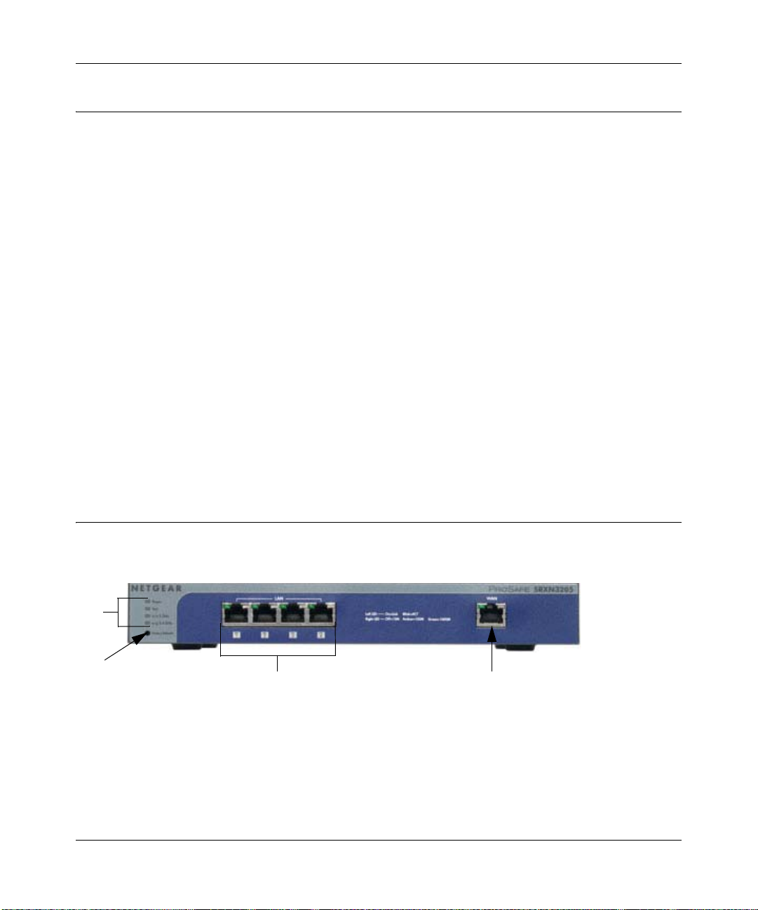
Front Panel Features
The SRXN3205’s front panel is shown below:
Figure 1-1
1-6 Introduction
v1.0, January 2010
Page 23

ProSafe Wireless-N VPN Firewall SRXN3205 Reference Manual
Table 1-1. Description of Front Panel Items
Item Activity Description
1
2
3
4
PWR
(Power)
TEST
n/a 5 GHz
n/g 2.4 GHz
Reset
button
(Press with
a sharp
object)
LAN Ports
WAN Port
On Green
Off
On Amber
Blinking Amber
Off
Off WLAN 802.11n/a (5GHz) mode is disabled.
Blink (Green) Wireless data traffic in 5GHz modes.
Off WLAN 802.11b/g/n (2.4 GHz) mode is disabled.
Blink (Green) Wireless data traffic in 2.4 GHz modes
Reboot Press once to reboot the unit.
Factory Defaults Hold in for 15 seconds (until the TEST light flashes). This resets
LAN connections Four Auto MDI/MDIX, Gigabit Ethernet ports.
WAN connection One Auto MDI/MDIX, Gigabit Ethernet port.
Power is supplied to the SRXN3205.
Power is not supplied to the SRXN3205.
Test mode: The system is initializing (On) or the initialization has
failed (Blinking).
Writing to Flash memory (during upgrading or resetting to defaults).
The system has booted successfully.
the unit to factory default settings, erasing all configuration settings
and restores the default password.
Left LED (status): On = Link; Blink = ACT
Right LED (speed): Off = 10M; Amber = 100M; Green = 1000M
Introduction 1-7
v1.0, January 2010
Page 24
ProSafe Wireless-N VPN Firewall SRXN3205 Reference Manual
1
2
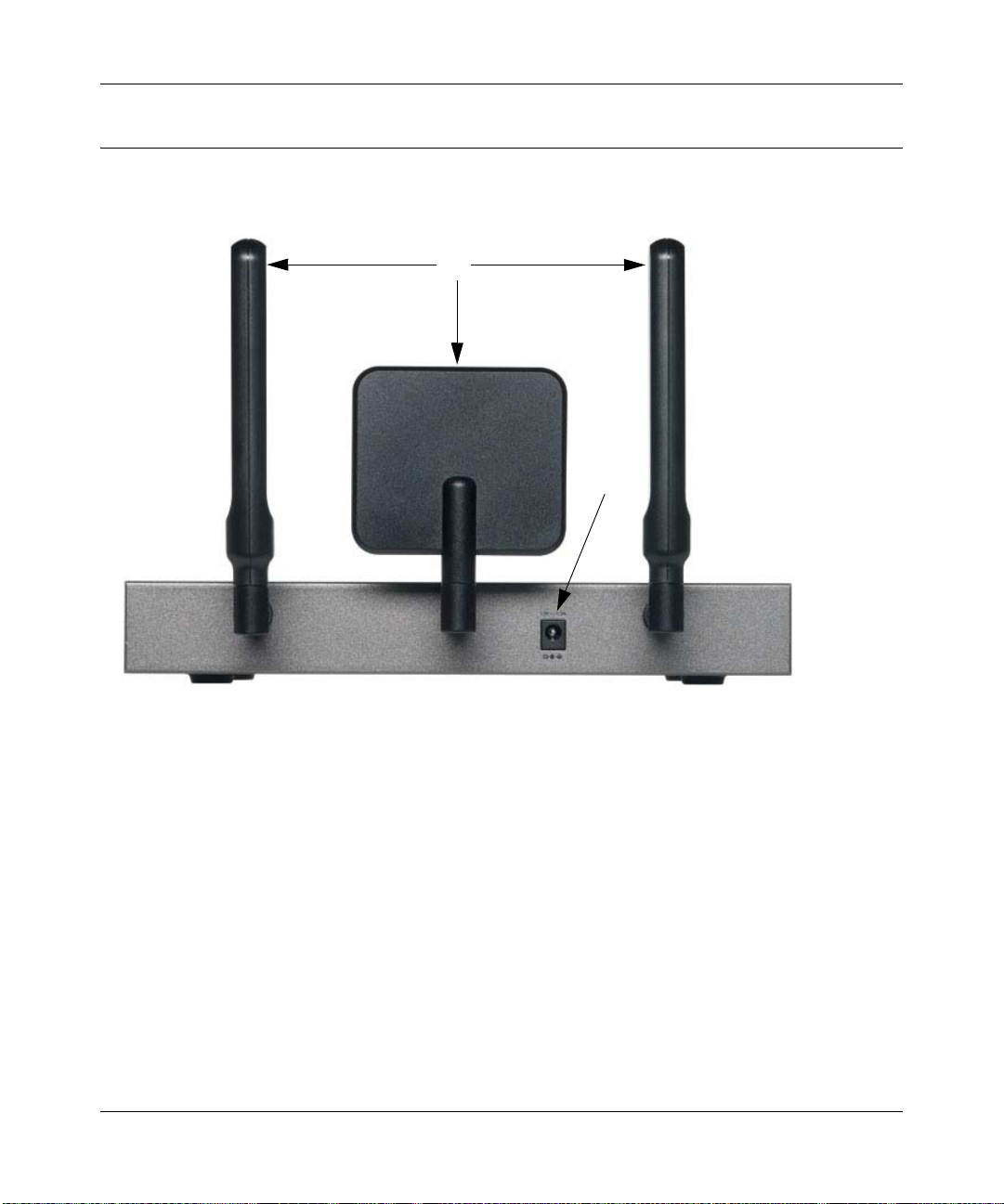
Rear Panel Features
The rear panel of the SRXN3205 is shown below.
Figure 1-2
1. Detachable (SMA) Antennas: The SRXN3205 provides three SMA connectors for the
detachable antennas (two dipole and one patch). For the best performance, attach the patch
antenna to the middle connector and attach the dipole antennas to the two connectors on both
corners. The three antennas can be positioned horizontally or vertically for the best coverage.
2. DC Power Jack: This jack connects to the SRXN3205 12V 1.5A AC-DC power adapter.
1-8 Introduction
v1.0, January 2010
Page 25
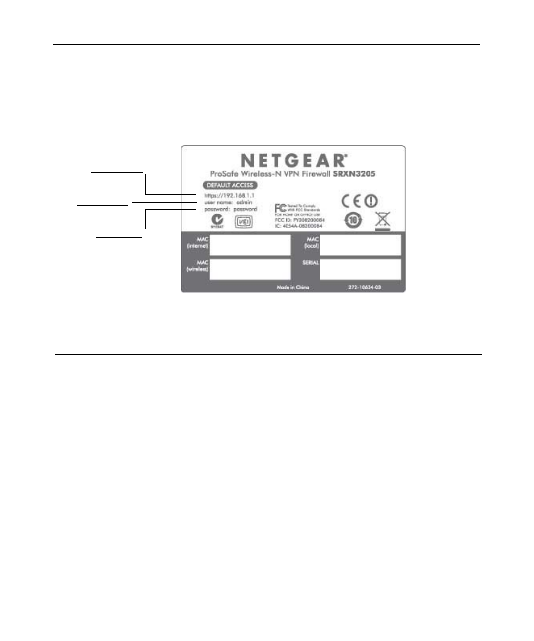
ProSafe Wireless-N VPN Firewall SRXN3205 Reference Manual
IP Address
User Name
Password
Default IP Address, Login Name, and Password Location
Check the label on the bottom of the SRXN3205’s enclosure if you need a reminder of the
following factory default information:
Figure 1-3
Qualified Web Browsers
To configure the SRXN3205, an administrator must use Internet Explorer 5.1 or higher, Apple
Safari 1.2 or higher, or Mozilla Firefox l.x Web browser with JavaScript, cookies, and SSL
enabled.
Although these web browsers are qualified for use with the SRXN3205’s Web Management
Interface for configuring the SRXN3205, SSL VPN users should choose a browser that supports
JavaScript, Java, cookies, SSL, and ActiveX to take advantage of the full suite of applications.
Note that Java is only required for the SSL VPN portal, not the Web Management Interface.
Introduction 1-9
v1.0, January 2010
Page 26

ProSafe Wireless-N VPN Firewall SRXN3205 Reference Manual
1-10 Introduction
v1.0, January 2010
Page 27

ProSafe Wireless-N VPN Firewall SRXN3205 Reference Manual
Chapter 2
Connecting to the Internet (WAN)
The initial Internet configuration of the ProSafe Wireless-N VPN Firewall SRXN3205 is described
in this chapter.
This chapter contains the following sections:
• “Understanding the Connection Steps” on this page
• “Logging into the VPN Firewall” on page 2-2
• “Navigating the Menus” on page 2-3
• “Configuring the Internet Connection (WAN)” on page 2-4
• “Configuring Dynamic DNS” on page 2-12
• “Configuring the Advanced WAN Options (Optional)” on page 2-14
Understanding the Connection Steps
Typically, six steps are required to complete the basic Internet connection of your VPN firewall.
1. Connect the firewall to your network. Connect the cables and restart your network
according to the instructions in the printed installation guide included in the product package.
A PDF of the FVX338 ProSafe VPN Fir ewall 200 Installation Guide is on the product CD and
on the NETGEAR website at http://kbserver.netgear.com.
2. Log in to the VPN firewall. After logging in, you are ready to set up and configure your VPN
firewall. You can also change your password and enable remote management at this time. See
“Logging into the VPN Firewall” on page 2-2.
3. Configure the Internet connection to your ISP. During this phase, you will connect to your
ISP. See “Configuring the Internet Connection (WAN)” on page 2-4.
4. Configure the WAN mode. Select either Network Address Translation (NAT) or Classical
Routing. See “Configuring the WAN Mode” on page 2-11.
5. Configure dynamic DNS on the WAN port (optional). Configure your fully qualified
domain name (FQDN) during this phase (if required). See “Configuring Dynamic DNS” on
page 2-12.
Connecting to the Internet (WAN) 2-1
v1.0, January 2010
Page 28
ProSafe Wireless-N VPN Firewall SRXN3205 Reference Manual
6. Configure the WAN options (optional). Optionally, you can enable each WAN port to
respond to a ping, and you can change the factory default MTU size and port speed. However ,
these are advanced features and changing them is not usually required. See “Configuring the
Advanced WAN Options (Optional)” on page 2-14.
Each of these tasks is detailed separately in this chapter. The configuration of wireless, firewall,
and VPN features are described in later chapters.
Logging into the VPN Firewall
To connect to the VPN firewall, your computer needs to be configured to get an IP address
automatically from the VPN firewall by DHCP. For instructions on how to configure your
computer for DHCP, see the “Preparing Your Network” document that you can access from
Appendix C, “Related Documents.”
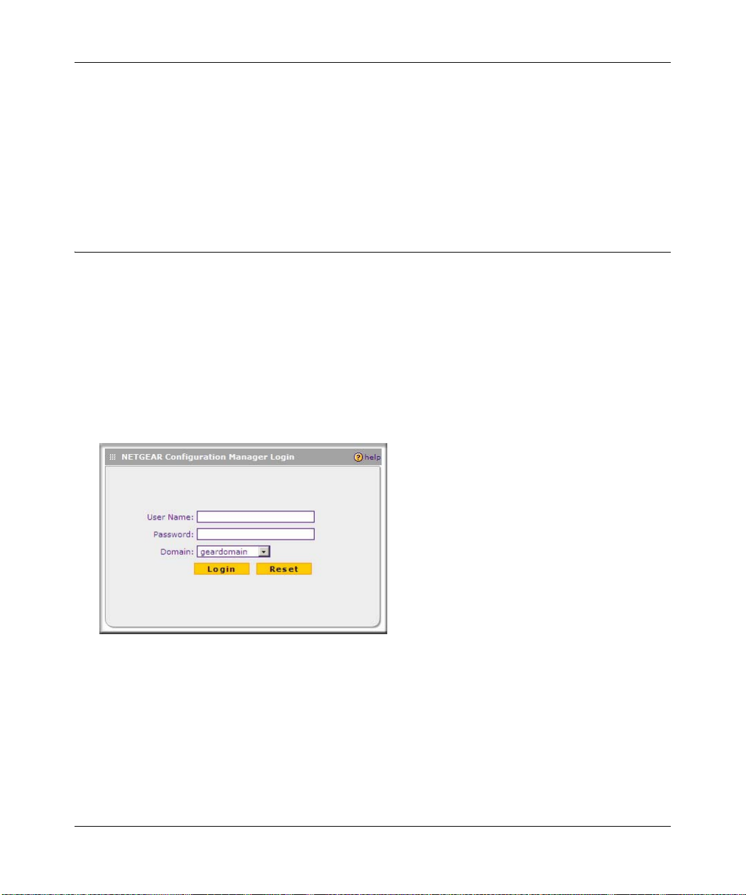
To log in to the VPN firewall, follow these steps:
1. Open a browser, and enter https://192.168.1.1 in the address field.
The login window displays in the browser.
Figure 2-1
2. Enter admin in lower case for the User Name and password for the Password.
3. Click Login. The W eb Configuration Manager appears, displaying the Router S tatus screen as
the default screen (see Figure 2-2 on page 2-3).
2-2 Connecting to the Internet (WAN)
v1.0, January 2010
Page 29
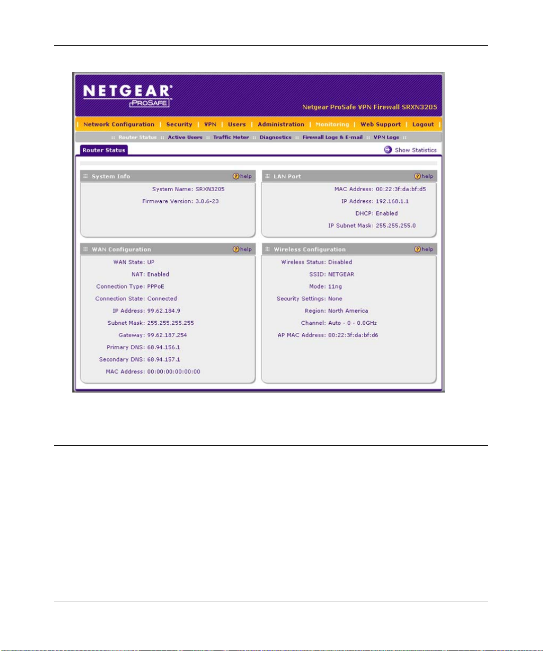
ProSafe Wireless-N VPN Firewall SRXN3205 Reference Manual
Figure 2-2
Navigating the Menus
The Web Configuration Manager menus are organized in a layered structure of main categories
and submenus:
• Main menu. The horizontal orange bar near the top of the screen is the main menu, containing
the primary configuration categories. Clicking on a primary category changes the contents of
the submenu bar.
• Submenu. The horizontal grey bar immediately below the main menu is the submenu,
containing subcategories of the currently selected primary category.
Connecting to the Internet (WAN) 2-3
v1.0, January 2010
Page 30
ProSafe Wireless-N VPN Firewall SRXN3205 Reference Manual
• Tab. Immediately below the submenu bar, at the top of the menu active window, are one or
more tabs, further subdividing the currently selected subcategory if necessary.
• Option arrow . To the right of the tabs on some menus are one or more blue dots with an arrow
in the center . Clicking an option arrow brings up either a popup window or an ad vanced option
menu.
Tip: In the instructions in this guide, we may refer to a menu using the notation
primary > subcategory, such as Network Configuration > WAN Settings. In
this example, Network Configuration is the selected primary category (in the
main menu) and WAN Settings is the selected subcategory (in the submenu).
You can now proceed to the first configuration task, configuring the VPN firewall’s Internet
connections.
Configuring the Internet Connection (WAN)
To set up your VPN firewall for secure Internet connections, you configure the WAN port. The
Web Configuration Manager offers two connectio n configuration options:
• Automatic detection and configuration of the network connection.
• Manual configuration of the network connection.
Each option is detailed in the following sections.
Automatically Detecting and Connecting
To automatically configure the WAN port for connection to the Internet:
1. Select Network Configuration > WAN Settings from the menu/submenu.
The WAN tabs appear on screen with the WAN ISP Settings screen in view (see Figure 2-3 on
page 2-5).
2-4 Connecting to the Internet (WAN)
v1.0, January 2010
Page 31

ProSafe Wireless-N VPN Firewall SRXN3205 Reference Manual
Figure 2-3
2. Click Auto Detect at the bottom of the screen.
Connecting to the Internet (WAN) 2-5
v1.0, January 2010
Page 32

ProSafe Wireless-N VPN Firewall SRXN3205 Reference Manual
Auto Detect will probe the WAN port for a range of connection methods and suggest one that
your ISP appears to support.
a. If Auto Detect is successful, a status bar at the top of the screen will display the results:.
Figure 2-4
b. If Auto Detect senses a connection method that requires input from yo u, it will prompt you
for the information. All methods with the required settings are detailed in the following
table.
Table 2-1. Internet connection methods
Connection Method Data Required
DHCP (Dynamic IP) No data is required.
PPPoE Login (Username, Password);
Account Name, Domain Name (sometimes required).
PPTP Login (Username, Password),
Local IP address, and PPTP Server IP address;
Account Name (sometimes required).
Fixed (Static) IP Static IP address, Subnet, and Gateway IP; DNS Server IP addresses.
c. If Auto Detect does not find a connection, you will be prompted to (1) check the physical
connection between your VPN firewall and the cable or DSL line, or to (2) check your
VPN firewall’s MAC address (For more information, see “Troubleshooting the ISP
Connection” on page 11-4).
3. To verify the connection, click the WAN Status option arrow at the top right of the screen.
A popup window appears, displaying the connection status of the WAN port (see Figure 2-5
on page 2-7).
2-6 Connecting to the Internet (WAN)
v1.0, January 2010
Page 33

ProSafe Wireless-N VPN Firewall SRXN3205 Reference Manual
Figure 2-5
The WAN Status window should show a valid IP address and gateway. If the configuration
was not successful, go to “Manually Configuring the Internet Connection” following this
section, or see “Troubleshooting the ISP Connection” on page 11-4.
Note: If the configuration process was successful, you are connected to the Internet
through the WAN port.
4. Click Test to evaluate your entries.
The VPN firewall will attempt to connect to the NETGEAR website. If a successful
connection is made, NETGEAR’s website appears.
If the automatic WAN ISP configurations failed, you can attempt a manual configuration as
described in the following section, or see “Troubleshooting the ISP Connection” on page 11-4.
Manually Configuring the Internet Connection
Unless your ISP automatically assigns your configuration automatically via DHCP, you will need
to obtain configuration parameters from your ISP in order to manually establish an Internet
connection. The necessary parameters for various connection types are listed in Table 2-1 on
page 2-6.
Connecting to the Internet (WAN) 2-7
v1.0, January 2010
Page 34

ProSafe Wireless-N VPN Firewall SRXN3205 Reference Manual
To manually configure your WAN ISP Settings:
1. Select Network Configuration > WAN ISP Settings. The WAN ISP Settings screen is
displayed (see Figure 2-3 on page 2-5 for the entire screen).
2. In the ISP Login section, choose one of these options:
• If your ISP requires an initial login to establish an Internet connection, click Yes (this is
the default).
• If a login is not required, click No and ignore the Login and Password fields.
Figure 2-6
3. If you clicked Yes, enter the ISP-provided Login and Password information.
4. In the ISP Type section, select the type of ISP connection you use from the two listed options.
(By default, “Other (PPPoE)” is selected.)
Figure 2-7
• Other (PPPoE). If you have installed login software such as WinPoET or Ethernet, then
your connection type is PPPoE. Configure the following fields:
– Account Name. Valid account name for the PPPoE connection.
– Domain Name. Name of your ISP’s domain or your domain name if your ISP has
assigned one. In most cases, you may leave this field blank.
2-8 Connecting to the Internet (WAN)
v1.0, January 2010
Page 35
ProSafe Wireless-N VPN Firewall SRXN3205 Reference Manual
– Idle Timeout. Select Keep Connected , to keep the connection always on. To logout
after the connection is idle for a period of time, click Idle Time and in the timeout
field enter the number of minutes to wait before disconnecting.
– Connection Reset. Select this checkbox to to specify a time when the PPPoE WAN
connection is reset, that is, the connection is disconnected momentarily and then reestablished. Enter the hour and minutes in the Disconnect Time fields to specify when
the connection should be disconnected. Enter the seconds in the Delay field to specify
the period after which the connection should be re-established.
• PPTP. Select this option if your ISP is Austria Telecom or any other ISP that uses PPTP as
a login protocol. Configure the following fields:
– Account Name. (Also known as Host Name or System Name.) Enter the valid
account name for the PPTP connection (usually your e-mail name as assigned by your
ISP). Some ISPs require entering your full e-mail address here.
– Domain Name. Your domain name or workgroup name assigned by your ISP, or your
ISPs domain name. You may leave this field blank.
– Idle Timeout. Check the Keep Connected radio box to keep the connection always
on. To logout after the connection is idle for a period of time, click Idle Time and
enter the number of minutes to wait before disconnecting in the timeout field. This is
useful if your ISP charges you based on the amount of time you have logged in.
– My IP Address. IP address assigned by the ISP to make the connection with the ISP
server.
– Server IP Address. IP address of the PPTP server.
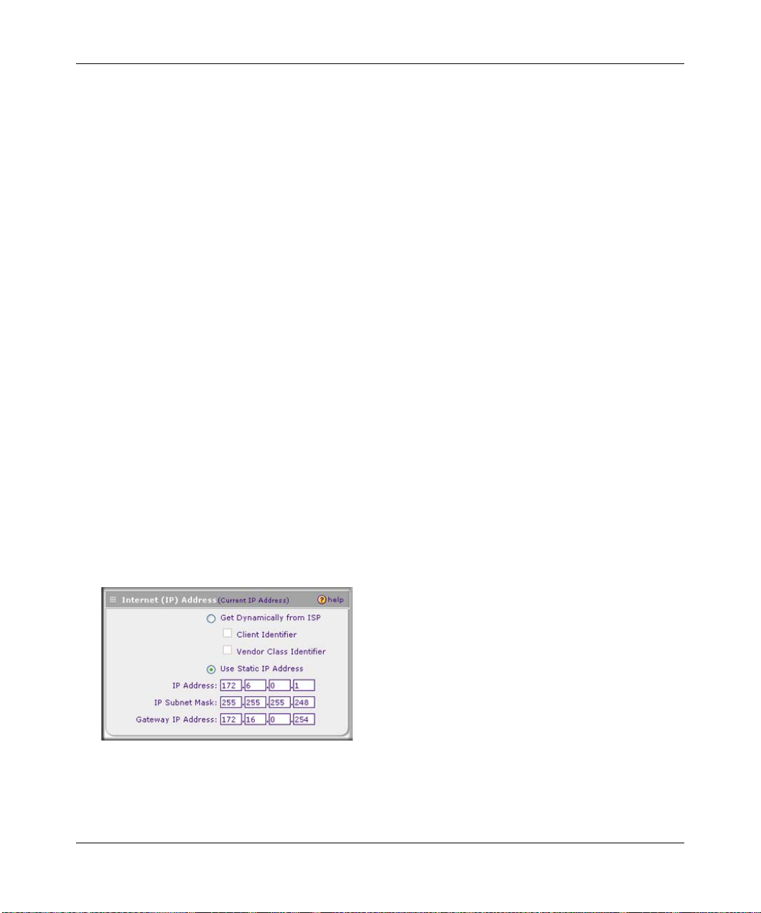
5. Review the Internet (IP) Address options.
Figure 2-8
Connecting to the Internet (WAN) 2-9
v1.0, January 2010
Page 36

ProSafe Wireless-N VPN Firewall SRXN3205 Reference Manual
• Get Dynamically from ISP. If your ISP has not assigned a static IP address, select this
radio button. The ISP will automatically assign an IP address to the VPN firewall using
DHCP network protocol. The IP address and subnet mask fields will be inactivated. As an
option, you can select the following checkboxes:
– Client Identifier. Select this checkbox if your ISP requires the Client Identifier
information to assign an IP address using DHCP.
– Vendor Class Identifier. Select this checkbox if your ISP requires the Vendor Class
Identifier information to assign an IP address using DHCP.
• Use Static IP Address. If your ISP has assigned a fixed (static) IP address, select this
radio button, and configure the following fields:
– IP Address. Enter the Static IP address assigned to you, that identifies the VPN
firewall to your ISP.
– Subnet Mask. Enter the mask provided by the ISP or your network administrator.
– Gateway IP Address. Enter the IP address of the ISP’s gateway, provided by the ISP
or your network administrator.
6. Review the Domain Name Server (DNS) server options.
Figure 2-9
• If your ISP has not assigned any Domain Name Servers (DNS) addresses, click Get
Dynamically from ISP.
• If your ISP (or your IT department) has assigned DNS addresses, click Use These DNS
Servers and enter the DNS server IP addresses provided to you in the fields.
7. Click Apply to save any changes to the WAN ISP Settings. (Or click Reset to discard any
changes and revert to the previous settings.)
8. Click Test to evaluate your entries.
The VPN firewall will attempt to connect to the NETGEAR website. If a successful
connection is made, NETGEAR’s website appears.
2-10 Connecting to the Internet (WAN)
v1.0, January 2010
Page 37
ProSafe Wireless-N VPN Firewall SRXN3205 Reference Manual
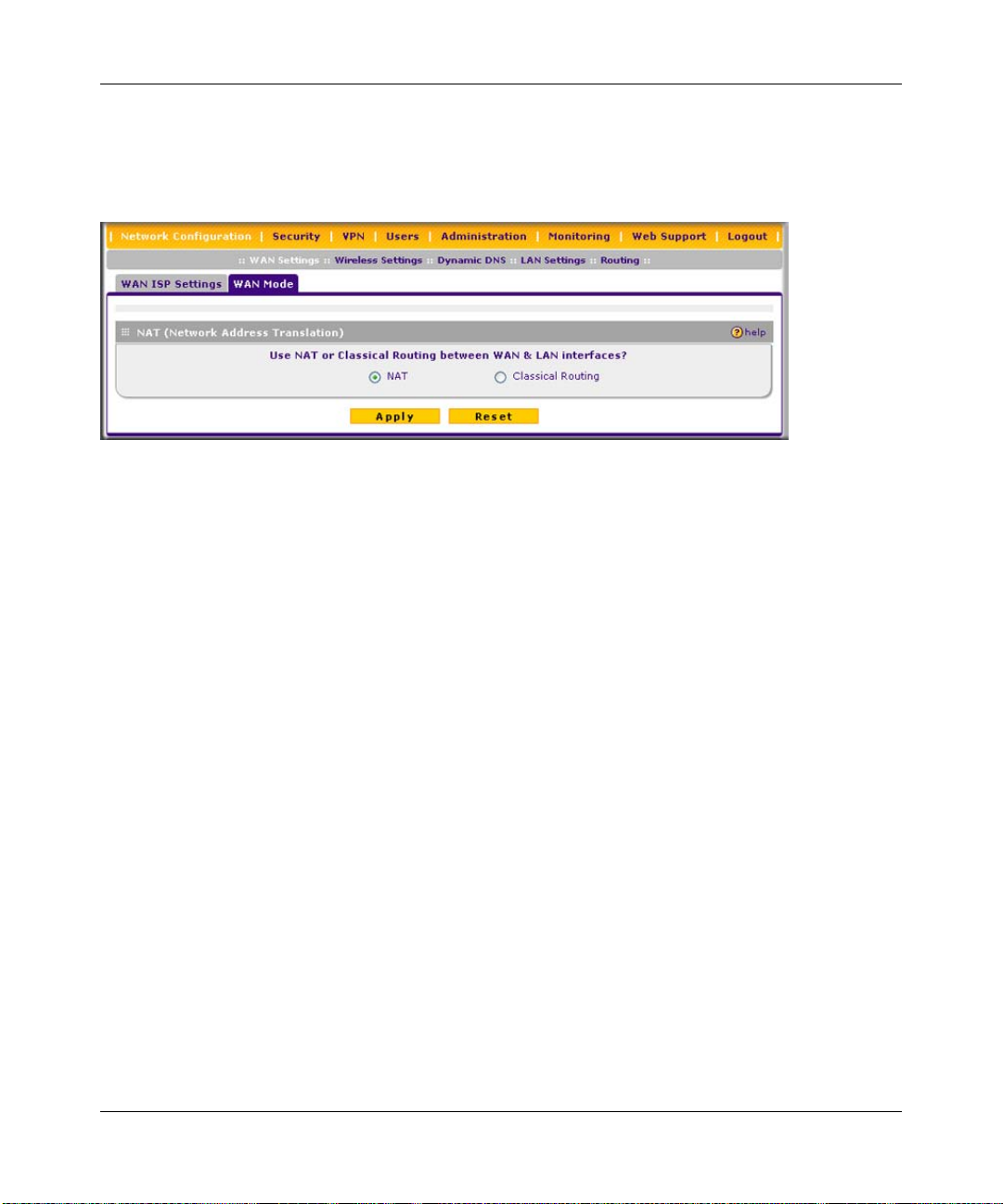
Configuring the WAN Mode
T o access the WAN Mode, click on Network Configuration > W AN Settings and select the WAN
Mode tab. The WAN Mode screen displays.
Figure 2-10
The WAN Mode screen allows you to configure how your firewall uses the external Internet
connection. This screen gives you two choices for accessing the external Internet connection.
• Network Address Translation (NAT). This technique allows several computers on a LAN to
share the same Internet connection (IP address) while using private IP address on the LAN,
which are hidden from the Internet.
• Classical Routing. This method allows the firewall to perform the routing, but requires
separate valid static Internet IP address for each PC on your LAN.
Network Address Translation
Network Address Translation (NAT) allows all PCs on your LAN to share a single public Internet
IP address. From the Internet, there is only a single device (the VPN firewall) and a single IP
address. PCs on your LAN can use any private IP address range, and these IP addresses are not
visible from the Internet.
• The VPN firewall uses NAT to select the correct PC (on your LAN) to receive any incoming
data.
• If you only have a single public Internet IP address, you MUST use NAT. (the default setting).
• If your ISP has provided you with multiple public IP addresses, you can use one address as the
primary shared address for Internet access by your PCs, and you can map incoming traffic on
the other public IP addresses to specific PCs on your LAN. This one-to-one inbound mapping
is configured using an inbound firewall rule.
Connecting to the Internet (WAN) 2-11
v1.0, January 2010
Page 38

ProSafe Wireless-N VPN Firewall SRXN3205 Reference Manual
Classical Routing
In classical routing mode, the VPN firewall performs routing, but without NAT. To gain Internet
access, each PC on your LAN must have a valid static Internet IP address.
If your ISP has allocated a number of static IP addresses to you, and you have assigned one of
these addresses to each PC, you can choose classical routing. Or, you can use classical routing for
routing private IP addresses within a campus environment.
To learn the status of the WAN port, you can view the Router Status screen (see “Monitoring the
VPN Tunnel Connection S tatus” on page 10-15) or look at the LEDs on the front panel (see “Front
Panel Features” on page 1-6).
Configuring Dynamic DNS
Note: Dynamic DNS enables you to employ some VPN configurations that require using
an FQDN instead of the WAN IP address.
Dynamic DNS (DDNS) is an Internet service that allows routers with varying public IP addresses
to be located using Internet domain names. To use DDNS, you must setup an account with a
DDNS provider such as DynDNS.org, TZO.com, Oray.net, or 3322.org. Links to DynDNS, TZO,
Oray, and 3322 are provided for your convenience on the Dynamic DNS Configuration screen.
The VPN firewall firmware includes software that notifies dynamic DNS servers of changes in the
WAN IP address, so that the services running on this network can be accessed by others on the
Internet.
If your network has a permanently assigned IP address, you can register a domain name and ha ve
that name linked with your IP address by public Domain Name Servers (DNS). However, if your
Internet account uses a dynamically assigned IP address, you will not know in advance what your
IP address will be, and the address can change frequently—hence, the need for a commercial
DDNS service, which allows you to register an extension to its domain, and restores DNS requests
for the resulting FQDN to your frequently-changing IP address.
After you have configured your account information in the firewall, whenever your ISP-assigned
IP address changes, your firewall will automatically contact your DDNS service provider, log in to
your account, and register your new IP address.
• For auto-rollover mode, you will need a fully qualified domain name (FQDN) to implement
features such as exposed hosts and virtual private networks regardless of whether you have a
fixed or dynamic IP address.
2-12 Connecting to the Internet (WAN)
v1.0, January 2010
Page 39
ProSafe Wireless-N VPN Firewall SRXN3205 Reference Manual
• For load balancing mode, you may still need a fully qualified domain name (FQDN) either for
convenience or if you have a dynamic IP address.
Note: If your ISP assigns a private WAN IP address such as 192.168.x.x or 10.x.x.x, the
dynamic DNS service will not work because private addresses will not be routed
on the Internet.
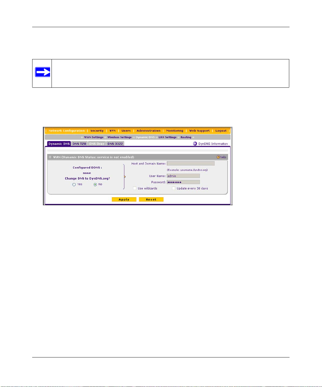
To configure dynamic DNS:
1. Select Network Configuration > Dynamic DNS from the main/submenu. The Dynamic DNS
screen is displayed.
Figure 2-11
2. Select the dynamic DNS service that you will use.
The fields corresponding to the selection you have chosen will be activated. Each DDNS
service provider requires its own parameters.
3. Access the website of one of the DDNS service providers and set up an account. Links to three
DDNS providers are in the tab header.
4. After registering for your account, return to the Dynamic DNS screen and enter the required
fields for the DDNS service you selected:
a. In the Host and Domain Name field, enter the entire FQDN name that your dynamic DNS
service provider gave you (for example: <yourname>.dyndns.org).
b. Enter the user name, user e-mail Address, or account name requested by the DDNS
Service to identify you when logging into your DDNS account.
c. Enter the password, or user key, for your DDNS account.
Connecting to the Internet (WAN) 2-13
v1.0, January 2010
Page 40

ProSafe Wireless-N VPN Firewall SRXN3205 Reference Manual
d. If your dynamic DNS provider allows the use of wildcards in resolving your URL, check
Use wildcards to activate this feature.
For example, the wildcard feature will cause anything.yourhost.dyndns.org to be aliased
to the same IP address as yourhost.dyndns.org
e. If your dynamic DNS provider requires you to renew your account monthly, check
Update every 30 days to have the VPN firewall renew the account automatically.
5. Click Apply to save your configuration.
Configuring the Advanced WAN Options (Optional)
To configure the Advanced WAN options:
1. Select Network Configuration > WAN Settings from the main/submenu. The WAN ISP
Settings screen displays.
2. Click the Advanced link to the right of the tabs. The WAN Advanced Options screen is
displayed.
Figure 2-12
3. Edit the default information you want to change.
a. MTU Size. The normal MTU (Maximum Transmit Unit) value for most Ethernet
networks is 1500 Bytes, or 1492 Bytes for PPPoE connections. For some ISPs, you may
need to reduce the MTU. This is rarely required, and should not be done unless you are
sure it is necessary for your ISP connection.
2-14 Connecting to the Internet (WAN)
v1.0, January 2010
Page 41

ProSafe Wireless-N VPN Firewall SRXN3205 Reference Manual
b. Port Speed. In most cases, your VPN firewall can automatically determine the connection
speed of the WAN port. If you cannot establish an Internet connection and the WAN Link
or Speed LED blinks continuously, you may need to manually select the port speed.
AutoSense is the default.
If you know the Ethernet port speed that your broadband modem supports, select it;
otherwise, select 10M. Use the half-duplex settings unless you are sure your broadband
modem supports full duplex.
c. Router’s MAC Address. Each computer or router on your network has a unique 32-bit
local Ethernet address. This is also referred to as the computer’s MAC (Media Access
Control) address. The default is Use Default Address. However, if your ISP requires
MAC authentication, then select either of these options:
• Select the Use this computer’s MAC radio button to enable the VPN firewall to use
the MAC address of the computer you are now using, or
• Select the Use this MAC Address radio button to manually type in the MAC address
that your ISP expects.
The format for the MAC address is 01:23:45:67:89:AB (numbers 0-9 and either uppercase
or lowercase letters A-F). If you select Use this MAC Address and then type in a MAC
address, your entry will be overwritten.
4. Click Apply to save your changes.
Additional WAN Related Configuration
• If you want the ability to manage the VPN firewall remotely, enable remote management at
this time (see “Enabling Remote Management Access” on page 9-9). If you enable remote
management, we strongly recommend that you change your password (see “Changing
Passwords and Administrator Settings” on page 9-8).
• At this point, you can set up the traffic meter for the WAN, if desired. See “Enabling the
Traffic Meter” on page 10-5.
Connecting to the Internet (WAN) 2-15
v1.0, January 2010
Page 42

ProSafe Wireless-N VPN Firewall SRXN3205 Reference Manual
2-16 Connecting to the Internet (WAN)
v1.0, January 2010
Page 43

ProSafe Wireless-N VPN Firewall SRXN3205 Reference Manual
Chapter 3
LAN Configuration
This chapter describes how to configure the advanced LAN features of your ProSafe Wireless-N
VPN Firewall SRXN3205.
This chapter contains the following sections:
• “Using the VPN Firewall as a DHCP Server” on this page
• “Configuring the LAN Setup Options” on page 3-2”
• “Managing Groups and Hosts (LAN Groups)” on page 3-5
• “Configuring Multi Home LAN IP Addresses” on page 3-10
• “Configuring Static Routes” on page 3-11
• “Configuring Routing Information Protocol (RIP)” on page 3-13
Using the VPN Firewall as a DHCP Server
By default, the VPN firewall will function as a DHCP (Dynamic Host Configuration Protocol)
server, allowing it to assign IP, DNS server, WINS Server, and default gateway addresses to all
computers connected to the LAN. The assigned default gateway address is the LAN address of the
VPN firewall. IP addresses will be assigned to the attached PCs from a pool of addresses that you
must specify. Each pool address is tested before it is assigned to avoid duplicate addresses on the
LAN.
For most applications, the default DHCP and TCP/IP settings of the firewall are satisfactory. See
the link to “TCP/IP Networking Basics” in Appendix C, “Related Documents” for an explanation
of DHCP and information about how to assign IP addresses for your network.
If another device on your network will be the DHCP server, or if you will manually configure the
network settings of all of your computers, clear the Enable DHCP server radio box by selecting
the Disable DHCP Server radio box. Otherwise, leave it checked.
LAN Configuration 3-1
v1.0, January 2010
Page 44

ProSafe Wireless-N VPN Firewall SRXN3205 Reference Manual
Specify the pool of IP addresses to be assigned by setting the starting IP address and ending IP
address. These addresses should be part of the same IP address subnet as the VPN firewall’s LAN
IP address. Using the default addressing scheme, you would define a range between 192.168.1.2
and 192.168.1.100, although you may wish to save part of the range for devices with fixed
addresses.
The VPN firewall will deliver the following settings to any LAN device that requests DHCP:
• An IP address from the range you have defined.
• Subnet mask.
• Gateway IP address (the VPN firewall’s LAN IP address).
• Primary DNS server (the VPN firewall’s LAN IP address).
• WINS server (if you entered a WINS server address in the DHCP section of the LAN Setup
screen).
• Lease time (date obtained and duration of lease).
DHCP Relay options allow you to make the VPN firewall a DHCP relay agent. The DHCP Relay
Agent makes it possible for DHCP broadcast messages to be sent over routers that do not support
forwarding of these types of messages. The DHCP Relay Agent is therefore the routing protocol
that enables DHCP clients to obtain IP addresses from a DHCP server on a remote subnet, or
which is not located on the local subnet. If you have no configured DHCP Relay Agent, your
clients would only be able to obtain IP addresses from the DHCP server which is on the same
subnet. T o enable clients to obtain IP addresses from a DHCP server on a remote subnet, you have
to configure the DHCP Relay Agent on the subnet that contains the remote clients, so that it can
relay DHCP broadcast messages to your DHCP server.
When the DNS Proxy option is enabled, the VPN firewallwill act as a proxy for all DNS requests
and communicate with the ISP’s DNS servers (as configured in the WAN settings page). All
DHCP clients will receive the Primary/Secondary DNS IP along with the IP address where the
DNS proxy is running, that is, the VPN firewall’s LAN IP address. When disabled, all DHCP
clients will receive the DNS IP addresses of the ISP excluding the DNS proxy IP address.
Configuring the LAN Setup Options
The LAN Setup screen allows configuration of LAN IP services such as DHCP and allows you to
configure a secondary or “multi-home” LAN IP setup on the LAN. The default values are suitable
for most users and situations. These are advanced settings usually configured by a network
administrator.
3-2 LAN Configuration
v1.0, January 2010
Page 45
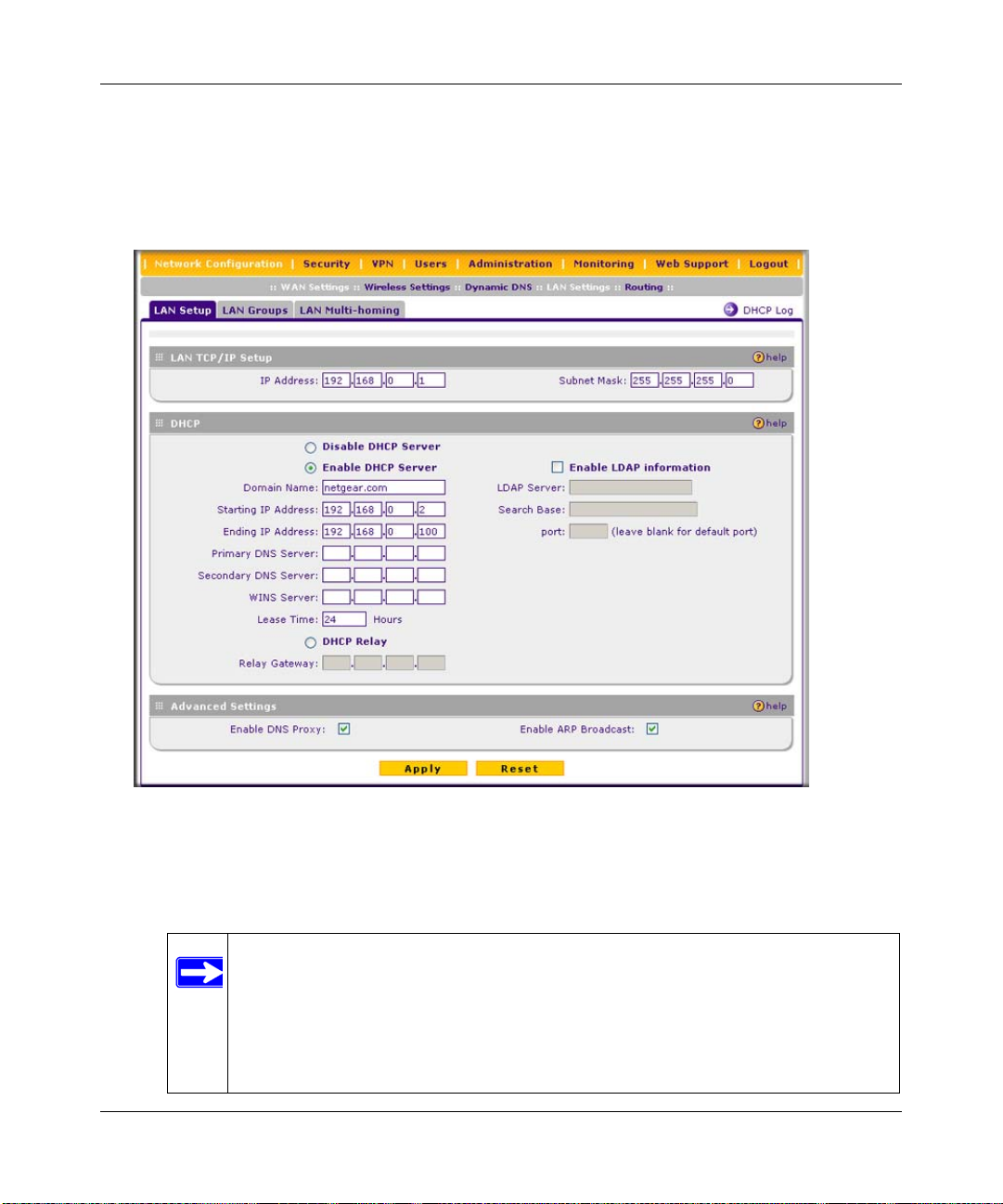
ProSafe Wireless-N VPN Firewall SRXN3205 Reference Manual
To modify your LAN setup, follow these steps:
1. Select Network Configuration > LAN Settings from the main/submenu.
The LAN Settings tabs (LAN Setup, LAN Groups, and LAN Multi-homing) are displayed
with the LAN Setup screen in view..
Figure 3-1
2. In the LAN TCP/IP Setup section, configure the following settings:
• IP Address. The LAN address of your VPN firewall (factory default: 192.168.1.1).
Note: If you change the LAN IP address of the VPN firewall while connected
through the browser, you will be disconnected. You must then open a new
connection to the new IP address and log in again. For example, if you
change the default IP address 192.168.1.1 to 10.0.0.1, y ou must now ent er
https://10.0.0.1 in your browser to reconnect to the Web Configuration
Manager.
LAN Configuration 3-3
v1.0, January 2010
Page 46

ProSafe Wireless-N VPN Firewall SRXN3205 Reference Manual
• IP Subnet Mask. The subnet mask specifies the network number portion of an IP address.
Your VPN firewall will automatically calculate the subnet mask based on the IP address
that you assign. Unless you are implementing subnetting, use 255.255.255.0 as the subnet
mask.
3. In the DHCP section, select Disable DHCP Server, Enable DHCP Server, or DHCP Relay.
By default, the VPN firewall will function as a DHCP server, providing TCP/IP configuration
settings for all computers connected to the VPN firewall’s LAN. If another device on your
network will be the DHCP server, or if you will manually configure all devices, click Disable
DHCP Server. If the VPN firewall will function as a DHCP relay agent, select DHCP Relay
and enter the IP address of the DHCP relay gateway in the Relay Gateway field.
If the DHCP server is enabled, enter the following settings:
• Domain Name. (Optional) The DHCP will assign the entered domain to its DHCP clients.
• Starting IP Address. Specifies the first of the contiguous addresses in the IP address pool.
Any new DHCP client joining the LAN will be assigned an IP address between this
address and the Ending IP Address. The IP address 192.168.1.2 is the default start address.
• Ending IP Address. Specifies the last of the contiguous addresses in the IP address pool.
The IP address 192.168.1.100 is the default ending address.
Note: The Starting and Ending DHCP addresses should be in the same subnet as
the LAN IP address of the VPN firewall (the IP Address configured in the
LAN TCP/IP Setup section).
• Primary DNS Server. (Optional) If an IP address is specified, the VPN firewall will
provide this address as the primary DNS server IP address. If no address is specified, the
VPN firewall will provide its own LAN IP address as the primary DNS server IP address.
• Secondary DNS Server. (Optional) If an IP address is specified, the VPN firewall will
provide this address as the secondary DNS server IP address.
• WINS Server. (Optional) Specifies the IP address of a local Windows NetBios Server if
one is present in your network.
• Lease Time. Specifies the duration for which a DHCP-provided IP address will be leased
to a client.
• Enable DNS Proxy . When DNS proxy is enabled (default), the DHCP server will provide
the VPN firewall LAN IP address as the DNS server for address name resolution. If this
box is unchecked, the DHCP server will provide the ISP’s DNS server IP addresses. The
VPN firewall will still service DNS requests sent to its LAN IP address unless you disable
DNS Proxy in the DHCP settings (see “Attack Checks” on page 5-14).
3-4 LAN Configuration
v1.0, January 2010
Page 47

ProSafe Wireless-N VPN Firewall SRXN3205 Reference Manual
If you will use a Lightweight Directory Access Protocol (LDAP) authentication server for
network-validated domain-based authentication, select Enable LDAP Information to enable
the DHCP server to provide LDAP server information.
Enter the following settings:
• LDAP Server. Specifies the name or the IP address of the device that hosts the LDAP
server.
• Search Base. Specifies the distinguished name (dn) at which to start the search, specified
as a sequence of relative distinguished names (rdn), connected with commas and without
any blank spaces. For most users, the search base is a variation of the domain name. For
example, if your domain is yourcompany.com, your search base dn might be as follows:
dc=yourcompany,dc=com.
• port. Specifies the port number that the LDAP server is using. Leave this field blank for
the default port.
4. In the Advanced Settings section, enter the following settings, which are optional:
• Enable DNS Proxy. If the DNS proxy is enabled (which is the default setting), the DHCP
server will provide the VPN firewall’s LAN IP address as the DNS server for address
name resolution. If this box is unchecked, the DHCP server will provide the ISP’s DNS
server IP addresses. The VPN firewall will still service DNS requests sent to its LAN IP
address unless you disable DNS Proxy in the firewall settings (see “Attack Checks” on
page 5-14).
• Enable ARP Broadcast. If ARP broadcast is enabled (which is the default setting), the
Address Resolution Protocol (ARP) is broadcasted on the LAN so that IP addresses can be
mapped to physical addresses (that is, MAC addresses).
5. Click Apply to save your settings.
Note: Once you have completed the LAN setup, all outbound traffic is allowed and
all inbound traffic is discarded. To change these default traffic rules, refer to
Chapter 5, “Firewall Security and Content Filtering.”
Managing Groups and Hosts (LAN Groups)
The Known PCs and Devices table on the LAN Groups screen contains a list of all known PCs
and network devices that are assigned dynamic IP addresses by the VPN firewall, or have been
discovered by other means. Collectively, these entries make up the LAN Groups Database.
LAN Configuration 3-5
v1.0, January 2010
Page 48

ProSafe Wireless-N VPN Firewall SRXN3205 Reference Manual
The LAN Groups Database is updated by these methods:
• DHCP Client Requests. By default, the DHCP server in this VPN firewall is enabled, and
will accept and respond to DHCP client requests from PCs and other network devices. These
requests also generate an entry in the LAN Groups Database. Because of this, leaving the
DHCP server feature (LAN Setup screen) enabled is strongly recommended.
• Scanning the Network. The local network is scanned using ARP requests. The ARP scan will
detect active devices that are not DHCP clients. However, sometimes the name of the PC or
device cannot be accurately determined, and will appear in the database as unknown.
• Manual Entry. You can manually enter information about a network device.
Some advantages of the LAN Groups Database are:
• Generally, you do not need to enter IP addresses or MAC addresses. Instead, you can just
select the desired PC or device.
• No need to reserve an IP address for a PC in the DHCP server. All IP address assignments
made by the DHCP server will be maintained until the PC or device is removed from the
database, either by expiry (inactive for a long time) or by you.
• No need to use a fixed IP on PCs. Because the address allocated by the DHCP server will
never change, you don't need to assign a fixed IP to a PC to ensure it always has the same IP
address.
• MAC level control over PCs. The LAN Groups Database uses the MAC address to identify
each PC or device. So changing a PC’s IP address does not affect any restrictions on that PC.
• Group and individual control over PCs.
– You can assign PCs to Groups and apply restrictions to each Group using the Firewall
Rules screen (see “Using Rules & Services to Block or Allow Traffic” on page 5-2).
– You can also select the Groups to be covered by the Block Sites feature (see “Blocking
Internet Sites (Content Filtering)” on page 5-25).
– If necessary, you can also create Firewall Rules to apply to a single PC (see “Enabling
Source MAC Filtering (Address Filtering)” on page 5-28). Because the MAC address is
used to identify each PC, users cannot avoid these restrictions by changing the IP address.
• A computer is identified by its MAC address—not its IP address. Hence, changing a
computer’s IP address does not affect any restrictions applied to that PC.
3-6 LAN Configuration
v1.0, January 2010
Page 49

ProSafe Wireless-N VPN Firewall SRXN3205 Reference Manual
Viewing the LAN Group s Database
To view the LAN Groups Database, follow these steps:
1. Select Network Configuration > LAN Settings from the main/submenu. The LAN Setup
screen displays (see Figure 3-1 on page 3-3).
2. Click the LAN Groups tab. The LAN Groups screen is displayed.
Figure 3-2
The Known PCs and Devices table lists the entries in the LAN Groups Database. For each
computer or device, the following fields are displayed:
• Name. The name of the PC or device. For computers that do not support the NetBIOS
protocol, this will be listed as “Unknown” (you can edit the entry manually to add a
meaningful name). If the computer was assigned an IP address by the DHCP server, then the
Name will be appended by an asterisk.
• IP Address. The current IP address of the computer. For DHCP clients of the VPN firewall,
this IP address will not change. If a computer is assigned a static IP addresses, you will need to
update this entry manually if the IP address on the computer has been changed.
• MAC Address. The MAC address of the PC’s network interface.
• Group. Each PC or device can be assigned to a single group. By default, a computer is
assigned to Group 1, unless a different group is chosen from the Group pull-down menu.
LAN Configuration 3-7
v1.0, January 2010
Page 50

ProSafe Wireless-N VPN Firewall SRXN3205 Reference Manual
• Action. Allows modification of the selected entry by clicking edit.
Note: If the VPN firewall is rebooted, the table data is lost until the VPN firewall
rediscovers the devices.
Adding Devices to the LAN Groups Database
To add devices manually to the LAN Groups Database, follow these steps:
1. In the Add Known PCs and Devices section, make the following entries:
• Name. Enter the name of the PC or device.
• IP Address Type. From the pull-down menu, choose how this device receives its IP
address. The choices are:
– Fixed (Set on PC). The IP address is statically assigned on the computer.
– Reserved (DHCP Client). Directs the VPN firewall’s DHCP server to always assign
the specified IP address to this client during the DHCP negotiation.
Note: When assigning a Reserved IP address to a client, the IP address selected
must be outside the range of addresses allocated to the DHCP server pool.
• IP Address. Enter the IP address that this computer or device is assigned in the IP
Address field. If the IP Address Type is Reserved (DHCP Client), the VPN firewall will
reserve the IP address for the associated MAC address.
• MAC Address. Enter the MAC address of the computer’s network interface in the MAC
Address field. The MAC address format is six colon-separated pairs of hexadecimal
characters (0-9 and A-F), such as 01:23:45:67:89:AB.
• Group. From the pull-down menu, select the LAN Group to which the computer will be
assigned. (Group 1 is the default group.)
2. Click Add. The device will be added to the Known PCs and Devices table.
3. As an optional step: To enable DHCP address reservation for the entry that you just added to
the Known PCs and Devices table, select the checkbox for the table entry and click Save
Binding to bind the IP address to the MAC address for DHCP assignment.
3-8 LAN Configuration
v1.0, January 2010
Page 51

ProSafe Wireless-N VPN Firewall SRXN3205 Reference Manual
Changing Group Names in the LAN Groups Database
By default, the LAN Groups are named Group1 through Group8. You can rename these group
names to be more descriptive, such as Engineering or Marketing.
To edit the names of any of the eight available groups:
1. From the LAN Groups tab, click the Edit Group Names link to the right of the tabs. The
Network Database Group Names screen appears.
Figure 3-3
2. Select the radio button next to any group name to make that name active for editing.
3. Type a new name in the field.
4. Click Apply to save your setting, each time you change a name in the field.
5. Select and edit other group names if desired.
6. Click Apply to save each field change.
Configuring DHCP Address Reservation
A computer (or device) will always receive the same IP address, if you specify a reserved IP
address for the computer (or device) on the LAN (based on the MAC address of the device), each
time it accesses the VPN firewall’s DHCP server. Reserved IP addresses should be assigned to
servers or access points that require permanent IP address settings. The reserved IP address that
you select must be outside of the DHCP Server pool.
To reserve an IP address, manually enter the device in the LAN Groups screen, specifying
Reserved (DHCP Client), as described in “Adding Devices to the LAN Groups Database” on
page 3-8.
LAN Configuration 3-9
v1.0, January 2010
Page 52
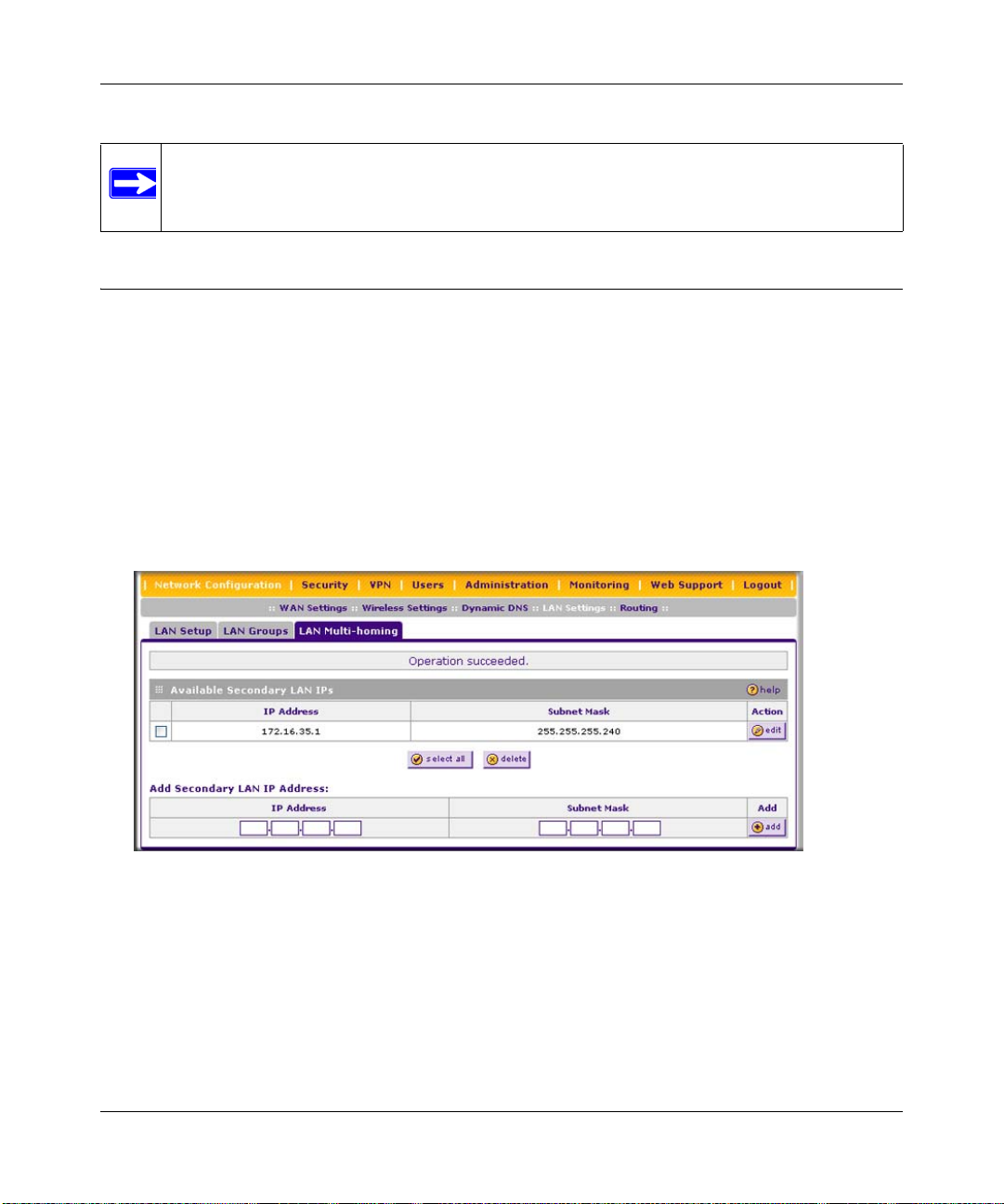
ProSafe Wireless-N VPN Firewall SRXN3205 Reference Manual
Note: The reserved address will not be assigned until the next time the PC contacts the
VPN firewall’s DHCP server. Reboot the PC or access its IP configuration and
force a DHCP release and renew.
Configuring Multi Home LAN IP Addresses
If you have computers on your LAN using different IP address ranges (for example, 172.16.2.0 or
10.0.0.0), you can add “aliases” to the LAN port, giving computers on those networks access to the
Internet through the VPN firewall. This allows the VPN firewall to act as a gateway to additional
logical subnets on your LAN. You can assign the VPN firewall an IP address on each additional
logical subnet.
To add a secondary LAN IP address, follow these steps:
1. Select Network Configuration > LAN Settings from the main/submenu.
2. Click the LAN Multi-homing tab and the LAN Multi-homing screen displays.
Figure 3-4
The Available Secondary LAN IPs table lists the secondary LAN IP addresses added to the
VPN firewall.
• IP Address. The “alias,” an additional IP address hosted by the LAN port of the VPN
firewall. This address will be the gateway for computers on the secondary subnet.
• Subnet Mask. The IPv4 subnet mask that defines the range of the secondary subnet.
3-10 LAN Configuration
v1.0, January 2010
Page 53

ProSafe Wireless-N VPN Firewall SRXN3205 Reference Manual
3. In the Add Secondary LAN IP Address section, enter the additional IP address and subnet
mask to be assigned to the LAN port of the VPN firewall.
4. Click Add. The new Secondary LAN IP address will appear in the A vailable S econdary LAN
IPs table.
Note: IP addresses on these secondary subnets cannot be configured in the DHCP
server. The hosts on the secondary subnets must be manually configured with
IP addresses, gateway IP addresses, and DNS server IP addresses.
Tip: The secondary LAN IP address will be assigned to the LAN interface of the
VPN firewall and can be used as a gateway by computers on the secondary
subnet.
Configuring Static Routes
Static Routes provide additional routing information to your VPN firewall. Under normal
circumstances, the VPN firewall has adequate routing information after it has been configured for
Internet access, and you do not need to configure additional static routes. You should configure
static routes only for unusual cases such as multiple firewalls or multiple IP subnets located on
your network.
To add or edit a static route:
1. Select Network Configuration > Routing from the main/submenu. The Routing screen is
displayed.
Figure 3-5
LAN Configuration 3-11
v1.0, January 2010
Page 54

ProSafe Wireless-N VPN Firewall SRXN3205 Reference Manual
2. Click add. The Add Static Route screen is displayed.
Figure 3-6
3. Enter a route name for this static route in the Route Name field (for identification and
management).
4. Select Active to make this route effective.
5. Select Private if you want to limit access to the LAN only.
The static route will not be advertised in RIP.
6. Enter the Destination IP Address to the host or network where the route leads.
7. Enter the IP Subnet Mask for this destination.
If the destination is a single host, enter 255.255.255.255.
8. Enter the Interface which is the physical network interface (WAN or LAN) through which
this route is accessible.
9. Enter the Gateway IP Address through which the destination host or network can be reached.
This must be a firewall on the same LAN segment as the VPN firewall.
10. Enter the Metric priority for this route.
If multiple routes to the same destination exits, the route with the lowest metric is chosen
(value must be between 1 and 15).
11. Click Apply to save your settings.
The new static route will be added to the Static Route table.
You can edit the route’s settings by clicking edit in the Action column adjacent to the route.
3-12 LAN Configuration
v1.0, January 2010
Page 55
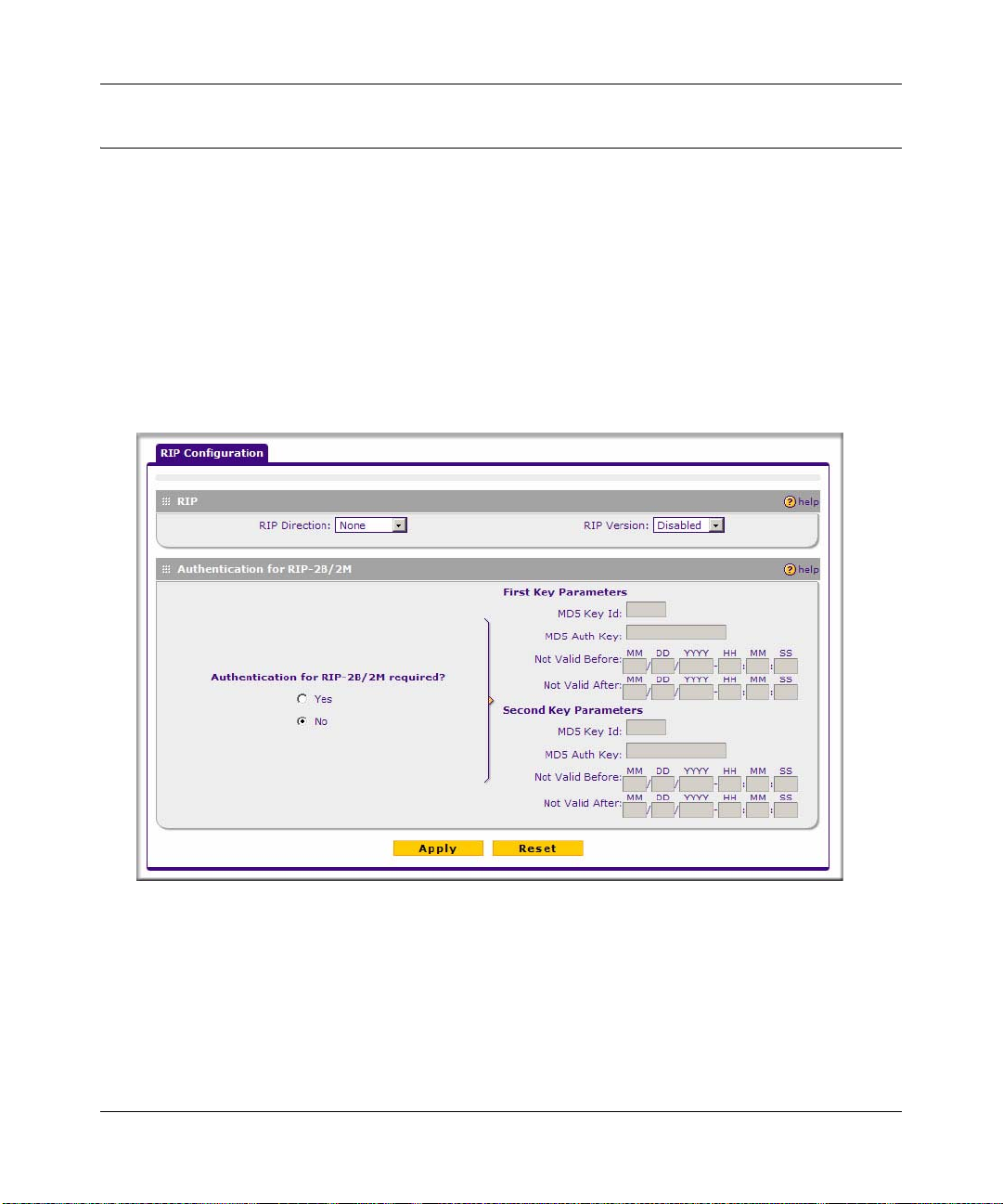
ProSafe Wireless-N VPN Firewall SRXN3205 Reference Manual
Configuring Routing Information Protocol (RIP)
RIP (Routing Information Protocol, RFC 2453) is an Interior Gateway Protocol (IGP) that is
commonly used in internal networks (LANs). It allows a router to exchange its routing information
automatically with other routers, and allows it to dynamically adjust its routing tables and adapt to
changes in the network. RIP is disabled by default.
To configure RIP:
1. Select Network Configuration > Routing from the main/submenu.
2. Click the RIP Configuration link to the right of the Routing tab. The RIP Configuration
screen is displayed.
Figure 3-7
3. From the RIP Direction pull-down menu, choose the direction in which the VPN firewall will
send and receive RIP packets. The choices are:
• None. The VPN firewall neither broadcasts its route table nor does it accept any RIP
packets from other routers. This effectively disables RIP.
LAN Configuration 3-13
v1.0, January 2010
Page 56

ProSafe Wireless-N VPN Firewall SRXN3205 Reference Manual
• In Only. The VPN firewall accepts RIP information from other routers, but does not
broadcast its routing table.
• Out Only. The VPN firewall broadcasts its routing table periodically but does not accept
RIP information from other routers.
• Both. The VPN firewall broadcasts its routing table and also processes RIP information
received from other routers.
4. From the RIP Version pull-down menu, choose the version from the following options:
• Disabled. The default section disables RIP versions.
• RIP-1. A class-based routing that does not include subnet information. This is the most
commonly supported version.
• RIP-2. This includes all the functionality of RIPv1 plus it supports subnet information.
Though the data is sent in RIP-2 format for both RIP-2B and RIP-2M, the modes in which
packets are sent are different.
– RIP-2B. Sends the routing data in RIP-2 format and uses subnet broadcasting.
– RIP-2M. Sends the routing data in RIP-2 format and uses multicasting.
5. Authentication for RIP2B/2M required? If you selected RIP-2B or RIP-2M, check the Yes
radio box to enable authentication, and enter the MD-5 keys to authenticate between devices in
the First Key Parameters and Second Key Parameters sections on the screen.
6. Click Apply to save your settings.
3-14 LAN Configuration
v1.0, January 2010
Page 57

ProSafe Wireless-N VPN Firewall SRXN3205 Reference Manual
Chapter 4
Wireless Configuration
This chapter describes how to set up your ProSafe Wireless-N VPN Firewall SRXN3205 for
wireless connectivity to your LAN. This basic configuration will enable computers with 802.11b/
g/n or 802.11a/n wireless adapters to do such things as connect to the Internet, or access printers
and files on your LAN.
Note: Indoors, computers can connect over 802.11b/g/n or 802.1 1a/g/n wireless networks
at ranges of several hundred feet or more. This distance can allow for others
outside your area to access your network. It is important to take appropriate steps
to secure your network from unauthorized access. The VPN firewall provides
highly effective security features which are covered in detail in “SSID and WEP/
WPA Settings Setup Form” on page 4-9. Deploy the security features appropriate
to your needs.
You need to prepare these four things before you can establish a connection through your wireless
VPN firewall:
• The VPN firewall connected to your LAN through the WAN port to a device such as a hub,
switch, router, or Cable/DSL gateway.
• A correctly set up ProSafe Wireless-N VPN Firewall for wireless access.
• One or more computers with properly configured 802.11b/g/n or 802.11a/n wireless adapters.
• A location for the VPN firewall that conforms to the “Wireless Equipment Placement and
Range Guidelines.
Use the following topics to set up your SRXN3205 for use as a wireless VPN firewall:
• “Wireless Equipment Placement and Range Guidelines” on page 4-2
• “Understanding the VPN Firewall Wireless Security Options” on page 4-2
• “Configuring Basic Wireless Setup (Without Security)” on page 4-4
• “Testing and Completing Wireless Setup (Without Security)” on page 4-6
• “Wireless Security Types and Settings” on page 4-8
• “Configuring Advanced Wireless Settings” on page 4 - 17
• “Restricting Wireless Access by MAC Address” on page 4-18
Wireless Configuration 4-1
v1.0, January 2010
Page 58

ProSafe Wireless-N VPN Firewall SRXN3205 Reference Manual
Wireless Equipment Placement and Range Guidelines
The operating distance or range of your wireless connection can vary significantly based on the
physical placement of the VPN firewall. The latency, data throug hput performance, and notebook
power consumption of wireless adapters also vary depending on your configuration choices.
Note: Failure to follow these guidelines can result in significant performance degradation
or inability to wirelessly connect to the VPN firewall. For complete performance
specifications, see Appendix A, “Default Settings and Technical Specifications.”
For best results, place your VPN firewall:
• Near the center of the area in which your PCs will operate.
• In an elevated location such as a high shelf where the wirelessly connected PCs have line-ofsight access (even if through walls).
• Away from sources of interference, such as PCs, microwaves, and 2.4 GHz cordless phones.
• Away from large metal surfaces.
Placing the antenna in a vertical position provides best side-to-side coverage. Placing the antenna
in a horizontal position provides best up-and-down coverage.
If you are using multiple access points for 11b/bg/ng, it is better if adjacent access points use
different radio frequency Channels to reduce interference. The recommended Channel spacing
between adjacent access points is 5 Channels (for example, use Channels 1 and 6, or 6 and 11). For
11a/na, the 6 Channel spacing is not needed.
The time it takes to establish a wireless connection can vary depending on both your security
settings and placement. Some types of security connections can take slightly longer to establish
and can consume more battery power on a notebo ok computer.
Understanding the VPN Firewall Wireless Security Options
Your wireless data transmissions can be rece ived well beyond your walls by anyone with a
compatible adapter. For this reason, use the security features of your wireless equipment. The VPN
firewall provides highly effective security features which are covered in detail in this chapter.
Deploy the security features appropriate to your needs.
4-2 Wireless Configuration
v1.0, January 2010
Page 59

ProSafe Wireless-N VPN Firewall SRXN3205 Reference Manual
Figure 4-1
There are several ways you can enhance the security of your wireless network:
• Restrict Access Based on MAC address. You can restrict access to only trusted PCs so that
unknown PCs cannot wirelessly connect to the VPN firewall. MAC address filtering adds an
obstacle against unwanted access to your network, but the data broadcast over the wireless link
is fully exposed.
• Turn Off the Broadcast of the Wireless Network Name (SSID). If you disable broadcast of
the SSID, only devices that have the correct SSID can connect. This nullifies the wireless
network “discovery” feature of some products such as Windows XP, but the data is still fully
exposed to a determined snoop using specialized test equipment like wireless sniffers.
• Use WEP. Wired Equivalent Privacy (WEP) data encryption provides data security. WEP
open authentication and WEP data encryption will block all but the most determined
eavesdropper. This data encryption mode has been superseded by WPA-PSK and WPA2-PSK
• Use WP A, WPA-PSK, WPA2, or WPA2-PSK (with or without RADIUS). Wi-Fi Protected
Access (WPA) data encryption provides data security. The very strong authentication along
with dynamic per frame rekeying of WPA make it virtually impossible to compromise. WPA
functions with TKIP (Temporal Key Integrity Protocol ) or (Advanced Encryption Standard)
encryption, WPA2 functions with AES only, and WPA+WPA2 functions with a combination
of TKIP and AES encryption.
Note: WEP and TKIP support only legacy rates of operation. So, AES is the
recommended encryption for use with 11n rates and speed.
Wireless Configuration 4-3
v1.0, January 2010
Page 60
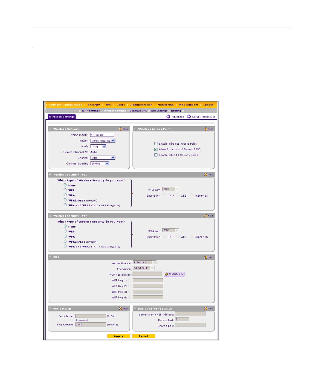
ProSafe Wireless-N VPN Firewall SRXN3205 Reference Manual
Configuring Basic Wireless Setup (Without Security)
T est wireless connectivity in your environment by setting up the unit without wireless security. To
configure the VPN firewall for basic Wireless access, follow these simple steps:
1. Select Network Configuration > Wireless Settings from the main/submenu. The Wireless
Settings screen is displayed. Use this screen to set up your wireless connectivity requirements.
Figure 4-2
4-4 Wireless Configuration
v1.0, January 2010
Page 61

ProSafe Wireless-N VPN Firewall SRXN3205 Reference Manual
2. In the Wireless Access Point section of the screen, configure the following settings:
• Enable Wireless Access Point. Select this checkbox to allow multiple devices in the
wireless network to access the WAN network and other LAN devices through the wireless
VPN firewall. This checkbox is deselected by default.
• Allow Broadcast of Name (SSID). If you want your SSID (network name) to be
broadcasted, leave this checkbox selected, which is the default setting. If you deselect this
checkbox, only devices that have the correct SSID can connect. This nullifies the wireless
network “discovery” feature of some products such as Windows XP, but the data is still
fully exposed to a determined snoop using specialized test equipment like wireless
sniffers.
• Enable 802.11d Country Code. Select this checkbox to enable the VPN firewall to
comply with the IEEE 802.11d standard (also referred to as global harmonization) in order
to satisfy regulatory wireless requirements in your country. This checkbox is deselected by
default.
3. In the Wireless Network section of the screen, configure the following settings:
• Name (SSID). Enter your network name.
• Region. From the pull-down menu, select the region where the VPN firewall will be used
(the default Region is North America).
Note: If your country or region is not listed, contact NETGEAR Support.
• Mode. Select a wireless mode from the pulldown menu or accept the default (11ng)
setting. The 802.11 selections are: a only, b only, g only , g and b, 11ng, or 11na. Select an
“only” option if all devices in the wireless network can support. Select ng mode if there
are clients in the network that support 802.11n; this mode also supports legacy 802.11b
and 802.11g clients. To support 802.11a and 802.11n clients concurrently, select na mode;
this mode will not support 802.11b or 802.11g clients.
• Leave all channel settings at the defaults.
4. In the other sections of the screen, leave all other settings at the defaults, including None as the
Wireless Security Type.
5. Click Apply at the bottom of the Wireless Settings screen.
If the settings were accepted, a message appears in the center of the screen: Operation
succeeded.
Wireless Configuration 4-5
v1.0, January 2010
Page 62

ProSafe Wireless-N VPN Firewall SRXN3205 Reference Manual
6. Prepare a PC as the wireless PC Client with a wireless Ethernet adapter insta lled. Verify that
you can wirelessly access a file or a printer on the LAN connected to the VPN firewall.
Testing and Completing Wireless Setup (Without Security)
The purpose of setting your wireless settings in stages, without the security settings, is to eliminate
any possible errors in setting up your wireless settings before adding the more complicated
security settings. This method will greatly aid you in discovering where the errors in your security
settings are by removing doubts about your wireless settings.
Testing Wireless Connectivity (Without Security)
Follow the instructions below to test wireless connectivity. Once you have established wireless
connectivity, you can enable security settings appropriate to your needs.
1. Select Network Configuration > Wireless Settings from main/submenu.
2. In the Wireless Network section of the screen, ensure that Auto is selected from the Channel
pull-down menu. (Auto is the default setting.)
The Auto setting selects a channel that has the least interference. It should not be necessary to
change the wireless channel unless you notice interference problems or are near another
wireless access point. Select a channel that is not being used by any other wireless networks
within several hundred feet of your VPN firewall.
Note: The SSID of a client computer must match what you configured in the VPN
firewall. If these do not match, you will not get a wireless connection to the
VPN firewall.
3. From the Wireless Network section of the screen, record the name used for SSID.
4. In the Wireless Access Point section of the screen, deselect the Allow Broadcast of Name
(SSID) checkbox.
Note: If you are configuring the VPN firewall from a wireless computer, you will
lose your wireless connection when you click Apply to update settings. You
will then need to update the wireless settings of your computer accordingly.
5. Click Apply to save any changes.
4-6 Wireless Configuration
v1.0, January 2010
Page 63

ProSafe Wireless-N VPN Firewall SRXN3205 Reference Manual
6. Prepare PC(s) as the wireless PC Client(s) with wireless Ethernet adapters installed.
7. Configure the Client PCs to obtain the IP and DNS addresses automatically using the internal
DHCP server (DHCP is the default firewall setting).
8. Configure the wireless adapters of your Client PCs to have the same SSID that you configured
on the VPN firewall.
9. Using this Client PCs, verify these PCs have a wireless link by trying to a ccess a file or a
printer on the LAN connected to the VPN firewall.
10. Once you have verified wireless connectivity to the VPN firewall, you can configure the
wireless channel and security functions. See the “Configuring the Wireless Channel Settings
(Without Security)” on this page and the “Wireless Security Types and Settings” on page 4-8.
Configuring the Wireless Channel Settings (Without Security)
To configure the wireless channel settings of your VPN firewall:
1. Select Network Configuration > Wireless Settings from the main/submenu. The Wireless
Settings screen is displayed (see Figure 4-1 on page 4-3).
2. In the Wireless Network section of the screen, configure the following settings:
Note: The Current Channel No shows the currently configured channel.
• Channel. The default setting is Auto. Use the default setting or select a channel and
frequency from the pull-down menu to use on your wireless LAN.
The Auto option intelligently picks a channel and frequency with least interference. The
wireless channel in use are between 1 to 11 for the US and Canada, and 1 to 13 for Europe
and Australia.
It is not necessary to change the wireless channel unless you experience interference
(shown by lost connections, slow data transfers, or both). If this h appens, you may need to
experiment with different channels to see which is the best. See the article on “Wireless
Channels” available on the NETGEAR website. A link to this article and other articles of
interest can be found in Appendix C, “Related Documents.”
• Channel Spacing. For 11ng and 11na modes only, from the pull-down menu, select the
desired channel spacing:
– 20 MHz . The static, legacy mode, which provides the least throughput. This is the
default setting.
Wireless Configuration 4-7
v1.0, January 2010
Page 64

ProSafe Wireless-N VPN Firewall SRXN3205 Reference Manual
– 20/40 MHz. The dynamic, compatibility mode. Legacy clients can connect to 20 MHz
and 11n clients can connect to 40 MHz.
– 40 MHz. The static, high-throughput mode. Legacy clients will not be able to connect
in this mode.
3. Click Apply to save your wireless settings.
Wireless Security Types and Settings
Configure the Wireless Security type based on the level of security that you need using one of the
following methods and print out the form provided to aid you in making your selection:
• Print out the “SSID and WEP/WPA Settings Setup Form” on page 4-9.
• To configure WEP encryption for open systems or shared key systems, see “Configuring
WEP Security” on page 4-11.
• To configure WPA-PSK, see “Configuring WPA-PSK” on page 4-12.
• To configure WPA2-PSK, see “Configuring WPA2-PSK” on page 4-12.
• To configure WPA-PSK and WPA2-PSK, see “Configuring WPA-PSK and WPA2-PSK”
on page 4-13.
• To configure WPA with RADIUS, see “Configuring WPA with RADIUS” on page 4-14.
• To configure WPA2 with RADIUS, see “Configuring WPA2 with RADIUS” on
page 4-14.
• To configure WPA and WPA2 with RADIUS, see “Configuring WPA and WPA2 with
RADIUS” on page 4-15.
Use the Wireless Security Type section on the Wireless Settings screen (see Figure 4-1 on page
4-3) to select the desired wireless security method. Other security settings are discussed in the
following chapters and sections:
•Go to “Firewall Security and Content Filtering” in Chapter 5 for firewall security settings.
•Go to “Virtual Private Networking Using IPsec” in Chapter 6 for VPN IPsec tunnel settings.
•Go to “Virtual Private Networking Using SSL” in Chapter 7 for VPN SSL tunnel settings.
•Go to “Managing Users, Authentication, and Certificates” in Chapter 8 for users settings.
•Go to “VPN Firewall and Network Management” in Chapte r 9 for the administration settings.
4-8 Wireless Configuration
v1.0, January 2010
Page 65

ProSafe Wireless-N VPN Firewall SRXN3205 Reference Manual
SSID and WEP/WPA Settings Setup Form
802.11b/g/n Configuration
For a new wireless network, print or copy this form and fill in the configuration parameters. For an
existing wireless network, the person who set it up or is responsible for the network will be able to
provide this information. Be sure to set the Regulatory Domain correctly as the first step.
• SSID: The Service Set Identification (SSID) requires the identity or name of the wireless local
area network. NETGEAR is the default VPN firewall SSID. However, you may customize it
by using up to 32 alphanumeric characters. Write your customized SSID on the line below.
___________________________________
Note: The SSID in the VPN firewall is the SSID you configure in the wireless adapter card.
All wireless nodes in the same network must be configured with the same SSID:
• Authentication:
Circle one: Automatic, Open System, or Shared Key. (Choose Shared Key for more security.)
Note: If you select shared key, the other devices in the network will not connect unless they
are set to Shared Key as well and have the same keys in the same positions as those in the VPN
firewall.
• WEP Encryption Keys.
Circle one: 64, 128, or 152 bits. (Enter all four 802.11a/n keys for the Key Size chosen.)
Key 1: ___________________________________
Key 2: ___________________________________
Key 3: ___________________________________
Key 4: ___________________________________
• WPA-PSK (Preshared Key)
Record the WPA-PSK key. Key: ___________________________________
• WPA RADIUS Settings. For WPA, record the following settings for the primary and
secondary RADIUS servers:
Server Name/IP Address: Primary _________________
RADIUS Port: ___________________________________
Shared Key: ___________________________________
Wireless Configuration 4-9
v1.0, January 2010
(Secondary __________________ ?)
Page 66

ProSafe Wireless-N VPN Firewall SRXN3205 Reference Manual
802.11a/n Configuration
For a new wireless network, print or copy this form and fill in the configuration parameters. For an
existing wireless network, the person who set up or is responsible for the network will be able to
provide this information. Be sure to set the Regulatory Domain correctly as the first step.
• SSID: The Service Set Identification (SSID) requires the identity or name of the wireless local
area network. NETGEAR is the default VPN firewall SSID. However, you may customize it
by using up to 32 alphanumeric characters. Write your customized SSID on the line below.
___________________________________
Note: The SSID in the VPN firewall is the SSID you configure in the wireless adapter card.
All wireless nodes in the same network must be configured with the same SSID:
• Authentication
Circle one: Automatic, Open System, or Shared Key. Choose Shared Key for more security.
Note: If you select shared key, the other devices in the network will not connect unless they
are set to Shared Key as well and have the same keys in the same positions as those in the VPN
firewall.
• WEP Encryption Keys
Circle one: 64, 128, or 152 bits. (Enter all four 802.11b/g/n keys for the Key Size chosen.)
Key 1: ___________________________________
Key 2: ___________________________________
Key 3: ___________________________________
Key 4: ___________________________________
• WPA-PSK (Preshared Key)
Record the WPA-PSK key. Key: ___________________________________
• WPA RADIUS Settings. For WPA, record the following settings for the primary and
secondary RADIUS servers:
Server Name/IP Address: Primary _________________
RADIUS Port: ___________________________________
Shared Key: ___________________________________
(Secondary __________________ ?)
Use the procedures described in the following sections to configure the VPN firewall. Store this
information in a safe place.
4-10 Wireless Configuration
v1.0, January 2010
Page 67

ProSafe Wireless-N VPN Firewall SRXN3205 Reference Manual
Configuring WEP Security
To configure WEP data encryption on the Wireless Settings screen:
1. Click the WEP radio button in the Wireless Security Type section of the screen to enable
WEP data encryption.
When you select WEP data encryption, the WEP fields in the WEP section of the screen are
made active:
2. From the Authentication pull-down menu, select Automatic, Open System, or Shared Key
authentication.
3. From the Encryption pull-down menu, select the encryption strength: 64 bit WEP,
128 bit WEP, or 152 bit WEP.
4. Enter a word or group in any combination of 0-9, a-f, and A-F characters in the WEP
Passphrase field to automatically program the four data encryption keys. These values must
be identical on all PCs and VPN firewalls in your network.
a. Select which of the four keys will be the default by clicking on the radio button next to the
WEP Key. Data transmissions are always encrypted using the default key.
b. When done, click the generate key button. The four key boxes will be automatically
populated with key values.
You can also program the four keys manually:
a. In each of the WEP Key fields, enter the number of hexadecimal characters appropriate to
the encryption strength for the key: The number of characters should be 10 for 64-b it, 26
for 128-bit, and 32 for 152-bit, in any combination of 0-9, a-f, and A-F characters.
b. Select which of the four keys will be the default by clicking on the radio button next to the
WEP Key. Data transmissions are always encrypted using the default key.
5. Click Apply to save your settings.
Note: Your wireless connection will drop when you click Apply. Reconfigure your
wireless adapter to match the new settings or access the VPN firewall from a
wired computer to make any further changes.
Note: For more information about WEP, see the “Wireless Networking Basics”
document that you can access from the link that is provided in Appendix C,
“Related Documents.”
Wireless Configuration 4-11
v1.0, January 2010
Page 68

ProSafe Wireless-N VPN Firewall SRXN3205 Reference Manual
Configuring WPA Security Without RADIUS
Not all wireless adapters support WPA and WPA2. Client software is required on the client:
• Windows XP and Windows 2000 with Service Pack 3 or above do include the client software
that supports WPA. The wireless adapter hardware and driver must also support WPA.
• Service Pack 3 does not include the client software that supports WPA2. Make sure your client
card supports WPA2. The wireless adapter hardware and driver must also support WPA2.
Consult the product documentation for your wireless adapter; WPA client software for instructions
on configuring WPA settings; WPA2 client software for instructions on configuring WPA2
settings.
Configuring WPA-PSK
To configure WPA-PSK on the Wireless Settings screen:
1. In the Wireless Security Type section of the screen, configure the following:
a. Click the WPA radio button to enable WPA data encryption. The WPA fields in the PSK
Settings section of the screen are made active.
b. From the WPA with pull-down menu, select PSK.
c. For Encryption, select the TKIP radio button.
2. In the PSK Settings section of the screen, configure the following:
a. In the Passphrase field, enter a phrase consisting of 8-63 characters.
b. In the the Key Lifetime field, enter a value in minutes. This setting determines how often
the encryption key is changed; shorter periods are more secure but may slow down the
overall authentication times. The default setting is 1440 minutes (24 hours).
3. Click Apply to save your settings.
Configuring WPA2-PSK
To configure WPA2-PSK on the Wireless Settings screen:
1. In the Wireless Security Type section of the screen, configure the following:
a. Click the WPA2 radio button to enable WPA data encryption. The WPA fields in the PSK
Settings section of the screen are made active.
b. From the WPA with pull-down menu, select PSK.
For Encryption, the AES radio button is preselected.
4-12 Wireless Configuration
v1.0, January 2010
Page 69

ProSafe Wireless-N VPN Firewall SRXN3205 Reference Manual
2. In the PSK Settings section of the screen, configure the following:
a. In the Passphrase field, enter a phrase consisting of 8-63 characters.
b. In the the Key Lifetime field, enter a value in minutes. This setting determines how often
the encryption key is changed; shorter periods are more secure but may slow down the
overall authentication times. The default setting is 1440 minutes (24 hours).
3. Click Apply to save your settings.
Configuring WPA-PSK and WPA2-PSK
To configure WPA-PSK and WPA2-PSK on the Wireless Settings screen, configure the following:
1. In the Wireless Security Type section of the screen, configure the following:
a. Click the WPA and WPA2 radio button to enable WPA data encryption. The WPA fields
in the PSK Settings section of the screen are made active.
b. From the WPA with pull-down menu, select PSK.
For Encryption, the TKIP + AES radio button is preselected.
2. In the PSK Settings section of the screen, configure the following:
a. In the Passphrase field, enter a phrase consisting of 8-63 characters.
b. In the the Key Lifetime field, enter a value in minutes. This setting determines how often
the encryption key is changed; shorter periods are more secure but may slow down the
overall authentication times. The default setting is 1440 minutes (24 hours).
3. Click Apply to save your settings.
Configuring WPA Security with RADIUS
Not all wireless adapters support WPA and WPA2. Client software is required on the client:
• Windows XP and Windows 2000 with Service Pack 3 or above do include the client software
that supports WPA. The wireless adapter hardware and driver must also support WPA.
• Service Pack 3 does not include the client software that supports WPA2. Make sure your client
card supports WPA2. The wireless adapter hardware and driver must also support WPA2.
Consult the product documentation for your wireless adapter; WPA client software for instructions
on configuring WPA settings; WPA2 client software for instructions on configuring WPA2
settings.
Wireless Configuration 4-13
v1.0, January 2010
Page 70

ProSafe Wireless-N VPN Firewall SRXN3205 Reference Manual
Configuring WPA with RADIUS
To configure WPA with RADIUS on the Wireless Settings screen:
1. In the Wireless Security Type section of the screen, configure the following:
a. Click the WPA radio button to enable WPA data encryption. The WPA fields in the PSK
Settings section of the screen are made active.
b. From the WP A with pull-down menu, select RADIUS. The RADIUS fields in the Radius
Server Settings section of the screen are made active.
For Encryption, the TKIP radio button is preselected.
2. In the PSK Settings section of the screen, configure the following:
a. In the Passphrase field, enter a phrase consisting of 8-63 characters.
b. In the the Key Lifetime field, enter a value in minutes. This setting determines how often
the encryption key is changed; shorter periods are more secure but may slow down the
overall authentication times. The default setting is 1440 minutes (24 hours).
1. In the Radius Server Settings section of the screen, configure the following:
a. Server Name / IP Address. The name or IP address of the RADIUS server.
b. Radius Port. The port number of the RADIUS Server. The default is 0.
c. Shar ed Key. This is they phrase that is shared between the VPN firewall and the RADIUS
server while authenticating the supplicant (wireless client).
2. Click Apply to save your settings.
Configuring WPA2 with RADIUS
To configure WPA2 with RADIUS on the Wireless Settings screen:
1. In the Wireless Security Type section of the screen, configure the following:
a. Click the WPA2 radio button to enable WPA data encryption. The WPA fields in the PSK
Settings section of the screen are made active.
b. From the WP A with pull-down menu, select RADIUS. The RADIUS fields in the Radius
Server Settings section of the screen are made active.
For Encryption, the AES radio button is preselected.
2. In the PSK Settings section of the screen, configure the following:
a. In the Passphrase field, enter a phrase consisting of 8-63 characters.
4-14 Wireless Configuration
v1.0, January 2010
Page 71

ProSafe Wireless-N VPN Firewall SRXN3205 Reference Manual
b. In the the Key Lifetime field, enter a value in minutes. This setting determines how often
the encryption key is changed; shorter periods are more secure but may slow down the
overall authentication times. The default setting is 1440 minutes (24 hours).
1. In the Radius Server Settings section of the screen, configure the following:
a. Server Name / IP Address. The name or IP address of the RADIUS server.
b. Radius Port. The port number of the RADIUS Server. The default is 0.
c. Shar ed Key. This is they phrase that is shared between the VPN firewall and the RADIUS
server while authenticating the supplicant (wireless client).
2. Click Apply to save your settings.
Configuring WPA and WPA2 with RADIUS
To configure WPA and WPA2 with RADIUS on the Wireless Settings screen:
1. In the Wireless Security Type section of the screen, configure the following:
a. Click the WPA and WPA2 radio button to enable WPA data encryption. The WPA fields
in the PSK Settings section of the screen are made active.
b. From the WP A with pull-down menu, select RADIUS. The RADIUS fields in the Radius
Server Settings section of the screen are made active.
For Encryption, the TKIP+AES radio button is preselected.
2. In the PSK Settings section of the screen, configure the following:
a. In the Passphrase field, enter a phrase consisting of 8-63 characters.
b. In the the Key Lifetime field, enter a value in minutes. This setting determines how often
the encryption key is changed; shorter periods are more secure but may slow down the
overall authentication times. The default setting is 1440 minutes (24 hours).
1. In the Radius Server Settings section of the screen, configure the following:
a. Server Name / IP Address. The name or IP address of the RADIUS server.
b. Radius Port. The port number of the RADIUS Server. The default is 0.
c. Shar ed Key. This is they phrase that is shared between the VPN firewall and the RADIUS
server while authenticating the supplicant (wireless client).
2. Click Apply to save your settings.
Wireless Configuration 4-15
v1.0, January 2010
Page 72
ProSafe Wireless-N VPN Firewall SRXN3205 Reference Manual
Verifying Wireless Connectivity (With Security)
Using a Client PC with an 802.11b/g/n or 802.11a/n wireless adapter with the correct wireless and
security settings for connection to the VPN firewall (SSID, WEP/WP A settings, and so on), verify
connectivity by using a browser such as Mozilla Firefox or Internet Explorer to browse the
Internet, or check for file and printer access on your network.
The SSID of any wireless access adapters must match the SSID configured in the VPN firewall. If
they do not match, no wireless connection will be made.
Note: If you are unable to connect, see Chapter 11, “Troubleshooting.”
Deploying the VPN Firewall
Once you deploy your firewall in its final location, retest the VPN firewall to ensure it is still
operating properly.
To deploy the VPN firewall:
1. Disconnect the VPN firewall and position it where it will be deployed.
The best location is elevated, such as, on the top of a cubicle or wall mounted at the center of
your wireless coverage area, and within line of sight of all the mobile devices.
2. Position the antennas for the best coverage in your situation.
Note: For information about antenna positioning, see “Wireless Equipment
Placement and Range Guidelines” on page 4-2.
3. Connect an Ethernet cable from the WAN connection on your VPN firewall to a LAN port on
your router, switch, or hub.
4. Connect an Ethernet cable from a LAN port on your VPN firewall to a LAN port on your
switch.
5. Connect the power adapter to the VPN firewall and plug the power adapter in to a AC power
outlet. The PWR, Test, LAN, WAN, and Wireless LAN LEDs should light up.
6. Verify that you still have wireless connections to the VPN firewall.
4-16 Wireless Configuration
v1.0, January 2010
Page 73

ProSafe Wireless-N VPN Firewall SRXN3205 Reference Manual
Note: By default, the VPN firewall is configured with the DHCP client enabled. If
your network uses dynamic IP addresses, you must change this setting. To
connect to the VPN firewall after the DHCP server on your network assigns it
a new IP address, enter the VPN firewall name into your Web browser. The
default VPN firewall name is netgearxxxxxx, where xxxxxx represents the last
6 bytes of the MAC address. The default name is printed on the bottom label of
the VPN firewall.
7. If you want to fine tune the overall performance of the Wireless Settings for your environment,
see “Configuring Advanced Wireless Settings” on this page.
Configuring Advanced Wireless Settings
Use the Wireless Advanced Options screen to configure and enable various wireless LAN
parameters for all of the 802.11a/n and 802.11b/g/n modes. The default wireless LAN parameters
usually work well. However, you can use these settings to fine-tune the overall performance of
your Wireless Settings for your environment.
To configure advanced wireless features:
1. Select Network Configuration > Wireless Settings from the main/submenu.
2. Select Advanced to the right of the Wireless Settings tab. The Advanced Wireless Options
screen is displayed.
Figure 4-3
Wireless Configuration 4-17
v1.0, January 2010
Page 74

ProSafe Wireless-N VPN Firewall SRXN3205 Reference Manual
3. Enter the appropriate information in the fields described below:
• RTS Threshold (256 - 2346, default 2346). The RTS (Request to Send Threshol d) is the
packet size that determines if the CSMA/CD (Carrier Sense Multiple Access with
Collision Detection) mechanism or the CSMA/CA (CSMA with Collision Avoidance)
mechanism should be used for packet transmission. With the CSMA/CD transmission
mechanism, the transmitting station sends the actual packet as soon as the silence period
has expired. With the CSMA/CA transmission mechanism, the transmitting station sends
an RTS packet to the receiving station, and waits for the receiving station to return a CTS
(Clear to Send) packet before sending the actual packet data. The default is 2346.
• Fragmentation Length (256 - 2346, default 2346). This is the maximum packet size
used for fragmentation. Packets larger than the size entered in this field will be
fragmented. The fragment threshold value must be larger than the RTS threshold value.
The default is 2346.
• Beacon Interval (20-1000, default 100). This is the interval time (in ms) between beacon
transmissions. The value must be between 20 ms and 1000 ms. The default is 100ms. The
interval time allows for the synchronization of the wireless network.
• Preamble Mode. A long transmit preamble may provide a more reliable connection or a
slightly longer range. A short transmit preamble gives better performance. The Automatic
settings automatically handles both long and short preambles. The default is Automatic.
4. Click Apply to save your settings.
Restricting Wireless Access by MAC Address
Enabling of the access control list lets you block the wireless access privileges of any specified
stations through the VPN firewall. When you enable access control, the VPN firewall only accepts
connections from wireless clients on the selected access control list. This provides an additional
layer of security.
Note: When you configure the VPN firewall from a wireless computer whose MAC
address is not in the access control list, and you select Turn Access Control On,
you will lose your wireless connection when you click Apply. You must then
access the VPN firewall from a wired computer or from a wireless computer that
is on the access control list to make any further changes.
4-18 Wireless Configuration
v1.0, January 2010
Page 75

ProSafe Wireless-N VPN Firewall SRXN3205 Reference Manual
To restrict access based on MAC addresses:
1. Click the Network Configurations > Wireless Settings in the main/submenu.
2. Click the Setup Access List link to the right of the Wireless Settings tab. The Access Control
List tab and Available Wireless Stations tab appear on screen with the Access Control List
screen in view.
Figure 4-4
3. Select the Yes radio button in the ACL Enable section of the screen to enable the access
control list.
The Trusted Wireless Stations tab le displays any wireless stations you have manually entered
or that were discovered by the VPN firewall within its range. If you have not added any
wireless stations to the table, or if the VPN firewall did not discover any wireless stations, the
Trusted Wireless Stations table will be empty. The access control list does not need to be
enabled to add or delete MAC address to the table.
4. Click Apply to save your settings. Now, only devices in this table will be allowed to wirelessly
connect to the VPN firewall.
Wireless Configuration 4-19
v1.0, January 2010
Page 76
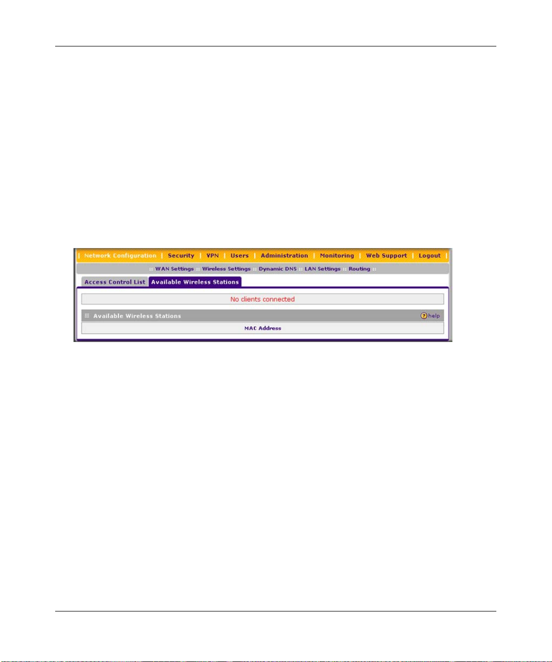
ProSafe Wireless-N VPN Firewall SRXN3205 Reference Manual
To manually add MAC address to the Trusted Wireless Station table on the Access Control List
screen:
1. Enter the MAC address in the MAC Address field of the Add New Trusted Station Manually
section of the screen. The MAC address should be in the xx:xx:xx:xx:xx:xx format.
You can usually find the MAC address printed on the bottom of the wireless adapter.
2. Click the Add button. Repeat these steps for each additional device you want to add to the
table.
To add the MAC address of an automatically discovered wireless station to the Trusted Wireless
Station table:
1. Click the Available Wireless Stations tab to the right of the Access Control List tab. The
Available Wireless Stations screen is displayed.
Figure 4-5
The Available Wireless Stations table displays any wireless stations that were discovered by
the VPN firewall within its range
1. Select the check box to the left of the entry that you want to add to the Trusted Wireless
Station table, or click select all to select all entries to the Trusted Wireless Station table.
2. Click the Add to Trusted List button. (Figure 4-5 does not show any buttons because there
are no wireless stations in the Available Wireless Stations table.)
To delete one ore more existing entries from the Trusted Wireless Station table on the Access
Control List screen:
1. Select the check box to the left of the entry that you want to delete, or click select all to select
all entries.
2. Click the delete button.
4-20 Wireless Configuration
v1.0, January 2010
Page 77

ProSafe Wireless-N VPN Firewall SRXN3205 Reference Manual
Chapter 5
Firewall Security and Content Filtering
This chapter describes how to set up your firewall and use the content filtering features of the
ProSafe Wireless-N VPN Firewall SRXN3205 to protect your network.
This chapter contains the following sections:
• “About Firewall Security and Content Filtering” on this page
• “Using Rules & Services to Block or Allow Traffic” on page 5-2
• “Configuring Other Firewall Features” on page 5-14
• “Creating Services, QoS Profiles, and Bandwidth Profiles” on page 5-19
• “Blocking Internet Sites (Content Filtering)” on page 5-25
• “Enabling Source MAC Filtering (Address Filtering)” on page 5-28
• “Configuring IP/MAC Address Binding” on page 5-29
• “Configuring Port Triggering” on page 5-31
• “Configuring UPnP (Universal Plug and Play)” on page 5-34
• “E-Mail Notifications of Event Logs and Alerts” on page 5-35
• “Administrator Tips” on page 5-36
About Firewall Security and Content Filtering
The VPN firewall provides you with Web content filtering options, plus browsing activity
reporting and instant alerts via e-mail. Network administrators can establish restricted access
policies based on time-of-day, Web addresses, and Web address keywords. You can also block
Internet access by applications and services, such as chat or games.
A firewall is a special category of router that protects one network (the “trusted” network, such as
your LAN) from another (the untrusted network, such as the Internet), while allowing
communication between the two. You can further segment keyword blocking to certain known
groups (see “Managing Groups and Hosts (LAN Groups)” on page 3-5 to set up LAN Groups).
A firewall incorporates the functions of a NAT (Network Address Translation) router, while
adding features for dealing with a hacker intrusion or attack, and for controlling the types of traffic
that can flow between the two networks. Unlike simple Internet sharing NAT routers, a firewall
Firewall Security and Content Filtering 5-1
v1.0, January 2010
Page 78

ProSafe Wireless-N VPN Firewall SRXN3205 Reference Manual
uses a process called stateful packet inspection to protect your network from attacks and
intrusions. NAT performs a very limited stateful inspection in that it considers whether the
incoming packet is in response to an outgoing request, but true Stateful Packet Inspection goes far
beyond NAT.
Using Rules & Services to Block or Allow Traffic
This section includes the following topics:
• “Services-Based Rules” on this page
• “Viewing the Firewall Rules” on page 5-7
• “Order of Precedence for Rules” on page 5-7
• “Setting the Outbound Policy” on page 5-7
• “Creating a LAN WAN Outbound Services Rule” on page 5-8
• “Creating a LAN WAN Inbound Services Rule” on page 5-9
• “Inbound Rules Examples” on page 5-11
• “Outbound Rules Example” on page 5-14
Firewall rules and services are used to block or allow specific traffic passing through from one side
to the other. Inbound rules (WAN to LAN) restrict access by outsiders to private resource s,
selectively allowing only specific outside users to access specific resources. Outbound rules (LAN
to WAN) determine what outside resources local users can have access to.
A firewall has two default rules, one for inbound traffic and one for outbound traffic. The default
rules of the VPN firewall are:
• Inbound. Block all access from outside except responses to requests from the LAN side.
• Outbound. Allow all access from the LAN side to the outside.
User-defined firewall rules for blocking or allowing traffic on the VPN firewall can be applied to
inbound or outbound traffic.
Services-Based Rules
The rules to block traffic are based on the traffic’s category of service.
• Outbound Rules (service blocking). Outbound traffic is normally allowed unless the firewall
is configured to disallow it.
5-2 Firewall Security and Content Filtering
v1.0, January 2010
Page 79

ProSafe Wireless-N VPN Firewall SRXN3205 Reference Manual
• Inbound Rules (port forwarding). Inbound traffic is normally blocked by the firewall unless
the traffic is in response to a request from the LAN side. The firewall can be configured to
allow this otherwise blocked traffic.
• Customized Services. Additional services can be added to the list of services in the factory
default list. These added services can then have rules defined for them to either allow or block
that traffic (see “Adding Customized Services” on page 5-19).
• Quality of Service (QoS) priorities. Each service at its own native priority that impacts its
quality of performance and tolerance for jitter or delays. You can change this QoS priority if
desired to change the traffic mix through the system (see “Setting Quality of Service (QoS)
Priorities” on page 5-21).
Outbound Rules (Service Blocking)
The VPN firewall allows you to block the use of certain Internet services by PCs on your network.
This is called service blocking or port filtering.
Note: See “Enabling Source MAC Filtering (Address Filtering)” on page 5-28 for yet
another way to block outbound traffic from selected PCs that would otherwise be
allowed by the firewall.
Table 5 -1. Outbound Rules
Item Description
Service Select the desired service or application to be covered by this rule. If the desired service
or application does not appear in the list, you must define it using the Services screen
(see “Adding Customized Services” on page 5-19).
Action Select the desired action for outgoing connections covered by this rule:
• BLOCK always
• BLOCK by schedule, otherwise Allow
• ALLOW always
• ALLOW by schedule, otherwise Block
Note: Any outbound traffic that is not blocked by rules you create will be allowed by the
default rule.
ALLOW rules are only useful if the traffic is already covered by a BLOCK rule. That is, you
wish to allow a subset of traffic that is currently blocked by another rule.
Select Schedule Select the desired time schedule (Schedule1, Schedule2, or Schedule3) that will be used
by this rule.
• This pull-down menu gets activated only when “BLOCK by schedule, otherwise Allow”
or “ALLOW by schedule, otherwise Block” is selected as Action.
• Use a Schedule screen to configure the time schedules (see “Setting Schedules to
Block or Allow Specific Traffic” on page 5-24).
Firewall Security and Content Filtering 5-3
v1.0, January 2010
Page 80

ProSafe Wireless-N VPN Firewall SRXN3205 Reference Manual
Table 5-1. Outbound Rules (continued)
Item Description
LAN Users Th ese settin gs determine which computers on your network are affected by this rule.
Select the desired options:
• Any – All PCs and devices on your LAN.
• Single address – Enter the required address and the rule will be applied to that
particular PC.
• Address range – If this option is selected, you must enter the start and finish fields.
• Groups – Select the Group to which this rule will apply. Use the (under Network
Configuration) to assign PCs to Groups. See “Managing Groups and Hosts (LAN
Groups)” on page 3-5.
WAN Users These settings determine which Internet locations are covered by the rule, based on their
IP address. Select the desired option:
• Any – All Internet IP address are covered by this rule.
• Single address – Enter the required address in the start field.
• Address range – If this option is selected, you must enter the start and end fields.
QoS Priority This setting determines the priority of a service which, in turn, determi nes the quality of
that service for the traffic passing through the firewall. By default, the priority shown is that
of the selected service. The user can change it accordi ngly. If the user does not make a
selection (leaves it as Normal-Service), then the native priority of the service will be
applied to the policy. See “Setting Quality of Service (QoS) Priorities” on page 5-21.
Log This determines whether packets covered by this rule are logged. Select the desired
action:
• Always – always log traffic considered by this rule, whether it matches or not. This is
useful when debugging your rules.
• Never – never log traffic considered by this rule, whether it matches or not.
Bandwidth
Profile
NAT Single IP Is
On (interface)
Specifies the name of a bandwidth limiting profile. Using a bandwidth profile, bandwidth
consumed by different connections can be limited. If multiple connections correspond to
the same firewall rule, they will share the same bandwidth limiting. See “Creating
Bandwidth Profiles” on page 5-21.
Specifies to which WAN interface the NAT IP address belongs. All outgoing packets will
be routed through the specified WAN interface only.
Inbound Rules (Port Forwarding)
When the VPN firewall uses Network Address Translation (NAT), your network presents only one
IP address to the Internet and outside users cannot directly address any of your local computers.
However, by defining an inbound rule you can make a local server (for example, a Web server or
game server) visible and available to the Internet. The rule tells the firewall to direct inbound
traffic for a particular service to one local server based on the destination port number. This is al so
known as port forwarding.
5-4 Firewall Security and Content Filtering
v1.0, January 2010
Page 81
ProSafe Wireless-N VPN Firewall SRXN3205 Reference Manual
Whether or not DHCP is enabled, how the PCs will access the server’s LAN address impacts the
inbound rules. For example:
• If your external IP address is assigned dynamically by your ISP (DHCP enabled), the IP
address may change periodically as the DHCP lease expires. Consider using dynamic DNS so
that external users can always find your network (see “Configuring Dynamic DNS” on page 2-
12).
• If the IP address of the local server PC is assigned by DHCP, it may change when the PC is
rebooted. To avoid this, use the Reserved IP address feature to keep the PC’s IP address
constant (see “Configuring DHCP Address Reservation” on page 3-9).
• Local PCs must access the local server using the server’s local LAN address. Attempts by
local PCs to access the server using the external WAN IP address will fail.
Note: See “Configuring Port Triggering” on page 5-31 for yet another way to allow
certain types of inbound traffic that would otherwise be blocked by the
firewall.
Table 5-2. Inbound Rules
Item Description
Service Select the desired service or application to be covered by this rule. If the desired service
or application does not appear in the list, you must define it using the Services screen
(see “Adding Customized Services” on page 5-19).
Action Select the desired action for packets covered by this rule:
• BLOCK always
• BLOCK by schedule, otherwise Allow
• ALLOW always
• ALLOW by schedule, otherwise Block
Note: Any inbound traffic which is not allowed by rules you create will be blocked by the
Default rule.
Select Schedule Select the desired time schedule (Schedule1, Schedule2, or Schedule3) that will be used
by this rule (see “Setting Schedules to Block or Allow Specific Traffic” on page 5-24).
• This pull-down menu gets activated only when “BLOCK by schedule, otherwise Allow”
or “ALLOW by schedule, otherwise Block” is selected as Action.
• Use a Schedule screen to configure the time schedules.
Send to LAN
Server
This field appears only with NAT routing (not classical routing). This LAN address or
range of LAN addresses determines which computer or computers on your network are
hosting this service rule. (You can also translate these addresses to a port number.)
Firewall Security and Content Filtering 5-5
v1.0, January 2010
Page 82

ProSafe Wireless-N VPN Firewall SRXN3205 Reference Manual
Table 5-2. Inbound Rules (continued)
Item Description
Translate to Port
Number
WAN
Destination IP
Address
LAN Users Th ese settin gs determine which computers on your network are affected by this rule.
WAN Users These settings determine which Internet locations are covered by the rule, based on their
Log This determines whether packets covered by this rule are logged. Select the desired
Bandwidth
Profile
Check this box and enter a port number to assign the LAN server to a different service
port number. Inbound traffic to the service port will have the destination port number
modified to the port number configured here.
This setting determines the destination IP address applicable to incoming traffic.
This is the public IP address that will map to the internal LAN server; it can either be the
address of the WAN port, another public IP address, or an address range.
Select the desired options:
• Any – All PCs and devices on your LAN.
• Single address – Enter the required address and the rule will be applied to that
particular PC.
• Address range – If this option is selected, you must enter the start and finish fields.
• Groups – Select the Group to which this rule will apply. Use the (under Network
Configuration) to assign PCs to Groups. See “Managing Groups and Hosts (LAN
Groups)” on page 3-5.
IP addresses. Select the desired option:
• Any – All Internet IP address are covered by this rule.
• Single address – Enter the required address in the start field.
• Address range – If this option is selected, you must enter the start and end fields.
action:
• Always – Always log traffic considered by this rule, whether it matches or not. This is
useful when debugging your rules.
• Never – Never log traffic considered by this rule, whether it matches or not.
Specifies the name of a bandwidth limiting profile. Using a bandwidth profile, bandwidth
consumed by different connections can be limited. If multiple connections correspond to
the same firewall rule, they will share the same bandwidth limiting. See “Creating
Bandwidth Profiles” on page 5-21.
Note: Some residential broadband ISP accounts do not allow you to run any server
processes (such as a Web or FTP server) from your location. Your ISP may
periodically check for servers and may suspend your account if it discovers any
active services at your location. If you are unsure, refer to the Acceptable Use
Policy of your ISP.
Remember that allowing inbound services opens holes in your VPN firewall. Only enable those
ports that are necessary for your network. It is also advisable to turn on the server application
security and invoke the user password or privilege levels, if provided.
5-6 Firewall Security and Content Filtering
v1.0, January 2010
Page 83

ProSafe Wireless-N VPN Firewall SRXN3205 Reference Manual
Viewing the Firewall Rules
To view the firewall rules, go to Security > Firewall from the main/submenu. The LAN WAN
Rules screen displays (Figure 5-1 shows some examples).
Figure 5-1
Order of Precedence for Rules
As you define new rules, they are added to the tables in the LAN WAN Rules screen as the last
item in the list, as shown in Figure 5-1. For any traffic attempting to pass through the firewall, the
packet information is subjected to the rules in the order shown in the Outbound Services and
Inbound Services rules tables, beginning at the top and proceeding to the bottom, before applying
the default rule. In some cases, the order of precedence of two or more rules may be important in
determining the disposition of a packet. For example, you should place the most strict rules at the
top (those with the most specific services or addresses). The up and down buttons allow you to
relocate a defined rule to a new position in the table.
Setting the Outbound Policy
The default outbound policy is to allow all traffic to the Internet to pass through. Firewall rules can
then be applied to block specific types of traffic from going out from the LAN to the Internet
(Outbound). The default policy of Allow Always can be changed to block all outbound traffic
which then allows you to enable only specific services to pass through the VPN firewall.
Firewall Security and Content Filtering 5-7
v1.0, January 2010
Page 84

ProSafe Wireless-N VPN Firewall SRXN3205 Reference Manual
To change the default outbound policy, follow these steps:
1. Go to the LAN WAN Rules screen, shown in Figure 5-1 on page 5-7.
2. Add the outbound rules you plan to use.
3. Change the outbound policy by choosing Block Always from the pull-down menu.
4. Click Apply.
Creating a LAN WAN Outbound Services Rule
An outbound rule will block or allow the selected application from an internal IP LAN address to
an external WAN IP address according to the schedule created on the Schedule screen.
You can also tailor these rules to your specific needs (see “Administrator Tips” on page 5-36).
Note: This feature is for advanced administrators only! Incorrect configuration will cause
serious problems.
To create a new outbound service rule in the LAN WAN Rules screen:
1. In the LAN W AN Rules screen, click add under the Outbound Services table. The Add LAN
WAN Outbound Service screen is displayed.
Figure 5-2
5-8 Firewall Security and Content Filtering
v1.0, January 2010
Page 85

ProSafe Wireless-N VPN Firewall SRXN3205 Reference Manual
2. Configure the settings as explained in Table 5-1 on page 5-3.
3. Click Apply to save your changes. The new rule is added to the Outbound Services table on
the LAN WAN Rules screen.
Creating a LAN WAN Inbound Services Rule
The Inbound Services table lists all existing rules for inbound traffic. If you have not defined any
rules, no rules will be listed. By default, all inbound traffic is blocked. Remember that allowing
inbound services opens holes in your firewall. Only enable those ports that are necessary for your
network.
To create a new inbound service rule in the LAN WAN Rules screen:
1. In the LAN WAN Rules screen, click add under the Inbound Services table. The Add LAN
WAN Inbound Service screen is displayed.
Figure 5-3
2. Configure the settings as explained in Table 5-2 on page 5-5.
3. Click Apply to save your changes. The new rule is added to the Inboun d Services table on th e
LAN WAN Rules screen.
Firewall Security and Content Filtering 5-9
v1.0, January 2010
Page 86

ProSafe Wireless-N VPN Firewall SRXN3205 Reference Manual
Modifying Rules
To make changes to an existing outbound or inbound service rule on the the LAN WAN Rules
screen, in the Action column to the right of to the rule, click on of the following table buttons:
• edit. Allows you to make any changes to the rule definition of an existing rule. Depending on
your selection, either the Edit LAN WAN Outbound Service screen (identical to Figure 5-2 on
page 5-8) or Edit LAN WAN Inbound Service screen (identical to Figure 5-3 on page 5-9)
displays, containing the data for the selected rule.
• up. Moves the rule up one position in the table rank.
• down. Moves the rule down one position in the table rank.
To enable, disable, or delete one or more rules:
1. Select the checkbox to the left of the rule that you want to delete or disable or click the select
all table button to select all rules.
2. Click one of the following table buttons:
• enable. Enables the rule or rules. The “!” status icon changes from a grey circle to a green
circle, indicating that the rule is or rules are enabled. (By default, when a rule is added to
the table, it is automatically enabled.)
• disable. Disables the rule or rules. The “!” status icon changes from a green circle to a
grey circle, indicating that the rule is or rules are disabled.
• delete. Deletes the rule or rules.
5-10 Firewall Security and Content Filtering
v1.0, January 2010
Page 87

ProSafe Wireless-N VPN Firewall SRXN3205 Reference Manual
Inbound Rules Examples
LAN WAN Inbound Rule: Hosting a Local Public Web Server
If you host a public W e b server on your local network, you can define a rule to allow inbound Web
(HTTP) requests from any outside IP address to the IP address of your Web server at any time of
day.
In the example shown in Figure 5-4, unrestricted access is provided from the Internet to the local
Web server at LAN IP address 192.168.1.99.
Figure 5-4
LAN WAN Inbound Rule: Allowing Videoconference from Restricted Addresses
If you want to allow incoming videoconferencing to be initiated from a restricted range of outside
IP addresses, such as from a branch office, you can create an inbound rule.
In the example shown in Figure 5-5 on page 5-12, CU-SeeMe connections are allowed to a local
host only from a specified range of external IP addresses. Connections are blocked during the
period specified by Schedule 1.
Firewall Security and Content Filtering 5-11
v1.0, January 2010
Page 88

ProSafe Wireless-N VPN Firewall SRXN3205 Reference Manual
Figure 5-5
LAN WAN Inbound Rule: Setting Up One-to-One NAT Mapping
If you arrange with your ISP to have more than one public IP address for your use, you can use the
additional public IP addresses to map to servers on your LAN. One of these public IP addresses
will be used as the primary IP address of the VPN firewall. This address will be used to provide
Internet access to your LAN PCs through NAT. The other addresses are available to map to your
servers.
In the example shown in Figure 5-6 on page 5-13, we have configured multi-NAT to support
multiple public IP addresses on one WAN interface. The inbound rule instructs the VPN firewall
to host an additional public IP address (10.1.0.5) and to associate this address with the W eb server
on the LAN (at 192.168.0.1). We also instruct the VPN firewall to translate the incoming HTTP
port number (port 80) to a different port number (port 8080).
The following addressing scheme is used in this example:
• VPN firewall:
– WAN primary public IP address: 10.1.0.1
– WAN additional public IP address: 10.1.0.5
– LAN IP address 192.168.1.1
5-12 Firewall Security and Content Filtering
v1.0, January 2010
Page 89

ProSafe Wireless-N VPN Firewall SRXN3205 Reference Manual
• Web server PC on the VPN firewall’s LAN
– LAN IP address: 192.168.1.11
– Port number for Web service: 8080
Figure 5-6
To test the connection from a PC on the WAN side, type http://10.1.0.5. The home page of the
Web server should appear.
LAN WAN Inbound Rule: Specifying an Exposed Host
Specifying an exposed host allows you to set up a computer or server that is available to anyone on
the Internet for services that you have not yet defined.
To expose one of the PCs on your LAN as this host:
1. Create an inbound rule that allows all protocols.
2. Place the new rule below all other inbound rules.
Note: For security, NETGEAR strongly recommends that you avoid creating an exposed
host. When a computer on your LAN is designated as the exposed host, it loses
much of the protection of the firewall and is exposed to many exploits from the
Internet. If compromised, the computer can be used to attack your network.
Firewall Security and Content Filtering 5-13
v1.0, January 2010
Page 90

ProSafe Wireless-N VPN Firewall SRXN3205 Reference Manual
Outbound Rules Example
Outbound rules let you prevent users from using applications such as Instant Messenger, Real
Audio, or other non-essential services.
LAN WAN Outbound Rule: Blocking Instant Messenger
To block Instant Messenger usage by employees during working hours, you can create an
outbound rule to block that application from any internal IP address to any external address
according to the schedule that you have created on the Schedule screen. You can also have the
firewall log any attempt to use Instant Messenger during that blocked period.
Figure 5-7
Configuring Other Firewall Features
You can configure attack checks, set session limits, and manage the Application Level Gateway
(ALG) for SIP sessions.
Attack Checks
The Attack Checks screen allows you to specify whether or not the VPN firewall should be
protected against common attacks in the LAN and WAN networks.
5-14 Firewall Security and Content Filtering
v1.0, January 2010
Page 91

ProSafe Wireless-N VPN Firewall SRXN3205 Reference Manual
To enable the appropriate Attack Checks for your environment:
1. Select Security > Firewall from the main/submenu.
2. Click the Attack Checks tab. The Attack Checks screen is displayed.
Figure 5-8
3. Check the boxes for the Attack Checks you wish to monitor. The various types of attack
checks are listed and defined below.
4. Click Apply to save your settings.
The various types of attack checks listed on the Attack Checks screen are:
• WAN Security Checks
– Respond To Ping On Internet Ports. By default, the VPN firewall responds to an ICMP
Echo (ping) packet coming from the Internet or WAN side. Responding to a ping can be a
useful diagnostic tool when there are connectivity problems. If the ping option is enabled,
you can allow either any IP address or a specific IP address only to respond to a ping. You
can disable the ping option to prevent hackers from easily discovering the VPN firewall
via a ping.
– Enable Stealth Mode. In stealth mode, the VPN firewall will not respond to port scans
from the WAN, thus making it less susceptible to discovery and attacks.
Firewall Security and Content Filtering 5-15
v1.0, January 2010
Page 92

ProSafe Wireless-N VPN Firewall SRXN3205 Reference Manual
– Block TCP Flood. A SYN flood is a form of denial of service attack in which an attacker
sends a succession of SYN requests to a target system. When the system responds, the
attacker does not complete the connection, thus saturating the server with half-open
connections. No legitimate connections can then be made.
When blocking is enabled, the VPN firewall will limit the lifetime of partial connections
and will be protected from a SYN flood attack.
• LAN Security Checks
– Block UDP flood. A UDP flood is a form of denial of service attack that can be initiated
when one machine sends a large number of UDP packets to random ports on a remote
host. As a result, the distant host will (1) check for the application listening at that port, (2)
see that no application is listening at that port, and (3) reply with an ICMP Destination
Unreachable packet.
When the victimized system is flooded, it is forced to send many ICMP packets,
eventually making it unreachable by other clients. The attacker may also spoof the IP
address of the UDP packets, ensuring that the excessive ICMP return packets do not reach
him, thus making the attacker’s network location anonymous.
If flood checking is enabled, the VPN firewall will not accept more than 20 simultaneous,
active UDP connections from a single computer on the LAN.
– Disable Ping Reply on LAN Ports. T o prevent the VPN firewall from responding to Ping
requests from the LAN, click this checkbox.
• VPN Pass through. When the VPN firewall is in NAT mode, all packets going to the remote
VPN gateway are first filtered through NAT and then encrypted per the VPN policy.
For example, if a VPN Client or Gateway on the LAN side of this VPN firewall wants to
connect to another VPN endpoint on the WAN (placing this VPN firewall between two VPN
end points), encrypted packets are sent to this VPN firewall. Since this VPN firewall filters the
encrypted packets through NAT, the packets become invalid unless VPN pass through is
enabled.
IPSec, PPTP, and L2TP represent different types of VPN tunnels that can pass through the
VPN firewall. T o allow the VPN traffic to pass through without filtering, enable those options
for the type of tunnel(s) that will pass through the VPN firewall. By default, IPSec, PPTP, and
L2TP are selected.
5-16 Firewall Security and Content Filtering
v1.0, January 2010
Page 93

ProSafe Wireless-N VPN Firewall SRXN3205 Reference Manual
Configuring Session Limits
To prevent one user or group from using excessive system resources, you can limit the total
number of IP sessions allowed through the VPN firewall for an individual or group. You can
specify the maximum number of sessions by either a percentage of maximum sessions or an
absolute number of maximum sessions. Session limiting is disabled by default.
To configure session limits:
1. Select Security > Firewall from the main/submenu.
2. Click the Session Limit tab. The Session Limit screen is displayed.
Figure 5-9
3. Click the Yes radio button under Do you want to enable Session Limit?
4. From the User Limit Parameter drop-down list, define the maximum number of sessions per
IP either as a percentage of maximum sessions or as an absolute.
The percentage is computed on the total connection capacity of the device.
5. Enter the User Limit. If the User Limit Parameter is set to Percentage of Max Sessions, this
is the maximum number of sessions allowed from a single source machine as a percentage of
the total connection capacity. (Session Limit is per machine based.) Otherwise, if the User
Limit Parameter is set to Number of Sessions, the user limit is an absolute value.
Firewall Security and Content Filtering 5-17
v1.0, January 2010
Page 94

ProSafe Wireless-N VPN Firewall SRXN3205 Reference Manual
Note: Some protocols (such as FTP or RSTP) create two sessions per connection
which should be considered when configuring Session Limiting.
The Total Number of Packets Dropped due to Session Limit field shows total number of
packets dropped when session limit is reached.
6. In the Session Timeout section, modify the TCP, UDP and ICMP timeout values as you
require. A session will expire if no data for the session is received for the duration of the
timeout value. The default timeout values are 1200 seconds for TCP sessions, 180 seconds for
UDP sessions, and 8 seconds for ICMP sessions.
7. Click Apply to save your settings.
To monitor session limiting, return to this screen periodically and check the display of Total
Number of Packets Dropped due to Session Limit, which indicates that session limits have been
reached.
Managing the Application Level Gateway for SIP Sessions
The Application Level Gateway (ALG) facilitates multimedia sessions such as voice over IP
(VoIP) sessions that use the Session Initiation Protocol (SIP) across the firewall and provides
support for multiple SIP clients. ALG support for SIP is disabled by default.
To enable ALG for SIP:
1. Select Security > Firewall from the main/submenu.
1. Click the Advanced tab. The Advanced screen is displayed.
Figure 5-10
2. Select the Enable SIP ALG checkbox.
3. Click Apply to save your settings.
5-18 Firewall Security and Content Filtering
v1.0, January 2010
Page 95

ProSafe Wireless-N VPN Firewall SRXN3205 Reference Manual
Creating Services, QoS Profiles, and Bandwidth Profiles
When you create inbound and outbound firewall rules, you use firewall objects such as services,
QoS profiles, bandwidth profiles, and schedules to narrow down the firewall rules:
• Services. A service narrows down the firewall rule to an application and a port number. For
information about adding services, see “Adding Customized Services” on page 5-19.
• QoS profiles. A quality of service (QoS) profile defines the relative priority of an IP packet
for traffic that matches the firewall rule. For information about creating QoS profiles, see
“Setting Quality of Service (QoS) Priorities” on page 5-21.
• Bandwidth Profiles. A bandwidth profile allocates and limits traffic bandwidth for the LAN
users to which a firewall rule is applied. For information about creating bandwidth profiles,
see “Creating Bandwidth Profiles” on page 5-21.
Note: A schedule narrows down the period during which a firewall rule is applied. For
information about specifying schedules, see “Setting Schedules to Block or Allow
Specific Traffic” on page 5-24.
Adding Customized Services
Services are functions performed by server computers at the request of client computers. For
example, Web servers serve Web pages, time servers serve time and date information, and game
hosts serve data about other players’ moves. When a computer on the Internet sends a request for
service to a server computer, the requested service is identified by a service or port number. This
number appears as the destination port number in the transmitted IP packets. For example, a packet
that is sent with destination port number 80 is an HTTP (Web server) request.
The service numbers for many common protocols are defined by the Internet Engineering Task
Force (IETF) and published in RFC1700, “Assigned Numbers.” Service numbers for other
applications are typically chosen from the range 1024 to 65535 by the authors of the application.
Although the VPN firewall already holds a list of many service port numbers, you are not limited
to these choices. Use the Services screen to add additional services and applications to the list for
use in defining firewall rules. The Services screen shows a list of services that you have defined, as
shown in Figure 5-11 on page 5-20.
To define a new service, first you must determine which port number or range of numbers is used
by the application. This information can usually be determined by contacting the publisher of the
application or from user groups or newsgroups. When you have the port number information, you
can enter it on the Services screen.
Firewall Security and Content Filtering 5-19
v1.0, January 2010
Page 96

ProSafe Wireless-N VPN Firewall SRXN3205 Reference Manual
To add a custom service:
1. Select Security > Services from the main/submenu. The Services screen is displayed.
Figure 5-11
2. In the Add Custom Services section, enter a descriptive name for the service (this name is for
your convenience).
3. Select the Layer 3 transport protocol of the service: TCP, UDP, or ICMP.
4. Enter the first TCP or UDP port of the range that the service uses.
5. Enter the last port of the range that the service uses. If the service only uses a single port
number, enter the same number in both fields.
6. Click Add. The new custom service will be added to the Custom Services Table.
Modifying a Service
To edit the settings of an existing service:
1. In the Custom Services Table, click the edit button adjacent to the service you want to edit.
The Edit Service screen is displayed.
2. Modify the settings that you wish to change.
3. Click Apply to confirm your changes. The modified service is displayed in the Custom
Services Table.
5-20 Firewall Security and Content Filtering
v1.0, January 2010
Page 97

ProSafe Wireless-N VPN Firewall SRXN3205 Reference Manual
Setting Quality of Service (QoS) Priorities
The QoS setting determines the priority of a service, which in turn determines the quality of that
service for the traffic passing through the firewall. You can change the QoS Priority:
• On the Services screen in the Custom Services Table for customized services (see
Figure 5-11 on page 5-20).
• On the Add LAN WAN Outbound Services screen (see Figure 5-2 on page 5-8).
The QoS priority definition for a service determines the queue that is used for the traffic passing
through the VPN firewall. A priority is assigned to IP packets using this service. Priorities are
defined by the “Type of Service (ToS) in the Internet Protocol Suite” standards, RFC 1349. A ToS
priority for traffic passing through the VPN firewall is one of the following:
• Normal-Service. No special priority given to the traffic. The IP packets for services with this
priority are marked with a ToS value of 0.
• Minimize-Cost. Used when data has to be transferred over a link that has a lower “cost”. The
IP packets for services with this priority are marked with a ToS value of 1.
• Maximize-Reliability. Used when data needs to travel to the destination over a reliable link
and with little or no retransmission. The IP packets for services with this priority are marked
with a ToS value of 2.
• Maximize-Throughput. Used when the volume of data transferred during an interval is
important even if the latency over the link is high. The IP packets for services with this priority
are marked with a ToS value of 4.
• Minimize-Delay. Used when the time required (latency) for the packet to reach the destination
must be low. The IP packets for services with this priority are marked with a ToS value of 8.
Creating Bandwidth Profiles
Bandwidth limiting determines the way in which data is communicated with your host. The
purpose of bandwidth limiting is to provide a method for limiting traffic, thus preventing LAN
users from consuming all the bandwidth on your WAN link. Bandwidth limiting is done on the
available WAN interface.
As an example: when a new connection is established by a device, the device will locate the
firewall rule corresponding to the connection.
• If the rule has a bandwidth profile specification, then the device will create a bandwidth class
in the kernel.
• If multiple connections correspond to the same firewall rule, they will share the same class.
Firewall Security and Content Filtering 5-21
v1.0, January 2010
Page 98

ProSafe Wireless-N VPN Firewall SRXN3205 Reference Manual
An exception occurs for an individual bandwidth profile if the classes are per source IP . The source
IP is the IP of the first packet of the connection:
The class is deleted when all the connections using the class expire.
To add a bandwidth profile:
1. Select Security > Bandwidth Profile from the main/submenu. The Bandwidth Profile screen
is displayed.
Figure 5-12
2. Click Add to add a new bandwidth profile. The Add New Bandwidth Profile screen is
displayed.
Figure 5-13
5-22 Firewall Security and Content Filtering
v1.0, January 2010
Page 99

ProSafe Wireless-N VPN Firewall SRXN3205 Reference Manual
3. Enter the following information:
a. Enter a Profile Name. This name will become available in the firewall rules definition
menus.
b. From the Direction pull-down box, select whether the profile will apply to outbound,
inbound, or both outbound and inbound traffic.
c. Depending on the direction that you selected, enter the minimum and maximum
bandwidths to be allowed:
• Enter the Outbound Minimum Bandwidth and Outbound Maximum Bandwidth
in Kbps.
• Enter the Inbound Minimum Bandwidth and Inbound Maximum Bandwidth in
Kbps.
The minimum bandwidth can range from 0 Kbps to the maximum bandw idth that you
specify. The maximum bandwidth can range from 100 Kbps to 100,000 Kbps.
d. From the Type pull-down box, select whether the profile will apply to a group or
individual.
e. From the WAN pull-down box, specify the WAN interface (if in Load Balancing Mode)
for the profile.
• Click Apply. The new bandwidth profile will be added to the List of Bandwidth Pr ofiles
table.
To edit a Bandwidth Profile:
1. Click the Edit link adjacent to the profile you want to edit. The Edit Bandwidth Profile screen
is displayed.
2. Modify the settings that you wish to change.
3. Click Apply. Your modified profile will display in the Bandwidth Profile table.
To remove an entry from the table, select the profile and click delete.
To remove all the profiles, click select all and then click delete.
Firewall Security and Content Filtering 5-23
v1.0, January 2010
Page 100

ProSafe Wireless-N VPN Firewall SRXN3205 Reference Manual
Setting Schedules to Block or Allow Specific Traffic
If you enabled content filtering on the Block Sites screen, or if you defined an outbound or
inbound rule to use a schedule, you can set up a schedule for when blocking occurs or when access
is restricted. The firewall allows you to specify when blocking will be enforced by configuring one
of the Schedules—Schedule 1, Schedule 2 or Schedule 3.
To invoke rules and block keywords or Internet dom ains based on a schedule:
1. Select Security > Schedule from the main/submenu.
The Schedule 1 screen is displayed as the default selection, along with tabs for Schedules 2
and 3. .
Figure 5-14
2. Check the radio button for All Days or Specific Days. If you chose Specific Days, check the
radio button for each day you want the schedule to be in effect.
3. Check the radio button to schedule the time of day: All Day, or Specific Times. If you chose
Specific Times, enter the Start Time and End Time fields (Hour, Minute, AM/PM), which
will limit access during certain times for the selected days.
4. Click Apply to save your settings to Schedule 1.
Repeat this procedure to set schedules for Schedule 2 and Schedule 3.
5-24 Firewall Security and Content Filtering
v1.0, January 2010
 Loading...