

Page 1
ProSafe Gigabit Quad WAN SSL VPN Firewall SRX5308
Reference Manual
350 East Plumeria Drive
San Jose, CA 95134
USA
July, 2012
202-10536-04
v1.0
Page 2

ProSafe Gigabit Quad W AN SSL VPN Firewall SRX5308
© 2010–2012 NETGEAR, Inc. All rights reserved.
No part of this publication may be reproduced, transmitted, transcribed, stored in a retrieval system, or translated
into any language in any form or by any means without the written permission of NETGEAR, Inc.
Technical Support
Thank you for choosing NETGEAR. T o register your product, get the latest product updates, get support online, or
for more information about the topics covered in this manual, visit the Support website at
http://support.netgear.com.
Phone (US & Canada only): 1-888-NETGEAR
Phone (Other Countries): Check the li
http://support.netgear.com/app
st of phone numbers at
/answers/detail/a_id/984.
Trademarks
NETGEAR, the NETGEAR logo, and Connect with Innovation are trademarks and/or registered trademarks of
NETGEAR, Inc. and/or its subsidiaries in the United States and/or other countries. Information is subject to change
without notice. Other brand and product names are registered trademarks or trademarks of their respective
holders. © 2010–2012 NETGEAR, Inc. All rights reserved.
Statement of Conditions
To improve internal design, operational function, and/or reliability, NETGEAR reserves the right to make changes
to the products described in this document without notice. NETGEAR does not assume any liability that may occur
due to the use, or application of, the product(s) or circuit layout(s) described herein.
Revision History
Publication
Part Number
202-10536-04 1.0 July 2012 A major revision. Added the following features:
202-10536-03 1.0 November 2011 Incorporated nontechnical edits only (there are no feature
Version Publish Date Comments
• Support for IPv6 with multiple IPv6 features, including a new
general menu structure that provides both IPv4 and IPv6 radio
buttons (very extensive revisions throughout the manual)
• IPSec VPN autoinitia
VPN Policy)
• SNMPv3 support (see Use a Simple Network Management
Protocol Manager)
• Option to reboot with a different firmware version (see Select
the Firmware and Reboot the VPN Firewall )
• Extensive list of factory d
Default Settings and Technical Specifications)
chan
ges).
te support (see Manually Add or Edit a
efault settings (see Appendix A,
2
Page 3

ProSafe Gigabit Quad WAN SSL VPN Firewall SRX5308
202-10536-02 1.0 July 2011 Added new features that are documented in the following
sections:
• Configure WAN QoS Profiles
• Inbound Rules (Port Forwarding) and Create LAN WAN Inbound
Service Rules
• Attack Checks
• Set Limits for IPv4 Sessions
• Create IP Groups
• Use the NETGEAR VPN Client Wizard to Create a Secure
Connection
• Manually Create a Secure Conne
VPN Client
• Configure the ProSafe VPN Client for Mode Config Operation
• Configure Date and Time Service
• Configure and Enable the LAN Traffic Meter
202-10536-01 1.0 April 2010 Initial publication of this reference manual.
ction Using the NETGEAR
3
Page 4

Contents
Chapter 1 Introduction
What Is the ProSafe Gigabit Quad WAN SSL VPN Firewall SRX5308? . .11
Key Features and Capabilities . . . . . . . . . . . . . . . . . . . . . . . . . . . . . . . . . .12
Quad-WAN Ports for Increased Reliability and
Advanced VPN Support for Both IPSec and SSL. . . . . . . . . . . . . . . . . .13
A Powerful, True Firewall with Content Filtering
Security Features . . . . . . . . . . . . . . . . . . . . . . . . . . . . . . . . . . . . . . . . . .14
Autosensing Ethernet Connections with Auto Uplink
Extensive Protocol Support . . . . . . . . . . . . . . . . . . . . . . . . . . . . . . . . . .15
Easy Installation and Management . . . . . . .
Maintenance and Support . . . . . . . . . . . . . . . . . . . . . . . . . . . . . . . . . . .16
Package Contents . . . . . . . . . . . . . . . . . . . . . . . . . . . . . . . . . . . . . . . . . . .16
Hardware Features. . . . . . . . . . . . . . . . . . . . . . . . . . . . . . . . . . . . . . . . . . .17
Front Panel. . . . . . . . . . . . . . . . . . . . . . . . . . . . . . . . . . . . . . . . . . . . . . .17
Rear Panel . . . . . . . . . . . . . . . . . . . . . . . . . . . . . . . . . . . . . . . . . . . . . . .19
Bottom Panel with Product Label . . . . . . . . . . . . . . . . . . . . . . . . . . . . . .19
Choose a Location for the VPN Firewall. . . . . . . . . . . . . . . . . . . . . . . . . . .20
Use the Rack-Mounting Kit. . . . . . . . . . . . . . . . . . . . . . . . . . . . . . . . . . .20
Log In to the VPN Firewall . . . . . . . . . . . . . . . . . . . . . . . . . . . . . . . . . . . . .21
Web Management Interface Menu Layout . . . . . . . . . . . . . . . . . . . . . . . . .23
Requirements for Entering IP Addresses. . . . . . . . . . . . . . . . . . . . . . . . . .25
IPv4 . . . . . . . . . . . . . . . . . . . . . . . . . . . . . . . . . . . . . . . . . . . . . . . . . . . .25
IPv6 . . . . . . . . . . . . . . . . . . . . . . . . . . . . . . . . . . . . . . . . . . . . . . . . . . . .25
Load Balancing. . . . . . .13
. . . . . . . . . . . . . . . . . . .14
. . . . . . . . . . . . . . .14
. . . . . . . . . . . . . . . . . . . . .15
Chapter 2 IPv4 and IPv6 Internet and WAN Settings
Internet and WAN Configuration Tasks . . . . . . . . . . . . . . . . . . . . . . . . . . .26
Tasks to Set Up IPv4 Internet Connections
Tasks to Set Up an IPv6 Internet
Configure the IPv4 Internet Connection and W
Configure the IPv4 WAN Mode . .
Let the VPN Firewall Automatically Detect and
Configure an IPv4 Internet Connection
Manually Configure an IPv4 Internet
Configure Load Balancing or Auto-Rollover . . . . . . . . . . . . . . . . . . . . . .39
Configure Secondary WAN Addresses . . . . . . . . . . . . . . . . . . . . . . . . .46
Configure Dynamic DNS . . . . . . . . . . . . . . . . . . . . . . . . . . . . . . . . . . . .48
Configure the IPv6 Internet Connection and W
Configure the IPv6 Routing Mode . . . . . . . .
Use a DHCPv6 Server to Configure an IPv6 Internet Connection . . . . .54
4
Connection to Your ISPs . . . . . . . . . .27
. . . . . . . . . . . . . . . . . . . . . . . . . . . . .28
Connection. . . . . . . . . . . . . . . . . .33
to Your ISPs . . . . . . . . . . .27
AN Settings. . . . . . . . . . . .28
. . . . . . . . . . . . . . . . . . . . . . . . .30
AN Settings. . . . . . . . . . . .51
. . . . . . . . . . . . . . . . . . . . .52
Page 5

ProSafe Gigabit Quad WAN SSL VPN Firewall SRX5308
Configure a Static IPv6 Internet Connection. . . . . . . . . . . . . . . . . . . . . .57
Configure a PPPoE IPv6 Internet Connection . . . . . . . . . . . . . . . . . . . .60
Configure 6to4 Automatic Tunneling . . . . . . . . . . . . . . . . . . . . . . . . . . .63
Configure ISATAP Automatic Tunneling. . . . . . . . . . . . . . . . . . . . . . . . .64
View the Tunnel Status and IPv6 Addresses . . . . . . . . . . . . . . . . . . . . .66
Configure Stateless IP/ICMP Translation. . . . . . . . . . . . . . . . . . . . . . . .66
Configure Advanced WAN Options and Other Task
Configure WAN QoS Profiles . . . . . . . . . . . . . . . . . . . . . . . . . . . . . . . . . . .72
Additional WAN-Related Configuration Tasks . . . . . . . . . . . . . . . . . . . . . .78
Verify the Connection . . . . . . . . . . . . . . . . . . . . . . . . . . . . . . . . . . . . . . .78
What to Do Next. . . . . . . . . . . . . . . . . . . . . . . . . . . . . . . . . . . . . . . . . . . . .78
s. . . . . . . . . . . . . . . . .67
Chapter 3 LAN Configuration
Manage IPv4 Virtual LANs and DHCP Options . . . . . . . . . . . . . . . . . . . . .79
Port-Based VLANs . . . . . . . . . . . . . . . . . . . . . . . . . . . . . . . . . . . . . . . . .80
Assign and Manage VLAN Profiles. . . . . . . . . . . . . . . . . . . . . . . . . . . . .81
VLAN DHCP Options . . . . . . . . . . . . . . . . . . . . . . . . . . . . . . . . . . . . . . .82
Configure a VLAN Profile . . . . . . . . . . . . . . . . . . . . . . . . . . . . . . . . . . . .83
Configure VLAN MAC Addresses and LAN Advanced Settings. . . . . . .88
Configure IPv4 Multihome LAN IP Addresses on the Default VLAN . . . . .89
Manage IPv4 Groups and Hosts (IPv4 LAN Groups). . . . . . . . . . . . . . . . .91
Manage the Network Database . . . . . . . . . .
Change Group Names in the Network Database . . . . . . . . . . . . . . . . . .95
Set Up DHCP Address Reservation. . . . . . .
Manage the IPv6 LAN . . . . . . . . . . . . . . . . . . . . . . . . . . . . . . . . . . . . . . . .97
DHCPv6 Server Options. . . . . . . . . . . . . . . . . . . . . . . . . . . . . . . . . . . . .98
Configure the IPv6 LAN . . . . . . . . . . . . . . . . . . . . . . . . . . . . . . . . . . . . .99
Configure the IPv6 Router Advertisement Daemon and
Advertisement Prefixes for the LAN . . . . . . . . . . . . . . . . . . . . . . . . . . .104
Configure IPv6 Multihome LAN IP Addresses on the Default VLAN . . . .108
Enable and Configure the DMZ Port for IPv4 and IPv6 Traffic. . . . . . . . .109
DMZ Port for IPv4 Traffic . . . . . . . . . . . . . . . . . . . . . . . . . . . . . . . . . . .110
DMZ Port for IPv6 Traffic . . . . . . . . . . . . . . . . . . . . . . . . . . . . . . . . . . .113
Configure the IPv6 Router Advertisement Daemon and
Advertisement Prefixes for the DMZ. . . . . . . . . . . . . . . . . . . . . . . . . . .117
Manage Static IPv4 Routing. . . . . . . . . . . . . . . . . . . . . . . . . . . . . . . . . . .122
Configure Static IPv4 Routes . . . . . . . . . . . . . . . . . . . . . . . . . . . . . . . .122
Configure the Routing Information Protocol . . . . . . . . . . . . . . . . . . . . .124
IPv4 Static Route Example. . . . . . . . . . . . . . . . . . . . . . . . . . . . . . . . . .127
Manage Static IPv6 Routing. . . . . . . . . . . . . . . . . . . . . . . . . . . . . . . . . . .127
. . . . . . . . . . . . . . . . . . . . .92
. . . . . . . . . . . . . . . . . . . . .96
Chapter 4 Firewall Protection
About Firewall Protection . . . . . . . . . . . . . . . . . . . . . . . . . . . . . . . . . . . . .130
Administrator Tips. . . . . . . . . . . . . . . . . . . . . . . . . . . . . . . . . . . . . . . . .131
Overview of Rules to Block or Allow Specific K
Outbound Rules (Service Blocking) . . . . . . .
Inbound Rules (Port Forwarding) .
. . . . . . . . . . . . . . . . . . . . . . . . . . . .135
5
inds of Traffic . . . . . . . . .131
. . . . . . . . . . . . . . . . . . . .133
Page 6

ProSafe Gigabit Quad WAN SSL VPN Firewall SRX5308
Order of Precedence for Rules. . . . . . . . . . . . . . . . . . . . . . . . . . . . . . .139
Configure LAN WAN Rules . . . . . . . . . . . . . . . . . . . . . . . . . . . . . . . . . . . 140
Create LAN WAN Outbound Service Rules . . . . . . . . . . . . . . . . . . . . .143
Create LAN WAN Inbound Service Rules . . . . . . . . . . . . . . . . . . . . . .145
Configure DMZ WAN Rules . . . . . . . . . . . . . . . . . . . . . . . . . . . . . . . . . . .147
Create DMZ WAN Outbound Service Rules. . . . . . . . . . . . . . . . . . . . .149
Create DMZ WAN Inbound Service Rules . . . . . . . . . . . . . . . . . . . . . . 151
Configure LAN DMZ Rules. . . . . . . . . . . . . . . . . . . . . . . . . . . . . . . . . . . .153
Create LAN DMZ Outbound Service Rules . . . . . . . . . . . . . . . . . . . . .155
Create LAN DMZ Inbound Service Rules. . . . . . . . . . . . . . . . . . . . . . .157
Examples of Firewall Rules . . . . . . . . . . . . . . . . . . . . . . . . . . . . . . . . . . .159
Examples of Inbound Firewall Rules . . . . . . . . . . . . . . . . . . . . . . . . . .159
Examples of Outbound Firewall Rules . . . . .
Configure Other Firewall Features. . . . . . . . . . . . . . . . . . . . . . . . . . . . . .166
Attack Checks. . . . . . . . . . . . . . . . . . . . . . . . . . . . . . . . . . . . . . . . . . . .166
Set Limits for IPv4 Sessions. . . . . . . . . . . . . . . . . . . . . . . . . . . . . . . . .169
Manage the Application Level Gateway for S
Services, Bandwidth Profiles, and Q
Add Customized Services . . . . . . . . . . . . . . . . . . . . . . . . . . . . . . . . . .172
Create IP Groups . . . . . . . . . . . . . . . . . . . . . . . . . . . . . . . . . . . . . . . . .174
Create Bandwidth Profiles . . . . . . . . . . . . . . . . . . . . . . . . . . . . . . . . . . 176
Create Quality of Service Profiles for IPv4 Firewall Rules . . . . . . . . . .179
Quality of Service Priorities for IPv6 Firewall Rules . . . . . . . . . . . . . . .181
Configure Content Filtering . . . . . . . . . . . . . . . . . . . . . . . . . . . . . . . . . . .181
Set a Schedule to Block or Allow Specific Traffic
Enable Source MAC Filtering. . . . . . . . . . . . . . . . . . . . . . . . . . . . . . . . . .186
Set Up IP/MAC Bindings . . . . . . . . . . . . . . . . . . . . . . . . . . . . . . . . . . . . . 187
Configure Port Triggering. . . . . . . . . . . . . . . . . . . . . . . . . . . . . . . . . . . . .192
Configure Universal Plug and Play. . . . . . . . . . . . . . . . . . . . . . . . . . . . . . 194
oS Profiles. . . . . . . . . . . . . . . . . . . .171
. . . . . . . . . . . . . . . . . . . .164
IP Sessions . . . . . . . . . . 171
. . . . . . . . . . . . . . . . . . .185
Chapter 5 Virtual Private Networking
Using IPSec and L2TP Connections
Considerations for Dual WAN Port Systems (IPv4 Only). . . . . . . . . . . . .196
Use the IPSec VPN Wizard for Client and Gateway
Create an IPv4 Gateway-to-Gateway VPN Tun ne l with th e Wiza rd. . .198
Create an IPv6 Gateway-to-Gateway VPN Tun ne l with th e Wiza rd. . .203
Create an IPv4 Client-to-Gateway VPN
Test the Connection and View Connection and Status Information. . . . .221
Test the NETGEAR VPN Client Connection . . . . . . . . . . . . . . . . . . . .221
NETGEAR VPN Client Status and Log Information
View the VPN Firewall IPSec VPN Connection Status. . . . . . . . . . . . .223
View the VPN Firewall IPSec VPN Log . . . . . . . . . . . . . . . . . . . . . . . . 224
Manage IPSec VPN Policies . . . . . . . . . . . . . . . . . . . . . . . . . . . . . . . . . .225
Manage IKE Policies . . . . . . . . . . . . . . . . . . . . . . . . . . . . . . . . . . . . . .225
Manage VPN Policies. . . . . . . . . . . . . . . . . . . . . . . . . . . . . . . . . . . . . .231
Configure Extended Authentication (XAUTH) . . . . . . . . . . . . . . . . . . . . .239
Configure XAUTH for VPN Clients. . . . . . . . . . . . . . . . . . . . . . . . . . . .240
6
Tunnel with the Wizard . . . . .206
Configurations . . . .198
. . . . . . . . . . . . . . .223
Page 7

ProSafe Gigabit Quad WAN SSL VPN Firewall SRX5308
User Database Configuration . . . . . . . . . . . . . . . . . . . . . . . . . . . . . . . .241
RADIUS Client and Server Configuration. . . . . . . . . . . . . . . . . . . . . . .241
Assign IPv4 Addresses to Remote Users (Mode Config)
Mode Config Operation. . . . . . . . . . . . . . . . . . . . . . . . . . . . . . . . . . . . .244
Configure Mode Config Operation on the VPN Firewall. . . . . . . . . . . .244
Configure the ProSafe VPN Client for Mode
Test the Mode Config Connection . . . . . . . . . . . . . . . . . . . . . . . . . . . .258
Modify or Delete a Mode Config Record. . . .
Configure Keep-Alives and Dead Peer Detection . . . . . . . . . . . . . . . . . .259
Configure Keep-Alives . . . . . . . . . . . . . . . . . . . . . . . . . . . . . . . . . . . . .260
Configure Dead Peer Detection . . . . . . . . . . . . . . . . . . . . . . . . . . . . . .261
Configure NetBIOS Bridging with IPSec VPN . . . . . . . . . . . . . . . . . . . . .262
Configure the PPTP Server . . . . . . . . . . . . . . . . . . . . . . . . . . . . . . . . . . .263
View the Active PPTP Users . . . . . . . . . . . . . . . . . . . . . . . . . . . . . . . .264
Configure the L2TP Server. . . . . . . . . . . . . . . . . . . . . . . . . . . . . . . . . . . .265
View the Active L2TP Users. . . . . . . . . . . . . . . . . . . . . . . . . . . . . . . . .266
Config Operation . . . . . .251
. . . . . . . . . . . . . . . . . . . .259
. . . . . . . . . . . . .244
Chapter 6 Virtual Private Networking
Using SSL Connections
SSL VPN Portal Options. . . . . . . . . . . . . . . . . . . . . . . . . . . . . . . . . . . . . .268
Overview of the SSL Configuration Process . .
Create the Portal Layout. . . . . . . . . . . . . . . . . . . . . . . . . . . . . . . . . . . . . .270
Configure Domains, Groups, and Users. . . . . . . . . . . . . . . . . . . . . . . . . .274
Configure Applications for Port Forwarding . . . . . . . . . . . . . . . . . . . . . . .275
Add Servers and Port Numbers . . . . . . . . . . . . . . . . . . . . . . . . . . . . . .275
Add a New Host Name. . . . . . . . . . . . . . . . . . . . . . . . . . . . . . . . . . . . .276
Configure the SSL VPN Client . . . . . . . . . . . . . . . . . . . . . . . . . . . . . . . . .277
Configure the Client IP Address Range . . . . . . . . . . . . . . . . . . . . . . . .278
Add Routes for VPN Tunnel Clients . . . . . . . . . . . . . . . . . . . . . . . . . . .280
Use Network Resource Objects to Simplify Policies
Add New Network Resources. . . . . . . . . . . .
Edit Network Resources to Specify Addresses
Configure User, Group, and Global Policies. . . . . . . . . . . . . . . . . . . . . . .284
View Policies. . . . . . . . . . . . . . . . . . . . . . . . . . . . . . . . . . . . . . . . . . . . .285
Add an IPv4 or IPv6 SSL VPN Policy. . . . . . . . . . . . . . . . . . . . . . . . . .286
Access the New SSL Portal Login Screen . . . .
View the SSL VPN Connection Status and SSL VPN Log. . . . . . . . . . . .292
. . . . . . . . . . . . . . . . . . . .269
. . . . . . . . . . . . . . . .281
. . . . . . . . . . . . . . . . . . . .281
. . . . . . . . . . . . . . . . . .282
. . . . . . . . . . . . . . . . . . . .290
Chapter 7 Manage Users, Authentication, and VPN Certificates
The VPN Firewall’s Authentication Process and Options. . . . . . . . . . . . .294
Configure Authentication Domains, Groups, and
Configure Domains. . . . . . . . . . . . . . . . . . . . . . . . . . . . . . . . . . . . . . . .296
Configure Groups . . . . . . . . . . . . . . . . . . . . . . . . . . . . . . . . . . . . . . . . .300
Configure User Accounts . . . . . . . . . . . . . . . . . . . . . . . . . . . . . . . . . . .303
Set User Login Policies. . . . . . . . . . . . . . . . . . . . . . . . . . . . . . . . . . . . .306
Change Passwords and Other User Settings. . . . . . . . . . . . . . . . . . . .311
Manage Digital Certificates for VPN Connections . . . . . . . . . . . . . . . . . .313
Users. . . . . . . . . . . . . .296
7
Page 8

ProSafe Gigabit Quad WAN SSL VPN Firewall SRX5308
VPN Certificates Screen. . . . . . . . . . . . . . . . . . . . . . . . . . . . . . . . . . . .314
Manage VPN CA Certificates. . . . . . . . . . . . . . . . . . . . . . . . . . . . . . . .315
Manage VPN Self-Signed Certificates . . . . . . . . . . . . . . . . . . . . . . . . .316
Manage the VPN Certificate Revocation List . . . . . . . . . . . . . . . . . . . .320
Chapter 8 Network and System Management
Performance Management. . . . . . . . . . . . . . . . . . . . . . . . . . . . . . . . . . . .321
Bandwidth Capacity . . . . . . . . . . . . . . . . . . . . . . . . . . . . . . . . . . . . . . .321
Features That Reduce Traffic. . . . . . . . . .
Features That Increase Traffic
Use QoS and Bandwidth Assignment to Shift the Traffic Mix. . . . . . . . 327
Monitoring Tools for Traffic Management. . . . . . . . . . . . . . . . . . . . . . .328
System Management . . . . . . . . . . . . . . . . . . . . . . . . . . . . . . . . . . . . . . . .328
Change Passwords and Administrator and Guest Settings . . . . . . . . . 328
Configure Remote Management Access . . . . . . . . . . . . . . . . . . . . . . .330
Use the Command-Line Interface. . . . . . . . . . . . . . . . . . . . . . . . . . . . .334
Use a Simple Network Management Protocol Manager. . . . . . . . . . . .334
Manage the Configuration File . . . . . . . . . . . . . . . . . . . . . . . . . . . . . . .339
Configure Date and Time Service . . . . . . . . . . . . . . . . . . . . . . . . . . . . 343
. . . . . . . . . . . . . . . . . . . . . . . . . . . . . . .324
. . . . . . . . . . . . . . . . . . . . . .322
Chapter 9 Monitor System Access and Performance
Configure and Enable the WAN Traffic Meter . . . . . . . . . . . . . . . . . . . . .347
Configure and Enable the LAN Traffic Meter . . . . . . . . . . . . . . . . . . . . . . 350
Configure Logging, Alerts, and Event Notifications . . . . . . . . . . . . . . . . .353
How to Send Syslogs over a VPN Tunnel between Sites . . . . . . . . . .359
View Status Screens . . . . . . . . . . . . . . . . . . . . . . . . . . . . . . . . . . . . . . . .361
View the System Status . . . . . . . . . . . . . . . . . . . . . . . . . . . . . . . . . . . .361
View the VPN Connection Status, L2TP Users, and PPTP Users. . . .370
View the VPN Logs. . . . . . . . . . . . . . . . . . . . . . . . . . . . . . . . . . . . . . . .372
View the Port Triggering Status . . . . . . . . . . . . . . . . . . . . . . . . . . . . . .373
View the WAN Port Status . . . . . . . . . . . . . . . . . . . . . . . . . . . . . . . . . .374
View the Attached Devices and the DHCP Log . . . . . . . . . . . . . . . . . .377
Diagnostics Utilities . . . . . . . . . . . . . . . . . . . . . . . . . . . . . . . . . . . . . . . . .380
Send a Ping Packet . . . . . . . . . . . . . . . . . . . . . . . . . . . . . . . . . . . . . . .381
Trace a Route. . . . . . . . . . . . . . . . . . . . . . . . . . . . . . . . . . . . . . . . . . . . 381
Look Up a DNS Address . . . . . . . . . . . . . . . . . . . . . . . . . . . . . . . . . . .382
Display the Routing Tables. . . . . . . . . . . . . . . . . . . . . . . . . . . . . . . . . . 382
Capture Packets in Real Time . . . . . . . . . . . . . . . . . . . . . . . . . . . . . . .382
Reboot the VPN Firewall Remotely . . . . . . . . . . . . . . . . . . . . . . . . . . . 383
Chapter 10 Troubleshooting
Basic Functioning. . . . . . . . . . . . . . . . . . . . . . . . . . . . . . . . . . . . . . . . . . .385
Power LED Not On. . . . . . . . . . . . . . . . . . . . . . . . . . . . . . . . . . . . . . . .385
Test LED Never Turns Off . . . . . . . . . . . . . . . . . . . . . . . . . . . . . . . . . .385
LAN or WAN Port LEDs Not On . . . . . . . . . . . . . . . . . . . . . . . . . . . . . .386
Troubleshoot the Web Management Interface. . .
. . . . . . . . . . . . . . . . . . 386
8
Page 9

ProSafe Gigabit Quad WAN SSL VPN Firewall SRX5308
When You Enter a URL or IP Address, a Time-Out Error Occurs . . . . . .387
Troubleshoot the ISP Connection. . . . . . . . . . . . . . . . . . . . . . . . . . . . . . .388
Troubleshooting the IPv6 Connection . . . . . . . . . . . . . . . . . . . . . . . . . . .389
Troubleshoot a TCP/IP Network Using a Ping Utility
Test the LAN Path to Your VPN Firewall
Test the Path from Your C
Restore the Default Configuration and Password . . . . . . . . . . . . . . . . . .393
Address Problems with Date and Time . . . . . . . . . . . . . . . . . . . . . . . . . .395
Access the Knowledge Base and Documentation
omputer to a Remote Device . . . . . . . . . . .393
. . . . . . . . . . . . . . . . . . . . . . .392
. . . . . . . . . . . . . . . .392
. . . . . . . . . . . . . . . . . .395
Appendix A Default Settings and Technical Specifications
Factory Default Settings . . . . . . . . . . . . . . . . . . . . . . . . . . . . . . . . . . . . . .396
Physical and Technical Specifications . . . . . . . . . . . . . . . . . . . . . . . . . . .402
Appendix B Network Planning for Multiple WAN Ports (IPv4 Only)
What to Consider Before You Begin. . . . . . . . . . . . . . . . . . . . . . . . . . . . .404
Cabling and Computer Hardware
Computer Network Configuration R
Internet Configuration Requirements
Overview of the Planning Process . . . . . . . . . . . . . . . . . . . . . . . . . . . . . .408
Inbound Traffic . . . . . . . . . . . . . . . . . . . . . . . . . . . . . . . . . . . . . . . . . . . . .409
Inbound Traffic to a Single WAN Port System . . . . . . . . . . . . . . . . . . .409
Inbound Traffic to a Dual WAN Port System . .
Virtual Private Networks . . . . . . . . . . . . . . . . . . . . . . . . . . . . . . . . . . . . . .411
VPN Road Warrior (Client-to-Gatew
VPN Gateway-to-Gateway . . . . . . . . . . . . . . . . . . . . . . . . . . . . . . . . . .415
VPN Telecommuter (Client-to-Gatew
Requirements . . . . . . . . . . . . . . . . .406
equirements . . . . . . . . . . . . . . . . .406
. . . . . . . . . . . . . . . . . . . . . . . . . .406
. . . . . . . . . . . . . . . . . .410
ay) . . . . . . . . . . . . . . . . . . . . . . . .412
ay through a NAT Router) . . . . .417
Appendix C System Logs and Error Messages
System Log Messages. . . . . . . . . . . . . . . . . . . . . . . . . . . . . . . . . . . . . . .421
NTP. . . . . . . . . . . . . . . . . . . . . . . . . . . . . . . . . . . . . . . . . . . . . . . . . . . .421
Login/Logout. . . . . . . . . . . . . . . . . . . . . . . . . . . . . . . . . . . . . . . . . . . . .422
System Startup. . . . . . . . . . . . . . . . . . . . . . . . . . . . . . . . . . . . . . . . . . .422
Reboot . . . . . . . . . . . . . . . . . . . . . . . . . . . . . . . . . . . . . . . . . . . . . . . . .423
Firewall Restart. . . . . . . . . . . . . . . . . . . . . . . . . . . . . . . . . . . . . . . . . . .423
IPSec Restart . . . . . . . . . . . . . . . . . . . . . . . . . . . . . . . . . . . . . . . . . . . .423
Unicast, Multicast, and Broadcast Logs . . . . . . . . . . . . . . . . . . . . . . . .423
WAN Status . . . . . . . . . . . . . . . . . . . . . . . . . . . . . . . . . . . . . . . . . . . . .424
Resolved DNS Names . . . . . . . . . . . . . . . . . . . . . . . . . . . . . . . . . . . . .428
VPN Log Messages . . . . . . . . . . . . . . . . . . . . . . . . . . . . . . . . . . . . . . .428
Traffic Meter Logs. . . . . . . . . . . . . . . . . . . . . . . . . . . . . . . . . . . . . . . . .434
Routing Logs . . . . . . . . . . . . . . . . . . . . . . . . . . . . . . . . . . . . . . . . . . . . . .434
LAN to WAN Logs. . . . . . . . . . . . . . . . . . . . . . . . . . . . . . . . . . . . . . . . .435
LAN to DMZ Logs. . . . . . . . . . . . . . . . . . . . . . . . . . . . . . . . . . . . . . . . .435
DMZ to WAN Logs . . . . . . . . . . . . . . . . . . . . . . . . . . . . . . . . . . . . . . . .435
WAN to LAN Logs. . . . . . . . . . . . . . . . . . . . . . . . . . . . . . . . . . . . . . . . .435
9
Page 10

ProSafe Gigabit Quad WAN SSL VPN Firewall SRX5308
DMZ to LAN Logs. . . . . . . . . . . . . . . . . . . . . . . . . . . . . . . . . . . . . . . . .436
WAN to DMZ Logs . . . . . . . . . . . . . . . . . . . . . . . . . . . . . . . . . . . . . . . . 436
Other Event Logs . . . . . . . . . . . . . . . . . . . . . . . . . . . . . . . . . . . . . . . . . . . 436
Session Limit Logs . . . . . . . . . . . . . . . . . . . . . . . . . . . . . . . . . . . . . . . .436
Source MAC Filter Logs . . . . . . . . . . . . . . . . . . . . . . . . . . . . . . . . . . . .437
Bandwidth Limit Logs . . . . . . . . . . . . . . . . . . . . . . . . . . . . . . . . . . . . . .437
DHCP Logs . . . . . . . . . . . . . . . . . . . . . . . . . . . . . . . . . . . . . . . . . . . . . . .437
Appendix D Two-Factor Authentication
Why Do I Need Two-Factor Authentication? . . . . . . . . . . . . . . . . . . . . . .439
What Are the Benefits of Two-Factor Authentication?
What Is Two-Factor Authentic
NETGEAR Two-Factor Authentication Solutions . . . . . . . . . . . . . . . . . . .440
ation? . . . . . . . . . . . . . . . . . . . . . . . . . . 440
. . . . . . . . . . . . . 439
Appendix E Notification of Compliance (Wired)
Index
10
Page 11

1. Introduction
This chapter provides an overview of the features and capabilities of the ProSafe Gigabit Quad
WAN SSL VPN Firewall SRX5308 and explains how to log in to the device and use its web
management interface. The chapter contains the following sections:
• What Is the ProSafe Gigabit Quad WAN SSL VPN Firewall SRX5308?
• Key Features and Capabilities
• Package Contents
• Hardware Features
• Choose a Location for the VPN Firewall
• Log In to the VPN Firewall
• Web Management Interface Menu Layout
• Requirements for Entering IP Addresses
1
Note: For more information about the topics covered in this manual, visit
the SRX5308 support website at http://support.netgear.com.
What Is the ProSafe Gigabit Quad WAN SSL VPN Firewall SRX5308?
The ProSafe Gigabit Quad WAN SSL VPN Firewall SRX5308, hereafter referred to as the
VPN firewall, connects your local area network (LAN) to the Internet through up to four
external broadband access devices such as cable or DSL modems or satellite or wireless
Internet dishes. Four wide area network (WAN) ports allow you to increase ef fective data rate
to the Internet by utilizing all WAN ports to carry session traffic or to maintain backup
connections in case of failure of your primary Internet connection.
The VPN firewall routes both IPv4 and IPv6 traffic. A powerful, flexible firewall protects your
IPv4 and IPv6 networks from denial of service (DoS) attacks, unwanted traffic, and traffic
with objectionable content. IPv6 traffic is supported through 6to4 and Intra-Site Automatic
Tunnel Addressing Protocol (ISATAP) tunnels.
11
Page 12

ProSafe Gigabit Quad WAN SSL VPN Firewall SRX5308
The VPN firewall is a security solution that protects your network from attacks and intrusions.
For example, the VPN firewall provides support for stateful packet inspection (SPI), denial of
service (DoS) attack protection, and multi-NAT support. The VPN firewall supports multiple
web content filtering options, plus browsing activity reporting and instant alerts—both through
email. Network administrators can establish restricted access policies based on time of day,
website addresses, and address keywords.
The VPN firewall provides advanced IPSec and SSL VPN technologies for secure and simple
remote connections. The use of Gigabit Ethernet LAN and WAN ports ensures high data
transfer speeds.
The VPN firewall is a plug-and-play device that can be installed and configured within
minutes.
Key Features and Capabilities
• Quad-WAN Ports for Increased Reliability and Load Balancing
• Advanced VPN Support for Both IPSec and SSL
• A Powerful, True Firewall with Content Filtering
• Security Features
• Autosensing Ethernet Connections with Auto Uplink
• Extensive Protocol Support
• Easy Installation and Management
• Maintenance and Support
The VPN firewall provides the following key features and capabilities:
• Four 1
protection of your Internet connection, providing increased data rate and increased
system reliability.
• Built-in fo
between local network resources and support for up to 200,000 internal or external
connections.
• Both IPv4 and
• Adva
VPN tunnels and up to 50 concurrent SSL VPN tunnels.
• Bundled with
(VPN01L).
0/100/1000 Mbps Gigabit Ethernet WAN ports for load balancing and failover
ur-port 10/100/1000 Mbps Gigabit Ethernet LAN switch for fast data transfer
IPv6 support
nced IPSec VPN and SSL VPN support with support for up to 125 concurrent IPSec
a single-user license of the NETGEAR ProSafe VPN Client software
• L2TP tu
• Adva
• Qu
• Exten
nced stateful packet inspection (SPI) firewall with multi-NAT support.
ality of Service (QoS) and SIP 2.0 support for traffic prioritization, voice, and
multimedia.
sive protocol support.
nnel and PPTP tunnel support
Introduction
12
Page 13

ProSafe Gigabit Quad WAN SSL VPN Firewall SRX5308
• One console port for local management.
• SNMP
the NETGEAR ProSafe Network Management Software (NMS200) over a LANJ
connection.
• F
• F
• I
nternal universal switching power supply.
• Rack-mounting kit fo
support with SNMPv1, SNMPv2c, and SNMPv3, and management optimized for
ront panel LEDs for easy monitoring of status and activity.
lash memory for firmware upgrade.
r 1U rackmounting.
Quad-WAN Ports for Increased Reliability and Load Balancing
The VPN firewall provides four broadband WAN ports. These WAN ports allow you to
connect additional broadband Internet lines that can be configured to:
• L
oad-balance outbound traffic between up to four lines for maximum bandwidth
efficiency.
• Pro
See Append
factors to consider when implementing the following capabilities with multiple WAN port
gateways:
vide backup and rollover if one line is inoperable, ensuring that you are never
disconnected.
ix B, Network Planning for Multiple WAN Ports (IPv4 Only) for the planning
• Single
• V
or multiple exposed hosts.
irtual private networks (VPNs).
Advanced VPN Support for Both IPSec and SSL
The VPN firewall supports IPSec and SSL virtual private network (VPN) connections:
• I
PSec VPN delivers full network access between a central office and branch offices, or
between a central office and telecommuters. Remote access by telecommuters requires
the installation of VPN client software on the remote computer.
- I
PSec VPN with broad protocol support for secure connection to other IPSec
gateways and clients.
- Up
- Bun
• SSL VPN provide
without requiring a preinstalled VPN client on their computers.
- Uses th
- Up
to 125 simultaneous IPSec VPN connections.
dled with a 30-day trial license for the ProSafe VPN Client software (VPN01L).
s remote access for mobile users to selected corporate resources
e familiar Secure Sockets Layer (SSL) protocol, commonly used for
e-commerce transactions, to provide client-free access with customizable user
portals and support for a wide variety of user repositories.
to 50 simultaneous SSL VPN connections.
Introduction
13
Page 14

ProSafe Gigabit Quad WAN SSL VPN Firewall SRX5308
- Allows browser-based, platform-independent remote access through a number of
popular browsers, such as Microsoft Internet Explorer, Mozilla Firefox, and Apple
Safari.
- Provides granular access to
membership.
corporate resources based on user type or group
A Powerful, True Firewall with Content Filtering
Unlike simple NAT routers, the VPN firewall is a true firewall, using stateful packet inspection
(SPI) to defend against hacker attacks. Its firewall features have the following capabilities:
• DoS protection.
as Ping of Death and SYN flood.
• Secure firewall. Blocks un
• Content fil
can control access to Internet content by screening for web services, web addresses, and
keywords within web addresses.
• Schedul
• Logs security incident
configure the firewall to email the log to you at specified intervals. You can also configure
the VPN firewall to send immediate alert messages to your email address or email pager
when a significant event occurs.
e policies. Permits scheduling of firewall policies by day and time.
Automatically detects and thwarts denial of service (DoS) attacks such
wanted traffic from the Internet to your LAN.
tering. Prevents objectionable content from reaching your computers. You
s. Logs security events such as logins and secure logins. You can
Security Features
The VPN firewall is equipped with several features designed to maintain security:
• Computers h
originating from the local network. Requests originating from outside the LAN are
discarded, preventing users outside the LAN from finding and directly accessing the
computers on the LAN.
• Port forwarding
accessing the computers on the LAN, the VPN firewall allows you to direct incoming
traffic to specific computers based on the service port number of the incoming request.
• DMZ po
unless the traffic is a response to one of your local computers or a service for which you
have configured an inbound rule. Instead of discarding this traffic, you can use the
dedicated demilitarized zone (DMZ) port to forward the traffic to one computer on your
network.
idden by NAT. NAT opens a temporary path to the Internet for requests
with NAT. Although NAT prevents Internet locations from directly
rt. Incoming traffic from the Internet is usually discarded by the VPN firewall
Autosensing Ethernet Connections with Auto Uplink
With its internal four-port 10/100/1000 Mbps switch and four 10/100/1000 WAN ports, the
VPN firewall can connect to a 10-Mbps standard Etherne t network, a 100-Mbps Fast Ethernet
Introduction
14
Page 15

ProSafe Gigabit Quad WAN SSL VPN Firewall SRX5308
network, a 1000-Mbps Gigabit Ethernet network, or a combination of these networks. All LAN
and WAN interfaces are autosensing and capable of full-duplex or half-duplex operation.
TM
The VPN firewall incorporates Auto Uplink
senses whether the Ethernet cable plugged into the port should have a normal connection
such as to a computer or an uplink connection such as to a switch or hub. That port then
configures itself correctly. This feature eliminates the need for you to think about crossover
cables, as Auto Uplink accommodates either type of cable to make the right connection.
technology. Each Ethernet port automatically
Extensive Protocol Support
The VPN firewall supports the Transmission Control Protocol/Internet Protocol (TCP/IP) and
Routing Information Protocol (RIP). The VPN firewall provides the following protocol support:
P address sharing by NAT. The VPN firewall allows many networked computers to
• I
share an Internet account using only a single IP address, which might be statically or
dynamically assigned by your Internet service provider (ISP). This technique, known as
Network Address Translation (NAT), allows the use of an inexpensive single-user ISP
account.
• Automatic configuration of att
dynamically assigns network configuration information, including IP, gateway, and
Domain Name Server (DNS) addresses, to attached computers on the LAN using the
Dynamic Host Configuration Protocol (DHCP). This feature greatly simplifies
configuration of computers on your local network.
• DNS proxy. Whe
firewall provides its own address as a DNS server to the attached compute rs. The firewall
obtains actual DNS addresses from the ISP during connection setup and forwards DNS
requests from the LAN.
• PPP over Ethernet (PPP
Internet over a DSL connection by simulating a dial-up connection.
• Qualit
and traffic classification with Type of Service (ToS) and Differentiated Services Code
Point (DSCP) marking.
y of Service (QoS). The VPN firewall supports QoS, including traffic prioritization
n DHCP is enabled and no DNS addresses are specified, the VPN
oE). PPPoE is a protocol for connecting remote hosts to the
ached computers by DHCP. The VPN firewall
• L
ayer 2 Tunneling Protocol (L2TP). A tunneling protocol that is used to support virtual
private networks (VPNs).
• Poi
nt to Point Tunneling Protocol (PPTP). Another tunneling protocol that is used to
support VPNs.
Easy Installation and Management
You can install, configure, and operate the VPN firewall within minutes after connecting it to
the network. The following features simplify installation and management tasks:
• Browser-base
configure the VPN firewall from almost any type of operating system, such as Windows,
Macintosh, or Linux. Online help documentation is built into the browser-based web
management interface.
d management. Browser-based configuration allows you to easily
Introduction
15
Page 16

ProSafe Gigabit Quad WAN SSL VPN Firewall SRX5308
• Auto-detection of ISP. The VPN firewall automatically senses the type of Internet
connection, asking you only for the information required for your type of ISP account.
• IPSec VPN W
can easily configure IPSec VPN tunnels according to the recommendations of the Virtu al
Private Network Consortium (VPNC). This ensures that the IPSec VPN tunnels are
interoperable with other VPNC-compliant VPN routers and clients.
• SNMP. The
let you monitor and manage log resources from an SNMP-compliant system manager.
The SNMP system configuration lets you change the system variables for MIB2.
• Diagnosti
as ping, traceroute, DNS lookup, and remote reboot.
• Remote m
interface from a remote location on the Internet. For security, you can limit remote
management access to a specified remote IP address or range of addresses.
• V
isual monitoring. The VPN firewall’s front panel LEDs provide an easy way to monitor
its status and activity.
izard. The VPN firewall includes the NETGEAR IPSec VPN Wizard so you
VPN firewall supports the Simple Network Management Protocol (SNMP) to
c functions. The VPN firewall incorporates built-in diagnostic functions such
anagement. The VPN firewall allows you to log in to the web management
Maintenance and Support
NETGEAR offers the following features to help you maximize your use of the VPN firewall:
• Flash memo
echnical support seven days a week, 24 hours a day. Information about support is
• T
available on the NETGEAR website at
http://support.netgear.com/app/answers/detail/a_id/212.
ry for firmware upgrades.
Package Contents
The VPN firewall product package contains the following items:
• ProSafe Gigabit Quad WAN SSL VPN Firewall SRX5308
• On
• On
• On
• ProSafe Giga
• Resou
e AC power cable
e Category 5 (Cat 5) Ethernet cable
e rack-mounting kit
bit Quad WAN SSL VPN Firewall SRX5308 Installation Guide
rce CD, including:
- Application Note
- ProSafe VPN Clie
s and other helpful information
nt software (VPN01L)
If any of the parts are incorrect, missing, o
the carton, including the original packing materials, in case you need to return the product for
repair.
r damaged, contact your NETGEAR dealer. Keep
Introduction
16
Page 17
ProSafe Gigabit Quad WAN SSL VPN Firewall SRX5308
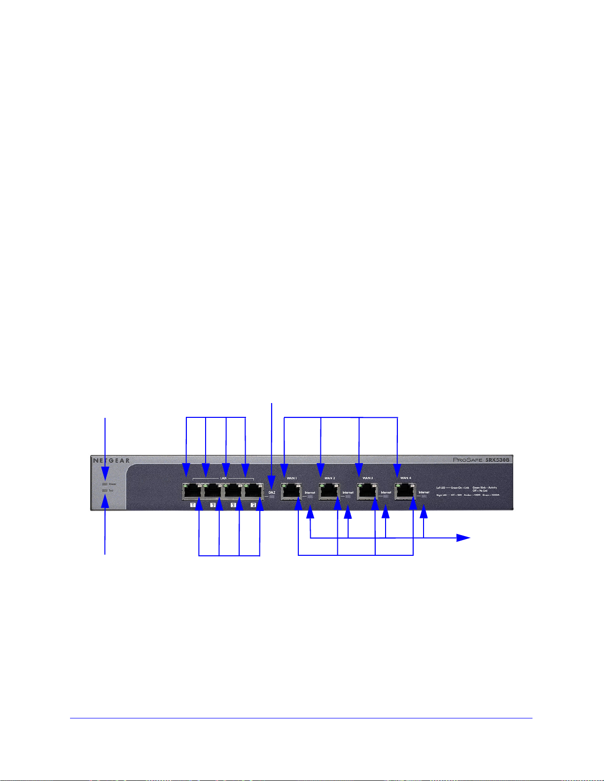
Power LED
Test LED
Left LAN LEDs
Right LAN LEDs
DMZ LED
Left WAN LEDs
Right WAN LEDs
LEDs
Internet
Hardware Features
• Front Panel
• Rear Panel
• Bottom Panel with Product Label
The front panel ports and LEDs, rear panel ports, and bottom label of the VPN firewall are
d
escribed in the following sections.
Front Panel
Viewed from left to right, the VPN firewall front panel contains the following ports (see the
following figure).
AN Ethernet ports. Four switched N-way automatic speed negotiating, Auto MDI/MDIX,
• L
Gigabit Ethernet ports with RJ-45 connectors
• W
AN Ethernet ports. Four independent N-way automatic speed negotiating, Auto
MDI/MDIX, Gigabit Ethernet ports with RJ-45 connectors
The front panel also contains three groups of
including Power and Test LEDs, LAN LEDs, and WAN LEDs, all of which are explained in the
following table.
Figure 1.
status indicator light-emitting diodes (LEDs),
Introduction
17
Page 18

ProSafe Gigabit Quad WAN SSL VPN Firewall SRX5308
Table 1. LED descriptions
LED Activity Description
Power On (green) Power is supplied to the VPN firewall.
Off Power is not supplied to the VPN firewall.
Test On (amber) during
startup.
On (amber) during
any other time
Blinking (amber) The VPN firewall is writing to flash memory (during upgrading or resetting
Off The system has booted successfully.
LAN Ports
Left LED On (green) The LAN port has detected a link with a connected Ethernet device.
Blinking (green) The LAN port receives or transmits data.
Off The LAN port has no link.
Right LED On (green) The LAN port operates at 1000 Mbps.
On (amber) The LAN port operates at 100 Mbps.
Off The LAN port operates at 10 Mbps.
DMZ LED On (green) Port 4 operates as a dedicated hardware DMZ port.
Off Port 4 operates as a normal LAN port.
T e st mode: The VPN firewall is initializing. After approximately 2 minutes,
when the VPN firewall has completed its initialization, the Test LED goes
off.
The initialization has failed, or a hardware failure has occurred.
to defaults).
WAN Ports
Left LED On (green) The WAN port has a valid connection with a device that provides an
Internet connection.
Blinking (green) The WAN port receives or transmits data.
Off The WAN port has no physical link, that is, no Ethernet cable is plugged
into the VPN firewall.
Right LED On (green) The WAN port operates at 1000 Mbps.
On (amber) The WAN port operates at 100 Mbps.
Off The WAN port operates at 10 Mbps.
Internet LED On (green) The WAN port has a valid Internet connection.
Off The WAN port is either not enabled or has no link to the Internet.
Introduction
18
Page 19
ProSafe Gigabit Quad WAN SSL VPN Firewall SRX5308
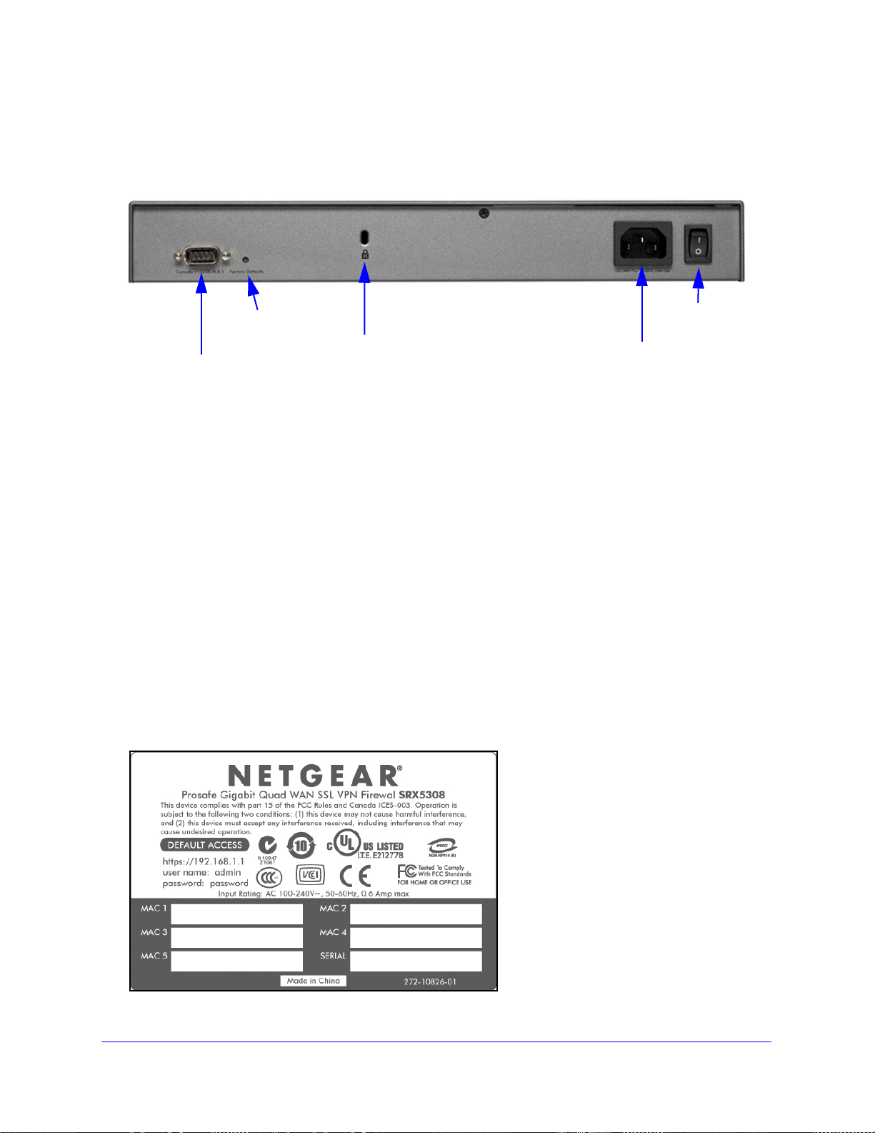
Security lock
receptacle
Console port
Factory Defaults
AC power
receptacle
Power
switch
Reset button
Rear Panel
The rear panel of the VPN firewall includes a console port, a Factory Default s Reset button, a
cable lock receptacle, an AC power connection, and a power switch.
Figure 2.
Viewed from left to right, the rear panel contains the following components:
1. Cab
2. Console
3. Factory
4. AC po
5. A power on/of
le security lock receptacle.
port. Port for connecting to an optional console terminal. The port has a DB9 male
connector. The default baud rate is 115200 K. The pinouts are (2) Tx, (3) Rx, (5) and (7)
Gnd. For information about accessing the command-line interface (CLI) using the console
port, see Use the Command-Line Interface on p
Defaults Reset button. Using a sharp object, press and hold this button for about
8 seconds until the front panel Test LED flashes to reset the VPN fi re w al l to factory defa ult
ttings. All configuration settings are lost, and the default password is restored.
se
wer receptacle. Universal AC input (100–240 VAC, 50–60 Hz).
f switch.
age 334.
Bottom Panel with Product Label
The product label on the bottom of the VPN firewall’s enclosure displays factory default
settings, regulatory compliance, and other information.
Figure 3.
Introduction
19
Page 20
ProSafe Gigabit Quad WAN SSL VPN Firewall SRX5308
Choose a Location for the VPN Firewall
The VPN firewall is suitable for use in an office environment where it can be freestanding (on
its runner feet) or mounted into a standard 19-inch equipment rack. Alternatively, you can
rack-mount the VPN firewall in a wiring closet or equipment room.
Consider the following when deciding where to position the VPN firewall:
• The u
• Cabling is away from sources of electrical noise. Th
• W
• Airflow
• The a
• T
nit is accessible, and cables can be connected easily.
ese include lift shafts, microwave
ovens, and air-conditioning units.
ater or moisture cannot enter the case of the unit.
around the unit and through the vents in the side of the case is not restricted.
Provide a minimum of 25 mm or 1-inch clearance.
ir is as free of dust as possible.
emperature operating limits are not likely to be exceeded. Install the unit in a clean,
air-conditioned environment. For information about the recommended operating
temperatures for the VPN firewall, see Appendix A, Default Settings and Technical
Specifications.
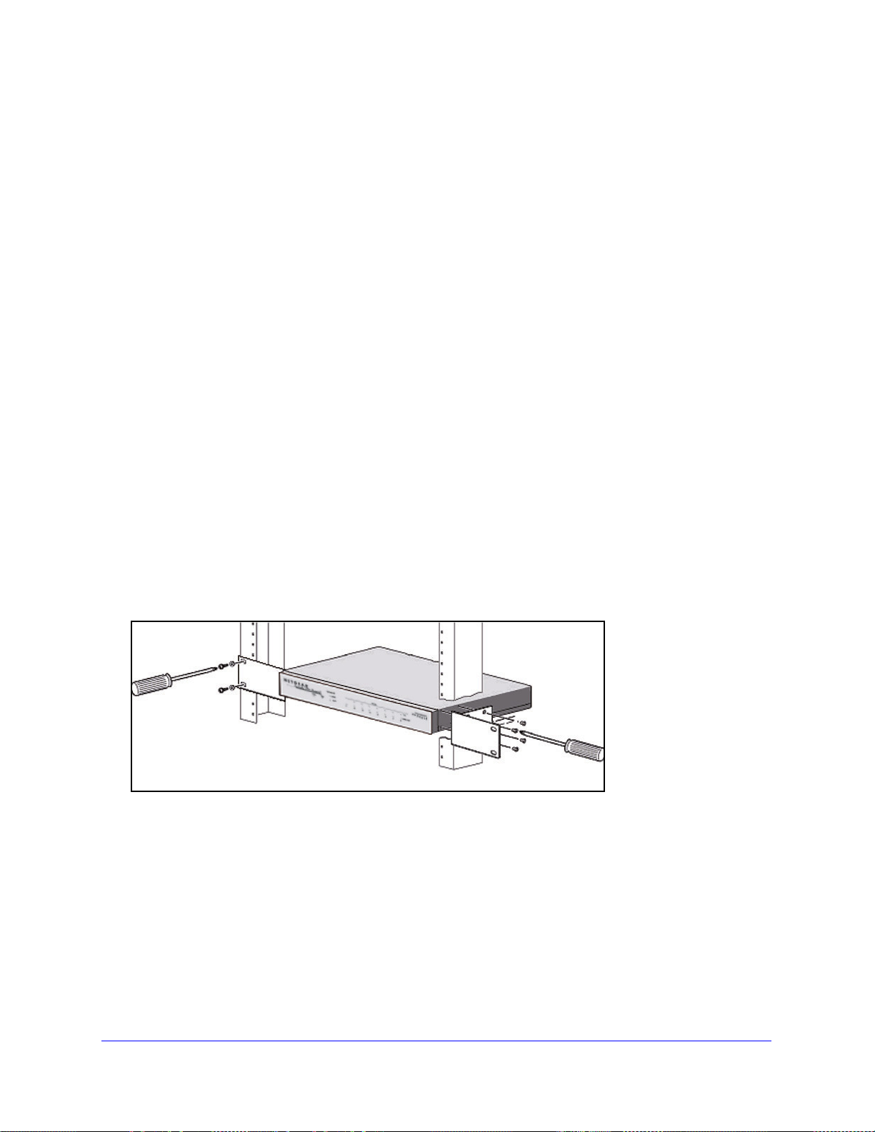
Use the Rack-Mounting Kit
Use the mounting kit for the VPN firewall to install the appliance in a rack. Attach the
mounting brackets using the hardware that is supplied with the mounting kit.
Figure 4.
Before mounting the VPN firewall in a rack, verify that:
ou have the correct screws (supplied with the installation kit).
• Y
• The ra
ck onto which you plan to mount the VPN firewall is suitably located.
Introduction
20
Page 21
ProSafe Gigabit Quad WAN SSL VPN Firewall SRX5308
Log In to the VPN Firewall
Note: To connect the VPN firewall physically to your network, connect the
cables and restart your network according to the instructions in the
ProSafe Gigabit Quad WAN SSL VPN Firewall SRX5308 Installation
Guide. A PDF of this guide is on the NETGEAR support website at
http://kb.netgear.com/app/products/model/a_id/13568.
To configure the VPN firewall, you need to use a web browser such as Microsoft Internet
Explor
cookies, and SSL enabled. (Google Chrome is not supported at this time.)
Although these web browsers are qualified for use with the VPN firewall’s web management
interface, SSL VPN users should choose a browser that supports JavaScript, Java, cookies,
SSL, and ActiveX to take advantage o f the full suite of applications. Note that Java is required
only for the SSL VPN portal, not for the web management interface.
er 7.0 or later, Mozilla Firefox 4.0 or later, or Apple Safari 3.0 or later with JavaScript,
To log in to the VPN firewall:
1. S
tart any of the qualified web browsers.
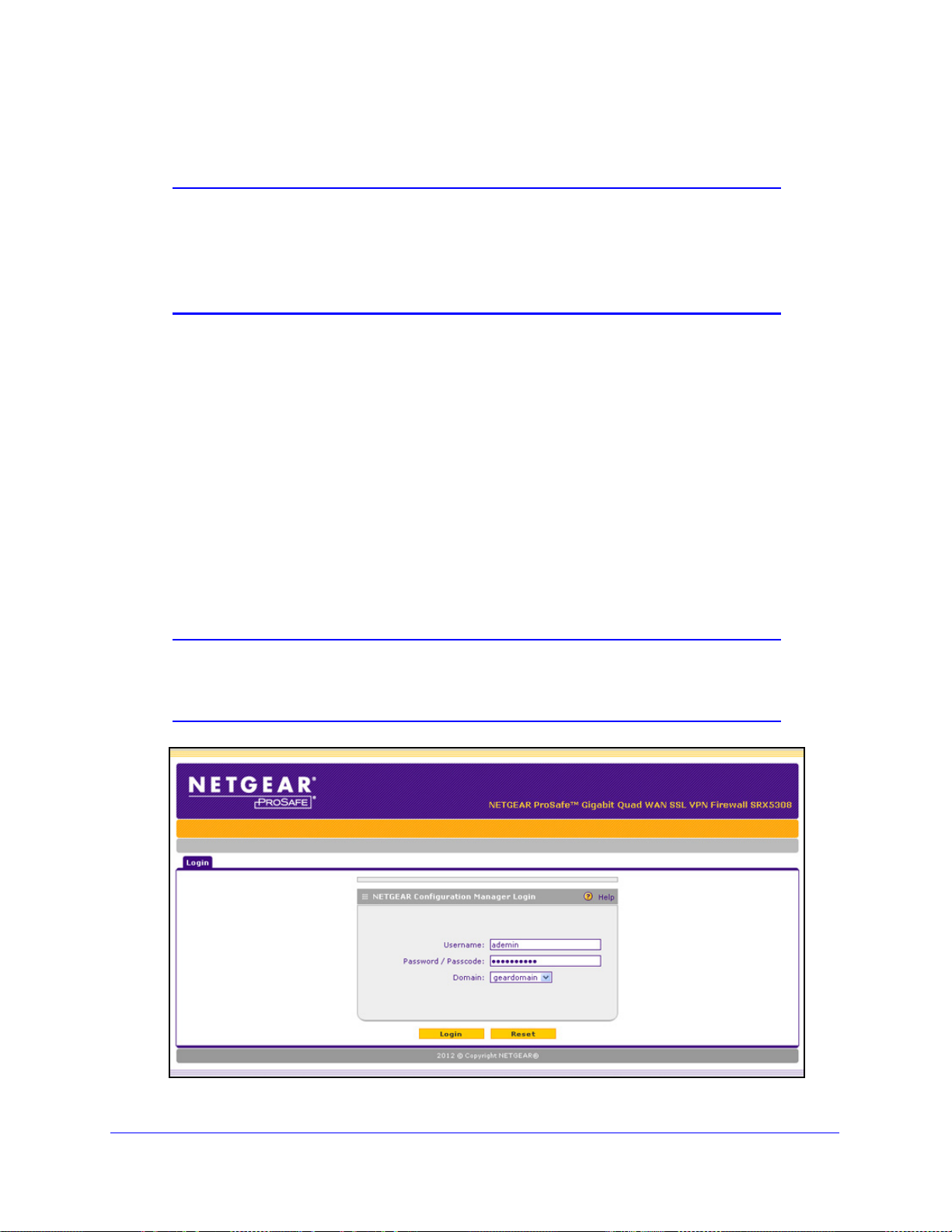
2. In the
address field, enter https://192.168.1.1. The NETGEAR Configuration Manager Login
screen displays in the browser.
Note: The VPN firewall factory default IP address is 192.168.1.1. If you
change the IP address, you need to use the IP address that you
assigned to the VPN firewall to log in to the VPN firewall.
Figure 5.
Introduction
21
Page 22

ProSafe Gigabit Quad WAN SSL VPN Firewall SRX5308
Note: The first time that you remotely connect to the VPN firewall with a
browser through an SSL connection, you might get a warning
message regarding the SSL certificate. Follow the directions of your
browser to accept the SSL certificate.
3. In the User Name field, type admin. Use lowercase letters.
4. In
the Password / Passcode field, type password. Here, too, use lowercase letters.
Note: The VPN firewall user name and password are not the same as any
user name or password you might use to log in to your Internet
connection.
Note: Leave the domain as it is (geardomain).
5. Click Login. The web management interface displays, showing the Router Status screen.
The following figure shows the top part of the Router Status screen. For more information,
see View the System Status o
n page 361.
Note: After 5 minutes of inactivity (the default login time-out), you are
automatically logged out.
Figure 6.
Introduction
22
Page 23
ProSafe Gigabit Quad WAN SSL VPN Firewall SRX5308
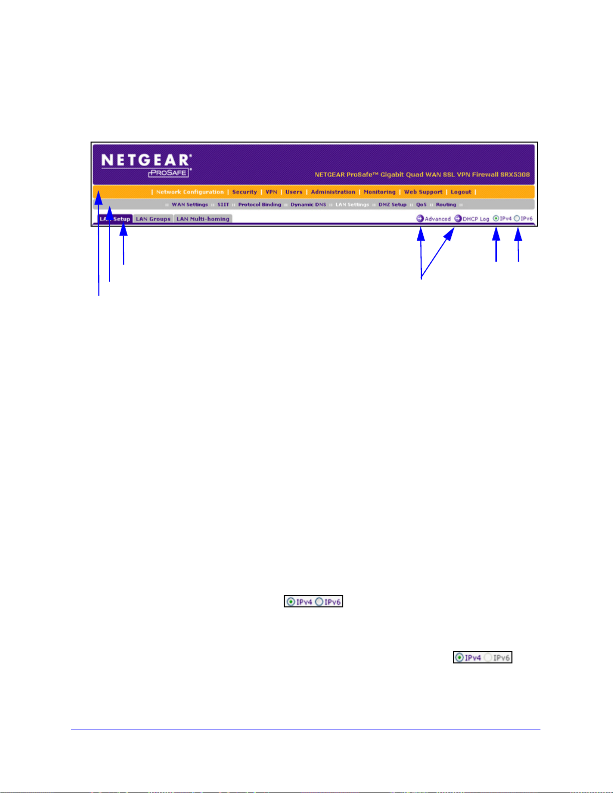
1st level: Main navigation menu link (orange)
2nd level: Configuration menu link (gray)
3rd level: Submenu tab (blue)
Option arrows: Additional screen for submenu item
IP radio buttons
Web Management Interface Menu Layout
The following figure shows the menu at the top the web management interface:
Figure 7.
The web management interface menu consists of the following components:
st level: Main navigation menu links. The main navigation menu in the orange bar
• 1
across the top of the web management interface provides access to all the configuration
functions of the VPN firewall, and remains constant. When you select a main navigation
menu link, the letters are displayed in white against an orange background.
nd level: Configuration menu links. The configuration menu links in the gray bar
• 2
(immediately below the main navigation menu bar) change according to the main
navigation menu link that you select. When you select a configuration menu link, the
letters are displayed in white against a gray background.
• 3
rd level: Submenu tabs. Each configuration menu item has one or more submenu tabs
that are listed below the gray menu bar. When you select a submenu tab, the text is
displayed in white against a blue background.
• Option arrows. If there
are additional screens for the submenu item, links to the screens
display on the right side in blue letters against a white background, preceded by a white
arrow in a blue circle.
• I
P radio buttons. The IPv4 and IPv6 radio buttons let you select the IP version for the
feature to be configured onscreen. There are four options:
- Both
buttons are operational. You can configure the feature onscreen
for IPv4 functionality or for IPv6 functionality
. After you have correctly configured the
feature for both IP versions, the feature can function with both IP versions
simultaneously.
- T
he IPv4 button is operational but the IPv6 button is disabled. You
can configure the feature onscreen for IPv4 functionality only.
Introduction
23
Page 24
ProSafe Gigabit Quad WAN SSL VPN Firewall SRX5308
- The IPv6 button is operational but the IPv4 button is disabled. You
can configure the feature onscreen for IPv6 functionality only.
- Both buttons
are disabled. IP functionality does not apply.
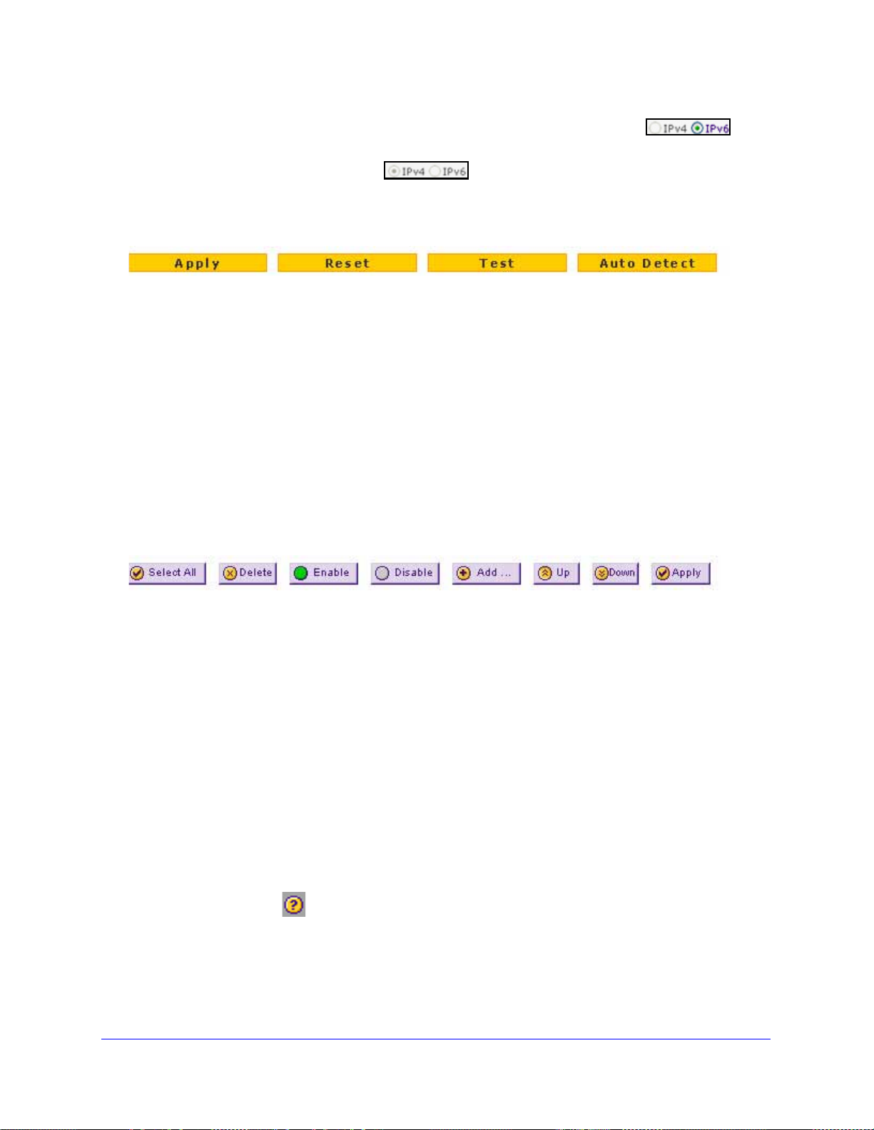
The bottom of each screen provides action buttons. The nature of the screen determines
which action b
Figure 8.
uttons are shown. The following figure shows an example:
Any of the following action buttons might display onscreen (this list might not be complete):
• Apply. Save
• Reset. Reset the
st. Test the configuration.
• Te
• Auto Detect.
and apply the configuration.
configuration to the previously saved configuration.
Enable the VPN firewall to detect the configuration automatically and
suggest values for the configuration.
• Cancel.
When a screen includes a table, table buttons display to
Cancel the operation.
let you configure the table entries.
The nature of the screen determines which table buttons are shown. The following figure
shows an example:
Figure 9.
Any of the following table buttons might display onscreen:
• Select All.
• Delete. Delete th
• Enable.
• Disable.
Select all entries in the table.
e selected entry or entries from the table.
Enable the selected entry or entries in the table.
Disable the selected entry or entries in the table.
• Add. Add a
• Edit. Edit the selected e
• Up. Mo
• Down.
• Apply. Apply the
n entry to the table.
ntry.
ve the selected entry up in the table.
Move the selected entry down in the table.
selected entry.
Almost all screens and sections of screens have an a
help screen, click the (question mark) icon.
Introduction
24
ccompanying help screen. To open the
Page 25

ProSafe Gigabit Quad WAN SSL VPN Firewall SRX5308
Requirements for Entering IP Addresses
To connect to the VPN firewall, your computer needs to be configured to obtain an IP address
automatically from the VPN firewall, either an IPv4 address through DHCP or an IPv6
address through DHCPv6, or both.
IPv4
The fourth octet of an IP address needs to be between 0 and 255 (both inclusive). This
requirement applies to any IP address that you enter on a screen of the web management
interface.
IPv6
IPv6 addresses are denoted by eight groups of hexadecimal quartets that are separated by
colons. Any four-digit group of zeroes within an IPv6 address can b e reduced to a single zero
or altogether omitted.
The following errors invalidate an IPv6 address:
• More t
• More t
• More t
han eight groups of hexadecimal quartets
han four hexadecimal characters in a quartet
han two colons in a row
Introduction
25
Page 26

2. IPv4 and IPv6 Internet and WAN Settings
This chapter explains how to configure the IPv4 and IPv6 Internet and WAN settings. The
chapter contains the following sections:
• Internet and WAN Configuration Tasks
• Configure the IPv4 Internet Connection and WAN Settings
• Configure the IPv6 Internet Connection and WAN Settings
• Configure Advanced WAN Options and Other Tasks
• Configure WAN QoS Profiles
• Additional WAN-Related Configuration Tasks
• What to Do Next
Internet and WAN Configuration Tasks
2
• Tasks to Set Up IPv4 Internet Connections to Your ISPs
• Tasks to Set Up an IPv6 Internet Connection to Your ISPs
Typically, the VPN firewall is installed as a network gateway to function as a combined LAN
switch and firewall to protect the network from incoming threats and provide secure
connections. To complement the firewall protection, NETGEAR advises that you use a
gateway security appliance such as a NETGEAR ProSecure STM appliance.
The tasks that are required to complete the Internet connection of your VPN firewall depend
on whether you use an IPv4 connection, an IPv6 connection, or both to your Internet service
provider (ISP).
Note: The VPN firewall supports simultaneous IPv4 and IPv6 connections.
26
Page 27

ProSafe Gigabit Quad WAN SSL VPN Firewall SRX5308
Tasks to Set Up IPv4 Internet Connections to Your ISPs
Complete these tasks:
1. Confi
2. Con
3. (Optio
4. (Optio
5. (Optio
6. (Optio
gure the IPv4 routing mode. Select either NAT or classical routing: see
Configure the IPv4 WAN Mode on
figure the IPv4 Internet connections to your ISPs. Connect to one or more ISPs by
configuring up to four WAN interfaces: See one of the following sections:
• Let the VPN Firewall Automatically Detect and Configure a
on page 30
• Manually Configure an IPv4 Internet Connection o
As an option, you can program the WAN traffic meter: See Configure and Enable the
WAN Traffic Meter on p
nal) Configure either load balancing or auto-rollover. Select load balancing or
auto-rollover and a failure detection method: See Configure Load Balancing or
Auto-Rollover on p
(single) WAN mode. If you configure load balancing, yo
nal) Configure secondary WAN addresses on the WAN interfaces. Configure
aliases for each WAN interface: See Configure Secondary WAN Addresses o
nal) Configure Dynamic DNS on the WAN interfaces. If required, configure your
fully qualified domain names: See Configure Dynamic DNS on p
nal) Configure the WAN options. If required, change the factory default MTU size,
port speed, and MAC address of the VPN firewall: See Configure Advanced WAN Options
and Other Tasks on p
change the settings.
age 347.
age 39. By default, the WAN interfaces are configured for primary
age 67. These are advanced features, and you usually do not need to
page 28.
n IPv4 Internet Connection
n page 33
u can also configure protocol binding.
n page 46.
age 48.
Tasks to Set Up an IPv6 Internet Connection to Your ISPs
Note: You can configure one WAN interface only for IPv6. This restriction
might be lifted in a later release.
Complete these tasks:
1. Confi
2. Con
gure the IPv6 routing mode. Configure the VPN firewall to support both devices
with IPv4 addresses and devices with IPv6 addresses: See Configure the IPv6 Routing
Mode on
a WAN interface: See one of the following sections:
• Use a DHCPv6 Server to Configure an IPv6 Internet Connection on p
• Configure a Static IPv6 Internet Connection o
• Configure a PPPoE IPv6 Internet Connection on p
page 52.
figure the IPv6 Internet connections to your ISPs. Connect to an ISP by configuring
n page 57
age 60
IPv4 and IPv6 Internet and WAN Settings
age 54
27
Page 28

ProSafe Gigabit Quad WAN SSL VPN Firewall SRX5308
3. Configure the IPv6 tunnels. Enable 6to4 tunnels and configure ISATAP tunnels: See
Configure 6to4 Automatic Tunneling on
Tunneling on p
4. (Op
5. (
tional) Configure Stateless IP/ICMP Translation (SIIT). Enable IPv6 d ev ice s th at do
not have permanently assigned IPv4 addresses to communicate with IPv4-only devices:
See Configure Stateless IP/ICMP Translation on p
Optional) Configure the WAN options. If required, change the factory default MTU size,
port speed, and MAC address of the VPN firewall: See Configure Advanced WAN Options
and Other Tasks on p
change the settings.
age 64.
age 67. These are advanced features, and you usually do not need to
page 63 and Configure ISATAP Automatic
age 66.
Configure the IPv4 Internet Connection and WAN Settings
• Configure the IPv4 WAN Mode
• Let the VPN Firewall Automatically Detect and Configure an IPv4 Internet Connection
• Manually Configure an IPv4 Internet Connection
• Configure Load Balancing or Auto-Rollover
• Configure Secondary WAN Addresses
• Configure Dynamic DNS
To set up your VPN firewall for secure IPv4 Internet connections, you need to determine the
IPv4
WAN mode (see the next section) and then configure the IPv4 Internet connection to
your ISP on the WAN port. The web management interface offers two connection
configuration options, discussed in the following sections:
• Let the VPN Firewall Automatically Detect and
page 30
• Manually Configure an IPv4 Internet Connection on p
Configure an IPv4 Internet Connection on
age 33
Configure the IPv4 WAN Mode
By default, IPv4 is supported and functions in NAT mode but can also function in classical
routing mode. IPv4 functions the same way in IPv4-only mode that it does in IPv4 / IPv6
mode. The latter mode adds IPv6 functionality (see Configure the IPv6 Routing Mode on
page 52).
Network Address Translation
Network Address Translation (NAT) allows all computers on your LAN to share a single public
Internet IP address. From the Internet, there is only a single device (the VPN firewall) and a
single IP address. Computers on your LAN can use any private IP address range, and these
IP addresses are not visible from the Internet.
IPv4 and IPv6 Internet and WAN Settings
28
Page 29
ProSafe Gigabit Quad WAN SSL VPN Firewall SRX5308
Note the following about NAT:
• The VPN firewall uses NAT to select the correct computer (on your LAN) to receive any
incoming data.
• I
f you have only a single public Internet IP address, you need to use NAT (the default
setting).
• I
f your ISP has provided you with multiple public IP addresses, you can use one address
as the primary shared address for Internet access by your computers, and you can map
incoming traffic on the other public IP addresses to specific computers on your LAN. This
one-to-one inbound mapping is configured using an inbound firewall rule.
Classical Routing
In classical routing mode, the VPN firewall performs routing, but without NAT. T o gain Internet
access, each computer on your LAN needs to have a valid static Internet IP address.
If your ISP has allocated a number of static IP addresses to yo u, and you have assigned one
of these addresses to each computer, you can choose classical routing. Or you can use
classical routing for routing private IP addresses within a campus environment.
To view the status of the WAN ports, you can view the Router Status screen (see View the
System Status on page 361).
Configure the IPv4 Routing Mode
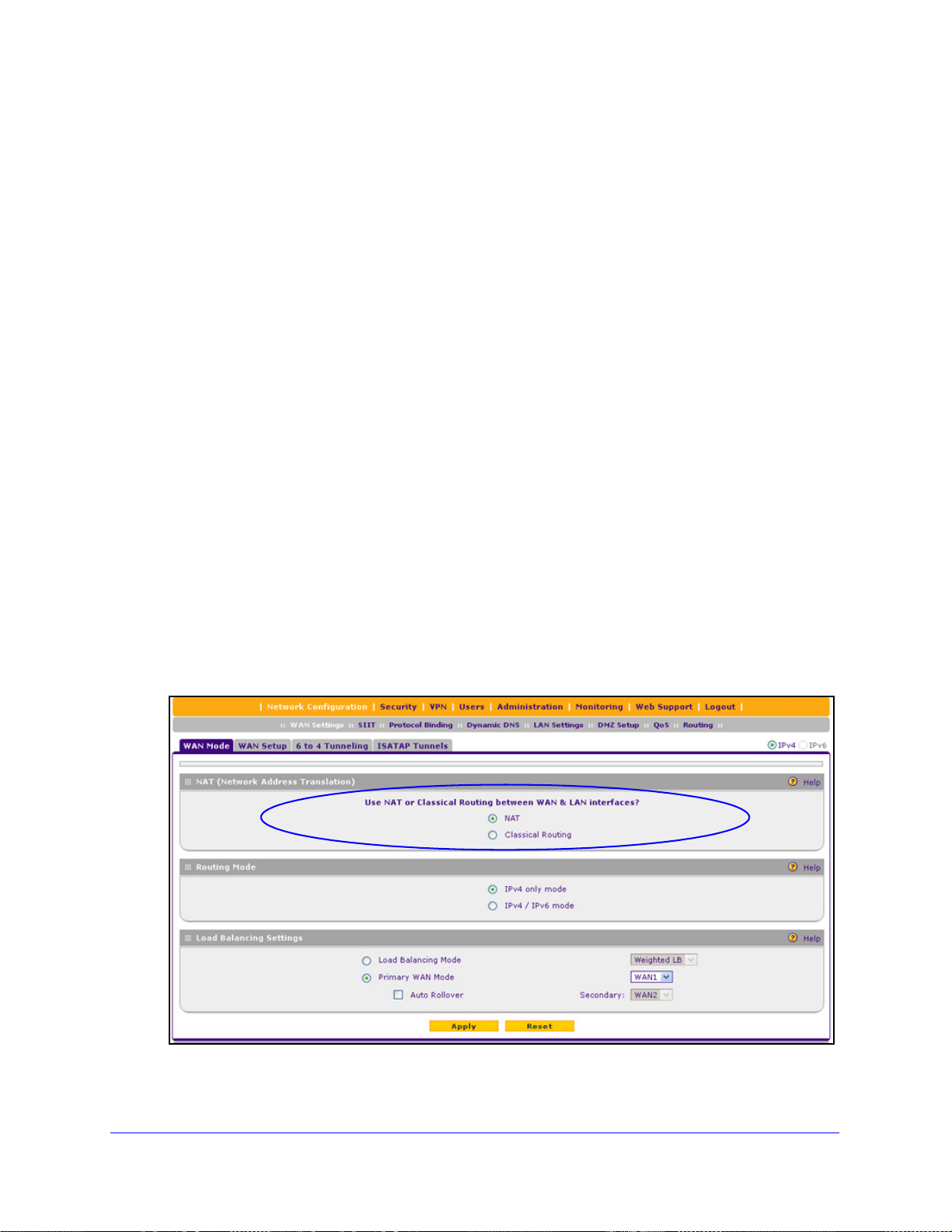
To configure the IPv4 routing mode:
1. Select Network Configu
displays:
ration > WAN Settings > WAN Mode. The WAN Mode screen
Figure 10.
IPv4 and IPv6 Internet and WAN Settings
29
Page 30
ProSafe Gigabit Quad WAN SSL VPN Firewall SRX5308
WARNING:
2. In the NAT (Network Address Translation) section of the screen, select the NAT radio button
or the Classical Routing radio button.
Changing the WAN mode causes all LAN WAN and DMZ WAN
inbound rules to revert to default settings.
3. Click Apply to save your settings. These settings apply to all WAN ports.
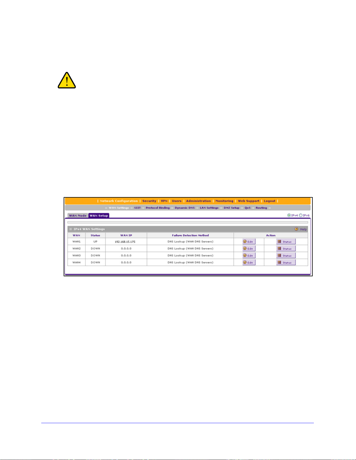
Let the VPN Firewall Automatically Detect and Configure an IPv4 Internet Connection
To automatically configure a WAN port for an IPv4 connection to the Internet:
1. Select Network
screen, the IPv4 radio button is selected by default. The WAN Setup screen displays the
IPv4 settings:
Figure 11.
The IPv4 WAN Settings table displays the following fields:
• WA
• St
• W
• Fa
N. The WAN interface (WAN1, WAN2, WAN3, and WAN4).
atus. The status of the WAN interface (UP or DOWN).
AN IP. The IPv4 address of the WAN interface.
ilure Detection Method. The failure detection method that is active for the WAN
interface. The following methods can be displayed:
- None
Configuration > WAN Settings > WAN Setup. In the upper right of the
- DNS Lookup (W
- DNS Lookup (th
- PING (the configured I
AN DNS Servers)
e configured IP address is displayed)
IPv4 and IPv6 Internet and WAN Settings
P address is displayed)
30
Page 31

ProSafe Gigabit Quad WAN SSL VPN Firewall SRX5308
You can set the failure detection method for each WAN interface on its corresponding
WAN Advanced Options screen (see Configure the Auto-Rollover Mode and Failure
Detection Method o
n page 44).
• Action. Th
e Edit table button provides access to the WAN IPv4 ISP Settings screen
(see Step 2) for the corresponding WAN interface; the Status button provides access
to the Connection Status screen (see Step 4) for the corresponding WAN interface.
2. Click the Edit
table button in the Action column of the WAN interface for which you want to
automatically configure the connection to the Internet. The WAN IPv4 ISP Settings screen
displays. (The following figure shows the WAN2 IPv4 ISP Settings screen as an example.)
Figure 12.
3. Click the Auto Detect button at the bottom of the screen. The autodetect process probes
the WAN port for a range of connection methods and suggests one that your ISP is most
likely to support.
The autodetect process returns one of the following results:
f the autodetect process is successful, a status bar at the top of the screen displays
• I
the results (for example, DHCP service detected).
IPv4 and IPv6 Internet and WAN Settings
31
Page 32

ProSafe Gigabit Quad WAN SSL VPN Firewall SRX5308
• If the autodetect process senses a connection method that requires input from you, it
prompts you for the information. The following table explains the settings that you
might have to enter:
Table 2. IPv4 Internet connection methods
Connection Method Manual Data Input Required
DHCP (Dynamic IP) No manual data input is required.
PPPoE The following fields are required:
• Login
• Password
• Account Name
• Domain Name
PPTP The following fields are required:
• Login
• Password
• Account Name
• Domain Name
• My IP Address
• Server IP Address
Fixed (Static) IP The following fields are required:
• If the
autodetect process does not find a connection, you are prompted either to
check the physical connection between your VPN firewall and the cable, DSL line, or
satellite or wireless Internet dish, or to check your VPN firewall’s MAC address. For
more information, see Configure Advanced WAN Options
page 67 and Troubleshoot the ISP Connection on p
4. V
erify the connection:
a. Select Network
screen displays the IPv4 settings (see Figure 11 on
b. In the Action
want to display the Connection Status pop-up screen. (The following figure shows a
static IP address configuration.)
• IP Address
• IP Subnet Mask
• Gateway IP Address
• Primary DNS Server
• Secondary DNS Server
and Other Tasks on
age 388.
Configuration > WAN Settings > WAN Setup. The WAN Setup
page 30).
column, click the Status button of the WAN interface for which you
IPv4 and IPv6 Internet and WAN Settings
32
Page 33

ProSafe Gigabit Quad WAN SSL VPN Firewall SRX5308
Figure 13.
The Connection Status screen should show a valid IP address and gateway, and you are
connected to the Internet. If the configuration was not successful, skip ahead to Manually
Configure an IPv4 Internet Connection on p
Connection o
n page 388.
age 33, or see Troubleshoot the ISP
Note: For more information about the Connection S t atus screen, see View
the WAN Port Status on page 374.
Manually Configure an IPv4 Internet Connection
Unless your ISP automatically assigns your configuration through a DHCP server, you need
to obtain configuration parameters from your ISP to manually establish an Internet
connection. The required parameters for various connection types are listed in Table 2 on
page 32.
To manually configure the WAN IPv4 ISP settings:
1. Select Network Co
screen, the IPv4 radio button is selected by default. The WAN Setup screen displays the
IPv4 settings:
nfiguration > WAN Settings > WAN Setup. In the upper right of the
Figure 14.
IPv4 and IPv6 Internet and WAN Settings
33
Page 34

ProSafe Gigabit Quad WAN SSL VPN Firewall SRX5308
The IPv4 WAN Settings table displays the following fields:
• WAN. The WAN interface (WAN1, WAN2, WAN3, and WAN4).
• St
• W
• Fa
atus. The status of the WAN interface (UP or DOWN).
AN IP. The IPv4 address of the WAN interface.
ilure Detection Method. The failure detection method that is active for the WAN
interface. The following methods can be displayed:
- None
- DNS Lookup (W
- DNS Lookup (th
- PING (the configured I
AN DNS Servers)
e configured IP address is displayed)
P address is displayed)
You can set the failure detection method for each WAN interface on its corresponding
W
AN Advanced Options screen (see Configure the Auto-Rollover Mode and Failure
Detection Method on p
• Action. The Edit t
(see Step 2) for the corresponding WAN interface; the S
age 44).
able button provides access to the WAN IPv4 ISP Settings screen
tatus button provides access
to the Connection Status screen (see Step 11) for the corresponding WAN interface.
2. Click the Edit
table button in the Action column of the WAN interface for which you want to
manually configure the connection to the Internet. The WAN IPv4 ISP Settings screen
displays (see Figure 12 on p
age 31, which shows the WAN2 IPv4 ISP Settings screen as an
example).
3. Loca
te the ISP Login section on the screen:
Figure 15.
In the ISP Login section, select one of the following options:
• If your ISP requ
ires an initial login to establish an Internet connection, select Yes.
(The default is No.)
• If a login
4. If
you selected Yes, enter the login name in the Login field and the password in the
is not required, select No, and ignore the Login and Password fields.
Password field. This information is provided by your ISP.
5. In
the ISP Type section of the screen, select the type of ISP connection that you use from
the two listed options. By default, Austria (PPTP) is selected, as shown in the following
figure:
IPv4 and IPv6 Internet and WAN Settings
34
Page 35

ProSafe Gigabit Quad WAN SSL VPN Firewall SRX5308
Figure 16.
6. If your connection is PPTP or PPPoE, your ISP requires an initial login. Enter the settings as
explained in the following table:
Table 3. PPTP and PPPoE settings
Setting Description
Austria (PPTP)
Note: For login
and password
information, see
Step 3 and Step 4.
If your ISP is Austria Telecom or any other IS
radio button, and enter the following settings:
Account Name The account name is also known as the host name or system name.
Enter the valid account name for the PPTP connection (usually your
email ID assigned by your ISP). Some ISPs require you to enter
your full email address here.
Domain Name Your domain name or workgroup name assigned by your ISP, or
your ISP’s domain name. You can leave this field blank.
Idle Timeout Select the Keep Connected radio button to keep the connection
always on. To log out after the connection is idle for a period, select
the Idle Timeout radio button and, in the Idle T imeout field, enter the
number of minutes to wait before disconnecting. This is useful if your
ISP charges you based on the period that you have logged in.
My IP Address The IP address assigned by the ISP to make the connection with the
ISP server.
Server IP
Address
The IP address of the PPTP server.
P that uses PPTP for login, select this
IPv4 and IPv6 Internet and WAN Settings
35
Page 36

ProSafe Gigabit Quad WAN SSL VPN Firewall SRX5308
Table 3. PPTP and PPPoE settings (continued)
Setting Description
Other (PPPoE)
Note: For login
d password
an
information, see
Step 3 and Step 4.
If you have installed login software, then your connection type is PPPoE. Select this
radio button, and enter the following settings:
Account Name The valid account name for the PPPoE connection.
Domain Name The name of your ISP’s domain or your domain name if your ISP
has assigned one. You can leave this field blank.
Idle Timeout Select the Keep Connected radio button to keep the connection
always on. To log out after the connection is idle for a period, select
the Idle Timeout radio button and, in the Idle Timeout field, enter the
number of minutes to wait before disconnecting. This is useful if your
ISP charges you based on the period that you have logged in.
Connection
Reset
Select the Connection Reset check box to specify a time when the
PPPoE WAN connection is reset, that is, the connection is
disconnected momentarily and then reestablished. Then specify the
disconnect time and delay.
Disconnect
Time
Delay Specify the period in seconds after which the
Specify the hour and minutes when the connection
should be disconnected.
connection should be reestablished.
7. In the Internet (IP) Address section of the scree n (see the following figure), configure the IP
address settings as explained in the following table. Click the Current IP Address link to
see the currently assigned IP address.
Figure 17.
IPv4 and IPv6 Internet and WAN Settings
36
Page 37

ProSafe Gigabit Quad WAN SSL VPN Firewall SRX5308
Table 4. Internet IP address settings
Setting Description
Get Dynamically
from ISP
Use Static IP
Address
If your ISP has not assigned you a static IP address, select the Get Dynamically from
ISP radio button. The ISP automatically assigns an IP address to the VPN firewall using
DHCP network protocol.
Client Identifier If your ISP requires client identifier information to assign an IP
address using DHCP, select the Client Identifier check box,
and enter the client identifier information in the field.
Vendor Class Identifier If your ISP requires the vendor class identifier information to
assign an IP address using DHCP, select the Vendor Class
Identifier check box.
If your ISP has assigned you a fixed (static or permanent) IP address, select the Use
Static IP Address radio button, and enter the following settings:
IP Address The static IP address assigned to you. This address identifies
the VPN firewall to your ISP.
IP Subnet Mask The subnet mask is usually provided by your ISP.
Gateway IP Address The IP address of the ISP’s gateway is usually provided by
your ISP.
8. In the Domain Name Server (DNS) Servers section of the screen (see the following figure),
specify the DNS settings as explained in the following table.
Figure 18.
Table 5. DNS server settings
Setting Description
Get Automatically
from ISP
Use These DNS
Servers
If your ISP has not assigned any Domain Name Server (DNS) addresses, select the
Get Automatically from ISP radio button.
If your ISP has assigned DNS addresses, select the Use These DNS Servers radio
button. Make sure that you fill in valid DNS server IP addresses in the fields. Incorrect
DNS entries might cause connectivity issues.
Primary DNS Server The IP address of the primary DNS server.
Secondary DNS Server The IP address of the secondary DNS server.
IPv4 and IPv6 Internet and WAN Settings
37
Page 38

ProSafe Gigabit Quad WAN SSL VPN Firewall SRX5308
9. Click Apply to save your changes.
10. Click Te
st to evaluate your entries. The VPN firewall attempts to make a connection
according to the settings that you entered.
erify the connection:
11. V
a. Select Network
Configuration > WAN Settings > WAN Setup. The WAN Setup
screen displays the IPv4 settings (see Figure 14 on p
b. In the Action
column, click the Status button of the WAN interface for which you
want to display the Connection Status pop-up screen. (The following figure shows a
PPPoE configuration; the IP addresses are not related to any other examples in this
manual.)
age 33).
Figure 19.
The Connection Status screen should show a valid IP address and gateway, and you are
connected to the Internet. If the configuration was not successful, see Troubleshoot the
ISP Connection on p
age 388.
Note: If your ISP requires MAC authentication and another MAC address
has been previously registered with your ISP, then you need to enter
that address on the WAN Advanced Options screen for the WAN
interface (see
Configure Advanced WAN Options and Other Tasks
on page 67).
IPv4 and IPv6 Internet and WAN Settings
38
Page 39

ProSafe Gigabit Quad WAN SSL VPN Firewall SRX5308
Configure Load Balancing or Auto-Rollover
The VPN firewall can be configured on a mutually exclusive basis for either auto-rollover (for
increased system reliability) or load balancing (for maximum bandwidth efficiency). If you do
not select load balancing, you need to specify one WAN interface as the primary interface.
• Lo
• Primary WAN mode. The selected WAN interface is made the primary interface. The
• Auto-rollo
ad balancing mode. The VPN firewall distributes the outbound traffic equally among
the WAN interfaces that are functional. You can configure up to four WAN interfaces. The
VPN firewall supports weighted load balancing and round-robin load balancing (see
Configure Load Balancing Mode and Op
Note: Scenarios could arise in which load balancing needs to be bypassed
for certain traffic or applications. If cert ain traffic needs to travel on a
specific WAN interface, configure protocol binding rules for that
WAN interface. The rule should match the desired traffic.
other three interfaces are disabled.
ver mode. The selected WAN interface is defined as the primary link, and
another interface needs to be defined as the rollover link. The remaining two interfaces
are disabled. As long as the primary link is up, all traffic is sent over the primary link.
When the primary link goes down, the rollover link is brought up to send the traff ic. When
the primary link comes back up, traffic automatically rolls back to the original primary link.
If you want to use a redundant ISP link for backup purposes, select the WAN port that
sh
ould function as the primary link for this mode. Ensure that the backup WAN port has
also been configured and that you configure the WAN failure detection method on the
WAN Advanced Options screen to support aut o-rollover (see Configure the Auto-Rollover
Mode and Failure Detection Method on
tional Protocol Binding on page 39).
page 44).
Note: If the VPN firewall functions in IPv4 / IPv6 mode, you cannot
configure load balancing mode nor auto-rollover mode.
Configure Load Balancing Mode and Optional Protocol Binding
To use multiple ISP links simultaneously, configure load balancing. In load balancing mode,
any WAN port carries any outbound protocol unless protocol binding is configured.
When a protocol is bound to a particular WAN port, all outgoing traffic of that protocol is
directed to the bound WAN port. For example, if the HTTPS protocol is bound to the WAN1
port and the FTP protocol is bound to the WAN2 port, then the VPN firewall automatically
routes all outbound HTTPS traffic from the computers on the LAN through th e W AN1 port. All
outbound FTP traffic is routed through the WAN2 port.
IPv4 and IPv6 Internet and WAN Settings
39
Page 40

ProSafe Gigabit Quad WAN SSL VPN Firewall SRX5308
Protocol binding addresses two issues:
• Segregation of traffic between links that are not of the same speed.
High-volume traffic can be routed through the WAN port connected to a high-speed link,
and low-volume
traffic can be routed through the WAN port connected to the low-speed
link.
• Continuity of
source IP address for secure connections.
Some services, particularly HTTPS, cease to resp
changes shortly after a session has been established.
Configure Load Balancing Mode
To configure load balancing mode:
1. Select Network Configurati
on > WAN Settings > WAN Mode. The WAN Mode screen
displays:
ond when a client’s source IP address
Figure 20.
2. In th e Load Balancing Settings sect ion of the screen, configure the following settings:
a. Select the
b. From the co
Load Balancing Mode radio button.
rresponding drop-down list on the right, select one of the following load
balancing methods:
eighted LB. With weighted load balancing, balance weights are calculated
• W
based on WAN link speed and available WAN bandwidth. This is the default
setting and most efficient load balancing algorithm.
• Round-robi
n. With round-robin load balancing, new traffic connections are sent
over a WAN link in a serial method irrespective of bandwidth or link speed. For
example, if the WAN1, W AN2, and W AN3 interfaces are active in round-robin load
balancing mode, an HTTP request could first be sent over the WAN1 interface,
then a new FTP session could start on the WAN2 interface, and then any new
IPv4 and IPv6 Internet and WAN Settings
40
Page 41
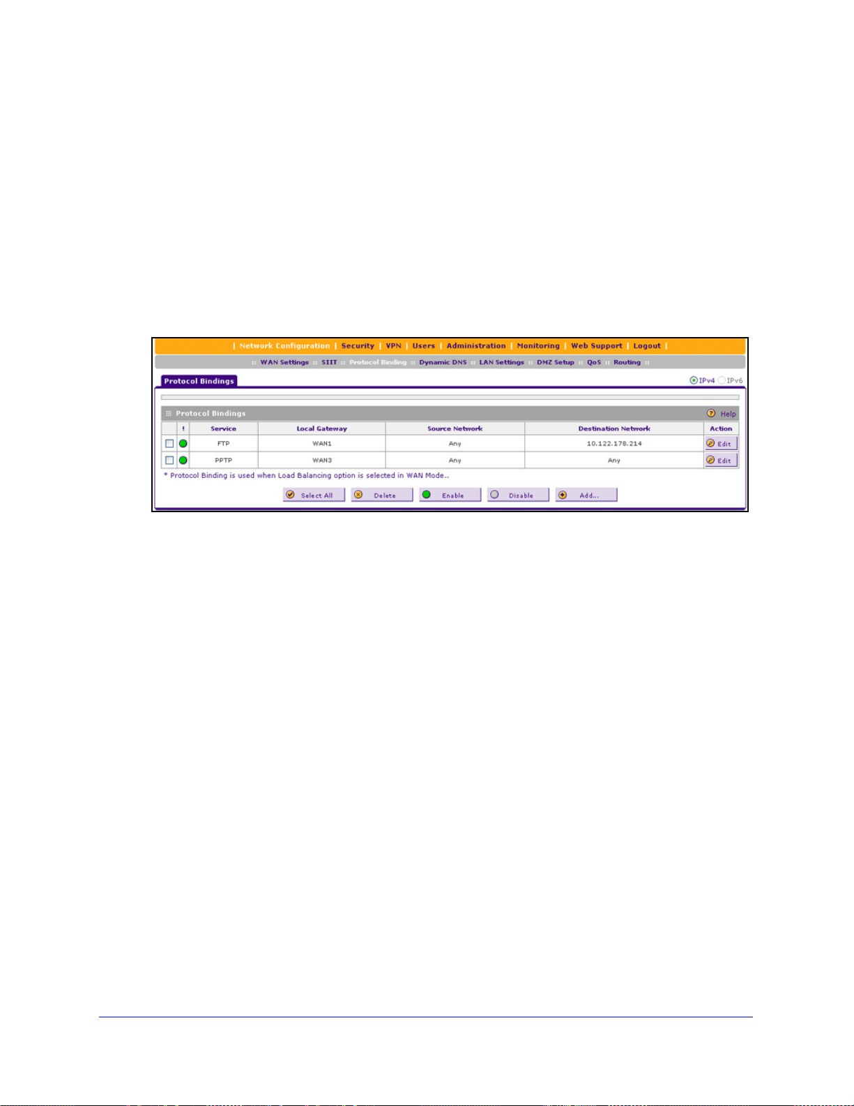
ProSafe Gigabit Quad WAN SSL VPN Firewall SRX5308
connection to the Internet could be made on the WAN3 interface. This
load balancing method ensures that a single WAN interface does not carry a
isproportionate distribution of sessions.
d
3. Click App
ly to save your settings.
Configure Protocol Binding (Optional)
To configure protocol binding and add protocol binding rules:
1. Select Network Configuratio
2. Select th
e Load Balancing radio button. The Protocol Bindings screen displays. (The
n > Protocol Binding.
following figure shows two examples in the Protocol Bindings table.)
Figure 21.
The Protocol Bindings table displays the following fields:
• Check b
tatus icon. Indicates the status of the protocol binding rule:
• S
- Gre
- Gra
• Service.
• Local
ox. Allows you to select the protocol binding rule in the table.
en circle. The protocol binding rule is enabled.
y circle. The protocol binding rule is disabled.
The service or protocol for which the protocol binding rule is set up.
Gateway. The WAN interface to which the service or protocol is bound.
• Source Network. The
protocol binding rule.
• Destinati
on Network. The Internet locations (based on their IP address) or groups
that are covered by the protocol binding rule.
• Action. Th
e Edit table button, which provides access to the Edit Protocol Binding
screen for the corresponding service.
3. Click the Ad
d table button below the Protocol Binding table. The Add Protocol Binding
screen displays:
computers or groups on your network that are affected by the
IPv4 and IPv6 Internet and WAN Settings
41
Page 42

ProSafe Gigabit Quad WAN SSL VPN Firewall SRX5308
Figure 22.
4. Configure the prot ocol binding settings as explained in the following table:
Table 6. Add Protocol Binding screen settings
Setting Description
Service From the drop-down list, select a service or application to be covered by this rule. If the
service or application does not appear in the list, you need to define it using the Services
screen (see Add Customized Services on page 172).
Local Gateway From the drop-down list, select one of the WAN interfaces.
Source Network The source network settings determine which computers on your network are affected by
this rule. Select one of the following options from the drop-down list:
Any All devices on your LAN.
Single address In the Start IP field, enter the IP address to which the rule is applied.
Address Range In the Start IP field and End IP field, enter the IP addresses for the
range to which the rule is applied.
Group If this option is selected, the rule is applied to the selected group.
The group can be a LAN group or an IP (LAN) group.
Note: For information about LAN groups, see Manage IPv4 Groups
and Hosts (IPv4 LAN Groups) on page 91. For information about IP
groups, see Create IP Groups on pa
ge 174.
IPv4 and IPv6 Internet and WAN Settings
42
Page 43

ProSafe Gigabit Quad WAN SSL VPN Firewall SRX5308
Table 6. Add Protocol Binding screen settings (continued)
Setting Description
Destination
Network
The destination network settings determine which Internet locations (based on their IP
address) are covered by the rule. Select one of the following options from the drop-down
list:
Any All Internet IP address.
Single address In the Start IP field, enter the IP address to which the rule is applied.
Address range In the Start IP field and Finish field, enter the IP addresses for the
range to which the rule is applied.
Group If this option is selected, the rule is applied to the selected IP (WAN)
group.
Note: For information about IP groups, see Create IP Groups on
page 174.
5. Click Apply to save your settings. The protocol binding rule is added to the Protocol Binding
table. The rule is automatically enabled, which is indicated by the ! status icon that displays
a green circle.
To edit a protocol binding:
1. On the
table, click the Edit t
Protocol Bindings screen (see Figure 21 on page 41), in the Protocol Bindings
able button to the right of the binding that you want to edit. The Edit
Protocol Bindings screen displays. This screen shows the same fields as the Add Protocol
Bind i ng s screen (see the previous figure).
2. Mo
3. Click App
To enable, disable, or delete one or more protocol bindings:
1. On the
dify the settings as explained in the previous table.
ly to save your settings.
Protocol Bindings screen (see Figure 21 on page 41), select the check box to the
left of the protocol binding that you want to enable, disable, or delete, or click the Select
able button to select all bindings.
All t
2. Click one of the following t
• Enabl
e. Enables the binding or bindings. The ! status icon changes from a gray circle
able buttons:
to a green circle, indicating that the selected binding or bindings are enabled. (By
default, when a binding is added to the table, it is automatically enabled.)
• Disable. Disab
les the binding or bindings. The ! status icon changes from a green
circle to a gray circle, indicating that the selected binding or bindings are disabled.
• Delete. Deletes the b
inding or bindings.
IPv4 and IPv6 Internet and WAN Settings
43
Page 44
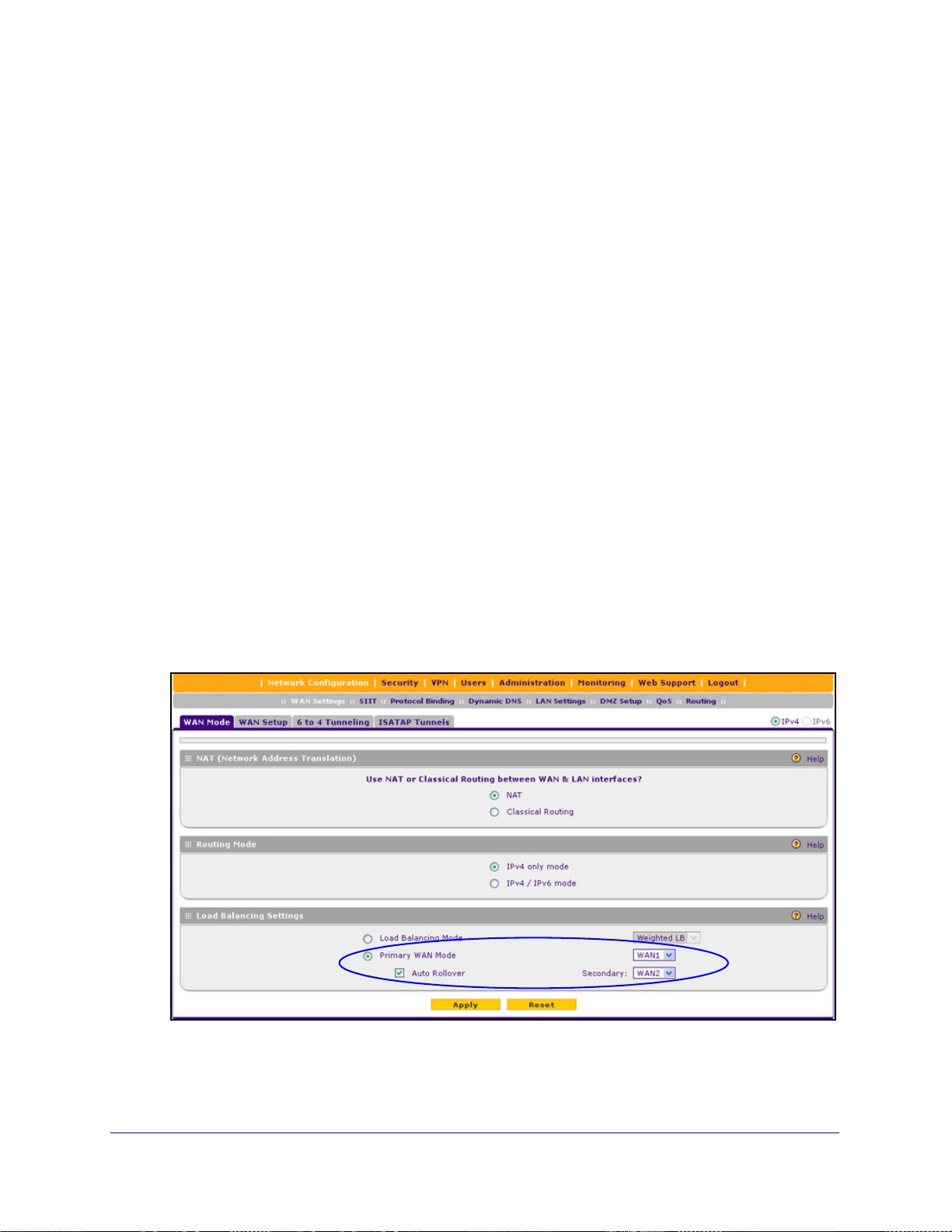
ProSafe Gigabit Quad WAN SSL VPN Firewall SRX5308
Configure the Auto-Rollover Mode and Failure Detection Method
To use a redundant ISP link for backup purposes, ensure that th e backup WAN interface has
already been configured. Then select the WAN interface that will act as the primary link for
this mode, and configure the WAN failure detection method on the WAN Mode screen to
support auto-rollover.
When the VPN firewall is configured in auto-rollover mode, it uses the selected WAN failure
detection method to detect the status of the primary link connection at regular intervals. The
VPN firewall detects link failure in one of the following ways:
• By send
• By send
• None
ing DNS queries to a DNS server
ing a ping request to an IP address
(no failure detection is performed)
From the primary WAN interface, DNS queries or ping requests are sent to the specified IP
addre
ss. If replies are not received, after a specified number of retries, the primary WAN
interface is considered down and a rollover to the backup WAN interface occurs. When the
primary WAN interface comes back up, another rollover occurs from the backup WAN
interface back to the primary WAN interface. The WAN failure detection method that you
select applies only to the primary WAN interface, that is, it monitors the primary link only.
Configure Auto-Rollover Mode
To configure auto-rollover mode:
1. Select Network Configurati
on > WAN Settings > WAN Mode. The WAN Mode screen
displays:
Figure 23.
IPv4 and IPv6 Internet and WAN Settings
44
Page 45

ProSafe Gigabit Quad WAN SSL VPN Firewall SRX5308
2. In the Load Balancing Settings section of the screen, configure the following settings:
a. Select
b. F
the Primary WAN Mode radio button.
rom the corresponding drop-down list on the right, select a WAN interface to
function as the primary WAN interface. The other WAN interfaces become disabled.
c. Select
d. F
the Auto Rollover check box.
rom the corresponding drop-down list on the right, select a WAN interface to
function as the backup WAN interface.
Note: Ensure that the backup WAN interface is configured before enabling
auto-rollover mode.
3. Click Apply to save your settings.
Configure the Failure Detection Method
To configure the failure detection method:
1. Select Network Co
nfiguration > WAN Settings > WAN Setup. In the upper right of the
screen, the IPv4 radio button is selected by default. The WAN Setup screen displays the
IPv4 settings (see Figure 11 on p
2. Click the Edi
t table button in the Action column of the WAN interface that you selected as
age 30).
the primary WAN interface. The WAN IPv4 ISP Settings screen displays (see Figure 12 on
page 31, which shows the WAN2 IPv4 ISP Settings screen as an example).
3. Click the Ad
vanced option arrow in the upper right of the screen. The WAN Advanced
Options screen displays for the WAN interface that you selected. (For an image of the entire
screen, see Figure 43 on p
age 69).
4. Locate t
he Failure Detection Method section on the screen. Enter the settings as explained
in the following table.
IPv4 and IPv6 Internet and WAN Settings
45
Page 46

ProSafe Gigabit Quad WAN SSL VPN Firewall SRX5308
Table 7. Failure detection method settings
Setting Description
Failure Detection
Method
DNS Server The IP address of the DNS server.
dress The IP address of the ping server.
IP Ad
Retry Interval is The retry interval in seconds. The DNS query or ping is sent periodically after every
Failover after The number of failover attempts. The primary WAN interface is considered down after
Select a failure detection method from the drop-down list:
• WAN DNS. DNS queries are sent to the DNS server that is configured in the
Domain Name Server (DNS) Servers section of the WAN ISP screen (see Manually
Configure an IPv4 Internet Connection on
• Cus tom DNS. DNS queries are sent to a DNS server that you need to specify in
the DNS Server fields.
• Ping. Ping
in the IP Address fields. The server should not reject the ping request and should
not consider ping traffic to be abusive.
Note: DNS queries or pings are sent through the WAN interface that
monitored. The retry interval and number of failover attempts determine how quickly
the VPN firewall switches from the primary link to the backup link if the primary link
fails, or when the primary link comes back up, switches back from the backup link to
the primary link.
test period. The default test period is 30 seconds.
the specified number of queries have failed to elicit a reply. The backup interface is
brought up after this situation has occurred. The failover default is 4 failures.
s are sent to a server with a public IP address that you need to specify
page 33).
is being
Note: The default time to roll over after the primary WAN interface fails is
2
minutes. The minimum test period is 30 seconds, and the
minimum number of tests is 2.
5. Click Apply to save your settings.
You can configure the VPN firewall to generate a WAN status log and email this log to a
spe
cified address (see Configure Logging, Alerts, and Event Notifications on page 353).
Configure Secondary WAN Addresses
You can set up a single WAN Ethernet port to be accessed through multiple IPv4 addresses
by adding aliases to the port. An alias is a secondary WAN address. One advantage is, for
example, that you can assign different virtual IP addresses to a web server and an FTP
server, even though both servers use the same physical IP address. You can add several
secondary IP addresses to a single WAN port.
IPv4 and IPv6 Internet and WAN Settings
46
Page 47

ProSafe Gigabit Quad WAN SSL VPN Firewall SRX5308
After you have configured secondary W AN addresses, t hese addresses are displayed o n the
following firewall rule screens:
• In the WAN Destination IP Address drop-down lists of the following inbound firewall rule
screens:
- Add
LAN WAN Inbound Service screen
- Add
• In th
- Add
- Add
DMZ WAN Inbound Service screen
e NAT IP drop-down lists of the following outbound firewall rule screens:
LAN WAN Outbound Service screen
DMZ WAN Outbound Service screen
For more information about firewall rules, see Overview of Rules to Block or Allow Specific
Kinds of Traffic on page 131).
Note: It is important that you ensure that any secondary W AN addresses are
different from the primary WAN, LAN, and DMZ IP addresses that are
already configured on the VPN firewall. However, primary and
secondary WAN addresses can be in the same subnet.
The following is an example of correctly configured IP addresses:
Primary WAN1 IP address: 10.0.0.1 with subnet 255.0.0.0
Secondary WAN1 IP: 30.0.0.1 with subnet 255.0.0.0
Primary WAN2 IP address: 20.0.0.1 with subnet 255.0.0.0
Secondary WAN2 IP: 40.0.0.1 with subnet 255.0.0.0
DMZ IP address: 192.168.10.1 with subnet 255.255.255.0
Primary LAN IP address: 192.168.1.1 with subnet 255.255.255.0
Secondary LAN IP: 192.168.20.1 with subnet 255.255.255.0
To add a secondary WAN address to a WAN port:
1. Select Network Co
nfiguration > WAN Settings > WAN Setup. In the upper right of the
screen, the IPv4 radio button is selected by default. The WAN Setup screen displays the
IPv4 settings (see Figure 11 on p
2. Click the Edit
table button in the Action column of the WAN interface for which you want to
age 30).
add a secondary WAN address. The WAN IPv4 ISP Settings screen displays (see Figure 12
on page 31, which shows the WAN2 IPv4 ISP Settings screen as an example).
3. Click the Sec
ondary Addresses option arrow in the upper right of the screen. The WAN
Secondary Addresses screen displays for the WAN interface that you selected. (The
following figure shows the WAN1 Secondary Addresses screen as an example and includes
one entry in the List of Secondary WAN addresses table.)
IPv4 and IPv6 Internet and WAN Settings
47
Page 48

ProSafe Gigabit Quad WAN SSL VPN Firewall SRX5308
Figure 24.
The List of Secondary WAN addresses table displays the secondary LAN IP addresses
added for the selected WAN interface.
the Add WAN Secondary Addresses section of the screen, enter the following settings:
4. In
• IP Address. Enter th
• Subne
t Mask. Enter the subnet mask for the secondary IP address.
e secondary address that you want to assign to the WAN port.
5. Click the Add t
able button in the rightmost column to add the secondary IP address to the
List of Secondary WAN addresses table.
6. (Opt
ional) Repeat Step 4 and Step 5 for each secondary IP address that you want to add to
the List of Secondary WAN addresses table.
To delete one or more secondary addresses:
1. In the L
ist of Secondary WAN addresses table, select the check box to the left of the
address that you want to delete, or click the Select All table button to select all
addresses.
2. Click the Delete t
able button.
Configure Dynamic DNS
Dynamic DNS (DDNS) is an Internet service that allows devices with varying public IPv4
addresses to be located using Internet domain names. To use DDNS, you need to set up an
account with a DDNS provider such as DynDNS.org, TZO.com, Oray.net, or 3322.org. (Links
to DynDNS, TZO, Oray , and 3322 are provide d for your convenience as option arrows on the
DDNS configuration screens.) The VPN firewall firmware includes software that notifies
DDNS servers of changes in the WAN IP address so that the services running on this
network can be accessed by others on the Internet.
If your network has a permanently assigned IP address, you can register a domain name and
have that name linked with your IP address by public Domain Name Servers (DNS).
However , if your I nternet accoun t uses a dyn amically assig ned IP address, you will not know
in advance what your IP address will be, and the address can change frequently—hence, the
need for a commercial DDNS service, which allows you to register an extension to its
IPv4 and IPv6 Internet and WAN Settings
48
Page 49

ProSafe Gigabit Quad WAN SSL VPN Firewall SRX5308
domain, and restores DNS requests for the resulting fully qualified domain name (FQDN) to
your frequently changing IP address.
After you have configured your account information on the VPN firewall, when your
ISP-assigned IP address changes, your VPN firewall automatically contacts your DDNS
service provider, logs in to your account, and registers your new IP address. Consider the
following:
• For auto-rollover mode, you need a fully qualified domain name (FQDN) to implement
features such as exposed hosts and virtual private networks regardless of whether you
have a fixed or dynamic IP address.
• For load ba
lancing mode, you might still need a fully qualified domain name (FQDN)
either for convenience or if you have a dynamic IP address.
Note: If your ISP assigns a private WAN IP address such as 192.168.x.x
or 10.x.x.x, the DDNS service does not work because private
addresses are not routed on the Internet.
To configure DDNS:
1. Select Network Configuratio
(see the following figure).
The WAN Mode section on the screen reports the currently configured WAN mode (for
xample, Single Port WAN1, Load Balancing, or Auto Rollover). Only those options that
e
match the configured WAN mode are accessible on the screen.
2. Click the submenu t
ab for your DDNS service provider:
• Dynamic DNS for Dyn
• DNS TZO for TZO.com
• DNS Or
ay for Oray.net
• 3322 DDNS for 332
n > Dynamic DNS. The Dynamic DNS screen displays
DNS.org (which is shown in the following figure)
2.org
IPv4 and IPv6 Internet and WAN Settings
49
Page 50
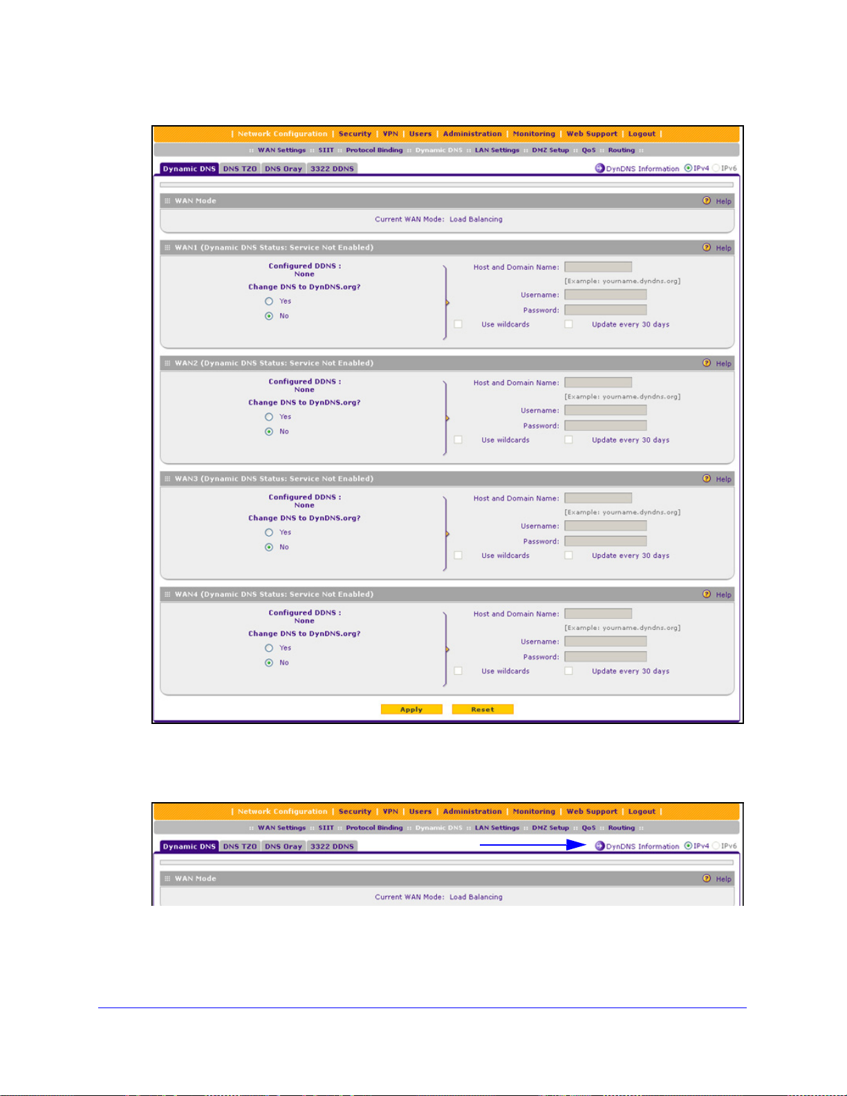
ProSafe Gigabit Quad WAN SSL VPN Firewall SRX5308
Figure 25.
3. Click the Information option arrow in the upper right of a DNS screen for registration
information (for example, DynDNS Information).
Figure 26.
4. Access the website of the DDNS service p rovider, and register for an account (for example,
for DynDNS.org, go to http://www.dyndns.com/).
IPv4 and IPv6 Internet and WAN Settings
50
Page 51

ProSafe Gigabit Quad WAN SSL VPN Firewall SRX5308
5. Configure the DDNS service settings as explained in the following table:
Table 8. DDNS service settings
Setting Description
WAN1 (... Status: ...)
Select the Yes radio button to enable the DDNS service. The fields that display on the screen depend on
the DDNS service provider that you have selected. Enter the following settings:
Host and Domain Name The host and domain name for the DDNS service.
Username or
User Email Address
Password or User Key The password that is used for DDNS server authentication.
Use wildcards If your DDNS provider allows the use of wildcards in resolving your URL, you
Update every 30 days If your WAN IP address does not change often, you might need to force a
WAN2 (... Status: ...)
WAN3 (... Status: ...)
WAN4 (... Status: ...)
See the information for WAN1 about how to enter the settings. You can select different DDNS services for
different WAN interfaces.
6. Click App
ly to save your configuration.
The user name or email address for DDNS server authentication.
can select the Use wildcards check box to activate this feature. For example,
the wildcard feature causes *.yourhost.dyndns.org to be aliased to the same IP
address as yourhost.dyndns.org.
periodic update to the DDNS service to prevent your account from expiring. If
the Update ever y 30 da ys check box displays, select it to enable a periodic
update.
Configure the IPv6 Internet Connection and WAN Settings
• Configure the IPv6 Routing Mode
• Use a DHCPv6 Server to Configure an IPv6 Internet Connection
• Configure a Static IPv6 Internet Connection
• Configure a PPPoE IPv6 Internet Connection
• Configure 6to4 Automatic Tunneling
• Configure ISATAP Automatic Tunneling
• View the Tunnel Status and IPv6 Addresses
• Configure Stateless IP/ICMP Translation
IPv4 and IPv6 Internet and WAN Settings
51
Page 52

ProSafe Gigabit Quad WAN SSL VPN Firewall SRX5308
Note: You can configure only one WAN interface for IPv6. This restriction
might be lifted in a later release. You can configure the other three
WAN interfaces for IPv4.
The nature of your IPv6 network determines how you need to configure the IPv6 Internet
connections:
• Native IPv
IPv6 address and is connected to an IPv6 ISP and if your network consists of IPv6-only
devices. However, because we are in a IPv4-to-IPv6 transition period, native IPv6 is not
yet very common.
• Isola
to an IPv6 ISP, you need to make sure that the IPv6 packets can travel over the IPv4
Internet backbone; you do this by enabling automatic 6to4 tunneling (see Configure 6to4
Automatic Tunneling o
• Mix
After you have configured the IPv6 routing mode (see the next section), you need to
configure one or more WAN interfaces with a global unicast address to enable secure IPv6
Internet connections on your VPN firewall. A global unicast address is a public and routable
IPv6 WAN address that can be statically or dynamically assigned. The web management
interface offers two connection configuration options:
ed network with IPv4 and IPv6 devices. If your network is an IPv4 network that
consists of both IPv4 and IPv6 devices, you need to make sure that the IPv6 p acket s can
travel over the IPv4 intranet; you do this by enabling and configuring ISATAP tunneling
(see Configure ISATAP Automatic Tunneling o
Note: A network can be both an isolated IPv6 network and a mixed
6 network. Your network is a native IPv6 network if the VPN firewall has an
ted IPv6 network. If your network is an isolated IPv6 network that is not connected
n page 63).
n page 64).
network with IPv4 and IPv6 devices.
• Automatic
Configure an IPv6 Internet Connection o
• Man
ual configuration of the network connection (see Configure a Static IPv6 Internet
Connection on p
configuration of the network connection (see Use a DHCPv6 Server to
n page 54)
age 57 or Configure a PPPoE IPv6 Internet Connection on page 60)
Configure the IPv6 Routing Mode
By default the VPN firewall supports IPv4 only. To use IPv6, you need to enable the VPN
firewall to support both devices with IPv4 addresses and devices with IPv6 addresses. The
routing mode does not include an IPv6-only option; however, you still can configure a native
IPv6 network if your ISP supports IPv6.
IPv4 and IPv6 Internet and WAN Settings
52
Page 53

ProSafe Gigabit Quad WAN SSL VPN Firewall SRX5308
These are the options:
• IPv4-only mode. The VPN firewall communicates only with devices that have IPv4
addresses.
• I
Pv4/IPv6 mode. The VPN firewall communicates with both devices that have IPv4
addresses and devices that have IPv6 addresses.
Note: IPv6 always functions in classical routing mode between the WAN
interface and the LAN interfaces; NAT does not apply to IPv6.
Note: When the Load Balancing Mode radio button is selected in the Load
Balancing Settings section of the WAN Mode screen, the IPv4 / IPv6
mode radio button is dimmed, preventing you from selecting it. You
can select the IPv4 / IPv6 mode radio button only when the Primary
WAN Mode radio button is selected.
To configure the IPv6 routing mode:
1. Select Network Configu
ration > WAN Settings > WAN Mode. The WAN Mode screen
displays:
Figure 27.
2. In the Routing Mode section of the screen, select the IPv4 / IPv6 mode radio button. By
default, the IPv4 only mode radio button is selected, and IPv6 is disabled.
IPv4 and IPv6 Internet and WAN Settings
53
Page 54

ProSafe Gigabit Quad WAN SSL VPN Firewall SRX5308
WARNING:
Changing the IP routing mode causes the VPN firewall to reboot.
3. Click Apply to save your changes.
Use a DHCPv6 Server to Configure an IPv6 Internet Connection
The VPN firewall can autoconfigure its ISP settings through a DHCPv6 server by using either
stateless or stateful address autoconfiguration:
tateless address autoconfiguration. The VPN firewall generates its own IP address
• S
by using a combination of locally available information and router advertisements, but
receives DNS server information from a DHCPv6 server.
Router advertisements include a prefix that identifies the subnet that is associated with
AN port. The IP address is formed by combining this prefix and the MAC address of
the W
the WAN port. The IP address is a dynamic address.
As an option for stateless address autoconfiguration, the ISP’s st
can assign a prefix through prefix delegation. The VPN firewall’s own stateless DHCPv6
server can assign this prefix to its IPv6 LAN clients. For more information about prefix
delegation, see Stateless DHCPv6 Server With Prefix Delegation on p
tateful address autoconfiguration. The VPN firewall obtains an interface address,
• S
configuration information such as DNS server information, and other parameters from a
DHCPv6 server. The IP address is a dynamic address.
To automatically configure a WAN interface for an IPv6 connection to the Internet:
1. Select Netwo
the upper right of the screen, select the IPv6 radio button. The WAN Setup screen
2. In
displays the IPv6 settings:
rk Configuration > WAN Settings > WAN Setup.
ateful DHCPv6 server
age 98.
Figure 28.
IPv4 and IPv6 Internet and WAN Settings
54
Page 55
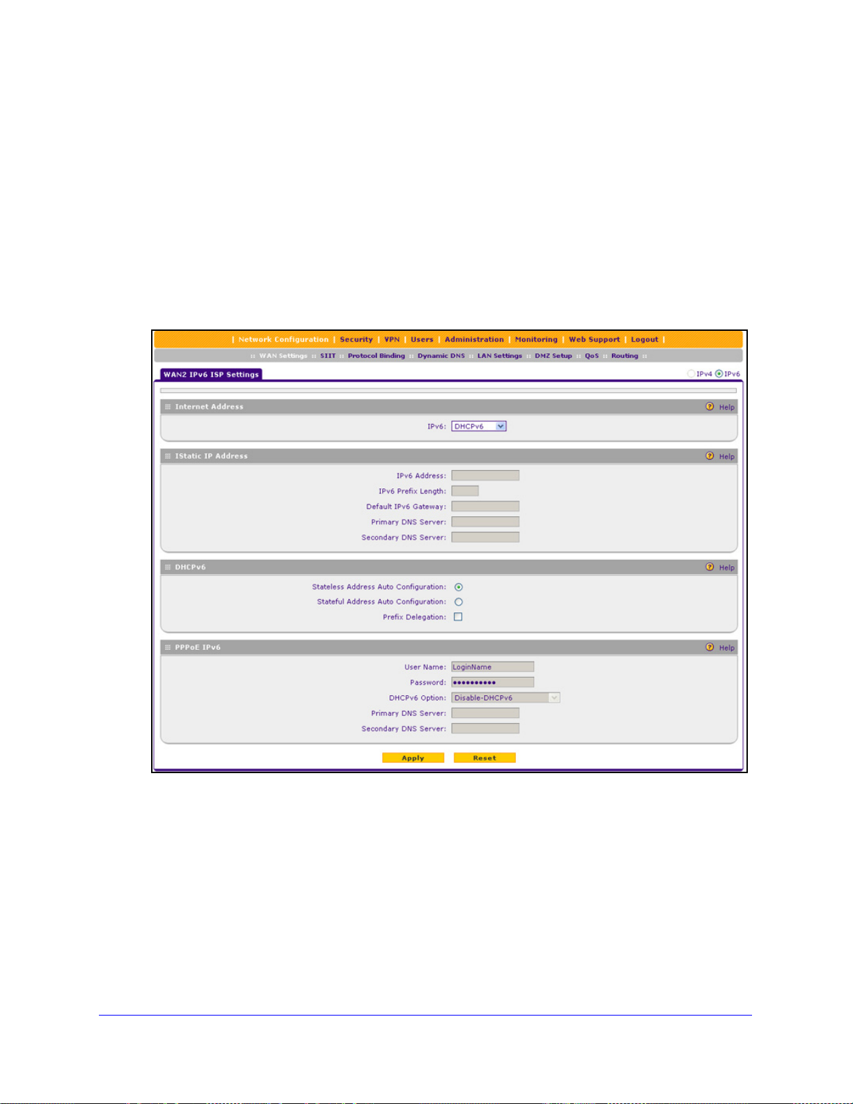
ProSafe Gigabit Quad WAN SSL VPN Firewall SRX5308
The IPv6 WAN Settings table displays the following fields:
• WAN. The WAN interface (WAN1, WAN2, WAN3, and WAN4).
• S
tatus. The status of the WAN interface (UP or DOWN).
• W
AN IP. The IPv6 address of the WAN interface.
• Action. Th
e Edit table button provides access to the WAN IPv6 ISP Settings screen
(see Step 3) for the corresponding WAN interface; the Status button provides access
to the Connection Status screen (see Step 8) for the corresponding WAN interface.
3. Click the Edit
table button in the Action column of the WAN interface for which you want to
automatically configure the connection to the Internet. The WAN IPv6 ISP Settings screen
displays. (The following figure shows the WAN2 IPv6 ISP Settings screen as an example.)
Figure 29.
4. In the Internet Address section of the screen, from the IPv6 drop-down list, select DHCPv6.
5. In the DHCPv6 section of the screen
• S
tateless Address Auto Configuration
• S
tateful Address Auto Configuration
IPv4 and IPv6 Internet and WAN Settings
, select one of the following radio buttons:
55
Page 56

ProSafe Gigabit Quad WAN SSL VPN Firewall SRX5308
6. As an opt ional step: If you ha ve selected the Stateless Address Auto Configuration radio
button, you can select the Prefix Delegation check box:
• Pre
fix delegation check box is selected. A prefix is assigned by the ISP’s stateful
DHCPv6 server through prefix delegation, for example, 2001:db8:: /64. The VPN
firewall’s own stateless DHCPv6 server can assign this prefix to its IPv6 LAN clients.
For more information about prefix delegation, see St atele ss DHCPv6 Server With
Prefix Delegation on p
age 98.
• Pre
fix delegation check box is cleared. Prefix delegation is disabled. This is the
default setting.
7. Click Apply to
erify the connection:
8. V
a. Select Network
b. In
the upper right of the screen, select the IPv6 radio button. The WAN Setup screen
displays the IPv6 settings (see Figure 28 on
c. In the Action
want to display the Connection Status pop-up screen. (The following figure shows a
dynamic IP address configuration.)
save your changes.
Configuration > WAN Settings > WAN Setup.
page 54).
column, click the Status button of the WAN interface for which you
Figure 30.
The Connection Status screen should show a valid IP address and gateway, and you are
connected to the Internet. If the configuration was not successful, see Troubleshoot the
ISP Connection on p
age 388.
Note: For more information about the Connection Status screen, se e View
the WAN Port Status on page 374.
IPv4 and IPv6 Internet and WAN Settings
56
Page 57

ProSafe Gigabit Quad WAN SSL VPN Firewall SRX5308
Configure a Static IPv6 Internet Connection
To configure a static IPv6 or PPPoE IPv6 Internet connection, you need to enter the IPv6
address information that you should have received from your ISP.
To configure static IPv6 ISP settings for a WAN interface:
1. Select Network Configuratio
2. In the upper
right of the screen, select the IPv6 radio button. The WAN Setup screen
n > WAN Settings > WAN Setup.
displays the IPv6 settings:
Figure 31.
The IPv6 WAN Settings table displays the following fields:
• WA
• S
• W
• Action. Th
N. The WAN interface (WAN1, WAN2, WAN3, and WAN4).
tatus. The status of the WAN interface (UP or DOWN).
AN IP. The IPv6 address of the WAN interface.
e Edit table button provides access to the WAN IPv6 ISP Settings screen
(see Step 3) for the corresponding WAN interface; the Status button provides access
to the Connection Status screen (see Step 7) for the corresponding WAN interface.
3. Click the Edit
table button in the Action column of the WAN interface for which you want to
automatically configure the connection to the Internet. The WAN IPv6 ISP Settings screen
displays. (The following figure shows the WAN2 IPv6 ISP Settings screen as an example.)
IPv4 and IPv6 Internet and WAN Settings
57
Page 58

ProSafe Gigabit Quad WAN SSL VPN Firewall SRX5308
Figure 32.
4. In the Internet Add ress section of the screen, from the IPv6 drop-down list, select Static
IPv6.
5. In
the Static IP Address section of the screen, enter the settings as explained in the following
table. You should have received static IPv6 address information from your IPv6 ISP:
Table 9. WAN ISP IPv6 Settings screen settings for a static IPv6 address
Setting Description
IPv6 Address The IP address that your ISP assigned to you. Enter the address in one of the
following formats (all four examples specify the same IPv6 address):
• 2001:db8:0000:0000:020f:24ff:febf:dbcb
• 2001:db8:0:0:20f:24f
• 2001:db8::20f:24ff:febf:dbcb
• 2001:db8:0:0:20f:24f
IPv6 Prefix Length The prefix length that your ISP assign
Default IPv6 Gateway The IPv6 IP address of the ISP’s default IPv6 gateway.
Primary DNS Server The IPv6 IP address of the ISP’s primary DNS server.
Secondary DNS Server The IPv6 IP address of the ISP’s secondary DNS server.
f:febf:dbcb
f:128.141.49.32
ed to you, typically 64.
IPv4 and IPv6 Internet and WAN Settings
58
Page 59

ProSafe Gigabit Quad WAN SSL VPN Firewall SRX5308
6. Click Apply to save your changes.
erify the connection:
7. V
a. Select Ne
b. In the upper
twork Configuration > WAN Settings > WAN Setup.
right of the screen, select the IPv6 radio button. The WAN Setup screen
displays the IPv6 settings (see Figure 31 on p
n the Action column, click the Status button of the WAN interface for which you
c. I
want to display the Connection Status pop-up screen. (The following figure shows a
static IP address configuration; the IP addresses are not related to any other
examples in this manual.)
age 57).
Figure 33.
The Connection Status screen should show a valid IP address and gateway, and you are
connected to the Internet. If the configuration was not successful, see Troubleshoot the
ISP Connection on
page 388.
Note: For more information about the Connection S t atus screen, see View
the WAN Port Status on page 374.
Note: If your ISP requires MAC authentication and another MAC address
has been previously registered with your ISP, then you need to enter
that address on the WAN Advanced Options screen for the
corresponding WAN interface (see
Configure Advanced WAN
Options and Other Tasks on page 67).
IPv4 and IPv6 Internet and WAN Settings
59
Page 60

ProSafe Gigabit Quad WAN SSL VPN Firewall SRX5308
Configure a PPPoE IPv6 Internet Connection
To configure a PPPoE IPv6 Internet connection, you need to enter the PPPoE IPv6
information that you should have received from your ISP.
To configure PPPoE IPv6 ISP settings for a WAN interface:
1. Select Netwo
the upper right of the screen, select the IPv6 radio button. The WAN Setup screen
2. In
rk Configuration > WAN Settings > WAN Setup.
displays the IPv6 settings:
Figure 34.
The IPv6 WAN Settings table displays the following fields:
• WA
• St
• W
• Action. The Edit t
N. The WAN interface (WAN1, WAN2, WAN3, and WAN4).
atus. The status of the WAN interface (UP or DOWN).
AN IP. The IPv6 address of the WAN interface.
able button provides access to the WAN IPv6 ISP Settings screen
(see Step 3) for the corresponding WAN interface; the S
tatus button provides access
to the Connection Status screen (see Step 7) for the corresponding WAN interface.
3. Click the Edit
table button in the Action column of the WAN interface for which you want to
automatically configure the connection to the Internet. The WAN IPv6 ISP Settings screen
displays. (The following figure shows the WAN2 IPv6 ISP Settings screen as an example.)
IPv4 and IPv6 Internet and WAN Settings
60
Page 61

ProSafe Gigabit Quad WAN SSL VPN Firewall SRX5308
Figure 35.
4. In the Internet Address section of the screen, from the IPv6 drop-down list, select PPPoE.
5. In the PPPoE IPv6 section of
the screen, enter the settings as explained in the following
table. You should have received PPPoE IPv6 information from your ISP:
Table 10. WAN IPv6 ISP Settings screen settings for a PPPoE IPv6 connection
Setting Description
User Name The PPPoE user name that is provided by your ISP.
Password The PPPoE password that is provided by your ISP.
IPv4 and IPv6 Internet and WAN Settings
61
Page 62

ProSafe Gigabit Quad WAN SSL VPN Firewall SRX5308
Table 10. WAN IPv6 ISP Settings screen sett ings for a PPPoE IPv6 connection (continued)
Setting Description
DHCPv6 Option From the DHCPv6 Option drop-down list, select one of the following DHCPv6
server options, as directed by your ISP:
• Disable
the Primary DNS Server and Secondary DNS Server fields in order to recei ve
an IP address from the ISP.
• DHCPv6
using a combination of locally available information and router advertisements,
but receives DNS server information from the ISP’s DHCPv6 server. Router
advertisements include a prefix that identifies the subnet that is associated with
the WAN port. The IP address is formed by combining this prefix and the MAC
address of the WAN port. The IP address is a dynamic address.
• DHCPv6
configuration information such as DNS server information, and other
parameters from the ISP’s DHCPv6 server. The IP address is a dynamic
address.
• DHCPv6
DHCPv6 server through prefix delegation, for example, 2001:db8:: /64. The
VPN firewall’s own stateless DHCPv6 server can assign this prefix to its IPv6
LAN clients. For more information about prefix delegation, see Stateless
DHCPv6 Server With Prefix Delegation on
-DHCPv6. DHCPv6 is disabled. You need to specify the DNS servers in
StatelessMode. The VPN firewall generates its own IP address by
StatefulMode. The VPN firewall obtains an interface address,
Prefix Delegation. The VPN firewall obtains a prefix from the ISP’s
page 98.
Primary DNS Server If you have selected the Disable-DHCPv6 from the DHCPv6 Options drop-down
list, the IPv6 IP address of the ISP’s primary DNS server.
Secondary DNS Server If you have selected the Disable-DHCPv6 from the DHCPv6 Options drop-down
list, the IPv6 IP address of the ISP’s secondary DNS server.
6. Click Apply to save your changes.
erify the connection:
7. V
a. Select Network
b. In
the upper right of the screen, select the IPv6 radio button. The WAN Setup screen
displays the IPv6 settings (see Figure 34 on
c. In the Action
Configuration > WAN Settings > WAN Setup.
page 60).
column, click the Status button of the WAN interface for which you
want to display the Connection Status pop-up screen. (See Figure 33 on p
which shows a static IP address configuration; the screen for
The Connection Status screen should show a valid IP
address and gateway, and you are
PPPoE is very similar.)
connected to the Internet. If the configuration was not successful, see Troubleshoot the
ISP Connection on p
age 388.
Note: For more information about the Connection Status screen, se e View
the WAN Port Status on page 374.
age 59,
IPv4 and IPv6 Internet and WAN Settings
62
Page 63

ProSafe Gigabit Quad WAN SSL VPN Firewall SRX5308
Note: If your ISP requires MAC authentication and another MAC address
has been previously registered with your ISP, then you need to enter
that address on the WAN Advanced Options screen for the
corresponding WAN interface (see
Configure Advanced WAN
Options and Other Tasks on page 67).
Configure 6to4 Automatic Tunneling
If your network is an isolated IPv6 network that is not connected to an IPv6 ISP, you need to
make sure that the IPv6 packets can travel over the IPv4 Internet backbone by enabling
automatic 6to4 tunneling.
6to4 is a WAN tunnel mechanism for automatic tunneling of IPv6 traffic between a device
with an IPv6 address and a device with an IPv4 address, or the other way around. 6to4
tunneling is used to transfer IPv6 traffic between LAN IPv6 hosts and WAN IPv6 networks
over the IPv4 network.
With 6to4 tunnels, IPv6 packets are embedded within the IPv4 packet and then transported
over the IPv4 network. You do not need to specify remote tunnel endpoints, which are
automatically determined by relay routers on the Internet. You cannot use 6to4 tunnels for
traffic between IPv4-only devices and IPv6-only devices.
Note: If the VPN firewall functions as the endpoint for 6to4 tunnels in your
network, make sure that the VPN firewall has a static IPv4 address
Manually Configure an IPv4 Internet Connection on page 33). A
(see
dynamic IPv4 address can cause routing prob
lems on the 6to4
tunnels.
Note: If you do not use a stateful DHCPv6 server in your LAN, yo u need to
configure the Router Advertisement Daemon (RADVD), and set up
6to4 advertisement prefixes for 6to4 tunneling to function correctly.
For more information, see Manage the IPv6 LAN on page 97.
Typically, 6to4 tunnel addresses start with a 2002 prefix (decimal notification). On the VPN
f
irewall, a 6to4 tunnel is indicated by sit0-WAN1 (see View the Tunnel Status and IPv6
Addresses on page 66).
To enable 6to4 automatic tunneling:
1. Select Network Configuratio
IPv4 and IPv6 Internet and WAN Settings
n > WAN Settings > 6 to 4 Tunneling.
63
Page 64

ProSafe Gigabit Quad WAN SSL VPN Firewall SRX5308
Figure 36.
2. Select the En able Automatic Tunneling check box.
3. Click Apply to
save your changes.
Configure ISATAP Automatic Tunneling
If your network is an IPv4 network or IPv6 network that consists of both IPv4 and IPv6
devices, you need to make sure that the IPv6 packets can travel over the IPv4 intranet by
enabling and configuring Intra-Site Automatic Tunnel Addressing Protocol (ISATAP)
tunneling.
ISATAP is a LAN tunnel mechanism in which the IPv4 network functions as a virtual IPv6
local link. Each IPv4 address is mapped to a link-local IPv6 address, that is, the IPv4 address
is used in the interface portion of the IPv6 address. ISATAP tunneling is used intra-site, that
is, between addresses in the LAN. For more information about link-local addresses, see
Manage the IPv6 LAN on page 97.
Note: If you do not use a stateful DHCPv6 server in your LAN, you need to
configure the Router Advertisement Daemon (RADVD), and set up
ISATAP advertisement prefixes (which are referred to as
Global/Local/ISATAP prefixes) for ISATAP tunneling to function
correctly. For more information, see
Manage the IPv6 LAN on
page 97.
The VPN firewall determines the link-local address by co
ncatenating the IPv6 address with
the 32 bits of the IPv4 host address:
• For a uniqu
e global address:
fe80:0000:0000:0000:0000:5efe (or fe80::5efe) is concatenated with the IPv4 address.
For example, f
e80::5efe with 10.29.33.4 becomes fe80::5efe:10.29.33.4, or in
hexadecimal format, fe80::5efe:a1d:2104.
• For a private add
ress:
fe80:0000:0000:0000:0200:5efe (or fe80::200:5efe) is concatenated with the IPv4
ss. For example, fe80::200:5efe with 192.168.1.1 becomes
addre
fe80::200:5efe:192.168.1.1, or in hexadecimal format, fe80::200:5efe:c0a8:101.
IPv4 and IPv6 Internet and WAN Settings
64
Page 65

ProSafe Gigabit Quad WAN SSL VPN Firewall SRX5308
To configure an ISATAP tunnel:
1. Select Network Configuration > WAN Settings > ISATAP Tunnels. The ISATAP
Tunnels screen displays. (The following figure shows some examples.)
Figure 37.
2. Click the Add table button under the List of Available ISATAP Tunnels table. The Add
ISATAP Tunnel screen displays:
Figure 38.
3. Specify the tunnel settings as explained in the following table.
Table 11. Add ISATAP Tunnel screen settings
Setting Description
ISATAP Subnet Prefix T he IPv6 prefix for the tunnel.
Local End Point
Address
IPv4 Address If you select Other IP from the Loca
4. Click App
ly to save your changes.
From the drop-down list, select the type of local address:
• LAN. The local endpoint address is the address of the defa ult VLAN.
• Oth
er IP. The local endpoint address is another LAN IP address that you need
to specify in the IPv4 Address fields.
l End Point Address drop-down list, enter the
IPv4 address.
IPv4 and IPv6 Internet and WAN Settings
65
Page 66

ProSafe Gigabit Quad WAN SSL VPN Firewall SRX5308
To edit an ISATAP tunnel:
1. On the ISATAP Tunnels screen, click the Edit button in the Action column for the tunnel
that you want to modify. The Edit ISATAP Tunnel screen displays. This screen is
identical to the Add ISATAP Tunnel screen.
2. Modif
3. Click Apply to save
To delete one or more tunnels:
1. On
2. Click the Delete t
y the settings as explained in the previous table.
your settings.
the ISATAP Tunnels screen, select the check box to the left of each tunnel that you
want to delete, or click the Select All table button to select all tunnels.
able button.
View the Tunnel Status and IPv6 Addresses
The IPv6 Tunnel Status screen displays the status of all active 6to4 and ISATAP tunnels and
their IPv6 addresses.
To view the status of the tunnels and IPv6 addresses:
Select Monitoring > Router Status > Tunnel Status. The Tunnel Status screen displays:
Figure 39.
The IPv6 Tunnel Status table shows the following fields:
unnel Name. The tunnel name for the 6to4 tunnel is always sit0-WAN1 (SIT stands for
• T
simple Internet transition); the tunnel name for an ISATAP tunnel is isatapx-LAN, in which
x is an integer.
• IPv6 Address. The IPv6 add
ress of the local tunnel endpoint.
Configure Stateless IP/ICMP Translation
Stateless IP/ICMP Translation (SIIT) is a transition mechanism algorithm that translates
between IPv4 and IPv6 packet headers. Using SIIT, an IPv6 device that does not have a
permanently assigned IPv4 addresses can communicate with an IPv4-only device.
IPv4 and IPv6 Internet and WAN Settings
66
Page 67

ProSafe Gigabit Quad WAN SSL VPN Firewall SRX5308
SIIT functions with IPv4-translated addresses, which are addresses of the format
0::ffff:0:0:0/96 for IPv6-enabled devices. You can substitute an IPv4 address in the format
a.b.c.d for part of the IPv6 address so that the IPv4-translated address becomes
0::ffff:0:a.b.c.d/96.
For SIIT to function, the routing mode needs to be IPv4 / IPv6. NETGEAR’s implementation of
SIIT lets you enter a single IPv4 address on the SIIT screen. This IPv4 address is then used
in the IPv4-translated address for IPv6 devices to enable communication between IPv4-only
devices on the VPN firewall’s LAN and IPv6-only devices on the WAN.
To configure SIIT:
1. Select Network Configuration > SIIT. The SIIT screen displays:
Figure 40.
2. Select the Enable SIIT check box.
3. In the SI
IPv4-translated address for IPv6 devices.
4. Click App
IT Address fields, enter the IPv4 address that should be used in th e
ly to save your changes.
Configure Advanced WAN Options and Other Tasks
The advanced options include configuring the maximum transmission unit (MTU) size, port
speed, and VPN firewall’s MAC address, and setting a rate limit on the traffic that is being
forwarded by the VPN firewall. You can also configure the failure detection method for the
auto-rollover mode.
Note: Although you can access the WAN Advanced Options screen for a
WAN interface only through the WAN IPv4 ISP Settings screen, the
advanced options apply to both IPv4 and IPv6 WAN connections.
However, the failure detection method applies only to IPv4 settings.
IPv4 and IPv6 Internet and WAN Settings
67
Page 68

ProSafe Gigabit Quad WAN SSL VPN Firewall SRX5308
To configure advanced WAN options:
1. Select Network Configuration > WAN Settings > WAN Setup. In the upper right of the
screen, the IPv4 radio button is selected by default. The WAN Setup screen displays the
IPv4 settings:
Figure 41.
2. Click the Edit table button in the Action column of the WAN interface for which you want to
configure the advanced WAN options. The WAN IPv4 ISP Settings screen displays. (The
following figure shows the WAN2 IPv4 ISP Settings screen as an example.)
Figure 42.
IPv4 and IPv6 Internet and WAN Settings
68
Page 69

ProSafe Gigabit Quad WAN SSL VPN Firewall SRX5308
3. Click the Advanced option arrow in the upper right of the screen. The WAN Advanced
Options screen displays for the WAN interface that you selected. (The following figure shows
the WAN2 Advanced Options screen as an example.)
Figure 43.
4. Enter the settings as explained in the following table:
Table 12. WAN Advanced Options screen settings
Setting Description
MTU Size
Make one of the following selections:
Default Select the Default radio button for the normal maximum transmit unit (MTU)
value. For most Ethernet networks, this value is 1500 bytes, or 1492 bytes for
PPPoE connections.
Custom Select the Custom radio button, and enter an MTU value in the Bytes field. For
some ISPs, you might need to reduce the MTU. This is rarely required, and
should not be done unless you are sure that it is necessary for your ISP
connection.
IPv4 and IPv6 Internet and WAN Settings
69
Page 70

ProSafe Gigabit Quad WAN SSL VPN Firewall SRX5308
Table 12. WAN Advanced Options screen s ettings (continued)
Setting Description
Speed
In most cases, the VPN firewall can automatically determine the connection speed of the WAN port of the
device (modem, dish, or router) that provides the WAN connection. If you cannot establish an Internet
connection, you might need to manually select the port speed. If you kno w the Ethernet port speed of the
modem, dish, or router, select it from the drop-down list. Use the half-duplex settings only if the full-duplex
settings do not function correctly.
Select one of the following speeds from the drop-down list:
• AutoSense. Speed autosensing. This is the default setting, which can sense all Ethernet speeds and
duplex modes, including 1000BASE-T speed at full duplex.
BaseT Half_Duplex. Ethernet speed at half duplex.
• 10
BaseT Full_Duplex. Ethernet speed at full duple x.
• 10
• 100BaseT Half_Duplex. Fast Ethernet speed at half duplex.
0BaseT Full_Duplex. Fast Ethernet speed at full duplex.
• 10
00BaseT Full_Duplex. Gigabit Ethernet speed at full duplex.
• 10
Router’s MAC Address
Each computer or router on your network ha s a unique 48-bit local Ethernet address. This is also referred to
as the computer’s Media Access Control (MAC) address. The default is set to Use Default Address.
Make one of the following selections:
Use Default Address Each computer or router on your network has a unique 32-bit local Ethernet
address. This is also referred to as the computer’s Media Access Control (MAC)
address. To use the VPN firewall’s own MAC address, select the Use Default
Address radio button.
Use this computer’s MAC
Address
Use this MAC Address Select the Use this MAC Address radio button, and manually enter the MAC
Select the Use this computer’s MAC Address radio button to allow the VPN
firewall to use the MAC address of the computer you are now using to access
the web management interface. This setting is useful if your ISP requires MAC
authentication.
address in the field next to the radio button. You would typically enter the MAC
address that your ISP is requiring for MAC authentication.
Note: The format for the MAC address is 01:23
0–9 and either uppercase or lowercase letters A–F). If you enter a MAC
address, the existing entry is overwritten.
:45:67:89:AB (numbers
IPv4 and IPv6 Internet and WAN Settings
70
Page 71

ProSafe Gigabit Quad WAN SSL VPN Firewall SRX5308
WARNING:
Table 12. WAN Advanced Options screen settings (continued)
Setting Description
Failure Detection Method
Failure Detection Method Select a failure detection method from the drop-down list:
AN DNS. DNS queries are sent to the DNS server that is configured in the
• W
Domain Name Server (DNS) Servers section of the WAN ISP screen (see
Manually Configure an IPv4 Internet Connection on
• Custom DNS. DNS queries are sent to a DNS server that you need to specify
in the DNS Server fields.
• Ping.
Pings are sent to a server with a public IP address that you need to
specify in the IP Address fields. The server should not reject the ping request
and should not consider ping traffic to be abusive.
page 33).
Note: DNS queries or pings are sent through th
monitored. The retry interval and number of failover attempts determine how
quickly the VPN firewall switches from the primary link to the backup link if the
primary link fails, or when the primary link comes back up, switches back from
the backup link to the primary link.
DNS Server The IP address of the DNS server.
IP Address The IP address of the ping server.
Retry Interval is The retry interval in seconds. The DNS query or ping is sent periodically after
every test period. The default test period is 30 seconds.
Failover after The number of failover attempts. The primary W AN interface is considered down
after the specified number of queries have failed to elicit a reply. The backup
interface is brought up after this situation has occurred. The failover default is
4 failures.
Upload/Download Settings
These settings rate-limit the traffic that is being forwarded by the VPN firewall.
WAN Connection Type From the drop-down list, select the type of connection that the VPN firewall uses
to connect to the Internet: DSL, ADLS, T1, T3, or Other.
WAN Connection Speed
Upload
From the drop-down list, select the maximum upload speed that is provided by
your ISP. You can select from 56 Kbps to 1 Gbps, or you can select Custom and
enter the speed in Kbps in the field below the drop-down list.
e WAN interface that is being
WAN Connection Speed
Download
From the drop-down list, select the maximum download speed that is provided
by your ISP. You can select from 56 Kbps to 1 Gbps, or you can select Custom
and enter the speed in Kbps in the field below the drop-down list.
5. Click Apply to save your changes.
Depending on the changes that you made, when you click Apply,
the VPN firewall might restart, or services such as HTTP and
SMTP might restart.
IPv4 and IPv6 Internet and WAN Settings
71
Page 72

ProSafe Gigabit Quad WAN SSL VPN Firewall SRX5308
If you want to configure the advanced settings for an additional WAN interface, select
another WAN interface and repeat these steps.
Configure WAN QoS Profiles
The VPN firewall can support multiple Quality of Service (QoS) profiles for each WAN
interface. You can assign profiles to services such as HTTP, FTP, and DNS and to LAN
groups or IP addresses. Profiles enforce either rate control with bandwidth allocation or
priority queue control. You can configure both types of profiles, but either all profiles on the
VPN firewall enforce rate control and the profiles that you configured for priority queue control
are inactive, or the other way around. Both types of profiles cannot be active simultaneously.
• Rate control
is distributed among the services and hosts. A profile with a high priority is of fered excess
bandwidth while the required bandwidth is still allocated to profiles that specify minimum
and maximum bandwidth rates. The congestion priority represents the classificatio n level
of the packets among the priority queues within the system. If you select a default
congestion priority, traffic is mapped based on the Type of Service (ToS) field in the
packet’s IP header.
• Pri
Both types of profiles let you allocate the Differentiated Services (DiffServ) QoS packet
matching and QoS packet marking settings, which you configure by specifying Differentiated
Services Code Point (DSCP) values, from 0 to 63.
ority queue control. These types of profiles specify the priority le vels of th e services.
You can select a high-priority queue or a low-priority queue. Services in the high-priority
queue share 60 percent of the interface bandwidth; services in the low-priority queue
share 10 percent of the interface bandwidth. By default, all services are assigned the
medium-priority queue in which they share 30 percent of the interface bandwidth.
Note: Before you enable WAN QoS, make sure that the WAN connection
with bandwidth allocation. These types of profiles specify how bandwidt h
type and speeds are configured correctly in the Upload/Download
Settings section of the WAN Advanced Options screen for the WAN
interface (see
on page 67).
Configure Advanced WAN Options and Other Tasks
Note: To configure and apply QoS profiles successfully, familiarity with
QoS concepts such QoS priority queues, IP p recedence, DHCP, and
their values is helpful.
To enable and configure QoS for the WAN interfaces:
1. Select Ne
shows some profiles in the List of QoS Profiles table).
twork Configuration > QoS. The QoS screen displays. (The following screen
IPv4 and IPv6 Internet and WAN Settings
72
Page 73

Figure 44.
ProSafe Gigabit Quad WAN SSL VPN Firewall SRX5308
2. To enable QoS, select the Yes radio button. By default, the No radio button is select ed.
pecify the profile type that should be active by selecting one of the following radio buttons:
3. S
• Rate con
trol. All rate control QoS profiles that you configure are active, but priority
QoS profiles are not.
• Priority. All priority Qo
S profiles that you configure are active, but rate control QoS
profiles are not.
4. Click App
The List of QoS Profiles table shows the following co
detail in the following table and Table 14 on
• QoS T
• Interface
ly to save your settings.
lumns, all of which are explained in
page 76.
ype. The type of profile, either Rate Control or Priority.
Name. The WAN interface to which the profile applies (WAN1, WAN2,
WAN3, or WAN4).
• Service.
• Dir
The service to which the profile applies.
ection. The WAN direction to which the profile applies (inbound, outbound, or
both).
• Rate. Th
• Host
e bandwidth rate in Kbps, or the priority.
s. The IP address, IP addresses, or group to which the rate control profile
applies. (The information in this column does not apply to priority profiles).
• Action. Th
e Edit table button provides access to the Edit QoS screen for the
corresponding profile.
To add a rate control QoS profile:
1. Select Network Configuratio
2. Unde
r the List of QoS Profiles table, click the Add table button. The Add QoS screen
n > QoS. The QoS screen displays.
displays. The following figure shows settings for a rate control QoS profile:
IPv4 and IPv6 Internet and WAN Settings
73
Page 74

ProSafe Gigabit Quad WAN SSL VPN Firewall SRX5308
Figure 45.
3. Enter the settings as explained in the following table:
Table 13. Add QoS screen settings for a rate control profile
Setting Description
QoS Type Rate Control (for Priority, see Figur e 46 on page 76 and Table 14 on page 76).
Interface From the drop-down list, select one of the WAN interfaces.
Service From the drop-down list, select a service or application to be covered by this
profile. If the service or application does not appear in the list, you need to
define it using the Services screen (see Add Customized Services on
page 172).
Direction From the drop-down list, select the direction to which rate control is applied:
• Inbound Traffic. Rate control is applied to inbound traffic only.
tbound Traffic. Rate control is applied to outbound traffic only.
• Ou
• Both. Ra
Diffserv QoS Match Enter a DSCP value in the range of 0 through 63. Packets are classified against
this value. Leave this field blank to disable packet matching.
te control is applied to both outbound and inbound traffic.
IPv4 and IPv6 Internet and WAN Settings
74
Page 75

ProSafe Gigabit Quad WAN SSL VPN Firewall SRX5308
Table 13. Add QoS screen settings for a rate control profile (continued)
Setting Description
Congestion Priority From the drop-down list, select the priority queue that determines the allocation
of excess bandwidth and the classification level of the packets among other
priority queues on the VPN firewall:
• Default. Traffic is mapped based on the ToS field in the packet’s IP header.
• High. Th
AF44, and CS4.
• Medium-high. T
AF33, AF34, and CS3.
• Medium. T
AF24, and CS2.
• Lo
AF14, CS1, 0, and all other values.
is queue includes the following DSCP values: AF41, AF42, AF43,
his queue includes the following DSCP values: AF31, AF32,
his queue includes the following DSCP values: AF21, AF22, AF23,
w. This queue includes the following DSCP values: AF11, AF12, AF13,
Hosts From the drop-down list, select the IP a
to which the profile is applied:
gle IP Address. The profile is applied to a single IP address. Enter the
• Sin
address in the Start IP field.
Address Range. The profile is applied to an IP address range. Enter the
• IP
start address of the range in the Start IP field and the end address of the
range in the End IP field, and specify how the bandwidth is allocated by
making a selection from the Bandwidth Allocation drop-down list.
p. The profile is applied to a group. Select the group from the Select
• Grou
Group drop-down list, and specify how the bandwidth is allocated by making
a selection from the Bandwidth Allocation drop-down list.
Start IP The IP address for a single IP address or the start IP
ss for an IP address range.
addre
End IP The end IP ad dress for an IP address range.
Select Group From the drop-down list, select the LAN group to which
the profile is applied. For information about LAN groups,
see Manage IPv4 Groups and Hosts (IPv4 LAN Groups)
on page 91.
Bandwidth Allocation From the drop-down list, specify how the bandwidth is
allocated:
• Shared. T
addresses in a range or all members of a group.
ndividual. The bandwidth is allocated to each IP
• I
address in the range or each member of a group.
he bandwidth is shared among all IP
ddress, range of IP addresses, or group
Outbound Minimum
Bandwidth
Outbound Maximum
Bandwidth
Inbound Minimum
Bandwidth
Enter the outbound minimum bandwidth in Kbps that is allocated to the host.
Enter the outbound maximum bandwidth in Kbps that is allocated to the host.
Enter the inbound minimum bandwidth in Kbps that is allocated to the host.
IPv4 and IPv6 Internet and WAN Settings
75
Page 76

ProSafe Gigabit Quad WAN SSL VPN Firewall SRX5308
Table 13. Add QoS screen settings for a rate control profile (continued)
Setting Description
Inbound Maximum
Bandwidth
Diffserv QoS Remark Enter a DSCP value in the range of 0 through 63. Packets are marked with this
Enter the inbound maximum bandwidth in Kbps that is allocated to the host.
value. Leave this field blank to disable packet marking.
4. Click Apply to save your settings. The profile is added to the List of QoS Profiles table on
the QoS screen.
To add a priority queue QoS profile:
1. Select Netwo
2. Under
the List of QoS Profiles table, click the Add table button. The Add QoS screen
rk Configuration > QoS. The QoS screen displays.
displays. The following figure shows settings for a priority QoS profile:
Figure 46.
3. Enter the settings as explained in the following table:
Table 14. Add QoS screen settings for a priority profile
Setting Description
QoS Type Priority (for Rate Control, see Figure 45 on page 74 and Table 13 on page 74).
Interface From the drop-down list, select one of the WAN interfaces.
IPv4 and IPv6 Internet and WAN Settings
76
Page 77

ProSafe Gigabit Quad WAN SSL VPN Firewall SRX5308
Table 14. Add QoS screen settings for a priority profile (continued)
Setting Description
Service From the drop-down list, select a service or application to be covered by this
profile. If the service or application does not appear in the list, you need to
define it using the Services screen (see Add Customized Services on
page 172).
Direction From the drop-down list, select the direction to which the priority queue is
applied:
• Outbound T
nbound Traffic. The priority queue is applied to inbound traffic only.
• I
Diffserv QoS Match Enter a DSCP value in the range of 0 through 63. Packets are classified against
this value. Leave this field blank to disable packet matching.
Priority From the drop-down list, select the priority queue that determines the allocation
of bandwidth:
w. All services that are assigned a low-priority queue share 10 percent of
• Lo
interface bandwidth.
• High. All service
interface bandwidth.
raffic. The priority queue is applied to outbound traffic only.
s that are assigned a high-priority queue share 60 percent of
Note: By default, all services are assigned the medium-priority queue in which
y share 30 percent of the interface bandwidth.
the
Hosts
Start IP
End IP
Select Group
Bandwidth Allocation
Outbound Minimum
Bandwidth
Outbound Maximum
Bandwidth
Inbound Minimum
Bandwidth
Inbound Maximum
Bandwidth
Diffserv QoS Remark Enter a DSCP value in the range of 0 through 63. Packets are marked with this
These settings do not apply to a priority profi l e .
value. Leave this field blank to disable packet marking.
4. Click Apply to save your settings. The profile is added to the List of QoS Prof iles table on
the QoS screen.
IPv4 and IPv6 Internet and WAN Settings
77
Page 78

ProSafe Gigabit Quad WAN SSL VPN Firewall SRX5308
To edit a QoS profile:
1. In the List of QoS Profiles table, click the Edit table button to the right of the profile that
you want to edit. The Edit QoS screen displays. This screen shows the same fields as the
Add QoS screen (see the previous two figures).
2. Modif
3. Click Apply to save
To delete a QoS profile:
1. In the L
2. Click the Delete t
y the settings as explained in the previous two tables.
your settings.
ist of QoS Profiles table, select the check box to the left of the QoS profile that
you want to delete, or click the Select All table button to select all profiles.
able button.
Additional WAN-Related Configuration Tasks
If you want the ability to manage the VPN firewall remotely, enable remote management (see
Configure Remote Management Access on page 330). If you enable remote management,
NETGEAR strongly recommends that you change your password (see Change Passwords
and Administrator and Guest Settings on page 328).
As an option, you can also set up the traf fic meter for each W AN interface (see Configure and
Enable the WAN Traffic Meter on page 347).
Verify the Connection
Test the VPN firewall before deploying it in a live prod uction enviro nment. Verify that network
traffic can pass through the VPN firewall:
• Ping
• Ping
an Internet URL.
the IP address of a device on either side of the VPN firewall.
What to Do Next
You have completed setting up the WAN connection for the VPN firewall. The following
chapters and sections describe important tasks that you need to address before you deploy
the VPN firewall in your network:
• Chapter 3, LAN Configuration
• Configure Authentication Domains, Groups, and Users on p
• Manage Digital Certificates for VPN Connections on p
• Use the IPSec VPN Wizard for Client and Gateway Configurations o
• Chapter 6, Virtual Private Networking Using SSL Connections
IPv4 and IPv6 Internet and WAN Settings
78
age 296
age 313
n page 198
Page 79

3. LAN Configuration
This chapter describes how to configure the LAN features of your VPN firewall. The chapter
contains the following sections:
• Manage IPv4 Virtual LANs and DHCP Options
• Configure IPv4 Multihome LAN IP Addresses on the Default VLAN
• Manage IPv4 Groups and Hosts (IPv4 LAN Groups)
• Manage the IPv6 LAN
• Configure IPv6 Multihome LAN IP Addresses on the Default VLAN
• Enable and Configure the DMZ Port for IPv4 and IPv6 Traffic
• Manage Static IPv4 Routing
• Manage Static IPv6 Routing
Manage IPv4 Virtual LANs and DHCP Options
3
• Port-Based VLANs
• Assign and Manage VLAN Profiles
• VLAN DHCP Options
• Configure a VLAN Profile
• Configure VLAN MAC Addresses and LAN Advanced Settings
A local area network (LAN) can generally be defined as a broadcast domain. Hubs, bridges,
or swit
Endpoints can communicate with each other without the need for a router. Routers connect
LANs together, routing the traffic to the appropriate port.
A virtual LAN (VLAN) is a local area network with a definition that maps workstations on
some basis other than geographic location (for example, by department, type of user, or
primary application). To enable traffic to flow between VLANs, traffic needs to go through a
router, as if the VLANs were on two separate LANs.
A VLAN is a group of computers, servers, and other network resources that behave as if they
were connected to a single network segment—even though they might not be. For example,
all marketing personnel might be spread throughout a building. Yet if they are all assigned to
ches in the same physical segment or segments connect all end node devices.
79
Page 80

ProSafe Gigabit Quad WAN SSL VPN Firewall SRX5308
a single VLAN, they can share resources and bandwidth as if they were connected to the
same segment. The resources of other departments can be invisible to the marketing VLAN
members, accessible to all, or accessible only to specified individuals, depending on how the
IT manager has set up the VLANs.
VLANs have a number of advantages:
• It is easy to set up network segmentation. Users who communicate most frequently with
each other can be grouped into common VLANs, regardless of physical location. Each
group’s traffic is contained largely within the VLAN, reducing extraneous traffic and
improving the efficiency of the whole network.
• They are easy to manage. The addition of nodes, as well as moves and other changes,
can be dealt with quickly and conveniently from a management interface rather than from
the wiring closet.
• They provide
and broadcast traffic throughout the network.
• They ensure en
crossed only through a router . So st andard, router-based security me asures can be used
to restrict access to each VLAN.
increased performance. VLANs free up bandwidth by limiting node-to-nod e
hanced network security. VLANs create virtual boundaries that can be
Port-Based VLANs
The VPN firewall supports port-based VLANs. Port-based VLANs help to confine broadcast
traffic to the LAN ports. Even though a LAN port can be a member of more than one VLAN,
the port can have only one VLAN ID as its port VLAN identifier (PVID). By default, all four
LAN ports of the VPN firewall are assigned to the default VLAN, or VLAN 1. Therefore, by
default, all four LAN ports have the default PVID 1. However, you can assign another PVID to
a LAN port by selecting a VLAN profile from the drop-down list on the LAN Setup screen.
After you have created a VLAN profile and assigned one or more ports to the profile, you
need to enable the profile to activate it.
The VPN firewall’s default VLAN cannot be delete d. All untagged traffic is routed through the
default VLAN (VLAN1), which you need to assign to at least one LAN port.
Note the following about VLANs and PVIDs:
• On
• On
• When
• When
• When
e physical port is assigned to at least one VLAN.
e physical port can be assigned to multiple VLANs.
one port is assigned to multiple VLANs, the port is used as a trunk port to connect
to another switch or router.
a port receives an untagged packet, this packet is forwarded to a VLAN based on
the PVID.
a port receives a tagged packet, this packet is forwarded to a VLAN based on the
ID that is extracted from the tagged packet.
When you create a VLAN profile, assign LAN ports to the VLAN, and enable the VLAN, the
LAN port
s that are members of the VLAN can send and receive both tagged and untagged
LAN Configuration
80
Page 81

ProSafe Gigabit Quad WAN SSL VPN Firewall SRX5308
packets. Untagged packets that enter these LAN ports are assigned to the default PVID 1;
packets that leave these LAN ports with the same default PVID 1 are untagged. All other
packets are tagged according to the VLAN ID that you assigned to the VLAN when you
created the VLAN profile.
This is a typical scenario for a configuration with an IP phone that has two Ethernet ports, one
of which is connected to the VPN firewall, the other one to another device:
Packets coming from the IP phone to the VPN firewall LAN port are tagged. Packets p assing
through the IP phone from the connected device to the VPN firewall LAN port are untagged.
When you assign the VPN firewall LAN port to a VLAN, packets entering and leaving the port
are tagged with the VLAN ID. However , unt agged p ackets entering th e VPN firewall LAN port
are forwarded to the default VLAN with PVID 1; packets that leave the LAN port with the
same default PVID 1 are untagged.
Note: The configuration of the DHCP options for the default VLAN is
explained in
Settings on p
Configure the IPv4 Internet Connection and WAN
age 28. For information about how to add and edit a
VLAN profile, including its DHCP options, see Configure a VLAN
Profile on page 83.
Assign and Manage VLAN Profiles
To assign VLAN profiles to the LAN ports and manage VLAN profiles:
1. Select Network Configuratio
IPv4 radio button is selected by default. The LAN submenu tabs display, with the LAN
Setup screen in view, displaying the IPv4 settings. (The following figure contains some
VLAN profiles as an example.)
Figure 47.
n > LAN Setting. In the upper right of the screen, the
LAN Configuration
81
Page 82

ProSafe Gigabit Quad WAN SSL VPN Firewall SRX5308
For each VLAN profile, the following fields display in the VLAN Profiles table:
• Check box. Allows you to select the VLAN profile in the table.
• Status icon. Indicates the status of the VLAN profile:
- Green
- Gray circle. Th
circle. The VLAN profile is enabled.
e VLAN profile is disabled.
• Pro
• VLAN ID.
• Subnet IP. The
• DH
• Action. The Edit t
2. Assig
enabled VLAN profiles are displayed in the drop-down lists.
3. Click Apply to save
file Name. The unique name assigned to the VLAN profile.
The unique ID (or tag) assigned to the VLAN profile.
subnet IP address for the VLAN profile.
CP Status. The DHCP server status for the VLAN profile, which can be either
DHCP Enabled or DHCP Disabled.
able button, which provides access to the Edit VLAN Profile screen.
n a VLAN profile to a LAN port by selecting a VLAN profile from the drop-down list. The
your settings.
VLAN DHCP Options
For each VLAN, you need to specify the Dynamic Host Configuration Protocol (DHCP)
options (see Configure a VLAN Profile on page 83). The configuration of the DHCP options
for the VPN firewall’s default VLAN, or VLAN 1, is explained in Configure the IPv4 Internet
Connection and WAN Settings on page 28. This section provides further information about
the DHCP options.
DHCP Server
The default VLAN (VLAN 1) has the DHCP server option enabled by default, allowing the
VPN firewall to assign IP, DNS server, WINS server, and default gateway addresses to all
computers connected to the VPN firewall’s LAN. The assigned default gateway address is
the LAN address of the VPN firewall. IP addresses are assigned to the attached computers
from a pool of addresses that you need to specify. Each pool address is tested before it is
assigned to avoid duplicate addresses on the LAN. When you create a new VLAN, the DHCP
server option is disabled by default.
For most applications, the default DHCP server and TCP/IP settings of the VPN firewall are
satisfactory.
The VPN firewall delivers the following settings to any LAN device that requests DHCP:
• An IP add
• Subnet
• Ga
• Primary DNS server (th
• WINS server (if you entered a WINS server
• Lease time (th
teway IP address (the VPN firewall’s LAN IP address)
ress from the range that you have defined
mask
e VPN firewall’s LAN IP address)
address in the DHCP Setup screen)
e date obtained and the duration of the lease)
LAN Configuration
82
Page 83

ProSafe Gigabit Quad WAN SSL VPN Firewall SRX5308
DHCP Relay
DHCP relay options allow you to make the VPN firewall a DHCP relay agent for a VLAN. The
DHCP relay agent makes it possible for DHCP broadcast messages to be sent over routers
that do not support forwarding of these types of messages. The DHCP relay agent is
therefore the routing protocol that enables DHCP clients to obt ain IP addresses from a DHCP
server on a remote subnet. If you do not configure a DHCP relay agent for a VLAN, its clients
can obtain IP addresses only from a DHCP server that is on the same subnet. To enable
clients to obtain IP addresses from a DHCP server on a remote subnet, you need to
configure the DHCP relay agent on the subnet that contains the remote clients, so that the
DHCP relay agent can relay DHCP broadcast messages to your DHCP server.
DNS Proxy
When the DNS proxy option is enabled for a VLAN, the VPN firewall acts as a proxy for all
DNS requests and communicates with the ISP’s DNS servers (as configured on the WAN
IPv4 ISP Settings screens). All DHCP clients receive the primary and secondary DNS IP
addresses along with the IP address where the DNS proxy is located (that is, the VPN
firewall’s LAN IP address). When the DNS proxy option is disabled for a VLAN, all DHCP
clients receive the DNS IP addresses of the ISP but without the DNS proxy IP address.
LDAP Server
A Lightweight Directory Access Protocol (LDAP) server allows a user to query and modify
directory services that run over TCP/IP. For example, clients can query email addresses,
contact information, and other service information using an LDAP server. For each VLAN,
you can specify an LDAP server and a search base that defines the location in the directory
(that is, the directory tree) from which the LDAP search begins.
Configure a VLAN Profile
For each VLAN on the VPN firewall, you can configure its profile, port membership, LAN
TCP/IP settings, DHCP options, DNS server, and inter-VLAN routing capability.
To add a VLAN profile:
1. Select Network Configuratio
IPv4 radio button is selected by default. The LAN submenu tabs display, with the LAN
Setup screen in view, displaying the IPv4 settings. (The following figure contains some
VLAN profiles as an example.)
Note: For information about how to manage VLANs, see Port-Based
VLANs on p
configure a VLAN profile.
age 80. The following information describes how to
n > LAN Settings. In the upper right of the screen, the
LAN Configuration
83
Page 84
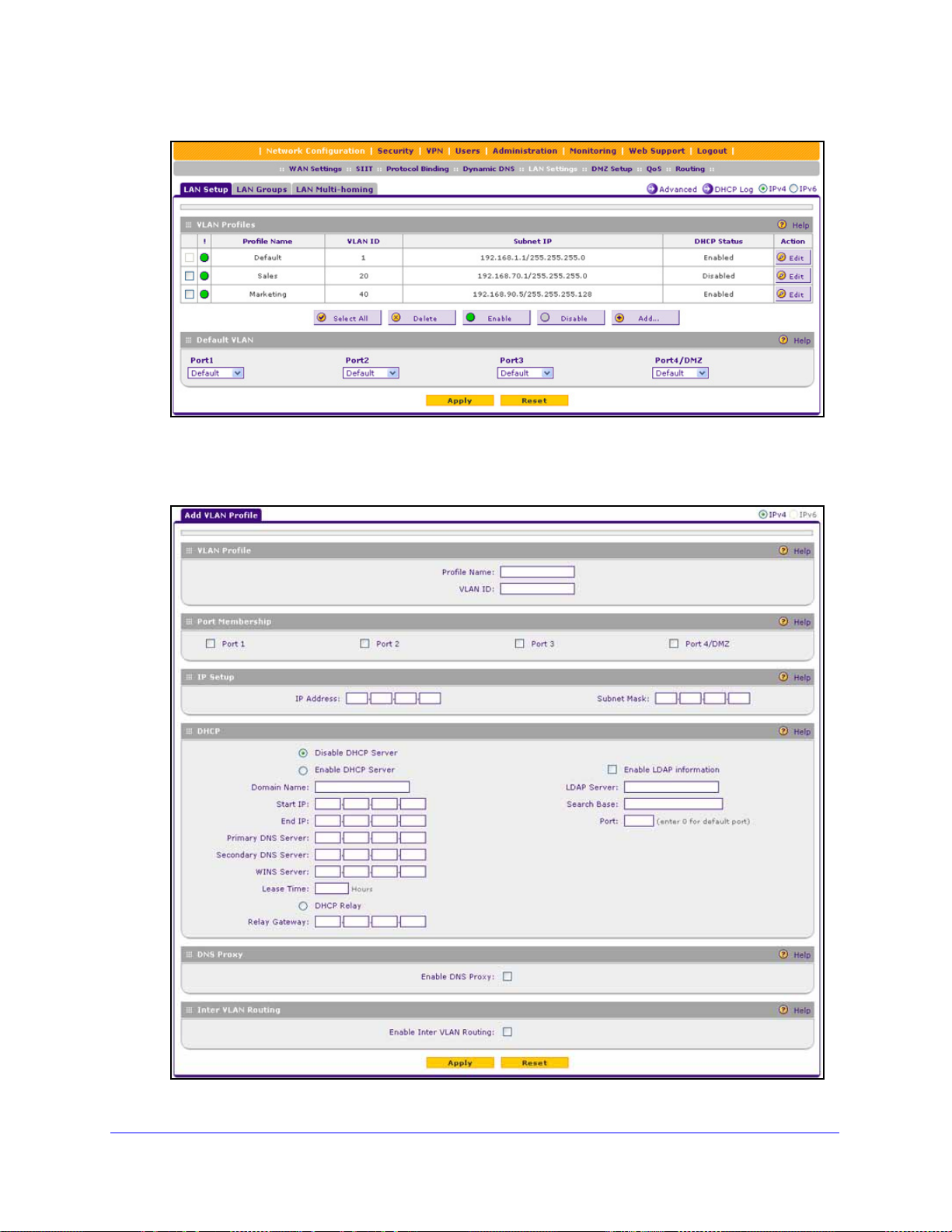
ProSafe Gigabit Quad WAN SSL VPN Firewall SRX5308
Figure 48.
2. Click the Add table button under the VLAN Profiles table. The Add VLAN Profile screen
displays:
Figure 49.
LAN Configuration
84
Page 85

ProSafe Gigabit Quad WAN SSL VPN Firewall SRX5308
3. Enter the settings as explained in the following table:
Table 15. Add VLAN Profile screen settings
Setting Description
VLAN Profile
Profile Name Ente r a unique name for the VLAN profile.
VLAN ID Enter a unique ID number for the VLAN profile. No two VLANs can have the same
VLAN ID number.
Note: You can enter VLAN IDs from 2 to 4089. VLAN ID 1 is reserved for the
default VLAN; VLAN ID 4094 is reserved for the DMZ interface.
Port Membership
ort 1, Port 2, Port 3,
P
Port 4 / DMZ
IP Setup
IP Address
Subnet Mask Enter the IP subnet mask. The subnet mask speci
DHCP
Select one, several, or all port check boxes to make the ports members of this
VLAN.
Note: A port that is defined as a member of a
data frames that are tagged with the VLAN ID.
Enter the IP address of the VPN firewall (the factory default address is
192.168.1.1).
Note: Always make sure that the LAN port IP ad
are in different subnets.
Note: If you change the LAN IP address of
through the browser to the VLAN, you are disconnected. You then need to open
a new connection to the new IP address and log in again. For example, if you
change the default IP address 192.168.1.1 to 10.0.0.1, you now need to ente r
https://10.0.0.1 in your browser to reconnect to the web management interface.
of an IP address. Based on the IP address that you assign, the VPN firewall
automatically calculates the subnet mask. Unless you are implementing
subnetting, use 255.255.255.0 as the subnet mask (computed by the VPN
firewall).
VLAN profile can send and receive
the VLAN while being connected
dress and DMZ port IP address
fies the network number portion
Disable DHCP Server If another device on your network is the DHCP server for the VLAN, or if you will
manually configure the network settings of all of your computers, select the
Disable DHCP Server radio button to disable the DHCP server. Except for the
default VLAN for which the DHCP server is enabled, this is the default setting.
LAN Configuration
85
Page 86

ProSafe Gigabit Quad WAN SSL VPN Firewall SRX5308
Table 15. Add VLAN Profile screen settings (continued)
Setting Description
Enable DHCP Server Select the Enable DHCP Server radio button to enable the VPN firewall to
function as a Dynamic Host Configuration Protocol (DHCP) server, providing
TCP/IP configuration for all computers connected to the VLAN. (For the default
VLAN, the DHCP server is enabled by default.) Enter the following settings:
Domain Name This setting is optional. Enter the domain name of the VPN
firewall.
Start IP Address Enter the start IP address. This address specifies the first of
the contiguous addresses in the IP address pool. Any new
DHCP client joining the LAN is assigned an IP address
between this address and the end IP address. For the default
VLAN, the default start IP address is 192.168.1.100.
End IP Address Enter the end IP address. This address specifies the last of
the contiguous addresses in the IP address pool. Any new
DHCP client joining the LAN is assigned an IP address
between the start IP address and this IP address. For the
default VLAN, the default end IP address is 192.168.1.254.
The start and end DHCP IP addresses should be in the same
network as the LAN IP address of the VPN firewall (that is, the
IP address in the IP Setup section as described earlier in this
table).
Primary DNS
Server
Secondary DNS
Server
WINS Server This setting is optional. Enter a WINS server IP address to
Lease Time Enter a lease time. This specifies the duration for which IP
DHCP Relay To use the VPN firewall as a DHCP relay agent for a DHCP server somewhere
else in your network, select the DHCP Relay radio button. Enter the following
setting:
Relay Gateway The IP address of the DHCP server for which the VPN firewall
This setting is optional. If an IP address is specified, the VPN
firewall provides this address as the primary DNS server IP
address. If no address is specified, the VPN firewall uses the
VLAN IP address as the primary DNS server IP address.
This setting is optional. If an IP address is specified, the VPN
firewall provides this address as the secondary DNS server IP
address.
specify the Windows NetBIOS server, if one is present in your
network.
addresses are leased to clients.
serves as a relay.
LAN Configuration
86
Page 87

ProSafe Gigabit Quad WAN SSL VPN Firewall SRX5308
Table 15. Add VLAN Profile screen settings (continued)
Setting Description
Enable LDAP
information
DNS Proxy
Enable DNS Proxy This setting is optional. To enable the VPN firewall to provide a LAN IP address
To enable the DHCP server to provide Lightw eight Directory Access Protocol
(LDAP) server information, select the Enable LDAP information check box.
Enter the following settings.
LDAP Server The IP address or name of the LDAP server.
Search Base The search objects that specify the location in the directory
tree from which the LDAP search begins. You can specify
multiple search objects, separated by commas. The search
objects include:
• CN (for common name)
• OU (for organizational unit)
• O (for organization)
• C (for country)
• DC (for domain)
For example, to search the Netgea
names of Johnson, you would enter:
cn=Johnson,dc=Netgear,dc=net
Port The port number for the LDAP server. The default setting is 0
(zero).
for DNS address name resolution, select the Enable DNS Proxy check box. This
setting is disabled by default.
r.net domain for all last
Note: When the DNS proxy option is disabled for a VLAN, all DHCP clients
ceive the DNS IP addresses of the ISP but without the DNS proxy IP address.
re
Inter VLAN Routing
Enable Inter VLAN
Routing
This setting is optional. To ensure that traffic is routed only to VLANs for which
inter-VLAN routing is enabled, select the Enable Inter VLAN Routing check box.
This setting is disabled by default. When the Enable Inter VLAN Routing check
box is not selected, traffic from this VLAN is not routed to other VLANs, and traffic
from other VLANs is not routed to this VLAN.
4. Click Apply to save your settings.
Note: Once you have completed the LAN setup, all outbound traffic is
allowed and all inbound traffic is discarded except responses to
requests from the LAN side. For information about how to change
these default traffic rules, see Chapter 4, Firewall Protection.
LAN Configuration
87
Page 88

ProSafe Gigabit Quad WAN SSL VPN Firewall SRX5308
To edit a VLAN profile:
1. On the LAN Setup screen for IPv4 (see Figure 48 on page 84), click the Edit button in
the Action column for the VLAN profile that you want to modify. The Edit VLAN Profile
screen displays. This
screen is identical to the Add VLAN Profile screen (see Figure 49
on page 84).
2. Modif
3. Click Apply to save
To enable, disable, or delete one or more VLAN profiles:
1. On
y the settings as explained in the previous table.
your settings.
the LAN Setup screen for IPv4 (see Figure 48 on page 84), select the check box to
the left of each VLAN profile that you want to enable, disable, or delete, or click the
Select All
2. Click one
• Enable. Ena
table button to select all profiles. (You cannot select the default VLAN profile.)
of the following table buttons:
bles the VLAN or VLANs. The ! status icon changes from a gray circle to
a green circle, indicating that the selected VLAN or VLANs are enabled. (By default,
when a VLAN is added to the table, it is automatically enabled.)
• Disable. Disab
les the VLAN or VLANs. The ! status icon changes from a green circle
to a gray circle, indicating that the selected VLAN or VLANs are disabled.
• Delete. Deletes the VLAN or
VLANs.
Configure VLAN MAC Addresses and LAN Advanced Settings
By default, all configured VLAN profiles share the same single MAC address as the LAN
ports. (All LAN ports share the same MAC address.) However, you can change the VLAN
MAC settings to allow up to 16 VLANs to each be assigned a unique MAC address.
You can also enable or disable the broadcast of Address Resolution Protocol (ARP) packets
for the default VLAN. If the broadcast of ARP packets is enabled, IP addresses can be
mapped to physical addresses (that is, MAC addresses).
To configure a VLAN to have a unique MAC address:
1. Select Netwo
rk Configuration > LAN Settings. In the upper right of the screen, the
IPv4 radio button is selected by default. The LAN submenu tabs display, with the LAN
Setup screen in view, displaying the IPv4 settings (see Figure 48 on p
2. Click the Advan
ced option arrow in the upper middle of the LAN Setup screen. The IPv4
age 84).
LAN Advanced screen displays:
LAN Configuration
88
Page 89

ProSafe Gigabit Quad WAN SSL VPN Firewall SRX5308
Figure 50.
3. From the MAC Address for VLANs drop-down list, select Unique. (The default is Same.)
4. As an option,
clearing the Enable ARP Broadcast check box. (The broadcast of ARP packets is enabled
by default for the default VLAN.)
you can disable the broadcast of ARP packets for the default VLAN by
5. Click App
Note: If you attempt to configure more than 16 VLANs while the MAC
Note: For information about how to configure and enable the LAN traffic
ly to save your settings.
address for VLANs is set to Unique on the IPv4 LAN Advanced
screen, the MAC addresses that are assigned to each VLAN might
no longer be distinct.
meter, see
page 350.
Configure and Enable the LAN Traffic Meter on
Configure IPv4 Multihome LAN IP Addresses on the Default VLAN
If you have computers using different IPv4 networks in the LAN (for example, 17 2.124.10.0 or
192.168.200.0), you can add aliases to the LAN ports and give computers on those networks
access to the Internet, but you can do so only for the default VLAN. The IP address that is
assigned as a secondary IP address needs to be unique and cannot be assigned to a VLAN.
Make sure that any secondary LAN addresses are different from the primary LAN, WAN, and
DMZ IP addresses and subnet addresses that are already configured on the VPN firewall.
LAN Configuration
89
Page 90

ProSafe Gigabit Quad WAN SSL VPN Firewall SRX5308
The following is an example of correctly configured IPv4 addresses:
• WAN IP address. 10.0.0.1 with subnet 255.0.0.0
• DMZ IP a
• Primary LAN IP ad
• Seco
To add a secondary LAN IPv4 address:
1. Select Network Configuratio
ddress. 176.16.2.1 with subnet 255.255.255.0
dress. 192.168.1.1 with subnet 255.255.255.0
ndary LAN IP address. 192.168.20.1 with subnet 255.255.255.0
n > LAN Settings > LAN Multi-homing. In the upper right
of the screen, the IPv4 radio button is selected by default. The LAN Multi-homing screen
displays the IPv4 settings. (The following figure contains one example.)
Figure 51.
The Available Secondary LAN IPs table displays the secondary LAN IP addre sses added
to the VPN firewall.
the Add Secondary LAN IP Address section of the screen, enter the following settings:
2. In
• IP Address. Ent
• Subnet Mask.
3. Click the Add t
er the secondary address that you want to assign to the LAN ports.
Enter the subnet mask for the secondary IP address.
able button in the rightmost column to add the secondary IP address to the
Available Secondary LAN IPs table.
Repeat Step 2 and Step 3 for each secondary IP address that you want to add to the
Available Secondary LAN IPs table.
Note: Secondary IP addresses cannot be configured in the DHCP server.
The hosts on the secondary subnets need to be manua lly configured
with the IP addresses, gateway IP address, and DNS server IP
addresses.
LAN Configuration
90
Page 91

ProSafe Gigabit Quad WAN SSL VPN Firewall SRX5308
To edit a secondary LAN IP address:
1. On the LAN Multi-homing screen for IPv4 (see the previous figure), click the Edit button
in the Action column for the secondary IP address that you want to modify. The Edit
LAN Multi-homing screen displays.
2. Mo
3. Click App
To delete one or more secondary LAN IP addresses:
dify the IP address or subnet mask, or both.
ly to save your settings.
1. On th
2. Click the Del
e LAN Multi-homing screen for IPv4 (see the previous figure), select the check box
to the left of each secondary IP address that you want to delete, or click the Select All
table button to select secondary IP addresses.
ete table button.
Manage IPv4 Groups and Hosts (IPv4 LAN Groups)
• Manage the Network Database
• Change Group Names in the Network Database
• Set Up DHCP Address Reservation
The Known PCs and Devices table on the LAN Groups (IPv4) screen (see Figure 5
page 93) contains a list of all known computers and network devices that are assigned
dynamic IP addresses by the VPN firewall, have been discovered by other means, or were
entered manually. Collectively, these entries make up the network database.
The network database is updated by these methods:
• DHCP client
DHCP client requests from computers and other network devices. These requests also
generate an entry in the network database. This is an advantage of enabling the DHCP
server feature.
• Sca
nning the network. The local network is scanned using Address Resolution Protocol
(ARP) requests. The ARP scan detects active devices that are not DHCP clients.
requests. When the DHCP server is enabled, it accepts and responds to
2 on
Note: In large networks, scanning the network might generate unwanted
traffic.
Note: When the VPN firewall receives a reply to an ARP request, it might
not be able to determine the device name if the software firewall of
the device blocks the name.
• Manual entry. You can manually enter information about a network device.
LAN Configuration
91
Page 92

ProSafe Gigabit Quad WAN SSL VPN Firewall SRX5308
These are some advantages of the network database:
• Generally, you do not need to enter an IP address or a MAC address. Instead, you can
select the name of the desired computer or device.
• There
is no need to reserve an IP address for a computer in the DHCP server. All IP
address assignments made by the DHCP server are maintained until the computer or
device is removed from the network database, either by expiration (inactive for a long
time) or by you.
• There
• A compute
• Control ove
is no need to use a fixed IP address on a computer. Because the IP address
allocated by the DHCP server never changes, you do not need to assign a fixed IP
address to a computer to ensure that it always has the same IP address.
r is identified by its MAC address—not its IP address. The network database
uses the MAC address to identify each computer or device. Therefore, changing a
computer’s IP address does not affect any restrictions applied to that computer.
r computers can be assigned to groups and individuals:
- Y
ou can assign computers to groups (see Manage the Network Database on this
page) and apply restrictions (outbound rules and inbound rules) to each group (see
Overview of Rules to Block or Allow Specific Kind
- Y
ou can select groups that are allowed access to URLs that you have blocked for
other groups, or the other way around, block access to URLs that you have allowed
access to for groups (see Configure Content Filtering on p
- If necessary
Enable Source MAC Filtering on p
identify each computer, users cannot avoid the
address.
, you can also create firewall rules to apply to a single computer (see
age 186). Because the MAC address is used to
s of Traffic on page 131).
age 181).
se restrictions by changing their IP
Manage the Network Database
You can view the network database, manually add or remove database entries, and edit
database entries.
To view the network database, select Network Configuration > LAN Settings > LAN
Groups. The LAN Groups screen displays. (The following figure shows some manually
added devices in the Known PCs and Devices table as an example.)
LAN Configuration
92
Page 93

ProSafe Gigabit Quad WAN SSL VPN Firewall SRX5308
Figure 52.
The Known PCs and Devices table lists the entries in the network database. For each
computer or device, the following fields display:
• Check box. Allows you to select the computer or device in the table.
• Name. The
name of the computer or device. For computers that do not support the
NetBIOS protocol, the name is displayed as Unknown (you can edit the entry manually to
add a meaningful name). If the computer or device was assigned an IP address by the
DHCP server, then the name is appended by an asterisk.
• IP
Address. The current IP address of the computer or device. For DHCP clients of the
VPN firewall, this IP address does not change. If a computer or device is assigned a
static IP address, you need to update this entry manually after the IP address on the
computer or device has changed.
• M
AC Address. The MAC address of the computer or device’s network interface.
• Group. Each compu
ter or device can be assigned to a single LAN group. By default, a
computer or device is assigned to Group 1. You can select a different LAN group from the
Group drop-down list in the Add Known PCs and Devices section or on the Edit Groups
and Hosts screen.
• Profile
Name. Each computer or device can be assigned to a single VLAN. By default, a
computer or device is assigned to the default VLAN (VLAN 1). You can select a different
VLAN profile name from the Profile Name drop-down list in the Add Known PCs and
Devices section or on the Edit Groups and Hosts screen.
• Action. The
Edit table button, which provides access to the Edit Groups and Hosts
screen.
LAN Configuration
93
Page 94

ProSafe Gigabit Quad WAN SSL VPN Firewall SRX5308
Add Computers or Devices to the Network Database
To add computers or devices manually to the network database:
1. In t
he Add Known PCs and Devices section of the LAN Groups screen (see the previous
figure), enter the settings as explained in the following table:
Table 16. Add Known PCs and Devices section settings
Setting Description
Name Enter the name of the computer or device.
IP Address Type From the drop-down list, select how the computer or device receives its IP address:
• Fixed (set on PC). The IP address is statically assigned on the computer or
device.
eserved (DHCP Client). The DHCP server of the VPN firewall always assigns
• R
the specified IP address to this client during th e DHCP negotiation (see also Set
Up DHCP Address Reservation on
Note: For both types of IP addresses, the VPN firewall reserves the IP address for
e associated MAC address.
th
IP Address Enter the IP address that this computer or device is assigned to:
• If the IP address type is Fixed (set on PC), the IP address needs to be outside of
e address range that is allocated to the DHCP server poo l to prevent the IP
th
address from also being allocated by th e DHCP server.
• If the IP address type is Reserved (DHCP Clie
outside the address range that is allocated to the D HCP server pool.
Note: Make sure that the IP address is in the IP
you select from the Profile Name drop-down list.
page 96).
nt), the IP address can be inside or
subnet for the VLAN profile that
MAC Address Enter the MAC address of th
address format is six colon-separated pairs of hexadecimal characters (0–9 and
a–f), such as 01:23:d2:6f:89:ab.
Group From the drop-down list, select the group to which the computer or device is
assigned. (Group 1 is the default group.)
Profile Name From the drop-down list, select the name of the VLAN profile to which the computer
or device is assigned.
2. Click the Add t
able button to add the computer or device to the Known PCs and Devices
e computer’s or device’s network interface. The MAC
table.
3. As
an optional step: To save the binding between the IP address and MAC address for the
entry that you just added to the Known PCs and Devices table, select the check box for the
table entry, and click the Save Binding button.
Note: The saved binding is also displayed on the IP/MAC Binding screen
(see Figure 112 on page 188).
LAN Configuration
94
Page 95

ProSafe Gigabit Quad WAN SSL VPN Firewall SRX5308
Edit Computers or Devices in the Network Database
To edit computers or devices manually in the network database:
1. I
n the Known PCs and Devices table of the LAN Groups screen (see Figure 52 on
page 93), click the Ed
displays (see the following figure, which contains an example).
it table button of a table entry. The Edit LAN Groups screen
Figure 53.
2. Modify the settings as explained in Table 16 on page 94.
3. Click App
ly to save your settings in the Known PCs and Devices table.
Deleting Computers or Devices from the Network Database
To delete one or more computers or devices from the network database:
1. On the
of each computer or device that you want
to select all computers and devices.
2. Click the Del
LAN Groups screen (see Figure 52 on page 93), select the check box to the left
to delete, or click the Select All table button
ete table button.
Note: If you delete a saved binding between an IP and MAC address on
the LAN Groups screen, make sure that you also delete the binding
on the IP/MAC Binding screen (see Figure 112 on page 188).
Change Group Names in the Network Database
By default, the groups are named Group1 through Group8. You can change these group
names to be more descriptive, such as GlobalMarketing and GlobalSales.
LAN Configuration
95
Page 96

ProSafe Gigabit Quad WAN SSL VPN Firewall SRX5308
To edit the name of one of the eight available groups:
1. Select Network Configuration > LAN Settings > LAN Groups. The LAN Groups
screen displays (see Figure 52 on
page 93, which shows some examples in the Known
PCs and Devices table).
2. Click the Edit Group
Names option arrow to the right of the LAN submenu tabs. The
Network Database Group Names screen displays. (The following figure shows some
examples.)
Figure 54.
3. Select the radi o button next to the group name that you want to change.
4. T
ype a new name in the field. The maximum number of characters is 15. Do not use a
double quote (''), single quote('), or space in the name.
5. Click Apply to save
your settings.
Note: You can change only one group name at a time.
Set Up DHCP Address Reservation
When you specify a reserved IP address for a computer or device on the LAN (based on the
MAC address of the device), that computer or device always receives the same IP address
each time it accesses the VPN firewall’s DHCP server. Reserved IP addresses should be
assigned to servers or access points that require permanent IP address settings. The
reserved IP address that you select needs to be outside of the DHCP server pool.
To reserve and bind an IP address to a MAC address, select Reserved (DHCP Client) from
the IP Address Type drop-down list on the LAN Groups screen and save the binding by
clicking the Save Binding button on the same screen. For det ailed steps, see Add Computers
or Devices to the Network Database on page 94.
LAN Configuration
96
Page 97

ProSafe Gigabit Quad WAN SSL VPN Firewall SRX5308
Note: The reserved address is not assigned until the next time the
computer or device contacts the VPN firewall’s DHCP server.
Reboot the computer or device, or access its IP configuration and
force a DHCP release and renew.
Note: The saved binding is also displayed on the IP/MAC Binding screen
(see Figure 112 on page 188).
Manage the IPv6 LAN
• DHCPv6 Server Options
• Configure the IPv6 LAN
• Configure the IPv6 Router Advertisement Daemon and Advertisement Prefixes for the
LAN
An IPv6 LAN typically functions with site-local and link-local unicast addresses. Each
physical interface requires an IPv6 link-local address that is automatically derived from the
MAC addresses of the IPv4 interface and that is used for address configuration and neighbor
discovery. (Normally, you would not manually configure a link-local address.)
Traffic wit h site-local or link-local addresses is never forwarded by the VPN firewall (or by any
other router), that is, the traffic remains in the LAN subnet and is processed over the default
VLAN only. A site-local address always starts with fec0 (hexadecimal); a link-local unicast
address always starts with FE80 (hexadecimal). To forward traffic from sources with a site
local or link-local unicast address in the LAN, a DHCP server is required. For more
information about link-local unicast addresses, see Configure ISATAP Automatic Tunneling
on page 64.
Because each interface is automatically assigned a link-local IP address, it is not useful to
assign another link-local IP address as the default IPv6 LAN address. The default IPv6 LAN
address is a site-local address. You can change this address to any other IPv6 address for
LAN use.
Note: Site-local addresses, that is, addresses that start with fec0, have
been depreciated. However, NETGEAR has implemented a
site-local address as a temporary default IPv6 LAN address that you
can replace with another LAN address. The firewall restricts external
communication of this default site-local address.
LAN Configuration
97
Page 98

ProSafe Gigabit Quad WAN SSL VPN Firewall SRX5308
DHCPv6 Server Options
The IPv6 clients in the LAN can autoconfigure their own IPv6 address or obtain an IPv6
address through a DHCPv6 server. For the LAN, there are three DHCPv6 options:
Stateless DHCPv6 Server
The IPv6 clients in the LAN generate their own IP address by using a combination of locally
available information and router advertisements, but receive DNS server information from the
DHCPv6 server. For stateless DHCPv6, you need to configure the RADVD and
advertisement prefixes (see Configure the IPv6 Router Advertisement Daemon and
Advertisement Prefixes for the LAN on page 104).
Stateless DHCPv6 Server With Prefix Delegation
As an option for a stateless DHCPv6 server, you can enable prefix delegation. The ISP’s
stateful DHCPv6 server assigns a prefix that is used by the VPN firewall’ s stateless DHCPv6
server to assign to its IPv6 LAN clients.
Prefix delegation functions in the following way:
1. The VPN firewall’
You need to select the Prefix Delegation check box on the
(see Use a DHCPv6 Server to Configure an IPv6 Internet Connection on
e ISP allocates a prefix to the VPN f ir e wa ll .
2. Th
This prefix is automatically added to the List of Prefixes to Advertise table on the LAN
RA
DVD screen for IPv6 (see Configure the IPv6 Router Advertisement Daemon and
Advertisement Prefixes for the LAN on
3. Th
e stateless DHCPv6 server allocates the prefix to the IPv6 LAN clients through the
RADVD. When prefix delegation is enabled, the RADVD advertises the following prefixes:
• The p
• Prefixes that
You need to perform the following tasks:
• Select the
• Config
• Op
refix that was added through prefix delegation.
RADVD screen.
Configure the IPv6 LAN on
ure the RADVD (see Configure the IPv6 Router Advertisement Daemon and
Advertisement Prefixes for the LAN on
tionally, manually add prefixes to the List of Prefixes for Prefix Delegation table on
the LAN Setup screen for IPv6 (see IPv6 LAN Prefixes for Prefix Delegation on
page 103).
s DHCPv6 client requests prefix delegation from the ISP.
ISP IPv6 WAN Settings screen
page 54).
page 104).
you manually added to the List of Prefixes to Advertise table on the
Prefix Delegation check box on the LAN Setup screen for IPv6 (see
page 99).
page 104).
• Op
tionally, manually add prefixes to List of Prefixes to Advertise table on the RADVD
screen (see Advertisement Prefixes for the LAN on p
LAN Configuration
98
age 106).
Page 99

ProSafe Gigabit Quad WAN SSL VPN Firewall SRX5308
Stateful DHCPv6 Server
The IPv6 clients in the LAN obtain an interface IP address, configuration information such as
DNS server information, and other parameters from the DHCPv6 server . The IP address is a
dynamic address. For stateful DHCPv6, you need to configure IPv6 address pools (see IPv6
LAN Address Pools on page 101).
Configure the IPv6 LAN
To configure the IPv6 LAN settings:
1. Select Network Configuratio
2. In the uppe
the IPv6 settings. (The following figure contains some examples.)
r right of the screen, select the IPv6 radio button. The LAN Setup screen displays
n > LAN Settings.
Figure 55.
LAN Configuration
99
Page 100

ProSafe Gigabit Quad WAN SSL VPN Firewall SRX5308
3. Enter the settings as explained in the following table. The IPv6 address pools and prefixes
for prefix delegation are explained in the sections following the table.
Table 17. LAN Setup screen settings for IPv6
Setting Description
IPv6 LAN Setup
IPv6 Address Enter the LAN IPv6 address. The default address is fec0::1.(For more information, see
the introduction to this section, Manage the IPv6 LAN.)
IPv6 Prefix Length Enter the IPv6 prefix length, for example, 10 or 64. The default prefix length is 64.
DHCPv6
DHCP Status Specify the status of the DHCPv6 server:
• Disable DHCPv6 Server. This is the default setting, and the DHCPv6 fiel ds are
masked out.
able the DHCPv6 Server. If you enable the server, you need to complete the
• En
DHCPv6 fields.
DHCP Mode Select one of the DHCPv6
tateless. The IPv6 clients generate their own IP address by
• S
using a combination of locally available information and router
advertisements, but receive DNS server information from the
DHCPv6 server. For stateless DHCPv6, you need to configure
the RADVD and advertisement prefixes (see Configure the
IPv6 Router Advertisement Daemon and Advertisement
Prefixes for the LAN on p
enable prefix delegation (see the explan ation further down in
this table).
ateful. The IPv6 clients obtain an interface IP address,
• St
configuration information such as DNS server information, and
other parameters from the DHCPv6 server. The IP address is a
dynamic address. You need to add IPv6 address pools to the
List of IPv6 Address Pools table on the LAN Setup screen (see
IPv6 LAN Address Pools o
Prefix Delegation If you have selected the st
the Prefix Delegation check box:
fix delegation check box is selected. The stateless
• Pre
DHCPv6 server assigns prefixes to its IPv6 LAN clients. Make
sure that the Prefix Delegation check box on the WAN IPv6
ISP Settings screen is also selected (see Use a DHCPv6
Server to Configure an IPv6 Internet Connection on p
to enable the VPN firewall to acquire a prefix from the ISP
ugh prefix delegation. In this configuration, a prefix is
thro
automatically added to the List of Prefixes to Advertise table on
the LAN RADVD screen for IPv6 (see Configure the IPv6
Router Advertisement Daemon and
the LAN on p
• Prefix delegation check b ox is cleared. Prefix delegation is
disabled in the LAN. This is the default setting.
age 104).
modes from the drop-down list:
age 104). As an option, you can
n page 101).
ateless DHCPv6 mode, you can select
age 54)
Advertisement Prefixes for
Domain Name Enter the domain name of the DHCP server.
LAN Configuration
100
 Loading...