

Netgear S3300-52X GS752TX, S3300-28X GS728TX, S3300-28X-PoE+ GS728TXP, S3300-52X-PoE+ GS752TXP User manual
Page 1

ProSAFE S3300 Smart Switch
Hardware Installation Guide
August 2014
202-11445-01
350 East Plumeria Drive
San Jose, CA 95134
USA
Page 2

S3300 Smart Switch
Support
Thank you for selecting NETGEAR products.
After installing your device, locate the serial number on the label of your product and use it to register your product at
https://my.netgear.com. You must register your product before you can use NETGEAR telephone support. NETGEAR
recommends registering your product through the NETGEAR website. For product updates and web support, visit
http://support.netgear.com.
Phone (US & Canada only): 1-888-NETGEAR.
Phone (Other Countries): Check the list of phone numbers at http://support.netgear.com/general/contact/default.aspx.
Compliance
For regulatory compliance information, visit http://www.netgear.com/about/regulatory.
See the regulatory compliance document before connecting the power supply.
Trademarks
NETGEAR, the NETGEAR logo, and Connect with Innovation are trademarks and/or registered trademarks of NETGEAR, Inc.
and/or its subsidiaries in the United States and/or other countries. Information is subject to change without notice.
© NETGEAR, Inc. All rights reserved.
Revision History
Publication Part Number Publish Date Comments
202-11445-01 August 2014 First publication
2
Page 3

Contents
Chapter 1 Introduction
Chapter 2 Physical Description
Hardware Overview . . . . . . . . . . . . . . . . . . . . . . . . . . . . . . . . . . . . . . . . . . . . . . . . . . . 6
Hardware Features . . . . . . . . . . . . . . . . . . . . . . . . . . . . . . . . . . . . . . . . . . . . . . . . . . . . 6
Stacking . . . . . . . . . . . . . . . . . . . . . . . . . . . . . . . . . . . . . . . . . . . . . . . . . . . . . . . . . . . . .8
Package Contents. . . . . . . . . . . . . . . . . . . . . . . . . . . . . . . . . . . . . . . . . . . . . . . . . . . . . 9
S3300-52X and S3300-52X-PoE+ Description . . . . . . . . . . . . . . . . . . . . . . . . .11
S3300-52X Front Panel and Back Panel Configuration . . . . . . . . . . . . . . . . .11
LED Designations . . . . . . . . . . . . . . . . . . . . . . . . . . . . . . . . . . . . . . . . . . . . . . . . . .13
S3300-28X and S3300-28X-PoE+ Description . . . . . . . . . . . . . . . . . . . . . . . . .14
S3300-28X Front Panel and Back Panel Configuration . . . . . . . . . . . . . . . . .14
LED Designations . . . . . . . . . . . . . . . . . . . . . . . . . . . . . . . . . . . . . . . . . . . . . . . . . .17
Device Hardware Interfaces . . . . . . . . . . . . . . . . . . . . . . . . . . . . . . . . . . . . . . . . . . .18
RJ-45 Ports . . . . . . . . . . . . . . . . . . . . . . . . . . . . . . . . . . . . . . . . . . . . . . . . . . . . . .18
10GBASE-T Ports . . . . . . . . . . . . . . . . . . . . . . . . . . . . . . . . . . . . . . . . . . . . . . . . .19
SFP+ Ports . . . . . . . . . . . . . . . . . . . . . . . . . . . . . . . . . . . . . . . . . . . . . . . . . . . . . . .19
Reset Button. . . . . . . . . . . . . . . . . . . . . . . . . . . . . . . . . . . . . . . . . . . . . . . . . . . . . .19
Factory Defaults Button . . . . . . . . . . . . . . . . . . . . . . . . . . . . . . . . . . . . . . . . . . . .19
USB Port . . . . . . . . . . . . . . . . . . . . . . . . . . . . . . . . . . . . . . . . . . . . . . . . . . . . . . . . .20
PoE Ports . . . . . . . . . . . . . . . . . . . . . . . . . . . . . . . . . . . . . . . . . . . . . . . . . . . . . . . . .20
Chapter 3 Desktop and Backbone Switching
Desktop Switching . . . . . . . . . . . . . . . . . . . . . . . . . . . . . . . . . . . . . . . . . . . . . . . . . . .22
Backbone Switching. . . . . . . . . . . . . . . . . . . . . . . . . . . . . . . . . . . . . . . . . . . . . . . . . .23
Chapter 4 Installation
Step 1: Prepare the Site. . . . . . . . . . . . . . . . . . . . . . . . . . . . . . . . . . . . . . . . . . . . . . .25
Step 2: Install the Switch. . . . . . . . . . . . . . . . . . . . . . . . . . . . . . . . . . . . . . . . . . . . . . 25
Install the Switch on a Flat Surface . . . . . . . . . . . . . . . . . . . . . . . . . . . . . . . . . . .25
Install the Switch in a Rack . . . . . . . . . . . . . . . . . . . . . . . . . . . . . . . . . . . . . . . . . .26
Step 3: Check the Installation. . . . . . . . . . . . . . . . . . . . . . . . . . . . . . . . . . . . . . . . . .27
Step 4: Connect Devices to the Switch. . . . . . . . . . . . . . . . . . . . . . . . . . . . . . . . . . 27
Step 5: Install an SFP Transceiver Module . . . . . . . . . . . . . . . . . . . . . . . . . . . . . . .28
Step 6: Install the Smart Switch as a Stack Master or Stack Slave . . . . . . . . . . .29
Step 7: Apply AC Power . . . . . . . . . . . . . . . . . . . . . . . . . . . . . . . . . . . . . . . . . . . . . .29
Step 8: Install the RPS and Apply RPS DC Power. . . . . . . . . . . . . . . . . . . . . . . . . . 30
Contents | 3
Page 4

S3300 Smart Switch
Step 9: Manage the Switch Through a Web Browser or
the Smart Control Center Utility. . . . . . . . . . . . . . . . . . . . . . . . . . . . . . . . . . . . . . . 30
Appendix A Troubleshooting
Troubleshooting Chart . . . . . . . . . . . . . . . . . . . . . . . . . . . . . . . . . . . . . . . . . . . . . . . 32
Additional Troubleshooting Suggestions . . . . . . . . . . . . . . . . . . . . . . . . . . . . . . . . 33
Appendix B Physical and Technical Specifications
4
Page 5

1. Introduction
1
The NETGEAR® ProSAFE® S3300 Smart Switch is a high-performance, IEEE-compliant,
stackable switch with either 48 (models S3300-52X and S3300-52X-PoE+) or 24 (models
S3300-28X and S3300-28X-PoE+) twisted-pair ports on the front panel to support
10/100/1000 Mbps networks. In addition, the front panel provides two dedicated 10GBASE-T
ports and two dedicated SFP+ ports for connections to a server or network backbone.
configure the dedicated 10GBASE-T and SFP+ ports as stacking links to build a stack system
with other S3300 switches. To simplify installation, the smart switch is shipped ready for use out
of the box.
This hardware installation guide complements the installation guide that came with your smart
switch.
This chapter serves as an introduction to the smart switch and includes the following sections:
• Hardware Overview
• Hardware Features
• Stacking
• Package Contents
Y
ou can
Note: For more information about the topics that are covered in this manual,
visit the support website at support.netgear.com.
Note: In this manual, the S3300 Smart Switch is referred to as the smart switch.
5
Page 6

S3300 Smart Switch
Hardware Overview
This installation guide is for the following S3300 Smart Switch models:
• S3300-52X. Supports forty eight 10/100/1000 Mbps ports, two dedicated
100M/1G/10GBASE-T ports, and two dedicated 10G/1G SFP+ ports.
• S3300-52X-PoE+. Supports forty eight 10/100/1000 Mbps PoE+ capable ports
(IEEE 802.1at), two dedicated 100M/1G/10GBASE-T ports, and two dedicated 10G/1G
SFP+ ports.
• S3300-28X. Supports twenty four 10/100/1000 Mbps ports, two dedicated
100M/1G/10GBASE-T ports, and two dedicated 10G/1G SFP+ ports.
• S3300-28X-PoE+. Supports twenty four 10/100/1000 Mbps PoE+ capable ports
(IEEE 802.1at), two dedicated 100M/1G/10GBASE-T ports, and two dedicated 10G/1G
SFP+ ports.
You can configure the dedicated 10GBASE-T and SFP+ ports on the smart switch either as
Ethernet ports or as stacking links.
Using these 10G copper and fiber ports, you can also create high-speed connections to a
server or network backbone. For example, you can do the following:
• Connect switches to each other with high-speed links
• Link to high-speed servers
• Provide 10G/1G/100M copper and 10G/1G fiber connectivity
• Connect up to six switches in a stack to create a high-port-capacity solution with a single
point of administration
The smart switch can be freestanding, stacked with other switches, or rack-mounted in a
wiring closet or equipment room. It is IEEE compliant and of
networking.
All ports can automatically negotiate to the highest speed, which makes the smart switch very
suitable for environments with a mix of Ethernet, Fast Ethernet, Gigabit Ethernet, or
10-Gigabit Ethernet devices. The 10/100 Mbps ports can operate in half-duplex or full-duplex
mode.
The maximum segment length is 328 feet (100 meters) over Category 5 unshielded
twisted-pair (UTP) cable. For 10GBASE-T connections, NETGEAR recommends that you
use a Category 6a cable or a cable that is even higher rated.
The 10G/1G ports always operate in full-duplex mode.
fers low latency for high-speed
Hardware Features
The S3300 Smart Switch includes the following key hardware features:
• Forty eight (S3300-52X and S3300-52X-PoE+) or twenty four (S3300-28X and
S3300-28X-PoE+) 10/100/1000 Mbps autosensing Gigabit Ethernet switching ports.
• Two dedicated 100M/1G/10GBASE-T ports.
Introduction
6
Page 7

S3300 Smart Switch
• Two dedicated 10G/1G SFP+ ports.
• One USB port to support firmware upgrades from a disk and backups to a storage device.
• Full NETGEAR Smart Switch functionality
.
• Full compatibility with IEEE standards:
- IEEE 802.3i (10BASE-T)
- IEEE 802.3u (100BASE-TX)
- IEEE 802.3ab (1000BASE-T)
- IEEE 802.3an (10GBASE-T)
- IEEE 802.3z (1000BASE-X)
- IEEE 802.3 Clause 49 (10GBASE-LR and 10GBASE-SR)
- IEEE802.aq (10GBASE-LRM)
- IEEE802.3ae (10GBASE Ethernet)
- IEEE802.3az (Energy Ef
ficient Ethernet)
- IEEE 802.3x (Full-duplex flow control)
- IEEE 802.1at (PoE+)
• AutoSensing and autonegotiating capabilities for all ports.
• Auto Uplink technology is supported on all ports.
• Automatic address learning function to build the packet-forwarding information table.
table contains up to 16K Media
Access Control (MAC) addresses.
The
• Store-and-forward transmission to remove bad packets from the network.
• Full-duplex IEEE 802.3x pause frame flow control.
• Active flow control to minimize packet loss and frame drops.
• Half-duplex backpressure control.
• Per-port status LEDs and system status LEDs.
• Internal open frame power supply
.
• Standard NETGEAR chassis (1U high).
• NETGEAR green power-saving features:
- Energy ef
ficiency mode that fully conforms to the IEEE802.3az standard
- Per-port automatic change to a lower power mode when the port link is down
• Support for Power over Ethernet (PoE+) on models S3300-52X-PoE+ and
S3300-28X-PoE+.
• Support for an RPS4000 external power supply to provide a larger power budget for
model S3300-52X-PoE+ or model S3300-28X-PoE+.
Introduction
7
Page 8

S3300 Smart Switch
Stacking
A single switch can control and manage a stack. This switch is referred to as the stack
master, or simply, the master. Any other members in the stack are referred to as slaves. All
switches in a stack are stack members.
Slaves can download firmware from the master and the master can push firmware to the
slaves.
The master runs the fully operational software of a switch. In addition, the master runs the
master software of the distributed switching application that configures and manages all
slaves. Generally, the master operates the remote slave’
distributed switching application part that is running in the context of the slave.
During stacking setup, the switches autoselect one switch as the master. All other switches
become slaves and are assigned unique stack IDs. One of the slaves is designated as the
backup master.
original master fails. In the default configuration, the master and backup master are assigned
unit IDs of 1 and 2, respectively. You can use the web management interface to configure
different ID assignments. The master provides a single point of control and management as
well as a single interface through which to control and manage the stack.
The backup master functions as a slave but can become the master if the
s low-level drivers through the
Switch software is downloaded separately for each stack member. However, all stack
members must be running the same software version.
A stack unit can operate in one of the following modes:
• A standalone switch runs as a general switch.
stacking application until it is connected to a stack.
• A master manages the entire stack and is responsible for the entire stack configuration.
All protocols run in the context of the master, which updates and synchronizes the backup
master
• A backup master runs as a slave until it must take over from the master. In addition, the
backup master continuously monitors the existence and operation of the master
master fails, the backup master assumes the role of master through a switchover.
• A slave runs only a slave version of the distributed switching software, which allows the
applications running on the master to control and manage the resources of the slave.
A stack can contain a mix of up to six S3300 switches. All S3300 models support stacking.
.
The standalone unit does not run the
. If the
Introduction
8
Page 9
S3300 Smart Switch
Package Contents
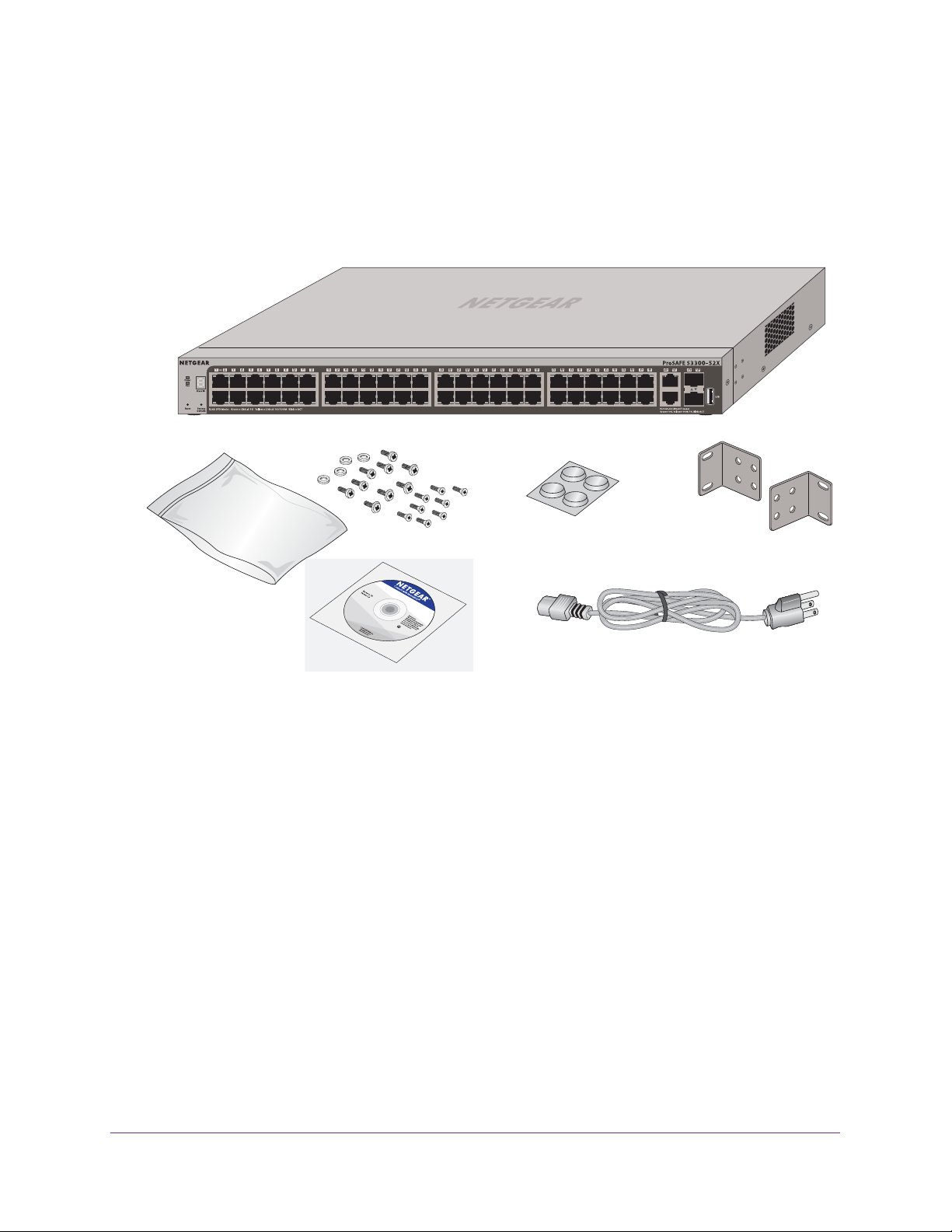
The following figure shows the package contents of the S3300 Smart Switch. The figure
shows model S3300-52X. However, the package contents for the other models are the same.
Figure 1. Package contents
Verify that the package contains the following:
• S3300 Smart Switch
• Rubber footpads for tabletop installation
• Rack-mounting kit
• Power cord
• Quick installation guide
• Smart switch resource CD with NETGEAR Smart Control Center and a link to the S3300
Smart Switch Software
If any item is missing or damaged, contact the vendor immediately
Administration Manual.
.
Introduction
9
Page 10

2. Physical Description
This chapter describes the S3300 Smart Switch hardware features.
The chapter includes the following sections:
• S3300-52X and S3300-52X-PoE+ Description
• S3300-28X and S3300-28X-PoE+ Description
• Device Hardware Interfaces
2
10
Page 11
S3300 Smart Switch
S3300-52X and S3300-52X-PoE+ Description
This section describes the smart switch hardware features for models S3300-52X and
S3300-52X-PoE+.
S3300-52X Front Panel and Back Panel Configuration
The S3300-52X and S3300-52X-PoE+ models provide forty eight 10/100/1000 Mbps ports,
two dedicated 100M/1G/10GBASE-T ports, and two dedicated 10G/1G Gbps SFP+ ports.
Each port can sense the line speed and negotiate the duplex mode with the link partner
automatically. Model S3300-52X-PoE+ supports PoE+ on ports 1 through 48.
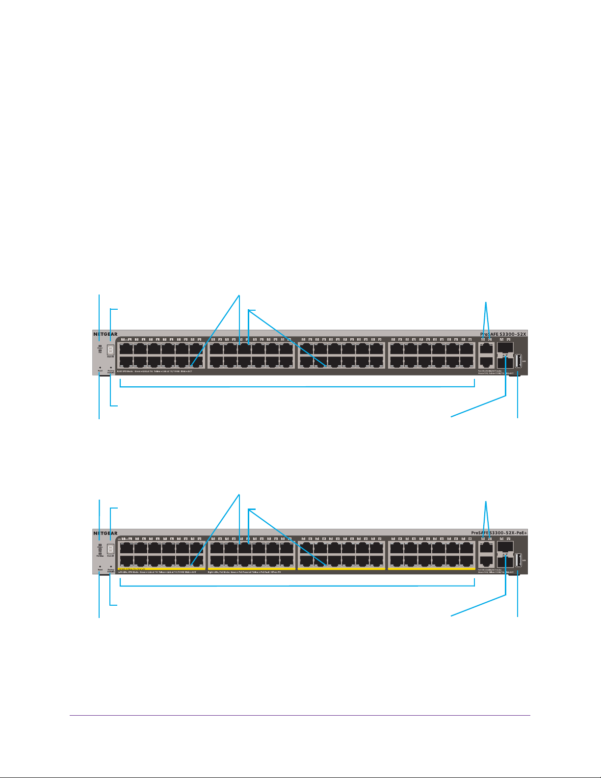
The following figures illustrate the front panel of models S3300-52X and S3300-52X-PoE+.
Power and Fan LEDs
Stack ID LED
Factory Defaults button
Reset button
Figure 2. Front panel model S3300-52X
Power, Fan, and
PoE MAX LEDs
Stack ID LED
Left LEDs: RJ45 SPD Mode LED
10/100/1000 Mbps ports
Left LEDs: RJ45 SPD Mode LED
Right LEDs: nonfunctioning
Right LEDs: PoE Mode LED
SFP+ ports
Link/ACT LEDs
10G ports
Link/ACT LEDs
USB port
10G ports
Link/ACT LEDs
10/100/1000 Mbps PoE ports
Factory Defaults button
Reset button
Figure 3. Front panel model S3300-52X-PoE+
Physical Description
11
SFP+ ports
Link/ACT LEDs
USB port
Page 12
S3300 Smart Switch
The front panel provides the following components:
• Forty eight RJ-45 connectors for 10/100/1000 Mbps autosensing Gigabit Ethernet
switching ports
• Two 100M/1G/10GBASE-T copper ports (49–50) that you can also use for stacking
• Two 10G/1G SFP+ fiber ports (51–52) that you can also use for stacking
• One USB 2.0 port that supports FA
T32 and VF
AT file systems
• Reset button to restart the device
• Recessed Factory Defaults button to restore the device back to the factory defaults
• Link, Speed, and
Activity LEDs for each port and for the PoE model, PoE LEDs for
ports 1–48
• Power, Fan, and Stack ID LEDs; for model S3300-52X-PoE+ only, PoE Max LED
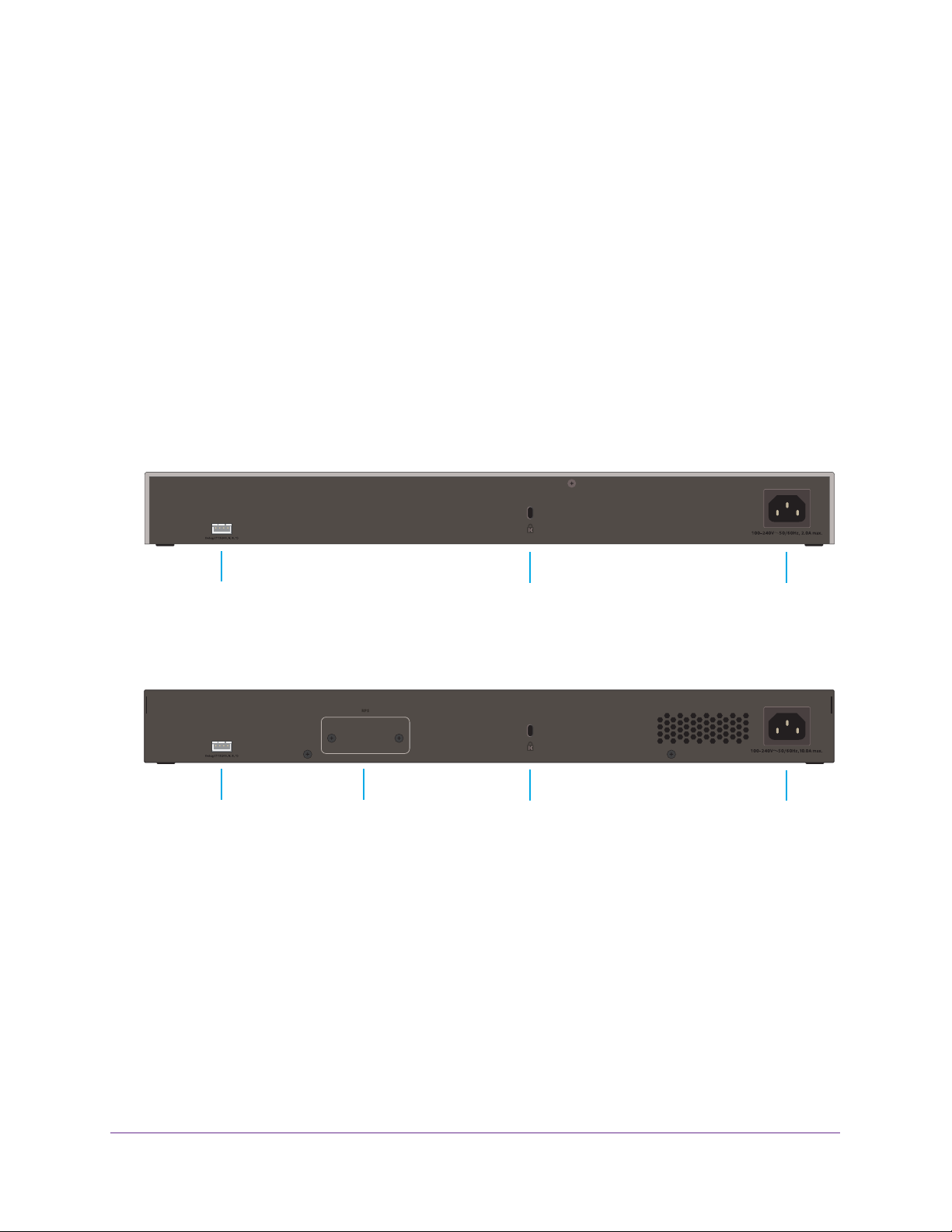
The following figures illustrate the back panel of models S3300-52X and S3300-52X-PoE+:
Console port
Figure 4. Back panel model S3300-52X
Console port
Figure 5. Back panel model S3300-52X-PoE+
RPS slot
Kensington lock
Kensington lock
AC input connector
AC input connector
From left to right, the back panel provides the following components:
• Serial console port that is configured for 115200, N, 8, 1. The serial port is for debugging
purposes by NETGEAR support. (The port requires a special adapter
.)
• Slot for an optional redundant power supply (RPS, model S3300-52X-PoE+ only).
• Kensington lock.
• AC power input connector
.
Physical Description
12
Page 13
S3300 Smart Switch
LED Designations
This section describes the LED designations of models S3300-52X and S3300-52X-PoE+.
Port LEDs
The following table describes the RJ-45 and SFP+ port LED designations.
Table 1. Port LEDs models S3300-52X and S3300-52X-PoE+
LED Designation
Both Models
Left LED
RJ45 SPD Mode LED
(Link, Speed,
copper ports 1 to 48
Link/ACT Mode LED for
10G copper ports
49 and 50
Link/ACT Mode LED for
SFP+ fiber ports
51 and 52
PoE Model Only
Right LED
PoE Mode LED for
copper ports 1 to 48
Activity) for
• Off. No link is established.
• Solid green . A valid 1000 Mbps link is established.
• Blinking green . The port is transmitting or receiving packets at 1000 Mbps.
• Solid yellow . A valid 10/100 Mbps link is established.
• Blinking yellow . The port is transmitting or receiving packets at 10/100 Mbps.
• Off . No link is established on the copper port.
• Solid green . The copper port established a valid 10 Gbps link.
• Blinking green . The copper port is transmitting or receiving packets at
10 Gbps.
• Solid yellow . The copper port established a valid 1 Gbps or 100 Mbps link.
• Blinking yellow . The copper port is transmitting or receiving packets at 1 Gbps
or 100 Mbps.
• Off . No SFP+ module link is established on the fiber port.
• Solid green . The fiber port established a valid 10 Gbps link.
• Blinking green . The fiber port is transmitting or receiving packets at 10 Gbps.
• Solid yellow . The fiber port established a valid 1 Gbps link.
• Blinking yellow . The fiber port is transmitting or receiving packets at 1 Gbps.
• Off. PoE mode is of
• Solid green . PoE mode is on.
• Solid yellow . A PoE fault occurred.
f.
Note: For the non-PoE model, the right LAN LED is nonfunctioning by design.
Physical Description
13
Page 14

S3300 Smart Switch
System LEDs
The following table describes the system LED designations.
Table 2. System LEDs models S3300-52X and S3300-52X-PoE+
LED Designation
Power LED • Off . Power is not supplied to the smart switch.
• Solid green . The smart switch is powered on and operating normally.
• Solid yellow . The smart switch is booting.
Fan LED • Off . The fan is operating normally.
• Solid yellow . The fan failed.
Stack ID LED The Stack ID LED consists of two components, the Segment LED and the Dot LED.
The Segment LED contains seven segments to display the stack unit number of the
smart switch.
provides information about whether the smart switch is the master in the stack.
• Segment LED solid green and Dot LED solid green. This LED status
indicates one
- The smart switch is a standalone switch and is not a member of a stack.
- The smart switch is a member of a stack and is the master of the stack.
• Segment LED solid green and Dot LED off. The
a stack but is not the master of the stack. The Segment LED displays the stack
unit number.
The Dot LED is located at the bottom right of the Stack ID LED and
of the following situations:
Segment LED displays the unit number.
Segment LED displays the stack unit number.
smart switch
The
The
is a member of
PoE Model Only
PoE Max LED • Off . More than 7 watts (W) of PoE power is available for another powered
device (PD).
• Solid yellow . Less than 7 watts (W) of PoE power is available for another PD.
• Blinking yellow . The attached PD was active in the past two minutes.
S3300-28X and S3300-28X-PoE+ Description
This section describes the smart switch hardware features for models S3300-28X and
S3300-28X-PoE+.
S3300-28X Front Panel and Back Panel Configuration
The S3300-28X and S3300-28X-PoE+ models provide twenty four 10/100/1000 Mbps ports,
two dedicated 100M/1G/10GBASE-T, and two dedicated 10G/1G SFP+ ports.
Each port can sense the line speed and negotiate the duplex mode with the link partner
automatically. Model S3300-28X-PoE+ supports PoE+ on ports 1 through 24.
Physical Description
14
Page 15

S3300 Smart Switch
The following figures illustrate the front panel of models S3300-28X and S3300-28X-PoE+.
Power and Fan LEDs
Stack ID LED
Factory Defaults button
Reset button
Figure 6. Front panel model S3300-28X
Power, Fan, and
Max PoE LEDs
Stack ID LED
Left LEDs: RJ45 SPD Mode LED
Left LEDs: RJ45 SPD Mode LED
Right LEDs: nonfunctioning
10/100/1000 Mbps ports
Right LEDs: PoE Mode LED
SFP+ ports
Link/ACT LEDs
10G ports
Link/ACT LEDs
USB port
10G ports
Link/ACT LEDs
10/100/1000 Mbps PoE ports
Factory Defaults button
SFP+ ports
Reset button
Figure 7. Front panel model S3300-28X-PoE+
Link/ACT LEDs
USB port
The front panel provides the following components:
• Twenty four RJ-45 connectors for 10/100/1000 Mbps autosensing Gigabit Ethernet
switching ports
• Two 100M/1G/10GBASE-T copper ports (25–26) that you can also use for stacking
• Two 10G/1G SFP+ fiber ports (27–28) that you can also use for stacking
• One USB 2.0 port that supports FA
T32 and VF
AT file systems
• Reset button to restart the device
• Recessed Factory Defaults button to restore the device back to the factory defaults
• Link, Speed, and
Activity LEDs for each port and for the PoE model, PoE LEDs for
ports 1–24
• Power, Fan, and Stack ID LEDs; for model S3300-28X-PoE+ only, PoE Max LED
Physical Description
15
Page 16

S3300 Smart Switch
The following figures illustrate the back panel of models S3300-28X and S3300-28X-PoE+.
Console port
Figure 8. Back panel model S3300-28X
Console port
Figure 9. Back panel model S3300-28X-PoE+
RPS slot
Kensington lock
Kensington lock
AC input connector
AC input connector
From left to right, the back panel provides the following components:
• Serial console port that is configured for 115200, N, 8, 1. The serial port is for debugging
purposes by NETGEAR support. (The port requires a special adapter
.)
• Slot for an optional redundant power supply (RPS, model S3300-28X-PoE+ only).
• Kensington lock.
• AC power input connector
.
Physical Description
16
Page 17

S3300 Smart Switch
LED Designations
This section describes the LED designations of models S3300-28X and S3300-28X-PoE+.
Port LEDs
The following table describes the RJ-45 and SFP+ port LED designations.
Table 3. Port LEDs models S3300-28X and S3300-28X-PoE+
LED Designation
Both Models
Left LED
RJ45 SPD Mode LED
(Link, Speed,
copper ports 1 to 24
Link/ACT Mode LED for
10G copper ports
26 and 26
Link/ACT Mode LED for
SFP+ fiber ports
27 and 28
PoE Model Only
Right LED
PoE Mode LED for
copper ports 1 to 24
Activity) for
• Off. No link is established.
• Solid green . A valid 1000 Mbps link is established.
• Blinking green . The port is transmitting or receiving packets at 1000 Mbps.
• Solid yellow . A valid 10/100 Mbps link is established.
• Blinking yellow . The port is transmitting or receiving packets at 10/100 Mbps.
• Off . No link is established on the copper port.
• Solid green . The copper port established a valid 10 Gbps link.
• Blinking green . The copper port is transmitting or receiving packets at
10 Gbps.
• Solid yellow . The copper port established a valid 1 Gbps or 100 Mbps link.
• Blinking yellow . The copper port is transmitting or receiving packets at 1 Gbps
or 100 Mbps.
• Off . No SFP+ module link is established on the fiber port.
• Solid green . The fiber port established a valid 10 Gbps link.
• Blinking green . The fiber port is transmitting or receiving packets at 10 Gbps.
• Solid yellow . The fiber port established a valid 1 Gbps link.
• Blinking yellow . The fiber port is transmitting or receiving packets at 1 Gbps.
• Off. PoE mode is of
• Solid green . PoE mode is on.
• Solid yellow . A PoE fault occurred.
f.
Note: For the non-PoE model, the right LAN LED is non-functioning by design.
Physical Description
17
Page 18

S3300 Smart Switch
System LEDs
The following table describes the system LED designations.
Table 4. System LEDs models S3300-28X and S3300-28X-PoE+
LED Designation
Power LED • Off . Power is not supplied to the smart switch.
• Solid green . The smart switch is powered on and operating normally.
• Solid yellow . The smart switch is booting.
Fan LED • Off . The fan is operating normally.
• Solid yellow . The fan failed.
Stack ID LED The Stack ID LED consists of two components, the Segment LED and the Dot LED.
The Segment LED contains seven segments to display the stack unit number of the
smart switch.
provides information about whether the smart switch is the master in the stack.
• Segment LED solid green and Dot LED solid green. This LED status
indicates one
- The smart switch is a standalone switch and is not a member of a stack.
- The smart switch is a member of a stack and is the master of the stack.
• Segment LED solid green and Dot LED off. The
a stack but is not the master of the stack. The Segment LED displays the stack
unit number.
The Dot LED is located at the bottom right of the Stack ID LED and
of the following situations:
Segment LED displays the unit number.
Segment LED displays the stack unit number.
smart switch
The
The
is a member of
PoE Model Only
PoE Max LED • Off . More than 7 watts (W) of PoE power is available for another powered
device (PD).
• Solid yellow . Less than 7 watts (W) of PoE power is available for another PD.
• Blinking yellow . The attached PD was active in the past two minutes.
Device Hardware Interfaces
This section describes the hardware interfaces of the S3300 models.
RJ-45 Ports
The RJ-45 ports are autosensing ports. When you insert a cable into an RJ-45 port, the smart
switch automatically ascertains the maximum speed (10 Mbps, 100 Mbps, 1 Gbps, or 10
Gbps) and duplex mode (half-duplex or full-duplex) of the attached device. All ports support
only an unshielded twisted-pair (UTP) cable terminated with an 8-pin RJ-45 plug.
To simplify the procedure for attaching devices, all RJ-45 ports support Auto Uplink
technology. This technology allows attaching devices to the RJ-45 ports with either
straight-through or crossover cables.
Physical Description
18
Page 19

S3300 Smart Switch
When you insert a cable into the smart switch’s RJ-45 port, the smart switch automatically
performs the following actions:
• Senses whether the cable is a straight-through or crossover cable.
• Determines whether the link to the attached device requires a normal connection (such
as when you are connecting the port to a computer) or an uplink connection (such as
when you are connecting the port to a router, switch, or hub).
• Automatically configures the RJ-45 port to enable communications with the attached
device. The
eliminating concern about whether to use crossover or straight-through cables when you
attach devices.
Auto Uplink technology compensates for setting uplink connections while
10GBASE-T Ports
To enable high-speed copper and long distance connections on the smart switch, two RJ-45
10GBASE-T copper ports (the two ports to the left of the SFP+ ports on the front panel)
support speeds of up to 10 Gbps.
You can also use the 10GBASE-T ports to connect the smart switch to a stack.
SFP+ Ports
To enable high-speed fiber and long distance connections on the smart switch, two SFP+
fiber ports (the rightmost two ports on the front panel) accommodate standard 10G and
1G SFP+ transceiver modules, which are sold separately.
You can also use the SFP+ ports to connect the smart switch to a stack.
Reset Button
The smart switch provides a Reset button on the front panel to allow you to manually reboot
the smart switch. This action is equivalent to powering the unit off and back on. The last
saved configuration is loaded into the smart switch as it resets.
To reset the smart switch using the Reset button:
1. Insert a device such as a straightened paper clip into the opening.
2. Press the recessed Reset button for a short time (less than two seconds).
The front panel LEDs turn off and light again when the smart switch performs its
power-on self-test (POST).
Factory Defaults Button
The smart switch provides a Factory Defaults button on the front panel so that you can
remove the current configuration and return the device to its factory settings. When you press
the Factory Defaults button, all custom settings including the password, VLAN settings, and
port configurations are returned to default values.
Physical Description
19
Page 20

S3300 Smart Switch
T o reset the smart switch to factory default settings using the Factory Defaults button:
1. Insert a device such as a straightened paper clip into the opening.
2. Press the recessed Factory Defaults button for about eight seconds.
Note: A smart switch that is a member of a stack retains its stacking
configuration.
USB Port
The smart switch provides one USB 2.0 port to upgrade firmware from a disk, back up the
configuration to a storage device, and allow for the collection of a memory dump for
debugging purposes.
A device that you attach to the USB port must comply with the following requirements:
• The USB device must support USB 2.0.
• The USB device must support the FA
supported.
T32 or VFAT file type. The NTFS file type is not
Because of hardware limitations, the write and read speed to and from a USB device is about
1 Mbps.
Note: In a stack, only the smart switch that functions as the master can
detect and manage an attached USB device.
PoE Ports
The PoE power budgets for model S3300-52X-PoE+ and model S3300-28X-PoE+ differ.
Model S3300-52X-PoE+
Model S3300-52X-PoE+ supports PoE+ on ports 1 through 48. The total power budget
depends on the power supply configuration:
• 390W with the internal power supply only
• 1440W with either the redundant power supply (RPS) only or with both the internal power
supply and the RPS
Model S3300-28X-PoE+
Model S3300-28X-PoE+ supports PoE+ on ports 1 through 24. The total power budget
depends on the power supply configuration:
• 195W with the internal power supply only
• 720W with either the redundant power supply (RPS) only or with both the internal power
supply and the RPS
Physical Description
20
Page 21

3. Desktop and Backbone Switching
3
The S3300 Smart Switch is designed to provide flexibility in configuring your network
connections. You can use the smart switch as your only network traffic distribution device or with
10 Mbps, 100 Mbps, 1000 Mbps, and 10 Gbps hubs and switches.
The chapter includes the following sections:
• Desktop Switching
• Backbone Switching
21
Page 22

S3300 Smart Switch
Desktop Switching
You can use the smart switch as a desktop switch to build a small network that allows users
1000 Mbps access to, for example, a file server. With full duplex enabled, the smart switch
port connected to the server or computer can provide 2000 Mbps throughput. If you use a
10 Gbps module to connect the smart switch to the file server in full-duplex operation, the
server can provide up to 20 Gbps throughput.
The following figure shows model S3300-28X-PoE+. However, you can use any of the other
S3300 models for desktop switching.
Figure 10. Desktop switching
Desktop and Backbone Switching
22
Page 23

S3300 Smart Switch
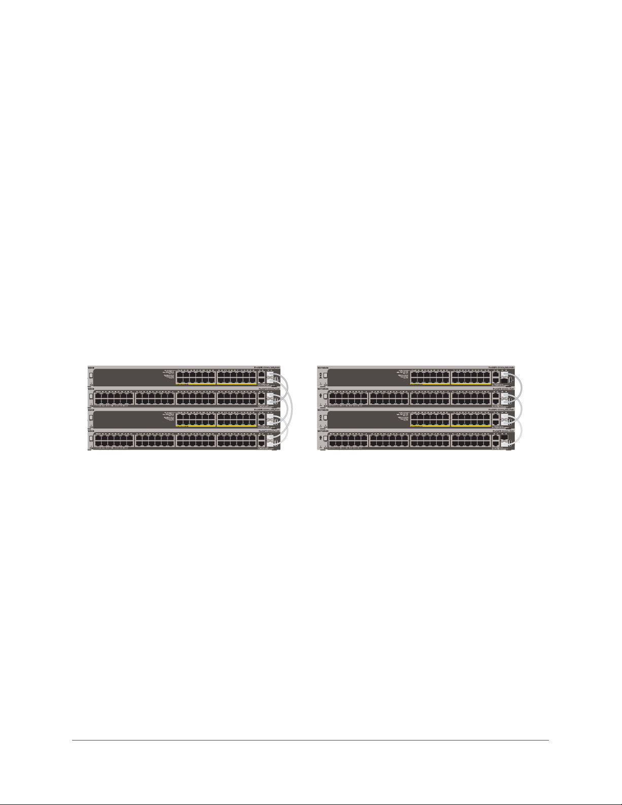
Backbone Switching
You can use the smart switch as a backbone switch in a small network that gives users
high-speed access to servers and other network devices.
The following figure shows a variety of S3300 models. You can use any of the S3300 models
for backbone switching.
Internet
Figure 11. Backbone switching
Desktop and Backbone Switching
23
Page 24

4. Installation
This chapter describes the installation procedures for the S3300 Smart Switch. Switch
installation involves the steps described in the following sections:
Step 1: Prepare the Site
Step 2: Install the Switch
Step 3: Check the Installation
Step 4: Connect Devices to the Switch
Step 5: Install an SFP Transceiver Module
Step 6: Install the Smart Switch as a Stack Master or Stack Slave
Step 7: Apply AC Power
Step 8: Install the RPS and Apply RPS DC Power
Step 9: Manage the Switch Through a Web Browser or the Smart Control Center Utility
4
24
Page 25

S3300 Smart Switch
Step 1: Prepare the Site
Before you install the smart switch, ensure that the operating environment meets the site
requirements that are listed in the following table.
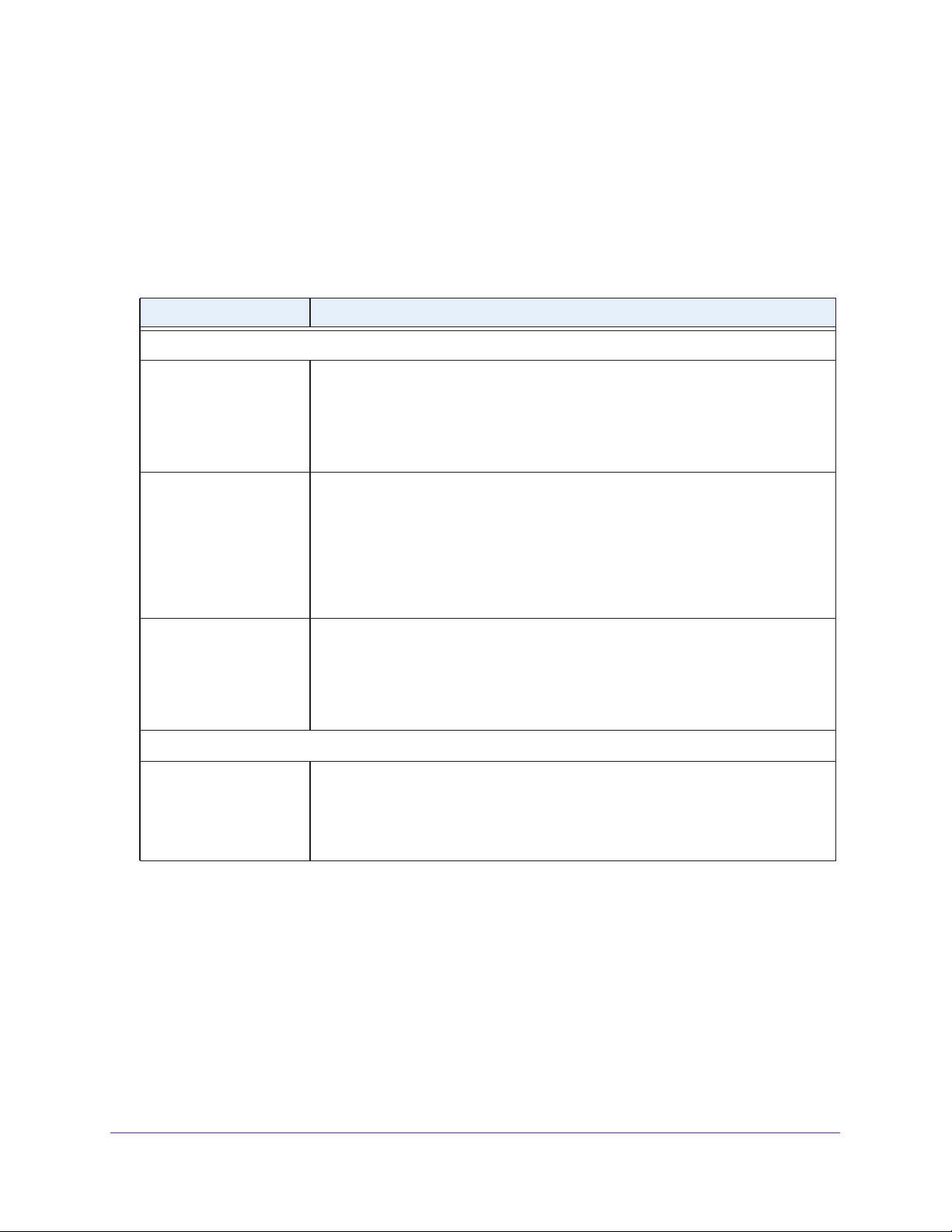
Table 5. Site requirements
Characteristics Requirements
Mounting • Desktop installations. Provide a flat table or shelf surface.
• Rack-mount installations. Use a 19-inch (48.3-centimeter) EIA standard equipment
rack that is grounded and physically secure.
supplied with the smart switch.
Access Locate the smart switch in a position that allows you to access the front panel RJ-45 ports,
view the front panel LEDs, and access the power connector on the back panel.
You also need the rack-mount kit that is
Power source Use the
specifications, see Appendix B, Physical and Technical Specifications.
Ensure that the AC outlet is not controlled by a wall switch, which can accidentally turn off
power to the outlet and the smart switch.
Environmental • T
• Operating humidity. The
• V
• Operating conditions. Keep the smart switch at least 6 feet (1.83 meters) away from
AC power cord that is supplied with the smart switch. For information about power
emperature. Install the smart switch in a dry area with an ambient temperature
between 0ºC and 50ºC (32ºF and 122ºF). Keep the smart switch away from heat sources
such as direct sunlight, warm-air exhausts, hot-air vents, and heaters.
maximum relative
exceed 90%, noncondensing.
entilation. Do not restrict airflow by covering or obstructing air inlets on the sides of the
smart switch. Keep at least 2 inches (5.08 centimeters) free on all sides for cooling. The
room or wiring closet in which you install the smart switch must provide adequate airflow
the nearest source of electromagnetic noise, such as a photocopy machine.
humidity of the installation location must not
Step 2: Install the Switch
You can install the smart switch on a flat surface or mount it in a standard network equipment
rack.
Install the Switch on a Flat Surface
.
The smart switch ships with four self-adhesive rubber footpads.
To install the smart switch on a flat surface:
Stick one rubber footpad on each of the four concave spaces on the bottom of the smart
switch.
The rubber footpads cushion the smart switch against shock and vibrations. They also
provide ventilation space between stacked switches.
Installation
25
Page 26
S3300 Smart Switch
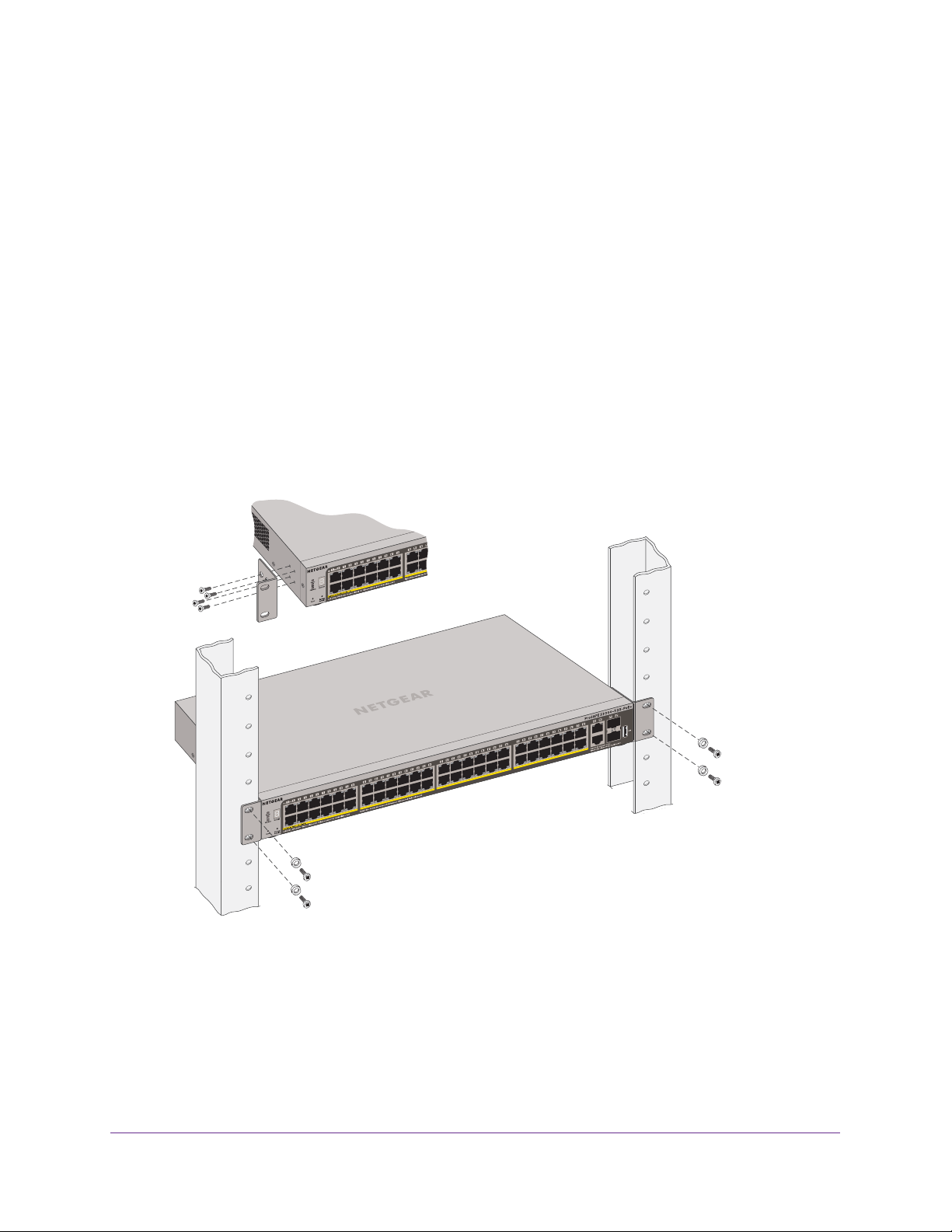
Install the Switch in a Rack
To install the smart switch in a rack, you need the 19-inch rack-mount kit supplied with the
smart switch.
To install the smart switch in a rack:
1. Attach the supplied mounting brackets to the side of the smart switch.
2. Insert the screws provided in the rack-mount kit through each bracket and into the bracket
mounting holes in the smart switch.
3. Tighten the screws with a No. 1 Phillips screwdriver to secure each bracket.
4. Align the mounting holes in the brackets with the holes in the rack, and insert two pan-head
screws with nylon washers through each bracket and into the rack.
5. T
ighten the screws with a No. 2 Phillips screwdriver to secure mounting brackets to the rack.
The following figure shows model S3300-52X-PoE+. However, you install the other S3300
models in the same manner.
Installation
26
Page 27

S3300 Smart Switch
Step 3: Check the Installation
Before you apply power to the smart switch, perform the steps that are described in this
section.
To check the installation:
1. Inspect the equipment thoroughly.
2. Verify that all cables are installed correctly.
3. Check cable routing to make sure that cables are not damaged or creating a safety hazard.
4. Ensure that all equipment is mounted properly and securely
.
Step 4: Connect Devices to the Switch
The following procedure describes how to connect computers to the smart switch’s RJ-45
ports. The smart switch supports Auto Uplink technology, which allows you attach devices
using either straight-through or crossover cables.
The following figure shows model S3300-28X-PoE+. However, the other S3300 models are
connected in the same manner.
Figure 12. Connecting devices to the smart switch
Note: Ethernet specifications limit the cable length between the smart
switch and the attached device to 100 meters (328 feet).
To connect devices to the smart switch:
Using a Category 5 (Cat 5) unshielded twisted-pair (UTP) cable terminated with an RJ-45
connector, connect each computer to an RJ-45 network port on the smart switch front panel.
Installation
27
Page 28
S3300 Smart Switch
Note: For 10GBASE-T connections, and in particular for connections over
30 meters (about 100 feet), NETGEAR recommends that you use a
Category 6a cable or a cable that is even higher rated.
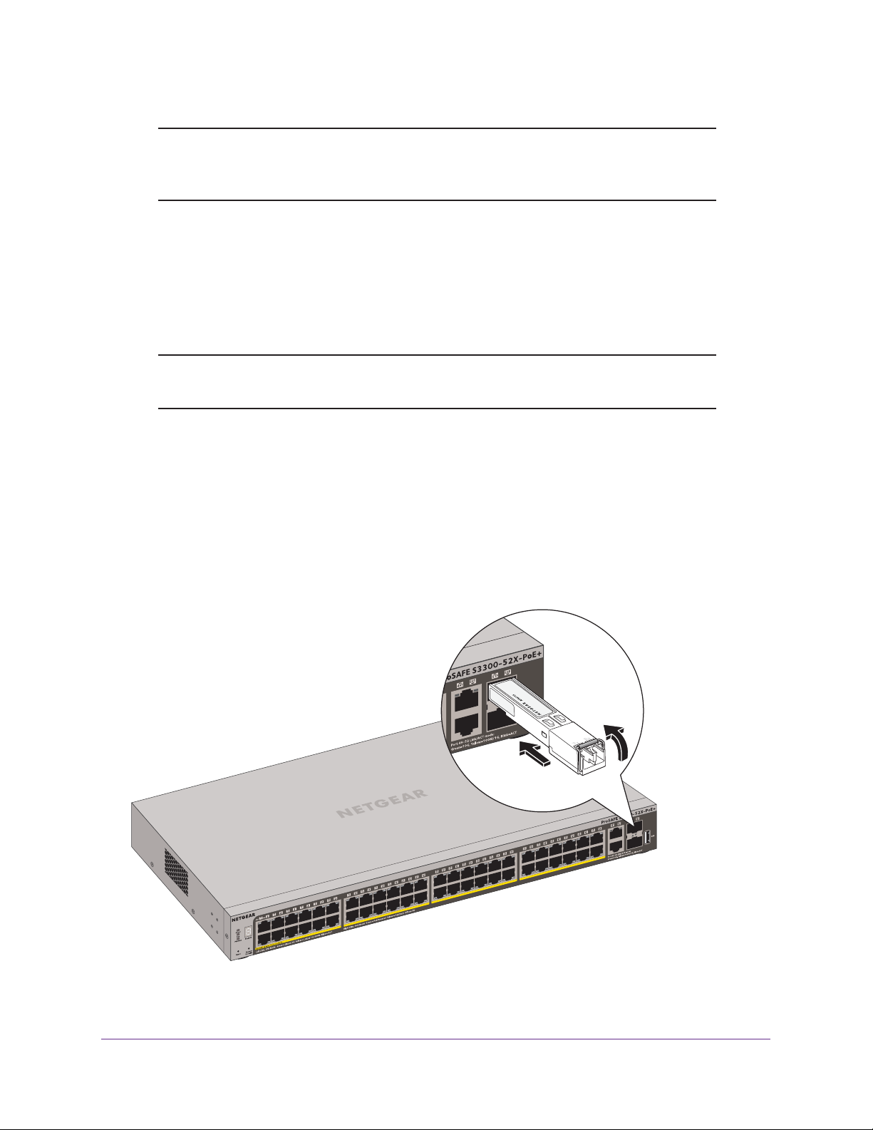
Step 5: Install an SFP Transceiver Module
The following procedure describes how to install an optional SFP transceiver module into one
of the SFP ports of the smart switch.
Note: Contact your NETGEAR sales office to buy these modules. If you do
not want to install an SFP module, skip this procedure.
To install an SFP transceiver module:
1. Insert the transceiver into the SFP port.
2. Press firmly on the flange of the module to seat it securely into the connector
You can install up to two additional 10 Gbps or 1 Gbps modules using this procedure.
The following figure shows model S3300-52X-PoE+. However
modules in the other S3300 models in the same manner.
, you install SFP transceiver
.
Figure 13. Installing an SFP transceiver module
Installation
28
Page 29
S3300 Smart Switch
Step 6: Install the Smart Switch as a Stack Master or Stack Slave
The smart switch can function as a master, backup master, or slave in a stack. (For more
information about stacking, see Stacking on page 8.)
A backup master runs as a slave. In addition, it continuously monitors the existence and
operation of the master. If the master fails, the backup master assumes the role of the master
through a switchover. In the default configuration, the master and backup master are
assigned unit ID 1 and 2, respectively . However, you can use the web management interface
to assign different unit IDs. The goal for switchover time is less than 30 seconds.
If a stacking cable fails or a stack member is extracted in a chain topology, slaves could be
disconnected from the stack (which puts them in an ambiguous state), causing all their ports
to enter the down state.
Each stack member can work in one of two modes: slave mode or master mode. The
operational mode is determined at software boot time and can be changed only by a unit
reset.
The Segment Stack ID LED remains lit in both modes.
The smart switch supports two stacking topologies: ring topology and chain topology.
Ring topology
Figure 14. Stacking topologies
The smart switch is a plug-and-play device in terms of setting up a stacking configuration.
Before powering up the smart switch, connect the devices into the required stacking
topology . Then power up the smart switch and the other devices. By default, the smart switch
is configured to allow the master and slave designations to be determined through automatic
discovery . After the smart switch boots and is operational, you can use the web management
interface to configure the stack to select a particular switch as master.
For more information about stacking, see the S3300 Smart Switch Software
Manual.
The resource CD includes a link to this document.
Chain topology
Administration
Step 7: Apply AC Power
The smart switch does not provide an on/off switch. The power cord connection controls the
power.
Before connecting the power cord, select an AC outlet that is not controlled by a wall switch,
which can turn off power to the smart switch.
Installation
29
Page 30

S3300 Smart Switch
To apply AC power:
1. Connect the end of the power cord to the power receptacle on the back of the smart
switch.
2. Plug the AC
When you apply power, the Power LED on the smart switch’s front panel lights.
If the Power LED does not light, check that the power cord is plugged in correctly and that the
power source is good. If the problem remains, see Appendix A, Troubleshooting.
power cord into a power source such as a wall socket or power strip.
Step 8: Install the RPS and Apply RPS DC Power
This step is optional for models S3300-52X-PoE+ and S3300-28X-PoE+ only. These models
support an optional external redundant power supply (RPS).
To install the RPS and apply RPS DC power:
1. Loosen the screws of the RPS cover plate and remove the cover plate.
The RPS receptacle is exposed.
2. Plug in the RPS connector
3. Plug the AC
strip.
power cord of the RPS into a power source such as a wall socket or power
.
Step 9: Manage the Switch Through a Web Browser or the Smart Control Center Utility
The smart switch contains software for viewing, changing, and monitoring the way it works.
This management software is not required for the smart switch to work. You can use the
ports without using the management software. However, the management software enables
the setup of VLAN and trunking features and also improves the efficiency of the smart switch,
which results in the improvement of its overall performance as well as the performance of the
network.
After you power up the smart switch for the first time, you can configure the smart switch
using a web browser or a program called Smart Control Center. For more information about
managing the smart switch, see the S3300 Smart Switch Software
The resource CD includes a link to this document.
Administration Manual
.
Note: The smart switch is configured with a default IP address of
192.168.0.239 and a subnet mask of 255.255.255.0.
Installation
30
Page 31

A. Troubleshooting
This appendix provides information about troubleshooting the S3300 Smart Switch.
The appendix includes the following sections:
• Troubleshooting Chart
• Additional Troubleshooting Suggestions
A
31
Page 32

S3300 Smart Switch
Troubleshooting Chart
The following table lists symptoms, causes, and solutions for possible problems.
Table 6. Troubleshooting chart
Symptom Cause Solution
Power LED is off. No power is received. • Check the power cord connections at the
smart switch and the power source.
• Ensure that all cables are used correctly and
comply with the Ethernet specifications.
Combined Link, Speed,
Activity LED is of
the port is connected to
a device.
File transfer is slow or
performance is
degraded.
A segment or device is
not recognized as part
of the network.
Combined Link, Speed,
Activity LED is blinking
continuously on all
connected ports and
the network is disabled.
f when
Port connection is not working. • Check the crimp on the connectors and
make sure that the plug is properly inserted
and locked into the port at both the smart
switch and the connecting device.
• Ensure that all cables are used correctly and
comply with the Ethernet specifications.
• Check for a defective port, cable, or module
by testing them in an alternate environment
where all products are functioning.
Half-duplex or full-duplex setting on
the smart switch and the connected
device are not the same.
One or more devices are not
properly connected, or cabling does
not meet Ethernet guidelines.
A network loop (redundant path)
was created.
Make sure that the attached device is configured
to autonegotiate.
• V
erify that the cabling is correct.
• Ensure that all connectors are securely
positioned in the required ports. It is possible
that equipment was accidentally
disconnected.
Break the loop by ensuring that only one path
exists from any networked device to any other
networked device.
switch web management interface, you can
configure the Spanning
prevent network loops.
After you connect to the smart
ree Protocol (STP) to
T
A unit is linked to a
stack but does not join
the stack.
The stacking ports of the new unit
are configured dif
stack, or the unit is configured as a
standalone unit.
ferently from the
Troubleshooting
32
Remove the unit from the stack. Use the web
management interface to configure the unit as a
stackable unit, with combo links used as the
stacking ports.
Page 33

S3300 Smart Switch
Additional Troubleshooting Suggestions
If the suggestions in the troubleshooting chart do not resolve the problem, see the following
troubleshooting suggestions:
• Network Adapter Cards. Ensure that the network adapter cards installed in the
computers are in working condition and the software driver was installed.
• Configuration. If problems occur after you alter the network configuration, restore the
original connections and determine the problem by implementing the new changes, one
step at a time. Ensure that cable distances, repeater limits, and other physical aspects of
the installation do not exceed the Ethernet limitations.
• Switch Integrity. If necessary
reset the smart switch, disconnect the AC power from the smart switch and then
reconnect the AC power. If the problem continues, contact NETGEAR technical support:
- Phone (US & Canada only): 1-888-NETGEAR.
- Phone (other countries): Check the list of phone numbers at
http://support.netgear.com/general/contact/default.aspx.
• Autonegotiation.
control if the device at the other end of the link supports autonegotiation. If the device
does not support autonegotiation, the smart switch determines only the speed correctly
and the duplex mode defaults to half-duplex.
The RJ-45 ports negotiate the correct duplex mode, speed, and flow
, verify the integrity of the smart switch by resetting it.
To
,
The Gigabit Ethernet ports negotiate speed, duplex mode, and flow control if the attached
device supports autonegotiation.
Troubleshooting
33
Page 34

B. Physical and Technical Specifications
This appendix provides the physical and technical specifications for the S3300 Smart Switch.
Table 7. Physical and technical specifications
Feature Description
B
Network protocols and
supported standards
Interfaces • S3300-52X and S3300-52X-PoE+: forty eight 10/100/1000 Mbps ports
LEDs • Combined Link, Speed,
Memory • SRAM size and type: 256 MB DDR3 SDRAM
• IEEE 802.3i (10BASE-T)
• IEEE 802.3u (100BASE-TX)
• IEEE 802.3ab (1000BASE-T)
• IEEE 802.3an (10GBASE-T)
• IEEE 802.3z (1000BASE-X)
• IEEE 802.3 Clause 49 (10GBASE-LR and 10GBASE-SR)
• IEEE802.aq (10GBASE-LRM)
• IEEE802.3ae (10GBASE Ethernet)
• IEEE802.3az (Energy Ef
• IEEE 802.3x (Full-duplex flow control)
• IEEE 802.1at (PoE+)
• S3300-28X and S3300-28X-PoE+: twenty four 10/100/1000 Mbps ports
• T
wo 100M/1G/10GBASE-T ports
• Two 10G/1G SFP+ ports
• One USB port
• PoE LED for each PoE port (S3300-52X-PoE+ and S3300-28X-PoE+)
• Power
• PoE Max system LED (S3300-52X-PoE+ and S3300-28X-PoE+)
• Flash memory size: 64 MB SPI Flash
, Fan, and Stack ID system LEDs
ficient Ethernet)
Activity LED for each port
34
Page 35

S3300 Smart Switch
Table 7. Physical and technical specifications (continued)
Feature Description
Performance and capacity • Forwarding mode: Store and Forward
• Stacking for up to six switches
• Bandwidth:
- S3300-52X/S3300-52X-PoE+ models: 176 Gbps
- S3300-28X/S3300-28X-PoE+ models: 128 Gbps
• Address database size: 16K Media
• Mean Time
- S3300-52X: 279,970 hours
- S3300-52X-PoE+: 216,809 hours
- S3300-28X: 278,559 hours
- S3300-28X-PoE+: 147,965 hours
Between Failure (MTBF) at 25°C:
Access Control (MAC) addresses
AC power supply • Universal power input: 100–240 V
• Current:
- S3300-52X: 2A
- S3300-52X-PoE+: 10A
- S3300-28X: 1.5A
- S3300-28X-PoE+: 4A
Redundant power supply • S3300-52X-PoE+: DC1
• S3300-28X-PoE+: DC11V
PoE power budget • S3300-52X-PoE+:
- 390W with internal power supply only
- 1440W with external RPS only
- 1440W with both internal power supply and external RPS
• S3300-28X-PoE+:
- 195W with internal power supply only
- 720W with external RPS only
- 720W with both internal power supply and external RPS
Physical specifications • S3300-52X
- Dimensions (H x W x D): 43 x 440 x 257 mm (1.7 x 17.3 x 10.1 in.)
- W
eight: 3.66 kg (8.0 lb)
• S3300-52X-PoE+
- Dimensions (H x W x D): 43 x 440 x 345 mm ((1.7 x 17.3 x 13.6 in.)
- W
eight: 5.54 kg (12.2 lb)
• S3300-28X
- Dimensions (H x W x D): 43 x 440 x 257 mm (1.7 x 17.3 x 10.1 in.)
- W
eight: 3.14 kg (6.9 lb)
• S3300-28X-PoE+
- Dimensions (H x W x D): 43 x 440 x 257 mm (1.7 x 17.3 x 10.1 in.)
- W
eight: 3.77 kg (8.3 lb)
1V
, 13.5A maximum; DC56V, 28.2A maximum
, 6.5A maximum; DC56V, 14.1A maximum
AC, 50–60 Hz
Physical and Technical Specifications
35
Page 36

S3300 Smart Switch
Table 7. Physical and technical specifications (continued)
Feature Description
Environmental specifications • Operating temperature: 0 to 50°C (32 to 122°F)
• Storage temperature: –20 to 70°C (28 to 158°F)
• Operating humidity: 10–90% maximum relative humidity
• Storage humidity: 5–95% maximum relative humidity, noncondensing
Electromagnetic emissions • CE mark, commercial
• FCC Part 15 Class
• VCCI Class A
• CISPR 22 Class A (Australia)
• CCC
• KCC
• CAN ICES-3(A)/NMB-3(A)
• EN 55022 Class
• BSMI 13438
A
A
, noncondensing
Electromagnetic immunity EN 55024, Class
Safety certifications • UL/cUL/CE EN 60950-1
• CB
• CCC
• BSMI 14336
• CU (Russia)
• SAI (Australia/NZ)
A
Physical and Technical Specifications
36
 Loading...