

Page 1

S3300 Smart Managed Pro Switch
User Manual
Firmware Version 6.6.4
September 2017
202-11377-03
350 East Plumeria Drive
San Jose, CA 95134
USA
Page 2

S3300 Smart Managed Pro Switch
Support
Thank you for purchasing this NETGEAR product. You can visit www.netgear.com/support to register your product, get help,
access the latest downloads and user manuals, and join our community. We recommend that you use only official NETGEAR
support
resources.
Conformity
For the current EU Declaration of Conformity, visit http://kb.netgear.com/app/answers/detail/a_id/11621.
Compliance
For regulatory compliance information, visit http://www.netgear.com/about/regulatory.
See the regulatory compliance document before connecting the power supply.
Trademarks
© NETGEAR, Inc., NETGEAR, and the NETGEAR Logo are trademarks of NETGEAR, Inc. Any non-NETGEAR trademarks are
used for reference purposes only.
Revision History
Publication Part Number Publish Date Comments
202-11377-01 July 2014 First publication
202-11377-02 June 2016 Updated manual to conform to firmware release v6.6.0.x.
202-11377-03 September 2017 Updated manual for release 6.6.4.
2
Page 3

Contents
Chapter 1 Getting Started
Getting Started with the NETGEAR Switch. . . . . . . . . . . . . . . . . . . . . . . . . . . . . . 11
Switch Management Interface . . . . . . . . . . . . . . . . . . . . . . . . . . . . . . . . . . . . . . . . 12
Connect the Switch to the Network . . . . . . . . . . . . . . . . . . . . . . . . . . . . . . . . . . . 13
Discover a Switch in a Network with a DHCP Server . . . . . . . . . . . . . . . . . . . . . 14
Discover a Switch in a Network without a DHCP Server . . . . . . . . . . . . . . . . . . 16
Configure the Network Settings on the Administrative System . . . . . . . . . . . . 17
Access the Management Interface from a Web Browser . . . . . . . . . . . . . . . . . . 21
Understand the User Interfaces . . . . . . . . . . . . . . . . . . . . . . . . . . . . . . . . . . . . . . . 21
Use the Web Interface . . . . . . . . . . . . . . . . . . . . . . . . . . . . . . . . . . . . . . . . . . . . . 21
Use SNMPv3 . . . . . . . . . . . . . . . . . . . . . . . . . . . . . . . . . . . . . . . . . . . . . . . . . . . . . 29
Interface Naming Convention . . . . . . . . . . . . . . . . . . . . . . . . . . . . . . . . . . . . . . . . . 30
Configuring Interface Settings . . . . . . . . . . . . . . . . . . . . . . . . . . . . . . . . . . . . . . . . 32
Online Help . . . . . . . . . . . . . . . . . . . . . . . . . . . . . . . . . . . . . . . . . . . . . . . . . . . . . . . . . 36
Support. . . . . . . . . . . . . . . . . . . . . . . . . . . . . . . . . . . . . . . . . . . . . . . . . . . . . . . . . . 36
User Guide . . . . . . . . . . . . . . . . . . . . . . . . . . . . . . . . . . . . . . . . . . . . . . . . . . . . . . . 36
Registration . . . . . . . . . . . . . . . . . . . . . . . . . . . . . . . . . . . . . . . . . . . . . . . . . . . . . . . . 37
Chapter 2 Configure System Information
Management . . . . . . . . . . . . . . . . . . . . . . . . . . . . . . . . . . . . . . . . . . . . . . . . . . . . . . . 39
System Information . . . . . . . . . . . . . . . . . . . . . . . . . . . . . . . . . . . . . . . . . . . . . . . 39
System CPU Status. . . . . . . . . . . . . . . . . . . . . . . . . . . . . . . . . . . . . . . . . . . . . . . . 43
USB Device Information. . . . . . . . . . . . . . . . . . . . . . . . . . . . . . . . . . . . . . . . . . . . 45
Slot Information . . . . . . . . . . . . . . . . . . . . . . . . . . . . . . . . . . . . . . . . . . . . . . . . . . 47
IP Configuration . . . . . . . . . . . . . . . . . . . . . . . . . . . . . . . . . . . . . . . . . . . . . . . . . . 48
IPv6 Network Configuration. . . . . . . . . . . . . . . . . . . . . . . . . . . . . . . . . . . . . . . . 50
IPv6 Network Neighbor. . . . . . . . . . . . . . . . . . . . . . . . . . . . . . . . . . . . . . . . . . . . 52
Time . . . . . . . . . . . . . . . . . . . . . . . . . . . . . . . . . . . . . . . . . . . . . . . . . . . . . . . . . . . . 53
Denial of Service. . . . . . . . . . . . . . . . . . . . . . . . . . . . . . . . . . . . . . . . . . . . . . . . . . 61
DNS . . . . . . . . . . . . . . . . . . . . . . . . . . . . . . . . . . . . . . . . . . . . . . . . . . . . . . . . . . . . . 64
Green Ethernet . . . . . . . . . . . . . . . . . . . . . . . . . . . . . . . . . . . . . . . . . . . . . . . . . . . 67
License . . . . . . . . . . . . . . . . . . . . . . . . . . . . . . . . . . . . . . . . . . . . . . . . . . . . . . . . . . . . 76
Switch Stack Configuration . . . . . . . . . . . . . . . . . . . . . . . . . . . . . . . . . . . . . . . . . . . 77
Stacking Overview . . . . . . . . . . . . . . . . . . . . . . . . . . . . . . . . . . . . . . . . . . . . . . . . 77
Smart M4300/S3300 Stacking Notes and Restrictions . . . . . . . . . . . . . . . . 79
Basic Stack Configuration . . . . . . . . . . . . . . . . . . . . . . . . . . . . . . . . . . . . . . . . . . 80
Advanced Stack Configuration . . . . . . . . . . . . . . . . . . . . . . . . . . . . . . . . . . . . . . 83
Advanced Stack Status . . . . . . . . . . . . . . . . . . . . . . . . . . . . . . . . . . . . . . . . . . . . 83
Advanced Stack-Port Configuration . . . . . . . . . . . . . . . . . . . . . . . . . . . . . . . . . 85
3
Page 4

S3300 Smart Managed Pro Switch
Advanced Stack-Port Diagnostics . . . . . . . . . . . . . . . . . . . . . . . . . . . . . . . . . . . 86
Multiple Stack Links . . . . . . . . . . . . . . . . . . . . . . . . . . . . . . . . . . . . . . . . . . . . . . . . . 88
PoE. . . . . . . . . . . . . . . . . . . . . . . . . . . . . . . . . . . . . . . . . . . . . . . . . . . . . . . . . . . . . . . . 90
Advanced PoE Configuration . . . . . . . . . . . . . . . . . . . . . . . . . . . . . . . . . . . . . . . 91
Advanced PoE Port Configuration . . . . . . . . . . . . . . . . . . . . . . . . . . . . . . . . . . . 91
SNMP . . . . . . . . . . . . . . . . . . . . . . . . . . . . . . . . . . . . . . . . . . . . . . . . . . . . . . . . . . . . . 95
Configure the SNMPv1/v2 Community . . . . . . . . . . . . . . . . . . . . . . . . . . . . . . 95
LLDP . . . . . . . . . . . . . . . . . . . . . . . . . . . . . . . . . . . . . . . . . . . . . . . . . . . . . . . . . . . . . . 98
LLDP Configuration . . . . . . . . . . . . . . . . . . . . . . . . . . . . . . . . . . . . . . . . . . . . . . . 99
LLDP Port Settings . . . . . . . . . . . . . . . . . . . . . . . . . . . . . . . . . . . . . . . . . . . . . . . 100
LLDP-MED Network Policy. . . . . . . . . . . . . . . . . . . . . . . . . . . . . . . . . . . . . . . . 101
LLDP-MED Port Settings. . . . . . . . . . . . . . . . . . . . . . . . . . . . . . . . . . . . . . . . . . 102
LLDP-MED Neighbors Information . . . . . . . . . . . . . . . . . . . . . . . . . . . . . . . . . 103
Local Information . . . . . . . . . . . . . . . . . . . . . . . . . . . . . . . . . . . . . . . . . . . . . . . . 106
Neighbors Information. . . . . . . . . . . . . . . . . . . . . . . . . . . . . . . . . . . . . . . . . . . . 110
Services. . . . . . . . . . . . . . . . . . . . . . . . . . . . . . . . . . . . . . . . . . . . . . . . . . . . . . . . . . . 113
DHCP L2 Relay . . . . . . . . . . . . . . . . . . . . . . . . . . . . . . . . . . . . . . . . . . . . . . . . . . 113
DHCP Snooping. . . . . . . . . . . . . . . . . . . . . . . . . . . . . . . . . . . . . . . . . . . . . . . . . . 116
DHCP Snooping Statistics . . . . . . . . . . . . . . . . . . . . . . . . . . . . . . . . . . . . . . . . . 121
DHCPv6 Snooping . . . . . . . . . . . . . . . . . . . . . . . . . . . . . . . . . . . . . . . . . . . . . . . 122
DHCPv6 Snooping Statistics . . . . . . . . . . . . . . . . . . . . . . . . . . . . . . . . . . . . . . . 125
Dynamic ARP Inspection . . . . . . . . . . . . . . . . . . . . . . . . . . . . . . . . . . . . . . . . . . 126
Timer Schedule . . . . . . . . . . . . . . . . . . . . . . . . . . . . . . . . . . . . . . . . . . . . . . . . . . . . 132
Define a Timer Schedule Name. . . . . . . . . . . . . . . . . . . . . . . . . . . . . . . . . . . . . 132
Configure Timer Schedule. . . . . . . . . . . . . . . . . . . . . . . . . . . . . . . . . . . . . . . . . 133
Chapter 3 Configuring Switching
Ports . . . . . . . . . . . . . . . . . . . . . . . . . . . . . . . . . . . . . . . . . . . . . . . . . . . . . . . . . . . . . 136
Port Configuration . . . . . . . . . . . . . . . . . . . . . . . . . . . . . . . . . . . . . . . . . . . . . . . 136
Link Aggregation Groups . . . . . . . . . . . . . . . . . . . . . . . . . . . . . . . . . . . . . . . . . . . . 139
LAG Configuration . . . . . . . . . . . . . . . . . . . . . . . . . . . . . . . . . . . . . . . . . . . . . . . 139
LAG Membership . . . . . . . . . . . . . . . . . . . . . . . . . . . . . . . . . . . . . . . . . . . . . . . . 142
LACP Configuration . . . . . . . . . . . . . . . . . . . . . . . . . . . . . . . . . . . . . . . . . . . . . . 143
LACP Port Configuration . . . . . . . . . . . . . . . . . . . . . . . . . . . . . . . . . . . . . . . . . . 143
VLANs . . . . . . . . . . . . . . . . . . . . . . . . . . . . . . . . . . . . . . . . . . . . . . . . . . . . . . . . . . . . 144
Basic VLAN Configuration . . . . . . . . . . . . . . . . . . . . . . . . . . . . . . . . . . . . . . . . . 145
VLAN Membership Configuration . . . . . . . . . . . . . . . . . . . . . . . . . . . . . . . . . . 146
VLAN Status. . . . . . . . . . . . . . . . . . . . . . . . . . . . . . . . . . . . . . . . . . . . . . . . . . . . . 147
Port VLAN ID Configuration . . . . . . . . . . . . . . . . . . . . . . . . . . . . . . . . . . . . . . . 148
MAC-Based VLAN. . . . . . . . . . . . . . . . . . . . . . . . . . . . . . . . . . . . . . . . . . . . . . . . 149
Protocol-Based VLAN Group Configuration. . . . . . . . . . . . . . . . . . . . . . . . . . 150
Protocol-Based VLAN Group Membership. . . . . . . . . . . . . . . . . . . . . . . . . . . 151
Voice VLAN . . . . . . . . . . . . . . . . . . . . . . . . . . . . . . . . . . . . . . . . . . . . . . . . . . . . . 151
GARP Switch Configuration . . . . . . . . . . . . . . . . . . . . . . . . . . . . . . . . . . . . . . . 152
GARP Port Configuration. . . . . . . . . . . . . . . . . . . . . . . . . . . . . . . . . . . . . . . . . . 153
Auto-VoIP Configuration . . . . . . . . . . . . . . . . . . . . . . . . . . . . . . . . . . . . . . . . . . . . 154
Configure Protocol-Based Auto VoIP Settings . . . . . . . . . . . . . . . . . . . . . . . 154
4
Page 5

S3300 Smart Managed Pro Switch
Configure OUI-Based Auto-VoIP . . . . . . . . . . . . . . . . . . . . . . . . . . . . . . . . . . . 155
Display Auto-VoIP Status . . . . . . . . . . . . . . . . . . . . . . . . . . . . . . . . . . . . . . . . . 156
Spanning Tree Protocol . . . . . . . . . . . . . . . . . . . . . . . . . . . . . . . . . . . . . . . . . . . . . 158
STP Configuration. . . . . . . . . . . . . . . . . . . . . . . . . . . . . . . . . . . . . . . . . . . . . . . . 159
CST Configuration . . . . . . . . . . . . . . . . . . . . . . . . . . . . . . . . . . . . . . . . . . . . . . . 160
CST Port Configuration . . . . . . . . . . . . . . . . . . . . . . . . . . . . . . . . . . . . . . . . . . . 161
CST Port Status. . . . . . . . . . . . . . . . . . . . . . . . . . . . . . . . . . . . . . . . . . . . . . . . . . 162
Rapid STP . . . . . . . . . . . . . . . . . . . . . . . . . . . . . . . . . . . . . . . . . . . . . . . . . . . . . . . 163
MST Configuration . . . . . . . . . . . . . . . . . . . . . . . . . . . . . . . . . . . . . . . . . . . . . . . 165
MST Port Configuration. . . . . . . . . . . . . . . . . . . . . . . . . . . . . . . . . . . . . . . . . . . 166
STP Statistics . . . . . . . . . . . . . . . . . . . . . . . . . . . . . . . . . . . . . . . . . . . . . . . . . . . . 168
Multicast. . . . . . . . . . . . . . . . . . . . . . . . . . . . . . . . . . . . . . . . . . . . . . . . . . . . . . . . . . 169
MFDB Table . . . . . . . . . . . . . . . . . . . . . . . . . . . . . . . . . . . . . . . . . . . . . . . . . . . . . 169
MFDB Statistics. . . . . . . . . . . . . . . . . . . . . . . . . . . . . . . . . . . . . . . . . . . . . . . . . . 170
Auto-Video . . . . . . . . . . . . . . . . . . . . . . . . . . . . . . . . . . . . . . . . . . . . . . . . . . . . . 171
IGMP Snooping . . . . . . . . . . . . . . . . . . . . . . . . . . . . . . . . . . . . . . . . . . . . . . . . . . 171
IGMP Snooping Querier . . . . . . . . . . . . . . . . . . . . . . . . . . . . . . . . . . . . . . . . . . . 176
MLD Snooping. . . . . . . . . . . . . . . . . . . . . . . . . . . . . . . . . . . . . . . . . . . . . . . . . . . 178
MVR Configuration . . . . . . . . . . . . . . . . . . . . . . . . . . . . . . . . . . . . . . . . . . . . . . . . . 184
MVR Configuration. . . . . . . . . . . . . . . . . . . . . . . . . . . . . . . . . . . . . . . . . . . . . . . 185
MVR Group Configuration. . . . . . . . . . . . . . . . . . . . . . . . . . . . . . . . . . . . . . . . . 186
MVR Interface Configuration . . . . . . . . . . . . . . . . . . . . . . . . . . . . . . . . . . . . . . 187
MVR Group Membership . . . . . . . . . . . . . . . . . . . . . . . . . . . . . . . . . . . . . . . . . . 187
MVR Statistics . . . . . . . . . . . . . . . . . . . . . . . . . . . . . . . . . . . . . . . . . . . . . . . . . . . 188
Address Table. . . . . . . . . . . . . . . . . . . . . . . . . . . . . . . . . . . . . . . . . . . . . . . . . . . . . . 189
MAC Address Table . . . . . . . . . . . . . . . . . . . . . . . . . . . . . . . . . . . . . . . . . . . . . . 189
Dynamic Address Configuration. . . . . . . . . . . . . . . . . . . . . . . . . . . . . . . . . . . . 190
Static MAC Address . . . . . . . . . . . . . . . . . . . . . . . . . . . . . . . . . . . . . . . . . . . . . . 191
Multiple Registration Protocol Configuration. . . . . . . . . . . . . . . . . . . . . . . . . . . 192
MRP Configuration . . . . . . . . . . . . . . . . . . . . . . . . . . . . . . . . . . . . . . . . . . . . . . . 194
MRP Port Settings . . . . . . . . . . . . . . . . . . . . . . . . . . . . . . . . . . . . . . . . . . . . . . . 195
MMRP Statistics . . . . . . . . . . . . . . . . . . . . . . . . . . . . . . . . . . . . . . . . . . . . . . . . . 196
MVRP Statistics. . . . . . . . . . . . . . . . . . . . . . . . . . . . . . . . . . . . . . . . . . . . . . . . . . 197
MSRP Statistics . . . . . . . . . . . . . . . . . . . . . . . . . . . . . . . . . . . . . . . . . . . . . . . . . . 198
MSRP Reservation Parameters. . . . . . . . . . . . . . . . . . . . . . . . . . . . . . . . . . . . . 199
Qav Parameters . . . . . . . . . . . . . . . . . . . . . . . . . . . . . . . . . . . . . . . . . . . . . . . . . 200
MSRP Streams Information. . . . . . . . . . . . . . . . . . . . . . . . . . . . . . . . . . . . . . . . 200
802.1AS . . . . . . . . . . . . . . . . . . . . . . . . . . . . . . . . . . . . . . . . . . . . . . . . . . . . . . . . . . 202
802.1AS Configuration . . . . . . . . . . . . . . . . . . . . . . . . . . . . . . . . . . . . . . . . . . . 202
802.1AS Port Settings. . . . . . . . . . . . . . . . . . . . . . . . . . . . . . . . . . . . . . . . . . . . 205
802.1AS Statistics . . . . . . . . . . . . . . . . . . . . . . . . . . . . . . . . . . . . . . . . . . . . . . . 207
Chapter 4 Configuring Routing
Configure IP Settings . . . . . . . . . . . . . . . . . . . . . . . . . . . . . . . . . . . . . . . . . . . . . 210
IP Configuration . . . . . . . . . . . . . . . . . . . . . . . . . . . . . . . . . . . . . . . . . . . . . . . . . 210
IP Statistics . . . . . . . . . . . . . . . . . . . . . . . . . . . . . . . . . . . . . . . . . . . . . . . . . . . . . 211
Configure VLAN Routing . . . . . . . . . . . . . . . . . . . . . . . . . . . . . . . . . . . . . . . . . . . . 214
VLAN Routing Wizard. . . . . . . . . . . . . . . . . . . . . . . . . . . . . . . . . . . . . . . . . . . . . 214
5
Page 6

S3300 Smart Managed Pro Switch
VLAN Routing Configuration. . . . . . . . . . . . . . . . . . . . . . . . . . . . . . . . . . . . . . . 215
Configure Router Discovery . . . . . . . . . . . . . . . . . . . . . . . . . . . . . . . . . . . . . . . . . 216
Configure and View Routes. . . . . . . . . . . . . . . . . . . . . . . . . . . . . . . . . . . . . . . . 217
Configure ARP . . . . . . . . . . . . . . . . . . . . . . . . . . . . . . . . . . . . . . . . . . . . . . . . . . . . . 219
ARP Cache . . . . . . . . . . . . . . . . . . . . . . . . . . . . . . . . . . . . . . . . . . . . . . . . . . . . . . 220
Create a Static ARP Entry . . . . . . . . . . . . . . . . . . . . . . . . . . . . . . . . . . . . . . . . . 221
Configure Global ARP Settings . . . . . . . . . . . . . . . . . . . . . . . . . . . . . . . . . . . . . 221
Remove an ARP Entry From the ARP Cache . . . . . . . . . . . . . . . . . . . . . . . . . . 222
Chapter 5 Configuring Quality of Service
Class of Service. . . . . . . . . . . . . . . . . . . . . . . . . . . . . . . . . . . . . . . . . . . . . . . . . . 224
CoS Configuration . . . . . . . . . . . . . . . . . . . . . . . . . . . . . . . . . . . . . . . . . . . . . . . 224
CoS Interface Configuration . . . . . . . . . . . . . . . . . . . . . . . . . . . . . . . . . . . . . . . 226
Interface Queue Configuration. . . . . . . . . . . . . . . . . . . . . . . . . . . . . . . . . . . . . 227
802.1p to Queue Mapping . . . . . . . . . . . . . . . . . . . . . . . . . . . . . . . . . . . . . . . . 228
DSCP to Queue Mapping. . . . . . . . . . . . . . . . . . . . . . . . . . . . . . . . . . . . . . . . . . 228
Differentiated Services . . . . . . . . . . . . . . . . . . . . . . . . . . . . . . . . . . . . . . . . . . . . . 229
Defining DiffServ . . . . . . . . . . . . . . . . . . . . . . . . . . . . . . . . . . . . . . . . . . . . . . . . 229
Diffserv Configuration. . . . . . . . . . . . . . . . . . . . . . . . . . . . . . . . . . . . . . . . . . . . 230
Class Configuration . . . . . . . . . . . . . . . . . . . . . . . . . . . . . . . . . . . . . . . . . . . . . . 231
IPv6 Class Configuration . . . . . . . . . . . . . . . . . . . . . . . . . . . . . . . . . . . . . . . . . . 234
Policy Configuration. . . . . . . . . . . . . . . . . . . . . . . . . . . . . . . . . . . . . . . . . . . . . . 235
Service Configuration . . . . . . . . . . . . . . . . . . . . . . . . . . . . . . . . . . . . . . . . . . . . 238
Service Statistics. . . . . . . . . . . . . . . . . . . . . . . . . . . . . . . . . . . . . . . . . . . . . . . . . 238
Chapter 6 Managing Device Security
Management Security Settings. . . . . . . . . . . . . . . . . . . . . . . . . . . . . . . . . . . . . . . 241
Change Password . . . . . . . . . . . . . . . . . . . . . . . . . . . . . . . . . . . . . . . . . . . . . . . . 241
RADIUS Configuration . . . . . . . . . . . . . . . . . . . . . . . . . . . . . . . . . . . . . . . . . . . . 243
Configure TACACS+. . . . . . . . . . . . . . . . . . . . . . . . . . . . . . . . . . . . . . . . . . . . . . 247
Authentication List Configuration . . . . . . . . . . . . . . . . . . . . . . . . . . . . . . . . . . 249
Smart Control Center Utility. . . . . . . . . . . . . . . . . . . . . . . . . . . . . . . . . . . . . . . 251
Configuring Management Access. . . . . . . . . . . . . . . . . . . . . . . . . . . . . . . . . . . . . 252
HTTP Configuration . . . . . . . . . . . . . . . . . . . . . . . . . . . . . . . . . . . . . . . . . . . . . . 252
Secure HTTP Configuration. . . . . . . . . . . . . . . . . . . . . . . . . . . . . . . . . . . . . . . . 253
Certificate Management . . . . . . . . . . . . . . . . . . . . . . . . . . . . . . . . . . . . . . . . . . 254
Certificate Download. . . . . . . . . . . . . . . . . . . . . . . . . . . . . . . . . . . . . . . . . . . . . 254
Access Control . . . . . . . . . . . . . . . . . . . . . . . . . . . . . . . . . . . . . . . . . . . . . . . . . . 256
Port Authentication . . . . . . . . . . . . . . . . . . . . . . . . . . . . . . . . . . . . . . . . . . . . . . . . 258
802.1X Configuration . . . . . . . . . . . . . . . . . . . . . . . . . . . . . . . . . . . . . . . . . . . . 258
Port Authentication . . . . . . . . . . . . . . . . . . . . . . . . . . . . . . . . . . . . . . . . . . . . . . 259
Port Summary . . . . . . . . . . . . . . . . . . . . . . . . . . . . . . . . . . . . . . . . . . . . . . . . . . . 262
Client Summary. . . . . . . . . . . . . . . . . . . . . . . . . . . . . . . . . . . . . . . . . . . . . . . . . . 263
Traffic Control . . . . . . . . . . . . . . . . . . . . . . . . . . . . . . . . . . . . . . . . . . . . . . . . . . . . . 264
MAC Filter Configuration . . . . . . . . . . . . . . . . . . . . . . . . . . . . . . . . . . . . . . . . . 264
MAC Filter Summary . . . . . . . . . . . . . . . . . . . . . . . . . . . . . . . . . . . . . . . . . . . . . 265
6
Page 7

S3300 Smart Managed Pro Switch
Storm Control . . . . . . . . . . . . . . . . . . . . . . . . . . . . . . . . . . . . . . . . . . . . . . . . . . . 266
Port Security Configuration . . . . . . . . . . . . . . . . . . . . . . . . . . . . . . . . . . . . . . . 267
Port Security Interface Configuration. . . . . . . . . . . . . . . . . . . . . . . . . . . . . . . 267
Security MAC Address . . . . . . . . . . . . . . . . . . . . . . . . . . . . . . . . . . . . . . . . . . . . 268
Protected Ports Membership . . . . . . . . . . . . . . . . . . . . . . . . . . . . . . . . . . . . . . 269
Configure Access Control Lists . . . . . . . . . . . . . . . . . . . . . . . . . . . . . . . . . . . . . . . 270
ACL Wizard . . . . . . . . . . . . . . . . . . . . . . . . . . . . . . . . . . . . . . . . . . . . . . . . . . . . . 271
MAC ACL . . . . . . . . . . . . . . . . . . . . . . . . . . . . . . . . . . . . . . . . . . . . . . . . . . . . . . . 274
MAC Rules . . . . . . . . . . . . . . . . . . . . . . . . . . . . . . . . . . . . . . . . . . . . . . . . . . . . . . 274
MAC Binding Configuration. . . . . . . . . . . . . . . . . . . . . . . . . . . . . . . . . . . . . . . . 277
MAC Binding Table . . . . . . . . . . . . . . . . . . . . . . . . . . . . . . . . . . . . . . . . . . . . . . . 278
IP ACL . . . . . . . . . . . . . . . . . . . . . . . . . . . . . . . . . . . . . . . . . . . . . . . . . . . . . . . . . . 279
IP Rules . . . . . . . . . . . . . . . . . . . . . . . . . . . . . . . . . . . . . . . . . . . . . . . . . . . . . . . . . 280
IP Extended Rules . . . . . . . . . . . . . . . . . . . . . . . . . . . . . . . . . . . . . . . . . . . . . . . . 282
IPv6 ACL. . . . . . . . . . . . . . . . . . . . . . . . . . . . . . . . . . . . . . . . . . . . . . . . . . . . . . . . 286
IPv6 Rules. . . . . . . . . . . . . . . . . . . . . . . . . . . . . . . . . . . . . . . . . . . . . . . . . . . . . . . 287
IP Binding Configuration . . . . . . . . . . . . . . . . . . . . . . . . . . . . . . . . . . . . . . . . . . 289
IP Binding Table. . . . . . . . . . . . . . . . . . . . . . . . . . . . . . . . . . . . . . . . . . . . . . . . . . 290
VLAN Binding Table. . . . . . . . . . . . . . . . . . . . . . . . . . . . . . . . . . . . . . . . . . . . . . . 290
Chapter 7 Maintenance
Reset . . . . . . . . . . . . . . . . . . . . . . . . . . . . . . . . . . . . . . . . . . . . . . . . . . . . . . . . . . . . . 293
Device Reboot. . . . . . . . . . . . . . . . . . . . . . . . . . . . . . . . . . . . . . . . . . . . . . . . . . . 293
Factory Default . . . . . . . . . . . . . . . . . . . . . . . . . . . . . . . . . . . . . . . . . . . . . . . . . . 293
Export (Upload) a File From the Switch. . . . . . . . . . . . . . . . . . . . . . . . . . . . . . . . 294
Export a File to the TFTP Server. . . . . . . . . . . . . . . . . . . . . . . . . . . . . . . . . . . . 294
HTTP File Export . . . . . . . . . . . . . . . . . . . . . . . . . . . . . . . . . . . . . . . . . . . . . . . . . 295
USB File Export . . . . . . . . . . . . . . . . . . . . . . . . . . . . . . . . . . . . . . . . . . . . . . . . . . 296
Download . . . . . . . . . . . . . . . . . . . . . . . . . . . . . . . . . . . . . . . . . . . . . . . . . . . . . . . . . 297
TFTP File Download . . . . . . . . . . . . . . . . . . . . . . . . . . . . . . . . . . . . . . . . . . . . . . 297
HTTP File Download . . . . . . . . . . . . . . . . . . . . . . . . . . . . . . . . . . . . . . . . . . . . . . 300
USB File Download . . . . . . . . . . . . . . . . . . . . . . . . . . . . . . . . . . . . . . . . . . . . . . . 301
File Management . . . . . . . . . . . . . . . . . . . . . . . . . . . . . . . . . . . . . . . . . . . . . . . . . . . 303
Copy . . . . . . . . . . . . . . . . . . . . . . . . . . . . . . . . . . . . . . . . . . . . . . . . . . . . . . . . . . . 303
Dual Image . . . . . . . . . . . . . . . . . . . . . . . . . . . . . . . . . . . . . . . . . . . . . . . . . . . . . . 303
Troubleshooting Configuration Menu . . . . . . . . . . . . . . . . . . . . . . . . . . . . . . . . . 305
Ping IPv4 . . . . . . . . . . . . . . . . . . . . . . . . . . . . . . . . . . . . . . . . . . . . . . . . . . . . . . . 305
Ping IPv6 . . . . . . . . . . . . . . . . . . . . . . . . . . . . . . . . . . . . . . . . . . . . . . . . . . . . . . . 307
Traceroute IPv4 . . . . . . . . . . . . . . . . . . . . . . . . . . . . . . . . . . . . . . . . . . . . . . . . . 308
Traceroute IPv6 . . . . . . . . . . . . . . . . . . . . . . . . . . . . . . . . . . . . . . . . . . . . . . . . . 310
Troubleshooting Chart . . . . . . . . . . . . . . . . . . . . . . . . . . . . . . . . . . . . . . . . . . . . . . 313
Remote Diagnostics . . . . . . . . . . . . . . . . . . . . . . . . . . . . . . . . . . . . . . . . . . . . . . 313
Full Memory Dump . . . . . . . . . . . . . . . . . . . . . . . . . . . . . . . . . . . . . . . . . . . . . . . 314
Chapter 8 Monitoring the System
Ports . . . . . . . . . . . . . . . . . . . . . . . . . . . . . . . . . . . . . . . . . . . . . . . . . . . . . . . . . . . . . 316
Switch Statistics . . . . . . . . . . . . . . . . . . . . . . . . . . . . . . . . . . . . . . . . . . . . . . . . . 316
7
Page 8

S3300 Smart Managed Pro Switch
Port Statistics . . . . . . . . . . . . . . . . . . . . . . . . . . . . . . . . . . . . . . . . . . . . . . . . . . . 318
Port Detailed Statistics . . . . . . . . . . . . . . . . . . . . . . . . . . . . . . . . . . . . . . . . . . . 319
EAP Statistics. . . . . . . . . . . . . . . . . . . . . . . . . . . . . . . . . . . . . . . . . . . . . . . . . . . . 325
Cable Test . . . . . . . . . . . . . . . . . . . . . . . . . . . . . . . . . . . . . . . . . . . . . . . . . . . . . . 326
Logs . . . . . . . . . . . . . . . . . . . . . . . . . . . . . . . . . . . . . . . . . . . . . . . . . . . . . . . . . . . . . . 326
Memory Logs . . . . . . . . . . . . . . . . . . . . . . . . . . . . . . . . . . . . . . . . . . . . . . . . . . . 327
Server Log . . . . . . . . . . . . . . . . . . . . . . . . . . . . . . . . . . . . . . . . . . . . . . . . . . . . . . 330
Trap Logs . . . . . . . . . . . . . . . . . . . . . . . . . . . . . . . . . . . . . . . . . . . . . . . . . . . . . . . 332
Event Logs . . . . . . . . . . . . . . . . . . . . . . . . . . . . . . . . . . . . . . . . . . . . . . . . . . . . . . 333
Mirroring . . . . . . . . . . . . . . . . . . . . . . . . . . . . . . . . . . . . . . . . . . . . . . . . . . . . . . . . . 333
Appendix A Configuration Examples
Virtual Local Area Network Configuration Example . . . . . . . . . . . . . . . . . . . . . 337
Access Control Lists . . . . . . . . . . . . . . . . . . . . . . . . . . . . . . . . . . . . . . . . . . . . . . 340
MAC ACL Configuration Example . . . . . . . . . . . . . . . . . . . . . . . . . . . . . . . . . . 340
Standard IP ACL Configuration Example. . . . . . . . . . . . . . . . . . . . . . . . . . . . . 342
Differentiated Services . . . . . . . . . . . . . . . . . . . . . . . . . . . . . . . . . . . . . . . . . . . . . 343
Class . . . . . . . . . . . . . . . . . . . . . . . . . . . . . . . . . . . . . . . . . . . . . . . . . . . . . . . . . . . 343
DiffServ Traffic Classes. . . . . . . . . . . . . . . . . . . . . . . . . . . . . . . . . . . . . . . . . . . 344
Creating Policies . . . . . . . . . . . . . . . . . . . . . . . . . . . . . . . . . . . . . . . . . . . . . . . . . 344
DiffServ Configuration Example . . . . . . . . . . . . . . . . . . . . . . . . . . . . . . . . . . . 345
802.1X Configuration Example . . . . . . . . . . . . . . . . . . . . . . . . . . . . . . . . . . . . . . 347
MSTP. . . . . . . . . . . . . . . . . . . . . . . . . . . . . . . . . . . . . . . . . . . . . . . . . . . . . . . . . . . . . 349
MSTP Configuration Example. . . . . . . . . . . . . . . . . . . . . . . . . . . . . . . . . . . . . . 352
VLAN Routing Interface Configuration Example . . . . . . . . . . . . . . . . . . . . . . . . 354
Smart M4300/S3300 Firmware Upgrade Procedure . . . . . . . . . . . . . . . . . . . 356
Bringing Up M4300 and S3300 to Form Mixed Stacking . . . . . . . . . . . . . . 356
Regular Image Upgrade After Mixed Stacking is Formed with 6.6.4 Image358
Converting the M4300 Units Back Into Fully Managed M4300 Mode. . . 359
Appendix B Hardware Specifications and Default Values
Switch Specifications . . . . . . . . . . . . . . . . . . . . . . . . . . . . . . . . . . . . . . . . . . . . . . . 360
Switch Features and Defaults . . . . . . . . . . . . . . . . . . . . . . . . . . . . . . . . . . . . . . . . 361
8
Page 9

1. Getting Started
1
This manual describes how to configure and operate the ProSAFE® S3300 Smart Switch family
by using the web-based graphical user interface (GUI). The manual describes the software
configuration procedures and explains the options available within those procedures. The S3300
switches are referred to as the NETGEAR switch throughout this document. The individual
switches are:
• S3300-28X
• S3300-28X-PoE+
• S3300-52X
• S3300-52X-PoE+
In Release 6.6.4, two M4300 product series are added to enhance the stacking capability of
S3300.
• The M4300-12X12F (XSM4324S) is a stackable, fully-managed L2+ Gigabit switch. This
24-port Gigabit Ethernet Layer 2 switch provides 12 * 10G Copper ports and 12 * 10G
Fiber ports.
• The M4300-24X (XSM4324CS) is a stackable, fully-managed L2+ Gigabit switch. It has
24 port 10GBASE-T with 4 shared SFP+.
These are the existing M4300 series switches that have been re-configured to act as S3300
switches. The capabilities of the switches will match the S3300 capabilities.
S3300 models can stack, up to six switches high. On S3300 models, any of the four 10G ports
can be configured as stacking ports. Two M4300 24-port 10G switches offer mixed stacking,
respecting the same rules for consistency:
• Six-switches total height
• On M4300 10G models, a maximum of four 10G ports (any four from below the eight
available ports) can be configured as stacking ports concurrently.
- M4300-12X12F: port 9–12 and port 21–24
- M4300-24X: port 17–24
In order to stack M4300 models with the S3300 models, you will need to procure standard
version M4300 switches, and apply a special firmware image to downgrade them to S3300
software for compatibility and mixed stacking. If you later want to go back to M4300 software on
the M4300 models running S3300 firmware, you can upgrade the M4300 models using the
9
Page 10

S3300 Smart Managed Pro Switch
standard M4300 firmware image. For the procedure to upgrade the M4300/S3300 firmware, see
Smart M4300/S3300 Firmware Upgrade Procedure on page 356.
The information in this document applies to all switch models unless otherwise noted.
Note: For information about issues and workarounds, see the release notes
for the NETGEAR switch.
Getting Started
10
Page 11

S3300 Smart Managed Pro Switch
Getting Started with the NETGEAR Switch
This chapter provides an overview of starting your NETGEAR switch and accessing the user
interface. It also leads you through the steps to use the Smart Control Center (SCC)
application, which can be downloaded to your computer.
This guide does not document the SCC application. Full documentation for SCC is found at
http://docs.netgear.com/scc/enu/202-10685-01/index.htm.
This chapter contains the following sections:
• Switch Management Interface on page 12
• Connect the Switch to the Network on page 13
• Discover a Switch in a Network with a DHCP Server on page 14
• Discover a Switch in a Network without a DHCP Server on page 16
• Configure the Network Settings on the Administrative System on page 17
• Access the Management Interface from a Web Browser on page 21
• Understand the User Interfaces on page 21
• Interface Naming Convention on page 30
• Configuring Interface Settings on page 32
• Online Help on page 36
• Registration on page 37
Getting Started
11
Page 12

S3300 Smart Managed Pro Switch
Switch Management Interface
The NETGEAR switch contains an embedded web server and management software for
managing and monitoring switch functions. The NETGEAR switch functions as a simple
switch without the management software. However, you can use the management software
to configure more advanced features that can improve switch efficiency and overall network
performance.
Web-based management lets you monitor, configure, and control your switch remotely using
a standard web browser instead of using expensive and complicated SNMP software
products. From your web browser, you can monitor the performance of your switch and
optimize its configuration for your network. You can configure all switch features, such as
VLANs, QoS, and ACLs by using the web-based management interface.
NETGEAR provides the Smart Control Center utility with this product. This program runs on a
Windows-based computer and provides a front end that discovers the switches on your
network segment (L2 broadcast domain). When you power up your switch for the first time,
use the Smart Control Center to discover the switch and view the network information that
has been automatically assigned to the switch by a DHCP server; or, if no DHCP server is
present on the network, use the Smart Control Center to discover the switch and assign static
network information.
In addition to enabling NETGEAR switch discovery, the Smart Control Center provides
several utilities to help you maintain the NETGEAR switch on your network, such as
password management, firmware upgrade, and configuration file backup. For more abo ut the
Smart Control Center utilities, see the Smart Control Center User Guide at
http://docs.netgear.com/scc/enu/202-10685-01/index.htm.
Getting Started
12
Page 13

S3300 Smart Managed Pro Switch
Connect the Switch to the Network
To enable remote management of the switch through a web browser or SNMP, you must
connect the switch to the network and configure it with network information (an IP address,
subnet mask, and default gateway). The switch has a default IP address of 192.168.0.239
and a default subnet mask of 255.255.255.0.
To change the default network information on the switch, use one of the following three
methods:
• Dynamic assignment through DHCP. DHCP is enabled by default on the switch. If you
connect the switch to a network with a DHCP server, the switch obtains its network
information automatically. You can use the Smart Cont rol Center to discover the
automatically assigned network information. For more information, see
in a Network with a DHCP Server on page 14.
• Static assignment through the Smart Control Center. If you connect the switch to a
network that does not have a DHCP server, you can use the Smart Control Center to
assign a static IP address, subnet mask, and default gateway. For more information, see
Discover a Switch in a Network without a DHCP Server on page 16.
• Static assignment by connecting from a local host. If you do not want to use the
Smart Control Center to assign a static address, you can connect to the switch from a
host (administrative system) in the 192.168.0.0/24 network and change the settings by
using the web management interface on the switch. For information about ho w to se t the
IP address on the administrative system so it is in the same subnet as the default IP
address of the switch, see
on page 17.
Configure the Network Settings on the Administrative System
Discover a Switch
Getting Started
13
Page 14
S3300 Smart Managed Pro Switch
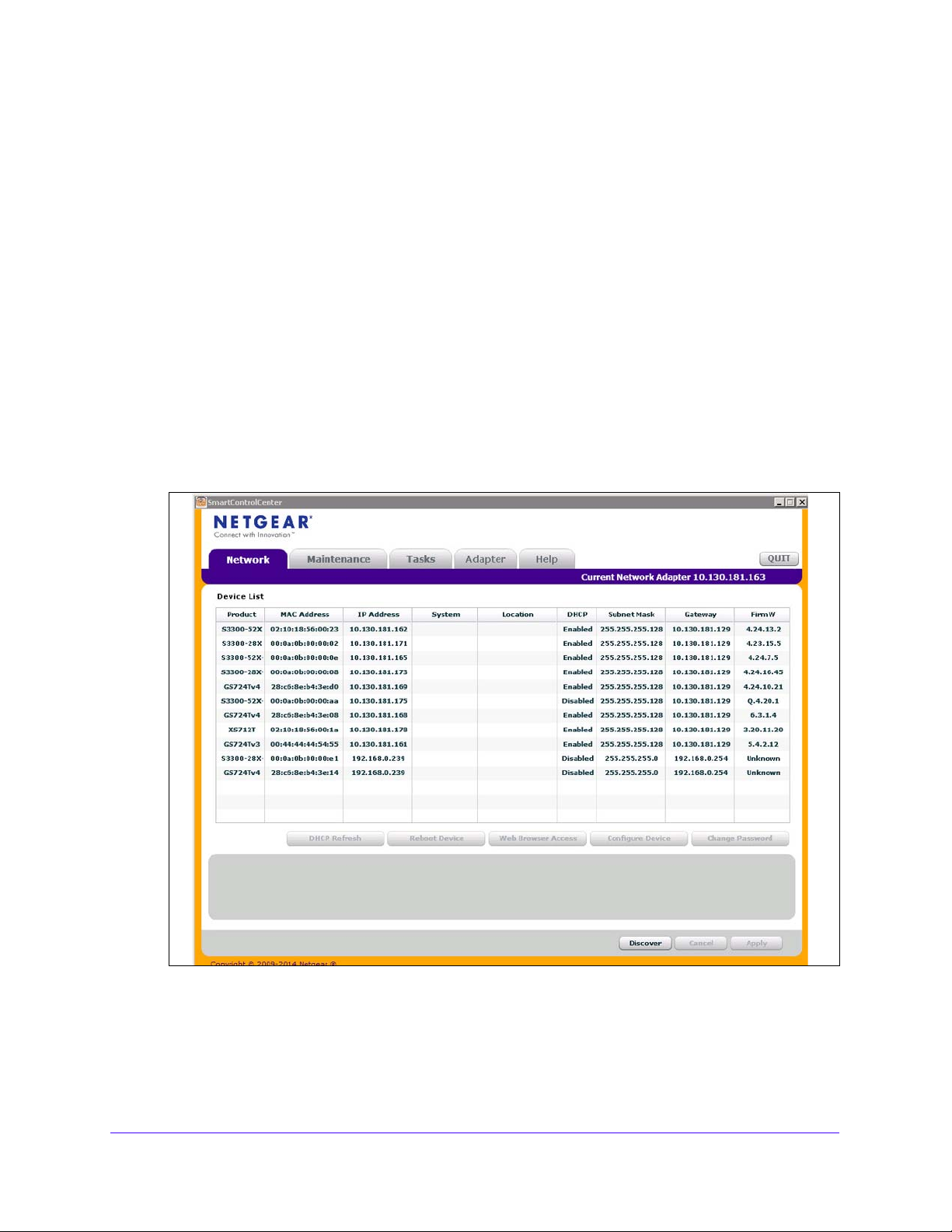
Discover a Switch in a Network with a DHCP Server
This section describes how to set up your switch in a network that has a DHCP server. The
DHCP client on the switch is enabled by default. When you connect it to your network, the
DHCP server will automatically assign an IP address to your switch. Use the Smart Control
Center to discover the IP address automatically assigned to the switch.
To install the switch in a network with a DHCP server:
1. Connect the switch
2. Power
3. In
4. S
5. Click the Disco
A screen similar to the one shown in
on the switch by connecting its power cord.
stall the Smart Control Center on your computer.
tart the Smart Control Center.
to a network with a DHCP server.
ver button for the Smart Control Center to find your switch.
the following figure displays.
Figure 1. Smart Control Center - Discover
6. Make a note of the displayed IP address assigned by the DHCP server.
You will need this value to access the switch directly fro
the Smart Control Center).
Getting Started
14
m a web browser (without using
Page 15
S3300 Smart Managed Pro Switch
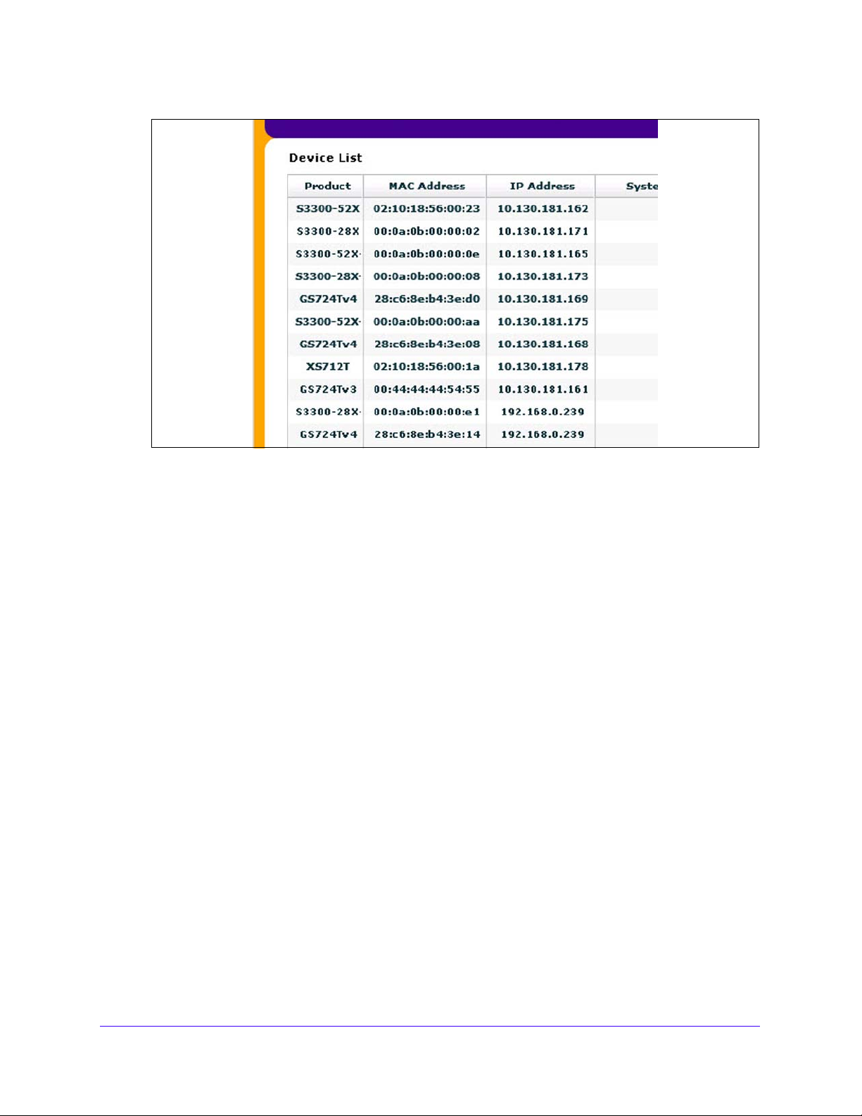
Figure 2. Smart Control Center - Device List
7. Select your switch by clicking the line that displays the switch, then click the
Web Browser Access bu
The Smart Control Center launches a browser that d
tton.
isplays the login screen of the
selected device.
Use your web browser to manage your switch. The default password is p
assword. For
more information about the screen layout and options, see Use the Web Interface on
page 21.
Getting Started
15
Page 16

S3300 Smart Managed Pro Switch
Discover a Switch in a Network without a DHCP Server
This section describes how to use the Smart Control Center to set up your switch in a
network without a DHCP server. If your network has no DHCP service, you must assign a
static IP address to your switch. If you choose, you can assign it a static IP address, even if
your network has DHCP service.
To assign a static IP address:
1. Connect the switch to your existing network.
2. Power on the switch by connecting its power cord.
3. Install the Smart Control Center on your computer.
4. Start the Smart Control Center.
5. Click the Discover button for the Smart Control Center to find your S3300 switch.
The utility broadcasts Layer 2 discovery packets within the broadcast domain to discover
the switch.
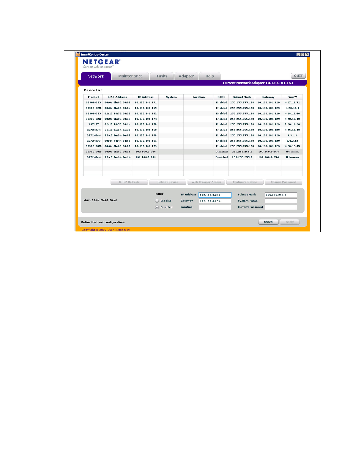
6. Select the switch, then click the Configure Device button.
The screen expands to display additional fields at the bottom.
7. Select the Disabled radio button to disable DHCP.
8. Enter the static switch IP address, gateway IP address, and sub net mask for the switch .
Getting Started
16
Page 17
S3300 Smart Managed Pro Switch
Figure 3. Smart Control Center - Configure Device
9. Type your password to cont inue with the configuration change.
Tip: Y
10. Click the Ap
Ensure that your computer and the switch are in the same subnet. Make a note of these
settings
ou must enter the current password every time you use the Smart
Control Center to update the switch setting. The default password is
password.
ply button to configure the switch with the network settings.
for later use.
Configure the Network Settings on the Administrative System
If you choose not to use the Smart Control Center to configure the network information on the
switch, you can connect directly to the switch from an administrative system, such as a
computer or laptop. The IP address of the administrative syste m must be in the same subnet
as the default IP address on the switch. For most networks, this means you must change the
IP address of the administrative system to be on the same subnet as the default IP address
of the switch (192.168.0.239).
Getting Started
17
Page 18
S3300 Smart Managed Pro Switch
The method to change the IP address on an administrative system varies depending on the
operating system version. You need Windows Administrator privileges to change these
settings. The following procedures show how to change the static IP address on a computer
running a Microsoft Windows 7.
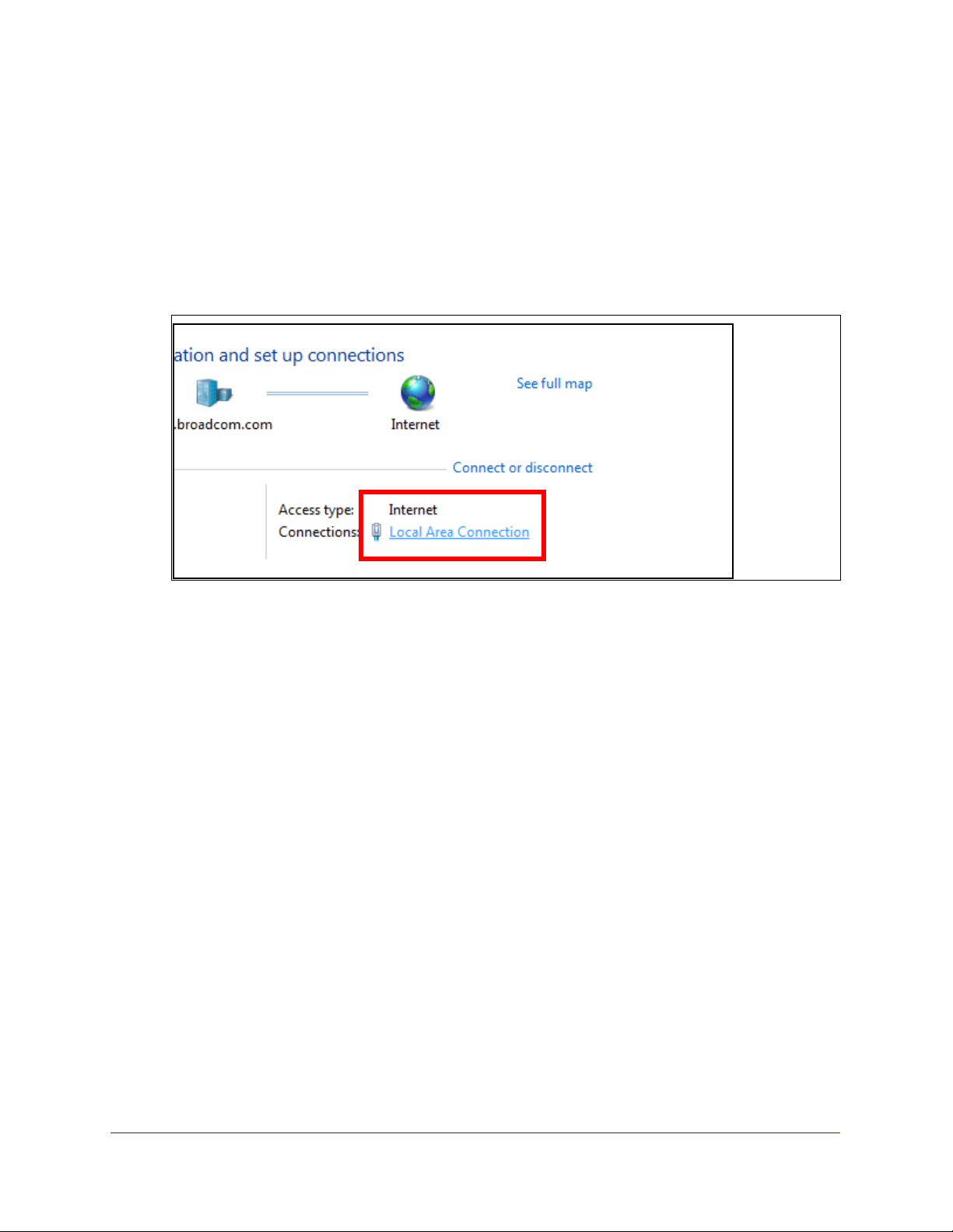
To modify the network settings on your administrative system:
1. Op
2. Click the L
en the Control Panel and click the Network and Sharing Center option.
ocal Area Connection link.
Figure 4. Local Area Connection
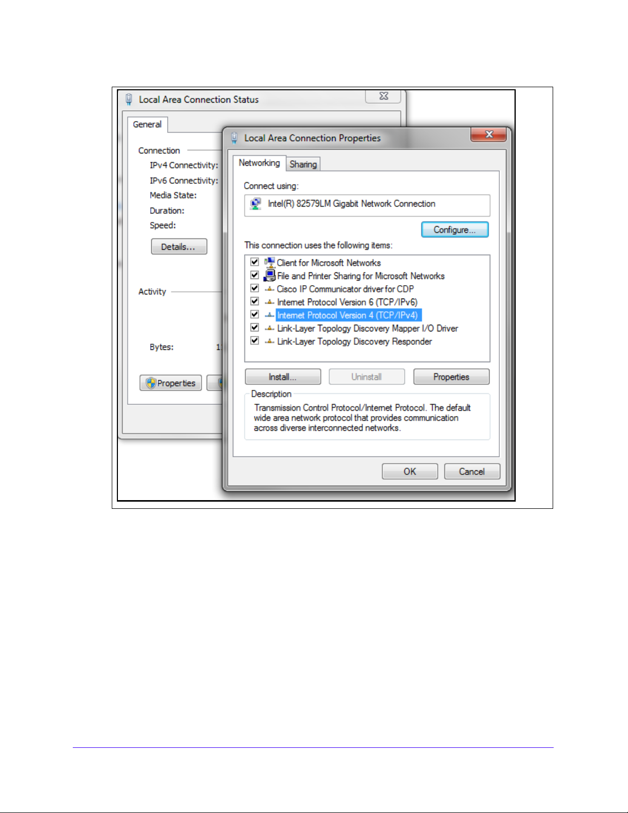
3. In the Local Area Connection Status window, click the Properties button.
The Local Area Connection Properties window displays.
Getting Started
18
Page 19
S3300 Smart Managed Pro Switch
Figure 5. Local Area Connection Properties Window
4. Select the Internet Protocol Version 4 (TCP/IPv4) option, and then click the Properties
button.
The Internet Protocol Version 4 (TCP/IPv4) Properties window appears.
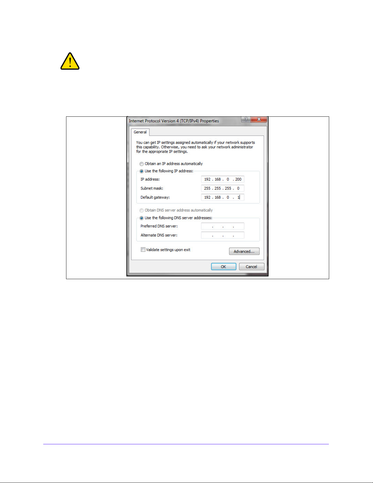
5. Select t
he Use the following IP address option and set the IP address of the administrative
system to an address in the 192.168.0.0 network, such as 192.168.0 .200.
The IP address must be different from that of the switch but within the same subnet.
Getting Started
19
Page 20
S3300 Smart Managed Pro Switch
WARNING:
When you change the IP address of your administrative system,
you lose your connection to the rest of the network. Be sure to write
down your current network address settings before you change
them.
Figure 6. IP Address Settings
6. Click the OK button.
To configure a static address on the switch:
1. Use a straig
ht-through cable to connect the Ethernet port on the administrative system
directly to any port on the switch.
2. Open a we
b browser on your computer and connect to the management interface.
For more information, see Access the Management Interface from a Web Browser on
page 21.
3. Change th
e network settings on the switch to match those of your network.
For more information, see IP Configuration on page 48.
After you change the network settings on the switch, return the network configuration on your
administrative system to the
original settings.
Getting Started
20
Page 21

S3300 Smart Managed Pro Switch
Access the Management Interface from a Web Browser
To access the switch management interface, use one of the following methods:
• From the Smart Control Center, select the switch and click the Web Browser Access
button. For more information, see the Smart Control Center User Guide at
http://docs.netgear.com/scc/enu/202-10685-01/index.htm.
• Open a web browser and enter the IP address of the switch in the address field.
You must be able to ping the IP address of the switch web management interface from your
administrative system for web access to be available. If you used the Smart Control Center to
set up the IP address and subnet mask, either with or without a DHCP server, use that IP
address in the address field of your web browser. If you did not change the IP address of the
switch from the default value, enter 192.168.0.239 in the address field.
Clicking the Web Browser Access button on the Smart Control Center or accessing the
switch directly from your web browser displays the Login screen.
Understand the User Interfaces
The switch software includes a set of comprehensive management functions for configuring
and monitoring the system by using one of the following methods:
• Web user interface
• Simple Network Management Protocol (SNMP)
Each of the standards-based management methods allows you to configure and monitor the
components of the switch software. The method you use to manage the system depends on
your network size and requirements, and on your preference.
This manual describes how to use the web interface to manage and monitor the system.
Use the Web Interface
To access the switch by using a web browser, the browser must meet the following software
requirements:
• HTML version 4.0, or later
• HTTP version 1.1, or later
• Java Runtime Environment 1.6 or later
Supported web browsers:
The following browsers were tested and support the web browser–based management
interface. Later browser versions might function fine but were not teste d. The su pported web
browsers include the following:
• Microsoft Internet Explorer (IE) versions 10-11
Getting Started
21
Page 22
S3300 Smart Managed Pro Switch
Navigation tab Configuration menus
Logout button
Help link
Buttons
Screen menu
Configuration status and options
Help screen
• Microsoft Edge
• Mozilla Firefox version
s 40, 46.0.1
• Chrome version 45
• Safari on Windows OS 5.1,
• Safari on Mac OS 8.0
To log on to the web interface:
6.0
1. Op
en a web browser and enter the IP address of the switch in the web browser address
field.
The login screen displays.
ype the password in the Password field.
2. T
The factory default password is p
3. Click the L
ogin button.
assword. Passwords are case-sensitive.
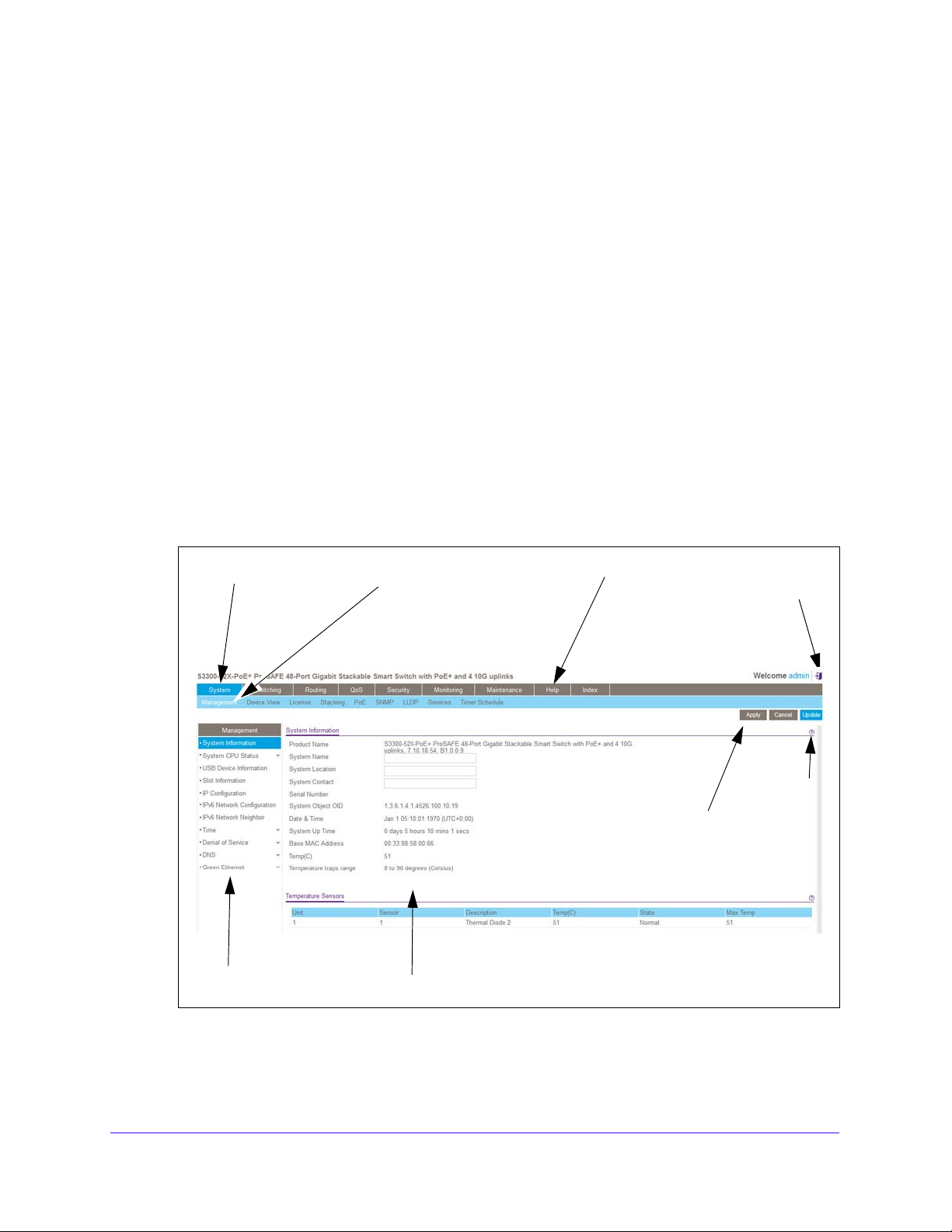
After the system authenticates you, the System Information screen displays.
The following figure shows the layout of the web interface.
Figure 7. Smart Switch Web Interface
Getting Started
22
Page 23
S3300 Smart Managed Pro Switch
Link
Submenu
links
Navigation Tabs, Configuration Menus, and Screen Menu
The navigation tabs along the top of the web interface give you quick access to the various
switch functions. The tabs are always available and remain constant, regardless of which
feature you configure.
When you select a tab, the features for that tab appear as menus directly under the tabs. The
configuration menus in t
he blue bar change according to the navigation tab that is selected.
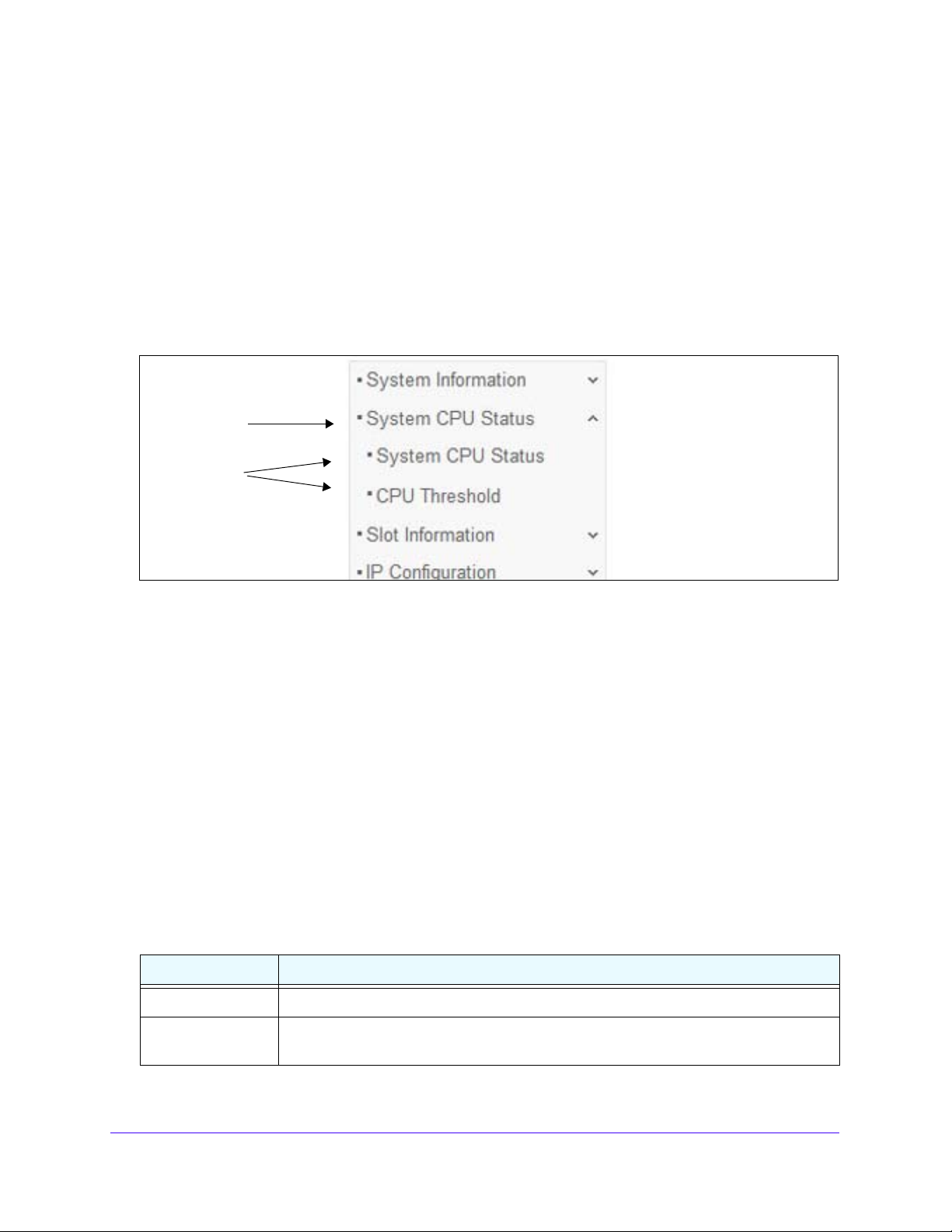
The configuration screens for each feature are availa
ble as submenu links in the screen
menu on the left side of the screen. Some items in the menu expand to reveal multiple
submenu links, as the following figure shows.
Figure 8. Submenu Links
When you click a menu item that includes multiple configuration screens, the item becomes
preceded by a down arrow symbol and expands to display the additional submenu links.
Configuration and Status Options
The area directly under the configuration menus and to the right of the links displays the
configuration information or status for the screen you select. On screens that contain
configuration options, you can input information into fields or select options from drop-down
lists.
Each screen contains access to the HTML-b
ased help that explains the fields and
configuration options for the screen. Each screen also contains command buttons.
The following table shows the command buttons that are used throughout the screens in the
interface:
web
Table 1. Command buttons
Button Function
Add Places the new item configured in the heading row of a table.
Apply Sends the updated configuration to the switch. Configuration changes take effect
immediately.
Getting Started
23
Page 24
S3300 Smart Managed Pro Switch
Table 1. Command buttons (continued)
Button Function
Cancel Abandons the configuration changes on the screen and resets the data to the previous
values.
Delete Removes the selected item.
Refresh/Update Refreshes/updates the screen with the late
Logout Ends the session.
Clear Clears all information and returns the switch to its default settings.
st information from the device.
Device View
The Device View is a Java® applet that displays the ports on the switch. This graphic
provides an alternate way to navigate to configuration and monitoring options. The graphic
also provides information about device ports, current configuration and status, table
information, and feature components.
The Device View is available by selecting Syste
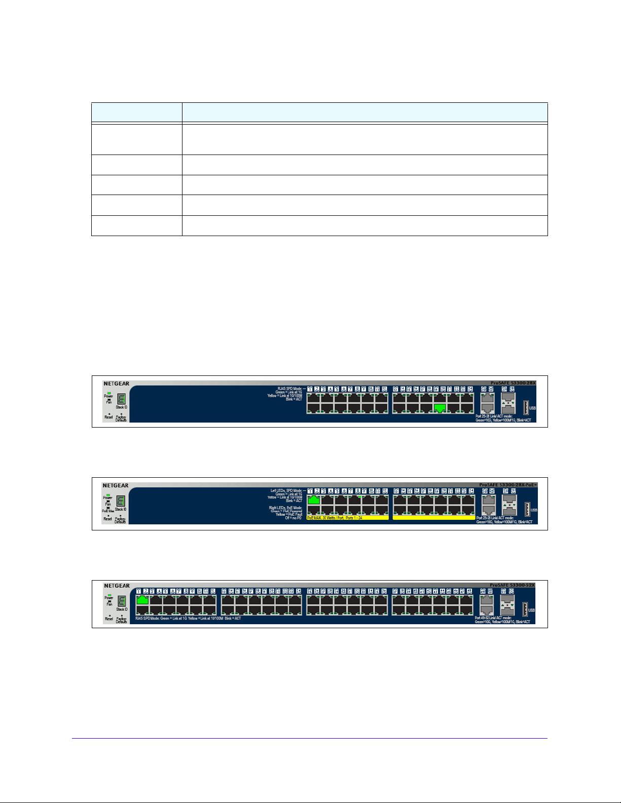
The following image shows the Device View of the S3300-28X.
Figure 9. S3300-28X
The following image shows the Device View of the S3300-28X-PoE+.
m Device View.
Figure 10. S3300-28X-PoE+
The following image shows the Device View of the S3300-52X.
Figure 11. S3300-52X
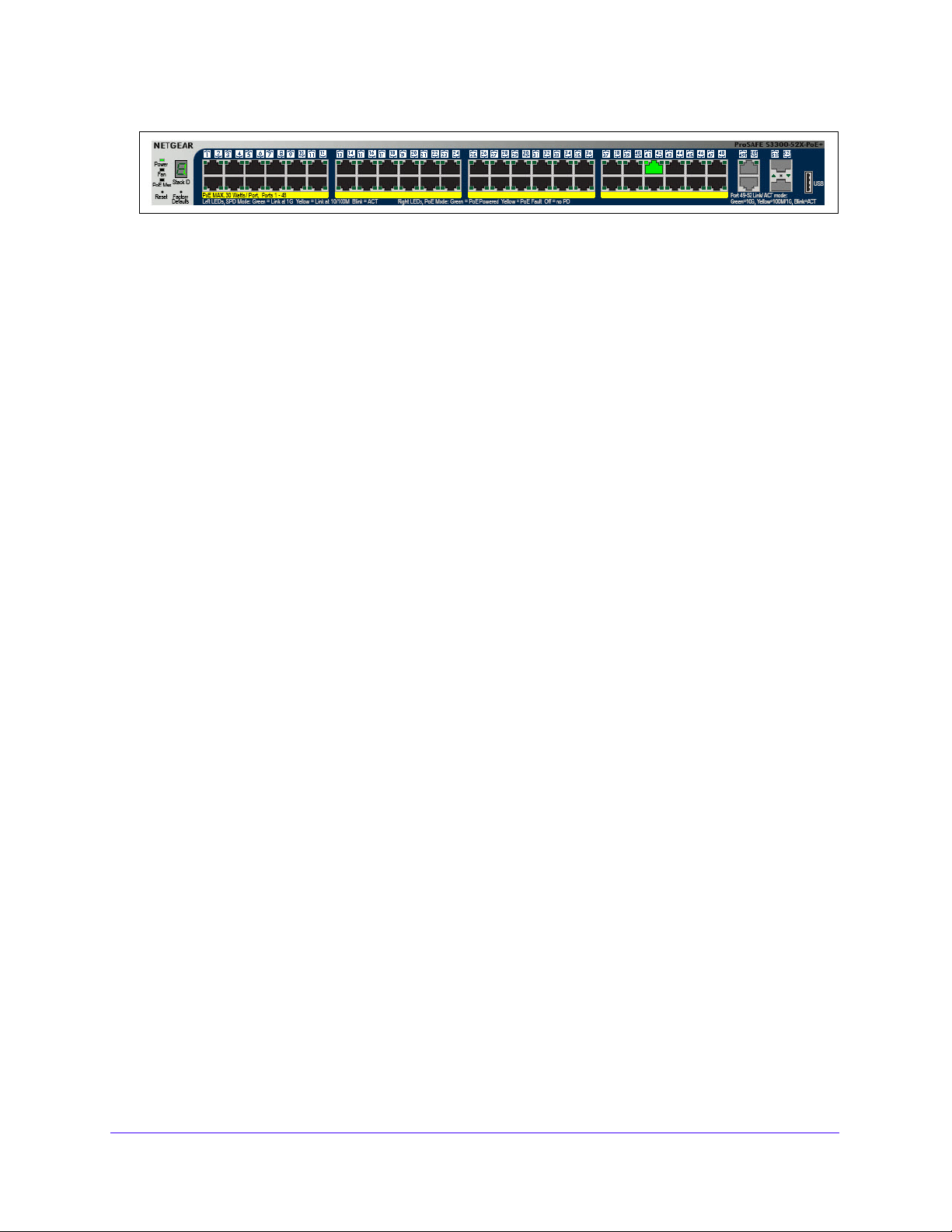
The following image shows the Device View of the S3300-52X-PoE+.
Getting Started
24
Page 25
S3300 Smart Managed Pro Switch
Figure 12. S3300-52X-PoE+
In the S3300, the four uplink ports can work in either Stacking mode or in Ethernet mode.
• By defa
• W
ult those ports are in Stacking mode, and their color is gray.
hen these ports are configured in Ethernet mode, then their color is blank (not
connected).
Depending upon the status of the port, the port color in Device View is either red, green,
yellow
• Green
• Red
, gray or black.
and yellow indicate that the port is enabled.
indicates that an error has occurred on the port or that the port is administratively
disabled.
• Black ind
When a link is present, the color of the port in th
• A g
- 1
- 1
- Fiber SFP+ port
• A yellow spe
- 1
- Fiber SFP+ port
icates that no link is present.
e device view is either green or yellow:
reen speed LED indicates operational ports at the following link speed:
0G copper ports — 10 Gbps
G copper ports — 1000 Mbps (1 Gbps)
s — 10 Gbps
ed LED indicates operational ports at the following link speed:
G copper ports — 10/100 Mbps
s — 1000 Mbps
Click the port you want to view or configu
configuration options, as shown in Figure 13 on p
re to see a menu that displays statistics and
age 26. Select the menu option to access
the page that contains the configuration or monitorin
Getting Started
25
g options.
Page 26
S3300 Smart Managed Pro Switch
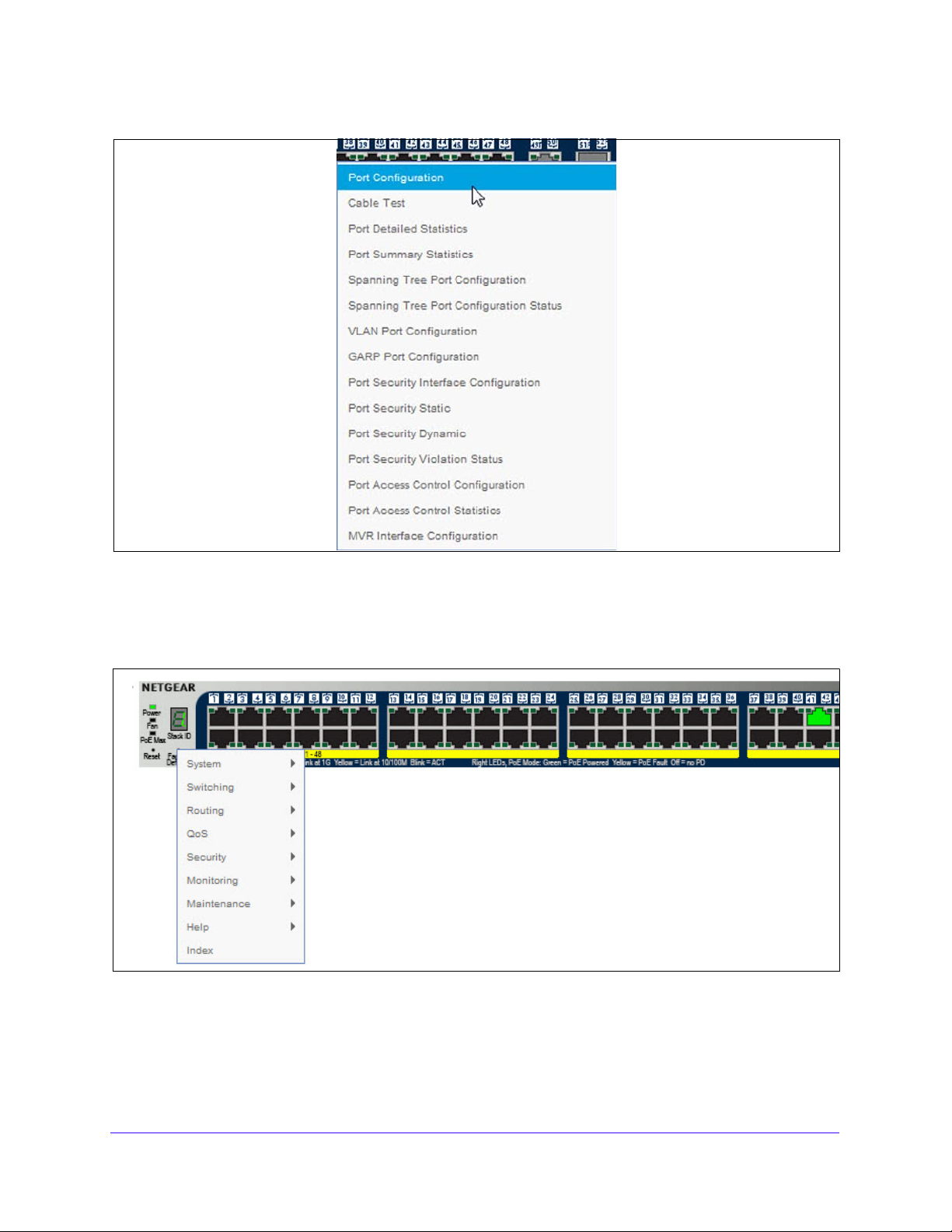
Figure 13. Device View S3300-52X Port Menu
If you click the graphic but do not click a specific port, the main menu appears, as Figure 14,
Device View Main Menu shows. This menu contains the same option as the navigation menu
at the top of the screen.
Figure 14. Device View Main Menu
The System LEDs are located on the left side of the front panel.
Getting Started
26
Page 27

S3300 Smart Managed Pro Switch
Power/Status LED
The Power LED is a bicolor LED that serves as an indicator of power and diagnostic status.
T
he following indications are given by the following LED states:
• A solid gree
n LED indicates that the power is supplied to the switch and operating
normally.
• A solid ye
• No
lit LED indicates that power is disconnected.
llow LED indicates that system is in the boot-up stage.
FAN Status LED
FAN status is indicated as follows:
• A solid ye
• No
lit LED indicates that the fan is operating normally.
llow LED indicates that the fan is faulty.
Stack ID LED
The seven Segment LED displays the unit number in green. The dot LED on the bottom right
lows when either the unit is a Stack Manager or Standalone (meaning that it is not
g
connected in a Stack).
PoE Max LED
The PoE Max LED is for the S3300-28X-PoE+ and S3300-52X-PoE+ devices.
f indicates the system has more than 7 watts (W) of PoE power available for another
• Of
PD device.
• A stead
• A b
y yellow LED indicates that less than 7W of PoE power is available.
linking yellow LED indicates the device was active in the past two minutes.
Help Access
Every screen contains a button to launch online help , which contains information to
assist in configuring and managing the switch. The
online help screens are context-sensitive.
For example, if the IP Addressing screen is open, the help topic for that screen displays if you
click Help. Figure 7, Smart Switch Web Interface on p
age 22 shows the location of the Help
link on the web interface.
User-Defined Fields
User-defined fields can contain 1 to 159 characters, unless otherwise noted in the field label
on the configuration screen. All alphanumeric and special characters can be used except for
the following (unless specifically noted for that feature):
Getting Started
27
Page 28

S3300 Smart Managed Pro Switch
Table 2. Disallowed characters in user-defined fields
Character Definition
\ Backslash
/ Forward slash
* Asterisk
? Question mark
< Less than
> Greater than
| Pipe
Getting Started
28
Page 29
S3300 Smart Managed Pro Switch
Use SNMPv3
The switch software supports the configuration of SNMP groups and users that can manage
traps that the SNMP agent generates.
The switch uses both standard public MIBs for standard functionality and private MIBs that
support additional switch functionality
main object for interface configuration is in -SWITCHING-MIB, which is a private MIB. Some
interface configurations also involve objects in the public MIB, IF-MIB.
SNMP is enabled by default. The System Information screen, which is the screen that
isplays after a successful login, displays the information you need to configure an SNMP
d
manager to access the switch. To configure information for SNMPv1 or SNMPv2, see SNMP
on page 95.
. All private MIBs begin with a hyphen (-) prefix. The
Any user can connect to the switch using the SNMPv3 proto
col, but for authentication and
encryption, the switch supports only one user which is admin; therefore there is only one
profile that can be created or modified.
To configure authentication and encryption settings for the SNMPv3 admin profile by
using the web interface:
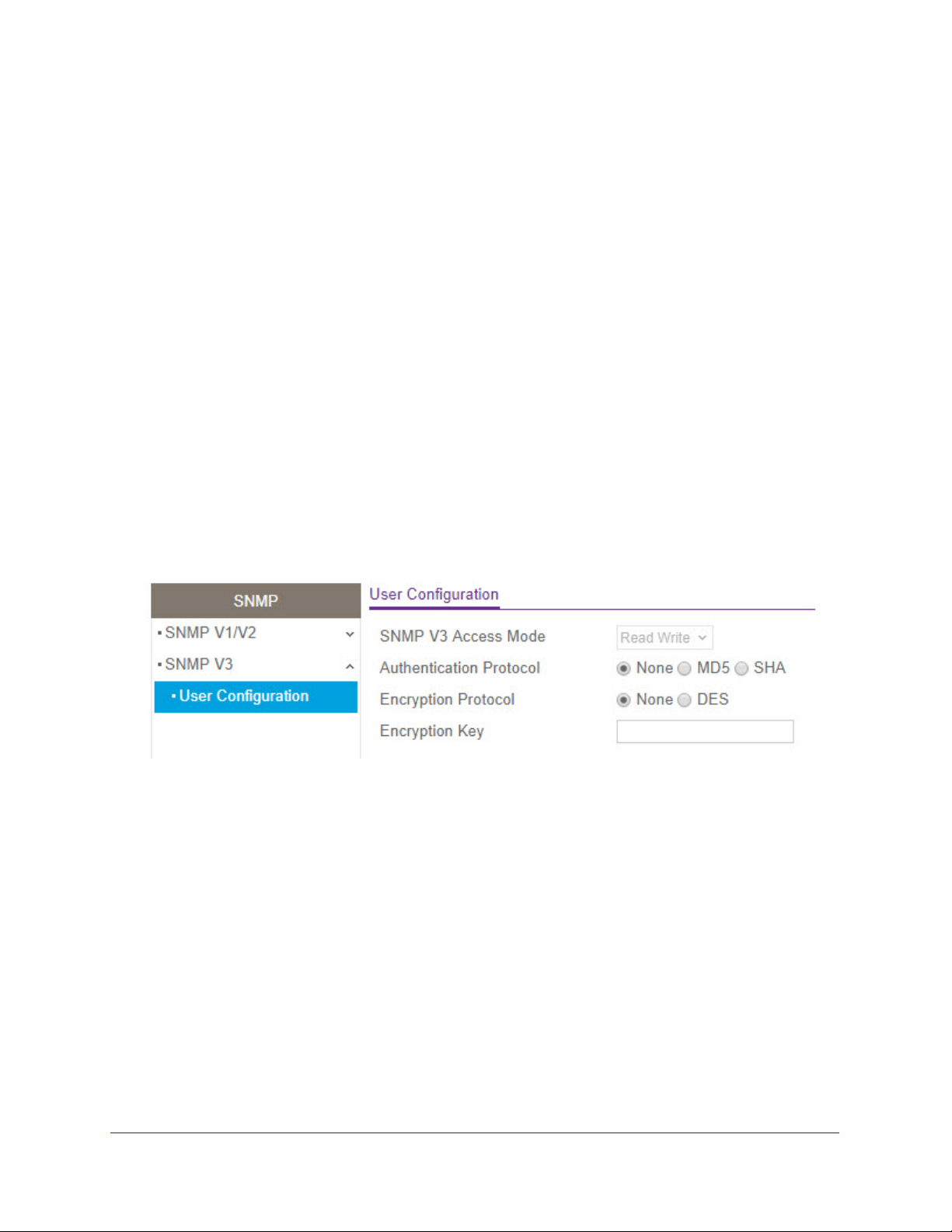
1. Select Sy
stem > SNMP > SNMPv3 > User Configuration. The User Configuration
screen displays.
Figure 15. SNMPv3 User Configuration
The SNMPv3 Access Mode is a read-only field that shows the access privileges for the
user account. The admin account always has Read/Write access, and all other accounts
have Read Only access.
o enable authentication, select an Authentication Protocol option.
2. T
If the authentication protocol is MD5 or SHA,
the user login password will be used as
SNMPv3 authentication password. To configure the login password, see Change
Password on p
3. T
o enable encryption:
a. I
n the Encryption Protocol field, select the DES option to encrypt SNMPv3 packets
age 241.
using the DES encryption protocol.
b. I
n the Encryption Key field, enter an encryption code of eight or more alphanumeric
characters.
4. Click the Ap
ply button.
Getting Started
29
Page 30

S3300 Smart Managed Pro Switch
Interface Naming Convention
The switch supports physical and logical interfaces. Interfaces are identified by their type and
the interface number. All the physical ports are as follows:
• S3300-28X. The ProSafe S3300-28X Smart switch is a stackable small/medium business
class switch.This 28-port Gigabit Ethernet Layer 2 switch provides ports as follows:
- Ports 1–24 are 1GBaseT ports (RJ45)
- Ports 25–26 are two dedicated 10GBaseT ports supporting 10G/1G/100M speeds
- Ports 27-28 are two dedicated SFP+ ports supporting 10G and 1000M speeds
The dedicated 10GBaseT and SFP+ ports can be configured as Ethernet ports or as
stacking links. Up to six S3300 switches can be stacked together to form a larger device
which can be managed at a single IP address. This switch supports management via
IPv4 and IPv6, supports 32 Static Routes, and provides Green Ethernet (EEE) capability.
• S3300-28X-PoE+. The S3300-28X-PoE+ switch is identical to the S3300-28X except it
supports PoE+ on the 24 1G ports.
• S3300-52X. The ProSafe S3300-52X Smart switch is a stackable small/medium business
class switch. This 52-port Gigabit Ethernet Layer 2 switch provides the following:
- Ports 1–48 are 1GBaseT ports (RJ45)
- Ports 49–50 are two dedicated 10GBaseT ports supporting 10G/1G/100M speeds
- Ports 51-52 are two dedicated SFP+ ports supporting both 10G and 1000M speeds
The dedicated 10GBaseT and SFP+ ports can be configured as Ethernet ports or as
stacking links. Up to six S3300 switches can be stacked together to form a larger device
which can be managed at a single IP address. This switch supports management via
IPv4 and IPv6, supports 32 Static Routes, and provides Green Ethernet (EEE) capability.
• S3300-52X-PoE+. The ProSafe S3300-52X-PoE+ Smart switch is identical to the
S3300-52X except it supports PoE+ on the 48 1G ports.
The number of the port is identified on the front panel. You can configure the logical
interfaces by using the software. The following table describes the naming convention for all
interfaces available on the switch.
Table 3. Interface naming conventions
Interface Description Example
Physical The physical ports include Gigabit ports and are numbered
sequentially starting from one using the following format:
X/gY or X/xgY. X for the unit ID, g is for a 1G port, xg is for a
10G port, and Y is the port number.
1/g1, 1/g2,
2/xg27
Getting Started
30
Page 31

S3300 Smart Managed Pro Switch
Table 3. Interface naming conventions
Interface Description Example
Link aggregation group (LAG) LAG interfaces are logical interfaces that are only used for
bridging functions.
CPU management interface This is the internal switch interface responsible for the switch
base MAC address. This interface is not configurable and is
always listed in the MAC Address Table.
l1, l2, l3
c1
Getting Started
31
Page 32

S3300 Smart Managed Pro Switch
Configuring Interface Settings
For some features that allow you to configure interface settings, you can apply the same
settings simultaneously to any of the following:
• A single
• M
ultiple ports
• All p
• A single
• M
ultiple LAGs
• All L
• Multiple port
• All p
port
orts
LAG
AGs
s and LAGs
orts and LAGs
Many of the screens that allow you to configure or view interface settings include links to
displa
y all ports, all LAGs, or all ports and LAGs on the screen.
Figure 16. Links to Display Interfaces
Use these links as follows:
• T
o display all ports, click the 1 link.
• T
o display all LAGs, click the LAGS link.
• T
o display all ports and LAGs, click the All link.
The procedures in this section describe how to select the ports and LAGs to configure.
To configure a single port by using the Go To Interface field:
1. Ensu
2. In
3. Click the Go but
re that the screen is displaying all ports, and not only the LAGs.
the Go To Interface field, type the port number, for example g4.
ton.
The check box associated with the interface is selected,
the row for the selected interface
is highlighted, and the interface number appears in the heading row.
Figure 17. Go To Interface Example
Getting Started
32
Page 33

S3300 Smart Managed Pro Switch
4. Configure the desired settings.
5. Click the Apply button.
The settings you configure in the heading row are applied to the selected interface.
To configure a single LAG by using the Go To Interface field:
1. Click the LAGS link or the All link to display the LAGs.
2. In the Go To Interface field, type the LAG number, for example l3.
3. Click the Go button.
The check box associated with the interface is selected, the row for the selected interface
is highlighted, and the interface number appears in the heading row.
4. Configure the desired settings.
5. Click the Apply button.
The settings you configure in the heading row are applied to the selected interface.
To configure a single port:
1. Ensure that the screen is displaying all ports, and not only the LAGs.
2. Select the check box next to the port number.
The row for the selected interface is highlighted, and the interface number appears in the
heading row.
3. Configure the desired settings.
4. Click the Apply button.
The settings you configure in the heading row are applied to the selected interface.
To configure a single LAG:
1. Click the LAGS link or the All link to display the LAGs.
2. Select the check box next to the LAG number.
The row for the selected interface is highlighted, and the interface number appears in the
heading row.
3. Configure the desired settings.
4. Click the Apply button.
The settings you configure in the heading row are applied to the selected interface.
To configure multiple ports:
1. Ensure that the screen is displaying all ports, and not only the LAGs.
2. Select the check box next to each port to configure.
The row for each selected interface is highlighted.
Getting Started
33
Page 34

S3300 Smart Managed Pro Switch
Figure 18. Select Multiple Ports
3. Configure the desired settings.
4. Click the Appl
y button.
The settings you configure in the heading row are
T o configure multiple LAGs:
1. Click the
2. Select the check box
LAGS link or the All link to display the LAGs.
next to each LAG to configure.
The check box associated with each interface is selected, and the row for each selected
inte
rface is highlighted.
3. Configu
4. Click the Appl
re the desired settings.
y button.
The settings you configure in the heading row are
To configure all ports:
1. Ensu
2. Select the check box
re that the screen is displaying only ports, and not LAGs.
in the heading row.
The check box associated with every port is selected, and the rows for all ports are
hig
hlighted.
applied to all selected interfaces.
applied to all selected interfaces.
Getting Started
34
Page 35

S3300 Smart Managed Pro Switch
Figure 19. Select All Ports
3. Configure the desired settings.
4. Click the Ap
ply button.
The settings you configure in the heading row are applied to all ports.
To configure all LAGs:
1. Click the LAGS link to display only the L
2. Select th
e check box in the heading row.
The check box associated with every LAG is se
highlighted.
3. Conf
4. Click the Ap
igure the desired settings.
ply button.
The settings you configure in the heading row are applied to all LAGs.
To configure multiple ports and LAGs:
1. Click the All link to
2. Select th
e check box associated with each port and LAG to configure.
display all ports and LAGs.
The rows for the selected ports and LAGs are highlighted.
3. Conf
4. Click the Ap
igure the desired settings.
ply button.
The settings you configure in the heading row are applied to the selected po rts and LAGs.
To configure all ports and LAGs:
AG interfaces.
lected, and the rows for all LAGs are
1. Click the All link to
2. Select th
e check box in the heading row.
display all ports and LAGs.
The check box associated with every port and LAG is selected, and the rows for all ports
nd LAGs are highlighted.
a
3. Conf
igure the desired settings.
Getting Started
35
Page 36

S3300 Smart Managed Pro Switch
4. Click the Apply button.
The settings you configure in the heading row are applied to all ports and LAGs.
Online Help
The Help main navigation tab of the web management interface provides access to the
menus that are described in the following sections:
• Support on page 36
• User Guide on page 36
Support
The Support screen provides access to the NETGEAR support website at
support.netgear.com.
To access the support website from the web management interface:
1. Select Help > Support.
The Support screen displays.
2. Click the Apply button to access the NETGEAR support site for the switch.
User Guide
The S3300 Smart Managed Pro Switch User Guide (the guide you are now reading) is
available at the NETGEAR download center at
To access the reference manual online from the web management interface:
1. Select Help > User Guide.
2. Click the Apply button to access the NETGEAR do wnload center.
3. Enter the model number of the switch.
4. Locate the S3300 Smart Managed Pro Switch User Guide on the product support web
screen.
downloadcenter.netgear.com.
Getting Started
36
Page 37

S3300 Smart Managed Pro Switch
Registration
To qualify for product updates and product warranty, NETGEAR encourages you to register
your product. The first time that you connect to the switch while it is connected to the Internet,
you have the option to register your product. At any time, you can register your product from
the web management interface, or you can visit the NETGEAR website for registration at
https://my.netgear.com/registration/login.aspx.
To register the switch with NETGEAR:
1. Select Help > Register.
The Registration screen displays.
2. Click the Register button.
A pop-up window opens and displays the NETGEAR product registration web screen.
3. Follow the on-screen instructions to complete the product registration process.
Getting Started
37
Page 38

2. Configure System Information
2
Use the features you access from the System navigation tab to define the switch’s relationship to
its environment. The System navigation tab provides access to the configuration menus
described in the following sections:
• Management on page 39
• Device View on page 76
• License on page 76
• Switch Stack Configuration on pag e 77
• PoE on page 90
• SNMP on page 95
• LLDP on page 98
• Services on page 113
• Timer Schedule on page 132
38
Page 39

S3300 Smart Managed Pro Switch
Management
This section describes how to display the switch status and specify some basic switch
information, such as the management interface IP address, system clock settings, and DNS
information. From the Management configuration menu, you can access screens described
in the following sections:
• System Information on
• System CPU Status on p
• USB Device Information on p
• Slot Information on
• IP Configuration on p
• IPv6 Network Configuration on p
• IPv6 Network Neighbor on p
• Time on
• Denial of Service on p
• DNS on p
• Green Ethernet on p
page 53
age 64
page 39
age 43
age 45
page 47
age 48
age 50
age 52
age 61
age 67
System Information
After a successful login, the System Information screen displays. Use this screen to configure
and view general device information.
To define a system name, location, and contact:
1. Sel
ect System > Management > System Information.
The System
Figure 20. Management - System Information
Information screen displays.
Configure System Information
39
Page 40

2. Define the following fields:
• System Name.
Enter the name you want to use to identify this switch. Y ou can use up
to 255 alphanumeric characters. The factory default is blank.
S3300 Smart Managed Pro Switch
• System Location. Enter the
location of this switch. You can use up to 255
alphanumeric characters. The factory default is blank.
• System Con
tact. Enter the contact person for this switch. You can use up to 255
alphanumeric characters. The factory default is blank.
3. Click the Appl
y button.
The system parameters are applied, and the device is updated.
The following table describes the status information
Table 4. System Information Screen Status Fields
Field Description
Product Name The product name that describes the switch.
Serial Number The serial number of the switch.
System Object OID The base object ID for the switch's enterprise MIB.
Date & Time The current date and time.
System Up Time The number of days, hours, and
restart.
Base MAC Address The universally assigned network address.
the System Information screen displays.
minutes since the last system
Temp (C) The general temperature of the switch in degrees Celsius.
Temperature Traps Range Identifies the minimum and maximum deg
traps range.
rees of the temperature
Note: NSDP supports TLV for Serial Number.
TLV Value Description
Serial Number 1…21 For Smart Switch:
1 Byte:
0-Invalid
1-Valid
Next 20 bytes: Serial number string
Temperature Sensors
This screen shows the temperature of different system sensors. The temperature is instant
and can be refreshed when you press the Update button.
Configure System Information
40
Page 41

S3300 Smart Managed Pro Switch
Figure 21. System Information - Temperature Sensors Status
The following table describes the status information displayed in the Temperature Sensors
section of the System Information screen.
Table 5. System Information - Temperature Sensors Status Fields
Field Description
Unit The unit number in the stack.
Sensor The temperature sensor for the given unit.
Description The description of the temperature sensor.
Temp (C) The current temperature of
degrees Celsius.
State The unit temperature state.
Max Temp The maximum temperature of the CPU and MACs. The maximum
temperature
depends on the actual hardware.
the specified sensor of the switch in
Fans
The screen shows the status of the fans. These fans remove the heat generated by the
power, CPU and other chipsets.
Figure 22. System Information - Fan Status
The following table describes the status information displayed in the Fans section of the
System Information screen.
Table 6. System Information - Fans Status Fields
Field Description
Unit The unit number in the stack.
Fan The fan index used to identify the fan for the given stack member.
Description The description of the temperature sensor.
Type Specifies whether the fan module is fixed or removable.
Speed The fan speed.
Configure System Information
41
Page 42

S3300 Smart Managed Pro Switch
Table 6. System Information - Fans Status Fields (continued)
Field Description
Duty Level The duty level of the fan.
State Sp ecifies whether the fan is running or stopped.
Power Supplies
This screen shows the power supplies status.
Figure 23. System Information - Power Supplies Status
The following table describes the status information displayed in the Power Supplies section
of the System Information screen.
Table 7. System Information - Power Supplies Status Fields
Field Description
Unit The unit number in the stack.
Power Supply The power supply index used for the given stack member.
Description The description of the power supp l y.
Type Indicates whether the power supply is fixed or removable.
State Specifies whether the power modules
is operational or stopped.
Versions
This screen displays the software version of each device.
Figure 24. System Information - Versio ns Information
Configure System Information
42
Page 43

S3300 Smart Managed Pro Switch
The following table describes the information displayed in the Versions section of the System
Information screen.
Table 8. System Information - Versions Information Fields
Field Description
Unit No. The unit number of the switch.
Model Name The model name of the switch.
Boot Version The version of the boot code on the switch.
Software Version The software version currently runni
ng on the switch.
System CPU Status
Use the System CPU Status screen to monitor the CPU, memory resources, and utilization
patterns across various intervals to assess the performance, load, and stability p arameters of
member units.
To display the System CPU Status information:
Select System > Management > System CPU Status > System CPU Status
The Syste
information.
To display a member unit’s CPU status information:
1. Sel
2. In the CPU
Utilization information for all units.
3. The unit’
The CPU Uti
percentage of CPU utilization per task.
m CPU Status screen displays CPU Memory Status and CPU Utilization
ect System > Management > System CPU Status > System CPU Status
Utilization > Unit No. field, select a unit number. Select All to run CPU
s Memory Utilization Report is displayed.
lization screen displays the memory information, task-related information and
Configure System Information
43
Page 44

S3300 Smart Managed Pro Switch
Figure 25. System CPU Status - Unit CPU Utilization
Table 9 describes the information that the System CPU Status screen displays.
Tab le 9. System CPU Status > CPU Memory Status
Field Description
CPU Memory Status
Total System Memory The total memory of the switch in KBytes.
Available Memory The available memory space for th
CPU Utilization
Unit No Select the Unit to display the CPU Utilization information. Select All to display
the CPU Utiliza
tion information for all units.
e switch in KBytes.
Click Update to update the page with the latest information on the switch.
To configure the CPU Threshold information:
Select System > Management > System CPU Status > CPU Threshold.
Configure System Information
44
Page 45

S3300 Smart Managed Pro Switch
Figure 26. CPU Threshold
The CPU Threshold screen allows you to configure thresholds that, when crossed, trigger a
notification. The notification is done via SNMP trap and SYSLOG messages.
1. Def
ine the CPU Threshold fields listed in Table 10.
Table 10. System CPU Stat u s > CPU Threshold
Field Descrip tio n
Rising Threshold Notification is generated when the total CPU utilization exceeds this threshold
lue over the configured time period. The range is 1 to 100.
va
Rising Interval The utilization monitoring time period can be configured from 5 seconds to
86400 seconds in multiples of 5 seconds.
Falling Threshold Notification is triggered when the total CPU utilization falls below this level for a
nfigured period of time. The Falling utilization threshold must be equal or less
co
than Rising threshold value. The Falling utilization threshold notification is made
only if previously a Rising threshold notification was done. Configuring the
Falling utilization threshold and time period is optional. If the Falling CPU
utilization parameters are not configured, then it takes the same value as Rising
CPU utilization parameters. Range is 1 to 100.
Falling Interval The utilization monitoring time period ca
86400 seconds in multiple of 5 seconds.
Free Memory Threshold This is non-configurable data and is the CPU Free Memory Threshold value.
n be configured from 5 seconds to
2. Click the Apply button.
The system parameters are applied, and the device is updated.
3. Click the Canc
el button to cancel the configuration on the screen, and reset the data on the
screen to the latest value of the switch.
USB Device Information
Use the USB Device Information screen to display the USB device status, memory
statistics, and directory details.
Configure System Information
45
Page 46

S3300 Smart Managed Pro Switch
To display the USB Device Information page:
1. Select System > Management > USB Device Information.
2. Th
e USB Device Information scree n displays as shown in Figure 27, USB Device
Information.
3. Click Up
date to update the information on the page to the latest data on the switch.
Note: The system only detects and manages the USB device installed in th e
master unit.
The limitations for the USB Device supported on the S3300 are as follows:
• The USB disk
• The USB disk
• The write/read
should comply for USB 2.0.
should have a filetype of FAT32 or VFAT. NTFS is not supported.
speed is about 1 Mbps due to a hardware limitation.
Figure 27. USB Device Information
Table 11 describes the nonconfigurable information that the USB Device Information screen
displays.
Table 11. USB Device Information
Field Description
USB Device Details
Device Status Specifies the current status of device.
tive if the device is USB plugged in and recognize d by the switch.
• Ac
active if the device is not mounted.
• In
• Invalid if the device is not present or an invalid device is plugged in.
USB Memory Statistics
Total Size Displays the USB flash device stor
Configure System Information
46
age size in bytes.
Page 47

S3300 Smart Managed Pro Switch
Table 11. USB Device Information (continued)
Field Descrip tio n
Bytes Used Displays the size of memory used on the USB flash device.
Bytes Free Displays the size of memory free on the USB flash device.
USB Directory Details
File Name Displays the name of the file stored in the USB flash drive.
File Size Displays the size, in bytes, of the file stored in the USB flash drive.
Modification Time Displays the last modification time of the file stored in the USB flash drive.
Slot Information
Use the Slot Information screen to display details about the different slots in the dif ferent units
in the switch stack.
To display the Slot Information:
Select System > Management > Slot Information.
Table 12 describes the information that the Slot Information screen displays.
Table 12. Slot Information
Field Descrip tio n
Slot Summary
Slot Identifies the slot using the format unit/slot.
Status Displays whether th e slot is empty or full.
Administrative State Displays whether the slot is administratively enabled or disabled.
Power State Displays whether the slot is powered on or not.
Configured Card Model IDDisplays the model ID of the card configured for the slot.
Configured Card
Description
Inserted Card Model ID Displays the model ID of the card inserted into the slot.
Inserted Card Description Displays the description of the card inserte d into the slot.
Displays the description of the card configured for the slot.
Card Power Down Displays whether the card in the slot is powered down.
Card Pluggable Displays whether the inserted card is pluggable or not.
Supported Card
Card Model Displays the list of models of all cards that can be supported.
Configure System Information
47
Page 48

S3300 Smart Managed Pro Switch
Table 12. Slot Information (continued)
Field Description
Card Index Displays the index assigned to the selected card type.
Card Type Displays the hardware type of this supported card. This is a 32-bit data field.
Card Descriptor Displays a data field used to identify the supported card.
Supported Switch
Switch Model ID Displays the list of models of all
Switch Index Displays the index assigned to the selected switch.
Management Preference Displays management preference of th
supported switches.
e supported switch.
Click Update to update the page with the latest information on the switch.
IP Configuration
Use the IP Configuration screen to configure network information for the management
interface, which is the logical interface used for in-band connectivity with the switch through
any of the switch’s front-panel ports. The configuration parameters associated with the
switch’s network interface do not affect the configuration of the front panel ports through
which traffic is switched or routed.
To configure the network information for the management interface:
1. Select System
> Management > IP Configuration.
Figure 28. IP Configuration
2. Select the appropriate radio button to determine how to configure the network information for
the switch management interface:
• Dynamic IP Address (DHCP).
Specifies that the switch must obtain the IP address
through a DHCP server.
• Dynamic
IP Address (BOOTP). Specifies that the switch must obt ain the IP address
through a BootP server.
Configure System Information
48
Page 49

S3300 Smart Managed Pro Switch
• Static IP Address. Specifies that the IP address, subnet mask, and default gateway
must be manually configured. Enter this information in the fields below this radio
button.
3. If you selected the Static IP Address option, configure the following network information:
• IP Address. The IP address of the network interface. The factory default value is
192.168.0.239. Each part of the IP address must st a rt with a number other than zero.
For example, IP addresses 001.100.192.6 and 192.001.10.3 are not valid.
• Subnet Mask. The IP subnet mask for the interface. The factory default value is
255.255.255.0.
• Default Gateway. The default gateway for the IP interface. The factory default value
is 192.168.0.254.
4. Specify the VLAN ID for the management VLAN.
The management VLAN is used to establish an IP connection to the switch from a
workstation that is connected to a port in the same VLAN. If not specified, the active
management VLAN ID is 1 (default), which allows an IP connection to be established
through any port.
When the management VLAN is set to a different value, an IP connection can be made
only through a port that is part of the management VLAN. It is also mandatory that the
port VLAN ID (PVID) of the port to be connected in that management VLAN be the same
as the management VLAN ID.
Note: Make sure that the VLAN to be configured as the management VLAN
exists, and make sure that the PVID of at least one port that is a port
of the VLAN is the same as the management VLAN ID. For
information about creating VLANs and configuring the PVID for a port,
see VLANs on page 144.
The management VLAN has the following requirements:
• Only one management VLAN can be active at a time.
• When a new management VLAN is configured, connectivity through the existing
management VLAN is lost.
• The management station should be reconnected to the port in the new management
VLAN.
5. Click the Apply button.
Configure System Information
49
Page 50

S3300 Smart Managed Pro Switch
IPv6 Network Configuration
Use the IPv6 Network Configuration screen to configure the IPv6 network interface, which is
the logical interface used for in-band connectivity with the switch through all of the switch’s
front-panel ports. The configuration parameters associated with the switch’s network
interface do not affect the configuration of the front panel ports through which traffic is
switched or routed.
To access the switch over an IPv6 network, you must initially configure the switch with IPv6
rmation (IPv6 prefix, prefix length, and default gateway). IPv6 can be configured using
info
any of the following options:
• IPv6 auto
• DH
CPv6
configuration
When in-band connectivity is established, IPv6 information can be changed using
SNMP-based manage
To configure the network information for an IPv6 network:
1. Select System > Manage
ment or web-based management
ment > IPv6 Network Configuration.
Figure 29. IPv6 Network Configuration
2. Next to Admin Mode, ensure that the Enable radio button is selected.
3. Determin
• IPv6 Address
e how the switch acquires an IPv6 address:
Auto Configuration Mode. When this mode is enabled, the network
interface can acquire an IPv6 address through IPv6 Neighbor Discovery Protocol
(NDP) and through the use of router advertisement messages. When this mode is
disabled, the network interface will not use the native IPv6 address auto configuration
Configure System Information
50
Page 51

S3300 Smart Managed Pro Switch
features to acquire an IPv6 address. Auto configuration can be enabled only when
DHCPv6 is not enabled on any of the management interfaces.
• DHCPv6. Next to Current Network Configuration Protocol, select DHCPv6 to enable
the DHCPv6 client on the interface. The switch attempts to acquire network
information from a DHCPv6 server. Selecting None disables the DHCPv6 client on
the network interface. When DHCPv6 is enabled, the DHCPv6 Client DUID field
displays the client identifier used by the DHCPv6 client (if enabled) when sending
messages to the DHCPv6 server.
4. In the IPv6 Gateway field, specify the default gateway for the IPv6 network interface.
The gateway address is in IPv6 global or link-local address format.
5. (Optional) Configure one or more static IPv6 addresses for the management interface.
a. In the IPv6 Prefix/Prefix Length field, specify the static IPv6 prefix and prefix to the
IPv6 network interface.
The address is in the global address format.
b. In the EUI64 list, select True to enable the Extended Universal Identifier (EUI) flag
for IPv6 address, or select False to omit the EUI flag.
c. Click the Add button.
6. Click the Apply button.
Configure System Information
51
Page 52

S3300 Smart Managed Pro Switch
IPv6 Network Neighbor
Use the IPv6 Network Neighbor screen to view information about the IPv6 neighbors the
device has discovered through the network interface by using the Neighbor Discovery
Protocol (NDP).
To display the IPv6 Network Neighbor screen:
Select Sy
stem > Management > IPv6 Network Neighbor.
Figure 30. IPv6 Network Neighbor
Table 13 describes the information the IPv6 Network Neighbor screen displays about each
IPv6 neighbor that the switch has discovered.
Table 13. IPv6 neighbor table fields
Field Description
IPv6 Address The IPv6 address of the neighbor.
MAC Address The MAC address associated with an interface.
IsRtr Indicates whether the neighbor is a router. If the
True. If the neighbor is not a router, the value is False.
Neighbor State The state of the neighbor cache entry. The following are the states for dynamic
entries in the IPv6 neighbor discovery cache:
• Rea
• S
• Del
• Probe
• Unkn
ch. The neighbor is reachable through the network interface.
tale. The neighbor is not known to be reachable, and the switch will begin
the process to reach the neighbor.
ay. The neighbor is not known to be reachable, and upper-layer
protocols are attempting to provide reachability information.
. The neighbor is not known to be reachable, and the device is
attempting to probe for this neighbor.
own. The reachability status cannot be determined.
neighbor is a router, the value is
Last Updated The amount of time that has passed since the neighbor entry was last updated.
Configure System Information
52
Page 53

S3300 Smart Managed Pro Switch
Time
The switch supports the Simple Network T ime Pr otocol (SNTP). You can also set the system
time manually.
SNTP assures accurate network device clock time synchronization up
Time synchronization is performed by a netwo rk SNTP server. The switch software operates
only as an SNTP client and cannot provide time services to other systems.
Time sources are established by stratums. Stratums define the accuracy of the reference
clock.
device receives time from stratum 1 and above since it is itself a stratum 2 device.
Information received from SNTP servers is evaluated based on the time level and server
t
• T1. T
• T2. T
• T3. T
• T4. T
The device can poll Unicast server types f
Polling for unicast information is used for contacting a
known. SNTP servers that have been configured on the device are the only ones that are
polled for synchronization information. T1 through T4 are used to determine server time. This
is the preferred method for synchronizing device time because it is the most secure method.
If this method is selected, SNTP information is accepted only from SNTP servers defined on
the device using the SNTP Server Configuration screen.
The higher the stratum (where zero is the highest), the more accurate the clock. The
ype. SNTP time definitions are assessed and determined by the following time levels:
ime at which the original request was sent by the client.
ime at which the original request was received by the server.
ime at which the server sent a reply.
ime at which the client received the server’s reply.
or the server time.
server for which the IP address is
to the millisecond.
The device retrieves synchronization information, e
at every poll interval.
ither by actively requesting information or
Time Configuration
Use the Time Configuration screen to view and adjust date and time settings.
To manually configure the time:
1. Select System > Mana
Figure 31. Time Configuration
2. Next to Clock Source, select Local.
gement > Time > Time Configuration.
Configure System Information
53
Page 54

S3300 Smart Managed Pro Switch
3. In the Date field, enter the date in the DD/MM/YYYY format.
4. In
the Time field, enter the time in HH:MM:SS format.
Note: If you do not enter a date and time, the switch will calculate the date
and time using the CPU’s clock cycle.
5. Click the Apply button.
To configure the time by using SNTP:
1. Select System > Manage
2. Next to Clock Source, select the SN
ment > Time > Time Configuration.
TP radio button.
The screen refreshes and displays the SNTP Global Configuration screen.
Figure 32. Time > SNTP Global Configuration
3. Next to Client Mode, select the mode of operation of the SNTP client:
• Disa
ble. SNTP is not operational. No SNTP requests are sent from the client nor will
any received SNTP messages be processed.
• Unicast.
SNTP operates in a point-to-point fashion. A unicast client sends a request
to a designated server at its unicast address and expects a reply from which it can
determine the time and, optionally the round-trip delay and local clock offset relative
to the server.
• Broa
dcast. SNTP operates in the same manner as multicast mode but uses a local
broadcast address, instead of a multicast address. The broadcast address has a
single subnet scope while a multicast address has Internet wide scope.
The default value is Disab
le.
Configure System Information
54
Page 55

S3300 Smart Managed Pro Switch
4. If the SNTP client mode is Unicast, use the SNTP Server Configuration screen to add the
IP address or DNS name of one or more SNTP servers for the switch to poll.
For more information, see SNTP Server Configuration on page 57.
5. In the Port field, specify the local UDP port that the SNTP client receives server packets on.
The allowed range is 1025 to 65535 and 123. The default value is 123. When the default
value is configured, the actual client port value used in SNTP packets is assigned by the
OS.
6. In the Unicast Poll Interval field, specify the number of seconds between unicast poll
requests expressed as a power of two when configured in unicast mode. The allowed range
is 6 to 10. The default value is 6.
7. In the Broadcast Poll Interval field, specify the number of seconds between broadcast poll
requests expressed as a power of two when configured in broadcast mode. Broadcasts
received prior to the expiry of this interval are discarded. The allowed range is 6 to 10. The
default value is 6.
8. In the Unicast Poll Timeout field, specify the number of seconds to wait for an SNTP
response when configured in unicast mode. The allowed range is 1 to 30. The default value
is 5.
9. In the Unicast Poll Retry field, specify the number of times to retry a request to an SNTP
server after the first timeout before attempting to use the next configured server, when
configured in unicast mode. The allowed range is 0 to 10. The default value is 1.
10. When using SNTP/NTP time servers to upda te the switch’s clock, the time data received
from the server is based on Coordinated Universal Time (UTC) which is the same as
Greenwich Mean Time (GMT). This may not be the time zone in which the switch is located.
Use the Time Zone Name field to configure a time zone specifying the number of hours, and
optionally the number of minutes, difference from UTC with Offset Hours and Offset Minutes.
The time zone can affect the display of the current system time. The default value is UTC.
11. Use the Offset Hours field to specify the number of hours difference from UTC. See the
description for Time Zone Name in
Step 10 above for more information. The allowed range
is –12 to 13. The default value is 0.
12. In the Offset Minutes field, specify the number of minutes difference from UTC. See the
description for Time Zone Name in
Step 10 above for more information. The allowed range
is 0 to 59. The default value is 0.
13. Click the Apply button to send the updated configuration to the switch. Configuration
changes take effect immediately.
The SNTP Global S tatus t able on the System > Management > Time > Time Configuration
screen displays information about the system’s SNTP client.
Configure System Information
55
Page 56

S3300 Smart Managed Pro Switch
Figure 33. Time > SNTP Global Status
The following table describes the SNTP Global Status fields.
Table 14. Time Configuration status fields
Field Description
Version Specifies the SNTP version the client supports.
Supported Mode Specifies the SNTP modes the client supports. Multiple modes can be
supported by a client.
Last Update Time Specifies the local date and time (UTC) the SNTP client last updated the
system clock.
Last Attempt Time Specifies the local date and time (UTC) of
an unsolicited message.
the last SNTP request or receipt of
Configure System Information
56
Page 57

S3300 Smart Managed Pro Switch
Table 14. Time Configuration status fields (continued)
Field Description
Last Attempt Status Specifies the status of the last SNTP request or unsolicited message for both
unicast and broadcast modes. If no message has been received from a server,
a status of Other is displayed. These values are appropriate for all operational
modes:
• Other. The status of the last request is unknown.
• Success. The SNTP operation was successful, and the system time was
updated.
• Request Timed Out. After an SNTP request was sent to an SNTP server,
the response timer expired before a response from the server was
received.
• Bad Date Encoded. The time provided by the SNTP server is not valid.
• Version Not Supported. The SNTP vers ion supported by the server is not
compatible with the version supported by the client.
• Server Unsynchronized. The SNTP server is not synchronized with its
peers. This is indicated by the leap indicator field on the SNTP message.
• Server Kiss Of Death. The SNTP server indicated that no further queries
were to be sent to this server. This is indicated by a stratum field equal to
0 in a message received from a server.
Server IP Address Specifies the IP address of the server for the last received valid packet. If no
message has been received from any server, an empty string is shown.
Address Type Specifies the address type of the SNTP server address for the last received
valid packet.
Server Stratum Specifies the claimed stratum of the server for the last received valid packet.
Reference Clock Id Specifies the reference clock identifier of the server for the last received valid
packet.
Server Mode Specifies the mode of the server for the last received valid packet.
Unicast Sever Max
Entries
Unicast Server
Current Entries
Broadcast Count –
Specifies the maximum number of unicast server entries that can be configured
on this client.
Specifies the number of current valid unicast server entries configured for this
client.
Click Update to update the page with the latest information on the switch.
SNTP Server Configuration
Use the SNTP Server Configuration screen to view and modify information for adding and
modifying Simple Network Time Protocol SNTP servers.
To configure a new SNTP server:
1. Select System > Management > Tim e > SNTP Server Configura tion.
Configure System Information
57
Page 58

S3300 Smart Managed Pro Switch
Figure 34. SNTP Server Configuration
2. From the Server Type list, select the type of SNTP address to enter in the Address field,
which is either an IP address (IPv4) or hostname (DNS).
3. In
the Address field, specify the IP address or the host name of the SNTP server.
4. If
the UDP port on the SNTP server to which SNTP requests are sent is not the standard
port (123), specify the port number.
the Priority field, specify the order in which to query the servers.
5. In
The SNTP client on the device continues sending SNTP requests to different servers until
a successful re
sponse is received or all servers are exhausted. The request is sent to an
SNTP server with a priority value of 1 first, then to a server with a priority value of 2, and
so on. If more than one server has the same priority, the SNTP client contacts the servers
in the order that they appear in the table.
the Version field, specify the NTP version running on the server.
6. In
7. Click the Add but
8. Repeat
the previous steps to add additional SNTP servers.
ton.
You can configure up to three SNTP servers.
The SNTP Server Status table displays status info
rmation about the SNTP servers
configured on your switch. The following table describes the SNTP Global Status fields.
Table 15. SNTP Server Status Fields
Field Description
Address Specifies all the existing server addresses.
Last Update Time Specifies the local date and time (UTC) that
was used to update the system clock.
the response from this server
Last Attempt Time Specifies the local date and time (UTC) that this SNTP server was last
queried.
Configure System Information
58
Page 59

S3300 Smart Managed Pro Switch
Table 15. SNTP Server Status Fields (continued)
Field Description
Last Attempt Status Specifies the status of the last SNTP request or unsolicited message for both
unicast and broadcast modes. If no message has been received from a
server, a status of Other is displayed. These values are appropriate for all
operational modes:
• Other. The status of the last request is unknown, or no SNTP responses
have been received.
• Success. The SNTP operation was successful, and the system time was
updated.
• Request Ti med Out. After an SNTP request was sent to an SNTP server,
the response timer expired before a response from the server was
received.
• Bad Date Encoded. The time provided by the SNTP server is not valid.
• Version Not Supported. The SNTP version supported by the server is no t
compatible with the version supported by the client.
• Server Unsynchronized. The SNTP server is not synchronized with its
peers. This is indicated by the leap indicator field on the SNTP message.
• Server Kiss Of Death. The SNTP server indicated that no further queries
were to be sent to this server. This is indicated by a stratum field equal to
0 in a message received from a server.
Requests Specifies the number of SNTP requests made to this server since the last
reboot.
Failed Requests Specifies the number of failed SNTP requests made to this server since the
last reboot.
To remove an SNTP server:
1. Select the check box next to the configured server to remove.
2. Click the Delete button.
To change the settings for an existing SNTP server:
1. Select the check box next to the configured server.
2. Specify new values in the available fields.
3. Click the Apply button.
Daylight Saving Configuration
Use the Daylight Saving Time (DST) Configuration screen to configure settings for daylight
saving time. Used in some countries around the world, daylight saving time is the practice of
temporarily advancing clocks during the summer months. Typically clocks are adjusted
forward one or more hours near the start of spring and are adjusted backward in autumn.
To configure the daylight saving settings:
1. Select System > Management > Tim e > Daylight Saving Configuration.
Configure System Information
59
Page 60

S3300 Smart Managed Pro Switch
Figure 35. Daylight Saving Configuration
2. Next to Daylight Saving, select one of the following options:
• Disa
• Recurring. Use
ble. Use this option to disable Daylight Saving Time (DST).
this option to configure Recurring Daylight Saving. Summer time
occurs at the same time every year. The start and end times and dates for the time
shift must be manually configured.
• Recurring EU. Use t
his option to configure Recurring EU Daylight Saving. The
system clock uses the standard recurring summer time settings used in countries in
the European Union. When this field is selected, the rest of the applicable fields on
the screen are automatically populated and cannot be edited.
• Recurring USA. Use th
is option to configure Recurring USA Daylight Saving. The
system clock uses the standard recurring daylight saving time settings used in the
United States. When this field is selected, the rest of the applicable fields on the
screen are automatically populated and cannot be edited.
• Non Re
curring. Use this option to configure Non-recurring Daylight Saving. Summer
time settings are in effect only between the start date and end date of the specified
year. When this mode is selected, the summer time settings do not repeat on an
annual basis.
3. Th
e following fields are displayed only when Daylight Saving is Recurring, or Recurring
EU, or Recurring USA. Use the fields to set the start and end times for the time shift:
• Begins At. F
rom the appropriate lists, select the Start values of date and time on
which Daylight Saving begins:
- We
- Day. Use th
- Mon
- Hours. Use t
- Minu
ek. Use this field to configure the start week.
is field to configure the start day.
th. Use this field to configure the start month.
his field to configure the start hours.
tes. Use this field to configure the start minutes.
• Ends At. Fro
Daylight Saving ends.
- We
ek. Use this field to configure the end week.
m the appropriate lists, select the End values of date and time on which
Configure System Information
60
Page 61

S3300 Smart Managed Pro Switch
- Day. Use this fiel d to configure the end day.
- Month. Use this field to configure the end month.
- Hours. Use this field to configure the end hours.
- Minutes. Use this field to configure the end minutes.
4. In the Offset field, specify the number of minutes to shift the daylight saving time from the
standard time. The valid range is 1 to 1440 minutes.
5. In the Zone field, specify the acronym associated with the time zone when daylight saving
time is in effect.
This field is not validated against an official list of time zone acronyms.
6. The fields below are visible only when Daylight Saving (DST) is Non Recurring. Use the
fields to configure the start and end values of date and time:
• Begins At. From the appropriate lists, select the Start values of date and time:
- Month. Use this field to configure the start month.
- Date. Use this field to configure the start date.
- Year. Use this field to configure the start year.
- Hours. Use this field to configure the start hours.
- Minutes. Use this field to configure the start minutes.
• Ends At. From the appropriate lists, select the End values of date and time.
- Month. Use this field to configure the end month.
- Date. Use this field to configure the end date.
- Year. Use this field to configure the end year.
- Hours. Use this field to configure the end hours.
- Minutes. Use this field to configure the end minutes.
7. In the Offset field, specify the number of minutes to shift the daylight saving time from the
standard time. The valid range is 1 to 1440 minutes.
8. In the Zone field, specify the acronym associated with the time zone when daylight saving
time is in effect. This field is not validated against an official list of time zone acronyms.
9. Click the Apply button.
The Daylight Saving (DST) Status table shows information about the daylight saving time
settings, and whether the time shift for daylight saving time is currently in effect or not.
Note: When Daylight Saving (DST) is Disabled, the following fields will not
be displayed: Begins At, Ends At, Offset (in Minutes), and Zone.
Denial of Service
Use the Denial of Service (DoS) feature to configure DoS control. The switch software
provides support for classifying and blocking specific types of DoS attacks.
Configure System Information
61
Page 62

S3300 Smart Managed Pro Switch
Configure Auto-DoS
The Auto-DoS Configurati on screen lets you automatically enable all the DoS features
available on the switch, except for the L4 Port attack. For information about the types of DoS
attacks the switch can monitor and block, see Configure Denial of Service on p
To enable the Auto-DoS feature:
age 62.
1. Select System > Manage
Figure 36. Auto-DoS Configuration
ment > Denial of Service > Auto-DoS Configuration.
2. Next to Auto-DoS Mode, select Enable.
When an attack is detected, a warning message is logged to the buffered log and is sent
to the
syslog server. At the same time, the port is shut down and can be enabled only
manually by the admin user.
3. Click the Appl
y button.
Configure Denial of Service
The Denial of Service Configuration screen allows you to select which types of DoS attacks
the switch monitors and blocks.
To configure individual DoS settings:
1. Select System > Manage
ment > Denial of Service > Denial of Service Configuration.
Configure System Information
62
Page 63

S3300 Smart Managed Pro Switch
Figure 37. Denial of Service Configuration
2. Select the types of DoS attacks for the switch to monitor and block and configure any
associated values:
• Den
ial of Service Min TCP Header Size. Specify the minimum TCP header size
allowed. If DoS TCP Fragment is enabled, the switch will drop packets that have a
TCP header smaller than the configured value.
• Den
ial of Service ICMPv4. Enabling ICMPv4 DoS prevention causes the switch to
drop ICMPv4 packets that have a type set to ECHO_REQ (ping) and a size greater
than the configured ICMPv4 packet size. The factory default is disabled.
• Den
ial of Service Max ICMPv4 Packet Size. Specify the maximum ICMPv4 packet
size allowed. If ICMPv4 DoS prevention is enabled, the switch will drop IPv4 ICMP
ping packets that have a size greater than the configured value.
• Den
ial of Service ICMPv6. Enabling ICMPv6 DoS prevention causes the switch to
drop ICMPv6 packets that have a type set to ECHO_REQ (ping) and a size greater
than the configured ICMPv6 packet size.
Configure System Information
63
Page 64

S3300 Smart Managed Pro Switch
• Denial of Service Max ICMPv6 Packet Size. Specify the maximum IPv6 ICMP
packet size allowed. If ICMPv6 DoS prevention is enabled, the switch will drop IPv6
ICMP ping packets that have a size greater than this configured maximum ICMPv6
packet size.
• Denial of Service First Fragment. Enabling First Fragment DoS prevention causes
the switch to check DoS options on first fragment IP packets when switch are
receiving fragmented IP packets. Otherwise, the switch ignores the first fragment IP
packages.
• Denial of Service ICMP Fragment. Enabling ICMP Fragment DoS prevention
causes the switch to drop ICMP fragmented packets.
• Denial of Service SIP=DIP. Enabling SIP=DIP DoS prevention causes the switch to
drop packets that have a source IP address equal to the destination IP address.
• Denial of Service SMAC=DMAC. Enabling SMAC=DMAC DoS prevention causes
the switch to drop packets that have a source MAC address equal to the destination
MAC address.
• Denial of Service TCP FIN&URG&PSH. Enabling TCP FIN & URG & PSH DoS
prevention causes the switch to drop packets that have TCP Flags FIN, URG, and
PSH set and TCP sequence number equal to 0.
• Denial of Service TCP Flag&Sequence. Enabling TCP Flag DoS prevention causes
the switch to drop packets that have TCP control flags set to 0 and TCP sequence
number set to 0.
• Denial of Service TCP Fragment. Enabling TCP Fragment DoS prevention causes
the switch to drop packets that have a TCP payload where the IP payload length
minus the IP header size is less than the minimum allowed TCP header size.
• Denial of Service TCP Offset. Enabling TCP Offset DoS prevention causes the
switch to drop packets that have a TCP header offset set to 1.
• Denial of Service TCP Port. Enabling TCP Port DoS prevention causes the switch to
drop packets that have TCP source port equal to TCP destination port.
• Denial of Service TCP SYN. Enabling TCP SYN DoS prevention causes the switch
to drop packets that have TCP flags SYN set.
• Denial of Service TCP SYN&FIN. Enabling TCP SYN & FIN DoS prevention causes
the switch to drop packets that have TCP flags SYN and FIN set.
• Denial of Service UDP. Enabling UDP Port DoS prevention causes the switch to drop
packets that have UDP source port equal to UDP destination port. The factory default
is disabled.
3. Click the Apply button.
DNS
You can use these screens to configure information about DNS servers the network uses and
how the switch operates as a DNS client.
Configure System Information
64
Page 65

S3300 Smart Managed Pro Switch
Configure DNS
Use this screen to configure global DNS settings and DNS server information.
To configure the global DNS settings:
1. Select Sy
Figure 38. DNS Configuration
stem > Management > DNS > DNS Configuration.
2. Specify whether to enable or disable the administrative status of the DNS Client.
• Enable. Allow the switch to send DNS queries
to a DNS server to resolve a DNS
domain name. The DNS is enabled by default.
• Dis
3. Ente
When the system is performing a lookup on an
able. Prevent the switch from sending DNS queries.
r the DNS default domain name to include in DNS queries.
unqualified hostname, this field is
provided as the domain name (for example, if default domain name is netgear.com and
the user enters test, then test is changed to test.netgear.com to resolve the name).
4. In the DNS Server field
5. Click the Ad
d button.
You can specify up to eight DNS servers. The Pre
, specify the IPv4 address to which the switch sends DNS queries.
ference field displays the server
preference order. The preference is set in the order created.
6. Click the Ap
ply button. The updated configuration is sent to the switch, and configuration
changes take effect immediately.
Configure System Information
65
Page 66

S3300 Smart Managed Pro Switch
The Dynamic Host Configuration table shows host name-to-IP address entries that the switch
has learned. The following table describes the dynamic host fields:
Table 16. Dynamically learned host name mapping information
Field Description
Host Lists the host name you assign to the specified IP address.
Total Amount of time since the dynamic entry was first added to the table.
Elapsed Amount of time since the dynamic entry was last updated.
Type The type of the dynamic entry.
Addresses Lists the IP address associated with the host name.
Click Clear to delete dynamic host entries. The table will be repopulated with entries as they
are learned.
Configure and View Host Name-to-IP Address Information
Use this screen to manually map host names to IP addresses or to view dynamic DNS
mappings.
To add a static entry to the local DNS table:
1. Select System
Figure 39. DNS Host Configuration
> Management > DNS > Host Configuration.
2. In the Host Name field, specify the static host name to add.
the IPv4/IPv6 Address field, specify the IP address to associate with the host name.
3. In
4. Click the Add but
ton.
To remove an entry from the static DNS table:
1. Select the check box next
2. Click the Delete butto
to the entry to remove.
n.
Configure System Information
66
Page 67

S3300 Smart Managed Pro Switch
To change the host name or IP address in an entry:
1. Select the check box next to the entry to update.
2. Ente
3. Click the Ap
r the new information in the appropriate field.
ply button.
Green Ethernet
Use this screen to configure Green Ethernet features. Using the Green Ethernet
Configuration features allows for power consumption savings.
To configure the Green Ethernet settings:
1. Select System > Managem
Figure 40. Green Ethernet Configuration
ent > Green Ethernet > Green Ethernet Configuration.
2. Enable or disable the Auto Power Down Mode.
• Enable. When
the port link is down, the PHY (physical layer device) will automatically
go down for a short period of time and then wake up to check link pulses. This allows
the port to continue to perform autonegotiation while consuming less power when no
link partner is present.
• Dis
able. Provide full power to the PHY even if the port link is down. The default is
Disable.
3. Enable
• Enable. Wh
or disable the EEE Mode.
en the send and receive sides of a link are lightly loaded, the port can
transition to low power mode to save power.
• Dis
able. Provide full power to the PHY regardless of the link load. The default is
Disable.
4. Click the Ap
ply button to send the updated configuration to the switch. Configuration
changes take effect immediately.
5. Click Canc
el to cancel the configuration on the screen and reset the d ata on the screen to
the latest value of the switch.
Green Ethernet Interface Configuration
Use this screen to configure per-port Green Ethernet settings.
To configure the Green Ethernet Interface settings:
1. Select Sy
Configuration.
stem > Management > Green Ethernet > Green Ethernet Interface
Configure System Information
67
Page 68

S3300 Smart Managed Pro Switch
Figure 41. Green Ethernet Interface Configuration
2. Select one or more ports to configure.
• T
o configure a single port, select the check box associated with it, or type the port
number in the Go To Interface field and click the Go button.
• T
o configure multiple ports with the same settings, select the check box associated
with each port to configure.
• T
o configure all ports with the same settings, select the check box in the heading row.
3. Use
the lists to enable or disable the Green Ethernet features for the selected ports:
• Auto Powe
r Down Mode. The factory default is Disable. If Auto Power Down Mode
is not supported, then N/A (not applicable) is displayed. When this mode is enabled
and a port link is down, the PHY will automatically go down for short period of time,
and then wake up to check link pulses. This will allow performing auto-negotiation and
saving power consumption when no link partner is present.
• EEE
Mode. The factory default is Disable. If the EEE Mode is not supported, then
N/A (not applicable) is displayed. ‘When this mode is enabled and the send and
receive sides of a link are lightly loaded, the port can transition to low-power mode.
The EEE and the Short Cable modes are not supposed to be active simultaneously.
4. Click the Appl
y button to send the updated configuration to the switch. Configuration
changes take effect immediately.
Green Ethernet Detail
Use this screen to view detailed per-port Green Ethernet information and to enable or disable
Green Ethernet settings on a single port. Using the Green Ethern et features allo ws for powe r
consumption savings.
To configure Green Ethernet mode settings for a port:
1. Click Syste
m > Management > Green Ethernet > Green Ethernet Detail.
Configure System Information
68
Page 69

S3300 Smart Managed Pro Switch
Figure 42. Green Ethernet Detail
2. From the Interface list, select the interface to configure the Green Ethernet mode settings.
3. Enable
or disable the Energy Detect Admin Mode on the port. When energy dete ct mode
enabled, and a port link is down, the PHY automatically goes down for a short period of
time, and then wakes up to check link pulses. This will allow performing auto-negotiation and
saving power consumption when no link partner is present. The default value is Disabled. If
Energy Detect Admin Mode is not supported, then N/A is displayed.
4. EEE Adm
in Mode. Enable or disable the Energy Efficient Ethernet (EEE) Admin Mode
on the port. When EEE mode is enabled, the port transitions to low-power mode during link
idle conditions. The default value is Disabled. If EEE Admin Mode is not supported, then
N/A is displayed.
Configure System Information
69
Page 70

S3300 Smart Managed Pro Switch
5. EEE Transmit Idle Time. Enter the time for which the condition to move to LPI state is
satisfied, at the end of which MAC TX transitions to LPI state. The range is 600 to
4294967295. The default value is 600.
6. EEE Transmit Wake Time. Enter the time for which the MAC/switch has to wait to go back
to Active state from the LPI state when it receives a packet for transmission. The range is 8
to 65535. The default value is 17.
7. Click the Apply button to send the updated configuration to the switch. Configuration
changes take effect immediately.
8. Click Cancel to cancel the configuration on the screen and reset the data on the screen to
the latest value of the switch.
9. Click Refresh to ref resh the data on the screen with the current data on the switch.
10. Click Clear to clear the configuration and reset all statistics for the selected interface to the
default values.
The Local Device Information table displays the following non-configurable information
about the Green Ethernet status and statistics on the port.
Table 17. Green Ethernet Local Device Information
Field Description
Cumulative Energy Saved on this port due
to Green Mode(s) (Watts * Hours)
Energy Detect Operational Status Indicates whether the Energy Detect Admin Mode is
Reason The reason for the current operational status of Energy
Rx Low Power Idle Event Count This field is incremented each time MAC RX enters LP
Rx Low Power Idle Duration (uSec) Indicates the duration of Rx LPI state in 10 microsecond
Tx Low Power Idle Event Count The number of times the link partner has entered a
Tx Low Power Idle Duration (uSec) The duration of Tx LPI state (i.e. amount of time) in 10
The energy savings per port, per hour.
currently operational (Active) or inactive.
Detect Admin Mode.
Idle state. Shows the number of times the local interface
has entered a low-power idle state (i.e. shows the total
number of Rx LPI Events) since EEE counters were last
cleared.
increments. Shows the total duration of Rx LPI (i.e. the
amount of time the local interface has spent in a
low-power idle state) since the EEE counters were last
cleared.
low-power idle state.
microsecond increments. Shows the total duration the link
partner has spent in a Tx low-power idle state since the
EEE counters were last cleared.
Tw_sys_tx (uSec) An integer that indicates the value of Tw_sys that the
local system can support. This value is updated by the
EEE DLL Transmitter state diagram.
Configure System Information
70
Page 71

S3300 Smart Managed Pro Switch
Table 17. Green Ethernet Local Device Information (continued)
Field Description
Tw_sys_tx Echo (uSec) An integer that indicates the remote system's transmit
Tw_sys that was used by the local system to compute the
Tw_sys that it wants to request from the remote system.
Tw_sys_rx (uSec) An integer that indicates the value of Tw_sys that the
local system requests from the remote system. This value
is updated by the EEE Receiver L2 state diagram.
Tw_sys_rx Echo (uSec) An integer that indicates the value of the remote system’s
receive Tw_sys that was used by the local system to
compute the Tw_sys that it can support.
Fallback Tw_sys (uSec) An integer that indicates the value of fallback T w_sys that
the local system requests from the remote system. This
value is updated by the local system software.
Tx_dll_enabled The initialization status of the EEE transmit Data Link
Layer management function on the local system.
Tx_dll_ready The transmit Data Link Layer ready status. This variable
indicates that the tx system initialization is complete and
is ready to update/receive LLDPDU containing EEE TLV.
This variable is updated by the local system software.
Rx_dll_enabled The status of the EEE capability negotiation on the local
system.
Rx_dll_ready The receive Data Link Layer ready status. This variable
indicates that the rx system initialization is complete and
is ready to update/receive LLDPDU containing EEE TLV.
This variable is updated by the local system
software.
Time Since Counters Last Cleared The amount of time that has passed since the Green
Ethernet information for this port was last cleared (since
the time of power up, or after EEE counters were
cleared).
Configure System Information
71
Page 72

S3300 Smart Managed Pro Switch
To display Green Ethernet mode settings for a Remote Device
Figure 43. Remote Device Information
1. From the Interface list, select the interface.
Table 18, Green Ethernet Local Device Information displays the following non-configurable
information about the Green Ethernet status and
Table 18. Green Ethernet Local Device Information
Field Description
Remote ID Specifies the remote client identifier assigned to the
remote system.
Remote Tw_sys_tx (uSec) An integer that indicates the value in microseconds of
w_sys that the remote system can support.
T
Remote Tw_sys_tx Echo (uSec) Integer that indicates the value in microseconds of
Transmit Tw_sys echoed back by the remote system.
Remote Tw_sys_rx (uSec) Integer that indicates the value in microseconds of
w_sys that the remote system requests from the local
T
system.
Remote Tw_sys_rx Echo (uSec) Integer that indicates the value in microseconds of
Receive
Remote Fallback Tw_sys (uSec) Integer that indicates the value in microseconds of
fallback T
statistics on the local device.
Tw_sys echoed back by the remote system.
w_sys that the remote system is advertising.
2. Click Clear to clear the configuration and reset all statistics for the selected interface to the
default values.
Green Ethernet Summary
This screen summarizes the Green Ethernet Summary settings currently in use.
To access the Green Ethernet Summary screen, select System > Mana
Ethernet > Green Ethernet Summary.
Configure System Information
72
gement > Green
Page 73
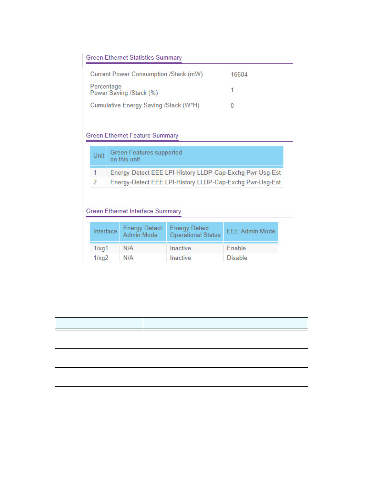
S3300 Smart Managed Pro Switch
Figure 44. Green Ethernet Summary
Table 19, Green Ethernet statistics summary describes the information the Green Ethernet
Statistics Summary table displays.
Table 19. Green Ethernet statistics summary
Field Description
Current Power Consumption The estimated power consumption (in mWatts) by all the ports on
the switch.
Percentage Power Saving/Stack The percentage of power saved on all ports due to the Green
ernet mode(s) being enabled.
Eth
Cumulative Energy Saving per
tack (Watts*Hours)
S
The cumulative energy saved in (Watts * Hour) due to all Green
Ethernet features being enabled.
Configure System Information
73
Page 74

S3300 Smart Managed Pro Switch
Table 20, Green Ethernet feature summary describes the information in the Green Ethernet
feature summary table.
Table 20. Green Ethernet feature summary
Field Description
Unit The unit ID number, which is always 1.
Green Features supported on this
it
un
The Green Ethernet features the switch supports.
Table 21, Green Ethernet interface summary describes the information in the Green Ethernet
interface summary table.
Table 21. Green Ethernet interface summary
Field Description
Interface The interface associated with the rest of the data in the row.
Energy Detect Admin Mode The administrative status of the Energy Detect feature on the
interface.
Energy Detect Operational Status The operational status of the Energy Detect feature on the
interface.
EEE Admin Mode The administrative status of the EEE feature on the interface.
Click Refresh to refre
sh the data on the screen with the current data on the switch.
View and Configure Green Ethernet LPI History
Use this screen to configure and view the Green Ethernet low power idle (LPI) history.
Viewing the Green Ethernet LPI History feature allows you to view the Green Ethernet histo ry
for the switch.
To configure the LPI settings:
1. Select System
> Management > Green Ethernet > Green Ethernet LPI History.
Configure System Information
74
Page 75

S3300 Smart Managed Pro Switch
Figure 45. Green Ethernet LPI History
2. In the Sampling Interval field, specify the frequency, in seconds, at which EEE LPI history.
3. In the Max
Samples to keep field, specify the maximum number of LPI samples to keep in
the history buffer.
4. Click the Ap
To view per-interface LPI history information, select
ply button.
the interface with the information to view
from the Interface list. The screen refreshes and displays the LPI history for the selected
interface.
The following table describes the status fields on the screen.
Table 22. LPI history information
Field Description
Percentage LPI time The percentage of time the switch spent in LPI mode.
Sample No. The current sample number. When the number increases to the
maximum, it rolls over and begins at 1.
Time Since The Sample Was
Recorde
Percentage Time spent in LPI
mo
d
de since last sample
The amount of time that has passed since the last LPI history
sample was recorded. Each time the screen is refreshed it shows
a different time as it reflects the difference in current time and time
at which the sample was recorded.
The percentage of time spent in LPI mode since the last sample
was recorded.
Percentage Time spent in LPI
de since last reset
mo
The percentage of time spent in LPI mode since the switch was
reset.
Configure System Information
75
Page 76

S3300 Smart Managed Pro Switch
Device View
For Device View information, see Device View on page 24.
License
Some switch features require a special license in order to be act ive . If a license is n ot active,
the feature associated with the license is not available and cannot be configured.
To view information about the license key, click System > Licen
The following table describes the non-configurab
Table 23. License Key information
Field Description
License Date The date the license is purchased.
License Copy The number of licenses that e
License Status Indicates whether the license is active or inactive. If a license is
inactive, a license should be purchased and downloaded to the
switch. The license is not activated until the switch reboots.
Description A description of the license key status. If th
field provides information about why it is inactive.
le fields on the License Key page.
xist on the switch.
se > License Key.
e license is inactive, this
To view a list of features on the device that require an active license, click System >
License > Licen
se Features.
Configure System Information
76
Page 77

S3300 Smart Managed Pro Switch
Switch Stack Configuration
Stacking Overview
A stackable switch is a switch that is a fully functional operating standalone, but can also be
set-up to operate together with up to six switches, with this group of switches showing the
characteristics of a single switch while having the port capacity of the sum of the combined
switches.
One of the switches in the stack controls the operation of the stack. This switch is called the
stack manager . The remaining switches in the st ack are st ack members. The st ack members
use stacking technology to behave and work together as a unified system. Layer 2 and above
protocols present the entire switch stack as a single entity to the network.
The stack manager is the single point of stack-wide management. From the stack manager,
you configure the following:
• System-level (global) features that apply to all stack members
• Interface-level features for all interfaces on any stack member
A switch stack is identified in the network by its network IP address. The network IP address
is assigned according to the MAC address of the stack manager. Every stack member is
uniquely identified by its own stack member number.
All stack members are eligible stack managers. If the stack manager becomes unavailable,
the remaining stack members participate in electing a new stack manager from among
themselves. The following factors determine which switch is elected as the stack manager:
• The switch that is manager always has priority to retain the role of manager
• Assigned priority
• MAC address
All stack members must run the same software version to ensure compatibility between st ack
members. The software versions on all stack members, including the stack manager , must be
the same. This helps ensure full compatibility in the stack protocol version among the stack
members. If a stack member is running a software version that is not the same as the stack
manager, then the stack member is not allowed to join the stack.
The stack manager contains the saved and running configuration files for the switch stack.
The configuration files include the system-level settings for the switch stack and the
interface-level settings for all stack members. Each stack member retains a copy of the
saved file for backup purposes.
If the manager is removed from the stack, another member will be elected manager, and will
then run from that saved configuration.
The stack manager switch performs a consistency check to ensure that all units in the stack
are running the same version of agent. Using the information gathered during topology
discovery, the stack manager can determine whether all units are running the same version
of agent. If the versions do not match, then the ports on the subordinate switch will not
become valid for operation. This condition is known as the special stacking mode. You have
Configure System Information
77
Page 78

S3300 Smart Managed Pro Switch
the ability to synchronize the software on the stack unit with the software that is running on
the stack manager. Normally, the software is automatically distributed to all units in the stack
after downloading new code, but there can be instances where a unit with older code is
plugged in to the stack. In this scenario, use the stack firmware synchronization feature to
push the code from the stack manager to the stack members. This ensures that the stack
members are in sync with the rest of the participating switches in the stack. For more
information, see
The stack manager will automatically distribute firmware to subordinate switches when you
upgrade the firmware so that all stack members are synchronized when reloading the stack.
Stack Firmware Synchronization on page 87.
Stack Features
The primary stacking features are as follows:
• Up to 6 switches in a stack
• Single IP Address management through web and SCC
• Manager-member configuration
- Configuration for all units is stored on the manager
- Auto-detection for new members, with synchronization of firmware (upgrade or
downgrade as needed).
• Configuration updates download is supported across the stack through single operation.
• Automatic master fail-over. Fully resilient stack with chain and ring topology.
• Hot swappable (insertion and removal) of stack units
• Stack number information and automatic stacking set-up options
Factory Defaults Reset Behavior
The configurations applied on S3300 would be automatically saved to the flash. The stack
manager automatically distributes the configuration to the stack members. If the stack
manager becomes unavailable, a stack member can become the new stack manager and
apply the configuration that was saved on the original stack manager.
The stack manager initializes the stack using the last saved system configuration that is
stored in its local FLASH. When the stack manager is reset to the factory default settings, the
stack manager applies default settings to all the stack members and resets the stack
including the participating stack members.
Stack Manager Election and Re-Election
The stack manager is elected or re-elected based on one of these factors and in the order
listed:
• The switch that is currently the stack manager
• The switch with the highest stack member priority value
Configure System Information
78
Page 79

S3300 Smart Managed Pro Switch
Note: NETGEAR recommends assigning the highest priority value to the
switch that you prefer to be the stack manager. This ensures that the
switch is re-elected as stack manager if a re-election occurs.
• The switch with the higher MAC address
A stack manager retains its role unless one of these events occurs:
• The stack manager is removed from the switch stack
• The stack manager is reset or powered off
• The stack manager has failed
• The switch stack membership is increased by adding powered-on standalone switch es or
switch stacks
In the case of a manager re-election, the new stack manager becomes available after a few
seconds.
If a new stack manager is elected and the previous stack manager becomes available, the
previous stack manager does not resume its role as stack manager.
Smart M4300/S3300 Stacking Notes and Restrictions
In release 6.6.4, two M4300 models (M4300-12X12F/M4300-24X) are able to be stacked
with S3300 models. This section describes the notes and restrictions when M4300 is mixed
stacking with S3300 running 6.6.4.x firmware.
1. M4300-12X12F/M4300-24X (hereafter referred to as M4300) and S3300 have separate
6.6.4.x images to support this mixed stacking.
a. These switches need to be upgraded to their respective new images before they can
be put into stacking.
b. In order to load the 6.6.4.x image into an M4300 unit running firmware
12.0.0.x/12.0.2.x older than 12.0.2.17, the M4300 should be loaded with a new
12.0.2.x image (12.0.2.17 or newer) first.
c. Once an S3300 unit is running with a 6.6.4 image, it can be brought back to the
M4300 family by directly downloading and activating a 12.0.0.x/12.0.2.x image into
it.
For the procedures regarding upgrading M4300/S3300 firmware, see Smart M4300/S3300
Firmware Upgrade Procedure on page 356.
2. On the two M4300 models, a maximum of four 10G ports (any four from the eight available
ports below) can be configured as stacking ports.
• M4300-24X: port 17–24
• M4300-12X12F: port 9–12 and port 21–24
3. M4300 with 6.6.4.x image scales down to the S330 0 feature set to become part of the
stacking.
a. AVB will not be available even in Standalone mode on M4300.
Configure System Information
79
Page 80

S3300 Smart Managed Pro Switch
b. All stacking functionalities of the S3300 extend to these two M4300 platforms.
However, Non-Stop Forwarding (NSF) is not supported.
c. Either S3300 or M4300 can be stack master or standby.
d. CLI under the console port is not supported.
e. Service port is not supported for management or any other purposes.
4. New features for the M4300 running the Smart 6.6.4.x image are:
• Smart Control Center (SCC) can be used to discover the Smart M4300 and do some
basic settings, the same as can be done on the S3300.
• The Reset button on the front panel of the M4300 models can be used to reset the
unit to the factory default.
- When the Reset button is pressed 2–5 seconds, the switch will simply reset
(reload).
- When the Reset button is pressed over 5 seconds, the switch will clear all
configuration followed by a reload of the factory default settings.
Basic Stack Configuration
Use the Stack Configuration screen to move the Primary Management Unit functionality
from one unit to another. When applied, the entire stack (including all interfaces in the stack)
is unconfigured and reconfigured with the configuration on the new Primary Management
Unit. After the reload is complete, all stack management cap ability must be performed on the
new Primary Management Unit. To preserve the current configuration across a stack move,
save the current configuration to the nvram before performing the stack move. A stack move
causes all routes and Layer 2 addresses to be lost. The system prompts the administrator to
confirm the management move before the changes are applied.
Management Unit Selection
To do basic stack configuration:
1. Click System > Stacking > Basic > Stack Configuration.
2. Select the Management Unit. The Management Unit Selected field displays the Current
Primary Management Unit. You can change it by selecting another unitID listed here.
3. Click the Cancel button to cancel the configuration on the screen and reset the data on the
screen to the latest value of the switch.
4. Click the Apply button to send the updated configuration to the switch. Configuration
changes take effect immediately.
Note: The Move Management operation may cause a change in the system
IP address when the IP address is assigned by a DHCP server.
Configure System Information
80
Page 81

S3300 Smart Managed Pro Switch
Stack Sample Mode
To configure the stack sampling parameters:
1. Select
• Cum
• Histor
the Stack Sample Mode. The global status management mode which can be:
ulative. This tracks the sum of received time stamp offsets cumulatively.
y. This tracks the history of received timestamps.
The factory default is Cumulative.
2. Ente
r a value for Max Samples – the maximum number of samples to keep. The valid
range is 100 to 500. Max Samples applies to History mode.
Figure 46. Configure Stack Sample Mode
3. Click the Apply button to send the updated configuration to the switch. The status
management mode and sample size parameters are applied globally to all units in the stack.
Configuration changes take effect immediately.
4. Click the Cancel
button to cancel the configuration on the screen and reset the data on the
screen to the latest value of the switch.
Stack Configuration
To configure the stack:
1. Select
2. Use the Change
3. Sp
stack.
4. Sp
unit. The range for priority is 0 to 15. The factory default is unassigned. The switch with the
the Unit ID from the displayed list of units in the stack.
Switch ID to field to renumber the switch ID of the selected switch.
ecify t he Switch Type - the type of switch hardware when creating a new switch in the
ecify t he Switch Priority - the priority of a switch to become the primary management
Configure System Information
81
Page 82

S3300 Smart Managed Pro Switch
highest priority value will be chosen to become primary unit. If the value is set to 0, then that
switch unit never participates in Manager Election.
5. Select the Manag
ement Status. Indicates whether the selected switch is the management
unit, or a normal stacking member, or on standby.
6. Click the Appl
y button. The system prompts the administrator to confirm the management
move. Upon administrator confirmation, the entire stack, including all interfaces in the stack,
is unconfigured and reconfigured with the configuration on the new Primary Management
Unit. Configuration changes take place immediately.
7. Click the Can
cel button to cancel the configuration on the screen. The data on the screen is
reset to the latest value of the switch.
8. Click the Up
ter the reload is complete, all stack management capability must be performed on the new
9. Af
date button to update the page with the latest information on the switch.
Primary Management Unit.
The following table describes the non-configurable fields on the Stack Configuration page.
Table 24. Stack Configuration
Field Description
Hardware Management
Preference
Standby Status Identifies the switch that is configured as the standby unit. The
The hardware management preference of the switch. The
hardware management preference can be disabled or unassigned.
e values are:
possibl
Standby. Indicates that the unit is configured as the
• Cfg
standby unit. The unit configured as the standby switch
becomes the stack manager if the current manager fails.
• Opr
• None
Standby. Indicates that this unit is operating a s the
standby unit and the configured standby unit is not part of the
stack.
. The switch is not configured as the standby unit.
Switch Status Displays the status of the selected unit. The possible values are:
• OK
• Unsupp
• Code
• Config Mismatch
• Not Presen
• S
• Upda
orted
Mismatch
t
DM Mismatch
ting Code
Basic Stack Status
The following table describes the non-configurable fields in the Basic Stack Status.
Configure System Information
82
Page 83

S3300 Smart Managed Pro Switch
Ta bl e 25 . Basic Stack
Ta bl e 26 .
Field Description
Unit ID The Unit ID of the specific switch.
Switch Description The description for the unit that
Serial Number The unique box serial number for this switch.
Uptime Displays the relative time since the last reboot of the switch.
Preconfigured Model Identifier Displays the model type assigned by the device manufacturer to
Plugged-in Model Identifier Displays the model type assigned by the device manufacturer to
Detected Code Version Indicates the detected version of code on this unit.
Detected Code in Flash Displays the Release number and version number of the code
SFS Last Attempt Status Displays the Stack Firmware Synchronization last attempt status.
Status
the device.
identify
ntify the plugged-in device.
ide
red in flash.
sto
can be configured by the user.
Click Update to update the page with the latest information on the switch.
Advanced Stack Configuration
Advanced > Stack Configuration uses the same screen as Basic > Stack Configuration
described above.
Advanced Stack Status
Use the Stack Status page to display stack protocol information:
1. Click System > S
2. Select eith
• Select
er the Unit ID or All.
the Unit ID field to display information for the selected unit.
• Select Al
tacking > Advanced > Stack Status.
l to display information for all units.
Configure System Information
83
Page 84

S3300 Smart Managed Pro Switch
Figure 47. Advanced Stack Status
The following table describes the non-configurable Advanced Stack Status data that is
displayed. Click Refresh to update the page with the latest information on the switch.
Table 27. Advanced Stack St atus
Field Description
Unit ID The Unit ID of the specific switch.
Neighbor Unit ID The neighboring unit with which data is exchanged.
Current Current time of heartbeat messag
Average Average time of heartbeat messages received.
Min Minimum time of heartbeat messages received.
Max Maximum time of heartbeat messages received.
Dropped Heartbea t message dropped or lost counter.
e reception.
Clear Sampling Information
To clear the sampling information:
The stack sampling parameters are configured on the Sy
Configuration page. See Stack Sample Mode o
1. Click Syste
See Figure 47 on
2. In
the Clear sampling information > Clear counters field, select the unit to clear the
m > Stacking > Advanced > Stack Status to display the sampling table.
page 84.
n page 81.
counters. Possible choices are None, a unit ID number, or All.
3. Click the Appl
y button to send the updated configuration to the swit ch. Configuration
changes take effect immediately.
stem > Stacking > Basic > Stack
Configure System Information
84
Page 85

S3300 Smart Managed Pro Switch
Advanced Stack-Port Configuration
To configure a Stack-port:
1. Click System > S
Figure 48. Stack-Port Configuration
tacking > Advanced > Stack-port Configuration.
2. Select either the Unit ID or All.
• Select
• Select Al
3. In the Co
the Unit ID field to display information for the selected unit.
l to display information for all units.
nfigured Stack Mode field, specify the operating mode of the port to be either
Ethernet or St ack. The default value for front panel stack mode is Stack. The default value
for back panel stack mode is St ack. The default value for Configured Stack Mode is
Ethernet.
4. In the M4300 models, not
all ports can be configured as stack ports, and only some
particular ports can be configured as stack ports . The maximum is eight stack links.
5. For the predefine
d eight ports on the M4300-24X and M4300-12X12F models, both fiber
and copper stack links are needed. So, the last eight ports are predefined as follows:
or M4300-24X, predefine the last eight ports (port 17 to 24):
a. F
- Port
- Port
b. F
or M4300-12X12F, predefine four fiber ports and four copper ports:
- Port
- Port
6. Ma
nually reboot the switch for the changes to take effect.
The following table describes the non-configurable S
s 17 to 20 are 10G copper.
s 21 to 24 are combo.
s 9 to 12 are 10G fiber
s 12 to 24 are 10G copper.
tack-port Configuration data that is
displayed.
Table 28. Stack-port Configuration
Field Description
Unit ID The Unit ID of the specific switch.
Port Displays the stack port on the given unit.
Running Stack Mode Displays the runtime mode of the stack port.
Link Status Displays the link status (Up/Down) of the port.
Configure System Information
85
Page 86

S3300 Smart Managed Pro Switch
Table 28. Stack-port Configuration (continued)
Field Description
Link Speed (Gbps) Displays the maximum speed of the stack port.
Transmit Data Rate (Mbps) Displays the approximate transmit rate on the stack port.
Transmit Error Rate (Error/s) Displays the number of errors in transmit packets per second.
Total Transmit Errors Displays the total number of errors in transmit packets since
. The counter may wrap.
bootup
Receive Data Rate (Mbps) Displays the approximate receive
Receive Error Rate (Error/s) Displays the number of errors in receive packets per second.
Total Receive Errors Displays the total number of errors in receive packets since
bootup. The counter may wrap.
Link Flaps Displays a stack port counter that increments whenever a stack
ink transitions to the down state.
port l
rate on the stack port.
Advanced Stack-Port Diagnostics
To display Stack-port diagnostics:
Use the Stack-port Diagnostics page to display the diagnostics for all the stack-ports in the
given st
1. Click Syste
2. Select either
ack.
m > Stacking > Advanced > Stack-port Diagnostics.
the Unit ID or All.
• Select the
Unit ID field to display information for the selected unit.
• Select All to d
isplay information for all units.
Figure 49. Stack-port Dia gnostics
Configure System Information
86
Page 87

S3300 Smart Managed Pro Switch
The following table describes the non-configurable Stack-port Diagnostics data that is
displayed.
Table 29. Stack-port Diagnostics
Field Description
Unit ID The Unit ID of the sp
Port Displays the stack port on the given unit.
Port Diagnostics Info Displays three text fields (character strings) populated by the
driver containing debug and status information. The Port
Diagnostics information contains hardware counters; counter
values are displayed in hexadecimal digits.
ecific switch.
Click Update to update the page with the latest information on the switch.
Stack-Port Packet-Path
To display Stack-port Packet-Path:
1. Click System > S
Stack-port packet-path fields. See Figure 49, Stack-port Diagnostics above.
2. T
o navigate, select either the Unit ID or All.
• Select
the Unit ID field to display the packet path starting from the selected unit.
• Select Al
The following table describes the non-configurable packet-path data that is displayed.
Table 30. Stack-port Packet-path
tacking > Advanced > Stack-port Diagnostics to display the
l to display the packet path starting from all the units of the stack.
Field Description
Direction Displays the path direction.
Packet-path Displays the packet path.
Click Update to update the page with the latest information on the switch.
Stack Firmware Synchronization
The Firmware Synchronization feature provides an automatic mechanism to synchronize the
firmware on stack members whose firmware version is different from the version running on
the stack manager. Subject to configuration, this synchronization operation may result in
either an upgrade or a downgrade of firmware on the mismatched stack member . The feature
also checks for boot code version compatibility before starting the upgrade.
By default, the Firmware Synchronization feature is disabled.
Activating the firmware image is not possible if
file is not met by the running boot code on the switch and the auto boot code upgrade feature
is not present.
Configure System Information
the minimum boot code specified in the image
87
Page 88
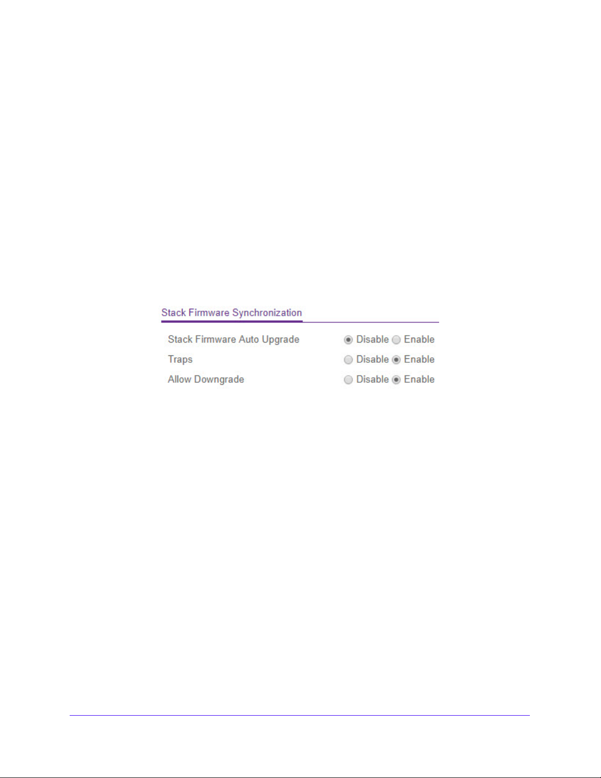
S3300 Smart Managed Pro Switch
The behavior of Firmware Synchronization is the same whether the system is powered on
after connecting all the new members or if a new member is adding during the running
operation of the stack. Stack Firmware Synchronization starts only after the stack manager
selection is complete.
You can disable downgrading the image on a stack member during Firmware
Synchronization op
global and cannot be changed for each individual stack unit.
eration. The Firmware Synchronization configuration parameters are
If the stack member code is mismat
is used for Firmware Synchronization.
The reboot operation is allowed, even though there is a synchronization operation in
progre
intervention by the operator is required to bring the switch back to working condition.
To configure the Stack Firmware Synchronization:
1. Click Syste
Figure 50. Stack Firmware Synchronization
2. Enable or disable the following settings:
ss. In case of firmware corruption during Firmware Synchronization, manual
m > Stacking > Advanced > Stack Firmware Synchronization.
• S
tack Firmware Auto Upgrade. Use this field to enable or disable the Stack
Firmware Synchronization feature. The factory default is Disabled.
• Tr
aps. Use this field to enable or disable the sending of traps during Stack Firmware
Synchronization Start, Failure, and Finish. The factory default is Enabled.
• Allow Downgrade.
stack member if the stack member’s version is newer. The factory default is Enabled.
Use this field to enable or disable downgrading the image on a
ched stack, then the backup image of the stack member
3. Click the Appl
changes take place immediately.
4. Click the Cancel
the screen to the latest value of the switch.
5. Click Up
y button to send the updated configuration to the swit ch. Configuration
button to cancel the configuration on the screen. This resets the data on
date to update the page with the latest information on the switch.
Multiple Stack Links
The S3300 platforms contain two dedicated (non-combo) 10GBaseT copper links (port s) and
2 dedicated SFP+ fiber links. Any of these links can be configured for normal Ethernet
operation or stacking operation. When these links are configured for stacking operation,
Configure System Information
88
Page 89

S3300 Smart Managed Pro Switch
multiple links can be connected to an adjacent unit to form a higher bandwidth stacking
connection. This is referred to as Multiple St ack Links.
The following restrictions and limitations apply when using Multiple Stack Links:
• Fiber link takes precedence over the copper link
• When fiber link is present between the stacked units, traffic is always ca rried throu gh the
fiber link, whether over a single link or over two links in a trunk.
- This happens irrespective of one or two copper links present
- Copper link, in the presence of fiber link, always acts as standby and does not
participate in carrying traffic. However, when the fiber links are down/removed, the
copper link becomes active and starts carrying traffic. This operation (known as
switchover between the links) does not destabilize the stack.
In a multi-unit stack of S3300-52X and/or S3300-52X-PoE+, the following apply:
• One or both copper links between two adjacent S3300 units can be connected to form a
Stack.
• One or both fiber links between two adjacent S3300 units can be connected to form a
stack.
• Both methods above can be used to form a stack of more than two units.
- A Stack of three unit s (Unit-A, Unit-B, Unit-C) can be formed by connecting Unit-A and
Unit-B over two fiber links, and Unit-B and Unit-C over two copper links. This will
make the effective stacking bandwidth between the units ~20G.
- If a combination of one copper and one fiber is chosen between the units (A-B and
B-C), the stack will still form, but the effective stacking bandwidth will be limited to
~10G.
• As an exception to this, if the stack is formed with only S3300-28X and/or
S3300-28X-PoE+ units, the above restriction does not apply.
- The user is free to choose any combination of copper and fiber links to form a stack
without compromising on bandwidth.
- Use of one copper and one fiber to form a stack will still give ~20G bandwidth in case
all the units participating in the stack are S3300-28X and/or S3300-28X-PoE+.
In summary,
• Fiber link takes precedence over the copper link
• When fiber link is present between the stacked units, traffic is always ca rried throu gh the
fiber link, whether over a single link or over two links in a trunk
- This happens irrespective of one or two copper links present
- Copper link, in the presence of fiber link, always acts as standby and does not
participate in carrying traffic. However, when the fiber links are down/removed, the
copper link becomes active and starts carrying traffic. This operation (known as
switchover between the links) does not destabilize the stack.
Configure System Information
89
Page 90

S3300 Smart Managed Pro Switch
PoE
Use this screen to configure a few system-level PoE parameters per unit. In other words, the
parameters are specific to the whole unit, not specific to any port(s).
1. Select System
Figure 51. PoE Basic Configuratio n
> PoE > Basic > PoE Configuration.
2. In the Unit Selection field, select a current PoE unit. You can change the PoE Unit by
selecting another unit ID listed in this field.
3. Configu
re the System Usage Threshold. Set a threshold level at which a trap is sent if
consumed power is greater than threshold power. Possible values are 1% to 99%. The
factory default is 95%.
4. Configu
re Power Manageme nt Mode. Describes or controls the power management
algorithm used by the PSE to deliver power to the requesting PDs. Possible values are:
• Dynamic. Power co
nsumption of each port is measured and calculated in real-time.
The default mode is Dynamic.
• St
atic. Power allocated for each port depends on the type of power threshold
configured on the port.
5. Configu
re Traps. Enable or Disable the activation of PoE traps by selecting the
corresponding check box. The factory default is Enable.
6. Click the Appl
y button to send the updated configuration to the swit ch. Configuration
changes take effect immediately.
7. Click the Can
cel button to cancel the configuration on the screen. The data on the screen is
reset to the latest value of the switch.
8. Click Up
The following table describes the non-configurable PoE Conf
Table 31. PoE Configuration Non-configurable Data
Field Description
Firmware Version Version of the PoE controller’s FW image.
Power Status Indicates the power status.
Total Power (Main AC) Watt Maximum amount of power that is available
Total Power (RPS) Watt Maximum amount of power that is available to the system from an
date to update the page with the latest information on the switch.
iguration data that is displayed.
to the system from the
main AC source to deliver to all ports.
external RPS supply to deliver to all ports.
Configure System Information
90
Page 91

S3300 Smart Managed Pro Switch
Table 31. PoE Configuration Non-configurable Data (continued)
Field Description
Power Source The power source currently being used to deliver power - Main AC
or RPS.
Threshold Power The system can power up one more port if consumed power is less
hreshold Power. In other words, consumed power can be
than T
between Nominal and Threshold Power values. The Threshold
Power value is effected by changing the System Usage Threshold.
There could be a delay in showing the updated values. Click the
Update button to refresh the page again if the Threshold Power is
not changed accordingly. Threshold Power is displayed in
milliwatts (mW).
Consumed Power The total amount of power which is currently being delivered to all
s in milliwatts.
port
Advanced PoE Configuration
The Advanced > PoE Configuration screen displays the same table as the Basic > PoE
Configuration screen described above. However the Advanced screen allows you to
configure a host of PoE parameters specific to port(s) of a specific unit.
Advanced PoE Port Configuration
To configure advanced PoE port settings.
1. Select Sy
The PoE Port Configuration screen displays.
Figure 52. PoE Port Configuration
2. In the Unit Selection field, select a current PoE unit. You can change the PoE Un it by
selecting another unit ID listed in this field.
stem > PoE > Advanced > PoE Port Configuration.
3. Next to Por
t Power, select the Enable button to enable the port to deliver PoE power. The
factory default is Enable.
4. Conf
igure the Port Priority. Use this field to determine which ports can deliver power when
total power delivered by the system crosses a certain threshold. The switch may not be able
to supply power to all connected devices. Priority is used to determine which ports can
Configure System Information
91
Page 92

S3300 Smart Managed Pro Switch
supply power. When port s have the same priority, the lower numbered port will have a higher
priority. Possible priority values are:
• Low. Low priority.
• Medium. Medium priority.
• High. High priority.
• Critical. Critical priority.
The factory default is Low.
5. Select the Power Mode.
• 802.3 af. The PoE port power is limited to IEEE 802.3af mode only. A powered device
(PD) that requires IEEE 802.3at power does not receive power if the port functions in
the IEEE 802.3af mode.
• Legacy. A port is powered using high-inrush current, used by legacy powered devices
(PDs) whose power requirement is greater than 15W at initial power up.
• Pre-802.3at. This means that a port is powered in the IEEE 802.3af mode initially,
then is switched to the high-power IEEE 802.3at mode before 75 msec. This mode
needs to be used if PD is not performing Layer 2 Classification or if the PSE (the
switch) is performing two-event Layer 1 Classification.
• 802.3at. The PoE port power is powered in the IEEE 802.3at mode, and is backward
compatible with IEEE 802.3af. The factory default is 802.3at mode. In the 802.3at
mode, if the switch detects that the attached PD requests more power than the IEEE
802.3af, but is not an IEEE 802.3at Class 4 device, then the PD does not receive
power from the switch.
6. Set the Power Limit Type to control the maximum power that a port can deliver. Use of
these options may lead to a situation where the port reserves a higher amount of PoE power
than the port can actually deliver to a connected PD. This happens when the PD reports
class information incorrectly. Not e that incorrect setting of this field may prevent a PDF from
receiving PoE power from a given port(s).
Possible values are:
• None. This value allows the port to draw up to class 0 max power in case of low
power mode, and up to class 4 max power in case of high power mode.
• Class. This value means that the port power limit is equal to the class of the PD
attached.
• User. This value means that the port power limit is equal to the value specified by
Power Limit.
The factory default is User.
7. In the Power Limit (mw) field, specify the maximum powe r that can be delivered by a port.
The range is 3000–30000 watts with step of 1 milliwatt (mw). The factory default is 30000
mW.
8. In the Detection Type field, select the PD detection mechanism performed by the PSE port.
Possible values are:
• IEEE 802. 4-Point Resistive Detection is done.
Configure System Information
92
Page 93

S3300 Smart Managed Pro Switch
• 4pt 802.3af + legacy. 4-Point Resistive Detection in 802.3af mode, followed by
Legacy Detection, is done.
• Legacy. Only Legacy Detection is done.
The factory default is IEEE 802.
9. Assign a Timer Schedule to the port. Select None to remove the timer schedule
assignment. The factory default is None. See
Timer Schedule on page 132.
10. Click the Apply button to send the updated configuration to the switch. Configuration
changes take effect immediately.
11. Click the Cancel button to cancel the configuration on the screen. The data on the screen is
reset to the latest value of the switch.
12. Click the Power Cycle Port(s ) button to forcibly reset the PSE p ort.
The following table describes the non-configurable PoE Port Configuration data that is
displayed.
Table 32. PoE Port Configuration Non-Configurable Data
Field Description
Port The interface for which data is to be displayed or configured.
High Power Enabled when a particular port supports High Power Mode.
Max Power (mW) The maximum power in milliwatts that can be provided by the port.
Class The class of the Powered Device (PD) defines the range of power
a PD is drawing from the system. Class definitions are:
0. 0.44–16.2 watts
1. 0.44–4.2 watts
2. 0.44–7.4 watts
3. 0.44–16.2 watts
4. 0.44–31.2 watts
Output Voltage Current voltage being delivered to the device in Volt s.
Output Current Current being delivered to the device in mA.
Output Power Current power being delivered to the device in milliwatts.
Temperature The temperature measured at this port of the PoE Controller. The
temperature is measured in degrees Celsius.
Configure System Information
93
Page 94

S3300 Smart Managed Pro Switch
Table 32. PoE Port Configuration Non-Configurable Data (continued)
Field Description
Status Operational status of the port PD detection. Possible values are:
• Disabled. Indicates that no power is being delivered.
• Delivering Power. Indicates that pow er is being drawn by the
device.
• Fault. Indicates a problem with the power.
• Other Fault. Indicates that the port is idle due to an error
condition.
• Requesting Power. Indicates that the port is requesting power.
• Searching. Indicates that the port is not in one of the other
states in this list.
• Test. Indicates that the port is in Test mode.
Fault Status Describes the error description when the PSE port is in fault status.
Possible values are:
• No Error. Specifies that the PSE port is not in any error state
• MPS Absent. Specifies that the PSE port has detected an
absence of main power supply.
• Short. Specifies that the PSE port has detected a short circuit
condition.
• Overload. S pecifies that the PD connected to the PSE port has
tried to provide more power than is permissible by the
hardware.
• Power Denied. Specifies that the PSE port has been denied
power because of a shortage of power, or due to
administrative action.
Configure System Information
94
Page 95

S3300 Smart Managed Pro Switch
SNMP
This section describes how to configure the Simple Network Management Protocol (SNMP)
version 1 and SNMP version 2 information on the switch. For information about configuring
the SNMPv3 administrative profile, see Use SNMPv3 on p
age 29.
The screens you access from the SNMPV1/V2 link a
community information, traps, and trap flags.
llow you to configure SNMPv1/v2
Configure the SNMPv1/v2 Community
Only the communities that you define using this screen will have access to the switch using
the SNMPv1 and SNMPv2c protocols. Only those communities with read/write level access
can be used to change the configuration using SNMP.
Use this screen when you are using the
To add an SNMP community:
1. Select System > SN
Figure 53. SNMP V1/V2 Community Configuration
2. In the Management Station IP field, specify the IP address of the management station.
3. In the Managemen
management station IP address.
MP > SNMP V1/V2 > Community Configuration.
t Station IP Mask field, specify the subnet mask to as s oc ia t e wi t h t he
SNMPv1 and SNMPv2 protocol.
Together, the management station IP and the management station IP mask denote a
ra
nge of IP addresses from which SNMP clients can use that community to access this
device. If either (management station IP or management station IP mask) value is
0.0.0.0, access is allowed from any IP address. Otherwise, every client’s address is
ANDed with the mask, as is the management station IP address; and, if the values are
equal, access is allowed. For example, if the management station IP and management
station IP mask parameters are 192.168.1.0/255.255.255.0, then any client whose
address is 192.168.1.0 through 192.168.1.255 (inclusive) will be allowed access. To allow
access from only one station, use a management station IP mask value of
255.255.255.255, and use that machine’s IP address for client address.
4. In the Co
5. From the Access Mode list, select the access level for this community
Read/Write or Read Only.
6. From the S
mmunity String field, specify a community name.
, which is either
tatus list, enable or disable the community.
Configure System Information
95
Page 96

S3300 Smart Managed Pro Switch
If you select Enable, the community name must be unique among all valid community
names or the set request will be rejected. If you select Disable, the community name will
become invalid.
7. Click the Add but
To modify an existing community:
1. Select the check box next
2. Update
the desired fields.
3. Click the Appl
To delete a community:
1. Select the check box next
2. Click the Delete butto
ton.
to the community.
y button.
to the community to remove.
n.
Trap Configuration
Use this screen to configure settings for each SNMPv1 or SNMPv2 management host that
will receive notifications about traps generated by the device. The SNMP management host
is also known as the SNMP trap receiver.
To add an SNMP trap receiver:
1. Select System > SNMP > SN
MP V1/V2 > Trap Configuration
Figure 54. Trap Configuration
2. In the Recipients IP field, specify the IP addres s in x. x.x .x f or mat to r ec eiv e SN MP tra ps
from this device.
3. From t
• SNMP v1. T
• SNMP v2. T
4. I
he Version list, select the trap version to be used by the receiver.
he switch uses SNMP v1 to send traps to the receiver.
he switch uses SNMP v2 to send traps to the receiver.
n the Community String field, specify the name of the SNMP community that includes the
SNMP management host and the SNMP agent on the device.
5. From
6. Click the Add but
To modify information about an existing SNMP recipient:
1. Select the check box next
2. Update
the Status list, select Enable to send traps to the rece iver.
ton.
to the recipient.
the desired fields.
Configure System Information
96
Page 97

S3300 Smart Managed Pro Switch
3. Click the Apply button.
To delete an SNMP trap recipient:
1. Select
2. Click the Del
the check box next to the recipient to remove.
ete button.
Trap Flags
Use the Trap Flags screen to enable or disable traps the switch can send to an SNMP
manager. W hen the condition ide ntified by an active trap is en countered by the switch, a trap
message is sent to any enabled SNMP trap receivers, and a message is written to the trap
log.
To configure the trap flags:
1. Select System > SN
MP > SNMP V1/V2 > Trap Flags.
Figure 55. SNMP V1/V2 Trap Flags
2. Enable or disable the following system traps:
• Authentication. When
enabled, SNMP traps are sent when events involving
authentication occur, such as when a user attempts to access the device
management interface and fails to provide a valid user name and password.
• L
ink Up/Down. When enabled, SNMP traps are sent when the administrative or
operational state of a physical or logical link changes.
• S
panning Tree. When enabled, SNMP traps are sent when various spanning tree
events occur.
• ACL. Wh
en enabled, SNMP traps are sent when a packet matche s a configured ACL
rule that includes ACL logging.
• PoE. W
3. Click the Ap
hen enabled, SNMP traps are sent when the PoE status changes.
ply button.
Configure System Information
97
Page 98

S3300 Smart Managed Pro Switch
SNMP Supported MIBS
This screen displays a list of all MIBs supported by the switch.
To view the supported MIBs, select Syste
The following table describes t
Table 33. SNMP MIB
Field Description
Name The name of the public or private MIB.
Description A description of the MIB’s purpose.
he fields on the screen.
m > SNMP > SNMP V1/V2 > Supported MIBs.
LLDP
The IEEE 802.1AB-defined standard, Link Layer Discovery Protocol (LLDP), allows stations
on an 802 LAN to advertise major capabilities and physical descriptions. This information is
viewed by a network manager to identify system topology and detect bad configurations on
the LAN.
From the LLDP configuration menu, you can acce
• LLDP Configuration on p
• LLDP Port Settings on p
• LLDP-MED Network Policy o
• LLDP-MED Port Settings on p
age 99
age 100
n page 101
age 102
ss the following links:
• LLDP-MED Neighbors Information on p
• LLDP-MED Neighbors Information on p
• Neighbors Information on p
age 110
LLDP is a one-way protocol; there are no reque
age 103
age 103
st and response sequences. Information is
advertised by stations implementing the transmit function, and is received and processed by
stations implementing the receive function. The transmit and receive functions can be
enabled or disabled separately per port. By default, both transmit and receive are enabled on
all ports. The application is responsible for starting each transmit and receive state machine
appropriately, based on the configured status and operational state of the port.
The Link Layer Discovery Protocol-Media End
point Discovery (LLDP-MED) is an
enhancement to LLDP with the following features:
• Auto-discovery of L
AN policies (such as VLAN, Layer 2 Priority, and DiffServ settings),
enabling plug and play networking.
• Device locat
• Exten
ded and automated power management of Power over Ethernet endpoints.
ion discovery for creation of location databases.
Configure System Information
98
Page 99

S3300 Smart Managed Pro Switch
• Inventory management, enabling network administrators to track their network devices
and determine their characteristics (manufacturer , sof tware and hardware versions, serial
or asset number).
LLDP Configuration
Use the LLDP Configuration screen to specify the global LLDP and LLDP-MED parameters
that are applied to the switch.
To configure global LLDP settings:
1. Select System > LLDP > Basi
Figure 56. LLDP Configuration
c > LLDP Configuration.
2. (Optionally). Configure non-default values for the following LLDP properties.
LV Advertised Interval. The number of seconds between transmissions of LLDP
• T
advertisements.
• Hold
Multiplier . The transmit interval multiplier value, where transmit hold multiplier ×
transmit interval = the time to live (TTL) value the device advertises to neighbors.
• Rei
nitializing Delay. The number of seconds to wait before attempting to reinitialize
LLDP on a port after the LLDP operating mode on the port changes.
• T
ransmit Delay. The minimum number of seconds to wait between transmissions of
remote data change notifications to one or more SNMP trap receivers configured on
the switch.
3. (Optionally)
In the Fast Start Duration field, configure a non-default value.
This value sets the number of LLDP packets sent when the LLDP-MED fast start
mechanism is initialized,
which occurs when a new endpoint device links with the
LLDP-MED network connectivity device.
4. Click the Ap
ply button.
Configure System Information
99
Page 100

S3300 Smart Managed Pro Switch
LLDP Port Settings
Use the LLDP Port Settings screen to specify per-interface LLDP settings.
T o configure LLDP port settings:
1. Select System > LLDP > Adva
Figure 57. LLDP Port Settings
nced > LLDP Port Settings.
2. Select one or more ports to configure.
o configure a single port, select the check box associated with it, or type the port
• T
number in the Go To Interface field and click the Go button.
• T
o configure multiple ports with the same settings, select the check box associated
with each port to configure.
• T
o configure all ports with the same settings, select the check box in the heading row.
3. Use
the lists to configure the LLDP settings for the selected ports:
• Admin S
- Tx
tatus. Select the status for transmitting and receiving LLDP packets:
Only . Enable only transmitting LLDP PDUs on the selected ports.
- Rx Only. Enab
- Tx
and Rx. Enable both transmitting and receiving LLDP PDUs on the selected
le only receiving LLDP PDUs on the selected ports.
ports.
- Disabl
The factory default is Tx
• Mana
ed. Do not transmit or receive LLDP PDUs on the selected ports.
and Rx.
gement IP Address. Choose whether to advertise the management IP address
from the interface. The possible field values are:
- S
top Advertise. Do not advertise the management IP address from the interface.
- Auto A
dvertise. Advertise the current IP address of the device as the
management IP address.
The factory default is Auto Adver
• Notification.
When notifications are enabled, LLDP interacts with the trap manager to
tise.
notify subscribers of remote data change statistics. The default is Disable.
• Optional
TL V(s). Enable or disable the transmission of optional type-length value
(TLV) information from the interface. The factory default is Enable. The TLV
Configure System Information
100
 Loading...