

Page 1

Reference Guide for the Model RT311 and RT314 Internet Access Gateway Routers
NETGEAR, Inc.
4500 Great America Parkway
Santa Clara, CA 95054 USA
Phone 1-888-NETGEAR
SM-RT311NA-4
February 2001
Page 2

© 2001 by NETGEAR, Inc. All rights reserved.
Trademarks
NETGEAR and FirstGear are trademarks Netgear, Inc.
Microsoft, Windows, and Windows NT are registered trademarks of Mi crosoft Corporation.
Other brand and product names are registered trademarks or trademarks of their respective holders.
Statement of Conditions
In the interest of improving internal design, operational function, and/or reliability, NETGEAR reserves the right to
make changes to the products described in this document without notice.
NETGEAR does not assume any liability that may occur due to the use or application of the product(s) or circuit
layout(s) described herein.
Federal Communications Commission (FCC) Compliance Notice: Radio Frequency Notice
This equipment has b een tested and found to co mply with the limits for a Class B digital device, pursuant to
part 15 of the FCC Rules. These limits are desi gned to provide reasonable protection against harmful interference in a
residential installation. This equipment generates, uses, and can radiate radio frequency energy and, if not installed and
used in accordance with the instruc tions, ma y cause harmful interferen ce to radio com munic ations. Ho wever, there is no
guarantee that interference will not occur in a particular installation. If this equipment does cause harmful interference to
radio or television reception, which can be determined by turning the equipment off and on, the user is encouraged to try
to correct the interference by one or more of the following measures:
• Reorient or relocate the receivin g antenna.
• Increase the separation between the equipment and receiver.
• Connect the equipment into an outlet on a circuit different from that to which th e receiver is connected.
• Consult the dealer or an experienced radio/TV technician for help .
EN 55 022 Declaration of Conformance
This is to certify that the Model RT311 and R T31 4 In te rnet Ac cess Gat eway Rout ers ar e shield ed ag ainst th e gene ratio n
of radio interference in accordance with the application of Council Directive 89/336/EEC, Article 4a. Conformity is
declared by the application of EN 55 022 Class B (CISPR 22).
ii
Page 3

Bestätigung des Herstellers/Importeurs
Es wird hiermit bestätigt, daß das Model RT311 and RT314 Internet Access Gateway R outers gemäß der im
BMPT-AmtsblVfg 243/1991 und Vfg 46/1992 aufgeführten Bestimmungen entst ört ist. Das vorschriftsmäßige
Betreiben einige r Ge r ä te (z.B. Testsender) kann jedoch gewissen Beschränkungen unterliegen. Lesen Sie dazu bitte die
Anmerkungen in der Betriebsanleitung.
Das Bundesamt für Zulassungen in der Telekommunikation wurde davon unterrichtet, daß dieses Gerät auf den Markt
gebracht wurde und es ist berechtigt, die Serie auf die Erfüllung der Vorschriften hin zu überprüfen.
Certificate of the Manufacturer/Importer
It is hereby certifie d that the Model RT311 and RT314 I nternet Access Gateway Routers have been suppressed
in accordance with the conditions set out in the BMPT-AmtsblVfg 243/1991 and Vfg 46/1992. The operation of some
equipment (for example, test transmitters) in accordance with the regulations may, however, be subject to certain
restrictions. Please refer to the notes in the operating instructio ns.
Federal Office for Telecommunications Approvals has been notified of the placing of this equipment on the market
and has been granted the right to test the series for compliance with the regulations.
Voluntary Control Council for Interference (VCCI) Statement
This equipment is in the second category (information equipment to be used in a residential area or an adj acent area
thereto) and conforms to the standards set by the Voluntary Control Council for Interference by Data Processing
Equipment and Electronic Office Mach ines aimed at preventing radio interference in such residential areas.
When used near a radio or TV receiver, it may become the cause of radio interference.
Read instructions for correct handling.
Customer Support
Refer to the Support Information Card that shipped with your Model RT311 or RT314 Internet Access Gateway Router.
World Wide Web
NETGEAR maintains a World Wide Web home page that you can access at the universal resource locator (URL)
http://www.netgear.com
or Netscape are required.
. A direct connection to the Internet and a Web browser such as Internet Explorer
iii
Page 4

iv
Page 5

Contents
About This Guide
Technical Support ............................................................................................................ xv
Related Publications ........................................................................................................ xv
Typographical Conventions ............................................................................................xvii
Special Message Formats ..............................................................................................xvii
Chapter 1
Introduction
About the Router ..................... ....... ...... ....... ...... ....... ...... ....... .........................................1- 1
Key Features ..................................................................................................................1-1
Autosensing 10/100 Ethernet ...................................................................................1-3
TCP/IP ............................... ....... ...... ....... ...... ....... ............................................. ...... ...1-3
Security ....................................................................................................................1-4
Easy Installation and Management ..........................................................................1-4
Maintenance and Support ........................................................................................1-5
Chapter 2
Setting Up the Hardware
Package Contents ..........................................................................................................2-1
Local Network Hardware Requirements .........................................................................2-2
PC Requirements ................................. ....... ...... ....... ...... ...... ....... ...... ................ 2-2
Access Device Requirement .............................................................................2-2
The Router’s Front Panel ...............................................................................................2-3
The Router’s Rear Panel ................................................................................................2-5
Connecting the Router ....................................................................................................2-6
Connecting to your Local Ethernet Network .............................................................2-6
Connecting the Model RT311 router to your Local Area Network .....................2-6
Connecting the Model RT314 router to your Local Area Network .....................2-6
Connecting to Your Internet Access Device .............................................................2-7
Connecting the Serial Cable (Optional) ....................................................................2-7
Connecting the Power Adapter ................................................................................2-8
Contents v
Page 6

Verifying Power ........................................................................................................2-8
Chapter 3
Preparing Your Network
Preparing Yo ur Personal Computers for IP Networking .................................................3-1
Configuring Windows 95 or later for IP Networking ........................................................3-2
Configuring TCP/IP Properties .................................................................................3-4
Verifying TCP/IP Properties (Windows) ...................................................................3-4
Configuring the Macintosh for IP Networking .................................................................3-5
Verifying TCP/IP Properties (Macintosh) ..................................................................3-6
Your Internet Account .....................................................................................................3-7
Login Protocols ........................................................................................................3-7
Account Information .................................................................................................3-7
Obtaining ISP Configuration Information (Windows) .........................................3-8
Obtaining ISP Configuration Information (Macintosh) .......................................3-9
Ready for Configuration ........... ....... ............................................. ...... ....... ...... .............. 3 -1 0
Chapter 4
Initial Configuration of the Router
Configuring for Internet Access ......................................................................................4-1
Chapter 5
Advanced Configuration of the Router
System Settings .... ...... ....... ...... ....... ...... ....... ...... ....... ...... ............................................. ...5-1
System Tab ....................... ....... ............................................. ...... ....... ...... ................5-1
Dynamic DNS ...........................................................................................................5-2
Password .................................................................................................................5-2
LAN Setup ......................................................................................................................5-3
DHCP ................................ ................................................................. ......................5-3
LAN TCP/IP ..............................................................................................................5-4
Configuring for Port Forwarding to Local Servers ..........................................................5-6
Local Web and FTP Server Example .................................................................5-7
Local Game Host or Videoconference Example ................................................5-8
Static Routes ..................................................................................................................5-8
Static Route Example .............................................................................................5-10
Chapter 6
Maintenance
System Status ................... ...... ....... ...... ....... ............................................. ...... ....... ...... ...6-1
DHCP Table ....................................................................................................................6-4
vi Contents
Page 7

Software Upgrade ....... ....... ...... ....... ...... ....... ...... ....... ............................................. ...... ...6-4
Erase the Configuration ..................................................................................................6-5
Chapter 7
Using the Manager Interface for Initial Router Configuration
Connecting for Configuration ..........................................................................................7-1
Connecting Through a Serial Port ............................................................................7-2
Connecting Through a Telnet Connection ................................................................7-2
Using the Manager Interface ..........................................................................................7-4
Turning on Power to the Router ...............................................................................7-4
Navigating the Manager ...........................................................................................7-6
Manager Menu Summary ............... ....... ...... ....... ...... ....... ...... ...... .............................7-6
General Setup Menu ................................................................................................7-8
WAN Setup ..............................................................................................................7-9
LAN Setup ..............................................................................................................7-10
LAN Port Filter Setup Menu .............................................................................7-10
TCP/IP and DHCP Setup ................................................................................7-11
Manager Password Setup ..................... ...... ....... ...... ....... ...... ...... ....... .................... 7 -1 3
Chapter 8
Using the Manager Interface to Configure the Router for Internet Access
Internet Access Configuration ........................................................................................8-1
Configuration for Local Servers ......................................................................................8-3
Local Web and FTP Server Example .................................................................8-4
Local Game Host or Videoconference Example ................................................8-5
Setting Static Routes ......................................................................................................8-5
Static Route Example ...............................................................................................8-8
Dynamic DNS ...............................................................................................................8-10
Chapter 9
Using the Manager Interface for System Maintenance
System Status ................... ...... ....... ...... ....... ............................................. ...... ....... ...... ...9-1
Terminal Baud Rate ........................................................ ....... ...... ...................................9-4
Log and Trace .................................................................................................................9-4
View Error Log .........................................................................................................9-4
Syslog and Accounting .............................................................................................9-5
Diagnostic Menu .............................................................................................................9-6
Back Up and Restore Configuration ...............................................................................9-8
Contents vii
Page 8

Backing Up and Restoring the Configuration with a Serial Connection ...................9-8
Backing Up and Restoring the Configuration Using FTP .........................................9-9
Software Update .................................................................... ...... ...... ....... ......................9-9
Updating Router Software Using a Serial Connection .............................................9-9
Updating Router Software Using FTP ....................................................................9-10
Command Interpreter Mode .........................................................................................9-11
Chapter 10
Configuring Filters
Router Filter Structure ..................................................................................................10-1
Configuring a Filter Set .................................................................................................10-2
Configuring a Filter Rule ...............................................................................................10-6
TCP/IP Filter Rule ..................................................................................................10-6
Generic Filter Rule ............ ....... ...... ....... ...... ....... ...... ............................................. .10-9
Applying a Filter Set ...................................................................................................10-10
Default Filters .............................................................................................................10-11
Filter 1: NetBIOS_WAN ........................................................................................10-11
Filter 2: NetBIOS_LAN .........................................................................................10-11
Filter 3: TEL_FTP_WEB_WAN .............................................................................10-11
Chapter 11
Troubleshooting
Basic Functioning ........................... ...... ....... ...... ....... ...... ....... ...... ...... ....... ...... ..............11-1
PWR LED Not On ..................................................................................................11-1
Test LED Never Blinks or LED Stays On ...............................................................11-2
LNK/ACT LEDs Not On ..........................................................................................11-2
Troubleshooting the Web Configuration Interface ........................................................11-2
Troubleshooting the ISP Connection ............................................................................11-3
Troubleshooting a TCP/IP Network Using a Ping Utility ...............................................11-5
Testing the LAN Path to Yo ur Router .....................................................................11-5
Testing the Path from Your PC to a Remote Device ..............................................11-7
Troubleshooting the Manager Interface ........................................................................11-7
Restoring the Default Configuration and Password ......................................................11-8
Using a Serial Connection ......................................................................................11-8
Using FTP ..............................................................................................................11-9
viii Contents
Page 9

Appendix A
Technical Specifications
General Specifications ................................................................................................... A-1
Appendix B
Network and Routing Basics
Basic Router Concepts ............ ....... ...... ....... ...... ....... ...... ....... ...... ...... ............................ B-1
What is a Router? ................................................................................................... B-1
Routing Information Protocol ................................................................................... B-2
IP Addresses and the Internet ................................................................................. B-2
Netmask ............................ ................................................................. ..................... B-4
Subnet Addressing .................................................................................................. B-5
Private IP Addresses ............................................................................................... B-7
Single IP Address Operation Using NAT ................................................................. B-8
MAC Addresses and Address Resolution Protocol ................................................. B-9
Domain Name Server .............................................................................................. B-9
IP Configuration by DHCP .................................................................................... B-10
Ethernet Cabling .......................................................................................................... B-10
Uplink Switches and Crossover Cables .................................................................B-11
Cable Quality ..........................................................................................................B-11
Glossary
Index
Contents ix
Page 10

x Contents
Page 11

Figure 2-1. RT311 Front Panel ...................................................................................2-3
Figure 2-2. RT314 Front Panel ...................................................................................2-3
Figure 2-3. RT311 Rear Panel ...................................................................................2-5
Figure 2-4. RT314 Rear Panel ...................................................................................2-5
Figure 4-1. Login window ...........................................................................................4-2
Figure 4-2. Browser-based configuration main menu ................................................4-2
Figure 4-3. Browser-based Setup Wizard, first screen ...............................................4-3
Figure 4-4. Browser-based Setup Wizard, second screen .........................................4-4
Figure 4-5. Browser-based Setup Wizard, third screen .............................................4-5
Figure 5-1. LAN Setup Menu ......................................................................................5-3
Figure 5-2. Port Forwarding Menu .............................................................................5-6
Figure 5-3. Static Route Summary Table ...................................................................5-8
Figure 5-4. Static Route Entry and Edit Menu ............................................................5-9
Figure 5-5. Static Route Example ............................................................................5-11
Figure 6-1. System Status screen ........................ ...... ....... ...... ...... ....... ...... ....... ...... ...6-1
Figure 6-2. Router Statistics screen ...........................................................................6-3
Figure 6-3. DHCP Table .............................................................................................6-4
Figure 7-1. Start-up Display .......................................................................................7-4
Figure 7-2. Manager Main Menu .......................... ...... ....... ...... ...... ....... ...... ....... ......... 7-5
Figure 7-3. Menu 1 - General Setup ...........................................................................7-8
Figure 7-4. Menu 2 - WAN Setup ...............................................................................7-9
Figure 7-5. Menu 3 - LAN Setup ..............................................................................7-10
Figure 7-6. Menu 23 - System Password .................................................................7-14
Figure 8-1. Menu 4 - Internet Access Setup ...............................................................8-2
Figure 8-2. Menu 15 - SUA Server Setup ..................................................................8-4
Figure 8-3. IP Static Routing Table Example ..............................................................8-6
Figure 8-4. Menu 12.1 - Edit IP Static Route ..............................................................8-7
Figure 8-5. Static Route Example ..............................................................................8-9
Figure 8-6. Menu 1.1 - Configure Dynamic DNS ......................................................8-10
Figure 9-1. Menu 24 - System Maintenance ..............................................................9-2
Figure 9-2. Menu 24.1 - System Maintenance - Status ..............................................9-2
Figure 9-3. Menu 24.4 - System Maintenance - Diagnostic .......................................9-7
Figure 10-1. Menu 21 - Filter Set Configuration .........................................................10-2
Figure 10-2. Menu 21.1 - Filter Rules Summary ........................................................10-3
Figure 10-3. Menu 21.1.1 - TCP/IP Filter Rule ...........................................................10-5
xi
Page 12

Figure B-1. Three Main Address Classes .................................................................. B-3
Figure B-2. Example of Subnetting a Class B Address ............................................. B-5
Figure B-3. Single IP Address Operation Using NAT ................................................ B-8
xii
Page 13

Table 2-1. LED Descriptions .....................................................................................2-4
Table 5-1. Dynamic DNS configuration fields ...........................................................5-2
Table 5-2. DHCP Setup Fields .................................................................................5-4
Table 5-3. LAN TCP/IP Setup Fields .......................................................................5-4
Table 5-4. Port Table Entries (Example) ...................................................................5-7
Table 5-5. Edit IP Static Route Fields ......................................................................5-9
Table 6-1. Menu 3.2 - System Status Fields .............................................................6-2
Table 6-2. Router Statistics Fields ...........................................................................6-3
Table 7-1. Manager Menu Commands ....................................... ....... ...... ....... ...... ...7-6
Table 7-2. Manager Menu Summary .... ...... ....... ...... ............................................. ...7-6
Table 7-3. WAN Setup Fields ...................................................................................7-9
Table 7-4. Menu 3.1 - LAN Port Filter Setup Fields ................................................7-11
Table 7-5. Menu 3.2 - TCP/IP and DHCP Setup Fields .........................................7-12
Table 8-1. Menu 15 Field Entries (Example) .............................................................8-4
Table 8-2. Edit IP Static Route Fields ......................................................................8-7
Table 8-3. Dynamic DNS Configuration Fields ......................................................8-10
Table 9-1. System Maintenance Status ....................................... ....... ......................9-3
Table 9-2. System Maintenance Status Fields ............................ ....... ...... ....... ...... ...9-3
Table 9-3. System Maintenance - Log and Trace Fields ....... ...... ....... ...... ....... ...... ...9-4
Table 9-4. System Maintenance - Sysl og and Accounting Fields ....... ......................9-5
Table 9-5. System Maintenance - Diagnostic Fields ........ ...... ...... ....... ...... ....... ...... ...9-7
Table 10-1. Abbreviations Used in Menu 21.1 - Filter Rules Summary ...................10-3
Table 10-2. Abbreviations Used if Filter Type Is IP ...................................................10-4
Table 10-3. Abbreviations Used if Filter Type Is GEN ...............................................10-4
Table 10-4. TCP/IP Filter Rule Fields ......................................................................10-7
Table 10-5. Generic Filter Rule Fields .....................................................................10-9
Table B-1. Netmask Notation Translation Table for One Octet ................................ B-6
Table B-2. Netmask Formats ........................ ....... ............................................. ...... .. B- 6
Table B-3. UTP Ethernet cable wiring, straight-through ...................... ...... ....... ...... B-10
xiii
Page 14

xiv
Page 15
About This Guide
Congratulations on your purchase of the NETGEAR™ Model RT311 or RT314 Internet Access
Gateway Router.
The Model RT311 and RT314 Internet Access Gateway Routers provide connection for multiple
personal computers (PCs) to the Internet through an external broadband access device (such as a
cable modem or DSL modem) that is normally intended for use by a single PC.
Note:
If you are unfamiliar with networkin g and routing, refe r to Appendi x B, “Network
and Routing Basics,” to become more fami liar with the ter ms and procedures us ed in this
manual.
Technical Support
For help with any techni cal issues, contact Customer Support at 1-888-NETGEAR, or visit us on
the Web at www.NETGEAR.com. The NETGEAR Web site includes an extensive knowledge
base, answers to frequently asked questions, and a means for submitting technical questions
online.
Related Publications
As you read this document, you may be directed to various RFC documents for further
information. An RFC is a Request For Comment (RFC) published by the Internet Engineering
T ask Fo rce (IETF), an ope n orga nization that defines t he archit ecture and operation of the Interne t.
The RFC documents outline and define th e standard proto cols and proced ures for the Internet. The
documents are listed on the World Wide Web at
many other sites worldwide.
About This Guide xv
www.ietf.org
and are mirrored and indexed at
Page 16

Reference Guide for the Model RT311 and RT314 Internet Access Gateway Routers
For more information about address assignment, refer to the IETF documents RFC 1597,
Allocation for Private Internets,
and RFC 1466,
For more information about IP address translation, refer to RFC 1631,
Tr ans lator (NAT)
.
Guidelines for Management of IP Address Space
The IP Netw ork Address
Address
.
xvi About This Guide
Page 17
Reference Guide for the Model RT311 and RT314 Internet Access Gateway Routers
Typographical Conventions
This guide uses the following typographical conventions:
italics
courier font
Initial Caps Menu titles and window and button names.
[Enter] Named keys in text are shown enclosed in square brackets. The notation
[Ctrl]+C Two or more keys that must be pressed simultaneously are shown in text
ALL CAPS DOS file and directory names.
Book titles and UNIX file, command, and directory names.
Screen text, user-typed command-line entries.
[Enter] is use d for the Enter key and the Return key.
linked with a plus (+) sign.
Special Message Formats
This guide uses the following formats to highlight special messages:
Note:
This format is used to highlight information of importance or special interest.
Caution:
equipment failure or loss of data.
This format is used to highlight information that will help you prevent
Warning:
equipment damage.
Danger:
electrical shock if you mishandle the equipment.
About This Guide xvii
This format is used to highlight infor mation about the possibility of injury or
This format is used to alert you that there is the potential for incurring an
Page 18

Page 19

Chapter 1
Introduction
This chapter describes the features of the NETGEAR Model RT311 and RT314 Internet Access
Gateway Routers and discusses planning considerations for installation.
About the Router
The Model RT311 or RT314 Internet Access Gateway Router connects your local area network
(LAN) to the Interne t through a n external si ngle-use r access de vice such a s a cable mode m or DSL
modem.
When personal computers (PCs) on the LAN need to communicate with locations on the Internet,
the PCs send requests to the r out er. The router translates th ose requ ests so that the requests appear
to originate from a single PC, rather than from a network of PCs. The router delivers the requests
to the external access device for transmission to the Internet.
Key Features
The Model RT311 and RT314 Internet Access Gateway Routers are flexible, high-performance,
easy-to-use routers. These routers provide a cost-effective solution for connecting your entire
network to a single-user broadband line, such as a cable modem or DSL modem. With minimum
setup, you can install and use the router within minutes to meet the networking requirements of
your LAN.
Introduction 1-1
Page 20

Reference Guide for the Model RT311 and RT314 Internet Access Gateway Routers
The Model RT311 and RT314 Internet Access Gateway Routers provide the following features:
• Ethernet LAN connection at 10 megabits per second (Mbps) or 100 Mbps
– Internal four port 10/100 switch (Model RT314 router)
– Single 10/100 port (Model RT311 router)
– Autosensing for Ethernet (10BASE-T) or Fast Ethernet (100BASE-Tx) transmissions
– Half-duplex or full-duplex operation
• Ethernet connection to a wide area network (WAN) device, such as a cable modem or DSL
modem
– RJ-45 interface allowing connection to a 10BASE-T device
• Protocol Support
–IP routing
– Dynamic extended Network Address Translation (NAT+) with port forwarding for
operation with a single static or dynamic IP address
– Dynamic Host Configuration Protocol (DHCP) server for dynamically assigning
network configuration information to PCs on the LAN
– DHCP client for dynamically obtaining configuration information fr om the Internet
Service Provider (ISP)
– DNS Proxy for simplified configuration
– PPP over Ethernet (PPPoE) support
• Login capability
– Automatically executes user login for RoadRunner cable modem service or PPP over
Ethernet accounts
• Easy installation and management
– Configure from a web browser
– Built-in Manager i nterf ace for c onfig urati on of advan ced featur es, acce ssibl e by seri al
terminal or Telnet Protocol
•Security
– Network Address Translation (NAT) hides local PCs from the Internet
– Powerful packet filtering capabilities
– Incoming port forwarding for specific services
1-2 Introduction
Page 21

Reference Guide for the Model RT311 and RT314 Internet Access Gateway Routers
• Front panel LEDs for easy monitoring of status and activity
• Flash EPROM for firmware upgrade
• Five-year warranty
• Free technical support seven days a week, twenty-four hours a day
Autosensing 10/100 Ethernet
The Model RT311 and RT314 routers connect to either a 10 Mbps standard Ethernet network or a
100 Mbps Fast Ethernet network. The local LAN interface is autosensing and is capable of
full-duplex operation.
TCP/IP
The Model R T 311 and RT314 ro uters sup port t he Transmission Control Protocol/Inte rnet Pr otocol
(TCP/IP) and Routing Information Protocol (RIP).
For further information about TCP/IP, refer to Appendix B, “Network and Routing Basics.”
• IP Address Masquerading by Dynamic NAT+
The Model RT311 and RT314 routers allow several networked PCs to share an Internet
account using only a single IP address, which may be statically or dynamically assigned by
your Internet service provider (ISP). This technique, an extension of Network Address
Translation (NAT), is also known as IP address masquerading and allows the use of an
inexpensive single-user ISP account.
• Port Forwarding with NAT
Although NAT prevents Internet locations from directly accessing the PCs on the LAN, the
router allows incoming traffic to be forwarded to specific PCs based on the service port
number of the incoming request.
• Automatic Configuration of Attached PCs by DHCP
The Model RT311 and RT314 routers dynamically assign networ k configuration information,
including IP, gateway, and domain name server (DNS) addres se s, to attached PCs on the LAN
using the Dynamic Host Configuration Protocol (DHCP). This fe ature greatly simplifies
configuration of LAN-attached PCs.
• DNS Proxy
When DHCP is enabled and no DNS addresses are specified, the router provides its own
address as a DNS server to the attached PCs. The router obtains actual DNS addresses from
the ISP during connection setup and forwards DNS requests from the LAN.
Introduction 1-3
Page 22

Reference Guide for the Model RT311 and RT314 Internet Access Gateway Routers
• PPP over Ethernet (PPPoE)
PPP over Ethernet is a protocol for connecting remote hosts to the Internet over an always-on
connection by simulati ng a dial-up connection.
Security
The Model RT311 and RT314 routers are equipped with severa l features designed to maintain
security, as described in this section.
• PCs Hidden by NAT
Network address translation (NAT) opens a temporary path to the Internet for requests
originating from the local network. Requests originating from outside the LAN are discarded,
preventing users outside the LAN from finding and directly accessing the PCs on the LAN.
• Packet Filtering
The Model RT311 and RT314 routers provide extensive packet filtering capabilities. Packets
are allowed or discarded based on their source or destination addresses, service port numbers,
or raw data patterns within the packet.
• Port-Address Translation
The Model RT311 and RT314 routers perform port-address tra nslation. Requests originating
from outside the local network are al lo we d to re ach pa rt icu la r loc al workst ations based on the
type of service requested.
Easy Installation and Management
You can install, configure, and operate the Model RT311 or RT314 Internet Access Gateway
Router within minutes after connecting it to the network . T he following features simplify
installation and management tasks:
• Browser-based management
Browser-based configuration allows you to easily configure your router from almost any type
of personal computer , such as W indows, Macintosh, or Linux . A user-friendl y Setup Wizard is
provided and online help documentation is built into the browser-based Web Management
Interface.
• Manager Interface
The Manager interface manages and co nfigures th e router thr ough an easily und erstood screen
process. You can access this inte rface through the MANAGER port on the rear panel of the
router or from across the network, using a Telnet session. The Manager Interface provides
access to advanced features such as custom filters.
1-4 Introduction
Page 23

Reference Guide for the Model RT311 and RT314 Internet Access Gateway Routers
• Visual monitoring
The Model RT311 and RT314 routers’s front panel LEDs provide an easy way to monitor its
status and activity.
Maintenance and Support
NETGEAR offers the following features to help you maximize your use of the Model RT311 and
RT314 routers:
• Flash EPROM for firmware upgrade
• Five-year warranty
Free technical support seven days a week, twenty-four hours a day
Introduction 1-5
Page 24

Reference Guide for the Model RT311 and RT314 Internet Access Gateway Routers
1-6 Introduction
Page 25

Chapter 2
Setting Up the Hardware
This chapter describes the Model RT311 or RT314 Internet Access Gateway Router hardware and
provides instructions for installing it.
Package Contents
The product package should contain the following items:
• Model RT311 or RT314 Internet Access Gateway Router
• AC power adapter, 12 V DC output
• Category 5 (Cat 5) Ethernet cable, straight-through wiring (white)
• Category 5 Ethernet cable, crossover wiring (red) (RT311 only)
Model RT311 and RT314 Resource
•
CD, including:
— This guide
— Application Notes
• Model RT311 and RT314 Internet Access Gateway Router Installation Guide
• Registration and Warranty Card
• Support Information Card
If any of the parts are incorrect, missing, or damaged, contact your NETGEAR dealer. Keep the
carton, including the original packing m aterials, in case you need to return the router for repair.
Setting Up the Hardware 2-1
Page 26

Reference Guide for the Model RT311 and RT314 Internet Access Gateway Routers
Local Network Hard ware Requirements
The Model RT311 or RT314 Internet Access Gateway Router is intended for use in a network of
personal computers (PCs) that are interconnected by twisted-pair Ethernet cables.
PC Requirements
To install and run the Model RT311 and RT314 routers over your network of PCs, each PC must
have the following:
• An installed Ethernet Netwo rk Interface Card (NIC).
• A connection to the network via a hub or switch. If all PCs on the network will not run at the
same speed (10 Mbps or 100 Mbps), you need to use a dual-speed hub or switch. The Model
RT314 router provides a 4-port switch capable of either 10 Mbps or 100 Mbps operation.
Links operating at 100 Mbps must be connected with Category 5 cable.
Access Device Requirement
The shared broadband access device (cable modem or DSL modem) must provide a standard
10BASE-T Ethernet interface.
2-2 Setting Up the Hardware
Page 27
Reference Guide for the Model RT311 and RT314 Internet Access Gateway Routers
The Router’s Front Panel
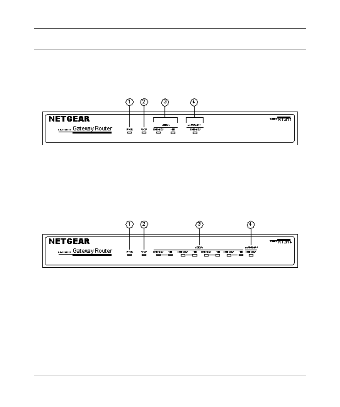
The front panels of the Model RT311 router (Figure 2-1) and Model RT314 router (Figure 2-2)
contain status LEDs.
Key:
1 = PWR (Power) LED
2 = TEST LED
3 = LOCAL LAN LNK/ACT (Link/Activity) and 100M LEDs
4 = INTERNET LNK/ACT (Link/Activity) LED
Figure 2-1. RT311 Front Panel
Key:
1 = PWR (Power) LED
2 = TEST LED
3 = LAN LNK/ACT (Link/Activity) and 100M LEDs
4 = INTERNET LNK/ACT (Link/Activity) LED
Figure 2-2. RT314 Front Panel
Setting Up the Hardware 2-3
Page 28

Reference Guide for the Model RT311 and RT314 Internet Access Gateway Routers
You can use some of the LEDs to verify connections. Table 2-1 lists and describes each LED on
the front panel of the router. These LEDs are gr een when lit.
Table 2-1. LED Descriptions
Label Activity Description
PWR (Power) On
Off
TEST On
Off
Blinking
LOCAL
LNK/ACT
(Link/Activity)
100 (100 Mbps) On
INTERNET LNK/ACT
(Link/Activity)
On
Blinking
Off
On
Blinking
Power is supplied to the router.
Power is not supplied to the router.
The system is not ready or has failed to start up.
The system is ready and running.
The system is initializing.
The LAN port has detected a link with an attached device.
Data is bei ng tranmitted or received by the LAN port.
The LAN is operating at 100 Mbps.
The LAN is operating at 10 Mbps.
The Internet port has detected a link with an attached device.
Data is being tranmitted or received by the Internet port.
2-4 Setting Up the Hardware
Page 29
Reference Guide for the Model RT311 and RT314 Internet Access Gateway Routers
The Router’s Rear Panel
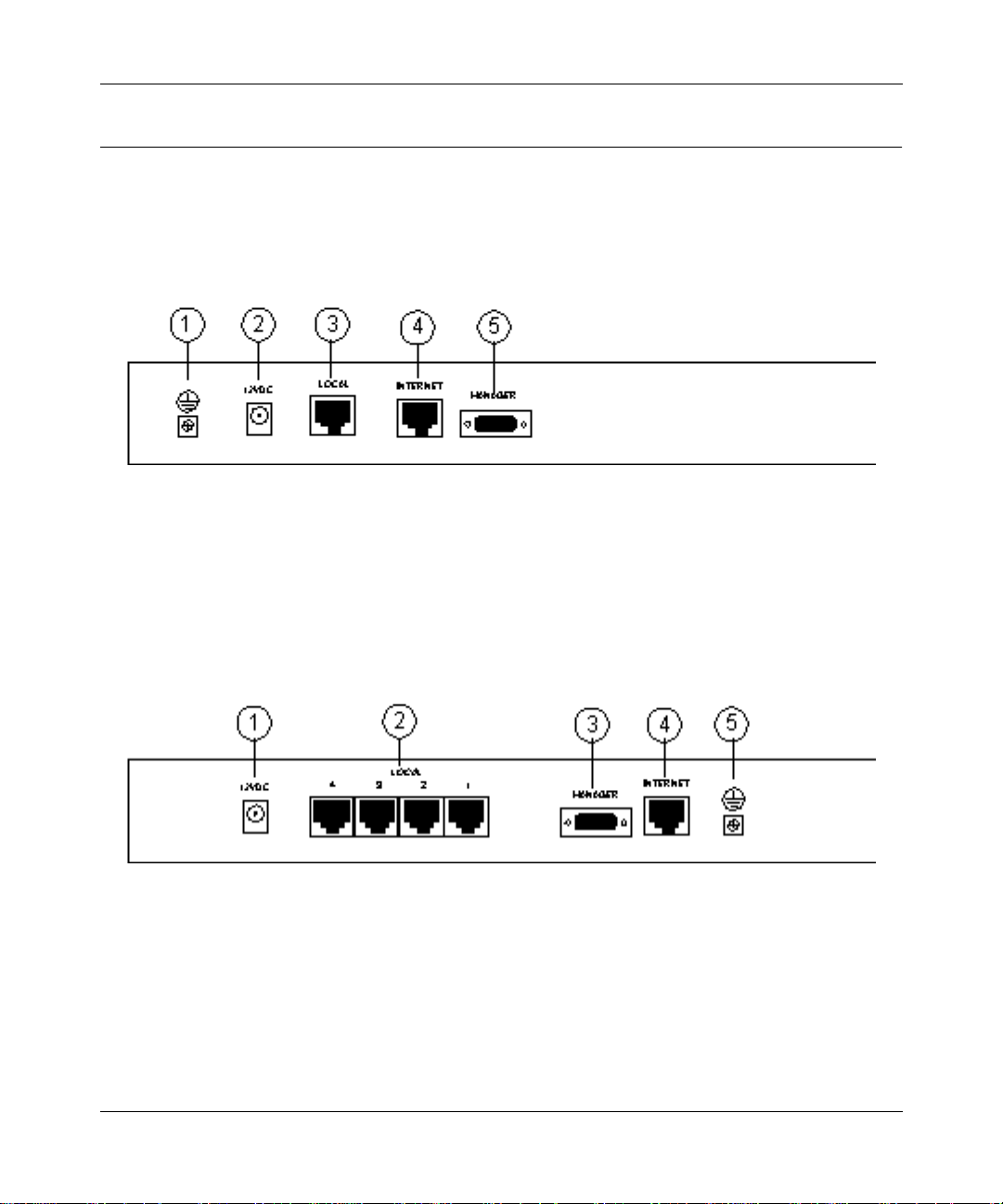
The rear panels of the Model RT311 router and Model RT314 router are shown in Figure 2-3 and
Figure 2-4. Refer to these diagrams to identify all the ports on the router when you attempt to make
any connections.
Key:
1 = Ground
2 = AC adapter outlet for connecting the AC adapter to the router
3 = Local Ethernet port for connecting the router to the loc al LAN
4 = Internet Ethernet port for connecting the router to a cable or DSL modem
5 = RS-232 Manager port for connecting the router to the serial port of a PC
Figure 2-3. RT311 Rear Panel
Key:
1 = AC adapter outlet for connecting the AC adapter to the router
2 = Local Ethernet ports for connecting the router to the local PCs
3 = RS-232 Manager port for connecting the router to the serial port of a PC
4 = Internet Ethernet port for connecting the router to a cable or DSL modem
5 = Ground
Figure 2-4. RT314 Rear Panel
Setting Up the Hardware 2-5
Page 30

Reference Guide for the Model RT311 and RT314 Internet Access Gateway Routers
Connecting the Rout er
Before using your router, you need to do the following:
• Connect your local Ethernet network to the LOCAL port(s) of the router (described next).
• Connect your cable or DSL modem to the INTERNET port of the router (see page 2-7).
• Connect the power adapter (see page 2-8).
Connecting to your Local Ethernet Network
Your local network will attach to the router port or ports marked LOCAL. Because the Model
RT314 router includes a four-port switch whil e the Model RT311 router has a single port for
connection to your local network, the method of connection is different. Follow the procedure
below for your specific mo del .
The LOCAL ports of these rou ters are capable of operation at either 10 Mbps (10BASE-T ) or 100
Mbps (100BASE-Tx), depending on the Ethe rnet interface of the attached PC, hub, or switch. For
any connection which will operate at 100 Mbps, you must use a Category 5 (CAT5) rated cable,
such as the white Ethernet cable included with the router.
Connecting the Model RT311 router to your Local Area Network
The Model RT311 router has a single por t f or connection to your local network. This port is wir ed
as a host rather than a hub, and is intended to connect to a hub or switch in your network. To
connect the Model RT311 router to your LAN:
• Connect the LOCAL po rt of t he r out er to your existing Ethernet hub or swit ch usi ng the white
straight-through Ethernet cable shipped with your router.
To connect the router to a single PC:
• Connect the LOCAL port of the router to the Ethernet port of your PC using the red Ethernet
crossover cable shipped with your router.
If the Ethernet port of your PC op era te s at 100 Mbp s, you must use a Categ ory 5 rate d cable, such
as the red Ethernet cable included with the Model RT311 router.
Connecting the Model RT314 router to your Local Area Network
The Model RT314 router incorporates a four-port switch for connection to your local network. To
connect the Model RT314 router to your LAN:
2-6 Setting Up the Hardware
Page 31

Reference Guide for the Model RT311 and RT314 Internet Access Gateway Routers
• Connect up to four PCs directly to any of the four LOCAL ports of the router using standard
Ethernet cables.
If your local network cons ists of more than four hosts, you will need to connect your router to
another hub or switch:
• Connect any LOCAL por t of you r Model R T 314 rout er to th e UPLINK por t of an Ethernet hub
or switch using standard Ethernet cable.
If the UPLINK port of your hub or switch is selectable for UPLINK or NORMAL operation,
be sure that UPLINK is selected. If the hub or switch does not contain an UPLINK port, you
can connect to one of its normal ports using an Ethernet crossover cable.
Connecting to Your Internet Access Device
To connect the ro uter to the Internet (or WAN):
1.
Connect the router’ s INTERNET port to the 10BASE-T Ether net port on your exi sting Internet
access device (your ca ble modem or DSL modem).
Note:
The attached modem device must provide a standard 10BASE-T Ethernet connection. The
Model RT311 and RT314 routers do not include a cable for this connection. Instead, use the
Ethernet cable provided with your access device or any other standard 10BASE-T Ethernet cable.
If you are using a DSL modem, the modem’s connection to the phone line remains unchanged.
Note:
The Ethernet cable supplied by your ISP for connecting to your cable or DSL modem may
be an Ethernet crossover cable rat her than a st raight- through cable. It is import ant to use th is cable
to connect the modem to your router, not to connect your PCs to your router.
Connecting the Serial Cable (Optional)
In normal operation, you will not nee d a ser ial conn ection to the Manager port. This connection is
used:
• to configure your router using the Manager interface if you cannot use Telnet, or
• to restore the router to factory defaults if you have lost your Manager password.
To connect the serial cable:
1.
Plug one end of the 9-pin RS-232 cable into the MANAGER port.
Setting Up the Hardware 2-7
Page 32

Reference Guide for the Model RT311 and RT314 Internet Access Gateway Routers
2.
Plug the other end into a serial port (such as COM1 or COM2) of your PC.
Note:
You must use a 9-pin to 25-pin adapter if your PC has only a 25-pin port
available.
Connecting the Power Adapter
To connect the router to the power adapter:
1.
Plug the connector o f the powe r adapte r into t he 12 VDC adapter o utlet on the rea r panel of the
router .
2.
Plug the other end of the adapter into a standard wall outlet.
3.
Verify that the PWR LED on the router is lit.
Verifying Power
After connecting the power adapter to the router and a power source, the router powers on
automatica lly. Complete the following steps to verify th at power is correctly applied to the router:
1.
When power is first applied, verify that the PWR LED is on.
2.
Verify that the TEST LED begins to blink within a few seconds.
3.
After approximately 30 seconds, verify that:
a.
The TEST LED is not lit.
b.
The LOCAL LNK/ACT LEDs are lit for any local ports that are connected.
c.
The INTERNET LNK/ACT LED is lit.
If a LNK/ACT LED is lit, a link has been established to the connected device.
4.
If a LOCAL port is connected to a 100 Mbps device, verify that the 100 LED is lit.
You are now ready to begin configuration of your network, as described in the following chapter.
2-8 Setting Up the Hardware
Page 33

Chapter 3
Preparing Your Network
This chapter describes how to prepare your PC network to connect to the Internet through the
Model RT311 or RT314 Internet Access Gateway Router and how to order broadband Internet
service from an Internet service provider (ISP).
Preparing Your Personal Computers for IP Networking
The Model RT311 and RT314 Internet Access Gateway Routers use the Transmission Control
Protocol/Internet Pro toc ol ( TCP/IP). In order to access the Internet through the router, each PC on
your network must have TCP/IP installed and selected as the networking protocol.
Note:
In this chapter, we use the term “PC” to refer to personal comp uters in general, and not
necessarily Windows computers.
Most operating systems include the software components you need to install and use TCP/IP on
your PC:
®
• Windows
establishing a TCP/IP network.
• Windows 3.1 does not include a TCP/IP component. You need to purchase a third-party TCP/
IP application package such as NetManage Chameleon.
• Macintosh Operating System 7 or later includes the software components for establishing a
TCP/IP network.
• All versions of UNIX or Linux include TCP/IP components .
Preparing Your Network 3-1
95 or later (including Windows NT®) includes the software components for
Page 34

Reference Guide for the Model RT311 and RT314 Internet Access Gateway Routers
Follow the instructions provided with your operating system or networking software to install
TCP/IP on your computer. Although TCP/IP is built into the Windows operating system (starting
with Windows 95), you need to enable and configure it as described in “Configuring Windows 95
or later for IP Networking” on page 3-2. To configure the Macintosh, see “Configuring the
Macintosh for IP Networking on page 3-5.
In your IP network, all PCs and the r out er mus t be assign ed IP addresses. Each PC must also have
certain other IP co nfigur atio n infor mation such as a subnet mask (ne tmask), a do main name server
(DNS) address, and a default gate way address. In most cases, you should ins tall TCP/IP so that the
PC obtains its specifi c network config urati on inform ation from a DHCP serve r duri ng bootup . For
a detailed explanation of the meaning and purpose of these configuration items, refer to
“Appendix B, “Networks, Routing, and Firewall Basics.”
The Model RT311 and RT314 routers are shipped preconfigured as a DHCP server. The router
assigns the following TCP/IP configuration information automatically when the PCs are rebooted:
• PC or workstation IP addresses—192.168.0.2 through 192.168.0.31
• Subnet mask—255.255.255.0
• Gateway address (the router)—192.168.0.1
These addresses are part of the IETF-designated private address range for use in private networks.
Configuring Windows 95 or later for IP Networking
As part of the PC preparatio n process, you need to manually install and configure TCP/IP on ea ch
networked PC. Before starting, locate your Windows CD; you may need to insert it during the
TCP/IP installation process.
To configure Microsoft
1.
On the Wi ndo ws t as kbar, click the Start button, poi nt t o Se tt ing s, and then click Control Panel.
2.
Double-click the Network icon.
The Network window opens, which displays a list of installed components:
3-2 Preparing Your Network
®
Windows 95 or later for IP networking:
Page 35

Reference Guide for the Model RT311 and RT314 Internet Access Gateway Routers
You must have an Ethernet adapter, the TCP/IP protocol, and Client for Microsoft Networks.
Note:
It is not necessary to remove any other network components shown in the
Network wind ow in order to install the adap ter, TCP/IP, or Client for Microsof t
Networks.
If you need the adapter:
a.
Click the Add button.
b.
Select Adapter, and then click Add.
c.
Select the manufacturer and model of your Ethernet adapter, and then click OK.
If you need TCP/IP:
a.
Click the Add button.
b.
Select Protocol, and then click Add.
c.
Select Microsoft.
Preparing Your Network 3-3
Page 36

Reference Guide for the Model RT311 and RT314 Internet Access Gateway Routers
d.
Select TCP/IP, and then click OK.
If you need Client for Micr osoft Networks:
a.
Click the Add button.
b.
Select Client, and then click Add.
c.
Select Microsoft.
d.
Select Client for Microsoft Networks, and then click OK.
3.
Restart your PC for the changes to take effect.
Configuring TCP/IP Properties
After the TCP/IP protocol components are installed, each PC must be assigned specific
information about itself and resources that are available on its network. The simplest way to
configure this information is to allow the PC to obtain the information from the internal DHCP
server of the Model RT311 and RT314 routers.
Note:
If an ISP technician configured your PC during the installation of a broadband
modem, or if you configur ed it us ing inst ructions provided by your IS P, you may need t o
copy the current configuration information for use in the configuration of your router.
Refer to “Obtaining ISP Configuration Information (Windows)” on page 3-8 or
“Obtaining ISP Configuration Information (Macintosh)” on page 3-9 for further
information.
If you are using DHCP with the recommended default addresses, you can configure your PCs by
following these steps:
1.
Install TCP/IP on each PC, leaving the PC configured to obtain configuration settings
automatically (by DHCP).
2.
Physically connect the PCs and the router using a hub or a direct connection.
3.
Restart the ro uter and allow it to boot.
4.
Restart each PC.
Verifying TCP/IP Properties (Windows)
After your PC is configured and has rebooted, you can check the TCP/IP configuration using the
Windows 95 and 98 utility
3-4 Preparing Your Network
winipcfg.exe
(for Windows NT systems, use
ipconfig.exe
).
Page 37

Reference Guide for the Model RT311 and RT314 Internet Access Gateway Routers
To check your PC’s TCP/IP configuration:
1.
On the Windows taskbar, click the Start button, and then click Run.
The Run window opens.
Type
winipcfg
, and then click OK.
2.
The IP Configuratio n window opens, which list s (among other things), your IP addr ess, subnet
mask, and default gateway.
3.
Select your Ethernet adapter.
The window is updated to show your sett ings, whi ch should mat ch the val ues below if you are
using the default TCP/IP settings that NETGEAR recommends:
• The IP address is between 192.168.0.2 and 192.168.0.31
• The subnet mask is 255.255.255.0
• The default gateway is 192.168.0.1
Configuring the Macintosh for IP Networking
Beginning with Macintosh Operating System 7, TCP/IP is already installed on the Macintosh. On
each networked Macintosh, you will need to configure TCP/IP to use DHCP by following these
steps:
1.
From the Apple menu, select Control Panels, then TCP/IP.
The TCP/IP Control Panel opens:
Preparing Your Network 3-5
Page 38

Reference Guide for the Model RT311 and RT314 Internet Access Gateway Routers
2.
From the “Connect via” box, select your Macintosh’s Ethernet interface.
3.
From the “Configure” box, select Using DHCP Server.
You can leave the DHCP Client ID box empty.
4.
Close the TCP/IP Control Panel.
5.
Repeat this for each Macintosh on your network.
Verifying TCP/IP Proper ties (Macintosh)
After your Macintosh is configured and has rebooted, you can check the TCP/IP configuration by
returning t o the TCP/IP Control Panel. From the Ap ple menu, select Control Panels, then TCP/IP.
The panel is updated to show your settings, which should match the values below if you are using
the default TCP/IP settings that NETGEAR recommends:
• The IP Address is between 192.168.0.2 and 192.168.0.31
• The Subnet mask is 255.255.255.0
• The Router address is 192.168.0.1
If you do not see these values, you may need to restart your Macintosh or you may need to switch
the “Configure” setting to a different option, then back again to “Using DHCP Server”.
3-6 Preparing Your Network
Page 39

Reference Guide for the Model RT311 and RT314 Internet Access Gateway Routers
Your Internet Account
For access to the Internet, you need to contract with an Internet service provider (ISP) for a
single-user Internet access account using an external broadband access device such as a cable
modem or DSL modem. This modem must be a separate physical box (not a card) and must
provide an Ethernet port intended for connection to a Network Interface Card (NIC) in a PC.
For a single-user Internet account, your ISP supplies TCP/IP configuration information for one
PC. With a typical account, much of the configuration information is dynamically assigned when
your PC is first bo ote d up whi l e co nnec te d to the ISP, and you will not need to know that dynamic
information.
In order to share the Internet connection among several computers, your router takes the place of
the single PC, and you need to configure it with the TCP/IP information that the single PC would
normally use. When the route r’ s INTERNET port is connected to t he broadband modem, the r outer
appears to be a single PC to the ISP. The router then allows the PCs on the local network to
masquerade as the single PC to access the Internet through the broadband modem. The method
used by the router to accomplish this is called Network Address Translation (NAT) or IP
masquerading.
Login Protocols
Some ISPs require a special login protocol. In this case, you will need to know what type of
protocol is used, and you will need a login name and password. The two common protocols are:
• PPP over Ethernet (PPPoE)
Two common PPPoE clients are WinPOET and EntreNet.
• RoadRunner
Not all RoadRunner service areas require a login protocol. If your ISP is RoadRunner, you
should ask whether your PC must run a RoadRunner login program.
After your network and router are configured, the router will perform the login task when needed,
and you will no longer need to login from your PC.
Account Information
Unless these items are dynamically assigned by the ISP, your ISP should give you the following
basic information for your account:
Preparing Your Network 3-7
Page 40

Reference Guide for the Model RT311 and RT314 Internet Access Gateway Routers
• An IP address and subnet mask
• A gateway IP address, which is the address of the ISP’s router
• One or more domain name server (DNS) IP addresses
• Host name and domain suffix
For example, your account’s full server names may look like this:
mail.xxx.yyy.com
In this example, the domain suffix is
xxx.yyy.com
.
If any of these items are dyna mically suppli ed by the IS P, your router automat ically acquir es them.
If an ISP technici an configured your PC during the instal lat i on of the broadband modem, or if you
configured it using ins tr uct io ns provided by your ISP, you need to copy configuration information
from your PC’s Network TCP/IP Properties window (or Macintosh TCP/IP Control Panel) before
reconfiguring your PC for use with the router. These procedures are described next.
Obtaining ISP Configuration Information (Windows)
As mentioned above, you may nee d t o collect configuration information from your PC s o t hat you
can use this information when you conf igu re the Model RT311 and R T31 4 rout er s. Fol lowi ng this
procedure is only necessary when your ISP does not dynamically supply the account information.
To get the information you need to configure the router for Internet access:
1.
On the Wi ndo ws t as kbar, click the Start button, poi nt t o Se tt ing s, and then click Control Panel.
2.
Double-click the Network icon.
The Network window opens, which displays a list of installed components.
3.
Select TCP/IP, and then clic k Properties.
The TCP/IP Properties dialog box opens.
4.
Select the IP Address tab.
If an IP address and subnet mask are shown, write down the information. If an address is
present, your account uses a fixed (stati c) IP address. If no address is present, your account
uses a dynamically-assigned IP address. Click “Obtain an IP address automatically”.
5.
Select the Gateway tab.
If an IP address appears under Installed Gateways, write down the address. This is the ISP’s
gateway address. Select the address and then click Remove to remove the gateway address.
3-8 Preparing Your Network
Page 41

Reference Guide for the Model RT311 and RT314 Internet Access Gateway Routers
6.
Select the DNS Configuration tab.
If any DNS server addresses are shown, write down the addresses. If any information appears
in the Host or Domain information box, write it down. Click Disable DNS.
7.
Click OK to save your changes and close the TCP/IP Properties dialog box.
You are returned to the Network window.
8.
Click OK.
9.
Reboot your PC at the prompt. You may also be prompted to insert your Windows CD.
Obtaining ISP Configuration Information (Macintosh)
As mentioned above, you may need to collect configuration information from your Macintosh so
that you can use this information when you configure the Model RT311 and RT314 routers.
Following this procedure is only necessary when your ISP does not dynamically supply the
account information.
To get the information you need to configure the router for Internet access:
1.
From the Apple menu, select Control Panels, then TCP/IP.
The TCP/IP Control Panel opens, which displays a list of configuration settings. If the
“Configure” setting is “Using DHCP Server”, your account uses a dynamically-assigned IP
address. In this case, close the Control Panel and skip the rest of this section.
2.
If an IP address and subnet mask are shown, write down the information.
3.
If an IP address appears under Router address, write down the address. This is the ISP’s
gateway address.
4.
If any Name Server addresse s are shown, write down the addr esses. Thes e are your IS P’s DNS
addresses.
5.
If any information appear s in the Search domains information box, write it down.
6.
Change the “Configure” setting to “Using DHCP Server”.
Close the TCP/IP Control Panel.
Preparing Your Network 3-9
Page 42

Reference Guide for the Model RT311 and RT314 Internet Access Gateway Routers
Ready for Configuration
After configuring all of your PCs for TCP/IP networking and connecting them to the LOCAL
network of your Model RT311 and RT314 routers, you are ready to access and configure the
router. Proceed to the next chapter.
3-10 Preparing Your Network
Page 43

Chapter 4
Initial Configuration of the Router
This chapter describes how to perform the initial configuration of your Model RT311 or RT314
Internet Access Gateway Router using the Setup Wizard, which walks you through the
configuration process.
Configuring for Internet Access
In order to use the browser-based Web Configuration Mana ger, your PC must have a web browser
program installed such as Microsoft Internet Explorer or Netscape Navigator. Because the
Configuration Manager uses Java, your Web browser must be Java-enabled and support HTTP
uploads. NETGEAR recommends using Netscape Navigator 3.0 or above. Free browser pro gra ms
are readily available for Windows, Macintosh, or UNIX/Linux.
To configure for Internet access using your browser:
1.
Turn on the router and w ait for initialization to comp lete.
Allow at least one minute and verify that the TEST LED is off.
2.
Reboot your PC to obtain DHCP configuration from the router.
3.
Launch your web browser.
4.
In the Address box of your browser, type
Initial Configuration of the Router 4-1
http://192.168.0.1
and press ENTER.
Page 44

Reference Guide for the Model RT311 and RT314 Internet Access Gateway Routers
A login window opens as shown in Figure 4-1 below:.
Figure 4-1. Login window
Type
admin
in the User Name box,
5.
1234
in the Password box, and then click OK.
If your router passwor d was previously changed, enter the current password.
6.
In the opening screen, shown in Figure 4-2, select WIZARD SETUP.
Figure 4-2. Browser-based configuration main menu
4-2 Initial Configuration of the Router
Page 45

Reference Guide for the Model RT311 and RT314 Internet Access Gateway Routers
7.
In the first Wizard screen, enter your account’s Host Name and Domain Name, as shown in
Figure 4-3 below:
Figure 4-3. Browser-based Setup Wizard, first screen
These parameters may be necessar y to acc ess your I SP’s services such as mail or news serve rs.
If you leave the Domain Name field blank, the router will attempt to learn the domain
automatica lly from the ISP. If this is not successful, you will need to enter it manually.
Initial Configuration of the Router 4-3
Page 46

Reference Guide for the Model RT311 and RT314 Internet Access Gateway Routers
8.
Click on Nex t to go to the ISP Parameters screen, shown in Figure 4-4 below:
Figure 4-4. Browser-based Setup Wizard, second screen
This screen determines whether a login program will be run.
a.
If your service provide r does not requi re a logi n progra m, leave Enc apsula tion as Etherne t
and proceed to Step 9.
b.
If your service provider uses PPP over Ethernet (PPPoE), select Encapsulation as PPPoE,
and enter these additional parameters:
• If your connection s upports mult iple ISPs, enter the Se rvice Name of t he one you use.
Otherwise leave Service Name blank.
• Enter the PPPoE login user name and password pr ovided by your ISP. These fields are
case sensitive.
• If you wish to change the login timeout, enter a new value in seconds.
Proceed to Step 9.
c.
European versions only: If your service provider uses Alcatel's ANT (ADSL Network
Termination) with PPTP as a login method, select Encapsulation as PPTP, and enter these
additional parameters:
• Enter the PPTP login user name and password provided by your ISP. These fields are
case sensitive.
• If you wish to change the login timeout, enter a new value in seconds.
4-4 Initial Configuration of the Router
Page 47

Reference Guide for the Model RT311 and RT314 Internet Access Gateway Routers
• If provided by your ISP, ente r your PPTP IP Address and the Server IP Address of
their PPTP Server.
• If provided by your ISP, enter the Connection ID/Name for your service. Otherwise
leave this field blank.
Proceed to Step 9.
d.
If your service provider is RoadRunner AND you are required to run a RoadRunner login
program, leave Encapsulation as Ethernet and select Service Type as either RR-Manager
or RR-Toshiba. Enter these additional parameters:.
• If your cable modem is Toshiba, select RR-Toshiba. Otherwise select RR-Manager.
• Enter the user name and password provided by your ISP. These fields are case
sensitive.
• If RoadRunner provided an authentication server address, enter it as Login Server IP
address. Otherwise, leave this field as 0.0.0.0.
Not all RoadRunner regions require a login program. If your region does not require a
login, leave Service Type as Standard.
9.
Click on Next to go to the final Wizard screen shown in Figure 4-5 below.
Figure 4-5. Browser-based Setup Wizard, third screen
This screen provides setup for the following parameters:
Initial Configuration of the Router 4-5
Page 48

Reference Guide for the Model RT311 and RT314 Internet Access Gateway Routers
a.
WAN IP Address Assignment: Unle ss you r ISP h as assig ned a f ixed permanen t IP addr ess
for your use, select "Get automatically from ISP". Otherwise, enter your IP Address,
Subnet Mask, and the IP Address of your ISP’s gateway router.
b.
DNS Server Address Assignment: If you know that your ISP does not automatically
transmit DNS addresses to the ro uter duri ng login, sel ect “Use t his serv er” and ent er the IP
address of the ISP’s DNS server.
A DNS server is a host on the Internet that translates Internet names (such as www
addresses) to numeric IP a ddresses. Typically your ISP transfers the IP addresses of one or
two DNS servers to your router during login. If the ISP does not transfer an address, you
must obtain it from the ISP and enter it manually here. If you enter an address here, you
should reboot your PCs after configuring the router.
c.
WAN MAC address: If your ISP allows access by only one specific PC’s Ethernet MAC
address, select "Spoof this PC’s MAC address" and enter the IP address of that PC.
• For convenience, t he IP ad dress of the PC you are now u sing shoul d alrea dy appear. If
this is not the PC whose MAC address is to be used, enter that PC's IP address.
• Some ISPs w ill register the Ethernet MAC address of the networ k interface card in
your PC when your account is first ope ned. They will th en only accept traf fic from the
MAC address of that PC. This featur e a ll ows your router to masquerade as that PC by
using its MAC address.
10.
Click on Finish.
11.
Click on the NETGEAR website address to test your Internet connection.
If the NETGEAR website does not appear within one minute, re fer to Chapter 11,
“Troubleshooting”.
Your router is now configured to provide Internet access for your network. When your router and
PCs are configured correctly, your router automatically accesses the Internet when one of your
LAN devices requires access. It is not necessary to run a dialer application such as Dial-Up
Networking or RoadRunner Logi n to connect, log in, or disc onnect. These func tions are performed
by the router as needed.
To access the Internet from any PC connected to your router, launch a browser such as Microsoft
Internet Explorer or Netscape Navigator. You should see the router’s Internet LED blink,
indicating communication to the ISP. The browser should begin to display a Web page.
4-6 Initial Configuration of the Router
Page 49

Chapter 5
Advanced Configuration of the Router
This chapter describes how to configure the advanced features of your Model RT311 or RT314
Internet Access Gateway Router. These featur es can be found by clicking on the Advanced
heading in the Main Me nu of the browser interface.
System Settings
The first feature category under the Advanced heading is System settings. These are general
purpose settings.
System Tab
The System Tab contains fields for setting the System (Host) Name and Domain Name. These
parameters may be necessary to access your ISP’s services such as mail or news servers.
• System Name
This is the host or account name gi ven by yo ur ISP for nami ng your PC. It is o ften the primar y
email name of your account.This name can be up to 30 alphanumeric characters long. Spaces
are not allowed, but dashes "-" and underscores "_" are accepted.
• Domain Name
This is the extended domain suffix that follows your ISP server names. For example, if your
ISP’s mail server is mail.sfbay.myISP.com, then your Domain Name is sfbay.myISP.com.
Advanced Configuration of the Router 5-1
Page 50

Reference Guide for the Model RT311 and RT314 Internet Access Gateway Routers
Dynamic DNS
Your router supports Dynamic Domain Name Service (DDNS). In a Dynamic DNS service, an IP
registry server provi des a public cent ral dat abase where dynamicall y-ass igned IP ad dre sses can be
stored and retrieved by hostname lookup. The Dynamic DNS server also stores
password-protected e-mail addresses along with IP addresses and hostnames and accepts queries
based on e-mail addresses.
To utilize this service, you must register with the Dynamic DNS service provider, who will give
you a password or key. At this time, the Model RT311 and RT314 routers only support DynDNS
service. For more information, visit www.dyndns.org.
The configuration fields for Dynamic DNS are shown in Table 5-1:
Table 5-1. Dynamic DNS configuration fields
Field Description
Active Use this field to activate or deactivate dynamic DNS registration.
Service Provider Select a dynamic DNS servic e provider.
Host Name Enter the static host name that will link to your dynamic IP address.
E-Mail Address Enter your email address for administrative contact.
User Enter the user name of your dynamic DNS account.
Password Enter the password of your dynamic DNS account.
Enable Wildcard DynDNS.org allows the use of wildcards in resolving your URL.
Enabling the wildcard feature for your host will cause
*.yourhost.dyndns.org to be aliased to the same IP address as
yourhost.dyndns.org.
Password
Select the Password tab to change your router’s management password. This is the password to
access the router for configuration, not for Internet access. To change the password, first enter the
old password, and then enter the new password twice.
5-2 Advanced Configuration of the Router
Page 51

Reference Guide for the Model RT311 and RT314 Internet Access Gateway Routers
LAN Setup
The second feature category under the Advanced heading is LAN Setup. This menu allows
configuration of LAN IP services such as DHCP and RIP. From the Main Menu of the browser
interface, under Advanced, click on LAN to view the LAN Setup menu, shown in Figure 5-1
Figure 5-1. LAN Setup Menu
DHCP
The Model RT311 and RT314 routers have the capability to act as a DHCP server, allowing them
to assign IP, DNS, and default gateway addresses to attached PCs. The assigned default gateway
address is the LAN address of the router. IP addresses will be assigned to the attached PCs from a
pool of addresses specified in this menu. Each pool address is tested before it is assigned to avoid
duplicate addresses on the LAN.
See “IP Configuration by DHCP” on page B-10 for an explanation of DHCP and information
about how to assign IP addresses for your network.
For most applications, the default DHCP and TCP/IP settings of the router are satisfactory. These
default settings are:
• DHCP server enabled with 32 client addresses starting from 192.168.0.1.
Advanced Configuration of the Router 5-3
Page 52

Reference Guide for the Model RT311 and RT314 Internet Access Gateway Routers
Table 5-2 lists and describes the fields to use for setting up DHCP parameters..
Table 5-2. DHCP Setup Fields
Field Description
DHCP Server: If this box is checked, the router acts as a DHCP server.
If this box is cleared, the router’s DHCP server is disabled.
Pool Starting Address The beginning of the range of IP addresses to assign.
Count The number of sequential addresses available for assignment to
attached hosts. The maximum is 32.
Primary DNS Server If you want the router to provide the Primary DNS Server address to
attached hosts, enter t he DNS ad dress in th is fie ld. If thi s field is 0.0. 0.0,
the router assigns its own address as DNS Server , a nd perfo rm s a D NS
Proxy if it can obtain a DNS address from the ISP.
Secondary DNS Server If you want the router to assign the Secondary DNS Server address
to attached hosts, enter the address in this field.
LAN TCP/IP
Table 5-3 lists and describes the fields to use for setting up TCP/IP parameters for the LAN...
Table 5-3. LAN TCP/IP Setup Fields
Field Description
TCP/IP Setup:
IP Address Enter the IP address of the LAN interface of the router in dotted-decimal
notation (four 8-bit numbers, between 0 and 255, separated by periods,
for example, 192.168.0.1). Every device on the TCP/IP network must
have a unique IP address.
IP Subnet Mask An IP address consists of two parts, the network ID and the host ID. The
IP Subnet Mask specifies the network ID portion of the address, written
in dotted-decimal notatio n. The rou ter autom atically calculates this m ask
for the class of the IP address that you assign. Unless you have a
special need for subnetting, use the default subnet mask calculated by
the router. All hosts on the LAN segment should use the same mask.
5-4 Advanced Configuration of the Router
Page 53

Reference Guide for the Model RT311 and RT314 Internet Access Gateway Routers
Table 5-3. LAN TCP/IP Setup Fields (continued)
Field Description
RIP Direction This parameter determines how the router handles RIP (Routing
Information Protocol). RIP allows the router to exchange routing
information with other routers. If set to None (default), the router does
not participate in any RIP exchange with other routers. If set to Both, the
router broadcasts the routing table of the router on the LAN and
incorporates RIP broadcasts by other routers into its routing table. If set
to In Only, the router broadcasts its routing table on the LAN. If set to
Out Only, the router broadcasts its routing table, but it ignores any RIP
broadcast packets that it receives. Usually, you should leave this
parameter at the default (None)
RIP Version This field determines the format and broadcasting method of any RIP
(Routing Information Protoc ol) transmiss ions by the router . The following
RIP options are supported by the Model RT311 router:
• RIP-1—The router sends RIP-1 messages only.
• RIP-2B—The router sends RIP-2 messages in broadcast format.
• RIP-2M—The router send s RIP-2 messag es in multicast format.
For most applications, the recommended version is RIP-1.
Multicast Some streaming media applications (e.g. Cisco IP/TV, RealPlayer) now
support IP Multicast. To enable Multicast routing, select either IGMP-v1
or IGMP-v2.
.
Note:
If you change the LAN IP address of the router while connected through the
browser or Telnet, you will be disconnected. You must then open a new connection to
the new IP address and log in again.
Advanced Configuration of the Router 5-5
Page 54

Reference Guide for the Model RT311 and RT314 Internet Access Gateway Routers
Configuring for Port Forwarding to Local Servers
Although the router cause s your entire local network to appear as a single machine to th e I nte rne t,
you can make local servers for dif ferent ser vices (f or example, FTP or HTTP) visible an d availabl e
to the Interne t. This is done using the PORTS menu. From th e Main Menu of the browser
interface, under Advanced, click on PORTS to view the port forwarding screen, shown in
Figure 5-2
Figure 5-2. Port Forwarding Menu
Requested services ar e identi fied by port nu mbers in an incoming I P packet. For example, a pa cket
that is sent to the external IP address of your router and destined for port number 80 is an HTTP
(Web server) request, and port 21 is an FTP request. Examples of port numbers are shown at the
top of the PORTS menu, although you are not limited to these choices. See IETF RFC1700,
“Assigned Numbers,” for port numbers for common protocols..
Note:
Many residential broadband ISP accounts do not allow you to run any server
processes (such as a Web or FTP server) from your location. Your ISP may periodically
check for servers and may suspend your account if it discovers any active services at
your location. If you are unsure, refer to the Acceptable Use Policy of your ISP.
5-6 Advanced Configuration of the Router
Page 55

Reference Guide for the Model RT311 and RT314 Internet Access Gateway Routers
Use the PORTS menu to configure the router to forward incoming protocols to IP addresses on
your local network based on the port number . In addition to servers for specific protoc ols , yo u ca n
also specify a Default (also called DMZ) Server to which all other incoming protocols are
forwarded. To configure port forwarding to a local server:
1.
Enter the Port Number in an unused Port # box.
2.
Enter the IP address of the local server in the corresponding Server IP Address box.
3.
Click Apply at the bottom of the menu.
Local Web and FTP Server Example
If a local PC, with a private address of 192.168.0.33, acts as a Web and FTP server, configure the
POR TS menu to forward ports 80 (HTTP) and 21 (FTP) to l oca l address 192.168.0.33 as shown in
Table 5-4.
Table 5-4. Port Table Entries (Example)
Port # Server IP Address
Default 0.0.0.0
80 (HTTP) 192.168.0.33
21 (FTP) 192.168.0.33
In order for a remote user to access this server from the Internet, the remote user must know the IP
address that has been as si gned by your ISP. If this address is 172.16.1.23, for examp le, an In ternet
user can access your Web server by directing the browser to http://172.16.1.23. The assigned IP
address can be found in the Maintenance Status Menu, where it is shown as the WAN IP Address.
Some consid erations for this application are:
• If your account’s IP address is assigned dynamically by your ISP, the IP address may change
periodically as the DHCP lease expires.
• If the IP address of t he loca l PC is ass igned by DHCP, it may ch ange when t he PC is reb ooted.
To avoid this, change the configuration of your PCs to use fixed private addresses rather than
DHCP-assigned addresses.
• Local PCs must access t he local ser ver using th e PCs’ local LAN addr ess (192.168 .0.33 in this
example). Attempts by local PCs to access the server using the external IP address
(172.16.1.23 in this example) will fail.
Advanced Configuration of the Router 5-7
Page 56

Reference Guide for the Model RT311 and RT314 Internet Access Gateway Routers
Local Game Host or Videoconference Example
Some online games and videoc onferencing applications are incompatible with NAT. The
Model Model RT311 and RT314 routers are programmed to recognize some of these
applications and to work properly with them, but there are other applications that may not
function well. In some cases, one local PC can run the application properly if that PC’s IP
address is entered as the default in the PORTS Menu. If one local PC acts as a game or
videoconference host, enter its IP address as the default.
Static Routes
The fourth feature category under the Advanced heading is Static Route, which allows
configuration of additional routing information. Under normal ci rcumstances, the router has
adequate routing information after it has been configured for Internet access, and you do not need
to configure additional static routes. You must configure static routes only for unusual cases such
as multiple routers or multiple IP subnets located on your network.
From the Main Menu of the browser interface, under Advanced, click on Static Route to view the
Static Route menu, shown in Figure 5-3.
Figure 5-3. Static Route Summary Ta ble
5-8 Advanced Configuration of the Router
Page 57

Reference Guide for the Model RT311 and RT314 Internet Access Gateway Routers
To add or edit a Static Route, select a number and click the Edit button to open the Edit Menu,
shown in Figure 5-4
Figure 5-4. Static Route Entry and Edit Menu
Table 5-5 lists and describes the fields for the IP Static Route Edit menu.
Table 5-5. Edit IP Static Route Fields
Field Description
Route Name Enter a descriptive name for this route for identification purposes only.
Active Use this field to activate or deactivate this static route.
Destination IP Address Enter the IP network address of the final destination. Routing is always based
on network number. If you need to specify a route to a single host, use a
subnet mask of 255.255.255.255 in the subnet mask field to force the
network number to be identical to the host ID.
IP Subnet Mask Enter the subnet mask for this destination.
Gateway IP Address Enter the IP address of the gateway to the destination network. The gateway
is the next router that your router contacts in order to forward packets to the
destination. On the LAN, the gate way must be a ro uter on the same segment
as the router. Over the WAN, the gateway will be the IP address of the rou ter
at your ISP.
Advanced Configuration of the Router 5-9
Page 58

Reference Guide for the Model RT311 and RT314 Internet Access Gateway Routers
Table 5-5. Edit IP Static Route Fields (continued)
Field Description
Metric Enter the cost in ‘hops’ of transmission for routing purposes. IP routing uses
hop counts as the measurement of cost, with a minimum of 1 for directly
connected networks. Enter a number that approximates the cost for this link.
The number does no t have to be precise , but i t must b e betw een 1 and 16. In
practice, 2 or 3 is usually a good number.
Private Use this field to determine whether the router includes the route to this
remote node in it s R I P bro adc as ts. If set to Yes, thi s rout e is kept private and
not included in any RIP broadcast. If set to No, the route to this remote node
is propagated to other hosts through RIP broadcasts.
Static Route Example
As an example of when a static route is needed, consider the following case:
• Your primary Internet access is through a cable modem to an ISP.
• You have an ISDN router on your home network for connecting to the company where
you are employed. This rout er’s address on your LAN is 192.168.0.100.
• Your company’s network is 134.177.0.0.
When you first configur ed your r outer, t wo implic it st atic routes were cr eated . A defaul t rout e was
created with your ISP as the gateway, and a second static route was created to your local network
for all 192.168.x.x addresses. With this configuration, if you attempt to access a device on the
134.177.0.0 network, your router will forward your request to the ISP. The ISP forwards your
request to the company where you are employed, and the request will likely be denied by the
company’s firewall.
5-10 Advanced Configuration of the Router
Page 59

Reference Guide for the Model RT311 and RT314 Internet Access Gateway Routers
In this case you must define a static route, telling your router that 134.177.0.0 should be accessed
through the ISDN router at 192.168.100. The static route would look like Figure 5-5.
Figure 5-5. Static Route Example
In this exampl e:
• The Destination IP Address and IP Subnet Mask fields specify that this static route applies to
all 134.177.x.x addresses.
• The Gateway IP Address fields specifies that all traffic for these addresses should be
forwarded to the ISDN router at 192.168.0.100.
• A Metric value of either 1 or 2 will work.
• Private is selected only as a precautionary security measure in case RIP is activated.
Advanced Configuration of the Router 5-11
Page 60

Reference Guide for the Model RT311 and RT314 Internet Access Gateway Routers
5-12 Advanced Configuration of the Router
Page 61

Chapter 6
Maintenance
This chapter describes how to use the maintenance features of your Model RT311 or RT314
Internet Access Gateway Router. These featur es can be found by clicking on the Maintenance
heading in the Main Me nu of the browser interface.
System Status
The System Status menu provides a limited amount of status and usage information. From the
Main Menu of the browser interface, click on Maintenance, then select System Status to view the
System Status screen, shown in Figure 6-1
.
Figure 6-1. System Status screen
Maintenance 6-1
Page 62

Reference Guide for the Model RT311 and RT314 Internet Access Gateway Routers
This screen shows the following parameters:
Table 6-1. Menu 3.2 - System Status Fields
Field Description
System Name This field displays the Host Name assigned to the router.
Router Firmware Version This field displays the router firmware version.
WAN Port These parameters apply to the Internet (WAN) port of the router.
IP Address This field displays the IP add res s be ing us ed b y th e Inte rne t (WAN) port
of the router. If no address is shown, the router cannot connect to the
Internet.
IP Subnet Mask This field displays the IP Subnet Mask being used by the Internet (WAN)
port of the router.
DHCP If set to None, the router is configured to use a fixed IP address on the
WAN.
If set to Client, the router is configured to obtain an IP address
dynamically from the ISP.
LAN Port These parameters apply to the Local (WAN) port of the router.
IP Address This field displays the IP address being used by the Local (LAN) port of
the router. The default is 192.168.0.1
IP Subnet Mask This field displays the IP Subnet Mask being used by the Local (LAN)
port of the router. The default is 255.255.255.0
DHCP If set to None, the router will not assign IP addresses to local PCs on the
LAN.
If set to Server, the router is configured to assign IP addresses to local
PCs on the LAN.
6-2 Maintenance
Page 63

Reference Guide for the Model RT311 and RT314 Internet Access Gateway Routers
Click on the “Show Statistics” button to display router usage statistics, as shown in Figure 6-2
below:
Figure 6-2. Router Statistics screen
This screen shows the following statistics:.
Table 6-2. Router Statistics Fields
Field Description
Port The statistics for the WAN (Internet) and LAN (local) ports. For each port, the screen
displays:
Status The link status of the port.
TxPkts The number of packets transmitted on this port since reset or manual clear.
RxPkts The number of packets received on this port since reset or manual clear.
Collisions The number of collisions on this port since reset or manual clear.
Tx B/s The current line utilization—percentage of current bandwidth used on this port.
Tx B/s The average line utilization —average CLU for this port.
Up Time The time elapsed since this port acquired link.
System up Time The time elapsed since the last power cycle or reset.
Poll Interval Specifies the int erv als at w hi ch the sta t is tic s are upd ate d i n th is w ind ow. Click on Stop
to freeze the display.
Maintenance 6-3
Page 64

Reference Guide for the Model RT311 and RT314 Internet Access Gateway Routers
DHCP Table
The DHCP Table shows all IP address assignments that have been made by the router’s DHCP
server. From the Main Menu of the browser interface, click on Maintenance, then select DHCP
Table to view the table, shown in Figure 6-3
Figure 6-3. DHCP Table
For each PC client, the table shows the IP address, Ethernet MAC address, and NetBIOS Host
Name. Note that if the router is rebooted, the table data is lost until each PC renews its DHCP
lease.
Software Upgrade
The routing software of t he Model RT311 and RT314 routers is stored in FLASH memory, and can
be upgraded as new software is released by NETGEAR. Upgrade files can be downloaded from
Netgear's website. If the upgrade file is compressed (.ZIP file), you must first extract the binary
(.BIN) file before se nding it to the router. The upgrade file ca n be sent to the router using your
browser.
Note:
The Web browser used to upload new firmware into the Model RT311 and RT314 routers
must support HTTP uploads. NETGEAR recommends using Netscape Navigator 3.0 or above.
To reach the Upgrade menu, click Maintenance from the navigation bar on the left, and then click
the Upgrade heading. To upload new firmware:
1.
Download and unzip the new software file from NETGEAR.
2.
In the Software Upgrade menu, click the Browse button and browse to the location of the
binary (.BIN) upgrade file
3.
Click Upload.
6-4 Maintenance
Page 65

Reference Guide for the Model RT311 and RT314 Internet Access Gateway Routers
Note:
When uploading software to the Model RT311 and RT314 routers, it is important not to
interrupt the Web browser by closi ng the window, clicking a link , or loadin g a ne w page. If t he
browser is interrupted, it may corrupt the software. When the upload is complete, your router
will automati cally restart.
In some cases, you may need to reconfigure the router after upgrading.
Erase the Configura tion
It is sometimes desirable to restore the router to a known blank condition. This can be done by
using the Erase function, which will restore all factory settings. After an erase, the router's
password will be 1234, the LAN I P ad dre ss wil l be 192 .168.0 . 1, a nd t he r out er 's DHCP cl ie nt wi ll
be enabled.
To reach the Erase menu, click Maintenan ce fr om the navigation bar on the left, and then cli ck th e
Erase heading. To erase the configuration, click the Erase button on the screen.
Maintenance 6-5
Page 66

Reference Guide for the Model RT311 and RT314 Internet Access Gateway Routers
6-6 Maintenance
Page 67

Chapter 7
Using the Manager Interface for Initial Router
Configuration
This chapter contains information about basic configuration for your Model RT311 or RT314
Internet Access Gateway Router using the internal Manager interface. The initial configuration
consists of :
– accessing the Manager,
– naming the router,
– and setting up the LAN interface, including DHCP parameters to be assigned to the
attached PCs.
After you have performed basic router configuration, proceed to Chapter 8, “Using the Manager
Interface to Configure the Router for Internet Access,” and Chapter 10, “Configuring Filters,” to
configure Internet access and additional features.
Note:
You can also use the browser-based setup to configure basic router features, and
later use the Manager interface to configure advanced fe atures.
Connecting for Configuration
The Manager interface is accessible by a serial connection through the MANAGER port on the
rear panel of your router or by a Telnet connection over the local network, as described in the
following sections.
Using the Manager Interface for Initial Router Configuration 7-1
Page 68

Reference Guide for the Model RT311 and RT314 Internet Access Gateway Routers
Connecting Through a Serial Port
You can access the internal Manager interface through a serial port by using a VT100 terminal or
by using a terminal-emulation program on your PC or workstation. If you are using Windows, for
example, Microsoft
®
provides HyperTerminal with Windows 95 and Windows 98. Be sure to set
the program for VT100 emulation, including arrow keys.
Serial port parameters are as follows:
• 9600 bps
• 8 data bits
•1 stop bit
• No parity
• No flow control
When the serial connection has been established, press any key. The router should respond with a
“Password:” prompt. Type the current password to access the Manager interface. The default
password is 1234.
Connecting Through a Telnet Connection
You can access the built-in interface by a Telnet call from any TCP/IP workstation on the LAN or
the remote network. In order to use the Telnet Protocol, you must know the current IP address of
the router. If you do not know the router’s current IP address, you must use a serial connection to
assign an IP address. The router is shippped with a default address of 192.168.0.1.
To establish a Telnet connection from the LAN, you must set up your workstation to reach the IP
address of the router by doing one of the following:
• Set your workstation to an IP address on the currently programmed subnet of the router.
• Add a route to the static routing table of the workstation to indicate that the router can be
reached through the local LAN port.
To access the router by Telnet from a Windows PC:
From the Windows toolbar, select Start.
1.
Select Run...
2.
In the Open field, type:
3.
telnet 192.168.0.1
7-2 Using the Manager Interface for Initial Router Configura tio n
Page 69

Reference Guide for the Model RT311 and RT314 Internet Access Gateway Routers
Click on OK.
4.
The router should respond with a “ Passwor d:” prompt. Type the current pass word to access t he
Manager interface. The default password is 1234.
.When using Telnet, consider the following restrictions:
• Single administrator
To prevent confusion and discrepancy on the configuration, the router allows only one
terminal connection at any time. The router also gives priori ty to the RS-232 connection over
Telnet. If you have already connected to the router through Telnet, you are logged out if
another user then connects through the RS-232 cable. You can use a Telnet connection only
after the other administrator has disconnected.
• System timeout
When you are connected to the router through Telnet, there is a system timeout of 5 minutes
(300 seconds). If you are not configuring the device and leave it inactive for this timeout
period, the router automatically disconnects from the Telnet session.
Using the Manager Interface for Initial Router Configuration 7-3
Page 70

Reference Guide for the Model RT311 and RT314 Internet Access Gateway Routers
Using the Manager Interface
Turning on Power to the Router
When power is first applied to the router, several internal tests are performed by the router.
Your Internet line is initialize d at this time. During the initialization, the start-up display is
transmitted over the serial Manager port, as illustrated in Figure 7-1. Note that th is display is on ly
visible from a serial connect ion, as the router will not accept a T el net connection until initializ ation
is complete.
Bootbase Version: V1.12 | 1/27/2000 18:31:01
RAM: Size = 4096 Kbytes
DRAM POST: Testing: 4096K OK
FLASH: intel 8M
RAS Version: V3.20(M.00) | 5/26/2000 19:43:28
Press any key to enter debug mode within 3 seconds.
..........................................
Figure 7-1. Start-up Display
7-4 Using the Manager Interface for Initial Router Configura tio n
Page 71

Reference Guide for the Model RT311 and RT314 Internet Access Gateway Routers
To log in to the Manager interface:
Press [Enter] when prompted.
1.
A login screen is displayed and prompts you to enter a password.
Enter the default password 1234 to reach the Main Menu (Figure 7-2) of the Manager.
2.
RT311 Main Menu
Getting Started Advanced Management
1. General Setup 21. Filter Set Configuration
2. WAN Setup
3. LAN Setup 23. System Password
4. Internet Access Setup 24. System Maintenance
Advanced Applications
11. Remote Node Setup
12. Static Routing Setup
15. SUA Server Setup
99. Exit
Figure 7-2. Manager Main Menu
After you have accessed the Manager, the router automatically logs you out and displays a
blank screen if there is no activity for longer than 5 minutes. If you see a blank screen while
connected by serial port, press [Enter] to display the password screen again. If you are logged
out of a Telnet session, you must open a new Telnet session.
Using the Manager Interface for Initial Router Configuration 7-5
Page 72

Reference Guide for the Model RT311 and RT314 Internet Access Gateway Routers
Navigating the Manager
The Manager is the int erface t hat you us e to confi gure your router. Table 7-1 lists and describes the
commands that enable you to navigate through the Manager menus.
Table 7-1. Manager Menu Commands
Action Description
Move forward to
another menu
Move back to a
previous menu
Move the cursor Press [Enter]. You can also use the Up and Down keys to move to the previous and
Enter information There are two types of fields for entering selected parameters. The first requires you
Required fields Some of the fields in the Manager are essential in order to configure the router. The
N/A fields Some of the fields in the Manager show N/A, meaning the option is not available.
Save your
configuration
Enter the number of the submenu and press [Enter].
Press [Esc]. The only exception is the Main Menu, where typing 99 is the only
method to exit from the Manager.
next fields, respectively.
to enter the appropriate information. The second gives you options to choose from.
When choosing options, press the space bar to toggle through the available options.
required fields initially show a question mark (?), indicating that the information must
be filled in before that menu can be saved.
Press [Enter] when prompted to press ENTER to confirm or ESC to cancel. In most
cases, saving the data on the screen takes you to the previous menu.
Manager Menu Summary
Table 7-2 describes the top-level Manager menus.
Table 7-2. Manager Menu Summary
Number Menu Title Description
1 General Setup Specify a router name.
2 WAN Setup Set full/half duplex to the external wide area network (WAN)
connection. This connection is typically a broadband modem
connected to the Internet port of the router. Also allows selection of
the MAC address.
3 LAN Setup Configure the local area network (LAN) parameters, including IP
address and DHCP operation.
7-6 Using the Manager Interface for Initial Router Configura tio n
Page 73

Reference Guide for the Model RT311 and RT314 Internet Access Gateway Routers
Table 7-2. Manager Menu Summary (continued)
Number Menu Title Description
4 Internet Access Setup Set up a basic Internet connection.
11 Remote Node Setup Configure additional parameters of the Internet connection
12 Static Routing Setup Manually configure static routes. The router supports eight static
routes.
15 SUA Server Setup Configu re forwarding of specific incoming service reque s ts to local
hosts.
21 Filter Set Configuration Set up filters to be used in Menu 3 and Menu 4 to provide security
and traffic control.
23 System Password Change password for Manager access.
24 System Maintenance Provide system status, diagnostics, and firmware upload.
99
Exit Exit from the Manager.
Using the Manager Interface for Initial Router Configuration 7-7
Page 74

Reference Guide for the Model RT311 and RT314 Internet Access Gateway Routers
General Setup Menu
The General Setup Menu contains administrative and system-related information, such as the
router name.
To enter administrative and system-related information:
Enter 1 from the Main Menu to display Menu 1 - General Setup, as illustrated in
1.
Figure 7-3.
Menu 1 - General Setup
System Name = MyRT311
Domain Name: santaclara.gearguy.com
Configure Dynamic DNS= No
Press ENTER to Confirm or ESC to cancel:
Figure 7-3. Menu 1 - General Setup
In the System Name field, enter a name for identifying the router.
2.
For identification purposes, choose a descriptive name for the router, such as MyRT311. If
your ISP has assign ed a hos t name f or you r PC, the Sys tem Name in so me cases must be set t o
the host name. The System Name can include up to 30 alphanumeric characters. Spaces are
not allowed, but dashes ( - ) and underscores ( _ ) are acceptable.
(Optional) In the Domain Name field, enter the domain name of your Internet service.
3.
The Domain Name may be helpful in accessing some of the services of your ISP, such as
email, news servers and customer support. If your account’s full server names look like this:
mail.xxx.yyy.com
your domain name is xxx.yyy.com.
(Optional) Configure for Dynamic DNS.
4.
If you wish to use Dynamic DNS, refer to “Dynamic DNS“ on page 8-10.
7-8 Using the Manager Interface for Initial Router Configura tio n
Page 75

Reference Guide for the Model RT311 and RT314 Internet Access Gateway Routers
WAN Setup
Menu 2 enables you to c onfigure the 10 Mbps Ethern et port t o a broadband mode m device , such as
a cable or DSL modem. This port is labeled INTERNET on the rear panel of the router.
Figure 7-4 shows Menu 2 - WAN Setup.
Menu 2 - WAN Setup
MAC Address:
Assigned By= Factory default
IP Address= N/A
Press ENTER to Confirm or ESC to cancel:
Figure 7-4. Menu 2 - WAN Setup
Table 7-3 lists and describes the fields for Menu 2 - WAN Setup.
Table 7-3. WAN Setup Fields
Field Description
MAC Address The MAC Address is the 48-bit Ethernet address of the router’s INTERNET port.
Assigned By Set to Factory default to use the router’s internal globally unique MAC address.
Set to ‘IP address attached on LAN’ to acquire and substitute the MAC address of
one of your PCs on the local network. Some ISPs will only accept traffic from the
MAC address of one PC. This feature allows your router to masquerade as that PC
by using its MAC address.
IP Address If you selected IP address attached on LAN in the previous field, you must specify
the IP address of the local PC with the MAC address to be used by the router.
Using the Manager Interface for Initial Router Configuration 7-9
Page 76

Reference Guide for the Model RT311 and RT314 Internet Access Gateway Routers
LAN Setup
Menu 3 enables you to configure the Ethernet LAN parameters, including filters, DHCP, and IP
address information. These parameters specify the behavior of the router’s local port.
From the Main Menu, enter 3 to display Menu 3 - LAN Setup (Figure 7-5).
1.
Menu 3 - LAN Setup
1. LAN Port Filter Setup
2. TCP/IP and DHCP Setup
Enter Menu Selection Number:
Figure 7-5. Menu 3 - LAN Setup
Select one of the following submenus:
2.
• Menu 3.1 LAN Port Filter Setup
• Menu 3.2 TCP/IP and DHCP Setup
Refer to the following sections for descriptions of these submenus. Refer to Table 7-1 on page
7-6 for information about navigating through the menus.
LAN Port Filter Setup Menu
The LAN Port Filter Setup Menu al lows you to apply filter sets to control your Ethernet traffic.
Filters are used to block certain packets, to reduce traffic, and to prevent security breaches. You
must first create these filter sets using Menu 21, and then apply them by number in this menu.
Refer to Chapter 10, “Configuring Filters,” for more information about configuring and applying
filters.
7-10 Using the Manager Interface for Initial Route r Configu ra tio n
Page 77

Reference Guide for the Model RT311 and RT314 Internet Access Gateway Routers
Table 7-4 lists and d escribes the interface and filter choic es in the LAN Port Filter Setup menu.
Table 7-4. Menu 3.1 - LAN Port Filter Setup Fields
Field Description
Input and Output Filter Sets Enter filter sets by number to filter packets coming from the LAN (Input)
or going out to the LAN (Output).
Protocol Filters Enter the numbers of one or more IP filter sets created in Menu 21.
Device Filters E n ter the num bers of on e or more generic filter sets c reated in Menu 21.
TCP/IP and DHCP Setup
The Model RT311 and RT314 routers have the capability to act as a DHCP server, allowing them
to assign IP, DNS, and default gateway addresses to attached PCs or workstations. The assigned
default gateway address is the LAN address of the router, as set in the TCP/IP section. Each pool
address is tested before it is assigned to avoid duplicate addresses on the LAN.
If you are setting up your network for the first time, read about IP addresses starting with “IP
Addresses and the Internet” on page B-2 and “IP Configuration by DHCP” on page B-10 for an
explanation of DHCP and information about how to assign IP addresses for your network.
For most applications, the default DHCP and TCP/IP settings of the router are satisfactory. These
default settings are:
• LAN IP address 192.168.0.1 with subnet mask 255.255.255.0.
• DHCP server enabled with 32 client addresses starting from 192.168.0.1.
• DNS Proxy enabled (the router address is assigned as a DNS server).
Using the Manager Interface for Initial Router Configuration 7-11
Page 78
Reference Guide for the Model RT311 and RT314 Internet Access Gateway Routers
Table 7-5 lists and describes the fields to use for setting up TCP/IP and DHCP parameters in
Menu 3.2. When you finish entering information in all of the fields, press [Enter] at the prompt
Press ENTER to Confirm. Your selections are saved. Press [Esc] at any time to cancel the entries
you have made.
Note:
If you change the LAN IP address of the router while connected through Telnet,
you lose the Telnet session. You must then open a new Telnet connection to the new IP
address and log in again.
.
Table 7-5. Menu 3.2 - TCP/IP and DHCP Setup Fields
Field Description
DHCP: If set to Server, the router acts as a DHCP server.
If set to None, the router’s DHCP server is disabled.
DHCP Configuration:
Client IP Pool Starting
Address
Size of Client IP Pool This field is the number of sequential addresses available for
Primary DNS Server If you want the router to provide the Primary DNS Server address to
Secondary DNS Server If you want the router to assign the Secondary DNS Server address
TCP/IP Setup:
IP Address Enter the IP address of the LAN interface of the router in dotted-decimal
IP Subnet Mask An IP address consists of two parts, the network ID and the host ID. The
This field is the beginning of the range of addresses to assign.
assignment to attached hosts. The maximum is 32.
attached hosts, enter t he DNS ad dress in th is fie ld. If thi s field is 0.0. 0.0,
the router assigns its own address as DNS Server , a nd perfo rm s a D NS
Proxy if it can obtain a DNS address from the ISP.
to attached hosts, enter the address in this field.
notation (four 8-bit numbers, between 0 and 255, separated by periods,
for example, 192.168.0.1). Every device on the TCP/IP network must
have a unique IP address.
IP Subnet Mask specifies the network ID portion of the address, written
in dotted-decimal notatio n. The rou ter autom atically calculates this m ask
for the class of the IP address that you assign. Unless you have a
special need for subnetting, use the default subnet mask calculated by
the router. All hosts on the LAN segment should use the same mask.
7-12 Using the Manager Interface for Initial Route r Configu ra tio n
Page 79

Reference Guide for the Model RT311 and RT314 Internet Access Gateway Routers
Table 7-5. Menu 3.2 - TCP/IP and DHCP Setup Fields (continued)
Field Description
RIP Direction This parameter determines how the router handles RIP (Routing
Information Protocol). RIP allows the router to exchange routing
information with other routers. If set to None (default), the router does
not participate in any RIP exchange with other routers. If set to Both, the
router broadcasts the routing table of the router on the LAN and
incorporates RIP broadcasts by other routers into its routing table. If set
to In Only, the router broadcasts its routing table on the LAN. If set to
Out Only, the router broadcasts its routing table, but it ignores any RIP
broadcast packets that it receives. Usually, you should leave this
parameter at the default (None)
RIP Version This field determines the format and broadcasting method of any RIP
(Routing Information Protoc ol) transmiss ions by the router . The following
RIP options are supported by the Model RT311 router:
• RIP-1—The router sends RIP-1 messages only.
• RIP-2B—The router sends RIP-2 messages in broadcast format.
• RIP-2M—The router send s RIP-2 messag es in multicast format.
For most applications, the recommended version is RIP-1.
Multicast Some streaming media applications (e.g. Cisco IP/TV, RealPlayer) now
support IP Multicast. To enable Multicast routing, select either IGMP-v1
or IGMP-v2.
.
Manager Password Setup
For security, you should change the Manager password fr om the default value of 1234.
To change the Manager password:
Select option 23, System Password, from the main menu.
1.
Menu 23 - System Password opens (Figure 7-6).
Using the Manager Interface for Initial Router Configuration 7-13
Page 80

Reference Guide for the Model RT311 and RT314 Internet Access Gateway Routers
Menu 23 - System Password
Old Password= ?
New Password= ?
Retype to confirm= ?
Enter here to CONFIRM or ESC to CANCEL:
Figure 7-6. Menu 23 - System Password
Enter your previous system password, and press [Enter].
2.
Enter your new system password, and press [Enter].
3.
Enter your new system password again for confirmation, and press [Enter].
4.
You must enter this new password when you want to access th e Manage r throu gh the serial port or
by a Telnet connection.
If you lose or forget the Manager password, you must clear the configuration of the router as
described in Chapter 11, “Troubleshooting.” Clearing the configuration causes the Manager
password to revert to the default, 1234.
7-14 Using the Manager Interface for Initial Route r Configu ra tio n
Page 81

Chapter 8
Using the Manager Interface to Configure the
Router for Internet Access
This chapter describes how to configure your Model RT311 and RT314 Internet Access Gateway
Routers for Internet access using the internal Manager interface. For information about using the
Manager interface, refer to Chapter 7, “Using the Manager Interface for In itial Router
Configuration.”
Internet Access Configuration
You can configure the router for basic access to your Internet service provider (ISP) using
Manager Menu 4, Internet Acce ss Setup. The conf igurati on informat ion requir ed is either sup plied
directly by your ISP or must be obtained from your preconfigured PC as described in “Obtaining
ISP Configuration Informat ion (Windows)” on page 3-8. Additional configuration parameters are
available in Menu 11, Remote Node Setup.
To configure your router for Internet access:
Enter 4 from the Main Menu to display Menu 4 - Internet Access Setup.
1.
Menu 4 - Internet Access Setu p opens (Figure 8-1).
Using the Manager Interface to Configure the Router for Internet Access 8-1
Page 82

Reference Guide for the Model RT311 and RT314 Internet Access Gateway Routers
Menu 4 - Internet Access Setup
ISP's Name= ChangeMe
Encapsulation= Ethernet
Service Type= Standard
My Login= N/A
My Password= N/A
Login Server IP= N/A
IP Address Assignment= Dynamic
IP Address= N/A
IP Subnet Mask= N/A
Gateway IP Address= N/A
Single User Account= Yes
Press ENTER to Confirm or ESC to Cancel:
Figure 8-1. Menu 4 - Internet Access Setup
Enter the name of your ISP in the ISP’s Name field (for example, myISP).
2.
This information is require d for identification purposes only.
If your ISP uses PPP over Ethernet (PPPoE), use the space bar to toggle Encapsulation
3.
to PPPoE. Otherwise, leave it as Ethernet.
PPP over Ethernet (PPPoE) is a type of connection that requires the use of a dialer program
such as Microsoft Dial-Up Networking to access your DSL or cable modem. In this case, the
router will perf orm thi s func tion, and i t wil l not be nec essar y to run th e dia ler o n your atta ched
PCs.
If your connection supports multi ple ISPs, enter the Servic e Name of the one you use.
a.
Otherwise, leave Service Name blank.
Enter your account’s login name as My Login.
b.
Enter your account’s password as My Password.
c.
If you selected Ether net Encapsulation, use the space bar to toggle t he Service Type fi el d
4.
to either RoadRunner or Standard.
This field determines whether the RoadRunner login program will be run. If your service
provider is not RoadRunner or if your RoadRunner region does not require the login program:
8-2 Using the Manager Interface to Configure the Router for Internet Access
Page 83

Reference Guide for the Model RT311 and RT314 Internet Access Gateway Routers
Select Standard.
a.
If your Service Type is RoadRunner and your RoadRunner region requires the login program:
Select the RoadRunner login program used in your region.
a.
Enter the login name and password provided by RoadRunner.
b.
If RoadRunner provided an authentication server address, enter it as Login Server
c.
IP address. Otherwise, leave this field as 0.0.0.0.
Use the space bar to toggle the IP Address Assignment field to Static or Dynamic.
5.
If your service provider has assigne d you an IP addres s to be manuall y confi gured in your PC,
select Static. In this case, enter your assigned IP address, subnet mask, and gateway address
(the address of the ISP’s router). If you do not know the gateway address, leave this field as
0.0.0.0.
Use the space bar to toggle the Single User Account field to Yes.
6.
Press [Enter] at the Press ENTER to Confirm... prompt to confirm your selections.
7.
You can press [Esc] at any time to cancel your selections. When you save this menu, the router
automatically creates a default static route to the ISP.
Configuration for Local Servers
Although NAT causes your entire local network to appear as a single machine to the Internet, you
can make local servers for different services (for example, FTP or HTTP) visible and available to
the Internet. Requested services are identified by port numbers in an incoming IP packet. For
example, a packet that is sent to the exte rnal IP address of your rout er and destined for port nu mber
80 is an HTTP (Web server) request, and port 21 is an FTP request. Examples of port numbers are
shown at the bottom of Menu 15, although you are not limited to these choices. See IETF
RFC1700, “Assigned Numbers,” for port numbers for common protocols..
Note:
Many residential broadband ISP accounts do not allow you to run any server
processes (such as a Web or FTP server) from your location. Your ISP may periodically
check for servers and may suspend your account if it discovers any active services at
your location. If you are unsure, refer to the Acceptable Use Policy of your ISP.
Using the Manager Interface to Configure the Router for Internet Access 8-3
Page 84

Reference Guide for the Model RT311 and RT314 Internet Access Gateway Routers
Use Menu 15, SUA Server Setup, to configure the router to forward incoming protocols to IP
addresses on your local network based on the port number. In addition to servers for specific
protocols, you can also specify a default server to which all other incoming protocols are
forwarded.
Menu 15 - SUA Server Setup is shown in Figure 8-2.
Menu 15 - Multiple Server Configuration
Port # IP Address
------ ---------------
1.Default 0.0.0.0
2. 0 0.0.0.0
3. 0 0.0.0.0
4. 0 0.0.0.0
5. 0 0.0.0.0
6. 0 0.0.0.0
7. 0 0.0.0.0
8. 0 0.0.0.0
Press ENTER to Confirm or ESC to Cancel:
Figure 8-2. Menu 15 - SUA Server Setup
Local Web and FTP Server Example
If a local PC, with a private address of 192.168.0.3, acts as a Web and FTP server, configure
Menu 15 to forward ports 80 (HTTP) and 21 (FTP) to local address 192.168.0.3 as shown in
Table 8-1.
Table 8-1. Menu 15 Field Entries (Example)
Port # IP Address
Default 0.0.0.0
80 (HTTP) 192.168.0.3
21 (FTP) 192.168.0.3
8-4 Using the Manager Interface to Configure the Router for Internet Access
Page 85

Reference Guide for the Model RT311 and RT314 Internet Access Gateway Routers
In order for a remote user to access this server from the Internet, the remote user must know the IP
address that has been as si gned by your ISP. If this address is 172.16.1.23, for examp le, an In ternet
user can access your Web server by directing the browser to http://172.16.1.23. The assigned IP
address can be found in Menu 24.1, in the WAN IP Address field.
Some consid erations for this application are:
• If your account’s IP address is assigned dynamically by your ISP, the IP address may change
periodically as the DHCP lease expires.
• If the IP address of t he loca l PC is ass igned by DHCP, it may ch ange when t he PC is reb ooted.
To avoid this, change the configuration of your PCs to use fixed private addresses rather than
DHCP-assigned addresses.
• Local PCs must access the local server using the PCs’ local LAN address (192.168.0.3 in this
example). Attempts by local PCs to access the server using the external IP address
(172.16.1.23 in this example) will fail.
Local Game Host or Videoconference Example
Some online games and videoc onferencing applications are incompatible with NAT. The Model
Model RT311 and RT314 routers are programmed to recognize some of these applications and to
work properly with them, but there are other applications that may not function well. In some
cases, one local PC can run the appli cation prop erly if that PC’s IP address is entered as the default
in Menu 15. If one local PC acts as a game or videoconference host, enter its IP address as the
default.
Setting Static Routes
Under normal circumstances, the router has adequate routing information after you configure the
Internet access information, and you do not need to configure additional static routes. You must
configure static routes only for unusual cases such as multiple routers or multiple IP subnets
located on your network.
To view the routes in the routing table:
In the Manager interface, open Menu 24 - System Maintenance.
1.
Type 8 and press [Enter] to change to the Command Interpreter Mode.
2.
At the command prompt, type:
3.
ip route stat
Using the Manager Interface to Configure the Router for Internet Access 8-5
Page 86

Reference Guide for the Model RT311 and RT314 Internet Access Gateway Routers
Press [Enter].
4.
The command interpreter displays the static IP routing table as shown in the example in
Figure 8-3.
ras> ip rout stat
Dest FF Len Interface Gateway Metric stat Timer Use
192.168.0.0 00 24 enif0 192.168.0.1 1 041b 0 0
default 00 0 enif1 10.118.18.1 1 001b 0 0
ras>
Figure 8-3. IP Static Routing Table Example
In this example, the first route shown is the local Ethernet subnet connected to the LOCAL
interface (enif0). The second route is the default route, through the INTERNET interface
(enif1). All traffic from the LAN to a destination outside the LAN will be sent to the default
route and will be handled by the ISP.
After viewing the table, type “exit” to return to the menus.
5.
To create additional static routes for IP:
In the Manager interface, open Menu 12 - IP Static Route Setup.
1.
Select an unused number from the menu and press [Enter].
2.
Menu 12.1 - Edit IP Static Route opens as shown in Figure 8-4.
8-6 Using the Manager Interface to Configure the Router for Internet Access
Page 87

Reference Guide for the Model RT311 and RT314 Internet Access Gateway Routers
Menu 12.1 - Edit IP Static Route
Route #: 1
Route Name= ?
Active= No
Destination IP Address= ?
IP Subnet Mask= ?
Gateway IP Address= ?
Metric= 2
Private= No
Press ENTER to Confirm or ESC to Cancel:
Figure 8-4. Menu 12.1 - Edit IP Static Route
Enter settings for the static route entry.
3.
Table 8-2 lists and d escribes the fields for Me nu 12.1 - Edit IP Static Route.
Table 8-2. Edit IP Static Route Fields
Field Description
Route Name Enter a descriptive name for this route for identification purposes only.
Active Use this field to activate or deactivate this static route.
Destination IP Address Enter the IP network address of the final destination. Routing is always based
on network number. If you need to specify a route to a single host, use a
subnet mask of 255.255.255.255 in the subnet mask field to force the
network number to be identical to the host ID.
IP Subnet Mask Enter the subnet mask for this destination.
Gateway IP Address Enter the IP address of the gateway to the destination network. The gateway
is the next router that your router contacts in order to forward packets to the
destination. On the LAN, the gate way must be a ro uter on the same segment
as the router. Over the WAN, the gateway will be the IP address of the rou ter
at your ISP.
Using the Manager Interface to Configure the Router for Internet Access 8-7
Page 88

Reference Guide for the Model RT311 and RT314 Internet Access Gateway Routers
Table 8-2. Edit IP Static Route Fields (continued)
Field Description
Metric Enter the cost of transmission for routing purposes. IP routing uses hop
counts as the measurement of cost, with a minimum of 1 for directly
connected networks. Enter a number that approximates the cost for this link.
The number does no t have to be precise , but i t must b e betw een 1 and 16. In
practice, 2 or 3 is usually a good number.
Private Use this field to determine whether the router includes the route to this
remote node in it s R I P bro adc as ts. If set to Yes, thi s rout e is kept private and
not included in any RIP broadcast. If set to No, the route to this remote node
is propagated to other hosts through RIP broadcasts.
Press [Enter] at the Press ENTER to Confirm... prompt to save your selections, or press
4.
[Esc] at any time to cancel your selections.
Static Route Example
As an example of when a static route is needed, consider the following case:
• Your primary Internet access is through a cable modem to an ISP.
• You have an ISDN router on your home network for connecting to the company where
you are employed. This rout er’s address on your LAN is 192.168.0.10.
• Your company’s network is 134.177.0.0.
When you first config ure d your Model Mo del RT311 and RT314 routers, two implici t st atic routes
were created. A default route was created with your ISP as the gateway, and a second static route
was created to your local network for all 192.168.x.x addresses. With this configuration, if you
attempt to access a device on the 134.177.0.0 ne twork, your router will forwar d your reques t to the
ISP. The ISP forwards your request to the company where you are employed, and the request will
likely be denied by the co mpany’s firewall.
In this case you must define a static route, telling your router that 134.177.0.0 should be
accessed through the ISDN r outer at 192.1 68.0.10. The stat ic rou te woul d look l ike Figure 8-5.
8-8 Using the Manager Interface to Configure the Router for Internet Access
Page 89

Reference Guide for the Model RT311 and RT314 Internet Access Gateway Routers
Menu 12.1 - Edit IP Static Route
Route #: 1
Route Name= company
Active= Yes
Destination IP Address= 134.177.0.0
IP Subnet Mask= 255.255.0.0
Gateway IP Address= 192.168.0.10
Metric= 2
Private= Yes
Press ENTER to Confirm or ESC to Cancel:
Figure 8-5. Static Route Example
In this exampl e:
• The Destination IP Address and IP Subnet Mask fields specify that this static route applies to
all 134.177.x.x addresses.
• The Gateway IP Address fields specifies that all traffic for these addresses should be
forwarded to the ISDN router at 192.168.0.10.
• A Metric value of either 1 or 2 will work.
• Private is set to Yes only as a precautionary security measure in case RIP is activated.
Using the Manager Interface to Configure the Router for Internet Access 8-9
Page 90

Reference Guide for the Model RT311 and RT314 Internet Access Gateway Routers
Dynamic DNS
You can configure your rou ter t o re giste r it s dynami call y assi gned I P a ddress with a dyna mic DNS
service by configuring Menu 1.1, shown in Figure 8-6. To use this feature, you must have an
account with DynDNS.org. Refer to www.dyndns.org for more information.
Menu 1.1 - Configure Dynamic DNS
Service Provider= WWW.DynDNS.ORG
Active= No
Host=
EMAIL=
USER=
Password= ********
Enable Wildcard= No
Press ENTER to Confirm or ESC to Cancel:
Figure 8-6. Menu 1.1 - Configure Dynamic DNS
Table 8-3 lists and describes the fields for Menu 1.1 - Configure Dynamic DNS.
Table 8-3. Dynamic DNS Configuration Fields
Field Description
Service Provider Select your dynamic DNS service provider.
Active Use this field to activate or deactivate dynamic DNS registration.
Host Enter the static host name that will link to your dynamic IP address.
EMAIL Enter your email address for administrative contact.
USER Enter the user name of your dynamic DNS service account.
Password Enter the password of your dynamic DNS service account.
Enable Wildcard DynDNS.org allows the use of wildc ard s in resolving your URL. Enabling the
wildcard feature for your host will cause *.yourhost.dyndns.org to be
aliased to the same IP address as yourhost.dyndns.org.
8-10 Using the Manager Interface to Configure the Router for Internet Access
Page 91

Chapter 9
Using the Manager Interface for System
Maintenance
The Model RT311 or RT314 Internet Access Gateway Router provides tools for maintenance and
diagnostics. These tools include displays of system status and connections, log and trace
capabilities, and upgrades to the system software. This chapter describes the use of these tools.
System Status
The System Mainten ance Stat us Men u (Men u 24.1) allows the us er to monitor the o per ation of th e
router. This screen displays the current status of the two Ethernet ports and the number of packets
sent and received. The system software version is also displayed.
To access the System Maintenance Status Menu:
Enter 24 from the Main Menu to display the System Maintenance menu (Figure 9-1).
1.
Using the Manager Interface for System Maintenance 9-1
Page 92

Reference Guide for the Model RT311 and RT314 Internet Access Gateway Routers
Menu 24 - System Maintenance
1. System Status
2. System Information and Console Port Speed
3. Log and Trace
4. Diagnostic
5. Backup Configuration
6. Restore Configuration
7. Firmware Update
8. Command Interpreter Mode
9. Call Control
Enter Menu Selection Number:
Figure 9-1. Menu 24 - System Maintenance
Enter 1 to display Menu 24.1 - System Maintenance - Status menu (Figure 9-2).
2.
Menu 24.1 - System Maintenance - Status
Port Status TxPkts RxPkts Cols Tx B/s Rx B/s Up Time
WAN 10M 0 0 0 0 0 0:23:17
LAN 100M/Full 0 0 0 0 0 0:26:05
Port Ethernet Address IP Address IP Mask DHCP
WAN 00:a0:c5:e0:a0:a5 1.2.3.4 255.255.255.0 Client
LAN 00:a0:c5:e0:a0:a4 192.168.0.1 255.255.255.0 Server
System up Time: 0:26:05
Name: RT311
Routing: IP
RAS F/W Version: V3.00(M.00) | 5/31/2000
Press Command:
COMMANDS: 1-Drop WAN 9-Reset Counters ESC-Exit
Figure 9-2. Menu 24.1 - System Maintenance - Status
9-2 Using the Manager Interface for System Maintenance
Page 93

Reference Guide for the Model RT311 and RT314 Internet Access Gateway Routers
Table 9-1 lists the commands used in the System Maintenance - Status menu.
Table 9-1. System Maintenance Status
Command Field Name Description
Enter 1 Drop WAN Log out of PPPoE or RoadRunner session.
Enter 9 Reset counters Resets the counters.
[Esc] Exits the scree n.
Table 9-2 lists the fields for Men u 24.1 - System Mainte nance Status . These fields are read-on ly
fields.
Table 9-2. System Maintenance Status Fields
Field Description
Statistics The statistics for the WAN and LAN ports. For each port, the screen displays:
Status The link status of the port.
TxPkts The number of packets transmitted on this port since reset or manual clear.
RxPkts The number of packets received on this port since reset or manual clear.
Cols The number of collisions on this port since reset or manual clear.
Tx B/s The current line utilization—percentage of current bandwidth used on this port.
Tx B/s The average line utilization —average CLU for this port.
Up Time The time elapsed since this port acquired link or logged in.
Address
information
Ethernet
address
IP address The IP address assigned to the port.
IP mask The IP subnet mask assigned to the port.
DHCP The DHCP status of the port (Client, Server, or None).
System up Time The time elapsed since the last power cycle or reset.
Name The name of your router, which you configured in Menu 1 - General Setup.
For the WAN and LAN ports, the screen displays:
The Ethernet MAC address of the port.
RAS S/W Version The version of the current router software.
Using the Manager Interface for System Maintenance 9-3
Page 94

Reference Guide for the Model RT311 and RT314 Internet Access Gateway Routers
Terminal Baud Rate
You can change the baud rate of the serial Manager connection using Menu 24.2.2 - System
Maintenance - Change Console Port Speed. The router supports 9600 (default), 19200, 38400,
57600, and 115200 bits per second (bps) for the serial connection.
To change the rate, toggle the selection using the space bar. When the desired rate is shown, press
[Enter]. You have the opportunity to change the baud rate of your terminal before continuing.
Log and Trace
Log and trace tools allow the user to view the err or log in orde r to trouble shoot any err ors that may
occur. The router can also generate system logs (syslogs) to send to other machines.
Enter 24 to display Menu 24 - System Maint enance. Ente r 3 to select the Log and T race opt ion and
display Menu 24.3 - System Maintenance - Log and Trace.
Table 9-3 lists the fields and commands for Menu 24.3 - System Maintenance - Log and Trace.
Table 9-3. System Maintenance - Log and Trace Fields
Command Field
Enter 1 View Error Log
Enter 2 Syslog and Accounting
View Error Log
To use the View Error Log:
Open Menu 24.3 - System Maintenance - Log and Trace.
1.
Select the first option on Menu 24.3.
2.
The Error log displays. The Error Log is a 64-entry circular buffer. Use the space bar to scroll
this screen if necessary.
After each display, you are prompted with an option to clear the Error Log. Enter the
3.
appropriate choice and press [Enter].
9-4 Using the Manager Interface for System Maintenance
Page 95

Reference Guide for the Model RT311 and RT314 Internet Access Gateway Routers
Syslog and Accounting
Syslog and Accounting can be configured in Menu 24.3.2 - System Maintenance - Syslog and
Accounting. Menu 24.3.2 configures the router to send UNIX system logs to another machine.
You must configure the parameters to activate syslog (Table 9-4).
Table 9-4. System Maintenance - Syslog and Accounting Fields
Field Command Description
Active Press the space bar to toggle between
yes and no.
Syslog IP Address Enter the address in dotted-decimal
notation such as a.b.c.d where a, b, c,
and d are numbers between 0 and 255.
Log Facility Press the space bar to toggle between
on and off.
Types
CDR
Packet triggered
Filter log
PPP log
For each type, press the space bar to
toggle between yes and no.
The syslog option is turned on or off.
This field is the IP address location to
send your syslog.
Seven different local options can be
selected. The log facility allows the
message to be logg ed to diffe rent files in
the server. Refer to your UNIX manual
for more detail.
Enable logging for:
Call detail record (CDR)
Packet trigger
Filter event (match or not match)
PPP event
To configure the router for logging with the syslogd program on a local host:
Go to Menu 24.3.2 - System Maintenance - UNIX Sysl og and Accounting.
1.
Set Active to Yes.
2.
In the Syslog IP Address field, enter the IP address of the syslogd host PC.
3.
Select a number for Log Facility.
4.
You can choose any facility number, but the syslogd program must be set to the same number.
Select the type of activity that you would like to log.
5.
You can enable the router to send the following types of syslog messages:
• Call detail record (CDR)
• Packet trigger
Using the Manager Interface for System Maintenance 9-5
Page 96

Reference Guide for the Model RT311 and RT314 Internet Access Gateway Routers
• Filter event log
• PPP event log
Save this menu.
6.
To configure the syslogd program on the local host PC:
Edit the /etc/syslog.conf file to add the lin e:
1.
localn.* /
name_of_log_file
for example:
local6.* /var/log/rt311.log
In the syslogd startup script, add the -r option to enable logging from a remote host.
2.
Diagnostic Menu
The diagnostic menu allows you to:
• Ping another location from your router.
• Release or renew DHCP parameters received from the ISP.
• Test the login to the ISP (for PPPoE only).
• Reboot the router.
From the Main Menu, enter 2 4 to display Menu 24 - Sys tem Mainten ance. Enter 4 to displ ay Menu
24.4 - System Maintenance - Diagnostic, shown in Figure 9-3.
9-6 Using the Manager Interface for System Maintenance
Page 97

Reference Guide for the Model RT311 and RT314 Internet Access Gateway Routers
Menu 24.4 - System Maintenance- Diagnostic
TCP/IP
1. Ping Host
2. WAN DHCP Release
3. WAN DHCP Renewal
4. Internet Setup Test
System
11. Reboot System
Enter Menu Selection Number:
Figure 9-3. Menu 24.4 - System Maintenance - Diagnostic
From the Main Menu, enter 2 4 to display Menu 24 - Sys tem Mainten ance. Enter 4 to displ ay Menu
24.4 - System Maintenance - Diagnostic. The available commands are listed in Table 9-5.
Table 9-5. System Maintenance - Diagnostic Fields
Field Command Description
Ping host [Enter 1] This diagnostic test pings a local or remote host. You are prompted for
the IP address of the host.
WAN DHCP
[Enter 2] Release the DHCP-assigned parameters received from the ISP.
Release
WAN DHCP
[Enter 3] Issue a new DHCP request to the ISP for configuration parameters.
Renew
Intenet Setup Test [Enter 4] Attempt to login to the ISP, showing progress messages.
Reboot system [Enter 11] Your system is rebooted, implementing any changes that may have
been recently added to your system.
Using the Manager Interface for System Maintenance 9-7
Page 98

Reference Guide for the Model RT311 and RT314 Internet Access Gateway Routers
Back Up and Restore Configuratio n
You can save the router configuration settings to a disk as a binary file. You can also restore the
settings from the file at a later time. Saving and restoring the router configuration lets you restore
the router to working order if the configuration information in the router is lost or damaged.
You can also use the configuration file to configure a new router of the same type if it becomes
necessary to replace the router.
NETGEAR highly recommends backing up your router configuration after the router is
functioning. You can perform the backup and restore operations through a serial connection using
a terminal emulatio n program ( such as Hyp erTerm), or over the LAN using the Telnet protocol and
a third-party FTP program. The procedures are described in the following sections.
Backing Up and Restoring the Configuration with a Serial Connection
Your serial communications software must have the ability to transfer data using the XMODEM
Protocol.
To back up the configuration with a serial connection:
Establish a serial connection with the router.
1.
For more information, see “Connecting Through a Serial Port“ on page 7-2.
Select Menu 24 - System Maintenance.
2.
Enter 5 to select Backup Configuration.
3.
You are prompted to receive the file using the XMODEM transfer function of your terminal
emulation program.
To restore the configuration:
Establish a serial connection with the router.
1.
For more information, see “Connecting Through a Serial Port“ on page 7-2.
Select Menu 24 - System Maintenance.
2.
Enter 6 to select Restore Configuration.
3.
You are prompted to send the file using the XMODEM transfer function of your
terminal-emu lation program.
9-8 Using the Manager Interface for System Maintenance
Page 99

Reference Guide for the Model RT311 and RT314 Internet Access Gateway Routers
The procedure for receiving or sending the configuration file varies depending on the type of
terminal software used to access the router.
Backing Up and Restoring the Configuration Using F TP
To back up or restore the configuration file over the LAN, you must have an FTP client program.
Windows includes an FTP client program that can be accessed using the Start button and Run
menu. Other FTP client programs are avai lable through many software retailers and shareware
sites.
To back up or restore the configuration:
If you are sending a configuration file to the router, first rename it to rom-0.
1.
Establish an FTP connection to the LAN IP address of the router.
2.
No login name is necessary. The password is the current Manager password. The factory
default password is 1234.
Select binary (not ascii) transfer mode.
3.
Use your FTP program to get (back up) or put (restore) the file named rom-0 in the
4.
router.
Software Update
You can update the router software updates either by using the serial cable connection or by using
an FTP program.
Updating Router Software Using a Serial Connection
Your serial communications software must have the ability to transfer data using the XMODEM
Protocol.
Caution:
software. Do not attempt to use this menu unless you have the new soft ware version.
Using the Manager Interface for System Maintenance 9-9
This procedure deletes the existing software before installing the new
Page 100

Reference Guide for the Model RT311 and RT314 Internet Access Gateway Routers
Note:
NETGEAR recommends that you change the Mana ger por t baud ra te to 3 8400 or
higher before updating the software using the serial port. Doing so results in an update
time of 5 to 10 minutes.
To update the software:
Establish a serial connection with the router.
1.
For more information, see “Connecting Through a Serial Port“ on page 7-2.
Select Menu 24 - System Maintenance.
2.
Enter 7 to select Software Update.
3.
A message is displayed asking if you want to continue.
Press y and wait for the Debug Mode command prompt.
4.
Enter the command atur and wait.
5.
After about 30 seconds, the router displays the Starting XMODEM upload... message.
Transfer the new software file to the router using the XMODEM Protocol of your serial
6.
communications software.
Enter the command atgo to restart the router when the router displays the OK message.
7.
Updating Router Software Using FTP
You can update the router so ft ware over the LAN using an FTP client program. Windows i ncl ude s
an FTP client program that can be accessed using the Start button and Run menu. Other FTP client
programs are available through many software retailers and shareware sites.
To update the router software:
Rename the new software file to ras.
1.
Establish an FTP connection to the LAN IP address of the router.
2.
No login name is necessary. The password is the current Manager password. The factory
default password is 1234.
Select binary (not ascii) transfer mode.
3.
Use your FTP program to put the file named ras in the router.
4.
After the data tr ansfer is finished, the router pr ograms the upgraded firmware into flash memory
and reboots itself, dropping the FTP session.
9-10 Using the Manager Interface for System Maintenance
 Loading...