

Page 1

Reference Guide for the Model RT311 and RT314 Internet Access Gateway Routers
NETGEAR, Inc.
4401 Great America Parkway
Santa Clara, CA 95054 USA
Phone 1-888-NETGEAR
M-RT311NA-2
June 20 00
Page 2

© 2000 by NETGEAR, Inc. All ri ghts reserved.
Trademarks
NETGEAR and Fir stGear ar e trademar ks N etgear, Inc.
Microsoft, Window s, and Wi ndows NT are registered trademarks of Microsoft Corporation.
Other bra nd and produc t names are register ed tradema rks or tradem arks of their respective holders.
Statement of Conditions
In the int erest of im provin g interna l design, operational function, and/o r reliability, NETGEAR reserv es the ri ght to
make changes to the products described in this document without notice.
NETGEAR does not assume any liability that may occur due to the use or application of the product(s) or circuit
layout(s) described herein.
Federal Communications Commission (FCC) Compliance Notice: Radio Frequency Notice
This de vice complies with par t 15 of the FCC Rules. Operat ion is subject to the following two condi tions:
• This dev ic e m a y no t cause harm ful inter fe rence.
• This device must accept any inter ference received, including interference that may cause undesired operation.
Note: This equ ipment has be en tested and found to compl y w ith the limits for a Class B digital device, pursuant to
part 15 of th e F C C Rules. These limits ar e de s ig ned to provide reasona ble prot ec ti on against ha r m fu l in te rferenc e in a
residential installation. This equipment generates, uses, and can radiate radio frequency energy and, if not insta lled and
used in accordance with the instructions, may cause harmful i nterference to r adio communications. However, ther e is no
guarant ee tha t in te rf erenc e wil l no t oc cur in a pa rt ic ular ins ta llat io n. I f this equi pme nt do es ca use har mful in te rf erenc e to
radio or televisi on reception, which can be determined by turning the equipment off and on, th e user is encouraged to try
to correct the interference by one or more of the following measures:
• Reorient or relocate the receiving antenna.
• Increase the separation between the equipment an d recei ver.
• Connect the equipment int o an outlet on a circuit different from that to which the receive r is connected.
• Consult the dealer or an experienced radio/TV technician for help.
EN 55 022 Declaration of Conformance
This is to certify that the Model RT311 and RT314 Inter net Access Gateway Routers are shiel ded against the generation
of radio interference in accordance with the application of Council Direct ive 89/336/EEC, Article 4a. Conformity i s
declared by the application of E N 55 022 Class B (CISPR 22).
ii
Page 3

Bestätigung des Herstellers/Importeurs
Es wird hiermit bestätigt, daß das Model RT311 and RT314 Internet Access Gateway Routers gemäß der im
BMPT-AmtsblVfg 2 43/ 1991 un d V fg 46 /19 92 a ufgef ühr te n Best imm ung en ent st ört is t. D as v or sc hrif ts mäßi ge Betrei be n
einiger G eräte (z.B. Testsender) kann jedoch gewissen Besc hränkungen unterliegen. Lesen Sie dazu bitte die
Anmerk ungen in der Betriebsan leitung.
Das Bundesamt für Zulassungen in der Telekommunikation wurde davo n unterrichtet, daß dieses Gerät auf den Markt
gebrach t w urde und es ist berechtigt, die Serie auf die Er füllung der Vorschriften hin zu überprüfen.
Certificate of the Manufacturer/Importer
It is hereby certified that the Model RT311 and RT314 Internet Access Gateway Routers hav e been suppressed
in accordan ce w ith the conditions set out in the BMPT-AmtsblVfg 243/1991 and Vfg 46/1992. The operation of some
equipment (for example, test transmitters) in accordance with the regulations may, however, be subject to certain
restri ct ions. Please refer to the notes in th e operati ng in structions.
Federal Office for Telecommunications Approvals has been notified of the placing of this equipment on the market
and has been granted the right to test the series for co mpliance with the regulations.
VCCI-2 Statement
This equi pment is in the 2nd Class category (inform ation equipment to be used in a residential area or an adjacent ar ea
thereto) and conforms to the standards set by the Voluntary Control Council for Interference b y Da ta Proc essing
Equipment and Electronic Office Machines aimed at preventing radio interference in such res idential areas.
When use d near a radio or TV receiver, it may become the cause of radio interference.
Read instructions for correct handling.
Customer Support
Refer to the Suppor t Information Card that shipped with your Model RT311 or RT314 Interne t A ccess Gateway Router.
World Wide Web
NETGEAR maintains a World Wide Web home page that you can access at the universal re source locator (URL)
http://www.netgear.com
or Netsca pe are required.
. A direct connection to the Internet and a Web browser such as Internet Explorer
iii
Page 4

iv
Page 5

Contents
Preface
Purpose ........................................................................................................................... xv
Audience .......................................................................................................................... xv
Conventions .....................................................................................................................xvi
Special Message For mats .........................................................................................xvi
Use of Enter, Type, Press, and Click .........................................................................xvi
Other Conventions ...................... .............. ............... .............. .............. .............. ......xvii
Related Publications ....................................................................................................... xvii
Chapter 1
Introduction
About the Router ....................................................... ....... .. .......... ....... ....... .. .......... ....... .1-1
Features ..........................................................................................................................1-1
Key Features ............... .............. .............. .............. ............... .............. .............. ........1-2
Autosensing 10/100 Ethernet ...................................................................................1-3
TCP/IP ......................................................................................................................1-3
IP Address Masquerading by Dynamic NAT+ ....................................................1-3
Port Forwarding with NAT ..................................................................................1-3
Automatic Configuration of Att ached PC s by DHCP .............................. . ...........1-4
DNS Prox y ....... .............. .............. ............... .............. .............. .............. .............1-4
PPP over Ethernet (PPPoE) .............................................................................. 1-4
Security ....................................................................................................................1-4
PCs Hidden by NAT ...........................................................................................1-4
Packet Filtering ..................................................................................................1-4
Port-Address Translation ...................................................................................1-4
Management ............................................................................................................1-5
Browser-based Setup Wizard ............................................................................1-5
Manager Interface ..............................................................................................1-5
Contents v
Page 6

Chapter 2
Installing and Connecting the Router
Package Contents ..........................................................................................................2-1
Local Network Hardware Requirements .........................................................................2-2
Router Description .......... ............... .............. .............. .............. .............. ............... ..........2-3
Connecting the Router ....................................................................................................2-5
Connecting to your Local Ethernet Network ............................................................2-5
Connecting the Model RT311 router to your Local Area Network .....................2-6
Connecting the Model RT314 router to your Local Area Network .....................2-6
Connecting to the Internet ....................................................................... . ................2-6
Connecting the Serial Cable (Optional) ....................................................................2-7
Connecting the Power Adapter ........................... ....... ....... ....... ..... ....... .. .......... ....... .2-7
Verifying Power ........................ .............. .............. .............. .......................................2-7
Chapter 3
Preparing Your Network
Preparing the PCs for IP Networking ..............................................................................3-1
Configuring Windows 95 or Windows 98 for IP Networking .....................................3-2
Configuring TCP/IP Properties .................................................................................3-4
Verifying TCP/IP Properties ................................................... .. ....... ....... ..... ....... ......3-5
Your Internet Account .....................................................................................................3-5
Login Protocols ........................... ....... ....... .......... .. ....... .......... .. ....... ....... .......... .. ......3-5
Account In formation ................................................................................................. 3-6
Obtaining Configuration Information After the ISP Configures Your PC ...................3-6
Sharing the Internet Connection .....................................................................................3-7
Configuration Methods ....................... . ........................................................................... 3-7
Chapter 4
Using Your Browser for Config uring the Route r
Configuring for Internet Access ......................................................................................4-1
Other Features of the Browser Interface .........................................................................4-7
Chapter 5
Using the Manager Interface for Initial Router Configuration
Connecting for Configuration ........................................ . .................................................5-1
Connecting Through a Serial Port . ...................................................................... . ....5-2
Connecting Through a Telnet Connection ................................................................5-2
Using the Manager Interface ............................................ .. .......... ....... ....... .. .......... ....... .5-4
Turning on Power to the Router ................................................................................5-4
vi Contents
Page 7

Navigating the Manager ......................................................... .. ....... ....... .......... .. ......5-6
Manager Menu Summary ........................................................................................ 5-6
General Setup Menu . ...............................................................................................5-8
WAN Setup ...............................................................................................................5-9
LAN Setup ....................... ............... .............. .............. .............. .............. ............... .5-10
LAN Port Filter Setup Menu .............................................................................5 -10
TCP/IP and DHCP Setup ....................................... .........................................5-11
Manager Passwo rd Setup ............................................. . ........................................5-13
Chapter 6
Using the Manager Interface to Configure the Router for Internet Access
Internet Access Configuration ........................................................................................6-1
Configuration for Lo cal Servers ......................................................................................6-3
Local Web and FTP Server Example ................................................................6-4
Local Game Host or Videoconference Example ................................................6-5
Setting Static Routes ......................................................................................................6-5
Static R oute Example ...............................................................................................6-8
Dynamic DNS .......... .............. ............... .............. ........................................ .............. ....6-10
Chapter 7
Configuring Filters
Router Filte r Structure ......... .............. .............. ............... .............. .............. .............. ......7-1
Configuring a Filter Set ...................................................................................................7-2
Configuring a Filter Rule .................................................................................................7-6
TCP/IP Fil ter Rule ....................................................................................................7-6
Generic Filter Rule ...................................................................................................7-9
Applying a Filter Set .....................................................................................................7-10
Default Filters ................................................................................................................7-11
Filter 1: NetBIOS_WAN .......................................................................................... 7 -11
Filter 2: NetBIOS_LAN ...........................................................................................7-11
Filter 3: TELNET_FTP_WAN .................................................................................7-11
Chapter 8
System Maintenance
System Statu s ..................... .............. .............. ............... .............. .............. .............. ......8-1
Terminal Baud Rate ........................................................................................................8-4
Log and Trace .................................................................................................................8-4
View Error Log ............................................................ .............................................8-4
Contents vii
Page 8

Syslog and Accounting .............................................................................................8-5
Diagnostic Menu .............................................................................................................8-6
Back Up and Restore Configuration .......................................................................... . ....8-8
Backing Up and Restoring the Configuration with a Serial Connection ...................8-8
Backing Up and Restor ing the Configuration Using FTP .........................................8-9
Software Update .............................................................................................................8-9
Updating Router Software Using a Serial Connection .............................................8-9
Updating Router Software Using FTP ....................................................................8-10
Command Interpreter Mode .........................................................................................8-11
Chapter 9
Troubleshooting
Basic Functio n i n g .......................... .............. .............. .............. .............. ............... ..........9-1
PWR LED Not O n ....................................................................................................9-1
Test LED Never Blinks or LED Stays On ..................................................................9-2
LNK/ACT LEDs Not On ............................................................................................9-2
Troubleshooting the ISP Connection ........................................................................ ......9-2
Troubleshooting a TCP/IP Net work Usin g a Ping Utilit y .................................................9-4
Testing the LAN Path to Your Router ........................................................................9-4
Testing the Path from Your PC to a Remote Device .................................................9-6
Troubleshooting the Manager Interface ............................... . ..........................................9-6
Restoring the Default Configuration and Pa ssword ........................................................9-7
Using a Serial Connection ....................................................................................... 9-7
Using FTP ................................................................................................................9-8
Chapter 10
Networks and Routing Basics
Basic Router Concepts .................................................................................................10-1
What is a Router? ..................................................................................................10-1
Routing In formation Protocol ..................................................................................10-2
IP Addresses and the Internet ...............................................................................10-2
Netmask ................................................................................................................. 10-4
Subnet Addressing .................................................................................................10-4
Private IP Ad d r e sse s ................... .............. ............... .............. .............. .............. ....10-7
Single IP Address Operatio n Using NAT ................................................................10-7
MAC Addresses and Address Resolution Protocol ................................................10-9
Domain Name Server ............................................................................................. 1 0-9
viii Contents
Page 9

IP Configuration by DHCP ...................................................................................10-10
Appendix A
Tech ni cal Specificatio ns
General Specifications ................................................................................................... A-1
Glossary
Index
Contents ix
Page 10

x Contents
Page 11

Figures
Figure 2-1. R T311 F ront Panel .......................................................... ....... ..... ....... ......2-3
Figure 2-2. R T314 F ront Panel .......................................................... ....... ..... ....... ......2-3
Figure 2-3. R T 3 11 Rear Panel .... .............. .............. ............... .............. .............. ........2-4
Figure 2-4. R T 3 14 Rear Panel .... .............. .............. ............... .............. .............. ........2-5
Figure 3-1. Network Dialog Box— Network Components List .....................................3-3
Figure 4-1. Browser-based configuration main menu ................................................4-2
Figure 4-2. Browser-based Setup Wizard, first screen ...............................................4-3
Figure 4-3. Browser-based Setup Wizard, second screen ........................................ .4-4
Figure 4-4. Browser-based Setup Wizard, third screen ............................................. 4-5
Figure 4-5. Browser-based configuration, System Status screen ..............................4-7
Figure 4-6. Browser-based configuration, Router Statistics screen ...........................4-8
Figure 5-1. Start-up Display ....................................................................................... 5-4
Figure 5-2. Manager Main Menu ...................... ....... ....... .......... .. ....... ....... ..... ....... ......5-5
Figure 5-3. Menu 1 - General Setup ...........................................................................5-8
Figure 5-4. Menu 2 - WAN Setup ......................................... . .....................................5-9
Figure 5-5. Menu 3 - LAN S et up ..................................... . ........................................5-10
Figure 5-6. Menu 23 - System Password ................................................................. 5 -14
Figure 6-1. Menu 4 - Int ernet Access Setup ..............................................................6-2
Figure 6-2. Menu 15 - SUA Server Setup ...................................................................6-4
Figure 6-3. IP Static Routing Table Example ..............................................................6-6
Figure 6-4. Menu 12.1 - Edit IP S tatic Route . .............................................................6-7
Figure 6-5. Stati c Route Example ..............................................................................6-9
Figure 6-6. Menu 1.1 - Co nfigure Dynamic DNS ......................................................6-10
Figure 7-1. Menu 21 - Filter Set Configuration ........................................................... 7-2
Figure 7-2. Menu 21.1 - Filter Rules Summ ary ..........................................................7-3
Figure 7-3. Menu 21.1.1 - TCP/IP Filter Rule .......... ....... .......... ....... .. ....... .......... .. ......7-5
Figure 8-1. Menu 24 - System Maintenance . .............................................................8-2
Figure 8-2. Menu 24.1 - System Maintenance - Status ..............................................8-2
Figure 8-3. Menu 24.4 - System Maintenance - Diagnostic .......................................8-7
Figures xi
Page 12

Figure 10-1. Three Main Address Classes .................................................................10-3
Figure 10-2. Example of Subnetting a Class B Address ............................................10-5
Figure 10-3. Single IP Address Operation Using NAT ................................................10-8
xii Figures
Page 13

Tables
Table 2-1. LED Descriptions .....................................................................................2-4
Table 4-1. Menu 3.2 - System Status Fields .............................................................4-7
Table 4-2. Router Statistics Fields ...........................................................................4-9
Table 5-1. Manager Menu Commands ............................................................ ....... .5-6
Table 5-2. Manager Menu Summary ............................................................... ....... .5-6
Table 5-3. WAN Se tup Fields ...................................................................................5-9
Table 5-4. Menu 3.1 - LAN Port Filter Setup Fields ................................................ 5 -11
Table 5-5. Menu 3.2 - TCP/IP and DHCP Setup Fields .........................................5-12
Table 6-1. Menu 15 Field Entries (Example) .............................................................6-4
Table 6-2. Edit IP Static Route Fields ......................................................................6-7
Table 6-3. Dynamic DNS Configuration Fields ......................................................6-10
Table 7-1. Abbreviations Used in Menu 21.1 - Filter Rules Summary .....................7-3
Table 7-2. Abbreviations Used if F ilter Type Is IP .....................................................7-4
Table 7-3. Abbreviations Used if F ilter Type Is GEN .................................................7-4
Table 7-4. TCP/IP Filter Rule Fields ........................................................................7-7
Table 7-5. Generic Filter Rule Fields .............................................. ....... .......... ....... .7-9
Table 8-1. System Maintenance Status ....................................................................8-3
Table 8-2. System Maintenance Status Fields ......................................................... 8-3
Table 8-3. System Maintenance - Log and Trace Fields ......................... .......... ....... .8-4
Table 8-4. System Maintenance - Syslog and Accounting Fields ............................. 8-5
Table 8-5. System Maintenance - Diagnostic Fields .................................................8-7
Table 10-1. Netmask Notation Translation Table for One Octet ................................10-6
Table 10-2. Netmask Formats ...................................................................................10-6
Tables xiii
Page 14

xiv Tables
Page 15
Preface
Congratulation s on your purch ase of the NETGEAR™ Model RT311 or RT314 Internet Access
Gatew ay Router.
The Model RT311 and RT314 Internet Access Gateway Routers provide connection for multiple
personal computers (PCs) to the Int ernet through an external broadband access device (such as a
cable modem or DSL modem) that is normally intended for use by a single PC.
Purpose
This guide describes the features of the Model RT311 and RT314 Internet Access Gatewa y
Routers and provide s installation and configuration instructions.
Aud i en ce
To configure and install the Model RT311 and RT314 routers, you should have the following
background and experience:
• Working knowledge of basic network concepts and ter minology
• Working knowledge of the Windows environment
If you are unfamiliar with basic routing conc epts, refer to Chapter 10, “Networks
Note:
and Routing Bas ics,” t o bec ome more f amilia r with the t erms a nd proc edures used in thi s
manual.
Preface xv
Page 16
Reference Guide for the Model RT311 and RT314 Internet Access Gateway Routers
Conventions
This section describes the conventions used in this guide.
Special Message Formats
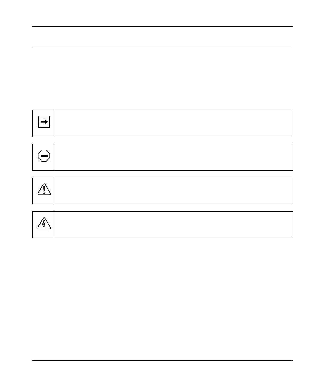
This guide use s the following formats to highlight special messages:
This format is used to highlight inf ormation of importance or special interest.
Note:
Caution:
equipment failur e or loss of data.
Warning:
equipment damage.
Danger:
mishandling equipment.
This format is used to highlight information that will help you pre vent
This format is used to highlight information about the possibili ty of injury or
This format is used to alert you that you may incur an electrical shock by
Use of Enter, Type, Press, and Click
This guide uses “enter,” “type,” “press” and “click” to describe the following actions:
• When you read “enter,” type the text and press the Enter key.
• When you read “type,” type the text, but do not press the Enter key.
• When you read “pre ss,” press only the a lphanumeric or named key.
• When you read “click,” click the left mouse button.
xvi Preface
Page 17

Reference Guide for the Model RT311 and RT314 Internet Access Gateway Routers
Other Conventions
This guide use s the following typographical conventions:
italics
courie r fon t
Initial Caps Menu titles and window and button names.
[Enter] Named keys in text are shown enclosed in square br ackets. The notation
[Ctrl]+C Two or more keys that must be pressed simultaneously are shown in text
ALL CAPS DOS file and directory names.
Book titles and UNIX file , command, and directory names.
Screen text, use r-typed command-line entries.
[Enter] is used for the Enter key and the Return key.
linked with a plus (+) sign.
Related Publications
In this document, you are directed to various RFC documents for further information. An RFC is a
Request For Comment (RFC) published by the Internet Engine ering Task Force (IETF), an open
organizat ion that defines the archite cture and operation of the Internet. The RFC documents
outline and define the standa rd protoco ls and procedures f or the Internet. The documents are listed
on the World Wide Web at
worldwide.
For more information a bout address assignment, refer to the IETF documents RFC 1597,
Allocation for Privat e Internets,
www.ietf.org
and RFC 1466,
and are mirrored and indexed at many other sites
Address
Guidelines for Manag ement of IP Addr ess Space
.
For more information a bout IP addre ss translation, refer to RFC 1631,
Translator (NAT)
Preface xvii
.
The IP Network Addre ss
Page 18

Page 19

Chapter 1
Introduction
This chapter describes the features of the NETGEAR Model RT311 and RT314 Internet Access
Gatew ay Routers and discusses planning c onsiderations for installation.
About the Router
The Model R T311 or RT314 Internet Access Gateway Router connects your local area network
(LAN) to the Internet th rough an e xter nal single -user access dev ice such as a ca ble modem or DSL
modem.
When personal computers (PCs) on the LAN need to communicate with locations on the Internet,
the PCs send requests to the router. The router translates th ose requests so that the requests appear
to originate from a single PC, rather than from a network of PCs. The router delivers the requests
to the external acc es s device for transmission to the Internet.
Features
The Model RT311 and RT314 Internet Access Gateway Routers are flexible, high-perfor mance,
easy-to-use routers. These routers provide a c ost-effective solution for connecting your entire
network to a single-user broadband line, such as a cable mode m or DSL modem. With minimum
setup, you can install and use the route r within minutes to meet the networ king requirements of
your LAN.
Introduction 1-1
Page 20

Reference Guide for the Model RT311 and RT314 Internet Access Gateway Routers
Key Features
The Model R T311 and RT314 Internet Access Gateway Routers provide the following features:
• Ethernet LAN connection at 10 megabits per se cond (Mbps) or 100 Mbps
– Internal four port 10/100 switch (Model R T314 router)
– Single 10/100 port (Model RT311 router)
– Autosensing for Ethernet (10BASE-T) or Fast Ethernet (100BASE-Tx) transmissions
– Half-duple x or full-duplex operation
• Ethernet connection to a wide area network (WAN) device, such as a cable modem or DSL
modem
– RJ-45 interfa ce al lowing connection to a 10BASE-T device
• Protocol Support
– IP routing
– Dynamic extended Networ k Address Tr anslation (NAT+) with port forwarding for
operation with a single sta tic or dynamic IP address
– Dynamic Host Configur ation Protocol (DHCP) server for dynamically assigning
network conf iguration information to PCs on the LAN
– DHCP client for dynamically obtaining configuration information from the Internet
Service Provid er (IS P)
– DNS Proxy for simplified configur ation
– PPP over Ethernet (PPPoE) support
• Login capability
– Automatically executes user login for RoadRunner cable modem service or PPP over
Ethernet accounts
• Easy installation and management
– Configure from a web browser
– Built-in Manage r interface for configuration of adv a nced features, accessible by serial
terminal or Telnet Protocol
– Configurable through the LAN—no serial connection required
• Security
1-2 Introduction
Page 21

Reference Guide for the Model RT311 and RT314 Internet Access Gateway Routers
– Network Address Translation (NAT) hides local PCs from the Internet
– Powerful packet filtering capabilities
– Incoming port forwarding for specific services
• Front panel LEDs for easy monitoring of status and activity
• Flash EPROM for firmware upgrade
• Five-year warran ty
• Free technical support se ven days a week, twenty-four hours a day
Autosensing 10/100 Ethern et
The Model R T311 and RT314 routers connect to either a 10 Mbps standard Ethernet network or a
100 Mbps Fa st Ethernet network. The local LAN interface is autosensing and is capable of
full-duplex operation.
TCP/IP
The Model RT31 1 and R T3 14 routers suppor t the Transmission Control Protocol/Interne t Protocol
(TCP/IP) and Routing Information Protocol ( RIP).
For further infor mation about TCP/IP, refer to Chapter 10, “Networks and Routing Basics.”
IP Address Masquerading by Dynamic NAT+
The Model RT311 and RT314 routers allo w se veral networked PCs to share an Internet account
using only a single IP address, which may be static ally or dynamically ass igned by your Internet
service provider (ISP). This technique, an extension of Ne twork Address Translation (NAT), is
also known as IP address masque rading and allows the use of an inexpensive single-user ISP
account.
Port Forwarding with NAT
Although NAT prevents Internet locations from directly accessing the PCs on the LAN, the route r
allows incoming traffic to b e for ward e d to sp eci fic PCs based on the serv ice port num b er o f the
incoming request.
Introduction 1-3
Page 22

Reference Guide for the Model RT311 and RT314 Internet Access Gateway Routers
Automati c Configuration of Attached PCs by DHCP
The Model RT311 and RT314 routers dynamically assign network configuration information ,
including IP, gateway, and domain name server (DNS) addresses, to atta ched PCs on the LAN
using the Dynamic Host Confi guration Protocol (DHCP). This f eatur e greatly simplifies
configuration of LAN-attached PCs.
DNS Proxy
When DHCP is enabled and no DNS addresses are specified, the ro ute r provides its own address
as a DNS server to the attached PCs. The router obtains actual DNS addresses f rom the ISP during
connection setup and forwards DNS requests from the LAN.
PPP over Ethernet (PPPoE)
PPP over Ethernet is a protocol for connecting remote hosts to the Internet over an always-on
connection by simul ating a dial-up connecti on.
Security
The Model R T311 and RT314 routers are equipped with several feature s designed to maintain
security, as described in this section.
PCs Hidden by NAT
Network address translation (NAT) opens a temporary path to the Internet for requests originating
from the loca l net work.
outside the LAN from finding and directly accessing the PCs on the LAN.
Packet Filtering
The Model RT311 and R T314 routers provide extensive packet filtering capabilities. Packets are
allowed or discarded based on their source or destination addresses, service port numbers, or ra w
data patterns within the packe t.
Port-Addres s Translation
The Model RT311 and RT314 routers perform port-address translation. Requests ori ginating from
outside the local network are allowed to reach particular local workstations based on the type of
service reque sted .
1-4 Introduction
Requests ori ginating fro m outside t he LAN
are discarded, preventing use rs
Page 23

Reference Guide for the Model RT311 and RT314 Internet Access Gateway Routers
Management
You can install, conf ig ure, and oper ate the route r within minutes af ter conne cti ng it to the networ k.
Use your browser to configure for basic Internet access, or use Telnet to access the built-in
manager interface for advanced feature s .
Browser-based Setup Wizard
A browser-based Wizard allows you to easily configu re your router for basic Internet access from
almost any type of persona l computer, such as Windows, Macintosh, or Linux.
Manager Interface
The Manag er interface manages and co n figures the router through an easily understood sc reen
process. You can access this interface thr ough the MANAGER port on the rear panel of the route r.
Connect the workstat ion you are using to configure the router to this port. You can also access the
Manager interface from across the network, using a Telnet session.
Use the Ma nag er i nte rface in any of the following situations:
• You need to make one or more computers available for access from the Internet using port
forwarding.
• You need to create additional static routes.
• You need to create filters for incomi ng or outgoing data traffic.
Introduction 1-5
Page 24

Reference Guide for the Model RT311 and RT314 Internet Access Gateway Routers
1-6 Introduction
Page 25

Chapter 2
Installing and Connecting the Router
This chapter provides instructions for installing the Model RT311 or RT314 Internet A ccess
Gateway Router.
Package Contents
The product package should contain the following item s:
• Model RT311 or RT314 Internet Access Gate wa y Router
• AC power adapter, 12 V DC output
• 10-foot twisted-pair Categor y 5 (Cat 5) Ethernet cable, straight-through wiring (white)
• 10-foot twisted-pair Categor y 5 Ethernet cable, crossove r wiring (red) (RT311 only)
•
Model RT311 and RT314 Resource
CD, including:
— This guide
— Application Notes
• Model RT311 and RT314 Internet Access Gate way Router Installation Guide
• Registration and Warranty Card
• Support Information Card
Call your dealer if there are any wrong, mi ssing, or damaged parts. Keep the carton, including
the original packing materials, to repack the router if ther e is a need to retur n it for repa ir.
Installing and Connecting the Router 2-1
Page 26

Reference Guide for the Model RT311 and RT314 Internet Access Gateway Routers
Local Network Hardware Requirements
The Model R T311 or RT314 Internet Access Gateway Router is intended for use in a network of
workstations that are interconnected by twisted-pair Ethernet or Fast Ethernet cables.
Each workstation in the network must meet the fol lowing requirements:
• An Ethernet Network Interface Card (NIC) is installed.
• Workstations are connected by a hub or switch. If all workstations on the network will not run
at the same speed (10 Mbps or 100 Mbps), a dual-speed hub or switch must be used. The
Model RT314 router provides a switch capable of either 10 Mbps or 100 Mbps operation.
• Links operating at 100 Mbps are connected with C ategory 5 cable.
• The access device to be shared (cable modem or DSL modem) has a standard 10BASE-T
Ethernet interface.
2-2 Installing and Connecting the Router
Page 27
Reference Guide for the Model RT311 and RT314 Internet Access Gateway Routers
Router Description
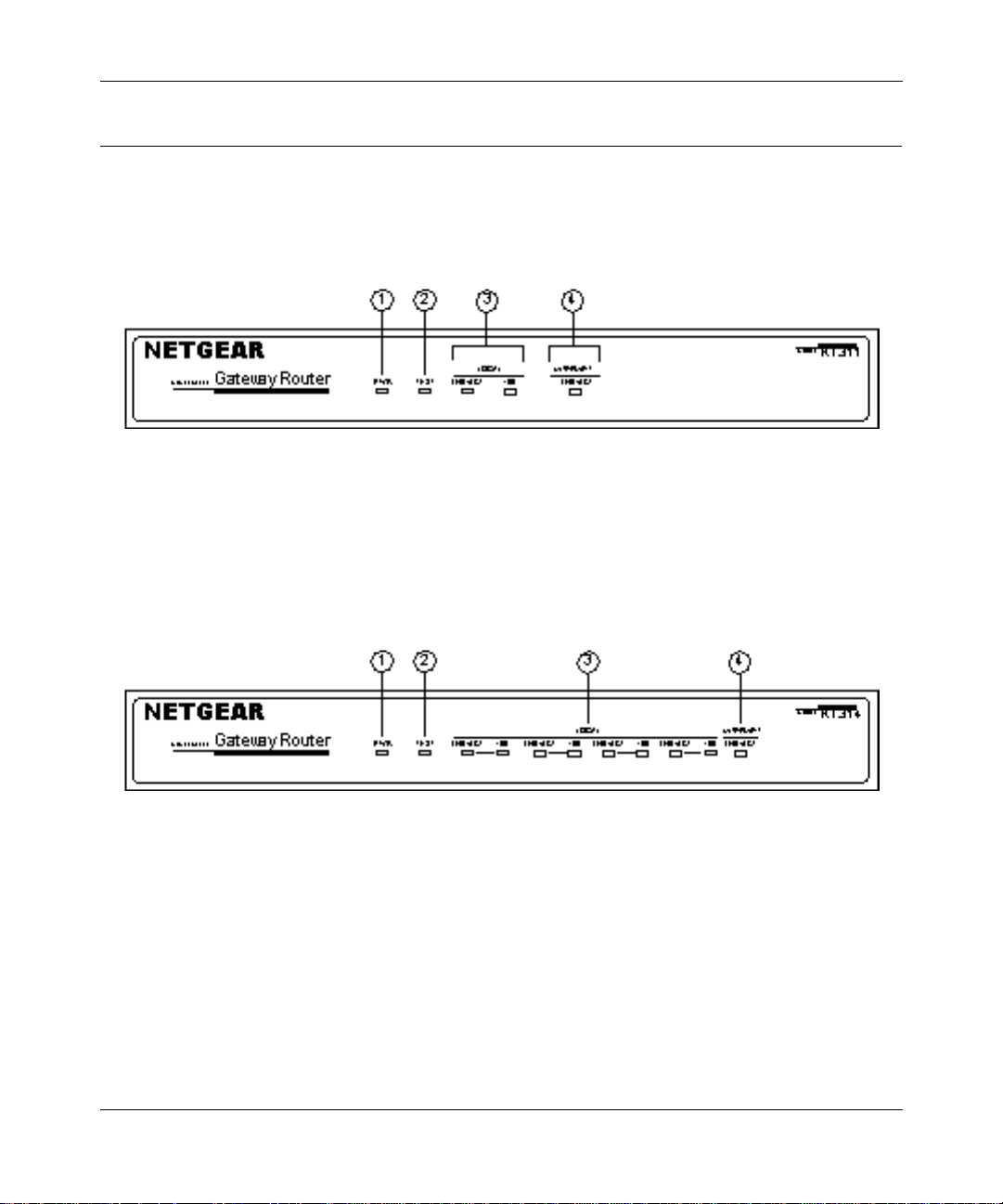
The front panels of the
Model RT311 router
contain status LEDs.
Key:
1 = PWR (Power) LED
2 = TEST LED
3 = LOCAL LAN LNK/ACT (Link/Activity) and 100M LEDs
4 = INTERNET LNK/ACT (Link/Activity) LED
Figure 2-1. RT311 Front Pane l
(Figure 2-1) and
Model RT314 router
(Figure 2-2)
Key:
1 = PWR (Power) LED
2 = TEST LED
3 = LAN LNK/ACT (Link/Activity) and 100M LEDs
4 = INTERNET LNK/ACT (Link/Activity) LED
Figure 2-2. RT 314 Front Panel
Installing and Connecting the Router 2-3
Page 28
Reference Guide for the Model RT311 and RT314 Internet Access Gateway Routers
g
g
g
g
g
g
g
g
g
You can use some of the LEDs to verify connections. Table 2-1 lists and describes each LED on
the front pa nel of the router. These LEDs are green when lit.
Tab le 2-1. LED Descriptions
Label Activity Description
PWR (Power) On
TEST On
LOCAL
LNK/ACT
(Link/Activity)
100 (100 Mbps) On
INTERNET LNK/ACT
(Link/Activity)
The rear panels of the
Off
Off
Blinkin
On
Blinkin
Off
On
Blinkin
Model RT311 router
Power is supplied to the router.
Power is not supplied to the router.
The system is not ready or has failed to start up.
The system is ready and ru nnin
The system is ini tia li z in
The LAN port has detected a link with an attached device.
Data is bein
The LAN is operatin
The LAN is operatin
The Internet port has detected a link with an attached device.
Data is bein
tranmitted or received by th e LAN port.
tranmitted or receiv ed by the Internet port.
and
Model RT314 router
.
at 100 Mbps.
at 10 Mbps.
.
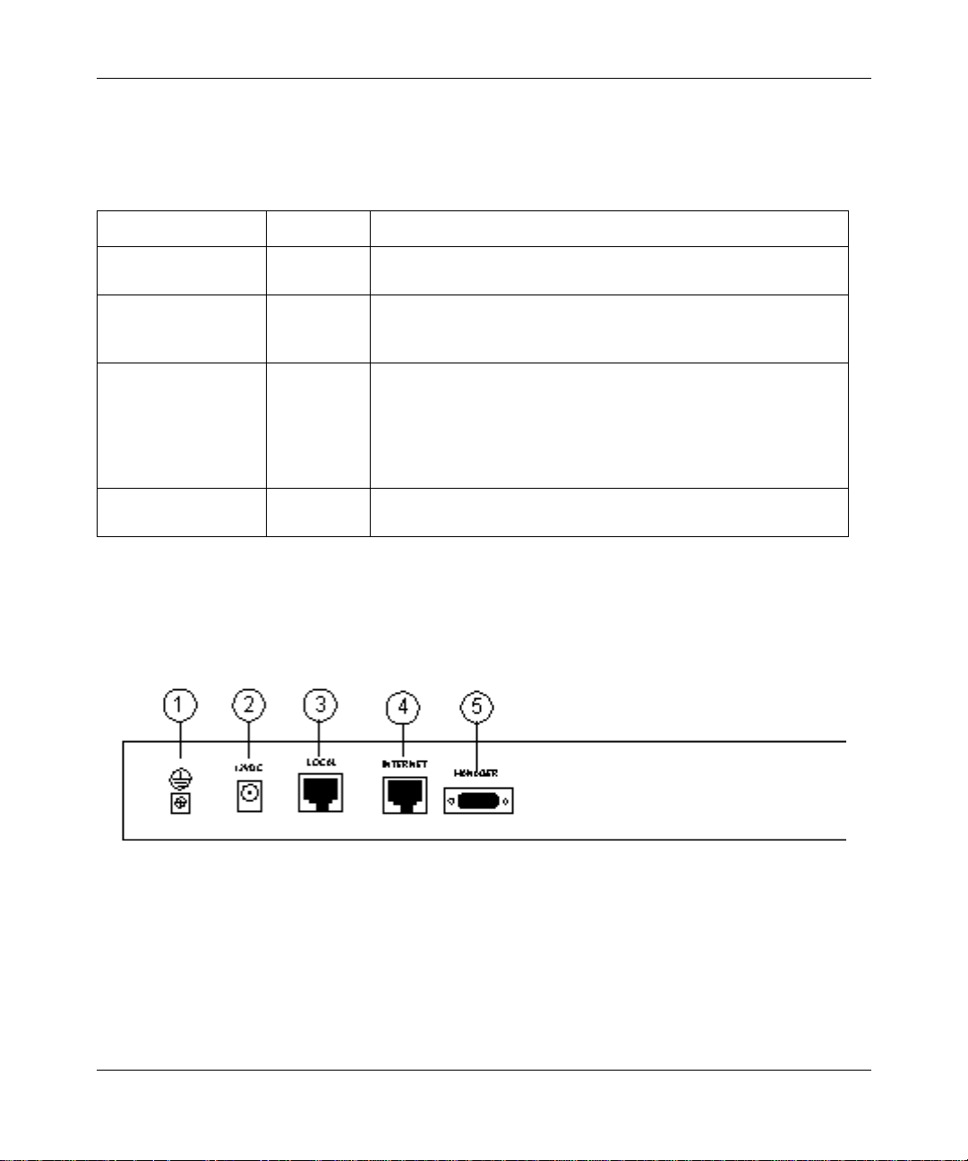
are shown in Figure 2-3 and
Figure 2-4. Refer to these diagrams to ide ntify a ll the po rts on t he r outer when you att empt t o make
any connections.
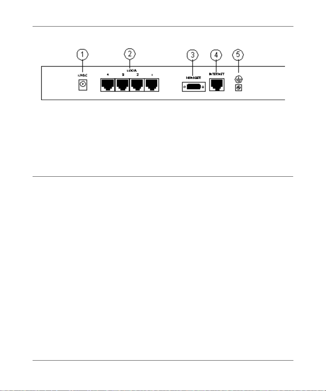
Key:
1 = Ground
2 = AC adapter outlet for connecting the AC adapter to the router
3 = Local Ethernet port for connecting the route r to th e local LAN
4 = Internet Ethernet port for connecting the router to a cable or DSL modem
5 = RS-232 Manager port f o r connecting the router to the serial port of a PC
Figure 2-3. RT 311 Rear Panel
2-4 Installing and Connecting the Router
Page 29
Reference Guide for the Model RT311 and RT314 Internet Access Gateway Routers
Key:
1 = AC adapter outlet for connecting the AC adapter to the router
2 = Local Ethernet ports for connecting the router to the local PCs
3 = RS-232 Manager port for connecti ng the router to the serial port of a PC
4 = Internet Ethernet port for connecting the router to a cable or DSL modem
5 = Ground
Figure 2-4. RT314 Rear Panel
Connecting the Router
Three connections must be made before using your router:
• Connect your local Ethernet network to the LOC AL port(s) of the router.
• Connect your cable or DSL modem to the INTER NET port of the router.
• Connect the power adapter
Connecting to your Local Ethernet Network
Your local network will attach to the router port or ports mar ked LOCAL. Because the Model
RT314 router include s a four -port switch while the Model RT311 router has a single port for
connection to your local network, the method of connection is different. Follow the proce du re
below for your specific model.
The LOCAL ports of these routers are capable of operation a t either 10 Mbps (10BASE-T) or 100
Mbps (100BASE-Tx), depending on the Ethernet interface of the attached PC, hub, or switch. For
any connection which will operate at 100 Mbps, you must use a Category 5 (CAT5) rated cable,
such as the white Ethernet cable included with the router.
Installing and Connecting the Router 2-5
Page 30

Reference Guide for the Model RT311 and RT314 Internet Access Gateway Routers
Connecting the Model RT311 router to your Local Area Net work
The Model RT311 router has a single port for connec tion to your local network. This port is wired
as a host rather than a hub, and is intended to connect to a hub or switc h in your network. To
connect the Model RT311 router to your LAN:
• Connect the LOCAL port of the router to your existing Ethernet hub or switch using the
white straight -through Ethernet cable shipped with your router.
To connect the router to a single PC:
• Connect the LOCAL port of the router to the Ethernet port of your PC using the red
Ethernet crossover cable shipped with your router.
If the Ethernet port of your PC oper ates at 100 Mbps, you must use a Category 5 r ated cable,
such as the red Ethernet cable inc luded with the Model RT311 router.
Connecting the Model RT314 rout er to your Local Area Network
The Model R T314 router incorporates a four-port switch for connection to your local network. To
connect the M odel RT314 router to your LAN:
• Connect up to four PCs directly to any of the four LOCAL ports of the router using
standard Eth ernet cables.
If your local network consis ts of more tha n four hosts, you will need to connect your router to
another hub or switch:
• Connect any LOCAL port of your Model RT314 router to the UPLINK port of an
Ethernet hub o r switch using standa rd Eth ern et ca bl e.
If the UPLINK port of your hub or switch is selectable for UPLINK or NORMAL operation,
be sure that UPLINK is selected. If the hub or switc h does not contain an UPLINK port, you
can connect to one of its normal por ts using an Ethernet crossover cable.
Connecting to the Internet
To connect the router to the Internet or WAN:
• Connect the INTERNET port of the router to your existing Internet access device, such
as a cable modem or DSL modem.
Because the INTERNET port operates only at 10 Mbps, the attached device must provide a
10BASE-T connection. No cable is provide d with your router for this connect ion. Use the
cable provided with your access device or any other standard 10BASE-T Ether ne t cable.
2-6 Installing and Connecting the Router
Page 31

Reference Guide for the Model RT311 and RT314 Internet Access Gateway Routers
Connecting the Serial Cable (Optional)
In normal operation, you will not need a seria l connection to the Manager port. This connection is
used:
• to confi gu re y our router u s ing the Manager interface if you cannot use Telnet, or
• to restore the router to factory defaults if you have lost your Manager password.
To connect the serial cable:
Plug one end of the 9-pin RS-232 cable into the MANAGER port.
1.
Plug the othe r end into a serial port (such as COM1 or COM2) of your PC.
2.
Note:
You must use a 9-pin to 25-pin adapter if your PC has only a 25-pin port
available.
Connecting the Power Adapter
To connect the router to the power adapter:
Plug the connector of the power adapter into the 12 VDC adapter outlet on the rear
1.
panel of the router.
Plug the other end of the adapter into a standard wall outlet.
2.
Verify tha t th e PW R LED on the router is lit.
3.
Verifying Power
After connecting the power adapte r to the router and a power source, the router powers on
automatically. Complete the following steps to verify that power is correctly applie d to the router:
When power is first applied, verify that the PWR LED is on.
1.
Verify tha t th e TES T LED begins to blink with in a few s econds.
2.
After approximat ely 30 seconds, verify that:
3.
The TEST LED is no t lit.
a.
The LOCAL LNK/ACT LEDs are lit for any local ports that are connected.
b.
The INTERNET LNK/ACT LED is lit.
c.
Installing and Connecting the Router 2-7
Page 32

Reference Guide for the Model RT311 and RT314 Internet Access Gateway Routers
If a LNK/ACT LED is lit, a link has been established to the connected device.
If a LOCAL port is connected to a 100 Mbps device, verify that the 100 LED is lit.
4.
You are now ready to begin configuration of your network, as descri bed in the following chapter.
2-8 Installing and Connecting the Router
Page 33

Chapter 3
Preparing Your Network
This chapter describes the preparation for connecting your PCs to the Internet using the Model
RT311 or RT314 Internet Acce ss Gateway Router. Before configuring your router, you must
perform the following tasks:
• Configure your PCs for using the TCP/IP networking protoc ol
• Order broadband Internet service from an Internet service provider (ISP)
Details of these tasks are give n in the following sections.
Preparing the PCs for IP Netw orking
The Model R T311 and RT314 Internet Access Gateway Routers use the Tr ansmission Control
Protocol (TCP) and Interne t Protoc ol (IP), commonly referred to as TCP/IP. In order to access the
Internet through the router, each PC on your network must have TCP/IP installed and selected as
the networking protocol. The required components are lis ted below for various operati ng systems:
®
• Windows
components for establishing a TCP/IP network.
• Windows 3.1: You need a TCP/IP application pa ckage such as NetManage Chameleon.
• Macintosh: You can use M acTCP, which is included with later Macintosh models.
• UNIX and variants: These operating systems usual ly include TCP/IP components.
Follow the instructi ons provided with your operating system or networking software to install
TCP/IP on your computer. Although TCP/IP is built into the Windows operating system,
beginning with Windows 95, it must be enabled and configured. Refer to “Configuring Windows
95 or Windows 98 for IP Networking” below for further instr uctions to configure your PCs for IP
networking.
Preparing Your Network 3-1
95, Windows 98, and W indows NT®: Windows 95 or later includes the software
Page 34

Reference Guide for the Model RT311 and RT314 Internet Access Gateway Routers
In your IP network, all PCs and the router must be assigned I P addresses. Each PC must also have
certain other IP configur ation inf ormation such as a subnet mask (netmask ), a domain name server
(DNS) address, and a default gateway add ress. For a detailed explanation of the meaning and
purpose of these configuration items, refer to C hapter 10, “Networks and Routing Basics.”
Unless you have a reason to do otherwise, install TCP/IP so that the PC obtains its specific
network configurat ion information from a DHCP server during bootup. The Model RT311 and
RT314 routers are shipped preconfigured as a DHCP server. The router assigns the following TCP/
IP configuration infor mation automatica lly when the PCs are rebooted:
• PC or workstation IP addresses—192.168.0.2 through 192.168.0.31
• Subnet mask—255.255.255.0
• Gateway address (the router)—192.168.0.1
• DNS server (the router)—192.168.0.1 (The router performs DNS Proxy.)
These addresses are part of the IETF-designated private address range for use in private networks.
Configuring Windows 9 5 or Windows 98 for IP Networking
All PCs must have an Ethernet network adapter card installed and must have the TCP/IP
networking protoc ol installed and configured as their networking protocol. The Windows TCP/IP
installati on must be done manually as described in this sect ion. You may be asked to insert your
Windows CD during the installation process.
To configure Microsoft
From the Windows toolbar, select Start.
1.
Select Setti ng s.
2.
Select Contro l Pa nel.
3.
Double-click on Network.
4.
®
Windows 95 or Windows 98 for IP networking:
In the displayed list of insta lled components, as illustrated in Figure 3-1, you must have an
Ethernet adapter, the TCP/IP protocol, and Client for Microsoft Networks.
Note:
It is not necessary to remove any other network components shown in the
Network window in order to install the adapt er, TCP/IP, or Client for Microsoft
Networks.
3-2 Preparing Your Network
Page 35

Reference Guide for the Model RT311 and RT314 Internet Access Gateway Routers
—
Figure 3-1. Network Dialog Box
Network Components List
If you need the ada pte r:
Click on the Add button.
a.
Select Adapter, and click on Add again.
b.
Select the manufacturer and model of your Ethernet adapter, and click on OK.
c.
If you need TCP/IP:
Click on the Add button.
a.
Select Protoc ol, and then click on Add again.
b.
Select Microso ft.
c.
Select TCP/IP, and clic k on OK.
d.
If you need Client for Microsoft Networks:
Click on the Add button.
a.
Preparing Your Network 3-3
Page 36

Reference Guide for the Model RT311 and RT314 Internet Access Gateway Routers
Select Client, and then click on Add again.
b.
Select Microso ft.
c.
Select Clien t fo r Mic roso ft Netw orks, and click on OK .
d.
You need to restart your PC after making these changes.
Configuring TCP/IP Properties
After the TCP/IP protocol components are installed, you must configure each PC with specific
information about it self and resour ces tha t are avail able on its ne twork. The simpl est way to obta in
this information is to allow the PC to obtain configuration infor mation from the internal DHCP
server of the router.
Note:
If an ISP technician config ured your PC during the installation of a broadband
modem, you may need to copy the current configurat ion information. Refer to
“Obtaining Configura tion Information After the ISP Configures Your PC” on page 3-6
for further information.
If you are using DHCP with the recommended default addresses, you can configure your PCs by
following these steps :
Install TCP/IP on each PC, selecting DHCP for obtaining con figuration settings.
1.
Physically conn ect the PCs and the router using a hub or a direct connection.
2.
Restart the router and allow it to boot.
3.
Restart each PC.
4.
The
is shipped preconfigured as a DHCP server and assig ns the following TCP/IP
router
configuration information automatically:
• PC or workstation addresses—192.168.0.2 through 192.168.0.31
• Netmask—255.255.255.0
• Gateway address (the router)—192.168.0.1
• DNS server (the router)—192.168.0.1 (The router performs DNS Proxy by default.)
3-4 Preparing Your Network
Page 37

Reference Guide for the Model RT311 and RT314 Internet Access Gateway Routers
Verifying TCP/IP Properties
After your PC has been configured and rebooted, you can check the TCP/IP configuration using
the Windows utility
button, open the Run window, type winipcfg, and click on OK. In the winipcfg display window,
select your Ethernet adapter. If you are using the default TCP/IP settings recommended by
NETGEAR, the following information will appear :
• The IP address should be between 192.168.0.2 and 192.168. 0.31.
• The subnet mask should be 255.255.255.0.
• The default gateway should be 192.168.0.1.
Click on More Info, and verify the followi ng:
• The DNS server should be 192.168.0.1.
winipcfg.exe
(for Windows NT systems, use
ipconfig.exe
). From the Start
Your Internet Account
You must contract with an Internet ser vice provider (I SP) for a single -user Inte rnet access accoun t.
You can connect your multiuser network through a single -user account by using the Network
Address Tra nslation (NA T) feature of your router. In a single-user account, your ISP assigns only
one registered Inte rnet Protocol (IP) address for your use. With most accounts, this address is
assigned dynamical ly when your PC is first boote d up while connecte d to the ISP, and you will not
need to know the actua l address. The NAT feature of your r outer tr ansla tes the pr ivate IP addresses
of your network PCs to this address for accessing the Internet.
Login Protocols
Some ISPs require a special login protocol. In this case, you will need to know what type of
protocol is used, and you will need a login name and password. The two common protocols a re:
• PPP over Ethernet (P PPoE)
• RoadRunner
Not all RoadRunner service area s requir e a login protocol. If your ISP is RoadRunner, you
should ask whether your PC must run a RoadRunner login program.
Preparing Your Network 3-5
Page 38

Reference Guide for the Model RT311 and RT314 Internet Access Gateway Routers
Account Information
Unless these items are dynamica lly a ssigned by the ISP, your ISP should give you the following
basic inform ation for your account:
• An IP address and subnet mask
• A gateway IP address, which is the address of the ISP’s router
• One or more domain name server (DNS) IP addresses
• Host name and domain suffix
If these items are supplied dynamically, your router acquires them automatically. If an ISP
technician confi gured your PC during the installation of the broadband modem, you may need to
copy this information from your PC’s Network TCP/IP Properties screen before reconfiguring
your PC for use with the router. This procedure is described in a following section.
Obtaining Configuration Information After the ISP Configures Your PC
If the ISP conf igured your W indo ws 95 or W indo ws 98 PC d uring your m odem i nstallati on, follow
the steps below to get the information you need to configure the
for Internet acces s:
router
From the Windows toolbar, select Start.
1.
Select Run ...
2.
In the Open field, type:
3.
winipcfg
Click OK.
4.
Write down the IP Address and Subnet Mask values shown in the Ethe rnet Adapter
5.
Information box.
You may need to se lect your Ethernet network adapter in order to see these values.
Click on the More Info button.
6.
Write down the ad dress es of the DNS servers show n in the Ho s t Info r m ati on box .
7.
Write down the full host name, includ ing domain suffix, shown in the Host Information
8.
box.
The host name should appear similar to this example:
3-6 Preparing Your Network
Page 39

Reference Guide for the Model RT311 and RT314 Internet Access Gateway Routers
jsmith.santaclara.gearguy.com
In this ca se, the host name pre cedes the first dot (“jsmith”), and the domain name or suffix
consists of the remaining inf or mation (“santaclara.gearguy.com”).
Write down the address of the defau lt gateway shown in the Ethernet Adapter
9.
Information box.
This information can also be obtained by selecting the Network icon in the W indows Control
Panel. Select TCP/IP and click on Properties.
Sharing the Internet Connection
The Model R T311 or RT314 Internet Access Gateway Router provides an Interne t connection for
multiple computer worksta tions through an external br oadband access device (suc h as a cable
modem or DSL modem) that is intended for use by a single workstation. For a singl e-workstation
Internet account, an Internet service provider (ISP) supplies TCP/IP configuration information for
one workstation. In order to share the Internet connection among several computers , your
must be programmed with the TCP/IP configur at ion information that would normally be used for
that single workst ation. When the route r’s INTERNET por t is connec ted to th e broadba nd modem,
the router appears to the ISP as a single PC. The router all ows the workstations on the local
network to masquer ade as the single PC to access the Internet through the broadband modem. The
method used by the router to accomplish this is called Network Address Translation (NAT) or IP
masquerading.
router
Configuration Methods
You are now ready to access and configure the router. Use one of the following options to
configure your router :
• Brows e r-b ased Wizard
You can configure your router for basic Internet access using
Internet Explore r or Netscape Navigator.
configuration Wizard, refer to Chapter 4, “Using Your Browser f or Configuring the Router .
• Man ager i n terface
The menu-based internal Manag er inte rface allows you to configur e the more advanced
features of the Mod el RT311 and RT314 routers . For ex am p le, the Man ag er interface allows
you to:
Preparing Your Network 3-7
For instructions on using the browse r-based
a web browser such as Microsoft
”
Page 40

Reference Guide for the Model RT311 and RT314 Internet Access Gateway Routers
• Make one or more computers available for access from the Internet
• Create additional static ro utes
• Create filters for incoming or outgoing data traffic
The Manager int erface is a ccessibl e through a s erial or a Telnet connection. For instr uctions on
configuring the route r using the Manager interface, r efer to Chapter 5, “Using the Manager
Interface for In itial Router Configuration.
”
3-8 Preparing Your Network
Page 41

Chapter 4
Using Your Browser for Configuring the Router
This chapter contains information about configuring your Model RT311 or RT314 Internet Acces s
Gateway Router using the router’s browser interface.
You can configure your router for basic Interne t access using
Internet Explore r or Netscape Navigator.
interface’s Setup Wizard will be suf fi cient. However, if you want to configure the advanced
features, or if the Setup W iza rd does not result in a working c onfigura tion, you will ne ed to use the
Manager in te rfac e. Re fer to Chapter 5, “Using the Manager Interface for Initial Router
Configuration,” and Chapter 6, “Using the Manager Interfac e t o Configure the Router for I nternet
Access, ” for instructions about using the Manager interface.
In most cases, configuring your router with the browser
a web browser such as Microsoft
Configuring for Internet Access
In order to use the browser-base d Setup Wizard, your PC must have a web browser program
installed such as
readily available for Windows, Macintosh, or Unix/Linux.
To configure for Internet access using your browser:
Turn on the router and wait for initialization to complete.
1.
Allow at least one minute and verify that the TEST LED is off.
Reboot your PC to obtain DHCP configuration from the router.
2.
Launch your web browser.
3.
Microsoft Internet Explo rer or Netscape Navi ga tor. Free browser programs are
In the Addre ss box of you r browser, type
4.
A login box will appear asking for a name and password. For name, type
5.
password type
Using Your Browser for Configuring the Router 4-1
1234.
Click OK.
http://192.168.0.1
and press ENTER.
admin
and for
Page 42

Reference Guide for the Model RT311 and RT314 Internet Access Gateway Routers
If your router password has been previously changed from the factory default of 1234, enter
the current password.
6. In the opening screen, shown in Figure 4-1, select WIZARD SETUP.
Figure 4-1. Browser-based configu ration mai n menu
4-2 Using Your Browser for Configuring the Router
Page 43

Reference Guide for the Model RT311 and RT314 Internet Access Gateway Routers
In the first Wizard screen , enter your account’s Host Name and Domain Name, as shown
7.
in Figure 4-2 below:
Figure 4-2. Browser-based Setup Wizard, first screen
These parameters m ay be nece ssary to a ccess your I SP’s services such as mail or news ser vers.
If you leave the Domain Name field blank, the router will attempt to learn the domain
automatically from the ISP. If this is not successful, you will need to enter it manually.
Using Your Browser for Configuring the Router 4-3
Page 44

Reference Guide for the Model RT311 and RT314 Internet Access Gateway Routers
Click on Next to go to the ISP Parameters screen, shown in Figure 4-3 below:
8.
Figure 4-3. Browser-based Setup Wizard, second screen
This screen determines whet he r a login program will be run.
If your service provider does not require a login program, leave Encapsulation as
a.
Ethernet and proc eed to Ste p 9.
If your service provider uses PPP over Ethernet (PPPoE), select Encapsulation as
b.
PPPoE, and enter these additi onal parameters:
• If your connection supports multiple ISPs, ente r the Service Name of the one you use.
Otherwise leave Service Name blank.
• Enter the user name and password provided by your ISP. These fields are case
sensitive.
• If you wish to change the login timeout, enter a new value in seconds.
Proceed to Step 9.
If your se rvice provider is RoadRunner AND you are required to run a RoadRunner
c.
login progr am, leave Encapsulation as Ethernet and sel ect Se rvice Type as either
RR-Manager or RR-Toshiba. Enter these additional parameters: .
• If your cable modem is Toshiba, select RR-Toshiba. Otherwise select RR-Manager.
• Enter the user name and password provided by your ISP. These fields are case
sensitive.
4-4 Using Your Browser for Configuring the Router
Page 45

Reference Guide for the Model RT311 and RT314 Internet Access Gateway Routers
• If RoadRunner provided an authent ic ation server addr ess, enter it as Login Server IP
address. Otherwise, le ave this field as 0.0.0.0.
Not all RoadRunner regi ons require a login program. If your re gion does not require a
login, leave Service Type as Standard.
9. Click on Next to go to the final Wizard screen shown in Figure 4-4 below .
Figure 4-4. Browser-based Setup Wizard, third screen
This screen provides setup f or the fo llowing parameters:
WAN IP Addre ss Assignment: Unless your ISP has assigned a fixed pe rmanent IP
a.
address for y our use, select "Get automaticall y from ISP". Otherwise, ente r your IP
Address, Su bnet Mask, and the IP Add ress of your ISP’s gateway router.
DNS Server Address Assignment: If you kn ow that your IS P does not automatically
b.
transmit DNS addresses to the router during login, select “Use this serve r” and enter
the IP address of the ISP’s DNS server .
A DNS server is a host on the Internet that translates Internet names (such as www
addresses) to numer ic IP addresse s. Typically your I SP transfers the IP addresses of one or
two DNS servers to your route r during login. If the ISP does not transfer an address, you
must obtain it from the ISP and enter it manually here. If you enter an address here, you
should reboot your PCs after configuring the router.
Using Your Browser for Configuring the Router 4-5
Page 46

Reference Guide for the Model RT311 and RT314 Internet Access Gateway Routers
WAN MAC address: If your ISP allows access by only one specific PC’s Ethernet
c.
MAC address, select "Spoof this PC’s MAC address" and enter the IP address of that
PC.
• For convenience, the IP add ress of the PC you are now us ing s hould already appear. If
this is not the PC whose MAC address is to be used, enter that PC's IP address .
• Some ISPs will register the Ethernet MAC address of the network interface card in
your PC when your account is fir st opened. The y will the n only accept tr af fic from the
MAC address of that P C. This feature allows your router to masquerade as that PC by
using its MAC address.
10. Click on Finish.
Click on the NETGEAR website address to test your Internet connection.
11.
If the NETGEAR website does not appear within one minute, r efe r to Chapter 9,
“Troubleshooting”.
4-6 Using Your Browser for Configuring the Router
Page 47

Reference Guide for the Model RT311 and RT314 Internet Access Gateway Routers
g
Other Features of the Browser Interface
In addition to the Setup Wiza rd, the browser inte rface provides a limited amount of status and
usage information. From the Main Menu of the browser interface, click on Maintenance to view
the System Status screen, shown in Figure 4-5.
Figure 4-5. Browser-based configuration, System Status screen
This screen shows the following parameters:
Tab le 4-1. Menu 3.2 - System Status Fields
Field Description
System Name This field displ ays the Host Name assi
Router Firmware Version This field displ ays the router fir mware version.
WAN Port These parameters apply to t he Int ernet (WAN) port of the router.
Using Your Browser for Configuring the Router 4-7
ned to the router.
Page 48

Reference Guide for the Model RT311 and RT314 Internet Access Gateway Routers
g
g
g
g
g
g
g
Tab le 4-1. Menu 3.2 - System Status Fields
Field Description
IP Address This field displays the IP address being used by the Internet (WAN) port
of the router. If no address is shown, the router cannot connect to the
Intern et.
IP Subnet Mask This field displays the IP Subnet Mask bein
port of the router.
DHCP If set to None, the router is confi
WAN.
If set to Client, the rout er is confi
dynamically fr om the ISP.
LAN Port These parameters appl y to the Local (WAN) port of the router.
IP Address This field displ ays the IP address bein
the router. The default is 192.168.0.1
IP Subnet Mask This field displ ays the IP Subnet Mask bei n
port of the router. The default is 255.255. 255.0
DHCP If set to None , the router will not assi
LAN.
If set to Server, the router is confi
PCs on the LAN.
ured to use a fixed IP address on the
ured to obtain an IP address
ured to assign IP addr esses to local
used by the Internet (WAN)
used by the Local (LAN) port of
used by the Local (LAN)
n IP addresses to loca l PCs on the
Click on the “Show Statistics ” butt on to display router usage stat istics, as shown in Figure 4-6
below:
Figure 4-6. Browser-based configuration, Router Statistics screen
4-8 Using Your Browser for Configuring the Router
Page 49

Reference Guide for the Model RT311 and RT314 Internet Access Gateway Routers
g
g
This screen shows the following statistics:.
Tab le 4-2. Router Statistics Fields
Field Description
Port The statistics for the W AN (Internet) and LAN (local) ports. For each port, the screen
displays:
Status The link status of the port.
TxPkts The number of packets tr ansmitted on thi s port since reset or manual clear.
RxPkts The number of packets received on this port since reset or manual clear.
Collisions The number of collisions on this port since reset or manual clear.
Tx B/s The curre nt lin e ut iliz a ti o n—percent a
Tx B/s The avera
Up Time The tim e elapsed since this port acquired link.
System up Time The time elapsed since the last power cycle or reset.
Poll Interval Specifies the intervals at which the statistics are updated in thi s window. Click on Stop
to freeze the display.
e line utilization —average CLU for thi s port.
e of current bandwidth used on this port.
Using Your Browser for Configuring the Router 4-9
Page 50

Reference Guide for the Model RT311 and RT314 Internet Access Gateway Routers
4-10 Using Your Browser for Configuring the Router
Page 51

Chapter 5
Using the Manager Interface for Initial Router
Configuration
This chapter contains information about basic conf iguration for your Model RT311 or RT314
Internet Acce ss Gateway Router using the internal Manager interface. The initial configuration
consists of:
– accessing the Manager,
– naming the router,
– and setting up the LAN interface, including DHCP parameters to be assigned to the
attached PC s.
After you have p erformed basic router configuration, proceed to Chapter 6, “Using the Manager
Interface to Con figure the Router for Internet Access,” and Chapter 7, “Configuring Filters,” to
configure Inte rnet access and additional features.
You can also use the browser-based setup to configure basic ro uter features, and
Note:
later use the Manager interface to configure advanced fea tures.
Connecting for Configuration
The Manager interface is accessible by a serial connection thr ough the MANAGER port on the
rear panel of your router or by a Telnet connection over the local network, as described in the
following sections.
Using the Manager Interface for Initial Router Configuration 5-1
Page 52

Reference Guide for the Model RT311 and RT314 Internet Access Gateway Routers
Connecting Through a Serial Port
You can access the internal Manager interface through a serial port by using a VT100 terminal or
by using a terminal-emulation program on your PC or workstation. If you are using Windows, for
example, Microsoft® provides HyperTerminal with Windows 95 and Windows 98. Be sure to set
the program for VT100 emulation, including arrow keys.
Serial port parameter s are as follows:
• 9600 bps
• 8 data bits
• 1 stop bit
• No parity
• No flow control
When the serial connection has been established, press any key. The router should respond with a
“Password:” prompt. Type the current password to access the Manager interface. The default
password is 1234.
Connecting Through a Telnet Connection
You can access the built-in interface by a Telnet call from any TCP/IP workstation on the LAN or
the remote network. In order to use the Telnet Protocol, you must know the current IP address of
the router. If you do not know the router’s current IP address, you m ust use a serial c onnection to
assign an IP address. The router is shi ppped with a default address of 192.168.0.1.
To establish a Telnet connection from the LAN, you must set up your workstation to reach the IP
address of the router by doing one of the following:
• Set your workstation to an IP address on the currently programmed subnet of the router.
• Add a route to the static routing table of the workstation to indicate that the rout er can be
reached through the local LAN port.
T o access the router by Telnet from a Windows PC:
From the Windows toolbar, select Start.
1.
Select Run ...
2.
In the Open field, type:
3.
telnet 192.168.0.1
5-2 Using the Manager Interface for Initial Router Configuration
Page 53

Reference Guide for the Model RT311 and RT314 Internet Access Gateway Routers
Click on OK.
4.
The router s hould respon d with a “Pa ssword:” prompt. Type the cu r rent pa ss word to ac cess the
Manager in te rfac e. Th e de fault password is 1234.
.When using Telnet, consider the following restrictions:
• Single administrator
To p rev e nt co nfu s ion an d discrep a n cy on the con figuration, the router allows only one
terminal connection a t any time. The router also gives priority to the RS-232 connection over
T elnet. If you have already connected to the router through Telnet, you are logged out if
another user then connects thr ough the RS-232 cable. You can use a Te lnet connection only
after the other administr ator has disconnecte d.
• System timeout
When you are connected to the router through Telnet, there is a system timeout of 5 minutes
(300 seconds). If you are not config uring the device and leave it inact ive for this timeout
period, the router automatically disconnects from the Telnet session.
Using the Manager Interface for Initial Router Configuration 5-3
Page 54

Reference Guide for the Model RT311 and RT314 Internet Access Gateway Routers
Using the Manager Interface
Turning on Power to the Router
When power is first applied to the router, several internal tests are performed by the router.
Your Internet line is initia lized at this time. During the initialization, the sta rt-up display is
transmitted over the serial Manager port, as illustrated in Figure 5-1. Note that this display is only
visible from a serial c onnec tion, a s the router will not accept a Telnet connection unt il i nitial izati on
is comple te.
Bootbase Version: V1.12 | 1/27/2000 18:31:01
RAM: Siz e = 4096 Kbyte s
DRAM POST: Testing: 4096K OK
FLASH: intel 8M
RAS Version: V3.20(M.00) | 5/26/2000 19:43:28
Press any key to enter debug mode within 3 seconds.
..........................................
Figure 5-1. Start-up Di s pl ay
5-4 Using the Manager Interface for Initial Router Configuration
Page 55

Reference Guide for the Model RT311 and RT314 Internet Access Gateway Routers
To log in to the Manage r interface:
Press [Enter] when prompted.
1.
A login screen is displayed and prompts you to enter a password.
Enter the default password 1234 to reach the Main Menu (Figure 5-2) of the Manager.
2.
RT311 Main Menu
Getting Started Advanced Management
1. General Setup 21. Filter Set Configuration
2. WAN Setup
3. LAN Setup 23. System Password
4. Internet Access Setup 24. System Maintenance
Advanced Applications
11. Remote Node Setup
12. Static Routing Setup
15. SUA Server Setup
99. Exit
Figure 5-2. Manager Ma i n M e nu
After you have accessed the Manager, the router automatica lly logs you out and displays a
blank screen if there is no activity for longer than 5 minutes. If you see a blank screen while
connected by serial por t, pr ess [Enter] to displ ay the password screen again. If you are logged
out of a T elnet session, you must open a new Telnet session.
Using the Manager Interface for Initial Router Configuration 5-5
Page 56

Reference Guide for the Model RT311 and RT314 Internet Access Gateway Routers
g
g
g
g
g
g
g
g
g
g
Navigating the Manager
The Manager is th e interfa ce that you use to confi gure your router. Table 5-1 lists and describes the
commands that enable you to navigate through the Manager menus.
Tab le 5-1. Manager Menu Commands
Action Description
Move forward to
another menu
Move back to a
previous menu
Move the cursor Press [Enter]. You can also use the Up and Down keys to move to t he previous and
Enter information There are two types of fiel ds for enterin
Required fields Some of the fields in the Mana
N/A fields Some of the fields in the Mana
Save your
confi
uration
Enter the number of the submenu and press [Enter].
Press [Esc]. The only exception is the Main Menu, where typin
method to exit from the Mana
next fields, respectively.
to enter the appropriate information. The second
When choosin
required fields initially show a question mark (?), indicati n
be filled in before that menu can be saved.
Press [Enter] when prompted to press ENTER to confirm or ESC to cancel. In most
cases, saving the data on the screen takes you to the previous menu.
options, pres s the space bar to toggle through the available options.
er.
selected parameters. The first requires you
ives you options to choose from.
er are essential in or der to configure the router. The
er show N/A, meaning the option is not avai lable.
99 is the only
that the informati on m ust
Manager Menu Summary
Table 5-2 describes the top-level Manager menus.
Tab le 5-2. Manager Menu Summar y
Number Menu Title Description
1 General Setup Specify a router name.
2 WAN Setup Set full/half duplex to the external wide area network (WAN)
connection. Thi s connection is typically a broadband modem
connected to the Internet port of the router. Also allows selection of
the MAC address.
3 LAN Setup Confi
ure the loc al area network (LAN) parameters, including IP
address and DHCP operation .
5-6 Using the Manager Interface for Initial Router Configuration
Page 57

Reference Guide for the Model RT311 and RT314 Internet Access Gateway Routers
g
g
g
g
g
g
g
Table 5-2. Ma nager Menu Summary (continued)
Number Menu Title Description
4 Internet Acces s Setup Set up a basic Inte rnet connection.
11 Remote Node Setup Confi
12 Static Routin
15 SUA Server Setup Confi
21 Filter Set Confi
23 System Password Chan
24 System Maintenance Provi de system status, dia
99
Exit Exit from the Mana
Setup Manually configure static routes. The router supports eight static
uration Set up filters to be used in Menu 3 and Menu 4 to provide security
ure additi onal parameters of the Internet connection
routes.
ure forwardi ng of specific incom ing service request s to local
hosts.
and traffi c control.
e password for Manager access.
nostics, and firmware upload.
er.
Using the Manager Interface for Initial Router Configuration 5-7
Page 58

Reference Guide for the Model RT311 and RT314 Internet Access Gateway Routers
General Setup Menu
The General Setup Menu contains administrative and system-r elated informati on, suc h as the
router name .
T o enter administrative and system-related information:
Enter 1 from the Mai n M en u to display Menu 1 - General Setup, as illustrated in
1.
Figure 5-3.
Menu 1 - General Setup
System Name = MyRT311
Domain Name: santaclara.gearguy.com
Configure Dynamic DNS= No
Press ENTER to Confirm or ESC to cancel:
Figure 5-3. Menu 1 - General Setup
In the System Name field, enter a name for identifying the router.
2.
For identificat ion purposes, choose a descriptive name for the router, such as MyRT311. If
your ISP has assigned a host name for your PC, the System Name in some cases must be set to
the host nam e. The System Name can inc lude up to 30 alphanumeric characters. Spaces are
not allowed , but da she s ( - ) and unders co res ( _ ) are acc ep tab l e.
(Optional) In the Domain Name field, enter the domain name of your Internet service.
3.
The Domain Name may be helpful in accessing some of the services of your ISP, such as
email, news servers and customer support. If your account’s full server names look like this:
mail.xxx.yyy.com
your domain name is xxx.yyy.com.
(Optional ) Co nfi gure fo r D ynamic DNS.
4.
If you wish to use Dynamic DNS, refer to “Dynamic DNS“ on page 6-10.
5-8 Using the Manager Interface for Initial Router Configuration
Page 59

Reference Guide for the Model RT311 and RT314 Internet Access Gateway Routers
g
g
WAN Setup
Menu 2 enables you to c onfigure the 10 M bps Etherne t port t o a broadba nd modem devic e, such as
a cable or DSL modem. This port is labeled INTERNET on the rear panel of the router.
Figure 5-4 shows Menu 2 - WAN Setup.
Menu 2 - WAN Setup
MAC Addr ess:
Assigned By= Factory default
IP Addr ess= N/A
Press ENTER to Confirm or ESC to cancel:
Figure 5-4. Menu 2 - WAN Setup
Table 5-3 lists and describes the fields for Menu 2 - WAN Setup.
Ta b le 5 -3 . WAN Setup Fiel ds
Field Description
MAC Address The MAC Address is the 48-bit Ethern et addr ess of the router’s INTERNET port .
Assi
ned By Set to Factory default to use the router’s internal globally unique MAC address.
Set to ‘IP address att ached on LAN’ to acquire and substitute the MAC address of
one of your PCs on the local network. Some ISPs will only accept traffic from the
MAC address of one PC. This feature allows your router to masquerade as that PC
by usin
IP Address If you selected IP address attached on LAN in the previo us field, you must specify
the IP address of the local PC with the MAC address to be use d by the router.
Using the Manager Interface for Initial Router Configuration 5-9
its MAC address.
Page 60

Reference Guide for the Model RT311 and RT314 Internet Access Gateway Routers
LAN Setup
Menu 3 enables you to configure the Ethernet LAN paramete rs, including fil te rs, DHCP, and IP
address information. These parameters specify the behavior of the route r’s local port.
From the Main Menu, enter 3 to display M en u 3 - LAN Set up (Fig ure 5-5 ).
1.
Menu 3 - LAN Setup
1. LAN Port Filter Setup
2. TCP/IP and DHCP Setup
Enter Me nu Selectio n Nu mber:
Figure 5-5. Menu 3 - LAN Setup
Select one of the following submenus:
2.
• Menu 3.1 LAN Port Filter Setup
• Menu 3.2 TCP/IP and DHC P Setup
Refer to the following sections for descr iptions of these submenus. Refer to Table 5-1 on page
5-6 for information about navigating through the menus.
LAN Port Filter Setup Menu
The LAN Port Filter Setup Menu allows you to apply filter sets to control your Ethernet traffic.
Filters are used to block certain packets, to reduce traffic, and to prevent security breaches. You
must first create these fil ter sets using Menu 21, and then apply them by number in this menu.
Refer to Chapter 7, “Configuring Filters,” for more information about configuring and applying
filters.
5-10 Using the Manager Interface for Initial Router Configuration
Page 61

Reference Guide for the Model RT311 and RT314 Internet Access Gateway Routers
g
g
g
Table 5-4 lists and describes the interface and filter choices in the LAN Port Filter Setup menu.
Ta b le 5 -4 . Menu 3.1 - LA N Por t Fil te r Set up Fields
Field Description
Input and Output Filter Sets Enter filter sets by number to filter packets comin
or
oing out to the LAN (Output).
Protocol Filter s Enter the numbers of one or more IP filter sets created in Menu 21.
Device Filters Enter the numbers of one or more
eneric filter sets created in Menu 21.
from the LAN (Input)
TCP/IP and DHCP Setup
The
Model RT311 and RT314 routers
have the capa bility to act as a DHCP server, allowing them
to assign IP, DNS, and default gateway addresses to attached PCs or workstations. The assigne d
default gateway address is the LAN address of the router, as set in the TCP/IP section. Each pool
address is tested befor e it is assigned to avoid duplicate addresses on the LAN.
If you are setting up your network for the first time, read about IP addresses starting with “IP
Addresses and the Internet” on page 10-2 and “IP Configuration by DHCP” on page 10-10 for an
explanation of DHCP and information a bout how to assi gn IP addresses for your network.
For most applications, the default DHC P and TCP/IP settings of the router are satisfa ctory. The se
default settings are:
• LAN IP address 192.168.0.1 with subnet mask 255.255.255.0.
• DHCP server enabled with 32 client addresses sta rt ing from 192.168.0.1.
• DNS Proxy enabled ( the router address is assigned as a DNS server).
Using the Manager Interface for Initial Router Configuration 5-11
Page 62

Reference Guide for the Model RT311 and RT314 Internet Access Gateway Routers
g
g
g
g
g
g
g
g
Table 5-5 lists and describes the fields to use for setting up TCP /IP and DHCP parameters in
Menu 3.2. When you finish enter ing information in all of the fields, press [Enter] at the prompt
Press ENTER to Confirm. Your selections are saved. Press [ Esc] at any time to cancel the entries
you have made.
Note:
If you change the LAN IP address of the router while connected through Telnet,
you lose the Telnet session. You must then open a new Telnet connection to the new IP
address and log in again.
.
Table 5-5. Menu 3.2 - TCP/IP and DHCP Setup Fields
Field Description
DHCP: If set to Server , the router acts as a DHCP server.
If set to None, the router’s DHCP server is dis abled.
DHCP Confi
Client IP Pool Startin
Address
Size of Client IP Pool Thi s fi eld is the number of sequential addresses available for
Primary DNS Server If you want the router to provide the Primary DNS Server address to
Secondary DNS Server If you want the router to assi
TCP/IP Setup:
IP Address Enter the IP address of the LAN interface of the router in dotted-decim al
IP Subnet Mask An IP address consists of two parts, the networ k ID and the host ID. The
uration:
This field is the beginning of the range of addresses to assign.
nment to attached hosts. The maximum is 32.
assi
attached hosts, enter the DNS addres s in this field. If this field is 0.0. 0.0,
the router ass i
Proxy if it can obtain a DNS address fr om the ISP.
to attached hosts, enter the address in this field.
notation (four 8-bit numbers, bet ween 0 and 255, separated by periods,
for example, 192.168.0.1). Every devi ce on the TCP/IP network must
have a unique IP address.
IP Subnet Mask specifies the network ID portion of the address, written
in dotted-de cimal n otati on. The router aut omatic ally calcul ates t his m ask
for the class of the IP address that you assi
special need for subnettin
the router. All hosts on the LAN se
ns its own address as DNS Server, and perfor ms a DNS
n the Secondary DNS Server address
n. Unless you have a
, use the default subnet mask calculated by
ment should use the same mask.
5-12 Using the Manager Interface for Initial Router Configuration
Page 63

Reference Guide for the Model RT311 and RT314 Internet Access Gateway Routers
g
g
g
g
g
g
g
g
g
g
g
g
Table 5-5. Menu 3. 2 - TCP/IP and D HC P Setu p Fields (cont i nued)
Field Description
RIP Direction This parameter determines how the router handles RIP (Routing
Information Protocol). RIP allows the router to exchan
information with other routers. I f set to None (default), the router does
not partic ipate in any RIP exchan
router broadcas ts the routin
incorporates RIP broadcasts by other routers into its routin
to In Only, the router broadcasts its routin
Out Only, the router broadcasts its routin
broadcast packets that it receives. Usually, you shoul d leave this
parameter at the default (None)
RIP Version This field determines the format and broadcasting method of any RIP
(Routin
RIP options are supported by the Model RT311 router:
• RIP-1—The router sends RIP-1 messa
• RIP-2B—The router sends RIP-2 messa
• RIP-2M—The router sends RI P-2 messa
For most applications, the recommended version is RIP-1.
Multicast Som e streamin
support IP Multicast. To enabl e Multicast routin
or IGMP-v2.
Information Protoc ol) transmi ssions by the router . The following
media applications (e.g. Cisco IP/TV, RealPlayer) now
e with other routers. If set to Both, the
table of the router on the LAN and
table on the LAN. If set to
table, but it ignores any RIP
.
es only.
es in broadcast format.
es in multicast format.
e routing
table. If set
, select either IGMP-v 1
Manager Password Setup
For security, you should change the Manager password from the default value of 1234.
T o change the Manager password:
Select option 23, System Password, from the main menu.
1.
Menu 23 - System Password opens (Figure 5-6).
Using the Manager Interface for Initial Router Configuration 5-13
Page 64

Reference Guide for the Model RT311 and RT314 Internet Access Gateway Routers
Menu 23 - System Password
Old Pass word= ?
New Pass word= ?
Retype to confirm= ?
Enter here to CONFIRM or ESC to CANCEL:
Figure 5-6. Menu 23 - System Password
Enter your previous syst em password, and press [Enter].
2.
Enter your new system password, and press [Enter].
3.
Enter your new system password again for confirmation, and press [Enter].
4.
You must enter this new password whe n you want to access the Manager through the serial port or
by a Te lnet connection.
If you lose or forget the Manager password, you must clear the conf iguration of the router as
described in Chapter 9, “Troubleshooting. ” Clearing the configuration causes the Manager
password to revert to the defau lt, 1234.
5-14 Using the Manager Interface for Initial Router Configuration
Page 65

Chapter 6
Using the Manager Interface to Configure the
Router for Internet Access
This chapter describes how to configure your Model RT311 and RT314 Internet Access Gateway
Routers for Internet acc ess using the internal Manage r interface. For information about using the
Manager in te rfac e, ref er to Chapter 5, “Using the Manager Interface for Initial Router
Configuration.”
Internet Acces s Confi g uration
You can configure the router for basic access to your Int ernet service provide r (ISP) using
Manager Menu 4, Internet Access Setup. The configu rati on information r equir ed is eithe r suppli ed
directly by your ISP or must be obtained from your preconfigured PC as described in “Obtaining
Configuration Inf ormation After the ISP Configures Your PC” on page 3-6. Additional
configuration parameters are availabl e in Menu 1 1, Remote Node Setup.
To co n fig u re yo ur router fo r In tern et acce s s:
Enter 4 from the Mai n M en u to display Menu 4 - Inter ne t Ac ces s Setu p.
1.
Menu 4 - Internet Access Setup opens (F igure 6-1).
Using the Manager Interface to Configure the Router for Internet Access 6-1
Page 66

Reference Guide for the Model RT311 and RT314 Internet Access Gateway Routers
Menu 4 - Internet Access Setup
ISP's Name= ChangeMe
Encapsu lation= Et he rnet
Serv ice Type= Standa rd
My Login= N/A
My Password= N/A
Login Server IP= N/A
IP Address Assignment= Dynamic
IP Address= N/A
IP Subnet Mask= N/A
Gateway IP Address= N/A
Single User Account= Yes
Press ENTER to Confirm or ESC to Cancel:
Figure 6-1. Menu 4 - Internet Access Setup
Enter the name of your ISP in the ISP’s Name field (for example, myISP).
2.
This information is requi red f or identification purposes only.
If your ISP uses PPP over Ethernet (PPPoE), use the space bar to toggle Encapsulati on
3.
to PPPoE. Otherwise, leave it as Ethernet .
PPP over Ethernet (PPPoE) is a type of connection that requires the use of a dialer progra m
such as Microsoft Dial-Up Networking to access your DSL or cable modem. In this case, the
router will perform this function, and it will not be necessa ry to run the diale r on your attac hed
PCs.
If your connection suppor ts multiple ISPs, ent er the Service Name of the one you use.
a.
Otherwise, leave Service Name blank.
Enter your account’s login name as My Login.
b.
Enter your account’s password as My Password.
c.
If you selected Ethernet Encapsulation, use the space bar to toggle the Se rvi ce Type field
4.
to either RoadRunner or Standard.
This field determines whet her the RoadRunner login progra m will be run. If your ser vice
provider is not RoadRunner or if your RoadRu nner region does not require the login program:
6-2 Using the Manager Interface to Configure the Router for Internet Access
Page 67

Reference Guide for the Model RT311 and RT314 Internet Access Gateway Routers
Select Stan da rd .
a.
If your Service Type is RoadRunner and your RoadRunner region requires the login program:
Select the RoadRunner login program used in your region.
a.
Enter the login name and password provided by RoadRunner.
b.
If RoadRunner provided an authentic ation server addr ess, enter it as Login Server
c.
IP address. Otherwise, leave this field as 0.0.0. 0.
Use the space bar to toggle the IP Address Assignment field to Static or Dynamic.
5.
If your servic e provider has assigned you an IP address to be manually configured in your PC,
select Static. In this case, ente r your assigned IP address, subnet mask, and gateway address
(the address of the ISP’s router). If you do not know the gateway address, leave this field as
0.0.0.0.
Use the space bar to toggle the Single User Accou nt field to Yes.
6.
Press [Enter] at the Press ENTER to Confirm... prompt to confirm your selections.
7.
You can press [Esc] at any time to cancel your selections. When you save this menu, the ro uter
automatically cre at es a default static route to the ISP.
Configuration for Local Servers
Although NAT causes your entire local network to appear as a single machine to the Internet, you
can make loca l servers for different services (for example, FTP or HTTP) visible and available to
the Internet. Requested services are ident if ied by port numbers in an incoming IP packet. For
example, a packet t hat is sen t to the externa l IP a ddress of your r outer and desti ned fo r port number
80 is an HTTP (Web server) request, and port 21 is an FTP request. Examples of port numbe rs are
shown at the bottom of Menu 15, although you are not limited to thes e choic es. See IETF
RFC1700, “Assigned Numbers,” for port numbers for common protocols..
Note:
Many residential broa dban d ISP accounts do not allow you to run any server
processes (such as a Web or FTP server) from your location. Y our ISP may periodically
check for servers and may suspend your account if it discovers any active services at
your location. If you are unsure, refer to the Accep tab l e Use Poli cy of your ISP.
Using the Manager Interface to Configure the Router for Internet Access 6-3
Page 68

Reference Guide for the Model RT311 and RT314 Internet Access Gateway Routers
Use Menu 15, SUA Server Setup, to configure the router to forward incoming protocols to I P
addresses on your local network based on the port number. In addition to servers for specific
protocols, you can also specify a default server to which all other incoming protocols are
forwarded.
Menu 15 - SUA Server Setup is shown in Figure 6-2.
Menu 15 - Multiple Server Configuration
Port # IP Address
------ ---------------
1.Default 0.0.0.0
2. 0 0.0.0.0
3. 0 0.0.0.0
4. 0 0.0.0.0
5. 0 0.0.0.0
6. 0 0.0.0.0
7. 0 0.0.0.0
8. 0 0.0.0.0
Press ENTER to Confirm or ESC to Cancel:
Figure 6-2. Menu 15 - SUA Server Setup
Local Web and FTP Server Example
If a loca l PC, with a private address of 192.168.0.3, acts as a Web and FTP server, c onfigure
Menu 15 to f orward ports 80 (HTTP) a nd 21 (FTP) to local address 192.168.0.3 as shown in
Table 6-1.
Tab le 6-1. Menu 15 Field Entries (Example)
Port # IP Address
Default 0.0.0.0
80 (HTTP) 192.168.0.3
21 (F TP) 192.168.0.3
6-4 Using the Manager Interface to Configure the Router for Internet Access
Page 69

Reference Guide for the Model RT311 and RT314 Internet Access Gateway Routers
In order for a remote user to access this server from the Internet, the remote user must know the IP
address that has be en assigned by your ISP. If this address is 172.16.1.23, for example, an Internet
user can access your Web server by directing the browser to http://172.16.1.23. The assigned IP
address can be found in Menu 24.1, in the WAN IP Address field.
Sample considerations for this application are:
• If your account’s IP address is assigned dynamically by your ISP, the IP address may change
periodically as the DHCP lease expir es.
• If the IP addre ss of the local PC is assigne d by DHCP , it may change when the PC is rebooted.
T o avoid this, change the configuration of your PCs to use fixed private addresses rather than
DHCP-assigned address es.
• Local PCs must access the local server using the PCs’ local LAN address (192.168.0.3 in this
example). Attempts by local PCs to acces s the server using the external I P address
(172.16.1.23 in this example) will fail.
Local Game Host or Vide oconference Example
Some online games and videoconfere nci ng applications are incompatible with NAT . The Model
Model RT311 and RT314 routers are programmed to rec ognize some of these applications and to
work properly with them, but there are other applications that may not function well. In some
cases, one local PC can run th e applica tion proper ly if that PC’s IP address is entered as the default
in Menu 15. If one local PC acts as a game or videoconference host, ent er its IP address as the
default.
Setting Static Routes
Under normal circumstances, the router has adequate rout ing information after you configure the
Internet acc ess information, and you do not need to configure additional static routes. You must
configure static routes only for unusual cases such as multiple routers or multiple IP subnets
located on your network.
T o view the routes in the routing ta ble:
In the Manager interface, ope n M en u 24 - Sy stem M ai nte na nc e.
1.
T ype 8 and press [Enter] to change to the Command Interpreter Mode.
2.
At the command prompt, type:
3.
ip route stat
Using the Manager Interface to Configure the Router for Internet Access 6-5
Page 70

Reference Guide for the Model RT311 and RT314 Internet Access Gateway Routers
Press [Enter].
4.
The command interpreter displa ys the static IP routing table as shown in the example in
Figure 6-3.
ras> ip rout stat
Dest FF Len Interface Gateway Metric stat Timer Use
192.168.0.0 00 24 enif0 192.168.0.1 1 041b 0 0
default 00 0 enif1 10.118.18.1 1 001b 0 0
ras>
Figure 6-3. IP Static Routing Table Example
In this example, the first rout e shown is the local Ethernet subnet con nected to the LOCAL
interface (enif0) . The second route is the default rou te, through the INTERNET interface
(enif1). All traffic from the LAN to a destination outside the LAN will be sent to the default
route and will be handled by the IS P.
After viewing the table, type “exit” to return to the menus.
5.
To create additional static routes for IP:
In the Manager interface, open Menu 12 - IP Static Route Setup.
1.
Select an unused number from the menu and press [Enter].
2.
Menu 12.1 - Edit IP Static Route ope ns as shown in Figure 6-4.
6-6 Using the Manager Interface to Configure the Router for Internet Access
Page 71

Reference Guide for the Model RT311 and RT314 Internet Access Gateway Routers
g
g
g
g
g
Menu 12.1 - Edit IP Static Route
Route #: 1
Route Name= ?
Active= No
Destination IP Address= ?
IP Subnet Mask= ?
Gateway IP Address= ?
Metric= 2
Private= No
Press ENTER to Confirm or ESC to Cancel:
Figure 6-4. Menu 12.1 - Edit IP Static Route
Enter settings for the static route entry.
3.
Table 6-2 lists and describes the fields for Menu 12.1 - Edit IP Static Route.
Table 6-2. Edit IP Static Route Fields
Field Description
Route Name Enter a descriptive nam e for this route for identification purposes only.
Active Use this field to act ivate or deactivate this static route.
Destination IP Address Enter the IP network address of t he final destination. Routin
on network number. If you need to specify a route to a sin
is always based
le host, use a
subnet mask of 255.255.255.255 in the subnet mask field to force the
network number to be identical to the host ID.
IP Subnet Mask Enter the subnet mask for this destination.
Gateway IP Address Enter the IP address of the
ateway to the destination network. The gateway
is the next router that your router contacts in order to forward packets to the
destinati on. On the LAN, the
as the router. Over the WAN, the
ateway must be a router on the same segment
ateway will be the IP address of the router
at your ISP.
Using the Manager Interface to Configure the Router for Internet Access 6-7
Page 72

Reference Guide for the Model RT311 and RT314 Internet Access Gateway Routers
g
g
Table 6-2. Edit IP Static Route Fields (continued)
Field Description
Metric Enter the cost of transmission for routing purposes. IP routing uses hop
counts as the measurement of cost, with a minimum of 1 for directly
connected networks. Enter a number that approximates the cost for thi s link.
The number does not have to be pr ecise, but it must be between 1 and 16. In
practice, 2 or 3 is usually a
Private Use this field to det ermine whether the router includes the route to this
remote node in its RIP broadcasts. If set to Yes, this route is kept private and
not included in any RIP broadcast . If set to No, the route to this remote node
is propa
Press [Enter] at the Pr ess ENTER to Confirm... prompt to save your selections, or press
4.
ated to other hosts through RIP broadcasts.
ood number .
[Esc] at any time to cancel your sele ctions.
Static Route Examp le
As an example of when a static route is needed, conside r the following case:
• Your primary Internet ac cess is through a cable modem to an ISP.
• You have an ISDN router on your home network for connecting to the company where
you are employed. This router’s address on your LAN is 192.168.10.
• Your company’s network is 134.177.0.0.
When you first configured your Model Model R T31 1 and RT314 routers, two implicit static routes
were created. A default route was created with your ISP as the gateway, and a second static route
was created to your local network for all 192.168.x.x addresses. With this configuration, if you
attempt to access a device on the 134. 177.0 .0 network, your router will forwa rd your reque st to t he
ISP. The ISP forwa rds your request to the company where you are employed, and the request will
likely be denied by the company’s firewall.
In this case you must define a static route, telling your router that 134.177.0.0 should be
accessed through the ISDN router at 192. 168.10. The static rout e would look like Figure 6-5.
6-8 Using the Manager Interface to Configure the Router for Internet Access
Page 73

Reference Guide for the Model RT311 and RT314 Internet Access Gateway Routers
Menu 12.1 - Edit IP Static Route
Route #: 1
Route Name= company
Active= Yes
Destination IP Address= 134.177.0.0
IP Subnet Mask= 255.255.0.0
Gateway IP Address= 192.168.0.10
Metric= 2
Private= Yes
Press ENTER to Confirm or ESC to Cancel:
Figure 6-5. Static Route Example
In this example:
• The Destination IP Address and IP Subnet M ask fields specify that this static route applies to
all 134.177.x.x addresses.
• The Gateway IP Address fields specifies that all traffic for these addre sses should be
forwarded to the ISDN router at 192.168.0.10.
• A Metric value of either 1 or 2 will work.
• Private is set to Yes only as a precautionary security measure in cas e RIP is activa ted.
Using the Manager Interface to Configure the Router for Internet Access 6-9
Page 74

Reference Guide for the Model RT311 and RT314 Internet Access Gateway Routers
g
g
g
Dynamic DNS
You can configure your router to regist er its dynamic ally as signed IP address with a dynamic DNS
service by configuring Menu 1.1, shown in Figu re 6-6. To use this feature, you must have an
account with either DynDNS.org or DDNS.org. Ref er to the ir websites for more information.
Menu 1.1 - Configure Dynamic DNS
Service Provider= WWW.DynDNS.ORG
Active= No
Host=
EMAIL=
USER=
Password= ********
Enable Wildcard= No
Press ENTER to Confirm or ESC to Cancel:
Figure 6-6. Menu 1.1 - Configure Dynamic DNS
Table 6-3 lists and describes the fields for Menu 1.1 - Configure Dynamic DNS.
Ta b le 6 -3 . Dynam ic D N S Conf i guration Fields
Field Description
Service Provider Select whether your dynamic DNS service will be provided by DynDNS.or
or DDNS.or
Active Use this field to act ivate or deactivate dynamic DNS re
Host Enter the static host name that will link to your dynamic IP address.
EMAIL Enter your email address for administrative contact.
USER Enter the use r nam e of your dynamic DNS servic e account.
Password Enter the password of your dynamic DNS service account.
Enable Wildcard DynDNS.org allows the use of wil dcards in resolving your URL. Enabling the
wildcard feature for your host wi ll cause
aliased to the same IP address as
.
istration.
*.yourhost.dyndns.org
yourhost.dyndns.org
to be
.
6-10 Using the Manager Interface to Configure the Router for Internet Access
Page 75

Chapter 7
Configuring Filters
This chapter provides inform ation about configuri ng and using filters for your Model RT311 or
RT314 Internet Access Gateway Router.
Filters are used to block certain packets, reduce tr affic, and prevent security breaches. The router
uses packet filters to determine whether to allow or deny passage of each data packet, based on
information found in the packet. A filter is defined by rules declaring what information is to be
checked and what action is to be taken (forward or discard) when a match is found. Two types of
packet filters are supported by the router: IP protocol filters and generic or “device” filters. An IP
protocol filte r screens th e packet based on I P address and port informati on contai ned in the packet.
A generic filter looks for a specified pattern of bits at a specified loc ati on in the packet.
In the configuratio n of IP filte rs, it is necessary to specify ports and protocols by thei r assigne d
numbers instead of names. A comprehensive list of pr otocol and port numbers for common IP
traffi c can be found in IETF RFC1700, “Assigned Numbers.” Many common port numbers are
also listed on any Windows PC in a file called \windows\services.
The Model RT311 and RT314 routers allow you to customize filte r sets according to your needs.
The f ollowing sections describe how to configure the filter sets for your router.
Router Filter Structure
You can configure up to 12 filter sets, each with up to six rules. For IP packets, these rules involve
comparing the protocol type of a data packe t (for example, TCP, UDP), source or destination
address, or port number. Also, a generic filter may be defined to merely test for a byte or patte rn of
bytes in a par ticular location in the packet. When a rule is met (or not met), a user-specified action
is taken. This action may be to forwa rd the packet, drop the packet, or go to the next rule.
Configuring Filters 7-1
Page 76

Reference Guide for the Model RT311 and RT314 Internet Access Gateway Routers
When implementing these filter sets, you can link up to four of the filter sets to screen the data
packet. Therefore, with each filter set having up to six rules, you can have a maximum of 24 rules
active for a single filtering application.
Configuring a Filter Set
To configure a filter set:
Select optio n 2 1 from the M ain M enu .
1.
The Menu 21 - Filter Set Configuration (Figure 7-1) opens.
Menu 21 - Filter Set Configuration
Filter Filter
Set # Comments Set # Comments
------ ----------------- ------ ---------------- 1 NetBIOS_WAN 7 _______________
2 NetBIOS_LAN 8 _______________
3 TELNET_FTP_WAN 9 _______________
4 _______________ 10 _______________
5 _______________ 11 _______________
6 _______________ 12 _______________
Enter Filter Set Number to Configure= 0
Edit Comments=
Press ENTER to Confirm or ESC to Cancel:
Figure 7-1. Menu 21 - Filte r S et Co nfi guration
From this menu, you can choose from 12 filter sets.
Select the filter that you want to configure or choose an unused set to create a new filter.
2.
In order to distinguish between the 12 filter sets, each fil ter set should have a name or
description. Whe n you select a set for editing, you are prompted to provide descriptive text to
be displayed in the comment field of Menu 21 next to the filter number .
7-2 Configuring Filters
Page 77

Reference Guide for the Model RT311 and RT314 Internet Access Gateway Routers
g
When you have finished filling in the Edit Comments field, press [Enter] at the Press
3.
ENTER to Confirm... prompt to confirm your select ions, or press [Esc] at any time to
cancel your selections.
The new inform ation is displayed in the read-only section of Menu 21 - Filter Set
Configuration.
Press [Enter] to disp lay Menu 21.1 - Filter Rules Summary (Figure 7-2).
4.
Menu 21.3 - Filter Rules Summary
# A Type Filter Rules M m n
- - ---- --------------------------------------------------------------- - - 1 Y IP Pr=6, SA=0.0.0.0, DA=0.0.0.0, DP=137 N D N
2 Y IP Pr=6, SA=0.0.0.0, DA=0.0.0.0, DP=138 N D N
3 Y IP Pr=6, SA=0.0.0.0, DA=0.0.0.0, DP=139 N D N
4 Y IP Pr=17, SA=0.0.0.0, DA=0.0.0.0, DP=137 N D N
5 Y IP Pr=17, SA=0.0.0.0, DA=0.0.0.0, DP=138 N D N
6 Y IP Pr=17, SA=0.0.0.0, DA=0.0.0.0, DP=139 N D F
Enter Filter Rule Number (1-6) to Configure:
Figure 7-2. Menu 21.1 - Filter Rules Summary
The information in this menu is read-only; the parameters of e ach rule tha t you configured for that
set are displayed.
Table 7-1 lists and describes the abbrevia tions used in Menu 21.1 - Filter Rules Summary.
Tab le 7-1. Abbreviations Used in Menu 21.1 - Filter Rules Summary
Abbreviation Description
# Refers to the fi lter rule number (1–6).
A Refers to Acti ve. Y means the filter rule is active, and N mean s the filter rule i s
inactive.
Type Refers to the type of filter rul e and can display GEN for
Filter Rules The filter rule parameters are displayed here.
M Refers to More. Y means t here ar e more rul es to chec k. N mean s there a re no rul es to
check.
Configuring Filters 7-3
eneric or IP for TCP/IP.
Page 78

Reference Guide for the Model RT311 and RT314 Internet Access Gateway Routers
g
Tab le 7-1. Abbreviations Used in Menu 21.1 - Filter Rules Summary (continued)
Abbreviation Description
m Refers to Action Matched. F means to forward the packet, D means to drop the
packet, and N means to check the next rule.
n Refers to Action Not Matched. F means to forward the packet, D means to drop the
packet, and N means to check the next rule.
For more information about filte r rules, refer to “Configuring a Filte r Rule,” on page 7-6.
If the filter type is IP (TCP/IP), the abbreviations listed in Table7-2 are used.
Tab le 7-2. Abbreviations Used if Filter Type Is IP
Abbreviation Description
Pr Protocol
SA Source Address
SP Source Port number
DA Destination Address
If the filter type is GEN (generic) , the abbreviations listed in Table 7-3 are used .
Tab le 7-3. Abbreviations Used if Filter Type Is GEN
Abbreviation Description
Off Offset
Len Len
th
To configure a specific filter rule, select the number of the filter rule (1–6) that you want to
configure an d pre ss [E nt er] t o display Menu 21.1.1 - TCP/IP Filter Rule (Figure 7-3).
7-4 Configuring Filters
Page 79

Reference Guide for the Model RT311 and RT314 Internet Access Gateway Routers
Menu 21.1.1 - TCP/IP Filter Rule
Filter #: 1,1
Filter Type= TCP/IP Filter Rule
Active= Yes
IP Pr otocol= 17 IP Source Route= No
Destination: IP Addr= 0.0.0.0
IP Mask= 0.0.0.0
Port #= 0
Port # Comp= None
Source: IP Addr= 0.0.0.0
IP Mask= 0.0.0.0
Port #= 137
Port # Comp= Equal
TCP Estab= N/A
More= No Log= None
Action Matched= Drop
Act ion Not Matched = Check Next Rule
Press ENTER to Confirm or ESC to Cancel:
Figure 7-3. Menu 21.1.1 - TCP/IP Filter Rule
Configuring Filters 7-5
Page 80

Reference Guide for the Model RT311 and RT314 Internet Access Gateway Routers
Configuring a Filter Rule
You can configure two types of filter rules. Some of the parameter s differ depending on the type
of rule. When you first enter the filter rule menu, Menu 21.1.1 - TCP/IP Filter Rule is displayed.
If you want to configur e another type of filter rule , se le ct the appropriate type by pressing the
space bar under the Filter Type field and then pressing [Enter] to display the menu for the filter
rule you want to enter.
TCP/IP Filter Rule
This section provides inf ormation about how to configure a TCP/I P filter rule for your router.
The f ields in the menu ar e given in Table 7-4. When you have completed Menu 21.1.1 - TCP/IP
Filter Rule, press [Enter] at the Press ENTER to Confirm...prompt to confirm your selecti ons.
You can press [Esc] at any time to cancel your selections. The data you entered on
Menu 21.1.1 - TCP/IP Filter Rule is displayed on Menu 21.1 - Filter Rules Summary.
Table 7-4 lists and describes the TCP/IP Filte r Rule menu fiel ds.
7-6 Configuring Filters
Page 81

Reference Guide for the Model RT311 and RT314 Internet Access Gateway Routers
g
g
g
g
g
g
g
g
Table 7-4. TCP/IP Filter Rule Fields
Field Descriptions
Active Make the filter rule active (Yes) or inactive (No).
IP Protocol Protocol refers to the IP-speci fic number of the protocol. The ran
entered in this fi eld should be between 0 and 255 (for example, 6 refers to the TCP
protocol).
IP Source Route Y es or No in this field determines whether to check the source route.
Destination:
IP Addr Enter the destination IP address of th e packet you want to filter. The address is usually
written in dott ed-decimal notation such as a.b.c.d where a, b, c, and d are numbers
between 0 and 255.
IP Mask Enter the IP subnet mask that wil l be used to mask the bits of the IPaddress
Destination: IP Addr. Refer to Chapter 1, “Introducti on,” for more information.
Port # Enter the destination port of the packets that you want to filter. The ran
0 to 65535.
Port # Comp Select the compar ison quantifier you want to enable to compare to the val ue
Destination: Port #. There are five options for this fiel d:
• None (default)
•Less
• Greater
• Equal
• Not Equal
Source:
IP Addr Enter the source IP address of the packet you want to f il ter. The IP address is usually
written in dott ed-decimal notation such as a.b.c.d where a,b, c, and d are numbers
between 0 and 255.
IP Mask Enter the IP subnet mask that is used to mask the bits of the IP address
Source: IP Addr. See“Netmask” on pa
Port # Enter the source port of the packets that you want to f il ter. The ran
65535.
Port # Comp Select t he comparison quantifier you want to use to compare to the value
Source: Port #. There are five optio ns for this field:
• None (Default)
•Less
• Greater
• Equal
• Not Equal
e 10-4 for inf ormation about IP subnet masks.
e for the value
e of this field i s
iven in
e of this field is 0 to
iven in
iven in
iven in
Configuring Filters 7-7
Page 82

Reference Guide for the Model RT311 and RT314 Internet Access Gateway Routers
g
g
g
g
gg
gg
gg
gg
Ta b le 7 -4 . TCP/IP Fi lter R ul e Fi el ds ( continued)
Field Descriptions
TCP Estab This field is dependent upon the IP Protocol field. This field is inactive (N/A) unless the
value in that fi eld is 6 (TCP protoco l). Deter mine what type of TCP packets to filter, from
the followin
• Yes—Filter match only establi shed TCP connections
• No—Filter matc h both initial and established TCP connections (Default)
More Determine if you want to pass the packet throu
taken. Two options are available for this fi eld:
•Yes
• No (default)
If More is Yes, then Action Matched and Action Not Matched is N/A.
Lo
Action Matched
Actio n N o t
Matched
Determine if you want to log the results of pac kets attempting to pass the filter rule.
These results are displayed on the System Lo
Seven options are available for this field :
• None—No packets are lo
• Action Matc hed—Only packets that match the rule param eters are lo
• Action Not Matched—Only packets that do not match the rule parameters are lo
Both—All packets are lo
• Check Next Rule (default)
•Forward
•Drop
If the conditions for the filter rule are not met, you can specify what to do with the
packet. There are three options for this field:
• Check Next Rule (default)
•Forward
•Drop
two options:
h the next filter rule before an acti on is
(see “View Error Log” on page 8-4).
ed (default ).
ed.
ed.
ed.
7-8 Configuring Filters
Page 83

Reference Guide for the Model RT311 and RT314 Internet Access Gateway Routers
g
g
g
g
g
g
g
g
g
g
g
Generic Filter Rule
This section provides inf ormation about configuring the protocol-independent parameters for
a generic filter rule for your router. Table 7-5 lists the fields in the menu. When you complete
Menu 21.1.1 - Generic Filter Rule, press [Enter] at the Press ENTER to Confirm... prompt to
confirm your selecti ons. Press [Esc] at any time to cancel your selec tions. The data entered is
displayed on M enu 21.1 - Filter Rules Summary.
Table 7-5. Generic Filter Rule Fields
Field Description
Active Make the filte r rul e active (Yes) or inactive (No).
Offset Offset re fers to the v alu e of the byte t hat y ou want to use as your st artin
in the data packet, at what point do you want to be
this field is from 0 to 255. Default = 0.
Len
th The length, in by tes, of the data in the packet that the router should use for comparison
and maskin
field is 0 to 8. Default = 0.
Mask Speci fy (i n hexadeci mal format ) the va lue that t he rout er shoul d lo
data in the packet . Because len
is twice the specified len
Mask must have 8 hexadecimal numbers (1155ABF8).
Value Specify (in hexadecimal format ) t he value that the router should use to compare with
the masked packet. The value should ali
bytes, you need to ent er twice the len
example, if len
If the result from the masked pack et matches Value, the pac ket is considered matched.
More Determine whether to pass the packet throu
taken. There are two opti ons:
•Yes
• No (Default)
If Yes is selected, Action Matched and Action Not Matched will be N/A.
. The sta r t ing point of this data i s deter m ined by Offset. The range for this
th is given in byt es, enter a hexadecimal number that
th for numbers i n this field . For example, if length is 4, a valid
n with Offset. Because length is given in
th in hexadecimal numbers for this field. For
th is 4, a valid value must have 8 hexadecimal numbers (1155ABF8).
in the comparison. The range for
h the next filter rule before an action is
offset. That is,
ically qua lify and t he
Configuring Filters 7-9
Page 84

Reference Guide for the Model RT311 and RT314 Internet Access Gateway Routers
g
g
gg
gg
gg
gg
Tab le 7-5. Generic Filter Rule Fields (continued)
Field Description
Lo
Action Matched,
Actio n N o t
Matched
Determine if you want to log the results of packets attempting to pass the filter rul e.
These results are displayed on t he System Lo
Seven options are available:
• None—No packets are lo
• Action Matched—Only packets that match the rule paramet ers are lo
• Action Not Matched—Only packets that do not match the rule parameters are lo
• Both—All packet s are lo
• Check Next Rule (default)
•Forward
•Drop
If the conditions for the filter rule are not met , you can specify what to do with
the packet. Three options are avai lable:
• Check Next Rule (default)
•Forward
•Drop
ed (default ).
ed.
(see “View Error Log” on page 8-4).
ed.
ed.
Applying a Filter Set
After configuring a filter set in Menu 21, you must specify how the filter will be used. Filters are
applied at the LAN interface in Menu 3.1 or at the WAN interface in Menu 4.1. You must specify
whether the filte r is applied to i ncoming or outgoing pack ets, and whether filt er sets a re used alone
or combined. You can apply up to four filter sets to the same port by entering the number s of the
desired filter sets separated by commas, with no spaces. In the fo llowing example, the user
specifies that f ilter sets 1, 3, and 10 are to be applied to packets entering the router from the LAN:
Incoming Filter Sets = 1,3,10
In cascading filter sets, you may need to modify all but the last set in order to have each set
continue to the next set r at her than terminate. In the example above, you may need to modify Sets
1 and 3 so that they continue to Set 10. On the last rule of a standalone filter set, you normally set
“Action if Matched” and “Action if Not Matched” to either “forward”or “drop.” However, if you
cascade the filter set to another filter set, one of these actions must be “Check Next Rule.”
7-10 Configuring Filters
Page 85

Reference Guide for the Model RT311 and RT314 Internet Access Gateway Routers
Default Filters
The Model R T311 router is preconfigured with the three filters shown in Figure 7-1 on page 7-2
and in this section.
Filter 1: NetBIOS _WAN
The NetBIOS_WAN filter is an IP protocol filter used to prevent the sending of W indows
NetBIOS name service packets to the ISP. The ports used by NetBIOS name servic e are:
• 137 (TCP and UDP) NetBIOS Na me Service
• 138 (TCP and UDP) NetBIOS Datagram Service
• 139 (TCP and UDP) NetBIOS S ession Service
This filter is applied in Menu 4.1 - WAN Port Filter as an Output Filter set .
Filter 2: NetBIOS _L AN
The NetBIOS_LAN filter is an IP protocol filter used to block NetBIOS name service req uests
from a local PC to the DNS ser ver of the I SP. These requ ests are UDP pac kets having a source por t
of 137 (NNS) and a destination port of 53 (DNS).
This filter is applied in Menu 3.1 - LAN Port Filter as an Input Filter set.
Filter 3: TE L NE T_ FTP_WAN
The TELNET_FTP_LAN filter is an IP protocol filter used to block Telnet or FTP requests to the
router from the Internet. The filter blocks TCP packets with a destination port of 21 (FTP) or 23
(Telnet).
This filter is applie d in Menu 4.1 - WAN Port Filte r as an Input F ilter se t. I f you need Telnet or FTP
access to the router from the Internet, you must remove the filter number (3) from Menu 4.1.
Configuring Filters 7-11
Page 86

Reference Guide for the Model RT311 and RT314 Internet Access Gateway Routers
7-12 Configuring Filters
Page 87

Chapter 8
System Maintenance
The Model R T311 or RT314 Internet Access Gateway Router provides tools for mainte nance and
diagnostics. These tools include displays of syste m status and connections, log and trace
capabilitie s, a nd upgrade s to the system software. This chapte r describes the use of these tools.
System Status
The System Maintenance Statu s Menu (Menu 24.1) allows the user to monitor the opera tion of the
router. This screen displays the current status of the two Ethernet ports and the number of packets
sent and received. The system software version is also displayed.
To access the System Mainte nance Status Menu:
Enter 24 from the Main Menu to display the System Maintenance menu (Figure 8-1).
1.
System Maintenance 8-1
Page 88

Reference Guide for the Model RT311 and RT314 Internet Access Gateway Routers
Menu 24 - System Maintenance
1. System Status
2. System Information and Console Port Speed
3. Log and Trace
4. Diagnostic
5. Backup Configuration
6. Restor e Configurati on
7. Firmware Update
8. Command Interpreter Mode
9. Call Control
Enter Menu Selection Number:
Figure 8-1. Menu 24 - System Maintenance
Enter 1 to display Menu 24.1 - System Maintenance - Status menu (Figure 8-2).
2.
Menu 24.1 - System Maintenance - Status
Port Status TxPkts RxPkts Cols Tx B/s Rx B/s Up Time
WAN 10M 0 0 0 0 0 0:23:17
LAN 100M/Full 0 0 0 0 0 0:26:05
Port Ethernet Address IP Address IP Mask DHCP
WAN 00:a0:c5:e0:a0:a5 1.2.3.4 255.255.255.0 Client
LAN 00:a0:c5:e0:a0:a4 192.168.0.1 255.255.255.0 Server
System up Time: 0:26:05
Name: RT311
Routing: IP
RAS F/W Version: V3.00(M.00) | 5/31/2000
Press Command:
COMMANDS: 1-Drop WAN 9-Reset Counters ESC-Exit
Figure 8-2. Menu 24.1 - System Maintenance - Status
8-2 System Maintenance
Page 89

Reference Guide for the Model RT311 and RT314 Internet Access Gateway Routers
g
g
g
gg
g
g
g
Table 8-1 lists the commands used in the System Maintenance - Status menu.
Table 8-1. System Maintenance Status
Command Field Name Descripti on
Enter 1 Drop WAN Lo
Enter 9 Reset counters Resets the counters.
[Esc] Exits the screen.
out of PPPoE or RoadRunner session.
Table 8-2 lists the fields for Menu 24.1 - System Maintenance Status. These fields are read-only
fields.
Table 8-2. System Maintenance Status Fields
Field Description
Statistics The statis tics for the WAN and LAN ports. For each port, the screen displays:
Status The link status of the port.
TxPkts The number of packets tr ansmitted on thi s port since reset or manual clear.
RxPkts The number of packets received on this port since reset or manual clear.
Cols The number of collisions on this port since reset or manual clear.
Tx B/s The curre nt lin e ut iliz a ti o n—percent a
Tx B/s The avera
Up Time The tim e elapsed since this port acquired link or lo
Address
information
Ethernet
address
IP address The IP address assi
IP mask The IP subnet mask assi
DHCP The DHCP status of the port (Client, Server, or None).
System up Time The time elapsed since the last power cycle or reset.
Name The name of your router, which you confi
For the WAN and LAN ports, the screen displa ys:
The Ethernet MAC address of the port.
e line utilization —average CLU for thi s port.
ned to the port.
ned to the port.
e of current bandwidth used on this port.
ed in.
ured in Menu 1 - General Setup.
RAS S/W Version The version of the current router software.
System Maintenance 8-3
Page 90

Reference Guide for the Model RT311 and RT314 Internet Access Gateway Routers
g
g
Terminal Baud Rate
You can change the baud rate of the serial Manager connection using Menu 24.2 .2 - System
Maintenance - C hange Console Port Speed. The router supports 9600 (default), 19200, 38400,
57600, and 115200 bits per second (bps) for the serial connection.
T o change the rate, toggle the selection using the spa ce bar. When the desired rate is shown, press
[Enter]. You have the opportunity to change the baud rate of your terminal before conti nuing.
Log and Trace
Log and trace tools al low the user to view the er ror log in or der to troub leshoot a ny errors tha t may
occur. The router can also generate system logs (syslogs) to send to other machines.
Enter 24 to display Menu 24 - System Maintenan ce. Enter 3 to se lect the Log and T race option and
display Menu 24.3 - System Maintenance - Log and T race.
Table 8-3 lists the fields and commands for Menu 24.3 - System Maintenance - Log and Trace.
Table 8-3. System Maintenance - Log and Trace Fields
Command Field
Enter 1 View Error Lo
Enter 2 Syslog and Accountin
View Error Log
To use the View Error Log:
Open Menu 24.3 - System Maintenance - Log and Trace.
1.
Select the first o pti on on Menu 24.3.
2.
The Error log displays. The Error Log is a 64-entry circular buffer. Use the s pace b ar to s crol l
this screen if necessar y.
After each dis pla y, you are prompted wi th a n opti o n to cle a r the Er ror Log . Ente r the
3.
appropriate choic e and press [Enter].
8-4 System Maintenance
Page 91

Reference Guide for the Model RT311 and RT314 Internet Access Gateway Routers
gg
g
g
g
g
g
gg
g
g
gg
gging
gg
Syslog and Accounting
Syslog and Accounting can be configur ed in Menu 24.3.2 - System Maintenance - Syslog and
Accounting. Menu 24.3.2 configures the router to send UNIX system logs to another machine.
You must configure the parameters to activate syslog (Table 8-4).
Tab le 8-4. System Maintenance - Syslog and Accounting Fields
Field Command Description
Active Press the space bar to to
yes and no.
IP Address Enter the address in dotted-decimal
Syslo
notation such as a.b.c.d where a, b, c,
and d are numbers between 0 and 255.
Lo
Facility Press the space bar to toggle between
on and off.
Types
CDR
Packet tri
Filter lo
PPP lo
For each type, pres s the space bar to
to
ered
le between yes and no.
le between
The syslog option is turned on or of f.
This field is the IP address location to
send your syslo
Seven differ ent local optio ns can be
selected. The lo
messa
the server . Refer to your UNIX manual
for more detail.
Enable lo
e to be logged to dif ferent fil es in
Call detail record (CDR)
Packet tri
Filter event (match or not match)
PPP event
.
facility allows the
for:
er
To configure the router for logging with the syslogd program on a local host:
Go to Menu 24.3.2 - System Maintenance - UNIX Syslog and Accounting.
1.
Set Active to Y es.
2.
In the Syslog IP Address field, enter the IP address of the syslogd host PC.
3.
Select a number for Log Facility.
4.
You can choose any facility number, but the syslogd program must be set to the same number.
Select the type of activity that you would like to log.
5.
You can enable the router to send the f ollowing types of syslog m essages:
• Call detail record (CDR)
• Packet trigger
System Maintenance 8-5
Page 92

Reference Guide for the Model RT311 and RT314 Internet Access Gateway Routers
• Filter event log
• PPP event log
Save this menu .
6.
T o configure the sysl ogd program on the local host PC:
1.
Edit the
/etc/syslog.conf
localn.* /
file to add the line :
name_of_log_file
for example :
local6.* /var/log/rt311.log
In the syslogd startup script, add the -r option t o enable logging from a remote host.
2.
Diagnostic Menu
The diagnostic menu allows you to:
• Ping another location from your router.
• Release or renew DHCP parameters received from the ISP.
• Test the login to the ISP (for PPPoE only).
• Reboot the router .
From the Main Menu, en ter 24 to displa y Menu 24 - System Maint enance . Enter 4 t o dis play Menu
24.4 - System Maintenance - Diagnostic, shown in Figure 8-3.
8-6 System Maintenance
Page 93

Reference Guide for the Model RT311 and RT314 Internet Access Gateway Routers
g
g
g
g
g
Menu 24.4 - System Maintenance- Diagnostic
TCP/IP
1. Ping Host
2. WAN DHCP Release
3. WAN DHCP Renewal
4. Internet Setup Test
System
11. Reboot System
Enter Menu Selection Number:
Figure 8-3. Menu 24.4 - System Maintenance - Diagnostic
From the Main Menu, en ter 24 to displa y Menu 24 - System Maint enance . Enter 4 t o dis play Menu
24.4 - System Maintenance - Diagnostic. The available commands are listed in Table 8-5.
Table 8-5. System Maintenance - Diagnostic Fields
Field Command Description
host [Enter 1] This diagnostic test pings a local or remote host. You are prompted for
Pin
the IP address of the host.
WAN DHCP
[Enter 2] Release the DHCP-assi
ned parameters received from the ISP.
Release
WAN DHCP
[Enter 3] Issue a new DHCP request to the ISP for confi
uration parameters.
Renew
Intenet Setup Test [Enter 4] Attempt to lo
Reboot system [Enter 11] Your system is rebooted, implementin
in to the ISP, showing progress messages.
any changes that may have
been recently added to your sys tem.
System Maintenance 8-7
Page 94

Reference Guide for the Model RT311 and RT314 Internet Access Gateway Routers
Back Up and Restore Configuration
You can save the router configuration settings to a disk as a binary file. You can also restore the
settings from the file at a later time. Saving and restoring the rou ter co nfiguration lets you restore
the router to working order if the configuration information in the router is lost or damaged.
You can also use the configuration file to configur e a new router of the same type if it becom es
necessary to replace the route r.
NETGEAR highly recommends backing up your router configuration after the router is
functioning. You can perform the backup and restore operations through a serial connection using
a terminal emula tion pr ogram (s uch as Hype rTerm), or over the LAN usi ng the Telnet protocol a nd
a third-par ty FTP program. The procedures are described in the f ollowing sections.
Backing Up and Restoring the Configuration with a Serial Connection
Your serial communications software must have the ability to transfer data using the XMODEM
Protocol.
T o back up the configurat ion with a serial connection:
Establish a serial co nn ecti on with the router.
1.
For more information, see “Connec ting Through a Serial Port“ on page 5-2.
Select Men u 24 - Sys tem Ma i nte na nc e.
2.
Enter 5 to select Backup Configuration.
3.
You are prompted to rec eive the file using the XMODEM transfer function of your terminal
emulation program.
To restore the configura tion:
Establish a serial connection with the router.
1.
For more information, see “Connec ting Through a Serial Port“ on page 5-2.
Select Men u 24 - Sys tem Ma i nte na nc e.
2.
Enter 6 to select Restore Configuration.
3.
You are prompted to send the file using the XMODEM transfer function of your
terminal-emula tion program.
8-8 System Maintenance
Page 95

Reference Guide for the Model RT311 and RT314 Internet Access Gateway Routers
The procedure for receiving or sending the configurat ion file varies dependin g on the type of
terminal sof tw are u s ed to access the router.
Backing Up and Restoring the Configuration Using FTP
To back up or restore the configuration file over the LAN, you must have an FTP client program.
Windows includes an FTP client program that can be accessed using the Start button and Run
menu. Other FTP client programs are available thr ough many software retailers and shareware
sites.
To back up or restore the configuration:
If you are sending a configurat ion file to the router, first rename it to
1.
Establish an FTP connection to the LAN IP address of the router.
2.
No login name is necessary. The password is the current Manager password. The factory
default password is 1234.
Use your FTP program to get (back up) or put (restore) the file named
3.
router.
Be sure to specify a binary (n ot asci i ) tran sf er.
rom-0
rom-0
.
in the
Software Update
You can update the router software update s either by using the serial cable connection or by using
an FTP program.
Updating Router Software Using a Serial Connection
Your serial communications software must have the ability to transfer data using the XMODEM
Protocol.
Caution:
software. Do not attempt to use this menu unless you have the new software version.
System Maintenance 8-9
This procedure deletes the exis ting software before installing the new
Page 96

Reference Guide for the Model RT311 and RT314 Internet Access Gateway Routers
Note:
NETGEAR recommends tha t you change the Manager port baud rate to 38400 or
higher before updating the software using the serial port. Doing so results in an update
time of 5 to 10 minutes.
To update the software:
Establish a serial connection with the router.
1.
For more information, see “Connec ting Through a Serial Port“ on page 5-2.
Select Men u 24 - Sys tem Ma i nte na nc e.
2.
Enter 7 to select Software Update.
3.
A message is displayed asking if you wa nt to continue.
Press y and wait for the Debug Mode comman d prompt.
4.
Enter the command atur and wait.
5.
After about 30 seconds, the router displays the Starting XMODEM upload... message.
Transfer the new software file to the router using the XMO DEM Protocol of your se rial
6.
communications sof tware.
Enter the command atgo to restart the router when the router displays the OK message.
7.
Updating Router Software Using FTP
You can update the router software over the LAN using an FTP client program. Windows includes
an FTP client program that can be accesse d using the Start button and Run menu . Other FTP client
programs are availabl e through many sof tware retailers and shareware sites.
To update the router software:
Rename the new software file to
1.
Establish an FTP connection to the LAN IP address of the router.
2.
No login name is necessary. The password is the current Manager password. The factory
default password is 1234.
Use your FTP program to put the file named
3.
Be sure to specify a binary (n ot asci i ) tran sf er.
After the data transfe r is finished, the router progra ms the upgraded firmware into flash memory
and reboots itself, dropping the FTP session.
8-10 System Maintenance
ras
.
in the router.
ras
Page 97

Reference Guide for the Model RT311 and RT314 Internet Access Gateway Routers
Command Interpreter Mode
To enter the command interpreter mode:
• Sele ct opti o n 8 from Me nu 24, M ai nte na nc e, to ent er the com m a nd interpreter mode.
This mode allows you to diagnose, test, and configur e your router using a script or specified
set of comm ands. To see a list of valid commands, type “ help” at the command prompt. For
more detailed information, go to the NETGEAR Web site,
www.netgear.com.
System Maintenance 8-11
Page 98

Reference Guide for the Model RT311 and RT314 Internet Access Gateway Routers
8-12 System Maintenance
Page 99

Chapter 9
Troubleshooting
This chapter gives information about tr oubleshooting your Model RT311 or RT314 Internet
Access Gatew a y Router. After each proble m d escr iption, instructions are provided to help you
diagnose and solve the problem.
Basic Functioning
After you turn on power to the router, the following sequence of events should occur:
• The PWR LED lights.
• The router perform s a self-test for 30 seconds, during which the Test LED should blink at a
rate of a bout 0.5 Hz and then turn off.
• If the Local and Internet Ethernet connections are correctly made to operational devices, each
LNK/ACT LED should be on.
• If a Local Ethernet port is connected to a device that operates at 100 Mbps, the 100 LED
should be on.
If any of these conditions does not occur, refer to the appropriate following section.
PWR LED Not On
If the PWR and other LEDs are off when your router is turned on:
• Make sure that the power cord is properly connected to your router and that the power supply
adapter is properly connected to a f unctioning power outlet.
• Check that you are using the 12 V DC power adapter supplied by NETGEAR for this product.
If the error persists, you have a hardware problem and should contact technical support.
Troubleshooting 9-1
Page 100

Reference Guide for the Model RT311 and RT314 Internet Access Gateway Routers
Test LED Never Blinks or LED Stays On
When the router is turned on, the Test LED blinks for about 30 seconds at a rate of approximately
0.5 Hz and then turns off. If the Test LED doe s not blink, or if it stops blinking and stays on, the re
is a fault within the router.
If you experie nce problems with the Test LED:
• Cycle the power to see if the router recovers and the LED blinks for the corre ct amount of
time.
If the error persists, you might have a hardware problem and should contact technical support .
LNK/ACT LEDs Not On
If either the Local or Inter net LNK/ACT LED does not light when the Etherne t connection is
made, check the following:
• Make sure that the Ethernet cable connections are secure at the router and at the hub or
workstation.
• Make sure that power is turned on to the connected hub or workstation.
• Be sure you are using the correct cable:
— If you are connecting a Model RT311 router directly to a workstation or to the uplink
(MDI) port of a hub, use the red crossover c able.
— If you are connecting a Model RT311 router to a normal (MDI-X) hub port, use the white
straight-thr ough cable.
Troubleshooting the ISP Connection
If your router is unable to access the Inter net , you should first determine whether the router is able
to obtain a WAN IP address from the ISP. Unless you have been assigned a static IP addre ss, your
router must request an IP address from the ISP. You can determine whether the request wa s
successful using eithe r the browser interface or the Manager int er face .
T o check the WAN IP address from the browser interface:
Launch your browser and select an external site such as www.netgear.com
1.
Access the Main Menu of the router’s configuration at http://192.168.0.1
2.
9-2 Troubleshooting
 Loading...