

Page 1

NETGEAR Redundant Power System and Power Bank RPS4000v2
Hardware Installation Guide
November 2014
202-11462-01
350 East Plumeria Drive
San Jose, CA 95134
USA
Page 2

NETGEAR Managed Switch
Support
Thank you for selecting NETGEAR products.
After installing your device, locate the serial number on the label of your product and use it to register your product at
https://my.netgear.com. You must register your product before you can use NETGEAR telephone support. NETGEAR
recommends registering your product through the NETGEAR website. For product updates and web support, visit
http://support.netgear.com.
Phone (US & Canada only): 1-888-NETGEAR.
Phone (Other Countries): Check the list of phone numbers at http://support.netgear.com/general/contact/default.aspx.
Compliance
For regulatory compliance information, visit http://www.netgear.com/about/regulatory.
See the regulatory compliance document before connecting the power supply.
Trademarks
© NETGEAR, Inc. NETGEAR and the NETGEAR Logo are trademarks of NETGEAR, Inc. Any non-NETGEAR trademarks are
used for reference purposes only.
2
Page 3

Contents
Chapter 1 Introduction
Chapter 2 Hardware Installation
Front Panel and LEDs . . . . . . . . . . . . . . . . . . . . . . . . . . . . . . . . . . . . . . . . . . . . . . . . . 5
Rear Panel. . . . . . . . . . . . . . . . . . . . . . . . . . . . . . . . . . . . . . . . . . . . . . . . . . . . . . . . . . . 6
Safety Instructions . . . . . . . . . . . . . . . . . . . . . . . . . . . . . . . . . . . . . . . . . . . . . . . . . . . 6
Package Contents . . . . . . . . . . . . . . . . . . . . . . . . . . . . . . . . . . . . . . . . . . . . . . . . . . . 10
Protecting against Electrostatic Discharge . . . . . . . . . . . . . . . . . . . . . . . . . . . . . . 10
Unpack the Hardware . . . . . . . . . . . . . . . . . . . . . . . . . . . . . . . . . . . . . . . . . . . . . . . . 10
Installation . . . . . . . . . . . . . . . . . . . . . . . . . . . . . . . . . . . . . . . . . . . . . . . . . . . . . . . . . 11
Select a Location. . . . . . . . . . . . . . . . . . . . . . . . . . . . . . . . . . . . . . . . . . . . . . . . . . 11
Install the RPS . . . . . . . . . . . . . . . . . . . . . . . . . . . . . . . . . . . . . . . . . . . . . . . . . . . . 12
Check the Installation. . . . . . . . . . . . . . . . . . . . . . . . . . . . . . . . . . . . . . . . . . . . . . 13
Connect to Power and Check the LEDs. . . . . . . . . . . . . . . . . . . . . . . . . . . . . . . 14
Connect Equipment to the RPS4000 v2 . . . . . . . . . . . . . . . . . . . . . . . . . . . . . . . . 14
RPS4000 v2 Modes of Operation . . . . . . . . . . . . . . . . . . . . . . . . . . . . . . . . . . . . . 15
Mode One . . . . . . . . . . . . . . . . . . . . . . . . . . . . . . . . . . . . . . . . . . . . . . . . . . . . . . . 16
Mode Two . . . . . . . . . . . . . . . . . . . . . . . . . . . . . . . . . . . . . . . . . . . . . . . . . . . . . . . 16
Mode Three . . . . . . . . . . . . . . . . . . . . . . . . . . . . . . . . . . . . . . . . . . . . . . . . . . . . . . 17
Mode Four . . . . . . . . . . . . . . . . . . . . . . . . . . . . . . . . . . . . . . . . . . . . . . . . . . . . . . . 18
Mode Five . . . . . . . . . . . . . . . . . . . . . . . . . . . . . . . . . . . . . . . . . . . . . . . . . . . . . . . 19
Mode Six . . . . . . . . . . . . . . . . . . . . . . . . . . . . . . . . . . . . . . . . . . . . . . . . . . . . . . . . 20
Mode Seven. . . . . . . . . . . . . . . . . . . . . . . . . . . . . . . . . . . . . . . . . . . . . . . . . . . . . . 21
Chapter 3 Troubleshooting
Troubleshooting Chart . . . . . . . . . . . . . . . . . . . . . . . . . . . . . . . . . . . . . . . . . . . . . . . 23
Appendix A Technical Specifications
Technical Specifications . . . . . . . . . . . . . . . . . . . . . . . . . . . . . . . . . . . . . . . . . . . . . . 24
3
Page 4

1. Introduction
The NETGEAR Redundant Power System and Power Bank RPS4000 v2 provides
state-of-the-art, high-performance, IEEE-compliant network solutions. This guide describes
hardware installation and basic troubleshooting for these managed switches.
The RPS can be freestanding or rack-mounted in a wiring closet or an equipment room. For
additional information, go to the NETGEAR website at
This chapter contains the following sections:
• Front Panel and LEDs
• Rear Panel
• Safety Instructions
http://www.netgear.com.
1
4
Page 5
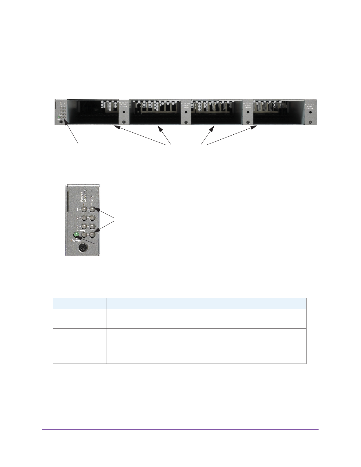
Product Name & Model
Front Panel and LEDs
The following figures show the front panel of the RPS4000 v2. The front panel contains a set
of power module LEDs for each power module slot.
APS power module slotsRPS status LEDs
Figure 1. RPS front panel
APS Power Module
status LEDs
RPS Power LED
Figure 2. RPS status LEDs
Table 1. LED description
Label Color Activity Description
PWR (Power) Green On Power is being provided to the RPS4000.
Power Module
Status
Green On An APS1000W is present and working properly.
Yellow On An APS1000W is present and is not working properly.
Off Off There is no APS1000W present.
Introduction
5
Page 6
Product Name & Model
Table 1. LED description (continued)
Label Color Activity Description
RPS Port Status Green On The device is a B type design and the APS1000W in the
corresponding RPS port and Power Module slot is
supplying power to the device.
Blinking The device is a B type design but the APS1000W in the
corresponding RPS port and Power Module slot is not
supplying power to the device. Power is being supplied
by the APS1000W in a different Power Module slot.
Yellow On The device is an A type design, and the APS1000W is
providing power to the device.
Blinking The device is an A type design, but the APS1000W is not
supplying power to the device.
Off Off No power is being supplied to the device or the device is
not recognized.
Rear Panel
The RPS4000 v2 rear panel has four RPS ports, four sets of Type and CS configuration
switches, and an AC power receptacle for the RPS4000 v2 (AC power cord supplied).
RPS port RPS configuration switches AC power receptacle
Figure 3. RPS4000 v2 rear panel
Safety Instructions
Use the following safety guidelines to ensure your own personal safety and to help protect
your system from potential damage.
To reduce the risk of bodily injury, electrical shock, fire, and damage to the equipment,
observe the following precautions.
• Observe and follow service markings:
- Do not service any product except as explained in your system documentation.
- Opening or removing covers that are marked with the triangular symbol with a
lightning bolt can expose you to electrical shock. Only a trained service technician
should service components inside these compartments.
Introduction
6
Page 7

Product Name & Model
• If any of the following conditions occur, unplug the product from the electrical outlet and
replace the part or contact your trained service provider:
- The power cable, extension cable, or plug is damaged.
- An object has fallen into the product.
- The product has been exposed to water.
- The product has been dropped or damaged.
- The product does not operate correctly when you follow the operating
instructions.
• Keep your system away from radiators and heat sources. Also, do not block cooling
vents.
• Do not spill food or liquids on your system components, and never operate the product in
a wet environment. If the system gets wet, see the appropriate section in your
troubleshooting guide or contact your trained service provider.
• Do not push any objects into the openings of your system. Doing so can cause fire or
electric shock by shorting out interior components.
• Use the product only with approved equipment.
• Allow the product to cool before removing covers or touching internal components.
• Operate the product only from the type of external power source indicated on the
electrical ratings label. If you are not sure of the type of power source required, consult
your service provider or local power company.
• To help avoid damaging your system, be sure that the voltage selection switch (if
provided) on the power supply is set to match the power available at your location:
- 115 volts (V), 60 hertz (Hz) in most of North and South America and some Far
Eastern countries such as South Korea and Taiwan
- 100 V, 50 Hz in eastern Japan and 100 V, 60 Hz in western Japan
- 230 V, 50 Hz in most of Europe, the Middle East, and the Far East
• Also, be sure that attached devices are electrically rated to operate with the power
available in your location.
• Use only approved power cables. If you have not been provided with a power cable for
your system or for any AC-powered option intended for your system, purchase a power
cable that is approved for use in your country. The power cable must be rated for the
product and for the voltage and current marked on the product’s electrical ratings label.
The voltage and current rating of the cable should be greater than the ratings marked on
the product.
• To help prevent electric shock, plug the system and peripheral power cables into properly
grounded electrical outlets.
• The peripheral power cables are equipped with three-prong plugs to help ensure proper
grounding. Do not use adapter plugs or remove the grounding prong from a cable. If you
must use an extension cable, use a three-wire cable with properly grounded plugs.
• Observe extension cable and power strip ratings. Make sure that the total ampere rating
of all products plugged into the extension cable or power strip does not exceed 80
percent of the ampere ratings limit for the extension cable or power strip.
Introduction
7
Page 8

Product Name & Model
• To help protect your system from sudden, transient increases and decreases in electrical
power, use a surge suppressor, line conditioner, or uninterruptible power supply (UPS).
• Position system cables and power cables carefully; route cables so that they cannot be
stepped on or tripped over. Be sure that nothing rests on any cables.
• Do not modify power cables or plugs. Consult a licensed electrician or your power
company for site modifications.
• Always follow your local and national wiring rules.
Introduction
8
Page 9

2. Hardware Installation
This chapter explains how to install the RPS.
This chapter contains the following sections:
• Package Contents
• Protecting against Electrostatic Discharge
• Unpack the Hardware
• Installation
• Connect Equipment to the RPS4000 v2
• RPS4000 v2 Modes of Operation
2
9
Page 10

NETGEAR Managed Switch
Package Contents
The package contains the following items:
• RPS4000 v2
• Power cord
• Rubber footpads for tabletop installation
• Rack-mounting kit
• Resource CD: The CD includes these documents or links to access them:
- RPS4000 v2 Installation Guide
- This hardware installation guide
Protecting against Electrostatic Discharge
WARNING:
Static electricity can harm delicate components inside your system.
To prevent static damage, discharge static electricity from your
body before you touch any of the electronic components, such as
the microprocessor. You can do so by periodically touching an
unpainted metal surface on the switch.
You can also take the following steps to prevent damage from electrostatic discharge (ESD):
1. When unpacking a static-sensitive component from its shipping carton, leave it in the
antistatic package until you are ready to install it. Just before unwrapping the antistatic
package, discharge static electricity from your body.
2. Before moving a sensitive component, place it in an antistatic container or package.
3. Handle all sensitive components in a static-safe area. If possible, use antistatic floor pads,
workbench pads, and an antistatic grounding strap.
Unpack the Hardware
Check the contents of the box to make sure that all items are present before installing
the RPS:
1. Place the container on a clean flat surface and cut all straps securing the container.
2. Unpack the hardware from the box.
Carefully remove the hardware and place it on a secure and clean surface. See Select a
Location on page 11.
3. Remove all packing material.
Hardware Installation
10
Page 11

NETGEAR Managed Switch
4. Make sure that all items are present. See Package Contents on page 10.
Note: If any item is found missing or damaged, contact your local
NETGEAR reseller for replacement.
5. Inspect the products and accessories for damage. Report any damage immediately.
Installation
Install the equipment in the sequence presented in this section:
1. Select a location. See Select a Location on page 11.
2. Install the switch. See Install the RPS on page 12.
3. Check the installation. See Check the Installation on page 13.
4. Apply power and check the LEDs. See Connect to Power and Check the LEDs on page 14.
Select a Location
The RPS can be mounted in a standard 19-inch (48.26-centimeter) rack or left freestanding
(placed on a tabletop).
The site where you install the RPS can affect its performance. Before installing the switch or
switches, make sure that the chosen installation location meets the following site
requirements.
Table 2. Site requirements for RPS location
Requirements
Mounting Desktop installations: Provide a flat table or shelf surface.
Rack-mount installations: Use a 19-inch (48.3-centimeter) EIA standard
equipment rack that is grounded and physically secure. You need the
rack-mount kit supplied with the RPS.
Access Locate the RPS in a position that lets you access the front and rear connections
and view the front panel LEDs.
Power source Provide a power source within 6 feet (1.8 meters) of the installation location.
Power specifications for the RPS are shown in Appendix A, Technical
Specifications. Be sure that a wall switch does not control the AC outlet. A wall
switch can accidentally turn off power to the outlet and the RPS.
Environment Install the RPS in a site free from strong electromagnetic field generators (such
as motors), vibration, dust, and direct exposure to sunlight.
Temperature The ambient RPS operating temperature range is 0º to 50ºC (32º to 122ºF).
Keep the RPS away from heat sources such as direct sunlight, warm air
exhausts, hot-air vents, and heaters.
Hardware Installation
11
Page 12

NETGEAR Managed Switch
Table 2. Site requirements for RPS location
Requirements
Operating humidity Install the RPS in a dry area with a maximum relative humidity of 90%,
noncondensing.
Ventilation Do not restrict airflow by covering or obstructing air inlets on the sides of the
RPS. Keep at least 2 inches (5.08 centimeters) free on all sides for cooling. Be
sure that there is adequate airflow in the room or wiring closet where you intend
to install the RPS.
Install the RPS
You can install the RPS on a flat surface or in a standard 19-inch rack.
Install the RPS on a Flat Surface
The RPS ships with four self-adhesive rubber footpads. Stick one rubber footpad on each
of the four concave spaces on the bottom of the RPS. The rubber footpads cushion the
RPS against shock and vibrations.
Install the Switch in a Rack
To install the RPS in a rack using the 19-inch rack-mount kit supplied with the RPS:
1. Attach the supplied mounting brackets to the side of the RPS.
2. Use the provided Phillips head screws to fasten the brackets to the sides of the
RPS.
Mounting
bracket
Hardware Installation
12
Page 13

NETGEAR Managed Switch
3. Tighten the screws with a No. 1 Phillips screwdriver to secure each bracket.
4. Align the bracket and rack holes. Use two pan-head screws with nylon washers to
fasten each bracket to the rack.
5. Tighten the screws with a No. 2 Phillips screwdriver to secure the switch in the rack.
6. Tighten the screws with a No. 2 Phillips screwdriver to secure the switch in the wall.
Check the Installation
Perform the following checks Before you apply power:
1. Inspect the equipment thoroughly.
2. Verify that all cables are installed correctly.
3. Check cable routing to ensure that cables are not damaged and do not create a safety
hazard.
4. Be sure that all equipment is mounted properly and securely.
Hardware Installation
13
Page 14

NETGEAR Managed Switch
Connect to Power and Check the LEDs
The RPS does not have an on/off switch. Apply or remove power by connecting or
disconnecting the RPS power cord. Before you connect the power cord, select an AC outlet
that is not controlled by a wall switch. A wall switch can turn off power to the RPS.
After you select an appropriate outlet, follow these steps to apply AC power:
1. Connect one end of the AC power adapter cable to the rear of the RPS, and the other
end to a grounded three-prong AC outlet.
2. Check the Power LED on the front panel of the RPS. The LED should light up in the
following sequence:
• The LED turns yellow as the RPS runs a power-on self-test (POST).
• If the RPS passes the test, the LED turns green. The RPS is working and ready to
pass data.
• If the POST fails, the Power LED blinks yellow.
If the Power LED does not light up, check that the power cable is plugged in correctly and
that the power source is good. For help with troubleshooting, see
Troubleshooting.
Chapter 3,
Connect Equipment to the RPS4000 v2
To connect a device to the RPS:
1. Disconnect the AC power cord from the switch or device.
2. Connect one end of the NETGEAR RPS cable to the RPS connector on the switch rear
panel.
3. Connect the other end of the NETGEAR RPS cable to the RPS4000 v2 rear panel RPS port
connector.
4. Reconnect the AC power cord to the switch or device.
5. Apply power to the RPS4000 v2 by connecting the power cord to the RPS4000 v2 power
connect in the front panel and to an AC powered outlet.
6. Apply power to the power module by connecting the power cord to the module power
connect in the front panel and to an AC powered outlet.
The RPS is working properly when all its front panel LEDs are lit as specified in Front Panel
and LEDs on page 5. If it is not, see Chapter 3, Troubleshooting.
Hardware Installation
14
Page 15

NETGEAR Managed Switch
WARNING:
Do not remove the RPS cable from the RPS or the powered device
when the connected device is on. First power the device off.
Second, remove the power cord from the power module. Remove
the device RPS power cable.
RPS4000 v2 Modes of Operation
The RPS4000 v2 rear panel has two slide switches for each of the four RPS ports. Each slide
switch has two positions, left and right. The slide switches control how the RPS4000 v2
provides power to the client switches.
RPS configuration switches
Use the Type and CS slide switches to configure operating modes for the RPS4000 v2.
There are seven operating modes.
Table 3. Maximum output per mode
Mode Type/CS Setting 11VDC (120VAC/240VAC) 56VDC (120VAC/240VAC) Application
1 A/Off 120W/120W 600W/600W PoE or Non-PoE
2 A/On 700W/800W 0W Non-PoE only
3 B/Off 0W 750W/930W PoE or Non-PoE
4 B/On 0W 1500W/1860W PoE or Non-PoE
5 B/On 0W 375W/465W PoE or Non-PoE
6 B/On 0W 1120W/1550W PoE or Non-PoE
7 All four ports not the same 120W/120W 0W Non-PoE only
Hardware Installation
15
Page 16

NETGEAR Managed Switch
Note: Modes one through six require all four RPS ports to have the same
Type/CS setting.
Mode One
This mode supports Type A RPS devices such as GSM732xxSv1. One APS1000W PSU
inside an RPS4000 v2 power bank supports one RPS port delivering power to an
individual switch when a connected device is detected.
RPS4000 v2-provided PoE power replaces the switch's internal power supply when the
RPS4000 v2 is connected to the switch.
standby power supply. In this mode, APS1000W must be installed in the corresponding
power module slot.
If a Type B device is connected to RPS4000 v2 in this mode, the device will only receive
maximum power as indicated in table 3.
The power supply inside the switch becomes a
One RPS cabled to one switch and one APS1000W dedicated to one switch are required
to use this mode.
Figure 4. Mode One Diagram
Mode Two
This mode can be used for both Type A and Type B RPS devices such as the M5300
series or GSM73xxv1 series. The RPS port only delivers system power (12v) to a device
when a connected device is detected. This mode allows one APS1000W to backup four
switches simultaneously.
Hardware Installation
16
Page 17

NETGEAR Managed Switch
RPS4000 v2-provided PoE power replaces the switch's internal power supply when the
RPS4000 v2 is connected to the switch, and the power supply inside the switch becomes
a standby power supply. In this mode, APS1000W can be installed in any slot, but only
the slot it is installed in will be used.
If Type B device is connected to RPS4000 in this mode, the device will only receive
maximum power as indicated in table 3.
One RPS cable to one switch and one APS1000W shared by all connected switches are
required in this mode.
Figure 5. Mode Two Diagram
Mode Three
The main difference between the Type A setting and the Type B setting is that Type B
devices support I2C bus communication. Type B devices can communicate what power
load they require, providing more dynamic power allocation when the Type B setting is
used.
On Type B devices such as the M5300 series switch, each RPS port delivers power from
APS1000W to the connected switches. For each RPS port to provide power, its
each
corresponding APS1000 PSU must be installed inside the RPS4000 chassis.
Hardware Installation
17
Page 18

NETGEAR Managed Switch
One RPS cable to one switch and one APS1000W shared by all connected switches are
required to use this mode.
Figure 6. Mode Three Diagram
Mode Four
This mode supports Type B RPS devices such the M5300 series switches. RPS ports
deliver power to devices when the RPS4000v2 detects a connected Type B device over
the I2C bus.
In this mode, the RPS port can output a maximum 1440W of PoE power to devices when
2 power modules are present and work well in the same group. RPS port 1 and port 3
take priority when both ports 1 and 3 and ports 2 and 4 are connected to devices at the
same time. Ports 2 and 4 receive 1440W of power when ports 1 or 3 do not have devices
connected.
Note: RPS Ports 1 and 3 take priority. The RPS4000 v2 will cut-off output
power to ports 2 and 4 if devices are connected to ports 1 and 3.
Hardware Installation
18
Page 19

NETGEAR Managed Switch
One RPS cable to one switch and one APS1000W shared by all connected switches are
required to use this mode.
Figure 7. Mode Four Diagram
Mode Five
This mode supports Type B RPS devices such the M5300 series switches. RPS ports
deliver power to devices when the RPS4000v2 detects a connected Type B device over
the I2C bus.
In this mode, one APS1000W will provide power to 2 RPS ports in the same group.
Hardware Installation
19
Page 20

NETGEAR Managed Switch
One RPS cable to one switch and one APS1000W shared by all connected switches are
required to use this mode.
Figure 8. Mode Five Diagram
Mode Six
This mode supports NETGEAR chassis and switches that support the sharing feature,
such as the M6100 chassis switch. The RPS will combine power from two adjacent APS
units to one switch.
In this mode, one group’s RPS port outputs a maximum of 1550W (with ACin=220V) of
PoE power to devices when 2 power modules are present and work well in the same
group. RPS port 1 and port 3 take priority when both ports 1 and 3 and ports 2 and 4 are
connected to devices at the same time. Ports 2 and 4 receive 1440W of power when
ports 1 or 3 do not have devices connected.
Note: RPS Ports 1 and 3 take priority. The RPS4000 v2 will cut-off output
power to ports 2 and 4 if devices are connected to ports 1 and 3.
Hardware Installation
20
Page 21

NETGEAR Managed Switch
This mode requires two RPS cables to two RPS ports on the M6100 chassis switch and
all RPS4000 slots populated with APS1000W units.
Figure 9. Mode Six Diagram
Mode Seven
In this mode, RPS4000 v2 delivers system power to connected devices when the Type
and CS setting for each RPS port are not the same.This mode functions as a fall back
when the mode setting is set incorrectly. All other APS1000W do not provide power in this
mode.
Hardware Installation
21
Page 22

NETGEAR Managed Switch
One RPS cable to one switch and one or more APS1000W populated in the RPS4000 v2
slots are required to use this mode.
Figure 10. Mode Seven Diagram
Note: The RPS will power off in all modes if two APS1000W units in the
same group are not operating in the same range (e.g. one using
110VAC and another using 220VAC) and the two APS units are
paired together to offer more power.
Note: RPS will power off if all port are connected to a Type A RPS device to
when the RPS4000 v2 Type setting is set to Type B.
Hardware Installation
22
Page 23

3. Troubleshooting
Troubleshooting Chart
The following table lists symptoms, causes, and solutions of possible problems.
Table 4. Troubleshooting chart
Problem Cause Solution
Power LED is off. No power is received. Check the power cord connections for the switch
3
at the switch and the connected device.
Make sure that all cables used are correct and
comply with Ethernet specifications.
RPS port LED is off or
incorrect.
Incorrect switch selections. Check the operating mode and CS switch
selection.
23
Page 24

A. Technical Specifications
Technical Specifications
Table 5. Technical specifications
Feature Description
Environment Operating:
• T
emperature: 32° to 122°F (0° to 50°C)
• Humidity: 90% maximum relative humidity
• Altitude: 10,000 ft (3,000 m) maximum
Storage:
• T
emperature: – 4° to 158°F (–20° to 70°C)
• Humidity: 95% maximum relative humidity
• Altitude: 10,000 ft (3,000 m) maximum
A
, noncondensing
, noncondensing
Mean time between
failure (MTBF)
Electromagnetic emissions and
immunity
Safety CE mark, commercial, CSA certified (CSA 22.2 #950), UL listed (UL
168,208 hours (~19.2 years) @ 25°C
55,879 hours (~6.4 years) @ 55° C
CE mark, commercial, FCC Part 15 Class A, VCCI Class A, Class A EN
55022 (CISPR 22) Class
1950)/cUL IEC950/EN60950
A, Class A C-Tick, EN 50082-1, EN 55024
24
 Loading...