

Page 1
Installation
Redundant Power System and Power Bank
RPS4000 v2
The Redundant Power System and Power Bank RPS4000 v2 provides power
system redundancy to external devices such as NETGEAR chassis switches,
managed switches or smart switches that have an RPS capability.
Each RPS4000 v2 has four power module slots and a maximum output of
4000W when four APS1000W power modules are installed. The RPS4000
v2 supports switches using both A type and B type RPS designs. The
RPS4000 v2 acts as a redundant power system in 12 VDC power systems
and acts as a power bank in PoE (56 VDC) power systems.
Package Contents
This package includes:
• Redundant Power System and Power Bank RPS4000 v2
• AC power cable
• RPS cable, 60 cm (23.6 in.),16 pin
LEDs
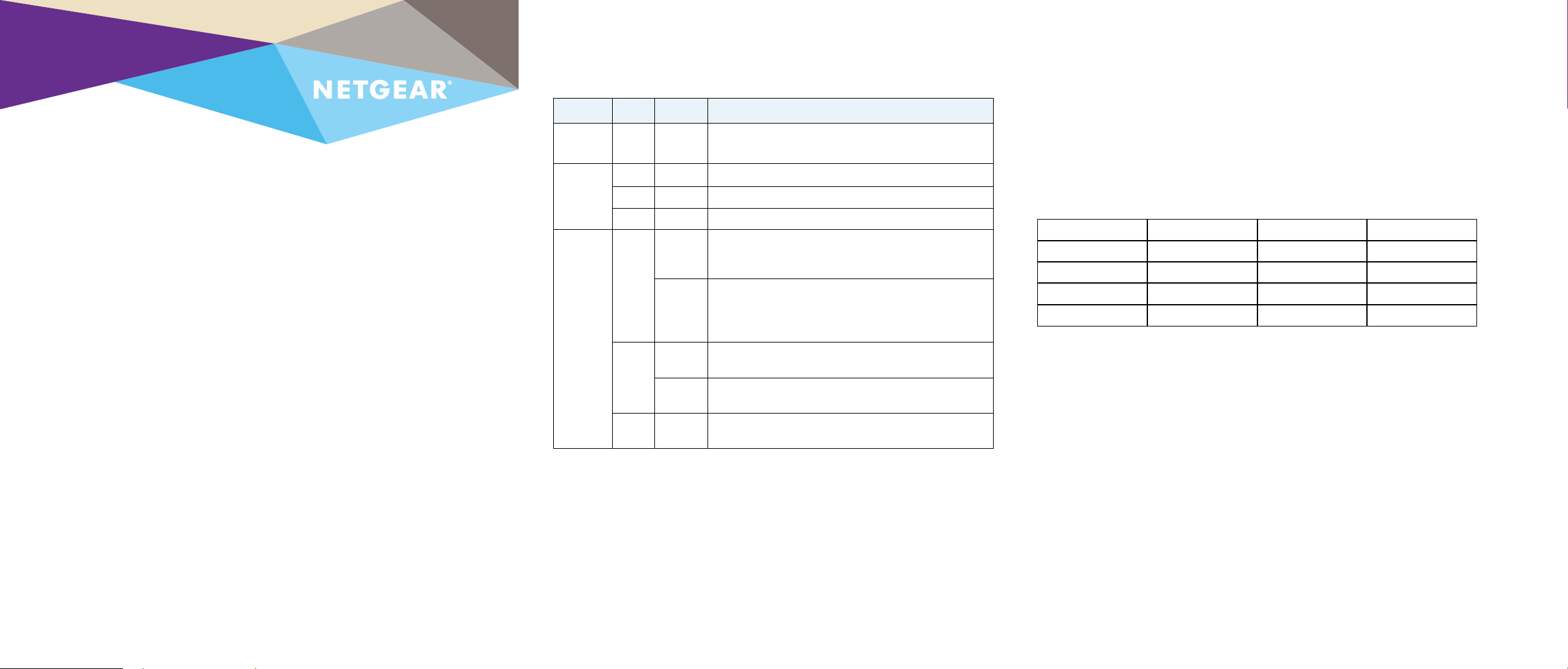
Power system indicators are listed in the following table:
Label Color Activity Description
PWR
(Power)
Power
Module
Status
RPS Port
Status
Green On Power is being provided to the RPS4000.
Green On An APS1000W is present and working properly.
Yellow On An APS1000W is present and is not working properly.
O O There is no APS1000W present.
Green On The device is a B type design and the APS1000W in
the corresponding RPS port and Power Module slot is
supplying power to the device.
Blinking The device is a B type design but the APS1000W in the
corresponding RPS port and Power Module slot is not
supplying power to the device. Power is being supplied by
the APS1000W in a dierent Power Module slot.
Yellow On The device is an A type design, and the APS1000W is
providing power to the device.
Blinking The device is an A type design, but the APS1000W is not
supplying power to the device.
O O No power is being supplied to the device or the device is
not recognized.
RPS Ports
Each RPS port on the RPS4000W can provide a maximum of 1440W @ 56 VDC
and 200W @ 11 VDC. Output power depends on the power modules installed and
the Switch Type (Type) and Current Share (CS) switch settings.
The following switches are of the A RPS type and must use the A type setting.
Note: The Type setting has changed for v2. Type A is the same as Type Old, and
Type B is the same as Type New.
FSM7328S GSM7248v2 GSM7224P GSM7352S V2H1
FSM7352S GSM7212P GSM7228PS V1H1 GSM752PS V1H1
FSM7226RS GSM7212F GSM7328 V1H1 GSM7328FS V1H1
FSM7250RS GSM7224R GSM7328 V2H1
GSM7224v2 GSM7248R GSM7352S V1H1
For other switches, refer to the switch hardware installation guide on the NETGEAR
support website to determine the RPS type.
Install the RPS4000 v2
Install the RPS4000 v2 in a standard 19-inch rack.
WARNING: Do not stack equipment, or place equipment in tight spaces or in
drawers. Be sure that your equipment is surrounded by at least 2 inches (5 cm) of
air space.
Install the RPS4000 v2 in a Rack
To install the RPS4000 v2 in a rack, you need the 19-inch rack-mount kit supplied
with your RPS4000 v2.
Page 2
¾ To install the RPS4000 v2:
1. Attach the supplied mounting brackets to the side of the RPS4000 v2.
2. Use the provided Phillips head screws to fasten the brackets to the sides
of the RPS4000 v2.
Connect Switches to the RPS4000 v2
WARNING: To prevent an electrical hazard, make sure that the RPS AC
power cord is not connected to the RPS before you install an APS1000W
power module or connect the RPS to a switch.
1. Make sure an APS1000W power module is plugged into the
corresponding power module slot before you connect a switch to an
RPS4000 v2 RPS port.
2. Remove power to the APS1000W before connecting the switch.
3. Based on the RPS specification for the device, select the Type and CS
switch settings. Refer to the RPS4000 v2 Hardware Installation Guide
for configuration instructions for the RPS4000 v2.
4. Connect the device to the RPS port on the RPS4000 v2 using a
NETGEAR RPS cable (60 cm, 16 pin).
5. Restore power to the APS1000W supplying the switch.
Support
Thank you for selecting NETGEAR products.
Aer installing your device, locate the serial number on the label of your
product and use it to register your product at https://my.netgear.com.
You must register your product before you can use NETGEAR telephone
support. NETGEAR recommends registering your product through the NETGEAR
website. For product updates and web support, visit
http://support.netgear.com.
NETGEAR recommends that you use only the ocial NETGEAR support
resources.
For the current EU Declaration of Conformity, visit
http://support.netgear.com/app/answers/detail/a_id/11621/.
3. Tighten the screws with a No. 1 Phillips screwdriver to secure each
bracket.
4. Align the bracket and rack holes. Use two pan-head screws with nylon
washers to fasten each bracket to the rack.
5. Tighten the screws with a No. 2 Phillips screwdriver to secure the
switch in the rack.
Check the Installation
Before you apply power, perform the following checks:
1. Inspect the equipment thoroughly.
2. Verify that all cables are installed correctly.
3. Check cable routing to ensure that cables are not damaged and do not
create a safety hazard.
4. Be sure that all equipment is mounted properly and securely.
November 2014
NETGEAR, Inc.
350 East Plumeria Drive
San Jose, CA 95134, USA
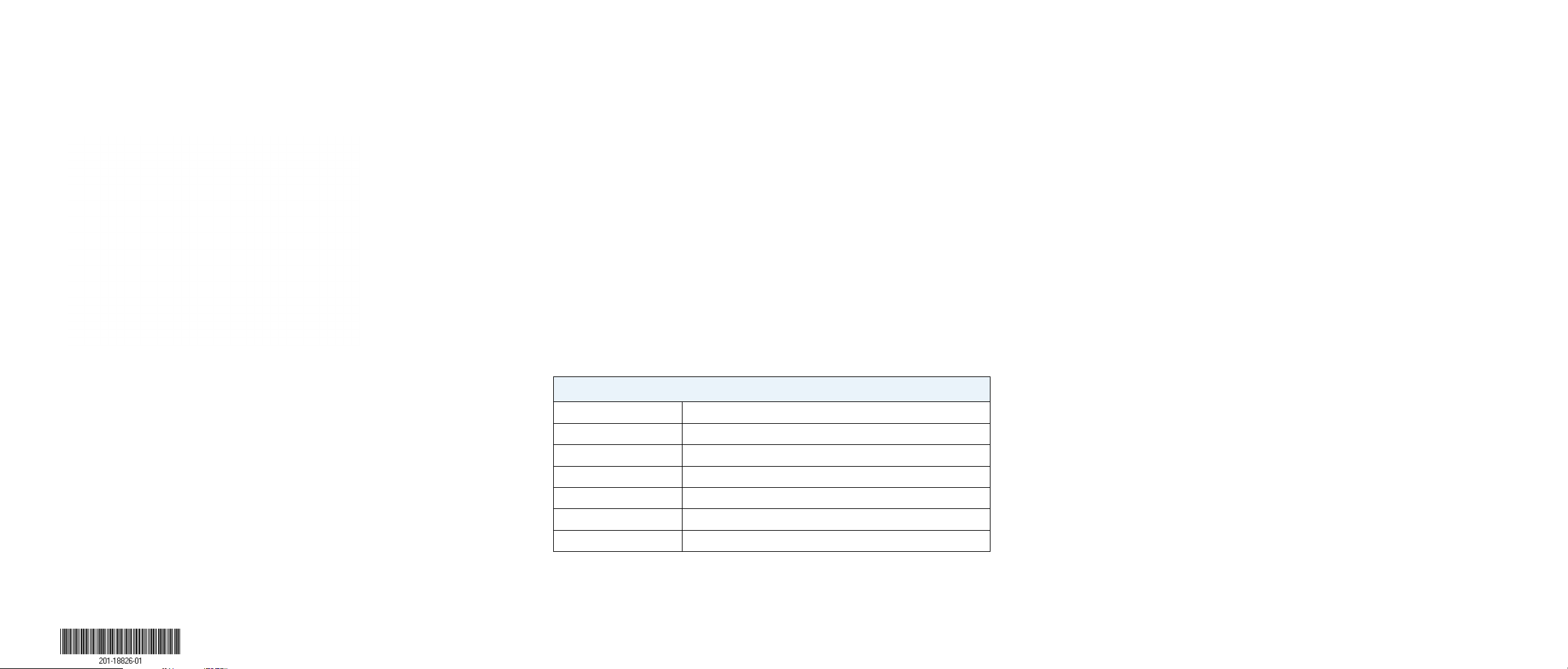
Specifications
Technical Specifications
RPS port interface 4 NTGR RPS ports, 16 pin
Power 100–240 VAC, 50–60 Hz
Dimensions (H x W x D) 1.7 x 17.32 x 16.92 in. (43 x 440 x 430 mm)
Weight 12.8 lbs (5.8 Kg)
Operating temperature 0° to 50°C (32° to 104°F)
Operating humidity 90% maximum relative humidity, noncondensing
Safety agency approvals UL, LVD, CB
For regulatory compliance information, visit
http://www.netgear.com/about/regulatory/.
See the regulatory compliance document before connecting the power supply.
NETGEAR, the NETGEAR logo, and Connect with Innovation are trademarks and/or registered
trademarks of NETGEAR, Inc. and/or its subsidiaries in the United States and/or other countries.
Information is subject to change without notice. © NETGEAR , Inc. All rights reserved.
 Loading...