

Page 1

Reference Manual for the
Model RP614 v2 Web
Safe Router
NETGEAR, Inc.
4500 Great America Parkway
Santa Clara, CA 95054 USA
SM-RP614NA-2
Version 4.12
February 2003
Page 2

© 2002 by NETGEAR, Inc. All rights reserved.
Trademarks
NETGEAR is a trademark of Netgear, Inc.
Microsoft, Windows, and Windows NT are r egistered trademarks of Microsoft Corporation.
Other brand and product names are registered t r ademarks or trademarks of their respective ho ld ers.
Statement of Conditions
In the interest of improving internal design, operational function, and/or reliability, NETGEAR reserves the right to
make changes to the products described in this document without notice.
NETGEAR does not assume any liab ility that may occur due to the use or ap plication of the product(s) or circui t
layout(s) desc ribed herein.
Federal Communications Commission (FCC) Compliance Notice: Radio Frequency Notice
This equipment has been tested and foun d to comply with the limits for a Class B dig it a l device, pursua nt to
part 15 of the FCC Rules. These limits are designed to provide reasonable protection against harmful interference in a
residential in stallation. This equ ipment generates, uses, and can radiate radio frequency energy and, if not installed and
used in accordance with the instructio ns, may c ause harmfu l interference to radio commu nicatio ns. However, there is no
guarantee that interference will not occur in a particular installation. If this equipment does cause harmful interference to
radio or television reception, which can be determined by turning the equipment off and on, the user is encouraged to try
to correct the interference by one or more of the following measures:
• Reorient or relocate the receivin g antenna.
• Increase the separation between the equipment and receiver.
• Connect the equipment into an outlet on a circuit different from that to which th e receiver is connected.
• Consult the dealer or an experienced radio/TV technician for hel p.
EN 55 022 Declaration of Conformance
This is to certify that the Model RP614 v2 Web Safe Router is shielded against the generation of radio interference in
accordance with the appl ic ation of Co un cil Dire c tiv e 89/ 336/E EC, Article 4a. Conformity is declared by the a pplic atio n
of EN 55 022 Class B (CISPR 22).
ii
Page 3

Bestätigung des Herstellers/Importeurs
Es wird hiermit bestätigt, daß das Model RP614 v2 Web Safe Router gemäß der im BMPT-AmtsblVfg 243/1991 und Vfg
46/1992 aufgeführten Bestimmungen entstört ist. Das vorschriftsmäßige Betreiben einiger Geräte (z.B. Testsender) kann
jedoch gewissen Beschränkungen unterliegen. Lesen Sie dazu bitte die Anmerkungen in der Betriebsanleitung.
Das Bundesamt für Zulassungen in der Telekommunikation wurde davon unterrichtet, daß dieses Gerät auf den Mar kt
gebracht wurde und es ist berechtigt, die Serie auf die Erfüllung der Vorschriften hin zu überprüfen.
Certificate of the Manufacturer/Importer
It is hereby certified that the Model RP614 v2 Web Safe Router has been suppressed in accordance with the conditions
set out in the BMPT-AmtsblVfg 24 3/1991 and Vfg 46/1992. The operation o f some equipment (for example, test
transmitters) in accordance with the regulations may, however, be subject to certain restrictions. Please refer to the notes
in the operating instructions.
Federal Office for Telecommunications Approvals has been notified of the placing of this equipment on the market
and has been granted the right to test the series for compliance with the regulations.
Voluntary Control Council for Interference (VCCI) Statement
This equipment is in the second category (information equipment to be used in a residential area or an adjacent area
thereto) and conforms to the standards set by the Voluntary Control Council for Interference by Data Processing
Equipment and Electroni c Office Machines aimed at preventing radio interference in such residential areas.
When used near a radio or TV receiver, it may become the cause of radio interference.
Read instructions for correct handling.
Customer Support
Refer to the Support Information Card that shipped with your Model RP614 v2 Web Safe Router.
World Wide Web
NETGEAR maintains a World Wide Web home page that you can access at the universal resource locator (URL)
http://www.netgear.com. A direct connection to the Internet and a Web browser such as Internet Explorer
or Netscape are required.
iii
Page 4

iv
Page 5

Contents
Preface
About This Manual
Chapter 1
Introduction
Key Features of the Router ............................................................................................1-1
A Powerful, True Firewall with Content Filtering ......................................................1-2
Security .................................................................................................................... 1-2
Autosensing Ethernet Connections with Auto Uplink™ ...........................................1-3
Extensive Protocol Support ......................................................................................1-3
Easy Installation and Management ..........................................................................1-4
Maintenance and Support ........................................................................................1-4
Package Contents ..........................................................................................................1-4
The Router’s Front Panel .........................................................................................1-5
The Router’s Rear Panel .........................................................................................1-6
Chapter 2
Connecting the Router to the Internet
What You Will Need Before You Begin ...........................................................................2-1
Cabling and Computer Hardware Requirements .....................................................2-1
Computer Network Configuration Requ irem ents ............ ...... ...... ....... ...... ....... ...... ...2-1
Internet Configuration Requirements .......................................................................2-2
Where Do I Get the Internet Configuration Parameters? .........................................2-2
Worksheet to Record Your Internet Connection Information ....................................2-3
Connecting the Model RP614 v2 Web Safe Router .......................................................2-4
PPPoE Wizard-Detected Option ..............................................................................2-8
AOL Wizard-Detected Options ....... ....... ...... ....... ...... ....................................... ...... ...2-9
Telstra Bigpond Cable Wizard-Detected Option .....................................................2-13
Dynamic IP Wizard-Detected Option .....................................................................2-14
Fixed IP Account Wizard-Detected Option .. ....... ...... ....... ...... .................................2-1 5
Manually Configuring Your Internet Connection ...........................................................2-16
Contents v
Page 6

Chapter 3
Content Filtering
Content Filtering Overview ....................................... ...... ....... ...... ...... ....... ...... ....... .........3-1
Blocking Access to Internet Sites ...................................................................................3-2
Blocking Access to Internet Services .............................................................................3-3
Configuring a User Defined Service .........................................................................3-4
Configuring Services Blocking by IP Address Range ..............................................3-5
Scheduling When Blocking Will Be Enforced .................................................................3-5
Stateful Packet Inspection (SPI), Java, ActiveX, and Cookies Blocking Options ...........3-6
Using SPI .................................................................................................................3-6
Using Java, ActiveX, and cookies Filtering. .............................................................3-7
Viewing Logs of Web Access or Attempted Web Access ...............................................3-7
Configuring E-Mail Alert and Web Access Log Notifications ..........................................3-9
Chapter 4
Maintenance
Viewing Router Status Information .................................................................................4-1
Viewing a List of Attached Devices .................................................................................4-5
Upgrading the Router Software ......................................................................................4-5
Configuration File Management .....................................................................................4-6
Restoring and Backing Up the Configuration ...........................................................4-7
Erasing the Configuration .........................................................................................4-8
Changing the Configuration Password ...........................................................................4-8
Chapter 5
Advanced Configuration of the Router
Configuring for Port Forwarding to Local Servers ..........................................................5-1
Adding a Custom Service .........................................................................................5-2
Editing or Deleting a Port Forwarding Entry .............................................................5-3
Local Web and FTP Server Example .......................................................................5-3
Multiple Computers for Half Life, KALI or Quake III Example ..................................5-3
Configuring the WAN Setup Options ..............................................................................5-4
Setting Up a Default DMZ Server .............................................................................5-4
Respond to Ping on Internet WAN Port ...................................................................5-5
Setting the MTU Size ...............................................................................................5-6
Using the LAN IP Setup Options ....................................................................................5-6
Configuring LAN TCP/IP Setup Parameters ............................................................5-7
vi Contents
Page 7

Using the Router as a DHCP server ........................................................................5-8
Using Address Reservation ......................................................................................5-9
Using a Dynamic DNS Service .......................................................................................5-9
Configuring Static Routes .............................................................................................5-10
Enabling Remote Management Access .......................................................................5-13
Using Universal Plug and Play (UPnP) ........................................................................5-14
Chapter 6
Troubleshooting
Basic Functioning ........................................ ...... ....... ...... ....................................... ...... ...6-1
Power LED Not On ...................................................................................................6-1
Test LED Never Turns On or Test LED Stays On .....................................................6-2
LAN or WAN Port LEDs Not On ...............................................................................6-2
Troubleshooting the Web Configuration Interface ..........................................................6-3
Troubleshooting the ISP Connection ..............................................................................6-4
Troubleshooting a TCP/IP Network Using a Ping Utility .................................................6-5
Testing the LAN Path to Your Router .......................................................................6-5
Testing the Path from Your PC to a Remote Device ................................................6-6
Restoring the Default Configuration and Password ........................................................6-7
Problems with Date and Time .........................................................................................6-7
Appendix A
Technical Specifications
Specifications for the Model RP614 v2 .......................................................................... A-1
Appendix B
Networks, Routing, and Firewall Basics
Related Publications ...................................................................................................... B-1
Basic Router Concepts ............ ....... ...... ....................................... ...... ....... ...... ....... ...... .. B-1
What is a Router? ................................................................................................... B-2
Routing Information Protocol ................................................................................... B-2
IP Addresses and the Internet ................................................................................. B-2
Netmask ...................... ................................................................ ............................ B -4
Subnet Addressing .................................................................................................. B-5
Private IP Addresses ............................................................................................... B-7
Single IP Address Operation Using NAT ................................................................. B-8
MAC Addresses and Address Resolution Protocol ................................................. B-9
Related Documents ............................................................................................... B-10
Contents vii
Page 8

Domain Name Server ............................................................................................ B-10
IP Configuration by DHCP .....................................................................................B-11
Internet Security and Firewalls .....................................................................................B-11
What is a Firewall? .................................................................................................B-11
Stateful Packet Inspection ..................................................................................... B-12
Denial of Service Attack ........................................................................................ B-12
Ethernet Cabling .......................................................................................................... B-13
Uplink Switches and Crossover Cables ................................................................ B-13
Cable Quality ......................................................................................................... B-14
Appendix C
Preparing Your Network
Preparing Your Computers for TCP/IP Networking .......................................................C-1
Configuring Windows 95, 98, and Me for TCP/IP Networking ....................................... C-2
Install or Verify Windows Networking Components ................................................. C-2
Enabling DHCP to Automatically Configure TCP/IP Settings ................................. C-4
Selecting Windows’ Internet Ac cess Metho d ..... ...... ....... ...... .................................. C-6
Verifying TCP/IP Properties ....................................................................................C-6
Configuring Windows NT4, 2000 or XP for IP Networking ............................................C-7
Configuring the Macintosh for TCP/IP Networking ......................................................C-15
Verifying the Readiness of Your Internet Account .......................................................C-18
Are Login Protocols Used? ...................................................................................C-18
What Is Your Configuration Information? .............................................................. C-18
Obtaining ISP Configuration Information for Windows Computers ....................... C-19
Obtaining ISP Configuration Information for Macintosh Computers ..................... C-20
Restarting the Network ................................................................................................C-21
Glossary
Index
viii Contents
Page 9

Preface
About This Manual
Congratulations on your purchase of the NETGEAR® Model RP614 v2 Web Safe Router.
The RP614 v2 router provides connection for multiple personal computers (PCs) to the Internet
through an external broadband access device (such as a cable modem or DSL modem) that is
normally intended for use by a single PC.
Audience
This reference manual assumes that the reader has basic to intermediate computer and Internet
skills. However, basic computer network, Internet, firewall, and VPN technologies tutorial
information is provided in the Appendices and on the Netgear website.
Typographical Conventions
This guide uses the following typographical conventions:
italics Media titles, UNIX files, commands, URLs, and directory names.
bold times roman User input
Internet Protocol (IP) First time a n abbreviated term is used.
courier font Screen text, user-typed command-line entries.
[Enter] Named keys in text are shown enclosed in square brackets. The notation
[Enter] is used for the Enter key and the Return key.
[Ctrl]+C Two or more keys that must be pressed simultaneously are shown in text
linked with a plus (+) sign.
SMALL CAPS DOS file and directory names.
About This Manual xi
Page 10
Reference Manual for the Model RP614 v2 Web Safe Router
Special Message Formats
This guide uses the following formats to highlight special messages:
Note: This format is used to highlight information of importance or special interest.
xii About This Manual
Page 11

Chapter 1
Introduction
This chapter describes the features of the NETGEAR Model RP614 v2 Web Safe Router.
Key Features of the Router
The Model RP614 v2 Web Safe Router with 4-port switch connects your local area network
(LAN) to the Internet through an external access device such as a cable modem or DSL modem.
The RP614 v2 router provides you with multiple Web content filtering options, plus browsing
activity reporting and instant alerts -- both via e-mail. Parents and network administrators can
establish restr icted acc ess polic ies based on time-of-d ay, Website a ddresses a nd address ke ywords,
and share high-speed cable/DSL Internet access for up to 253 personal computers. Network
Address Translation (NAT) protects you from hackers.
With minimum setup, you can install and use the router within minutes.
The RP614 v2 router provides the following features:
• Easy, web-based setup for installation and management
• Stateful Packet Inspection, Content Filtering, and Site Blocking Security
• Built in 4-port 10/100 Mbps Switch
• Ethernet connection to a wide area network
modem
• Extensive Protocol Support
• Login capability
• Front panel LEDs for easy monitoring of status and activity
• Flash memory for firmware upgrade
Introduction 1-1
(WAN) device, such as a cable modem or DSL
Page 12

Reference Manual for the Model RP614 v2 Web Safe Router
A Powerful, True Fire wall with Content Filtering
Unlike simple Internet sharing NAT routers, the Model RP614 v2 is a true firewall, using stateful
packet inspection to defend against hacker attacks. Its firewall features inc l ude:
• Denial of Service
(DoS) protection.
Automatically detects and thwarts DoS attacks such as Ping of Death, SYN Flood, LAND
Attack, and IP Spoofing.
• Blocks unwanted traffic from the Internet to your LAN.
• Blocks access from your LAN to Internet locations or services that you specify as off-limits.
• Logs securit y incidents.
The Model RP614 v2 will log security events such as blocked incoming traffic, port scans,
attacks, and administrator logins. You can configure the router to email the log to you at
specified inter vals. You can also configure the route r to send immedi ate alert messages to yo ur
email address or email pager whenever a significant e vent occurs.
• With its content filtering feature, the Model RP614 v2 prevents objectionable content from
reaching your PCs. The router al lows you to co ntrol access to Internet content by screenin g for
keywords within Web addresses. You can configure the router to log and report attempts to
access objectionable Internet sites.
Security
The RP614 v2 router is equipped with several features designed to maintain security, as described
in this section.
• PCs Hidden by NAT
NAT opens a temporary path to the Internet for reque sts originat ing from the local network.
Requests originating from outside the LAN are discarded, preventing users outside the LAN
from finding and directly accessing the PCs on the LAN.
• Port Forwarding with NAT
Although NAT prevents Internet locations from directly accessing the PCs on the LAN, the
router allows you to direct incoming traffic to specific PCs based on the service port number
of the incoming request, or to one designated “DMZ” host computer. You can specify
forwarding of single ports or ranges of ports.
1-2 Introduction
Page 13

Reference Manual for the Model RP614 v2 Web Safe Router
Autosensing Ethernet Connections with Auto Uplink™
With its internal 4-port 10/100 switch, the Model RP614 v2 can connect to either a 10 Mbps
standard Ethernet network or a 100 Mbps Fast Ethernet network. Both the LAN and WAN
interfaces are autosensing and capable of full-duplex or half-duplex operation.
The router incorporates Auto Uplink
TM
technology. Each Ethernet port will automatically sense
whether the Ethernet cable plugged into the port should have a ‘normal’ connection such as to a
PC or an ‘uplink’ connection such as to a switch or hub. That port will then configure itself to the
correct configuration. This feature also eliminates the need to worry about crossover cables, as
Auto Uplink will accommodate either type of cable to make the right connection.
Extensive Protocol Support
The RP614 v2 router supports the Transmission Control Protocol/Internet Protocol (TCP/IP) and
Routing Information Protocol
“Network, Routing, Firewall, and Basics.”
• IP Address Sharing by NAT
The RP614 v2 router allows several networked PCs to share an Internet account using only a
single IP address, which may be statically or dynamically assigned by your Internet service
provider (ISP). This technique, known as NAT, allows the use of an inexpensive single-user
ISP account.
• Automatic Configuration of Attached PCs by DHCP
The RP614 v2 router dynamically assigns network configuration information, including
IP, gateway, and domain name server
Dynamic Host Configuration Protocol
of PCs on your local network.
(RIP). For further information about TCP/IP, refer to Appendix B,
(DNS) addresses, to attached PCs on the LAN using the
(DHCP). T his feature greatly simplifies configuration
• DNS Proxy
When DHCP is enabled and no DNS addresses are specified, the router provides its own
address as a DNS server to the attached PCs. The router obtains actual DNS addresses from
the ISP during connection setup and forwards DNS requests from the LAN.
• PPP over Ethernet
(PPPoE)
PPPoE is a protocol for connecting remote hosts to the Internet over a DSL connection by
simulating a dial-up connection. This feature eliminates the need to run a login program such
as Entersys or WinPOET on your PC.
Introduction 1-3
Page 14

Reference Manual for the Model RP614 v2 Web Safe Router
Easy Insta ll ation and Management
You can i nst al l, configure, and oper ate the Model RP614 v2 Web Safe Router within mi nut es a ft er
connecting it to the network. The following features simplify installation and management tasks:
• Browser-based managemen t. Browser-based configuration allows you to easily configure
your router from almost any type of personal computer, such as Windows, Macintosh, or
Linux. A user-friendly Setup Wizard is provided and online help documentation is built into
the browser-based Web Management Interface.
• Smart Wizard. The RP614 v2 router automatically senses the type of Internet connection,
asking you only for the information required for your type of ISP account.
• Visual monitoring. The RP614 v2 router’s front panel LEDs provide an easy way to monitor
its status and activity.
Maintenance and Support
NETGEAR offers the following features to help you maximize your use of the RP614 v2 router:
• Flash memory for firmware upgrade
• Free technical support seven days a week, twenty-four hours a day
Package Contents
The product package should contain the following items:
• Model RP614 v2 Web Safe Router.
• AC power adapter.
• Category 5 (CAT5) Ethernet cable.
• Model RP614 v2 Resource CD, including:
— This guide.
— Application Notes and other helpful information.
— AOL v8.0 client software.
• RP614 Cable/DSL Web Safe Router Installation Guide.
• Registration and Warranty Card.
• Support Information Card.
If any of the parts are incorrect, missing, or damaged, contact your NETGEAR dealer. Keep the
carton, including the original packing materials, in case you need to return the router for repair.
1-4 Introduction
Page 15
Reference Manual for the Model RP614 v2 Web Safe Router
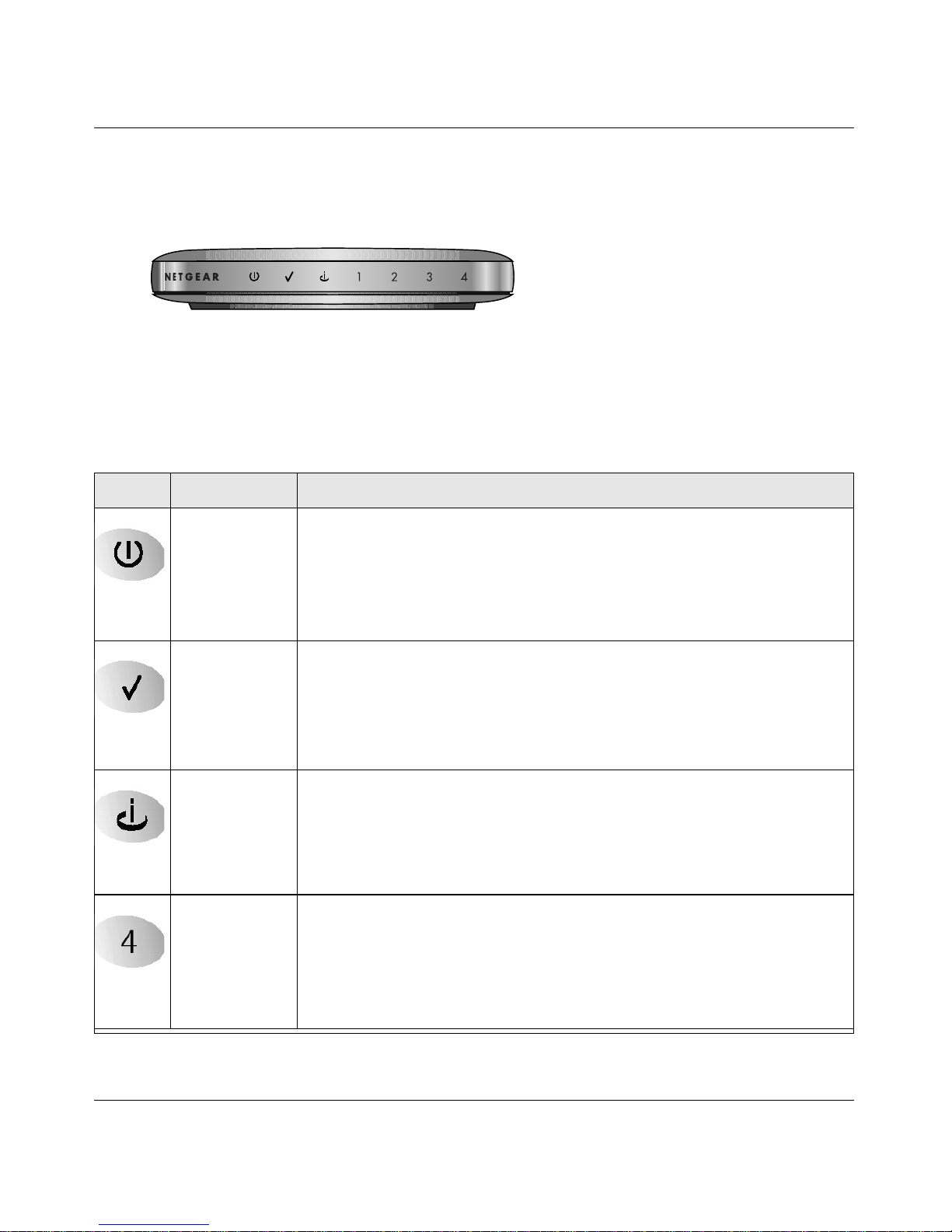
The Router’s Front Panel
The front panel of the Model RP614 v2 Web Safe Router (Figure 1-1) contains status LEDs.
Figure 1-1: RP614 Front Panel
You can use some of the LEDs to verify connections. Viewed from left to right, Table 2 describes
the LEDs on the front panel of th e router. These LEDs are green when lit.
Table 2. LED Descriptions
Label Activity Description
Power
Test
Internet
Local
On
Off
On
Off
On (Green)
Blink (Green)
On (Amber)
Blink (Amber)
Off
On (Green)
Blink (Green)
On (Amber)
Blink (Amber)
Off
Power is supplied to the router.
Power is not supplied to the router.
The system is initializing.
The system is ready and running.
The Internet (WAN) port has detected a 100 Mbps link with an attached device.
Data is being transmitted or received by the Internet port.
The Internet (WAN) port has detected a 10 Mbps link with an attached device.
Data is being transmitted or received by the Internet port.
The Internet (W AN) port in no t conne cted or the el ectric power to the devic e to
which it is connect ed is turned off.
The Local (LAN) port has detected link with a 100 Mbps device.
Data is being transmitted or received at 100 Mbps.
The Local port has detected link with a 10 Mbps device.
Data is being transmitted or received at 10 Mbps.
No link is detected on this port.
Introduction 1-5
Page 16
Reference Manual for the Model RP614 v2 Web Safe Router
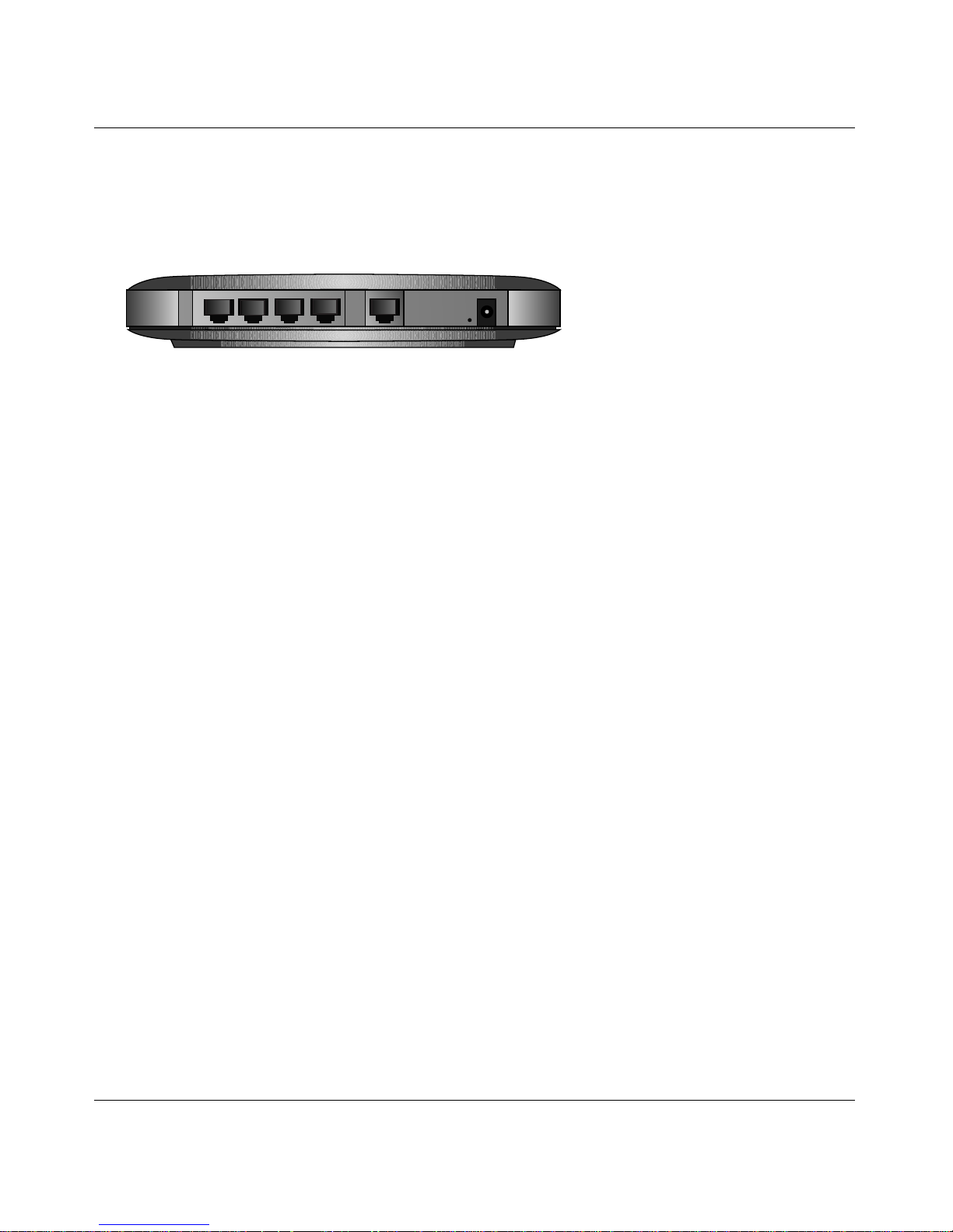
The Router’s Rear Panel
The rear panel of the Model RP614 router (Figure Figure 1-2:) contains port connections.
Figure 1-2: RP614 Rear Panel
Viewed from left to right, the rear panel contains the following fe atures:
• Four Local (LAN) Ethernet ports for connecting the router to the local PCs
• Internet (WAN) Ethernet port for connecting the router to a cable or DSL modem
• Factory Default Reset push button
• AC power adapter outlet
1-6 Introduction
Page 17

Chapter 2
Connecting the Router to the Internet
This chapter describes how to set up the router on your local area network (LAN) and connect to
the Internet. You find out how to configure your Model RP614 v2 Web Safe Router for Internet
access using the Setup Wizard, or how to manually configure your Internet connection.
What You Will Need Before You Begin
You need to prepare these three things before you begin:
1. Have active Internet service such as that provided by an cable or DSL broadband account.
2. Locate the Internet Service Provider (ISP) configuration information for your DSL account.
3. Connect the router to a cable or DSL modem and a computer as explained below.
Cabling and Computer Hardware Requirements
To use the RP614 v2 router on your network, each computer must have an installed Ethernet
Network Interface Card (NIC) and an Ethernet cable. If the computer will connect to your network
at 100 Mbps, you must use a Category 5 (CAT5) cable such as the one provided with your router.
Computer Network Configuration Requirements
The Model RP614 v2 includes a built-in Web Configuration Manager. To access th e c onf iguration
menus on the Model RP614 v2, your must use a Java-enabled web browser program which
supports HTTP uploads such as Microsoft Internet Explorer or Netscape Navigator. NETGEAR
recommends using Internet Explorer or Netscape Navigator 4.0 or above. Free browser programs
are readily available for Windows, Macintosh, or UNIX/Linux.
Connecting the Router to the Internet 2-1
Page 18

Reference Manual for the Model RP614 v2 Web Safe Router
For the initial c onne ction to the I ntern et and c onfigur atio n of your router , you will need t o con nect
a computer to the router whi ch is set to aut omat ic all y get it s TCP/I P conf iguration from the router
via DHCP.
Note: For help with DHCP configuration, please refer to Appendix C, “Prep ari ng Your Network”.
The cable or DSL modem br oadband acce ss device must provid e a standar d 10 Mbps (10BASE-T )
or 100 Mbps (100BASE-TX) Ethernet interface.
Internet Configuration Requirements
Depending on how your ISP set up your Internet account, you will need one or more of these
configuration parameters to connect your router to the Internet:
• Host and Domain Names.
• ISP Login Name and Password.
• ISP Domain Name Server (DNS) Addresses.
• Fixed IP Address which is also known as Static IP Address.
Where Do I Get the Internet Configuration Parameters?
There are several ways you can gather the required Internet connection information.
• Your ISP provides all the information needed to connect to the Internet. If you cannot locate
this information, you can ask your ISP to provide it or you can try one of the options below.
• If you have a computer already connected using the active Internet access account, you can
gather the configuration information from that computer.
— For Windows 95/98/ME, open the Network control panel, select the TCP/IP entry for the
Ethernet adapter, and click Properties. Record all the settings for each tab page.
— For Wi ndows 2000/XP, open the Local Area Network Connec tion, select the TCP/IP entry
for the Ethernet adapter, and click Properties. Record all the settings for each tab page.
— For Macintosh computers, open the TCP/IP or Network control panel. Record all the
settings for each section.
• Y ou may a lso refe r to t he Model RP 614 v 2 Resource CD for t he NETGEAR Router IS P Guid e
which provides Internet connection information for many ISPs.
Once you locate your Intern et configu rati on paramet ers, you may want to recor d them on the page
below.
2-2 Connecting the Router to the Internet
Page 19

Reference Manual for the Model RP614 v2 Web Safe Router
Worksheet to Record Your Internet Connection Information
Print this page. Fill in the configuration parameters from your Internet Service Provider (ISP).
ISP Login Name: The login name an d pas swor d are case sensitive and must be ent er ed exactly as
given by your ISP. For AOL customers, the login name is their primary screen name. Some ISPs
use your full e-mail address as the login name. The Service Name is not required by all ISPs. If
you connect using a login name and password, then fill in the following:
Login Name: ______________________________
Password: ____________________________
Service Name: _____________________________
Fixed or Static IP Address: If you have a static IP address, record the following information. For
example, 169.254.141.148 could be a valid IP address.
Fixed or Static Internet IP Address: ______
. ______ . ______ . ______
Gateway IP Address: ______ . ______ . ______ . ______
Subnet Mask: ______ . ______ . ______ . ______
ISP DNS Server Addresses: If you were given DNS server addresses, fill in the following:
Primary DNS Server IP Address: ______
. ______ . ______ . ______
Secondary DNS Server IP Address: ______ . ______ . ______ . ______
Host and Domain Names: Some ISPs use a specific host or domain name like CCA7324-A or
home. If you haven’t been given host or domain names, you can use the following examples as a
guide:
• If your main e-mail account with your ISP is aaa@yyy.com, then use aaa as your host name.
Your ISP might call this your account, user, host, computer, or system name.
• If your ISP’s mail server is mail.xxx.yyy.com, then use xxx.yyy.com as the domain name.
ISP Host Name: _________________________
Connecting the Router to the Internet 2-3
ISP Domain Name: _______________________
Page 20
Reference Manual for the Model RP614 v2 Web Safe Router
Connecting the Model RP614 v2 Web Safe Router
This section provides instructions for connecting the RP614 v2 router. Also, the Model RP614 v2
Resource CD included with your router contains an animated Installation Assistant to help you
through this procedure.
Procedure: Connecting the Router
There are three steps to connecting your router:
1. Connect the router to your network
2. Log in to the router
3. Connect to the Internet
Follow the steps bel ow to c onnect your router to your net work. You can also refer to the Res ourc e
CD included with your router which contains an animated Installation Assistant to help you
through this procedure.
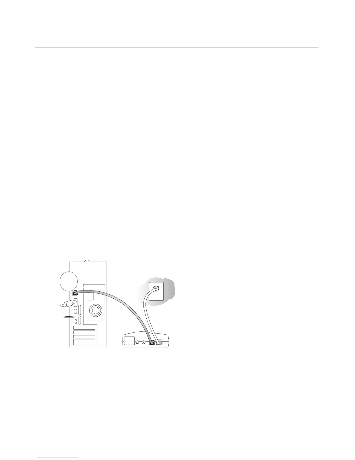
1. Connect the router to your network.
a. Turn off your computer and Cable or DSL Modem.
b. Disconnect the Ethernet cable (A) from your computer which connects to your cable or
DSL modem.
A
Cable or DSL modem
Figure 2-1: Disconnect the cable or DSL Modem
2-4 Connecting the Router to the Internet
Page 21

Reference Manual for the Model RP614 v2 Web Safe Router
c.
Connect the Ethernet cable from your cabl e or DSL mode m to the Internet port ( A) on the
Model RP614 v2.
Cable
or DSL modem
A
Cable/DSL Web Safe Router RP614
Figure 2-2: Connect the cable or DSL Modem to the router
d.
Connect the Ether net ca ble whi ch ca me wi th the rout er fr om a Loc al por t on the rout er (B)
to your computer.
Cable or
DSL modem
B
Cable/DSL Web Safe Router RP614
Figure 2-3: Connect the computers on your network to the router
Note: The RP614 v2 router incorporates Auto UplinkTM technology. Each Ethernet port
will automatically sense if the cable should have a normal connection or an uplink
connection. This f eature elimin ates the need to worr y about crossove r cables becaus e Auto
Uplink will make the right connection either type of cable.
e. Now, turn on your computer. If software usually logs you in to your Internet connection,
do not run that software or cancel it if it starts automatically.
Connecting the Router to the Internet 2-5
Page 22
Reference Manual for the Model RP614 v2 Web Safe Router
f.
Verify the following:
When your turn the router on, the power light goes on.
The test light turns on within a few seconds, and then goes off after approximately 10
seconds.
The router’s local lights are lit for any computers that are connected to it.
The router’s Internet light is lit, indicating a link has been established to the cable or DSL
modem.
2. Log in to the router.
Note: To connect to the router, your computer needs to be configured to obtain an IP address
automatically via DHCP. If you need instructions on how to do this, please refer to
Appendix C, “Preparing Your Network”.
a. Connect to the router by ty ping http://192.168.0.1 in the address filed of Internet Explorer
or Netscape® Navigator.
Figure 2-4: Log in to the router
b.
For security reasons, the router has its own user name and password. When prompted,
enter admin for the r outer use r name and password for the router password , both in lowe r
case letters.
Note: The router user name and password are not the same as any user name or password
you may use to log in to your Internet connection.
2-6 Connecting the Router to the Internet
Page 23
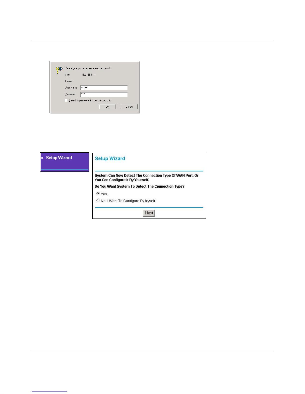
A login window shown below opens:
Figure 2-5: Login window
3. Connect to the Internet
Reference Manual for the Model RP614 v2 Web Safe Router
Figure 2-6: Setup Wizard
a.
You are now connected to the router. If you do not see the menu above, click the Setup
Wizard link on the upper left of the main menu.
b. Click Next and follow the steps in the Setup Wizard for inputting the configuration
parameters from your ISP to connect to the Internet.
Note: If you choose not to use the Setup Wizard, you can manually configure your
Internet connection settings by following the procedure “Manually Configuring Your
Internet Connection” on page 2-16.
Unless your ISP automatically assigns your configuration automatically via DHCP, you
will need the configuration parameters from your ISP as you recorded them previously in
“Worksheet to Record Your Internet Connection Information” on page 2-3.
Connecting the Router to the Internet 2-7
Page 24
Reference Manual for the Model RP614 v2 Web Safe Router
c.
When the router successfully detects an active Internet service, the router’s Internet LED
goes on. The Setup Wizard reports which connection type it discovered, and displays the
appropriate configuration menu. If the Setup Wizard finds no connection, you will be
prompted to check t he phys ical connec tion between yo ur ro uter and the cable or DSL line.
d. The Setup Wizard will report the type of connection it finds. The options are:
• Connections which require a login using protocols such as
PPPoE, AOL, PPTP, Telstra, or Bigpond broadband connections.
• Connections which use dynamic IP address assignment.
• Connections which use fixed IP address assignment.
The procedures for filling in the configuration menu for each type of connection follow
below.
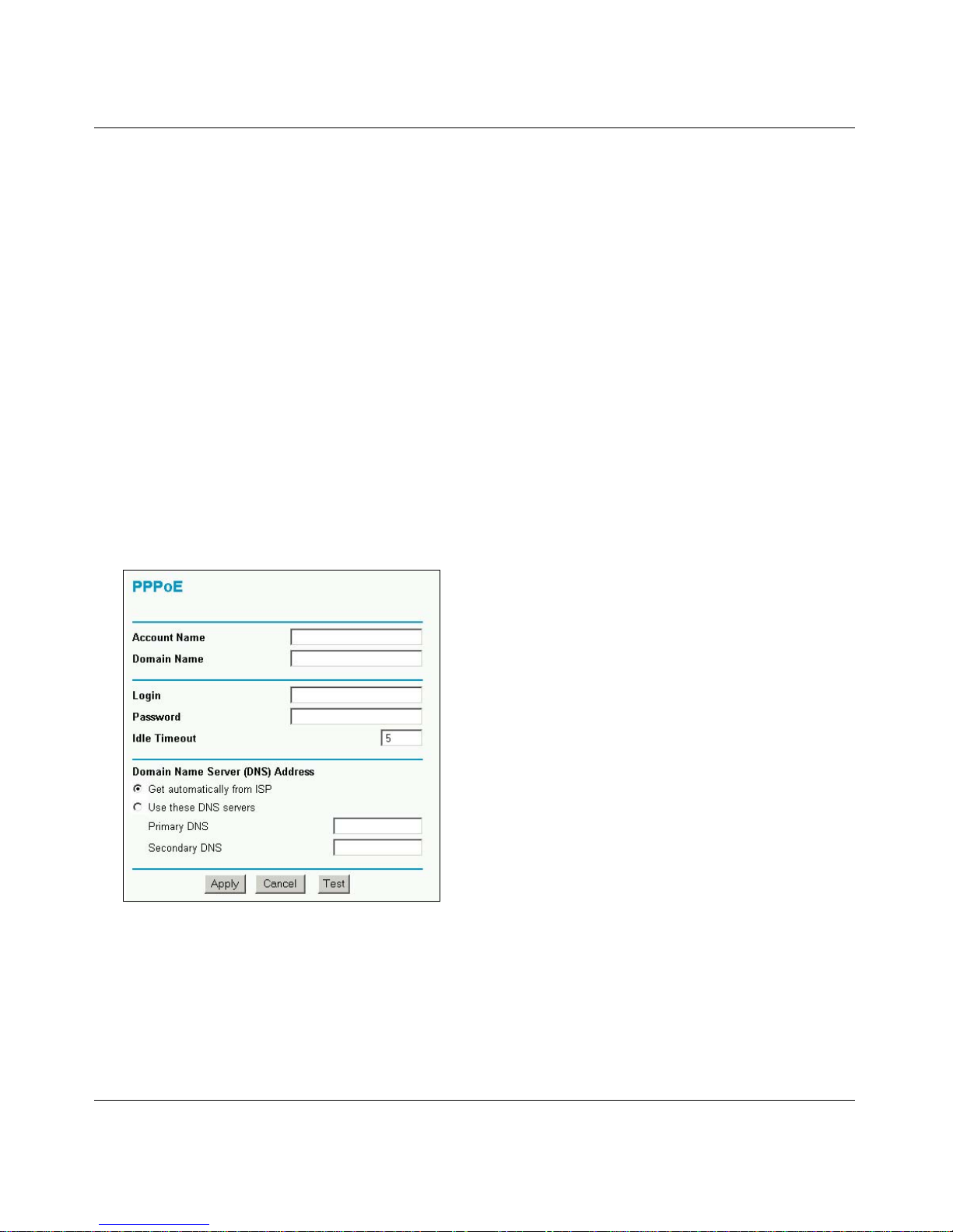
PPPoE Wizard-Detected Option
If the Setup Wizard discovers that your ISP uses PPPoE, you will see this menu:
Figure 2-7: Setup Wizard menu for PPPoE accounts
• Enter the Account Name, Domain Name, Login, and Pas sword as provide d by your ISP. These
fields are case sensitive. The router will try to discover the domain automatically if you leave
the Domain Name blank. Otherwise, you may need to enter it manually.
2-8 Connecting the Router to the Internet
Page 25

Reference Manual for the Model RP614 v2 Web Safe Router
• To change the login timeout, enter a new value in minutes. This determines how long the
router keeps the Internet connection active after there is no Internet activity from the LAN.
Entering a timeout value of zero means never log out.
Note: You no longer need to run the ISP’s login program on your PC in order to access the
Internet. When you start an Internet application, your router will automatically log you in.
• If you know that your ISP does not aut omat ic al ly t ra nsmi t DNS addresses to the router during
login, select “Use these DNS servers” and enter the IP address of your ISP’s Primary DNS
Server. If a Secondary DNS Server address is available, enter it also.
Note: If you enter DNS addresses, restart your computers so that these settings take effect.
• Click Apply to save your settings.
• Click Test to verify that your Internet connection works. If the NETGEAR website does not
appear within one minute, refer to Chapter 6, “Troubleshooting.”
AOL Wizard-Detected Options
Note: If you have an AOL account, any computer connected to the router must use the
AOL software to connect to th e In terne t thr ough the route r. If y ou have no t alr eady don e
so, install the AOL soft ware on your PC now. Be s ure to inst all t he AOL Home Net wor k
updates as well. AOL v8.0 software is included on the Model RP614 v2 Resource CD
which came with your Model RP614 v2.
• If the Setup Wizard discovers that AOL is your ISP, you will see a screen like the one below:
Figure 2-8: AOL detected
Connecting the Router to the Internet 2-9
Page 26
Reference Manual for the Model RP614 v2 Web Safe Router
s
• When the Setup Wizard detects an AOL DSL or Cable service, the RP614 v2 router
automatically pre-co nfigures itself to work with the AOL service.
Note: Services such as AOL which use L2TP tunneling will bypass the firewall feature
included with y our rout er. For addit ional ho me network securit y, install the PC- based Fr eedom
Firewall software application included on your Model RP614 v2 Resource CD.
• Click OK to continue. The fi lt er ing features of the Model RP614 v2 Web Safe Router ar e now
turned off. You will notice that the navigation menu now looks like the illustration below.
Figure 2-9: AOL supported features
AOL Supported Feature
2-10 Connecting the Router to the Internet
Page 27
Reference Manual for the Model RP614 v2 Web Safe Router
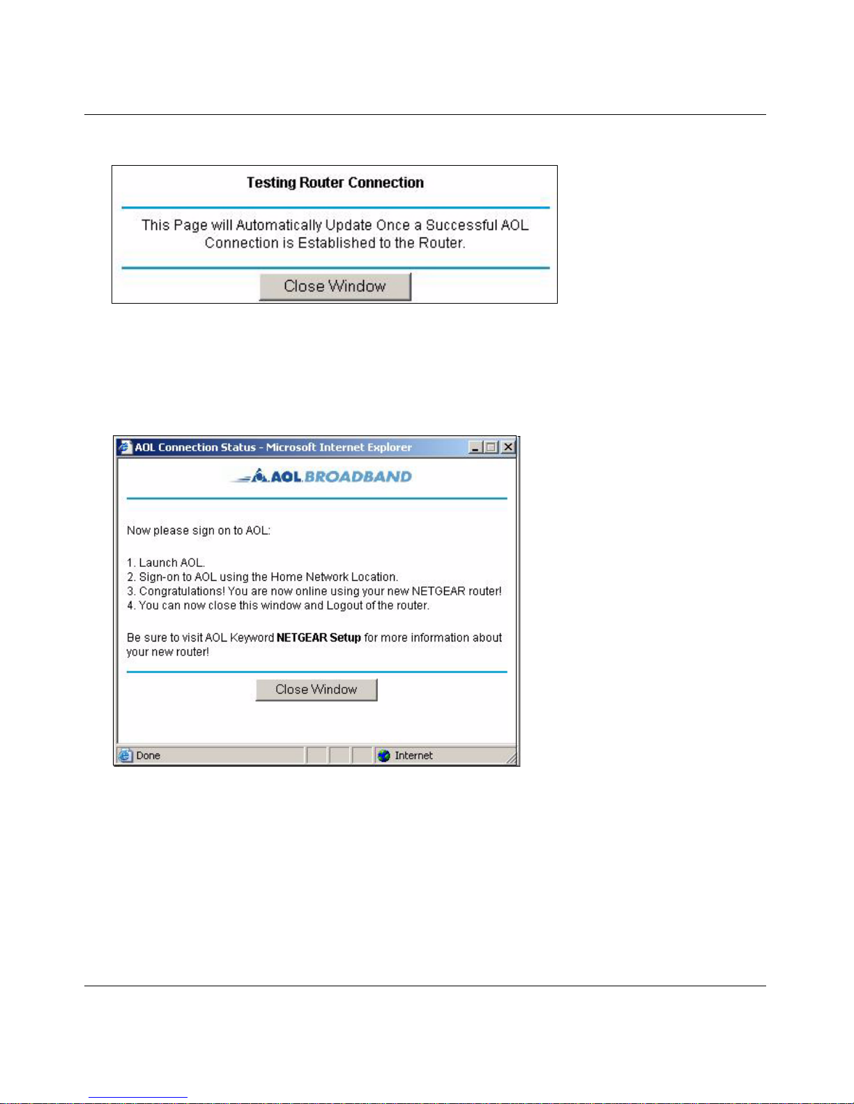
• Next, the router synchronized with the AOL network and displays the message below.
Figure 2-10: AOL network synchronization
• After the router finis hes t estin g the conn ection , the window up dates with t he AOL Conn ectio n
Established message below.
Figure 2-11: AOL connection established
Connecting the Router to the Internet 2-11
Page 28
Reference Manual for the Model RP614 v2 Web Safe Router
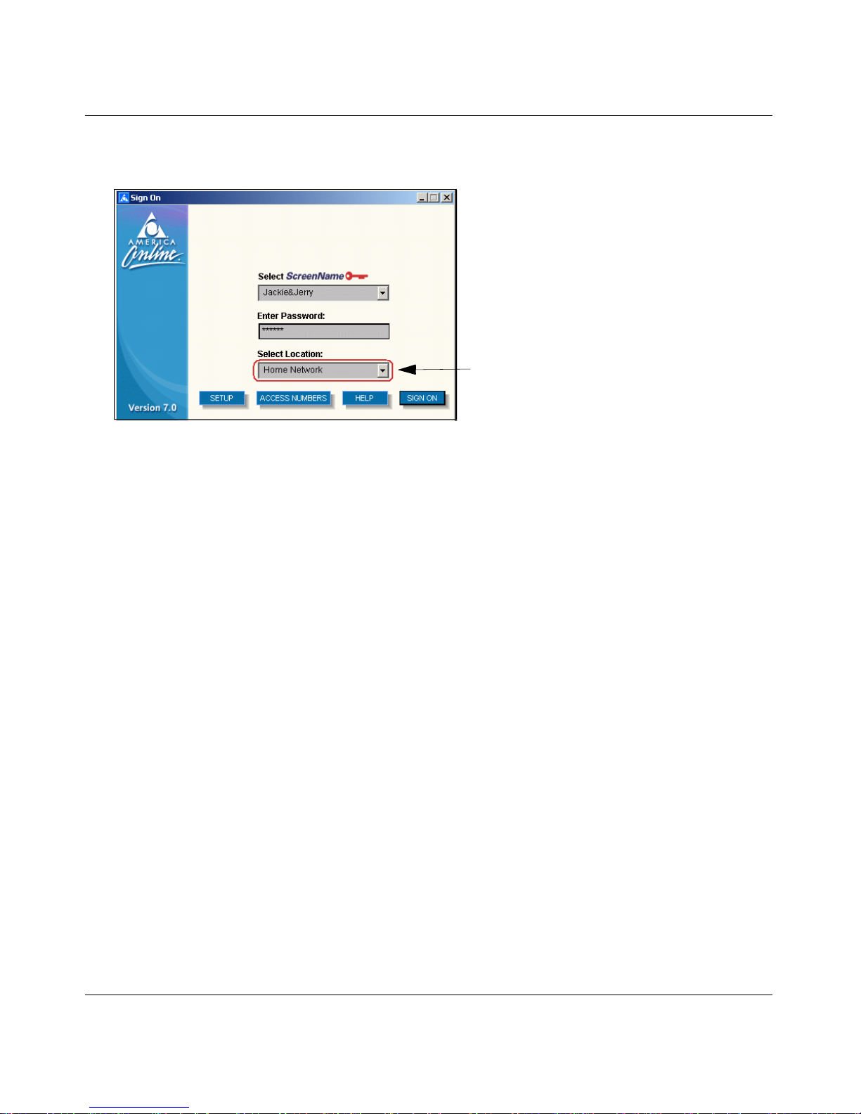
• From a computer connected to the router, sign on to AOL as illustrated below.
Select the correct
AOL location
Figure 2-12: AOL sign on screen
Note: Be sure that the AOL Ho me Networking updates are installed, and be sure to select the
correct AOL location: for AOL DSL, choose Home Networking; for AOL Cable, choose
Home - Cable.
• This completes the configurat ion of the RP614 v2 router for conne cting to your AOL ac count.
Now, all the computers on your network can share the AOL Internet connection through the
Model RP614 v2 We b Safe Router. To connect to the Internet, run the AOL software on a
computer, select Home Network as the location, sign on, and the router will share the
connection with others who are connected from different computers on the network.
2-12 Connecting the Router to the Internet
Page 29
Reference Manual for the Model RP614 v2 Web Safe Router
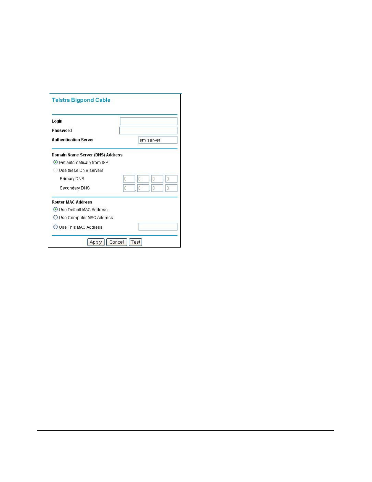
Telstra Bigpond Cable Wizard-Detected Option
If the Setup Wizard discovers Telstra Bigpond Cable is your ISP, you will see this menu:
Figure 2-13: Setup Wizard menu for Telstra Bigpond Cable accounts
• Enter your Login, Password and Authentication Server. These fields are case sensitive.
Note: You will no longer need to launch th e ISP’s login program on your PC in order to acce ss
the Interne t. When you start an Interne t application, your router will automatically log you in.
• The Domain Name Server (DNS) Address parameters may be necessary to access your ISP’s
services such as mail or news servers.
Note: If you enter DNS addresses, restart your computers so that these settings take effect.
• Router MAC Address:
This section determines the Ethernet MAC address that will be used by the router on the
Internet port. Some I SPs will register the Ethe rne t M AC add res s of the network interface car d
in your PC when your account is first opened. They will then only accept traffic from the
MAC address of that PC. This feature allows your router to masquerade as that PC.
T o change the MAC address, select “Use this Computer’s MAC address.” The router will then
capture and use the MAC address of the PC that you are now using. You must be using the one
PC that is allowed by the ISP. Or, select “Use this MAC address” and enter it.
Connecting the Router to the Internet 2-13
Page 30
Reference Manual for the Model RP614 v2 Web Safe Router
• Click Apply to save your settings.
• Click Test to test your Internet connection. If the NETGEAR website does not appear within
one minute, refer to Chapter 6, “Troubleshooting.
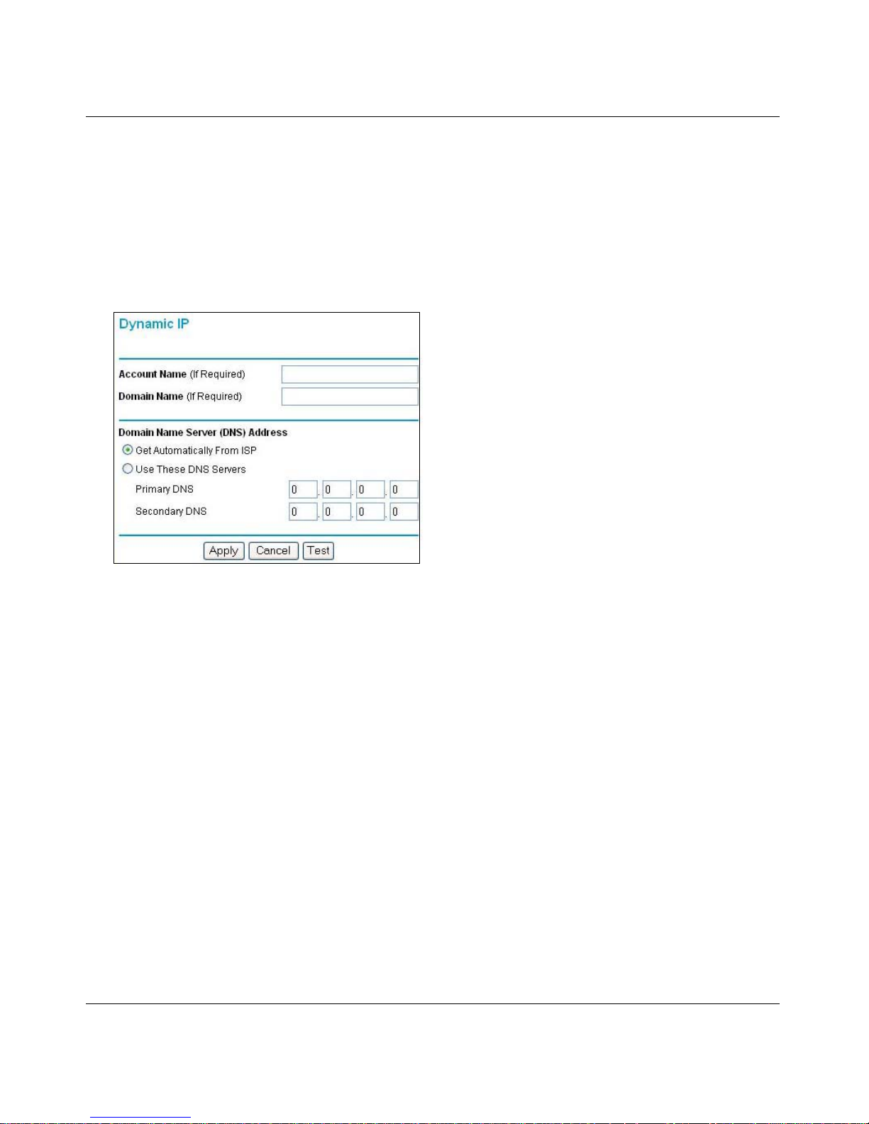
Dynamic IP Wizard-Detected Option
If the Setup Wizard discovers that your ISP us es Dyna mic I P assi gnment, you will see this menu:
Figure 2-14: Setup Wizard menu for Dynamic IP address accounts
• Enter your Account Name (may also be called Host Name) and Domain Name. These
parameters may b e necessa ry to acc ess your ISP’s servic es such a s mail or news serve rs. If yo u
leave the Domain Name fi eld blank, t he router tr y to disco ver the domai n. Otherwis e, you may
need to enter it manually.
• If you know that your ISP does not aut omat ic al ly t ra nsmi t DNS addresses to the router during
login, select Use these DNS servers and enter the IP address of your ISP’s Primary DNS
Server. If a Secondary DNS Server address is available, enter it also.
Note: If you enter DNS addresses, restart your computers so that these settings take effect.
• Click Apply to save your settings.
• Click Test to test your Internet connection. If the NETGEAR website does not appear within
one minute, refer to Chapter 6, “Troubleshooting.”
2-14 Connecting the Router to the Internet
Page 31

Reference Manual for the Model RP614 v2 Web Safe Router
Fixed IP Account Wizard-Detected Option
If the Setup Wizard discovers that your ISP uses Fixed IP assignment, you will see this menu:
Figure 2-15: Setup Wizard menu for Fixed IP address accounts
• Fixed IP is also called Static IP. Enter your assigned IP Address, Subnet Mask, and the IP
Address of your ISP’s gateway router. This information should have been provided to you by
your ISP. You will need the configuration parameters from your ISP you recorded in
“Worksheet to Record Your Internet Connection Information” on page 2-3.
• Enter the IP address of your ISP’s Primary and Secondary DNS Server addresses.
Note: Restart the computers on your network so that these settings take effect.
• Click Apply to save the settings.
• Click Test to test your Internet connection. If the NETGEAR website does not appear within
one minute, refer to Chapter 6, “Troubleshooting.”
Connecting the Router to the Internet 2-15
Page 32

Reference Manual for the Model RP614 v2 Web Safe Router
Manually Configuring Your Internet Connection
You can manual ly confi gure you r ro uter us ing the menu below, or you can allow the Setup Wiza rd
to determine your configuration as described in the previous section.
ISP Does Not Require Login
ISP Does Require Login
Figure 2-16: Browser-based configuration Basic Settings menus
2-16 Connecting the Router to the Internet
Page 33

Reference Manual for the Model RP614 v2 Web Safe Router
Procedure: Configuring the Internet Connection Manually
You can manually configure the router using the Basic Settings menu shown in Figure 2-16 using
these steps:
1. Click the Basic Settings link on the Setup menu.
2. If your Internet connection does not require a login, click No at the top of the Basic Settings
menu and fill in the settings according to the instructions below. If your Internet connection
does require a login, click Yes, and skip to step 3.
a. Enter your Account Name (may also be called Host Name) and Domain Name.
These parameters may be necessary to access your ISP’s services such as mail or news
servers.
b. Internet IP Address:
If your ISP has assigned you a permanent, fixed (static) IP address for your PC, select
“Use static IP address”. Enter the IP address that your ISP assigned. Also enter the
netmask and the Gateway IP addres s. The Gateway is the ISP’s router to whi ch your router
will connect.
c. Domain Name Server (DNS) Address:
If you know that your ISP does not automatically transmit DNS addresses to the router
during login, select “Use these DNS servers” and enter the IP address of your ISP’s
Primary DNS Server. If a Secondary DNS Server address is available, enter it also.
Note: If you enter an address here, restart the computers on your network so that these
settings take ef fec t.
d. Gateway’s MAC Address:
This section determines the Ethernet MAC address that will be used by the router on the
Internet port. Some I SPs will register the Ethernet MAC address of the network interface
card in your PC when your acc ount is f irst opened. The y will t hen only accept traf f ic from
the MAC address of that PC. This feature allows your router to masquerade as that PC by
“cloning” its MAC address.
To change the MAC address, select “Use this Computer’s MAC address.” The router will
then capture and use the MAC address of the PC that you are now using. You must be
using the one PC that is allowed by the ISP. Or, select “Use this MAC address” and enter
it.
e. Click Apply to save your settings.
Connecting the Router to the Internet 2-17
Page 34

Reference Manual for the Model RP614 v2 Web Safe Router
3.
If your Internet connect ion does require a logi n, fill in the settings according to the inst ructions
below. Select Yes if you normally must launch a lo gin program such as Enternet or WinPOET
in order to a ccess the Inte rnet.
Note: After you finish set ting up your ro uter, you will no longer nee d to launch the ISP’s login
program on your PC in order to access the Internet. When you start an Internet application,
your router will automatically log you in.
a. Select you Internet service provisory from the drop-down list.
Figure 2-17: Basic Settings ISP list
b.
The screen will change according to the ISP settings requirements of the ISP you select.
c. Fill in the parameters for your ISP according to the W izard-det ected procedur es startin g on
page 2-8.
d. Click Apply to save your settings.
2-18 Connecting the Router to the Internet
Page 35

Chapter 3
Content Filtering
This chapter describes how to use the content filtering features of the Model RP614 v2 Web Safe
Router to protect your network. These features can be found by clicking on the Content Filtering
heading in the Main Menu of the browser interface.
Content Filtering Overview
The Model RP614 v2 Web Safe Router provides you with Web content filtering options, plus
browsing activity reporting and instant alerts via e-mail. Parents and network administrators can
establish restricted access policies based on time-of-day, web addresses and web address
keywords. You can also block Internet access by applications and services, such as chat or games.
To configure these features of your router, click on the subheadings under the Content Filtering
heading in the Main Menu of the browser interface. The subheadings are described below:
Content Filtering 3-1
Page 36

Reference Manual for the Model RP614 v2 Web Safe Router
Blocking Access to Inte rnet Sites
The RP614 v2 router allows you to restrict access based on web addresses and web address
keywords. Up to 255 entries are supported in the Keyword list. The Block Sites menu is shown in
Figure 3-1 below:
Figure 3-1: Block Sites menu
To enable keyword blocking, select either “Per Schedule” or “Always”, then click Apply. If you
want to block by schedule, be sure that a time period is specified in the Schedule menu.
To add a keyword or domain, type it in the Keyword box, click Add Keyword, then click Apply.
To delete a keyword or domain, select it from the list, click Delete Keyword, then click Apply.
Keyword application examples:
• If the keyword "XXX" is specified, the URL <http://www.badstuff.com/xxx.html> is blocked.
3-2 Content Filtering
Page 37

Reference Manual for the Model RP614 v2 Web Safe Router
• If the keyword “.com” is specified, only websites with other domain suffixes (such as .edu or
.gov) can be viewed.
• If you wish to block all Inte rnet br owsing access during a sc hedule d peri od, ente r the k eywor d
“.” and set the schedule in the Schedule menu.
To specify a Trusted User, enter that PC’s IP address in the Trusted User box and click Apply.
You may specify one Trusted User, which is a PC that will be exempt from blocking and
logging. Since the Trusted User will be identified by an IP address, you should configure that
PC with a fixed IP address.
Blocking Access to Internet Services
The RP614 v2 router allows you to block the use of certain Internet services by PCs on your
network. This is called services blocking or port filtering. The Block Services menu is shown
below:
Figure 3-2: Block Services menu
Services are functions performed by server computers at the request of client computers. For
example, Web servers serve web pages, time servers serve time and date information, and game
hosts serve data about o ther play ers’ moves. When a comput er on your network se nds a reque st for
service to a ser ver comput er on the Internet, the requested service is iden ti fi ed by a service or port
number. This number appears as the destination port number in the transmitted IP packets. For
example, a packet that is sent with destination port number 80 is an HTTP (Web server) request.
To enable service bloc ki ng, sel ec t ei ther Per Schedule or Always, then clic k Apply. If you want to
block by schedule, be sure that a time period is specified in the Schedule menu.
Content Filtering 3-3
Page 38

Reference Manual for the Model RP614 v2 Web Safe Router
To specify a ser vi ce for bl ock ing, click Add. The Add Serv ic es me nu wi ll appear, as sh own b elow:
Figure 3-3: Add Services menu
From the Service Type list, select the application or service to be allowed or blocked. The list
already displays several common services, but you are not limited to these choices. To add any
additional services or applications that do not already appear, select User Defined.
Configuring a User Defined Service
To define a service, first you must determine which port number or range of numbers is used by
the application. The service numbers for many common protocols are defined by the Internet
Engineering Task Force (IETF) and published in RFC1700, “Assigned Numbers.” Service
numbers for oth er appli cations are typi cally ch osen from t he ra nge 1024 to 65535 by th e auth ors of
the application. This information can usually be determined by contacting the publisher of the
application or from user groups of newsgroups.
Enter the S tarting Port and En ding Por t numbers. If the a pplicat ion uses a single port n umber , ent er
that number in both boxes.
If you know that the ap plicati on uses either TCP or UDP, select the appropria te protoco l. If you are
not sure, select Both.
3-4 Content Filtering
Page 39

Reference Manual for the Model RP614 v2 Web Safe Router
Configuring Services Blocking by IP Address Range
Under “Filter Services For”, you can block the specified service for a single PC, a range of PCs
(having consecutive IP addresses), or all PCs on your network.
Scheduling Whe n Bl ocking Will Be Enforced
The RP614 v2 router a llows you to s pecif y when bl ockin g will be enf orced. The Schedul e menu is
shown below:
Figure 3-4: Schedule menu
• Use this schedule for blocking content. Check this box if you wish to enable a schedule for
Content Filtering. Click Apply.
• Days to Block. Select days to block by checking the appropriate boxes. Select Everyday to
check the boxes for all days. Click Apply.
• Time of Day to Block. Select a start and end time in 23:59 format. Select All day for 24 hour
blocking. Click Apply.
Be sure to select your Time Zone in the E-Mail menu.
Content Filtering 3-5
Page 40

Reference Manual for the Model RP614 v2 Web Safe Router
Stateful Packet Inspection (SPI), Java, ActiveX, and Cookies
Blocking Options
The WAN Setup options let you enable SPI and blocking of Java, ActiveX, and Cookies. These
options are discussed below.
Using SPI
Stateful inspection technology tracks each packet traversing the router and makes sure that
they are legitimate. A stateful inspection router also monitors the state of the connection
and compiles the information in a state table ensuring that the source and destination of
each packet is valid. By default, SPI is enabled.
You access the SPI and the Java, ActiveX, and Cookies blocking options from the WAN Setup
menu, as shown below.
Figure 3-5: WAN Setup menu.
3-6 Content Filtering
Page 41

Reference Manual for the Model RP614 v2 Web Safe Router
Using Java, ActiveX, and cookies Filtering.
What are these items and what can I do about them?
• ActiveX and Java programs can be embedded in websites, and will be executed by your
computer. These programs may sometimes include malicious content.
• Cookies are small files that a website can store on your computer to track your activity.
Some cookies can be helpful, but some may compromise your privacy.
To block these items, follow these steps :
1. Click WAN Setup link on the Advanced section of the main menu.
2. Type the IP address for that server. To remove the default DMZ server, replace the IP address
numbers with all zeros.
3. To block ActiveX, Java, Cooki es, or Web Proxy functions for all In terne t sites, cli ck the check
box next to the function and then click Apply.
Viewing Logs of Web Access or Attempted Web Acces s
The log is a detailed record of what websites you have accessed or attempted to access. Up to 128
entries are stored in the log. Log entries will only appear when keyword blocking is enabled, and
no log entries will be made for the Trusted User. An example is shown below:
Figure 3-6: Logs menu
Content Filtering 3-7
Page 42

Reference Manual for the Model RP614 v2 Web Safe Router
Log entrie s are described in Table 3-1
Table 3-1. Log entry descriptions
Field Description
Number The index number of the content filter log entries. 128 entries
are available numbered from 0 to 127. The log will keep the
record of the latest 128 entries.
Date and Time The date and time the log entry was recorded.
Source IP The IP address of the initiating device for this log entry.
Action This field displays whether the access was blocked or allowed.
The name or IP address of the website or newsgroup visited or
attempted to access.
Log action buttons are described in Table 3-2
Table 3-2. Log action buttons
Field Description
Refresh Click this button to refresh the log screen.
Clear Log Click this button to clear the log entries.
Send Log Click this button to email the log immediately.
3-8 Content Filtering
Page 43

Reference Manual for the Model RP614 v2 Web Safe Router
Configuring E-Mail Alert a nd Web Acces s Log Notifications
In order to receive logs and al erts by email, you must provide your email informati on in the E-Mail
menu, shown below:
Figure 3-7: Email menu
• Turn e-mail notification on
Check this box if you wish to receive e-mail logs and alerts from the router.
• Your outgoing mail server
Enter the name of your ISP’s outgoing (SMTP) mail server (such as mail.myISP.com). You
may be able to find this info rmat ion in the configuration menu of your e- mai l pro gram. If you
leave this box blank, log and alert messages will not be sent via e-mail.
Content Filtering 3-9
Page 44

Reference Manual for the Model RP614 v2 Web Safe Router
• Send to this e-mail address
Enter the e-mail address to whic h logs and alerts are sent . This e-mail address wi ll also be used
as the From address. If you leave this box blank, log and alert messages will not be sent via
e-mail.
You can specify that logs are automatically sent to the specified e-mail address with these options:
• Send alert immediately
Check this box if you would like immediate notification of attempted access to a blocked site.
• Send logs according to this schedule
Specifies how often to send the logs: Hourly, Daily, Weekly, or When Full.
– Day for sending log
Specifies which day of the week to send the log. Relevant when the log is sent weekly or
daily.
– Time for sending log
Specifies the time of day to send the log. Relevant when the log is sent daily or weekly.
If the Weekly, Daily or Hourly option is selected and the log fills up before the specified
period, th e log is autom atically e- mailed to the specified e-mail address. After the log is sent,
the log is cleared from the router’s memory. If the router cannot e-mail the log file, the log
buffer may fill up. In this case, the router overwrites the log and discards its contents.
The RP614 v2 router uses the Network Time Protocol (NTP) to obtain the current time and date
from one of several Ne twork Time Servers on the Internet. In order to localize the time for your
log entries, you must specify your Time Zone:
•Time Zone
Select your local time zone. This setting will be used for the blocking schedule and for
time-stamping log entr ies.
• Daylight Savings Time
Check this box if your time zone is currently under daylight savings time.
3-10 Content Filtering
Page 45

Chapter 4
Maintenance
This chapter describes how to use the maintenance features of your Model RP614 v2 Web Safe
Router. These featu res can be f ound by clicking on the Mainte nanc e heading in the Main Menu of
the browser interface.
Viewing Router Status Information
The Router Status menu provides a limited amount of status and usage information. From the
Main Menu of the browser interface, click on Maintenance, then select System Status to view the
System Status screen, shown below.
Figure 4-1. Router Status screen
Maintenance 4-1
Page 46

Reference Manual for the Model RP614 v2 Web Safe Router
This screen shows the following parameters:
Table 4-1. Menu 3.2 - Router Status Fields
Field Description
Account Name This field displays the Host Name assigned to the router.
Firmware Version This field displays the router firmware version.
Internet Port These parameters apply to the Internet (WAN) port of the router.
MAC Address This field displays the Media Access Control address being used by the
Internet (WAN) port of the router.
IP Address This fie ld d is pla ys the IP add res s be ing us ed b y th e Inte rne t (WAN) port
of the router. If no address is shown, the router cannot connect to the
Internet.
IP Subnet Mask This field displays the IP Subnet Mask bein g used by the Inter net (W AN)
port of the router.
DHCP If set to None, the router is configured to use a fixed IP address on the
WAN.
If set to Client, the router is configured to obtain an IP address dynamically from the ISP.
LAN Port These parameters apply to the Local (WAN) port of the router.
MAC Address This field displays the Media Access Control address being used by the
LAN port of the router.
IP Address This field displays the IP address being used by the Local (LAN) port of
the router. The default is 192.168.0.1
IP Subnet Mask This field displays the IP Subnet Mask being used by the Local (LAN)
port of the router. The default is 255.255.255.0
DHCP Identifies if the router’s built-in DHCP server is active for the LAN
attached devices.
4-2 Maintenance
Page 47

Reference Manual for the Model RP614 v2 Web Safe Router
Click on the “Connection Status” button to display the connection status, as shown below.
Figure 4-2. Connection Status screen
This screen shows the following statistics: .
Table 4-1. Connection Status Fields
Field Description
IP Address The WAN (Internet) IP Address assigned to the router.
Subnet Mask The WAN (Internet) Subnet Mask assigned to the router.
Default Gateway The WAN (Internet) default gateway the router communicates with.
DHCP Server The WAN (Internet) DHCP Server the router communicates with.
DNS Server The WAN (Internet) DNS Server for the router.
Lease Obtained When the DHCP lease started.
Lease Expires When the DHCP lease will expire.
Maintenance 4-3
Page 48

Reference Manual for the Model RP614 v2 Web Safe Router
Log action buttons are described in Table 4-2
Table 4-2. Connection Status action buttons
Field Description
Release Click the Release button to release the DHCP lease.
Renew Click the Renew button to renew the DHCP lease.
Close Window
Click this button to close the window.
Click on the “Show Statistics” button to display router usage statistics, as shown below.
Figure 4-3. Router Statistics screen
This screen shows the following statistics: .
Table 4- 1. Router Statistics Fields
Field Description
Port The statistics for the WAN (Internet) and LAN (local) ports. For each port, the screen
displays:
Status The link status of the port.
TxPkts The number of packets transmitted on this port since reset or manual clear.
RxPkts The number of packets received on this port since reset or manual clear.
Collisions The number of collisions on this port since reset or manual clear.
Tx B/s The current transmission (outbound) bandwidth used on the WAN and LAN ports.
Rx B/s The current reception (inbound) bandwidth used on the WAN and LAN ports.
4-4 Maintenance
Page 49

Reference Manual for the Model RP614 v2 Web Safe Router
Table 4-1. Router Statistics Fields (continued)
Field Description
Up Time The time elapsed since this port acquired the link.
Poll Interval Spe ci fie s the inte rval s at which the statistics are up dat ed in this window. Click on St o p
to freeze the display.
Viewing a List of Attached Devices
The Attached Devices menu contains a ta ble of al l IP devices that the router has discovered on the
local network. From the Main Menu of the browser interface, under the Maintenance heading,
select Attached Devices to view the table, shown below.
Figure 4-4. Attached Devices menu
For each device, the table shows the IP address, NetBIOS Host Name (if available), and Ethernet
MAC address. Note that if the router is reboot ed, the table data is lost until the rou t er rediscovers
the devices. To force the router to look for attached devices, click the Refresh button.
Upgrading the Router Software
The routing software of t he RP614 v2 router is stored in FLASH memory, and can be upgr ade d as
new software is release d by NETGEAR. Upgr ade fil es can be downloaded from Netg ear's web site.
If the upgrade file is compressed (.ZIP file), you must first extract the binary (.BIN) file before
sending it to the router. The upgrade file can be sent to the router using your browser.
Note: The Web browser used to upload new firmware into the RP614 v2 router must support
HTTP uploads. NETGEAR recommends using Micro soft Interne t Explorer or Net scape Navigator
3.0 or above.
Maintenance 4-5
Page 50

Reference Manual for the Model RP614 v2 Web Safe Router
From the Main Menu of the browser interface, under the Maintenance heading, select the Router
Upgrade heading to display the menu shown below.
Figure 4-5. Router Upgrade menu
To upload new firmware:
1. Download and unzip the new software file fro m NETGEAR.
2. In the Router Upgra de men u, click the Browse button a nd b rows e t o t he l oc ati on of the binary
(.BIN) upgrade file
3. Click Upload.
Note: When uploading software to the RP614 v2 router, it is important not to interrupt the
Web browser by closing the window, clicking a link, or loading a new page. If the browser is
interrupted, it may corrupt the software. When the upload is complete, your router will
automatically restart. The upgrade process will typically take about one minute.
In some cases, you may need to reconfigure the router after upgrading.
Configuration File Management
The configuration settings of the RP614 v2 router are stored within the router in a configuration
file. This file can be saved (backed up) to a user’s PC, retrieved (restored) from the user’s PC, or
cleared to factory default settings.
4-6 Maintenance
Page 51

Reference Manual for the Model RP614 v2 Web Safe Router
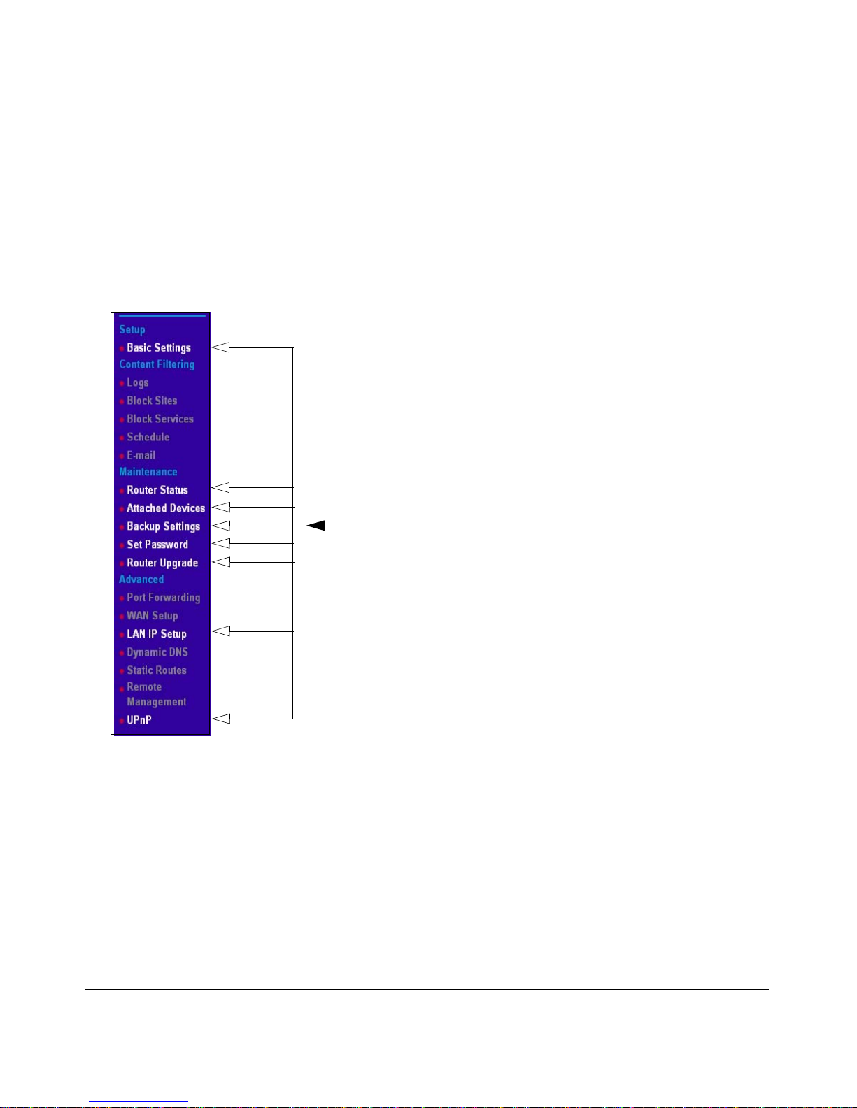
From the Main Menu of the browser int er fa ce, und er the Main te nance heading, select the Setti ngs
Backup heading to bring up the menu shown below.
Figure 4-6. Settings Backup menu
Three options are available, and are described in the following sections.
Restoring and Backing Up the Configuration
The Restore and Backup opti ons in the Settin gs Backup menu al lo w you to save and re trie ve a file
containing your router’s configuration settings.
To save your settings, select the Backup tab. Click the Backup button. Your browser will extract
the configuration file from the router and will prompt you for a location on your PC to store the
file. You can give the file a meaningful name at this time, such as pacbell.cfg.
To restore your s etti ngs f rom a s aved c onfig urati on fi le, e nte r the ful l pat h to the f ile on your PC or
click the Browse button to brows e to the file. When you have located it, clic k the Restore butt on to
send the file to the router. The router will then reboot automatically.
Maintenance 4-7
Page 52

Reference Manual for the Model RP614 v2 Web Safe Router
Erasing the Configuration
It is sometimes desirable to restore the router to a known blank condition. This can be done by
using the Erase function, which will restore all factory settings. After an erase, the router's
password will be password, th e LAN IP address will be 192.168.0.1, and th e router's DHCP client
will be enabled.
To erase the configuration, click the Erase button.
To restore the factory default configuration settings without knowing the login password or IP
address, you must use the Default Reset button on the rear panel of the router. See “Restoring the
Default Configuration and Password” on page 6-7.
Changing the Configuration Password
The default password for the router’s Web Configuration Manager is password. Netgear
recommends that you change this password to a more secure password.
From the Main Menu of the browser interface, under the Maintenance heading, select Set
Password to bring up the menu shown below.
Figure 4-7. Set Password menu
T o change the password, first enter the old password, and then enter the new password twice. Click
Apply.
4-8 Maintenance
Page 53

Chapter 5
Advanced Configu r ation of the Router
This chapter desc ri bes how to configure the advanced features of your Model RP614 v2 Web Safe
Router. These featu res can be found under the Advance d heading i n the Main Menu of the br owser
interface.
Configuring for Port Forwarding to Local Servers
Although the router ca uses your entire local network to appear as a single machine to the I n te rne t,
you can make a local server (fo r example, a web serve r or game server) visible and available to the
Internet. This is done using the Port Forwarding menu. From the Main Menu of the browser
interface, under Advanced, click on Port Forwarding to view the port forwarding menu, shown
below.
Figure 5-1: Port Forwarding Menu
Advanced Configuration of the Router 5-1
Page 54

Reference Manual for the Model RP614 v2 Web Safe Router
.
Note: If you are unfamiliar with networking and routing, refer to Appendix B,
“Networks, Routing, and Firewall Basics,” to become more familiar with the terms and
procedures used in this manual.
Use the Port Forwar ding menu to conf igure the router to f orward incomi ng prot ocols to c ompute rs
on your local network. In addition to servers for specific applications, you can also specify a
Default DMZ Server to which all other incoming protocols are forwarded. The DMZ Server is
configured in the Security Menu.
Before starting, yo u'l l ne ed t o det er m ine whic h type of service, applicati on or g ame you 'l l pr ovi de
and the IP address of the computer that will provide each service. Be sure the computer’s IP
address never changes. To configure port forwarding to a local server:
1. From the Service & Game box, select the service or game that you will host on your network.
If the service does not a ppear in the list, refer to the followi ng section, “Adding a Custom
Service”.
2. Enter the IP address of the local server in the corresponding Server IP Address box.
3. Click the Add button.
Adding a Custom Service
To define a service, game or application that does not appear in the Services & Games list, you
must determine what port numbers are used by the service. For this information, you may need to
contact the manufacturer of the program that you wish to use. When you have the port number
informati on, follow these steps:
1. Click the Add Custom Service button.
2. Enter the first port num ber in an unused Start Port box.
3. To forward only one port, enter it again in the End Port box. To specify a range of ports, enter
the last port to be forwarded in the End Port box.
4. Enter the IP address of the local server in the corresponding Server IP Address box.
5. Type a name for the service.
6. Click Apply at the bottom of the menu.
5-2 Advanced Configuration of the Router
Page 55

Reference Manual for the Model RP614 v2 Web Safe Router
Editing or Deleting a Port Forwarding Entry
To edit or delete a Port Forwarding entry, follow these steps.
1. In the table, select the button next to the service name.
2. Click Edit or Delete.
Local Web and FTP Server Example
If a local PC with a priva te IP addres s of 192 .168.0.33 a cts as a Web and FTP server, conf igure the
Ports menu to forward HTTP (port 80) and FTP (port 21) to local address 192.168.0.33
In order for a remote user to access this server from the Internet, the remote user must know the IP
address that has be en assigned by your ISP. If this address is 172.16 .1.23 , for example, an Internet
user can access your Web server by directing the browser to http://172.16.1.23. The assigned IP
address can be found in the Maintenance Status Menu, where it is shown as the WAN IP Address.
Some considerations for this application are:
• If your account’s IP address is assigned dynamically by your ISP, the IP address may change
periodically as the DHCP lease expires.
• If the IP address of the local PC is assign ed by DHCP, it may change when the PC is rebooted.
To avoid this, you can manually configure the PC to use a fixed address.
• Local PCs must access the local ser ver using th e PCs’ local LAN addr ess (192.168 .0.33 in this
example). Attempts b y local PCs to access the server using the external IP address
(172.16.1.23 in this example) will fail.
Multiple Computers for Half Life, KALI or Quake III Example
To set up an additional computer to play Half Life, KALI or Quake III:
1. Click the button of an unused port in the table.
2. Select the game again from the Services/Games list.
3. Change the beginning port number in the Start Port box.
For these games, use the supplied number in the default listing and add +1 for each additional
computer. For example, if you've already configured one computer to play Hexen II (using
port 26900), the second computer's port number would be 26901, and the third computer
would be 26902.
Advanced Configuration of the Router 5-3
Page 56

Reference Manual for the Model RP614 v2 Web Safe Router
4.
Type the same port number in the End Port box that you typed in the Start Port box.
5. Type the IP address of the additional computer in the Server IP Address box.
6. Click Apply.
Some online games and videoconferencing applications are incompatible with NAT. The RP614
v2 router is programmed to recognize some of these applications and to work properly with them,
but there are other app licati ons th at may not funct ion we ll. I n some c ases, one l ocal P C ca n run the
application properly if that PC’s IP address is entered as the default in the PORTS Menu. If one
local PC acts as a game or videoconferencing host, enter its IP address as the default.
Configuring the WAN Setup Options
The WAN Setup options let you configure a DMZ server, change the MTU size and enable the
router to respond to a Ping on the WAN port. These options are discussed below.
Setting Up a Default DMZ Server
The default DMZ server feature is helpful when using some online games and videoconferencing
applications th at are in compatible with NAT . The ro uter is progr ammed to rec ognize some o f these
applications a nd to work p roperl y wit h them, but t here are oth er ap plica tions t hat may no t fun ction
well. In some cases, one local PC can run the a pplicat ion proper ly if that PC’s IP addr ess is ent ered
as the default DMZ server.
Note: DMZ servers pose a security risk. A computer designated as the default DMZ
server loses much of the protection of the firewall, and is exposed to exploits from the
Internet. If compromised, the DMZ server can be used to attack your network.
Incoming traffic from the Internet is normally discarded by the router unless the traffic is a
response to one of your local computers or a service that you have configured in the Ports menu.
Instead of discar ding this t raf fic, you ca n have it for warded to one computer on you r network. Thi s
computer is called the Default DMZ Server.
5-4 Advanced Configuration of the Router
Page 57

Reference Manual for the Model RP614 v2 Web Safe Router
The WAN Setup menu, shown below lets you configure a Default DMZ Server.
Figure 5-2: WAN Setup menu.
To assign a computer or server to be a Default DMZ server, follow these steps:
1. Click WAN Setup link on the Advanced section of the main menu.
2. Type the IP address for that server. To remove the default DMZ server, replace the IP address
numbers with all zeros.
3. Click Apply.
Respond to Ping on Internet WAN Port
If you want the router to respond to a 'ping' from the Internet, click the ‘Respond to Ping on
Internet WAN Port’ check box. This should only be used as a diagnostic tool, since it allows your
router to be discovered. Don't check this box unless you have a specific reason to do so.
Advanced Configuration of the Router 5-5
Page 58

Reference Manual for the Model RP614 v2 Web Safe Router
Setting the MTU Size
The default MTU siz e i s usua ll y fine. The normal MTU (Maxi mum Transmit Unit) va lue for most
Ethernet networks is 15 00 Bytes. Fo r so me ISPs, par ticu larl y some usi ng PPPoE, you may n eed to
reduce the MTU. This should not be done unless you are sure it is necessary by your ISP.
Any packets sent through the router that are larger than the configured MTU size will be
repackaged into smaller packets to meet the MTU requirement. To change the MTU size :
1. Under MTU Size, enter a new size between 64 and 1500.
2. Click Apply to save the new configuration.
Using the LAN IP Setup Options
The second feature category under the Advanced heading is LAN IP Setup. This menu allows
configuration of LAN IP services such as DHCP and RIP. From the Main Menu of the browser
interface, under Advanced, click on LAN IP Setup to view the LAN IP Setup menu, shown below.
Figure 5-3: LAN IP Setup Menu
5-6 Advanced Configuration of the Router
Page 59

Reference Manual for the Model RP614 v2 Web Safe Router
Configuring LAN TCP/IP Setup Parameters
The router is shipped preconfigured to use private IP addresses on the LAN side, and to act.as a
DHCP server. The router’s default LAN IP configuration is:
• LAN IP addresses—192.168.0.1
• Subnet mask—255.255.255.0
These addresses are part of the IETF-desi gnated private addre ss r an ge f or use in private net works ,
and should be suit able i n most a pplic ations . If yo ur net work has a r equir ement t o use a dif fe rent I P
addressing scheme, you can make those changes in this menu.
The LAN IP parameters a re:
• IP Address
This is the LAN IP address of the router.
• IP Subnet Mask
This is the LAN Sub net Mask of the router. Combined with the IP addres s, the I P Subnet Mask
allows a device to know which other addresses are local to it, and which must be reached
through a gateway or router.
• RIP Direction
RIP (Router Inform at ion Prot ocol) allows a router to exc hange routing information wi th other
routers. The RIP Direction selection controls how the router sends and receives RIP packets.
Both is the default.
— When set to Both or Out Only, the router will broadcast its routing table periodically.
— When set to Both or I n Only, it will incorporate the RIP information that it receives.
— When set to None, it will not send any RIP packets and will ignore any RIP packets
received.
• RIP Version
This controls the fo rm at and the broadcasting method of t he RIP packets that the ro ute r sends.
(It recognizes both formats when receiving.) By default, this is set for RIP-1.
— RIP-1 is universall y sup por ted. RIP-1 is probably adequate fo r most networks, unless you
have an unusual network setup.
— RIP-2 carries more information. RIP-2B uses subnet broadcasting.
Advanced Configuration of the Router 5-7
Page 60

Reference Manual for the Model RP614 v2 Web Safe Router
Note: If you change the LAN IP address of the router while connected through the
browser, you will be disconnected. You must then open a new connection to the new IP
address and log in again.
Using the Router as a DHCP server
By default, the router will function as a DHCP (Dynamic Host Configuration Protocol) server,
allowing it to assign IP, DNS server, and default gateway addresses to all computers connected to
the router's LAN. The assigned default gateway address is the LAN address o f the router. IP
addresses will be assigned to the attached PCs from a pool of addresses specified in this menu.
Each pool address is tested before it is assigned to avoid duplicate addresses on the LAN.
For most applicati ons, the def ault DHCP and TCP/I P settin gs of th e router a re satisfa ctory. See “IP
Configuration by DHCP” on page B-11 for an explanat ion of DHCP and informati on about how to
assign IP addresses for your network.
If another device on your network will be the DHCP server, or if you will manually configure the
network settings of all of your computers, clear the ‘Use router as DHCP server’ check box.
Otherwise, leave it checked.
Specify the pool of IP addresses to be assigned by setting the Starting IP Address and Ending IP
Address. These addresses should be part of the same IP address subnet as the router’s LAN IP
address. Using the default addressi ng s cheme, you should define a range between 192.168.0.2 and
192.168.0.253, although you may wish to save part of the range for devices with fixed addresses.
The router will deliver the following parameters to any LAN device that requests DHCP:
• An IP Address from the range you have defined
• Subnet Mask
• Gateway IP Address (the router’s LAN IP address)
• Primary DNS Server (if you entered a Primary DNS address in the Basic Settings menu;
otherwise, the router’s LAN IP address)
• Secondary DNS Server (if you entered a Secondary DNS address in the Basic Settings menu
5-8 Advanced Configuration of the Router
Page 61

Reference Manual for the Model RP614 v2 Web Safe Router
Using Address Reservation
When you specify a reserved IP address for a PC on the LAN, that PC will always receive the
same IP address each time it access the router’s DHCP server. Reserved IP addresses should be
assigned to servers that require permanent IP settings.
To reserve an IP address:
1. Click the Add button.
2. In the IP Address box, type the IP address to assign to the PC or server.
(choose an IP address from the router’s LAN subnet, such as 192.168.0.X)
3. Type the MAC Address of the PC or server.
(Tip: If the PC is already present on your network, you can copy its MAC address from the
Attached Devices menu and paste it here.)
4. Click Apply to enter the reserved address into the table.
Note: The reserved address will not be assigned until the next time the PC contacts the router's
DHCP server. Reboot the PC or access its IP configuration and force a DHCP release and renew.
To edit or delete a reserved address entry:
1. Click the button next to the reserved address you want to edit or delete.
2. Click Edit or Delete.
Using a Dynamic DNS Service
If your network has a permanently assigned IP address, you can register a domain name and have
that name linked with your IP address by public Domain Name Servers (DNS). However, if your
Internet account uses a dynamically assigned IP address, you will not know in advance what your
IP address will be, and the address can change frequently. In this case, you can use a commercial
dynamic DNS service, who will allow you to register your domain to their IP address, and will
forward traffic directed at your domain to your frequently-changing IP address.
Note: If your ISP assigns a private WAN IP address (such as 192.168.x.x or 10.x.x.x),
the dynamic DNS service will not work because private addresses will not be routed on
the Internet.
Advanced Configuration of the Router 5-9
Page 62

Reference Manual for the Model RP614 v2 Web Safe Router
The router contains a client that can connect to many popular dynamic DNS services. You can
select one of these services and obtain an account with them. Then, whenever your ISP-assigned
IP address changes, your router will automatically contact your dynamic DNS service provider,
log in to your account, and register your new IP address.
From the Main Menu of the browser interface, under Advanced, click on Dynamic DNS. To
configure Dynamic DNS:
1. Register for an account with one of the dynamic DNS service providers whose names appear
in the ‘Select Service Provider’ box. For example, for dyndns.org, go to www.dyndns.org.
2. Select the Use a dynamic DNS service check box.
3. Select the name of your dynamic DNS Service Provider.
4. Type the Host Name (or domain name) that your dynamic DNS service provider gave you.
5. Type the User Name for your dynamic DNS account.
6. Type the Password (or key) for your dynamic DNS account.
7. If your dynamic DNS provider allows the use of wildcards in resolving your URL, you may
select the Use wildcards check box to activate this feature.
For example, the wildcard feature will cause *.yourhost.dyndns.org to be aliased to the same
IP address as yourhost.dyndns.org
8. Click Apply to save your configuration.
Configuring Static Routes
Static Routes provide additional routing information to your router. Under normal circumstances,
the router has adequate routing information after it has been configured for Internet access, and
you do not need to configure additional static routes. You must configure static routes only for
unusual cases such as multiple routers or multiple IP subnets located on your network.
5-10 Advanced Configuration of the Router
Page 63

Reference Manual for the Model RP614 v2 Web Safe Router
From the Main Menu of the browser in terf ace, under Advanced, click on Static Routes to view the
Static Route menu, shown below.
Figure 5-4. Static Route Summary Table
To add or edit a Static Route:
1. Click the Add button to open the Add/Edit Menu, shown below.
Figure 5-5. Static Route Entry and Edit Menu
Type a route name for this static route in the Route Name box under the table.
2.
(This is for identification purpose only.)
3. Select Private if you want to li mit access to th e LAN only. The static route wil l not be reported
in RIP.
4. Select Active to make this route effective.
5. Type the Destination IP Address of the final destination.
Advanced Configuration of the Router 5-11
Page 64

Reference Manual for the Model RP614 v2 Web Safe Router
6.
Type the IP Subnet Mask for this destination.
If the destination is a single host, type 255.255.255.255.
7. T ype t he Gateway IP Addr ess, which mu st be a router on the same LAN segment as the route r.
8. Type a number between 1 and 15 as the Metric value.
This represents the number of routers between your network and the destination. Usually, a
setting of 2 or 3 works, but if this is a direct connection, set it to 1.
9. Click Apply to have the static route entered into the table.
As an example of when a static route is needed, consider the following case:
• Your primary Internet access is through a cable modem to an ISP.
• You have an ISDN router on your home network for connecting to the company where
you are employed. This router’s address on your LAN is 192.168.0.100.
• Your company’s network is 134.177.0.0.
When you first confi gured y our rout er, t wo implic it st atic routes were cr eated . A defaul t rout e was
created with your ISP as the gateway, and a second static route was created to your local network
for all 192.168.0.x addresses. With this configuration, if you attempt to access a device on the
134.177.0.0 network, your router will forward your request to the ISP. The ISP forwards your
request to the company where you are employed, and the request will likely be denied by the
company’s firewall.
In this case you must define a static route, telling your router that 134.177.0.0 should be accessed
through the ISDN router at 192.168.0.100. The static route would look like Figure 5-5.
In this exam ple:
• The Destination IP Address and IP Subnet Mask fields specify that this static route applies to
all 134.177.x.x addresses.
• The Gateway I P Address fields specifies that all traffic for thes e addresses should be
forwarded to the ISDN router at 192.168.0.100.
• A Metric value of 1 will work since the ISDN router is on the LAN.
• Private is selected only as a precautionary security measure in case RIP is activated.
5-12 Advanced Configuration of the Router
Page 65

Reference Manual for the Model RP614 v2 Web Safe Router
Enabling Remote Management Access
Using the Remote Management page, you can allow a user or users on the Internet to configure,
upgrade and check the status of your RP614 v2 router.
Note: Be sure to change the router's default configuration password to a very secure
password. The ideal password should contain no dictionary words from any language,
and should be a mixture of letters (both upper and lower case), numbers, and symbols.
Your password can be up to 30 characters.
To configure your router for Remote Management:
1. Select the Turn Remote Management On check box.
2. Specify what external addresses will be allowed to access the router’s remote management.
Note: For enhanced security, restrict access to as few ex ternal IP addresses as practical.
a. To allow access from any IP address on the Internet, select Everyone.
b. To allow access from a range of IP addresses on the Internet, select IP address range.
Enter a beginning and ending IP address to define the allowed range.
c. To allow access from a single IP address on the Internet, select Only this PC.
Enter the IP address that will be allowed access.
3. Specify the Port Number that will be used for accessing the management interface.
Web browser access normally uses the standard HTTP service port 80. For greater security,
you can change the remote management web interface to a custom port by entering that
number in the box provided. Choose a number between 1024 and 65535, but do not use the
number of any common service port. The default is 8080, which is a common alternate for
HTTP.
4. Click Apply to have your changes take effect.
Note: When accessing your router from the Internet, you will type your router's WAN IP address
into your browser's Addr ess (in IE) or Locat ion (in Netscape) box, followed by a col on (: ) and the
custom port number. For example, if your external address is 134.177.0.123 and you use port
number 8080, you must enter in your browser:
http://134.177.0.123:8080
Advanced Configuration of the Router 5-13
Page 66

Reference Manual for the Model RP614 v2 Web Safe Router
Using Universal Plug an d Play (UPnP)
Universal Plug and Play (UPnP) helps devices, such as Internet appliances and computers,
access the network and connect to other devices as needed. UPnP devices can
automatically discover the services from other registered UPnP devices on the network.
Figure 5-6. UPnP Menu
From the Main Menu of the browser interface, under Advanced, click on UPnP. Set up UPnP
according to the guidelines below.
Turn UPnP On: UPnP ca n be e nabl ed or disab led fo r aut omati c devi ce co nfigur ation . The defau lt
setting for UPnP is enabled. If disabled, the router will not allow any device to automatically
control the resources, such as port forwarding (mapping), of the router.
Advertisement Period: T he Adver tiseme nt Per iod i s how of ten t he router will br oad cast its UPn P
information. This value can range from 1 to 1440 minutes. The default period is 30 minutes.
Shorter durations will ensure that control points have current device status at the expense of
additional networ k traff ic. Longer durat ions may compromi se the freshn ess of the devic e status but
can significantly reduce network traffic.
5-14 Advanced Configuration of the Router
Page 67

Reference Manual for the Model RP614 v2 Web Safe Router
Advertisement Time To Live: The time to live for the advertisement is measured in hops (steps)
for each UPnP packet sent . The t ime to live hop count is the number of steps a broadcast packet is
allowed to propagate for each UPnP advertisement before it disappears. The number of hops can
range from 1 to 255. The default value for the advertisement time to live is 4 hops, which should
be fine for most home networks. If you notice that some devices are not being updated or reached
correctly, then it may be necessary to increase th is value a little.
UPnP Portmap Table: The UPnP Portmap Table displays the IP addres s of each UPnP device that
is currently accessing the router and which ports (Internal and External) that device has opened.
The UPnP Portmap Table also displays what type of port is opened and if tha t port is sti ll acti ve for
each IP address.
Advanced Configuration of the Router 5-15
Page 68

Reference Manual for the Model RP614 v2 Web Safe Router
5-16 Advanced Configuration of the Router
Page 69

Chapter 6
Troubleshooting
This chapter gives information about troubleshooting your Model RP614 v2 Web Safe Router.
After each problem description, instructions are provided to help you diagnose and solve the
problem.
Basic Operation
After you turn on power to the router, the following sequence of events should occur:
1. When power is first applied, verify that the Power LED is on.
2. Verify that the Test LED lights within a few seconds, indicating that the self-test
procedure is running.
3. After approximately 10 seconds, verify that:
a. The Test LED is not lit.
b. The LAN port LEDs are lit for any local ports that are connected.
c. The WAN port LED is lit.
If a port’s LED is lit , a link has been establ ished to the connect ed d evi ce. If an Ethernet po rt is
connected to a 100 Mbp s device, ve rify that the port’s LED is gr een. If th e port is 10 Mbps, the
LED will be amber.
If any of these conditions does not occur, refer to the appropriate following section.
Power LED Not On
If the Power and other LEDs are off when your router is tur ned on:
Troubleshooting 6-1
Page 70

Reference Manual for the Model RP614 v2 Web Safe Router
• Make sure that the power cord is properly connected to your router and that the power supply
adapter is properly connected to a functioning power outlet.
• Check that you are using the 7.5 V DC power adapter supplied by NETGEAR for this product.
If the error persists, you have a hardware problem and should contact technical support.
Test LED Never Turns On or Test LED S tays On
When the router is t ur ned on, the Test LED turns on for ab out 10 seconds and then turns off. If the
Test LED does not turn on, or if it stays on, there is a fault within the router.
If you experience problems with the Test LED:
• Cycle the power to see if the router recovers and the LED blinks for the correct amount of
time.
If all LEDs including the Test LED are still on one minute after power u p:
• Cycle the power to see if the router recovers.
• Clear the route r’s configura tion to factory defaults. This will set the router’s IP address to
192.168.0.1. This procedure is explained in “Restoring the Default Configuration and
Password” on page 6-7.
If the error persists, you might have a hardware problem and should contact technical support.
LAN or WAN Port LEDs Not On
If either the LAN LEDs or WAN LED do not light when the Ethernet connection is made, check
the following:
• Make sure that the Ethernet cable connections are secure at the router and at the hub or
workstation.
• Make sure that power is turned on to the connected hub or workstation.
• Be sure you are using the correct cable:
— When connecting t he rou ter’s WAN port to a cable or DSL modem, use t he c abl e t hat was
supplied with the cable or DSL modem. This cable could be a standard straight-through
Ethernet cable or an Ethernet crossover cable.
6-2 Troubleshooting
Page 71

Reference Manual for the Model RP614 v2 Web Safe Router
Troubleshooting the Web Configuration Interface
If you are unable to access the router’s Web Configuration interface from a PC on your local
network, check the following:
• Check the Ethernet connection between the PC and the router as described in the previous
section.
• Make sure your PC’s IP address is on the same subnet as the router. If you are using the
recommended addressing scheme, your PC’s address should be in the range of 192.168.0.2 to
192.168.0.254. Refer to “Verifying TCP/IP Properties” on page 4-5 or “Verifying TCP/IP
Properties (Macintosh)” on page 4-8 to find your PC’s IP address. Follow the instructions in
Chapter 4 to configure your PC.
Note: If your PC’s IP address is shown as 169.254.x.x: Recent versions of Windows and
MacOS will generate and assign an IP address if the computer cannot reach a DHCP server.
These auto-generated addresses are in the range of 169.254.x.x. If your IP address is in this
range, check the connection from the PC to the router and reboot your PC.
• If your router’s IP address has been changed and you don’t know the current IP address, clear
the router’s configuration to factory defaults. This will set the router’s IP address to
192.168.0.1. This procedure is explained in “Restoring the Default Configuration and
Password” on page 6-7.
• Make sure your browser has Java, JavaScript, or ActiveX enabled. If you are using Internet
Explorer, click Refresh to be sure the Java applet is loaded.
• Try quitting the browser and launching it again.
• Make sure you are using the correct login information. The factory default login name is
admin and the password is password. Make sure that CAPS LOCK is off when entering this
information.
If the router does not save changes you have made in the Web Configuration Interface, check the
following:
• When entering configuration settings, be sure to click the APPLY button before moving to
another menu or tab, or your changes are lost.
• Click the Refresh or Reload button in the Web browser. The changes may have occurred, but
the Web browser may be caching the old configuration.
Troubleshooting 6-3
Page 72

Reference Manual for the Model RP614 v2 Web Safe Router
Troubleshootin g the ISP Connection
If your router is unable to ac cess the In terne t, you should first det erm ine whethe r the rout er is able
to obtain a WAN IP address from the ISP. Unless you have been assigned a static IP address, your
router must request an IP address from the ISP. You can determine whether the request was
successful using the Web Configuration Manager.
To check the WAN IP address:
1. Launch your browser and select an external site such as www.netgear.com
2. Access the Main Menu of the router’s configuration at http://192.168.0.1
3. Under the Maintenance heading, select Router Status
4. Check that an IP address is shown for the WAN Port
If 0.0.0.0 is shown, your router has not obtained an IP address from your ISP.
If your router is unable to obtain an IP address from the ISP, you may need to force your cable or
DSL modem to recognize your new router by performing the following procedure:
1. Turn off power to the cable or DSL modem.
2. Turn off power to your router.
3. Wait five minutes and reapply power to the cable or DSL modem.
4. When the modem’s LEDs indicate that it has reacquired sync with the ISP, reapply power to
your router.
If your router is still unable to obtain an IP address from the ISP, the problem may be one of the
following:
• Your ISP may require a login program.
Ask your ISP whether they require PPP over Ethernet (PPPoE) or some other type of login.
• If your ISP requires a login, you may have incorrectly set the login name and password.
• Your ISP may check for your PC's host name.
Assign the PC Host Name of your ISP account as the Account Name in the Basic Settings
menu.
• Your ISP only allows one Ethernet MAC address to connect to Internet, and may check for
your PC’s MAC address. In this case:
Inform your ISP that you have bought a new network device, and ask them to use the router’s
MAC address.
6-4 Troubleshooting
Page 73

Reference Manual for the Model RP614 v2 Web Safe Router
OR
Configure your rou ter to s poof your PC’ s MAC address. This can b e done in the Bas ic Settings
menu. Refer to “Manually Configuring Your Internet Connection” on page 2-16.
If your router can obtain an IP address, but your PC is unable to load any web pages from the
Internet:
• Your PC may not recognize any DNS server addresses.
A DNS server is a host on the Internet that translates Inter net names (su ch as www addres ses )
to numeric IP addresses. Typically your ISP will provide the addresses of one or two DNS
servers for your use. If you entered a DNS address during the router’s configuration, reboot
your PC and verify the DNS address as described in “Verifying TCP/IP Properties” on page
4-5. Alternatively, you may configure your PC manually with DNS addresses, as explained in
your operating system docume nta ti on.
• Your PC may not have the router configured as its TCP/IP gateway.
If your PC obtains its information from the router by DHCP, reboot the PC and verify the
gateway address as described in “Verifying TCP/IP Properties” on page 4-5.
Troubleshooting a TCP/IP Network Using a Ping Utility
Most TCP/IP terminal devices and routers contain a ping utility that sends an echo request packet
to the designated device. The device then responds with an echo reply. Troubleshooting a TCP/IP
network is made very easy by using the ping utility in your PC or workstation.
Testing the LAN Path to Your Router
You can pi ng the router from your PC to verify that the LAN path to your router is set up correctly.
To ping the router from a PC running Windows 95 or later:
1. From the Windows toolbar, click on the Start button and select Run.
2. In the field provided, type Ping followed by the IP address of the router, as in this example:
ping 192.168.0.1
3. Click on OK.
You should see a message like this one:
Pinging <IP address> with 32 bytes of data
Troubleshooting 6-5
Page 74

Reference Manual for the Model RP614 v2 Web Safe Router
If the path is working, you see this message:
Reply from < IP address >: bytes=32 time=NN ms TTL=xxx
If the path is not working , you see this message:
Request timed out
If the path is not functioning correctly, you could have one of the following problems:
• Wrong physical connections
— Make sure the LAN port LED is on. If the LED is off, follow the instructions in “LAN
or WAN Port LEDs Not On” on page 6-2.
— Check that the corresponding Link LEDs are on for your network interface card and
for the hub ports (if any) that are connected to your workstation and router.
• Wrong network configuration
— Verify that the Ethernet card driver software and TCP/IP software are both installed
and configured on your PC or workstation.
— Verify that the IP address for your router and your wo rksta tion are cor rect and that the
addresses are on the same subnet.
Testing the Path from Your PC to a Remote Device
After verifying that the LAN path works correctly, test the path from your PC to a remote device.
From the Windows run menu, type:
PING -n 10 <IP address>
where <IP address> is the IP address of a remote device such as your ISP’s DNS server.
If the path is functioning correctly, replies as in the previous section are displayed. If you do not
receive replies:
— Check that your PC h as the IP ad dress of y our router listed as the d efault ga teway. If the I P
configuration of your PC is assi gned by DHCP, this information wil l not be vis ib le in your
PC’ s Net work Cont rol Pan el. Verify that the IP addres s of th e route r is l isted as th e defa ult
gateway as described in “Verifying TCP/IP Properties” on page 4-5.
— Check to see that the network address of your PC (the portion of the IP address specified
by the netmask) is different from the network address of the remote device.
— Check that your cable or DSL modem is c onnected and functi oning.
6-6 Troubleshooting
Page 75

Reference Manual for the Model RP614 v2 Web Safe Router
— If your ISP assigne d a host name to yo ur PC, ent er tha t host name as t he Account Name in
the Basic Settings menu.
— Your ISP could b e rej ectin g the Ethe rnet MAC address es of all but one of yo ur PCs. Many
broadband ISPs restrict access by only allowing traffic from the MAC address of your
broadband modem, but some ISPs additionally restrict access to the MAC address of a
single PC connected to that modem. If this is the case, you must configure your router to
“clone” or “spoof” the MAC address from the authorized PC. Refer to “Manually
Configuring Your Internet Connection” on page 2-16.
Restoring the Default Configuration and Password
This section explains how to restore the factory default configuration settings, changing the
router’s a dministrati on passwor d to password and the IP addre ss to 192. 168.0.1. You can erase the
current configuration and restore factory defaults in two ways:
• Use the Erase function of the router (see “Erasing the Configuration” on page 4-8).
• Use the Default Reset button on the rear panel of the router. Use this method for cases when
the administration password or IP address is not known.
To restore the factory def aul t configuration settings wit hout knowing the administration pass word
or IP address, you must use the Default Reset button on the rear panel of the router.
1. Press and hold the Default Reset button until the Test LED turns on (about 10 seconds).
2. Release the Default Reset button and wait for the router to reboot.
Problems with Date and Time
The E-Mail menu in the Content Filtering section displays the current date and time of day. The
RP614 v2 router uses the Network Time Protocol (NTP) to obtain the current time from one of
several Network Time Servers on the Internet. Each entry in the log is stamped with the date and
time of day. Problems with the date and time function can include:
• Date shown is January 1, 2000. Cause: The router has not yet success fully reached a Network
Time Se rver. Check t hat you r I nter net ac cess s etti ngs ar e confi gured corre ctly. If you have just
completed configuring the router, wait at least five minutes and check the date and time again.
• Time is off by one hour. Cause: The router does not automatically sense Daylight Savings
Time. In the E-Mail menu, check or uncheck the box marked “Adjust for Daylight Savings
Time”.
Troubleshooting 6-7
Page 76

Reference Manual for the Model RP614 v2 Web Safe Router
6-8 Troubleshooting
Page 77

Appendix A
Technical Specifications
This appendix provides technical specifications for the Model RP614 v2 Web Safe Router.
Specific ations for the Model RP614 v2
The table below lists the technical sp ecifications for the Model RP614 v2.
Network Protocol and Standards Compatibility
Data and Routing Protocols: TCP/IP, RIP-1, RIP-2, DHCP, PPTP, Telstra BigPond,
PPP over Ethernet (PPPoE)
Power Adapter
North America: 120V, 60 Hz, input
United Kingdom, Australia: 240V, 50 Hz, input
Europe: 230V, 50 Hz, input
Japan: 100V, 50/60 Hz, input
All regions (output): 7.5 V DC @ 1A output, 20W maximum
Physical Specifications
Technical Specifications A-1
Page 78

Reference Manual for the Model RP614 v2 Web Safe Router
Dimensions: 28 x 175 x 118 mm (1.1 x 6.89 x 4.65 in.)
Weight: 0.3 kg (0.66 lb)
Environmental Specifications
Operating temperature: 32°-140° F (0° to 40° C)
Operating humidity: 90% maximum relative humidity, noncondensing
Electromagnetic Emissions
Meets requiremen ts of: FCC Part 15 Class B
VCCI Class B
EN 55 022 (CISPR 22), Class B
Interface Specifications
Local: 10BASE-T or 100BASE-Tx, RJ-45
Internet: 10BASE-T, RJ-45
A-2 Technical Specifications
Page 79

Appendix B
Networks, Routing, and Firewall Basics
This appendix provides an overview of IP networks, routing, and firewalls.
Related Publications
As you read this document, you may be directed to various RFC documents for further
information. An RFC is a Request For Comment (RFC) published by the Internet Engineering
Task Force (IETF), an open organization that defi nes the arch itectur e and operat ion of the In ternet.
The RFC documents outline and defi ne the standa rd protocols and pr ocedure s for the Interne t. The
documents are listed on the World Wide Web at www.ietf.org and are mirrored and indexed at
many other sites worldwide.
Basic Router Con cepts
Large amounts of bandwidth can be provided easily and relatively inexpensively in a local area
network (LAN). However, provid ing hi gh band width b etween a local networ k and the I nterne t can
be very expensive. Because of th is expense, Internet access is usually provided by a slower-speed
wide-area network
slower WAN link, a mechanism must be in place for s electin g and trans mitting on ly the dat a traf fic
meant for the Internet. The function of selecting and forwarding this data is performed by a router.
Networks, Routing, and Firewall Basics B-1
(WAN) link such as a cable or DSL modem. In order t o make the best use of the
Page 80

Reference Manual for the Model RP614 v2 Web Safe Router
What is a Router?
A router is a device that forwards traffic between networks based on network layer information in
the data and on routing table s maintained by the rout er. In these routing tables, a router builds up a
logical picture of the overall network by gathering and exchanging information with other routers
in the network. Using this information, the router chooses the best path for forwarding network
traffic.
Routers vary in performance and scale, number of routing protocols supported, and types of
physical WAN connection they support.
Routing Information Protocol
One of the protocol s used by a router to b uil d a nd mai nt ai n a p ic tur e o f t he network is the Routin g
Information Protocol (RIP). Using RIP, routers periodically update one another and check for
changes to add to the routing table.
The RP614 v2 router supports both the older RIP-1 and the newer RIP-2 protocols. Among other
improvements, RIP-2 supports subnet and multicast protocols. RIP is not required for most home
applications.
IP Addresses and the Internet
Because TCP/IP networks are interconnected across the world, every machine on the Internet must
have a unique address to make sur e th at tran smitte d data rea ches the correc t desti natio n. Blocks of
addresses are assigned to organizations by the Internet Assigned Numbers Authority (IANA).
Individual user s an d s ma ll organizations may ob tai n t he ir addresses either from t he I ANA or fr om
an Internet service provider
The Internet Protocol
(IP) uses a 32-bit address structure. The address is usually written in dot
notation (also called dotted-decimal notation), in which each group of eight bits is written in
decimal form, separated by decimal points.
For example, the following binary address:
11000011 00100010 00001100 00000111
is normally written as:
195.34.12.7
(ISP). You can contact IANA at www.iana.org.
B-2 Networks, Routing, and Firewall Basics
Page 81

Reference Manual for the Model RP614 v2 Web Safe Router
C
N
C
C
The latter version is easier to remember and easier to enter into your computer.
In addition, the 32 bits of the address are subdivided into two parts. The first part of the address
identifies the network, and the second part identifies the host node or station on the network. The
dividing point may vary depending on the address range and the application.
There are five standard classes of IP addresses. These address classes have different ways of
determining the network and host sections of the address, allowing for different numbers of hosts
on a network. Each address type begins with a unique bit pattern, which is used by the TCP/IP
software to identify the address class. After the address class has been determined, the software
can correctly identify the host section of the address. The follow figure shows the three main
address classes, including network and host sections of the address for each address type.
lass A
etwork Node
lass B
Network Node
lass C
Network Node
Figure 6-1: Three Main Address Classes
The five address classes are:
•Class A
Class A addresses can have up to 16,777,214 hosts on a single network. They use an eight-bit
network number and a 24-bit node number. Class A addresses are in this range:
1.x.x.x to 126.x.x.x.
•Class B
Class B addresses can have up to 65,354 hosts on a network. A Class B address uses a 16-bit
network number and a 16-bit node number. Class B addresses are in this range:
128.1.x.x to 191.254.x.x.
Networks, Routing, and Firewall Basics B-3
Page 82

Reference Manual for the Model RP614 v2 Web Safe Router
•Class C
Class C addresses can have 254 hosts on a network. Class C addresses use 24 bits for the
network address and eight bits for the node. They are in this range:
192.0.1.x to 223.255.254.x.
•Class D
Class D addresses are use d for multicasts (mes sages sent to many hos ts). Class D addresses are
in this rang e:
224.0.0.0 to 239.255.255.255.
•Class E
Class E addresses are for experi mental use.
This addressing s tr ucture allows IP address es to uniquely identify each physical network and each
node on each physical network.
For each unique value of the network portion of the address, the base address of the range (host
address of all zeros) is known as the network address and is not usually assigned to a host. Also,
the top address of the range (host address of all ones) is not assigned, but is used as the broadcast
address for simultaneously sending a packet to all hosts with the same network address.
Netmask
In each of the address classes previously described, the size of the two parts (network address and
host address) is impl ied by the class. This pa rt it ion ing scheme can also be expressed by a netmask
associated wi th the IP addr ess. A ne tmask is a 32-b it quant ity th at, whe n logica lly combi ned (usi ng
an AND operator) with an IP address, yields the network address. For instance, the netmasks for
Class A, B, and C addresses are 255.0.0.0, 255.255.0.0, and 255.255.255.0, respectively.
For example, the address 192.168.170.237 is a Class C IP address whose network portion is the
upper 24 bits. When co mbined (u sing an AND operato r) wit h the Cla ss C netmas k, as sho wn her e,
only the network portion of the address remains:
11000000 10101000 10101010 11101101 (192.168.170.237)
combined with:
11111111 11111111 11111111 00000000 (255.255.255.0)
Equals:
11000000 10101000 10101010 00000000 (192.168.170.0)
B-4 Networks, Routing, and Firewall Basics
Page 83

Reference Manual for the Model RP614 v2 Web Safe Router
C
As a shorter alter nat iv e to dotted-decimal nota ti on, t he netmask may also be expressed i n terms of
the number of ones fro m the left. This number is appende d to the IP a ddress, followin g a backward
slash ( / ), as “/n.” In the example, the address could be written as 192.168.170.237/24, indicating
that the netmask is 24 ones followed by 8 zeros.
Subnet Addressing
By looking at the addressing structures, you can see that even with a Class C address, there are a
large number of hos ts per netw ork. Such a stru cture is an i neff icient us e of addresse s if each end of
a routed link re quires a dif ferent n etwork number. It is unl ikely th at the s maller offic e LANs would
have that many devices. You can resolve this problem by using a technique known as subnet
addressing.
Subnet addressing allows us to split one IP network address into smaller multiple physical
networks known as subnetworks. Some of the node numbers are used as a subnet number instead.
A Class B address gives us 16 bits of node numbers translating to 64,000 nodes. Most
organizations do not use 64,000 nodes, so there are free bits that can be reassigned. Subnet
addressing makes use of those bits that are free, as shown below.
lass B
Network Subnet Node
Figure 6-2: Example of Subnetting a Class B Address
A Class B address can be effectively translated into multiple Class C addresses. For example, the
IP address of 172.16.0.0 is assigned, but node addresses are limited to 255 maximum, allowing
eight extra bits to use as a subnet ad dress. The IP address of 172.16.97.235 would be interpr eted as
IP network address 172.16, subnet number 97, and node number 235. In addition to extending
the number of addresses available, subnet addressing provides other benefits. Subnet addressing
allows a network manager to construct an address scheme for the network by using different
subnets for other geographical locations in the network or for other departments in the
organization.
Networks, Routing, and Firewall Basics B-5
Page 84

Reference Manual for the Model RP614 v2 Web Safe Router
Although the preceding example uses the entire third octet for a subnet address, note that you are
not restricted to octet boundaries in subnetting. To create more network numbers, you need only
shift some bits from the host address to the network address. For instance, to partition a Class C
network number (192.68.135.0) into two, you shift one bit from the host address to the network
address. The new netmask (or subnet mask) is 255.255.255.128. The first subnet has network
number 192.68.135.0 with hosts 192.68.135.1 to 129.68.135.126, and the second subnet has
network number 192.68.135.128 with hosts 192.68.135.129 to 192.68.135.254.
Note: The number 192.68.135.127 is not assigned because it is the broadcast address
of the first subnet. The number 192.68 .135.128 is not assigned because it is th e net wo rk
address of the second subnet.
The following table lists the additional subnet mask bits in dotted-decimal notation. To use the
table, write down the origin al cla ss net mask an d repla ce the 0 value oc te ts with the dott ed-de cima l
value of the additional subnet bits. For example, to partition your Class C network with subnet
mask 255.255.255.0 into 16 subnets (4 bits), the new subnet mask becomes 255.255.255.240.
Table 6-1. Netmask Notation Translation Table for One Octet
Number of Bits Dotted-Decimal Value
1 128
2 192
3 224
4 240
5 248
6 252
7 254
8 255
B-6 Networks, Routing, and Firewall Basics
Page 85

Reference Manual for the Model RP614 v2 Web Safe Router
The following table displays several common netmask values in both the dotted-decimal and the
masklength formats.
Table 6-2. Netmask Formats
Dotted-Decimal Masklength
255.0.0.0 /8
255.255.0.0 /16
255.255.255.0 /24
255.255.255.128 /25
255.255.255.192 /26
255.255.255.224 /27
255.255.255.240 /28
255.255.255.248 /29
255.255.255.252 /30
255.255.255.254 /31
255.255.255.255 /32
NETGEAR strongly recommends that you configure all hosts on a LAN segment to use the same
netmask for the following reasons:
• So that hosts recognize local IP broadcast packets.
When a device broadcasts to its segment neighbors, it uses a destination address of the local
network address wi th all ones for the host address . In orde r for t his scheme to work, a ll devices
on the segment must agree on which bits comprise the host address.
• So that a local router or bridge recognizes which addresses are local and which are remote.
Private IP Addresses
If your local network is isol at ed f rom the Int ern et (for exampl e, when usin g NAT), you can assign
any IP addresses to the hosts without problems. However, the IANA has reserved the following
three blocks of IP addresses specifically for private networks:
10.0.0.0 - 10.255.255.255
172.16.0.0 - 172.31.255.255
192.168.0.0 - 192.168.255.255
Networks, Routing, and Firewall Basics B-7
Page 86

Reference Manual for the Model RP614 v2 Web Safe Router
NETGEAR recommends that you choose your private network number from this range. The
DHCP server of the RP614 v2 router is preconfigured to automatically assign private addresses.
Regardless of your particular situation, do not create an arbitrary IP address; always follow the
guidelines explained here. For more information about address assignment, refer to RFC 1597,
Address Allocation for Priva te Internets, and RFC 1466, Guidelines for Management of IP
Address Space. The Internet Engineering Task Force (IETF) publishes RFCs on its Web site at
www.ietf.org.
Single IP Address Operation Using NAT
In the past, if multiple PCs on a LAN needed to ac cess the Internet simultaneously, you had to
obtain a range of IP addresses from the ISP. This type of Internet account is more costly than a
single-address account typically used by a single user with a modem, rather than a router. The
RP614 v2 router employs an address-sharing method called Network Address Translation (NAT).
This method allows several networked PCs to share an Internet account using only a single IP
address, which may be statically or dynamically assigned by your ISP.
The router accomplishes this address sharing by translating the internal LAN IP addresses to a
single address that is globally unique on the Internet. The internal LAN IP addresses can be either
private addresses or r egistered addresses. For more information abo ut IP addres s translation, refer
to RFC 1631, The IP Network Address Translator (NAT).
The following figure illustrates a single IP address operation.
B-8 Networks, Routing, and Firewall Basics
Page 87

1
1
1
1
92.168.0.2
Reference Manual for the Model RP614 v2 Web Safe Router
Private IP addresses
assigned by user
IP addresses
assigned by ISP
92.168.0.3
92.168.0.4
92.168.0.5
192.168.0.1 172.21.15.105
Internet
Figure 6-3: Single IP Address Operation Using NAT
This scheme offers the additional benefit of firewall-like protection because the internal LAN
addresses are not available to the Internet through the transl ated connection. All in coming
inquiries are filtered out by the router. This filtering can prevent intruders from probing your
system. However, using port forwarding, you can allow one PC (for example, a Web server) on
your local network to be accessible to outside users.
MAC Addresses and Address Resolution Protocol
An IP address alone cannot be used to deliver data from one LAN device to another. To send data
between LAN devices, you must convert the IP address of the destination device to its media
access control (MAC) address. Each device on an Ethernet network has a unique MAC address,
which is a 48-bit number assigned to each device by the manufacturer. The technique that
associates the IP address with a MAC address is known as address resolution. Internet Protocol
uses the Address Resolution Protocol
Networks, Routing, and Firewall Basics B-9
(ARP) to resolve MAC addresses.
Page 88

Reference Manual for the Model RP614 v2 Web Safe Router
If a device sends data to anothe r station on the network and the destination MAC address is not yet
recorded, ARP is used. An ARP request is broadc ast ont o the netwo rk. All stat ions on the network
receive and re ad the req uest. The de stinati on IP ad dress for the chose n statio n is incl uded as part of
the message so that only the station with this IP address responds to the ARP request. All other
stations discard the request.
Related Documents
The station wit h t he correct IP address r es ponds with its own MAC address directly to the s ending
device. The receiving station provides the transmitting station with the required destination MAC
address. The IP a ddre ss dat a a nd MAC addr es s da ta for each station are held in an ARP table. The
next time data is sent, the address can be obtained from the address information in the table.
For more information about address assignment, refer to the IETF documents RFC 1597, Address
Allocation for Private Internets, and RFC 1466, Guidelines for Management of IP Address Space.
For more information about IP address translation, refer to RFC 1631, The IP Network A ddress
T r ans lat o r (NAT).
Domain Name Server
Many of the resources on the Internet can be addressed by simple descriptive names such as
www.NETGEAR.com. This addressing is very helpful at the application level, but the descriptive
name must be transl ated to an IP a ddress in or der f or a u ser t o actu ally contac t the re source . Just as
a telephone directory maps names to phone numbers, or as an ARP table maps IP addresses to
MAC addresses, a domain name system
resource s to IP addre sses.
When a PC accesses a resource by it s descr iptiv e name, it first contact s a DNS serve r to obtai n the
IP address of the resource. The PC sends the desired message using the IP address. Many large
organizations, such as ISPs, maintain their own DNS servers and allow their customers to use the
servers to look up addresses.
(DNS) server maps descriptive names of network
B-10 Networks, Routing, and Firewall Bas i cs
Page 89

Reference Manual for the Model RP614 v2 Web Safe Router
IP Configuration by DHCP
When an IP-based local area net work i s ins ta ll ed, ea ch PC must be conf igured with an IP address.
If the PCs need to access the Internet, they should also be configured with a gateway address and
one or more DNS server addresses . As an alte rnative t o manual conf igurati on, there is a met hod by
which each PC on the network can automatically obtain this configuration information. A device
on the network may act as a Dynamic Host Configuration Protocol
server stores a list or pool of IP a ddresses , along with other in formation (such a s gateway a nd DNS
addresses) that it may assign to the other devices on the network. The RP614 v2 router has the
capacity to act as a DHCP server.
The RP614 v2 router also f unctions as a DHCP client when conne cting to t he ISP. The firewall can
automatically obtain an IP address, subnet mask, DNS server addresses, and a gateway address if
the ISP provides this information by DHCP.
(DHCP) server. The DHCP
Internet Security and Firewalls
When your LAN connects to the Internet through a router, an opportunity is created for outsiders
to access or disrupt your network. A NAT router provides some protection because by the very
nature of the Network Address Translation
shielded from access by outsiders on the Internet. However, there are methods by which a
determined hacker can possibly obtain information about your network or at the least can disrupt
your Internet access. A greater degree of protection is provided by a firewall router.
(NAT) process, the network behind the NAT router is
What is a Firewall?
A firewall is a device that protects one network from another, while allowing communication
between the two. A firewall incorpor ates t he functi ons of t he NAT router, while addi ng feat ures for
dealing with a hacker intrusion or attack. Several known types of intrusion or attack can be
recognized when they occur. When an incident is detected, the firewall can log details of the
attempt, and can optionally send e-mail to an administrator notifying them of the incident. Using
information from the log, the administrator can take acti on with the IS P of the hacker. In some
types of intrusions, the firewall can fend off the hacker by discarding all further packets from the
hacker’s IP address for a period of time.
Networks, Routing, and Firewall Basics B-11
Page 90

Reference Manual for the Model RP614 v2 Web Safe Router
Stateful Packet Inspection
Unlike simple Inter net shari ng routers , a firewal l uses a proc ess calle d statef ul packet i nspection to
ensure secure firewall filtering to protect your network from attacks and intrusions. Since
user-level applications such as FTP and Web browsers can create complex patterns of network
traffic, it is necessary for the firewall to analyze groups of network connection states. Using
stateful p acket insp ection, an incoming pa cket is intercepted at the network layer and then
analyzed for state-related information associated with all network connections. A central cache
within the firewall keeps track of the state information associated with all network connections.
All traffi c passing t hrough the f irewall i s analyze d against t he state of these conn ections i n order to
determine whether or not it will be allowed to pass through or be rejected.
Denial of Service Attack
A hacker may be able to prevent your network from operating or communicating by launching a
Denial of Service (DoS) attack. The method used for such an attack can be as simple as merely
flooding your site with mo re reque st s th an it can ha ndl e. A more soph isticated attack may attempt
to exploit some wea kness in the operating sy st em us ed by your router or gatewa y. Some operating
systems can be disrupted by simply sending a packet with incorrect length information.
B-12 Networks, Routing, and Firewall Bas i cs
Page 91

Reference Manual for the Model RP614 v2 Web Safe Router
Ethernet Cabling
Although Ethernet net works original ly used thick or t hin coaxial cabl e, most installat ions current ly
use unshielded twiste d pair
four twisted pairs, and terminated with an RJ45 type connector. A normal straight-through UTP
Ethernet cable follows the EIA568B standard wiring as described in Table 6-1.
Table 6-1. UTP Ethernet cable wiring, straight-through
Pin Wire color Signal
1 Orange/White Transmit (Tx) +
2 Orange Transmit (Tx) 3 Green/White Receive (Rx) +
4Blue
5 Blue/White
6 Green Receive (Rx) -
(UTP) cabling. The UTP cable contains eight conductors, arranged in
7 Brown/White
8Brown
Uplink Switches, Crossover Cables, and MDI/MDIX Switchi ng
In the wiring table above, the concept of transmit and receive are from the perspective of the PC,
which is wired as Media Dependant Interf ace
2. At the hub, the perspective is reversed, and the hub receives on pins 1 and 2. This wiring is
referred to as Media Dependant Interface - Crossover
When connecting a PC to a PC, or a hub port to another hub port, the transmit pair must be
exchanged with the receive pair. This exchange is done by one of two mechanisms. Most hubs
provide an Uplink switch which will exchange the pairs on one port, allowing that port to be
connected to another hub using a normal Ethernet cable. The second method is to use a crossover
cable, which is a special cable in which the transmit and receive pairs are exchanged at one of the
two cable connectors. Crossover cables are often unmarked as such, and must be identified by
comparing the two con nector s. Since the cabl e connec tors ar e clea r plast ic, it is e asy to pl ace the m
side by side and view the order of the wire colors on each. On a straight-through cable, the color
order will be the same on both conne ct ors . On a cross over cable, the orange and blue pairs wil l be
exchanged from one connector to the other.
(MDI). In this wiring, t he PC transmits o n pins 1 and
(MDI-X).
Networks, Routing, and Firewall Basics B-13
Page 92

Reference Manual for the Model RP614 v2 Web Safe Router
The RP614 v2 router incorporates Auto UplinkTM technology (also called MDI/MDIX). Each
LOCAL Ethernet port will automatically sense whether the Ethernet cable plugged into the port
should have a normal connection (e.g. connecting to a PC) or an uplink connection (e.g.
connecting to a router, switch, or hub). That port will then configure itself to the correct
configuration. This feature also eliminates the need to worry about crossover cables, as Auto
Uplink
TM
will accommodate either type of cable to make the right connection.
Cable Quality
A twisted pair Et her net network operating at 10 Mbi ts /s eco nd ( 10BASE- T) will often tolerate low
quality cables, but at 100 Mbits/second (100BASE-TX) the cable must be rated as Category 5
(Cat 5), by the Electronic Industry Association
(EIA). This rating will be printed on the cable
jacket. A Category 5 cable will meet specified requirements regarding loss and crosstalk. In
addition, there are restrictions on maximum cable length for both 10 and 100 Mbits/second
networks.
,
B-14 Networks, Routing, and Firewall Bas i cs
Page 93

Appendix C
Preparing Your Network
This appendix descri bes ho w to pr epare you r net work to con nect to the Inte rn et th rough t he Model
RP614 v2 Web Safe Router and ho w to ver if y th e re adiness of broadband Internet ser vi ce f rom an
Internet service provider (ISP).
Note: If an ISP technician configured your computer during the installation of a
broadband modem, or if you configured it using instructions provided by your ISP, you
may need to copy the current configuration information for use in the configuration of
your firewall. Write down this information before reconfiguring your computers. Refer
to “Obtaining ISP Configur ation I nformat ion for Windows Computers” on pag e C-19 or
“Obtaining ISP Configuration Information for Macintosh Computers” on page C-20 for
further information.
Preparing Your Computers for TCP/IP Networking
Computers access the Internet using a protocol called TCP/IP (Transmission Control Protocol/
Internet Protocol ). Eac h comput er on your network must have TCP/IP installed and sel ect ed as its
networking protocol. If a Network Interface Card (NIC) is already installed in your PC, then TCP/
IP is probably already installed as well.
Most operating systems include the software components you need for networking with TCP/IP:
®
• Windows
• Windows 3.1 does not include a TCP/IP component. You need to purchase a third-party TCP/
IP application package such as NetManage Chameleon.
• Macintosh Operating System 7 or later includes the software components for establishing a
TCP/IP network.
Preparing Your Network C-1
95 or later includes the software components for establishing a TCP/IP network.
Page 94

Reference Manual for the Model RP614 v2 Web Safe Router
• All versions of UNIX or Linux include TCP/IP components. Follow the inst ru cti ons provi ded
with your operating system or networking software to install TCP/IP on your computer.
In your IP network, each PC and the firewall must be assigned a unique IP addresses. Each PC
must also have certain other IP configuration information such as a subnet mask (netmask), a
domain name server (DNS) address, and a default gateway address. In most cases, you should
install TCP/IP so that the PC obtains its specific network configuration information au tomatically
from a DHCP server during bootup. For a detailed explanation of the meaning and purpose of
these configuration items, refer to “Appendix B, “Network, Routing, Firewall, and Basics.”
The RP614 v2 router is shipped preconfigured as a DHCP server. The firewall assigns the
following TCP/IP configuration information automatically when the PCs are rebooted:
• PC or workstation IP addresses—192.168.0.2 through 192.168.0.254
• Subnet mask—255.255.255.0
• Gateway address (the firewall)—192.168.0.1
These addresses are part of the IETF-designated private address range for use in private networks.
Configuring Windows 95, 98, and Me for TCP/IP Networkin g
As part of the PC preparat io n proc ess, you need to manually install and co nfi gure TCP/IP on each
networked PC. Before starting, locate your Windows CD; you may need to insert it during the
TCP/IP installation proces s.
Install or Verify Windows Networking Components
To install or verify the necessary components for IP networking:
1. On the W i ndows taskbar, cl ick the Start bu tt on, poi nt to Settings, and then cl ick Control Panel.
2. Double-click the Network icon.
The Network window opens, which displays a list of installed components:
C-2 Preparing Your Network
Page 95

Reference Manual for the Model RP614 v2 Web Safe Router
You must have an Ethernet adapter, the TCP/IP protocol, and Client for Microsoft Networks.
Note: It is not necessary to remove any other network components shown in the
Network window in ord er to install the adapter, TCP/IP, or Client for Microsoft
Networks.
If you need to install a new adapter, follow these steps:
a. Click the Add button.
b. Select Adapter, and then click Add.
c. Select the manufacturer and model of your Ethernet adapter, and then click OK.
If you need TCP/IP:
a. Click the Add button.
b. Select Protocol, and then click Add.
c. Select Microsoft.
d. Select TCP/IP, and then click OK.
Preparing Your Network C-3
Page 96

Reference Manual for the Model RP614 v2 Web Safe Router
If you need Client for Microsoft Networks:
a. Click the Add button.
b. Select Client, and then click Add.
c. Select Microsoft.
d. Select Client for Microsoft Networks, and then click OK.
3. Restart yo ur PC for the changes to tak e effect.
Enabling DHCP to Automatically Configure TCP/IP Settings in
Windows 95B, 98, and Me
After the TCP/IP protocol components are installed, each PC must be assigned specific
information about itself and resources that are available on its network. The simplest way to
configure this information is to allow the PC to obtain the information from a DHCP server in the
network.
You will find there are many similarities in the procedures for different Windows systems
when using DHCP to configure TCP/IP.
The following steps will walk you through the configuration process for each of these
versions of Windows.
Locate your Network Neighborhood icon.
• If the Network Neighborhood icon is on the Windows desktop, position your mouse pointer
over it and right-click your mouse button.
• If the icon is not on the desktop,
–Click Start on the task bar located at the bottom left of the window.
– Choose Settings, and then Control Panel.
– Locate the Network Neighborhood icon and click on it. Th is will open the Network
panel as shown below.
C-4 Preparing Your Network
Page 97

Reference Manual for the Model RP614 v2 Web Safe Router
• Verify the following settings as shown:
– Client for Microsoft Network ex ists
– Etherne t adapter is present
–TCP/IP is present
– Primary Network Logon is set to
Windows logon
• Click on the Properties button. The
following TCP/IP Properti es window will
display.
Preparing Your Network C-5
Page 98

Reference Manual for the Model RP614 v2 Web Safe Router
• By default, the IP Address tab is open on
this windo w.
• Verify the following:
Obtain an IP address automaticall y is
selected. If not selected, click in the radio
button to the left of it to select it. This
setting is required to ena ble the DHCP server
to automatically assign an IP address.
•Click OK to continue.
• Restart the PC.
Repeat these steps for each PC with this version
of Windows on your network.
Selecting Windows’ Internet Access Method
1. On the W i ndows taskbar, cl ick the Start bu tt on, poi nt to Settings, and then cl ick Control Panel.
2. Double-click the Inte rnet Options icon.
3. Select “I want to set up my Internet connection manually” or “I want to connect through a
Local Area Network” and click Next.
4. Select “I want to connect through a Local Area Network” and click Next.
5. Uncheck all boxes in the LAN Internet Configuration screen and click Next.
6. Proceed to the end of th e Wizard.
Verifying TCP/IP Properties
After your PC is configured and has rebooted, you can check the TCP/IP configuration using the
utility w inipcfg.exe:
1. On the Windows taskbar, click the Start button, and then click Run.
C-6 Preparing Your Network
Page 99

Reference Manual for the Model RP614 v2 Web Safe Router
2. Type winipcfg, and then click OK.
The IP Configuratio n window opens, which li sts (among other things ), your IP a ddress, su bnet
mask, and default gateway.
3. From the drop-down box, select your Ethernet adapter.
The window is updated to sho w your sett ings, whi ch shoul d match t he value s below if you ar e
using the default TCP/IP settings that NETGEAR recommends for connecting through a
router or gateway:
• The IP address is between 192.168.0.2 and 192.168.0.254
• The subnet mask is 255.255.255.0
• The default gateway is 192.168.0.1
Configuring Windows NT4, 2000 or XP for IP Networking
As part of the PC preparation process, you may need to install and configure
TCP/IP on each networked PC. Before starting, locate your Windows CD; you may need to insert
it during the TCP/IP installation process.
Install or Verify Windows Networking Components
To install or verify the necessary components for IP networking:
1. On the W i ndows taskbar, cl ick the Start bu tt on, poi nt to Settings, and then cl ick Control Panel.
2. Double-click the Network and Dialup Connections icon.
3. If an Ethernet adapter is present in your PC, you should see an entry for Local Area
Connection. Double-click that entry.
4. Select Properties.
5. Verify that ‘Client for Microsoft Networks’ and ‘Internet Protocol (TCP/IP)’ are present. If
not, select Install and add them.
6. Select ‘Internet Protocol (TCP/IP)’, click Properties, and verify that “Obtain an IP address
automatically is selected.
7. Click OK and close all Network and Dialup Connections windows.
8. Then, restart your PC.
Preparing Your Network C-7
Page 100

Reference Manual for the Model RP614 v2 Web Safe Router
DHCP Configuration of TCP/IP in Windows XP, 2000, or NT4
You will find there are many similarities in the procedures for different Windows systems when
using DHCP to configure TCP/IP.
The following steps will walk you through the configuration process for each of these versions of
Windows.
DHCP Configuration of TCP/IP in Windows XP
Open your Network Connections window.
• Select Network from the Windows XP new Start Menu.
•Click the Network Connections link on the Network Tasks list.
• Now the Network Connection window
displays.
The Connections List that shows all the
network connections set up on the PC,
located to the right of the window.
• Right-click on the Connection you will use
and choose Status.
C-8 Preparing Your Network
 Loading...