

Page 1

ProSafe M4100 and M7100 Managed Switches
Software Administration Manual
10.0.1
350 East Plumeria Drive
San Jose, CA 95134
USA
February 2013
202-11161-01
Page 2

ProSafe M4100 and M7100 Managed Switches
Support
Thank you for selecting NETGEAR products.
After installing your device, locate the serial number on the label of your product and use it to register your product
at https://my.netgear.com. You must register your product before you can use NETGEAR telephone support.
NETGEAR recommends registering your product through the NETGEAR website. For product updates and web
support, visit http://support.netgear.com.
Phone (US & Canada only): 1-888-NETGEAR.
Phone (Other Countries): Check the list of phone numbers at
http://support.netgear.com/general/contact/default.aspx.
Trademarks
NETGEAR, the NETGEAR logo, and Connect with Innovation are trademarks and/or registered trademarks of
NETGEAR, Inc. and/or its subsidiaries in the United States and/or other countries. Information is subject to change
without notice. © All rights reserved.
Revision History
Publication Part
Number
202-11161-01 v1.0 February 2013 Updated document.
202-1xxxx-01 v1.0 October 2012 Added iSCSI features.
202-11153-01 v1.0 August 2012 Added Private VLAN features.
202-10515-05 v1.0 August 2012 Added MVR feature.
202-10515-05 v1.0 July 2011 Added DHCPv6 and DHCPv6 mode features.
202-10515-04 v1.0 November 2010 New document template.
202-10515-03 v 1.0 June 2010 Move some content to the Software Setup
202-10515-02 Software release 8.0.2: new firmware with
202-10515-01 Original publication.
Version Publish Date Comments
Guide.
DHCP L3 Relay
server in dynamic mode, and configuring a
stacking port as an Ethernet port.
, color conform policy, DHCP
2 |
Page 3

Table of Contents
Chapter 1 Documentation Resources
Chapter 2 VLANs
Create Two VLANs. . . . . . . . . . . . . . . . . . . . . . . . . . . . . . . . . . . . . . . . . . .17
CLI: Create Two VLANS. . . . . . . . . . . . . . . . . . . . . . . . . . . . . . . . . . . . .17
Web Interface: Create Two VLANS . . . . . . . . . . . . . . . . . . . . . . . . . . . .18
Assign Ports to VLAN2. . . . . . . . . . . . . . . . . . . . . . . . . . . . . . . . . . . . . . . .19
CLI: Assign Ports to VLAN2 . . . . . . . . . . . . . . . . . . . . . . . . . . . . . . . . . .19
Web Interface: Assign Ports to VLAN2. . . . . . . . . . . . . . . . . . . . . . . . . .19
Create Three VLANs . . . . . . . . . . . . . . . . . . . . . . . . . . . . . . . . . . . . . . . . .20
CLI: Create Three VLANS . . . . . . . . . . . . . . . . . . . . . . . . . . . . . . . . . . .20
Web Interface: Create Three VLANS. . . . . . . . . . . . . . . . . . . . . . . . . . .20
Assign Ports to VLAN3. . . . . . . . . . . . . . . . . . . . . . . . . . . . . . . . . . . . . . . .22
CLI: Assign Ports to VLAN3 . . . . . . . . . . . . . . . . . . . . . . . . . . . . . . . . . .22
Web Interface: Assign Ports to VLAN3. . . . . . . . . . . . . . . . . . . . . . . . . .23
Assign VLAN3 as the Default VLAN for Port 1/0/2. . . . . . . . . . . . . . . . . . .24
CLI: Assign VLAN3 as the Default VLAN for Port 1/0/2 . . . . . . . . . . . . .24
Web Interface: Assign VLAN3 as the Default VLAN for Port 1/0/2. . . . .24
Create a MAC-Based VLAN. . . . . . . . . . . . . . . . . . . . . . . . . . . . . . . . . . . .25
CLI: Create a MAC-Based VLAN . . . . . . . . . . . . . . . . . . . . . . . . . . . . . .25
Web Interface: Assign a MAC-Based VLAN. . . . . . . . . . . . . . . . . . . . . .26
Create a Protocol-Based VLAN . . . . . . . . . . . . . . . . . . . . . . . . . . . . . . . . .28
CLI: Create a Protocol-Based VLAN . . . . . . . . . . . . . . . . . . . . . . . . . . .28
Web Interface: Create a Protocol-Based VLAN . . . . . . . . . . . . . . . . . . .29
Virtual VLANs: Create an IP Subnet–Based VLAN . . . . . . . . . . . . . . . . . .31
CLI: Create an IP Subnet–Based VLAN. . . . . . . . . . . . . . . . . . . . . . . . .31
Web Interface: Create an IP Subnet–Based VLAN . . . . . . . . . . . . . . . .32
Voice VLANs . . . . . . . . . . . . . . . . . . . . . . . . . . . . . . . . . . . . . . . . . . . . . . .33
CLI: Configure Voice VLAN and Prioritize Voice Traffic. . . . . . . . . . . . .34
Web Interface: Configure Voice VLAN and Prioritize Voice Traffic . . . .36
Private VLANs . . . . . . . . . . . . . . . . . . . . . . . . . . . . . . . . . . . . . . . . . . . . . .44
Assign Private-VLAN Types (Primary, Isolated, Community). . . . . . . . . . .46
CLI: Assign Private-VLAN Type (Primary, Isolated, Community). . . . . .46
Web Interface: Assign Private-VLAN Type (Primary, Isolated, Community)46
Configure Private-VLAN Association . . . . . . . . . . . . . . . . . . . . . . . . . . . . .48
CLI: Configure Private-VLAN Association . . . . . . . . . . . . . . . . . . . . . . .48
Web Interface: Configure Private-VLAN Association . . . . . . . . . . . . . . .48
Configure Private-VLAN Port Mode (Promiscuous, Host) . . . . . . . . . . . . .49
CLI: Configure Private-VLAN Port Mode (Promiscuous, Host) . . . . . . .49
Web Interface: Configure Private-VLAN Port Mode (Promiscuous, Host)49
Configure Private-VLAN Host Ports . . . . . . . . . . . . . . . . . . . . . . . . . . . . . .50
CLI: Configure Private-VLAN Host Ports . . . . . . . . . . . . . . . . . . . . . . . .50
Web Interface: Assign Private-VLAN Port Host Ports . . . . . . . . . . . . . .51
Contents | 3
Page 4

ProSafe M4100 and M7100 Managed Switches
Map Private-VLAN Promiscuous Port . . . . . . . . . . . . . . . . . . . . . . . . . . . .52
CLI: Map Private-VLAN Promiscuous Port. . . . . . . . . . . . . . . . . . . . . . .52
Web Interface: Map Private-VLAN Promiscuous Port . . . . . . . . . . . . . .52
Chapter 3 LAGs
Create Two LAGs. . . . . . . . . . . . . . . . . . . . . . . . . . . . . . . . . . . . . . . . . . . .55
CLI: Create Two LAGs . . . . . . . . . . . . . . . . . . . . . . . . . . . . . . . . . . . . . .55
Web Interface: Create Two LAGs. . . . . . . . . . . . . . . . . . . . . . . . . . . . . .55
Add Ports to LAGs . . . . . . . . . . . . . . . . . . . . . . . . . . . . . . . . . . . . . . . . . . .56
CLI: Add Ports to the LAGs . . . . . . . . . . . . . . . . . . . . . . . . . . . . . . . . . .57
Web Interface: Add Ports to LAGs . . . . . . . . . . . . . . . . . . . . . . . . . . . . .58
Enable Both LAGs . . . . . . . . . . . . . . . . . . . . . . . . . . . . . . . . . . . . . . . . . . .59
CLI: Enable Both LAGs . . . . . . . . . . . . . . . . . . . . . . . . . . . . . . . . . . . . .59
Web Interface: Enable Both LAGs . . . . . . . . . . . . . . . . . . . . . . . . . . . . .59
Chapter 4 Port Routing
Port Routing Configuration. . . . . . . . . . . . . . . . . . . . . . . . . . . . . . . . . . . . .61
Enable Routing for the Switch . . . . . . . . . . . . . . . . . . . . . . . . . . . . . . . . . .62
CLI: Enable Routing for the Switch. . . . . . . . . . . . . . . . . . . . . . . . . . . . .62
Web Interface: Enable Routing for the Switch . . . . . . . . . . . . . . . . . . . .62
Enable Routing for Ports on the Switch . . . . . . . . . . . . . . . . . . . . . . . . . . .62
CLI: Enable Routing for Ports on the Switch . . . . . . . . . . . . . . . . . . . . .63
Web Interface: Enable Routing for Ports on the Switch . . . . . . . . . . . . .63
Add a Default Route. . . . . . . . . . . . . . . . . . . . . . . . . . . . . . . . . . . . . . . . . .65
CLI: Add a Default Route . . . . . . . . . . . . . . . . . . . . . . . . . . . . . . . . . . . .65
Web Interface: Add a Default Route. . . . . . . . . . . . . . . . . . . . . . . . . . . .65
Add a Static Route . . . . . . . . . . . . . . . . . . . . . . . . . . . . . . . . . . . . . . . . . . . 66
CLI: Add a Static Route . . . . . . . . . . . . . . . . . . . . . . . . . . . . . . . . . . . . .66
Web Interface: Add a Static Route. . . . . . . . . . . . . . . . . . . . . . . . . . . . .67
4 | Contents
Chapter 5 VLAN Routing
Create Two VLANs. . . . . . . . . . . . . . . . . . . . . . . . . . . . . . . . . . . . . . . . . . .68
CLI: Create Two VLANs. . . . . . . . . . . . . . . . . . . . . . . . . . . . . . . . . . . . .69
Web Interface: Create Two VLANs . . . . . . . . . . . . . . . . . . . . . . . . . . . .70
Set Up VLAN Routing for the VLANs and the Switch. . . . . . . . . . . . . . . . .73
CLI: Set Up VLAN Routing for the VLANs and the Switch. . . . . . . . . . .73
Web Interface: Set Up VLAN Routing for the VLANs and the Switch . .73
Chapter 6 RIP
Routing for the Switch . . . . . . . . . . . . . . . . . . . . . . . . . . . . . . . . . . . . . . . .76
CLI: Enable Routing for the Switch. . . . . . . . . . . . . . . . . . . . . . . . . . . . .76
Web Interface: Enable Routing for the Switch . . . . . . . . . . . . . . . . . . . .76
Routing for Ports . . . . . . . . . . . . . . . . . . . . . . . . . . . . . . . . . . . . . . . . . . . .77
CLI: Enable Routing and Assigning IP Addresses for Ports 1/0/2 and 1/0/377
Web Interface: Enable Routing for the Ports . . . . . . . . . . . . . . . . . . . . .77
RIP for the Switch. . . . . . . . . . . . . . . . . . . . . . . . . . . . . . . . . . . . . . . . . . . .78
Page 5

ProSafe M4100 and M7100 Managed Switches
CLI: Enable RIP on the Switch . . . . . . . . . . . . . . . . . . . . . . . . . . . . . . . .79
Web Interface: Enable RIP on the Switch. . . . . . . . . . . . . . . . . . . . . . . .79
RIP for Ports 1/0/2 and 1/0/3 . . . . . . . . . . . . . . . . . . . . . . . . . . . . . . . . . . .79
CLI: Enable RIP for Ports 1/0/2 and 1/0/3 . . . . . . . . . . . . . . . . . . . . . . .80
Web Interface: Enable RIP for Ports 1/0/2 and 1/0/3 . . . . . . . . . . . . . . .80
VLAN Routing with RIP . . . . . . . . . . . . . . . . . . . . . . . . . . . . . . . . . . . . . . .82
CLI: Configure VLAN Routing with RIP Support. . . . . . . . . . . . . . . . . . .82
Web Interface: Configure VLAN Routing with RIP Support . . . . . . . . . .84
Chapter 7 OSPF
Inter-area Router . . . . . . . . . . . . . . . . . . . . . . . . . . . . . . . . . . . . . . . . . . . .87
CLI: Configure an Inter-area Router. . . . . . . . . . . . . . . . . . . . . . . . . . . .87
Web Interface: Configure an Inter-area Router . . . . . . . . . . . . . . . . . . .89
OSPF on a Border Router . . . . . . . . . . . . . . . . . . . . . . . . . . . . . . . . . . . . .92
CLI: Configure OSPF on a Border Router . . . . . . . . . . . . . . . . . . . . . . .92
Web Interface: Configure OSPF on a Border Router . . . . . . . . . . . . . .93
Stub Areas . . . . . . . . . . . . . . . . . . . . . . . . . . . . . . . . . . . . . . . . . . . . . . . . .98
CLI: Configure Area 1 as a Stub Area on A1 . . . . . . . . . . . . . . . . . . . . .98
Web Interface: Configure Area 1 as a Stub Area on A1. . . . . . . . . . . .100
CLI: Configure Area 1 as a Stub Area on A2 . . . . . . . . . . . . . . . . . . . .103
Web Interface: Configure Area 1 as a Stub Area on A2. . . . . . . . . . . .104
nssa Areas . . . . . . . . . . . . . . . . . . . . . . . . . . . . . . . . . . . . . . . . . . . . . . . .107
CLI: Configure Area 1 as an nssa Area . . . . . . . . . . . . . . . . . . . . . . . .107
Web Interface: Configure Area 1 as an nssa Area on A1. . . . . . . . . . .108
CLI: Configure Area 1 as an nssa Area on A2 . . . . . . . . . . . . . . . . . . .111
Web Interface: Configure Area 1 as an nssa Area on A2. . . . . . . . . . .113
VLAN Routing OSPF . . . . . . . . . . . . . . . . . . . . . . . . . . . . . . . . . . . . . . . .116
CLI: Configure VLAN Routing OSPF . . . . . . . . . . . . . . . . . . . . . . . . . .118
Web Interface: Configure VLAN Routing OSPF. . . . . . . . . . . . . . . . . .119
OSPFv3 . . . . . . . . . . . . . . . . . . . . . . . . . . . . . . . . . . . . . . . . . . . . . . . . . .122
CLI: Configure OSPFv3 . . . . . . . . . . . . . . . . . . . . . . . . . . . . . . . . . . . .122
Web Interface: Configure OSPFv3. . . . . . . . . . . . . . . . . . . . . . . . . . . .124
Chapter 8 ARP
Proxy ARP Examples. . . . . . . . . . . . . . . . . . . . . . . . . . . . . . . . . . . . . . . .127
CLI: show ip interface. . . . . . . . . . . . . . . . . . . . . . . . . . . . . . . . . . . . . .127
CLI: ip proxy-arp. . . . . . . . . . . . . . . . . . . . . . . . . . . . . . . . . . . . . . . . . .128
Web Interface: Configure Proxy ARP on a Port . . . . . . . . . . . . . . . . . .128
Chapter 9 VRRP
VRRP on a Master Router . . . . . . . . . . . . . . . . . . . . . . . . . . . . . . . . . . . .130
CLI: Configure VRRP on a Master Router . . . . . . . . . . . . . . . . . . . . . .130
Web Interface: Configure VRRP on a Master Router. . . . . . . . . . . . . .131
VRRP on a Backup Router. . . . . . . . . . . . . . . . . . . . . . . . . . . . . . . . . . . .132
CLI: Configure VRRP on a Backup Router. . . . . . . . . . . . . . . . . . . . . .132
Web Interface: Configure VRRP on a Backup Router . . . . . . . . . . . . .133
Contents | 5
Page 6

ProSafe M4100 and M7100 Managed Switches
Chapter 10 ACLs
MAC ACLs . . . . . . . . . . . . . . . . . . . . . . . . . . . . . . . . . . . . . . . . . . . . . .137
IP ACLs . . . . . . . . . . . . . . . . . . . . . . . . . . . . . . . . . . . . . . . . . . . . . . . .137
ACL Configuration . . . . . . . . . . . . . . . . . . . . . . . . . . . . . . . . . . . . . . . .137
Set Up an IP ACL with Two Rules . . . . . . . . . . . . . . . . . . . . . . . . . . . . . .138
CLI: Set Up an IP ACL with Two Rules . . . . . . . . . . . . . . . . . . . . . . . .138
Web Interface: Set Up an IP ACL with Two Rules . . . . . . . . . . . . . . . .139
One-Way Access Using a TCP Flag in an ACL . . . . . . . . . . . . . . . . . . . .142
CLI:Configure One-Way Access Using a TCP Flag in an ACL . . . . . .142
Web Interface: Configure One-Way Access Using a TCP Flag in an ACL146
Use ACLs to Configure Isolated VLANs on a Layer 3 Switch . . . . . . . . .158
CLI: Configure One-Way Access Using a TCP Flag in ACL Commands159
Web Interface: Configure One-Way Access Using a TCP Flag in an ACL161
Set up a MAC ACL with Two Rules . . . . . . . . . . . . . . . . . . . . . . . . . . . . .169
CLI: Set up a MAC ACL with Two Rules . . . . . . . . . . . . . . . . . . . . . . .170
Web Interface: Set up a MAC ACL with Two Rules . . . . . . . . . . . . . . .170
ACL Mirroring. . . . . . . . . . . . . . . . . . . . . . . . . . . . . . . . . . . . . . . . . . . . . .172
CLI: Configure ACL Mirroring. . . . . . . . . . . . . . . . . . . . . . . . . . . . . . . .173
Web Interface: Configure ACL Mirroring . . . . . . . . . . . . . . . . . . . . . . .174
ACL Redirect . . . . . . . . . . . . . . . . . . . . . . . . . . . . . . . . . . . . . . . . . . . . . .178
CLI: Redirect a Traffic Stream . . . . . . . . . . . . . . . . . . . . . . . . . . . . . . .178
Web Interface: Redirect a Traffic Stream. . . . . . . . . . . . . . . . . . . . . . .179
Configure IPv6 ACLs . . . . . . . . . . . . . . . . . . . . . . . . . . . . . . . . . . . . . . . .183
CLI: Configure an IPv6 ACL. . . . . . . . . . . . . . . . . . . . . . . . . . . . . . . . .184
Web Interface: Configure an IPv6 ACL . . . . . . . . . . . . . . . . . . . . . . . .186
Chapter 11 CoS Queuing
CoS Queue Mapping . . . . . . . . . . . . . . . . . . . . . . . . . . . . . . . . . . . . . . . .191
Trusted Ports . . . . . . . . . . . . . . . . . . . . . . . . . . . . . . . . . . . . . . . . . . . .191
Untrusted Ports. . . . . . . . . . . . . . . . . . . . . . . . . . . . . . . . . . . . . . . . . . .191
CoS Queue Configuration . . . . . . . . . . . . . . . . . . . . . . . . . . . . . . . . . . . .192
Show classofservice Trust . . . . . . . . . . . . . . . . . . . . . . . . . . . . . . . . . . . .192
CLI: Show classofservice Trust . . . . . . . . . . . . . . . . . . . . . . . . . . . . . .192
Web Interface: Show classofservice Trust . . . . . . . . . . . . . . . . . . . . .193
Set classofservice Trust Mode. . . . . . . . . . . . . . . . . . . . . . . . . . . . . . . . .193
CLI: Set classofservice Trust Mode . . . . . . . . . . . . . . . . . . . . . . . . . . .193
Web Interface: Set classofservice Trust Mode . . . . . . . . . . . . . . . . . .193
Show classofservice IP-Precedence Mapping. . . . . . . . . . . . . . . . . . . . .194
CLI: Show classofservice IP-Precedence Mapping . . . . . . . . . . . . . . .194
Web Interface: Show classofservice ip-precedence Mapping . . . . . . .194
Configure Cos-queue Min-bandwidth and Strict Priority Scheduler Mode195
CLI: Configure Cos-queue Min-bandwidth and Strict Priority Scheduler Mode195
Web Interface: Configure CoS-queue Min-bandwidth and Strict Priority Scheduler
Mode. . . . . . . . . . . . . . . . . . . . . . . . . . . . . . . . . . . . . . . . . . . . . . . . . . .195
Set CoS Trust Mode for an Interface . . . . . . . . . . . . . . . . . . . . . . . . . . . .196
CLI: Set CoS Trust Mode for an Interface . . . . . . . . . . . . . . . . . . . . . .197
Web Interface: Set CoS Trust Mode for an Interface . . . . . . . . . . . . . .197
6 | Contents
Page 7

ProSafe M4100 and M7100 Managed Switches
Configure Traffic Shaping. . . . . . . . . . . . . . . . . . . . . . . . . . . . . . . . . . . . .197
CLI: Configure traffic-shape . . . . . . . . . . . . . . . . . . . . . . . . . . . . . . . . .198
Web Interface: Configure Traffic Shaping. . . . . . . . . . . . . . . . . . . . . . .198
Chapter 12 DiffServ
DiffServ. . . . . . . . . . . . . . . . . . . . . . . . . . . . . . . . . . . . . . . . . . . . . . . . . . .201
CLI: Configure DiffServ. . . . . . . . . . . . . . . . . . . . . . . . . . . . . . . . . . . . .202
Web Interface: Configure DiffServ . . . . . . . . . . . . . . . . . . . . . . . . . . . .204
DiffServ for VoIP. . . . . . . . . . . . . . . . . . . . . . . . . . . . . . . . . . . . . . . . . . . .218
CLI: Configure DiffServ for VoIP. . . . . . . . . . . . . . . . . . . . . . . . . . . . . .218
Web Interface: Diffserv for VoIP. . . . . . . . . . . . . . . . . . . . . . . . . . . . . .220
Auto VoIP . . . . . . . . . . . . . . . . . . . . . . . . . . . . . . . . . . . . . . . . . . . . . . . . .225
CLI: Configure Auto VoIP . . . . . . . . . . . . . . . . . . . . . . . . . . . . . . . . . . .226
Web Interface: Configure Auto-VoIP . . . . . . . . . . . . . . . . . . . . . . . . . .228
DiffServ for IPv6 . . . . . . . . . . . . . . . . . . . . . . . . . . . . . . . . . . . . . . . . . . . .229
CLI: Configure DiffServ for IPv6 . . . . . . . . . . . . . . . . . . . . . . . . . . . . . .230
Web Interface: Configure DiffServ for IPv6. . . . . . . . . . . . . . . . . . . . . .231
Color Conform Policy . . . . . . . . . . . . . . . . . . . . . . . . . . . . . . . . . . . . . . . .237
CLI: Configure a Color Conform Policy. . . . . . . . . . . . . . . . . . . . . . . . .237
Web Interface: Configure a Color Conform Policy . . . . . . . . . . . . . . . .238
Chapter 13 IGMP Snooping and Querier
IGMP Snooping . . . . . . . . . . . . . . . . . . . . . . . . . . . . . . . . . . . . . . . . . . . .246
CLI: Enable IGMP Snooping. . . . . . . . . . . . . . . . . . . . . . . . . . . . . . . . .246
Web Interface: Enable IGMP Snooping . . . . . . . . . . . . . . . . . . . . . . . .246
Show igmpsnooping. . . . . . . . . . . . . . . . . . . . . . . . . . . . . . . . . . . . . . . . .246
CLI: Show igmpsnooping . . . . . . . . . . . . . . . . . . . . . . . . . . . . . . . . . . .247
Web Interface: Show igmpsnooping. . . . . . . . . . . . . . . . . . . . . . . . . . .247
Show mac-address-table igmpsnooping . . . . . . . . . . . . . . . . . . . . . . . . .247
CLI: Show mac-address-table igmpsnooping. . . . . . . . . . . . . . . . . . . .248
Web Interface: Show mac-address-table igmpsnooping . . . . . . . . . . .248
External Multicast Router . . . . . . . . . . . . . . . . . . . . . . . . . . . . . . . . . . . . .248
CLI: Configure the Switch with an External Multicast Router . . . . . . . .248
Web Interface: Configure the Switch with an External Multicast Router249
Multicast Router Using VLAN. . . . . . . . . . . . . . . . . . . . . . . . . . . . . . . . . .249
CLI: Configure the Switch with a Multicast Router Using VLAN. . . . . .249
Web Interface: Configure the Switch with a Multicast Router Using VLAN249
IGMP Querier . . . . . . . . . . . . . . . . . . . . . . . . . . . . . . . . . . . . . . . . . . . . . .250
Enable IGMP Querier. . . . . . . . . . . . . . . . . . . . . . . . . . . . . . . . . . . . . . . .251
CLI: Enable IGMP Querier . . . . . . . . . . . . . . . . . . . . . . . . . . . . . . . . . .251
Web Interface: Enable IGMP Querier. . . . . . . . . . . . . . . . . . . . . . . . . .252
Show IGMP Querier Status . . . . . . . . . . . . . . . . . . . . . . . . . . . . . . . . . . .254
CLI: Show IGMP Querier Status. . . . . . . . . . . . . . . . . . . . . . . . . . . . . .254
Web Interface: Show IGMP Querier Status . . . . . . . . . . . . . . . . . . . . .254
Chapter 14 MVR (Multicast VLAN Registration)
Configure MVR in Compatible Mode . . . . . . . . . . . . . . . . . . . . . . . . . . . .256
Contents | 7
Page 8

ProSafe M4100 and M7100 Managed Switches
CLI: Configure MVR in Compatible Mode . . . . . . . . . . . . . . . . . . . . . .257
Web Interface: Configure MVR in Compatible Mode . . . . . . . . . . . . . .259
Configure MVR in Dynamic Mode . . . . . . . . . . . . . . . . . . . . . . . . . . . . . .263
CLI: Configure MVR in Dynamic Mode. . . . . . . . . . . . . . . . . . . . . . . . .263
Web Interface: Configure MVR in Dynamic Mode . . . . . . . . . . . . . . . .265
. . . . . . . . . . . . . . . . . . . . . . . . . . . . . . . . . . . . . . . . . . . . . . . . . . . . . . . . .268
Chapter 15 Security Management
Port Security. . . . . . . . . . . . . . . . . . . . . . . . . . . . . . . . . . . . . . . . . . . . . . .269
Set the Dynamic and Static Limit on Port 1/0/1 . . . . . . . . . . . . . . . . . . . .270
CLI: Set the Dynamic and Static Limit on Port 1/0/1 . . . . . . . . . . . . . .270
Web Interface: Set the Dynamic and Static Limit on Port 1/0/1 . . . . . .270
Convert the Dynamic Address Learned from 1/0/1 to a Static Address. .271
CLI: Convert the Dynamic Address Learned from 1/0/1 to the Static Address272
Web Interface: Convert the Dynamic Address Learned from 1/0/1 to the Static Ad-
dress. . . . . . . . . . . . . . . . . . . . . . . . . . . . . . . . . . . . . . . . . . . . . . . . . . .272
Create a Static Address . . . . . . . . . . . . . . . . . . . . . . . . . . . . . . . . . . . . . .272
CLI: Create a Static Address . . . . . . . . . . . . . . . . . . . . . . . . . . . . . . . .273
Web Interface: Create a Static Address. . . . . . . . . . . . . . . . . . . . . . . .273
Protected Ports. . . . . . . . . . . . . . . . . . . . . . . . . . . . . . . . . . . . . . . . . . . . .273
CLI: Configure a Protected Port to Isolate Ports on the Switch . . . . . .274
Web Interface: Configure a Protected Port to Isolate Ports on the Switch276
802.1x Port Security. . . . . . . . . . . . . . . . . . . . . . . . . . . . . . . . . . . . . . . . .280
CLI: Authenticating dot1x Users by a RADIUS Server. . . . . . . . . . . . .280
Web Interface: Authenticating dot1x Users by a RADIUS Server . . . .281
Create a Guest VLAN. . . . . . . . . . . . . . . . . . . . . . . . . . . . . . . . . . . . . . . .286
CLI: Create a Guest VLAN. . . . . . . . . . . . . . . . . . . . . . . . . . . . . . . . . .287
Web Interface: Create a Guest VLAN . . . . . . . . . . . . . . . . . . . . . . . . .288
Assign VLANs Using RADIUS . . . . . . . . . . . . . . . . . . . . . . . . . . . . . . . . .291
CLI: Assign VLANS Using RADIUS . . . . . . . . . . . . . . . . . . . . . . . . . . .292
Web Interface: Assign VLANS Using RADIUS. . . . . . . . . . . . . . . . . . .294
Dynamic ARP Inspection . . . . . . . . . . . . . . . . . . . . . . . . . . . . . . . . . . . . .297
CLI: Configure Dynamic ARP Inspection . . . . . . . . . . . . . . . . . . . . . . .298
Web Interface: Configure Dynamic ARP Inspection. . . . . . . . . . . . . . .299
Static Mapping . . . . . . . . . . . . . . . . . . . . . . . . . . . . . . . . . . . . . . . . . . . . .303
CLI: Configure Static Mapping . . . . . . . . . . . . . . . . . . . . . . . . . . . . . . .303
Web Interface: Configure Static Mapping. . . . . . . . . . . . . . . . . . . . . . .304
DHCP Snooping. . . . . . . . . . . . . . . . . . . . . . . . . . . . . . . . . . . . . . . . . . . .305
CLI: Configure DHCP Snooping. . . . . . . . . . . . . . . . . . . . . . . . . . . . . .306
Web Interface: Configure DHCP Snooping . . . . . . . . . . . . . . . . . . . . .307
Enter Static Binding into the Binding Database . . . . . . . . . . . . . . . . . . . .309
CLI: Enter Static Binding into the Binding Database . . . . . . . . . . . . . .309
Web Interface: Enter Static Binding into the Binding Database . . . . . .310
Maximum Rate of DHCP Messages. . . . . . . . . . . . . . . . . . . . . . . . . . . . .310
CLI: Configure the Maximum Rate of DHCP Messages. . . . . . . . . . . .311
Web Interface: Configure the Maximum Rate of DHCP Messages . . .311
IP Source Guard. . . . . . . . . . . . . . . . . . . . . . . . . . . . . . . . . . . . . . . . . . . .312
CLI: Configure Dynamic ARP Inspection . . . . . . . . . . . . . . . . . . . . . . .312
8 | Contents
Page 9

ProSafe M4100 and M7100 Managed Switches
Web Interface: Configure Dynamic ARP Inspection. . . . . . . . . . . . . . .313
Chapter 16 SNTP
Show SNTP (CLI Only). . . . . . . . . . . . . . . . . . . . . . . . . . . . . . . . . . . . . . .317
show sntp . . . . . . . . . . . . . . . . . . . . . . . . . . . . . . . . . . . . . . . . . . . . . . .317
show sntp client . . . . . . . . . . . . . . . . . . . . . . . . . . . . . . . . . . . . . . . . . .318
show sntp server. . . . . . . . . . . . . . . . . . . . . . . . . . . . . . . . . . . . . . . . . .318
Configure SNTP . . . . . . . . . . . . . . . . . . . . . . . . . . . . . . . . . . . . . . . . . . . .319
CLI: Configure SNTP . . . . . . . . . . . . . . . . . . . . . . . . . . . . . . . . . . . . . .319
Web Interface: Configure SNTP. . . . . . . . . . . . . . . . . . . . . . . . . . . . . .320
Set the Time Zone (CLI Only). . . . . . . . . . . . . . . . . . . . . . . . . . . . . . . . . .321
Set the Named SNTP Server . . . . . . . . . . . . . . . . . . . . . . . . . . . . . . . . . .321
CLI: Set the Named SNTP Server . . . . . . . . . . . . . . . . . . . . . . . . . . . .322
Web Interface: Set the Named SNTP Server. . . . . . . . . . . . . . . . . . . .322
Chapter 17 Tools
Traceroute . . . . . . . . . . . . . . . . . . . . . . . . . . . . . . . . . . . . . . . . . . . . . . . .324
CLI: Traceroute. . . . . . . . . . . . . . . . . . . . . . . . . . . . . . . . . . . . . . . . . . .325
Web Interface: Traceroute . . . . . . . . . . . . . . . . . . . . . . . . . . . . . . . . . .325
Configuration Scripting. . . . . . . . . . . . . . . . . . . . . . . . . . . . . . . . . . . . . . .326
script . . . . . . . . . . . . . . . . . . . . . . . . . . . . . . . . . . . . . . . . . . . . . . . . . .327
script list and script delete . . . . . . . . . . . . . . . . . . . . . . . . . . . . . . . . . .327
script apply running-config.scr . . . . . . . . . . . . . . . . . . . . . . . . . . . . . . .328
Create a Configuration Script . . . . . . . . . . . . . . . . . . . . . . . . . . . . . . . .328
Upload a Configuration Script. . . . . . . . . . . . . . . . . . . . . . . . . . . . . . . .328
Pre-Login Banner . . . . . . . . . . . . . . . . . . . . . . . . . . . . . . . . . . . . . . . . . . .329
Create a Pre-Login Banner (CLI Only) . . . . . . . . . . . . . . . . . . . . . . . . .329
Port Mirroring . . . . . . . . . . . . . . . . . . . . . . . . . . . . . . . . . . . . . . . . . . . . . .330
CLI: Specify the Source (Mirrored) Ports and Destination (Probe). . . .330
Web Interface: Specify the Source (Mirrored) Ports and Destination (Probe)330
Dual Image. . . . . . . . . . . . . . . . . . . . . . . . . . . . . . . . . . . . . . . . . . . . . . . .331
CLI: Download a Backup Image and Make It Active. . . . . . . . . . . . . . .332
Web Interface: Download a Backup Image and Make It Active . . . . . .333
Outbound Telnet. . . . . . . . . . . . . . . . . . . . . . . . . . . . . . . . . . . . . . . . . . . .334
CLI: show network . . . . . . . . . . . . . . . . . . . . . . . . . . . . . . . . . . . . . . . .335
CLI: show telnet . . . . . . . . . . . . . . . . . . . . . . . . . . . . . . . . . . . . . . . . . .335
CLI: transport output telnet. . . . . . . . . . . . . . . . . . . . . . . . . . . . . . . . . .336
Web Interface: Configure Telnet. . . . . . . . . . . . . . . . . . . . . . . . . . . . . .336
CLI: Configure the session-limit and session-timeout. . . . . . . . . . . . . .337
Web Interface: Configure the Session Timeout . . . . . . . . . . . . . . . . . .337
Chapter 18 Syslog
Show Logging. . . . . . . . . . . . . . . . . . . . . . . . . . . . . . . . . . . . . . . . . . . . . .340
CLI: Show Logging . . . . . . . . . . . . . . . . . . . . . . . . . . . . . . . . . . . . . . . .340
Web Interface: Show Logging. . . . . . . . . . . . . . . . . . . . . . . . . . . . . . . .340
Show Logging Buffered . . . . . . . . . . . . . . . . . . . . . . . . . . . . . . . . . . . . . .342
CLI: Show Logging Buffered. . . . . . . . . . . . . . . . . . . . . . . . . . . . . . . . .342
Contents | 9
Page 10

ProSafe M4100 and M7100 Managed Switches
Web Interface: Show Logging Buffered . . . . . . . . . . . . . . . . . . . . . . . .343
Show Logging Traplogs . . . . . . . . . . . . . . . . . . . . . . . . . . . . . . . . . . . . . .343
CLI: Show Logging Traplogs . . . . . . . . . . . . . . . . . . . . . . . . . . . . . . . .343
Web Interface: Show Logging Trap Logs. . . . . . . . . . . . . . . . . . . . . . .343
Show Logging Hosts . . . . . . . . . . . . . . . . . . . . . . . . . . . . . . . . . . . . . . . . 344
CLI: Show Logging Hosts. . . . . . . . . . . . . . . . . . . . . . . . . . . . . . . . . . .344
Web Interface: Show Logging Hosts . . . . . . . . . . . . . . . . . . . . . . . . . .345
Configure Logging for a Port . . . . . . . . . . . . . . . . . . . . . . . . . . . . . . . . . .345
CLI: Configure Logging for the Port . . . . . . . . . . . . . . . . . . . . . . . . . . .345
Web Interface: Configure Logging for the Port. . . . . . . . . . . . . . . . . . .346
Email Alerting. . . . . . . . . . . . . . . . . . . . . . . . . . . . . . . . . . . . . . . . . . . . . .347
CLI: Send Log Messages to admin@switch.com Using Account aaaa@net-
gear.com. . . . . . . . . . . . . . . . . . . . . . . . . . . . . . . . . . . . . . . . . . . . . . . .348
Chapter 19 Switch Stacks
Switch Stack Management and Connectivity. . . . . . . . . . . . . . . . . . . . . .349
The Stack Master and Stack Members . . . . . . . . . . . . . . . . . . . . . . . . . .350
Stack Master. . . . . . . . . . . . . . . . . . . . . . . . . . . . . . . . . . . . . . . . . . . . .350
Stack Members. . . . . . . . . . . . . . . . . . . . . . . . . . . . . . . . . . . . . . . . . . .351
Stack Member Numbers. . . . . . . . . . . . . . . . . . . . . . . . . . . . . . . . . . . .351
Stack Member Priority Values . . . . . . . . . . . . . . . . . . . . . . . . . . . . . . .352
Install and Power-up a Stack . . . . . . . . . . . . . . . . . . . . . . . . . . . . . . . . . .352
Compatible Switch Models. . . . . . . . . . . . . . . . . . . . . . . . . . . . . . . . . .352
Install a Switch Stack . . . . . . . . . . . . . . . . . . . . . . . . . . . . . . . . . . . . . .353
Switch Firmware. . . . . . . . . . . . . . . . . . . . . . . . . . . . . . . . . . . . . . . . . . . .353
Code Mismatch. . . . . . . . . . . . . . . . . . . . . . . . . . . . . . . . . . . . . . . . . . .354
Upgrade the Firmware . . . . . . . . . . . . . . . . . . . . . . . . . . . . . . . . . . . . .354
Migrate Configuration with a Firmware Upgrade . . . . . . . . . . . . . . . . .354
Copy Master Firmware to a Stack Member (Web Interface) . . . . . . . .355
Configure a Stacking Port as an Ethernet Port . . . . . . . . . . . . . . . . . . . .355
CLI: Configure a Stacking Port as an Ethernet Port. . . . . . . . . . . . . . .356
Web Interface: Configure a Stacking Port as an Ethernet Port . . . . . .357
Stack Switches Using 10G Fiber . . . . . . . . . . . . . . . . . . . . . . . . . . . . . . .359
CLI: Stack Switches Using 10G Fiber . . . . . . . . . . . . . . . . . . . . . . . . .359
Web Interface: Stack Switches Using 10G Fiber . . . . . . . . . . . . . . . . .360
Add, Remove, or Replace a Stack Member. . . . . . . . . . . . . . . . . . . . . . .361
Add Switches to an Operating Stack . . . . . . . . . . . . . . . . . . . . . . . . . .361
Remove a Switch from the Stack . . . . . . . . . . . . . . . . . . . . . . . . . . . . .362
Replace a Stack Member. . . . . . . . . . . . . . . . . . . . . . . . . . . . . . . . . . .363
Switch Stack Configuration Files . . . . . . . . . . . . . . . . . . . . . . . . . . . . . . .363
Preconfigure a Switch . . . . . . . . . . . . . . . . . . . . . . . . . . . . . . . . . . . . . . .364
Renumber Stack Members. . . . . . . . . . . . . . . . . . . . . . . . . . . . . . . . . . . .365
CLI: Renumber Stack Members. . . . . . . . . . . . . . . . . . . . . . . . . . . . . .366
Web Interface: Renumber Stack Members . . . . . . . . . . . . . . . . . . . . .366
Move the Stack Master to a Different Unit . . . . . . . . . . . . . . . . . . . . . . . .368
CLI: Move the Stack Master to a Different Unit . . . . . . . . . . . . . . . . . .368
Web Interface: Move the Stack Master to a Different Unit . . . . . . . . . .368
10 | Contents
Page 11

ProSafe M4100 and M7100 Managed Switches
Chapter 20 SNMP
Add a New Community. . . . . . . . . . . . . . . . . . . . . . . . . . . . . . . . . . . . . . .369
CLI: Add a New Community . . . . . . . . . . . . . . . . . . . . . . . . . . . . . . . . .369
Web Interface: Add a New Community. . . . . . . . . . . . . . . . . . . . . . . . .370
Enable SNMP Trap. . . . . . . . . . . . . . . . . . . . . . . . . . . . . . . . . . . . . . . . . .370
CLI: Enable SNMP Trap. . . . . . . . . . . . . . . . . . . . . . . . . . . . . . . . . . . .370
Web Interface: Enable SNMP Trap . . . . . . . . . . . . . . . . . . . . . . . . . . .371
SNMP V3 . . . . . . . . . . . . . . . . . . . . . . . . . . . . . . . . . . . . . . . . . . . . . . . . .371
CLI: Configure SNMP V3 . . . . . . . . . . . . . . . . . . . . . . . . . . . . . . . . . . .372
Web Interface: Configure SNMP V3. . . . . . . . . . . . . . . . . . . . . . . . . . .372
sFlow . . . . . . . . . . . . . . . . . . . . . . . . . . . . . . . . . . . . . . . . . . . . . . . . . . . .373
CLI: Configure Statistical Packet-Based Sampling of Packet Flows with sFlow374
Web Interface: Configure Statistical Packet-based Sampling with sFlow375
Time-Based Sampling of Counters with sFlow. . . . . . . . . . . . . . . . . . . . .377
CLI: Configure Time-Based Sampling of Counters with sFlow. . . . . . .377
Web Interface: Configure Time-Based Sampling of Counters with sFlow377
Chapter 21 DNS
Specify Two DNS Servers . . . . . . . . . . . . . . . . . . . . . . . . . . . . . . . . . . . .378
CLI: Specify Two DNS Servers. . . . . . . . . . . . . . . . . . . . . . . . . . . . . . .378
Web Interface: Specify Two DNS Servers . . . . . . . . . . . . . . . . . . . . . .378
Manually Add a Host Name and an IP Address. . . . . . . . . . . . . . . . . . . .379
CLI: Manually Add a Host Name and an IP Address . . . . . . . . . . . . . .379
Web Interface: Manually Add a Host Name and an IP Address. . . . . .379
Chapter 22 DHCP Server
Configure a DHCP Server in Dynamic Mode . . . . . . . . . . . . . . . . . . . . . .381
CLI: Configure a DHCP Server in Dynamic Mode . . . . . . . . . . . . . . . .381
Web Interface: Configure a DHCP Server in Dynamic Mode. . . . . . . .382
Configure a DHCP Reservation . . . . . . . . . . . . . . . . . . . . . . . . . . . . . . . .384
CLI: Configure a DHCP Reservation . . . . . . . . . . . . . . . . . . . . . . . . . .385
Web Interface: Configure a DHCP Reservation . . . . . . . . . . . . . . . . . .385
Chapter 23 DHCPv6 Server
CLI: Configure DHCPv6 . . . . . . . . . . . . . . . . . . . . . . . . . . . . . . . . . . . . . .389
Web Interface: Configure an Inter-area Router . . . . . . . . . . . . . . . . . . . .390
Configure Stateless DHCPv6 Server . . . . . . . . . . . . . . . . . . . . . . . . . . . .394
CLI: Configure Stateless DNS Server. . . . . . . . . . . . . . . . . . . . . . . . . .394
Web Interface: Configure Stateless DHCPv6 Server . . . . . . . . . . . . . .395
Chapter 24 Double VLANs and Private VLAN Groups
Double VLANs . . . . . . . . . . . . . . . . . . . . . . . . . . . . . . . . . . . . . . . . . . . . .398
CLI: Enable a Double VLAN. . . . . . . . . . . . . . . . . . . . . . . . . . . . . . . . .399
Web Interface: Enable a Double VLAN . . . . . . . . . . . . . . . . . . . . . . . .399
Private VLAN Groups. . . . . . . . . . . . . . . . . . . . . . . . . . . . . . . . . . . . . . . .402
Contents | 11
Page 12

ProSafe M4100 and M7100 Managed Switches
CLI: Create a Private VLAN Group. . . . . . . . . . . . . . . . . . . . . . . . . . . .403
Web Interface: Create a Private VLAN Group . . . . . . . . . . . . . . . . . . .404
Chapter 25 Spanning Tree Protocol
Configure Classic STP (802.1d). . . . . . . . . . . . . . . . . . . . . . . . . . . . . . . .408
CLI: Configure Classic STP (802.1d) . . . . . . . . . . . . . . . . . . . . . . . . . .408
Web Interface: Configure Classic STP (802.1d). . . . . . . . . . . . . . . . . .409
Configure Rapid STP (802.1w) . . . . . . . . . . . . . . . . . . . . . . . . . . . . . . . .410
CLI: Configure Rapid STP (802.1w). . . . . . . . . . . . . . . . . . . . . . . . . . .410
Web Interface: Configure Rapid STP (802.1w) . . . . . . . . . . . . . . . . . .410
Configure Multiple STP (802.1s) . . . . . . . . . . . . . . . . . . . . . . . . . . . . . . .411
CLI: Configure Multiple STP (802.1s). . . . . . . . . . . . . . . . . . . . . . . . . .411
Web Interface: Configure Multiple STP (802.1s) . . . . . . . . . . . . . . . . .412
Chapter 26 Tunnel
CLI: Create a Tunnel . . . . . . . . . . . . . . . . . . . . . . . . . . . . . . . . . . . . . . . .415
Configure Switch GSM7328S_1. . . . . . . . . . . . . . . . . . . . . . . . . . . . . .415
Configure Switch GSM7328S_2 . . . . . . . . . . . . . . . . . . . . . . . . . . . . .416
Web Interface: Create a Tunnel. . . . . . . . . . . . . . . . . . . . . . . . . . . . . . . .417
Configure Switch GSM7328S_1. . . . . . . . . . . . . . . . . . . . . . . . . . . . . .417
Configure Switch GSM7328S_2. . . . . . . . . . . . . . . . . . . . . . . . . . . . . .419
Chapter 27 IPv6 Interface Configuration
Create an IPv6 Routing Interface. . . . . . . . . . . . . . . . . . . . . . . . . . . . . . .422
CLI: Create an IPv6 Routing Interface . . . . . . . . . . . . . . . . . . . . . . . . .422
Web Interface: Create an IPv6 Routing Interface. . . . . . . . . . . . . . . . .424
Create an IPv6 Network Interface . . . . . . . . . . . . . . . . . . . . . . . . . . . . . .425
CLI: Configure the IPv6 Network Interface. . . . . . . . . . . . . . . . . . . . . .426
Web Interface: Configure the IPv6 Network Interface . . . . . . . . . . . . .426
Create an IPv6 Routing VLAN . . . . . . . . . . . . . . . . . . . . . . . . . . . . . . . . .427
CLI: Create an IPv6 Routing VLAN . . . . . . . . . . . . . . . . . . . . . . . . . . .427
Web Interface: Create an IPv6 VLAN Routing Interface . . . . . . . . . . .429
Configure DHCPv6 Mode on the Routing Interface . . . . . . . . . . . . . . . . .432
CLI: Configure DHCPv6 mode on routing interface . . . . . . . . . . . . . . .432
Web Interface: Configure DHCPv6 mode on routing interface. . . . . . .433
Chapter 28 PIM
PIM-DM . . . . . . . . . . . . . . . . . . . . . . . . . . . . . . . . . . . . . . . . . . . . . . . . . .435
CLI: Configure PIM-DM . . . . . . . . . . . . . . . . . . . . . . . . . . . . . . . . . . . .437
Web Interface: Configure PIM-DM . . . . . . . . . . . . . . . . . . . . . . . . . . . .441
PIM-SM . . . . . . . . . . . . . . . . . . . . . . . . . . . . . . . . . . . . . . . . . . . . . . . . . .460
CLI: Configure PIM-SM . . . . . . . . . . . . . . . . . . . . . . . . . . . . . . . . . . . .461
Web Interface: Configure PIM-SM . . . . . . . . . . . . . . . . . . . . . . . . . . . .465
12 | Contents
Page 13

ProSafe M4100 and M7100 Managed Switches
Chapter 29 DHCP L2 Relay and L3 Relay
DHCP L2 Relay . . . . . . . . . . . . . . . . . . . . . . . . . . . . . . . . . . . . . . . . . . . .488
CLI: Enable DHCP L2 Relay. . . . . . . . . . . . . . . . . . . . . . . . . . . . . . . . .489
Web Interface: Enable DHCP L2 Relay . . . . . . . . . . . . . . . . . . . . . . . .490
DHCP L3 Relay . . . . . . . . . . . . . . . . . . . . . . . . . . . . . . . . . . . . . . . . . . . .494
Configure the DHCP Server Switch . . . . . . . . . . . . . . . . . . . . . . . . . . .494
Configure a DHCP L3 Switch . . . . . . . . . . . . . . . . . . . . . . . . . . . . . . . .499
Chapter 30 MLD
Configure MLD . . . . . . . . . . . . . . . . . . . . . . . . . . . . . . . . . . . . . . . . . . . . .506
CLI: Configure MLD . . . . . . . . . . . . . . . . . . . . . . . . . . . . . . . . . . . . . . .506
Web Interface: Configure MLD. . . . . . . . . . . . . . . . . . . . . . . . . . . . . . .508
MLD Snooping . . . . . . . . . . . . . . . . . . . . . . . . . . . . . . . . . . . . . . . . . . . . .519
CLI: Configure MLD Snooping . . . . . . . . . . . . . . . . . . . . . . . . . . . . . . .520
Web Interface: Configure MLD Snooping. . . . . . . . . . . . . . . . . . . . . . .521
Chapter 31 DVMRP
CLI: Configure DVMRP . . . . . . . . . . . . . . . . . . . . . . . . . . . . . . . . . . . . . .525
Web Interface: Configure DVMRP . . . . . . . . . . . . . . . . . . . . . . . . . . . . . .531
Chapter 32 Captive Portal
Captive Portal Configuration. . . . . . . . . . . . . . . . . . . . . . . . . . . . . . . . . . .543
Enable Captive Portal. . . . . . . . . . . . . . . . . . . . . . . . . . . . . . . . . . . . . . . .543
CLI: Enable Captive Portal . . . . . . . . . . . . . . . . . . . . . . . . . . . . . . . . . .543
Web Interface: Enable Captive Portal. . . . . . . . . . . . . . . . . . . . . . . . . .544
Client Access, Authentication, and Control . . . . . . . . . . . . . . . . . . . . . . .545
Block a Captive Portal Instance . . . . . . . . . . . . . . . . . . . . . . . . . . . . . . . .546
CLI: Block a Captive Portal Instance . . . . . . . . . . . . . . . . . . . . . . . . . .546
Web Interface: Block a Captive Portal Instance . . . . . . . . . . . . . . . . . .546
Local Authorization, Create Users and Groups . . . . . . . . . . . . . . . . . . . .546
CLI: Create Users and Groups. . . . . . . . . . . . . . . . . . . . . . . . . . . . . . .547
Web Interface: Create Users and Groups . . . . . . . . . . . . . . . . . . . . . .547
Remote Authorization (RADIUS) User Configuration. . . . . . . . . . . . . . . .548
CLI: Configure RADIUS as the Verification Mode . . . . . . . . . . . . . . . .549
Web Interface: Configure RADIUS as the Verification Mode . . . . . . . .549
SSL Certificates . . . . . . . . . . . . . . . . . . . . . . . . . . . . . . . . . . . . . . . . . . . .550
Chapter 33 iSCSI
Enable iSCSI Awareness with VLAN Priority Tag . . . . . . . . . . . . . . . . . .552
CLI: Enable iSCSI Awareness with VLAN Priority Tag. . . . . . . . . . . . .552
Web Interface: Enable iSCSI Awareness with VLAN Priority Tag . . . .552
Enable iSCSI Awareness with DSCP. . . . . . . . . . . . . . . . . . . . . . . . . . . .553
CLI: Enable iSCSI Awareness with DSCP . . . . . . . . . . . . . . . . . . . . . .553
Web Interface: Enable iSCSI Awareness with DSCP. . . . . . . . . . . . . .553
Set the iSCSI Target Port. . . . . . . . . . . . . . . . . . . . . . . . . . . . . . . . . . . . .554
Contents | 13
Page 14

ProSafe M4100 and M7100 Managed Switches
CLI: Set iSCSI Target Port . . . . . . . . . . . . . . . . . . . . . . . . . . . . . . . . . .554
Web Interface: Set iSCSI Target Port. . . . . . . . . . . . . . . . . . . . . . . . . .554
Show iSCSI Sessions. . . . . . . . . . . . . . . . . . . . . . . . . . . . . . . . . . . . . . . .555
CLI: Show iSCSI Sessions. . . . . . . . . . . . . . . . . . . . . . . . . . . . . . . . . .555
Web Interface: Show iSCSI Sessions . . . . . . . . . . . . . . . . . . . . . . . . .555
. . . . . . . . . . . . . . . . . . . . . . . . . . . . . . . . . . . . . . . . . . . . . . . . . . . . . . . . .556
Index
14 | Contents
Page 15

1. Documentation Resources
Before installation, read the Release Notes for this switch product. The Release Notes detail
the platform-specific functionality of the switching, routing, SNMP, configuration,
management, and other packages. In addition, see the following publications:
• The NETGEAR installation guide for your switch
• Managed Switch Hardware Installation Guide
• Managed Switch Software Setup Manual
• ProSafe Managed Switch Command Line Interface (CLI) User Manual
• ProSafe® M4100/M7100 Managed Switch Web Management User Manual
1
Chapter 1. Documentation Resources | 15
Page 16

2. VLANs
Virtual LANs
This chapter provides the following examples:
• Create Two VLANs on page 17
• Assign Ports to VLAN2 on page 19
• Create Three VLANs on page 20
• Assign Ports to VLAN3 on page 22
• Assign VLAN3 as the Default VLAN for Port 1/0/2 on page 24
• Create a MAC-Based VLAN on page 25
• Create a Protocol-Based VLAN on page 28
• Virtual VLANs: Create an IP Subnet–Based VLAN on page 31
• Voice VLANs on page 33
• Private VLANs on page 44
• Assign Private-VLAN Types (Primary, Isolated, Community) on page 46
• Configure Private-VLAN Association on page 48
• Configure Private-VLAN Port Mode (Promiscuous, Host) on page 49
• Configure Private-VLAN Host Ports on page 50
• Map Private-VLAN Promiscuous Port on page 52
2
Adding virtual LAN (VLAN) support to a Layer 2 switch offers some of the benefits of both
bridging and routing. Like a bridge, a VLAN switch forwards traffic based on the Layer 2 header,
which is fast. Like a router, it partitions the network into logical segments, which provides better
administration, security, and management of multicast traffic.
A VLAN is a set of end stations and the switch ports that connect them. You can have different
reasons for the logical division, such as department or project membership. The only physical
requirement is that the end station and the port to which it is connected both belong to the same
VLAN.
Each VLAN in a network has an associated VLAN ID, which appears in the IEEE 802.1Q tag in
the Layer 2 header of packets transmitted on a VLAN. An end station might omit the tag, or the
VLAN portion of the tag, in which case the first switch port to receive the packet can either reject
it or insert a tag using its default VLAN ID. A given port can handle traffic for more than one
VLAN, but it can support only one default VLAN ID.
Chapter 2. VLANs | 16
Page 17
ProSafe M4100 and M7100 Managed Switches
The Private Edge VLAN feature lets you set protection between ports located on the switch. This
means that a protected port cannot forward traffic to another protected port on the same switch.
The feature does not provide protection between ports located on different switches.
The diagram in this section shows a switch with four ports configured to handle the traffic for two
VLANs. Port 1/0/2 handles traf
fic for both VLANs, while port 1/0/1 is a member of VLAN 2 only,
and ports 1/0/3 and 1/0/4 are members of VLAN 3 only. The script following the diagram shows
the commands you would use to configure the switch as shown in the diagram.
Layer 3 switch
Port 1/0/2 VLAN
Router Port 1/3/1
192.150.3.1
Port 1/0/1
Layer 2
Switch
VLAN 10 VLAN 20
Figure 1. Switch with 4 ports configured for traffic from 2 VLANs
Port 1/0/3 VLAN
Router Port 1/3/2
192.150.4.1
Layer 2
Switch
The following examples show how to create VLANs, assign ports to the VLANs, and assign a
VLAN as the default VLAN to a port.
Create Two VLANs
The example is shown as CLI commands and as a Web interface procedure.
CLI: Create Two VLANS
Use the following commands to create two VLANs and to assign the VLAN IDs while leaving
the names blank.
(Netgear Switch) #vlan database
(Netgear Switch) (Vlan)#vlan 2
(Netgear Switch) (Vlan)#vlan 3
(Netgear Switch) (Vlan)#exit
Chapter 2. VLANs | 17
Page 18
ProSafe M4100 and M7100 Managed Switches
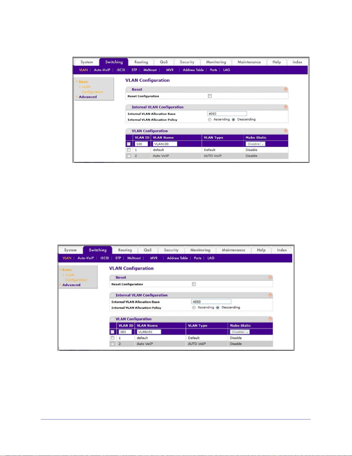
Web Interface: Create Two VLANS
1. Create VLAN2.
a. Select Switching > VLAN > Basic > VLAN Configuration.
A screen similar to the following displays.
b. Enter the following information:
• In the VLAN ID field, enter 2.
• In the VLAN Name field, enter VLAN2.
• In the VLAN T
ype list, select Static.
c. Click Add.
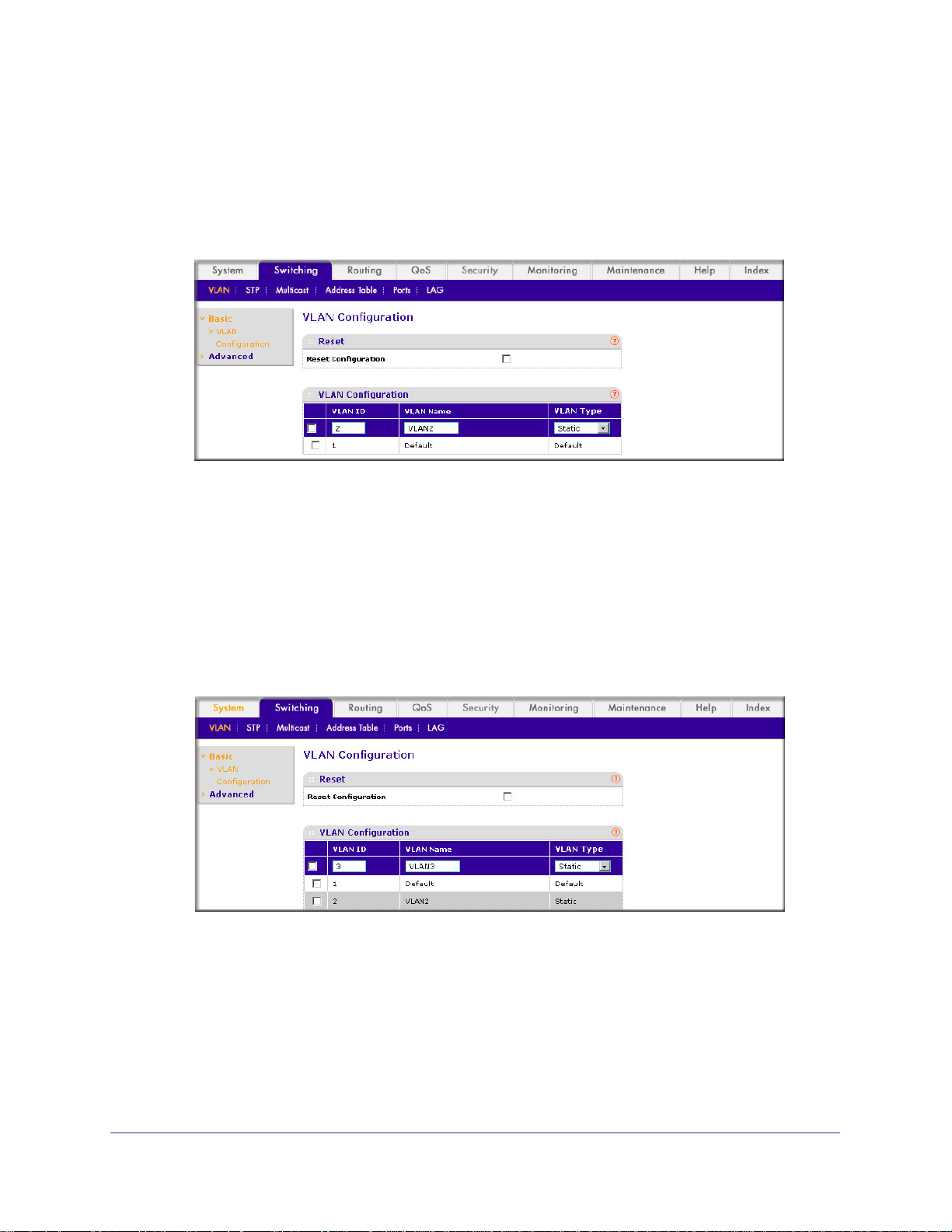
2. Create VLAN3.
a. Select Switching > VLAN > Basic > VLAN Configuration.
A screen similar to the following displays.
b. Enter the following information:
• In the VLAN ID field, enter 3.
• In the VLAN Name field, enter VLAN3.
• In the VLAN T
ype list, select Static.
c. Click Add.
18 | Chapter 2. VLANs
Page 19
ProSafe M4100 and M7100 Managed Switches
Assign Ports to VLAN2
This sequence shows how to assign ports to VLAN2, and to specify that frames will always
be transmitted tagged from all member ports and that untagged frames will be rejected on
receipt.
CLI: Assign Ports to VLAN2
(Netgear Switch) #config
(Netgear Switch) (Config)#interface range 1/0/1-1/0/2
(Netgear Switch) (conf-if-range-1/0/1-1/0/2)#vlan participation include 2
(Netgear Switch) (conf-if-range-1/0/1-1/0/2)#vlan acceptframe vlanonly
(Netgear Switch) (conf-if-range-1/0/1-1/0/2)#vlan pvid 2
(Netgear Switch) (conf-if-range-1/0/1-1/0/2)#exit
(Netgear Switch) (Config)#vlan port tagging all 2
(Netgear Switch) (Config)#
Web Interface: Assign Ports to VLAN2
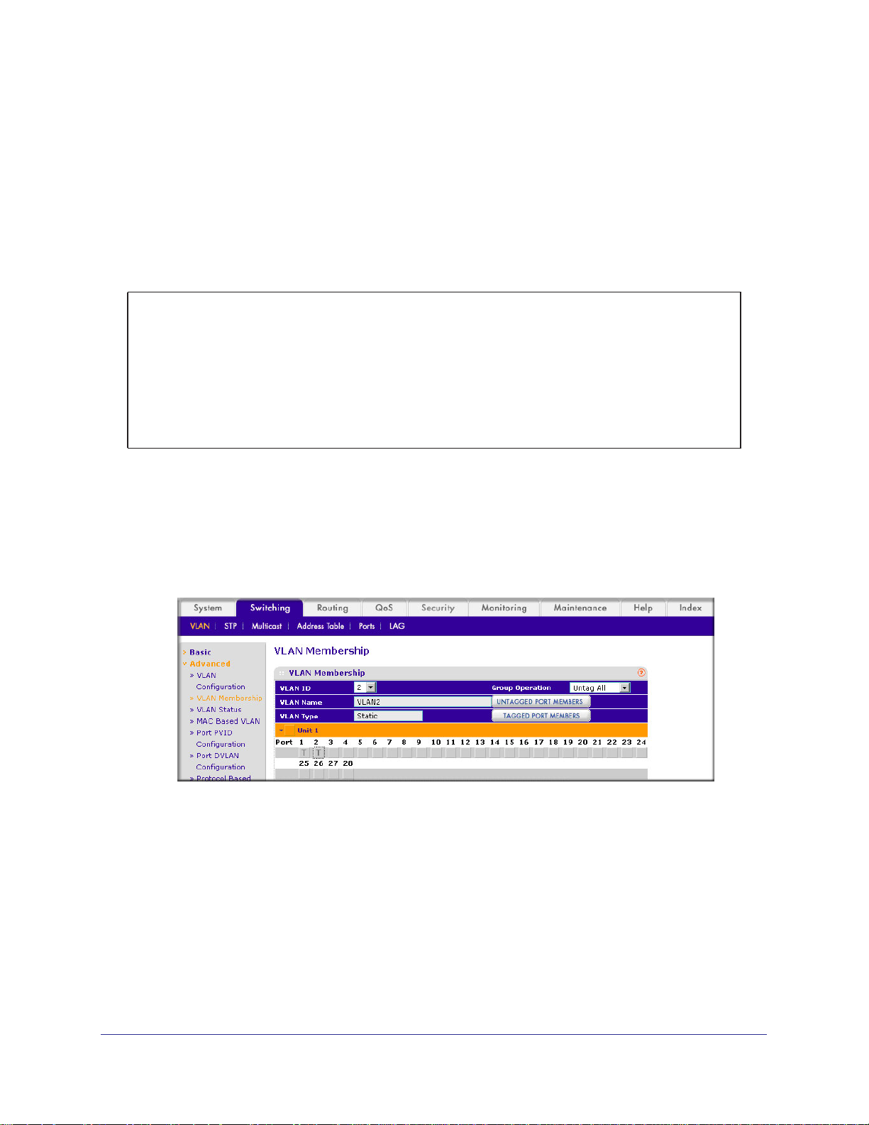
1. Assign ports to VLAN2.
a. Select Switching > VLAN >
A screen similar to the following displays.
b. In the VLAN ID list, select 2.
c. Click Unit 1.
The ports display.
d. Click the gray boxes under ports 1 and 2 until T displays.
The T specifies that the egress packet is tagged for the ports.
Advanced > VLAN Membership.
e. Click Apply to save the settings.
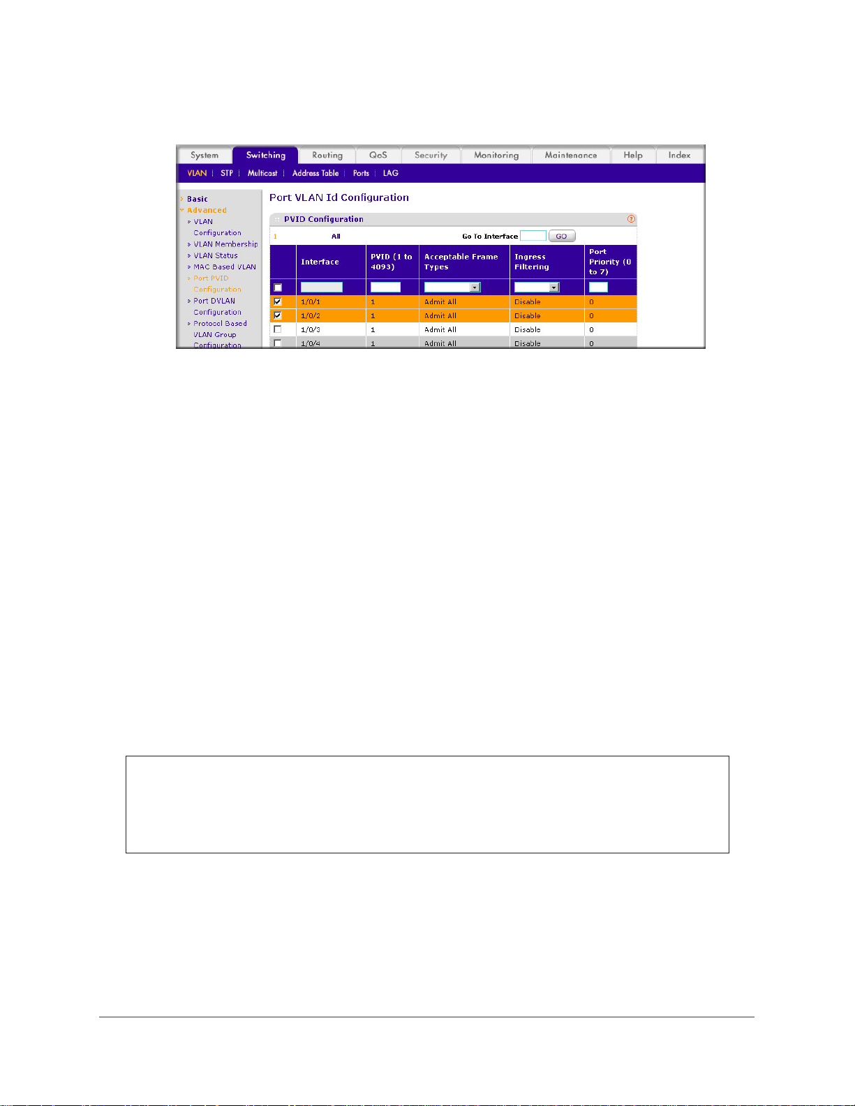
2. Specify that only tagged frames will be accepted on ports 1/0/1 and 1/0/2.
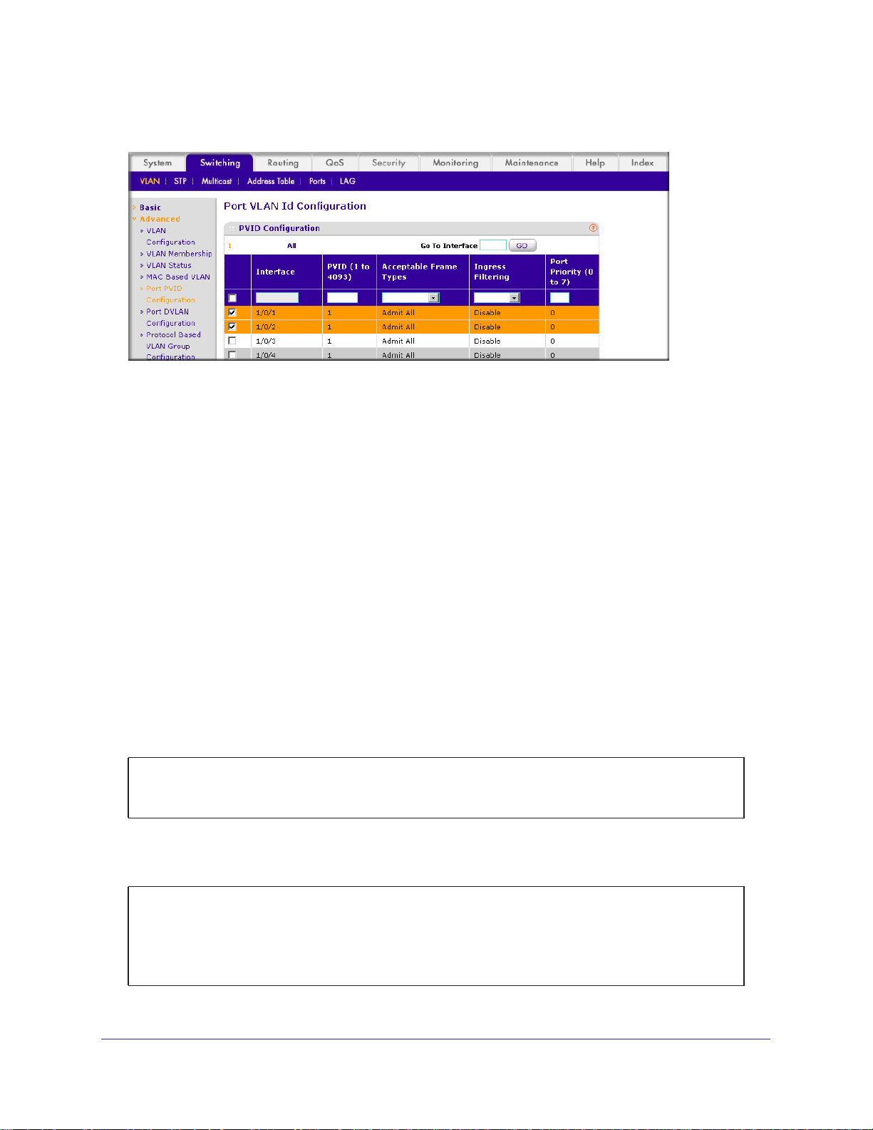
a. Select Switching > VLAN >
Advanced > Port PVID Configuration.
Chapter 2. VLANs | 19
Page 20
ProSafe M4100 and M7100 Managed Switches
A screen similar to the following displays.
b. Under PVID Configuration, scroll down and select the check box for Interface 1/0/1.
Then scroll down and select the Interface 1/0/2 check box.
c. Enter the following information:
• In the Acceptable Frame Type polyhedron list, select VLAN Only.
• In the PVID (1 to 4093) field, enter 2.
d. Click Apply to save the settings.
Create Three VLANs
The example is shown as CLI commands and as a Web interface procedure.
CLI: Create Three VLANS
Use the following commands to create three VLANs and to assign the VLAN IDs while
leaving the names blank.
(Netgear Switch) #vlan database
(Netgear Switch) (Vlan)#vlan 100
(Netgear Switch) (Vlan)#vlan 101
(Netgear Switch) (Vlan)#vlan 102
(Netgear Switch) (Vlan)#exit
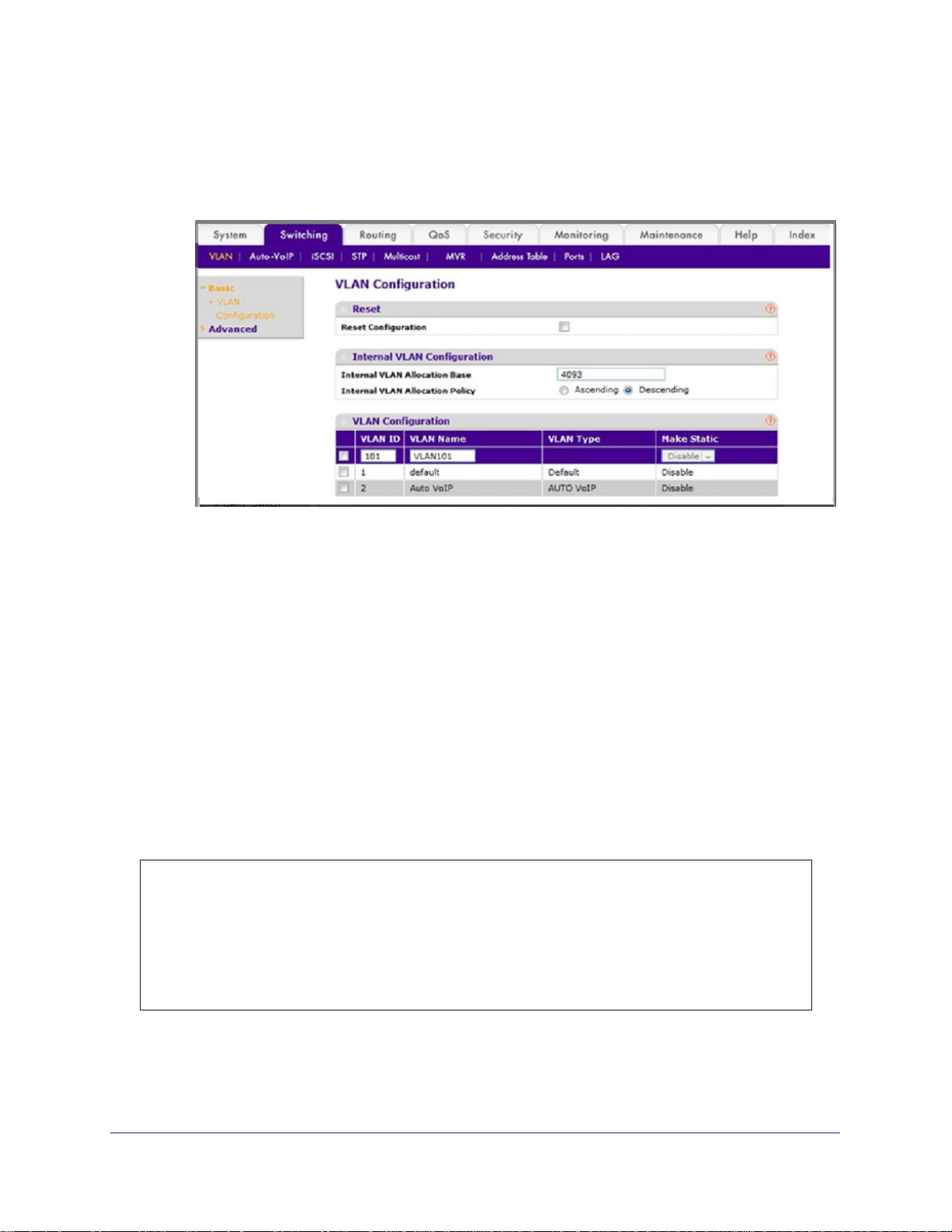
Web Interface: Create Three VLANS
1. Create VLAN100.
a. Select Switching > VLAN > Basic > VLAN Configuration.
20 | Chapter 2. VLANs
Page 21
ProSafe M4100 and M7100 Managed Switches
A screen similar to the following displays.
b. Enter the following information:
• In the VLAN ID field, enter 100.
• In the VLAN Name field, enter VLAN100.
c. Click Add.
2. Create VLAN101.
a. Select Switching > VLAN > Basic > VLAN Configuration.
A screen similar to the following displays.
b. Enter the following information:
• In the VLAN ID field, enter 101.
• In the VLAN Name field, enter VLAN101.
c. Click Add.
Chapter 2. VLANs | 21
Page 22
ProSafe M4100 and M7100 Managed Switches
3. Create VLAN102.
a. Select Switching > VLAN > Basic > VLAN Configuration.
A screen similar to the following displays.
b. Enter the following information:
• In the VLAN ID field, enter 102.
• In the VLAN Name field, enter VLAN102.
c. Click Add.
Assign Ports to VLAN3
This example shows how to assign the ports that will belong to VLAN 3, and to specify that
untagged frames will be accepted on port 1/0/4. Note that port 1/0/2 belongs to both VLANs
and that port 1/0/1 can never belong to VLAN 3.
CLI: Assign Ports to VLAN3
(Netgear Switch) (Config)#interface range 1/0/2-1/0/4
(Netgear Switch) (conf-if-range-1/0/2-1/0/4)#vlan participation include 3
(Netgear Switch) (conf-if-range-1/0/2-1/0/4)#exit
(Netgear Switch) (Config)#interface 1/0/4
(Netgear Switch) (Interface 1/0/4)#vlan acceptframe all
(Netgear Switch) (Interface 1/0/4)#exit
(Netgear Switch) (Config)#exit
22 | Chapter 2. VLANs
Page 23
ProSafe M4100 and M7100 Managed Switches
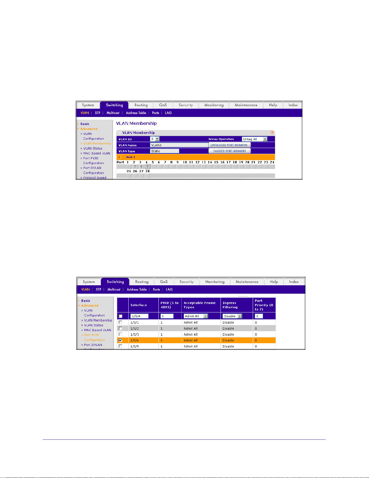
Web Interface: Assign Ports to VLAN3
1. Assign ports to VLAN3.
a. Select Switching > VLAN >
A screen similar to the following displays.
b. In the VLAN ID list, select 3.
c. Click Unit 1. The ports display
d. Click the gray boxes under ports 2, 3, and 4 until
Advanced > VLAN Membership.
.
T displays.
The T specifies that the egress packet is tagged for the ports.
e. Click Apply to save the settings.
2. Specify that untagged frames will be accepted on port 1/0/4.
a. Select Switching > VLAN >
A screen similar to the following displays.
b. Scroll down and select the Interface 1/0/4 check box.
Now 1/0/4 appears in the Interface field at the top.
c. In the Acceptable Frame T
d. Click Apply to save the settings.
Advanced > Port PVID Configuration.
ypes list, select Admit All.
Chapter 2. VLANs | 23
Page 24
ProSafe M4100 and M7100 Managed Switches
Assign VLAN3 as the Default VLAN for Port 1/0/2
This example shows how to assign VLAN 3 as the default VLAN for port 1/0/2.
CLI: Assign VLAN3 as the Default VLAN for Port 1/0/2
(Netgear Switch) #config
(Netgear Switch) (Config)#interface 1/0/2
(Netgear Switch) (Interface 1/0/2)#vlan pvid 3
(Netgear Switch) (Interface 1/0/2)#exit
(Netgear Switch) (Config)#exit
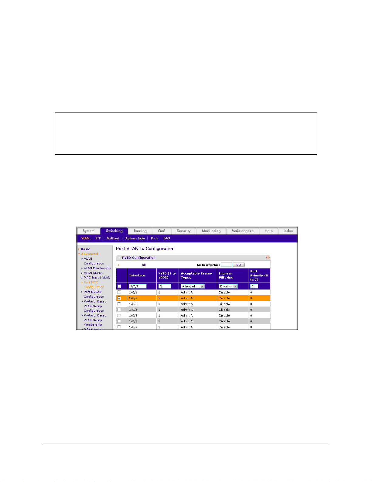
Web Interface: Assign VLAN3 as the Default VLAN for Port 1/0/2
1. Assign VLAN3 as the default VLAN for port 1/0/2.
a. Select Switching > VLAN >
to the following displays.
b. Under PVID Configuration, scroll down and select the Interface 1/0/2 check box.
Now 1/0/2 appears in the Interface field at the top.
c. In the PVID (1 to 4093) field, enter 3.
d. Click Apply to save the settings.
Advanced > Port PVID Configuration. A screen similar
24 | Chapter 2. VLANs
Page 25
ProSafe M4100 and M7100 Managed Switches
Create a MAC-Based VLAN
The MAC-based VLAN feature allows incoming untagged packets to be assigned to a VLAN
and thus classify traffic based on the source MAC address of the packet.
You define a MAC to VLAN mapping by configuring an entry in the MAC to VLAN table. An
entry is specified using a source MAC address and the appropriate VLAN ID. The MAC to
VLAN configurations are shared across all ports of the device (i.e., there is a system-wide
table that has MAC address to VLAN ID mappings).
When untagged or priority tagged packets arrive at the switch and entries exist in the MAC to
VLAN table, the source MAC address of the packet is looked up. If an entry is found, the
corresponding VLAN ID is assigned to the packet. If the packet is already priority tagged it
will maintain this value; otherwise, the priority will be set to 0 (zero).
The assigned VLAN ID is
verified against the VLAN table. If the VLAN is valid, ingress processing on the packet
continues; otherwise, the packet is dropped. This implies that you can configure a MAC
address mapping to a VLAN that has not been created on the system.
CLI: Create a MAC-Based VLAN
1. Create VLAN3
(Netgear Switch)#vlan database
(Netgear Switch)(Vlan)#vlan 3
(Netgear Switch)(Vlan)#exit
2. Add port 1/0/23 to VLAN3.
(Netgear Switch)#config
(Netgear Switch)(Config)#interface 1/0/23
(Netgear Switch)(Interface 1/0/23)#vlan participation include 3
(Netgear Switch)(Interface 1/0/23)#vlan pvid 3
(Netgear Switch)(Interface 1/0/23)#exit
.
Chapter 2. VLANs | 25
Page 26
ProSafe M4100 and M7100 Managed Switches
3. Map MAC 00:00:0A:00:00:02 to VLAN3.
(Netgear Switch)(Config)#exit
(Netgear Switch)#vlan data
(Netgear Switch)(Vlan)#vlan association mac 00:00:00A:00:00:02 3
(Netgear Switch)(Vlan)#exit
4. Add all the ports to VLAN3.
(Netgear Switch)#config
(Netgear Switch)(Config)#interface range 1/0/1-1/0/28
(Netgear Switch)(conf-if-range-1/0/1-1/0/28)#vlan participation include 3
(Netgear Switch)(conf-if-range-1/0/1-1/0/28)#exit
(Netgear Switch)(Config)#exit
Web Interface: Assign a MAC-Based VLAN
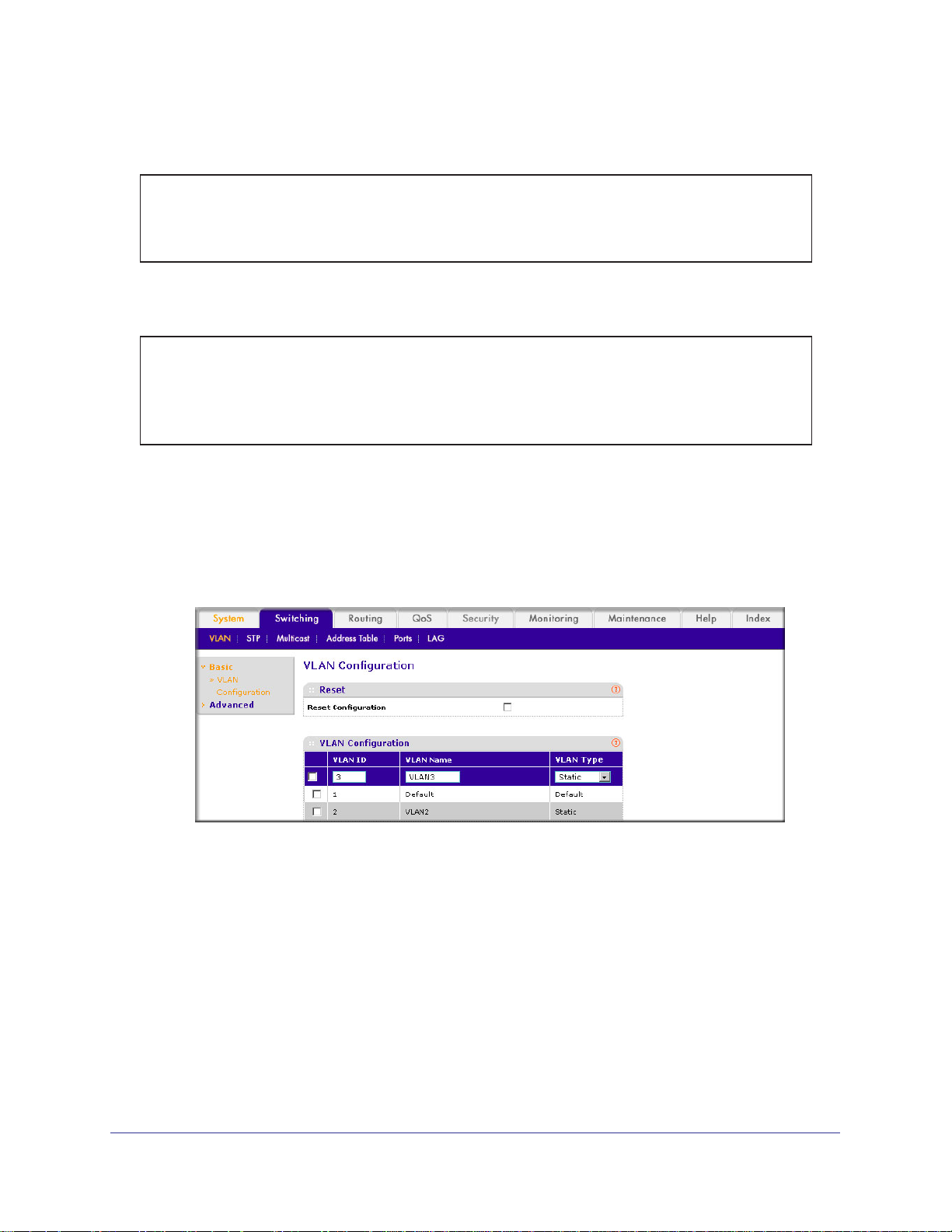
1. Create VLAN3.
a. Select Switching > VLAN > Basic > VLAN Configuration.
A screen similar to the following displays.
b. Enter the following information:
• In the VLAN ID field, enter 3.
• In the VLAN Name field, enter VLAN3.
• In the VLAN T
ype list, select Static.
c. Click Add.
2. Assign ports to VLAN3.
a. Select Switching > VLAN >
Advanced > VLAN Membership.
26 | Chapter 2. VLANs
Page 27
ProSafe M4100 and M7100 Managed Switches
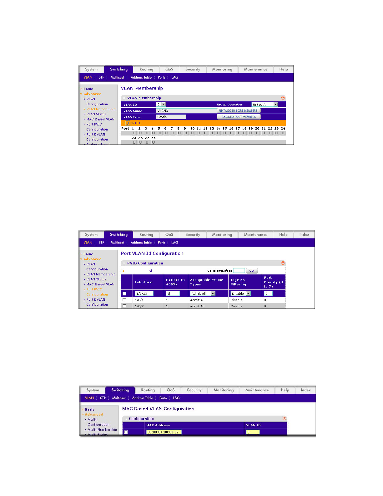
A screen similar to the following displays.
b. In the VLAN ID list, select 3.
c. Click Unit 1. The ports display
d. Click the gray box before Unit 1 until U displays.
e. Click Apply.
3. Assign
a. Select Switching > VLAN >
VPID3 to port 1/0/23.
Advanced > Port PVID Configuration.
.
A screen similar to the following displays.
b. Scroll down and select the 1/0/23 check box.
c. In the PVID (1 to 4093) field, enter 3.
d. Click Apply to save the settings.
4. Map the specific MAC to VLAN3.
a. Select Switching > VLAN >
Advanced > MAC based VLAN.
A screen similar to the following displays.
Chapter 2. VLANs | 27
Page 28

ProSafe M4100 and M7100 Managed Switches
b. Enter the following information:
• In the MAC Address field, enter 00:00:0A:00:00:02.
• In the PVID (1 to 4093) field, enter 3.
c. Click Add.
Create a Protocol-Based VLAN
Create two protocol VLAN groups. One is for IPX and the other is for IP/ARP. The untagged
IPX packets are assigned to VLAN 4, and the untagged IP/ARP packets are assigned to
VLAN 5.
CLI: Create a Protocol-Based VLAN
1. Create a VLAN protocol group vlan_ipx based on IPX protocol.
(Netgear Switch)#config
(Netgear Switch)(Config)#vlan protocol group vlan_ipx
(Netgear Switch)(Config)#vlan protocol group add protocol 1 ipx
2. Create a VLAN protocol group vlan_ipx based on IP/ARP protocol.
(Netgear Switch)(Config)#vlan protocol group vlan_ip
(Netgear Switch)(Config)#vlan protocol group add protocol 2 ip
(Netgear Switch)(Config)#vlan protocol group add protocol 2 arp
(Netgear Switch)(Config)#exit
3. Assign VLAN protocol group 1 to VLAN 4.
(Netgear Switch)#vlan database
(Netgear Switch)(Vlan)#vlan 4
(Netgear Switch)(Vlan)#vlan 5
(Netgear Switch)(Vlan)#protocol group 1 4
4. Assign VLAN protocol group 2 to VLAN 5.
(Netgear Switch)(Vlan)#protocol group 2 5
28 | Chapter 2. VLANs
Page 29
ProSafe M4100 and M7100 Managed Switches
5. Enable protocol VLAN group 1 and 2 on the interface.
(Netgear Switch)(Vlan)#exit
(Netgear Switch)#config
(Netgear Switch)(Config)#interface 1/0/11
(Netgear Switch)(Interface 1/0/11)#protocol vlan group 1
(Netgear Switch)(Interface 1/0/11)#protocol vlan group 2
(Netgear Switch)(Interface 1/0/11)#exit
Web Interface: Create a Protocol-Based VLAN
1. Create the protocol-based VLAN group vlan_ipx.
a. Select Switching > VLAN >
Configuration.
A screen similar to the following displays.
Advanced > Protocol Based VLAN Group
Enter the following information:
• In the Group Name field, enter vlan_ipx.
• In the Protocol list, select IPX.
• In the VLAN ID field, enter 4.
b. Click Add.
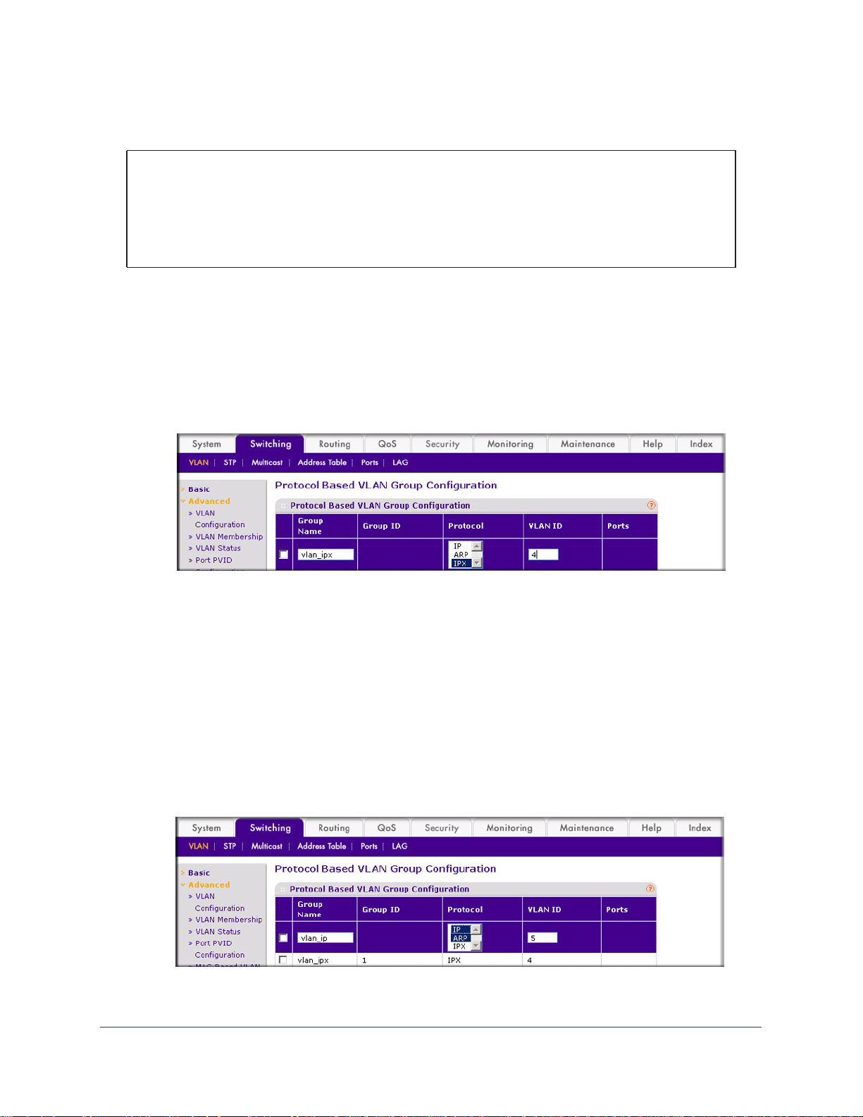
2. Create the protocol-based VLAN group vlan_ip.
a. Select Switching > VLAN >Advanced > Protocol Based VLAN Group
Configuration.
A screen similar to the following displays.
Chapter 2. VLANs | 29
Page 30

b. Enter the following information:
• In the Group Name field, enter vlan_ip.
• In the Protocol list, select IP and ARP while holding down the Ctrl key.
• In the VLAN field, enter 5.
c. Click Add.
3. Add port 1
1 to the group vlan_ipx.
a. Select Switching > VLAN >
Membership.
A screen similar to the following displays.
ProSafe M4100 and M7100 Managed Switches
Advanced > Protocol Based VLAN Group
b. In the Group ID list, select 1.
c. Click the gray box under port 11.
d. Click the Apply button.
4. Add port 1
1 to the group vlan_ip.
a. Select Switching > VLAN >
Membership.
A screen similar to the following displays.
b. In the Group ID list, select 2.
c. Click the gray box under port 11.
d. Click Apply.
A check mark displays in the box.
Advanced > Protocol Based VLAN Group
A check mark displays in the box.
30 | Chapter 2. VLANs
Page 31

ProSafe M4100 and M7100 Managed Switches
Virtual VLANs: Create an IP Subnet–Based VLAN
In an IP subnet–based VLAN, all the end workstations in an IP subnet are assigned to the
same VLAN. In this VLAN, users can move their workstations without reconfiguring their
network addresses. IP subnet VLANs are based on Layer 3 information from packet headers.
The switch makes use of the network-layer address (for example, the subnet address for
TCP/IP networks) in determining VLAN membership. If a packet is untagged or priority
tagged, the switch associates the packet with any matching IP subnet classification. If no IP
subnet classification can be made, the packet is subjected to the normal VLAN classification
rules of the switch. This IP subnet capability does not imply a routing function or that the
VLAN is routed. The IP subnet classification feature affects only the VLAN assignment of a
packet. Appropriate 802.1Q VLAN configuration must exist in order for the packet to be
switched.
1/0/1
PC 1 PC 2
10.100.5.1 10.100.5.30
Figure 2. IP subnet–based VLAN
Switch
1/0/24
CLI: Create an IP Subnet–Based VLAN
(Netgear Switch) #vlan database
(Netgear Switch) (Vlan)#vlan 2000
(Netgear Switch) (Vlan)#vlan association subnet 10.100.0.0 255.255.0.0 2000
(Netgear Switch) (Vlan)#exit
Create an IP subnet–based VLAN 2000.
(Netgear Switch) #config
(Netgear Switch) (Config)#interface range 1/0/1-1/0/24
(Netgear Switch) (conf-if-range-1/0/1-1/0/24)# vlan participation include 2000
(Netgear Switch) (conf-if-range-1/0/1-1/0/24)#exit
(Netgear Switch) (Config)#
Chapter 2. VLANs | 31
Page 32
ProSafe M4100 and M7100 Managed Switches
Assign all the ports to VLAN 2000.
(Netgear Switch) #show mac-addr-table vlan 2000
MAC Address Interface Status
----------------- --------- -----------00:00:24:58:F5:56 1/0/1 Learned
00:00:24:59:00:62 1/0/24 Learned
Web Interface: Create an IP Subnet–Based VLAN
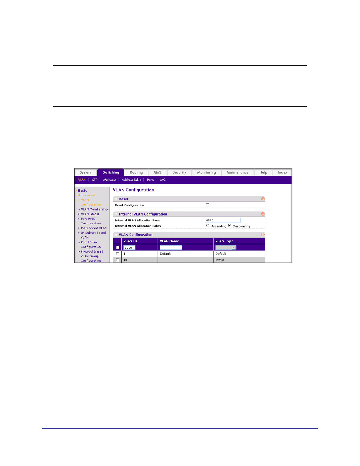
1. Create VLAN 2000.
a. Select Switching > VLAN > Basic > VLAN Configuration.
A screen similar to the following displays.
b. Enter the following information:
• In the VLAN ID field, enter 2000.
• In the VLAN Type list, select Static.
c. Click Add.
2. Assign all the ports to VLAN 2000.
a. Select Switching > VLAN >
32 | Chapter 2. VLANs
Advanced > VLAN Membership.
Page 33
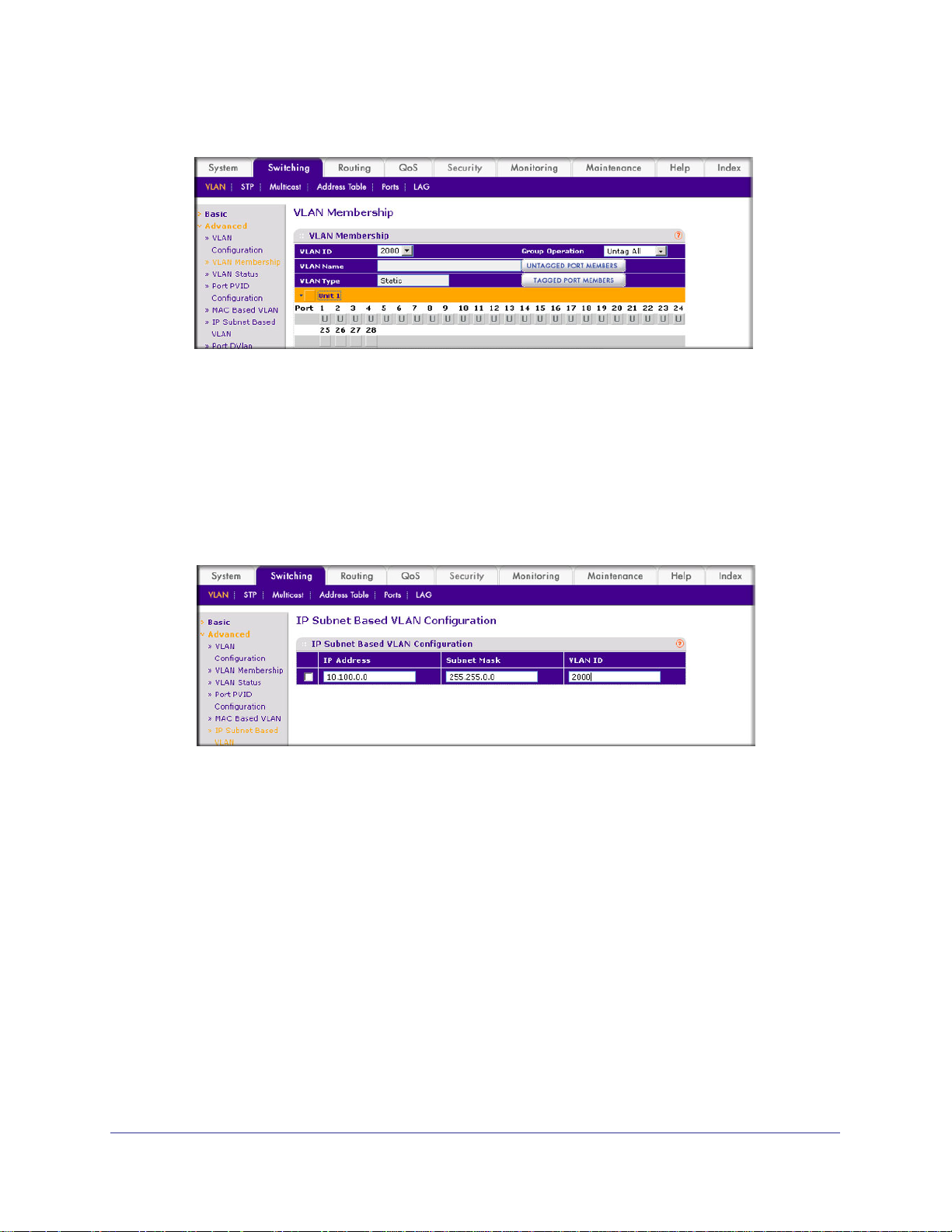
ProSafe M4100 and M7100 Managed Switches
A screen similar to the following displays.
b. In the VLAN ID list, select 2000.
c. Click Unit 1.
d. Click the gray box before Unit 1 until U displays.
e. Click Apply.
3. Associate the IP subnet with VLAN 2000.
a. Select Switching > VLAN >
The ports display.
Advanced > IP Subnet Based VLAN.
A screen similar to the following displays.
b. Enter the following information:
• In the IP Address field, enter 10.100.0.0.
• In the Subnet Mask field, enter 255.255.0.0.
• In the VLAN (1 to 4093) field, enter 2000.
c. Click Add.
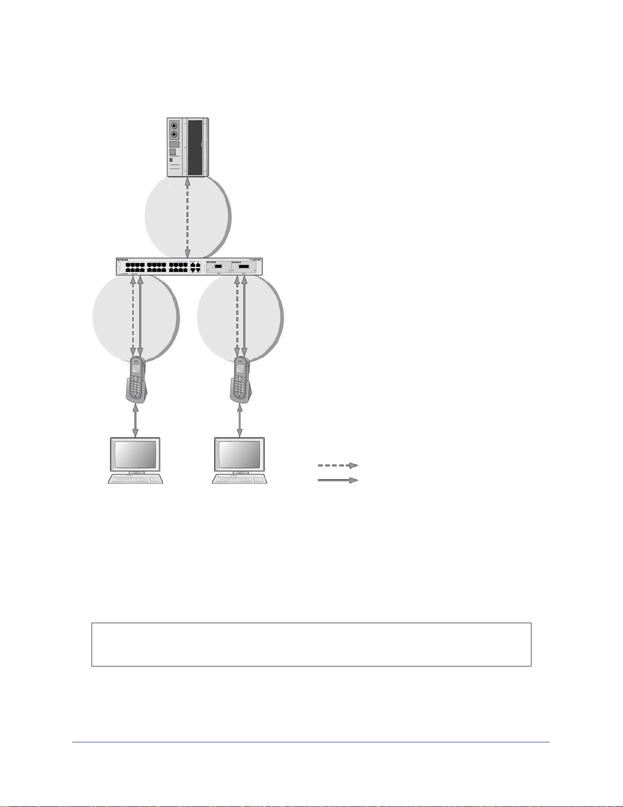
Voice VLANs
The voice VLAN feature enables switch ports to carry voice traffic with defined priority to
enable separation of voice and data traffic coming onto port. Voice VLAN ensures that the
sound quality of an IP phone does not deteriorate when the data traffic on the port is high.
Also, the inherent isolation provided by VLANs ensures that inter-VLAN traffic is under
Chapter 2. VLANs | 33
Page 34
ProSafe M4100 and M7100 Managed Switches
management control and that clients attached to the network cannot initiate a direct attack on
voice components.
PBX
1/0/1
GSM73xxS
1/0/2
VoIP
phone
PC
1/0/3
VoIP
phone
PC
Voice traffic
Data traffic
Figure 3. Voice VLAN
The script in this section shows how to configure Voice VLAN and prioritize the voice traffic.
Here the Voice VLAN mode is in VLAN ID 10.
CLI: Configure Voice VLAN and Prioritize Voice Traffic
1. Create VLAN 10.
(Netgear Switch) #vlan database
(Netgear Switch) (Vlan)#vlan 10
(Netgear Switch) (Vlan)#exit
34 | Chapter 2. VLANs
Page 35

ProSafe M4100 and M7100 Managed Switches
2. Include the ports 1/0/1 and 1/0/2 in VLAN 10.
(Netgear Switch) (Config)#interface range 1/0/1-1/0/2
(Netgear Switch) (conf-if-range-1/0/1-1/0/2)#vlan participation include 10
(Netgear Switch) (conf-if-range-1/0/1-1/0/2)#vlan tagging 10
(Netgear Switch) (conf-if-range-1/0/1-1/0/2)#exit
3. Configure Voice VLAN globally.
(Netgear Switch) (Config)# voice vlan
4. Configure Voice VLAN mode in the interface 1/0/2.
(Netgear Switch) (Config)#interface 1/0/2
(Netgear Switch) (Interface 1/0/2)#voice vlan 10
(Netgear Switch) (Interface 1/0/2)#exit
5. Create the DiffServ class ClassVoiceVLAN.
(Netgear Switch) (Config)#class-map match-all ClassVoiceVLAN
6. Configure VLAN 10 as the matching criteria for the class.
(Netgear Switch) (Config-classmap)#match vlan 10
7. Create the DiffServ policy PolicyVoiceVLAN.
(Netgear Switch) (Config)#policy-map PolicyVoiceVLAN in
8. Map the policy and class and assign them to the higher-priority queue.
(Netgear Switch) (Config-policy-map)#class ClassVoiceVLAN
(Netgear Switch) (Config-policy-classmap)#assign-queue 3
(Netgear Switch) (Config-policy-classmap)#exit
9. Assign it to interfaces 1/0/1 and 1/0/2.
(Netgear Switch) (Config)#interface range 1/0/1-1/0/2
(Netgear Switch) (conf-if-range-1/0/1-1/0/2)# service-policy in PolicyVoiceVLAN
Chapter 2. VLANs | 35
Page 36
ProSafe M4100 and M7100 Managed Switches
Web Interface: Configure Voice VLAN and Prioritize Voice Traffic
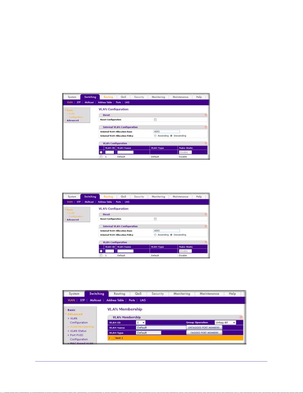
1. Create VLAN 10.
a. Select Switching > VLAN > Basic > VLAN Configuration.
A screen similar to the following displays.
b. In the VLAN ID field, enter 10.
c. In the VLAN Name field, enter V
d. Click Add. A
screen similar to the following displays.
oice VLAN.
2. Include the ports 1/0/1 and 1/0/2 in VLAN 10.
a. Select Switching > VLAN >
A screen similar to the following displays.
36 | Chapter 2. VLANs
Advanced > VLAN Membership.
Page 37

ProSafe M4100 and M7100 Managed Switches
b. In the VLAN Membership table, in the VLAN ID list, select 10.
c. Select Port 1 and Port 2 as tagged.
A screen similar to the following displays.
d. Click Apply.
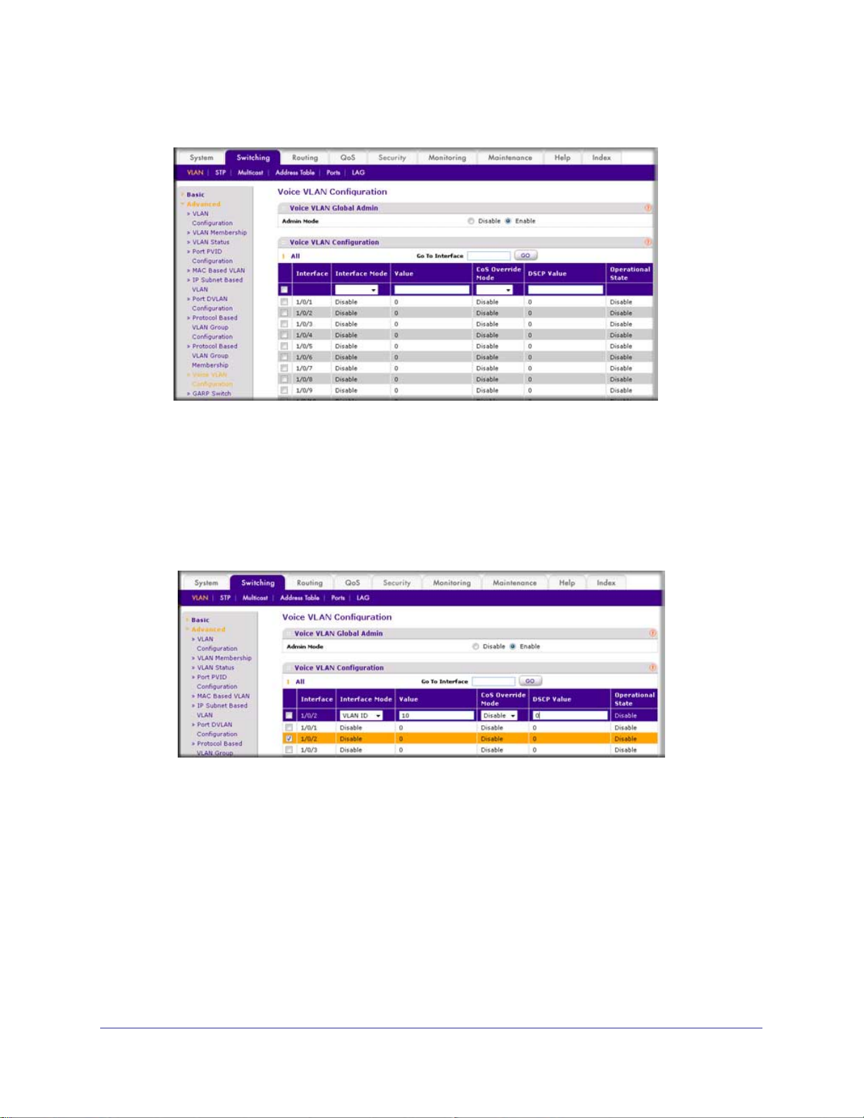
3. Configure V
a. Select Switching > VLAN >
oice VLAN globally.
Advanced > Voice VLAN Configuration.
A screen similar to the following displays.
b. For Admin
Mode, select the Enable radio button.
c. Click Apply.
Chapter 2. VLANs | 37
Page 38
ProSafe M4100 and M7100 Managed Switches
A screen similar to the following displays.
4. Configure Voice VLAN mode in the interface 1/0/2.
a. Select Switching > VLAN >
Advanced > Voice VLAN Configuration.
b. Select the 1/0/2 check box.
c. In the Interface Mode list, select VLAN ID.
d. In the V
alue field, enter 10.
A screen similar to the following displays.
e. Click Apply.
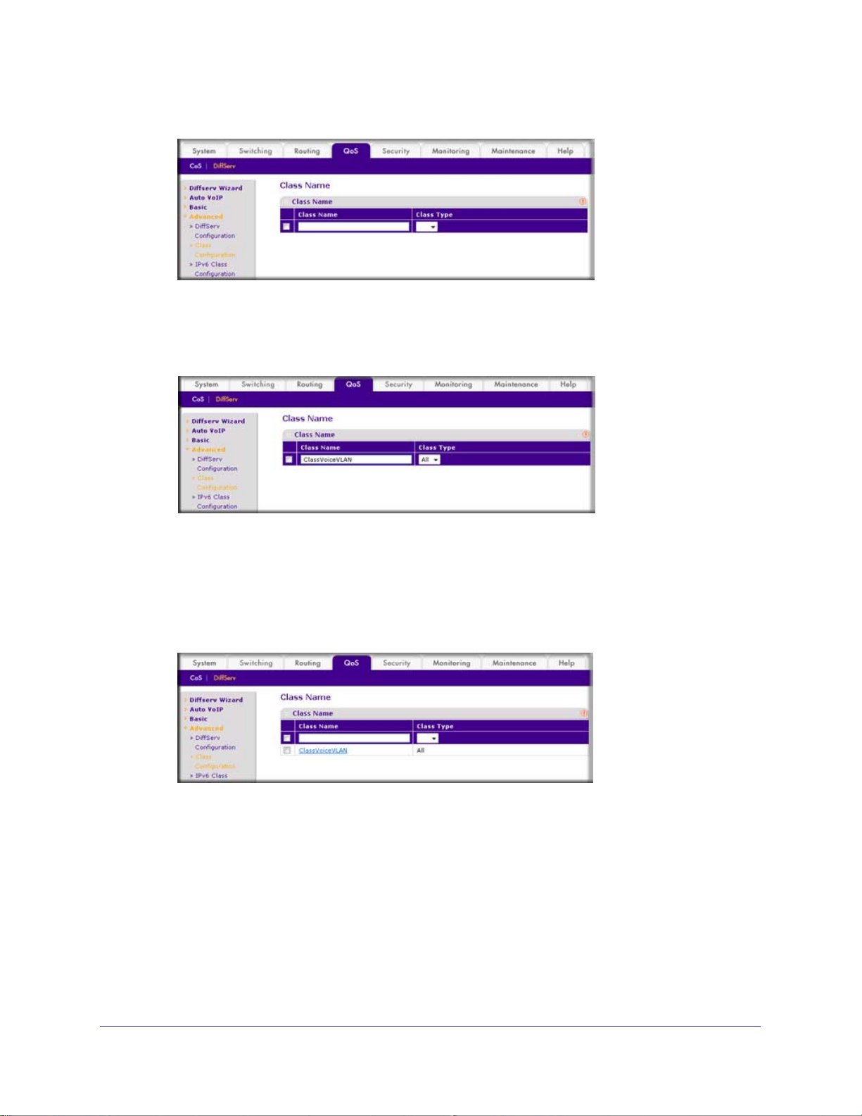
5. Create the Dif
a. Select QoS >
fServ class ClassVoiceVLAN.
Advanced > DiffServ > Class Configuration.
38 | Chapter 2. VLANs
Page 39
ProSafe M4100 and M7100 Managed Switches
A screen similar to the following displays.
b. In the Class Name field, enter ClassVoiceVLAN.
c. In the Class T
ype list, select All.
A screen similar to the following displays.
d. Click Add. The Class Name screen displays, as shown in the next step in this
procedure.
6. Configure matching criteria for the class as VLAN 10.
a. Select QoS > DiffServ >
Advanced > Class Configuration.
A screen similar to the following displays.
b. Click the class ClassVoiceVLAN.
Chapter 2. VLANs | 39
Page 40

ProSafe M4100 and M7100 Managed Switches
A screen similar to the following displays.
c. In the DiffServ Class Configuration table, select VLAN.
d. In the VLAN ID field, enter 10.
A screen similar to the following displays.
e. Click Apply.
A screen similar to the following displays.
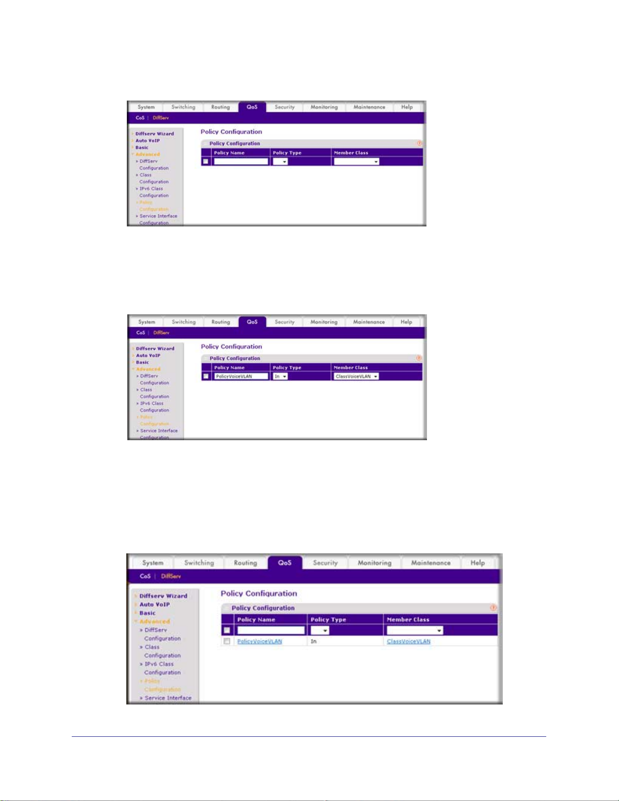
7. Create the DiffServ policy PolicyVoiceVLAN.
a. Select QoS > DiffServ >
Advanced > Policy Configuration.
40 | Chapter 2. VLANs
Page 41
ProSafe M4100 and M7100 Managed Switches
A screen similar to the following displays.
b. In the Policy Name field, enter PolicyVoiceVLAN.
c. In the Policy T
ype list, select In.
d. In the Member Class list, select ClassV
A screen similar to the following displays.
oiceVLAN.
e. Click Add.
The Policy Configuration screen displays, as shown in the next step in this procedure.
8. Map the policy and class and assign them to the higher-priority queue.
a. Select QoS > DiffServ >
Advanced > Policy Configuration.
A screen similar to the following displays.
Chapter 2. VLANs | 41
Page 42

ProSafe M4100 and M7100 Managed Switches
b. Click the Policy PolicyVoiceVLAN.
A screen similar to the following displays.
c. In the field next to the Assign Queue radio button, select 3.
A screen similar to the following displays.
d. Click Apply.
9. Assign it to interfaces 1/0/1 and 1/0/2.
a. Select QoS > DiffServ >
A screen similar to the following displays.
b. Select the check boxes for Interfaces 1/0/1 and 1/0/2.
c. Set the Policy Name field as PolicyV
42 | Chapter 2. VLANs
Advanced > Service Interface Configuration.
oiceVLAN.
Page 43

ProSafe M4100 and M7100 Managed Switches
A screen similar to the following displays.
d. Click Apply.
A screen similar to the following displays.
Chapter 2. VLANs | 43
Page 44

ProSafe M4100 and M7100 Managed Switches
Private VLANs
The Private VLANs feature separates a regular VLAN domain into two or more subdomains.
Each subdomain is defined (represented) by a primary VLAN and a secondary VLAN. The
primary VLAN ID is the same for all subdomains that belong to a private VLAN. The
secondary VLAN ID differentiates subdomains from each other and provides Layer 2 isolation
between ports of the same private VLAN.
There are three types of VLAN within a private VLAN:
• Primary VLAN - it forwards the traf
community ports, and other promiscuous ports in the same private VLAN. Only one
primary VLAN can be configured per private VLAN. All ports within a private VLAN
share the same primary VLAN.
• Community VLAN - is a secondary VLAN. It forwards traf
belong to the same community and to the promiscuous ports. There can be multiple
community VLANs per private VLAN.
• Isolated VLAN - is a secondary VLAN. It carries traf
promiscuous ports. Only one isolated VLAN can be configured per private VLAN.
There are three types of port designation within a private VLAN:
• Promiscuous port - belongs to a primary VLAN and can communicate with all
interfaces in the private VLAN, including other promiscuous ports, community ports,
and isolated ports.
• Community ports -
promiscuous ports.
• Isolated ports -
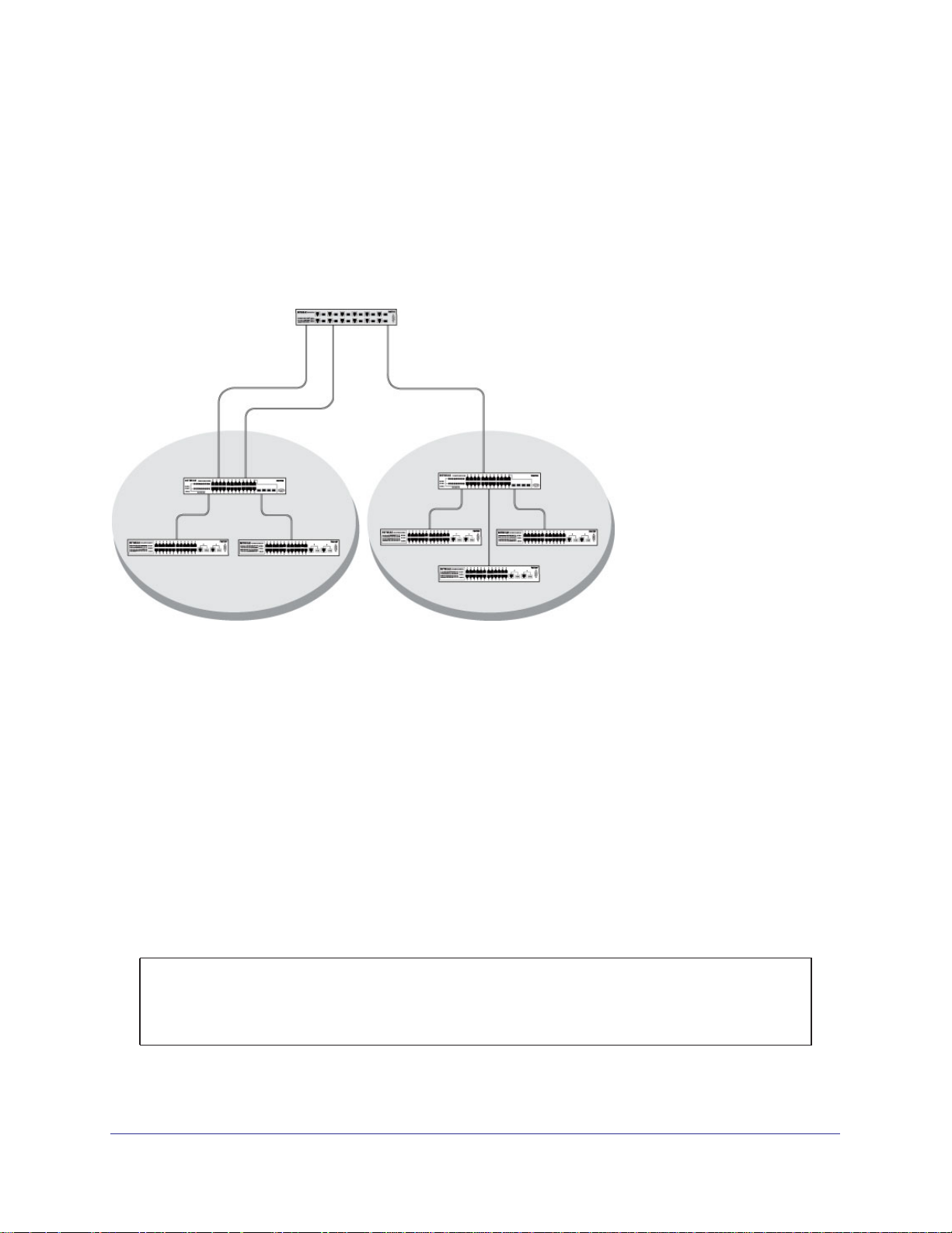
The Private VLANs can be extended across multiple switches through inter-switch/stack links
that transport primary
, community, and isolated VLANs between devices. See figure 1.
These ports can communicate with other community ports and
These can ONLY communicate with promiscuous ports.
fic from the promiscuous ports to isolated ports,
fic between ports which
fic from isolated ports to
Figure 4. Private VLANs
44 | Chapter 2. VLANs
Page 45

ProSafe M4100 and M7100 Managed Switches
Figure 2 illustrates the private VLAN traffic flow. Five ports A, B, C, D, and E make up a
private VLAN. Port A is a promiscuous port which is associated with the primary VLAN 100.
Ports B and C are the host ports which belong to the isolated VLAN 101. Ports D and E are
the community ports which are associated with community VLAN 102. Port F is the
inter-switch/stack link. It is configured to transmit VLANs 100, 101 and 102. Colored arrows
represent possible packet flow paths in the private VLAN domain.
Figure 5. Packet flow within a Private VLAN domain
Chapter 2. VLANs | 45
Page 46

ProSafe M4100 and M7100 Managed Switches
Assign Private-VLAN Types (Primary, Isolated, Community)
The example is shown as CLI commands and as a Web interface procedure.
CLI: Assign Private-VLAN Type (Primary, Isolated, Community)
Use the following commands to assign VLAN 100 to primary VLAN, VLAN 101 to isolated
VLAN, and VLAN 102 to community VLAN.
(Netgear Switch) #config
(Netgear Switch) (Config)#vlan 100
(Netgear Switch) (Config)(Vlan) #private-vlan primary
(Netgear Switch) (Config)(Vlan) #exit
(Netgear Switch) (Config)#vlan 101
(Netgear Switch) (Config)(Vlan) #private-vlan isolated
(Netgear Switch) (Config)(Vlan) #exit
(Netgear Switch) (Config)#vlan 102
(Netgear Switch) (Config)(Vlan) #private-vlan community
(Netgear Switch) (Config)(Vlan) #end
Web Interface: Assign Private-VLAN Type (Primary, Isolated, Community)
1. Create VLAN 10.
a. Select Security > T
Configuration. A screen similar to the following displays.
b. Under Private VLAN Type Configuration, select the VLAN ID 100 check box. Now
100 appears in the interface field at the top.
c. In the Private VLAN T
d. Click Apply to save the settings
raffic Control > Private VLAN > Private VLAN Type
ype field, select Primary from the pull-down menu.
46 | Chapter 2. VLANs
Page 47

ProSafe M4100 and M7100 Managed Switches
2. Assign VLAN 101 as an isolated VLAN.
a. Select Security > T
raffic Control > Private VLAN > Private VLAN Type
Configuration.
A screen similar to the following displays.
b. Under Private VLAN Type Configuration, select the VLAN ID 101 check box.
Now 101 appears in the interface field at the top.
c. In the Private VLAN T
ype field, select Isolated from the pull-down menu.
d. Click Apply to save the settings
3. Assign VLAN 102 to community VLAN.
a. Select Security > T
raffic Control > Private VLAN > Private VLAN Type
Configuration.
A screen similar to the following displays.
b. Under Private VLAN Type Configuration, select the VLAN ID 102 check box. Now
102 appears in the interface field at the top.
c. In the Private VLAN T
ype field, select Community from the pull-down menu.
d. Click Apply to save the settings.
Chapter 2. VLANs | 47
Page 48
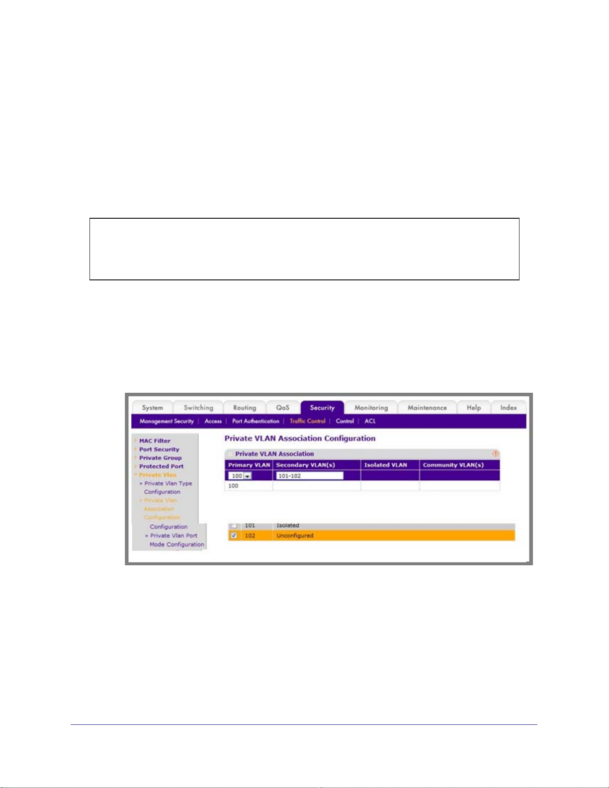
ProSafe M4100 and M7100 Managed Switches
Configure Private-VLAN Association
The example is shown as CLI commands and as a Web interface procedure.
CLI: Configure Private-VLAN Association
Use the following commands to associate VLAN 101-102 (secondary VLAN) to VLAN 100
(primary VLAN).
(Netgear Switch) #config
(Netgear Switch) (Config)#vlan 100
(Netgear Switch) (Config)(Vlan) #private-vlan association 101-102
(Netgear Switch) (Config)(Vlan) #end
Web Interface: Configure Private-VLAN Association
1. Associate VLAN 101-102 (secondary VLAN) to VLAN 100 (primary VLAN).
a. Select Security > T
Configuration.
A screen similar to the following displays.
b. Under Private VLAN Association Configuration, select the VLAN ID 100.
c. In the Secondary VLAN(s) field, type 101-102.
d. Click Apply to save the settings.
raffic Control > Private VLAN > Private VLAN Association
48 | Chapter 2. VLANs
Page 49
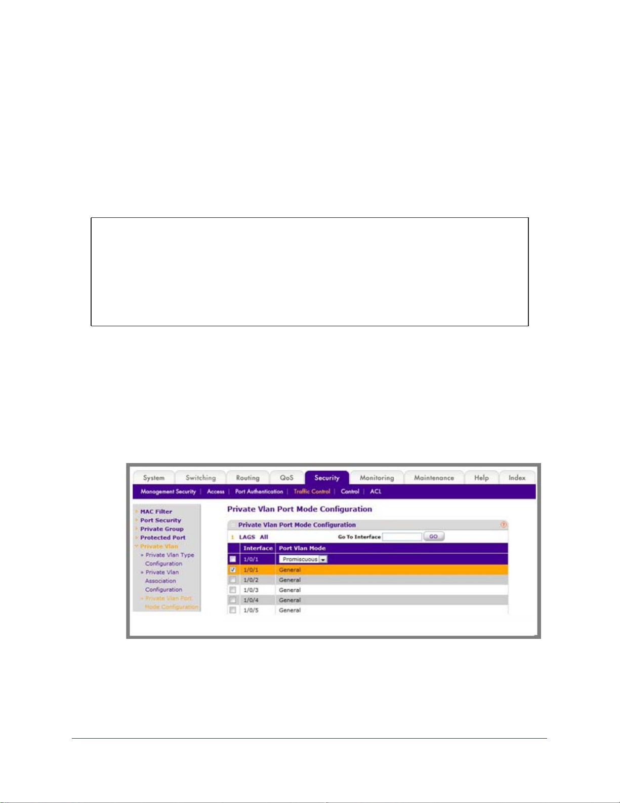
ProSafe M4100 and M7100 Managed Switches
Configure Private-VLAN Port Mode (Promiscuous, Host)
The example is shown as CLI commands and as a Web interface procedure.
CLI: Configure Private-VLAN Port Mode (Promiscuous, Host)
Use the following commands to assign port 1/0/1 to promiscuous port mode and ports
1/0/2-1/0/5 to host port mode.
(Netgear Switch) #config
(Netgear Switch) (Config)#interface 1/0/1
(Netgear Switch) (Interface 1/0/1)#switchport mode private-vlan promiscuous
(Netgear Switch) (Interface 1/0/1)#exit
(Netgear Switch) (Config)#interface 1/0/2-1/0/5
(Netgear Switch) (Interface 1/0/2-1/0/5)#switchport mode private-vlan host
(Netgear Switch) (Interface 1/0/2-1/0/5)#end
Web Interface: Configure Private-VLAN Port Mode (Promiscuous, Host)
1. Configure port 1/0/1 to promiscuous port mode.
a. Select Security > T
Configuration.
A screen similar to the following displays.
raffic Control > Private VLAN > Private VLAN Port Mode
b. Under Private VLAN Port Mode Configuration, select the 1/0/1 interface check
box.
Now 1/0/1 appears in the Interface field at the top.
c. In the Port VLAN Mode field, select Promiscuous from the pull-down menu.
Chapter 2. VLANs | 49
Page 50
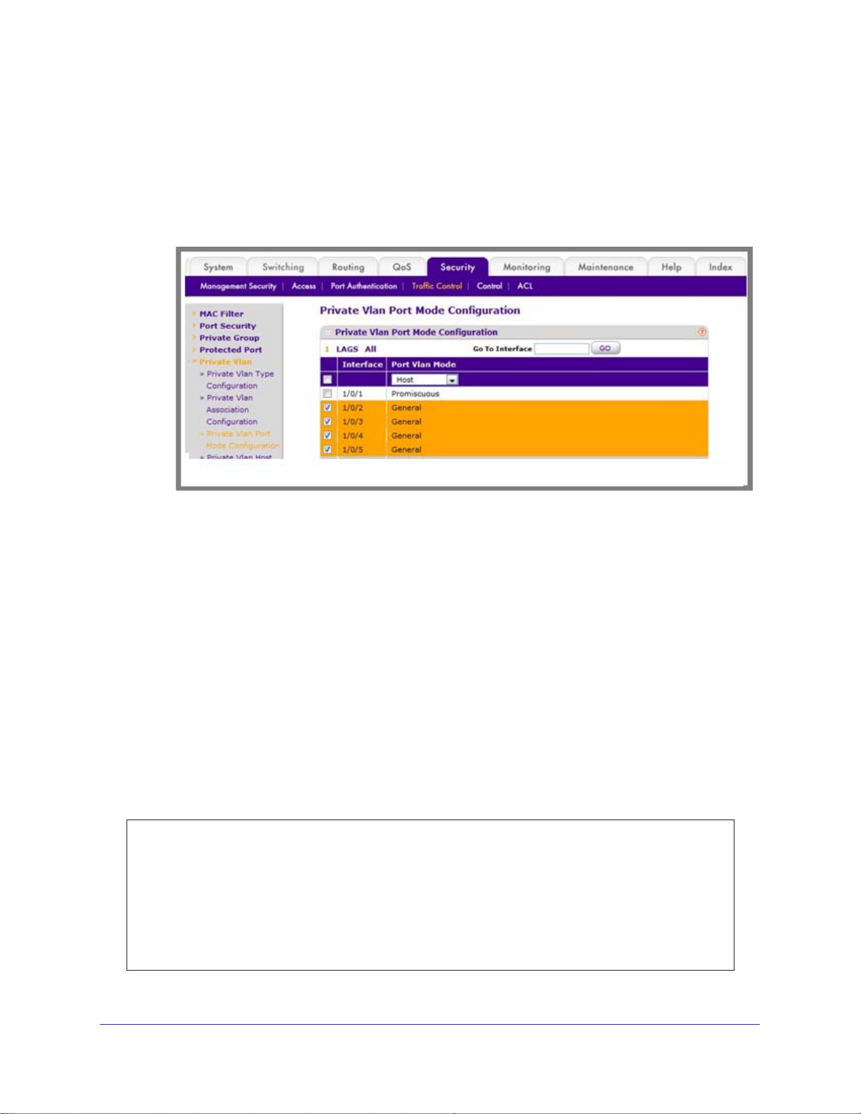
d. Click Apply to save the settings.
2. Configure ports 1/0/2-1/0/5 to host port mode.
a. Select Security > T
Configuration.
A screen similar to the following displays.
raffic Control > Private VLAN > Private VLAN Port Mode
ProSafe M4100 and M7100 Managed Switches
b. Under Private VLAN Port Mode Configuration, select the 1/0/2 to 1/0/5 interface
check box.
c. In the Port VLAN Mode field, select Host from the pull-down menu.
d. Click Apply to save the settings.
Configure Private-VLAN Host Ports
The example is shown as CLI commands and as a Web interface procedure.
CLI: Configure Private-VLAN Host Ports
Use the following commands to associate isolated ports 1/0/2-1/0/3 to a private-VLAN
(primary=100, secondary=101). Community ports 1/0/4-1/0/5 to a private-VLAN (primary=
100, secondary=102).
(Netgear Switch) #config
(Netgear Switch) (Config)#interface 1/0/2-1/0/3
(Netgear Switch) (Interface 1/0/2-1/0/3)#switchport private-vlan host-association 100 101
(Netgear Switch) (Interface 1/0/2-1/0/3)#exit
(Netgear Switch) (Config)#interface 1/0/4-1/0/5
(Netgear Switch) (Interface 1/0/4-1/0/5)#switchport private-vlan host-association 100 102
(Netgear Switch) (Interface 1/0/4-1/0/5)#end
50 | Chapter 2. VLANs
Page 51
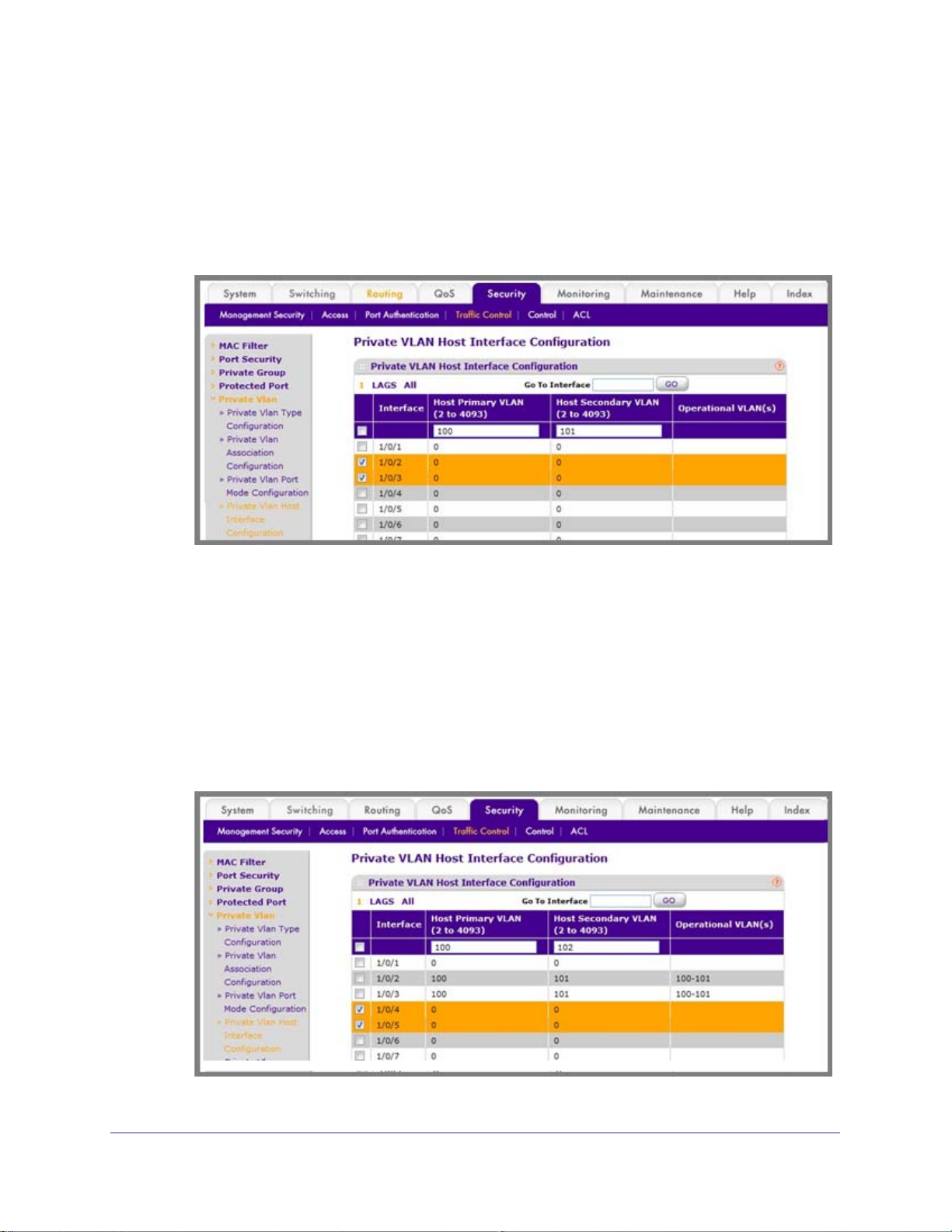
ProSafe M4100 and M7100 Managed Switches
Web Interface: Assign Private-VLAN Port Host Ports
1. Associate isolated ports 1/0/2-1/0/3 to a private-VLAN (primary=100, secondary=101).
a. Select Security > T
Configuration.
A screen similar to the following displays.
raffic Control > Private VLAN > Private VLAN Host Interface
b. Under Private VLAN Host Interface Configuration, select the 1/0/2 and 1/0/3
interface check box.
c. In the Host Primary VLAN field, enter 100.
d. In the Host Secondary VLAN field, enter 101.
e. Click Apply to save the settings.
2. Associate isolated ports 1/0/4-1/0/5 to a private-VLAN (primary=100, secondary=102).
a. Select Security > T
Configuration.
A screen similar to the following displays.
raffic Control > Private VLAN > Private VLAN Host Interface
Chapter 2. VLANs | 51
Page 52
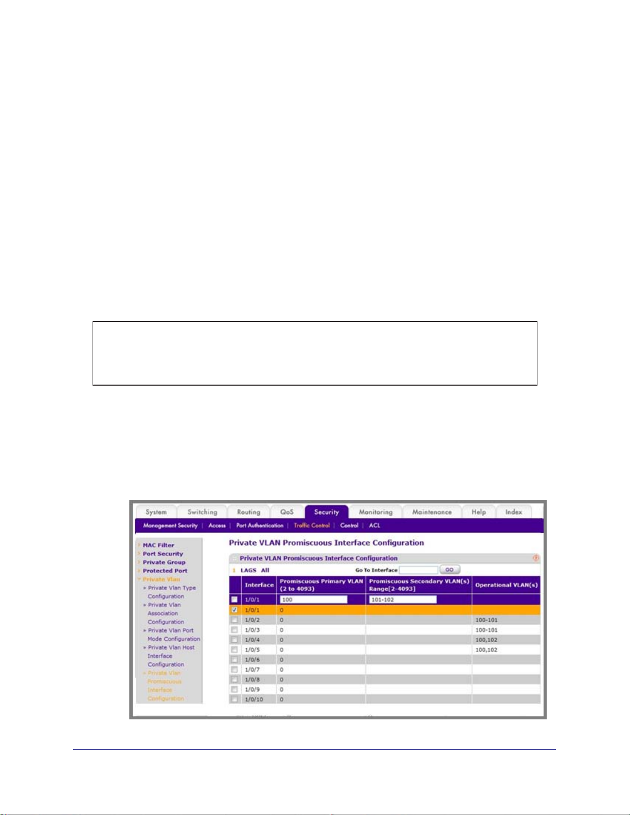
ProSafe M4100 and M7100 Managed Switches
b. Under Private VLAN Host Interface Configuration, select the 1/0/4 and 1/0/5
interface check box.
c. In the Host Primary VLAN field, enter 100.
d. In the Host Secondary VLAN field, enter 102.
e. Click Apply to save the settings.
Map Private-VLAN Promiscuous Port
The example is shown as CLI commands and as a Web interface procedure.
CLI: Map Private-VLAN Promiscuous Port
Use the following commands to map private-VLAN promiscuous port 1/0/1 to a primary VLAN
(100) and to secondary VLANs (101-102).
(Netgear Switch) #config
(Netgear Switch) (Config)#interface 1/0/1
(Netgear Switch) (Interface 1/0/1)#switchport private-vlan mapping 100 101-102
(Netgear Switch) (Interface 1/0/1)#end
Web Interface: Map Private-VLAN Promiscuous Port
1. 1.Map private-VLAN promiscuous port 1/0/1 to a primary VLAN (100) and to selected
secondary VLANs (101-102).
a. Select Security > T
Interface Configuration. A screen similar to the following displays.
raffic Control > Private VLAN > Private VLAN Promiscuous
52 | Chapter 2. VLANs
Page 53

ProSafe M4100 and M7100 Managed Switches
b. Under Private VLAN Promiscuous Interface Configuration, select the 1/0/1
interface check box. Now 1/0/1 appears in the Interface field at the top.
c. In the Promiscuous Primary VLAN field, enter 100.
d. In the Promiscuous Secondary VLAN field, enter 101-102.
e. Click Apply to save the settings.
Chapter 2. VLANs | 53
Page 54
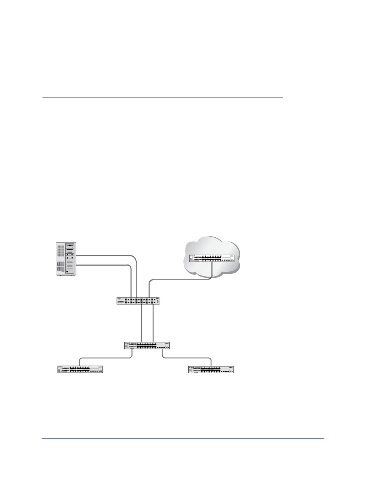
3. LAGs
Link Aggregation Groups
This chapter provides the following examples:
• Create Two LAGs on page 55
• Add Ports to LAGs on page 56
• Enable Both LAGs on page 59
Link aggregation allows the switch to treat multiple physical links between two endpoints as a
single logical link.
same speed. LAGs can be used to directly connect two switches when the traffic between them
requires high bandwidth and reliability, or to provide a higher-bandwidth connection to a public
network. Management functions treat a LAG as if it were a single physical port. You can include
a LAG in a VLAN. You can configure more than one LAG for a given switch.
Server
All the physical links in a given LAG must operate in full-duplex mode at the
Port 1/0/3
LAG_10
Subnet 3
Port 1/0/2
LAG_10
3
Layer 3 Switch
Port 1/0/8
LAG 20
Layer 2 Switch
Subnet 2 Subnet 3
Figure 6. Example network with two LAGs
LAGs offer the following benefits:
• Increased reliability and availability
traffic is dynamically and transparently reassigned to one of the other physical links.
Port 1/0/9
LAG_20
. If one of the physical links in the LAG goes down,
Chapter 3. LAG s | 54
Page 55
ProSafe M4100 and M7100 Managed Switches
• Better use of physical resources. Traffic can be load-balanced across the physical links.
• Increased bandwidth.
The aggregated physical links deliver higher bandwidth than each
individual link.
• Incremental increase in bandwidth.
A physical upgrade could produce a tenfold increase
in bandwidth; LAG produces a two- or fivefold increase, useful if only a small increase is
needed.
Create Two LAGs
The example is shown as CLI commands and as a Web interface procedure.
CLI: Create Two LAGs
(Netgear Switch) #config
(Netgear Switch) (Config)#port-channel name lag 1 lag_10
(Netgear Switch) (Config)#port-channel name lag 1 lag_20
(Netgear Switch) (Config)#exit
Use the show port-channel all command to show the logical interface IDs you will use to
identify the LAGs in subsequent commands. Assume that lag_10 is assigned ID 1/1, and
lag_20 is assigned ID 1/2.
(Console) #show port-channel all
Port- Link
Log. Channel Adm. Trap STP Mbr Port Port
Intf Name Link Mode Mode Mode Type Ports Speed Active
------ --------------- ------ ---- ---- ------ ------- ------ --------- -----1/1 lag_10 Down En. En. Dis. Dynamic
1/2 lag_20 Down En. En. Dis. Dynamic
Web Interface: Create Two LAGs
1. Create LAG lag_10.
a. Select Switching > LAG > LAG Configuration.
Chapter 3. LAG s | 55
Page 56
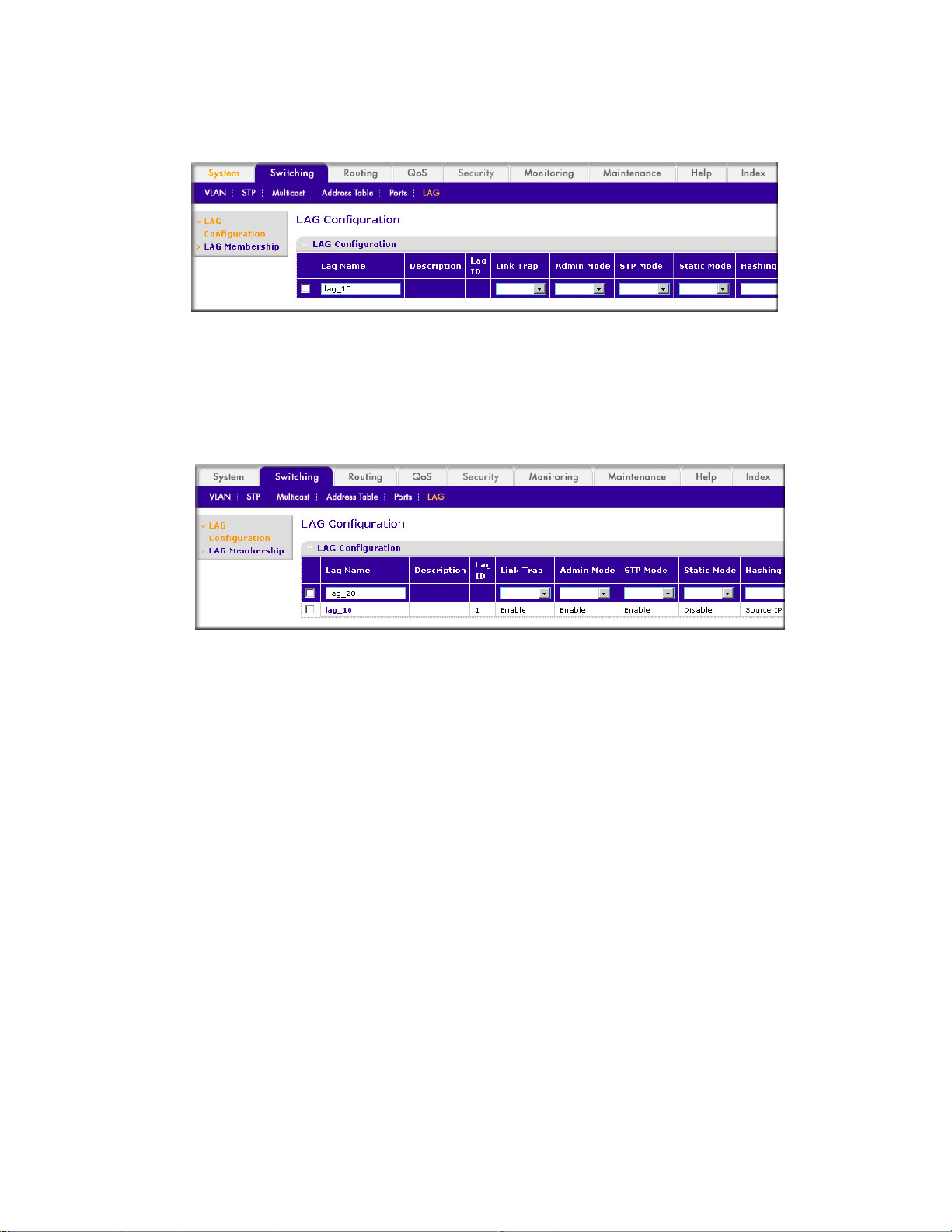
A screen similar to the following displays.
b. In the Lag Name field, enter lag_10.
c. Click Add.
2. Create LAG lag_20.
a. Select Switching > LAG > LAG Configuration.
displays.
ProSafe M4100 and M7100 Managed Switches
A screen similar to the following
b. In the Lag Name field, enter lag_20.
c. Click Add.
Add Ports to LAGs
The example is shown as CLI commands and as a Web interface procedure.
56 | Chapter 3. LAG s
Page 57

ProSafe M4100 and M7100 Managed Switches
CLI: Add Ports to the LAGs
(Netgear Switch) #config
(Netgear Switch) (Config)#interface 0/2
(Netgear Switch) (Interface 0/2)#addport 1/1
(Netgear Switch) (Interface 0/2)#exit
(Netgear Switch) (Config)#interface 0/3
(Netgear Switch) (Interface 0/3)#addport 1/1
(Netgear Switch) (Interface 0/3)#exit
(Netgear Switch) (Config)#interface 0/8
(Netgear Switch) (Interface 0/8)#addport 1/2
(Netgear Switch) (Interface 0/8)#exit
(Netgear Switch) (Config)#interface 0/9
(Netgear Switch) (Interface 0/9)#addport 1/2
(Netgear Switch) (Interface 0/9)#exit
(Netgear Switch) (Config)#exit
Chapter 3. LAG s | 57
Page 58

Web Interface: Add Ports to LAGs
1. Add ports to lag_10.
a. Select Switching > LAG > LAG Membership.
A screen similar to the following displays.
ProSafe M4100 and M7100 Managed Switches
b. In the LAG ID list, select LAG 1.
c. Click Unit 1. The ports display
d. Click the gray boxes under port 2 and 3.
Two check marks display in the box.
e. Click Apply to save the settings.
2. Add ports to lag_20.
a. Select Switching > LAG > LAG Membership.
A screen similar to the following displays.
.
b. Under LAG Membership, in the LAG ID list, select LAG 2.
c. Click Unit 1.
58 | Chapter 3. LAG s
The ports display.
Page 59

ProSafe M4100 and M7100 Managed Switches
d. Click the gray boxes under ports 8 and 9.
Two check marks display in the boxes.
e. Click Apply to save the settings.
Enable Both LAGs
The example is shown as CLI commands and as a Web interface procedure.
CLI: Enable Both LAGs
By default, the system enables link trap notification.
(Console) #config
(Console) (Config)#port-channel adminmode all
(Console) (Config)#exit
At this point, the LAGs could be added to VLANs.
Web Interface: Enable Both LAGs
a. Select Switching > LAG > LAG Configuration.
A screen similar to the following displays.
b. Select the top check box and the check boxes for lag_10 and lag_20 are selected.
c. In the Admin Mode field, select Enable.
d. Click Apply to save the settings.
Chapter 3. LAG s | 59
Page 60

4. Port Routing
This chapter provides the following sections:
• Port Routing Configuration on page 61
• Enable Routing for the Switch on page 62
• Enable Routing for Ports on the Switch on page 62
• Add a Default Route on page 65
• Add a Static Route on page 66
The first networks were small enough for the end stations to communicate directly. As networks
grew, Layer 2 bridging was used to segregate traffic, a technology that worked well for unicast
traffic, but had problems coping with large quantities of multicast packets. The next major
development was routing, where packets were examined and redirected at Layer 3. End stations
needed to know how to reach their nearest router, and the routers had to interpret the network
topology so that they could forward traffic. Although bridges tended to be faster than routers,
using routers allowed the network to be partitioned into logical subnetworks, which restricted
multicast traffic and also facilitated the development of security mechanisms.
4
An end station specifies the destination station’s Layer 3 address in the packet’s IP header, but
sends the packet to the MAC address of a router. When the Layer 3 router receives the packet, it
will minimally:
• Look up the Layer 3 address in its address table to determine the outbound port.
• Update the Layer 3 header.
• Re-create the Layer 2 header.
The router’s IP address is often statically configured in the end station, although the M4100 and
M7100 Managed Switch supports protocols such as DHCP that allow the address to be assigned
dynamically. Likewise, you can assign some of the entries in the routing tables used by the
router statically , but protocols such as RIP and OSPF allow the tables to be created and updated
dynamically as the network configuration changes.
Chapter 4. Port Routing | 60
Page 61

ProSafe M4100 and M7100 Managed Switches
Port Routing Configuration
The M4100 and M7100 Managed Switch always supports Layer 2 bridging, but Layer 3
routing must be explicitly enabled, first for the M4100 and M7100 Managed Switch as a
whole, and then for each port that is to be part of the routed network.
The configuration commands used in the example in this section enable IP routing on ports
1/0/2,1/0/3, and 1/0/5.
management IP address, or to that of any active router interface if the management address
is not configured.
After the routing configuration commands have been issued, the following functions will be
active:
• IP forwarding, responsible for forwarding received IP packets.
• ARP mapping, responsible for maintaining the
addresses. The table contains both static entries and entries dynamically updated based
on information in received ARP frames.
• Routing
Table Object, responsible for maintaining the common routing table used by all
registered routing protocols.
The router ID will be set to the M4100 and M7100 Managed Switch’s
ARP Table used to correlate IP and MAC
You can then activate RIP or OSPF, used by routers to exchange route information, on top of
IP Routing. RIP is more often used in smaller networks, while OSPF was designed for larger
and more complex topologies.
The following figure shows a Layer 3 switch configured for port routing. It connects three
ferent subnets, each connected to a different port.
dif
Layer 3 switch
acting as a router
Port 1/0/2
192.150.2.2
Port 1/0/3
192.130.3.1
Port 1/0/5
192.64.4.1
Subnet 2 Subnet 3 Subnet 5
Figure 7. Layer 3 switch configured for port routing
Chapter 4. Port Routing | 61
Page 62

ProSafe M4100 and M7100 Managed Switches
Enable Routing for the Switch
The example is shown as CLI commands and as a Web interface procedure.
CLI: Enable Routing for the Switch
The following script shows the commands that you would use to configure a M4100 and
M7100 Managed Switch to provide the port routing support shown in Figure 7, Layer 3 switch
configured for port routing on page 61.
Use the following command to enable routing for the switch. Execution of the command
enables IP forwarding by default.
(Netgear Switch) #config
(Netgear Switch) (Config)#ip routing
(Netgear Switch) (Config)#exit
Web Interface: Enable Routing for the Switch
1. Select Routing > IP > Basic > IP Configuration.
A screen similar to the following displays.
2. For Routing Mode, select the Enable radio button.
3. Click Apply to save the settings.
Enable Routing for Ports on the Switch
Use the following commands or the web interface to enable routing for ports on the switch.
The default link-level encapsulation format is Ethernet. Configure the IP addresses and
subnet masks for the ports. Network-directed broadcast frames will be dropped. The
maximum transmission unit (MTU) size is 1500 bytes.
62 | Chapter 4. Port Routing
Page 63

ProSafe M4100 and M7100 Managed Switches
CLI: Enable Routing for Ports on the Switch
(Netgear Switch) #config
(Netgear Switch) (Config)#interface 1/0/2
(Netgear Switch) (Interface 1/0/2)#routing
(Netgear Switch) (Interface 1/0/2)#ip address 192.150.2.1 255.255.255.0
(Netgear Switch) (Interface 1/0/2)#exit
(Netgear Switch) (Config)#interface 1/0/3
(Netgear Switch) (Interface 1/0/3)#routing
(Netgear Switch) (Interface 1/0/3)#ip address 192.150.3.1 255.255.255.0
(Netgear Switch) (Interface 1/0/3)#exit
(Netgear Switch) (Config)#interface 1/0/5
(Netgear Switch) (Interface 1/0/5)#routing
(Netgear Switch) (Interface 1/0/5)#ip address 192.150.5.1 255.255.255.0
(Netgear Switch) (Interface 1/0/5)#exit
(Netgear Switch) (Config)#exit
Web Interface: Enable Routing for Ports on the Switch
1. Assign IP address 192.150.2.1/24 to interface 1/0/2.
a. Select Routing > IP >
A screen similar to the following displays.
b. Scroll down and select the interface 1/0/2 check box.
Now 1/0/2 appears in the Interface field at the top.
c. Under the IP Interface Configuration, enter the following information:
• In the IP Address field, enter 192.150.2.1.
• In the Subnet Mask field, enter 255.255.255.0.
• In the Routing Mode field, select Enable.
Advanced > IP Interface Configuration.
Chapter 4. Port Routing | 63
Page 64
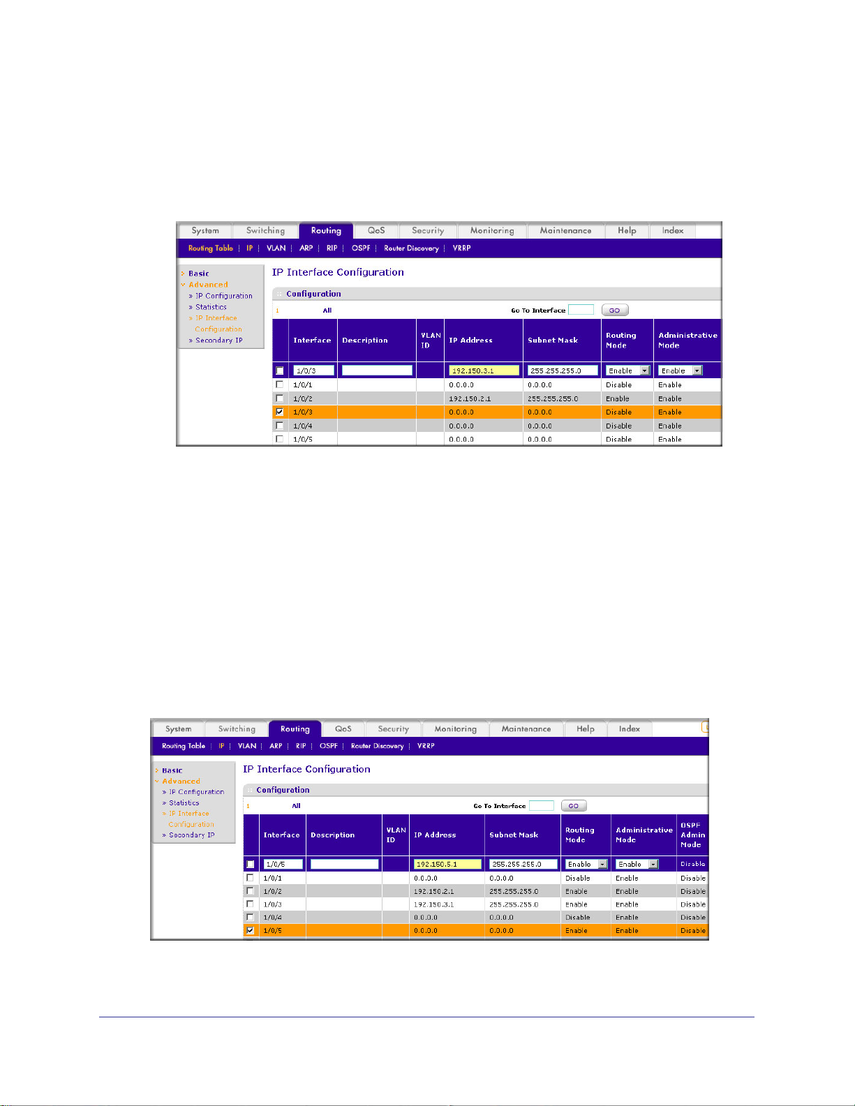
ProSafe M4100 and M7100 Managed Switches
d. Click Apply to save the settings.
2. Assign IP address 192.150.3.1/24 to interface 1/0/3.
a. Select Routing > IP>
Advanced > IP Interface Configuration.
A screen similar to the following displays.
b. Scroll down and select the interface 1/0/3 check box.
Now 1/0/3 appears in the Interface field at the top.
c. Enter the following information:
• In the IP Address field, enter 192.150.3.1.
• In the Subnet Mask field, enter 255.255.255.0.
• In the Routing Mode field, select Enable.
d. Click Apply to save the settings.
3. Assign IP address 192.150.5.1/24 to interface 1/0/5.
a. Select Routing > IP >
Advanced > IP Interface Configuration.
A screen similar to the following displays.
b. Scroll down and select the interface 1/0/5 check box.
64 | Chapter 4. Port Routing
Page 65

ProSafe M4100 and M7100 Managed Switches
Now 1/0/5 appears in the Interface field at the top.
c. Enter the following information:
• In the IP Address field, enter 192.150.5.1.
• In the Subnet Mask field, enter 255.255.255.0.
• In the Routing Mode field, select Enable.
d. Click Apply to save the settings.
Add a Default Route
When IP routing takes place on a switch, a routing table is needed for the switch to forward
the packet based on the destination IP address. The route entry in the routing table can
either be created dynamically through routing protocols like RIP and OSPF, or be manually
created by the network administrator. The route created manually is called the static or
default route.
A default route is used for forwarding the packet when the switch cannot find a match in the
routing table for an IP packet.
The following example shows how to create a default route.
CLI: Add a Default Route
(FSM7338S) (Config) #ip route default?
<nexthopip> Enter the IP Address of the next router.
(FSM7328S) (Config)#ip route default 10.10.10.2
Note: IP subnet 10.10.10.0 should be configured using either port routing
(Enable Routing for Ports on the Switch on page 62) or VLAN
routing (see Set Up VLAN Routing for the VLANs and the Switch on
page 73).
Web Interface: Add a Default Route
1. Select Routing > Routing Table > Basic > Route Configuration.
Chapter 4. Port Routing | 65
Page 66
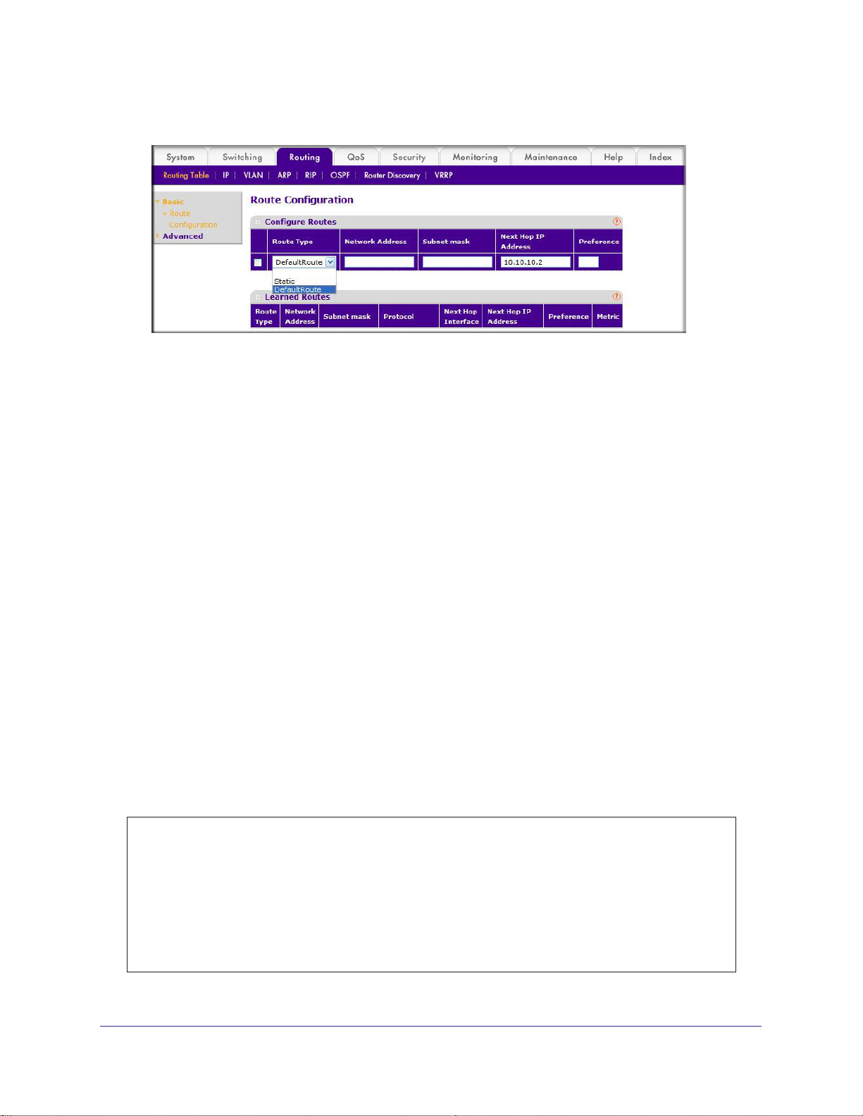
ProSafe M4100 and M7100 Managed Switches
The Route Configuration screen displays.
2. In the Route Type list, select DefaultRoute.
3. In the Next Hop IP
Address field, enter one of the routing interface’s IP addresses.
• The Network Address and Subnet Mask fields will not accept input as they are not
needed.
• The Preference field is optional.
A value of 1 (highest) will be assigned by default if
not specified.
4. Click the Add button on the bottom of the screen.
This creates the default route entry in the routing table.
Add a Static Route
When the switch performs IP routing, it forwards the packet to the default route for a
destination that is not in the same subnet as the source address. However, you can set a
path (static route) that is different than the default route if you prefer . The following procedure
shows how to add a static route to the switch routing table.
CLI: Add a Static Route
The following commands assume that the switch already has a defined a routing interface
with a network address of 10.10.10.0, and is configured so that all packets destined for
network 10.10.100.0 take the path of routing port.
(FSM7328S) #show ip route
Total Number of Routes............................1
Network Subnet Next Hop Next Hop
AddressMaskProtocolIntfIP Address
--------------- --------------- --------------- --------------- ---------------
10.10.10.0 255.255.255.0 Local 1/0/3 10.10.10.1
66 | Chapter 4. Port Routing
Page 67
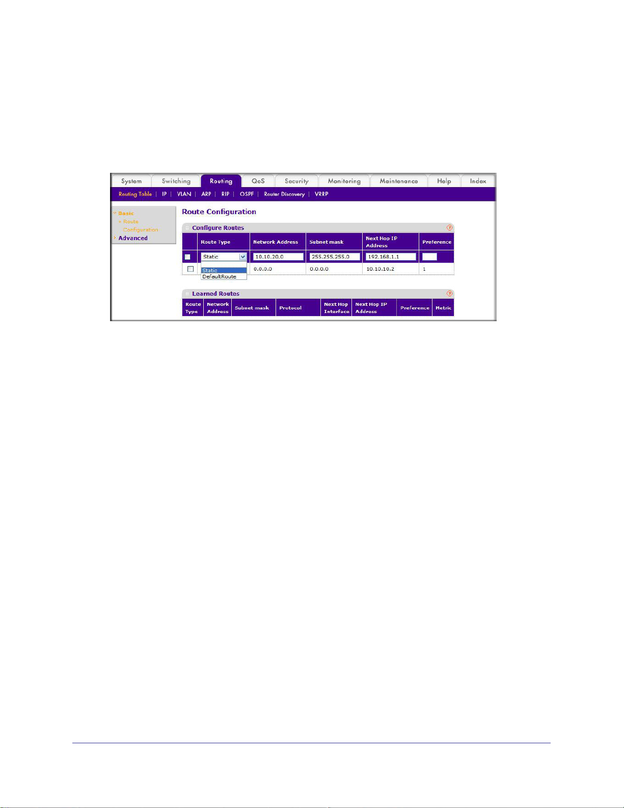
ProSafe M4100 and M7100 Managed Switches
To delete the static route, simply add “no” keyword in the front of the “ip route” command.
Web Interface: Add a Static Route
1. Select Routing > Routing Table > Basic > Route Configuration to display the Route
Configuration screen.
2. In the Route Type list, select Static.
3. Fill in the Network Address field.
Note that this field should have a network IP address, not a host IP address. Do not enter
something like 10,100.100.1.
4. In the Subnet Mask field, enter a value that matches the subnet range that you want to use.
5. The Preference field is optional.
number.
6. Click the Add button on the bottom of the screen.
route shown in the routing table.
7. T
o remove a route entry, either static or default, select the check box to the left of the entry,
and click the Delete button on the bottom of the screen.
The last number should always be 0 (zero).
A value of 1 is entered by default if you do not enter a
The screen is updated with the static
Chapter 4. Port Routing | 67
Page 68

5. VLAN Routing
This chapter provides the following examples:
• Create Two VLANs on page 68
• Set Up VLAN Routing for the VLANs and the Switch on page 73
You can configure the M4100 and M7100 Managed Switch with some ports supporting VLANs
and some supporting routing. You can also configure it to allow traffic on a VLAN to be treated as
if the VLAN were a router port.
When a port is enabled for bridging (the default) rather than routing, all normal bridge processing
is performed for an inbound packet, which is then associated with a VLAN. Its MAC destination
address (DA) and VLAN ID are used to search the MAC address table. If routing is enabled for
the VLAN and the MAC DA of an inbound unicast packet is that of the internal bridge-router
interface, the packet is routed. An inbound multicast packet is forwarded to all ports in the VLAN,
and also to the internal bridge-router interface if it was received on a routed VLAN.
Since a port can be configured to belong to more than one VLAN, VLAN routing might be
enabled for all of the VLANs on the port, or for a subset. VLAN routing can be used to allow more
than one physical port to reside on the same subnet. It could also be used when a VLAN spans
multiple physical networks, or when more segmentation or security is required.
5
The next section shows you how to configure the M4100 and M7100 Managed Switch to support
VLAN routing and how to use RIP and OSPF. A port can be either a VLAN port or a router port,
but not both. However, a VLAN port can be part of a VLAN that is itself a router port.
Create Two VLANs
This section provides an example of how to configure the M4100 and M7100 Managed
Switch to support VLAN routing. The configuration of the VLAN router port is similar to that of
a physical port. The main difference is that, after the VLAN has been created, you must use
the show ip vlan command to determine the VLAN’s interface ID so that you can use it in the
router configuration commands.
The diagram in this section shows a Layer 3 switch configured for port routing. It connects
two VLANs, with two ports participating in one VLAN, and one port in the other. The script
Chapter 5. VLAN Routing | 68
Page 69
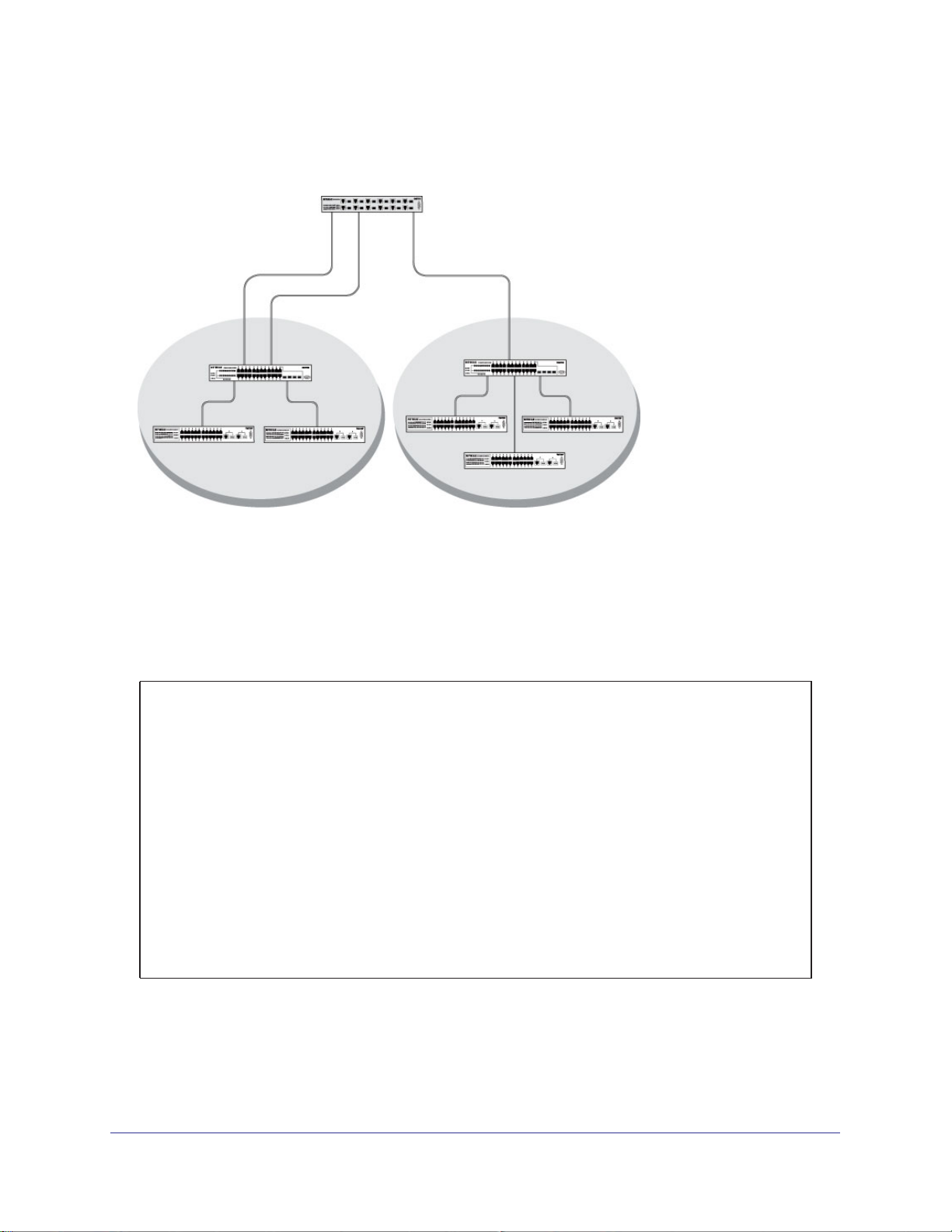
ProSafe M4100 and M7100 Managed Switches
shows the commands that you would use to configure a M4100 and M7100 Managed Switch
to provide the VLAN routing support shown in the diagram.
Layer 3 switch
Port 1/0/2 VLAN
Router port 1/3/1
192.150.3.1
Port 1/0/1
Layer 2
Switch
VLAN 10 VLAN 20
Port 1/0/3 VLAN
Router port 1/3/2
192.150.4.1
Layer 2
Switch
Figure 8. Layer 3 switch configured for port routing
CLI: Create Two VLANs
The following code sequence shows an example of creating two VLANs with egress frame
tagging enabled.
(Netgear Switch) #vlan data
(Netgear Switch) (Vlan)#vlan 10
(Netgear Switch) (Vlan)#vlan 20
(Netgear Switch) (Vlan)#exit
(Netgear Switch) #conf
(Netgear Switch) (Config)#interface range 1/0/1-1/0/2
(Netgear Switch) (conf-if-range-1/0/1-1/0/2)#vlan participation include 10
(Netgear Switch) (conf-if-range-1/0/1-1/0/2)#vlan pvid 10
(Netgear Switch) (conf-if-range-1/0/1-1/0/2)#exit
(Netgear Switch) (Config)#interface 1/0/3
(Netgear Switch) (Interface 1/0/3)#vlan participation include 20
(Netgear Switch) (Interface 1/0/3)#vlan pvid 20
(Netgear Switch) (Interface 1/0/3)#exit
(Netgear Switch) (Config)#exit
Chapter 5. VLAN Routing | 69
Page 70
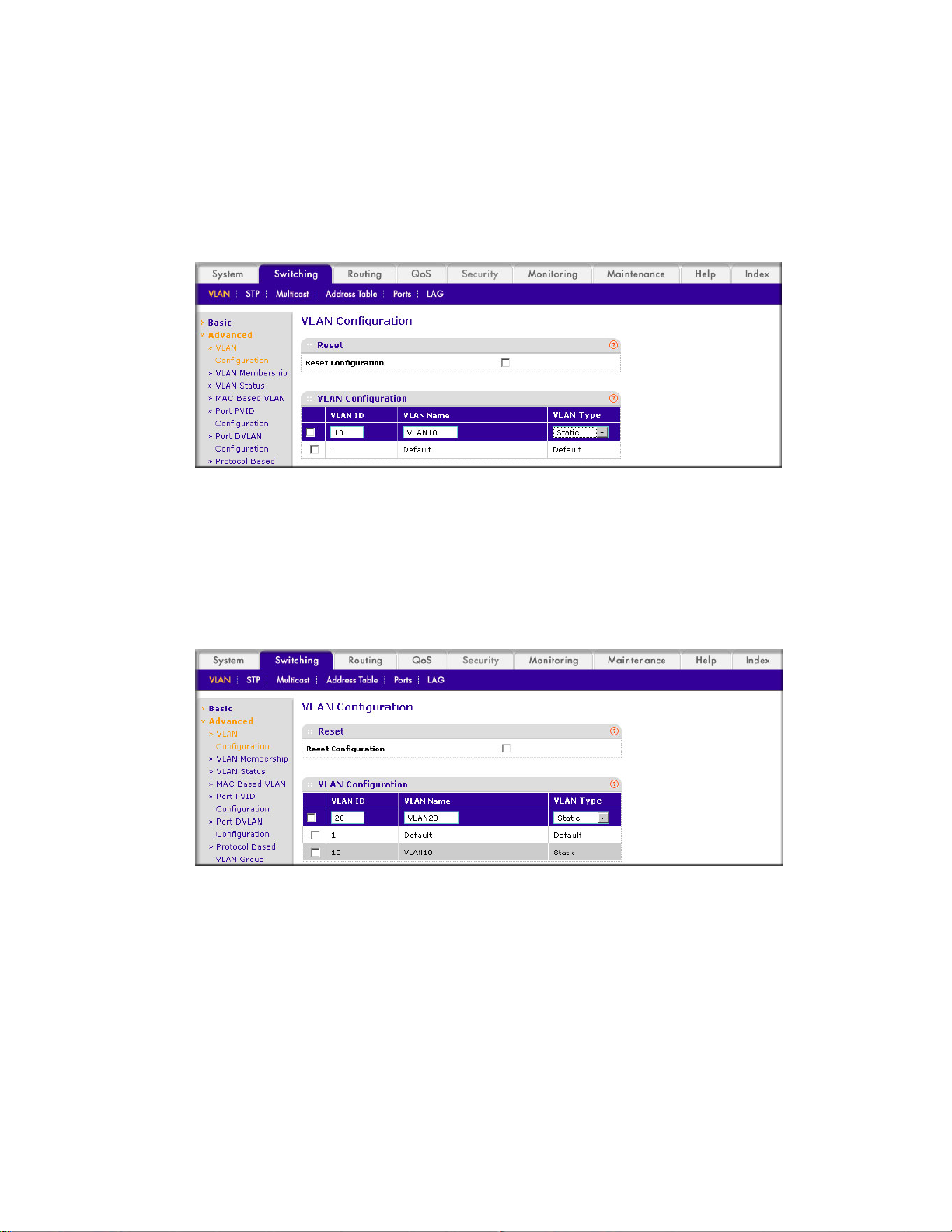
Web Interface: Create Two VLANs
1. Create VLAN 10 and VLAN20.
a. Select Switching > VLAN >
A screen similar to the following displays.
b. In the VLAN ID field, enter 10.
c. In the VLAN Name field, enter VLAN10.
d. In the VLAN T
e. Click Add.
f. Select Switching > VLAN >
ype list, select Static.
Advanced > VLAN Configuration.
Advanced > VLAN Configuration.
ProSafe M4100 and M7100 Managed Switches
A screen similar to the following displays.
g. In the VLAN ID field, enter 20.
h. In the VLAN Name field, enter VLAN20.
i. In the VLAN T
j. Click Add.
2. Add ports to the VLAN10 and VLAN20.
a. Select Switching > VLAN >
ype list, select Static.
Advanced > VLAN Membership.
70 | Chapter 5. VLAN Routing
Page 71

ProSafe M4100 and M7100 Managed Switches
A screen similar to the following displays.
b. In the VLAN ID field, select 10.
c. Click the Unit 1. The ports display
d. Click the gray boxes under ports 1 and 2 until T displays.
The T specifies that the egress packet is tagged for the port.
.
e. Click Apply.
f. Select Switching > VLAN >
Advanced > VLAN Membership.
A screen similar to the following displays.
g. In the VLAN ID list, select 20.
h. Click Unit 1. The ports display
.
i. Click the gray box under port 3 until T displays.
The T specifies that the egress packet is tagged for the port.
j. Click Apply.
3. Assign PVID to VLAN10 and VLAN20.
a. Select Switching > VLAN >
Advanced > Port PVID Configuraton.
Chapter 5. VLAN Routing | 71
Page 72
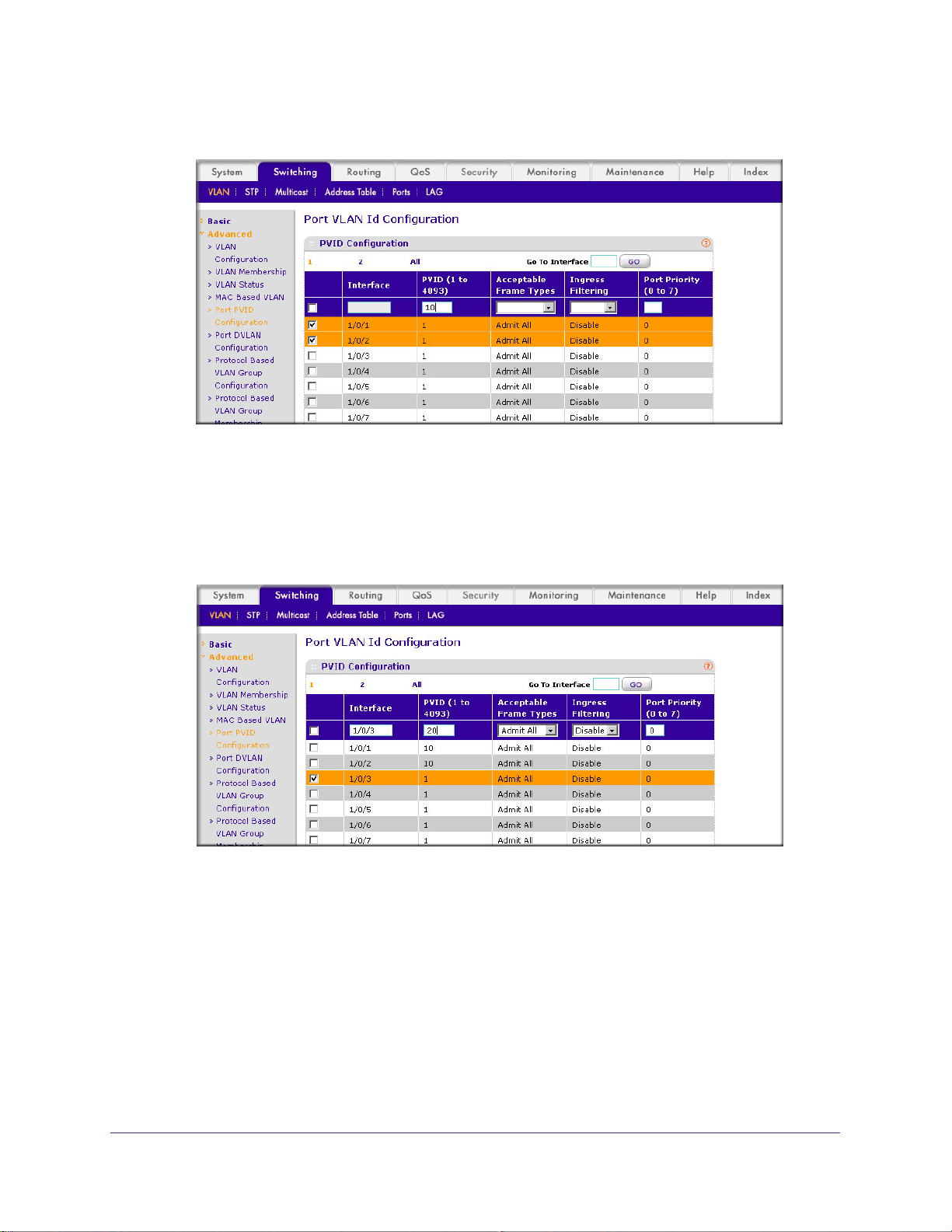
ProSafe M4100 and M7100 Managed Switches
A screen similar to the following displays.
b. Scroll down and select 1/0/1 and 1/0/2 check boxes.
c. In the PVID (1 to 4093) field, enter 10.
d. Click Apply to save the settings.
e. Select Switching > VLAN >
Advanced > Port PVID Configuraton.
A screen similar to the following displays.
f. Scroll down and select the 1/0/3 check box.
g. In the PVID (1 to 4093) field, enter 20.
h. Click Apply to save the settings.
72 | Chapter 5. VLAN Routing
Page 73

ProSafe M4100 and M7100 Managed Switches
Set Up VLAN Routing for the VLANs and the Switch
The example is shown as CLI commands and as a Web interface procedure.
CLI: Set Up VLAN Routing for the VLANs and the Switch
1. The following code sequence shows how to enable routing for the VLANs:
(Netgear Switch) #vlan data
(Netgear Switch) (Vlan)#vlan routing 10
(Netgear Switch) (Vlan)#vlan routing 20
(Netgear Switch) (Vlan)#exit
This returns the logical interface IDs that will be used instead of the slot/port in
subsequent routing commands. Assume that VLAN 10 is assigned the ID 3/1, and VLAN
20 is assigned the ID 3/2.
2. Enable routing for the switch.
(Netgear Switch) #config
(Netgear Switch) (Config)#ip routing
(Netgear Switch) (Config)#exit
3. The next sequence shows an example of configuring the IP addresses and subnet masks
for the virtual router ports.
(Netgear Switch) (Config)#interface vlan 10
(Netgear Switch) (Interface-vlan 10)#ip address 192.150.3.1 255.255.255.0
(Netgear Switch) (Interface-vlan 10)#exit
(Netgear Switch) (Config)#interface vlan 20
(Netgear Switch) (Interface-vlan 20)#ip address 192.150.4.1 255.255.255.0
(Netgear Switch) (Interface-vlan 20)#exit
(Netgear Switch) (Config)#exit
Web Interface: Set Up VLAN Routing for the VLANs and the Switch
1. Select Routing > VLAN> VLAN Routing.
Chapter 5. VLAN Routing | 73
Page 74

A screen similar to the following displays.
2. Enter the following information:
• In the VLAN ID (1 to 4093) list, select 10.
• In the IP Address field, enter 192.150.3.1.
• In the Subnet Mask field, enter 255.255.255.0.
3. Click Add to save the settings.
4. Select Routing > VLAN > VLAN Routing.
ProSafe M4100 and M7100 Managed Switches
A screen similar to the following displays.
5. Enter the following information:
• Select 10 in the VLAN ID (1 to 4093) field.
• In the IP Address field, enter 192.150.4.1.
• In the Subnet Mask field, enter 255.255.255.0.
6. Click Add to save the settings.
74 | Chapter 5. VLAN Routing
Page 75

6. RIP
Routing Information Protocol
This chapter provides the following examples:
• Routing for the Switch on page 76
• Routing for Ports on page 77
• RIP for the Switch on page 78
• RIP for Ports 1/0/2 and 1/0/3 on page 79
• VLAN Routing with RIP on page 82
Routing Information Protocol (RIP) is a protocol that routers can use to exchange network
topology information. It is characterized as an interior gateway protocol, and is typically used in
small to medium-sized networks. A router running RIP sends the contents of its routing table to
each of its adjacent routers every 30 seconds. When a route is removed from the routing table, it
is flagged as unusable by the receiving routers after 180 seconds, and removed from their tables
after an additional 120 seconds.
There are two versions of RIP (the managed switch supports both):
• RIPv1 defined in RFC 1058.
- Routes are specified by IP destination network and hop count.
- The routing table is broadcast to all stations on the attached network.
• RIPv2 defined in RFC 1723.
- Route specification also includes subnet mask and gateway.
- The routing table is sent to a multicast address, reducing network traffic.
- Authentication is used for security.
6
You can configure a given port to do the following:
• Receive packets in either or both formats.
• Send packets formatted for RIPv1 or RIPv2, or send RIPv2 packets to the RIPv1
broadcast address.
• Prevent any RIP packets from being received.
• Prevent any RIP packets from being sent.
Chapter 6. RIP | 75
Page 76

Layer 3 sIwitch
acting as a router
ProSafe M4100 and M7100 Managed Switches
Port 1/0/2
192.150.2.2
Port 1/0/3
192.130.3.1
Subnet 2 Subnet 3 Subnet 5
Figure 9. Network with RIP on ports 1/0/2 and 1/0/3
Port 1/0/5
192.64.4.1
Routing for the Switch
The example is shown as CLI commands and as a Web interface procedure.
CLI: Enable Routing for the Switch
(Netgear Switch) #config
(Netgear Switch) (Config)#ip routing
(Netgear Switch) (Config)#exit
Web Interface: Enable Routing for the Switch
1. Select Routing > IP > Basic > IP Configuration.
A screen similar to the following displays.
2. For Routing Mode, select the Enable radio button.
76 | Chapter 6. RIP
Page 77

ProSafe M4100 and M7100 Managed Switches
3. Click Apply to save the settings.
Routing for Ports
The example is shown as CLI commands and as a Web interface procedure.
CLI: Enable Routing and Assigning IP Addresses for Ports 1/0/2 and 1/0/3
(Netgear Switch) #config
(Netgear Switch) (Config)#interface 1/0/2
(Netgear Switch) (Interface 1/0/2)#routing
(Netgear Switch) (Interface 1/0/2)#ip address 192.150.2.1 255.255.255.0
(Netgear Switch) (Interface 1/0/2)#exit
(Netgear Switch) (Config)#interface 1/0/3
(Netgear Switch) (Interface 1/0/3)#routing
(Netgear Switch) (Interface 1/0/3)#ip address 192.150.3.1 255.255.255.0
(Netgear Switch) (Interface 1/0/3)#exit
(Netgear Switch) (Config)#exit
Web Interface: Enable Routing for the Ports
1. Assign IP address 192.150.2.1/24 to interface 1/0/2.
a. Select Routing >
A screen similar to the following displays.
b. Scroll down and select the Interface 1/0/2 check box. Now 1/0/2 appears in the
Interface field at the top.
c. Enter the following information:
• In the IP Address field, enter 192.150.2.1.
• In the Subnet Mask field, enter 255.255.255.0.
Advanced > IP Interface Configuration.
Chapter 6. RIP | 77
Page 78

ProSafe M4100 and M7100 Managed Switches
• In the Routing Mode field, select Enable.
d. Click Apply to save the settings.
2. Assign IP address 192.150.3.1/24 to interface 1/0/3.
a. Select Routing >
A screen similar to the following displays.
Advanced >IP Interface Configuration.
b. Scroll down and select the interface 1/0/3 check box.
Now 1/0/3 appears in the Interface field at the top.
c. Enter the following information:
• In the IP Address field, enter 192.150.3.1.
• In the Subnet Mask field, enter 255.255.255.0.
• In the Routing Mode field, select Enable.
d. Click Apply to save the settings.
RIP for the Switch
Note: Unless you have previously disabled RIP, you can skip this step
since RIP is enabled by default.
78 | Chapter 6. RIP
Page 79

ProSafe M4100 and M7100 Managed Switches
CLI: Enable RIP on the Switch
This sequence enables RIP for the switch. The route preference defaults to 15.
(Netgear Switch) #config
(Netgear Switch) (Config)#router rip
(Netgear Switch) (Config router)#enable
(Netgear Switch) (Config router)#exit
(Netgear Switch) (Config)#exit
Web Interface: Enable RIP on the Switch
1. Select Routing > RIP > Basic > RIP Configuration.
A screen similar to the following displays.
2. For RIP Admin Mode, select Enable radio button.
3. Click Apply to save the setting.
RIP for Ports 1/0/2 and 1/0/3
The example is shown as CLI commands and as a Web interface procedure.
Chapter 6. RIP | 79
Page 80
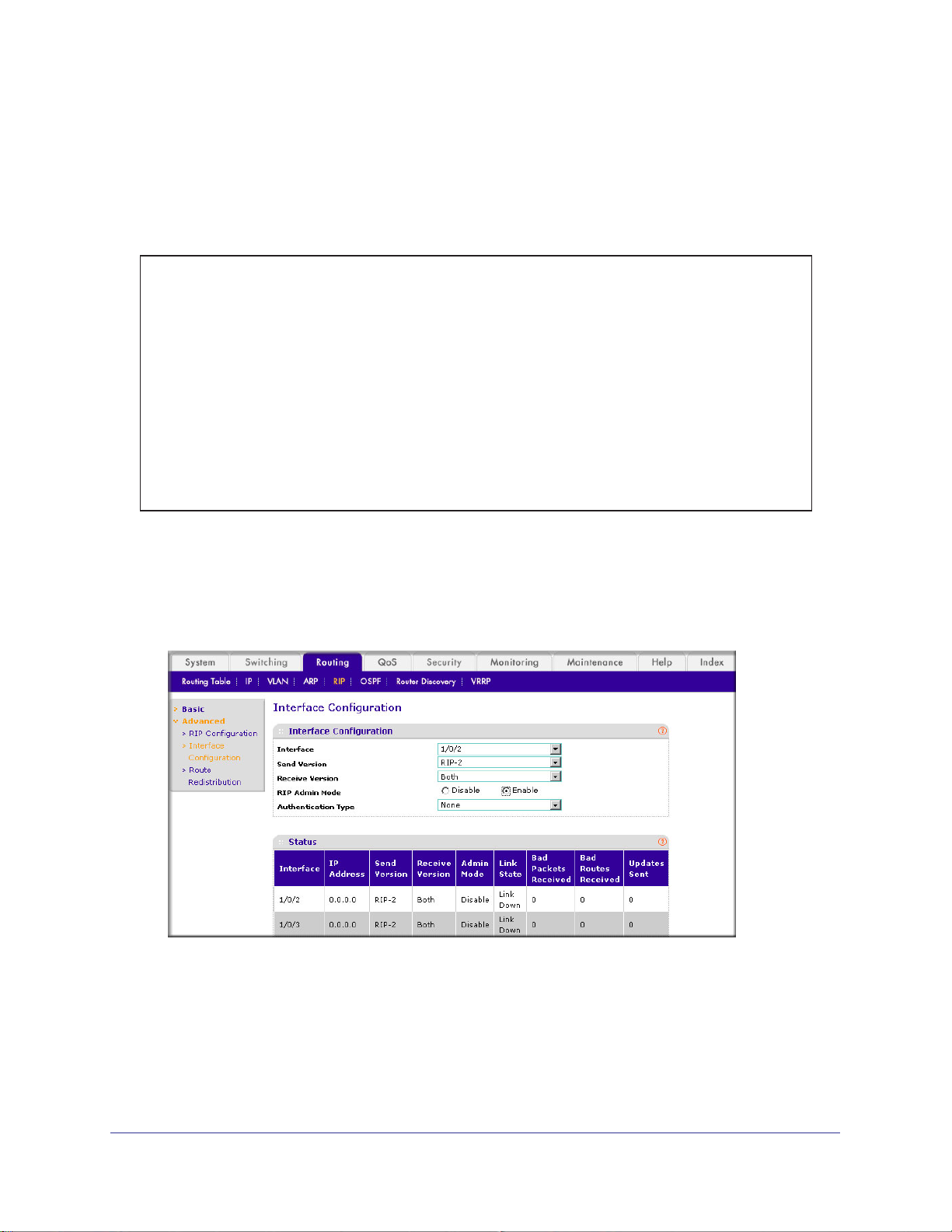
ProSafe M4100 and M7100 Managed Switches
CLI: Enable RIP for Ports 1/0/2 and 1/0/3
This command sequence enables RIP for ports 1/0/2 and 1/0/3. Authentication defaults to
none, and no default route entry is created. The commands specify that both ports receive
both RIPv1 and RIPv2 frames, but send only RIPv2-formatted frames.
(Netgear Switch) #config
(Netgear Switch) (Config)#interface 1/0/2
(Netgear Switch) (Interface 1/0/2)#ip rip
(Netgear Switch) (Interface 1/0/2)#ip rip receive version both
(Netgear Switch) (Interface 1/0/2)#ip rip send version rip2
(Netgear Switch) (Interface 1/0/2)#exit
(Netgear Switch) (Config)#interface 1/0/3
(Netgear Switch) (Interface 1/0/3)#ip rip
(Netgear Switch) (Interface 1/0/3)#ip rip receive version both
(Netgear Switch) (Interface 1/0/3)#ip rip send version rip2
(Netgear Switch) (Interface 1/0/3)#exit
(Netgear Switch) (Config)#exit
Web Interface: Enable RIP for Ports 1/0/2 and 1/0/3
1. Select Routing > RIP > Advanced > RIP Configuration.
A screen similar to the following displays.
2. Enter the following information:
• In the Interface field, select 1/0/2.
• For RIP Admin Mode, select the Enable radio button.
• In the Send V
ersion field, select RIP-2.
3. Click Apply to save the settings.
80 | Chapter 6. RIP
Page 81
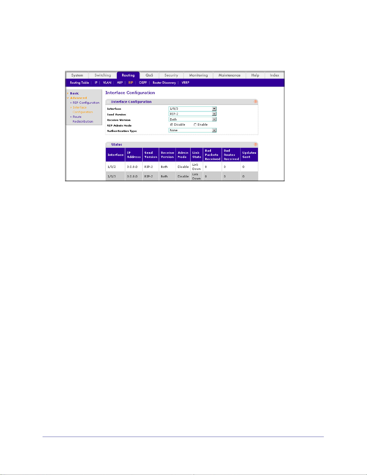
ProSafe M4100 and M7100 Managed Switches
4. Select Routing > RIP > Advanced > RIP Configuration.
A screen similar to the following displays.
5. Enter the following information:
• In the Interface field, select 1/0/3.
• For RIP Admin Mode, select the Enable radio button.
• In the Send V
ersion list, select RIP-2.
6. Click Apply to save the settings.
Chapter 6. RIP | 81
Page 82
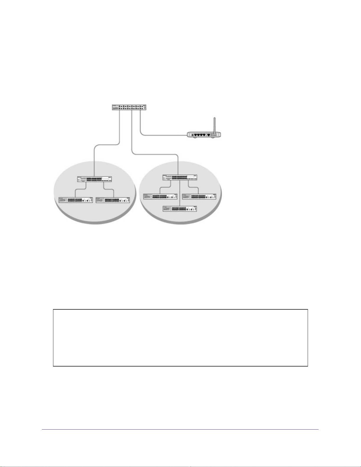
ProSafe M4100 and M7100 Managed Switches
VLAN Routing with RIP
Routing Information Protocol (RIP) is one of the protocols that routers can use to exchange
network topology information. It is characterized as an interior gateway protocol, and is
typically used in small to medium-sized networks.
Layer 3 switch
Port 1/0/2 VLAN
Router port 1/3/1
192.150.3.1
Layer 2
switch
VLAN 10 VLAN 20
Router port 1/0/5
192.150.4.1
Port 1/0/3 VLAN
Router port 1/3/2
192.150.4.1
Layer 2
switch
Router
Figure 10. VLAN routing RIP configuration example
This example adds support for RIPv2 to the configuration created in the base VLAN routing
example. A second router, using port routing rather than VLAN routing, has been added to
the network.
CLI: Configure VLAN Routing with RIP Support
1. Configure VLAN routing with RIP support on a M4100 and M7100 Managed Switch.
(Netgear Switch) #vlan data
(Netgear Switch) (Vlan)#vlan 10
(Netgear Switch) (Vlan)#vlan 20
(Netgear Switch) (Vlan)#vlan routing 10
(Netgear Switch) (Vlan)#vlan routing 20
(Netgear Switch) (Vlan)#exit
(Netgear Switch) #conf
82 | Chapter 6. RIP
Page 83

ProSafe M4100 and M7100 Managed Switches
(Netgear Switch) (Config)#ip routing
(Netgear Switch) (Config)#vlan port tagging all 10
(Netgear Switch) (Config)#vlan port tagging all 20
(Netgear Switch) (Config)#interface 1/0/2
(Netgear Switch) (Interface 1/0/2)#vlan participation include 10
(Netgear Switch) (Interface 1/0/2)#vlan pvid 10
(Netgear Switch) (Interface 1/0/2)#exit
(Netgear Switch) (Config)#interface 1/0/3
(Netgear Switch) (Interface 1/0/3)#vlan participation include 20
(Netgear Switch) (Interface 1/0/3)#vlan pvid 20
(Netgear Switch) (Interface 1/0/3)#exit
(Netgear Switch) #config
(Netgear Switch) (Config)#interface vlan 10
(Netgear Switch) (Interface vlan 10)#ip address 192.150.3.1 255.255.255.0
(Netgear Switch) (Interface vlan 10)#exit
(Netgear Switch) (Config)#interface vlan 20
(Netgear Switch) (Interface vlan 20)#ip address 192.150.4.1 255.255.255.0
(Netgear Switch) (Interface vlan 20)#exit
2. Enable RIP for the switch.
The route preference defaults to 15.
(Netgear Switch) (Config)#router rip
(Netgear Switch) (Config router)#enable
(Netgear Switch) (Config router)#exit
3. Configure the IP address and subnet mask for a nonvirtual router port.
(Netgear Switch) (Config)#interface 1/0/5
(Netgear Switch) (Interface 1/0/5)#ip address 192.150.5.1 255.255.255.0
(Netgear Switch) (Interface 1/0/5)#exit
4. Enable RIP for the VLAN router ports.
Authentication defaults to none, and no default route entry is created.
(Netgear Switch) (Config)#interface vlan 10
(Netgear Switch) (Interface vlan 10)#ip rip
(Netgear Switch) (Interface vlan 10)#exit
(Netgear Switch) (Config)#interface vlan 20
(Netgear Switch) (Interface vlan 20)#ip rip
(Netgear Switch) (Interface vlan 20)#exit
(Netgear Switch) (Config)#exit
Chapter 6. RIP | 83
Page 84
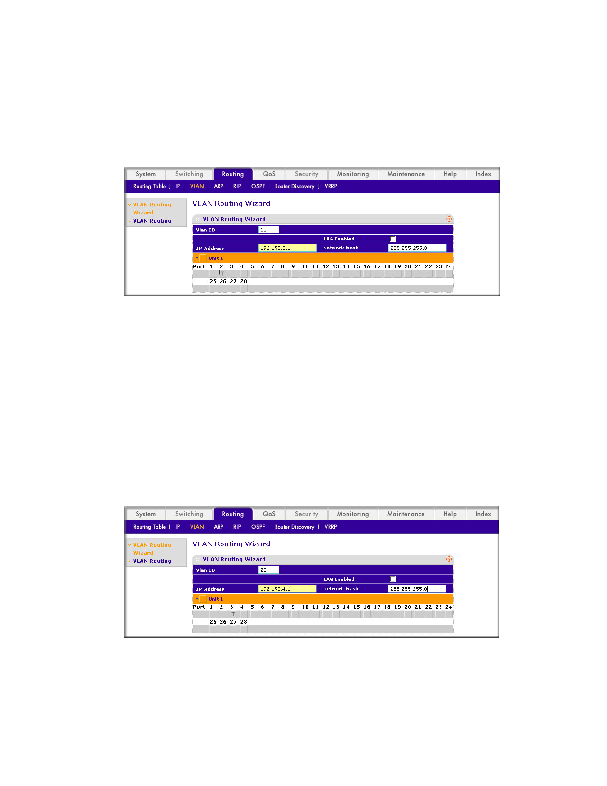
ProSafe M4100 and M7100 Managed Switches
Web Interface: Configure VLAN Routing with RIP Support
1. Configure a VLAN and include ports 1/0/2 in the VLAN:
a. Select Routing > VLAN > VLAN Routing W
A screen similar to the following displays.
izard.
b. Enter the following information:
• In the VLAN ID field, enter 10.
• In the IP Address field, enter 192.150.3.1.
• In the Network Mask field, enter 255.255.255.0.
c. Click Unit 1.
d. Click the gray box under port 2 until T displays.
The T specifies that the egress packet is tagged for the port.
e. Click Apply to save the VLAN that includes ports 2.
2. Configure a VLAN, and include port 1/0/3 in the VLAN:
a. Select Routing > VLAN > VLAN Routing W
A screen similar to the following displays.
The ports display:
izard.
b. Enter the following information:
• In the Vlan ID field, enter 20.
• In the IP Address field, enter 192.150.4.1.
84 | Chapter 6. RIP
Page 85
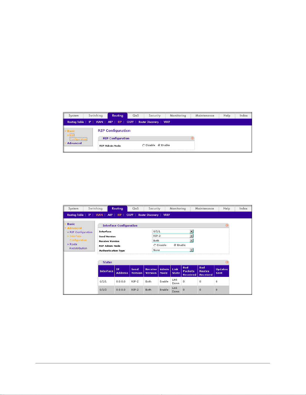
ProSafe M4100 and M7100 Managed Switches
• In the Network Mask field, enter 255.255.255.0.
c. Click Unit 1.
The ports display.
d. Click the gray box under port 3 until T displays.
The T specifies that the egress packet is tagged for the port.
e. Click Apply to save the VLAN that includes port 3.
3. Enable RIP on the switch (you can skip this step since the RIP is enabled by default).
a. Select Routing > RIP > Basic > RIP Configuration.
A screen similar to the following displays.
b. For RIP Admin Mode, select the Enable radio button.
c. Click Apply to save the setting.
4. Enable RIP on VLANs 10 and 20.
a. Select Routing > RIP >
Advanced > RIP Configuration.
A screen similar to the following displays.
b. Enter the following information:
• In the Interface list, select 0/2/1.
• For RIP Admin Mode, select the Enable radio button.
c. Click Apply to save the settings.
Chapter 6. RIP | 85
Page 86

7. OSPF
Open Shortest Path First
This chapter provides the following examples:
• Inter-area Router on page 87
• OSPF on a Border Router on page 92
• Stub Areas on page 98
• nssa Areas on page 107
• VLAN Routing OSPF on page 116
• OSPFv3 on page 122
For larger networks Open Shortest Path First (OSPF) is generally used in preference to RIP.
OSPF offers several benefits to the administrator of a large or complex network:
• Less network traffic:
- Routing table updates are sent only when a change has occurred.
- Only the part of the table which has changed is sent.
- Updates are sent to a multicast, not a broadcast, address.
• Hierarchical management, allowing the network to be subdivided.
7
The top level of the hierarchy of an OSPF network is known as an autonomous system (AS) or
routing domain, and is a collection of networks with a common administration and routing
strategy. The AS is divided into areas: Intra-area routing is used when a source and destination
address are in the same area, and inter-area routing across an OSPF backbone is used when
they are not. An inter-area router communicates with border routers in each of the areas to which
it provides connectivity.
The M4100 and M7100 Managed Switch operating as a router and running OSPF determines
the best route using the assigned cost and the type of the OSPF route. The order for choosing a
route if more than one type of route exists is as follows:
• Intra-area.
• Inter-area.
• External type 1: The route is external to the AS.
• External type 2: The route was learned from other protocols such as RIP.
Chapter 7. OSPF | 86
Page 87
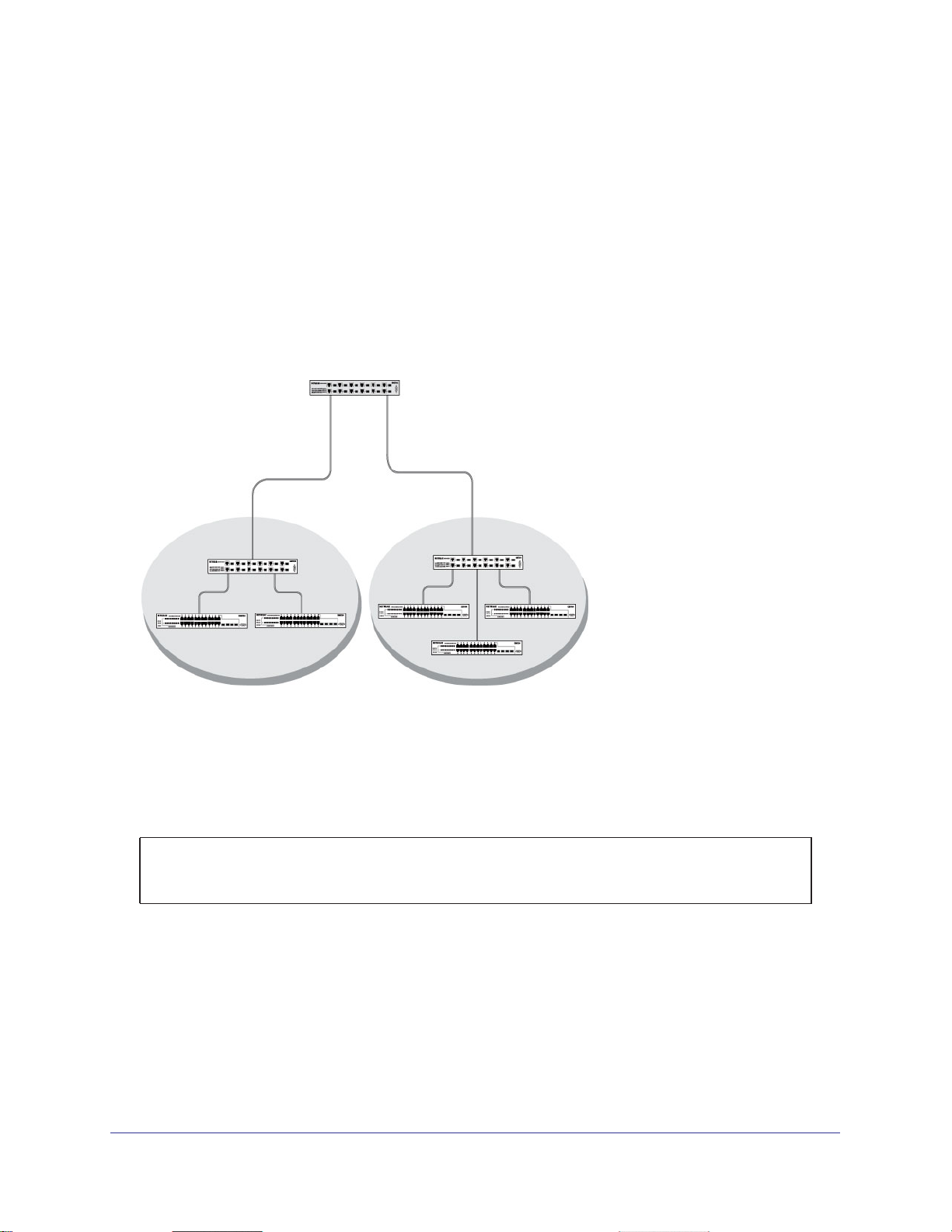
ProSafe M4100 and M7100 Managed Switches
Inter-area Router
The examples in this section show you how to configure a M4100 and M7100 Managed
Switch first as an inter-area router and then as a border router. They show two areas, each
with its own border router connected to one inter-area router.
The following figure shows a network segment with an inter-area router connecting areas
0.0.0.2 and 0.0.0.3.
M7100 Managed Switch as the inter-area router in the diagram by enabling OSPF on port
1/0/2 in area 0.0.0.2 and port 1/0/3 in area 0.0.0.3.
The sample script shows the commands used to configure a M4100 and
Layer 3 switch acting as
an inter-area router
Port 1/0/2
192.150.2.1
Border
Router
Area 2 Area 3
Figure 11. Network segment with an inter-area router connecting areas 0.0.0.2 and 0.0.0.3
Port 1/0/3
192.150.3.1
Border
Router
CLI: Configure an Inter-area Router
1. Enable routing for the switch.
(Netgear Switch) #config
(Netgear Switch) (Config)#ip routing
(Netgear Switch) (Config)#exit
Chapter 7. OSPF | 87
Page 88

ProSafe M4100 and M7100 Managed Switches
2. Assign IP addresses to ports.
(Netgear Switch) #config
(Netgear Switch) (Config)#interface 1/0/2
(Netgear Switch) (Interface 1/0/2)#routing
(Netgear Switch) (Interface 1/0/2)#ip address 192.150.2.1 255.255.255.0
(Netgear Switch) (Interface 1/0/2)#exit
(Netgear Switch) (Config)#interface 1/0/3
(Netgear Switch) (Interface 1/0/3)#routing
(Netgear Switch) (Interface 1/0/3)#ip address 192.150.3.1 255.255.255.0
(Netgear Switch) (Interface 1/0/3)#exit
(Netgear Switch) (Config)#exit
3. Specify the router ID, and enable OSPF for the switch. Set disable1583 compatibility to
prevent a routing loop.
(Netgear Switch) #config
(Netgear Switch) (Config)#router ospf
(Netgear Switch) (Config router)#enable
(Netgear Switch) (Config router)#router-id 192.150.9.9
(Netgear Switch) (Config router)#no 1583compatibility
(Netgear Switch) (Config router)#exit
(Netgear Switch) (Config)#exit
4. Enable OSPF, and set the OSPF priority and cost for the ports.
(Netgear Switch) #config
(Netgear Switch) (Config)#interface 1/0/2
(Netgear Switch) (Interface 1/0/2)#ip ospf
(Netgear Switch) (Interface 1/0/2)#ip ospf areaid 0.0.0.2
(Netgear Switch) (Interface 1/0/2)#ip ospf priority 128
(Netgear Switch) (Interface 1/0/2)#ip ospf cost 32
(Netgear Switch) (Interface 1/0/2)#exit
(Netgear Switch) (Config)#interface 1/0/3
(Netgear Switch) (Interface 1/0/3)#ip ospf
(Netgear Switch) (Interface 1/0/3)#ip ospf areaid 0.0.0.3
(Netgear Switch) (Interface 1/0/3)#ip ospf priority 255
(Netgear Switch) (Interface 1/0/3)#ip ospf cost 64
(Netgear Switch) (Interface 1/0/3)#exit
(Netgear Switch) (Config)#exit
88 | Chapter 7. OSPF
Page 89
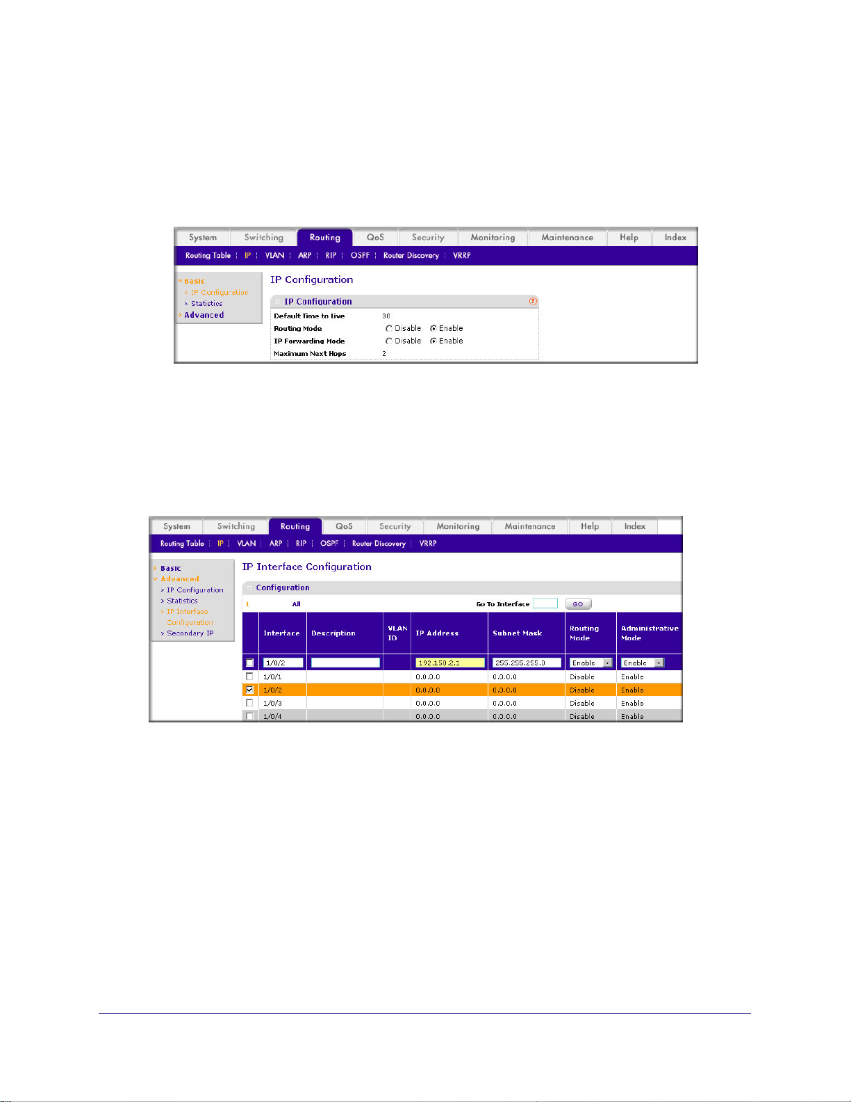
ProSafe M4100 and M7100 Managed Switches
Web Interface: Configure an Inter-area Router
1. Enable IP routing on the switch.
a. Select Routing > IP > Basic > IP Configuration.
A screen similar to the following displays.
b. For Routing Mode, select the Enable radio button.
c. Click Apply to save the settings.
2. Assign IP address 192.150.2.1 to port 1/0/2.
a. Select Routing > IP >
Advanced > IP Interface Configuration.
A screen similar to the following displays.
b. Scroll down and select the interface 1/0/2 check box.
Now 1/0/2 appears in the Interface field at the top.
c. Enter the following information:
• In the IP Address field, enter 192.150.2.1.
• In the Subnet Mask field, enter 255.255.255.0.
• In the Administrative Mode field, select Enable.
d. Click Apply to save the settings.
3. Assign IP address 192.150.3.1 to port 1/0/3:
a. Select Routing > IP >
Advanced > IP Interface Configuration.
Chapter 7. OSPF | 89
Page 90

ProSafe M4100 and M7100 Managed Switches
A screen similar to the following displays.
b. Scroll down and select the interface 1/0/3 check box.
Now 1/0/3 appears in the Interface field at the top.
c. Enter the following information:
• In the IP Address field, enter 192.150.3.1.
• In the Network Mask field, enter 255.255.255.0.
• In the Administrative Mode field, select Enable.
d. Click Apply to save the settings.
4. Specify the router ID, and enable OSPF for the switch.
a. Select Routing > OSPF >
Advanced > OSPF Configuration.
A screen similar to the following displays.
b. Under OSPF Configuration, enter the following information:
• In the Router ID field, enter 192.150.9.9.
• In the OSPF Admin Mode field, select Enable.
90 | Chapter 7. OSPF
Page 91
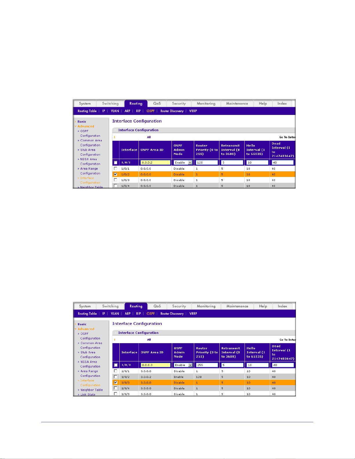
ProSafe M4100 and M7100 Managed Switches
• In the RFC 1583 Compatibility field, select Disable.
c. Click Apply to save the settings.
5. Enable OSPF on port 1/0/2.
a. Select Routing > OSPF >
Advanced > Interface Configuration.
A screen similar to the following displays.
b. Scroll downand select the interface 1/0/2 check box.
Now 1/0/2 appears in the Interface field at the top.
• In the OSPF Area
• In the OSPF Admin
ID field, enter 0.0.0.2.
Mode field, select Enable.
• In the Priority field, enter 128.
• In the Metric Cost field, enter 32.
c. Click Apply to save the settings.
6. Enable OSPF on port 1/0/3.
a. Select Routing > OSPF >
Advanced > Interface Configuration.
A screen similar to the following displays.
b. Scroll down and select the interface 1/0/3 check box.
Chapter 7. OSPF | 91
Page 92

ProSafe M4100 and M7100 Managed Switches
Now 1/0/3 appears in the Interface field at the top.
• In the OSPF Area
• In the OSPF Admin
ID field, enter 0.0.0.3.
Mode field, select Enable.
• In the Priority field, enter 255.
• In the Metric Cost field, enter 64.
c. Click Apply to save the settings.
OSPF on a Border Router
The example is shown as CLI commands and as a Web interface procedure. For an OSPF
sample network, see Figure 11 on page 87.
CLI: Configure OSPF on a Border Router
1. Enable routing for the switch.
(Netgear Switch) #config
(Netgear Switch) (Config)#ip routing
2. Enable routing and assign IPs for ports 1/0/2, 1/0/3, and 1/0/4.
(Netgear Switch) (Config)#interface 1/0/2
(Netgear Switch) (Interface 1/0/2)#routing
(Netgear Switch) (Interface 1/0/2)#ip address 192.150.2.2 255.255.255.0
(Netgear Switch) (Interface 1/0/2)#exit
(Netgear Switch) (Config)#interface 1/0/3
(Netgear Switch) (Interface 1/0/3)#routing
(Netgear Switch) (Interface 1/0/3)#ip address 192.130.3.1 255.255.255.0
(Netgear Switch) (Interface 1/0/3)#exit
(Netgear Switch) (Config)#interface 1/0/4
(Netgear Switch) (Interface 1/0/4)#routing
(Netgear Switch) (Interface 1/0/4)#ip address 192.64.4.1 255.255.255.0
(Netgear Switch) (Interface 1/0/4)#exit
3. Specify the router ID, and enable OSPF for the switch.
92 | Chapter 7. OSPF
Page 93

ProSafe M4100 and M7100 Managed Switches
Set disable 1583compatibility to prevent a routing loop.
(Netgear Switch) (Config)#router ospf
(Netgear Switch) (Config router)#enable
(Netgear Switch) (Config router)#router-id 192.130.1.1
(Netgear Switch) (Config router)#no 1583compatibility
(Netgear Switch) (Config router)#exit
(Netgear Switch) (Config)#exit
4. Enable OSPF for the ports, and set the OSPF priority and cost for the ports.
(Netgear Switch) #config
(Netgear Switch) (Config)#interface 1/0/2
(Netgear Switch) (Interface 1/0/2)#ip ospf
(Netgear Switch) (Interface 1/0/2)#ip ospf areaid 0.0.0.2
(Netgear Switch) (Interface 1/0/2)#ip ospf priority 128
(Netgear Switch) (Interface 1/0/2)#ip ospf cost 32
(Netgear Switch) (Interface 1/0/2)#exit
(Netgear Switch) (Config)#interface 1/0/3
(Netgear Switch) (Interface 1/0/3)#ip ospf
(Netgear Switch) (Interface 1/0/3)#ip ospf areaid 0.0.0.2
(Netgear Switch) (Interface 1/0/3)#ip ospf priority 255
(Netgear Switch) (Interface 1/0/3)#ip ospf cost 64
(Netgear Switch) (Interface 1/0/3)#exit
(Netgear Switch) (Config)#interface 1/0/4
(Netgear Switch) (Interface 1/0/4)#ip ospf
(Netgear Switch) (Interface 1/0/4)#ip ospf areaid 0.0.0.2
(Netgear Switch) (Interface 1/0/4)#ip ospf priority 255
(Netgear Switch) (Interface 1/0/4)#ip ospf cost 64
(Netgear Switch) (Interface 1/0/4)#exit
(Netgear Switch) (Config)#exit
Web Interface: Configure OSPF on a Border Router
1. Enable IP routing on the switch.
a. Select Routing > IP > Basic > IP Configuration.
Chapter 7. OSPF | 93
Page 94

A screen similar to the following displays.
b. For Routing Mode, select the Enable radio button.
c. Click Apply to save the settings.
2. Assign IP address 192.150.2.2 to port 1/0/2.
a. Select Routing > IP >
Advanced > IP Interface Configuration.
A screen similar to the following displays.
ProSafe M4100 and M7100 Managed Switches
b. Scroll down and select the interface 1/0/2 check box.
Now 1/0/2 appears in the Interface field at the top.
c. Enter the following information:
• In the IP Address field, enter 192.150.2.2.
• In the Network Mask field, enter 255.255.255.0.
• In the Admin Mode field, select Enable.
d. Click Apply to save the settings.
3. Assign IP address 192.130.3.1 to port 1/0/3:
a. Select Routing > IP >
94 | Chapter 7. OSPF
Advanced > IP Interface Configuration.
Page 95

ProSafe M4100 and M7100 Managed Switches
A screen similar to the following displays.
b. Scroll down and select the interface 1/0/3 check box.
Now 1/0/3 appears in the Interface field at the top.
c. Enter the following information:
• In the IP Address field, enter 192.130.3.1.
• In the Network Mask field, enter 255.255.255.0.
• In the Admin Mode field, select Enable.
d. Click Apply to save the settings.
4. Assign IP address 192.64.4.1 to port 1/0/4.
a. Select Routing > IP >
Advanced > IP Interface Configuration.
A screen similar to the following displays.
b. Scroll down and select the interface 1/0/4 check box. Now 1/0/4 appears in the
Interface field at the top.
c. Enter the following information:
• In the IP Address field, enter 192.64.4.1.
• In the Network Mask field, enter 255.255.255.0.
• In the Admin Mode field, select Enable.
Chapter 7. OSPF | 95
Page 96
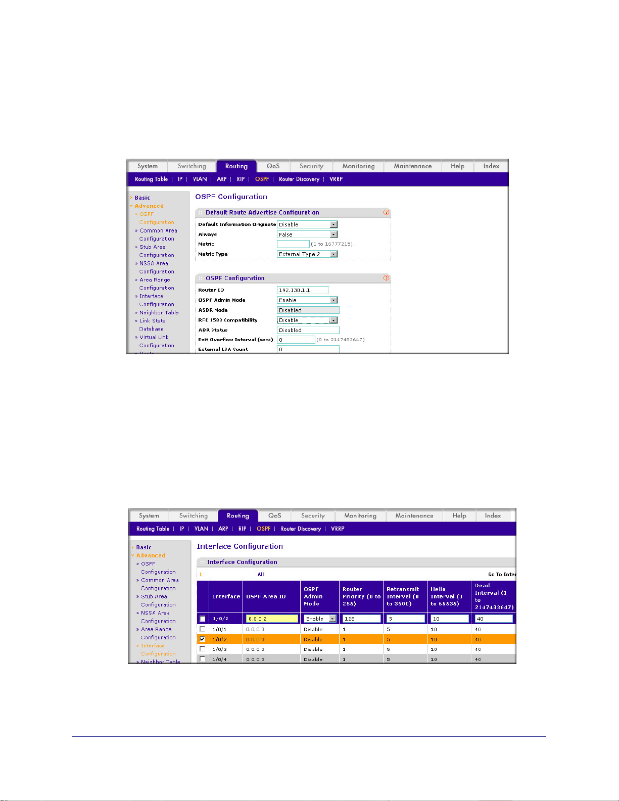
ProSafe M4100 and M7100 Managed Switches
d. Click Apply to save the settings.
5. Specify the router ID, and enable OSPF for the switch.
a. Select Routing > OSPF >
Advanced > OSPF Configuration.
A screen similar to the following displays.
b. Under OSPF Configuration, enter the following information:
• In the Router ID field, enter 192.130.1.1.
• In the OSPF Admin Mode field, select Enable .
• In the RFC 1583 Compatibility field, select Disable.
c. Click Apply to save the settings.
6. Enable OSPF on the port 1/0/2.
a. Select Routing > OSPF >
Advanced > Interface Configuration.
A screen similar to the following displays.
b. Under Interface Configuration, scroll down and select the interface 1/0/2 check box.
Now 1/0/2 appears in the Interface field at the top.
96 | Chapter 7. OSPF
Page 97

ProSafe M4100 and M7100 Managed Switches
• In the OSPF Area ID field, enter 0.0.0.2.
• In the OSPF Admin
Mode field, select Enable.
• In the Router Priority (0 to 255) field, enter 128.
• In the Metric Cost field, enter 32.
c. Click Apply to save the settings.
7. Enable OSPF on port 1/0/3.
a. Select Routing > OSPF >
Advanced > Interface Configuration.
A screen similar to the following displays.
b. Under Interface Configuration, scroll down and select the interface 1/0/3 check box.
Now 1/0/3 appears in the Interface field at the top.
• In the OSPF Area
• In the OSPF Admin
ID field, enter 0.0.0.3.
Mode field, select Enable.
• In the Priority field, enter 255.
• In the Metric Cost field, enter 64.
c. Click Apply to save the settings.
8. Enable OSPF on port 1/0/4.
a. Select Routing > OSPF >
Advanced > Interface Configuration.
Chapter 7. OSPF | 97
Page 98
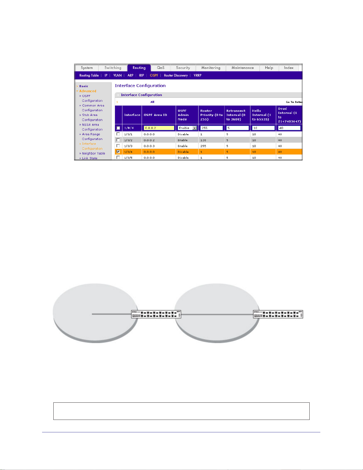
ProSafe M4100 and M7100 Managed Switches
A screen similar to the following displays.
b. Under Interface Configuration, scroll down and select the interface 1/0/4 check box.
Now 1/0/4 appears in the Interface field at the top.
• In the OSPF Area
• In the OSPF Admin
ID field, enter 0.0.0.2.
Mode field, select the Enable.
• In the Priority field, enter 255.
• In the Metric Cost field, enter 64.
c. Click Apply to save the settings.
Stub Areas
The example is shown as CLI commands and as a Web interface procedure.
Layer 3
Port 2/0/11
Area 0 Area 1
Figure 12. Area 1 is a stub area
switch
Port 2/0/191
Port 1/0/151
Layer 3
switch
CLI: Configure Area 1 as a Stub Area on A1
1. Enable routing on the switch.
(Netgear Switch) #config
(Netgear Switch) (Config)#ip routing
98 | Chapter 7. OSPF
Page 99

ProSafe M4100 and M7100 Managed Switches
2. Set the router IDd to 1.1.1.1.
(Netgear Switch) (Config)#router ospf
(Netgear Switch) (Config-router)#router-id 1.1.1.1
3. Configure area 0.0.0.1 as a stub area
(Netgear Switch) (Config-router)#area 0.0.0.1 stub
.
4. Switch A injects a default route only to area 0.0.0.1.
(Netgear Switch) (Config-router)#no area 0.0.0.1 stub summarylsa
(Netgear Switch) (Config-router)#exit
5. Enable OSPF area 0 on ports 2/0/11.
(Netgear Switch) (Config)#interface 2/0/11
(Netgear Switch) (Interface 2/0/11)#routing
(Netgear Switch) (Interface 2/0/11)#ip address 192.168.10.1 255.255.255.0
(Netgear Switch) (Interface 2/0/11)#ip ospf
(Netgear Switch) (Interface 2/0/11)#exit
6. Enable OSPF area 0.0.0.1 on 2/0/19.
(Netgear Switch) (Config)#interface 2/0/19
(Netgear Switch) (Interface 2/0/19)#routing
(Netgear Switch) (Interface 2/0/19)#ip address 192.168.20.1 255.255.255.0
(Netgear Switch) (Interface 2/0/19)#ip ospf
(Netgear Switch) (Interface 2/0/19)#ip ospf areaid 0.0.0.1
(Netgear Switch) (Interface 2/0/19)#exit
Chapter 7. OSPF | 99
Page 100
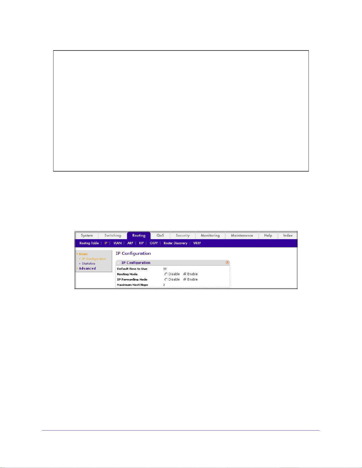
ProSafe M4100 and M7100 Managed Switches
(Netgear Switch) (Config)#ex
(Netgear Switch) #show ip ospf neighbor interface all
Router ID IP Address Neighbor Interface State
---------------- ----------- ------------------- ---------
4.4.4.4 192.168.10.2 2/0/11 Full
2.2.2.2 192.168.20.2 2/0/19 Full
(Netgear Switch) #show ip route
Total Number of Routes......................... 4
Network Subnet Next Hop Next Hop
Address Mask Protocol Intf IP Address
--------------- --------------- ------------ --------- ---------------
14.1.1.0 255.255.255.0 OSPF Inter 2/0/11 192.168.10.2
14.1.2.0 255.255.255.0 OSPF Inter 2/0/11 192.168.10.2 192.168.10.0
255.255.255.0 Local 2/0/11 192.168.10.1
192.168.20.0 255.255.255.0 Local 2/0/19 192.168.20.1
Web Interface: Configure Area 1 as a Stub Area on A1
1. Enable IP routing on the switch.
a. Select Routing > IP > Basic > IP Configuration.
A screen similar to the following displays.
b. For Routing Mode, select the Enable radio button.
c. Click Apply to save the settings.
2. Assign IP address 192.168.10.1 to port 2/0/1
a. Select Routing > IP >
Advanced > IP Interface Configuration.
1.
100 | Chapter 7. OSPF
 Loading...