

Page 1

M5300, M6100, and M7100 Series ProSAFE Managed Switches
CLI Command Reference Manual
Software Version 11.0.0
April 2015
202-11526-02
350 East Plumeria Drive
San Jose, CA 95134
USA
Page 2

M5300, M6100, and M7100 Series ProSAFE Managed Switches
Support
Thank you for selecting NETGEAR products.
After installing your device, locate the serial number on the label of your product and use it to register your product at
https://my.netgear.com. You must register your product before you can use NETGEAR telephone support. NETGEAR
recommends registering your product through the NETGEAR website. For product updates and web support, visit
http://support.netgear.com.
Phone (US & Canada only): 1-888-NETGEAR.
Phone (Other Countries): Check the list of phone numbers at http://support.netgear.com/general/contact/default.aspx.
Contact your Internet service provider for technical support.
Compliance
For regulatory compliance information, visit http://www.netgear.com/about/regulatory.
See the regulatory compliance document before connecting the power supply.
Trademarks
© NETGEAR, Inc. NETGEAR and the NETGEAR Logo are trademarks of NETGEAR, Inc. Any non-NETGEAR trademarks are
used for reference purposes only.
Revision History
Publication
Part Number
202-11526-01 March 2015 Added the following chapter and section:
Publish Date Comments
• Chapter 5, Stacking Commands
• Switch Port Commands
Added the following main commands:
• ip management
• snmp-server port and show snmp-server
• show fiber-ports optics-diag
• exception dump ftp-server, exception dump compression, exception dump
stack-ip-address protocol, exception dump stack-ip-address add, and
exception dump stack-ip-address remove
• exception nmi
• show msg-queue
• sw reset and show sw reset
• peer detection interval
• system-mac
• system-priority
• debug vpc peer-link data-message
• set igmp header-validation
• show igmpsnooping querier
• set mld proxy-querier and show mldsnooping proxy-querier
Made changes and corrections to other commands.
202-11457-02 September 2014 Corrected the syntax of the {deny | permit} (IPv6) command.
Added a note to all debug commands.
202-11457-01 August 2014 Initial publication of this manual.
2
Page 3

Contents
Chapter 1 About the NETGEAR Managed Switch Software
Chapter 2 Using the Command-Line Interface
Chapter 3 NETGEAR Managed Switch Software Modules
Scope. . . . . . . . . . . . . . . . . . . . . . . . . . . . . . . . . . . . . . . . . . . . . . . . . . . . . . . . . . . . . . . 9
Product Concept . . . . . . . . . . . . . . . . . . . . . . . . . . . . . . . . . . . . . . . . . . . . . . . . . . . . . 9
Command Syntax . . . . . . . . . . . . . . . . . . . . . . . . . . . . . . . . . . . . . . . . . . . . . . . . . . . 11
Command Conventions . . . . . . . . . . . . . . . . . . . . . . . . . . . . . . . . . . . . . . . . . . . . . . 11
Common Parameter Values . . . . . . . . . . . . . . . . . . . . . . . . . . . . . . . . . . . . . . . . . . . 12
unit/slot/port Naming Convention. . . . . . . . . . . . . . . . . . . . . . . . . . . . . . . . . . . . . 13
Using the No Form of a Command . . . . . . . . . . . . . . . . . . . . . . . . . . . . . . . . . . . . . 14
Executing Show Commands. . . . . . . . . . . . . . . . . . . . . . . . . . . . . . . . . . . . . . . . . . . 14
CLI Output Filtering. . . . . . . . . . . . . . . . . . . . . . . . . . . . . . . . . . . . . . . . . . . . . . . . . . 14
Command Modes . . . . . . . . . . . . . . . . . . . . . . . . . . . . . . . . . . . . . . . . . . . . . . . . . . . 17
Command Completion and Abbreviation. . . . . . . . . . . . . . . . . . . . . . . . . . . . . . . . 22
CLI Error Messages . . . . . . . . . . . . . . . . . . . . . . . . . . . . . . . . . . . . . . . . . . . . . . . . . . 22
CLI Line-Editing Conventions . . . . . . . . . . . . . . . . . . . . . . . . . . . . . . . . . . . . . . . . . 23
Using CLI Help . . . . . . . . . . . . . . . . . . . . . . . . . . . . . . . . . . . . . . . . . . . . . . . . . . . . . . 24
Accessing the CLI. . . . . . . . . . . . . . . . . . . . . . . . . . . . . . . . . . . . . . . . . . . . . . . . . . . . 25
Chapter 4 Chassis Commands
General Chassis Commands . . . . . . . . . . . . . . . . . . . . . . . . . . . . . . . . . . . . . . . . . . . 27
Backplane Port Commands . . . . . . . . . . . . . . . . . . . . . . . . . . . . . . . . . . . . . . . . . . . 36
Chassis Firmware Synchronization Commands. . . . . . . . . . . . . . . . . . . . . . . . . . . 37
Nonstop Forwarding Commands for Chassis Configuration . . . . . . . . . . . . . . . . 39
Chapter 5 Stacking Commands
Dedicated Port Stacking Commands . . . . . . . . . . . . . . . . . . . . . . . . . . . . . . . . . . . 44
Stack Port Commands . . . . . . . . . . . . . . . . . . . . . . . . . . . . . . . . . . . . . . . . . . . . . . . 55
Stack Firmware Synchronization Commands . . . . . . . . . . . . . . . . . . . . . . . . . . . . 61
Nonstop Forwarding Commands for Stack Configuration. . . . . . . . . . . . . . . . . . 63
Chapter 6 Management Commands
Configure the Switch Management CPU . . . . . . . . . . . . . . . . . . . . . . . . . . . . . . . . 69
CPU Queue Commands. . . . . . . . . . . . . . . . . . . . . . . . . . . . . . . . . . . . . . . . . . . . . . . 71
3
Page 4

M5300, M6100, and M7100 Series ProSAFE Managed Switches
Network Interface Commands . . . . . . . . . . . . . . . . . . . . . . . . . . . . . . . . . . . . . . . . 72
Console Port Access Commands . . . . . . . . . . . . . . . . . . . . . . . . . . . . . . . . . . . . . . . 78
Telnet Commands . . . . . . . . . . . . . . . . . . . . . . . . . . . . . . . . . . . . . . . . . . . . . . . . . . . 81
Secure Shell Commands . . . . . . . . . . . . . . . . . . . . . . . . . . . . . . . . . . . . . . . . . . . . . . 86
Management Security Commands . . . . . . . . . . . . . . . . . . . . . . . . . . . . . . . . . . . . . 88
Management Access Control List Commands. . . . . . . . . . . . . . . . . . . . . . . . . . . . 89
Hypertext Transfer Protocol Commands . . . . . . . . . . . . . . . . . . . . . . . . . . . . . . . . 94
Access Commands. . . . . . . . . . . . . . . . . . . . . . . . . . . . . . . . . . . . . . . . . . . . . . . . . . 101
User Account Commands. . . . . . . . . . . . . . . . . . . . . . . . . . . . . . . . . . . . . . . . . . . . 103
Per-Command Authorization . . . . . . . . . . . . . . . . . . . . . . . . . . . . . . . . . . . . . . 107
Exec Authorization . . . . . . . . . . . . . . . . . . . . . . . . . . . . . . . . . . . . . . . . . . . . . . . 107
SNMP Commands . . . . . . . . . . . . . . . . . . . . . . . . . . . . . . . . . . . . . . . . . . . . . . . . . . 133
RADIUS Commands . . . . . . . . . . . . . . . . . . . . . . . . . . . . . . . . . . . . . . . . . . . . . . . . . 145
TACACS+ Commands . . . . . . . . . . . . . . . . . . . . . . . . . . . . . . . . . . . . . . . . . . . . . . . 160
Configuration Scripting Commands . . . . . . . . . . . . . . . . . . . . . . . . . . . . . . . . . . . 165
Prelogin Banner, System Prompt, and Host Name Commands. . . . . . . . . . . . . 167
Chapter 7 Utility Commands
AutoInstall Commands . . . . . . . . . . . . . . . . . . . . . . . . . . . . . . . . . . . . . . . . . . . . . . 171
CLI Output Filtering Commands . . . . . . . . . . . . . . . . . . . . . . . . . . . . . . . . . . . . . . 175
Dual Image Commands. . . . . . . . . . . . . . . . . . . . . . . . . . . . . . . . . . . . . . . . . . . . . . 177
System Information and Statistics Commands . . . . . . . . . . . . . . . . . . . . . . . . . . 178
Switch Services Commands. . . . . . . . . . . . . . . . . . . . . . . . . . . . . . . . . . . . . . . . . . 207
Logging Commands. . . . . . . . . . . . . . . . . . . . . . . . . . . . . . . . . . . . . . . . . . . . . . . . . 209
Email Alerting and Mail Server Commands . . . . . . . . . . . . . . . . . . . . . . . . . . . . . 217
System Utility and Clear Commands . . . . . . . . . . . . . . . . . . . . . . . . . . . . . . . . . . 223
Simple Network Time Protocol Commands . . . . . . . . . . . . . . . . . . . . . . . . . . . . . 235
Time Zone Commands . . . . . . . . . . . . . . . . . . . . . . . . . . . . . . . . . . . . . . . . . . . . . . 241
DHCP Server Commands . . . . . . . . . . . . . . . . . . . . . . . . . . . . . . . . . . . . . . . . . . . . 245
DNS Client Commands . . . . . . . . . . . . . . . . . . . . . . . . . . . . . . . . . . . . . . . . . . . . . . 258
IP Address Conflict Commands . . . . . . . . . . . . . . . . . . . . . . . . . . . . . . . . . . . . . . . 263
Serviceability Packet Tracing Commands . . . . . . . . . . . . . . . . . . . . . . . . . . . . . . 264
Support Mode Commands . . . . . . . . . . . . . . . . . . . . . . . . . . . . . . . . . . . . . . . . . . . 302
Cable Test Command . . . . . . . . . . . . . . . . . . . . . . . . . . . . . . . . . . . . . . . . . . . . . . . 305
Power Management Commands . . . . . . . . . . . . . . . . . . . . . . . . . . . . . . . . . . . . . . 306
USB commands . . . . . . . . . . . . . . . . . . . . . . . . . . . . . . . . . . . . . . . . . . . . . . . . . . . . 310
sFlow Commands. . . . . . . . . . . . . . . . . . . . . . . . . . . . . . . . . . . . . . . . . . . . . . . . . . . 311
Switch Database Management Template Commands . . . . . . . . . . . . . . . . . . . . 318
Green Ethernet Commands . . . . . . . . . . . . . . . . . . . . . . . . . . . . . . . . . . . . . . . . . . 322
Remote Monitoring Commands . . . . . . . . . . . . . . . . . . . . . . . . . . . . . . . . . . . . . . 331
Statistics Application Commands . . . . . . . . . . . . . . . . . . . . . . . . . . . . . . . . . . . . . 347
Chapter 8 Switching Commands
Port Configuration Commands . . . . . . . . . . . . . . . . . . . . . . . . . . . . . . . . . . . . . . . 357
Spanning Tree Protocol Commands . . . . . . . . . . . . . . . . . . . . . . . . . . . . . . . . . . . 364
VLAN Commands. . . . . . . . . . . . . . . . . . . . . . . . . . . . . . . . . . . . . . . . . . . . . . . . . . . 395
4
Page 5

M5300, M6100, and M7100 Series ProSAFE Managed Switches
Switch Port Commands . . . . . . . . . . . . . . . . . . . . . . . . . . . . . . . . . . . . . . . . . . . . . 408
Double VLAN Commands . . . . . . . . . . . . . . . . . . . . . . . . . . . . . . . . . . . . . . . . . . . . 413
Private VLAN Commands . . . . . . . . . . . . . . . . . . . . . . . . . . . . . . . . . . . . . . . . . . . .416
Voice VLAN Commands . . . . . . . . . . . . . . . . . . . . . . . . . . . . . . . . . . . . . . . . . . . . . 418
Provisioning (IEEE 802.1p) Commands. . . . . . . . . . . . . . . . . . . . . . . . . . . . . . . . 422
Asymmetric Flow Control. . . . . . . . . . . . . . . . . . . . . . . . . . . . . . . . . . . . . . . . . . . . 422
Protected Ports Commands. . . . . . . . . . . . . . . . . . . . . . . . . . . . . . . . . . . . . . . . . . 424
Private Group Commands . . . . . . . . . . . . . . . . . . . . . . . . . . . . . . . . . . . . . . . . . . . 426
GARP Commands. . . . . . . . . . . . . . . . . . . . . . . . . . . . . . . . . . . . . . . . . . . . . . . . . . . 428
GVRP Commands. . . . . . . . . . . . . . . . . . . . . . . . . . . . . . . . . . . . . . . . . . . . . . . . . . . 430
GMRP Commands . . . . . . . . . . . . . . . . . . . . . . . . . . . . . . . . . . . . . . . . . . . . . . . . . . 432
Port-Based Network Access Control Commands. . . . . . . . . . . . . . . . . . . . . . . . 434
802.1X Supplicant Commands . . . . . . . . . . . . . . . . . . . . . . . . . . . . . . . . . . . . . . . 456
Storm-Control Commands. . . . . . . . . . . . . . . . . . . . . . . . . . . . . . . . . . . . . . . . . . . 460
Link Local Protocol Filtering Commands . . . . . . . . . . . . . . . . . . . . . . . . . . . . . . . 467
MRP Commands . . . . . . . . . . . . . . . . . . . . . . . . . . . . . . . . . . . . . . . . . . . . . . . . . . . 468
MMRP Commands. . . . . . . . . . . . . . . . . . . . . . . . . . . . . . . . . . . . . . . . . . . . . . . . . . 469
MVRP Commands . . . . . . . . . . . . . . . . . . . . . . . . . . . . . . . . . . . . . . . . . . . . . . . . . . 473
Port-Channel/LAG (802.3ad) Commands . . . . . . . . . . . . . . . . . . . . . . . . . . . . . 476
VPC Commands . . . . . . . . . . . . . . . . . . . . . . . . . . . . . . . . . . . . . . . . . . . . . . . . . . . .495
Port Mirroring Commands . . . . . . . . . . . . . . . . . . . . . . . . . . . . . . . . . . . . . . . . . . . 509
Static MAC Filtering Commands . . . . . . . . . . . . . . . . . . . . . . . . . . . . . . . . . . . . . . 512
DHCP L2 Relay Agent Commands. . . . . . . . . . . . . . . . . . . . . . . . . . . . . . . . . . . . . 516
DHCP Client Commands. . . . . . . . . . . . . . . . . . . . . . . . . . . . . . . . . . . . . . . . . . . . . 523
DHCP Snooping Configuration Commands . . . . . . . . . . . . . . . . . . . . . . . . . . . . . 525
Dynamic ARP Inspection Commands . . . . . . . . . . . . . . . . . . . . . . . . . . . . . . . . . . 535
MVR Commands . . . . . . . . . . . . . . . . . . . . . . . . . . . . . . . . . . . . . . . . . . . . . . . . . . .542
IGMP Snooping Configuration Commands . . . . . . . . . . . . . . . . . . . . . . . . . . . . . 549
IGMP Snooping Querier Commands. . . . . . . . . . . . . . . . . . . . . . . . . . . . . . . . . . . 558
MLD Snooping Commands. . . . . . . . . . . . . . . . . . . . . . . . . . . . . . . . . . . . . . . . . . . 563
MLD Snooping Querier Commands . . . . . . . . . . . . . . . . . . . . . . . . . . . . . . . . . . .571
Port Security Commands . . . . . . . . . . . . . . . . . . . . . . . . . . . . . . . . . . . . . . . . . . . . 576
LLDP (802.1AB) Commands . . . . . . . . . . . . . . . . . . . . . . . . . . . . . . . . . . . . . . . . . 581
LLDP-MED Commands. . . . . . . . . . . . . . . . . . . . . . . . . . . . . . . . . . . . . . . . . . . . . . 589
Denial of Service Commands. . . . . . . . . . . . . . . . . . . . . . . . . . . . . . . . . . . . . . . . . 597
MAC Database Commands. . . . . . . . . . . . . . . . . . . . . . . . . . . . . . . . . . . . . . . . . . . 607
ISDP Commands . . . . . . . . . . . . . . . . . . . . . . . . . . . . . . . . . . . . . . . . . . . . . . . . . . . 609
UniDirectional Link Detection Commands. . . . . . . . . . . . . . . . . . . . . . . . . . . . . . 617
Link Debounce Commands. . . . . . . . . . . . . . . . . . . . . . . . . . . . . . . . . . . . . . . . . . . 620
Chapter 9 Data Center Commands
Data Center Bridging Exchange Protocol Commands . . . . . . . . . . . . . . . . . . . . 624
Enhanced Transmission Selection and Traffic Class Group . . . . . . . . . . . . . . . .631
FIP Snooping Commands . . . . . . . . . . . . . . . . . . . . . . . . . . . . . . . . . . . . . . . . . . . . 636
Priority-Based Flow Control Commands . . . . . . . . . . . . . . . . . . . . . . . . . . . . . . . 655
5
Page 6

M5300, M6100, and M7100 Series ProSAFE Managed Switches
Chapter 10 Routing Commands
Address Resolution Protocol Commands . . . . . . . . . . . . . . . . . . . . . . . . . . . . . . . 661
IP Routing Commands. . . . . . . . . . . . . . . . . . . . . . . . . . . . . . . . . . . . . . . . . . . . . . . 667
Routing Policy Commands . . . . . . . . . . . . . . . . . . . . . . . . . . . . . . . . . . . . . . . . . . . 691
Router Discovery Protocol Commands . . . . . . . . . . . . . . . . . . . . . . . . . . . . . . . . 715
Virtual LAN Routing Commands . . . . . . . . . . . . . . . . . . . . . . . . . . . . . . . . . . . . . . 719
Virtual Router Redundancy Protocol Commands . . . . . . . . . . . . . . . . . . . . . . . . 722
DHCP and BootP Relay Commands. . . . . . . . . . . . . . . . . . . . . . . . . . . . . . . . . . . . 731
IP Helper Commands. . . . . . . . . . . . . . . . . . . . . . . . . . . . . . . . . . . . . . . . . . . . . . . . 733
Open Shortest Path First Commands . . . . . . . . . . . . . . . . . . . . . . . . . . . . . . . . . . 741
General OSPF Commands . . . . . . . . . . . . . . . . . . . . . . . . . . . . . . . . . . . . . . . . . 741
OSPF Interface Commands . . . . . . . . . . . . . . . . . . . . . . . . . . . . . . . . . . . . . . . . 762
IP Event Dampening Commands. . . . . . . . . . . . . . . . . . . . . . . . . . . . . . . . . . . . 768
OSPF Graceful Restart Commands . . . . . . . . . . . . . . . . . . . . . . . . . . . . . . . . . . . . 770
OSPFv2 Stub Router Commands . . . . . . . . . . . . . . . . . . . . . . . . . . . . . . . . . . . 773
OSPF Show Commands . . . . . . . . . . . . . . . . . . . . . . . . . . . . . . . . . . . . . . . . . . . 775
Routing Information Protocol Commands . . . . . . . . . . . . . . . . . . . . . . . . . . . . . . 796
ICMP Throttling Commands. . . . . . . . . . . . . . . . . . . . . . . . . . . . . . . . . . . . . . . . . . 804
Chapter 11 Captive Portal Commands
Captive Portal Global Commands . . . . . . . . . . . . . . . . . . . . . . . . . . . . . . . . . . . . . 808
Captive Portal Configuration Commands . . . . . . . . . . . . . . . . . . . . . . . . . . . . . . 813
Captive Portal Status Commands . . . . . . . . . . . . . . . . . . . . . . . . . . . . . . . . . . . . . 822
Captive Portal Client Connection Commands. . . . . . . . . . . . . . . . . . . . . . . . . . . 824
Captive Portal Interface Commands. . . . . . . . . . . . . . . . . . . . . . . . . . . . . . . . . . . 827
Captive Portal Local User Commands . . . . . . . . . . . . . . . . . . . . . . . . . . . . . . . . . 829
Captive Portal User Group Commands. . . . . . . . . . . . . . . . . . . . . . . . . . . . . . . . . 836
Chapter 12 Border Gateway Protocol Commands
BGP Commands . . . . . . . . . . . . . . . . . . . . . . . . . . . . . . . . . . . . . . . . . . . . . . . . . . . . 839
Routing Policy Commands . . . . . . . . . . . . . . . . . . . . . . . . . . . . . . . . . . . . . . . . . . . 916
Chapter 13 IPv6 Commands
IPv6 Management Commands . . . . . . . . . . . . . . . . . . . . . . . . . . . . . . . . . . . . . . . 923
Tunnel Interface Commands . . . . . . . . . . . . . . . . . . . . . . . . . . . . . . . . . . . . . . . . . 929
Loopback Interface Commands. . . . . . . . . . . . . . . . . . . . . . . . . . . . . . . . . . . . . . . 931
IPv6 Routing Commands . . . . . . . . . . . . . . . . . . . . . . . . . . . . . . . . . . . . . . . . . . . . 932
OSPFv3 Commands . . . . . . . . . . . . . . . . . . . . . . . . . . . . . . . . . . . . . . . . . . . . . . . . 967
Global OSPFv3 Commands . . . . . . . . . . . . . . . . . . . . . . . . . . . . . . . . . . . . . . . . 967
OSPFv3 Interface Commands. . . . . . . . . . . . . . . . . . . . . . . . . . . . . . . . . . . . . . 983
OSPFv3 Graceful Restart Commands . . . . . . . . . . . . . . . . . . . . . . . . . . . . . . . 988
OSPFv3 Stub Router Commands . . . . . . . . . . . . . . . . . . . . . . . . . . . . . . . . . . . 992
OSPFv3 Show Commands . . . . . . . . . . . . . . . . . . . . . . . . . . . . . . . . . . . . . . . . . 993
DHCPv6 Commands . . . . . . . . . . . . . . . . . . . . . . . . . . . . . . . . . . . . . . . . . . . . . . .1010
DHCPv6 Snooping Configuration Commands. . . . . . . . . . . . . . . . . . . . . . . . . .1023
6
Page 7

M5300, M6100, and M7100 Series ProSAFE Managed Switches
Chapter 14 Quality of Service Commands
Class of Service Commands. . . . . . . . . . . . . . . . . . . . . . . . . . . . . . . . . . . . . . . . .1035
Differentiated Services Commands . . . . . . . . . . . . . . . . . . . . . . . . . . . . . . . . . .1043
DiffServ Class Commands . . . . . . . . . . . . . . . . . . . . . . . . . . . . . . . . . . . . . . . . . .1044
DiffServ Policy Commands . . . . . . . . . . . . . . . . . . . . . . . . . . . . . . . . . . . . . . . . .1053
DiffServ Service Commands . . . . . . . . . . . . . . . . . . . . . . . . . . . . . . . . . . . . . . . .1060
DiffServ Show Commands. . . . . . . . . . . . . . . . . . . . . . . . . . . . . . . . . . . . . . . . . .1061
MAC Access Control List Commands . . . . . . . . . . . . . . . . . . . . . . . . . . . . . . . . .1067
IP Access Control List Commands . . . . . . . . . . . . . . . . . . . . . . . . . . . . . . . . . . . .1073
IPv6 Access Control List Commands . . . . . . . . . . . . . . . . . . . . . . . . . . . . . . . . .1087
Time Range Commands for Time-Based ACLs . . . . . . . . . . . . . . . . . . . . . . . . .1094
Auto-Voice over IP Commands . . . . . . . . . . . . . . . . . . . . . . . . . . . . . . . . . . . . . .1097
iSCSI Optimization Commands . . . . . . . . . . . . . . . . . . . . . . . . . . . . . . . . . . . . . .1102
Chapter 15 IP Multicast Commands
Multicast Commands . . . . . . . . . . . . . . . . . . . . . . . . . . . . . . . . . . . . . . . . . . . . . .1110
DVMRP Commands . . . . . . . . . . . . . . . . . . . . . . . . . . . . . . . . . . . . . . . . . . . . . . . .1117
PIM Commands . . . . . . . . . . . . . . . . . . . . . . . . . . . . . . . . . . . . . . . . . . . . . . . . . . .1122
Internet Group Message Protocol Commands . . . . . . . . . . . . . . . . . . . . . . . . .1137
IGMP Proxy Commands . . . . . . . . . . . . . . . . . . . . . . . . . . . . . . . . . . . . . . . . . . . .1145
Chapter 16 IPv6 Multicast Commands
IPv6 Multicast Forwarder. . . . . . . . . . . . . . . . . . . . . . . . . . . . . . . . . . . . . . . . . . .1153
IPv6 PIM Commands. . . . . . . . . . . . . . . . . . . . . . . . . . . . . . . . . . . . . . . . . . . . . . .1157
IPv6 MLD Commands . . . . . . . . . . . . . . . . . . . . . . . . . . . . . . . . . . . . . . . . . . . . . .1171
IPv6 MLD-Proxy Commands . . . . . . . . . . . . . . . . . . . . . . . . . . . . . . . . . . . . . . . .1177
Chapter 17 Power over Ethernet Commands
About PoE . . . . . . . . . . . . . . . . . . . . . . . . . . . . . . . . . . . . . . . . . . . . . . . . . . . . . . . .1184
PoE Commands . . . . . . . . . . . . . . . . . . . . . . . . . . . . . . . . . . . . . . . . . . . . . . . . . . .1185
Chapter 18 NETGEAR Managed Switch Software Log Messages
Core. . . . . . . . . . . . . . . . . . . . . . . . . . . . . . . . . . . . . . . . . . . . . . . . . . . . . . . . . . . . .1196
Utilities . . . . . . . . . . . . . . . . . . . . . . . . . . . . . . . . . . . . . . . . . . . . . . . . . . . . . . . . . .1198
Management . . . . . . . . . . . . . . . . . . . . . . . . . . . . . . . . . . . . . . . . . . . . . . . . . . . . .1201
Switching . . . . . . . . . . . . . . . . . . . . . . . . . . . . . . . . . . . . . . . . . . . . . . . . . . . . . . . .1204
QoS . . . . . . . . . . . . . . . . . . . . . . . . . . . . . . . . . . . . . . . . . . . . . . . . . . . . . . . . . . . . .1212
Routing/IPv6 Routing . . . . . . . . . . . . . . . . . . . . . . . . . . . . . . . . . . . . . . . . . . . . . .1213
Multicast . . . . . . . . . . . . . . . . . . . . . . . . . . . . . . . . . . . . . . . . . . . . . . . . . . . . . . . . .1215
Chassis. . . . . . . . . . . . . . . . . . . . . . . . . . . . . . . . . . . . . . . . . . . . . . . . . . . . . . . . . . .1220
Technologies. . . . . . . . . . . . . . . . . . . . . . . . . . . . . . . . . . . . . . . . . . . . . . . . . . . . . .1221
O/S Support . . . . . . . . . . . . . . . . . . . . . . . . . . . . . . . . . . . . . . . . . . . . . . . . . . . . . .1223
Command List
7
Page 8

1. About the NETGEAR Managed
Switch Software
The NETGEAR Managed Switch software has two purposes:
• Assist attached hardware in switching frames, based on Layer 2, 3, or 4 information
contained in the frames.
• Provide a complete device management portfolio to the network administrator.
This chapter contains the following sections:
• Scope
• Product Concept
Note: For more information about the topics covered in this manual, visit the
support website at support.netgear.com.
Note: Firmware updates with new features and bug fixes are made
available from time to time at
products can regularly check the site and download new firmware, or
you can check for and download new firmware manually. If the
features or behavior of your product does not match what is
described in this guide, you might need to update your firmware.
downloadcenter.netgear.com. Some
1
8
Page 9

M5300, M6100, and M7100 Series ProSAFE Managed Switches
Scope
NETGEAR Managed Switch software encompasses both hardware and software support.
The software is partitioned to run in the following processors:
• CPU. This code runs the networking device management portfolio and controls the
overall networking device hardware. It also assists in frame forwarding, as needed and
specified. This code is designed to run on multiple platforms with minimal changes from
platform to platform.
• Networking device processor. This code does the majority of the packet switching,
usually at wire speed. This code is platform dependent, and substantial changes might
exist across products.
Product Concept
Fast Ethernet and Gigabit Ethernet switching continues to evolve from high-end backbone
applications to desktop switching applications. The price of the technology continues to
decline, while performance and feature sets continue to improve. Devices that are capable of
switching Layers 2, 3, and 4 are increasingly in demand. NETGEAR Managed Switch
software provides a flexible solution to these ever-increasing needs.
The exact functionality provided by each networking device on which the NETGEAR
Managed Switch software base runs varies depending upon the platform and requirements
of the NETGEAR Managed Switch software.
NETGEAR Managed Switch software includes a set of comprehensive management
functions for managing both NETGEAR Managed Switch software and the network. You can
manage the NETGEAR Managed Switch software by using one of the following three
methods:
• Command-line interface (CLI)
• Simple Network Management Protocol (SNMP)
• Web-based
About the NETGEAR Managed Switch Software
9
Page 10

2. Using the Command-Line Interface
The command-line interface (CLI) is a text-based way to manage and monitor the system. You
can access the CLI by using a direct serial connection or by using a remote logical connection
with telnet or SSH.
This chapter describes the CLI syntax, conventions, and modes. It contains the following
sections:
• Command Syntax
• Command Conventions
• Common Parameter Values
• unit/slot/port Naming Convention
• Using the No Form of a Command
• Executing Show Commands
• CLI Output Filtering
2
10
Page 11
M5300, M6100, and M7100 Series ProSAFE Managed Switches
Command Syntax
A command is one or more words that might be followed by one or more parameters.
Parameters can be required or optional values.
Some commands, such as show network and clear vlan, do not require parameters.
Other commands, such as network parms, require that you supply a value after the
command. You must type the parameter values in a specific order, and optional parameters
follow required parameters. The following example describes the network parms
command syntax:
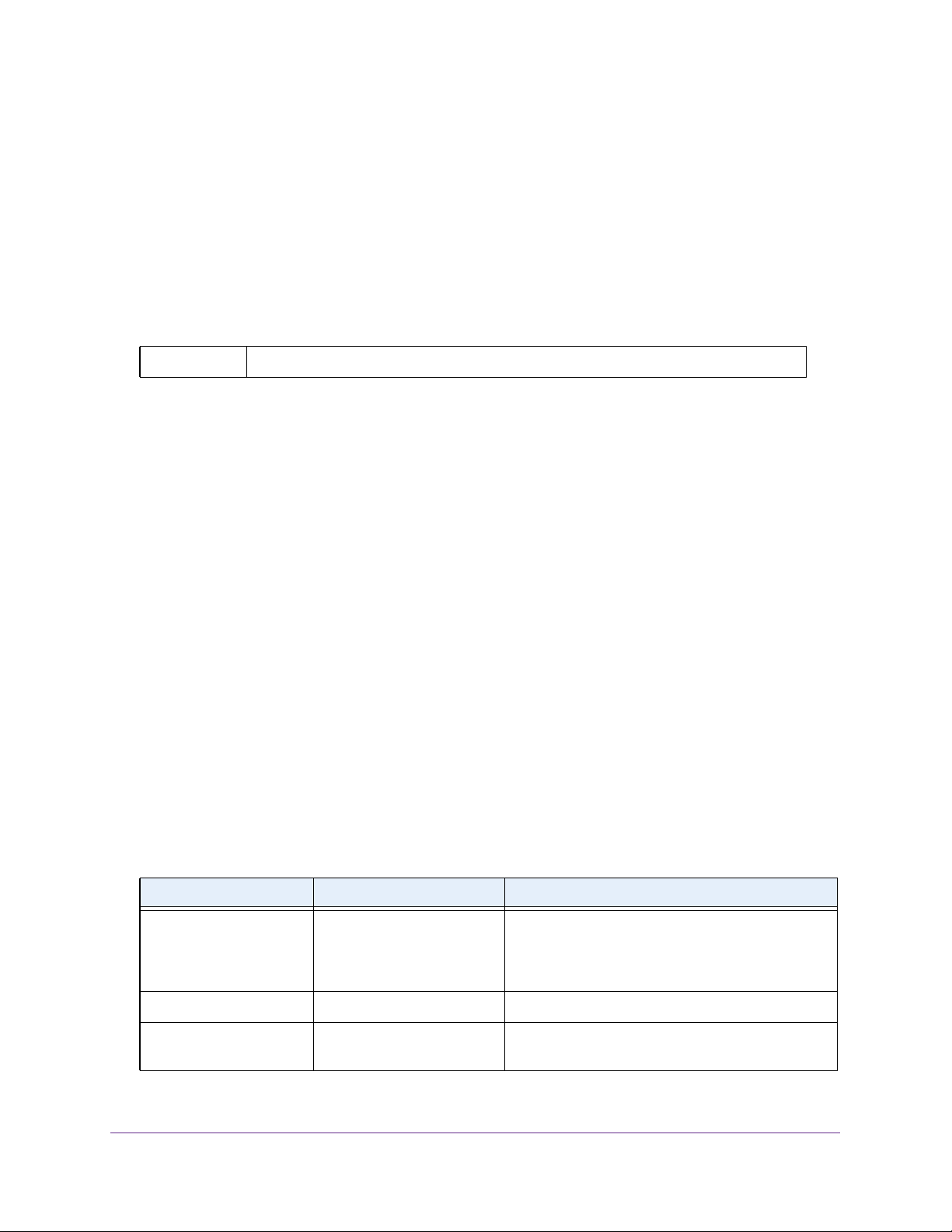
Format network parms ipaddr netmask [gateway]
• network parms is the command name.
• ipaddr and netmask are parameters and represent required values that you must enter
after you type the command keywords.
• [gateway] is an optional keyword, so you are not required to enter a value in place of
the keyword.
This command line reference manual lists each command by the command name and
provides a brief description of the command. Each command reference also contains the
following information:
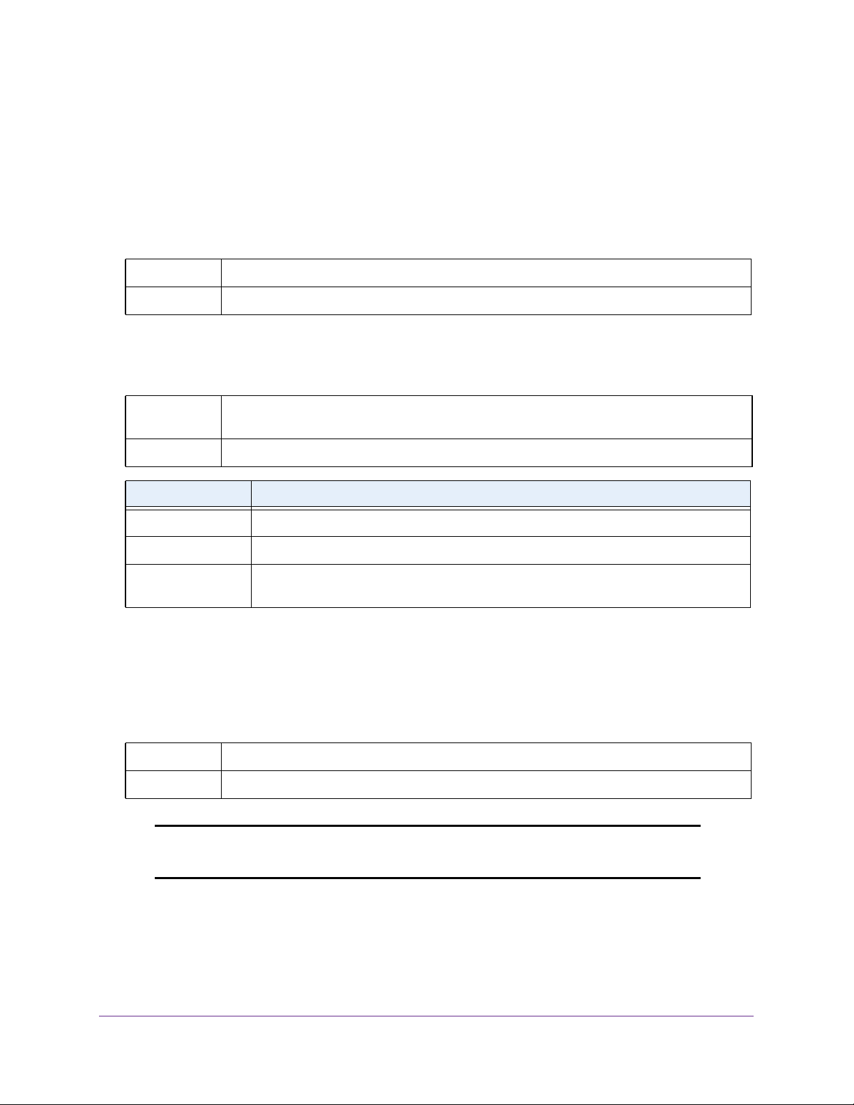
• Format shows the command keywords and the required and optional parameters.
• Mode identifies the command mode you must be in to access the command.
• Default shows the default value, if any, of a configurable setting on the device.
The show commands also contain a description of the information that the command shows.
Command Conventions
The parameters for a command might include mandatory values, optional values, or keyword
choices. Parameters are order-dependent. The following table describes the conventions this
document uses to distinguish between value types.
Table 1. Parameter Conventions
Symbol Example Description
italic font value or [value] Indicates a variable value. You must replace the
italicized text, which can be placed within curly
brackets or square brackets, with an appropriate
value, which might be a name or number.
[ ] square brackets [keyword] Indicates an optional parameter.
{ } curly braces {choice1 | choice2} Indicates that you must select a parameter from the
list of choices.
Using the Command-Line Interface
11
Page 12

M5300, M6100, and M7100 Series ProSAFE Managed Switches
Table 1. Parameter Conventions (continued)
Symbol Example Description
| Vertical bars choice1 | choice2 Separates the mutually exclusive choices.
[{ }] Braces within
square brackets
[{choice1 | choice2}] Indicates a choice within an optional element. This
format is used mainly for complicated commands
Common Parameter Values
Parameter values might be names (strings) or numbers. To use spaces as part of a name
parameter, enclose the name value in double quotes. For example, the expression “System
Name with Spaces” forces the system to accept the spaces. Empty strings (““) are not valid
user-defined strings. The following table describes common parameter values and value
formatting.
Table 2. Parameter Descriptions
Parameter Description
ipaddr This parameter is a valid IPv4 address. You can enter the IP address in the
following formats:
• a (32 bits)
• a.b (8.24 bits)
• a.b.c (8.8.16 bits)
• a.b.c.d (8.8.8.8)
In addition to these formats, the CLI accepts decimal, hexadecimal and octal
formats through the following input formats (where n is any valid hexadecimal, octal
or decimal number):
• 0xn (CLI assumes hexadecimal format.)
• 0n (CLI assumes octal format with leading zeros.)
• n (CLI assumes decimal format.)
ipv6-addr This parameter is a valid IPv6 address. You can enter the IP address in the
following formats:
• FE80:0000:0000:0000:020F:24FF:FEBF:DBCB
• FE80:0:0:0:20F:24FF:FEBF:DBCB
• FE80::20F24FF:FEBF:DBCB
• FE80:0:0:0:20F:24FF:128:141:49:32
For additional information, refer to RFC 3513.
Interface or
unit/slot/port
Logical Interface Represents a logical slot and port number. This is applicable in the case of a
Character strings Use double quotation marks to identify character strings, for example, “System
Valid slot and port number separated by a forward slash. For example, 0/1
represents slot number 0 and port number 1.
port-channel (LAG). You can use the logical unit/slot/port to configure the
port-channel.
Name with Spaces”. An empty string (“”) is not valid.
Using the Command-Line Interface
12
Page 13

M5300, M6100, and M7100 Series ProSAFE Managed Switches
unit/slot/port Naming Convention
NETGEAR Managed Switch software references physical entities such as cards and ports by
using a unit/slot/port naming convention. The NETGEAR Managed Switch software
also uses this convention to identify certain logical entities, such as Port-Channel interfaces.
The slot number has two uses. In the case of physical ports, it identifies the card containing
the ports. In the case of logical and CPU ports it also identifies the type of interface or port.
Table 3. Type of Slots
Slot Type Description
Physical slot numbers Physical slot numbers begin with zero, and are allocated up to the maximum
number of physical slots.
Logical slot numbers Logical slots immediately follow physical slots and identify port-channel
(LAG) or router interfaces. The value of logical slot numbers depend on the
type of logical interface and can vary from platform to platform.
CPU slot numbers The CPU slots immediately follow the logical slots.
The port identifies the specific physical port or logical interface being managed on a given
slot.
Table 4. Type of Ports
Port Type Description
Physical Ports The physical ports for each slot are numbered sequentially starting from one.
For example, port 1 on slot 0 (an internal port) for a switch is 1/0/1, port 2 is
1/0/2, port 3 is 1/0/3, and so on.
Logical Interfaces Port-channel or Link Aggregation Group (LAG) interfaces are logical
interfaces that are only used for bridging functions.
VLAN routing interfaces are only used for routing functions.
Loopback interfaces are logical interfaces that are always up.
Tunnel interfaces are logical point-to-point links that carry encapsulated
packets.
CPU ports CPU ports are handled by the driver as one or more physical entities located
on physical slots.
Note: In the CLI, loopback and tunnel interfaces do not use the
unit/slot/port format. To specify a loopback interface, you use
the loopback ID. To specify a tunnel interface, you use the tunnel ID.
Using the Command-Line Interface
13
Page 14

M5300, M6100, and M7100 Series ProSAFE Managed Switches
Using the No Form of a Command
The no keyword is a specific form of an existing command and does not represent a new or
distinct command. Almost every configuration command has a no form. In general, use the
no form to reverse the action of a command or reset a value back to the default. For example,
the no shutdown configuration command reverses the shutdown of an interface. Use the
command without the keyword no to reenable a disabled feature or to enable a feature that is
disabled by default. Only the configuration commands are available in the no form.
Executing Show Commands
All show commands can be issued from any configuration mode (Global Configuration,
Interface Configuration, VLAN Configuration, etc.). The show commands provide information
about system and feature-specific configuration, status, and statistics. Previously, show
commands could be issued only in User EXEC or Privileged EXEC modes.
CLI Output Filtering
Many CLI show commands include considerable content to display to the user. This can
make output confusing and cumbersome to parse through to find the information of desired
importance. The CLI Output Filtering feature allows the user, when executing CLI show
display commands, to optionally specify arguments to filter the CLI output to display only
desired information. The result is to simplify the display and make it easier for the user to find
the information the user is interested in.
The main functions of the CLI Output Filtering feature are:
• Pagination Control
- Supports enabling/disabling paginated output for all show CLI commands. When
disabled, output is displayed in its entirety. When enabled, output is displayed
page-by-page such that content does not scroll off the terminal screen until the user
presses a key to continue. --More-- or (q)uit is displayed at the end of each page.
- When pagination is enabled, press the return key to advance a single line, press q or
Q to stop pagination, or press any other key to advance a whole page. These keys
are not configurable.
Note: Although some NETGEAR Managed Switch show commands already
support pagination, the implementation is unique per command and
not generic to all commands.
• Output Filtering
- “Grep”-like control for modifying the displayed output to only show the user-desired
content.
- Filter displayed output to only include lines containing a specified string match.
Using the Command-Line Interface
14
Page 15

M5300, M6100, and M7100 Series ProSAFE Managed Switches
- Filter displayed output to exclude lines containing a specified string match.
- Filter displayed output to only include lines including and following a specified string
match.
- Filter displayed output to only include a specified section of the content (for example,
“interface 0/1”) with a configurable end-of-section delimiter.
- String matching should be case insensitive.
- Pagination, when enabled, also applies to filtered output.
The following shows an example of the extensions made to the CLI show commands for
the Output Filtering feature.
(NETGEAR Switch) #show running-config ?
<cr> Press enter to execute the command.
| Output filter options.
<scriptname> Script file name for writing active configuration.
all Show all the running configuration on the switch.
interface Display the running configuration for specificed interface
on the switch.
(NETGEAR Switch) #show running-config | ?
begin Begin with the line that matches
exclude Exclude lines that matches
include Include lines that matches
section Display portion of lines
For new commands for the feature, see CLI Output Filtering Commands on page 175.
Using the Command-Line Interface
15
Page 16

3. NETGEAR Managed Switch
Software Modules
NETGEAR Managed Switch software consists of flexible modules that can be applied in various
combinations to develop advanced Layer 2/3/4+ products. The commands and command modes
available on your switch depend on the installed modules. Additionally, for some show
commands, the output fields might change based on the modules included in the NETGEAR
Managed Switch software.
The NETGEAR Managed Switch software suite includes the following modules:
• Switching (Layer 2)
• Routing (Layer 3)
• IPv6 routing
• Multicast
• BGP-4
• Quality of Service
• Management (CLI, Web UI, and SNMP)
• IPv6 Management—Allows management of the NETGEAR Managed Switch device
through an IPv6 through an IPv6 address without requiring the IPv6 Routing package in
the system. The management address can be associated with the network port
(front-panel switch ports), a routine interface (port or VLAN) and the Service port.
3
• Metro
• Chassis management
• Data Center
• Secure Management
16
Page 17

M5300, M6100, and M7100 Series ProSAFE Managed Switches
Command Modes
The CLI groups commands into modes according to the command function. Each of the
command modes supports specific NETGEAR Managed Switch software commands. The
commands in one mode are not available until you switch to that particular mode, with the
exception of the User EXEC mode commands. You can execute the User EXEC mode
commands in the Privileged EXEC mode.
The command prompt changes in each command mode to help you identify the current
mode. The following table describes the command modes and the prompts visible in that
mode.
Note: The command modes available on your switch depend on the software
modules that are installed. For example, a switch that does not support
BGPv4 does not have the BGPv4 Router Command Mode.
Table 5. CLI Command Modes
Command Mode Prompt Mode Description
User EXEC Switch> Contains a limited set of commands to view
basic system information.
Privileged EXEC Switch# Allows you to issue any EXEC command,
enter the VLAN mode, or enter the Global
Configuration mode.
Global Config Switch (Config)# Groups general setup commands and
permits you to make modifications to the
running configuration.
VLAN Config Switch (Vlan)# Groups all the VLAN commands.
Interface Config Switch (Interface
unit/slot/port)#
Switch (Interface Loopback id)#
Switch (Interface Tunnel id)#
Switch (Interface unit/slot/port
(startrange)-unit/slot/port
(endrange)#
Manages the operation of an interface and
provides access to the router interface
configuration commands.
Use this mode to set up a physical port for a
specific logical connection operation.
Use this mode to manage the operation of a
range of interfaces. For example the prompt
may display as follows:
Switch (Interface 1/0/1-1/0/4) #
Switch (Interface lag
lag-intf-num)#
Switch (Interface vlan vlan-id)# Enters VLAN routing interface configuration
NETGEAR Managed Switch Software Modules
17
Enters LAG Interface configuration mode for
the specified LAG.
mode for the specified VLAN ID.
Page 18

M5300, M6100, and M7100 Series ProSAFE Managed Switches
Table 5. CLI Command Modes (continued)
Command Mode Prompt Mode Description
Line Console Switch (config-line)# Contains commands to configure outbound
telnet settings and console interface
settings, as well as to configure console
login/enable authentication.
Line SSH Switch (config-ssh)# Contains commands to configure SSH
login/enable authentication.
Line Telnet Switch (config-telnet)# Contains commands to configure telnet
login/enable authentication.
AAA IAS User
Config
Mail Server Config Switch (Mail-Server)# Allows configuration of the email server.
Policy Map Config Switch (Config-policy-map)# Contains the QoS Policy-Map configuration
Policy Class Config Switch(Config-policy-class-map)# Consists of class creation, deletion, and
Class Map Config Switch (Config-class-map)# Contains the QoS class map configuration
Ipv6_Class-Map
Config
Router OSPF
Config
Router OSPFv3
Config
Router RIP Config Switch (Config-router)# Contains the RIP configuration commands.
BGP Router Config Switch (Config-router)# Contains the BGP4 configuration
Switch (Config-IAS-User)# Allows password configuration for a user in
the IAS database.
commands.
matching commands. The class match
commands specify Layer 2, Layer 3, and
general match criteria.
commands for IPv4.
Switch (Config-class-map)# Contains the QoS class map configuration
commands for IPv6.
Switch (Config-router)# Contains the OSPF configuration
commands.
Switch (Config rtr)# Contains the OSPFv3 configuration
commands.
commands.
Route Map Config Switch (config-route-map)# Contains the route map configuration
commands.
IPv6 Address
Family Config
Peer Template
Config
MAC Access-list
Config
Switch (Config-router-af)# Contains the IPv6 address family
configuration commands.
(Config-rtr-tmplt)# Contains the BGP peer template
configuration commands.
Switch (Config-mac-access-list)# Allows you to create a MAC Access-List and
to enter the mode containing MAC
Access-List configuration commands.
NETGEAR Managed Switch Software Modules
18
Page 19

M5300, M6100, and M7100 Series ProSAFE Managed Switches
Table 5. CLI Command Modes (continued)
Command Mode Prompt Mode Description
TACACS Config Switch (Tacacs)# Contains commands to configure properties
for the TACACS servers.
DHCP Pool
Config
DHCPv6 Pool
Config
Chassis Global
Config Mode
ARP Access-List
Config Mode
Support Mode Switch (Support)# Allows access to the support commands,
Switch (Config dhcp-pool)# Contains the DHCP server IP address pool
configuration commands.
Switch (Config dhcp6-pool)# Contains the DHCPv6 server IPv6 address
pool configuration commands.
Switch (Config chassis)# Allows you to access the Chassis Global
Config Mode.
Switch (Config-arp-access-list)# Contains commands to add ARP ACL rules
in an ARP Access List.
which should only be used by the
manufacturer's technical support personnel
as improper use could cause unexpected
system behavior and/or invalidate product
warranty.
The following table explains how to enter or exit each mode.
Table 6. CLI Mode Access and Exit
Command Mode Access Method Exit or Access Previous Mode
User EXEC This is the first level of access. To exit, enter logout.
Privileged EXEC From the User EXEC mode, enter
enable.
Global Config From the Privileged EXEC mode, enter
configure.
VLAN Config From the Privileged EXEC mode, enter
vlan database.
NETGEAR Managed Switch Software Modules
To exit to the User EXEC mode, enter exit or
press
Ctrl-Z.
To exit to the Privileged EXEC mode, enter
exit, or press Ctrl-Z.
To exit to the Privileged EXEC mode, enter
exit, or press Ctrl-Z.
19
Page 20

M5300, M6100, and M7100 Series ProSAFE Managed Switches
Table 6. CLI Mode Access and Exit (continued)
Command Mode Access Method Exit or Access Previous Mode
Interface Config From the Global Config mode, enter:
interface unit/slot/port
From the Global Config mode, enter:
interface loopback id
From the Global Config mode, enter:
interface tunnel id
From the Global Config mode, enter:
interface
unit/slot/port(startrange)-
unit/slot/port(endrange)
From the Global Config mode, enter:
interface lag lag-intf-num
To exit to the Global Config mode, enter exit.
To return to the Privileged EXEC mode, enter
Ctrl-Z.
From the Global Config mode, enter:
interface vlan vlan-id
Line Console From the Global Config mode, enter
line console.
Line SSH From the Global Config mode, enter
line ssh.
Line Telnet From the Global Config mode, enter
line telnet.
AAA IAS User
Config
Mail Server Config From the Global Config mode, enter
Policy-Map
Config
Policy-Class-Map
Config
From the Global Config mode, enter
aaa ias-user username name.
mail-server address.
From the Global Config mode, enter
policy-map.
From the Policy Map mode enter class. To exit to the Policy Map mode, enter exit. To
To exit to the Global Config mode, enter exit.
To return to the Privileged EXEC mode, enter
Ctrl-Z.
To exit to the Global Config mode, enter exit.
To return to the Privileged EXEC mode, enter
Ctrl-Z.
To exit to the Global Config mode, enter exit.
To return to the Privileged EXEC mode, enter
Ctrl-Z.
To exit to the Global Config mode, enter exit.
To return to the Privileged EXEC mode, enter
Ctrl-Z.
To exit to the Global Config mode, enter exit.
To return to the Privileged EXEC mode, enter
Ctrl-Z.
To exit to the Global Config mode, enter exit.
To return to the Privileged EXEC mode, enter
Ctrl-Z.
return to the Privileged EXEC mode, enter
Ctrl-Z.
Class-Map
Config
From the Global Config mode, enter
class-map, and specify the optional
keyword
protocol for this class. See
page 1045 for more information.
ipv4 to specify the Layer 3
class-map on
NETGEAR Managed Switch Software Modules
20
To exit to the Global Config mode, enter exit.
To return to the Privileged EXEC mode, enter
Ctrl-Z.
Page 21

M5300, M6100, and M7100 Series ProSAFE Managed Switches
Table 6. CLI Mode Access and Exit (continued)
Command Mode Access Method Exit or Access Previous Mode
VPC From Global Config mode, enter vpc. To exit to the Global Config mode, enter exit.
To return to the Privileged EXEC mode, enter
Ctrl-Z.
Ipv6-Class-Map
Config
Router OSPF
Config
Router OSPFv3
Config
Router RIP
Config
BGP Router
Config
Route Map Config From the Global Config mode, enter
IPv6 Address
Family Config
From the Global Config mode, enter
class-map and specify the optional
keyword
protocol for this class. See
page 1045 for more information.
From the Global Config mode, enter
router ospf.
From the Global Config mode, enter
ipv6 router ospf.
From the Global Config mode, enter
router rip.
From the Global Config mode, enter
router bgp asnumber.
route-map map-tag.
From the BGP Router Config mode,
enter
ipv6 to specify the Layer 3
class-map on
address-family ipv6.
To exit to the Global Config mode, enter exit.
To return to the Privileged EXEC mode, enter
Ctrl-Z.
To exit to the Global Config mode, enter exit.
To return to the Privileged EXEC mode, enter
Ctrl-Z.
To exit to the Global Config mode, enter exit.
To return to the Privileged EXEC mode, enter
Ctrl-Z.
To exit to the Global Config mode, enter exit.
To return to the Privileged EXEC mode, enter
Ctrl-Z.
To exit to the Global Config mode, enter exit.
To return to the Privileged EXEC mode, enter
Ctrl-Z.
To exit to the Global Config mode, enter exit.
To return to the Privileged EXEC mode, enter
Ctrl-Z.
To exit to the Global Config mode, enter exit.
To return to the Privileged EXEC mode, enter
Ctrl-Z.
Peer Template
Config
MAC Access-list
Config
TACACS Config From the Global Config mode, enter
DHCP Pool
Config
DHCPv6 Pool
Config
From the BGP Router Config mode,
enter
template peer name to create
a BGP peer template and enter Peer
Template Configuration mode.
From the Global Config mode, enter
mac access-list extended name.
tacacs-server host ip-addr,
where ip-addr is the IP address of the
TACACS server on your network.
From the Global Config mode, enter
ip dhcp pool pool-name.
From the Global Config mode, enter
ip dhcpv6 pool pool-name.
NETGEAR Managed Switch Software Modules
21
o exit to the Global Config mode, enter exit. T o
return to the Privileged EXEC mode, enter
Ctrl-Z.
To exit to the Global Config mode, enter exit.
To return to the Privileged EXEC mode, enter
Ctrl-Z.
To exit to the Global Config mode, enter exit.
To return to the Privileged EXEC mode, enter
Ctrl-Z.
To exit to the Global Config mode, enter exit.
To return to the Privileged EXEC mode, enter
Ctrl-Z.
To exit to the Global Config mode, enter exit.
To return to the Privileged EXEC mode, enter
Ctrl-Z.
Page 22

M5300, M6100, and M7100 Series ProSAFE Managed Switches
Table 6. CLI Mode Access and Exit (continued)
Command Mode Access Method Exit or Access Previous Mode
Chassis Global
Config Mode
ARP Access-List
Config Mode
Support Mode From the Privileged EXEC mode, enter
From the Global Config mode, enter
chassis.
From the Global Config mode, enter arp
access-list
support.
Note: The support command is
available only if the techsupport
enable command has been issued.
.
To exit to the Global Config mode, enter the
exit command. To return to the Privileged
EXEC mode, enter
To exit to the Global Config mode, enter the
exit command. To return to the Privileged
EXEC mode, enter
To exit to the Privileged EXEC mode, enter
exit, or press Ctrl-Z.
Ctrl-Z.
Ctrl-Z.
Command Completion and Abbreviation
Command completion finishes spelling the command when you type enough letters of a
command to uniquely identify the command keyword. Once you have entered enough letters,
press the SPACEBAR or TAB key to complete the word.
Command abbreviation allows you to execute a command when you have entered there are
enough letters to uniquely identify the command. You must enter all of the required keywords
and parameters before you enter the command.
CLI Error Messages
If you enter a command and the system is unable to execute it, an error message appears.
The following table describes the most common CLI error messages.
Table 7. CLI Error Messages
Message Text Description
% Invalid input detected at
'^' marker.
Command not found / Incomplete
command. Use ? to list
commands.
Ambiguous command Indicates that you did not enter enough letters to uniquely identify the
Indicates that you entered an incorrect or unavailable command. The
carat (^) shows where the invalid text is detected. This message also
appears if any of the parameters or values are not recognized.
Indicates that you did not enter the required keywords or values.
command.
NETGEAR Managed Switch Software Modules
22
Page 23

M5300, M6100, and M7100 Series ProSAFE Managed Switches
CLI Line-Editing Conventions
The following table describes the key combinations you can use to edit commands or
increase the speed of command entry. You can access this list from the CLI by entering
from the User or Privileged EXEC modes.
Table 8. CLI Editing Conventions
Key Sequence Description
DEL or Backspace Delete previous character.
Ctrl-A Go to beginning of line.
Ctrl-E Go to end of line.
Ctrl-F Go forward one character.
Ctrl-B Go backward one character.
Ctrl-D Delete current character.
help
Ctrl-U, X Delete to beginning of line.
Ctrl-K Delete to end of line.
Ctrl-W Delete previous word.
Ctrl-T Transpose previous character.
Ctrl-P Go to previous line in history buffer.
Ctrl-R Rewrites or pastes the line.
Ctrl-N Go to next line in history buffer.
Ctrl-Y Prints last deleted character.
Ctrl-Q Enables serial flow.
Ctrl-S Disables serial flow.
Ctrl-Z Return to root command prompt.
Tab, <SPACE> Command-line completion.
Exit Go to next lower command prompt.
? List available commands, keywords, or parameters.
NETGEAR Managed Switch Software Modules
23
Page 24

M5300, M6100, and M7100 Series ProSAFE Managed Switches
Using CLI Help
Enter a question mark (?) at the command prompt to display the commands available in the
current mode.
(NETGEAR Switch) >?
enable Enter into user privilege mode.
help Display help for various special keys.
logout Exit this session. Any unsaved changes are lost.
password Change an existing user’s password.
ping Send ICMP echo packets to a specified IP address.
quit Exit this session. Any unsaved changes are lost.
show Display Switch Options and Settings.
telnet Telnet to a remote host.
Enter a question mark (?) after each word you enter to display available command keywords
or parameters.
(NETGEAR Switch) #network ?
ipv6 Configure IPv6 parameters for system network.
javamode Enable/Disable.
mac-address Configure MAC Address.
mac-type Select the locally administered or burnedin MAC
address.
mgmt_vlan Configure the Management VLAN ID of the switch.
parms Configure Network Parameters of the device.
protocol Select DHCP, BootP, or None as the network config
protocol.
If the help output shows a parameter in angle brackets, you must replace the parameter with
a value.
(NETGEAR Switch) #network parms ?
<ipaddr> Enter the IP Address.
none Reset IP address and gateway on management interface
If there are no additional command keywords or parameters, or if additional parameters are
optional, the following message appears in the output:
<cr> Press Enter to execute the command
You can also enter a question mark (?) after typing one or more characters of a word to list
the available command or parameters that begin with the letters, as shown in the following
example:
(NETGEAR Switch) #show m?
mac mac-addr-table mac-address-table
mail-server mbuf monitor
NETGEAR Managed Switch Software Modules
24
Page 25

M5300, M6100, and M7100 Series ProSAFE Managed Switches
Accessing the CLI
You can access the CLI by using a direct console connection or by using a telnet or SSH
connection from a remote management host.
For the initial connection, you must use a direct connection to the console port. You cannot
access the system remotely until the system has an IP address, subnet mask, and default
gateway. You can set the network configuration information manually, or you can configure
the system to accept these settings from a BootP or DHCP server on your network. For more
information, see
Network Interface Commands on page 72.
NETGEAR Managed Switch Software Modules
25
Page 26

4. Chassis Commands
4
This chapter describes the chassis commands available in the NETGEAR Managed Switch CLI.
Note: These commands apply to the M6100 series switches only.
The Chassis Commands chapter includes the following sections:
• General Chassis Commands
• Backplane Port Commands
• Chassis Firmware Synchronization Commands
• Nonstop Forwarding Commands for Chassis Configuration
The commands in this chapter are in one of two functional groups:
• Show commands. Display switch settings, statistics, and other information.
• Configuration commands. Configure features and options of the switch. For every
configuration command, there is a show command that displays the configuration setting.
26
Page 27
M5300, M6100, and M7100 Series ProSAFE Managed Switches
General Chassis Commands
This section describes the commands you use to configure the chassis.
chassis
This command sets the mode to Chassis Global Config.
Format chassis
Mode Chassis Global Config
chassis-status sample-mode
This command set the global status management mode.
Format chassis-status sample-mode [cumulative | history [max-samples
<100-500>]]
Mode Chassis Global Config
Parameter Description
cumulative Tracks the sum of received time stamp offsets cumulatively.
history Tracks the history of received timestamps.
max-samples As an option for the history parameter, the maximum number of samples to keep. The
valid range is from 100 to 500.
member (Chassis Global Config)
This command configures a blade. The unit is the identifier of the blade that you want to
add or remove from the chassis. The switchindex is the index into the database of the
supported blade types, indicating the type of the blade that is being preconfigured. The blade
index is a 32-bit integer. You execute this command on the management blade.
Format member unit switchindex
Mode Chassis Global Config
Note: You can obtain the switch index by executing the show supported
switchtype command in user EXEC mode.
Chassis Commands
27
Page 28

M5300, M6100, and M7100 Series ProSAFE Managed Switches
no member
This command removes a blade from the chassis. The unit is the identifier of the blade to
be removed from the chassis. You execute this command on the primary management blade.
Format no member unit
Mode Chassis Global Config
movemanagement (Chassis Global Config)
This command moves the management functionality from one blade to the other. The
fromunit is the identifier of the current management blade. The tounit is the identifier of
the new management blade. Upon execution, the entire chassis (including all interfaces in
the chassis) is unconfigured and reconfigured with the configuration on the new management
blade. After the reload is complete, you must perform all chassis management capabilities on
the new management blade. To preserve the current configuration across a management
blade move, execute the copy system:running-config nvram:startup-config
privileged EXEC command or save privileged EXEC command before you perform the
management blade move. A management blade move causes all routes and layer 2
addresses to be lost. You execute this command is executed on the management blade. The
system prompts you to confirm the management blade move.
Note: You can only configure the blade in slot 1 or slot 2 as a management
blade.
Format movemanagement fromunit tounit
Mode Chassis Global Config
slot (for chassis configuration)
This command configures a slot in the system. The unit/slot is the slot identifier of the
slot. The cardindex is the index into the database of the supported card types, indicating
the type of the card being preconfigured in the specified slot. The card index is a 32-bit
integer. If a card is currently present in the slot that is unconfigured, the configured
information will be deleted and the slot will be reconfigured with default information for the
card.
Format slot unit/slot cardindex
Mode Global Config
Note: Card index can be obtained by executing show supported cardtype
command in User EXEC mode.
Chassis Commands
28
Page 29

M5300, M6100, and M7100 Series ProSAFE Managed Switches
no slot
This command removes configured information from an existing slot in the system.
Format no slot unit/slot cardindex
Mode Global Config
Note: Card index can be obtained by executing show supported cardtype
command in User EXEC mode.
set slot disable (for chassis configuration)
This command configures the administrative mode of the slot(s). If you specify all, the
command is applied to all slots, otherwise the command is applied to the slot identified by
unit/slot.
If a card or other module is present in the slot, this administrative mode will effectively be
applied to the contents of the slot. If the slot is empty , this administrative mode will be applied
to any module that is inserted into the slot. If a card is disabled, all the ports on the device are
operationally disabled and shown as “unplugged” on management screens.
Format set slot disable [unit/slot] | all]
Mode Global Config
no set slot disable
This command unconfigures the administrative mode of the slot or slots. If you specify all,
the command removes the configuration from all slots, otherwise the configuration is
removed from the slot identified by unit/slot.
If a card or other module is present in the slot, this administrative mode removes the
configuration from the contents of the slot. If the slot is empty, this administrative mode
removes the configuration from any module inserted into the slot. If a card is disabled, all the
ports on the device are operationally disabled and shown as “unplugged” on management
screens.
Format no set slot disable [unit/slot] | all]
Mode Global Config
set slot power (for chassis configuration)
This command configures the power mode of the slot(s) and allows power to be supplied to a
card located in the slot. If you specify all, the command is applied to all slots, otherwise the
command is applied to the slot identified by unit/slot.
Chassis Commands
29
Page 30

M5300, M6100, and M7100 Series ProSAFE Managed Switches
Use this command when installing or removing cards. If a card or other module is present in
this slot, the power mode is applied to the contents of the slot. If the slot is empty, the power
mode is applied to any card inserted into the slot.
Format set slot power [unit/slot] | all]
Mode Global Config
no set slot power
This command unconfigures the power mode of the slot or slots and prohibits power from
being supplied to a card located in the slot. If you specify all, the command prohibits power
to all slots, otherwise the command prohibits power to the slot identified by unit/slot.
Use this command when installing or removing cards. If a card or other module is present in
this slot, power is prohibited to the contents of the slot. If the slot is empty , power is prohibited
to any card inserted into the slot.
Format no set slot power [unit/slot] | all]
Mode Global Config
reload (for chassis configuration)
This command resets the entire chassis or the identified blade. The blade is the blade
identifier. The system prompts you to confirm that you want to reset the chassis or blade.
Format reload [blade]
Mode Global Config
show supported cardtype (for chassis configuration)
This commands displays information about all card types or specific card types supported in
the system.
Format show supported cardtype [cardindex]
Mode User EXEC
If you do not supply a value for cardindex, the following output appears:
Term Definition
Card Index (CID) The index into the database of the supported card types. This index is used when
preconfiguring a slot.
Card Model
Identifier
The model identifier for the supported card type.
Chassis Commands
30
Page 31

M5300, M6100, and M7100 Series ProSAFE Managed Switches
If you supply a value for cardindex, the following output appears:
Term Definition
Card Type The 32-bit numeric card type for the supported card.
Model Identifier The model identifier for the supported card type.
Card Description The description for the supported card type.
show chassis
This command displays chassis status information about all blades in the chassis or, if you
specify the unit value, about a single blade. For blades that would normally be allowed to
join the chassis but do not have a matching chassis template ID, the blade status is shown as
STM Mismatch.
Format show chassis [unit]
Mode Privileged EXEC
Term Definition
Unit The unit identifier assigned to the blade.
If you do not specify a value for unit, the following information displays:
Term Definition
Management Role Indicates whether the blade is the supervisor blade, a member blade, or an operational
backup blade, or whether the status is unassigned.
Preconfigured
Model Identifier
Plugged-In Model IDThe model identifier of the blade in the chassis. The Model Identifier is a 32-character field
Switch Status The chassis status. Possible values for this state are: OK, Unsupported, Code Mismatch,
The model identifier of a preconfigured blade that is ready to join the chassis. The Model
Identifier is a 32-character field that is assigned by the device manufacturer to identify the
device.
that is assigned by the device manufacturer to identify the device.
SDM Mismatch, Config Mismatch, or Not Present. A mismatch indicates that a blade is
running a different software version, has a different SDM template, or has a different
configuration from the management blade. The SDM Mismatch status indicates that the
blade joined the chassis, but has a different SDM template than the management blade.
This status is temporary; the blade automatically reloads using the template of the chassis
manager.
If a chassis firmware synchronization operation is in progress, the status is shown as
Updating Code.
Code Version The detected version of code on this blade.
Chassis Commands
31
Page 32

M5300, M6100, and M7100 Series ProSAFE Managed Switches
Command example:
(NETGEAR Switch) #show chassis
Management Plugged-in Serial Switch Version Admin PoE
Unit Role Model ID Number Status Code State Card
------ ---------- ------------ ------------- ------------- ----------- ------- -------1 Primary XCM8944-PoE+ 33J1245WF0021 OK 5.26.23.31 Enable XCM89P
2 Oper Standby XCM8948-uPoE 33J1245WF0022 CodeMismatch 5.26.23.31 Enable XCM89UP
3 Chassis Mbr XCM8924X 33J1245WF0023 NoPwr 5.26.23.31 Enable N/
A
If you specify a value for unit, the following information displays.
Term Definition
Unit The unit number of the blade.
Management
Status
Hardware
Management
Indicates whether the blade is the supervisor blade, the backup blade, a member blade, or
unassigned.
The hardware management preference of the blade. The hardware management
preference can be disabled or unassigned.
Preference
Admin
Management
Preference
The administrative management preference value that is assigned to the blade. This
preference value indicates how likely the blade is to be selected as the primary
management blade.
Admin State Administrative state of the blade.
Power State Power state of the blade.
Switch Type The 32-bit numeric blade type.
Plugged-in Model
Identifier
The model identifier of the blade in the chassis. The Model Identifier is a 32-character field
that is assigned by the device manufacturer to identify the device.
Switch Status The blade status. Possible values are OK, Unsupported, Code Mismatch, Config
Mismatch, SDM Mismatch, or Not Present.
A mismatch indicates that the blade is running a different version of the code, SDM
template, or configuration than the management blade. The SDM Mismatch status
indicates that the blade is part of the chassis, but is running a different SDM template than
the management blade. A mismatch status is temporary; the blade automatically reloads
using the template that is running on the management blade. If a chassis firmware
synchronization operation is in progress, the status is shown as Updating Code.
Switch Description The blade description.
Detected Code in
Flash
The version of code that is currently stored in FLASH memory on the blade. This code
executes after the blade is reset. If the blade is not present and the data is from
preconfiguration, then the code version is “None”.
POE D-Card
The description of the PoE daughter card that is plugged into the blade.
description
POE D-Card PoE
firmware version
The firmware version that is running on the PoE controller of the daughter card that is
plugged into the blade.
Chassis Commands
32
Page 33

M5300, M6100, and M7100 Series ProSAFE Managed Switches
Term Definition
CPLD Version The version of CPLD firmware that is running on the blade.
SFS Last Attempt
Status
Serial Number The serial number for the blade.
Up Time The system up time.
The chassis firmware synchronization status in the last attempt for the blade.
Command example:
(NETGEAR Switch) #show chassis 1
Switch............................ 1
Management Status................. Management Switch
Hardware Management Preference.... Unassigned
Admin Management Preference....... 15
Admin State....................... Enable
Power State....................... Enable
Switch Type....................... 0x4320004
Preconfigured Model Identifier.... XCM8948
Plugged-in Model Identifier....... XCM8948
Switch Status..................... OK
Switch Description................ XCM8948 ProSafe 48-port Gigabit blade
Detected Code in Flash............ 5.26.23.31
CPLD version ............ ........ 0x01
POE D-card Description............ XCM89UP ProSafe UPoE daughter card
POE D-card PoE FW version....... 1.0
SFS Last Attempt Status........... None
Serial Number..................... 33J1245WF0021
Up Time........................... 4 days 21 hrs 52 mins 51 secs
Command example:
(NETGEAR Switch) #show chassis 2
Switch............................ 2
Management Status................. Standby Management unit
Hardware Management Preference.... Unassigned
Admin Management Preference....... 14
Admin State....................... Enable
Power State....................... Enable
Switch Type....................... 0x5320005
Preconfigured Model Identifier.... XCM8948
Plugged-in Model Identifier....... XCM8948
Switch Status..................... OK
Switch Description................ XCM8948 ProSafe 48-port Gigabit blade
Detected Code in Flash............ 5.26.23.31
Chassis Commands
33
Page 34

M5300, M6100, and M7100 Series ProSAFE Managed Switches
CPLD version ............ ........ 0x01
POE D-card Description............ XCM89P ProSafe PoE+ daughter card
POE D-card PoE FW version....... 1.0
SFS Last Attempt Status........... None
Serial Number..................... 33J1245WF0022
Up Time........................... 4 days 21 hrs 52 mins 41 secs
Command example:
(NETGEAR Switch) #show chassis 3
Switch............................ 3
Management Status................. Chassis Member
Hardware Management Preference.... Unassigned
Admin Management Preference....... Disabled
Admin State....................... Enable
Power State....................... Enable
Switch Type....................... 0x4320004
Preconfigured Model Identifier.... XCM8948
Plugged-in Model Identifier....... XCM8948
Switch Status..................... OK
Switch Description................ XCM8948 ProSafe 48-port Gigabit blade
Detected Code in Flash............ 5.26.23.31
CPLD version ............ ........ 0x01
POE D-card Description............ Not Installed
POE D-card PoE FW version....... NA
SFS Last Attempt Status........... None
Serial Number..................... 2X61295V00008
Up Time........................... 4 days 21 hrs 56 mins 25 secs
show chassis watchdog
This command shows the internal watchdog timer on the switch, which reboots the switch if
the CPU becomes stuck or does not respond.
Format show chassis watchdog
Mode Privileged EXEC
Command example:
(NETGEAR Switch)# show chassis watchdog
Slot Watchdog counter
1 0
2 1
3 0
Chassis Commands
34
Page 35

M5300, M6100, and M7100 Series ProSAFE Managed Switches
show chassis-status
Every two seconds, a blade broadcasts heartbeat messages. A state table on the supervisor
and each blade tracks every unit in the chassis. The table maintains a running history of the
heartbeat messages, current observed interval, and the minimum, maximum, and average
observed times between heartbeat messages. Sequence numbers in the discovery
messaged determine loss.
Format chassis-status unit [unit | all] [clear]
Mode User EXEC
Command example:
(NETGEAR Switch) #show chassis-status 1
Chassis Unit 1 Status
Unit Current Average Min Max Dropped
1 2000 2000 2000 2000 0
2 2000 2100 2000 2500 0
3 2000 2100 2000 2200 0
show supported switchtype (for chassis configuration)
This commands displays information about all supported switch types or a specific switch
type.
Format show supported switchtype [switchindex]
Mode User EXEC
Privileged EXEC
If you do not supply a value for switchindex, the following output appears:
Term Definition
Switch Index (SID) The index into the database of supported blade types. This index is used when you
preconfigure a member to be added to the chassis.
Model Identifier The model identifier for the supported blade type.
Management
Preference
Code Version The code load target identifier of the blade type.
The management preference value of the blade type.
Chassis Commands
35
Page 36

M5300, M6100, and M7100 Series ProSAFE Managed Switches
If you supply a value for switchindex, the following output appears:
Term Definition
Switch Type The 32-bit numeric switch type for the supported blade.
Model Identifier The model identifier for the supported blade type.
Switch Description The description for the supported blade type.
Backplane Port Commands
This section describes the commands you use to view and configure backplane port
information.
show backplane-port
This command displays summary backplane-port information for all interfaces.
Format show backplane-port
Mode Privileged EXEC
For each Interface:
Term Definition
Unit The blade number.
Interface The blade and port numbers.
Link Status Status of the link.
Link Speed Speed (Gbps) of the blade port link.
show backplane-port counters
This command displays summary data counter information for all interfaces.
Format show backplane-port counters
Mode Privileged EXEC
Term Definition
Unit The slot number.
Interface The slot and port numbers.
Tx Data Rate Trashing data rate in megabits per second on the backplane port.
Tx Error Rate Platform-specific number of transmit errors per second.
Chassis Commands
36
Page 37

M5300, M6100, and M7100 Series ProSAFE Managed Switches
Term Definition
Tx Total Errors Platform-specific number of total transmit errors since power-up.
Rx Data Rate Receive data rate in megabits per second on the backplane port.
Rx Error Rate Platform-specific number of receive errors per second.
Rx Total Errors Platform-specific number of total receive errors since power-up.
Link Flaps The number of times this backplane port transitioned to the down state.
show backplane-port diag
This command shows backplane port diagnostics for each port and is only intended for Field
Application Engineers (FAEs) and developers. An F AE will advise on the necessity to run this
command and capture this information.
Format show backplane-port diag [<1-3> | all] [verbose]
Mode Privileged EXEC
show backplane-port packet-path
This command displays the route a packet will take to reach the destination.
Format show backplane-port packet-path {1-3 | all}
Mode Privileged EXEC
show backplane
This command displays the backplane model ID, FAPGA version, and serial number.
Format show backplane
Mode Privileged EXEC
Chassis Firmware Synchronization Commands
Chassis Firmware Synchronization (CFS) provides the ability to automatically synchronize
firmware for all chassis members. If a blade joins the chassis and its firmware version is
different from the version running on the chassis manager, the CFS feature can either
upgrade or downgrade the firmware on the mismatched chassis member. There is no attempt
to synchronize the blade to the latest firmware in the chassis.
Chassis Commands
37
Page 38

M5300, M6100, and M7100 Series ProSAFE Managed Switches
boot auto-copy-sw (for chassis firmware synchronization)
Use this command to enable the Chassis Firmware Synchronization feature on the chassis.
Default Disabled
Format boot auto-copy-sw
Mode Privileged Exec
no boot auto-copy-sw
Use this command to disable the Chassis Firmware Synchronization feature on the chassis.
Format no boot auto-copy-sw
Mode Privileged Exec
boot auto-copy-sw trap (for chassis firmware synchronization)
Use this command to enable the sending of SNMP traps that are related to the Chassis
Firmware Synchronization feature.
Default Enabled
Format boot auto-copy-sw trap
Mode Privileged Exec
no boot auto-copy-sw trap
Use this command to disable the sending of traps that are related to the Chassis Firmware
Synchronization feature.
Format no boot auto-copy-sw trap
Mode Privileged Exec
boot auto-copy-sw allow-downgrade (for chassis firmware synchronization)
Use this command to allow the chassis manager to downgrade the firmware version on the
chassis member if the firmware version on the manager is older than the firmware version on
the chassis member.
Default Enabled
Format boot auto-copy-sw allow-downgrade
Mode Privileged Exec
Chassis Commands
38
Page 39

M5300, M6100, and M7100 Series ProSAFE Managed Switches
no boot auto-copy-sw allow-downgrade
Use this command to prevent the chassis manager from downgrading the firmware version of
a chassis member.
Format no boot auto-copy-sw allow-downgrade
Mode Privileged Exec
show auto-copy-sw (for chassis firmware synchronization)
Use this command to display chassis firmware synchronization configuration status
information.
Format show auto-copy-sw
Mode Privileged Exec
Term Definition
Synchronization Shows whether the CFS feature is enabled.
SNMP Trap Status Shows whether the chassis will send traps for CFS events.
Allow Downgrade Shows wether the manager is permitted to downgrade the firmware version of a
chassis member.
Nonstop Forwarding Commands for Chassis Configuration
Note: Nonstop forwarding (NSF) is enabled by default on the chassis. You
cannot disable NSF on the chassis.
A switch can be described in terms of three semi-independent functions called the forwarding
plane, the control plane, and the management plane. The forwarding plane forwards data
packets. The forwarding plane is implemented in hardware. The control plane is the set of
protocols that determine how the forwarding plane should forward packets, deciding which
data packets are allowed to be forwarded and where they should go. Application software on
the management blade acts as the control plane. The management plane is application
software running on the management blade that provides interfaces allowing a network
administrator to configure and monitor the device.
NSF allows the forwarding plane of chassis blades to continue to forward packets while the
control and management planes restart as a result of a power failure, hardware failure, or
software fault on the management blade. A nonstop forwarding failover can also be manually
initiated using the initiate failover command. Traffic flows that enter and exit the
Chassis Commands
39
Page 40

M5300, M6100, and M7100 Series ProSAFE Managed Switches
chassis through physical ports on a blade other than the management blade continue with at
most subsecond interruption when the management blade fails.
To prepare the backup management blade in case of a failover, applications on the
management blade continuously checkpoint some state information to the backup blade.
Changes to the running configuration are automatically copied to the backup blade. MAC
addresses stay the same across a nonstop forwarding failover so that neighbors do not have
to relearn them.
When a nonstop forwarding failover occurs, the control plane on the backup blade starts from
a partially-initialized state and applies the checkpointed state information. While the control
plane is initializing, the chassis cannot react to external changes, such as network topology
changes. Once the control plane is fully operational on the new management blade, the
control plane ensures that the hardware state is updated as necessary . Control plane failover
time depends on the size of the chassis, the complexity of the configuration, and the speed of
the CPU.
The management plane restarts when a failover occurs. Management connections must be
reestablished.
For NSF to be effective, adjacent networking devices must not reroute traffic around the
restarting device. NETGEAR Managed Switch software uses three techniques to prevent
traffic from being rerouted:
• A protocol may distribute a part of its control plane to chassis blades so that the protocol
can give the appearance that it is still functional during the restart. Spanning tree and port
channels use this technique.
• A protocol may enlist the cooperation of its neighbors through a technique known as
graceful restart. OSPF uses graceful restart if it is enabled (see
IP Event Dampening
Commands on page 768).
• A protocol may simply restart after the failover if neighbors react slowly enough that they
will not normally detect the outage. The IP multicast routing protocols are a good example
of this behavior.
To take full advantage of nonstop forwarding, layer 2 connections to neighbors should be via
port channels that span two or more chassis slots, and layer 3 routes should be ECMP routes
with next hops via physical ports on two or more slots. The hardware can quickly move traffic
flows from port channel members or ECMP paths on a failed blade to a surviving blade.
show nsf (for chassis configuration)
This command displays global and per-blade information on NSF configuration on the
chassis.
Format show nsf
Mode Privileged Exec
Chassis Commands
40
Page 41

M5300, M6100, and M7100 Series ProSAFE Managed Switches
Parameter Description
NSF Administrative
Status
NSF Operational Status Indicates whether NSF is enabled on the chassis.
Last Startup Reason The type of activation that caused the software to start the last time:
Time Since Last Restart Time since the current management blade became the active management blade.
Restart in progress Whether a restart is in progress.
Warm Restart Ready Whether the system is ready to perform a nonstop forwarding failover from the
Copy of Running
Configuration to Backup
Unit: Status
Whether nonstop forwarding is administratively enabled or disabled.
Default:
Enabled
“Power-On” means that the blade rebooted. This could have been caused by a
power cycle or an administrative “Reload” command.
“Administrative Move” means that the administrator issued the movemanagement
command for the stand-by manager to take over.
“Warm-Auto-Restart” means that the primary management blade restarted due to a
failure, and the system executed a nonstop forwarding failover.
“Cold-Auto-Restart” means that the system switched from the active manager to the
backup manager and was unable to maintain user data traffic. This is usually caused
by multiple failures occurring close together.
management blade to the backup blade.
Whether the running configuration on the backup blade includes all changes made
on the management blade.
Time Since Last Copy When the running configuration was last copied from the management blade to the
backup blade.
Time Until Next Copy The number of seconds until the running configuration will be copied to the backup
blade. This line only appears when the running configuration on the backup blade is
Stale.
Per Unit Status Parameters
NSF Support Whether a blade supports NSF.
initiate failover (for chassis configuration)
This command forces the backup blade to take over as the management blade and perform a
warm restart of the chassis. On a warm restart, the backup blade becomes the management
blade without clearing its hardware tables. (On a cold restart, hardware tables are cleared.)
Applications apply checkpointed data from the former management blade. The original
management blade reboots.
If the system is not ready for a warm restart, for example, because no backup blade was
elected or one or more members of the chassis do not support nonstop forwarding, the
command fails with a warning message.
Chassis Commands
41
Page 42

M5300, M6100, and M7100 Series ProSAFE Managed Switches
The movemanagement command (see movemanagement (Chassis Global Config) on
page 28) also transfers control from the current management blade; however, the hardware
is cleared and all blades reinitialize.
Format initiate failover
Mode Chassis Global Config Mode
show checkpoint statistics (for chassis configuration)
This command displays general information about the checkpoint service operation.
Format show checkpoint statistics
Mode Privileged Exec
Parameter Description
Messages Checkpointed Number of checkpoint messages transmitted to the backup blade. Range:
Integer. Default:
0
Bytes Checkpointed Number of bytes transmitted to the backup blade. Range: Integer. Default: 0
Time Since Counters Cleared Number of days, hours, minutes and seconds since the counters were reset to
zero. The counters are cleared when a blade becomes manager and with a
support command. Range: Time Stamp. Default:
Checkpoint Message Rate Average number of checkpoint messages per second. The average is
computed over the time period since the counters were cleared. Range:
Integer. Default:
0
Last 10-second Message Rate Average number of checkpoint messages per second in the last 10-second
interval. This average is updated once every 10 seconds. Range: Integer.
Default:
0
Highest 10-second Message
Rate
The highest rate recorded over a 10-second interval since the counters were
cleared. Range: Integer. Default:
0d00:00:00
0
clear checkpoint statistics (for chassis configuration)
This command clears all checkpoint statistics to their initial values.
Format clear checkpoint statistics
Mode Privileged Exec
Chassis Commands
42
Page 43

5. Stacking Commands
5
This chapter describes the stacking commands available in the NETGEAR Managed Switch CLI.
Note: Stacking commands are supported on the M5300 series switches only.
This chapter contains the following sections:
• Dedicated Port Stacking Commands
• Stack Port Commands
• Stack Firmware Synchronization Commands
• Nonstop Forwarding Commands for Stack Configuration
The commands in this chapter are in two functional groups:
• Show commands. Display switch settings, statistics, and other information.
• Configuration commands. Configure features and options of the switch. For every
configuration command, there is a show command that displays the configuration setting.
Note: The Primary Management Unit is the unit that controls the stack.
43
Page 44

M5300, M6100, and M7100 Series ProSAFE Managed Switches
Dedicated Port Stacking Commands
This section describes the commands you use to configure dedicated port stacking.
stack
Use this command to set the mode to Stack Global Config.
Default None
Format stack
Mode Global Config
member (Stack Global Config)
Use this command to add a switch to a stack. The unit is the switch identifier of the switch to
be added to the stack. The switchindex is the index into the database of the supported
switch types, indicating the type of the switch being preconfigured. The switchindex is a
32-bit integer. You issue this command on the Primary Management Unit.
Default None
Format member unit switchindex
Mode Stack Global Config
Note: You can obtain the switch index by issuing the show supported
switchtype command in User EXEC mode.
no member
Use this command to remove a switch from a stack. The unit is the switch identifier of the
switch to be removed from the stack. You issue this command on the Primary Management
Unit.
Format no member unit
Mode Stack Global Config
switch priority
Use this command to configure the ability of a switch to become the Primary Management
Unit. The unit is the switch identifier. The value is the preference parameter that lets you
specify the priority of one backup switch over another. The range for priority is 1 to 15. The
switch with the highest priority value becomes the Primary Management Unit if the active
Primary Management Unit fails. The switch priority defaults to the hardware management
Stacking Commands
44
Page 45

M5300, M6100, and M7100 Series ProSAFE Managed Switches
preference value 1. Switches without the hardware capability to become the Primary
Management Unit are not eligible for management.
Default Enabled
Format switch unit priority value
Mode Global Config
switch renumber
Use this command to change the switch identifier for a switch in the stack. The oldunit is
the current switch identifier on the switch whose identifier is to be changed. The newunit is
the updated value of the switch identifier. When you issue the command, the switch is
configured with the configuration information for the new switch, if any. The old switch
configuration information is retained, however the old switch becomes operationally
unplugged. You issue this command on the Primary Management Unit.
Note: If the management unit is renumbered, the running configuration is no
longer applied (that is, the stack functions as if the running
configuration is cleared).
Default None
Format switch oldunit renumber newunit
Mode Global Config
movemanagement (Stack Global Config)
Use this command to move the Primary Management Unit functionality from one switch to
another. The fromunit is the switch identifier on the current Primary Management Unit. The
tounit is the switch identifier on the new Primary Management Unit. When you issue the
command, the entire stack (including all interfaces in the stack) is unconfigured and
reconfigured with the configuration on the new Primary Management Unit. After the reload is
complete, you must perform all stack management capability on the new Primary
Management Unit. To preserve the current configuration across a stack move, issue the
copy system:running-config nvram:startup-config command in Privileged
EXEC mode before performing the stack move. A stack move causes all routes and layer 2
addresses to be lost. You issue this command on the Primary Management Unit. The system
prompts you to confirm the management move.
Note: The movemanagement command does not perform nonstop
forwarding (NSF). To move the management unit to the backup unit,
issue the initiate failover command instead. For more
information, see initiate failover (for stack configuration) on page 66.
Stacking Commands
45
Page 46

M5300, M6100, and M7100 Series ProSAFE Managed Switches
Default None
Format movemanagement fromunit tounit
Mode Stack Global Config
standby
Use this command to configure a unit as a Standby Management Unit (STBY). The unit
number is the unit number that must become the Standby Management Unit. The unit
number must be a valid unit number.
Default None
Format standby unit number
Mode Stack Global Config
Note: The Standby Management Unit cannot be the current Management
Unit. The Standby unit must be a management-capable unit.
no standby
Use this command to let the switch run the auto Standby Management Unit.
Format no standby
Mode Stack Global Config
slot (for stack configuration)
Use this command to configure a slot in the system. The unit/slot is the slot identifier of
the slot. The cardindex is the index into the database of the supported card types,
indicating the type of the card that is being preconfigured in the specified slot. The
cardindex is a 32-bit integer. If a card is present in the slot that is unconfigured, the
configured information is deleted and the slot is reconfigured with default information for the
card.
Default None
Format slot unit/slot cardindex
Mode Global Config
Stacking Commands
46
Page 47

M5300, M6100, and M7100 Series ProSAFE Managed Switches
Note: You can obtain the card index by issuing the show supported
cardtype command in User EXEC mode.
no slot
Use this command to remove configured information from an existing slot in the system.
Format no slot unit/slot cardindex
Mode Global Config
Note: You can obtain the card index by issuing the show supported
cardtype command in User EXEC mode.
set slot disable (for stack configuration)
Use this command to configure the administrative mode for a specified slot or for all slots. If
you specify all, the command is applied to all slots, otherwise the command is applied to
the slot that is identified by unit/slot.
If a card or other module is present in the slot, the administrative mode is applied to the
contents of the slot. If the slot is empty , the administrative mode is applied to any module that
is inserted into the slot. If a card is disabled, all the ports on the device are operationally
disabled and shown as “unplugged” on management screens.
Default None
Format set slot disable [unit/slot | all]
Mode Global Config
no set slot disable
Use this command to remove the administrative mode for a specified slot or for all slots. If
you specify all, the command removes the administrative mode from all slots, otherwise the
command removes the administrative mode from the slot that is identified by unit/slot.
If a card or other module is present in the slot, the administrative mode removes the
configuration from the contents of the slot. If the slot is empty, the administrative mode
removes the configuration from any module inserted into the slot. If a card is disabled, all the
ports on the device are operationally disabled and shown as “unplugged” on management
screens.
Format no set slot disable [unit/slot | all]
Mode Global Config
Stacking Commands
47
Page 48

M5300, M6100, and M7100 Series ProSAFE Managed Switches
set slot power (for stack configuration)
Use this command to configure the power mode for a specified slot or for all slots and allows
power to be supplied to the cards that are located in the slots. If you specify all, the
command is applied to all slots, otherwise the command is applied to the slot that is identified
by unit/slot.
Use this command when you install or remove cards. If a card or other module is present in
the slot, the power mode is applied to the contents of the slot. If the slot is empty, the power
mode is applied to any card inserted into the slot.
Default None
Format set slot power [unit/slot | all]
Mode Global Config
no set slot power
Use this command to remove the power mode for a specified slot or for all slots and prohibits
power from being supplied to the cards that are located in the slots. If you specify all, the
command prohibits power to all slots, otherwise the command prohibits power to the slot that
is identified by unit/slot.
Use this command when you install or remove cards. If a card or other module is present in
the slot, power is prohibited to the contents of the slot. If the slot is empty , power is prohibited
to any card inserted into the slot.
Format no set slot power [unit/slot | all]
Mode Global Config
reload (for stack configuration)
Use this command to reset the entire stack or the identified unit. The unit is the switch
identifier. The system prompts you to confirm that you want to reset the switch.
Default None
Format reload [unit]
Mode User EXEC
stack-status sample-mode
Use this command to configure the global status management mode and, as an option, the
sample size. The mode and sample size parameters are applied globally to all units in the
stack. The default sampling mode of the operation is cumulative, which tacks the sum of the
received time stamp offsets cumulatively. You can also select the history sampling mode,
which tracks the history of the received timestamps.
Stacking Commands
48
Page 49

M5300, M6100, and M7100 Series ProSAFE Managed Switches
The sample size indicates the maximum number of samples that must be kept. The range for
the number value for max-samples is from 100 to 500.
Note: The stack-status sample-mode command is implemented as
part of a serviceability functionality and therefore not expected to be
persistent across reloads. The configuration is not visible in the
running configuration under any circumstances. When you issue the
command, the configuration is applied to all the members that are part
of the stack. After you issue the command, the configuration is not
applied to new members that you add to the stack.
Default The default for sampling mode is cumulative.
The default for max-samples is 300.
Format stack-status sample-mode {cumulative | history} [max-samples
number]
Mode Stack Global Config
Command example:
The following command sets the sampling mode to cumulative:
(NETGEAR Switch) #configure
(NETGEAR Switch) (Config)#stack
(NETGEAR Switch) (Config-stack)# stack-status sample-mode cumulative
Command example:
The following command sets the sampling mode to history and the sample size to the default.
(NETGEAR Switch) #configure
(NETGEAR Switch) (Config)#stack
(NETGEAR Switch) (Config-stack)#stack-status sample-mode history
Command example:
The following command sets the sampling mode to history and sample size to 100.
(NETGEAR Switch) #configure
(NETGEAR Switch) (Config)#stack
(NETGEAR Switch) (Config-stack)#stack-status sample-mode history max-samples 100
Stacking Commands
49
Page 50

M5300, M6100, and M7100 Series ProSAFE Managed Switches
show slot
Use this command to display information about all the slots in the system or about a specific
slot.
Format show slot [unit/slot]
Mode User EXEC
Privileged EXEC
Term Definition
Slot The slot identifier in the unit/slot format.
Slot Status The slot is empty, full, or has encountered an error
Admin State The slot administrative mode is enabled or disabled.
Power State The slot power mode is enabled or disabled.
Configured Card
Model Identifier
Pluggable Cards are pluggable or non-pluggable in the slot.
Power Down Indicates whether the slot can be powered down.
The model identifier of the card preconfigured in the slot. The model identifier is a
32-character field used to identify a card.
If you supply a value for unit/slot, the following additional information displays:
Term Definition
Inserted Card
Model Identifier
Inserted Card
Description
Configured Card
Description
The model identifier of the card inserted in the slot. The model identifier is a
32-character field used to identify a card. This field is displayed only if the slot is
populated.
The card description. This field is displayed only if the slot is populated.
The card description of the card preconfigured in the slot.
show stack-status
Use this command to display the stack unit’s received heartbeat message timings and the
dropped or lost statistics for the specified unit.
Use the following optional keywords to specify the command output:
• number. The output displays for a specific unit in the stack. The value for number can be
from 1 to 8.
• all. The output displays for all units in the stack.
Use the optional keyword clear to remove the statistics of the stack heartbeat message.
Stacking Commands
50
Page 51

M5300, M6100, and M7100 Series ProSAFE Managed Switches
Format show stack stack-status [number | all] [clear]
Mode Privileged EXEC
Term Definition
Current The time at which the heartbeat message was received.
Average The average time of the heartbeat messages that were received.
Min The minimum time of the heartbeat messages that were received.
Max The maximum time of the heartbeat messages that were received.
Dropped The number of heartbeat messages that were dropped or lost.
Command example:
This example dumps the stack unit heartbeat status information of the specified unit:
(NETGEAR Switch) #show stack-status
Stack Unit 1 Status
Sampling Mode: Cumulative Summing
-------------------------------------Unit Current Average Min Max Dropped
--------------------------------------
show supported cardtype (for stack configuration)
Use this command to display information about all card types or specific card types that are
supported in the switch.
Format show supported cardtype [cardindex]
Mode User EXEC
If you do not supply a value for cardindex, the following output displays:
Term Definition
Card Index (CID) The index in the database for the supported card types. This index is used when you
preconfigure a slot.
Card Model
Identifier
If you supply a value for cardindex, the following output displays:
Term Definition
Card Type The 32-bit numeric card type for the supported card.
The model identifier for the supported card type.
Stacking Commands
51
Page 52

M5300, M6100, and M7100 Series ProSAFE Managed Switches
Term Definition
Model Identifier The model identifier for the supported card type.
Card Description The description for the supported card type.
show switch
Use this command to display information about all units in the stack or about a single unit if
you specify the unit value. For units that lack a matching stack template ID and can therefore
not join the stack, the switch status is shown as “STM Mismatch.”
Format show switch [unit]
Mode Privileged EXEC
Term Definition
Switch The unit identifier assigned to the switch.
If you do not specify a value for unit, the following information displays:
Term Definition
Management
Status
Preconfigured
Model Identifier
Plugged-In Model
Identifier
Switch Status The switch status. Possible values for this state are: OK, Unsupported, Code
Code Version The detected version of code on the switch.
Command example:
Indicates whether the switch is the Primary Management Unit, a stack member, or the
status is unassigned.
The model identifier of a preconfigured switch ready to join the stack. The model
identifier is a 32-character field that is assigned by the device manufacturer to identify
the device.
The model identifier of the switch in the stack. The model identifier is a 32-character
field that is assigned by the device manufacturer to identify the device.
Mismatch, Config Mismatch, or Not Present.
A mismatch indicates that a stack unit is running a different firmware version, Switch
Database Management (SDM) template, or configuration than the management unit.
The SDM Mismatch status indicates that the unit joined the stack, but is running a
different SDM template than the management unit. This status is temporary; the stack
unit automatically reloads using the template that is running on the stack manager. If a
Stacking Firmware Synchronization operation is in progress, the status is shown as
Updating Code.
(NETGEAR Switch) #show switch
Management Standby Preconfig Plugged-in Switch Code
SW Switch Status Model ID Model ID Status Version
--- ---------- --------- ------------- ------------- ------------- -----------
1 Stack Mbr Platform v1 Platform v1 STM Mismatch 10.17.15.8
2 Mgmt Sw Platform v2 Platform v2 OK 10.17.15.8
Stacking Commands
52
Page 53

M5300, M6100, and M7100 Series ProSAFE Managed Switches
If you specify a value for unit, the following information displays:
Term Definition
Management
Status
Hardware
Management
Preference
Admin
Management
Preference
Switch Type The 32-bit numeric switch type.
Model Identifier The model identifier for this switch. The model identifier is a 32-character field that is
Switch Status The switch status. Possible values are OK, Unsupported, Code Mismatch, Config
Switch Description The switch description.
Expected Code
Version
Detected Code
Version
Detected Code in
Flash
Indicates whether the switch is the Primary Management Unit, a stack member, or the
status is unassigned.
The hardware management preference of the switch. The hardware management
preference can be disabled or unassigned.
The administrative management preference value assigned to the switch. This
preference value indicates how likely the switch is selected as the Primary
Management Unit.
assigned by the device manufacturer to identify the device.
Mismatch, or Not Present.
The expected firmware version.
The version of firmware that is running on this switch. If the switch is not present and
the data is from the preconfiguration, the firmware version is None.
The version of the firmware that is currently stored in flash memory on the switch. The
firmware executes after the switch is reset. If the switch is not present and the data is
from the preconfiguration, the firmware version is None.
SFS Last Attempt
Status
Stack Template ID The ID of the stack template. For example: 3.
Stack Template
Description
Up Time The system up time.
The stack firmware synchronization status in the last attempt for the specified unit.
The stack template description. For example: v1 and v2 Mix.
Command example:
(NETGEAR Switch) #show switch 1
Switch............................ 1
Management Status................. Management Switch
Hardware Management Preference.... Unassigned
Admin Management Preference....... Unassigned
Switch Type....................... 0x2320002
Preconfigured Model Identifier.... M5300-28G3
Plugged-in Model Identifier....... M5300-28G3
Switch Status..................... OK
Stacking Commands
53
Page 54

M5300, M6100, and M7100 Series ProSAFE Managed Switches
Switch Description................ M5300-28G3 ProSafe 24-port Gigabit L3 with 10 Gigabit
Stacking
Detected Code in Flash............ 11.0.0.2
CPLD version...................... 0x5
SFS Last Attempt Status........... None
Serial Number..................... 2WD12456F0039
Up Time........................... 0 days 19 hrs 33 mins 1 secs
show supported switchtype (for stack configuration)
Use this command to display information about all supported switch types or about a specific
switch type.
Format show supported switchtype [switchindex]
Modes User EXEC
Privileged EXEC
If you do not supply a value for switchindex, the following output displays:
Term Definition
Switch Index (SID) The index in the database of supported switch types. This index is used when you
preconfigure a member to be added to the stack.
Model Identifier The model identifier for the supported switch type.
Management
Preference
Code Version The firmware load target identifier of the switch type.
The management preference value of the switch type.
If you supply a value for switchindex, the following output displays:
Term Definition
Switch Type The 32-bit numeric switch type for the supported switch.
Model Identifier The model identifier for the supported switch type.
Switch Description The description for the supported switch type.
Stacking Commands
54
Page 55

M5300, M6100, and M7100 Series ProSAFE Managed Switches
Stack Port Commands
This section describes the commands you use to view and configure stack port information.
stack-port
Use this command to set stacking for a specified port to either stack or ethernet mode.
Default stack
Format stack-port unit/slot/port {ethernet | stack}
Mode Stack Global Config
show stack-port
Use this command to display summary stack-port information for all interfaces.
Format show stack-port
Mode Privileged EXEC
For each interface:
Term Definition
Unit The unit number.
Interface The slot and port numbers.
Configured Stack
Mode
Running Stack
Mode
Link Status The status of the link.
Link Speed The speed (in Gbps) of the stack port link.
Stack or Ethernet.
Stack or Ethernet.
show stack-port counters
Use this command to display summary data counter information for all interfaces.
Use the following optional keywords to specify the command output:
• number. The output displays for a specific unit in the stack. The value for number can be
from 1 to 8.
• all. The output displays for all units in the stack.
Stacking Commands
55
Page 56

M5300, M6100, and M7100 Series ProSAFE Managed Switches
Format show stack-port counters [number | all]
Mode Privileged EXEC
Term Definition
Unit The unit number.
Interface The slot and port numbers.
Tx Data Rate The trashing data rate in megabits per second on the stacking port.
Tx Error Rate The platform-specific number of transmit errors per second.
Tx Total Error The platform-specific number of total transmit errors since power-up.
Rx Data Rate The received data rate in megabits per second on the stacking port.
Rx Error Rate The platform-specific number of received errors per second.
Rx Total Errors The platform-specific number of total received errors since power-up.
Link Flaps The number of up and down events for the link since the system bootup.
This example shows the stack ports and associated statistics of unit 2.
(NETGEAR Switch) #show stack-port counters 2
------------TX------------------- ------------RX-------------- ------ Data Error Data Error
Rate Rate Total Rate Rate Total Link
Unit Interface (Mb/s) (Errors/s) Errors (Mb/s) (Errors/s) Errors Flaps
---- ----------- ---------- ----------- ---------- -------- ---------- -------- ------2 0/53 0 0 0 0 0 0 0
2 0/54 0 0 0 0 0 0 0
2 0/55 0 0 0 0 0 0 0
2 0/56 0 0 0 0 0 0 0
show stack-port diag
Note: This command is intended only for field application engineers (FAEs)
and developers.
Use this command to display front panel stacking diagnostics for each port. An FAE can
advise on the necessity to run this command and capture this information. In verbose mode,
the statistics and counters for RPC, transport, CPU, and transport RX/TX modules are
displayed.
Stacking Commands
56
Page 57

M5300, M6100, and M7100 Series ProSAFE Managed Switches
Use the following optional keywords to specify the command output:
• number. The output displays for a specific unit in the stack. The value for number can be
from 1 to 8.
• all. The output displays for all units in the stack.
Format show stack-port diag [number | all] [verbose]
Mode Privileged EXEC
Term Definition
Unit The unit number.
Interface The slot and port numbers.
Diagnostic Entry1 80 character string used for diagnostics.
Diagnostic Entry2 80 character string used for diagnostics.
Diagnostic Entry3 80 character string used for diagnostics.
TBYT Transmitted bytes.
TPKT Transmitted packets.
TFCS Transmitted FCS error frame counter.
TERR Transmitted error (set by system) counter
RBYT Received bytes.
RPKT Received packets.
RFCS Received FCS error frame counter.
RFRG Received fragment counter.
RJBR Received jabber frame counter.
RUND Received undersized frame counter.
ROVR Received oversized frame counter.
RUNT Received RUNT frame counter.
Command example:
This example displays the stack ports and associated statistics of specified unit or all units.
(NETGEAR Switch) #show stack-port diag 1
1 - 0/53:
RBYT:27ed9a7b RPKT:bca1b TBYT:28a0739e TPKT:c93ee
RFCS:0 RFRG:0 RJBR:0 RUND:0 RUNT:0
TFCS:0 TERR:0
Stacking Commands
57
Page 58

M5300, M6100, and M7100 Series ProSAFE Managed Switches
1 - 0/54:
RBYT:8072ed RPKT:19a66 TBYT:aecfb80 TPKT:66e4d
RFCS:6e RFRG:4414 RJBR:0 RUND:c19 RUNT:af029b1
TFCS:0 TERR:0
1 - 0/55:
RBYT:0 RPKT:0 TBYT:ae8 TPKT:23
RFCS:0 RFRG:0 RJBR:0 RUND:0 RUNT:0
TFCS:0 TERR:0
1 - 0/56:
RBYT:0 RPKT:0 TBYT:ae8 TPKT:23
RFCS:0 RFRG:0 RJBR:0 RUND:0 RUNT:0
TFCS:0 TERR:0
Command example:
This example displays a dump of the RPC, Transport (ATP, Next Hop, and RLink), and CPU
Transport Rx/Tx module statistics for Unit 2.
(NETGEAR Switch) #show stack-port diag 2 verbose
----------------------------------------HPC RPC statistics/counters from unit..2
-----------------------------------------
Registered Functions........................... 58
Client Requests.............................. 0
Server Requests................................ 0
Server Duplicate Requests...................... 0
Server Replies................................. 0
Client Remote Tx............................... 0
Client Remote Retransmit Count................. 0
Tx without Errors.............................. 0
Tx with Errors................................. 0
Rx Timeouts.................................... 0
Rx Early Exits................................. 0
Rx Out of Sync................................. 0
No Buffer...................................... 0
Collect Sem Wait Count......................... 0
Collect Sem Dispatch Count..................... 0
------------------------------------RPC statistics/counters from unit..2
-------------------------------------
Client RPC Requests Count...................... 3
Client RPC Reply Count......................... 0
Client RPC Fail to xmit Count.................. 0
Client RPC Response Timedout Count............. 3
Stacking Commands
58
Page 59

M5300, M6100, and M7100 Series ProSAFE Managed Switches
Client RPC Missing Requests.................... 0
Client RPC Detach/Remove Count................. 0
Client RPC Current Sequence Number............. 3
Server RPC Request Count....................... 0
Server RPC Reply Count......................... 0
Server RPC Processed Transactions.............. 0
Server RPC Received Wrong Version Req.......... 0
Server RPC No Handlers......................... 0
Server RPC Retry Transmit Count................ 0
Server RPC Repetitive Tx Errors................ 0
-------------------------------------
ATP statistics/counters from unit..2
-------------------------------------
Transmit Pending Count......................... 2
Current number of TX waits..................... 2
Rx transactions created........................ 145
Rx transactions freed.......................... 145
Rx transactions freed(raw)..................... 0
Tx transactions created........................ 290
BET Rx Dropped Pkts Count...................... 0
ATP Rx Dropped Pkts Count...................... 0
Failed to Add Key Pkt Count.................... 0
Source Lookup Failure Count.................... 0
Old Rx transactions Pkts drop Count............ 0
Nr of CPUs found in ATP communication.......... 2
-----------------------------------------------
CPU Transport statistics/counters from unit..2
-----------------------------------------------
State Initialization........................... Done
Rx Setup....................................... Done
Tx Setup....................................... Done
Tx CoS[0] Reserve.............................. 100
Tx CoS[1] Reserve.............................. 100
Tx CoS[2] Reserve.............................. 100
Tx CoS[3] Reserve.............................. 100
Tx CoS[4] Reserve.............................. 60
Tx CoS[5] Reserve.............................. 40
Tx CoS[6] Reserve.............................. 20
Tx CoS[7] Reserve.............................. 0
Tx Pkt Pool Size............................... 200
Tx Available Pkt Pool Size..................... 198
Tx failed/error Count.......................... 0
Rx Pkt Pool Size............................... 8
------------------------------------------
Stacking Commands
59
Page 60

M5300, M6100, and M7100 Series ProSAFE Managed Switches
Next Hop statistics/counters from unit..2
------------------------------------------
State Initialization........................... Done
Component Setup................................ Done
Thread Priority................................ 100
Rx Priority.................................... 105
Local CPU Key.................................. 00:24:81:d0:0f:c7
MTU Size....................................... 2048
Vlan Id........................................ 4094
CoS Id......................................... 7
Internal Priority for pkt transmission......... 7
Rx Pkt Queue Size.............................. 256
Tx Pkt Queue Size.............................. 64
Rx Pkt Dropped Count........................... 0
Tx Failed Pkt Count............................ 0
--------------------------------------RLink statistics/counters from unit..2
---------------------------------------
State Initialization........................... Done
L2 Notify In Pkts.............................. 0
L2 Notify In Pkts discarded.................... 0
L2 Notify Out Pkts ............................ 0
L2 Notify Out Pkts discarded................... 0
Linkscan In Pkts............................... 0
Linkscan In Pkts discarded..................... 0
Linkscan Out Pkts ............................. 0
Linkscan Out Pkts discarded.................... 0
Auth/Unauth In Callbacks....................... 0
Auth/Unauth In Callbacks discarded............. 0
Auth/Unauth Out Callbacks...................... 0
Auth/Unauth Out Callbacks discarded............ 0
RX Tunnelling In Pkts.......................... 0
RX Tunnelling In Pkts discarded................ 0
RX Tunnelling Out Pkts......................... 0
RX Tunnelling Out Pkts discarded............... 0
OAM Events In.................................. 0
OAM Events In discarded........................ 0
OAM Events Out................................. 0
OAM Events Out discarded....................... 0
BFD Events In.................................. 0
BFD Events In discarded........................ 0
BFD Events Out................................. 0
BFD Events Out discarded....................... 0
Fabric Events In............................... 0
Fabric Events In discarded..................... 0
Stacking Commands
60
Page 61

M5300, M6100, and M7100 Series ProSAFE Managed Switches
Fabric Events Out.............................. 0
Fabric Events Out discarded.................... 0
Scan Add Requests In........................... 0
Scan Del Requests In........................... 0
Scan Notify(Run Handlers) Out.................. 0
Scan Notify(Traverse Processing)............... 0
show stack-port stack-path
Use this command to display the route that a packet takes to reach its destination. This
command lets you display the stack path to see if an error or packets loss occurs.
Use the following optional keywords to specify the command output:
• source-unit. The output displays for a specific source unit in the stack. The value for
source-unit can be from 1 to 8.
• all. The output displays for all units in the stack.
• destination-unit. The output displays for a specific source unit in the stack. The
value for destination-unit can be from 1 to 8.
Format show stack-port stack-path [source-unit | all] [destination-unit]
Mode Privileged EXEC
Stack Firmware Synchronization Commands
Stack firmware synchronization (SFS) provides an automatic mechanism to synchronize the
firmware on all stack members whose firmware version differs from the version running on
the stack manager. This operation can result in either an upgrade or downgrade of firmware
on the mismatched stack member. However, this operation does not attempt to synchronize
the stack to the latest firmware in the stack.
boot auto-copy-sw (for stack firmware synchronization)
Use this command to enable stack firmware synchronization.
Default Disabled
Format boot auto-copy-sw
Mode Privileged EXEC
Stacking Commands
61
Page 62

M5300, M6100, and M7100 Series ProSAFE Managed Switches
no boot auto-copy-sw
Use this command to disable stack firmware synchronization.
Format no boot auto-copy-sw
Mode Privileged EXEC
boot auto-copy-sw trap (for stack firmware synchronization)
Use this command to send SNMP traps related to stack firmware synchronization.
Default Enabled
Format boot auto-copy-sw trap
Mode Privileged EXEC
no boot auto-copy-sw trap
Use this command to disable sending SNMP traps related to stack firmware synchronization.
Format no boot auto-copy-sw trap
Mode Privileged EXEC
boot auto-copy-sw allow-downgrade (for stack firmware synchronization)
Use this command to enable downgrading of the firmware version on the stack member if the
firmware version on the manager is older than the firmware version on the member.
Default Enabled
Format boot auto-copy-sw allow-downgrade
Mode Privileged EXEC
no boot auto-copy-sw allow-downgrade
Use this command to prevent downgrading of the firmware version on the stack member if
the firmware version on the manager is older than the firmware version on the member.
Format no boot auto-copy-sw allow-downgrade
Mode Privileged EXEC
Stacking Commands
62
Page 63

M5300, M6100, and M7100 Series ProSAFE Managed Switches
show auto-copy-sw (for stack firmware synchronization)
Use this command to display the stack firmware synchronization configuration status.
Format show auto-copy-sw
Mode Privileged EXEC
Term Definition
Synchronization Shows whether the SFS feature is enabled.
SNMP Trap Status Shows whether the stack sends traps for SFS events
Allow Downgrade Shows wether the stack manager is permitted to downgrade the firmware version of a
stack member.
Nonstop Forwarding Commands for Stack Configuration
You can describe a switch in terms of three semi-independent functions: the forwarding
plane, the control plane, and the management plane. The forwarding plane forwards data
packets. The forwarding plane is implemented in hardware. The control plane is the set of
protocols that determines how the forwarding plane must forward packets, which data
packets can be forwarded, and where the data packets must be forwarded to.
Application software on the management unit functions as the control plane. The
management plane is also application software that runs on the management unit and that
provides interfaces, allowing you to configure and monitor the device.
Nonstop forwarding (NSF) allows the forwarding plane of stack units to continue to forward
packets while the control and management planes restart as a result of a power failure,
hardware failure, or software fault on the management unit.
You can also manually initiate a nonstop forwarding failover by issuing the initiate
failover command. If the management unit fails, traffic flows that enter and exit the stack
through physical ports on a unit other than the management unit continue with at most a
subsecond interruption.
To prepare the backup management unit for a failover, applications on the management unit
continuously checkpoint (that is, forward) information to the backup unit. Changes to the
running configuration are automatically copied to the backup unit. MAC addresses stay the
same across a nonstop forwarding failover so that neighbors do not need to relearn them.
When a nonstop forwarding failover occurs, the control plane on the backup unit starts from a
partially-initialized state and applies the checkpointed (that is, forwarded) information. While
the control plane is initializing, the stack cannot react to external changes, such as network
topology changes. When the control plane is fully operational on the new management unit,
the control plane ensures that the hardware state is updated as necessary . The control plane
failover time depends on the size of the stack, the complexity of the configuration, and the
speed of the CPU.
Stacking Commands
63
Page 64

M5300, M6100, and M7100 Series ProSAFE Managed Switches
The management plane restarts when a failover occurs. Management connections must be
reestablished.
For NSF to be effective, adjacent networking devices must not reroute traffic around the
restarting device.
The switch uses three protocol techniques to prevent traffic from being rerouted:
• A protocol can distribute a part of its control plane to stack units so that the protocol can
give the appearance that it is still functional during the restart. Spanning tree and port
channels use this technique.
• A protocol can enlist the cooperation of its neighbors through a technique known as
graceful restart. OSPF uses graceful restart if it is enabled (see “
IP Event Dampening
Commands on page 768).
• A protocol can simply restart after the failover if neighbors react slowly enough that they
do not detect the outage. The IP multicast routing protocols are a good example of this
behavior.
To take full advantage of nonstop forwarding, layer 2 connections to neighbors must be
configured over port channels that span two or more stack units and layer 3 routes must be
configured over ECMP routes with next hops over physical ports on two or more units. The
hardware can quickly move traffic flows from port channel members or ECMP paths on a
failed unit to a surviving unit.
nsf (Stack Global Config)
Use this command to enable nonstop forwarding on the stack. When nonstop forwarding is
enabled, if the management unit of a stack fails, the backup unit takes over as the master
without clearing the hardware tables of any of the surviving units. Data traffic continues to be
forwarded in hardware while the management functions initialize on the backup unit.
NSF is enabled by default on platforms that support it. You can disable NSF to redirect the
CPU resources that are consumed by data checkpointing (that is, data forwarding).
If a unit that does not support NSF is connected to the stack, NSF is disabled on all stack
members. If a unit that does not support NSF is disconnected from the stack, all other units
do support NSF, and NSF is administratively enabled, NSF operation resumes.
Default Enabled
Format nsf
Mode Stack Global Config
no nsf
Use this command to disable nonstop forwarding on the stack.
Format no nsf
Mode Stack Global Config
Stacking Commands
64
Page 65

M5300, M6100, and M7100 Series ProSAFE Managed Switches
show nsf (for stack configuration)
Use this command to display global and per-unit information for the nonstop forwarding
configuration on the stack.
Format show nsf
Mode Privileged EXEC
Term Definition
NSF Administrative
Status
NSF Operational Status Indicates whether NSF is enabled on the stack.
Last Startup Reason The type of activation that caused the software to start the last time:
Time Since Last
Restart Time
Restart in progress Indicates whether a restart is in progress.
Warm Restart Ready Indicates whether the system is ready to perform a nonstop forwarding failover
Copy of Running
Configuration to
Backup Unit: Status
Indicates whether nonstop forwarding is administratively enabled or disabled. The
default is Enabled.
• “Power-On” means that the switch rebooted. A reboot can be caused by a
power cycle or an administrative “Reload” command.
• “Administrative Move” means that someone issued the movemanagement
command for the stand-by manager to take over.
• “Warm-Auto-Restart” means that the primary management card restarted
because of a failure, and the system executed a nonstop forwarding failover.
• “Cold-Auto-Restart” means that the system switched from the active manager
to the backup manager and was unable to maintain user data traffic. This is
usually caused by multiple failures occurring in a short period.
The time since the current management unit became the active management unit.
from the management unit to the backup unit.
Indicates whether the running configuration on the backup unit includes all
changes made on the management unit. Displays as Current or Stale.
Time Since Last Copy The time when the running configuration was last copied from the management
unit to the backup unit.
Time Until Next Copy The number of seconds until the running configuration is copied to the backup
unit. This line only appears when the running configuration on the backup unit is
Stale.
NSF Support (Per Unit
Status Parameter)
Indicates whether a unit supports NSF.
Stacking Commands
65
Page 66

M5300, M6100, and M7100 Series ProSAFE Managed Switches
initiate failover (for stack configuration)
Use this command to force the backup unit to take over as the management unit and perform
a “warm restart” of the stack. On a warm restart, the backup unit becomes the management
unit without clearing its hardware tables (on a cold restart, hardware tables are cleared).
Applications apply checkpointed data (that is, forwarded data) from the former management
unit. The original management unit reboots. If the system is not ready for a warm restart, for
example because no backup unit was elected or one or more members of the stack do not
support nonstop forwarding, the command fails with a warning message.
The movemanagement command (see movemanagement (Stack Global Config) on
page 45) also transfers control from the current management unit. However, the hardware is
cleared and all units reinitialize.
Default None
Format initiate failover
Mode Stack Global Config
show checkpoint statistics (for stack configuration)
Use this command to display general information about the checkpoint service operation.
Format show checkpoint statistics
Mode Privileged EXEC
Term Description
Messages
Checkpointed
Bytes
Checkpointed
Time Since
Counters Cleared
Checkpoint
Message Rate
Average
Last 10-second
Message Rate
Average
The number of checkpoint messages that are transmitted to the backup unit.
Range: Integer. Default: 0
The number of bytes transmitted to the backup unit. Range: Integer. Default: 0
The number of days, hours, minutes and seconds since the counters were reset to
zero. The counters are cleared when a unit becomes manager or when you issue the
clear checkpoint statistics command.
Range: Time Stamp. Default: 0d00:00:00
The average number of checkpoint messages per second. The average is computed
over the period since the counters were cleared. Range: Integer. Default: 0
The average number of checkpoint messages per second in the last 10-second
interval. This average is updated once every 10 seconds. Range: Integer. Default: 0
Highest 10-second
Message Rate
The highest rate recorded over a 10-second interval since the counters were cleared.
Range: Integer. Default: 0
Stacking Commands
66
Page 67

M5300, M6100, and M7100 Series ProSAFE Managed Switches
Command example:
(Switch)#show checkpoint statistics
Messages Checkpointed.....................6708
Bytes Checkpointed........................894305
Time Since Counters Cleared...............3d 01:05:09
Checkpoint Message Rate Average...........0.025 msg/sec
Last 10-second Message Rate Average.......0 msg/sec
Highest 10-second Message Rate............8 msg/sec
clear checkpoint statistics (for stack configuration)
Use this command to clear the statistics for the checkpointing process.
Format clear checkpoint statistics
Mode Privileged EXEC
Stacking Commands
67
Page 68

6. Management Commands
This chapter describes the management commands available in the NETGEAR Managed
Switch CLI.
The Management Commands chapter contains the following sections:
• Configure the Switch Management CPU
• CPU Queue Commands
• Network Interface Commands
• Console Port Access Commands
• Telnet Commands
• Secure Shell Commands
• Management Security Commands
• Management Access Control List Commands
• Hypertext Transfer Protocol Commands
• Access Commands
• User Account Commands
• SNMP Commands
• RADIUS Commands
• TACACS+ Commands
• Configuration Scripting Commands
6
The commands in this chapter are in one of three functional groups:
• Show commands. Display switch settings, statistics, and other information.
• Configuration commands. Configure features and options of the switch. For every
configuration command, there is a show command that displays the configuration setting.
• Clear commands. Clear some or all of the settings to factory defaults.
68
Page 69

M5300, M6100, and M7100 Series ProSAFE Managed Switches
Configure the Switch Management CPU
To manage the switch over the web management interface or Telnet, you must assign an IP
address to the switch management CPU. You can accomplish this task through CLI
commands or you can use the ezconfig tool, which simplifies the task. The tool is applicable
to all NETGEAR M6100 series managed switches and lets you configure the following
settings:
• The administrator user password and administrator-enable password
• The management CPU IP address and network mask
• The system name and location information
The tool is interactive and uses questions to guide you through the configuration steps. At the
end of the configuration session, the tool lets you save the information. To see which
information was changed by the ezconfig tool after a configuration session, issue the show
running-config command.
ezconfig
This command sets the IP address, subnet mask, and gateway of the switch. The IP address
and the gateway must be on the same subnet.
Format ezconfig
Mode Privileged EXEC
(NETGEAR Switch) #ezconfig
EZ Configuration Utility
-------------------------------Hello and Welcome!
This utility will walk you thru assigning the IP address for the switch
management CPU. It will allow you to save the changes at the end. After
the session, simply use the newly assigned IP address to access the Web
GUI using any public domain Web browser.
Admin password is not defined.
Do you want to assign the admin password (password length should vary in a range of 8 -
64 characters)? (Y/N/Q) y
Enter new password:********
Confirm new password:********
The 'enable' password required for switch configuration via the command
line interface is currently not configured.
Do you want to assign it (password length should vary in a range of 8 - 64 characters)
(Y/N/Q)? y
Management Commands
69
Page 70

M5300, M6100, and M7100 Series ProSAFE Managed Switches
Enter new password:********
Confirm new password:********
Assigning an IP address to your switch management
Current IP Address Configuration
--------------------------------
Management VLAN ID: 1
IP Address Assignment Mode: None
IP Address: 0.0.0.0
Subnet mask: 0.0.0.0
Default Router IP: 0.0.0.0
Routing Mode: Disable
IP address is not assigned. What do you want to do?
C - Configure IP address manually.
D - Assign IP address for the switch using DHCP mode(current IP address will be
lost).
N - Do nothing and go to the next question.
Q - Quit.
? - Help.
(C/D/N/Q/?)? c
IP Address: 10.10.10.1
Network mask: 255.255.255.0
Gateway: 10.10.10.10
Do you want routing to be enabled (Y/N)?y
Assigning System Name, System Location and System Contact to your switch management
Current Configuration
-------------------------------System Name:
System Location:
System Contact:
Do you want to assign switch name and location information? (Y/N/Q)y
the System Name:testchassis
the System Location:testlab
the System Contact:Bud Lightyear
Do you want to apply and save the changes (Y/N)? y
Could not set the Default Router IP address!
Management Commands
70
Page 71

M5300, M6100, and M7100 Series ProSAFE Managed Switches
Config file 'startup-config' created successfully .
The configuration changes have been applied and saved.
Please enter 'show running-config' to see the final configuration.
Thanks for using EzConfig!
CPU Queue Commands
You can send all packets with a specified destination address to a higher priority queue (5)
than the default queue for data packets and unicast packets to the CPU.
ip cpu-priority
This command sends all packets with a specified destination IPv4 address to a higher priority
queue (5) than the default queue for data packets and unicast packets to the CPU.
Format ip cpu-priority ip-address
Mode Privileged EXEC
no ip cpu-priority
This command removes all packets with a specified destination IPv4 address from the higher
priority queue.
Format no ip cpu-priority ip-address
Mode Privileged EXEC
ipv6 cpu-priority
The command allows all packets with a specified destination IPv6 address into a higher
priority queue (5) than the default queue for data packets and unicast packets to the CPU.
Format ip cpu-priority ipv6-address
Mode Privileged EXEC
no ipv6 cpu-priority
This command removes all packets with a specified destination IPv6 address from the higher
priority queue.
Format no ip cpu-priority ipv6-address
Mode Privileged EXEC
Management Commands
71
Page 72

M5300, M6100, and M7100 Series ProSAFE Managed Switches
Network Interface Commands
This section describes the commands you use to configure a logical interface for
management access. To configure the management VLAN, see
page 395.
enable (Privileged EXEC access)
This command gives you access to the Privileged EXEC mode. From the Privileged EXEC
mode, you can configure the network interface.
Format enable
Mode User EXEC
do (Privileged EXEC commands)
This command executes Privileged EXEC mode commands from any of the configuration
modes.
network mgmt_vlan on
Format do Priv Exec Mode Command
Mode • Global Config
• Interface Config
• VLAN Config
• Routing Config
Command example:
The following is an example of the do command that executes the Privileged Exec command
script list in Global Config Mode.
(NETGEAR Switch) #configure
(NETGEAR Switch)(config)#do script list
Configuration Script Name Size(Bytes)
-------------------------------- ----------backup-config 2105
running-config 4483
startup-config 445
3 configuration script(s) found.
2041 Kbytes free.
Management Commands
72
Page 73

M5300, M6100, and M7100 Series ProSAFE Managed Switches
ip management
Use this command to specify the source IP address for all applications (syslog, SNMP client,
and so on).
Default vlan 1
Format ip management [serviceport | vlan number | port unit/slot/port |
loopback number]
Mode User EXEC
no ip management
Use this command to specify the IP address of the management VLAN (VLAN 1) as the
source IP address for all applications (syslog, SNMP client, and so on).
Format no ip management [serviceport | vlan number | port unit/slot/port |
loopback number]
Mode User EXEC
serviceport ip
This command sets the IP address, the netmask, and the gateway of the network
management port. You can specify the none option to clear the IPv4 address and mask and
the default gateway (that is, reset each of these values to 0.0.0.0).
Format serviceport ip {ipaddr netmask [gateway] | none}
Mode
Privileged EXEC
serviceport protocol
This command specifies the network management port configuration protocol. If you modify
this value, the change is effective immediately. If you use the
periodically sends requests to a BootP server until a response is received. If you use the
parameter, the switch periodically sends requests to a DHCP server until a response is
received. If you use the
none parameter, you must configure the network information for the
switch manually.
Format serviceport protocol {none | bootp | dhcp}
Mode Privileged EXEC
bootp parameter, the switch
dhcp
Management Commands
73
Page 74

M5300, M6100, and M7100 Series ProSAFE Managed Switches
serviceport protocol dhcp
This command enables the DHCPv4 client on a Service port. If the client-id optional
parameter is given, the DHCP client messages are sent with the client identifier option.
Default none
Format serviceport protocol dhcp [client-id]
Mode Privileged Exec
There is no support for the no form of the command serviceport protocol dhcp
client-id. To remove the client-id option from the DHCP client messages, issue the
command serviceport protocol dhcp without the client-id option. The command
serviceport protocol none can be used to disable the DHCP client and client-id option
on the interface.
Command example:
(NETGEAR Switch) # serviceport protocol dhcp client-id
network mac-address
This command sets locally administered MAC addresses. The following rules apply:
• Bit 6 of byte 0 (called the U/L bit) indicates whether the address is universally
administered (b'0') or locally administered (b'1').
• Bit 7 of byte 0 (called the I/G bit) indicates whether the destination address is an
individual address (b'0') or a group address (b'1').
• The second character, of the twelve character macaddr, must be 2, 6, A or E.
A locally administered address must have bit 6 On (b'1') and bit 7 Off (b'0').
Format network mac-address macaddr
Mode Privileged EXEC
network mac-type
This command specifies whether the switch uses the burned in MAC address or the
locally-administered MAC address.
Default burnedin
Format network mac-type {local | burnedin}
Mode Privileged EXEC
Management Commands
74
Page 75

M5300, M6100, and M7100 Series ProSAFE Managed Switches
no network mac-type
This command resets the value of MAC address to its default.
Format no network mac-type
Mode Privileged EXEC
network javamode
This command specifies whether or not the switch should allow access to the Java applet in
the header frame of the Web interface. When access is enabled, the Java applet can be
viewed from the Web interface. When access is disabled, the user cannot view the Java
applet.
Default enabled
Format network javamode
Mode Privileged EXEC
no network javamode
This command disallows access to the Java applet in the header frame of the Web interface.
When access is disabled, the user cannot view the Java applet.
Format no network javamode
Mode Privileged EXEC
show network
This command displays configuration settings associated with the switch's network interface.
The network interface is the logical interface used for in-band connectivity with the switch via
any of the switch's front panel ports. The configuration parameters associated with the
switch's network interface do not affect the configuration of the front panel ports through
which traffic is switched or routed. The network interface is always considered to be up,
whether or not any member ports are up; therefore, the show network command always
shows Interface Status as Up.
Note: The network interface is not supported in software version 11.0. You can
use the show network command only if you already configured the
network interface in software version 10.0 and then upgraded to software
version 11.0. However, in that case, NETGEAR recommends that you
reconfigure the management IP address with the ezconfig command.
Management Commands
75
Page 76

M5300, M6100, and M7100 Series ProSAFE Managed Switches
Format show network
Modes • Privileged EXEC
• User EXEC
Term Definition
Interface Status The network interface status; it is always considered to be “up”.
IP Address The IP address of the interface. The factory default value is 0.0.0.0.
Subnet Mask The IP subnet mask for this interface. The factory default value is 0.0.0.0.
Default Gateway The default gateway for this IP interface. The factory default value is 0.0.0.0.
IPv6 Administrative Mode Whether enabled or disabled.
IPv6 Address/Length The IPv6 address and length.
IPv6 Default Router The IPv6 default router address.
Burned In MAC Address The burned in MAC address used for in-band connectivity.
Locally Administered MAC
Address
MAC Address Type The MAC address which should be used for in-band connectivity. The choices are the
Configured IPv4 Protocol The IPv4 network protocol being used. The options are bootp | dhcp | none.
Configured IPv6 Protocol The IPv6 network protocol being used. The options are dhcp | none.
DHCPv6 Client DUID The DHCPv6 client’s unique client identifier. This row is displayed only when the
IPv6 Autoconfig Mode Whether IPv6 Stateless address autoconfiguration is enabled or disabled.
DHCP Client Identifier The client identifier is displayed in the output of the command only if DHCP is enabled
If desired, a locally administered MAC address can be configured for in-band
connectivity. To take effect, 'MAC Address Type' must be set to 'Locally Administered'.
Enter the address as twelve hexadecimal digits (6 bytes) with a colon between each
byte. Bit 1 of byte 0 must be set to a 1 and bit 0 to a 0, i.e. byte 0 should have the
following mask 'xxxx xx10'. The MAC address used by this bridge when it must be
referred to in a unique fashion. It is recommended that this be the numerically smallest
MAC address of all ports that belong to this bridge. However it is only required to be
unique. When concatenated with dot1dStpPriority a unique Bridge Identifier is formed
which is used in the Spanning Tree Protocol.
burned in or the Locally Administered address. The factory default is to use the burned
in MAC address.
configured IPv6 protocol is dhcp.
with the client-id option on the network interface.
Note: The network interface is not supported in software version 11.0.
Management Commands
76
Page 77

M5300, M6100, and M7100 Series ProSAFE Managed Switches
Command example:
The following example displays output for the network port:
(admin) #show network
Interface Status............................... Up
IP Address..................................... 10.250.3.1
Subnet Mask.................................... 255.255.255.0
Default Gateway................................ 10.250.3.3
IPv6 Administrative Mode....................... Enabled
IPv6 Prefix is ................................ fe80::210:18ff:fe82:64c/64
IPv6 Prefix is ................................ 2003::1/128
IPv6 Default Router is ........................ fe80::204:76ff:fe73:423a
Burned In MAC Address.......................... 00:10:18:82:06:4C
Locally Administered MAC address............... 00:00:00:00:00:00
MAC Address Type............................... Burned In
Configured IPv4 Protocol ...................... None
Configured IPv6 Protocol ...................... DHCP
DHCPv6 Client DUID ............................ 00:03:00:06:00:10:18:82:06:4C
IPv6 Autoconfig Mode........................... Disabled
Management VLAN ID............................. 1
DHCP Client Identifier......................... 0NETGEAR-0010.1882.160B-vl1
show serviceport
This command displays service port configuration information.
Format show serviceport
Mode • Privileged EXEC
• User EXEC
Term Definition
Interface Status The network interface status. It is always considered to be up.
IP Address The IP address of the interface. The factory default value is 0.0.0.0.
Subnet Mask The IP subnet mask for this interface. The factory default value is 0.0.0.0.
Default Gateway The default gateway for this IP interface. The factory default value is 0.0.0.0.
IPv6 Administrative Mode Whether enabled or disabled. Default value is enabled.
IPv6 Address/Length The IPv6 address and length. Default is Link Local format.
IPv6 Default Router TheIPv6 default router address on the service port. The factory default value is an
unspecified address.
Configured IPv4 Protocol The IPv4 network protocol being used. The options are bootp | dhcp | none.
Configured IPv6 Protocol The IPv6 network protocol being used. The options are dhcp | none.
Management Commands
77
Page 78

M5300, M6100, and M7100 Series ProSAFE Managed Switches
Term Definition
DHCPv6 Client DUID The DHCPv6 client’s unique client identifier . This row is displayed only when the configured
IPv6 protocol is dhcp.
IPv6 Autoconfig Mode Whether IPv6 Stateless address autoconfiguration is enabled or disabled.
Burned in MAC Address The burned in MAC address used for in-band connectivity.
DHCP Client Identifier The client identifier is displayed in the output of the command only if DHCP is enabled with
the client-id option on the service port.
Command example:
The following example displays output for the service port:
(admin) #show serviceport
Interface Status............................... Up
IP Address..................................... 10.230.3.51
Subnet Mask.................................... 255.255.255.0
Default Gateway................................ 10.230.3.1
IPv6 Administrative Mode....................... Enabled
IPv6 Prefix is ................................ fe80::210:18ff:fe82:640/64
IPv6 Prefix is ................................ 2005::21/128
IPv6 Default Router is ........................ fe80::204:76ff:fe73:423a
Configured IPv4 Protocol ...................... DHCP
Configured IPv6 Protocol ...................... DHCP
DHCPv6 Client DUID ............................ 00:03:00:06:00:10:18:82:06:4C
IPv6 Autoconfig Mode........................... Disabled
Burned In MAC Address.......................... 00:10:18:82:06:4D
DHCP Client Identifier......................... 0NETGEAR-0010.1882.160C
Console Port Access Commands
This section describes the commands you use to configure the console port. You can use a
serial cable to connect a management host directly to the console port of the switch.
configure
This command gives you access to the Global Config mode. From the Global Config mode,
you can configure a variety of system settings, including user accounts. From the Global
Config mode, you can enter other command modes, including Line Config mode.
Format configure
Mode Privileged EXEC
Management Commands
78
Page 79

M5300, M6100, and M7100 Series ProSAFE Managed Switches
line
This command gives you access to the Line Console mode, which allows you to configure
various Telnet settings and the console port, as well as to configure console login/enable
authentication.
Format line {console | telnet | ssh}
Mode Global Config
Term Definition
console Console terminal line.
telnet Virtual terminal for remote console access (Telnet).
ssh Virtual terminal for secured remote console access (SSH).
Command example:
((NETGEAR Switch)(config)#line telnet
(NETGEAR Switch)(config-telnet)#
serial baudrate
This command specifies the communication rate of the terminal interface. The supported
rates are 1200, 2400, 4800, 9600, 19200, 38400, 57600, 115200.
Default 9600
Format serial baudrate {1200 | 2400 | 4800 | 9600 | 19200 | 38400 | 57600 | 115200}
Mode Line Config
no serial baudrate
This command sets the communication rate of the terminal interface.
Format no serial baudrate
Mode Line Config
serial timeout
This command specifies the maximum connect time (in minutes) without console activity. A
value of 0 indicates that a console can be connected indefinitely. The time range is 0 to 160.
Default 5
Format serial timeout 0-160
Mode Line Config
Management Commands
79
Page 80

M5300, M6100, and M7100 Series ProSAFE Managed Switches
no serial timeout
This command sets the maximum connect time (in minutes) without console activity.
Format no serial timeout
Mode Line Config
set sup-console
This command allows access to the full CLI from any blade. By default, the supervisor is
allowed full CLI access. You can move full CLI access among the blades, but at any time,
only one blade can access the management CLI. You can issue the command on the
member or backup blade. After the console is transferred to the backup blade or to a member
blade, access to the full CLI on the supervisor is disabled to avoid multiple simultaneous CLI
inputs. You can restore full access on the supervisor by entering the command at the
supervisor serial port.
Note: Entering the command while the supervisor has full CLI access has
no effect.
Note: This command is supported on M5300 and M6100 series switches
only.
Format set sup-console
Mode Privileged EXEC
show serial
This command displays serial communication settings for the switch.
Format show serial
Modes • Privileged EXEC
• User EXEC
Term Definition
Serial Port Login Timeout
(minutes)
Baud Rate (bps) The default baud rate at which the serial port will try to connect.
Character Size (bits) The number of bits in a character. The number of bits is always 8.
The time, in minutes, of inactivity on a serial port connection, after which the switch will close
the connection. A value of 0 disables the timeout.
Management Commands
80
Page 81

M5300, M6100, and M7100 Series ProSAFE Managed Switches
Term Definition
Flow Control Whether Hardware Flow-Control is enabled or disabled. Hardware Flow Control is always
disabled.
Stop Bits The number of Stop bits per character. The number of Stop bits is always 1.
Parity The parity method used on the Serial Port. The Parity Method is always None.
Telnet Commands
This section describes the commands you use to configure and view Telnet settings. Y ou can
use Telnet to manage the device from a remote management host.
ip telnet server enable
Use this command to enable Telnet connections to the system and to enable the Telnet
Server Admin Mode. This command opens the Telnet listening port.
Default enabled
Format ip telnet server enable
Mode Privileged EXEC
no ip telnet server enable
Use this command to disable Telnet access to the system and to disable the Telnet Server
Admin Mode. This command closes the Telnet listening port and disconnects all open Telnet
sessions.
Format no ip telnet server enable
Mode Privileged EXEC
telnet
This command establishes a new outbound Telnet connection to a remote host. The host
must be a valid IP address or host name. Valid values for port should be a valid decimal
integer in the range of 0 to 65535, where the default value is 23. If debug is used, the current
Telnet options enabled is displayed. The optional line parameter sets the outbound Telnet
operational mode as linemode where, by default, the operational mode is character mode.
The localecho option enables local echo.
Format telnet {ip-address | hostname} port [debug] [line] [localecho]
Modes • Privileged EXEC
• User EXEC
Management Commands
81
Page 82

M5300, M6100, and M7100 Series ProSAFE Managed Switches
transport input telnet
This command regulates new Telnet sessions. If enabled, new Telnet sessions can be
established until there are no more sessions available. An established session remains
active until the session is ended or an abnormal network error ends the session.
Note: If the Telnet Server Admin Mode is disabled, Telnet sessions cannot
be established. Use the ip telnet server enable command to
enable Telnet Server Admin Mode.
Default enabled
Format transport input telnet
Mode Line Config
no transport input telnet
Use this command to prevent new Telnet sessions from being established.
Format no transport input telnet
Mode Line Config
transport output telnet
This command regulates new outbound Telnet connections. If enabled, new outbound Telnet
sessions can be established until the system reaches the maximum number of simultaneous
outbound Telnet sessions allowed. An established session remains active until the session is
ended or an abnormal network error ends it.
Default enabled
Format transport output telnet
Mode Line Config
no transport output telnet
Use this command to prevent new outbound Telnet connection from being established.
Format no transport output telnet
Mode Line Config
Management Commands
82
Page 83

M5300, M6100, and M7100 Series ProSAFE Managed Switches
session-limit
This command specifies the maximum number of simultaneous outbound Telnet sessions.
The number argument can be a number in the range from 0–5. A value of 0 indicates that no
outbound Telnet session can be established.
Default 5
Format session-limit number
Mode Line Config
no session-limit
This command sets the maximum number of simultaneous outbound Telnet sessions to the
default value.
Format no session-limit
Mode Line Config
session-timeout (Line Config)
This command sets the Telnet session time-out value. The time-out value unit of time is
minutes and is specified by the minutes argument in the range 1–160 minutes.
Default 5
Format session-timeout minutes
Mode Line Config
no session-timeout
This command sets the Telnet session timeout value to the default. The timeout value unit of
time is minutes.
Format no session-timeout
Mode Line Config
telnetcon maxsessions
This command specifies the maximum number of Telnet connection sessions that can be
established. The number argument can be a number in the range from 0–5. A value of 0
indicates that no Telnet connection can be established.
Default 5
Management Commands
83
Page 84

M5300, M6100, and M7100 Series ProSAFE Managed Switches
Format telnetcon maxsessions number
Mode Privileged EXEC
no telnetcon maxsessions
This command sets the maximum number of Telnet connection sessions that can be
established to the default value.
Format no telnetcon maxsessions
Mode Privileged EXEC
telnetcon timeout
This command sets the Telnet connection session time-out value. A session is active as long
as the session has not been idle for the value set. The time-out value unit of time is minutes
and is specified by the minutes argument in the range 1–160 minutes.
Note: When you change the time-out value, the new value is applied to all
active and inactive sessions immediately. Any sessions that have
been idle longer than the new time-out value are disconnected
immediately.
Default 5
Format telnetcon timeout minutes
Mode Privileged EXEC
no telnetcon timeout
This command sets the Telnet connection session timeout value to the default.
Note: Changing the time-out value for active sessions does not become
effective until the session is accessed again. Also, any keystroke
activates the new time-out duration.
Format no telnetcon timeout
Mode Privileged EXEC
Management Commands
84
Page 85

M5300, M6100, and M7100 Series ProSAFE Managed Switches
show telnet
This command displays the current outbound Telnet settings. In other words, these settings
apply to Telnet connections initiated from the switch to a remote system.
Format show telnet
Modes • Privileged EXEC
• User EXEC
Term Definition
Outbound Telnet
Login Timeout
Maximum Number
of Outbound Telnet
Sessions
Allow New
Outbound Telnet
Sessions
The number of minutes an outbound Telnet session is allowed to remain inactive before being
logged off.
The number of simultaneous outbound Telnet connections allowed.
Indicates whether outbound Telnet sessions will be allowed.
show telnetcon
This command displays the current inbound Telnet settings. In other words, these settings
apply to Telnet connections initiated from a remote system to the switch.
Format show telnetcon
Modes • Privileged EXEC
• User EXEC
Term Definition
Remote Connection Login
Timeout (minutes)
This object indicates the number of minutes a remote connection session is allowed to remain
inactive before being logged off. May be specified as a number from 1 to 160. The factory
default is 5.
Maximum Number of
Remote Connection
Sessions
Allow New Telnet
Sessions
This object indicates the number of simultaneous remote connection sessions allowed. The
factory default is 5.
New Telnet sessions will not be allowed when this field is set to no. The factory default value
is yes.
Management Commands
85
Page 86

M5300, M6100, and M7100 Series ProSAFE Managed Switches
Secure Shell Commands
This section describes the commands you use to configure Secure Shell (SSH) access to the
switch. Use SSH to access the switch from a remote management host.
Note: The system allows a maximum of 5 SSH sessions.
ip ssh
Use this command to enable SSH access to the system. (This command is the short form of
the ip ssh server enable command.)
Default disabled
Format ip ssh
Mode Privileged EXEC
ip ssh protocol
This command is used to set or remove protocol levels (or versions) for SSH. Either SSH1
(1), SSH2 (2), or both SSH 1 and SSH 2 (1 and 2) can be set.
Default 2
Format ip ssh protocol [1] [2]
Mode Privileged EXEC
ip ssh server enable
This command enables the IP secure shell server. No new SSH connections are allowed, but
the existing SSH connections continue to work until timed-out or logged-out.
Default enabled
Format ip ssh server enable
Mode Privileged EXEC
no ip ssh server enable
This command disables the IP secure shell server.
Format no ip ssh server enable
Mode Privileged EXEC
Management Commands
86
Page 87

M5300, M6100, and M7100 Series ProSAFE Managed Switches
sshcon maxsessions
This command specifies the maximum number of SSH connection sessions that can be
established. The number argument can be a number in the range from 0–5. A value of 0
indicates that no ssh connection can be established. The range is 0 to 5.
Default 5
Format sshcon maxsessions number
Mode Privileged EXEC
no sshcon maxsessions
This command sets the maximum number of allowed SSH connection sessions to the default
value.
Format no sshcon maxsessions
Mode Privileged EXEC
sshcon timeout
This command sets the SSH connection session timeout value, in minutes. A session is
active as long as the session has been idle for the value set. The time-out value unit of time
is minutes and is specified by the minutes argument in the range 1–160 minutes.
Changing the timeout value for active sessions does not become effective until the session is
re accessed. Also, any keystroke activates the new time-out duration.
Default 5
Format sshcon timeout minutes
Mode Privileged EXEC
no sshcon timeout
This command sets the SSH connection session time-out value, in minutes, to the default.
Changing the time-out value for active sessions does not become effective until the session
is re accessed. Also, any keystroke activates the new time-out duration.
Format no sshcon timeout
Mode Privileged EXEC
Management Commands
87
Page 88

M5300, M6100, and M7100 Series ProSAFE Managed Switches
show ip ssh
This command displays the ssh settings.
Format show ip ssh
Mode Privileged EXEC
Term Definition
Administrative
Mode
Protocol Level The protocol level may have the values of version 1, version 2 or both versions 1 and version 2.
SSH Sessions
Currently Active
Max SSH Sessions
Allowed
SSH Timeout The SSH timeout value in minutes.
Keys Present Indicates whether the SSH RSA and DSA key files are present on the device.
Key Generation in
Progress
This field indicates whether the administrative mode of SSH is enabled or disabled.
The number of SSH sessions currently active.
The maximum number of SSH sessions allowed.
Indicates whether RSA or DSA key files generation is currently in progress.
Management Security Commands
This section describes commands you use to generate keys and certificates, which you can
do in addition to loading them as before.
crypto certificate generate
Use this command to generate a self-signed certificate for HTTPS. The generated RSA key
for SSL has a length of 1024 bits. The resulting certificate is generated with a common name
equal to the lowest IP address of the device and a duration of 365 days.
Format crypto certificate generate
Mode Global Config
no crypto certificate generate
Use this command to delete the HTTPS certificate files from the device, regardless of
whether they are self-signed or downloaded from an outside source.
Format no crypto certificate generate
Mode Global Config
Management Commands
88
Page 89

M5300, M6100, and M7100 Series ProSAFE Managed Switches
crypto key generate rsa
Use this command to generate an RSA key pair for SSH. The new key files will overwrite any
existing generated or downloaded RSA key files.
Format crypto key generate rsa
Mode Global Config
no crypto key generate rsa
Use this command to delete the RSA key files from the device.
Format no crypto key generate rsa
Mode Global Config
crypto key generate dsa
Use this command to generate a DSA key pair for SSH. The new key files will overwrite any
existing generated or downloaded DSA key files.
Format crypto key generate dsa
Mode Global Config
no crypto key generate dsa
Use this command to delete the DSA key files from the device.
Format no crypto key generate dsa
Mode Global Config
Management Access Control List Commands
You can use a management Access Control List (ACL) to help control access to the switch
management interface. A management ACL can help ensure that only known and trusted
devices are allowed to remotely manage the switch via TCP/IP. Management ACLs are only
configurable on IP (in-band) interfaces, not on the service port.
When a management ACL is enabled, incoming TCP packets initiating a connection (TCP
SYN) and all UDP packets are filtered based on their source IP address and destination port.
When the management ACL is disabled, incoming TCP/UDP packets are not filtered and are
processed normally.
Management Commands
89
Page 90

M5300, M6100, and M7100 Series ProSAFE Managed Switches
Note: Management and ACL commands are supported on M5300 and
M6100 series switches only.
management access-list
This command creates a management ACL. The management ACL name can be up to
32
alphanumeric characters. Executing this command enters into access-list configuration
mode, from which you must define the denied or permitted access conditions with the deny
and permit commands. If no match criteria are defined the default is to deny access (deny).
If you reenter to an access-list context, new rules are entered at the end of the access list.
Format management access list name
Mode Global Config
no management access-list
This command deletes a management ACL identified by the name parameter.
Format no management access list name
Mode Global Config
permit ip-source
This command sets permit conditions for the management access list based on the source IP
address of a packet. Optionally, you can specify a subnet mask, service type, priority, or a
combination of these for the rule. Each rule requires a unique priority. Use this command in
Management access-list configuration mode.
Format permit ip-source ip-address [mask {mask | prefix-length}] [service service]
[priority priority]
Mode Management access-list configuration
Parameter Definition
ip-address The source IP address.
mask The network mask of the source IP address.
prefix-length Specifies the number of bits that comprise the source IP address prefix. The prefix length must be
preceded by a forward slash (/).
service Indicates the service type: telnet, ssh, http, https, or snmp.
priority The priority for the rule.
Management Commands
90
Page 91

M5300, M6100, and M7100 Series ProSAFE Managed Switches
permit service
This command sets permit conditions for the management access list based on the access
protocol. Each rule requires a unique priority. Use this command in Management access-list
configuration mode.
Format permit service service [priority priority]
Mode Management access-list configuration
Parameter Definition
service Indicates the service type: telnet, ssh, http, https, or snmp.
priority The priority for the rule.
permit priority
This command assigns a permit priority to the rule. Each rule requires a unique priority. Use
this command in Management access-list configuration mode.
Format permit priority priority
Mode Management access-list configuration
deny ip-source
This command sets deny conditions for the management access list based on the source IP
address of a packet. Optionally, you can specify a subnet mask, service type, priority, or a
combination of these for the rule. Each rule requires a unique priority. Use this command in
Management access-list configuration mode.
Format deny ip-source ip-address [mask {mask | prefix-length}] [service service]
[priority priority]
Mode Management access-list configuration
Parameter Definition
ip-address The source IP address.
mask The network mask of the source IP address.
prefix-length Specifies the number of bits that comprise the source IP address prefix. The prefix length must be
preceded by a forward slash (/).
service Indicates the service type: telnet, ssh, http, https, or snmp.
priority The priority for the rule.
Management Commands
91
Page 92

M5300, M6100, and M7100 Series ProSAFE Managed Switches
deny service
This command sets deny conditions for the management access list based on the access
protocol. Each rule requires a unique priority. Use this command in Management access-list
configuration mode.
Format deny service service [priority priority]
Mode Management access-list configuration
Parameter Definition
service Indicates the service type: telnet, ssh, http, https, or snmp.
priority The priority for the rule.
deny priority
This command assigns a deny priority to the rule. Each rule requires a unique priority. Use
this command in Management access-list configuration mode.
Format deny priority priority
Mode Management access-list configuration
management access-class
This command activates the configured management ALC and restricts management
connections within the management ACL. The name parameter is the name of the existing
management ACL. You cannot update or remove a management ACL when it is active.
Format management access-class name
Mode Global Config
no management access-class
This command disables a management ACL.
Format no management access-class
Mode Global Config
show management access-list
This command displays information about the configured management ALC.
Format show management access-list [name]
Mode Privileged EXEC
Management Commands
92
Page 93

M5300, M6100, and M7100 Series ProSAFE Managed Switches
Field Definition
List Name The name of the management ACL
List Admin Mode The administrative mode of the management ACL. To activate a management ACL, enter the
management access-class command (see
Packets Filtered The number of packets filtered by the management ACL
Rules The rules that are included in the ACL.
management access-class on page 92).
Command example:
(NETGEAR Switch) #show management access-list
List Name...................................... mgmtacl
List Admin Mode................................ Disabled
Packets Filtered............................... 0
Rules:
permit ip-source 192.168.2.10 mask 255.255.255.255 service ssh priority 1
permit ip-source 192.168.2.182 mask 255.255.255.255 service ssh priority 2
permit ip-source 192.168.2.23 mask 255.255.255.255 service ssh priority 3
NOTE: All other access is implicitly denied.
show management access-class
This command displays information about the configured management ALC.
Format show management access-class
Mode Privileged EXEC
Field Definition
List Name The name of the management ACL
List Admin Mode The administrative mode of the management ACL. To activate a management ACL, enter the
management access-class command (see
Packets Filtered The number of packets filtered by the management ACL
Command example:
management access-class on page 92).
(NETGEAR Switch) #show management access-class
List Name...................................... mgmtacl
List Admin Mode................................ Disabled
Packets Filtered............................... 0
Management Commands
93
Page 94

M5300, M6100, and M7100 Series ProSAFE Managed Switches
Hypertext Transfer Protocol Commands
This section describes the commands you use to configure Hypertext Transfer Protocol
(HTTP) and secure HTTP access to the switch. Access to the switch by using a W eb browser
is enabled by default. Everything you can view and configure by using the CLI is also
available by using the web.
ip http accounting exec, ip https accounting exec
This command applies user exec (start-stop/stop-only) accounting list to the line methods
HTTP and HTTPS.
Note: The user exec accounting list should be created using the command
aaa accounting on page 128.
Format ip {http | https} accounting exec {default | listname}
Mode Global Config
Parameter Description
http or https The line method for which the list needs to be applied.
default The default list of methods for authorization services.
listname An alphanumeric character string used to name the list of accounting methods.
no ip http/https accounting exec
This command deletes the authorization method list.
Format no ip {http | https} accounting exec {default | listname}
Mode Global Config
ip http authentication
Use this command to specify authentication methods for http server users. The default
configuration is the local user database is checked. This action has the same effect as the
command ip http authentication local. The additional methods of authentication
are used only if the previous method returns an error, not if it fails. To ensure that the
authentication succeeds even if all methods return an error, specify none as the final method
in the command line.
Management Commands
94
Page 95

M5300, M6100, and M7100 Series ProSAFE Managed Switches
For example, if none is specified as an authentication method after radius, no
authentication is used if the RADIUS server is down.
Default local
Format ip http authentication method1 [method2...]
Mode Global Config
Parameter Description
local Uses the local username database for authentication.
none Uses no authentication.
radius Uses the list of all RADIUS servers for authentication.
tacacs Uses the list of all TACACS+ servers for authentication.
Command example:
The following example configures http authentication:
(NETGEAR Switch)(config)# ip http authentication radius local
no ip http authentication
Use this command to return to the default.
Format no ip http authentication
Mode Global Config
ip https authentication
Use this command to specify authentication methods for https server users. The default
configuration is the local user database is checked. This action has the same effect as the
command ip https authentication local. The additional methods of authentication
are used only if the previous method returns an error, not if it fails. To ensure that the
authentication succeeds even if all methods return an error, specify none as the final method
in the command line. For example, if none is specified as an authentication method after
radius, no authentication is used if the RADIUS server is down.
Default local
Format ip https authentication method1 [method2...]
Mode Global Config
Management Commands
95
Page 96

M5300, M6100, and M7100 Series ProSAFE Managed Switches
Parameter Description
local Uses the local username database for authentication.
none Uses no authentication.
radius Uses the list of all RADIUS servers for authentication.
tacacs Uses the list of all TACACS+ servers for authentication.
Command example:
The following example configures http authentication:
(NETGEAR Switch)(config)# ip https authentication radius local
no ip https authentication
Use this command to return to the default.
Format no ip https authentication
Mode Global Config
ip http server
This command enables access to the switch through the Web interface. When access is
enabled, the user can login to the switch from the Web interface. When access is disabled,
the user cannot login to the switch's Web server. Disabling the Web interface takes effect
immediately. All interfaces are affected.
Default enabled
Format ip http server
Mode Privileged EXEC
no ip http server
This command disables access to the switch through the Web interface. When access is
disabled, the user cannot login to the switch's Web server.
Format no ip http server
Mode Privileged EXEC
Management Commands
96
Page 97

M5300, M6100, and M7100 Series ProSAFE Managed Switches
ip http secure-server
This command is used to enable the secure socket layer for secure HTTP.
Default disabled
Format ip http secure-server
Mode Privileged EXEC
no ip http secure-server
This command is used to disable the secure socket layer for secure HTTP.
Format no ip http secure-server
Mode Privileged EXEC
ip http java
This command enables the Web Java mode. The Java mode applies to both secure and
un-secure Web connections.
Default Enabled
Format ip http java
Mode Privileged EXEC
no ip http java
This command disables the Web Java mode. The Java mode applies to both secure and
un-secure Web connections.
Format no ip http java
Mode Privileged EXEC
ip http session hard-timeout
This command configures the hard time-out for unsecure HTTP sessions. The time-out value
unit of time is hours and is specified by the hours argument in the range 1–168 hours.
Configuring this value to zero will give an infinite hard-time-out. When this time-out expires,
the user will be forced to reauthenticate. This timer begins on initiation of the web session
and is unaffected by the activity level of the connection.
Default 24
Format ip http session hard-timeout hours
Mode Privileged EXEC
Management Commands
97
Page 98

M5300, M6100, and M7100 Series ProSAFE Managed Switches
no ip http session hard-timeout
This command restores the hard time-out for un-secure HTTP sessions to the default value.
Format no ip http session hard-timeout
Mode Privileged EXEC
ip http session maxsessions
This command limits the number of allowable unsecure HTTP sessions. The number
argument specifies the number of sessions in the range of 0–16. Zero is the configurable
minimum.
Default 16
Format ip http session maxsessions number
Mode Privileged EXEC
no ip http session maxsessions
This command restores the number of allowable un-secure HTTP sessions to the default
value.
Format no ip http session maxsessions
Mode Privileged EXEC
ip http session soft-timeout
This command configures the soft time-out for un-secure HTTP sessions. The time-out value
unit of time is minutes and is specified by the minutes argument in the range 1–60 minutes.
Configuring this value to zero will give an infinite soft-time-out. When this time-out expires the
user will be forced to reauthenticate. This timer begins on initiation of the Web session and is
restarted with each access to the switch.
Default 5
Format ip http session soft-timeout minutes
Mode Privileged EXEC
no ip http session soft-timeout
This command resets the soft time-out for un-secure HTTP sessions to the default value.
Format no ip http session soft-timeout
Mode Privileged EXEC
Management Commands
98
Page 99

M5300, M6100, and M7100 Series ProSAFE Managed Switches
ip http secure-session hard-timeout
This command configures the hard time-out for secure HTTP sessions. The time-out value
unit of time is hours and is specified by the hours argument in the range 1–168 hours. When
this time-out expires, the user is forced to reauthenticate. This timer begins on initiation of the
Web session and is unaffected by the activity level of the connection. The secure-session
hard-time-out can not be set to zero (infinite).
Default 24
Format ip http secure-session hard-timeout hours
Mode Privileged EXEC
no ip http secure-session hard-timeout
This command resets the hard time-out for secure HTTP sessions to the default value.
Format no ip http secure-session hard-timeout
Mode Privileged EXEC
ip http secure-session maxsessions
This command limits the number of secure HTTP sessions. The number argument specifies
the number of sessions in the range of 0–16. Zero is the configurable minimum.
Default 16
Format ip http secure-session maxsessions number
Mode Privileged EXEC
no ip http secure-session maxsessions
This command restores the number of allowable secure HTTP sessions to the default value.
Format no ip http secure-session maxsessions
Mode Privileged EXEC
ip http secure-session soft-timeout
This command configures the soft time-out for secure HTTP sessions. The time-out value
unit of time is minutes and is specified by the minutes argument in the range 1–60 minutes.
Configuring this value to zero will give an infinite soft-time-out. When this time-out expires,
you are forced to reauthenticate. This timer begins on initiation of the Web session and is
Management Commands
99
Page 100

M5300, M6100, and M7100 Series ProSAFE Managed Switches
restarted with each access to the switch. The secure-session soft-time-out can not be set to
zero (infinite).
Default 5
Format ip http secure-session soft-timeout minutes
Mode Privileged EXEC
no ip http secure-session soft-timeout
This command restores the soft time-out for secure HTTP sessions to the default value.
Format no ip http secure-session soft-timeout
Mode Privileged EXEC
ip http secure-port
This command is used to set the SSL port where port can be 1025-65535 and the default is
port 443.
Default 443
Format ip http secure-port portid
Mode Privileged EXEC
no ip http secure-port
This command is used to reset the SSL port to the default value.
Format no ip http secure-port
Mode Privileged EXEC
ip http secure-protocol
This command is used to set protocol levels (versions). The protocol level can be set to
TLS1, SSL3 or to both TLS1 and SSL3.
Default SSL3 and TLS1
Format ip http secure-protocol [SSL3] [TLS1]
Mode Privileged EXEC
Management Commands
100
 Loading...