

User Manual
24-Port Gigabit (Hi-Power) PoE+ Ethernet Smart Managed Pro Switch with 2 SFP Ports and Cloud Management
GS724TPv2
GS724TPP
May 2021
202-12036-03
NETGEAR, Inc.
350 East Plumeria Drive
San Jose, CA 95134, USA

24-Port Gigabit (Hi-Power) PoE+ Ethernet Smart Managed Pro Switch with 2 SFP Ports
Support and Community
Visit netgear.com/support to get your questions answered and access the latest downloads.
You can also check out our NETGEAR Community for helpful advice at
community.netgear.com.
Regulatory and Legal
Si ce produit est vendu au Canada, vous pouvez accéder à ce document en français canadien à
https://www.netgear.com/support/download/.
(If this product is sold in Canada, you can access this document in Canadian French at
https://www.netgear.com/support/download/.)
For regulatory compliance information including the EU Declaration of Conformity, visit
https://www.netgear.com/about/regulatory/.
See the regulatory compliance document before connecting the power supply.
For NETGEAR's Privacy Policy, visit
By using this device, you are agreeing to NETGEAR's Terms and Conditions at
https://www.netgear.com/about/terms-and-conditions. If you do not agree, return the device to your place of
purchase within your return period.
Do not use this device outdoors. The PoE source is intended for intra building connection only.
https://www.netgear.com/about/privacy-policy.
Trademarks
© NETGEAR, Inc., NETGEAR, and the NETGEAR Logo are trademarks of NETGEAR, Inc. Any non-NETGEAR
trademarks are used for reference purposes only.
Revision History
Publication
Part Number
202-12036-03 May 2021 We changed
Publish Date Comments
• The new device UI login options for initial access to the device UI. (HTTP
rather than HTTPS is now the default protocol for access to the device UI.)
See
Access the switch on-network and connected to the Internet, Access
the switch off-network and not connected to the Internet, and Credentials
for the device UI.
• The new options to register the switch to activate your warranty. See
Register the switch.
• The new requirements to change the management mode. See
management mode of the switch.
We changed the login steps in all tasks in the manual to document the new
device UI login options.
We changed the following sections:
• Configure the time settings
•
Configure Green Ethernet settings
•
Configure SNMPv1 and SNMPv2 trap flags
•
Configure LLDP-MED port settings
•
Configure DHCP snooping interface settings
•
Set up PoE timer schedules
•
Manage the Smart Control Center
•
Configure HTTP access settings
Chapter 1, Get Started to document the following:
Change the
User Manual2

24-Port Gigabit (Hi-Power) PoE+ Ethernet Smart Managed Pro Switch with 2 SFP Ports
(continued)
202-12036-03
202-12036-02 March 2020
202-12036-01 January 2020 We made the following major changes:
(continued)
May 2021
(continued)
• Configure HTTPS access settings
•
Reset the switch to factory default settings and reset the registration status
We added the following sections:
• Manage switch discovery with UPnP and SSDP
•
Browser security warning with HTTPS access
• We made multiple minor changes, including changes in terminology.
We changed
We changed
following sections:
• Reset the switch to factory default settings but maintain the registration
status
•
Reset the switch to factory default settings and reset the registration status
• We added support for model GS724TPP.
• W
e changed the login procedures for all tasks. After you register and access
the switch with your NETGEAR account, you can access the switch with the
device admin password.
The switch now supports management through the NETGEAR Insight app and
Insight Cloud portal.
We reorganized the information in
the following sections:
• Available publications
•
Switch management options and default management mode
•
About on-network and off-network access
•
Access the switch on-network and connected to the Internet
•
Access the switch off-network and not connected to the Internet
•
Credentials for the device UI
•
Register the switch
•
Change the language of the device UI
•
Change the management mode of the switch
In other chapters, we added the following sections:
• PoE concepts
•
Device class power requirements
•
Power allocation and power budget concepts
•
Hardware technical specifications
Throughout the manual, we did the following:
• We added or revised many standard sections.
• W
e made many other minor changes and improvements.
We published the manual in a new format.
Reboot the switch.
Reset the switch to its factory default settings and added the
Chapter 1, Get Started and added or revised
202-11765-03 September 2019 We removed references to the CD.
User Manual3

24-Port Gigabit (Hi-Power) PoE+ Ethernet Smart Managed Pro Switch with 2 SFP Ports
202-11765-02 May 2018 We made the following major changes:
• Added the DHCPv6 option to Configure the IPv6 network interface on
page 57
• Added
• Added
• Revised
• Added
• Revised
• Added
• Added
In addition we made multiple minor changes.
202-11765-01 June 2017 First publication
Configure Layer 2 loop protection on page 199
Configure DiffServ IPv6 class settings on page 223
Manage port authentication on individual ports on page 277
View the client summary on page 284
Use the ACL Wizard to create a simple ACL on page 299
Configure an IPv6 ACL on page 331
Configure rules for an IPv6 ACL on page 334
User Manual4

Contents
Chapter 1 Get Started
Available publications . . . . . . . . . . . . . . . . . . . . . . . . . . . . . . . . . . . . . . . . . . . . 13
Switch management options and default management mode . . . . . . . . .14
Manage the switch by using the device UI . . . . . . . . . . . . . . . . . . . . . . . . . . . 15
Software requirements to use the device UI . . . . . . . . . . . . . . . . . . . . . . .15
Supported web browsers. . . . . . . . . . . . . . . . . . . . . . . . . . . . . . . . . . . . . . .15
Navigation tabs, configuration menus, and page menu. . . . . . . . . . . . .16
Configuration and status options . . . . . . . . . . . . . . . . . . . . . . . . . . . . . . . .17
Buttons in the device UI . . . . . . . . . . . . . . . . . . . . . . . . . . . . . . . . . . . . . . . .17
User-defined fields . . . . . . . . . . . . . . . . . . . . . . . . . . . . . . . . . . . . . . . . . . . .18
Context-sensitive help . . . . . . . . . . . . . . . . . . . . . . . . . . . . . . . . . . . . . . . . .18
About on-network and off-network access. . . . . . . . . . . . . . . . . . . . . . . . . . . 18
Access the switch on-network and connected to the Internet . . . . . . . . . . 19
Use a Windows-based computer to access the switch
on-network and connected to the Internet . . . . . . . . . . . . . . . . . . . . . . . .20
Use the NETGEAR Insight mobile app to discover the
IP address of the switch . . . . . . . . . . . . . . . . . . . . . . . . . . . . . . . . . . . . . . . .21
Use the NETGEAR Switch Discovery Tool to discover the
switch when it is connected to the Internet. . . . . . . . . . . . . . . . . . . . . . . .22
Discover the switch in a network with a DHCP server
using the Smart Control Center . . . . . . . . . . . . . . . . . . . . . . . . . . . . . . . . .24
Use other options to discover the switch IP address. . . . . . . . . . . . . . . .25
Access the switch on-network and connected to the
Internet when you know the switch IP address. . . . . . . . . . . . . . . . . . . . .25
Access the switch off-network and not connected to the Internet . . . . . . . 27
Credentials for the device UI . . . . . . . . . . . . . . . . . . . . . . . . . . . . . . . . . . . . . .28
Register the switch . . . . . . . . . . . . . . . . . . . . . . . . . . . . . . . . . . . . . . . . . . . . . . . 30
Register the switch with your NETGEAR account and
access the switch online . . . . . . . . . . . . . . . . . . . . . . . . . . . . . . . . . . . . . . . .30
Register the switch with your NETGEAR account and get a
registration key for offline access . . . . . . . . . . . . . . . . . . . . . . . . . . . . . . . .31
Access the switch offline with a registration key. . . . . . . . . . . . . . . . . . . .32
Change the language of the device UI . . . . . . . . . . . . . . . . . . . . . . . . . . . . . . 34
Change the management mode of the switch . . . . . . . . . . . . . . . . . . . . . . . 35
About changing the management mode . . . . . . . . . . . . . . . . . . . . . . . . .35
Change the management mode to NETGEAR Insight
Mobile App and Insight Cloud Portal. . . . . . . . . . . . . . . . . . . . . . . . . . . . .36
Change the management mode back to Directly Connect
to Web Browser Interface. . . . . . . . . . . . . . . . . . . . . . . . . . . . . . . . . . . . . . .37
Use the Device View of the device UI . . . . . . . . . . . . . . . . . . . . . . . . . . . . . . . 40
Configure interface settings. . . . . . . . . . . . . . . . . . . . . . . . . . . . . . . . . . . . . . .44
5

24-Port Gigabit (Hi-Power) PoE+ Ethernet Smart Managed Pro Switch with 2 SFP Ports
Access the NETGEAR support website. . . . . . . . . . . . . . . . . . . . . . . . . . . . . . 48
Access the user manual online . . . . . . . . . . . . . . . . . . . . . . . . . . . . . . . . . . . . . 49
Chapter 2 Configure System Information
View or define switch system information . . . . . . . . . . . . . . . . . . . . . . . . . . .51
View or define system information . . . . . . . . . . . . . . . . . . . . . . . . . . . . . . .51
View the fan status. . . . . . . . . . . . . . . . . . . . . . . . . . . . . . . . . . . . . . . . . . . . .53
View the software versions. . . . . . . . . . . . . . . . . . . . . . . . . . . . . . . . . . . . . .54
Configure the switch IP address settings . . . . . . . . . . . . . . . . . . . . . . . . . . . . 55
Configure the IPv6 network interface . . . . . . . . . . . . . . . . . . . . . . . . . . . . . . . 57
View the IPv6 network neighbors . . . . . . . . . . . . . . . . . . . . . . . . . . . . . . . .58
Configure the time settings. . . . . . . . . . . . . . . . . . . . . . . . . . . . . . . . . . . . . . . . 60
Configure the time settings manually . . . . . . . . . . . . . . . . . . . . . . . . . . . .60
Configure the time settings with SNTP . . . . . . . . . . . . . . . . . . . . . . . . . . .62
View the SNTP global status . . . . . . . . . . . . . . . . . . . . . . . . . . . . . . . . . . . .65
Configure an SNTP server . . . . . . . . . . . . . . . . . . . . . . . . . . . . . . . . . . . . . .67
Configure daylight saving time settings . . . . . . . . . . . . . . . . . . . . . . . . . .72
View the daylight saving time status . . . . . . . . . . . . . . . . . . . . . . . . . . . . .75
Configure Denial of Service settings . . . . . . . . . . . . . . . . . . . . . . . . . . . . . . . . 76
Configure Auto-DoS . . . . . . . . . . . . . . . . . . . . . . . . . . . . . . . . . . . . . . . . . . .76
Configure Denial of Service. . . . . . . . . . . . . . . . . . . . . . . . . . . . . . . . . . . . .77
Configure the DNS settings . . . . . . . . . . . . . . . . . . . . . . . . . . . . . . . . . . . . . . .79
Configure the global DNS settings. . . . . . . . . . . . . . . . . . . . . . . . . . . . . . .79
Configure and view host name-to-IP address information. . . . . . . . . . .81
Configure Green Ethernet settings . . . . . . . . . . . . . . . . . . . . . . . . . . . . . . . . . 84
Configure the Green Ethernet global settings . . . . . . . . . . . . . . . . . . . . .84
Configure the Green Ethernet interface settings . . . . . . . . . . . . . . . . . . .85
Manage switch discovery with UPnP and SSDP. . . . . . . . . . . . . . . . . . . . . . . 87
Use the Device View. . . . . . . . . . . . . . . . . . . . . . . . . . . . . . . . . . . . . . . . . . . . . . 88
Configure Power over Ethernet . . . . . . . . . . . . . . . . . . . . . . . . . . . . . . . . . . . .88
PoE concepts . . . . . . . . . . . . . . . . . . . . . . . . . . . . . . . . . . . . . . . . . . . . . . . . .88
Device class power requirements. . . . . . . . . . . . . . . . . . . . . . . . . . . . . . . .89
Power allocation and power budget concepts. . . . . . . . . . . . . . . . . . . . .89
Configure PoE trap settings and view PoE information. . . . . . . . . . . . . .91
Configure the PoE port settings . . . . . . . . . . . . . . . . . . . . . . . . . . . . . . . . .92
Configure SNMP. . . . . . . . . . . . . . . . . . . . . . . . . . . . . . . . . . . . . . . . . . . . . . . . . 95
Configure the SNMPv1 and SNMPv2 community . . . . . . . . . . . . . . . . . .95
Configure SNMPv1 and SNMPv2 trap settings. . . . . . . . . . . . . . . . . . . . .98
Configure SNMPv1 and SNMPv2 trap flags . . . . . . . . . . . . . . . . . . . . . 101
View the supported MIBs. . . . . . . . . . . . . . . . . . . . . . . . . . . . . . . . . . . . . 103
Configure SNMPv3 users . . . . . . . . . . . . . . . . . . . . . . . . . . . . . . . . . . . . . 103
Configure LLDP. . . . . . . . . . . . . . . . . . . . . . . . . . . . . . . . . . . . . . . . . . . . . . . . .105
Configure LLDP global settings . . . . . . . . . . . . . . . . . . . . . . . . . . . . . . . 105
Configure LLDP port settings . . . . . . . . . . . . . . . . . . . . . . . . . . . . . . . . . 107
View LLDP-MED network policy information . . . . . . . . . . . . . . . . . . . . 108
Configure LLDP-MED port settings . . . . . . . . . . . . . . . . . . . . . . . . . . . . 110
View local LLDP information . . . . . . . . . . . . . . . . . . . . . . . . . . . . . . . . . . 111
User Manual6

24-Port Gigabit (Hi-Power) PoE+ Ethernet Smart Managed Pro Switch with 2 SFP Ports
View LLDP neighbors information . . . . . . . . . . . . . . . . . . . . . . . . . . . . . 114
Configure DHCP snooping . . . . . . . . . . . . . . . . . . . . . . . . . . . . . . . . . . . . . . .117
Configure the global DHCP snooping settings . . . . . . . . . . . . . . . . . . 118
Enable DHCP for all interfaces in a VLAN . . . . . . . . . . . . . . . . . . . . . . . 119
Configure DHCP snooping interface settings. . . . . . . . . . . . . . . . . . . . 120
Configure static DHCP bindings . . . . . . . . . . . . . . . . . . . . . . . . . . . . . . . 121
Set up PoE timer schedules. . . . . . . . . . . . . . . . . . . . . . . . . . . . . . . . . . . . . . .123
Create a PoE timer schedule . . . . . . . . . . . . . . . . . . . . . . . . . . . . . . . . . . 123
Specify the settings for an absolute PoE timer schedule . . . . . . . . . . 124
Specify the settings for a recurring PoE timer schedule . . . . . . . . . . . 126
Change the settings for a recurring PoE timer schedule entry . . . . . 128
Delete a PoE timer schedule entry . . . . . . . . . . . . . . . . . . . . . . . . . . . . . 129
Delete a PoE timer schedule . . . . . . . . . . . . . . . . . . . . . . . . . . . . . . . . . . 130
Chapter 3 Configure Switching
Configure the port settings and maximum frame size. . . . . . . . . . . . . . . 132
Configure link aggregation groups . . . . . . . . . . . . . . . . . . . . . . . . . . . . . . . .135
Configure LAG settings . . . . . . . . . . . . . . . . . . . . . . . . . . . . . . . . . . . . . . 135
Configure LAG membership . . . . . . . . . . . . . . . . . . . . . . . . . . . . . . . . . . 137
Set the LACP system priority . . . . . . . . . . . . . . . . . . . . . . . . . . . . . . . . . . 138
Set the LACP port priority settings . . . . . . . . . . . . . . . . . . . . . . . . . . . . . 139
Configure VLANs . . . . . . . . . . . . . . . . . . . . . . . . . . . . . . . . . . . . . . . . . . . . . . .141
Configure VLAN settings . . . . . . . . . . . . . . . . . . . . . . . . . . . . . . . . . . . . . 141
Configure VLAN membership. . . . . . . . . . . . . . . . . . . . . . . . . . . . . . . . . 145
View the VLAN status . . . . . . . . . . . . . . . . . . . . . . . . . . . . . . . . . . . . . . . . 147
Configure the port PVID settings . . . . . . . . . . . . . . . . . . . . . . . . . . . . . . 148
Configure a voice VLAN. . . . . . . . . . . . . . . . . . . . . . . . . . . . . . . . . . . . . . . . . .150
Configure Auto-VoIP. . . . . . . . . . . . . . . . . . . . . . . . . . . . . . . . . . . . . . . . . . . . .152
Configure the Auto-VoIP protocol-based settings . . . . . . . . . . . . . . . . 152
Configure the Auto-VoIP OUI-based properties. . . . . . . . . . . . . . . . . . 154
Configure the OUI-based port settings . . . . . . . . . . . . . . . . . . . . . . . . . 155
Manage the OUI table . . . . . . . . . . . . . . . . . . . . . . . . . . . . . . . . . . . . . . . 157
Display the Auto-VoIP status . . . . . . . . . . . . . . . . . . . . . . . . . . . . . . . . . . 159
Configure Spanning Tree Protocol. . . . . . . . . . . . . . . . . . . . . . . . . . . . . . . . .160
Configure the STP settings and view the STP status . . . . . . . . . . . . . . 161
Configure the CST settings . . . . . . . . . . . . . . . . . . . . . . . . . . . . . . . . . . . 163
Configure the CST port settings . . . . . . . . . . . . . . . . . . . . . . . . . . . . . . . 165
View the CST port status. . . . . . . . . . . . . . . . . . . . . . . . . . . . . . . . . . . . . . 167
View the Rapid STP information . . . . . . . . . . . . . . . . . . . . . . . . . . . . . . . 169
Manage the MST settings. . . . . . . . . . . . . . . . . . . . . . . . . . . . . . . . . . . . . 170
Configure and view the port settings for an MST instance . . . . . . . . . 173
View the STP statistics. . . . . . . . . . . . . . . . . . . . . . . . . . . . . . . . . . . . . . . . 176
Configure multicast . . . . . . . . . . . . . . . . . . . . . . . . . . . . . . . . . . . . . . . . . . . . .177
View, search, or clear the MFDB table . . . . . . . . . . . . . . . . . . . . . . . . . . 177
View the MFDB statistics. . . . . . . . . . . . . . . . . . . . . . . . . . . . . . . . . . . . . . 179
Manage IGMP snooping . . . . . . . . . . . . . . . . . . . . . . . . . . . . . . . . . . . . . . . . .180
Configure IGMP snooping . . . . . . . . . . . . . . . . . . . . . . . . . . . . . . . . . . . . 180
Configure IGMP snooping for interfaces. . . . . . . . . . . . . . . . . . . . . . . . 182
User Manual7

24-Port Gigabit (Hi-Power) PoE+ Ethernet Smart Managed Pro Switch with 2 SFP Ports
View, search, or clear the IGMP snooping table. . . . . . . . . . . . . . . . . . 184
Configure IGMP snooping for VLANs . . . . . . . . . . . . . . . . . . . . . . . . . . 185
Modify IGMP snooping settings for a VLAN . . . . . . . . . . . . . . . . . . . . . 187
Disable IGMP snooping on a VLAN . . . . . . . . . . . . . . . . . . . . . . . . . . . . 187
Configure one or more IGMP multicast router interfaces. . . . . . . . . . 188
Configure an IGMP multicast router VLAN . . . . . . . . . . . . . . . . . . . . . . 190
IGMP snooping querier overview. . . . . . . . . . . . . . . . . . . . . . . . . . . . . . 191
Configure an IGMP snooping querier . . . . . . . . . . . . . . . . . . . . . . . . . . 191
Configure an IGMP snooping querier for a VLAN . . . . . . . . . . . . . . . . 192
Display the status of the IGMP snooping querier for VLANs . . . . . . . 193
View, search, and manage the MAC address table. . . . . . . . . . . . . . . . . . .195
View, search, or clear the MAC address table . . . . . . . . . . . . . . . . . . . 195
Set the dynamic address aging interval. . . . . . . . . . . . . . . . . . . . . . . . . 197
Add a static MAC address to the MAC address table . . . . . . . . . . . . . 198
Configure Layer 2 loop protection. . . . . . . . . . . . . . . . . . . . . . . . . . . . . . . . .199
Configure global Layer 2 loop protection. . . . . . . . . . . . . . . . . . . . . . . 200
View and configure Layer 2 loop protection on a port . . . . . . . . . . . . 201
Chapter 4 Configure Quality of Service
Quality of Service concepts . . . . . . . . . . . . . . . . . . . . . . . . . . . . . . . . . . . . . 205
Manage Class of Service . . . . . . . . . . . . . . . . . . . . . . . . . . . . . . . . . . . . . . . . .205
CoS configuration concepts . . . . . . . . . . . . . . . . . . . . . . . . . . . . . . . . . . 205
Configure the global CoS settings . . . . . . . . . . . . . . . . . . . . . . . . . . . . . 206
Configure the CoS settings for an interface . . . . . . . . . . . . . . . . . . . . . 207
Configure the CoS queue settings for an interface . . . . . . . . . . . . . . . 209
Map 802.1p priorities to queues . . . . . . . . . . . . . . . . . . . . . . . . . . . . . . 211
Map DSCP values to queues . . . . . . . . . . . . . . . . . . . . . . . . . . . . . . . . . . 212
Manage Differentiated Services . . . . . . . . . . . . . . . . . . . . . . . . . . . . . . . . . . . 214
Defining DiffServ . . . . . . . . . . . . . . . . . . . . . . . . . . . . . . . . . . . . . . . . . . . . 214
Configure the DiffServ mode and display the entries in the
DiffServ private MIB tables. . . . . . . . . . . . . . . . . . . . . . . . . . . . . . . . . . . . 215
Configure a DiffServ class . . . . . . . . . . . . . . . . . . . . . . . . . . . . . . . . . . . . 216
Configure DiffServ IPv6 class settings . . . . . . . . . . . . . . . . . . . . . . . . . . 223
Configure a DiffServ policy . . . . . . . . . . . . . . . . . . . . . . . . . . . . . . . . . . . 228
Configure the DiffServ service interface . . . . . . . . . . . . . . . . . . . . . . . . 234
View DiffServ service statistics. . . . . . . . . . . . . . . . . . . . . . . . . . . . . . . . . 237
Chapter 5 Manage Device Security
Change the device admin password for the
device UI . . . . . . . . . . . . . . . . . . . . . . . . . . . . . . . . . . . . . . . . . . . . . . . . . . . . . 240
Manage the RADIUS settings . . . . . . . . . . . . . . . . . . . . . . . . . . . . . . . . . . . . .241
Configure the global RADIUS server settings. . . . . . . . . . . . . . . . . . . . 241
Configure a RADIUS authentication server on the switch. . . . . . . . . . 243
Configure a RADIUS accounting server. . . . . . . . . . . . . . . . . . . . . . . . . 247
Configure the TACACS+ settings. . . . . . . . . . . . . . . . . . . . . . . . . . . . . . . . . . 251
Configure a TACACS+ server on the switch . . . . . . . . . . . . . . . . . . . . . 252
Modify the settings for a TACACS+ server on the switch . . . . . . . . . . 253
User Manual8

24-Port Gigabit (Hi-Power) PoE+ Ethernet Smart Managed Pro Switch with 2 SFP Ports
Remove a TACACS+ server from the switch . . . . . . . . . . . . . . . . . . . . . 254
Configure authentication lists . . . . . . . . . . . . . . . . . . . . . . . . . . . . . . . . . 255
Configure the dot1x authentication list . . . . . . . . . . . . . . . . . . . . . . . . . 258
Manage the Smart Control Center. . . . . . . . . . . . . . . . . . . . . . . . . . . . . . . . .259
Configure management access . . . . . . . . . . . . . . . . . . . . . . . . . . . . . . . . . . .260
Configure HTTP access settings . . . . . . . . . . . . . . . . . . . . . . . . . . . . . . . 260
Configure HTTPS access settings . . . . . . . . . . . . . . . . . . . . . . . . . . . . . . 262
Browser security warning with HTTPS access . . . . . . . . . . . . . . . . . . . . 263
Manage certificates for HTTPS access . . . . . . . . . . . . . . . . . . . . . . . . . . 264
Control access with profiles and rules. . . . . . . . . . . . . . . . . . . . . . . . . . . . . .268
Add an access profile . . . . . . . . . . . . . . . . . . . . . . . . . . . . . . . . . . . . . . . . 268
Add a rule to the access profile. . . . . . . . . . . . . . . . . . . . . . . . . . . . . . . . 270
Activate the access profile . . . . . . . . . . . . . . . . . . . . . . . . . . . . . . . . . . . . 271
Display the access profile summary and the number of
filtered packets. . . . . . . . . . . . . . . . . . . . . . . . . . . . . . . . . . . . . . . . . . . . . . 272
Deactivate an access profile . . . . . . . . . . . . . . . . . . . . . . . . . . . . . . . . . . 274
Remove an access profile. . . . . . . . . . . . . . . . . . . . . . . . . . . . . . . . . . . . . 274
Configure port authentication . . . . . . . . . . . . . . . . . . . . . . . . . . . . . . . . . . . .275
Configure the global 802.1X settings . . . . . . . . . . . . . . . . . . . . . . . . . . 276
Manage port authentication on individual ports . . . . . . . . . . . . . . . . . 277
View the port summary. . . . . . . . . . . . . . . . . . . . . . . . . . . . . . . . . . . . . . . 282
View the client summary. . . . . . . . . . . . . . . . . . . . . . . . . . . . . . . . . . . . . . 284
Set up traffic control . . . . . . . . . . . . . . . . . . . . . . . . . . . . . . . . . . . . . . . . . . . . .285
Manage MAC filtering. . . . . . . . . . . . . . . . . . . . . . . . . . . . . . . . . . . . . . . . 285
Configure storm control settings . . . . . . . . . . . . . . . . . . . . . . . . . . . . . . 289
Configure port security. . . . . . . . . . . . . . . . . . . . . . . . . . . . . . . . . . . . . . . 293
Configure protected ports. . . . . . . . . . . . . . . . . . . . . . . . . . . . . . . . . . . . 297
Configure access control lists . . . . . . . . . . . . . . . . . . . . . . . . . . . . . . . . . . . . .298
Use the ACL Wizard to create a simple ACL . . . . . . . . . . . . . . . . . . . . . 299
Configure a MAC ACL. . . . . . . . . . . . . . . . . . . . . . . . . . . . . . . . . . . . . . . . 305
Configure MAC ACL rules . . . . . . . . . . . . . . . . . . . . . . . . . . . . . . . . . . . . 308
Configure MAC bindings . . . . . . . . . . . . . . . . . . . . . . . . . . . . . . . . . . . . . 312
View or delete MAC ACL bindings in the MAC binding table . . . . . . 314
Configure a basic or extended IPv4 ACL. . . . . . . . . . . . . . . . . . . . . . . . 315
Configure rules for a basic IPv4 ACL . . . . . . . . . . . . . . . . . . . . . . . . . . . 319
Configure rules for an extended IPv4 ACL . . . . . . . . . . . . . . . . . . . . . . 323
Configure an IPv6 ACL . . . . . . . . . . . . . . . . . . . . . . . . . . . . . . . . . . . . . . . 331
Configure rules for an IPv6 ACL . . . . . . . . . . . . . . . . . . . . . . . . . . . . . . . 334
Configure IP ACL interface bindings . . . . . . . . . . . . . . . . . . . . . . . . . . . 341
View or delete IP ACL bindings in the IP ACL binding table . . . . . . . 343
Configure VLAN ACL bindings . . . . . . . . . . . . . . . . . . . . . . . . . . . . . . . . 344
Chapter 6 Monitor the System
Monitor the switch and the ports . . . . . . . . . . . . . . . . . . . . . . . . . . . . . . . . 348
View or clear switch statistics. . . . . . . . . . . . . . . . . . . . . . . . . . . . . . . . . . 348
View port statistics. . . . . . . . . . . . . . . . . . . . . . . . . . . . . . . . . . . . . . . . . . . 351
View and manage detailed port statistic . . . . . . . . . . . . . . . . . . . . . . . . 354
View or clear EAP and EAPoL statistics . . . . . . . . . . . . . . . . . . . . . . . . . 360
User Manual9

24-Port Gigabit (Hi-Power) PoE+ Ethernet Smart Managed Pro Switch with 2 SFP Ports
Perform a cable test . . . . . . . . . . . . . . . . . . . . . . . . . . . . . . . . . . . . . . . . . 362
Configure and view the logs. . . . . . . . . . . . . . . . . . . . . . . . . . . . . . . . . . . . . .364
Manage and view the memory log. . . . . . . . . . . . . . . . . . . . . . . . . . . . . 364
Manage and view the flash log . . . . . . . . . . . . . . . . . . . . . . . . . . . . . . . . 366
Manage the server log . . . . . . . . . . . . . . . . . . . . . . . . . . . . . . . . . . . . . . . 367
View or clear the trap logs and the counter . . . . . . . . . . . . . . . . . . . . . 371
Configure port mirroring. . . . . . . . . . . . . . . . . . . . . . . . . . . . . . . . . . . . . . . . .372
Chapter 7 Maintain or Troubleshoot the Switch
Reboot the switch . . . . . . . . . . . . . . . . . . . . . . . . . . . . . . . . . . . . . . . . . . . . . 376
Reset the switch to its factory default settings . . . . . . . . . . . . . . . . . . . . . . .377
Reset the switch to factory default settings but maintain the
registration status . . . . . . . . . . . . . . . . . . . . . . . . . . . . . . . . . . . . . . . . . . . 377
Reset the switch to factory default settings and reset the
registration status . . . . . . . . . . . . . . . . . . . . . . . . . . . . . . . . . . . . . . . . . . . 378
Export a file from the switch . . . . . . . . . . . . . . . . . . . . . . . . . . . . . . . . . . . . . . 380
Use TFTP to export a file from the switch to a TFTP server. . . . . . . . . 380
Use HTTP to export a file from the switch to a computer . . . . . . . . . . 382
Download a file to the switch or update the software . . . . . . . . . . . . . . . . 383
Use TFTP to download a file to the switch or update the
software image . . . . . . . . . . . . . . . . . . . . . . . . . . . . . . . . . . . . . . . . . . . . . 383
Use HTTP to download a file to the switch or update the
software image . . . . . . . . . . . . . . . . . . . . . . . . . . . . . . . . . . . . . . . . . . . . . 386
Use an HTTP session to download and install an SSL
security certificate file on the switch. . . . . . . . . . . . . . . . . . . . . . . . . . . . 388
Manage software images . . . . . . . . . . . . . . . . . . . . . . . . . . . . . . . . . . . . . . . .389
Copy a software image. . . . . . . . . . . . . . . . . . . . . . . . . . . . . . . . . . . . . . . 390
Configure dual image settings . . . . . . . . . . . . . . . . . . . . . . . . . . . . . . . . 391
View the dual image status . . . . . . . . . . . . . . . . . . . . . . . . . . . . . . . . . . . 393
Perform diagnostics and troubleshooting . . . . . . . . . . . . . . . . . . . . . . . . . .394
Ping an IPv4 Address . . . . . . . . . . . . . . . . . . . . . . . . . . . . . . . . . . . . . . . . 394
Ping an IPv6 address. . . . . . . . . . . . . . . . . . . . . . . . . . . . . . . . . . . . . . . . . 395
Send an IPv4 traceroute . . . . . . . . . . . . . . . . . . . . . . . . . . . . . . . . . . . . . . 397
Send an IPv6 traceroute . . . . . . . . . . . . . . . . . . . . . . . . . . . . . . . . . . . . . . 400
Enable remote diagnostics . . . . . . . . . . . . . . . . . . . . . . . . . . . . . . . . . . . 402
Appendix A Configuration Examples
Virtual Local Area Networks (VLANs) . . . . . . . . . . . . . . . . . . . . . . . . . . . . . 404
VLAN configuration examples. . . . . . . . . . . . . . . . . . . . . . . . . . . . . . . . . 405
Access control lists (ACLs). . . . . . . . . . . . . . . . . . . . . . . . . . . . . . . . . . . . . . . .406
MAC ACL example configuration . . . . . . . . . . . . . . . . . . . . . . . . . . . . . . 406
Basic IPv4 ACL example configuration . . . . . . . . . . . . . . . . . . . . . . . . . 407
Differentiated Services (DiffServ) . . . . . . . . . . . . . . . . . . . . . . . . . . . . . . . . . .408
Class . . . . . . . . . . . . . . . . . . . . . . . . . . . . . . . . . . . . . . . . . . . . . . . . . . . . . . 409
DiffServ traffic classes . . . . . . . . . . . . . . . . . . . . . . . . . . . . . . . . . . . . . . . . 410
Creating policies . . . . . . . . . . . . . . . . . . . . . . . . . . . . . . . . . . . . . . . . . . . . 410
DiffServ example configuration. . . . . . . . . . . . . . . . . . . . . . . . . . . . . . . . 411
User Manual10

24-Port Gigabit (Hi-Power) PoE+ Ethernet Smart Managed Pro Switch with 2 SFP Ports
802.1X access control . . . . . . . . . . . . . . . . . . . . . . . . . . . . . . . . . . . . . . . . . . .413
802.1X example configuration . . . . . . . . . . . . . . . . . . . . . . . . . . . . . . . . 414
Multiple Spanning Tree Protocol . . . . . . . . . . . . . . . . . . . . . . . . . . . . . . . . . .415
MSTP example configuration. . . . . . . . . . . . . . . . . . . . . . . . . . . . . . . . . . 417
Appendix B Specifications and Default Settings
Switch default settings . . . . . . . . . . . . . . . . . . . . . . . . . . . . . . . . . . . . . . . . . 421
General feature default settings. . . . . . . . . . . . . . . . . . . . . . . . . . . . . . . . . . .422
System setup and maintenance settings . . . . . . . . . . . . . . . . . . . . . . . . . . .428
Port characteristics . . . . . . . . . . . . . . . . . . . . . . . . . . . . . . . . . . . . . . . . . . . . . .428
Traffic control settings . . . . . . . . . . . . . . . . . . . . . . . . . . . . . . . . . . . . . . . . . . .429
Quality of Service Settings. . . . . . . . . . . . . . . . . . . . . . . . . . . . . . . . . . . . . . . .429
Security settings . . . . . . . . . . . . . . . . . . . . . . . . . . . . . . . . . . . . . . . . . . . . . . . .430
System management settings. . . . . . . . . . . . . . . . . . . . . . . . . . . . . . . . . . . . .430
Settings for other features. . . . . . . . . . . . . . . . . . . . . . . . . . . . . . . . . . . . . . . .431
Hardware technical specifications . . . . . . . . . . . . . . . . . . . . . . . . . . . . . . . . .431
Model GS724TPv2 hardware technical specifications. . . . . . . . . . . . . 432
Model GS724TPP hardware technical specifications . . . . . . . . . . . . . 433
User Manual11

1
1Get Started
This user manual describes how you can use the device user interface (UI) to configure and
operate the following NETGEAR Smart Managed Pro switches:
• GS724TPv2. NETGEAR 24-Port Gigabit PoE+ Ethernet Smart Managed Pro Switch with
2 SFP Ports and Cloud Management.
This model provides a PoE power budget of 190W.
• GS724TPP. NETGEAR 24-Port Gigabit Hi-Power PoE+ Ethernet Smart Managed Pro
Switch with 2 SFP Ports and Cloud Management.
This model provides a PoE power budget of 380W.
The manual describes the software configuration procedures and explains the options that are
available within those procedures.
This chapter contains the following sections:
•
Available publications
• Switch management options and default management mode
• Manage the switch by using the device UI
• About on-network and off-network access
• Access the switch on-network and connected to the Internet
• Access the switch off-network and not connected to the Internet
• Credentials for the device UI
• Register the switch
• Change the language of the device UI
• Change the management mode of the switch
• Use the Device View of the device UI
• Configure interface settings
• Access the NETGEAR support website
• Access the user manual online
12

24-Port Gigabit (Hi-Power) PoE+ Ethernet Smart Managed Pro Switch with 2 SFP Ports
Note: In this manual, we refer to both switch models as the switch. Unless
noted otherwise, all information applies to both switch models.
Note: For more information about the topics covered in this manual, visit the
support website at netgear.com/support.
Note: Firmware updates with new features and bug fixes are made available
from time to time at
products can regularly check the site and download new firmware, or
you can check for and download new firmware manually. If the
features
in this guide, you might need to update your firmware.
or behavior of your product does not match what is described
netgear.com/support/download/. Some
Available publications
The following guides are available at netgear.com/support/download/:
• Installation Guide
• Hardware Installation Guide
For information about the NETGEAR Insight app and Insight Cloud portal, visit
netgear.com/insight and netgear.com/support/product/Insight.aspx. For knowledge base
articles about NETGEAR Insight, visit
netgear.com/support.
Get Started User Manual13

24-Port Gigabit (Hi-Power) PoE+ Ethernet Smart Managed Pro Switch with 2 SFP Ports
Switch management options and default management mode
If you prefer, you can use the switch as a plug-and-play device, so you do not need to set up
a custom configuration. Just connect power, connect to your network and to your other
devices, and you’re done.
The switch provides administrative management options that let you configure, monitor, and
control
and the network from a web browser. If you are an Insight Premium or Pro subscriber, you
can choose to manage the switch by using the NETGEAR Insight app on a smartphone or
tablet or from the Insight Cloud portal that is available from a web browser on your
Windows-based computer, Mac, or tablet.
the network. The device UI is enabled by default, allowing you to configure the switch
The switch provides the following management options that let you
network and configure, monitor, and control the switch:
• Device UI. By default, the management mode of the switch is set to Directly Connect to
Web Browser Interface, which lets you access the device UI. In this mode, you can
change all settings of the switch.
• NETGEAR Insight app and Insight Cloud portal. If you set the management mode of
the switch to NETGEAR Insight Mobile App and Insight Cloud Port
following applications to manage the switch remotely:
- NETGEAR Insight app. As an Insight Premium or Insight Pro subscriber
use the NETGEAR Insight app to discover the switch on the network and add the
switch to a NETGEAR Insight network location. You can then set up the switch in the
network and manage and monitor the switch remotely from your smartphone or tablet.
You can choose from four methods to add the switch to the NETGEAR Insight app:
You can scan your network for the switch, scan the QR code or the barcode of the
switch, or add the serial number of the switch. A free trial is available for new
customers.
- Insight Cloud portal.
the NETGEAR Insight Cloud portal to set up the switch in the network, perform
advanced remote setup, configuration, and management, monitor the switch, analyze
the switch and network usage, and, if necessary, troubleshoot the switch and the
network. A free trial is available for new customers.
As an Insight Premium or Insight Pro subscriber
discover
the switch on the
al, you can use the
, you can
, you can use
For more information about NETGEAR Insight, visit
netgear.com/support/product/Insight.aspx. For knowledge base articles about
NETGEAR Insight, visit
To use the NETGEAR Insight app or Insight Cloud portal methods, you must change the
management method
so, you can also change the management method back to Directly Connect to Web Browser
Interface and use the device UI. For more information, see
of the switch on page 35.
Get Started User Manual14
netgear.com/support.
to NETGEAR Insight Mobile App and Insight Cloud Portal. After you do
netgear.com/insight and
Change the management mode

24-Port Gigabit (Hi-Power) PoE+ Ethernet Smart Managed Pro Switch with 2 SFP Ports
Manage the switch by using the device UI
This manual describes how to use the device UI to manage and monitor the switch.
For information about using the NETGEAR Insight app and Insight Cloud portal to manage
the switch, visit netgear.com/insight and netgear.com/support/product/Insight.aspx. For
knowledge base articles about NETGEAR Insight, visit
Software requirements to use the device UI
To access the switch by using a web browser, the browser must meet the following software
requirements:
• HTML version 4.0, or later
• HTTP version 1.1, or later
Supported web browsers
netgear.com/support.
The following browsers were tested and support the device UI. If later browser versions are
not stated, it means that they were not tested but might function fine. The supported web
browsers include the following:
• Microsoft Internet Explorer (IE) version 10 and later versions
• Mozilla Firefox version 35 and later versions
• Chrome version 33 and later versions
• Safari (on MAC OS) version 10 and later versions
Get Started User Manual15
24-Port Gigabit (Hi-Power) PoE+ Ethernet Smart Managed Pro Switch with 2 SFP Ports
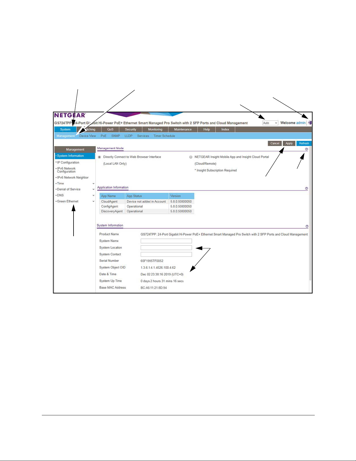
Navigation tabs, configuration menus, and page menu
The following figure shows the System Information page for model GS724TPP.
Navigation tabs Configuration menus
Logout button
Language menu
Help page
Buttons
Page menus
Configuration status and options
Figure 1. Switch navigation tabs, configuration menus, and page menu
The navigation tabs along the top of the web interface give you quick access to the various
switch functions. The tabs are always available and remain constant, regardless of which
feature you configure.
When you select a tab, the features for that tab appear as menus directly under
the tabs. The
configuration menus in the blue bar change according to the navigation tab that is selected.
The configuration pages for each feature are available as submenu links in the page menu on
the left side of the page. Some items in the menu expand to reveal multiple submenu links, as
the following figure shows.
Get Started User Manual16
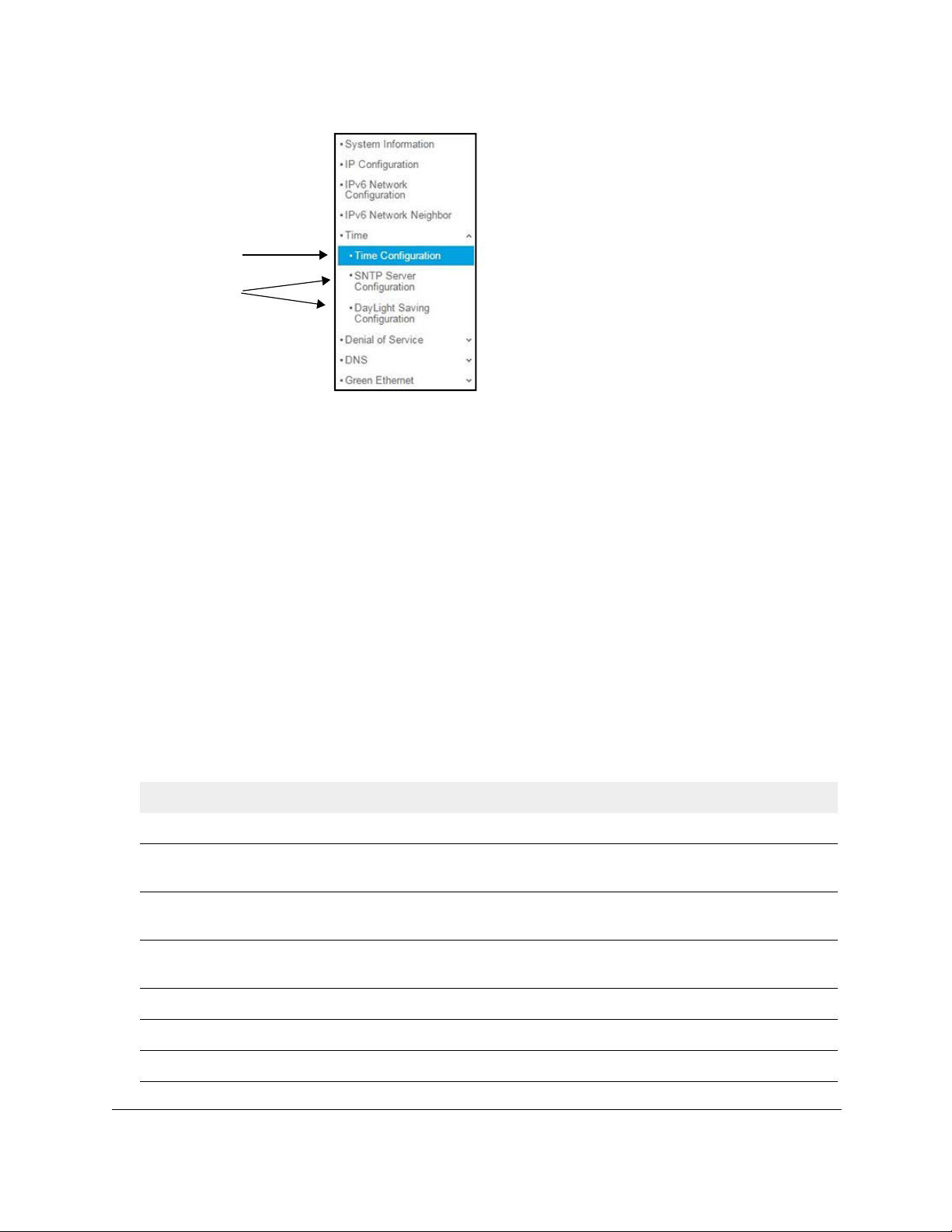
24-Port Gigabit (Hi-Power) PoE+ Ethernet Smart Managed Pro Switch with 2 SFP Ports
Link
Submenu
links
Figure 2. Switch page menu link and submenu links
Configuration and status options
The area directly under the configuration menus and to the right of the links displays the
configuration information or status for the page you select. On pages that contain
configuration options, you might be able to enter information into fields, select options from
menus, select check boxes, and select radio buttons.
Each page contains access to the HTML-based help that explains the fields and
configuration options for the page.
Buttons in the device UI
Each page also contains command buttons. The following table shows the command buttons
that are used throughout the pages in the device UI.
Table 1. Command buttons in the device UI
Button Function
Add Clicking the Add button adds the new item configured in the heading row of a table.
Apply Clicking the Apply button sends the updated configuration to the switch. Your sett
saved and configuration changes take effect immediately.
Cancel Clicking the Cancel button cancels the configuration on the page and resets the data on the
page to the previous values of the switch.
Clear Clicking the Clear button clears all the counters and resets the switch summary and detailed
statistics to default values.
Delete Clicking the Delete button removes the selected item.
Refresh Clicking the Refresh button refreshes the page with the latest information from the device.
ings are
Logout Clicking the Logout button ends the session.
Get Started User Manual17

24-Port Gigabit (Hi-Power) PoE+ Ethernet Smart Managed Pro Switch with 2 SFP Ports
User-defined fields
User-defined fields can contain 1 to 159 characters, unless otherwise noted on the
configuration web page. All characters can be used except for the ones stated in the following
table (unless specifically noted in a procedure for a feature).
Table 2. Invalid characters for user-defined fields
Invalid characters for user-defined fields
\ | / < > * ?
Context-sensitive help
When you log in to the switch, every page contains a link to the online help () that contains
information to assist in configuring and managing the switch. The online help pages are
context sensitive. For example, if the IP Configuration page is open, the help topic for that
page displays if you click the link to the online help.
About on-network and off-network access
You can access the switch either on-network or off-network:
• On-network and connected to the Internet. When you use the device UI, for easiest
access, we recommend that you cable the switch to a network that is connected to the
Internet and that includes a router or DHCP server that assigns IP addresses, power on
switch, and
the
to connect to the device UI. We refer to this setup as on-network or online.
For more information, see
on page 19).
• Off-network and not connected to the Internet. You can also configure the switch
connected directly only to the computer that you are using to c
switch is not connected to the network and the Internet. We refer to this setup as
off-network or offline. If your network does not include a DHCP server (or a router that
functions as a DHCP server), you must access the switch off-network.
For more information, see
Internet on page 27.
Note: We recommend that you register the switch to activate your warranty.
For more information, see Register the switch on page 30.
then use a computer that is connected to the same network as the switch
Access the switch on-network and connected to the Internet
onfigure it. That is, the
Access the switch off-network and not connected to the
Get Started User Manual18

24-Port Gigabit (Hi-Power) PoE+ Ethernet Smart Managed Pro Switch with 2 SFP Ports
Access the switch on-network and connected to the Internet
The DHCP client on the switch is enabled by default, allowing a DHCP server or router on the
network to assign an IP address to the switch.
If the switch is on-network, connected to a DHCP server, and connected to the Internet, you
can use a Windows-based computer to access the device UI of the switch and register the
switch with NETGEAR. For more information, see
access the switch on-network and connected to the Internet on page 20.
Use a Windows-based computer to
If you use a Mac, or if you do not know
tools to discover the IP address of the switch on the network:
• NETGEAR Insight app. Y
mobile device and discover the IP address of the switch. See
mobile app to discover the IP address of the switch on page 21.
• NETGEAR Switch Discovery Tool (NSDT): If you use a Mac or a Windows-based
computer, you can use the NSDT to discover the switch on your n
NETGEAR Switch Discovery Tool to discover the switch when it is connected to the
Internet on page 22.
• NETGEAR Smart Control Center (SCC): You can install the SCC on a Windows-based
computer. See
Control Center on page 24
• Other tools. You can also get the IP address of the switch from the DHCP server in the
network or use an IP scanner utility. See
address on page 25.
When you know the IP address, you can configure the switch in the following ways:
• Device UI. For configuration of all switch features, access the switch over the device UI.
See
Access the switch on-network and connected to the Internet when you know the
switch IP address on page 25.
• NETGEAR Smart Control Center (SCC): For
features, use the SCC on a Windows-based computer. By default, you can use the SCC
to discover the IP address of the switch, but you cannot use the SCC to perform any
actions on the switch. However, if you enable the configuration option of the SCC, you
can use it to configure the switch. See
Discover the switch in a network with a DHCP server using the Smart
ou can install the NETGEAR Insight app on an iOS or Android
the IP address of the switch, use one of the following
Use the NETGEAR Insight
etwork. See
Use other options to discover the switch IP
configuration of a limited number of switch
Manage the Smart Control Center on page 259.
Use the
For more information about the SCC, visit
• NETGEAR Insight app and Insight Cloud portal. Y
mode of the switch so that you can use the NETGEAR Insight app and Insight Cloud
portal to manage the switch remotely. For more information, see
management mode of the switch on page 35.
Get Started User Manual19
netgear.com/support/product/SCC.
ou can change the management
Change the

24-Port Gigabit (Hi-Power) PoE+ Ethernet Smart Managed Pro Switch with 2 SFP Ports
Use a Windows-based computer to access the switch on-network and connected to the Internet
For the following procedure, the network must provide Internet access.
To use a Windows-based computer to determine the switch IP address and access the
switch on-network and connected to the Internet:
1. Cable the switch to a network with a router or DHCP server that manages IP addresses.
2. Power on the switch.
The DHCP server assigns the switch an IP address.
3. Connect your
You can use a WiFi or wired network connection.
4. Open Windows Explorer.
5. Click the Network
6. If prompted, enable the Network Discovery feature.
7. Under Network Infrastructure, locate the switch model number.
8. Double-click GSmodel-XXXXXX, in
switch and XXXXXX represents the last six digits of the switch MAC address.
The page that displays depends on whether your browser is connected to the Internet,
whether the switch is connected to the Internet, and whether you activated the warranty.
9. Enter your credentials, which depend on the page that displays:
•
Register to activate your warranty page displays: If you did not yet activate your
warranty, the Register to activate your warranty page displays.
Register Your Device: To
-
button, and follow the directions onscreen to register the switch with your email
address and password. After you activate your warranty, you are no longer
prompted to register the switch.
If you do not have a NETGEAR account, you can create one.
computer to the same network as the switch.
link.
which GSmodel represents the model number of the
activate your warranty, click the Register Your Device
- Enter Registration Key: If you obtained a registration key, enter it. For more
information, see
registration key for offline access on page 31.
- Skip Registration & Access the UI: Y
activate your warranty, but if you do not activate your warranty within 30 days of
purchase, your warranty entitlement might be affected.
If you do not activate your warranty, the Register to activate your warranty page
continues to display when you log in.
• Device UI login page displays:
NETGEAR to activate your warranty, the Device UI login page displays. Enter one of
the following credentials:
Get Started User Manual20
Register the switch with your NETGEAR account and get a
If you previously registered the switch with
ou do not need to register the switch to

24-Port Gigabit (Hi-Power) PoE+ Ethernet Smart Managed Pro Switch with 2 SFP Ports
- Device admin password: Enter the device admin password. The default device
admin password is password. The first time that you enter the default device
admin password, the Change Default Password page displays, requiring you to
customize the device admin password for greater security.
- Insight network password: If you previously logged in to the device UI, you
changed the management mode to NETGEAR Insight, and you added the switch
to an Insight network location, enter the Insight network password to access the
device UI. (In such a situation, the Insight network password replaces the switch
device admin password.)
For information about the credentials, see
10. Click the Go
11. If the Change Default Password page displays, specify and confirm a new device admin
password,
The System Information page displays. You can now configure the switch.
button.
click the Submit button, and log in again with your new password.
Credentials for the device UI on page 28.
Use the NETGEAR Insight mobile app to discover the IP address of the switch
If the switch is connected to a WiFi router or access point, and the switch is connected to the
Internet, the NETGEAR Insight mobile app lets you discover the switch in your network.
If you do not use the NETGEAR Insight app to claim the switch by adding it to an Insight
network location, the switch is not registered and your warranty is not activated.
Using the NETGEAR Insight app to discover the IP address of the switch in your network is
not the same as managing the switch with the Insight app or the Insight Cloud Portal.
Note: The default management mode of the switch is the device UI. If you
want to use the Insight app or the Insight Cloud Portal to manage the
switch, you first must change the management mode (see
the management mode to NETGEAR Insight Mobile App and
Insight Cloud Portal on page 36). After you do so, you can manage
the switch with Insight and add the switch to an Insight network
location.
Change
Get Started User Manual21

24-Port Gigabit (Hi-Power) PoE+ Ethernet Smart Managed Pro Switch with 2 SFP Ports
To use the NETGEAR Insight app to discover the IP address of the switch in your
network when the switch is connected to the Internet:
1. On your mobile device, go to the app store, search for NETGEAR Insight, and download
the latest version of the app.
2. Connect your mobile device to the WiFi network of the WiFi router or access point to which
the switch is connected.
3. Open the NETGEAR Insight mobile app.
4. If you did not set up a NETGEAR account, tap Create
onscreen instructions.
5. Enter the email address and password for your account and tap LOG IN.
NETGEAR
Account and follow the
After you log in to your account, the IP address of the switch
6. Write down the switch IP address.
You can use this IP address to access the switch directly from
information about how to access the device UI of the switch, see
on-network and connected to the Internet when you know the switch IP address on
page 25.
displays in the device list.
a web browser. For
Access the switch
Use the NETGEAR Switch Discovery Tool to discover the switch when it is connected to the Internet
For easiest access, we recommend that you cable the switch to a network with a router or
DHCP server that assigns IP addresses, power on the switch, and then use a computer that
is connected to the same network as the switch.
The NETGEAR Switch Discovery Tool (NSDT) lets you discover the switch in your network
and access the device UI of the switch from a Mac or a Windows-based computer.
To install the NETGEAR Switch Discovery T
switch in your network when the switch is connected to the Internet:
1. Download the Switch
netgear.com/support/product/netgear-switch-discovery-tool.aspx.
Discovery Tool by visiting
ool and discover the IP address of the
Depending on the computer that you are using, download either the Mac version or the
version for a Windows-based computer.
2. Temporarily disable the firewall, Internet security, antivirus programs, or all of these on the
computer that
Get Started User Manual22
you use to configure the switch.

24-Port Gigabit (Hi-Power) PoE+ Ethernet Smart Managed Pro Switch with 2 SFP Ports
3. Unzip the NSDT files, and click or double-click the .exe file (for example,
NSDT-1.2.102.exe) to install the program on your computer.
You might see the tool icon appear on your Mac dock or Windows desktop.
4. Reenable the
security services on your computer.
5. Power on the switch.
The DHCP server assigns the switch an IP address.
6. Connect your
computer to the same network as the switch.
You can use a WiFi or wired connection. The computer and the switch must be on the
same Layer 2 network.
7. Open the Switch Discovery Tool.
T
o open the program, double-click the NETGEAR Switch Discovery Tool icon on your
desktop.
The initial page displays a menu and a button.
8. From the Choose
9. Click the Start
a connection menu, menu, select the network for this switch.
Searching button.
The NSDT displays the IP addresses of the switches that it discovers.
10. To access the switch from the NSDT, do the following:
a. Click the ADMIN PAGE
button next to your switch.
The page that displays depends on whether you activated the warranty.
b. Enter your credentials, which depend on the page that displays:
•
Register to activate your warranty page displays: If you did not yet activate
your warranty,
- Register Your Device: To activate your warranty
the Register to activate your warranty page displays.
, click the Register Your
Device button, and follow the directions onscreen to register the switch with
your email address and password. After you activate your warranty, you are
no longer prompted to register the switch.
If you do not have a NETGEAR account, you can create one.
- Enter Registration Key: If you obtained a registration key
information, see
Register the switch with your NETGEAR account and get a
registration key for offline access on page 31.
- Skip Registration & Access the UI: Y
ou do not need to register the switch to
activate your warranty, but if you do not activate your warranty within 30 days
of purchase, your warranty entitlement might be affected.
If you do not activate your warranty, the Register to activate your warranty
page continues to display when you log in.
, enter it. For more
Get Started User Manual23

24-Port Gigabit (Hi-Power) PoE+ Ethernet Smart Managed Pro Switch with 2 SFP Ports
• Device UI login page displays: If you previously registered the switch with
NETGEAR to activate your warranty, the Device UI login page displays. Enter one
of the following credentials:
- Device admin password:
device admin password is password. The first time that you enter the default
device admin password, the Change Default Password page displays,
requiring you to customize the device admin password.
- Insight network password: If you previously logged in to the device UI, you
changed the management mode to NETGEAR Insight, and you added the
switch to an Insight network location, enter the Insight network password to
access the device UI. (In such a situation, the Insight network password
replaces the switch device admin password.)
Enter the device admin password. The default
For information about the credentials, see
c. If you enter a password, click the Go
Submit button.
d. If the Change Default Password page displays, specify and confirm a new device
admin
The System Information page displays. You can now configure the switch.
password, click the Submit button, and log in again with your new password.
Credentials for the device UI on page 28.
button; If you enter a registration key, click the
Discover the switch in a network with a DHCP server using the Smart Control Center
This section describes how to set up your switch in a network that includes a DHCP server.
The DHCP client on the switch is enabled by default. When you connect the switch to your
network, the DHCP server automatically assigns an IP address to the switch. Use the Smart
Control Center (SCC) to discover the IP address automatically assigned to the switch.
For information about the SCC, visit
Note: By default, you can use the SCC to discover the IP address of the
switch, but you cannot use the SCC to perform any actions on the
switch. However, if you enable the configuration option of the SCC,
you can use it to configure the switch (see
Center on page 259).
https://www.netgear.com/support/product/SCC.
Manage the Smart Control
To install the switch in a network with a DHCP server:
1. Connect the
2. Power on the switch by connecting its power cord.
3. Install the SCC on your computer.
4. Start the SCC.
5. Click the Discover
Get Started User Manual24
switch to a network with a DHCP server.
button for the SCC to discover all the devices in the subnet.
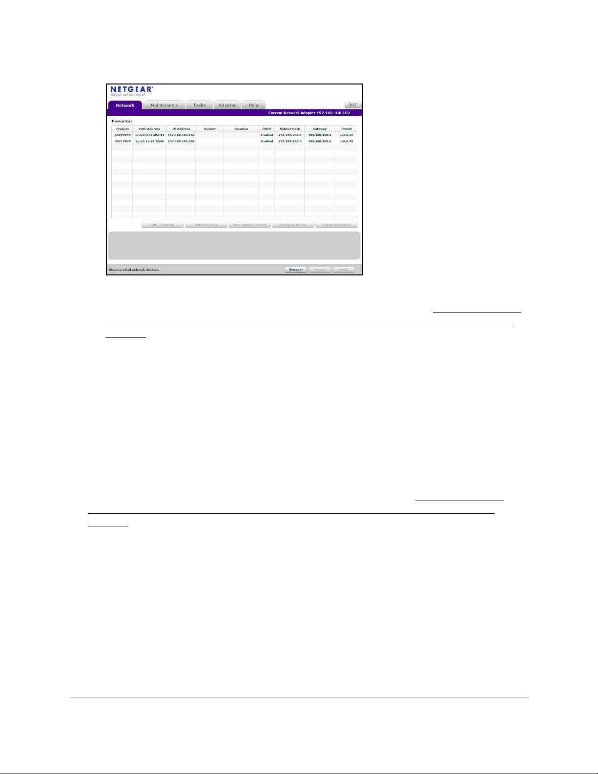
24-Port Gigabit (Hi-Power) PoE+ Ethernet Smart Managed Pro Switch with 2 SFP Ports
6. Write down the switch IP address assigned by the DHCP server.
For information about how to access the device UI of the switch, see
on-network and connected to the Internet when you know the switch IP address on
page 25.
Access the switch
Use other options to discover the switch IP address
If the switch is on-network, you can use one of the following options to determine the switch
IP address:
• Access the DHCP server. You can access the DHCP server (or router that functions as
a DHCP server) in your network and view the IP address that is assigned to the switch.
For more information, see the documentation for your DHCP server (or router).
• Use an IP scanner utility. IP scanner
An IP scanner utility lets you discover the IP address that is assigned to the switch.
For information about how to access the device UI of the switch, see Access the switch
on-network and connected to the Internet when you know the switch IP address on
page 25.
utilities are available free of charge on the Internet.
Access the switch on-network and connected to the Internet when you know the switch IP address
If the switch is on-network and you know the switch IP address, you can access the device
UI.
For the following procedure, the network must provide Internet access.
Get Started User Manual25

24-Port Gigabit (Hi-Power) PoE+ Ethernet Smart Managed Pro Switch with 2 SFP Ports
To access the switch on-network and connected to the Internet when you know the
switch IP address:
1. Launch a web browser.
2. In the address field of your web browser, enter the IP address of the switch.
The page that displays depends on whether your browser is conne
cted to the Internet,
whether the switch is connected to the Internet, and whether you activated the warranty.
3. Enter your credentials, which depend on the page that displays:
•
Register to activate your warranty page displays: If you did not yet activate your
warranty, the Register to activate your warranty page displays.
Register Your Device: To
-
activate your warranty, click the Register Your Device
button, and follow the directions onscreen to register the switch with your email
address and password. After you activate your warranty, you are no longer
prompted to register the switch.
If you do not have a NETGEAR account, you can create one.
- Enter Registration Key: If you obtained a registration key, enter it. For more
information, see
Register the switch with your NETGEAR account and get a
registration key for offline access on page 31.
- Skip Registration & Access the UI: Y
ou do not need to register the switch to
activate your warranty, but if you do not activate your warranty within 30 days of
purchase, your warranty entitlement might be affected.
If you do not activate your warranty, the Register to activate your warranty page
continues to display when you log in.
• Device UI login page displays:
If you previously registered the switch with
NETGEAR to activate your warranty, the Device UI login page displays. Enter one of
the following credentials:
- Device admin password:
Enter the device admin password. The default device
admin password is password. The first time that you enter the default device
admin password, the Change Default Password page displays, requiring you to
customize the device admin password for greater security.
- Insight network password: If you previously logged in to the device UI, you
management mode to NETGEAR Insight, and you added the switch to
changed
the
an Insight network location, enter the Insight network password to access the
device UI. (In such a situation, the Insight network password replaces the switch
device admin password.)
For information about the credentials, see
4. Click the Go
button.
Credentials for the device UI on page 28.
5. If the Change Default Password page displays, specify and confirm a new device admin
password,
click the Submit button, and log in again with your new password.
The System Information page displays. You can now configure the switch.
The System Information page displays. You can now configure the switch.
Get Started User Manual26

24-Port Gigabit (Hi-Power) PoE+ Ethernet Smart Managed Pro Switch with 2 SFP Ports
Access the switch off-network and not connected to the Internet
The default IP address of the switch is 192.168.0.239. The IP address of the computer that
you use to access the switch off-network must be in the same subnet as the default IP
address of the switch.
Note: If you prefer to use the Smart Control Center (SCC) to configure the
switch, you must access the switch off-network as described in the
following procedure and then enable the configuration option of the
SCC (see Manage the Smart Control Center on page 259).
To access the switch off-network and not connected to the Internet:
1. Change the
the switch.
If the DHCP client of the switch is enabled and you remove the switch from the network
with the DHCP server, the IP address reverts to the default IP
with a subnet of 255.255.255.0. If you already disabled the DHCP client and assigned a
static IP address to the switch, change the IP settings of your computer to be in the same
subnet as the static IP address.
For more information about changing the IP settings on your computer
following knowledge base articles at the NETGEAR website:
•
Windows-based computer. See the following article:
https://kb.netgear.com/27476/How-to-set-a-static-IP-address-in-Windows
• Mac. See the following article:
https://kb.netgear.com/000037250/Setting-a-static-IP-address-on-your-network-a
dapter-in-Mac-OS-for-direct-access-to-an-access-point
(The Mac article is written for an access point but is also valid for a switch.)
2. Connect your
3. Power on the switch by connecting its power cord.
4. Launch a
5. Open a web browser, and enter http://192.168.0.239.
IP settings of your computer to be in the same subnet as the IP settings of
address of 192.168.0.239
, see one of the
computer to the switch using an Ethernet cable.
web browser.
This is the default IP address of the switch. If you already di
assigned a static IP address to the switch, enter the static IP address of the switch.
The Enter Registration Key page displays.
6. Do
Get Started User Manual27
one of the following:
Enter a registration key. If you obtained a registration key, do the following:
•
a. Type or paste the key.
sabled the DHCP client and

24-Port Gigabit (Hi-Power) PoE+ Ethernet Smart Managed Pro Switch with 2 SFP Ports
For more information, see Register the switch with your NETGEAR account and
get a registration key for offline access on page 31.
b. Click the Submit button.
• Do not register at this time and access the device UI: Do the following:
a. Click
b. Enter one of the following credentials:
7. If the Change Default Password page displays, specify and confirm a new device admin
password, click the Submit button, and log in again with your new password.
The System Information page displays. You can now configure the switch.
8. After you complete the configuration of the switch, reconfigure the computer that you used
for
this process to its original TCP/IP settings.
the Skip
The Device UI login page displays.
-
Device admin password:
device admin password is password. The first time that you enter the default
device admin password, the Change Default Password page displays,
requiring you to customize the device admin password.
- Insight network password: If you previously logged in to the device UI, you
changed the management mode to NETGEAR Insight, and you added the
switch to an Insight network location, enter the Insight network password to
access the device UI. (In such a situation, the Insight network password
replaces the switch device admin password.)
For information about the credentials, see Credentials for the device UI on
page 28.
Registration & Access the UI button.
Enter the device admin password. The default
You can now connect your switch to your network using an Ethernet cable.
Credentials for the device UI
The information in this section applies to accessing the switch device UI in either
management mode. That is, it does not apply to accessing the NETGEAR Insight app and
Cloud portal.
To access the device UI, and depending on your situation, use one of the following
credentials:
• NETGEAR account credentials
You can register the switch online to activate your warranty by entering your NETGEAR
account credentials (see
the switch online on page 30). If you do not have a NETGEAR account, you can create
one.
Get Started User Manual28
Register the switch with your NETGEAR account and access
:

24-Port Gigabit (Hi-Power) PoE+ Ethernet Smart Managed Pro Switch with 2 SFP Ports
Alternatively, you can obtain a registration key and enter the key when the switch is offline
so that you are no longer prompted to activate your warranty (see
Register the switch
with your NETGEAR account and get a registration key for offline access on page 31).
• Device admin password:
You can access the device UI with your device admin password.
The first time that you access the device UI, enter the default device admin password
(password),
after which
you are required to customize the password for greater security.
Subsequent times that you log in to the device UI, use your customized device admin
password.
• NETGEAR Insight network location password:
NETGEAR Insight can affect how you access the switch device UI. After you add the
switch to
an Insight network location and change the management mode of the switch so
that you can use the NETGEAR Insight app and Insight Cloud portal to manage the
switch remotely (see
Change the management mode of the switch on page 35), the
Insight network location password replaces the switch device admin password. To
access the device UI, you must enter the Insight network locati
on password.
Even if you temporarily change the management mode of the switch back to Direct
Connect Web Browser Interface, for example to change settings that are not
Insight-manageable or for debugging purposes, you must enter the Insight network
location password.
For information about how the Insight network password functions, visit
netgear.com/support/product/Insight.aspx. For knowledge base articles about
NETGEAR Insight, visit
netgear.com/support.
The following table lists the essential credential options for access to the device UI.
Table 3. Credentials for access to the device UI
Management mode in the
device UI
Default mode:
Direct Connect Web Browser
Interface (Local LAN Only)
NETGEAR Insight Mobile App
and Insight Cloud Portal
(Cloud/Remote)
1. This situation occurs if you temporarily change the management mode of the switch from NETGEAR Insight Mobile App and
Insight Cloud Portal back to Direct Connect Web Browser Interface.
Added to an
Insight network
No Device admin password
1
Yes
No Device admin password Limited device UI menu.
Yes Insight network password Limited device UI menu.
Credentials Device UI menu
Full device UI menu
Insight network password
Not managed through
NETGEAR Insight.
Managed through
NETGEAR Insight.
Get Started User Manual29

24-Port Gigabit (Hi-Power) PoE+ Ethernet Smart Managed Pro Switch with 2 SFP Ports
Register the switch
You can register the switch online or offline to activate your warranty, after which you are no
longer prompted to activate your warranty when you log in:
• Online registration for on-network access: If your switch is on-network or connected to
the Internet, you can register the switch with your NETGEAR account credentials and
activate your warranty. During the registration process, the switch contacts a NETGEAR
server. For more information, see
access the switch online on page 30.
• Registration for off-network access: Y
is connected to the Internet and get a registration key. If the switch is off-network or not
connected to the Internet, you can enter the registration key. After you do so, the Register
to activate your warranty page no longer displays when you log in. For more information,
Register the switch with your NETGEAR account and get a registration key for
see
offline access on page 31.
Register the switch with your NETGEAR account and
ou can register your switch from any device that
Register the switch with your NETGEAR account and access the switch online
For initial registration and access with your NETGEAR account, the switch must be
connected to the Internet so that it can communicate with a NETGEAR server.
If you do not own a free NETGEAR account, you can create one during the registration
process.
To register and access the switch online over the device UI with your NETGEAR
account:
1. Connect your
You can use a WiFi or wired connection to connect your computer to the network, or
connect directly to a switch that is off-network using an Ether
2. Launch a web browser.
3. In the address field of your web browser, enter the IP address of the switch.
For information about finding the IP address of the switch, see
on-network and connected to the Internet on page 19 or Access the switch off-network
and not connected to the Internet on page 27.
The Register to activate your warranty page displays.
computer to the same network as the switch.
net cable.
Access the switch
4. Click the Register
switch with your email address and password and activate the warranty.
You are only prompted to do this once to confirm registration of your switch.
Get Started User Manual30
Your Device button and follow the directions onscreen to register the

24-Port Gigabit (Hi-Power) PoE+ Ethernet Smart Managed Pro Switch with 2 SFP Ports
If you did not yet create a NETGEAR account, click the Create account link, follow the
directions onscreen to create an account, and register the switch with your email address
and password.
For information about the credentials, see
5. If the Change Default Password page displays, specify and confirm a new device admin
password,
The System Information page displays. You can now configure the switch.
click the Submit button, and log in again with your new password.
Credentials for the device UI on page 28.
Register the switch with your NETGEAR account and get a registration key for offline access
Note: If you register your switch with your NETGEAR account and then
access the switch connected to the Internet, you do not need a
registration key because the Device UI login page displays. That is,
you are no longer prompted to activate your warranty.
After you register your switch with your NETGEAR account, you can get a registration key,
access
to the device UI, enter the registration key. After you enter the registration key, you are no
longer prompted to activate your warranty. Instead, the Device UI login page displays.
You can visit
serial number, and get a registration key.
the switch offline or not connected to the Internet, and either before or after you log in
mynetgear.com, log in to your NETGEAR account, register the switch using its
You can also use the NETGEAR Insight app to get a registration key. NETGEAR Insight
Premium or Pro subscribers can use the Insight Cloud Portal to get a registration key. For
information about how the registration key functions with Insight, visit
netgear.com/support/product/Insight.aspx. For knowledge base articles about NETGEAR
Insight, visit
To register the switch with your NETGEAR account and get a registration key:
1. From a computer or mobile device that is connected to the Internet, go to
mynetgear.com.
2. Log in to your NETGEAR account.
If you do not have a free NETGEAR account, you can create one.
3. From the menu on the left, select Register
The page adjusts.
4. In the Serial
The serial number consists of 13 digits. The serial number is usually printed
the bottom or the back panel of the switch.
5. Click the Register button.
Get Started User Manual31
netgear.com/support.
a Product.
Number field, enter the serial number of the switch.
on a label on

24-Port Gigabit (Hi-Power) PoE+ Ethernet Smart Managed Pro Switch with 2 SFP Ports
The switch is registered with NETGEAR.
6. If the My Products page does not display, select My
The page adjusts.
7. Select the radio button for the newly registered switch, and click the Get
button.
The registration key is displayed, and an email with the registration key is sent to your
NETGEAR account email address.
Products from the menu.
Registration Key
Access the switch offline with a registration key
After you get a registration key, you can access the switch offline and enter the registration
key. For more information, see one of the following sections:
• Access the switch offline and enter the registration key before you log in on page 32
• Access the switch offline and enter the registration key after you log in on page 33
After you enter the registration key, you are no longer prompted to activate your warranty
when you log in. Instead, the Device UI login page displays.
Access the switch offline and enter the registration key before you log in
If you obtain a registration key, you can access the switch offline and enter the key before you
log in to the device UI.
To access the switch offline and enter the registration key before you log in to the
device UI:
1. Change the
the switch.
If the DHCP client of the switch is enabled and you remove the switch from the network
with the DHCP server, the IP address reverts to the default IP
with a subnet of 255.255.255.0. If you already disabled the DHCP client and assigned a
static IP address to the switch, change the IP settings of your computer to be in the same
subnet as the static IP address.
For more information about changing the IP settings on your computer
following knowledge base articles at the NETGEAR website:
•
Windows-based computer: See the following article:
https://kb.netgear.com/27476/How-to-set-a-static-IP-address-in-Windows
• Mac: See the following article:
https://kb.netgear.com/000037250/Setting-a-static-IP-address-on-your-network-a
dapter-in-Mac-OS-for-direct-access-to-an-access-point
(The Mac article is written for an access point but is also valid for a switch.)
2. Connect your
3. Power on the switch by connecting its power cord.
IP settings of your computer to be in the same subnet as the IP settings of
address of 192.168.0.239
, see one of the
computer to the switch using an Ethernet cable.
Get Started User Manual32

24-Port Gigabit (Hi-Power) PoE+ Ethernet Smart Managed Pro Switch with 2 SFP Ports
4. Launch a web browser.
5. Open a web browser, and enter http://192.168.0.239.
This is the default IP address of the switch. If you already di
assigned a static IP address to the switch, enter the static IP address of the switch.
The Enter Registration Key page displays.
6. Enter
7. Click the Submit
8. Enter one of the following credentials:
9. Click the Go
10. If the Change Default Password page displays, specify and confirm a new device admin
the registration key.
button.
The registration takes effect on the switch and you are no longer prompted to activate
your warranty when you log in.
The Device UI login page displays.
•
Device admin password:
admin password is password. The first time that you enter the default device admin
password, the Change Default Password page displays, requiring you to customize
the device admin password.
• Insight network password: If
the management mode to NETGEAR Insight, and you added the switch to an Insight
network location, enter the Insight network password to access the device UI. (In such
a situation, the Insight network password replaces the switch device admin
password.)
button.
password,
click the Submit button, and log in again with your new password.
Enter the device admin password. The default device
you previously logged in to the device UI, you changed
sabled the DHCP client and
The System Information page displays. You can now configure the switch.
11. After you complete the configuration of the switch, reconfigure the computer that you used
for
this process to its original TCP/IP settings.
You can now connect your switch to your network using an Ethernet cable.
Access the switch offline and enter the registration key after you log in
If you access the switch offline and obtain a registration key afterwards, you can enter the
key on a page in the device UI.
To access the switch offline and enter the registration key after you log in to the
device UI:
1. Connect your
You can use a WiFi or wired connection to connect your computer to the network, or
connect directly to a switch that is off-network using an Ether
2. Launch a web browser.
3. In the address field of your web browser, enter the IP address of the switch.
Get Started User Manual33
computer to the same network as the switch.
net cable.

24-Port Gigabit (Hi-Power) PoE+ Ethernet Smart Managed Pro Switch with 2 SFP Ports
If you do not know the IP address of the switch, see Access the switch on-network and
connected to the Internet on page 19 or Access the switch off-network and not
connected to the Internet on page 27.
The Register to activate your warranty page displays.
4. Click the Skip
The Device UI login page displays.
5. Enter one of the following credentials:
•
Device admin password:
admin password is password. The first time that you enter the default device admin
password, the Change Default Password page displays, requiring you to customize
the device admin password.
• Insight network password: If
the management mode to NETGEAR Insight, and you added the switch to an Insight
network location, enter the Insight network password to access the device UI. (In such
a situation, the Insight network password replaces the switch device admin
password.)
6. Click the Go
7. If the Change Default Password page displays, specify and confirm a new device admin
password,
The System Information page displays. You can now configure the switch.
8. Select Maintenance >
The Registration Key page displays.
Registration & Access the UI button.
Enter the device admin password. The default device
you previously logged in to the device UI, you changed
button.
click the Submit button, and log in again with your new password.
Registration Key.
9. In the field, type or paste the registration key.
10. Click the Submit
The registration takes effect on the switch and you are no longer prompted to activate
your warranty when you log in.
button.
Change the language of the device UI
By default, the language is set to Auto. You can set the language to a specific one.
To change the language of the device UI:
1. Connect your
You can use a WiFi or wired connection to connect your computer to the network, or
connect directly to a switch that is off-network using an Ether
2. Launch a web browser.
3. In the address field of your web browser, enter the IP address of the switch.
Get Started User Manual34
computer to the same network as the switch.
net cable.

24-Port Gigabit (Hi-Power) PoE+ Ethernet Smart Managed Pro Switch with 2 SFP Ports
If you do not know the IP address of the switch, see Access the switch on-network and
connected to the Internet on page 19 or Access the switch off-network and not
connected to the Internet on page 27.
The Device UI login page displays.
If you did not yet activate your warranty, the Register to activate your warranty page
displays. For more information, see
4. Enter one of the following passwords:
• Enter your device admin password.
• If you previously managed the switch through the Insight app or
the Insight network password for the last Insight network location.
Register the switch on page 30.
Cloud portal, enter
For information about the credentials, see
5. Click the Go
The System Information page displays.
6. At the top of the page, to the left of W
A confirmation pop-up window displays.
7. Click the OK
You are logged out. The language of the device UI is set to the language that you
selected.
8. To continue configuring the switch, log in again.
button.
button.
Credentials for the device UI on page 28.
elcome, select a language from the language menu.
Change the management mode of the switch
By default, the management mode on the switch is Directly Connect to Web Browser
Interface (which is the same as the device UI). You can also change the management mode
to NETGEAR Insight Mobile App and Insight Cloud Portal.
About changing the management mode
The following applies to changing the management mode:
• Changing to the NETGEAR Insight Mobile App and Insight Cloud Portal mode.
- The first time that you enable this mode, the switch is reset to its factory default
settings so that you can create the switch configuration and network topology using
the Insight app or the Insight Cloud portal.
- If you previously added the switch to a network location on the Insight app or Insight
Cloud portal, all Insight-manageable device settings are returned to the last
Get Started User Manual35

24-Port Gigabit (Hi-Power) PoE+ Ethernet Smart Managed Pro Switch with 2 SFP Ports
configuration saved on the cloud server, including the switch device admin password
(that is, the password is reset to the Insight network location password).
- If you use the Insight app or the Insight Cloud portal, you can temporarily change the
management mode of the switch back to Directly Connect to Web B
You can then access the device UI for settings that are not Insight-manageable, for
complex tasks such as integrating with an existing network of devices that are not
managed through Insight, and for debugging purposes. When you are done, you can
change the management mode back to NETGEAR Insight Mobile App and Insight
Cloud Portal.
• Changing back to Directly Connect to W
After you change the management mode, back up your configuration. Then, reset the
switch to factory defaults. Finally
more information, see
Web Browser Interface on page 37.
After you change the management mode, the follow occurs:
Change the management mode back to Directly Connect to
, restore your configuration and reboot the switch. For
eb Browser Interface mode
rowser Interface.
.
- The NETGEAR Insight Mobile App and Insight Cloud Portal managem
disabled and the current Insight-manageable device settings are saved to the cloud
server.
- Any changes that you make using the Directly Connect to Web Bro
management mode are not saved to the cloud server.
- All configuration menus and options are available in the device UI.
ent mode is
wser Interface
Change the management mode to NETGEAR Insight Mobile App and Insight Cloud Portal
To change the management mode of the switch to NETGEAR Insight Mobile App and
Insight Cloud portal:
1. Connect your computer to the same network as the switch.
You can use a WiFi or wired connection to connect your computer to the network, or
connect directly to a switch that is off-network using an Ether
2. Launch a web browser.
3. In the address field of your web browser, enter the IP address of the switch.
If you do not know the IP address of the switch, see
connected to the Internet on page 19 or Access the switch off-network and not
connected to the Internet on page 27.
Access the switch on-network and
net cable.
The Device UI login page displays.
If you did not yet activate your warranty, the Register to activate your warranty page
displays. For more information, see
4. Enter one of the following passwords:
• Enter your device admin password.
Get Started User Manual36
Register the switch on page 30.

24-Port Gigabit (Hi-Power) PoE+ Ethernet Smart Managed Pro Switch with 2 SFP Ports
• If you previously managed the switch through the Insight app or Cloud portal, enter
the Insight network password for the last Insight network location.
For information about the credentials, see Credentials for the device UI on page 28.
5. Click the Go
The System Information page displays.
6. Select the NETGEAR
An Alert pop-up window displays.
7. Read the text, and click the OK
The pop-up window closes.
8. Click the Apply
Another pop-up window displays.
9. Click the OK
The pop-up window closes, the System Information page closes, and your settings are
saved.
The following occurs:
• The first time that you enable this mode, the switch is reset to its factory default
settings.
• The switch connects to the cloud server
• If you previously added the switch to a network on the Insight
portal, all Insight-manageable device settings are returned to the last configuration
saved on the cloud server, including the device admin password (that is, the
password is reset to the Insight network password).
• The Device UI login page might display again. (Y
button.
button.
button.
Insight Mobile App and Insight Cloud Portal radio button.
button.
.
app or Insight Cloud
ou can close th
e page.)
You can now manage the switch using the Insight mobile app or Insight Cloud portal.
For more information about NETGEAR Insight, visit
netgear.com/support/product/Insight.aspx. For knowledge base articles about NETGEAR
Insight, visit
netgear.com/support.
netgear.com/insight and
Change the management mode back to Directly Connect to Web Browser Interface
To change the management mode of the switch back to Directly Connect to Web
Browser Interface:
1. Connect your computer to the same network as the switch.
You can use a WiFi or wired connection to connect your computer to the network, or
connect directly to a switch that is off-network using an Ether
Get Started User Manual37
net cable.

24-Port Gigabit (Hi-Power) PoE+ Ethernet Smart Managed Pro Switch with 2 SFP Ports
2. Launch a web browser.
3. In the address field of your web browser, enter the IP address of the switch.
If you do not know the IP address of the switch, see
Access the switch on-network and
connected to the Internet on page 19 or Access the switch off-network and not
connected to the Internet on page 27.
The Device UI login page displays.
If you did not yet activate your warranty, the Register to activate your warranty page
displays. For more information, see
Register the switch on page 30.
4. Enter one of the following passwords:
• Enter your device admin password.
• If you previously managed the switch through the Insight app or
Cloud portal, enter
the Insight network password for the last Insight network location.
For information about the credentials, see
5. Click the Go
button.
Credentials for the device UI on page 28.
The System Information page displays.
6. Select the Directly
Connect to Web Browser Interface radio button.
An Alert pop-up window displays.
7. Read the text, and click the OK
button.
The pop-up window closes.
8. Click the Apply
button.
Another pop-up window displays.
9. Click the OK
button.
The pop-up window closes, the System Information page closes, and your settings are
saved. Any current Insight-manageable device settings are saved
to the cloud server.
The Device UI login page displays.
10. Log in again.
The System Information page displays.
Note: The following step uses an HTTP session to back up the configur
For information about using a TFTP session, see
Use TFTP to export a
ation.
file from the switch to a TFTP server on page 380.
11. Back up the configuration:
a. Select
Maintenance > Export > HTTP File Export.
The HTTP File Export page displays.
b. From
the File
c. Click the Apply
Type menu, select Text Configuration.
button.
Get Started User Manual38

24-Port Gigabit (Hi-Power) PoE+ Ethernet Smart Managed Pro Switch with 2 SFP Ports
A pop-up window displays.
d. Navigate to
a location on your computer and save the file.
The file transfer begins. The page displays information about the file transfer
progress.
12. Reset the switch to factory default settings:
a. Select
Maintenance > Reset > Factory Default.
The Default Settings page displays.
b. Select
the Reset
configuration to factory default (EXCEPT registered device
status), and clear device logs radio button.
This option resets the switch to its factory default settings but does not change its
registration status with NETGEAR.
c. Click the Apply
button.
An Alert pop-up window displays.
d. Click the OK
button.
All configuration settings are reset to their factory default values. The
the switch is enabled. Your device admin password is reset to the default password
(password). This process takes about 135 seconds.
The Device UI login page displays.
DHCP client on
In the unlikely situation that the Device UI page does not display and you cannot log
in, see
Access the switch on-network and connected to the Internet on page 19 or
Access the switch off-network and not connected to the Internet on page 27.
e. Enter the device admin password.
The default device admin password is
password. The first time that you enter the
default device admin password, the Change Default Password page
requiring you to customize the device admin password.
The System Information page displays.
Note: The following step uses an HTTP session to restore the configuration. For
information about using a TFTP session, see
Use TFTP to download a file
to the switch or update the software image on page 383.
13. Restore the
configuration that you saved in Step 11:
a. Select Maintenance > Update > HTTP Firmware/File Update.
The HTTP Firmware/File Update page displays.
b. From
the File
c. Click the Browse
Type menu, select Text Configuration.
button and locate and select configuration file that you saved in
Step 11.
d. Click the Apply
button.
displays,
Get Started User Manual39

24-Port Gigabit (Hi-Power) PoE+ Ethernet Smart Managed Pro Switch with 2 SFP Ports
The file transfer begins. The page displays information about the progress of the file
transfer. The switch applies the configuration automatically.
14. Reboot the switch:
a. Select Maintenance > Reset > Device Reboot.
The Device Reboot page displays.
b. Select
c. Click the Apply
An Alert pop-up window displays.
d. Click the OK
The switch reboots.
The Device UI login page displays.
15. Log
in again.
The System Information page displays.
options in the device UI.
the check box.
button.
button to confirm.
You can now configure the switch using all
Use the Device View of the device UI
The Device View displays the ports on the switch. This graphic tool provides an alternate way
to navigate to configuration and monitoring options. The graphic tool also provides
information about device ports, configuration and status, tables, and feature components.
To use the Device View:
1. Connect your
You can use a WiFi or wired connection to connect your computer to the network, or
connect directly to a switch that is off-network using an Ether
2. Launch a web browser.
3. In the address field of your web browser, enter the IP address of the switch.
If you do not know the IP address of the switch, see
connected to the Internet on page 19 or Access the switch off-network and not
connected to the Internet on page 27.
The Device UI login page displays.
If you did not yet activate your warranty, the Register to activate your warranty page
displays. For more information, see
Get Started User Manual40
computer to the same network as the switch.
net cable.
Access the switch on-network and
Register the switch on page 30.

24-Port Gigabit (Hi-Power) PoE+ Ethernet Smart Managed Pro Switch with 2 SFP Ports
4. Enter one of the following passwords:
• Enter your device admin password.
• If you previously managed the switch through the Insight app or Cloud portal, enter
the Insight network password for the last Insight network location.
For information about the credentials, see
5. Click the Go
button.
Credentials for the device UI on page 28.
The System Information page displays.
6. Select System > Device
View.
The following table describes the system LEDs in the Device View.
System LED Color Description
Power LED Solid green Power is supplied to the switch and the switch is operating normally.
Note: The physical Power LED on the switch can also light solid amber.
Solid amber does not apply to the Device View. (If the switch is off or
booting, you cannot access the Device View.)
Fan LED Off The internal fan is operating normally
Solid yellow The internal fan failed.
Note: In this situation, the physical Fan LED on the switch lights solid
amber rather than yellow.
PoE Max LED Of
f Sufficient (more than 7W of) PoE power is available on the switch
Solid yellow Less than 7W of PoE power is available on the switch.
Note: In this situation, the physical PoE Max LED on the switch lights
solid amber rather than yellow.
Note: The physical PoE Max LED on the switch can also blink amber,
indicating that at least once during the previous two minutes, less than
7W of PoE power was available.
For each Ethernet port and for the two SFP fiber ports in the Device view, colors indicate
the link status of the port. In addition, each Ethernet port also provides two port LEDs,
which are located on the left. For each port, an upper port LED indicates the port speed
status and a lower port LED indicates the port PoE status.
Get Started User Manual41

24-Port Gigabit (Hi-Power) PoE+ Ethernet Smart Managed Pro Switch with 2 SFP Ports
The following table describes the ports and port LEDs in the Device View.
Port or
port LED
Ethernet port Black No Ethernet link is established.
Upper Ethernet
port LED
Lower Ethernet
port LED
Color Description
Solid green An Ethernet link is established.
Solid red An error occurred on the port or the port is administratively disabled.
Solid dark green No Ethernet link is established.
Solid green A 1000 Mbps Ethernet link is established
Blinking green The port is transmitting or receiving packets at 1000 Mbps.
Solid yellow A 10 Mbps or 100 Mbps Ethernet link is established.
Note: In this situation, the physical upper port LED on the switch lights
solid amber rather than yellow.
Blinking yellow The port is transmitting or receiving packets at 10 Mbps or 100 Mbps.
Note: In this situation, the physical upper port LED on the switch blinks
amber rather than yellow.
Solid dark green The port is not delivering PoE.
Solid green The port is delivering PoE.
Solid yellow A PoE fault occurred.
Note: In this situation, the physical lower port LED on the switch lights
solid amber rather than yellow.
SPF fiber port Black No SFP module link is established.
Solid green A 1000 Mbps link is established.
Blinking green The SFP fiber port is transmitting or receiving packets at 1000
Mbps.
7. Click a port to open a menu that displays statistics and configuration options.
You can select a menu option to access the page that contains the configuration or
monitoring options.
If you right-click the graphic, but do not right-click a specific port, the
main menu displays.
This menu contains the same options as the navigation tabs at the top of the page.
Get Started User Manual42

24-Port Gigabit (Hi-Power) PoE+ Ethernet Smart Managed Pro Switch with 2 SFP Ports
Right-click the specific port that you want to view or configure to see a menu that displays
statistics and configuration options. Select the menu option to access the page that
contains the configuration or monitoring options.
Get Started User Manual43

24-Port Gigabit (Hi-Power) PoE+ Ethernet Smart Managed Pro Switch with 2 SFP Ports
Configure interface settings
The switch supports physical and logical interfaces. Interfaces are identified by their type and
the interface number. The physical ports are Gigabit interfaces and are numbered on the
front panel. You configure the logical interfaces by using the software.
The following table describes the naming convention for all interfaces available on
Table 4. Naming conventions for interfaces
Interface Description Example
Physical The physical ports are 1 Gigabit Ethernet interfaces and are
numbered sequentially starting from 1.
Link aggregation group (LAG) LAG interfaces are logical interfaces that are used only for
bridging functions.
CPU management interface This is the internal switch interface responsible for the switch
base
MAC address.
always listed in the MAC Address Table.
This interface is not configurable and is
the switch.
g1, g2, g12
l1, l2, l3
c1
For some features that allow you to configure interface settings, you can apply the same
settings simultaneously to any of the following:
• A single port
• Multiple ports
• All ports
• A single LAG
• Multiple LAGs
• All LAGs
• Multiple ports and LAGs
• All ports and LAGs
Many of the pages that allow you to configure or view interface settings include links to
display all ports, all LAGs, or all ports and LAGs on the page.
Use these links as follows:
• To display all ports, click the 1 link.
• To display all LAGs, click the LAG link.
• To display all ports and LAGs, click the All
The procedures in this section describe how to select the ports
link.
and LAGs to configure. The
procedures assume that you are already logged in to the switch. If you do not know how to
Get Started User Manual44

24-Port Gigabit (Hi-Power) PoE+ Ethernet Smart Managed Pro Switch with 2 SFP Ports
log in to the switch, see Access the switch on-network and connected to the Internet on
page 19 or Access the switch off-network and not connected to the Internet on page 27.
To configure a single port by using the Go To Interface field:
1. Ensure that the
2. In the Go T
For more information, see
3. Click the Go
page is displaying all ports, and not only the LAGs.
o Interface field, type the port number, for example g3.
Configure interface settings on page 44.
button.
The check box associated with the interface is selected, the row for the
is highlighted, and the interface number appears in the heading row.
4. Configure the desired settings.
5. Click the Apply
button.
selected interface
Your settings are saved.
To configure a single LAG by using the Go To Interface field:
1. Click the LAG
2. In the Go T
For information, see
3. Click the Go
link or the All link to display the LAGs.
o Interface field, type the LAG number, for example l3.
Configure interface settings on page 44.
button.
The check box associated with the interface is selected, the row for the
is highlighted, and the interface number appears in the heading row.
4. Configure the desired settings.
5. Click the Apply
button.
Your settings are saved.
To configure a single port:
1. Ensure that the
page is displaying all ports, and not only the LAGs.
2. Select the check box next to the port number.
Get Started User Manual45
selected interface

24-Port Gigabit (Hi-Power) PoE+ Ethernet Smart Managed Pro Switch with 2 SFP Ports
The row for the selected interface is highlighted, and the interface number appears in the
heading row.
3. Configure the desired settings.
4. Click the Apply
button.
Your settings are saved.
To configure a single LAG:
1. Click the LAG
link or the All link to display the LAGs.
2. Select the check box next to the LAG number.
The row
for the selected interface is highlighted, and the interface number appears
heading row.
3. Configure the desired settings.
4. Click the Apply
button.
Your settings are saved.
To configure multiple ports:
1. Ensure that the
page is displaying all ports, and not only the LAGs.
2. Select the check box next to each port to configure.
The row for each selected interface is highlighted.
in the
3. Configure the desired settings.
4. Click the Apply
button.
Your settings are saved.
To configure multiple LAGs:
1. Click the LAG
link or the All link to display the LAGs.
2. Select the check box next to each LAG to configure.
The check box associated with each interface is selected, and the row for each selected
interface is highlighted.
Get Started User Manual46

24-Port Gigabit (Hi-Power) PoE+ Ethernet Smart Managed Pro Switch with 2 SFP Ports
3. Configure the desired settings.
4. Click the Apply
button.
Your settings are saved.
To configure all ports:
1. Ensure that the
page is displaying only ports, and not LAGs.
2. Select the check box in the heading row.
The check box associated with every port is selected, and the rows for all ports are
highlighted.
3. Configure the desired settings.
4. Click the Apply
button.
Your settings are saved.
To configure all LAGs:
1. Click the LAG
link to display only the LAG interfaces.
2. Select the check box in the heading row.
The check box associated with every LAG is selected, and the rows for all LAGs are
highlighted.
3. Configure the desired
4. Click the Apply
settings.
button.
Your settings are saved.
To configure multiple ports and LAGs:
1. Click the All
link to display all ports and LAGs.
2. Select the check box associated with each port and LAG to configure.
Get Started User Manual47

24-Port Gigabit (Hi-Power) PoE+ Ethernet Smart Managed Pro Switch with 2 SFP Ports
The rows for the selected ports and LAGs are highlighted.
3. Configure the
4. Click the Apply
Your settings are saved.
To configure all ports and LAGs:
1. Click the All
2. Select the check box in the heading row.
The check box
and LAGs are highlighted.
3. Configure the desired settings.
4. Click the Apply
Your settings are saved.
desired settings.
button.
link to display all ports and LAGs.
associated with every port and LAG is selected,
button.
and the rows for all ports
Access the NETGEAR support website
From the device UI, you can access the NETGEAR support website at
netgear.com/support.
To access the support website from the device UI:
1. Connect your
You can use a WiFi or wired connection to connect your computer to the network, or
connect directly to a switch that is off-network using an Ether
2. Launch a web browser.
3. In the address field of your web browser, enter the IP address of the switch.
If you do not know the IP address of the switch, see
connected to the Internet on page 19 or Access the switch off-network and not
connected to the Internet on page 27.
The Device UI login page displays.
If you did not yet activate your warranty, the Register to activate your warranty page
displays. For more information, see
4. Enter one of the following passwords:
• Enter your device admin password.
• If you previously managed the switch through the Insight app or
the Insight network password for the last Insight network location.
For information about the credentials, see
computer to the same network as the switch.
net cable.
Access the switch on-network and
Register the switch on page 30.
Cloud portal, enter
Credentials for the device UI on page 28.
5. Click the Go
Get Started User Manual48
button.

24-Port Gigabit (Hi-Power) PoE+ Ethernet Smart Managed Pro Switch with 2 SFP Ports
The System Information page displays.
6. Select Help >
The Support page displays.
7. To access the NETGEAR support site for the switch, click the Apply
Support.
button.
Access the user manual online
The user manual (the guide you are now reading) is available at the NETGEAR download
center at
To access the user manual online from the device UI:
1. Connect your computer to the same network as the switch.
2. Launch a web browser.
3. In the address field of your web browser, enter the IP address of the switch.
netgear.com/support/download/.
You can use a WiFi or wired connection to connect your computer to the network, or
connect directly to a switch that is off-network using an Ether
If you do not know the IP address of the switch, see
connected to the Internet on page 19 or Access the switch off-network and not
connected to the Internet on page 27.
Access the switch on-network and
net cable.
The Device UI login page displays.
If you did not yet activate your warranty, the Register to activate your warranty page
displays. For more information, see
4. Enter one of the following passwords:
• Enter your device admin password.
• If you previously managed the switch through the Insight app or
the Insight network password for the last Insight network location.
For information about the credentials, see
5. Click the Go
The System Information page displays.
6. Select Help >
The User Guide page displays.
7. To access the NETGEAR download center, click the Apply
8. Enter the model number of the switch.
button.
Online Help > User Guide.
Register the switch on page 30.
Cloud portal, enter
Credentials for the device UI on page 28.
button.
Get Started User Manual49

2
2Configure System Information
This chapter contains the following sections:
•
View or define switch system information
• Configure the switch IP address settings
• Configure the IPv6 network interface
• Configure the time settings
• Configure Denial of Service settings
• Configure the DNS settings
• Configure Green Ethernet settings
• Use the Device View
• Configure Power over Ethernet
• Configure SNMP
• Configure LLDP
• Configure DHCP snooping
• Set up PoE timer schedules
50

24-Port Gigabit (Hi-Power) PoE+ Ethernet Smart Managed Pro Switch with 2 SFP Ports
View or define switch system information
You can view or define system information, view temperature information, view fan
information, and view software information.
View or define system information
When you log in, the System Information page displays. You can configure and view general
device information.
To view or define system information:
1. Connect your
You can use a WiFi or wired connection to connect your computer to the network, or
connect directly to a switch that is off-network using an Ether
2. Launch a web browser.
3. In the address field of your web browser, enter the IP address of the switch.
If you do not know the IP address of the switch, see
connected to the Internet on page 19 or Access the switch off-network and not
connected to the Internet on page 27.
The Device UI login page displays.
If you did not yet activate your warranty, the Register to activate your warranty page
displays. For more information, see
4. Enter one of the following passwords:
• Enter your device admin password.
• If you previously managed the switch through the Insight app or
the Insight network password for the last Insight network location.
For information about the credentials, see
5. Click the Go
computer to the same network as the switch.
net cable.
Access the switch on-network and
Register the switch on page 30.
Cloud portal, enter
Credentials for the device UI on page 28.
button.
The System Information page displays.
Configure System Information User Manual51

24-Port Gigabit (Hi-Power) PoE+ Ethernet Smart Managed Pro Switch with 2 SFP Ports
6. Define the following fields:
• System Name. Enter the name to identify this switch. You can use up to 255
alphanumeric characters. The default is blank.
• System Location. Enter the location of this switch. You can use up to 255
alphanumeric characters.
The default is blank.
• System Contact. Enter the contact person for this switch. You can use up to 255
alphanumeric characters.
7. Click the Apply
button.
The default is blank.
Your settings are saved.
The following table describes the status information that the System Information page
displays.
Field Description
Product Name The product name of this switch.
Serial Number The serial number of the switch.
System Object OID The base object ID for the switch's enterprise MIB.
Date & Time The current date and time.
Configure System Information User Manual52

24-Port Gigabit (Hi-Power) PoE+ Ethernet Smart Managed Pro Switch with 2 SFP Ports
Field Description
System Up Time The time in days, hours, and minutes since the last switch reboot.
Base Mac Address
Universally assigned hardware address of the switch.
View the fan status
The fans remove the heat generated by the power, CPU, and other components, and allow
the switch to function normally.
Model GS724TPv2 integrates two fans. Model GS724TPP integrates three fans. You can
view the fan status.
To view the fan status:
1. Connect your computer
You can use a WiFi or wired connection to connect your computer to the network, or
connect directly to a switch that is off-network using an Ethernet cable.
2. Launch
a web browser.
3. In the address field of your web browser, enter the IP address of the switch.
If you do not know the IP address of the switch, see
connected to the Internet on page 19 or Access the switch off-network and not
connected to the Internet on page 27.
The Device UI login page displays.
to the same network as the switch.
Access the switch on-network and
If you did not yet activate your warranty, the Register to activate your warranty page
displays. For more information, see
Register the switch on page 30.
4. Enter one of the following passwords:
• Enter your device admin password.
• If you previously managed the switch through the Insight app or Cloud portal, enter
the Insight network password for the last Insight network locat
For information about the credentials, see
5. Click the Go
button.
The System Information page displays.
6. Scroll down to the Fans section.
7. To refresh the page, click the Refresh button.
Configure System Information User Manual53
ion.
Credentials for the device UI on page 28.

24-Port Gigabit (Hi-Power) PoE+ Ethernet Smart Managed Pro Switch with 2 SFP Ports
The following table describes the nonconfigurable temperature and fan status information.
Table 5. Fan status
Field Description
FAN The fan index used to identify the fan for the switch.
Description The description of the fan temperature sensor.
Type Specifies whether the fan module is fixed or removable.
Speed The fan speed.
Duty level (%) The duty level of the fan.
State Specifies whether the fan is operational.
View the software versions
You can view the software versions that are running on the switch.
To view the software versions:
1. Connect your computer
to the same network as the switch.
You can use a WiFi or wired connection to connect your computer to the network, or
connect directly to a switch that is off-network using an Ethernet cable.
2. Launch
a web browser.
3. In the address field of your web browser, enter the IP address of the switch.
If you do not know the IP address of the switch, see
Access the switch on-network and
connected to the Internet on page 19 or Access the switch off-network and not
connected to the Internet on page 27.
The Device UI login page displays.
If you did not yet activate your warranty, the Register to activate your warranty page
displays. For more information, see
Register the switch on page 30.
4. Enter one of the following passwords:
• Enter your device admin password.
• If you previously managed the switch through the Insight app or Cloud portal, enter
the Insight network password for the last Insight network locat
For information about the credentials, see
Credentials for the device UI on page 28.
ion.
5. Click the Go
button.
The System Information page displays.
6. Scroll down to the Versions section.
Configure System Information User Manual54

24-Port Gigabit (Hi-Power) PoE+ Ethernet Smart Managed Pro Switch with 2 SFP Ports
7. To refresh the page, click the Refresh button.
The following table describes the nonconfigurable information displayed in the Versions
section of the System Information page.
Field Description
Model Name The model name of the switch.
Boot Version The version of the bootloader software of the switch.
Software Version The version number of the code currently running on the switch.
Configure the switch IP address settings
You can configure network information for the device UI, which is the logical interface used
for in-band connectivity with the switch through any of the switch’s front-panel ports. The
configuration parameters associated with the switch’s network interface do not affect the
configuration of the front panel ports through which traffic is switched or routed.
To configure the IP address and management VLAN information for the device UI:
1. Connect
You can use a WiFi or wired connection to connect your computer to the network, or
connect directly to a switch that is off-network using an Ethernet cable.
2. Launch
3. In the address field of your web browser, enter the IP address of the switch.
If you do not know the IP address of the switch, see
connected to the Internet on page 19 or Access the switch off-network and not
connected to the Internet on page 27.
The Device UI login page displays.
If you did not yet activate your warranty, the Register to activate your warranty page
displays. For more information, see
4. Enter one of the following passwords:
• After registration, enter the device admin password.
• If you previously managed the switch through the Insight app or Cloud portal, enter
your computer
a web browser.
the Insight network password for the last Insight network locat
to the same network as the switch.
Access the switch on-network and
Register the switch on page 30.
ion.
For information about the credentials, see
Configure System Information User Manual55
Credentials for the device UI on page 28.

24-Port Gigabit (Hi-Power) PoE+ Ethernet Smart Managed Pro Switch with 2 SFP Ports
5. Click the Go button.
The System Information page displays.
6. Select System > Management > IP Configuration.
The IP Configuration page displays.
7. Select
the
the appropriate radio button to specify how to configure the network information for
switch device UI:
• Static IP Address. Specifies that the IP address, subnet mask, and default gateway
must be manually configured. Enter this information in the fields below this radio
button.
• Dynamic IP Address (BOOTP).
Specifies
that the switch must obtain the IP address
through a BootP server.
• Dynamic IP Address (DHCP). Specifies that the switch must obtain the IP address
through a DHCP server.
8. If you selected the Static
This is the default setting.
IP Address radio button, configure the following network
information:
• IP Address.
The IP address of the network interface.
The default is 192.168.0.239.
Each part of the IP address must start with a number other than zero. For example, IP
addresses 001.100.192.6 and 192.001.10.3 are not valid.
• Subnet Mask. The IP subnet mask for the interface.
• Default Gateway. The default gateway for the IP interface.
The default is 255.255.255.0.
The default is
192.168.0.254.
9. Specify the
VLAN ID for the management VLAN.
The management VLAN is used to establish an IP connection to the switch from a
workstation that is connected to a port in the same VLAN. If not specified, the active
management VLAN ID is 1 (default), which allows an IP connection to be established
through any port.
When the management VLAN is set to a different value, an IP connection can be made
only through a port that is part of the management VLAN. Also,
of the port to be connected in that management VLAN must be the same as the
management VLAN ID.
Note: Make sure that the VLAN that must be the management VLAN exists.
Also make sure that the PVID of at least one port in the VLAN is the
same as the management VLAN ID. For information about creating
VLANs and configuring the PVID for a port, see
page 141.
The following requirements apply to the management VLAN:
• Only one management VLAN can be active at a time.
Configure System Information User Manual56
the port VLAN ID (PVID)
Configure VLANs on

24-Port Gigabit (Hi-Power) PoE+ Ethernet Smart Managed Pro Switch with 2 SFP Ports
• When a new management VLAN is configured, connectivity through the existing
management VLAN is lost.
• The management station must be reconnected to the port in the new management
VLAN.
10. Click the Apply
Your settings are saved.
button.
Configure the IPv6 network interface
To access the switch over an IPv6 network, you must initially configure the switch with IPv6
information (IPv6 prefix, prefix length, and default gateway). IPv6 can be configured using
any of the following options:
You can configure the IPv6 network interface, which is the logical interface used for in-band
connectivity with the switch through all of the switch’s frontparameters associated with the switch’s network interface do not affect the configuration of
the front panel ports through which traffic is switched or routed.
To access the switch over an IPv6 network, you must initially configure the switch with IPv6
information (IPv6 prefix, prefix length, and default gateway). You can configure IPv6 using
any of the following options:
• IPv6 auto-configuration
• DHCPv6
panel ports. The configuration
When in-band connectivity is established, IPv6 information can
SNMP-based management or web-based management.
To configure the IPv6 network interface information:
1. Connect your
You can use a WiFi or wired connection to connect your computer to the network, or
connect directly to a switch that is off-network using an Ether
2. Launch a web browser.
3. In the address field of your web browser, enter the IP address of the switch.
If you do not know the IP address of the switch, see
connected to the Internet on page 19 or Access the switch off-network and not
connected to the Internet on page 27.
The Device UI login page displays.
If you did not yet activate your warranty, the Register to activate your warranty page
displays. For more information, see
4. Enter one of the following passwords:
• After registration, enter the device admin password.
computer to the same network as the switch.
Access the switch on-network and
Register the switch on page 30.
be changed using
net cable.
Configure System Information User Manual57

24-Port Gigabit (Hi-Power) PoE+ Ethernet Smart Managed Pro Switch with 2 SFP Ports
• If you previously managed the switch through the Insight app or Cloud portal, enter
the Insight network password for the last Insight network location.
For information about the credentials, see Credentials for the device UI on page 28.
5. Click the Go
The System Information page displays.
6. Select System >
The IPv6 Network Global Configuration page displays.
7. Next to Admin Mode, ensure that the Enable
8. Determine how
• IPv6 Address Auto Configuration Mode. Select the Enable radio button to enable
the network interface to acquire an IPv6 address through IPv6 Neighbor Discovery
Protocol (NDP) and through the use of router advertisement messages. If you select
the Disable radio button (which is the default selection), the network interface does
not use the native IPv6 address auto-configuration features to acquire an IPv6
address.
management interface.
• DHCPv6. Next to Current Network Configuration Protocol, select the DHCPv6 radio
button to enable the DHCPv6 client on the management interface.
attempts to acquire network information from a DHCPv6 server
None radio button (which is the default selection), the DHCPv6 client on the network
interface is disabled. If DHCPv6 is enabled, the DHCPv6 Client DUID field displays
the client identifier used by the DHCPv6 client (if enabled) when sending messages to
the DHCPv6 server.
button.
Management > IPv6 Network Configuration.
radio button is selected.
the switch acquires an IPv6 address:
Auto-configuration functions only if DHCPv6 is not ena
bled on the
The switch
. If you select the
9. In
10. To configure one or more static IPv6 addresses for the device UI, do the following:
11. Click the Apply
the IPv6
The gateway address is in IPv6 global or link-local address format.
a. In the
the IPv6 network interface.
The address is in the global address format.
b. In the EUI64
flag for IPv6 address, or select False to omit the EUI flag.
c. Click the Add
Your settings are saved.
Gateway field, specify the default gateway for the IPv6 network interface.
IPv6 Address/Prefix Length
menu, select True to enable the Extended Universal Identifier (EUI)
button.
button.
field, specify the static IPv6 prefix and prefix to
View the IPv6 network neighbors
You can view information about the IPv6 neighbors that the switch discovered through the
network interface by using the Neighbor Discovery Protocol (NDP).
Configure System Information User Manual58

24-Port Gigabit (Hi-Power) PoE+ Ethernet Smart Managed Pro Switch with 2 SFP Ports
To view the IPv6 Network Neighbor Table:
1. Connect your computer to the same network as the switch.
You can use a WiFi or wired connection to connect your computer to the network, or
connect directly to a switch that is off-network using an Ethernet cable.
2. Launch
a web browser.
3. In the address field of your web browser, enter the IP address of the switch.
If you do not know the IP address of the switch, see
Access the switch on-network and
connected to the Internet on page 19 or Access the switch off-network and not
connected to the Internet on page 27.
The Device UI login page displays.
If you did not yet activate your warranty, the Register to activate your warranty page
displays. For more information, see
Register the switch on page 30.
4. Enter one of the following passwords:
• After registration, enter the device admin password.
• If you previously managed the switch through the Insight app or Cloud portal, enter
the Insight network password for the last Insight network locat
For information about the credentials, see
5. Click the Go
button.
Credentials for the device UI on page 28.
ion.
The System Information page displays.
6. Select System > Management
> IPv6 Network Neighbor.
The following table describes the information the IPv6 Network Neighbor page displays about
each IPv6 neighbor that the switch discovered.
Table 6. IPv6 network interface neighbor table information
Field Description
IPv6 address The IPv6 address of a neighbor switch visible to the network interface.
MAC address The MAC address of a neighbor switch.
IsRtr • true (1).
• false (2). The neighbor machine is not a router.
Configure System Information User Manual59
The neighbor
machine is a router.

24-Port Gigabit (Hi-Power) PoE+ Ethernet Smart Managed Pro Switch with 2 SFP Ports
Table 6. IPv6 network interface neighbor table information (continued)
Field Description
Neighbor State The state of the neighboring switch:
• reachable (1). The
• stale (2). Information about the neighbor is scheduled for deletion.
• delay (3). No information was received from the neighbor during
the delay period.
• probe (4). The switch is attempting to probe for this neighbor.
• unknown (5). Unknown status.
Last Updated The last sysUpTime that this neighbor was updated.
neighbor is reachable by this switch.
Configure the time settings
The switch supports the Simple Network Time Protocol (SNTP). As its name suggests, it is a
less complicated version of Network Time Protocol, which is a system for synchronizing the
clocks of networked computer systems, primarily when data transfer is handled through the
Internet. You can also set the system time manually.
Configure the time settings manually
You can view and adjust the date and time settings.
To manually configure the time setting:
1. Connect your
You can use a WiFi or wired connection to connect your computer to the network, or
connect directly to a switch that is off-network using an Ether
2. Launch a web browser.
3. In the address field of your web browser, enter the IP address of the switch.
If you do not know the IP address of the switch, see
connected to the Internet on page 19 or Access the switch off-network and not
connected to the Internet on page 27.
The Device UI login page displays.
If you did not yet activate your warranty, the Register to activate your warranty page
displays. For more information, see
4. Enter one of the following passwords:
• After registration, enter the device admin password.
• If you previously managed the switch through the Insight app or
the Insight network password for the last Insight network location.
computer to the same network as the switch.
net cable.
Access the switch on-network and
Register the switch on page 30.
Cloud portal, enter
Configure System Information User Manual60

24-Port Gigabit (Hi-Power) PoE+ Ethernet Smart Managed Pro Switch with 2 SFP Ports
For information about the credentials, see Credentials for the device UI on page 28.
5. Click the Go
button.
The System Information page displays.
6. Select System > Management
> Time > Time Configuration.
7. Select the Clock Source Local radio button.
8. In the Date
field, specify the current date by entering the month, day, and year
(MM/DD/YYYY).
9. In the Time field, specify the current time by entering in hours, minutes, and seconds
(HH:MM:SS).
Note: If you
do not enter a date and time, the switch calculates the date and
time using the CPU’s clock cycle.
10. In
the Time Zone Name field, specify the acronym for a time zone.
Y
ou can also specify the number of hours and number of minutes that the time zone is
different from the Coordinated Universal Time (UTC). The time zone can af
fect the
display of the current system time. The default value is UTC.
Note: When
using SNTP/NTP
time servers to update the switch’s clock, the
time data received from the server is based on the UTC, which is the
same as Greenwich Mean Time (GMT). This might not be the time
zone in which the switch is located.
11. In the Offset Hours field, specify the number of hours that the time zone is dif
ferent from the
UTC.
For more information see the description for T
ime Zone Name in
Step 10. The allowed
range is –12 to 13. The default value is 0.
12. In the Offset Minutes field, specify the number of minutes that the time zone is different
from UTC.
For more information see the description for Time Zone Name in
Step 10. The allowed
range is 0 to 59. The default value is 0.
13. Click the Apply button.
Your settings are saved.
Configure System Information User Manual61

24-Port Gigabit (Hi-Power) PoE+ Ethernet Smart Managed Pro Switch with 2 SFP Ports
Configure the time settings with SNTP
To configure the time by using SNTP:
1. Connect your
You can use a WiFi or wired connection to connect your computer to the network, or
connect directly to a switch that is off-network using an Ether
2. Launch a web browser.
3. In the address field of your web browser, enter the IP address of the switch.
If you do not know the IP address of the switch, see
connected to the Internet on page 19 or Access the switch off-network and not
connected to the Internet on page 27.
The Device UI login page displays.
If you did not yet activate your warranty, the Register to activate your warranty page
displays. For more information, see
4. Enter one of the following passwords:
• After registration, enter the device admin password.
• If you previously managed the switch through the Insight app or
the Insight network password for the last Insight network location.
For information about the credentials, see
5. Click the Go
computer to the same network as the switch.
net cable.
Access the switch on-network and
Register the switch on page 30.
Cloud portal, enter
Credentials for the device UI on page 28.
button.
The System Information page displays.
6. Select System >
The Time Configuration page displays.
7. Select the Clock Source SNTP
Management > Time > Time Configuration.
radio button.
Configure System Information User Manual62

24-Port Gigabit (Hi-Power) PoE+ Ethernet Smart Managed Pro Switch with 2 SFP Ports
The local clock can be set to SNTP only if the following two conditions are met:
• An SNTP server is configured.
• The switch can contact the SNTP server
.
8. Next to Client Mode, select the mode of operation of the SNTP client:
• Unicast. SNTP operates in a point-to-point fashion. A unicast client sends a request
to a designated server at its unicast address and expects a rep
ly from which it can
determine the time and, optionally, the round-trip delay and local clock offset relative
to the server.
• Broadcast. SNTP operates in the same manner as multicast mode but uses a local
broadcast
address instead
of a multicast address. The broadcast address provides a
single-subnet scope while a multicast address provides an Internet-wide scope.
The default value is Unicast.
9. If the SNTP client mode is Unicast, use the SNTP Server Configuration page to add the IP
address or DNS name of one or more SNTP servers for the switch to poll.
For more information, see
10. In the Port
field, specify the local UDP port that the SNTP client receives server packets on.
Configure an SNTP server on page 67.
The range is from 1025 to 65535 and 123. The default value is 123. When the default
value is configured, the actual client port value used in SNTP packets is assigned by the
switch.
11. In the Unicast Poll
Interval field, specify the number of seconds between unicast poll
requests expressed as a power of 2. The range is from 6 to 10. The default value is 6.
Configure System Information User Manual63

24-Port Gigabit (Hi-Power) PoE+ Ethernet Smart Managed Pro Switch with 2 SFP Ports
12. In the Broadcast Poll Interval field, specify the number of seconds between broadcast poll
requests expressed as a power of 2.
Broadcasts received prior to the expiry of this interval are discarded. The range is from 6
to 10.
The default value is 6.
13. In the Unicast Poll Timeout field, specify the number of seconds to wait for an SNTP
response to a unicast poll request.
The range is from 1 to 30. The default value is 5.
14. In the Unicast
Poll Retry field, specify the number of times to retry a unicast poll request to
an SNTP server after the first time-out before the switch attempts to use the next configured
server.
The range is from 0 to 10. The default value is 1.
15. In the Time Configuration section (above the SNTP
Global Configuration section),
configure the following settings:
a. In the Time Zone Name
field, specify the acronym for a time zone.
You can also specify the number of hours and number of minutes that the time zone
is different from the Coordinated Universal Time (UTC).
The time zone can affect the
display of the current system time. The default value is UTC.
using
Note: When
SNTP/NTP time servers to update the switch’s clock, the
time data received from the server is based on the UTC, which is the
same as Greenwich Mean Time (GMT). This might not be the time
zone in which the switch is located.
b. In
the Offset
Hours field, specify the number of hours that the time zone is different
from the UTC.
For more information see the description for Time Zone Name in
Step a. The range is
from –12 to 13. The default value is 0.
c. In the Offset Minutes field, specify the number of minutes that the time zone is
different from UTC.
For more information see the description for Time Zone Name in
from 0 to 59. The default value is 0.
16. Click the Apply button.
Your settings are saved.
Configure System Information User Manual64
Step a. The range is

24-Port Gigabit (Hi-Power) PoE+ Ethernet Smart Managed Pro Switch with 2 SFP Ports
View the SNTP global status
If you configure the time settings with SNTP, you can view information about the switch’s
SNTP client and the global SNTP status.
To view information about the switch’s SNTP client and the SNTP global status:
1. Connect your
You can use a WiFi or wired connection to connect your computer to the network, or
connect directly to a switch that is off-network using an Ether
2. Launch a web browser.
3. In the address field of your web browser, enter the IP address of the switch.
If you do not know the IP address of the switch, see
connected to the Internet on page 19 or Access the switch off-network and not
connected to the Internet on page 27.
The Device UI login page displays.
If you did not yet activate your warranty, the Register to activate your warranty page
displays. For more information, see
4. Enter one of the following passwords:
• After registration, enter the device admin password.
• If you previously managed the switch through the Insight app or
the Insight network password for the last Insight network location.
For information about the credentials, see
5. Click the Go
computer to the same network as the switch.
net cable.
Access the switch on-network and
Register the switch on page 30.
Cloud portal, enter
Credentials for the device UI on page 28.
button.
The System Information page displays.
6. Select System >
Make sure that the Clock Source SNTP radio button is selected.
The SNTP Global Status section displays below the SNTP Global Configuration section.
Configure System Information User Manual65
Management > Time > Time Configuration.

24-Port Gigabit (Hi-Power) PoE+ Ethernet Smart Managed Pro Switch with 2 SFP Ports
7. Click the Refresh button to update the page with the latest information about the switch.
The following table displays the nonconfigurable SNTP Global Status information.
Table 7. SNTP Global Status information
Field Description
Version The SNTP version that the client supports.
Supported mode The SNTP modes that the client supports. Multiple modes can be supported by a client.
Last Update Time The local date and time (UTC) that the SNTP client last updated the system clock.
Last Attempt Time The local date and time (UTC) of the last SNTP request or receipt of an unsolicited
message.
Last Attempt Status The status of the last SNTP request or unsolicited message for both unicast and
broadcast modes. If no message was received from a server
displayed. These values are appropriate for all operational modes.
• Other.
• Success
• Request Timed Out. After an SNTP request was sent to an SNTP server, the
• Bad Date Encoded. The time provided by the SNTP server is not valid.
• Version Not Supported. The SNTP version supported by the server is not
• Server Unsynchronized. The SNTP server is not synchronized with its peers. This
The status of the last request is unknown.
. The SNTP operation was successful and the system time was updated.
response timer expired before a response from the server was received.
compatible with the version supported by the client.
is indicated by the leap indicator field in the SNTP message.
, a status of
Other is
Server IP Address The IP address of the server for the last received valid packet. If no message was
received from any server
Address T
Server Stratum The claimed stratum of the server for the last received valid packet.
ype The address type of the SNTP server address for the last received valid packet.
, an empty string is shown.
Configure System Information User Manual66

24-Port Gigabit (Hi-Power) PoE+ Ethernet Smart Managed Pro Switch with 2 SFP Ports
Table 7. SNTP Global Status information (continued)
Field Description
Reference Clock ID The reference clock identifier of the server for the last received valid packet.
Server mode The mode of the server for the last received valid packet.
Unicast Server Max
Entries
Unicast Server
Current Entries
Broadcast Count The number of unsolicited broadcast SNTP messages that were received
The maximum number of unicast server entries that can be configured on this client.
The number of current valid unicast server entries configured for this client.
and
processed
by the SNTP client since the last reboot.
Configure an SNTP server
SNTP assures accurate network device clock time synchronization up to the millisecond.
Time synchronization is performed by a network SNTP server. The switch operates only as
an SNTP client and cannot provide time services to other systems.
Time sources are established by strata. Strata define the accuracy of the reference clock.
The higher the stratum (where zero is the highest), the more accurate the clock. The device
receives time from Stratum 1 and above since it is itself a Str
The following is an example of strata:
• Stratum 0.
• Stratum 1.
A real-time clock is used as the time source, for example, a GPS system.
A server that is directly linked to a Stratum 0 time source i
time servers provide primary network time standards.
• Stratum 2. The time source is distanced from the Stratum 1 server over a
For example, a Stratum 2 server receives the time over a network link, through NTP, from
a Stratum 1 server.
atum 2 device.
s used. Stratum 1
network path.
Information received from SNTP servers is evaluated based on the time level and server
type.
SNTP time definitions are assessed and determined by the following time levels:
•T1. Time that the original request was sent by the client.
•T2. Time that the original request was received by the server.
•T
3. Time that the server sent a reply.
•T
4. Time that the client received the server's reply.
The device can poll unicast server types for the server time.
Polling for unicast information is used for polling a server fo
r which the IP address is known.
SNTP servers that were configured on the device are the only ones that are polled for
synchronization information. T1 through
T4 are used to determine server time. This is the
preferred method for synchronizing device time because it is the most secure method. If this
Configure System Information User Manual67

24-Port Gigabit (Hi-Power) PoE+ Ethernet Smart Managed Pro Switch with 2 SFP Ports
method is selected, SNTP information is accepted only from SNTP servers defined on the
device using the SNTP Server Configuration page.
The device retrieves synchronization information, either by actively requesting information or
at every poll interval.
You can view and modify information for adding and modifying Simple Network Time Protocol
SNTP servers.
Add an SNTP server
To add an SNTP server:
1. Connect your
You can use a WiFi or wired connection to connect your computer to the network, or
connect directly to a switch that is off-network using an Ether
2. Launch a web browser.
3. In the address field of your web browser, enter the IP address of the switch.
If you do not know the IP address of the switch, see
connected to the Internet on page 19 or Access the switch off-network and not
connected to the Internet on page 27.
The Device UI login page displays.
If you did not yet activate your warranty, the Register to activate your warranty page
displays. For more information, see
4. Enter one of the following passwords:
• After registration, enter the device admin password.
• If you previously managed the switch through the Insight app or
the Insight network password for the last Insight network location.
For information about the credentials, see
5. Click the Go
computer to the same network as the switch.
net cable.
Access the switch on-network and
Register the switch on page 30.
Cloud portal, enter
Credentials for the device UI on page 28.
button.
The System Information page displays.
6. Select System >
The SNTP Server Configuration page displays.
7. From the Server
The address can be either an IP address (IPv4 or IPv6) or a host name (DNS). The
default is IPv4.
8. In the Address
This is a text string of up to 64 characters, containing the encoded unicast IP address or
host name of an SNTP server. Unicast SNTP requests are sent to this address. If this
Configure System Information User Manual68
Management > Time > SNTP Server Configuration.
Type menu, select the type of SNTP address to enter in the address field.
field, specify the IP address or the host name of the SNTP server.

24-Port Gigabit (Hi-Power) PoE+ Ethernet Smart Managed Pro Switch with 2 SFP Ports
address is a DNS host name, then that host name is resolved into an IP address each
time an SNTP request is sent to it.
9. If the UDP port on the SNTP server to which SNTP requests are sent is not the standard
port (123), specify the port number in the Port field.
The valid range is 1 to 65535. The default is 123.
10. In Priority field,
The SNTP client on the device continues sending SNTP requests to dif
specify the priority order which to query the servers.
ferent servers until
a successful response is received, or all servers are exhausted. The priority indicates the
order in which to query the servers. The request is sent to an SNTP server with a priority
value of 1 first, then to a server with a priority value of 2, and so on. If any servers are
assigned the same priority, the SNTP client contacts the servers in the order that they
appear in the table. The valid range is 1 to 3. The default is 1.
the V
11. In
ersion field, specify the NTP version running on the server.
The range is 1 to 4. The default is 4.
12. Click the Add
button.
The SNTP server entry is added.
13. Repeat the
previous steps to add additional SNTP servers.
You can configure up to three SNTP servers.
The SNTP Server Status table displays status information about the SNTP servers
configured on
your switch. The following table describes the fields in the SNTP Server Status
table.
Table 8. SNTP Server Status information
Field Description
Address All the existing server addresses. If no server configuration exists, a message stating
that no SNTP server exists displays on the page.
Last Update Time The local date and time (UTC) that the response from this server was used to update
the system clock.
Last Attempt Time The local date and time (UTC) that this SNTP server was last queried.
Configure System Information User Manual69

24-Port Gigabit (Hi-Power) PoE+ Ethernet Smart Managed Pro Switch with 2 SFP Ports
Table 8. SNTP Server Status information (continued)
Field Description
Last Attempt Status The status of the last SNTP request or unsolicited message for both unicast and
broadcast modes. If no message was received from a server, a status of Other is
displayed. These values are appropriate for all operational modes:
• Other.
•
• Request Timed Out. After an SNTP request was sent to an SNTP server, the
• Bad Date Encoded. The time provided by the SNTP server is not valid.
• Version Not Supported. The SNTP version supported by the server is not
• Server Unsynchronized. The SNTP server is not synchronized with its peers. This
• Server Kiss Of Death. The SNTP server indicated that no further queries were to
The status of the last request is unknown, or no SNTP responses were
received.
Success. The SNTP operation was successful and the system time was updated.
response timer expired before a response from the server was received.
compatible with the version supported by the client.
is indicated by the leap indicator field on the SNTP message.
be sent to this server. This is indicated by a stratum field equal to 0 in a message
received from a server.
Requests The number of SNTP requests made to this server since last agent reboot.
Failed Requests The number of failed SNTP requests made to this server since the last reboot.
Change the settings for an existing SNTP server
To change the settings for an existing SNTP server:
1. Connect your
You can use a WiFi or wired connection to connect your computer to the network, or
connect directly to a switch that is off-network using an Ether
2. Launch a web browser.
3. In the address field of your web browser, enter the IP address of the switch.
If you do not know the IP address of the switch, see
connected to the Internet on page 19 or Access the switch off-network and not
connected to the Internet on page 27.
The Device UI login page displays.
If you did not yet activate your warranty, the Register to activate your warranty page
displays. For more information, see
4. Enter one of the following passwords:
computer to the same network as the switch.
net cable.
Access the switch on-network and
Register the switch on page 30.
• After registration, enter the device admin password.
• If you previously managed the switch through the Insight app or
the Insight network password for the last Insight network location.
For information about the credentials, see
5. Click the Go
Configure System Information User Manual70
button.
Cloud portal, enter
Credentials for the device UI on page 28.

24-Port Gigabit (Hi-Power) PoE+ Ethernet Smart Managed Pro Switch with 2 SFP Ports
The System Information page displays.
6. Select System >
The SNTP Server Configuration page displays.
7. Select the check box next to the configured server.
8. Specify new
9. Click the Apply
Your settings are saved.
Management > Time > SNTP Server Configuration.
values in the available fields.
button.
Remove an SNTP server
To remove an SNTP server:
1. Connect your
You can use a WiFi or wired connection to connect your computer to the network, or
connect directly to a switch that is off-network using an Ether
2. Launch a web browser.
3. In the address field of your web browser, enter the IP address of the switch.
If you do not know the IP address of the switch, see
connected to the Internet on page 19 or Access the switch off-network and not
connected to the Internet on page 27.
computer to the same network as the switch.
net cable.
Access the switch on-network and
The Device UI login page displays.
If you did not yet activate your warranty, the Register to activate your warranty page
displays. For more information, see
4. Enter one of the following passwords:
• After registration, enter the device admin password.
• If you previously managed the switch through the Insight app or
the Insight network password for the last Insight network location.
For information about the credentials, see
5. Click the Go
The System Information page displays.
6. Select System >
The SNTP Server Configuration page displays.
7. Select the check box next to the configured server to remove.
8. Click the Delete
The entry is removed, and the device is updated.
button.
Management > Time > SNTP Server Configuration.
button.
Register the switch on page 30.
Cloud portal, enter
Credentials for the device UI on page 28.
Configure System Information User Manual71

24-Port Gigabit (Hi-Power) PoE+ Ethernet Smart Managed Pro Switch with 2 SFP Ports
Configure daylight saving time settings
You can configure settings for summer time, which is also known as daylight saving time.
Used in some countries around the world, summer time is the practice of temporarily
advancing clocks during the summer months. Typically clocks are adjusted forward one or
more hours near the start of spring and are adjusted backward in autumn.
To configure the daylight saving time settings:
your
1. Connect
You can use a WiFi or wired connection to connect your computer to the network, or
connect directly to a switch that is off-network using an Ether
2. Launch a web browser.
3. In the address field of your web browser, enter the IP address of the switch.
computer to the same network as the switch.
net cable.
If you do not know the IP address of the switch, see
connected to the Internet on page 19 or Access the switch off-network and not
connected to the Internet on page 27.
The Device UI login page displays.
If you did not yet activate your warranty, the Register to activate your warranty page
displays. For more information, see
4. Enter one of the following passwords:
• After registration, enter the device admin password.
• If you previously managed the switch through the Insight app or
the Insight network password for the last Insight network location.
For information about the credentials, see
5. Click the Go
The System Information page displays.
6. Select System >
button.
Management > Time > Daylight Saving Configuration.
Register the switch on page 30.
Credentials for the device UI on page 28.
Access the switch on-network and
Cloud portal, enter
Configure System Information User Manual72

24-Port Gigabit (Hi-Power) PoE+ Ethernet Smart Managed Pro Switch with 2 SFP Ports
7. Select a Daylight Saving (DST) radio button:
• Disable. Disable daylight saving time.
• Recurring. Daylight saving time occurs at the same time every year. The start and
end times and dates for the time shift must be manually configured.
• Recurring EU. The system clock uses the standard recurring summer time settings
used
in countries in the European Union. When this option is selected, the rest of the
applicable fields on the page are automatically populated and cannot be edited.
• Recurring USA. The system clock uses the standard recurring daylight saving time
settings used in the United States. When this option is selecte
d, the rest of the
applicable fields on the page are automatically populated and cannot be edited.
• Non Recurring. Daylight saving
time settings are in effect only between the start date
and end date of the specified year. When this option is selected, the summer time
settings do not repeat on an annual basis.
8. Click the Apply button.
Your settings are saved.
Configure System Information User Manual73

24-Port Gigabit (Hi-Power) PoE+ Ethernet Smart Managed Pro Switch with 2 SFP Ports
The fields that are described in the following table are visible on the page only if the DayLight
Saving (DST) Recurring, Recurring EU, or Recurring USA radio button is selected.
Table 9. Daylight saving setting is Recurring, Recurring EU, or Recurring USA
Field Description
Begins At These fields are used to configure the start values of the date and time.
• Week. Configure the start week.
• Day.
• Month. Configure the start month.
• Hours. Configure the start hours.
• Minutes. Configure the start minutes.
Ends
At These fields are used to configure the end values of date and time.
• Week.
• Day.
• Month. Configure the end month.
• Hours. Configure the end hours.
• Minutes. Configure the end minutes.
Configure the start day.
Configure the end week.
Configure the end day.
Offset Configure recurring offset in minutes. The valid range is 1–1440
minutes.
Zone Configure the time zone.
The fields that are described in the following table are visible on the page only if the DayLight
Saving (DST) Non Recurring radio button is selected.
Table 10. Daylight saving setting is Non Recurring
Field Description
Begins At These fields are used to configure the start values of the date and time.
• Week.
• Day.
• Month. Configure the start month.
• Hours. Configure the start hours.
• Minutes. Configure the start minutes.
Ends
At These fields are used to configure the end values of date and time.
• Week.
• Day.
• Month. Configure the end month.
• Hours. Configure the end hours.
• Minutes. Configure the end minutes.
Configure the start week.
Configure the start day.
Configure the end week.
Configure the end day.
Offset Specify the number of minutes to shift the summer time from the standard
time. The valid range is 1–1440 minutes.
Zone Specify the acronym associated with the time zone when summer time
is
in ef
fect. This field is not validated against an official list of time zone
acronyms.
Configure System Information User Manual74

24-Port Gigabit (Hi-Power) PoE+ Ethernet Smart Managed Pro Switch with 2 SFP Ports
View the daylight saving time status
The Daylight Saving (DST) Status section shows information about the summer time settings
and whether the time shift for summer time is currently in effect.
To view the daylight saving time status:
1. Connect your computer
You can use a WiFi or wired connection to connect your computer to the network, or
connect directly to a switch that is off-network using an Ethernet cable.
2. Launch
3. In the address field of your web browser, enter the IP address of the switch.
If you do not know the IP address of the switch, see
connected to the Internet on page 19 or Access the switch off-network and not
connected to the Internet on page 27.
The Device UI login page displays.
If you did not yet activate your warranty, the Register to activate your warranty page
displays. For more information, see
4. Enter one of the following passwords:
• After registration, enter the device admin password.
• If you previously managed the switch through the Insight app or Cloud portal, enter
For information about the credentials, see
5. Click the Go
a web browser.
the Insight network password for the last Insight network locat
button.
to the same network as the switch.
Access the switch on-network and
Register the switch on page 30.
ion.
Credentials for the device UI on page 28.
The System Information page displays.
6. Select System > Management
7. To refresh the page, click the Refresh button.
Configure System Information User Manual75
> Time > DayLight Saving Configuration.

24-Port Gigabit (Hi-Power) PoE+ Ethernet Smart Managed Pro Switch with 2 SFP Ports
The following table displays the nonconfigurable information on the page.
Table 11. Daylight Saving (DST) Status information
Field Description
Daylight Saving (DST) The Daylight Saving value, which is one of the following:
• Disable
• Recurring
• Recurring EU
• Recurring USA
• Non Recurring
Begins At Displays when the daylight saving time begins. This field is not
displayed when daylight saving time is disabled.
Ends At Displays when the daylight saving time ends. This field is not displayed
when daylight saving time is disabled.
Offset (in Minutes) The offset value in minutes.This field is not displayed when daylight
saving time is disabled.
Zone The zone acronym. This field is not displayed when daylight saving
time is disabled.
Daylight Saving (DST) in Effect Displays whether daylight saving time is in effect.
Configure Denial of Service settings
You can configure Denial of Service (DoS), allowing the switch to classify and block specific
types of DoS attacks.
Configure Auto-DoS
The Auto-DoS Configuration page lets you automatically enable all the DoS features
available on the switch, except for the L4 Port attack. For information about the types of DoS
attacks the switch can monitor and block, see
To enable the Auto-DoS feature:
1. Connect your computer
to the same network as the switch.
You can use a WiFi or wired connection to connect your computer to the network, or
connect directly to a switch that is off-network using an Ethernet cable.
Configure Denial of Service on page 77.
2. Launch
a web browser.
3. In the address field of your web browser, enter the IP address of the switch.
Configure System Information User Manual76

24-Port Gigabit (Hi-Power) PoE+ Ethernet Smart Managed Pro Switch with 2 SFP Ports
If you do not know the IP address of the switch, see Access the switch on-network and
connected to the Internet on page 19 or Access the switch off-network and not
connected to the Internet on page 27.
The Device UI login page displays.
If you did not yet activate your warranty, the Register to activate your warranty page
displays. For more information, see
4. Enter one of the following passwords:
• After registration, enter the device admin password.
• If you previously managed the switch through the Insight app or
the Insight network password for the last Insight network location.
Register the switch on page 30.
Cloud portal, enter
For information about the credentials, see
5. Click the Go
The System Information page displays.
6. Select System >
The Auto-DoS Configuration page displays.
7. Next to Auto-DoS Mode, select the Enable
When an attack is detected, a warning message is logged to the buf
to the syslog server. At the same time, the port is shut down and can be enabled only
manually by the admin user.
8. Click the Apply
Your settings are saved.
button.
Management > Denial of Service > Auto-DoS Configuration.
button.
Credentials for the device UI on page 28.
radio button.
Configure Denial of Service
You can select which types of DoS attacks the switch monitors and blocks.
To configure individual DoS settings:
1. Connect your
computer to the same network as the switch.
fered log and is sent
You can use a WiFi or wired connection to connect your computer to the network, or
connect directly to a switch that is off-network using an Ether
2. Launch a web browser.
3. In the address field of your web browser, enter the IP address of the switch.
If you do not know the IP address of the switch, see
connected to the Internet on page 19 or Access the switch off-network and not
connected to the Internet on page 27.
The Device UI login page displays.
Configure System Information User Manual77
Access the switch on-network and
net cable.

24-Port Gigabit (Hi-Power) PoE+ Ethernet Smart Managed Pro Switch with 2 SFP Ports
If you did not yet activate your warranty, the Register to activate your warranty page
displays. For more information, see
Register the switch on page 30.
4. Enter one of the following passwords:
• After registration, enter the device admin password.
• If you previously managed the switch through the Insight app or Cloud portal, enter
the Insight network password for the last Insight network locat
ion.
For information about the credentials, see
5. Click the Go
button.
Credentials for the device UI on page 28.
The System Information page displays.
6. Select System > Management
> Denial of Service > Denial of Service Configuration.
7. Select the types of DoS attacks for the switch to monitor and block and configure any
associated values:
• Denial of Service ICMPv4. Enabling ICMPv4 DoS prevention causes the switch to
drop ICMPv4 packets with a type set to ECHO_REQ (ping) and a size greater than
the configured ICMPv4 packet size.
• Denial of Service Max ICMPv4 Packet Size. Specify the maximum ICMPv4 packet
size allowed. If ICMPv4 DoS prevention is enabled, the switch drops IPv4 ICMP ping
packets with a size greater than the configured value.
• Denial of Service ICMPv6. Enabling ICMPv6 DoS prevention causes the switch to
drop ICMPv6 packets with a type set to ECHO_REQ (ping) and a size greater than
the configured ICMPv6 packet size.
• Denial of Service Max ICMPv6 Packet Size. Specify the maximum IPv6 ICMP
packet size allowed. If ICMPv6 DoS prevention is enabled, the switch drops IPv6
ICMP ping packets with a size greater than the configured maximum ICMPv6 packet
size.
8. Click
the Apply
button.
Your settings are saved.
Configure System Information User Manual78

24-Port Gigabit (Hi-Power) PoE+ Ethernet Smart Managed Pro Switch with 2 SFP Ports
Configure the DNS settings
You can configure information about DNS servers that the network uses and how the switch
operates as a DNS client.
Configure the global DNS settings
You can configure global DNS settings and DNS server information.
To configure the global DNS settings:
1. Connect your
You can use a WiFi or wired connection to connect your computer to the network, or
connect directly to a switch that is off-network using an Ether
2. Launch a web browser.
3. In the address field of your web browser, enter the IP address of the switch.
If you do not know the IP address of the switch, see
connected to the Internet on page 19 or Access the switch off-network and not
connected to the Internet on page 27.
The Device UI login page displays.
If you did not yet activate your warranty, the Register to activate your warranty page
displays. For more information, see
4. Enter one of the following passwords:
• After registration, enter the device admin password.
• If you previously managed the switch through the Insight app or
the Insight network password for the last Insight network location.
For information about the credentials, see
5. Click the Go
computer to the same network as the switch.
net cable.
Access the switch on-network and
Register the switch on page 30.
Cloud portal, enter
Credentials for the device UI on page 28.
button.
The System Information page displays.
6. Select System >
Configure System Information User Manual79
Management > DNS > DNS Configuration.

24-Port Gigabit (Hi-Power) PoE+ Ethernet Smart Managed Pro Switch with 2 SFP Ports
7. Select the Disable or Enable radio button to specify whether to disable or enable the
administrative status of the DNS client.
• Enable.
domain name.
Allow the switch to send DNS queries to a DNS server to resolve a DNS
The DNS is enabled by default.
• Disable. Prevent the switch from sending DNS queries.
8. In
the DNS Default
Name field, enter the default DNS domain name to include in DNS
queries.
When the system is performing a lookup on an unqualified host name, this field is
provides the domain name (for example, if default domain name is netgear.com and the
user enters
test, then test is changed to test.netgear.com to resolve the name). The name
must not be longer than 255 characters.
9. In the DNS Server field,
10. Click the Add
button.
specify the IPv4 address to which the switch sends DNS queries.
The server is added to the list. You can specify up to eight DNS servers. The Preference
field displays the server preference order.
The preference is set in the order in which
preferences were entered.
11. To remove a DNS server from the list, select its check box and click the Delete
button.
If you click the Delete button without selecting a DNS server, all the DNS servers are
deleted.
12. Click the Apply
button.
Your settings are saved.
13. To refresh the page, click the Refresh
button.
Configure System Information User Manual80

24-Port Gigabit (Hi-Power) PoE+ Ethernet Smart Managed Pro Switch with 2 SFP Ports
The following table describes the fields that are shown in the DNS Server Configuration
table.
Table 12. DNS Server Configuration information
Field Description
ID The identification of the DNS Server.
Preference Shows the preference of the DNS server. The preferences are
determined by the order in which they were entered.
Configure and view host name-to-IP address information
You can manually map host names to IP addresses and view dynamic host mappings.
Add a static entry to the dynamic host mapping table
To add a static entry to the local dynamic host mapping table:
1. Connect your computer
to the same network as the switch.
You can use a WiFi or wired connection to connect your computer to the network, or
connect directly to a switch that is off-network using an Ethernet cable.
2. Launch
a web browser.
3. In the address field of your web browser, enter the IP address of the switch.
If you do not know the IP address of the switch, see
Access the switch on-network and
connected to the Internet on page 19 or Access the switch off-network and not
connected to the Internet on page 27.
The Device UI login page displays.
If you did not yet activate your warranty, the Register to activate your warranty page
displays. For more information, see
Register the switch on page 30.
4. Enter one of the following passwords:
• After registration, enter the device admin password.
• If you previously managed the switch through the Insight app or Cloud portal, enter
the Insight network password for the last Insight network locat
For information about the credentials, see
5. Click the Go
button.
Credentials for the device UI on page 28.
ion.
The System Information page displays.
6. Select System > Management
Configure System Information User Manual81
> DNS > Host Configuration.

24-Port Gigabit (Hi-Power) PoE+ Ethernet Smart Managed Pro Switch with 2 SFP Ports
7. In the Host Name (1 to 255 characters) field, specify the static host name to add.
Its length cannot exceed 255 characters and it is a required field.
8. In the IPv4/IPv6 Address
9. Click the Add
The entry displays in the list on the page.
button.
field, enter the IP address to associate with the host name.
Remove an entry from the dynamic host mapping table
To remove an entry from the dynamic host mapping table:
1. Connect your computer
You can use a WiFi or wired connection to connect your computer to the network, or
connect directly to a switch that is off-network using an Ethernet cable.
2. Launch
3. In the address field of your web browser, enter the IP address of the switch.
If you do not know the IP address of the switch, see
connected to the Internet on page 19 or Access the switch off-network and not
connected to the Internet on page 27.
The Device UI login page displays.
If you did not yet activate your warranty, the Register to activate your warranty page
displays. For more information, see
a web browser.
to the same network as the switch.
Access the switch on-network and
Register the switch on page 30.
4. Enter one of the following passwords:
• After registration, enter the device admin password.
• If you previously managed the switch through the Insight app or Cloud portal, enter
the Insight network password for the last Insight network locat
For information about the credentials, see
5. Click the Go
The System Information page displays.
6. Select System > Management
The DNS Host Configuration page displays.
Configure System Information User Manual82
button.
> DNS > Host Configuration.
ion.
Credentials for the device UI on page 28.

24-Port Gigabit (Hi-Power) PoE+ Ethernet Smart Managed Pro Switch with 2 SFP Ports
7. Select the check box next to the entry to remove.
8. Click the Delete
button.
Change the host name or IP address in an entry of the dynamic host mapping
table and view all entries
To change the host name or IP address in an entry of the dynamic host mapping table
and view all entries:
1. Connect your computer to the same network as the switch.
You can use a WiFi or wired connection to connect your computer to the network, or
connect directly to a switch that is off-network using an Ether
2. Launch a web browser.
3. In the address field of your web browser, enter the IP address of the switch.
net cable.
If you do not know the IP address of the switch, see
connected to the Internet on page 19 or Access the switch off-network and not
connected to the Internet on page 27.
The Device UI login page displays.
If you did not yet activate your warranty, the Register to activate your warranty page
displays. For more information, see
4. Enter one of the following passwords:
• After registration, enter the device admin password.
• If you previously managed the switch through the Insight app or
the Insight network password for the last Insight network location.
For information about the credentials, see
5. Click the Go
The System Information page displays.
6. Select System >
The DNS Host Configuration page display.
7. Select the check box next to the entry to update.
8. Enter the new information in the appropriate field.
9. Click the Apply
button.
Management > DNS > Host Configuration.
button.
Register the switch on page 30.
Credentials for the device UI on page 28.
Access the switch on-network and
Cloud portal, enter
Your settings are saved.
10. To clear all the dynamic host name entries from the list, click the Clear
Configure System Information User Manual83
button.

24-Port Gigabit (Hi-Power) PoE+ Ethernet Smart Managed Pro Switch with 2 SFP Ports
The Dynamic Host Mapping table shows host name-to-IP address entries that the switch
learned. The following table describes the dynamic host fields.
Table 13. Dynamic Host Mapping information
Field Description
Host Lists the host name that you assign to the specified IP address.
Total Time since the dynamic entry was first added to the table.
Elapsed Time since the dynamic entry was last updated.
Type The type of the dynamic entry.
Addresses Lists the IP address associated with the host name.
Configure Green Ethernet settings
Using the Green Ethernet feature allows for power consumption savings.
Configure the Green Ethernet global settings
You can configure Green Ethernet features.
To configure the Green Ethernet settings:
1. Connect your computer
You can use a WiFi or wired connection to connect your computer to the network, or
connect directly to a switch that is off-network using an Ethernet cable.
2. Launch
3. In the address field of your web browser, enter the IP address of the switch.
If you do not know the IP address of the switch, see
connected to the Internet on page 19 or Access the switch off-network and not
connected to the Internet on page 27.
The Device UI login page displays.
If you did not yet activate your warranty, the Register to activate your warranty page
displays. For more information, see
a web browser.
to the same network as the switch.
Access the switch on-network and
Register the switch on page 30.
4. Enter one of the following passwords:
• After registration, enter the device admin password.
• If you previously managed the switch through the Insight app or Cloud portal, enter
the Insight network password for the last Insight network locat
For information about the credentials, see
Configure System Information User Manual84
ion.
Credentials for the device UI on page 28.

24-Port Gigabit (Hi-Power) PoE+ Ethernet Smart Managed Pro Switch with 2 SFP Ports
5. Click the Go button.
The System Information page displays.
6. Select System >
The Green Ethernet Configuration page displays.
7. Select the Auto Power Down Mode Disable
By default, this mode is disabled. When a port link is down, the underlying physical layer
goes down for a short period and then checks for port link pulses again so that
auto-negotiation remains possible. In this way, the switch save
partner is present for the port.
8. Select the EEE Mode Disable
By default, this mode is disabled. Energy Efficient Ethernet (EEE) combines the MAC
with a family of physical layers that support operation in a low power mode. It is defined
by the IEEE 802.3az standard. Lower power mode enables both the send and receive
sides of the link to disable some functionality for power savings when the load is light.
ransition to low power mode does not change the link status. F
T
dropped or corrupted in transition to and from low power mode. Transition time is
transparent to upper layer protocols and applications.
9. Click the Apply
Your settings are saved.
Management > Green Ethernet > Green Ethernet Configuration.
or Enable radio button.
s power when no link
or Enable radio button.
rames in transit are not
button.
Configure the Green Ethernet interface settings
You can configure per-port Green Ethernet settings.
To configure the Green Ethernet interface settings:
1. Connect your
You can use a WiFi or wired connection to connect your computer to the network, or
connect directly to a switch that is off-network using an Ether
2. Launch a web browser.
3. In the address field of your web browser, enter the IP address of the switch.
If you do not know the IP address of the switch, see
connected to the Internet on page 19 or Access the switch off-network and not
connected to the Internet on page 27.
The Device UI login page displays.
If you did not yet activate your warranty, the Register to activate your warranty page
displays. For more information, see
4. Enter one of the following passwords:
• After registration, enter the device admin password.
computer to the same network as the switch.
net cable.
Access the switch on-network and
Register the switch on page 30.
Configure System Information User Manual85

24-Port Gigabit (Hi-Power) PoE+ Ethernet Smart Managed Pro Switch with 2 SFP Ports
• If you previously managed the switch through the Insight app or Cloud portal, enter
the Insight network password for the last Insight network location.
For information about the credentials, see Credentials for the device UI on page 28.
5. Click the Go
button.
The System Information page displays.
6. Select System > Management
> Green Ethernet > Green Ethernet Interface
Configuration.
7. Select one or more interfaces by taking one of the following actions:
• To configure a single interface, select the check box associated with the port, or type
the port number (for example, g1) in the Go T
o Interface field and click the Go
button.
• To configure multiple interfaces with the same settings, select the check box
associated with each interface.
• To configure all interfaces with
the same settings, select the check box in the heading
row.
8. From the Auto Power
Down Mode menu, select Enable or Disable.
By default, this mode is disabled for the port. When a port link is down, the underlying
physical layer goes down for a short period and then checks for port link pulses again so
that auto-negotiation remains possible. In this way, the switch saves power when no link
partner is present for the port.
The default is Disable.
9. From the EEE mode
menu, select Enable or Disable.
By default, this mode is disabled for the port. Energy Efficient Ethernet (EEE) combines
the MAC with
a family of physical layers that support operation in a low power mode. It is
defined by the IEEE 802.3az standard. Lower power mode enables both the send and
receive sides of the link to disable some functionality for power savings when the load is
light. Transition to low power mode does not change the link status. Frames in transit are
Configure System Information User Manual86

24-Port Gigabit (Hi-Power) PoE+ Ethernet Smart Managed Pro Switch with 2 SFP Ports
not dropped or corrupted in transition to and from low power mode. Transition time is
transparent to upper layer protocols and applications.
10. Click the Apply button.
Your settings are saved.
Manage switch discovery with UPnP and SSDP
By default, Universal Plug and Play (UPnP) and Simple Service Discovery Protocol (SSDP)
are enabled on the switch. UPnP and SSDP allow the switch to be discovered in your
network, for example on Windows-based computers and mobile devices on the NETGEAR
Insight app is installed. For greater security you can disable UPnP and SSDP.
You cannot manage the settings for these protocols independently.
To manage switch discovery with UPnP and SSDP:
1. Connect your
You can use a WiFi or wired connection to connect your computer to the network, or
connect directly to a switch that is off-network using an Ether
2. Launch a web browser.
3. In the address field of your web browser, enter the IP address of the switch.
If you do not know the IP address of the switch, see
connected to the Internet on page 19 or Access the switch off-network and not
connected to the Internet on page 27.
The Device UI login page displays.
If you did not yet activate your warranty, the Register to activate your warranty page
displays. For more information, see
4. Enter one of the following passwords:
• After registration, enter the device admin password.
• If you previously managed the switch through the Insight app or
the Insight network password for the last Insight network location.
For information about the credentials, see
computer to the same network as the switch.
net cable.
Access the switch on-network and
Register the switch on page 30.
Cloud portal, enter
Credentials for the device UI on page 28.
5. Click the Go
The System Information page displays.
6. Select System >
The UPnP / SSDP page displays.
Configure System Information User Manual87
button.
Management > Switch Discovery > UPnP / SSDP

24-Port Gigabit (Hi-Power) PoE+ Ethernet Smart Managed Pro Switch with 2 SFP Ports
7. Select the Enable or Disable radio button.
By default, the Enable radio button
and the switch can be discovered in the network.
8. Click the Apply button.
Your settings are saved.
The UPnP / SSDP Administrative Mode field shows the status of UPnP and SSDP.
is selected so that both UPnP and SSDP are enabled
Use the Device View
For device view information, see Use the Device View of the device UI on page 40.
Configure Power over Ethernet
You can configure the global Power over Ethernet (PoE) configuration settings and the PoE
settings for each port.
PoE concepts
The following table shows the PoE+ capacity for each model.
Table 14. PoE capacities
Model Maximum Power Budget
Across All Active PoE+ Ports
GS724TPv2 190W
GS724TPP 380W
By default, supplied power is prioritized in ascending port order, up to the total power budget
of the device. If the power requirements for the attached devices exceed the total power
budget of the switch, the power to the device on the highest-numbered PoE+ port is disabled
to make sure that the devices connected to the higher-priority, lower-numbered PoE+ ports
are supported first.
It is important to note that although a device is listed as an 802.3at (PoE+) powered or
802.3af
Many devices require less power, allowing all PoE+ ports to be active simultaneously, when
the devices correctly report their PoE class to the switch.
(PoE) powered
device, it might not require the maximum power limit that is specified.
Maximum PoE Power
Per Individual Port
30W PoE+ (IEEE 802.3at)
Configure System Information User Manual88

24-Port Gigabit (Hi-Power) PoE+ Ethernet Smart Managed Pro Switch with 2 SFP Ports
Device class power requirements
PoE and PoE+ use Ethernet cables to supply power to PoE-capable devices on the network,
such as WiFi access points, IP cameras, VoIP phones, and switches. The switch is compliant
with the IEEE 802.3at standard (PoE+) and backward compatible with the IEEE 802.3af
standard (PoE). The switch can pass power through to any powered device (PD) that
supports these standards. PoE and PoE+ let you power such devices without the need for a
separate power supply.
The switch supports a Plug-and-Play process by which it detects the type of device that is
connected to one of its PoE+ ports and whether that device needs power and how much so
that the switch can provide the correct power to the device.
During the Plug-and-Play process, the connected device can provide its Class response to
the switch in many ways, depending on how the vendor programmed the device.
The following table shows the device classes for PoE+ devices adhering
to the
IEEE 802.3at
standard. The device classes for PoE devices adhering to the IEEE 802.3af standard are
identical with the exception that Device Class 4 is not supported.
Table 15. PoE and PoE+ device class power allocation
Device
Class
0 PoE and PoE+ 0.44W–12.95W 15.4W 16.2W
1 PoE and PoE+ 0.44W–3.84W 4.0W 4.2W
2 PoE and PoE+ 3.84W–6.49W 7.0W 7.4W
3 PoE and PoE+ 6.49W–12.95W 15.4W 16.2W
4 PoE+ only 12.95W–25.5W 30.0W 31.6W
Standard Range of Power Deliv-
ered to the Powered
Device
Minimum Output at
PoE Switch Port (Minimum Allocated)
Maximum Output at
PoE Switch Port (Maximum Allocated)
Power allocation and power budget concepts
The switch is a smart switch in that it can allocate the required power to a connected device
by using a prioritization scheme: By default, power is supplied in ascending port order (that
is, lower port numbers are served first) until the power budget is consumed and insufficient
power remains to allocate to the next device. When less than 7W of PoE power is available
on a port, the port PoE LED lights yellow, and the attached device does not receive power
from the port. However, the switch continues to send data through the port connection.
The switch is also a smart switch in that it can override the IEEE power classification of a
powered device (PD): If the PD consumes less power than required by its power
classification,
the switch
provides only the power that the PD consumes instead of the power
that is required by the PD’s power classification.
If some PoE+ ports are in use and deliver power, you can calculate the available power
budget for the other PoE+ ports by subtracting the consumed (that is, delivered power) from
Configure System Information User Manual89

24-Port Gigabit (Hi-Power) PoE+ Ethernet Smart Managed Pro Switch with 2 SFP Ports
the total available power budget. (For information about the total available power budget, see
PoE concepts on page 88.)
An example for model GS724TPv2:
Port 1 delivers 4.4W to a PD. The available power budget is 185.6W (190W–4.4W).
An example for model GS724TPP:
A Class 4 PD is attached to Port 1, a Class 2 PD to Port 2, and another Class 4 PD to Port 3.
However, the PDs consume less power than defined by their classes: The PD attached to
Port 1 consumes 7.3W, the PD attached to Port 2 consumes 4.7W, and the PD attached to
Port 3 consumes 8.9W. So even though the switch provides power to two Class 4 devices
and one Class 3 device, if the default power adapter is installed, the available power budget
is 359.1W (380W–7.3–4.7–8.9W).
To determine the delivered power by a PoE+ port:
1. Connect
your computer to the same network as the switch.
You can use a WiFi or wired connection to connect your computer to the network, or
connect directly to a switch that is off-network using an Ethernet cable.
2. Launch
a web browser.
3. In the address field of your web browser, enter the IP address of the switch.
If you do not know the IP address of the switch, see
Access the switch on-network and
connected to the Internet on page 19 or Access the switch off-network and not
connected to the Internet on page 27.
The Device UI login page displays.
If you did not yet activate your warranty, the Register to activate your warranty page
displays. For more information, see
Register the switch on page 30.
4. Enter one of the following passwords:
• After registration, enter the device admin password.
• If you previously managed the switch through the Insight app or Cloud portal, enter
the Insight network password for the last Insight network locat
For information about the credentials, see
5. Click the Go
button.
Credentials for the device UI on page 28.
ion.
The System Information page displays.
6. Select System > PoE
Configure System Information User Manual90
> Advanced > PoE Port Configuration.

24-Port Gigabit (Hi-Power) PoE+ Ethernet Smart Managed Pro Switch with 2 SFP Ports
The delivered power is stated in the Output Power (Watt) column.
Configure PoE trap settings and view PoE information
You can configure the PoE trap settings and view PoE information such as nominal power,
threshold power, and consumed power.
To configure the PoE trap settings and view PoE information:
1. Connect your computer
You can use a WiFi or wired connection to connect your computer to the network, or
connect directly to a switch that is off-network using an Ethernet cable.
2. Launch
3. In the address field of your web browser, enter the IP address of the switch.
If you do not know the IP address of the switch, see
connected to the Internet on page 19 or Access the switch off-network and not
connected to the Internet on page 27.
The Device UI login page displays.
If you did not yet activate your warranty, the Register to activate your warranty page
displays. For more information, see
4. Enter one of the following passwords:
• After registration, enter the device admin password.
• If you previously managed the switch through the Insight app or Cloud portal, enter
For information about the credentials, see
5. Click the Go
a web browser.
the Insight network password for the last Insight network locat
button.
to the same network as the switch.
Access the switch on-network and
Register the switch on page 30.
ion.
Credentials for the device UI on page 28.
The System Information page displays.
6. Select System > PoE
7. From the Traps menu, select Enable or Disable.
The default is Enable. Selecting Disable deactivates the PoE traps.
8. Click the Apply
Your settings are saved.
Configure System Information User Manual91
button.
> Basic > PoE Configuration.

24-Port Gigabit (Hi-Power) PoE+ Ethernet Smart Managed Pro Switch with 2 SFP Ports
The following table describes the nonconfigurable fields on the page.
Table 16. PoE Configuration fields
Field Description
Firmware Version The firmware version of the PoE firmware component.
Power Status The power status.
Nominal Power The maximum amount of power in watts that the switch can deliver to all ports.
Threshold Power Watts If the consumed power is below the threshold power, the switch can power up
another port.
power
Consumed Power Watts The total amount of power in watts that is being delivered to all ports.
The consumed power can be between the nominal and threshold
. The threshold power is displayed in watts.
Configure the PoE port settings
You can configure PoE settings for individual PoE ports.
To configure the PoE port settings:
1. Connect your computer
to the same network as the switch.
You can use a WiFi or wired connection to connect your computer to the network, or
connect directly to a switch that is off-network using an Ethernet cable.
2. Launch
a web browser.
3. In the address field of your web browser, enter the IP address of the switch.
If you do not know the IP address of the switch, see
Access the switch on-network and
connected to the Internet on page 19 or Access the switch off-network and not
connected to the Internet on page 27.
The Device UI login page displays.
If you did not yet activate your warranty, the Register to activate your warranty page
displays. For more information, see
Register the switch on page 30.
4. Enter one of the following passwords:
• After registration, enter the device admin password.
• If you previously managed the switch through the Insight app or Cloud portal, enter
the Insight network password for the last Insight network locat
For information about the credentials, see
Credentials for the device UI on page 28.
ion.
5. Click the Go
button.
The System Information page displays.
6. Select System > PoE
Configure System Information User Manual92
> Advanced > PoE Port Configuration.

24-Port Gigabit (Hi-Power) PoE+ Ethernet Smart Managed Pro Switch with 2 SFP Ports
7. Select one or more ports by taking one of the following actions:
• To configure a single port, select the check box associated with the port, or type the
port number (for example, g1) in the Go T
o Interface field and click the Go button.
• To configure multiple ports with the same settings, select the check box associated
with each interface.
• To configure all ports with the same settings, select the check box in the heading row.
8. From the Admin
Mode menu,
• Enable. The port’s capacity to deliver power is enabled.
select the administrative PoE mode of the port:
This is the default setting.
• Disable. The port’s capacity to deliver power is disabled.
9. From the Port Priority
menu, select the priority for the port in relation to other ports if the
total power that the switch is capable of delivering exceeds the total power budget:
• Low. Low priority
•
Medium. Medium priority.
. This is the default setting.
• High. High priority.
• Critical
. Critical priority.
The port priority determines which ports can still deliver power after the total power
delivered by the switch exceeds the total power budget. (In suc
might not be
able to deliver power to all connected devices.) If the same priority applies to
h a situation, the switch
two ports, the lower-numbered port receives higher priority.
10. From the High Power
Mode menu, select the PoE mode that the port must function in:
• 802.3af. The port is powered in and limited to the IEEE 802.3af mode. A PD that
requires IEEE 802.3at does not receive power if the port functi
ons in IEEE 802.3af
mode.
• Legacy. The port is powered using high-inrush current, which is used by legacy PDs
that require more than 15W to power up.
•
Pre-802.3at. The port is initially powered in the IEEE 802.3af mode and, before
75 msec pass, is switched to the high-power IEEE 802.3at mode. Sel
ect this mode if
the PD does not perform Layer 2 classification or if the switch performs
2-event Layer 1 classification.
• 802.3at. The port is powered in the IEEE 802.3at mode and is backward compatible
with IEEE 802.3af.
The 802.3at mode is the default mode. In this mode, if the switch
detects that the attached PD requests more power than IEEE 802.3af but is not an
IEEE 802.3at Class 4 device, the PD does not receive power from the switch.
Configure System Information User Manual93

24-Port Gigabit (Hi-Power) PoE+ Ethernet Smart Managed Pro Switch with 2 SFP Ports
11. From the Detection Type menu, select how the port detects the attached PD:
• pre-ieee. The port performs legacy detection.
ieee auto. The port performs a 4-point resistive detection.
•
This is the default setting.
• auto. The port performs a 4-point resistive detection, and if required, continues with
legacy detection.
12. From the T
imer Schedule menu, select a timer schedule or select None, which is the
default selection.
For information about setting up and configuring PoE timer schedules, see
Set up PoE
timer schedules on page 123.
13. Click the Apply
button.
Your settings are saved.
The following table describes the nonconfigurable fields on the page.
Table 17. PoE Port Configuration
Field Description
High Power All ports supports high-power mode.
Max Power The maximum power in milliwatts that can be provided by the port.
Class The class defines the range of power that a powered device (PD) is drawing from
the switch.
0:
•
1: 0.44–3.83W
•
• 2: 0.44–6.48W
• 3: 0.44–12.95W
• 4: 0.44–25.5W
The class definitions are as follows:
0.44–12.95W
Output Voltage The voltage that is delivered to the PD in volts.
Output Current The current that is delivered to the PD in mA.
Output Power The power that is delivered to the PD in watts.
Configure System Information User Manual94

24-Port Gigabit (Hi-Power) PoE+ Ethernet Smart Managed Pro Switch with 2 SFP Ports
Table 17. PoE Port Configuration (continued)
Field Description
Status The operational status of the port. The possible values are as follows:
• Disabled. No
• DeliveringPower. Power is being drawn by the PD.
• Fault. A problem occurred with the power.
• Test. The port is in test mode.
• otherFault. The port is idle because of an error condition.
• Searching. The port is not in one of the other states in this list.
Fault Status The error description when the PoE port is in a fault state. The possible values are
as follows:
• No Error. The port is not in any error state and can provide power.
• MPS Absent. The port detected the absence of the main power supply,
preventing the port from providing power.
• Short. The port detected a short circuit condition, preventing the port from
providing power.
• Overload. The PD that is connected to the port attempts to draw more power
than allowed by the port’s settings, preventing the port from providing power at
all.
• Power Denied. The port was denied power because of a shortage of power or
because of an administrative condition. In this condition, the port cannot
provide power.
power is delivered.
Configure SNMP
You can configure SNMP settings for SNMPv1/v2 and SNMPv3. The switch supports the
configuration of SNMP groups and users that can manage traps that the SNMP agent
generates.
The switch uses both standard public MIBs for standard functionality and private MIBs that
support additional switch functionality.
NetgearSmartSwitch-MIB, which is a private MIB. Some interface configurations also involve
objects in the public MIB, IF-MIB.
Configure the SNMPv1 and SNMPv2 community
Only the communities that you define can access to the switch using the SNMP V1 and
SNMP V2 protocols. Only those communities with read/write level access can be used to
change the configuration using SNMP.
The main object for interface configuration is in the
Configure System Information User Manual95

24-Port Gigabit (Hi-Power) PoE+ Ethernet Smart Managed Pro Switch with 2 SFP Ports
Add an SNMP community:
To add an SNMP community:
1. Connect your computer
You can use a WiFi or wired connection to connect your computer to the network, or
connect directly to a switch that is off-network using an Ethernet cable.
2. Launch
3. In the address field of your web browser, enter the IP address of the switch.
If you do not know the IP address of the switch, see
connected to the Internet on page 19 or Access the switch off-network and not
connected to the Internet on page 27.
The Device UI login page displays.
If you did not yet activate your warranty, the Register to activate your warranty page
displays. For more information, see
4. Enter one of the following passwords:
• After registration, enter the device admin password.
• If you previously managed the switch through the Insight app or Cloud portal, enter
For information about the credentials, see
5. Click the Go
a web browser.
the Insight network password for the last Insight network locat
button.
to the same network as the switch.
Access the switch on-network and
Register the switch on page 30.
ion.
Credentials for the device UI on page 28.
The System Information page displays.
6. Select System > SNMP
As an example, the previous figure shows one community configuration.
7. In the Management Station
8. In the Management Station
management station IP address.
Together, the management station IP and the management station IP mask denote a
range of IP addresses from which SNMP clients can use that community to access this
device. If either the management station IP or management station IP mask value is
0.0.0.0, access is allowed from any IP address. Otherwise, every client’
ANDed with the mask, as is the management station IP address. If the values are equal,
access
station IP mask parameters are 192.168.1.0/255.255.255.0, any client with an IP address
is allowed. For example, if the management station IP address and management
> SNMP V1/V2 > Community Configuration.
IP field, specify the IP address of the management station.
IP Mask field, specify the subnet mask to associate with the
s address is
Configure System Information User Manual96

24-Port Gigabit (Hi-Power) PoE+ Ethernet Smart Managed Pro Switch with 2 SFP Ports
from one 192.168.1.0 through 192.168.1.255 (inclusive) is allowed access. To allow
access from only one station, use a management station IP mask value of
255.255.255.255, and use that machine’s IP address for client address.
9. In the Community
10. From the Access
Read/Write or Read Only.
11. From the Status
If you select Enable, the community name must be unique among all valid community
names or the set requests are rejected. If you select Disable, the community name
becomes invalid.
12. Click the Add
The selected community is added.
String field, specify a community name.
Mode menu, select the access level for this community, which is either
menu, select to enable or disable the community.
button.
Modify an existing SNMP community
To modify an existing SNMP community:
1. Connect your
You can use a WiFi or wired connection to connect your computer to the network, or
connect directly to a switch that is off-network using an Ether
2. Launch a web browser.
3. In the address field of your web browser, enter the IP address of the switch.
If you do not know the IP address of the switch, see
connected to the Internet on page 19 or Access the switch off-network and not
connected to the Internet on page 27.
computer to the same network as the switch.
net cable.
Access the switch on-network and
The Device UI login page displays.
If you did not yet activate your warranty, the Register to activate your warranty page
displays. For more information, see
4. Enter one of the following passwords:
• After registration, enter the device admin password.
• If you previously managed the switch through the Insight app or
the Insight network password for the last Insight network location.
For information about the credentials, see
5. Click the Go
The System Information page displays.
6. Select System >
The Community Configuration page displays.
7. Select the check box next to the community.
8. Update the
Configure System Information User Manual97
button.
SNMP > SNMP V1/V2 > Community Configuration.
desired fields.
Register the switch on page 30.
Cloud portal, enter
Credentials for the device UI on page 28.

24-Port Gigabit (Hi-Power) PoE+ Ethernet Smart Managed Pro Switch with 2 SFP Ports
9. Click the Apply button.
Your settings are saved.
Delete an SNMP community
To delete an SNMP community:
1. Connect your
You can use a WiFi or wired connection to connect your computer to the network, or
connect directly to a switch that is off-network using an Ether
2. Launch a web browser.
3. In the address field of your web browser, enter the IP address of the switch.
If you do not know the IP address of the switch, see
connected to the Internet on page 19 or Access the switch off-network and not
connected to the Internet on page 27.
The Device UI login page displays.
If you did not yet activate your warranty, the Register to activate your warranty page
displays. For more information, see
4. Enter one of the following passwords:
• After registration, enter the device admin password.
• If you previously managed the switch through the Insight app or
the Insight network password for the last Insight network location.
For information about the credentials, see
5. Click the Go
computer to the same network as the switch.
net cable.
Access the switch on-network and
Register the switch on page 30.
Cloud portal, enter
Credentials for the device UI on page 28.
button.
The System Information page displays.
6. Select System >
The Community Configuration page displays.
7. Select the check box next to the community to remove.
8. Click the Delete
The community is removed.
SNMP > SNMP V1/V2 > Community Configuration.
button.
Configure SNMPv1 and SNMPv2 trap settings
You can configure settings for each SNMPv1 or SNMPv2 management host that must
receive notifications about traps generated by the device. The SNMP management host is
also known as the SNMP trap receiver.
Configure System Information User Manual98

24-Port Gigabit (Hi-Power) PoE+ Ethernet Smart Managed Pro Switch with 2 SFP Ports
Add an SNMP trap receiver
To add an SNMP trap receiver:
1. Connect your computer
You can use a WiFi or wired connection to connect your computer to the network, or
connect directly to a switch that is off-network using an Ethernet cable.
2. Launch
3. In the address field of your web browser, enter the IP address of the switch.
If you do not know the IP address of the switch, see
connected to the Internet on page 19 or Access the switch off-network and not
connected to the Internet on page 27.
The Device UI login page displays.
If you did not yet activate your warranty, the Register to activate your warranty page
displays. For more information, see
4. Enter one of the following passwords:
• After registration, enter the device admin password.
• If you previously managed the switch through the Insight app or Cloud portal, enter
For information about the credentials, see
5. Click the Go
a web browser.
the Insight network password for the last Insight network locat
button.
to the same network as the switch.
Access the switch on-network and
Register the switch on page 30.
ion.
Credentials for the device UI on page 28.
The System Information page displays.
6. Select System > SNMP
7. In the Recipients IP field, enter the IPv4 address in the x.x.x.x format to receive SNMP
traps from this device.
8. From the Version menu,
• SNMPv1. The switch uses SNMPv1 to send traps to the receiver.
is SNMPv1.
• SNMPv2. The switch uses SNMPv2 to send traps to the receiver.
9. In the Community String field,
the SNMP management host and the SNMP agent on the device.
This name can be up to 16 characters and is case-sensitive.
10. From the Status
prevent the switch from sending traps to the receiver.
menu, select Enable to send traps to the receiver or select Disable to
> SNMP V1/V2 > Trap Configuration.
select the trap version to be used by the SNMP trap receiver:
The default setting
specify the name of the SNMP community that includes
Configure System Information User Manual99

24-Port Gigabit (Hi-Power) PoE+ Ethernet Smart Managed Pro Switch with 2 SFP Ports
11. Click the Add button.
The receiver configuration is added.
Modify information about an existing SNMP recipient
To modify information about an existing SNMP recipient:
1. Connect your
You can use a WiFi or wired connection to connect your computer to the network, or
connect directly to a switch that is off-network using an Ether
2. Launch a web browser.
3. In the address field of your web browser, enter the IP address of the switch.
If you do not know the IP address of the switch, see
connected to the Internet on page 19 or Access the switch off-network and not
connected to the Internet on page 27.
The Device UI login page displays.
If you did not yet activate your warranty, the Register to activate your warranty page
displays. For more information, see
4. Enter one of the following passwords:
• After registration, enter the device admin password.
• If you previously managed the switch through the Insight app or
the Insight network password for the last Insight network location.
For information about the credentials, see
5. Click the Go
computer to the same network as the switch.
net cable.
Access the switch on-network and
Register the switch on page 30.
Cloud portal, enter
Credentials for the device UI on page 28.
button.
The System Information page displays.
6. Select System >
The Trap Configuration page displays.
7. Select the check box next to the recipient.
8. Update the
9. Click the Apply
Your settings are saved.
SNMP > SNMP V1/V2 > Trap Configuration.
desired fields.
button.
Delete an SNMP recipient
To delete an SNMP trap recipient:
1. Connect your
You can use a WiFi or wired connection to connect your computer to the network, or
connect directly to a switch that is off-network using an Ether
Configure System Information User Manual100
computer to the same network as the switch.
net cable.
 Loading...