

Page 1
ProSafe Wireless-N 8-Port Gigabit VPN Firewall FVS318N
Reference Manual
350 East Plumeria Drive
San Jose, CA 95134
USA
July, 2012
202-10836-04
v1.0
Page 2

ProSafe Wireless-N 8-Port Gigabit VPN Firewall FVS318N
© 2011–2012 NETGEAR, Inc. All rights reserved.
No part of this publication may be reproduced, transmitted, transcribed, stored in a retrieval system, or translated
into any language in any form or by any means without the written permission of NETGEAR, Inc.
Technical Support
Thank you for choosing NETGEAR. T o register your product, get the latest product updates, get support online, or
for more information about the topics covered in this manual, visit the Support website at
http://support.netgear.com.
Phone (US & Canada only): 1-888-NETGEAR
Phone (Other Countries): Check the li
http://support.netgear.com/app
st of phone numbers at
/answers/detail/a_id/984.
Trademarks
NETGEAR, the NETGEAR logo, and Connect with Innovation are trademarks and/or registered trademarks of
NETGEAR, Inc. and/or its subsidiaries in the United States and/or other countries. Information is subject to change
without notice. Other brand and product names are registered trademarks or trademarks of their respective
holders. © 2012 NETGEAR, Inc. All rights reserved.
Statement of Conditions
To improve internal design, operational function, and/or reliability, NETGEAR reserves the right to make changes
to the products described in this document without notice. NETGEAR does not assume any liability that may occur
due to the use, or application of, the product(s) or circuit layout(s) described herein.
Revision History
Publication
Part Number
202-10836-04 1.0 July, 2012 Added the following features:
202-10836-03 1.0 April, 2012 Added the PPPoE IPv6 feature (see Configure a PPPoE IPv6
202-10836-02 1.0 March, 2012 Added the following menus and features:
Version Publish Date Comments
• Stat eless IP/ICMP T ranslation (see Configure S tateless IP/ICMP
Translation)
• Option to turn bandwidth profiles on and off (see Create
Bandwidth Profiles)
• Support for SNMPv3 (see Use a Simple Network Management
Protocol Manager)
The following screens provide new information:
• LAN WAN Rules screen (see Configure LAN WAN Rules)
• Router Status screen (see Router Status Screen)
• Detailed Status screen (see Detailed Status Screen)
Internet Connection)
• New and improved general menu stru
radio buttons
• New LAN IPv6 configuration me
screen (see Manage the IPv6 LAN) and a new screen, the LAN
Multi-homing (IPv6) screen (see Configure IPv6 Multihome LAN
IP Addresses on the Default VLAN)
• IPv6 DMZ (Enable and Configure the DMZ Port for IPv4 and
IPv6 Traffic)
cture with IPv4 and IPv6
nu with the LAN Setup (IPv6)
2
Page 3

ProSafe Wireless-N 8-Port Gigabit VPN Firewall FVS318N
(continued)
• IPv6 firewall rules (see Configure LAN WAN Rules, Configure
DMZ WAN Rules, Configure LAN DMZ Rules, and Examples of
Firewall Rules)
• IPv6 attack checks (see Attack Checks)
• IPv6/MAC bindings (see Set Up IP/MAC Bindings)
• Simplified wireless settings submenus for easier configuration
(see Chapter 4, Wireless Configuration an d Security)
• IPSec VPN IPv6 address support (see Chapter 6, Virtual Private
Networking Using IPSec and L2TP Connections)
• IPSec VPN autoiniti
VPN Policy)
• SSL VPN IPv6 address support (see Chapter 7, Virtual Private
Networking Using SSL Connections)
• User login restrictions based on IPv6 addresses (see Configure
Login Restrictions Based on IPv6 Addresses)
• IPv6 remote management access (see Configure Remote
Management Access)
• IPv6 address resolution for NTP servers (see Configure Date
and Time Service)
• IPv6 diagnostics (see Diagnostics Utilities)
• Extensive list of factory defaul
Default Settings and Technical Specifications)
ate support (see Manually Add or Edit a
t settings (see Appendix A,
202-10836-01 1.0 September 2011 First publication
3
Page 4

Contents
Chapter 1 Introduction
What Is the ProSafe Wireless-N 8-Port Gigabit VPN Firewall FVS318N?.10
Key Features and Capabilities . . . . . . . . . . . . . . . . . . . . . . . . . . . . . . . . . .11
Wireless Features. . . . . . . . . . . . . . . . . . . . . . . . . . . . . . . . . . . . . . . . . .11
Advanced VPN Support for Both IPSec and SSL. . . . . . . . . . . . . . . . . .12
A Powerful, True Firewall . . . . . . . . . . . . . . . . . . . . . . . . . . . . . . . . . . . .12
Security Features . . . . . . . . . . . . . . . . . . . . . . . . . . . . . . . . . . . . . . . . . .13
Autosensing Ethernet Connections with Auto Uplink
Extensive Protocol Support . . . . . . . . . . . . . . . . . . . . . . . . . . . . . . . . . .13
Easy Installation and Management . . . . . . .
Maintenance and Support . . . . . . . . . . . . . . . . . . . . . . . . . . . . . . . . . . .15
Package Contents . . . . . . . . . . . . . . . . . . . . . . . . . . . . . . . . . . . . . . . . . . .15
Hardware Features. . . . . . . . . . . . . . . . . . . . . . . . . . . . . . . . . . . . . . . . . . .15
Front Panel. . . . . . . . . . . . . . . . . . . . . . . . . . . . . . . . . . . . . . . . . . . . . . .15
Rear Panel . . . . . . . . . . . . . . . . . . . . . . . . . . . . . . . . . . . . . . . . . . . . . . .18
Bottom Panel with Product Label . . . . . . . . . . . . . . . . . . . . . . . . . . . . . .19
Choose a Location for the Wireless VPN Firewall . . . . . . . . . . . . . . . . . . .19
Log In to the Wireless VPN Firewall. . . . . . . . . . . . . . . . . . . . . . . . . . . . . .20
Web Management Interface Menu Layout . . . . . . . . . . . . . . . . . . . . . . . . .22
Requirements for Entering IP Addresses. . . . . . . . . . . . . . . . . . . . . . . . . .24
. . . . . . . . . . . . . . . . . . . . .14
. . . . . . . . . . . . . . .13
Chapter 2 IPv4 and IPv6 Internet and Broadband Settings
Internet and WAN Configuration Tasks . . . . . . . . . . . . . . . . . . . . . . . . . . .25
Tasks to Set Up an IPv4 Internet
Tasks to Set Up an IPv6 Internet
Configure the IPv4 Internet Connection and W
Configure the IPv4 WAN Mode . .
Let the Wireless VPN Firewall Au
Configure an IPv4 Internet Connection
Manually Configure an IPv4 Internet
Configure Dynamic DNS . . . . . . . . . . . . . . . . . . . . . . . . . . . . . . . . . . . .35
Configure the IPv6 Internet Connection and W
Configure the IPv6 Routing Mode . . . . . . . .
Use a DHCPv6 Server to Configure an IPv6 Internet Connection . . . . .39
Configure a Static IPv6 Internet Connection . . . . . . . . . . . . . . . . . . . . .41
Configure a PPPoE IPv6 Internet Connection
Configure 6to4 Automatic Tunneling . . . . . .
Configure ISATAP Automatic Tunneling . . . . .
View the Tunnel Status and IPv6 Addresses . .
Connection to Your ISP. . . . . . . . . . .25
Connection to Your ISP. . . . . . . . . . .26
AN Settings. . . . . . . . . . . .26
. . . . . . . . . . . . . . . . . . . . . . . . . . . . .27
tomatically Detect and
. . . . . . . . . . . . . . . . . . . . . . . . .28
Connection. . . . . . . . . . . . . . . . . .31
AN Settings. . . . . . . . . . . .37
. . . . . . . . . . . . . . . . . . . . .38
. . . . . . . . . . . . . . . . . . . .43
. . . . . . . . . . . . . . . . . . . . .46
. . . . . . . . . . . . . . . . . . .47
. . . . . . . . . . . . . . . . . . .49
4
Page 5

ProSafe Wireless-N 8-Port Gigabit VPN Firewall FVS318N
Configure Stateless IP/ICMP Translation. . . . . . . . . . . . . . . . . . . . . . . .49
Configure Advanced WAN Options and Other Tasks. . . . . . . . . . . . . . . . .50
Additional WAN-Related Configuration Tasks . . . . . . . . . . . . . . . . . . . . . .53
Verify the Connection . . . . . . . . . . . . . . . . . . . . . . . . . . . . . . . . . . . . . . .53
What to Do Next. . . . . . . . . . . . . . . . . . . . . . . . . . . . . . . . . . . . . . . . . . . . .53
Chapter 3 LAN Configuration
Manage IPv4 Virtual LANs and DHCP Options . . . . . . . . . . . . . . . . . . . . .54
Port-Based VLANs . . . . . . . . . . . . . . . . . . . . . . . . . . . . . . . . . . . . . . . . .55
Assign and Manage VLAN Profiles. . . . . . . . . . . . . . . . . . . . . . . . . . . . .56
VLAN DHCP Options . . . . . . . . . . . . . . . . . . . . . . . . . . . . . . . . . . . . . . .57
Configure a VLAN Profile . . . . . . . . . . . . . . . . . . . . . . . . . . . . . . . . . . . .59
Configure VLAN MAC Addresses and LAN Advanced Settings. . . . . . .64
Configure IPv4 Multihome LAN IP Addresses on the Default VLAN . . . . .65
Manage IPv4 Groups and Hosts (IPv4 LAN Groups). . . . . . . . . . . . . . . . .67
Manage the Network Database . . . . . . . . . .
Change Group Names in the Network Database . . . . . . . . . . . . . . . . . .71
Set Up DHCP Address Reservation. . . . . . .
Manage the IPv6 LAN . . . . . . . . . . . . . . . . . . . . . . . . . . . . . . . . . . . . . . . .73
DHCPv6 Server Options. . . . . . . . . . . . . . . . . . . . . . . . . . . . . . . . . . . . .73
Configure the IPv6 LAN . . . . . . . . . . . . . . . . . . . . . . . . . . . . . . . . . . . . .75
Configure the IPv6 Router Advertisement Daemon and
Advertisement Prefixes for the LAN . . . . . . . . . . . . . . . . . . . . . . . . . . . .80
Configure IPv6 Multihome LAN IP Addresses on the Default VLAN . . . . .84
Enable and Configure the DMZ Port for IPv4 and IPv6 Traffic. . . . . . . . . .85
DMZ Port for IPv4 Traffic . . . . . . . . . . . . . . . . . . . . . . . . . . . . . . . . . . . .86
DMZ Port for IPv6 Traffic . . . . . . . . . . . . . . . . . . . . . . . . . . . . . . . . . . . .89
Configure the IPv6 Router Advertisement Daemon and
Advertisement Prefixes for the DMZ. . . . . . . . . . . . . . . . . . . . . . . . . . . .93
Manage Static IPv4 Routing. . . . . . . . . . . . . . . . . . . . . . . . . . . . . . . . . . . .98
Configure Static IPv4 Routes . . . . . . . . . . . . . . . . . . . . . . . . . . . . . . . . .98
Configure the Routing Information Protocol . . . . . . . . . . . . . . . . . . . . .100
IPv4 Static Route Example. . . . . . . . . . . . . . . . . . . . . . . . . . . . . . . . . .103
Manage Static IPv6 Routing. . . . . . . . . . . . . . . . . . . . . . . . . . . . . . . . . . .103
. . . . . . . . . . . . . . . . . . . . .68
. . . . . . . . . . . . . . . . . . . . .72
Chapter 4 Wireless Configuration and Security
Overview of the Wireless Features. . . . . . . . . . . . . . . . . . . . . . . . . . . . . .106
Wireless Equipment Placement and Range Guidelines. . . . . . . . . . . .107
Configure the Basic Radio Settings . . . . . . . . . . . . . . . . . . . . . . . . . . . . .108
Operating Frequency (Channel) Guidelines. . .
Wireless Data Security Options . . . . . . . . . . . . . . . . . . . . . . . . . . . . . . . .111
Wireless Security Profiles. . . . . . . . . . . . . . . . . . . . . . . . . . . . . . . . . . . . .112
Before You Change the SSID, WEP, and WPA Sett
Configure and Enable Wireless Profiles. . . . . . . . . . . . . . . . . . . . . . . .115
Restrict Wireless Access by MAC Address . . . . . . . . . . . . . . . . . . . . .120
View the Status of a Wireless Profile . . . . . . . . . . . . . . . . . . . . . . . . . .122
Configure Wi-Fi Protected Setup . . . . . . . . . . . . . . . . . . . . . . . . . . . . .123
5
. . . . . . . . . . . . . . . . . .110
ings . . . . . . . . . . .114
Page 6

ProSafe Wireless-N 8-Port Gigabit VPN Firewall FVS318N
Configure Advanced Radio Settings . . . . . . . . . . . . . . . . . . . . . . . . . . . .125
Test Basic Wireless Connectivity . . . . . . . . . . . . . . . . . . . . . . . . . . . . . . . 127
Chapter 5 Firewall Protection
About Firewall Protection . . . . . . . . . . . . . . . . . . . . . . . . . . . . . . . . . . . . .128
Administrator Tips. . . . . . . . . . . . . . . . . . . . . . . . . . . . . . . . . . . . . . . . .129
Overview of Rules to Block or Allow Specific Kinds of Traffic . . . . . . . . .129
Outbound Rules (Service Blocking) . . . . . . . . . . . . . . . . . . . . . . . . . . .130
Inbound Rules (Port Forwarding) . . . . . . . . . . . . . . . . . . . . . . . . . . . . . 133
Order of Precedence for Rules. . . . . . . . . . . . . . . . . . . . . . . . . . . . . . .137
Configure LAN WAN Rules . . . . . . . . . . . . . . . . . . . . . . . . . . . . . . . . . . . 138
Create LAN WAN Outbound Service Rules . . . . . . . . . . . . . . . . . . . . .140
Create LAN WAN Inbound Service Rules . . . . . . . . . . . . . . . . . . . . . .143
Configure DMZ WAN Rules . . . . . . . . . . . . . . . . . . . . . . . . . . . . . . . . . . .145
Create DMZ WAN Outbound Service Rules. . . . . . . . . . . . . . . . . . . . .148
Create DMZ WAN Inbound Service Rules . . . . . . . . . . . . . . . . . . . . . .150
Configure LAN DMZ Rules. . . . . . . . . . . . . . . . . . . . . . . . . . . . . . . . . . . .153
Create LAN DMZ Outbound Service Rules . . . . . . . . . . . . . . . . . . . . .155
Create LAN DMZ Inbound Service Rules. . . . . . . . . . . . . . . . . . . . . . .157
Examples of Firewall Rules . . . . . . . . . . . . . . . . . . . . . . . . . . . . . . . . . . .159
Examples of Inbound Firewall Rules . . . . . . . . . . . . . . . . . . . . . . . . . .159
Examples of Outbound Firewall Rules . . . . .
Configure Other Firewall Features. . . . . . . . . . . . . . . . . . . . . . . . . . . . . .166
Attack Checks. . . . . . . . . . . . . . . . . . . . . . . . . . . . . . . . . . . . . . . . . . . .166
Set Limits for IPv4 Sessions. . . . . . . . . . . . . . . . . . . . . . . . . . . . . . . . .170
Manage the Application Level Gateway for S
Services, Bandwidth Profiles, and Q
Add Customized Services . . . . . . . . . . . . . . . . . . . . . . . . . . . . . . . . . .172
Create Bandwidth Profiles . . . . . . . . . . . . . . . . . . . . . . . . . . . . . . . . . . 175
Preconfigured Quality of Service Profiles. . . . . . . . . . . . . . . . . . . . . . .177
Configure Content Filtering . . . . . . . . . . . . . . . . . . . . . . . . . . . . . . . . . . .178
Set a Schedule to Block or Allow Specific Traffic
Enable Source MAC Filtering. . . . . . . . . . . . . . . . . . . . . . . . . . . . . . . . . .183
Set Up IP/MAC Bindings . . . . . . . . . . . . . . . . . . . . . . . . . . . . . . . . . . . . . 184
Configure Port Triggering. . . . . . . . . . . . . . . . . . . . . . . . . . . . . . . . . . . . .190
Configure Universal Plug and Play. . . . . . . . . . . . . . . . . . . . . . . . . . . . . . 192
oS Profiles. . . . . . . . . . . . . . . . . . . .172
. . . . . . . . . . . . . . . . . . . .164
IP Sessions . . . . . . . . . . 171
. . . . . . . . . . . . . . . . . . .182
Chapter 6 Virtual Private Networking
Using IPSec and L2TP Connections
Use the IPSec VPN Wizard for Client and Gateway Configurations . . . .194
Create an IPv4 Gateway-to-Gateway VPN Tun ne l with th e Wiza rd. . .195
Create an IPv6 Gateway-to-Gateway VPN Tun ne l with th e Wiza rd. . .199
Create an IPv4 Client-to-Gateway VPN
Test the Connection and View Connection and Status Information. . . . .218
Test the NETGEAR VPN Client Connection . . . . . . . . . . . . . . . . . . . .218
NETGEAR VPN Client Status and Log Information
View the Wireless VPN Firewall IPSec VPN Connection Status . . . . .220
6
Tunnel with the Wizard . . . . .203
. . . . . . . . . . . . . . .220
Page 7

ProSafe Wireless-N 8-Port Gigabit VPN Firewall FVS318N
View the Wireless VPN Firewall IPSec VPN Log . . . . . . . . . . . . . . . . .221
Manage IPSec VPN Policies . . . . . . . . . . . . . . . . . . . . . . . . . . . . . . . . . .222
Manage IKE Policies. . . . . . . . . . . . . . . . . . . . . . . . . . . . . . . . . . . . . . .222
Manage VPN Policies. . . . . . . . . . . . . . . . . . . . . . . . . . . . . . . . . . . . . .230
Configure Extended Authentication (XAUTH) . . . . . . . . . . . . . . . . . . . . .238
Configure XAUTH for VPN Clients . . . . . . . . . . . . . . . . . . . . . . . . . . . .239
User Database Configuration . . . . . . . . . . . . . . . . . . . . . . . . . . . . . . . .240
RADIUS Client and Server Configuration. . . . . . . . . . . . . . . . . . . . . . .240
Assign IPv4 Addresses to Remote Users (Mode Config)
Mode Config Operation. . . . . . . . . . . . . . . . . . . . . . . . . . . . . . . . . . . . .243
Configure Mode Config Operation on the Wireless VPN Firewall . . . .244
Configure the ProSafe VPN Client for Mode
Test the Mode Config Connection . . . . . . . . . . . . . . . . . . . . . . . . . . . .258
Modify or Delete a Mode Config Record. . . .
Configure Keep-Alives and Dead Peer Detection . . . . . . . . . . . . . . . . . .259
Configure Keep-Alives . . . . . . . . . . . . . . . . . . . . . . . . . . . . . . . . . . . . .260
Configure Dead Peer Detection . . . . . . . . . . . . . . . . . . . . . . . . . . . . . .261
Configure NetBIOS Bridging with IPSec VPN . . . . . . . . . . . . . . . . . . . . .262
Configure the L2TP Server. . . . . . . . . . . . . . . . . . . . . . . . . . . . . . . . . . . .263
View the Active L2TP Users. . . . . . . . . . . . . . . . . . . . . . . . . . . . . . . . .265
Config Operation . . . . . .251
. . . . . . . . . . . . . . . . . . . .259
. . . . . . . . . . . . .243
Chapter 7 Virtual Private Networking
Using SSL Connections
SSL VPN Portal Options. . . . . . . . . . . . . . . . . . . . . . . . . . . . . . . . . . . . . .266
Overview of the SSL Configuration Process . .
Create the Portal Layout. . . . . . . . . . . . . . . . . . . . . . . . . . . . . . . . . . . . . .268
Configure Domains, Groups, and Users. . . . . . . . . . . . . . . . . . . . . . . . . .272
Configure Applications for Port Forwarding . . . . . . . . . . . . . . . . . . . . . . .273
Add Servers and Port Numbers . . . . . . . . . . . . . . . . . . . . . . . . . . . . . .273
Add a New Host Name. . . . . . . . . . . . . . . . . . . . . . . . . . . . . . . . . . . . .274
Configure the SSL VPN Client . . . . . . . . . . . . . . . . . . . . . . . . . . . . . . . . .275
Configure the Client IP Address Range . . . . . . . . . . . . . . . . . . . . . . . .276
Add Routes for VPN Tunnel Clients . . . . . . . . . . . . . . . . . . . . . . . . . . .278
Use Network Resource Objects to Simplify Policies
Add New Network Resources. . . . . . . . . . . .
Edit Network Resources to Specify Addresses
Configure User, Group, and Global Policies. . . . . . . . . . . . . . . . . . . . . . .282
View Policies. . . . . . . . . . . . . . . . . . . . . . . . . . . . . . . . . . . . . . . . . . . . .283
Add an IPv4 or IPv6 SSL VPN Policy. . . . . . . . . . . . . . . . . . . . . . . . . .284
Access the New SSL Portal Login Screen . . . .
View the SSL VPN Connection Status and SSL VPN Log. . . . . . . . . . . .292
. . . . . . . . . . . . . . . . . . . .267
. . . . . . . . . . . . . . . .279
. . . . . . . . . . . . . . . . . . . .279
. . . . . . . . . . . . . . . . . .280
. . . . . . . . . . . . . . . . . . . .288
Chapter 8 Manage Users, Authentication, and VPN Certificates
The Wireless VPN Firewall’s Authentication Process and Options . . . . .294
Configure Authentication Domains, Groups, and
Configure Domains. . . . . . . . . . . . . . . . . . . . . . . . . . . . . . . . . . . . . . . .296
Configure Groups . . . . . . . . . . . . . . . . . . . . . . . . . . . . . . . . . . . . . . . . .300
7
Users. . . . . . . . . . . . . .296
Page 8

ProSafe Wireless-N 8-Port Gigabit VPN Firewall FVS318N
Configure User Accounts . . . . . . . . . . . . . . . . . . . . . . . . . . . . . . . . . . . 303
Set User Login Policies . . . . . . . . . . . . . . . . . . . . . . . . . . . . . . . . . . . .306
Change Passwords and Other User Settings. . . . . . . . . . . . . . . . . . . . 311
Manage Digital Certificates for VPN
VPN Certificates Screen. . . . . . . . . . . . . . . . . . . . . . . . . . . . . . . . . . . .314
Manage VPN CA Certificates. . . . . . . . . . . . . . . . . . . . . . . . . . . . . . . .315
Manage VPN Self-Signed Certificates . . . . . . . . . . . . . . . . . . . . . . . . .316
Manage the VPN Certificate Revocation List . . . . . . . . . . . . . . . . . . . .320
Connections . . . . . . . . . . . . . . . . . .313
Chapter 9 Network and System Management
Performance Management. . . . . . . . . . . . . . . . . . . . . . . . . . . . . . . . . . . .322
Bandwidth Capacity . . . . . . . . . . . . . . . . . . . . . . . . . . . . . . . . . . . . . . .322
Features That Reduce Traffic. . . . . . . . . .
Features That Increase Traffic
Use QoS and Bandwidth Assignment to Shift the Traffic Mix. . . . . . . . 328
Monitoring Tools for Traffic Management. . . . . . . . . . . . . . . . . . . . . . .328
System Management . . . . . . . . . . . . . . . . . . . . . . . . . . . . . . . . . . . . . . . .329
Change Passwords and Administrator and Guest Settings . . . . . . . . . 329
Configure Remote Management Access . . . . . . . . . . . . . . . . . . . . . . .331
Use the Command-Line Interface. . . . . . . . . . . . . . . . . . . . . . . . . . . . .335
Use a Simple Network Management Protocol Manager. . . . . . . . . . . .335
Manage the Configuration File . . . . . . . . . . . . . . . . . . . . . . . . . . . . . . .340
Configure Date and Time Service . . . . . . . . . . . . . . . . . . . . . . . . . . . . 344
. . . . . . . . . . . . . . . . . . . . . . . . . . . . . . .325
. . . . . . . . . . . . . . . . . . . . . .323
Chapter 10 Monitor System Access and Performance
Enable the WAN Traffic Meter . . . . . . . . . . . . . . . . . . . . . . . . . . . . . . . . .346
Configure Logging, Alerts, and Event Notifications . . . . . . . . . . . . . . . . .349
How to Send Syslogs over a VPN Tunnel between Sites . . . . . . . . . .353
View Status Screens . . . . . . . . . . . . . . . . . . . . . . . . . . . . . . . . . . . . . . . .356
View the System Status . . . . . . . . . . . . . . . . . . . . . . . . . . . . . . . . . . . .356
View the VPN Connection Status and L2TP Users . . . . . . . . . . . . . . .364
View the VPN Logs. . . . . . . . . . . . . . . . . . . . . . . . . . . . . . . . . . . . . . . .365
View the Port Triggering Status . . . . . . . . . . . . . . . . . . . . . . . . . . . . . .366
View the WAN Port Status . . . . . . . . . . . . . . . . . . . . . . . . . . . . . . . . . .367
View the Attached Devices and the DHCP Log . . . . . . . . . . . . . . . . . .370
View the Status of a Wireless Profile . . . . . . . . . . . . . . . . . . . . . . . . . . 372
Diagnostics Utilities . . . . . . . . . . . . . . . . . . . . . . . . . . . . . . . . . . . . . . . . .373
Send a Ping Packet . . . . . . . . . . . . . . . . . . . . . . . . . . . . . . . . . . . . . . .375
Trace a Route. . . . . . . . . . . . . . . . . . . . . . . . . . . . . . . . . . . . . . . . . . . . 375
Look Up a DNS Address . . . . . . . . . . . . . . . . . . . . . . . . . . . . . . . . . . .375
Display the Routing Tables. . . . . . . . . . . . . . . . . . . . . . . . . . . . . . . . . . 376
Capture Packets in Real Time . . . . . . . . . . . . . . . . . . . . . . . . . . . . . . .376
Reboot the Wireless VPN Firewall Remotely. .
. . . . . . . . . . . . . . . . . . 377
Chapter 11 Troubleshooting
Basic Functioning. . . . . . . . . . . . . . . . . . . . . . . . . . . . . . . . . . . . . . . . . . .379
8
Page 9

ProSafe Wireless-N 8-Port Gigabit VPN Firewall FVS318N
Power LED Not On. . . . . . . . . . . . . . . . . . . . . . . . . . . . . . . . . . . . . . . .379
Test LED Never Turns Off . . . . . . . . . . . . . . . . . . . . . . . . . . . . . . . . . .379
LAN or WAN Port LEDs Not On . . . . . . . . . . . . . . . . . . . . . . . . . . . . . .380
Troubleshoot the Web Management Interface . . . . . . . . . . . . . . . . . . . . .380
When You Enter a URL or IP Address, a Time-Out Error Occurs . . . . . .381
Troubleshoot the ISP Connection. . . . . . . . . . . . . . . . . . . . . . . . . . . . . . .382
Troubleshooting the IPv6 Connection . . . . . . . . . . . . . . . . . . . . . . . . . . .383
Troubleshoot a TCP/IP Network Using a Ping Utility
Test the LAN Path to Your W
Test the Path from Your C
Restore the Default Configuration and Password . . . . . . . . . . . . . . . . . .388
Address Problems with Date and Time . . . . . . . . . . . . . . . . . . . . . . . . . .389
Access the Knowledge Base and Documentation
ireless VPN Firewall. . . . . . . . . . . . . . . .386
omputer to a Remote Device . . . . . . . . . . .387
. . . . . . . . . . . . . . . .386
. . . . . . . . . . . . . . . . . .389
Appendix A Default Settings and Technical Specifications
Factory Default Settings . . . . . . . . . . . . . . . . . . . . . . . . . . . . . . . . . . . . . .390
Physical and Technical Specifications . . . . . . . . . . . . . . . . . . . . . . . . . . .396
Appendix B Two-Factor Authentication
Why Do I Need Two-Factor Authentication? . . . . . . . . . . . . . . . . . . . . . .400
What Are the Benefits of Two-Factor Authentic
What Is Two-Factor Authenticat
NETGEAR Two-Factor Authentication Solutions . . . . . . . . . . . . . . . . . . .401
ion?. . . . . . . . . . . . . . . . . . . . . . . . . . .401
ation? . . . . . . . . . . . . .400
Appendix C Notification of Compliance (Wired)
Appendix D Notification of Compliance (Wireless)
Index
9
Page 10

1. Introduction
This chapter provides an overview of the features and capabilities of the ProSafe Wireless-N
8-Port Gigabit VPN Firewall FVS318N and explains how to log in to the device and use its web
management interface. The chapter contains the following sections:
• What Is the ProSafe Wireless-N 8-Port Gigabit VPN Firewall FVS318N?
• Key Features and Capabilities
• Package Contents
• Hardware Features
• Choose a Location for the Wireless VPN Firewall
• Log In to the Wireless VPN Firewall
• Web Management Interface Menu Layout
• Requirements for Entering IP Addresses
1
Note: For more information about the topics covered in this manual, visit
the FVS318N support website at http://support.netgear.com.
What Is the ProSafe Wireless-N 8-Port Gigabit VPN Firewall FVS318N?
The ProSafe Wireless-N 8-Port Gigabit VPN Firewall FVS318N, hereafter referred to as the
wireless VPN firewall, connects your local area network (LAN) and wireless LAN (WLAN) to
the Internet through an external broadband access device such as a cable or DSL modem,
satellite or wireless Internet dish, or another router. A 2.4-GHz radio supports wireless
connections in 802.11n mode with support for legacy clients in 802.11b and 802.11g mode.
The wireless VPN firewall routes both IPv4 and IPv6 traffic. A powerful, flexible firewall
protects your IPv4 and IPv6 networks from denial of service (DoS) attacks, unwanted traffic,
and traffic with objectionable content. IPv6 traffic is supported through 6to4 and Intra-Site
Automatic Tunnel Addressing Protocol (ISATAP) tunnels.
10
Page 11

ProSafe Wireless-N 8-Port Gigabit VPN Firewall FVS318N
The wireless VPN firewall provides advanced IPSec and SSL VPN technologies with support
for up to 12 IPSec VPN tunnels and 5 SSL VPN tunnels, as well as L2TP support for easy
and secure remote connections. The use of Gigabit Ethernet WAN and LAN ports ensures
high data transfer speeds.
Key Features and Capabilities
• Wireless Features
• Advanced VPN Support for Both IPSec and SSL
• A Powerful, True Firewall
• Security Features
• Autosensing Ethernet Connections with Auto Uplink
• Extensive Protocol Support
• Easy Installation and Management
• Maintenance and Support
The wireless VPN firewall provides the following key features and capabilities:
• A sing
• Built-in eig
transfer between local network resources
• A wireless rad
• Bot
• Advanced IPSec VPN and SSL VPN support
• L
• Advanced st
• SNMP
the NETGEAR ProSafe Network Management Software (NMS200) over a LANJ
connection.
• F
• F
• I
le 10/100/1000 Mbps Gigabit Ethernet WAN port
ht-port 10/100/1000 Mbps Gigabit Ethernet LAN switch for extremely fast data
io with up to four wireless profiles
h IPv4 and IPv6 support
2TP tunnel support
ateful packet inspection (SPI) firewall with multi-NAT support
support with SNMPv1, SNMPv2c, and SNMPv3, and management optimized for
ront panel LEDs for easy monitoring of status and activity
lash memory for firmware upgrade
nternal universal switching power supply
Wireless Features
The wireless VPN firewall supports the following features:
.4 GHz radio. 2.4-GHz band support with 802.11b/g/n wireless modes.
• 2
ireless profiles. Support for up to four wireless profiles, each with its own SSID.
• W
• Acc
ess control. The Media Access Control (MAC) address filtering feature can ensure
that only trusted wireless stations can use the wireless VPN firewall to gain access to
your LAN.
Introduction
11
Page 12

ProSafe Wireless-N 8-Port Gigabit VPN Firewall FVS318N
• Hidden mode. The SSID is not broadcast, assuring that only clients configured with the
correct SSID can connect.
• Secure an
economical operation.
d economical operation. Adjustable power output allows more secure or
Advanced VPN Support for Both IPSec and SSL
The wireless VPN firewall supports IPSec and SSL virtual private network (VPN)
connections:
• IPSec VPN delivers fu
between a central office and telecommuters. Remote access by telecommuters requires
the installation of VPN client software on the remote computer.
- IPSec VPN with b
gateways and clients.
- Up to 12
- Bundled with
• SSL VPN p
without requiring a preinstalled VPN client on their computers.
- Uses the fa
e-commerce transactions, to provide client-free access with customizable user portals
and support for a wide variety of user repositories.
- Up to five simult
- Allo
popular browsers, such as Microsoft Internet Explorer, Mozilla Firefox, and Apple
Safari.
- Provides granular access to
membership.
simultaneous IPSec VPN connections.
rovides remote access for mobile users to selected corporate resources
miliar Secure Sockets Layer (SSL) protocol, commonly used for
ws browser-based, platform-independent remote access through a number of
ll network access between a central office and branch offices, or
road protocol support for secure connection to other IPSec
a 30-day trial license for the ProSafe VPN Client software (VPN01L).
aneous SSL VPN connections.
corporate resources based on user type or group
A Powerful, True Firewall
Unlike simple NAT routers, the wireless VPN firewall is a true firewall, using stateful packet
inspection (SPI) to defend against hacker attacks. Its firewall features have the following
capabilities:
• DoS protection. Automa
as Ping of Death and SYN flood.
• Secure firewall. Blocks un
• Schedul
• Logs security incident
configure the firewall to email the log to you at specified intervals.
e policies. Permits scheduling of firewall policies by day and time.
tically detects and thwarts denial of service (DoS) attacks such
wanted traffic from the Internet to your LAN.
s. Logs security event s such as logins and secure logins. You can
Introduction
12
Page 13

ProSafe Wireless-N 8-Port Gigabit VPN Firewall FVS318N
Security Features
The wireless VPN firewall is equipped with several features designed to maintain security:
• Com
• Port forwarding with NA
• DMZ port. Incoming tra
puters hidden by NAT. NAT opens a temporary path to the Internet for requests
originating from the local network. Requests originating from outside the LAN are
discarded, preventing users outside the LAN from finding and directly accessing the
computers on the LAN.
T. Although NAT prevents Internet locations from directly
accessing the computers on the LAN, the wireless VPN firewall allows you to direct
incoming traffic to specific computers based on the service port number of the incoming
request.
ffic from the Internet is usually discarded by the wireless VPN
firewall unless the traffic is a response to one of your local computers or a service for
which you have configured an inbound rule. Instead of discarding this traffic, you can use
the dedicated demilitarized zone (DMZ) port to forward the traf fic to one computer on your
network.
Autosensing Ethernet Connections with Auto Uplink
With its internal eight-port 10/100/1000 Mbps switch an d 10/100/1000 W AN port, the wireless
VPN firewall can connect to either a 10 Mbps standard Ethernet network, a 100 Mbps Fast
Ethernet network, or a 1000 Mbps Gigabit Ethernet network. The LAN and WAN interfaces
are autosensing and capable of full-duplex or half-duplex operation.
The wireless VPN firewall incorporates Auto Uplink
automatically senses whether the Ethernet cable plugged into the port should have a normal
connection such as to a computer or an uplink connection such as to a switch or hub. That
port then configures itself correctly. This feature eliminates the need for you to think about
crossover cables, as Auto Uplink accommodates either type of cable to make the right
connection.
TM
technology. Each Ethernet port
Extensive Protocol Support
The wireless VPN firewall supports the Transmission Control Protocol/Internet Protocol
(TCP/IP) and Routing Information Protocol (RIP). The wireless VPN firewall provides the
following protocol support:
P address sharing by NAT. The wireless VPN firewall allows many networked
• I
computers to share an Internet account using only a single IP address, which might be
statically or dynamically assigned by your Internet service provider (ISP). This technique,
known as Network Address Translation (NAT), allows the use of an inexpensive
single-user ISP account.
• Automatic configuration of att
dynamically assigns network configuration information, including IP, gateway, and
Domain
Name Server (DNS) addresses, to attached computers on the LAN using the
ached computers by DHCP. The wireless VPN firewall
Introduction
13
Page 14

ProSafe Wireless-N 8-Port Gigabit VPN Firewall FVS318N
Dynamic Host Configuration Protocol (DHCP). This feature greatly simplifies
configuration of computers on your local network.
• DNS prox
provides its own address as a DNS server to the attached computers. The firewall obtains
actual DNS addresses from the ISP during connection setup and forwards DNS requests
from the LAN.
• PPP
Internet over a DSL connection by simulating a dial-up connection.
• Qua
y. When DHCP is enabled and no DNS addresses are specified, the firewall
over Ethernet (PPPoE). PPPoE is a protocol for connecting remote hosts to the
lity of Service (QoS). The wireless VPN firewall supports QoS.
• Laye
r 2 Tunneling Protocol (L2TP). A tunneling protocol that is used to support virtual
private networks (VPNs).
Easy Installation and Management
You can install, configure, and operate the wireless VPN firewall within minutes after
connecting it to the network. The following features simplify installation and management
tasks:
• Bro
• Auto-detec
• IPSec VPN W
• SNMP. The
• Diagnosti
• Remote m
wser-based management. Browser-based configuration allows you to easily
configure the wireless VPN firewall from almost any type of operating system, such as
Windows, Macintosh, or Linux. Online help documentation is built into the browser-based
web management interface.
tion of ISP. The wireless VPN firewall automatically senses the type of
Internet connection, asking you only for the information required for your type of ISP
account.
izard. The wireless VPN firewall includes the NETGEAR IPSec VPN
Wizard so you can easily configure IPSec VPN tunnels according to the
recommendations of the Virtual Private Network Consortium (VPNC). This ensures that
the IPSec VPN tunnels are interoperable with other VPNC-compliant VPN routers and
clients.
wireless VPN firewall supports the Simple Network Management Protocol
(SNMP) to let you monitor and manage log resources from an SNMP-compliant system
manager. The SNMP system configuration lets you change the system variables for
MIB2.
c functions. The wireless VPN firewall incorporates built-in diagnostic
functions such as ping, traceroute, DNS lookup, and remote reboot.
anagement. The wireless VPN firewall allows you to log in to the web
management interface from a remote location on the Internet. For security, you can limit
remote management access to a specified remote IP address or range of addresses.
• V
isual monitoring. The wireless VPN firewall’s front p anel LEDs provide an easy way to
monitor its status and activity.
Introduction
14
Page 15

ProSafe Wireless-N 8-Port Gigabit VPN Firewall FVS318N
Maintenance and Support
NETGEAR offers the following features to help you maximize your use of the wireless VPN
firewall:
lash memory for firmware upgrades.
• F
echnical support seven days a week, 24 hours a day. Information about support is
• T
available on the NETGEAR website at
http://support.netgear.com/app/answers/detail/a_id/212.
Package Contents
The wireless VPN firewall product package contains the following items:
• ProSafe Wireless-N 8-Port Gigabit VPN Firewall FVS318N
• One 1
2V 1A power supply unit for your region
• Rub
• Eth
• Pro
• Resource CD, including:
If any of the parts are incorrect, missing, or damaged, contact your NETGEAR dealer. Keep
t
he carton, including the original packing materials, in case you need to return the product for
repair.
ber feet
ernet cable
Safe Wireless-N 8-Port Gigabit VPN Firewall FVS318N Installation Guide
- App
- 3
lication Notes and other helpful information
0-day trial license for the ProSafe VPN Client software (VPN01L)
Hardware Features
• Front Panel
• Rear Panel
• Bottom Panel with Product Label
The front panel ports and LEDs, rear panel ports, and bottom label of the wireless VPN
f
irewall are described in the following sections.
Front Panel
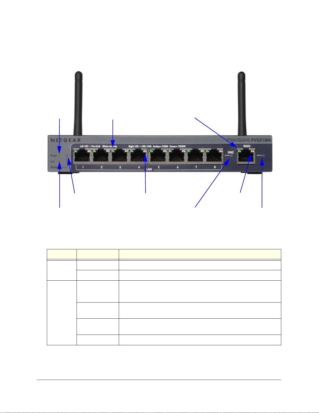
Viewed from left to right, the wireless VPN firewall front panel contains the following ports:
AN Ethernet ports. Eight switched N-way automatic speed negotiating, Auto MDI/MDIX,
• L
Gigabit Ethernet ports with RJ-45 connectors.
• W
AN Ethernet port. One independent N-way automatic speed negotiating, Auto
MDI/MDIX, Gigabit Ethernet port with an RJ-45 connector.
Introduction
15
Page 16
ProSafe Wireless-N 8-Port Gigabit VPN Firewall FVS318N
Power
Test LED
DMZ LED
Left WAN LED
Right WAN LED
Active WAN LED
Wireless LED
LED
Left LAN LEDs
Right LAN LEDs
(green, one for each port)
(one for each port)
(green)
The front panel also contains three groups of status indicator light-emitting diodes (LEDs),
including Power and Test LEDs, LAN LEDs, and WAN LEDs, all of which are explained in
detail in the following table. Some LED explanation is provided on the front panel.
Figure 1.
The following table describes the function of each LED.
Table 1. LED descriptions
LED Activity Description
Power LED On (green) Power is supplied to the wireless VPN firewall.
Off Power is not supplied to the wireless VPN firewall.
Test LED On (amber) during
startup.
On (amber) during
any other time
Blinking (amber) The wireless VPN firewall is writing to flash memory (during upgrading or
Off The wireless VPN firewall has booted successfully.
Test mode. The wireless VPN firewall is initializing. After approximately 2
minutes, when the wireless VPN firewall has completed its initialization, the
Test LED goes off.
The initialization has failed, or a hardware failure has occurred.
resetting to defaults).
Introduction
16
Page 17
ProSafe Wireless-N 8-Port Gigabit VPN Firewall FVS318N
Table 1. LED descriptions (continued)
LED Activity Description
LAN Ports
Left LED Off The LAN port has no link.
On (green) The LAN port has detected a link with a connected Ethernet device.
Blinking (green) Data is being transmitted or received by the LAN port.
Right LED Off The LAN port is operating at 10 Mbps.
On (amber) The LAN port is operating at 100 Mbps.
On (green) The LAN port is operating at 1000 Mbps.
DMZ LED Off Port 8 is operating as a normal LAN port.
On (green) Port 8 is operating as a dedicated hardware DMZ port.
WAN Port
Left LED Off The WAN port has no physical link, that is, no Ethernet cable is plugged into
the wireless VPN firewall.
On (green) The WAN port has a valid connection with a device that provides an Internet
connection.
Blinking (green) Data is being transmitted or received by the WAN port.
Right LED Off The WAN port is operating at 10 Mbps.
On (amber) The WAN port is operating at 100 Mbps.
On (green) The WAN port is operating at 1000 Mbps.
Active LED Off There is no link to the Internet.
On (green) There is a link to the Internet.
Introduction
17
Page 18
ProSafe Wireless-N 8-Port Gigabit VPN Firewall FVS318N
(2) Security lock
receptacle
(3) Console port
(4) Factory default
(5) DC power
receptacle
Reset button
Antennas
(6) Power
(1) and (7)
switch
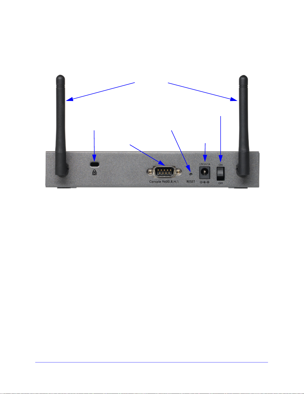
Rear Panel
The rear panel of the wireless VPN firewall includes the antennas, a cable lock receptacle, a
console port, a Reset button, a DC power connection, and a power switch.
Figure 2.
Viewed from left to right, the rear panel contains the following components:
1. Dipole anten
2. Cable security lock recept
3. Console port
connector. The default baud rate is 9600 K. The pinouts are (2) Tx, (3) Rx, (5) and (7) Gnd.
4. Fa
ctory default Reset button. Using a sharp object, press and hold t his button for about
8 seconds until the front panel Test LED flashes to reset the wireless VPN firewall to factory
ault settings. All configuration settings are lost, and the default password is restored.
def
5. DC power plug re
country of sale.
6. Power On/Of
7. Dipole anten
na.
acle.
. Port for connecting to an optional console terminal. The port has a DB9 male
ceptacle. Power input is 12VDC, 1A. The power plug is localized to the
f switch.
na.
Introduction
18
Page 19
ProSafe Wireless-N 8-Port Gigabit VPN Firewall FVS318N
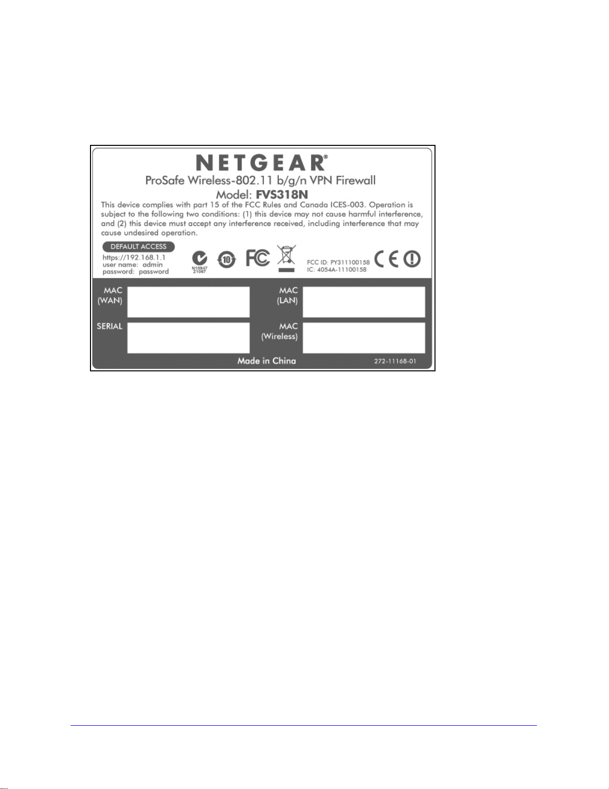
Bottom Panel with Product Label
The product label on the bottom of the wireless VPN firewall’s enclosure displays factory
defaults settings, regulatory compliance, and other information.
Figure 3.
Choose a Location for the Wireless VPN Firewall
The wireless VPN firewall is suitable for use in an office environment where it can be
freestanding (on its runner feet) or mounted into a standard 19-inch equipment rack.
Alternatively, you can rack-mount the wireless VPN firewall in a wiring closet or equipment
room.
Consider the following when deciding where to position the wireless VPN firewall:
he unit is accessible, and cables can be connected easily.
• T
• Cab
• W
• Airflow aro
• T
• T
ling is away from sources of electrical noise. These include lift shafts, microwave
ovens, and air-conditioning units.
ater or moisture cannot enter the case of the unit.
und the unit and through the vents in the side of the case is not restricted.
Provide a minimum of 25 mm or 1 inch clearance.
he air is as free of dust as possible.
emperature operating limits are not likely to be exceeded. Install the unit in a clean,
air-conditioned environment. For information about the recommended operating
temperatures for the wireless VPN firewall, see Appendix A, Default Settings and
Technical Specifications.
Introduction
19
Page 20

ProSafe Wireless-N 8-Port Gigabit VPN Firewall FVS318N
Log In to the Wireless VPN Firewall
Note: To connect the wireless VPN firewall physically to your network,
connect the cables and restart your network according to the
instructions in the ProSafe Wireless-N 8-Port Gigabit VPN Firewall
FVS318N Installation Guide. A PDF of this guide is on the
NETGEAR support website at
http://support.netgear.com/app/products/model/a_id/19435.
To configure the wireless VPN firewall, you nee
Internet Explorer 7.0 or later, Mozilla Firefox 4.0 or later, or Apple Safari 3.0 or later with
JavaScript, cookies, and SSL enabled. (Google Chrome is not supported at this time.)
Although these web browsers are qualified for use with the wireless VPN firewall’s web
management interface, SSL VPN users should choose a browser that supports JavaScript,
Java, cookies, SSL, and ActiveX to take advantage of the full suite of applications. Note that
Java is required only for the SSL VPN portal, not for the web management interface.
To log in to the wireless VPN firewall:
1. S
tart any of the qualified web browsers.
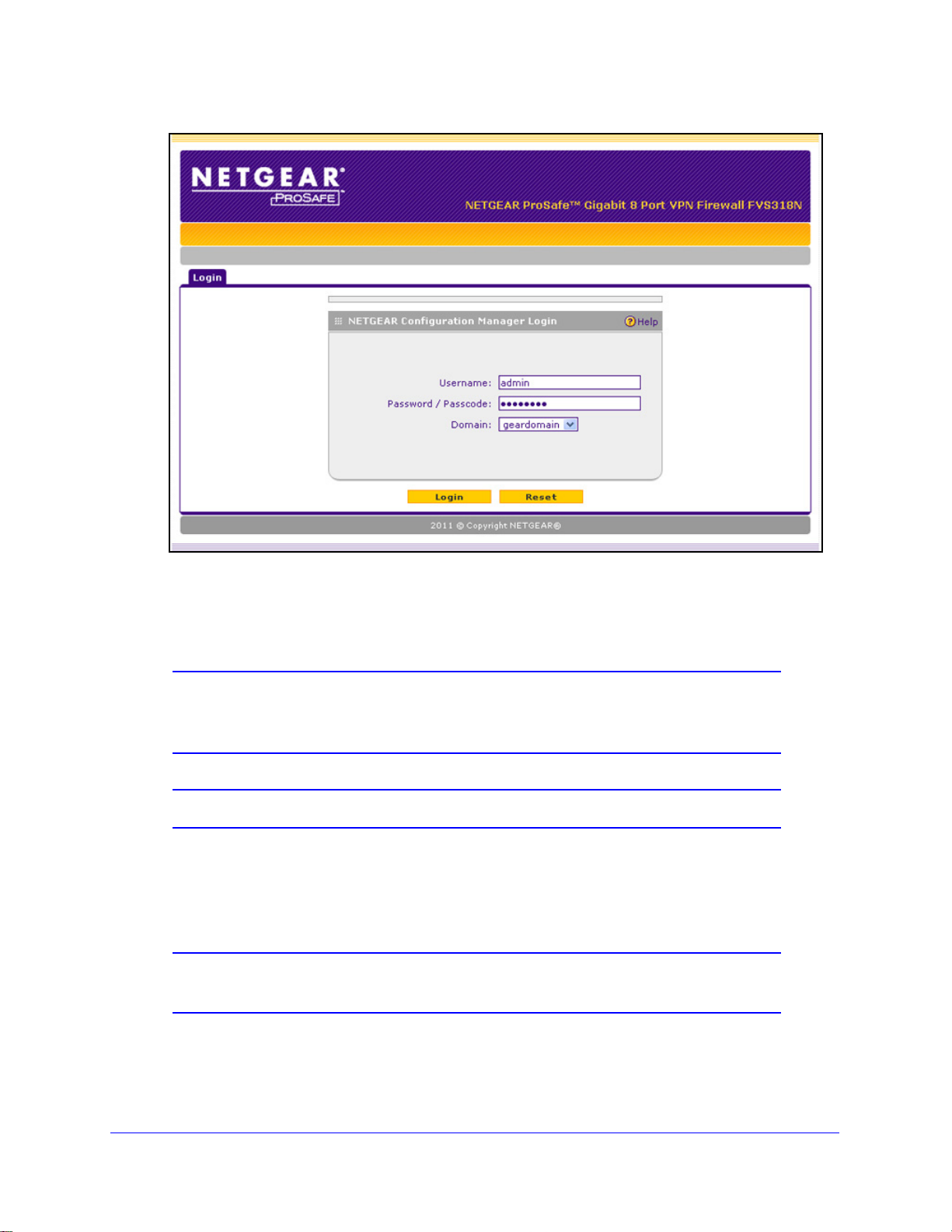
2. In
the address field, enter https://192.168.1.1. The NETGEAR Configuration Manager Login
screen displays in the browser.
Note: The wireless VPN firewall factory default IP address is 192.168.1.1.
If you change the IP address, you need to use the IP address that
you assigned to the wireless VPN firewall to log in to the wireless
VPN firewall.
d to use a web browser such as Microsoft
Introduction
20
Page 21
ProSafe Wireless-N 8-Port Gigabit VPN Firewall FVS318N
Figure 4.
3. In the User Name field, type admin. Use lowercase letters.
4. In the Password / Pa
sscode field, type password. Here, too, use lowercase letters.
Note: The wireless VPN firewall user name and password are not the
same as any user name or password you might use to log in to your
Internet connection.
Note: Leave the domain as it is (geardomain).
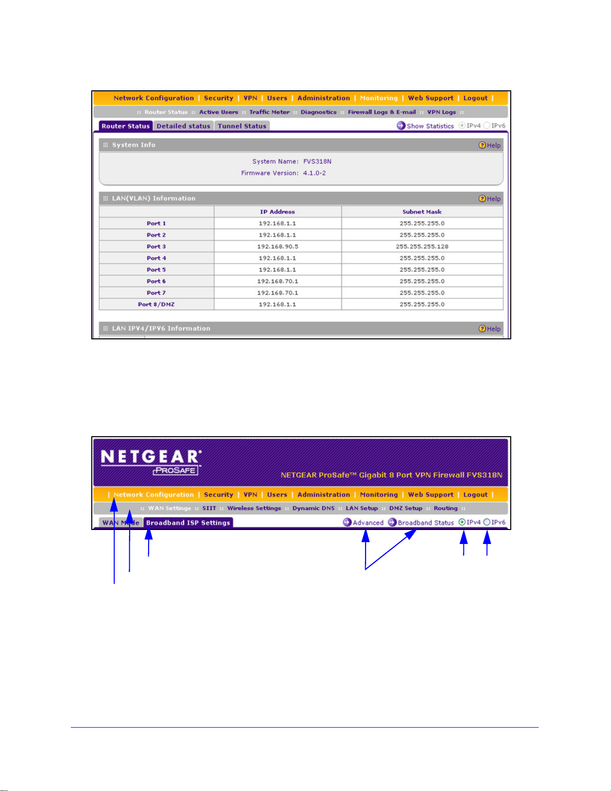
5. Click Login. The web management interface displays, showing the Router Status screen.
The following figure shows the top part of the Router Status screen. For more information,
see View the System Status on p
age 356.
Note: After 5 minutes of inactivity (the default login time-out), you are
automatically logged out.
Introduction
21
Page 22
ProSafe Wireless-N 8-Port Gigabit VPN Firewall FVS318N
1st level: Main navigation menu link (orange)
2nd level: Configuration menu link (gray)
3rd level: Submenu tab (blue)
Option arrows: Additional screen for submenu item
IP radio buttons
Figure 5.
Web Management Interface Menu Layout
The following figure shows the menu at the top the web management interface:
Figure 6.
The web management interface menu consists of the following components:
• 1st le
vel: Main navigation menu links. The main navigation menu in the orange bar
across the top of the web management interface provides access to all the configuration
functions of the wireless VPN firewall, and remains constant. When you select a main
navigation menu link, the letters are displayed in white against an orange background.
Introduction
22
Page 23
ProSafe Wireless-N 8-Port Gigabit VPN Firewall FVS318N
• 2nd level: Configuration menu links. The configuration menu links in the gray bar
(immediately below the main navigation menu bar) change according to the main
navigation menu link that you select. When you select a configuration menu link, the
letters are displayed in white against a gray background.
rd level: Submenu tabs. Each configuration menu item has one or more submenu tabs
• 3
that are listed below the gray menu bar. When you select a submenu tab, the text is
displayed in white against a blue background.
• Option arrows. If there
are additional screens for the submenu item, links to the screens
display on the right side in blue letters against a white background, preceded by a white
arrow in a blue circle.
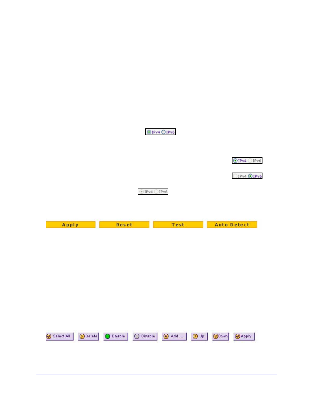
• I
P radio buttons. The IPv4 and IPv6 radio buttons let you select the IP version for the
feature to be configured onscreen. There are four options:
- Both
buttons are operational. You can configure the feature onscreen
for IPv4 functionality or for IPv6 functionality
. After you have correctly configured the
feature for both IP versions, the feature can function with both IP versions
simultaneously.
- T
he IPv4 button is operational but the IPv6 button is disabled. You
can configure the feature onscreen for IPv4 functionality only.
- T
he IPv6 button is operational but the IPv4 button is disabled. You
can configure the feature onscreen for IPv6 functionality only.
- Both
buttons are disabled. IP functionality does not apply.
The bottom of each screen provides action buttons. The nature of the screen determines
which
Figure 7.
action buttons are shown. The following figure shows an example:
Any of the following action buttons might display onscreen (this list might not be complete):
• Appl
• Reset. Rese
• T
• Auto Detect. Enab
y. Save and apply the configuration.
t the configuration to the previously saved configuration.
est. Test the configuration.
le the wireless VPN firewall to detect the configuration automatically
and suggest values for the configuration.
• Can
cel. Cancel the operation.
When a screen includes a table, table buttons display to let you configure the table entries.
he nature of the screen determines which table buttons are shown. The following figure
T
shows an example:
Figure 8.
Introduction
23
Page 24

ProSafe Wireless-N 8-Port Gigabit VPN Firewall FVS318N
Any of the following table buttons might display onscreen:
• Select All. Select all entries in the table.
• Delete. Delete th
• Enable.
• Disable.
• Add. Add a
• Edit. Edit the selected e
• Up. Mo
• Down.
• Apply. Apply the
Almost all screens and sections of screens have an a
help screen, click the (question mark) icon.
Enable the selected entry or entries in the table.
Disable the selected entry or entries in the table.
ve the selected entry up in the table.
Move the selected entry down in the table.
e selected entry or entries from the table.
n entry to the table.
ntry.
selected entry.
ccompanying help screen. To open the
Requirements for Entering IP Addresses
To connect to the wireless VPN firewall, your computer needs to be configured to obtain an IP
address automatically from the wireless VPN firewall, either an IPv4 address through DHCP
or an IPv6 address through DHCPv6, or both.
IPv4
The fourth octet of an IP address needs to be between 0 and 255 (both inclusive). This
requirement applies to any IP address that you enter on a screen of the web management
interface.
IPv6
IPv6 addresses are denoted by eight groups of hexadecimal quartets that are separated by
colons. Any four-digit group of zeroes within an IPv6 address can be reduced to a single zero
or altogether omitted.
The following errors invalidate an IPv6 address:
• Mor
• Mor
• Mor
e than eight groups of hexadecimal quartets
e than four hexadecimal characters in a quartet
e than two colons in a row
Introduction
24
Page 25

2. IPv4 and IPv6 Internet and Broadband
Settings
This chapter explains how to configure the Internet and WAN settings. The chapter contains the
following sections:
• Internet and WAN Configuration Tasks
• Configure the IPv4 Internet Connection and WAN Settings
• Configure the IPv6 Internet Connection and WAN Settings
• Configure Advanced WAN Options and Other Tasks
• What to Do Next
2
Internet and WAN Configuration Tasks
The tasks that are required to complete the Internet connection of your wireless VPN firewall
depend on whether you use an IPv4 connection or an IPv6 connection to your Internet
service provider (ISP).
Note: The wireless VPN firewall supports simultaneous IPv4 and IPv6
connections.
Tasks to Set Up an IPv4 Internet Connection to Your ISP
Complete these four tasks:
1. Con
2. Configure the IPv4 In
figure the IPv4 WAN mode. Select either NAT or classical routing: see Configure
the IPv4 WAN Mode on
following sections:
• Let the Wireless VPN Firewall Automatically Detect and Configure an IPv4 Internet
Connection o
• Manually Configure an IPv4 Internet Connection on p
You can also program the WAN traffic meter if you wish: see Enable the WAN Traffic
Meter on p
age 346.
n page 28
page 27.
ternet connection to your ISP. Connect to your ISP: See one of the
age 31
25
Page 26

ProSafe Wireless-N 8-Port Gigabit VPN Firewall FVS318N
3. (Optional) Configure Dynamic DNS on the WAN port. If required, configure your fully
qualified domain names: See Configure Dynamic DNS o
4. (
Optional) Configure the WAN options. If required, change the factory default MTU size,
port speed, and MAC address of the wireless VPN firewall: See Configure Advanced WAN
Options and Other Tasks on p
need to change the settings.
age 50. These are advanced features, and you usually do not
n page 35.
Tasks to Set Up an IPv6 Internet Connection to Your ISP
Complete these four tasks:
1. Configure
IPv6 traffic: See Configure the IPv6 Routing Mode on p
2. Confi
following sections:
• Use a DHCPv6 Server to Configure an IPv6 Internet Connection o
• Configure a Static IPv6 Internet Connection on p
• Configure a PPPoE IPv6 Internet Connection on p
3. Configure the IPv6
Configure 6to4 Automatic Tunneling on
Tunneling on p
4. (Op
5. (
tional) Configure Stateless IP/ICMP Translation (SIIT). Enable IPv6 d ev ice s th at do
not have permanently assigned IPv4 addresses to communicate with IPv4-only devices:
See Configure Stateless IP/ICMP Translation on p
Optional) Configure the WAN options. If required, change the factory default MTU size,
port speed, and MAC address of the wireless VPN firewall: See Configure Advanced WAN
Options and Other Tasks on p
need to change the settings.
the IPv6 WAN mode. Select the IPv4 / IPv6 mode to support both IPv4 and
age 38.
gure the IPv6 Internet connection to your ISP. Connect to your ISP: See one of the
n page 39
age 41
age 43
tunnels. Enable 6to4 tunnels and configure ISATAP tunnels: See
page 46 and Configure ISATAP Automatic
age 47.
age 49.
age 50. These are advanced features, and you usually do not
Configure the IPv4 Internet Connection and WAN Settings
• Configure the IPv4 WAN Mode
• Let the Wireless VPN Firewall Automatically Detect and Configure an IPv4 Internet
Connection
• Manually Configure an IPv4 Internet Connection
• Configure Dynamic DNS
To set up your wireless VPN firewall for secure IPv4 Internet connections, you need to
deter
mine the IPv4 WAN mode (see the next section) and then configure the IPv4 Internet
connection to your ISP on the WAN port. The web management interface offers two
connection configuration options, discussed in the following sections:
• Let the Wireless VPN Firewall Automatically Detect and Configure an IPv4 Internet
Connection on p
• Manually Configure an IPv4 Internet Connection on p
age 28
age 31
IPv4 and IPv6 Internet and Broadband Settings
26
Page 27

ProSafe Wireless-N 8-Port Gigabit VPN Firewall FVS318N
Configure the IPv4 WAN Mode
By default, IPv4 is supported and functions in NAT mode but can also function in classical
routing mode. IPv4 functions the same way in IPv4-only mode that it does in IPv4 / IPv6
mode. The latter mode adds IPv6 functionality (see Configure the IPv6 Routing Mode on
page 38).
Network Address Translation
Network Address Translation (NAT) allows all computers on your LAN to share a single public
Internet IP address. From the Internet, there is only a single device (the wireless VPN
firewall) and a single IP address. Computers on your LAN can use any private IP address
range, and these IP addresses are not visible from the Internet.
Note the following about NAT:
he wireless VPN firewall uses NAT to select the correct computer (on your LAN) to
• T
receive any incoming data.
• I
f you have only a single public Internet IP address, you need to use NAT (the default
setting).
• I
f your ISP has provided you with multiple public IP addresses, you can use one address
as the primary shared address for Internet access by your computers, and you can map
incoming traffic on the other public IP addresses to specific computers on your LAN. This
one-to-one inbound mapping is configured using an inbound firewall rule.
Classical Routing
In classical routing mode, the wireless VPN firewall performs routing, but without NAT. To
gain Internet access, each computer on your LAN needs to have a valid static Internet IP
address.
If your ISP has allocated a number of static IP addresses to yo u, and you have assigned one
of these addresses to each computer, you can choose classical routing. Or you can use
classical routing for routing private IP addresses within a campus environment.
To view the status of the WAN ports, you can view the Router Status screen (see View the
System Status on page 356).
Configure the IPv4 Routing Mode
To configure the IPv4 routing mode:
1. Select Network Configuratio
n > WAN Settings. The WAN Mode screen displays:
IPv4 and IPv6 Internet and Broadband Settings
27
Page 28

Figure 9.
WARNING:
ProSafe Wireless-N 8-Port Gigabit VPN Firewall FVS318N
2. Select the NA T radio button or the Classical Routing radio button.
Changing the WAN mode causes all LAN WAN and DMZ WAN
inbound rules to revert to default settings.
3. Click Apply to save your settings.
Let the Wireless VPN Firewall Automatically Detect and Configure an IPv4 Internet Connection
To automatically configure the WAN port for an IPv4 connection to the Internet:
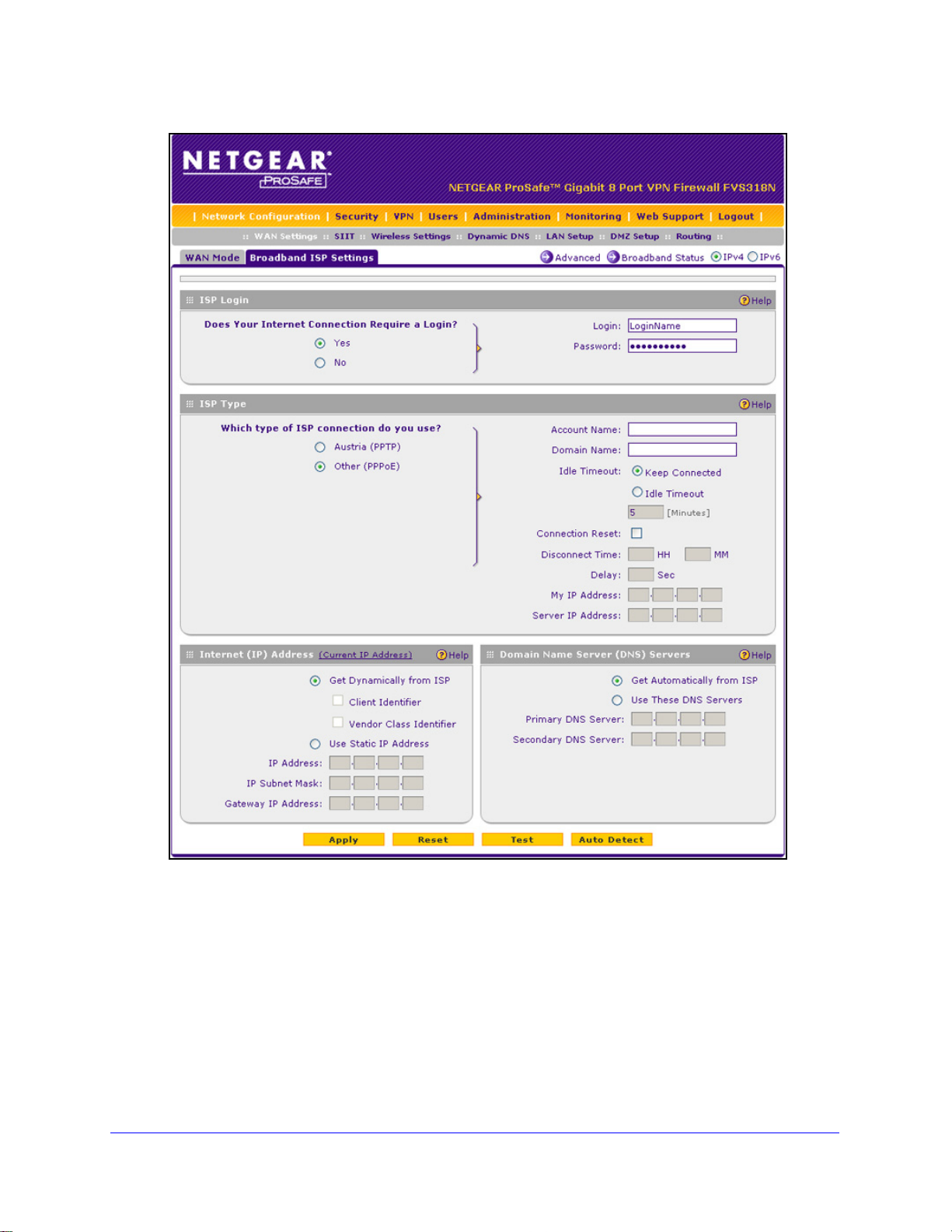
1. Select Netwo
upper right of the screen, the IPv4 radio button is selected by default. The ISP
Broadband Settings screen displays the IPv4 settings:
rk Configuration > WAN Settings > Broadband ISP Settings. In the
IPv4 and IPv6 Internet and Broadband Settings
28
Page 29
ProSafe Wireless-N 8-Port Gigabit VPN Firewall FVS318N
Figure 10.
2. Click the Auto Detect button at the bottom of the screen. The autodetect process probes
the WAN port for a range of connection methods and suggests one that your ISP is most
likely to support.
The autodetect process returns one of the following results:
f the autodetect process is successful, a status bar at the top of the screen displays
• I
the results (for example, DHCP service detected).
• I
f the autodetect process senses a connection method that requires input from you, it
prompts you for the information. The following table explains the settings that you
might have to enter:
IPv4 and IPv6 Internet and Broadband Settings
29
Page 30
ProSafe Wireless-N 8-Port Gigabit VPN Firewall FVS318N
Table 2. IPv4 Internet connection methods
Connection Method Manual Data Input Required
DHCP (Dynamic IP) No manual data input is required.
PPPoE The following fields are required:
• Login
• Password
• Account Name
• Domain Name
PPTP The following fields are required:
• Login
• Password
• Account Name
• Domain Name
• My IP Address
• Server IP Address
Fixed (Static) IP The following fields are required:
• IP Address
• IP Subnet Mask
• Gateway IP Address
• Primary DNS Server
• Secondary DNS Server
• If the autodetect process does not find a connection, you are prompted either to
check the physical connection between your wireless VPN firewall and the cable, DSL
line, or satellite or wireless Internet dish, or to check your wireless VPN firewa ll’s MAC
address. For more information, see Configure Advanced WAN Options and Other
Tasks o
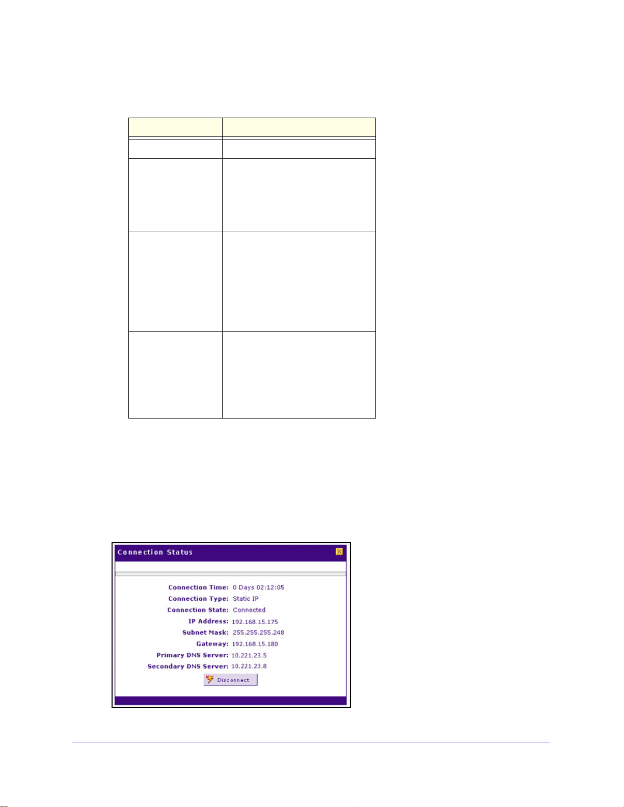
3. T
o verify the connection, click the Broadband Status option arrow in the upper right of the
n page 50 and Troubleshoot the ISP Connection on page 382.
screen to display the Connection Status pop-up screen. (The following figure shows a static
IP address configuration.)
Figure 11.
IPv4 and IPv6 Internet and Broadband Settings
30
Page 31

ProSafe Wireless-N 8-Port Gigabit VPN Firewall FVS318N
The Connection Status screen should show a valid IP address and gateway, and you are
connected to the Internet. If the configuration was not successful, skip ahead to Manually
Configure an IPv4 Internet Connection on p
Connection o
n page 382.
age 31, or see Troubleshoot the ISP
Note: For more information about the Connection S t atus screen, see View
the WAN Port Status on page 367.
Manually Configure an IPv4 Internet Connection
Unless your ISP automatically assigns your configuration through a DHCP server, you need
to obtain configuration parameters from your ISP to manually establish an Internet
connection. The required parameters for various connection types are listed in Table 2 on
page 30.
To manually configure the IPv4 broadband ISP settings:
1. Select Network Configuratio
n > WAN Settings > Broadband ISP Settings. In the
upper right of the screen, the IPv4 radio button is selected by default. The ISP
Broadband Settings screen displays the IPv4 settings (see Figure 10 on p
2. Locate the ISP Login
Figure 12.
section on the screen:
age 29).
In the ISP Login section, select one of the following options:
• I
f your ISP requires an initial login to establish an Internet connection, select Yes.
(The default is No.)
• I
f a login is not required, select No, and ignore the Login and Password fields.
3. If you se
lected Yes, enter the login name in the Login field and the password in the
Password field. This information is provided by your ISP.
4. In the ISP T
ype section of the screen, select the type of ISP connection that you use from
the two listed options. By default, Austria (PPTP) is selected, as shown in the following
figure:
IPv4 and IPv6 Internet and Broadband Settings
31
Page 32

ProSafe Wireless-N 8-Port Gigabit VPN Firewall FVS318N
Figure 13.
5. If your connection is PPTP or PPPoE, your ISP requires an initial login. Enter the settings as
explained in the following table:
Table 3. PPTP and PPPoE settings
Setting Description
Austria (PPTP)
Note: For login
and password
information, see
Step 2 and Step 3.
If your ISP is Austria Telecom or any other ISP th
radio button, and enter the following settings:
Account Name The account name is also known as the host name or system name.
Enter the valid account name for the PPTP connection (usually your
email ID assigned by your ISP). Some ISPs require you to enter
your full email address here.
Domain Name Your domain name or workgroup name assigned by your ISP, or
your ISP’s domain name. You can leave this fi eld blank.
Idle Timeout Select the Keep Connected radio button to keep the connection
always on. To log out after the connection is idle for a period, select
the Idle Timeout radio button and, in the Idle Timeout field, enter the
number of minutes to wait before disconnecting. This is useful if your
ISP charges you based on the period that you have logged in.
My IP Address The IP address assigned by the ISP to make the connection with the
ISP server.
Server IP
Address
The IP address of the PPTP server.
at uses PPTP for login, select this
IPv4 and IPv6 Internet and Broadband Settings
32
Page 33

ProSafe Wireless-N 8-Port Gigabit VPN Firewall FVS318N
Table 3. PPTP and PPPoE settings (continued)
Setting Description
Other (PPPoE)
Note: For login
ssword
and pa
information, see
Step 2 and Step 3.
If you have installed login software, then your connection type is PPPoE. Select this
radio button, and enter the following settings:
Account Name The valid account name for the PPPoE connection.
Domain Name The name of your ISP’s domain or your domain name if your ISP
has assigned one. You can leave this field blank.
Idle Timeout Select the Keep Connected radio button to keep the connection
always on. To log out after the connection is idle for a period, select
the Idle Timeout radio button and, in the Idle T imeout field, enter the
number of minutes to wait before disconnecting. This is useful if your
ISP charges you based on the period that you have logged in.
Connection
Reset
Select the Connection Reset check box to specify a time when the
PPPoE WAN connection is reset, that is, the connection is
disconnected momentarily and then reestablished. Then specify the
disconnect time and delay.
Disconnect
Time
Delay Specify the period in seconds after which the
Specify the hour and minutes when the connection
should be disconnected.
connection should be reestablished.
6. In the Internet (IP) Address section of the screen (see the following figure), configure the IP
address settings as explained in the following table. Click the Current IP Address link to
see the currently assigned IP address.
IPv4 and IPv6 Internet and Broadband Settings
33
Page 34

ProSafe Wireless-N 8-Port Gigabit VPN Firewall FVS318N
Table 4. Internet IP address settings
Setting Description
Get Dynamically
from ISP
Use Static IP
Address
If your ISP has not assigned you a static IP address, select the Get Dynamically from
ISP radio button. The ISP automatically assigns an IP address to the wireless VPN
firewall using DHCP network protocol.
Client Identifier If your ISP requires the client identifier information to assign an
IP address using DHCP, select the Client Identifier check box.
Vendor Class Identifier If your ISP requires the vendor class identifier information to
assign an IP address using DHCP, select the Vendor Class
Identifier check box.
If your ISP has assigned you a fixed (static or permanent) IP address, select the Use
Static IP Address radio button, and enter the following settings:
IP Address The static IP address assigned to you. This address identifies
the wireless VPN firewall to your ISP.
IP Subnet Mask The subnet mask is usually provided by your ISP.
Gateway IP Address The IP address of the ISP’s gateway is usually provided by
your ISP.
7. In the Domain Name Server (DNS) Servers section of the screen (see the following figure),
specify the DNS settings as explained in the following table.
Figure 14.
Table 5. DNS server settings
Setting Description
Get Automatically
from ISP
Use These DNS
Servers
If your ISP has not assigned any Domain Name Server (DNS) addresses, select the
Get Automatically from ISP radio button.
If your ISP has assigned DNS addresses, select the Use These DNS Servers radio
button. Make sure that you fill in valid DNS server IP addresses in the fields. Incorrect
DNS entries might cause connectivity issues.
Primary DNS Server The IP address of the primary DNS server.
Secondary DNS Server The IP address of the secondary DNS server.
IPv4 and IPv6 Internet and Broadband Settings
34
Page 35

ProSafe Wireless-N 8-Port Gigabit VPN Firewall FVS318N
8. Click Apply to save your changes.
9. Click Te
st to evaluate your entries. The wireless VPN firewall attempts to make a connection
according to the settings that you entered.
10. T
o verify the connection, click the Broadband Status option arrow in the upper right of the
screen to display the Connection Status pop-up screen. (The following figure shows a
PPPoE configuration; the IP addresses are not related to any other examples in this
manual.)
Figure 15.
Note: If your ISP requires MAC authentication and another MAC address
has been previously registered with your ISP, then you need to enter
that address on the Broadband Advanced Options screen for the
WAN interface (see
Configure Advanced WAN Options and Other
Tasks on page 50).
Configure Dynamic DNS
Dynamic DNS (DDNS) is an Internet service that allows devices with varying public IPv4
addresses to be located using Internet domain names. To use DDNS, you need to set up an
account with a DDNS provider such as DynDNS.org, TZO.com, Oray .net, or 3322.org. (Links
to DynDNS, TZO, Oray, and 3322 are provided for your convenience as option arrows on the
DDNS configuration screens.) The wireless VPN firewall firmware includes software that
notifies DDNS servers of changes in the WAN IP address so that the services running on this
network can be accessed by others on the Internet.
If your network has a permanently assigned IP address, you can register a domain name and
have that name linked with your IP address by public Domain Name Servers (DNS).
However, if your Inte rnet account uses a dynamically assign ed IP address, you will no t know
in advance what your IP address will be, and the address can change frequently—hence, the
need for a commercial DDNS service, which allows you to register an extension to its
domain, and restores DNS requests for the resulting fully qualified domain name (FQDN) to
your frequently changing IP address.
IPv4 and IPv6 Internet and Broadband Settings
35
Page 36

ProSafe Wireless-N 8-Port Gigabit VPN Firewall FVS318N
After you have configured your account information on the wireless VPN firewall, when your
ISP-assigned IP address changes, your wireless VPN firewall automatically contacts your
DDNS service provider, logs in to your account, and registers your new IP address.
Note: If your ISP assigns a private WAN IP address such as 192.168.x.x
or 10.x.x.x, the DDNS service does not work because private
addresses are not routed on the Internet.
To configure DDNS:
1. Select Netwo
rk Configuration > Dynamic DNS. The Dynamic DNS screen displays
(see the following figure).
2. Click th
• Dynamic
• DN
• DN
• 3322
e submenu tab for your DDNS service provider:
DNS for DynDNS.org (which is shown in the following figure)
S TZO for TZO.com
S Oray for Oray.net
DDNS for 3322.org
Figure 16.
3. Click the Information option arrow in the upper right of a DNS screen for registration
information (for example, DynDNS Information).
Figure 17.
IPv4 and IPv6 Internet and Broadband Settings
36
Page 37

ProSafe Wireless-N 8-Port Gigabit VPN Firewall FVS318N
4. Access the website of the DDNS service provider, and register for an account (for example,
for DynDNS.org, go to http://www .dyndns.com/).
5. Conf
igure the DDNS service settings as explained in the following table:
Table 6. DDNS service settings
Setting Description
Change DNS to
(DynDNS, TZO,
Oray, or 3322)
Change DNS to
(DynDNS, TZO,
Oray, or 3322)
(continued)
Select the Yes radio button to enable the DDNS service. The fields that display on the
screen depend on the DDNS service provider that you have selected. Enter the following
settings:
Host and Domain Name The host and domain name for the DDNS service.
Username or
User Email Address
Password or User Key The password that is used for DDNS ser ver authentication.
Use wildcards If your DDNS provider allows the use of wildcards in resolving
Update every 30 days If your WAN IP address does not change often, you might
The user name or email address for DDNS server
authentication.
your URL, you can select the Use wildcards check box to
activate this feature. For example, the wildcard feature
causes *.yourhost.dyndns.org to be aliased to the same IP
address as yourhost.dyndns.org.
need to force a periodic update to the DDNS service to
prevent your account from expiring. If the Update every 30
days check box displays, select it to enable a periodic
update.
6. Click App
ly to save your configuration.
Configure the IPv6 Internet Connection and WAN Settings
• Configure the IPv6 Routing Mode
• Use a DHCPv6 Server to Configure an IPv6 Internet Connection
• Configure a Static IPv6 Internet Connection
• Configure a PPPoE IPv6 Internet Connection
• Configure 6to4 Automatic Tunneling
• Configure ISATAP Automatic Tunneling
• View the Tunnel Status and IPv6 Addresses
• Configure Stateless IP/ICMP Translation
The nature of your IPv6 network determines how you need to configure the IPv6 Internet
conne
• Nati
ction:
ve IPv6 network. Your network is a native IPv6 network if the wireless VPN firewall
has an IPv6 address and is connected to an IPv6 ISP and if your network consists of
IPv6-only devices. However, because we are in a IPv4-to-IPv6 transition period, native
IPv6 is not yet very common.
IPv4 and IPv6 Internet and Broadband Settings
37
Page 38

ProSafe Wireless-N 8-Port Gigabit VPN Firewall FVS318N
• Isolated IPv6 network. If your network is an isolated IPv6 network that is not connected
to an IPv6 ISP, you need to make sure that the IPv6 packets can travel over the IPv4
Internet backbone; you do this by enabling automatic 6to4 tunneling (see Configure 6to4
Automatic Tunneling o
• Mix
ed network with IPv4 and IPv6 devices. If your network is an IPv4 network that
n page 46).
consists of both IPv4 and IPv6 devices, you need to make sure that the IPv6 p acket s can
travel over the IPv4 intranet; you do this by enabling and configuring ISATAP tunneling
(see Configure ISATAP Automatic Tunneling on p
age 47).
Note: A network can be both an isolated IPv6 network and a mixed
network with IPv4 and IPv6 devices.
After you have configured the IPv6 routing mode (see the next section), you need to
configure the WAN port with a global unicast address to enable secure IPv6 Internet
connections on your wireless VPN firewall. A global unicast address is a public and routable
IPv6 WAN address that can be statically or dynamically assigned. The web management
interface offers two connection configuration options:
• Automatic co
Configure an IPv6 Internet Connection o
• Ma
nual configuration of the network connection (see Configure a Static IPv6 Internet
Connection on p
nfiguration of the network connection (see Use a DHCPv6 Server to
n page 39)
age 41 or Configure a PPPoE IPv6 Internet Connection on page 43)
Configure the IPv6 Routing Mode
By default, the wireless VPN firewall supports IPv4 only. To use IPv6, you need to enable the
wireless VPN firewall to support both devices with IPv4 addresses and devices with IPv6
addresses. The routing mode does not include an IPv6-only option; however, you can still
configure a native IPv6 network if your ISP supports IPv6. These are the options:
• IPv4-on
IPv4 addresses.
• IPv4/IPv6
IPv4 addresses and devices that have IPv6 addresses.
ly mode. The wireless VPN firewall communicates only with devices that have
mode. The wireless VPN firewall communicates with both devices that have
Note: IPv6 always functions in classical routing mode between the WAN
interface and the LAN interfaces; NAT does not apply to IPv6.
To configure the IPv6 routing mode:
1. Select Netwo
rk Configuration > WAN Settings. The WAN Mode screen displays:
IPv4 and IPv6 Internet and Broadband Settings
38
Page 39

ProSafe Wireless-N 8-Port Gigabit VPN Firewall FVS318N
WARNING:
Figure 18.
2. Select the IPv4 / IPv6 mode radio button. By default, the IPv4 only mode radio button is
selected, and IPv6 is disabled.
Changing the IP routing mode causes the wireless VPN firewall to
reboot.
3. Click Apply to save your changes.
Use a DHCPv6 Server to Configure an IPv6 Internet Connection
The wireless VPN firewall can autoconfigure its ISP settings through a DHCPv6 server by
using either stateless or stateful address autoconfiguration:
• S
tateless address autoconfiguration. The wireless VPN firewall generates its own IP
address by using a combination of locally available information and router
advertisements, but receives DNS server information from a DHCPv6 server.
Router advertisements include a prefix that ident
the WAN port. The IP address is formed by combining this prefix and the MAC address of
the WAN port. The IP address is a dynamic address.
As an option for stateless address autoconfiguration, the ISP’s st
can assign a prefix through prefix delegation. The wireless VPN firewall’s own stateless
DHCPv6 server can assign this prefix to its IPv6 LAN clients. For more information about
prefix delegation, see Stateless DHCPv6 Server With Prefix Delegation on p
ifies the subnet that is associated with
ateful DHCPv6 server
age 74.
IPv4 and IPv6 Internet and Broadband Settings
39
Page 40

ProSafe Wireless-N 8-Port Gigabit VPN Firewall FVS318N
• Stateful address autoconfiguration. The wireless VPN firewall obtains an interface
address, configuration information such as DNS server information, and other parameters
from a DHCPv6 server. The IP address is a dynamic address.
To automatically configure the WAN port for an IPv6 connection to the Internet:
1. Select Netwo
2. In
the upper right of the screen, select the IPv6 radio button. The ISP Broadband Settings
rk Configuration > WAN Settings > Broadband ISP Settings.
screen displays the IPv6 settings:
Figure 19.
3. In the Internet Address section of the screen, from the IPv6 drop-down list, select DHCPv6.
the DHCPv6 section of the screen, select one of the following radio buttons:
4. In
tateless Address Auto Configuration
• S
tateful Address Auto Configuration
• S
IPv4 and IPv6 Internet and Broadband Settings
40
Page 41

ProSafe Wireless-N 8-Port Gigabit VPN Firewall FVS318N
5. As an optional step: If you have selected the Stateless Address Auto Configuration radio
button, you can select the Prefix Delegation check bo x:
• Prefix
delegation check box is selected. A prefix is assigned by the ISP’s stateful
DHCPv6 server through prefix delegation, for example, 2001:db8:: /64. The wireless
VPN firewall’s own stateless DHCPv6 server can assign this prefix to its IPv6 LAN
clients. For more information about prefix delegation, see Stateless DHCPv6 Server
With Prefix Delegation on p
• Prefix
delegation check box is cleared. Prefix delegation is disabled. This is the
age 74.
default setting.
6. Click App
7. T
o verify the connection, click the Status option arrow in the upper right of the screen to
ly to save your changes.
display the Connection Status pop-up screen. (The following figure shows a dynamic IP
address configuration.)
Figure 20.
The Connection Status screen should show a valid IP address and gateway, and you are
connected to the Internet. If the configuration was not successful, see Troubleshoot the
ISP Connection on
page 382.
Note: For more information about the Connection S t atus screen, see View
the WAN Port Status on page 367.
Configure a Static IPv6 Internet Connection
To configure a static IPv6 or PPPoE IPv6 Internet connection, you need to enter the IPv6
address information that you should have received from your ISP.
To configure static IPv6 broadband ISP settings:
1. Select Network Configuratio
2. In the upper
right of the screen, select the IPv6 radio button. The ISP Broadband Settings
screen displays the IPv6 settings:
IPv4 and IPv6 Internet and Broadband Settings
n > WAN Settings > Broadband ISP Settings.
41
Page 42

ProSafe Wireless-N 8-Port Gigabit VPN Firewall FVS318N
Figure 21.
3. In the Internet Address section of the screen, from the IPv6 drop-down list, select Static
IPv6.
4. In
the Static IP Address section of the screen, enter the settings as explained in the following
table. You should have received static IPv6 address information from your IPv6 ISP:
Table 7. Broadband ISP Settings screen settings for a static IPv6 address
Setting Description
IPv6 Address The IP address that your ISP assigned to you. Enter the address in one of the
following formats (all four examples specify the same IPv6 address):
• 2001:db8:0000:0000:020f:24ff:febf:dbcb
• 2001:db8:0:0:20f:24f
• 2001:db8::20f:24ff:febf:dbcb
• 2001:db8:0:0:20f:24f
IPv6 Prefix Length The prefix length that your ISP assign
Default IPv6 Gateway The IPv6 IP address of the ISP’s default IPv6 gateway.
Primary DNS Server The IPv6 IP address of the ISP’s primary DNS server.
Secondary DNS Server The IPv6 IP address of the ISP’s secondary DNS server.
f:febf:dbcb
f:128.141.49.32
ed to you, typically 64.
IPv4 and IPv6 Internet and Broadband Settings
42
Page 43

ProSafe Wireless-N 8-Port Gigabit VPN Firewall FVS318N
5. Click Apply to save your changes.
o verify the connection, click the Status option arrow in the upper right of the screen to
6. T
display the Connection Status pop-up screen. (The following figure shows a static IP
address configuration; the IP addresses are not related to any other examples in this
manual.)
Figure 22.
The Connection Status screen should show a valid IP address and gateway, and you are
connected to the Internet. If the configuration was not successful, see Troubleshoot the
ISP Connection on
page 382.
Note: For more information about the Connection S t atus screen, see View
the WAN Port Status on page 367.
Note: If your ISP requires MAC authentication and another MAC address
has been previously registered with your ISP, then you need to enter
that address on the Broadband Advanced Options screen for the
corresponding WAN interface (see
Configure Advanced WAN
Options and Other Tasks on page 50).
Configure a PPPoE IPv6 Internet Connection
To configure a PPPoE IPv6 Internet connection, you need to enter the PPPoE IPv6
information that you should have received from your ISP.
To configure PPPoE IPv6 broadband ISP settings:
1. Select Network Configuratio
2. In the upper
right of the screen, select the IPv6 radio button. The ISP Broadband Settings
n > WAN Settings > Broadband ISP Settings.
screen displays the IPv6 settings:
IPv4 and IPv6 Internet and Broadband Settings
43
Page 44

ProSafe Wireless-N 8-Port Gigabit VPN Firewall FVS318N
Figure 23.
3. In the Internet Address section of the screen, from the IPv6 drop-down list, select PPPoE.
4. In
the PPPoE IPv6 section of the screen, enter the settings as explained in the following
table. You should have received PPPoE IPv6 information from your ISP:
Table 8. Broadband ISP Settings screen settings for a PPPoE IPv6 connection
Setting Description
User Name The PPPoE user name that is provided by your ISP.
Password The PPPoE password that is provided by your ISP.
IPv4 and IPv6 Internet and Broadband Settings
44
Page 45

ProSafe Wireless-N 8-Port Gigabit VPN Firewall FVS318N
Table 8. Broadband ISP Settings screen settings for a PPPoE IPv6 connection (continued)
Setting Description
DHCPv6 Option From the DHCPv6 Option drop-down list, select one of the following DHCPv6
server options, as directed by your ISP:
• Disable-DHCPv6. DHCPv6 is disab
the Primary DNS Server and Secondary DNS Server fields in order to receive
an IP address from the ISP.
Pv6 StatelessMode. The wireless VPN firewall generates its own IP
• DHC
address by using a combination of locally availa ble information and router
advertisements, but receives DNS server information from the ISP’s DHCPv6
server. Router advertisements include a prefix that identifies the subnet that is
associated with the WAN port. The IP address is formed by combining this
prefix and the MAC address of the WAN port. The IP address is a dynamic
address.
Pv6 StatefulMode. The wireless VPN firewall obtains an interface
• DHC
address, configuration information such as DNS server information, and othe r
parameters from the ISP’s DHCPv6 server. The IP address is a dynamic
address.
CPv6 Prefix Delegation. The wireless VPN firewall obtains a prefix from the
• DH
ISP’s DHCPv6 server through prefix delegation, for example, 2001:db8:: /64 .
The wireless VPN firewall’s own stateless DHCPv6 server can assign this prefix
to its IPv6 LAN clients. For more information about prefix delegation, see
Stateless DHCPv6 Server W
led. You need to specify the DNS servers in
ith Prefix Delegation on page 74.
Primary DNS Server If you have selected the Disable-DHCPv6 from the DHCPv6 Options drop-down
list, the IPv6 IP address of the ISP’s primary DNS server .
Secondary DNS Server If you have selected the Disable-DHCPv6 from the DHCPv6 Options drop-down
list, the IPv6 IP address of the ISP’s secondary DNS server.
5. Click Apply to save your changes.
6. T
o verify the connection, click the Status option arrow in the upper right of the screen to
display the Connection Status pop-up screen (see Figure 22 on p
age 43, which shows a
static IP address configuration; the screen for PPPoE is very similar.)
The Connection Status screen should show a valid IP a
ddress and gateway, and you are
connected to the Internet. If the configuration was not successful, see Troubleshoot the
ISP Connection on
page 382.
Note: For more information about the Connection S t atus screen, see View
the WAN Port Status on page 367.
Note: If your ISP requires MAC authentication and another MAC address
has been previously registered with your ISP, then you need to enter
that address on the Broadband Advanced Options screen for the
corresponding WAN interface (see
Configure Advanced WAN
Options and Other Tasks on page 50).
IPv4 and IPv6 Internet and Broadband Settings
45
Page 46

ProSafe Wireless-N 8-Port Gigabit VPN Firewall FVS318N
Configure 6to4 Automatic Tunneling
If your network is an isolated IPv6 network that is not connected to an IPv6 ISP, you need to
make sure that the IPv6 packets can travel over the IPv4 Internet backbone by enabling
automatic 6to4 tunneling.
6to4 is a WAN tunnel mechanism for automat ic tunneling of IPv6 traffic between a device with
an IPv6 address and a device with an IPv4 address, or the other way around. 6to4 tunneling
is used to transfer IPv6 traffic between LAN IPv6 hosts and W AN IPv6 networks over the IPv4
network.
With 6to4 tunnels, IPv6 packets are embedded within the IPv4 packet and then transported
over the IPv4 network. You do not need to specify remote tunnel endpoints, which are
automatically determined by relay routers on the Internet. You cannot use 6to4 tunnels for
traffic between IPv4-only devices and IPv6-only devices.
Note: If the wireless VPN firewall functions as the endpoint for 6to4
tunnels in your network, make sure that the wireless VPN firewall
has a static IPv4 address (see
Connection on
page 31). A dynamic IPv4 address can cause routing
problems on the 6to4 tunnels.
Manually Configure an IPv4 Internet
Note: If you do not use a stateful DHCPv6 server in your LAN, you need to
configure the Router Advertisement Daemon (RADVD), and set up
6to4 advertisement prefixes for 6to4 tunneling to function correctly.
For more information, see Manage the IPv6 LAN on page 73.
Typically, 6to4 tunnel addresses start with a 2002 prefix (decimal notification). On the
wireless VPN firewall, a 6to
4 tunnel is indicated by sit0-WAN1 (see View the Tunnel Status
and IPv6 Addresses on page 49).
To enable 6to4 automatic tunneling:
1. Select Netwo
rk Configuration > WAN Settings > 6 to 4 Tunneling.
Figure 24.
IPv4 and IPv6 Internet and Broadband Settings
46
Page 47

ProSafe Wireless-N 8-Port Gigabit VPN Firewall FVS318N
2. Select the Enable Automatic Tunneling check box.
3. Click App
ly to save your changes.
Configure ISATAP Automatic Tunneling
If your network is an IPv4 network or IPv6 network that consists of both IPv4 and IPv6
devices, you need to make sure that the IPv6 packets can travel over the IPv4 intranet by
enabling and configuring Intra-Site Automatic Tunnel Addressing Protocol (ISATAP)
tunneling.
ISATAP is a LAN tunnel mechanism in which the IPv4 network functions as a virtual IPv6
local link. Each IPv4 address is mapped to a link-local IPv6 address, that is, the IPv4 address
is used in the interface portion of the IPv6 address. ISATAP tunneling is used intra-site, that
is, between addresses in the LAN. For more information about link-local addresses, see
Manage the IPv6 LAN on page 73.
Note: If you do not use a stateful DHCPv6 server in your LAN, yo u need to
configure the Router Advertisement Daemon (RADVD), and set up
ISATAP advertisement prefixes (which are referred to as
Global/Local/ISATAP prefixes) for ISATAP tunneling to function
correctly. For more information, see
page 73.
Manage the IPv6 LAN on
The wireless VPN firewall determines the link-local addr
address with the 32 bits of the IPv4 host address:
or a unique global address:
• F
fe80:0000:0000:0000:0000:5efe (or fe80::5efe) is concatenated with the IPv4 address.
or example, fe80::5efe with 10.29.33.4 becomes fe80::5efe:10.29.33.4, or in
F
hexadecimal format, fe80::5efe:a1d:2104.
• F
or a private address:
fe80:0000:0000:0000:0200:5efe (or fe80::200:5efe) is concatenated with the IPv4
a
ddress. For example, fe80::200:5efe with 192.168.1.1 becomes
fe80::200:5efe:192.168.1.1, or in hexadecimal format, fe80::200:5efe:c0a8:101.
To configure an ISATAP tunnel:
1. Select Network Configuratio
n > WAN Settings > ISATAP Tunnels. The ISATAP
Tunnels screen displays. (The following figure shows some examples.)
ess by concatenating the IPv6
IPv4 and IPv6 Internet and Broadband Settings
47
Page 48

ProSafe Wireless-N 8-Port Gigabit VPN Firewall FVS318N
Figure 25.
2. Click the Add table button under the List of Available ISATAP Tunnels table. The Add
ISATAP Tunnel screen displays:
Figure 26.
3. Specify the tunnel settings as explained in the following table.
Table 9. Add ISATAP Tunnel screen settings
Setting Description
ISATAP Subnet Prefix The IPv6 prefix for the tunnel.
Local End Point
Address
IPv4 Address If you select Other IP from the Local
4. Click Apply to
save your changes.
From the drop-down list, select the type of local address:
• LAN. The local endpoint address is the address of the default VLAN.
• Other IP. The local endpoint address is another LAN IP address that you need
to specify in the IPv4 Address fields.
IPv4 address.
To edit an ISATAP tunnel:
1. On
the ISATAP Tunnels screen, click the Edit button in the Action column for the tunnel
that you want to modify. The Edit ISATAP Tunnel screen displays. This screen is
identical to the Add ISATAP Tunnel screen.
End Point Address drop-down list, enter the
IPv4 and IPv6 Internet and Broadband Settings
48
Page 49

ProSafe Wireless-N 8-Port Gigabit VPN Firewall FVS318N
2. Modify the settings as explained in the previous table.
3. Click App
To delete one or more tunnels:
1. On th
want to delete, or click the Select All table button to select all tunnels.
2. Click the Del
ly to save your settings.
e ISATAP Tunnels screen, select the check box to the left of each tunnel that you
ete table button.
View the Tunnel Status and IPv6 Addresses
The IPv6 Tunnel Status screen displays the status of all active 6to4 and ISATAP tunnels and
their IPv6 addresses.
To view the status of the tunnels and IPv6 addresses:
Select Monitoring > Router Status > Tunnel Status. The Tunnel Status screen displays:
Figure 27.
The IPv6 Tunnel Status table shows the following fields:
• T
unnel Name. The tunnel name for the 6to4 tunnel is always sit0-WAN1 (SIT stands for
simple Internet transition); the tunnel name for an ISATAP tunnel is isatapx-LAN, in wh ich
x is an integer.
• I
Pv6 Address. The IPv6 address of the local tunnel endpoint.
Configure Stateless IP/ICMP Translation
Stateless IP/ICMP Translation (SIIT) is a transition mechanism algorithm that translates
between IPv4 and IPv6 packet headers. Using SIIT, an IPv6 device that does not have a
permanently assigned IPv4 addresses can communicate with an IPv4-only device.
SIIT functions with IPv4-translated addresses, which are addresses of the format
0::ffff:0:0:0/96 for IPv6-enabled devices. You can substitute an IPv4 address in the format
a.b.c.d for part of the IPv6 address so that the IPv4-translated address becomes
0::ffff:0:a.b.c.d/96.
IPv4 and IPv6 Internet and Broadband Settings
49
Page 50

ProSafe Wireless-N 8-Port Gigabit VPN Firewall FVS318N
For SIIT to function, the routing mode needs to be IPv4 / IPv6. NETGEAR’s implementation of
SIIT lets you enter a single IPv4 address on the SIIT screen. This IPv4 address is then used
in the IPv4-translated address for IPv6 devices to enable communication between IPv4-only
devices on the wireless VPN firewall’s LAN and IPv6-only devices on the WAN.
To configure SIIT:
1. Select Network Configuration > SIIT. The SIIT screen displays:
Figure 28.
2. Select the Enable SIIT check box.
3. In
the SIIT Address fields, enter the IPv4 address that should be used in the IPv4-translated
address for IPv6 devices.
4. Click Apply to
save your changes.
Configure Advanced WAN Options and Other Tasks
The advanced options include configuring the maximum transmission unit (MTU) size, port
speed, and wireless VPN firewall’s MAC address, and setting a rate limit on the traffic that is
being forwarded by the wireless VPN firewall.
Note: Although you can access the Broadband Advanced Options screen
only through the Broadband ISP Settings (IPv4) screen, the
advanced options apply to both IPv4 and IPv6 WAN connections.
To configure advanced WAN options:
1. Select Netwo
Broadband ISP Settings screen displays the IPv4 settings (see Figure 10 on p
2. Click the Ad
Options screen displays:
rk Configuration > WAN Settings > Broadband ISP Settings. The
age 29).
vanced option arrow in the upper right of the screen. The Broadband Advanced
IPv4 and IPv6 Internet and Broadband Settings
50
Page 51
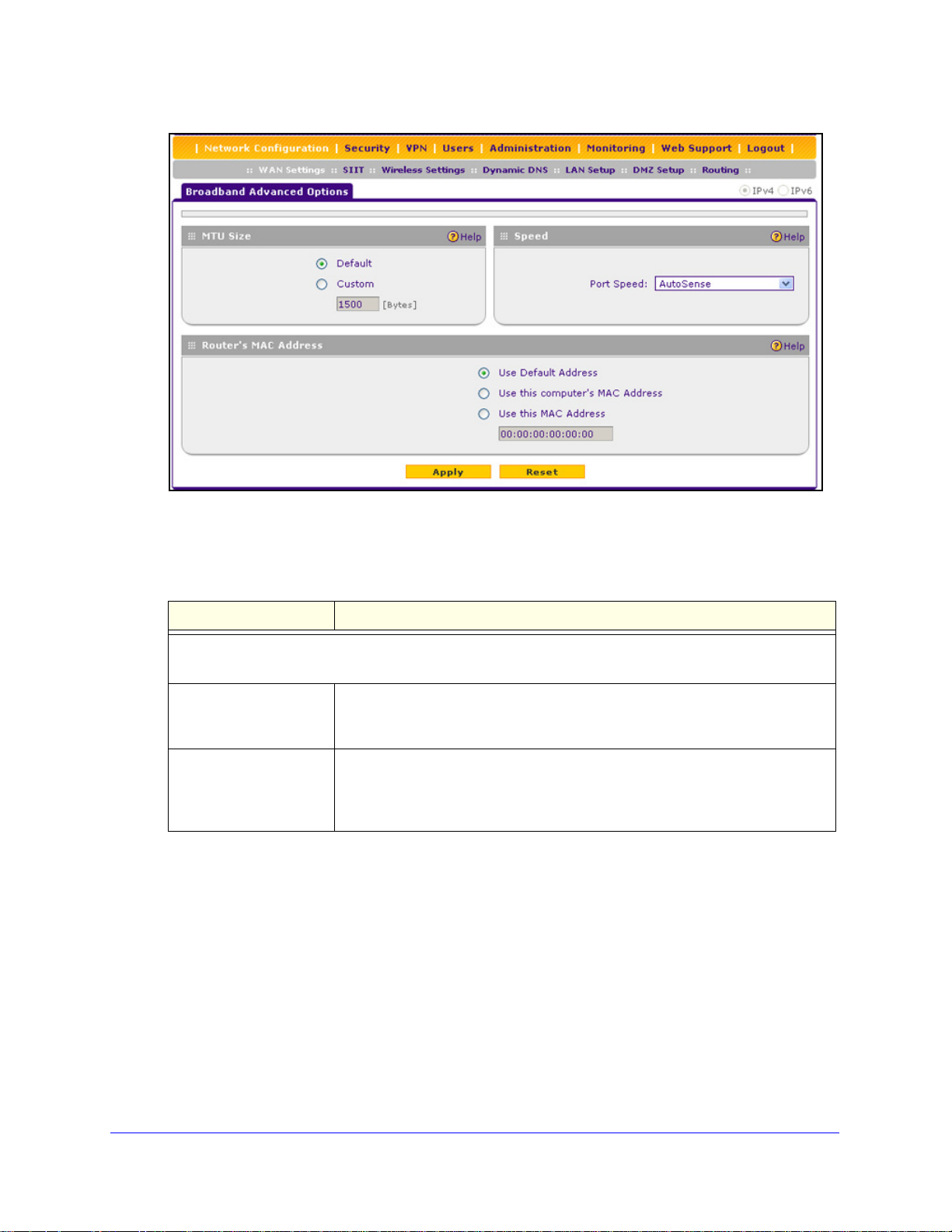
ProSafe Wireless-N 8-Port Gigabit VPN Firewall FVS318N
Figure 29.
3. Enter the settings as explained in the following table:
Table 10. Broadband Advanced Options screen settings
Setting Description
MTU Size
Make one of the following selections:
Default Select the Default radio button for the normal maximum transmit unit (MTU)
value. For most Ethernet networks, this value is 1500 bytes, or 1492 bytes for
PPPoE connections.
Custom Select the Custom radio button, and enter an MTU value in the Bytes field. For
some ISPs, you might need to reduce the MTU. This is rarely required, and
should not be done unless you are sure that it is necessary for your ISP
connection.
IPv4 and IPv6 Internet and Broadband Settings
51
Page 52

ProSafe Wireless-N 8-Port Gigabit VPN Firewall FVS318N
Table 10. Broadband Advanced Options screen settings (continued)
Setting Description
Speed
In most cases, the wireless VPN firewall can automatically determine the connection speed of the WAN
port of the device (modem, dish, or router) that provides the WAN connection. If you cannot establish an
Internet connection, you might need to manually select the port speed. If you know the Ethernet port speed
of the modem, dish, or router, select it from the drop-down list. Use the half-duplex settings only if the
full-duplex settings do not function correctly.
Select one of the following speeds from the drop-down list:
• AutoSense. S
duplex modes, including 1000BASE-T speed at full duplex.
BaseT Half_Duplex. Ethernet speed at half duplex.
• 10
BaseT Full_Duplex. Ethernet speed at full duple x.
• 10
• 100BaseT Half_Duplex. Fast Ethernet speed at half duplex.
0BaseT Full_Duplex. Fast Ethernet speed at full duplex.
• 10
00BaseT Half_Duplex. Gigabit Ethernet speed at half duplex.
• 10
• 1000BaseT Full_Duplex. Gigabit Ethernet spe ed at full duplex.
peed autosensing. This is the default setting, which can sense all Ethernet speeds and
Router’s MAC Address
ch computer or router on your network has a uni que 48-bit local Ethernet address. This is also referred to
Ea
as the computer’s Media Access Control (MAC) address. The default is set to Use Default Address.
Make one of the following selections:
Use Default Address Each computer or router on your network has a unique 32-bit local Ethernet
address. This is also referred to as the computer’s Media Access Control (MAC)
address. To use the wireless VPN firewall’s own MAC address, select the Use
Default Address radio button.
Use this computer’s MAC
Address
Use this MAC Address Select the Use this MAC Address radio button, and manually enter the MAC
Select the Use this computer’s MAC Address radio button to allow the
wireless VPN firewall to use the MAC address of the computer you are now
using to access the web management interface. This setting is useful if your ISP
requires MAC authentication.
address in the field next to the radio button. You would typically enter the MAC
address that your ISP is requiring for MAC authentication.
Note: The format for the MAC address is 01:23
0–9 and either uppercase or lowercase
address, the existing entry is overwritten.
letters A–F). If you enter a MAC
:45:67:89:AB (numbers
4. Click Apply to save your changes.
IPv4 and IPv6 Internet and Broadband Settings
52
Page 53

ProSafe Wireless-N 8-Port Gigabit VPN Firewall FVS318N
Additional WAN-Related Configuration Tasks
If you want the ability to manage the wireless VPN firewall remotely, enable remote
management (see Configure Remote Management Access on page 331). If you enable
remote management, NETGEAR strongly recommends that you change your password (see
Change Passwords and Administrator and Guest Settings on page 329).
You can set up the traffic meter for the WAN interface, if you wish. See Enable the WAN
Traffic Meter on page 346.
Verify the Connection
Test the wireless VPN firewall before deploying it in a live production environment. Verify that
network traffic can pass through the wireless VPN firewall:
• Ping an
• Ping the
Internet URL.
IP address of a device on either side of the wireless VPN firewall.
What to Do Next
You have completed setting up the WAN connection for the wireless VPN firewall. The
following chapters and sections describe important tasks that you need to address before
you deploy the wireless VPN firewall in your network:
• Chapter 3, LAN Configuration
• Chapter 4, Wireless Configuration and Security
• Configure Authentication Domains, Groups, and Users on
• Manage Digital Certificates for VPN Connections on p
• Use the IPSec VPN Wizard for Client and Gateway Configurations on p
• Chapter 7, Virtual Private Networking Using SSL Connections
page 296
age 313
age 194
IPv4 and IPv6 Internet and Broadband Settings
53
Page 54

3. LAN Configuration
This chapter describes how to configure the LAN features of your wireless VPN firewall. The
chapter contains the following sections:
• Manage IPv4 Virtual LANs and DHCP Options
• Configure IPv4 Multihome LAN IP Addresses on the Default VLAN
• Manage IPv4 Groups and Hosts (IPv4 LAN Groups)
• Manage the IPv6 LAN
• Configure IPv6 Multihome LAN IP Addresses on the Default VLAN
• Enable and Configure the DMZ Port for IPv4 and IPv6 Traffic
• Manage Static IPv4 Routing
• Manage Static IPv6 Routing
Manage IPv4 Virtual LANs and DHCP Options
3
• Port-Based VLANs
• Assign and Manage VLAN Profiles
• VLAN DHCP Options
• Configure a VLAN Profile
• Configure VLAN MAC Addresses and LAN Advanced Settings
A local area network (LAN) can generally be defined as a broadcast domain. Hubs, bridges,
or swit
Endpoints can communicate with each other without the need for a router. Routers connect
LANs together, routing the traffic to the appropriate port.
A virtual LAN (VLAN) is a local area network with a definition that maps workstations on
some basis other than geographic location (for example, by department, type of user, or
primary application). To enable traffic to flow between VLANs, traffic needs to go through a
router, as if the VLANs were on two separate LANs.
A VLAN is a group of computers, servers, and other network resources that behave as if they
were connected to a single network segment—even though they might not be. For example,
all marketing personnel might be spread throughout a building. Yet if they are all assigned to
a single VLAN, they can share resources and bandwidth as if they were connected to the
ches in the same physical segment or segments connect all end node devices.
54
Page 55

ProSafe Wireless-N 8-Port Gigabit VPN Firewall FVS318N
same segment. The resources of other departments can be invisible to the marketing VLAN
members, accessible to all, or accessible only to specified individuals, depending on how the
IT manager has set up the VLANs.
VLANs have a number of advantages:
• It is easy to set up network segmentation. Users who communicate most frequently with
each other can be grouped into common VLANs, regardless of physical location. Each
group’s traffic is contained largely within the VLAN, reducing extraneous traffic and
improving the efficiency of the whole network.
• They are easy to manage. The addition of nodes, as well as moves and other changes,
can be dealt with quickly and conveniently from a management interface rather than from
the wiring closet.
• T
hey provide increased performance. VLANs free up bandwidth by limiting node-to -node
and broadcast traffic throughout the network.
• T
hey ensure enhanced network security. VLANs create virtual boundaries that can be
crossed only through a router. So standard, router-based security measures can be used
to restrict access to each VLAN.
Port-Based VLANs
The wireless VPN firewall supports port-based VLANs. Port-based VLANs help to confine
broadcast traffic to the LAN ports. Even though a LAN port can be a member of more than
one VLAN, the port can have only one VLAN ID as its port VLAN identifier (PVID). By default,
all eight LAN ports of the wireless VPN firewall are assigned to the default VLAN, or VLAN 1.
Therefore, by default, all eight LAN ports have the default PVID 1. However, you can assign
another PVID to a LAN port by selecting a VLAN profile from the drop-down list on the LAN
Setup screen.
After you have created a VLAN profile and assigned one or more ports to the profile, you
need to enable the profile to activate it.
The wireless VPN firewall’s default VLAN cannot be deleted. All untagged traffic is routed
through the default VLAN (VLAN1), which you need to assign to at least one LAN port.
Note the following about VLANs and PVIDs:
• One p
• One p
• W
to another switch or router.
• W
the PVID.
hysical port is assigned to at least one VLAN.
hysical port can be assigned to multiple VLANs.
hen one port is assigned to multiple VLANs, the port is used as a trunk port to connect
hen a port receives an untagged packet, this packet is forwarded to a VLAN based on
• W
hen a port receives a tagged packet, this packet is forwarded to a VLAN based on the
ID that is extracted from the tagged packet.
LAN Configuration
55
Page 56

ProSafe Wireless-N 8-Port Gigabit VPN Firewall FVS318N
When you create a VLAN profile, assign LAN ports to the VLAN, and enable the VLAN, the
LAN ports that are members of the VLAN can send and receive both tagged and untagged
packets. Untagged packets that enter these LAN ports are assigned to the default PVID 1;
packets that leave these LAN ports with the same default PVID 1 are untagged. All other
packets are tagged according to the VLAN ID that you assigned to the VLAN when you
created the VLAN profile.
This is a typical scenario for a configuration with an IP phone that has two Ethernet ports, one
of which is connected to the wireless VPN firewall, the other one to another device:
Packets coming from the IP phone to the wireless VPN firewall LAN port are tagged. Packet s
passing through the IP phone from the connected device to the wireless VPN firewall LAN
port are untagged. When you assign the wireless VPN firewall LAN port to a VLAN, packets
entering and leaving the port are tagged with the VLAN ID. However, untagged packets
entering the wireless VPN firewall LAN port are forwarded to the default VLAN with PVID 1;
packets that leave the LAN port with the same default PVID 1 are untagged.
Note: The configuration of the DHCP options for the default VLAN is
explained in
Settings on
VLAN profile, including it
Configure the IPv4 Internet Connection and WAN
page 26. For information about how to add and edit a
s DHCP options, see Configure a VLAN
Profile on page 59.
Assign and Manage VLAN Profiles
To assign VLAN profiles to the LAN ports and manage VLAN profiles:
1. Select Network Configu
radio button is selected by default. The LAN submenu tabs display, with the LAN Setup
screen in view, displaying the IPv4 settings. (The following figure contains some VLAN
profiles as an example.)
ration > LAN Setup. In the upper right of the screen, the IPv4
LAN Configuration
56
Page 57

ProSafe Wireless-N 8-Port Gigabit VPN Firewall FVS318N
Figure 30.
For each VLAN profile, the following fields display in the VLAN Profiles table:
• Check box. Allows you to select the VLAN profile in the table.
• S
tatus icon. Indicates the status of the VLAN profile:
- Green c
- Gray circl
• Profile
• VLAN ID. The
• Sub
net IP. The subnet IP address for the VLAN profile.
• DHCP S
ircle. The VLAN profile is enabled.
e. The VLAN profile is disabled.
Name. The unique name assigned to the VLAN profile.
unique ID (or tag) assigned to the VLAN profile.
tatus. The DHCP server status for the VLAN profile, which can be either
DHCP Enabled or DHCP Disabled.
• Action. The
2. Assign a VLAN pro
Edit table button, which provides access to the Edit VLAN Profile screen.
file to a LAN port by selecting a VLAN profile from the drop-down list.
The enabled VLAN profiles are displayed in the drop-down lists.
3. Click App
ly to save your settings.
VLAN DHCP Options
For each VLAN, you need to specify the Dynamic Host Configuration Protocol (DHCP)
options (see Configure a VLAN Profile on page 59). The configuration of the DHCP options
for the wireless VPN firewall’s default VLAN, or VLAN 1, is explained in Configure the IPv4
Internet Connection and WAN Settings on page 26. This section provides further information
about the DHCP options.
LAN Configuration
57
Page 58

ProSafe Wireless-N 8-Port Gigabit VPN Firewall FVS318N
DHCP Server
The default VLAN (VLAN 1) has the DHCP server option enabled by default, allowing the
wireless VPN firewall to assign IP, DNS server , WINS server, and default gateway addresses
to all computers connected to the wireless VPN firewall’s LAN. The assigned default g ateway
address is the LAN address of the wireless VPN firewall. IP addresses are assigned to the
attached computers from a pool of addresses that you need to specify. Each pool address is
tested before it is assigned to avoid duplicate addresses on the LAN. When you create a new
VLAN, the DHCP server option is disabled by default.
For most applications, the default DHCP server and TCP/IP settings of the wireless VPN
firewall are satisfactory.
The wireless VPN firewall delivers the following settings to any LAN device that requests
DHCP:
• An IP add
• Subnet
• Ga
• Primary DNS server (th
• WINS server (if you entered a WINS server
• Lease time (th
teway IP address (the wireless VPN firewall’s LAN IP address)
ress from the range that you have defined
mask
e wireless VPN firewall’s LAN IP address)
address in the DHCP Setup screen)
e date obtained and the duration of the lease)
DHCP Relay
DHCP relay options allow you to make the wireless VPN firewall a DHCP relay agent for a
VLAN. The DHCP relay agent makes it possible for DHCP broadcast messages to be sent
over routers that do not support forwarding of these types of messages. The DHCP relay
agent is therefore the routing protocol that enables DHCP clients to obtain IP addresses from
a DHCP server on a remote subnet. If you do not configure a DHCP relay agent for a VLAN,
its clients can obtain IP addresses only from a DHCP server that is on the same subnet. To
enable clients to obtain IP addresses from a DHCP server on a remote subnet, you need to
configure the DHCP relay agent on the subnet that contains the remote clients, so that the
DHCP relay agent can relay DHCP broadcast messages to your DHCP server.
DNS Proxy
When the DNS proxy option is enabled for a VLAN, the wireless VPN firewall acts as a proxy
for all DNS requests and communicates with the ISP’s DNS servers (as configured on the
Broadband ISP Settings screens). All DHCP clients receive the primary and secondary DNS
IP addresses along with the IP address where the DNS proxy is located (that is, the wireless
VPN firewall’s LAN IP address). When the DNS proxy option is disabled for a VLAN, all
DHCP clients receive the DNS IP addresses of the ISP but without the DNS proxy IP
address.
LAN Configuration
58
Page 59

ProSafe Wireless-N 8-Port Gigabit VPN Firewall FVS318N
LDAP Server
A Lightweight Directory Access Protocol (LDAP) server allows a user to query and modify
directory services that run over TCP/IP. For example, clients can query email addresses,
contact information, and other service information using an LDAP server. For each VLAN,
you can specify an LDAP server and a search base that defines the location in the directory
(that is, the directory tree) from which the LDAP search begins.
Configure a VLAN Profile
For each VLAN on the wireless VPN firewall, you can configure its profile, port membership,
LAN TCP/IP settings, DHCP options, DNS server, and inter-VLAN routing capability.
To add a VLAN profile:
1. Select Ne
radio button is selected by default. The LAN submenu tabs display, with the LAN Setup
screen in view, displaying the IPv4 settings. (The following figure contains some VLAN
profiles as an example.)
Note: For information about how to manage VLANs, see Port-Based
twork Configuration > LAN Setup. In the upper right of the screen, the IPv4
VLANs on p
configure a VLAN profile.
age 55. The following information describes how to
Figure 31.
LAN Configuration
59
Page 60

ProSafe Wireless-N 8-Port Gigabit VPN Firewall FVS318N
2. Click the Add table button under the VLAN Profiles table. The Add VLAN Profile screen
displays:
Figure 32.
LAN Configuration
60
Page 61

ProSafe Wireless-N 8-Port Gigabit VPN Firewall FVS318N
3. Enter the settings as explained in the following table:
Table 11. Add VLAN Profile screen settings
Setting Description
VLAN Profile
Profile Name Enter a unique name for the VLAN profile.
VLAN ID Enter a unique ID number for the VLAN profile. No two VLANs can have the same
VLAN ID number.
Note: You can enter VLAN IDs from 2 to 4089. VLAN ID 1 is reserved for the
default VLAN; VLAN ID 4094 is reserved for the DMZ interface.
Port Membership
ort 1, Port 2, Port 3,
P
Port 4, Port 5, Port 6,
Port 7, and
Port 8 / DMZ
IP Setup
IP Address
Subnet Mask Enter the IP subnet mask. The subnet mask speci
DHCP
Select one, several, or all port check boxes to make the ports members of this
VLAN.
Note: A port that is defined as a member of a
data frames that are tagged with the VLAN ID.
Enter the IP address of the wireless VPN firewall (the factory default address is
192.168.1.1).
Note: Always make sure that the LAN port IP ad
are in different subnets.
Note: If you change the LAN IP address of
through the browser to the VLAN, you are disconnected. You then need to open
a new connection to the new IP address and log in again. For example, if you
change the default IP address 192.168.1.1 to 10.0.0.1, you now need to ente r
https://10.0.0.1 in your browser to reconnect to the web management interface.
of an IP address. Based on the IP address that you assign, the wireless VPN
firewall automatically calculates the subnet mask. Unless you are implementing
subnetting, use 255.255.255.0 as the subnet mask (computed by the wireless
VPN firewall).
VLAN profile can send and receive
the VLAN while being connected
dress and DMZ port IP address
fies the network number portion
Disable DHCP Server If another device on your network is the DHCP server for the VLAN, or if you will
manually configure the network settings of all of your computers, select the
Disable DHCP Server radio button to disable the DHCP server. Except for the
default VLAN for which the DHCP server is enabled, this is the default setting.
LAN Configuration
61
Page 62

ProSafe Wireless-N 8-Port Gigabit VPN Firewall FVS318N
Table 11. Add VLAN Profile screen settings (continued)
Setting Description
Enable DHCP Server Select the Enable DHCP Server radio button to enable the wireless VPN firewall
to function as a Dynamic Host Configuration Protocol (DHCP) server, providing
TCP/IP configuration for all computers connected to the VLAN. (For the default
VLAN, the DHCP server is enabled by default.) Enter the following settings:
Domain Name This setting is optional. Enter the domain name of the
wireless VPN firewall.
Start IP Address Enter the start IP address. This address specifies the first of
the contiguous addresses in the IP address pool. Any new
DHCP client joining the LAN is assigned an IP address
between this address and the end IP address. For the default
VLAN, the default start IP address is 192.168.1.100.
End IP Address Enter the end IP address. This address specifies the last of
the contiguous addresses in the IP address pool. Any new
DHCP client joining the LAN is assigned an IP address
between the start IP address and this IP address. For the
default VLAN, the default end IP address is 192.168.1.254.
The start and end DHCP IP addresses should be in the same
network as the LAN IP address of the wireless VPN firewall
(that is, the IP address in the IP Setup section as described
earlier in this table).
Primary DNS
Server
Secondary DNS
Server
WINS Server This setting is optional. Enter a WINS server IP address to
Lease Time Enter a lease time. This specifies the duration for which IP
DHCP Relay To use the wireless VPN firewall as a DHCP relay agent for a DHCP server
somewhere else in your network, select the DHCP Relay radio button. Enter the
following setting:
Relay Gateway The IP address of the DHCP server for which the wireless
This setting is optional. If an IP address is specified, the
wireless VPN firewall provides this address as the primary
DNS server IP address. If no address is specified, the
wireless VPN firewall uses the VLAN IP address as the
primary DNS server IP address.
This setting is optional. If an IP address is specified, the
wireless VPN firewall provides this address as the secondary
DNS server IP address.
specify the Windows NetBIOS server, if one is present in your
network.
addresses are leased to clients.
VPN firewall serves as a relay.
LAN Configuration
62
Page 63

ProSafe Wireless-N 8-Port Gigabit VPN Firewall FVS318N
Table 11. Add VLAN Profile screen settings (continued)
Setting Description
Enable LDAP
information
DNS Proxy
Enable DNS Proxy This setting is optional. To enable the wireless VPN firewall to provide a LAN IP
To enable the DHCP server to provide Lightweight Directory Access Protocol
(LDAP) server information, select the Enable LDAP information check box.
Enter the following settings.
LDAP Server The IP address or name of the LDAP server.
Search Base The search objects that specify the location in the directory
tree from which the LDAP search begins. You can specify
multiple search objects, separated by commas. The search
objects include:
• CN (for common name)
• OU (for organizational unit)
• O (for organization)
• C (for country)
• DC (for domain)
For example, to search the Netgea
names of Johnson, you would enter:
cn=Johnson,dc=Netgear,dc=net
Port The port number for the LDAP server. The default setting is 0
(zero).
address for DNS address name resolution, select the Enable DNS Proxy check
box. This setting is disabled by default.
r.net domain for all last
Note: When the DNS proxy option is disabled for a VLAN, all DHCP clients
ceive the DNS IP addresses of the ISP but without the DNS proxy IP address.
re
Inter VLAN Routing
Enable Inter VLAN
Routing
This setting is optional. To ensure that traffic is routed only to VLANs for which
inter-VLAN routing is enabled, select the Enable Inter VLAN Routing check box.
This setting is disabled by default. When the Enable Inter VLAN Routing check
box is not selected, traffic from this VLAN is not routed to other VLANs, and traffic
from other VLANs is not routed to this VLAN.
4. Click Apply to save your settings.
Note: Once you have completed the LAN setup, all outbound traffic is
allowed and all inbound traffic is discarded except responses to
requests from the LAN side. For information about how to change
these default traffic rules, see Chapter 5, Firewall Protection.
LAN Configuration
63
Page 64

ProSafe Wireless-N 8-Port Gigabit VPN Firewall FVS318N
To edit a VLAN profile:
1. On the LAN Setup screen for IPv4 (see Figure 31 on page 59), click the Edit button in
the Action column for the VLAN profile that you want to modify. The Edit VLAN Profile
screen displays. This screen is ide
ntical to the Add VLAN Profile screen (see the
previous figure).
2. Modif
3. Click Apply to save
To enable, disable, or delete one or more VLAN profiles:
1. On
y the settings as explained in the previous table.
your settings.
the LAN Setup screen for IPv4 (see Figure 31 on page 59), select the check box to
the left of each VLAN profile that you want to enable, disable, or delete, or click the
Select All
2. Click one
• Enable. Ena
table button to select all profiles. (You cannot select the default VLAN profile.)
of the following table buttons:
bles the VLAN or VLANs. The ! status icon changes from a gray circle to
a green circle, indicating that the selected VLAN or VLANs are enabled. (By default,
when a VLAN is added to the table, it is automatically enabled.)
• Disable. Disab
les the VLAN or VLANs. The ! status icon changes from a green circle
to a gray circle, indicating that the selected VLAN or VLANs are disabled.
• Delete. Deletes the VLAN or
VLANs.
Configure VLAN MAC Addresses and LAN Advanced Settings
By default, all configured VLAN profiles share the same single MAC address as the LAN
ports. (All LAN ports share the same MAC address.) However, you can change the VLAN
MAC settings to allow up to 16 VLANs to each be assigned a unique MAC address.
You can also enable or disable the broadcast of Address Resolution Protocol (ARP) packets
for the default VLAN. If the broadcast of ARP packets is enabled, IP addresses can be
mapped to physical addresses (that is, MAC addresses).
To configure a VLAN to have a unique MAC address:
1. Select Network Configu
ration > LAN Setup. In the upper right of the screen, the IPv4
radio button is selected by default. The LAN submenu tabs display, with the LAN Setup
screen in view, displaying the IPv4 settings (see Figure 31 on
2. Click the Advan
ced option arrow in the upper middle of the LAN Setup screen. The IPv4
page 59).
LAN Advanced screen displays:
LAN Configuration
64
Page 65

ProSafe Wireless-N 8-Port Gigabit VPN Firewall FVS318N
Figure 33.
3. From the MAC Address for VLANs drop-down list, select Unique. (The default is Same.)
4. As an option,
clearing the Enable ARP Broadcast check box. (The broadcast of ARP packets is enabled
by default for the default VLAN.)
5. Click App
you can disable the broadcast of ARP packets for the default VLAN by
ly to save your settings.
Note: If you attempt to configure more than 16 VLANs while the MAC
address for VLANs is set to Unique on the LAN Advanced screen,
the MAC addresses that are assigned to each VLAN might no longer
be distinct.
Configure IPv4 Multihome LAN IP Addresses on the Default VLAN
If you have computers using different IPv4 networks in the LAN (for example, 17 2.124.10.0 or
192.168.200.0), you can add aliases to the LAN ports and give computers on those networks
access to the Internet, but you can do so only for the default VLAN. The IP address that is
assigned as a secondary IP address needs to be unique and cannot be assigned to a VLAN.
Make sure that any secondary LAN addresses are different from the primary LAN, WAN, and
DMZ IP addresses and subnet addresses that are already configured on the wireless VPN
firewall. The following is an example of correctly configured IPv4 addresses:
AN IP address. 10.0.0.1 with subnet 255.0.0.0
• W
• DMZ IP add
• Primary LAN IP addre
ress. 176.16.2.1 with subnet 255.255.255.0
ss. 192.168.1.1 with subnet 255.255.255.0
• Second
ary LAN IP address. 192.168.20.1 with subnet 255.255.255.0
LAN Configuration
65
Page 66

ProSafe Wireless-N 8-Port Gigabit VPN Firewall FVS318N
To add a secondary LAN IPv4 address:
1. Select Network Configuration > LAN Setup > LAN Multi-homing. In the upper right of
the screen, the IPv4 radio button is selected by default. The LAN Multi-homing screen
displays the IPv4 settings. (The following figure contains one example.)
Figure 34.
The Available Secondary LAN IPs table displays the secondary LAN IP addre sses added
to the wireless VPN firewall.
the Add Secondary LAN IP Address section of the screen, enter the following settings:
2. In
• IP Address. Ent
• Subnet Mask.
3. Click the Add t
er the secondary address that you want to assign to the LAN ports.
Enter the subnet mask for the secondary IP address.
able button in the rightmost column to add the secondary IP address to the
Available Secondary LAN IPs table.
Repeat Step 2 and Step 3 for each secondary IP address that you want to add to the
Available Secondary LAN IPs table.
Note: Secondary IP addresses cannot be configured in the DHCP server.
The hosts on the secondary subnets need to be manua lly configured
with the IP addresses, gateway IP address, and DNS server IP
addresses.
To edit a secondary LAN IP address:
1. On
the LAN Multi-homing screen for IPv4 (see the previous figure), click the Edit button
in the Action column for the secondary IP address that you want to modify. The Edit LAN
Multi-homing screen displays.
2. Modif
3. Click Apply to save
y the IP address or subnet mask, or both.
your settings.
LAN Configuration
66
Page 67

ProSafe Wireless-N 8-Port Gigabit VPN Firewall FVS318N
To delete one or more secondary LAN IP addresses:
1. On the LAN Multi-homing screen for IPv4 (see the previous figure), select the check box
to the left of each secondary IP address that you want to delete, or click the Select All
table button to select secondary IP addresses.
2. Click the Del
ete table button.
Manage IPv4 Groups and Hosts (IPv4 LAN Groups)
• Manage the Network Database
• Change Group Names in the Network Database
• DHCPv6 Server Options
The Known PCs and Devices table on the LAN Groups (IPv4) screen (see Figure 3
page 68) contains a list of all known computers and network devices that are assigned
dynamic IP addresses by the wireless VPN firewall, have been discovered by other means,
or were entered manually. Collectively, these entries make up the network database.
The network database is updated by these methods:
• DHCP client
DHCP client requests from computers and other network devices. These requests also
generate an entry in the network database. This is an advantage of enabling the DHCP
server feature.
• Sca
nning the network. The local network is scanned using Address Resolution Protocol
(ARP) requests. The ARP scan detects active devices that are not DHCP clients.
Note: In large networks, scanning the network might generate unwanted
Note: When the wireless VPN firewall receives a reply to an ARP request,
requests. When the DHCP server is enabled, it accepts and responds to
traffic.
it might not be able to determine the device name if the software
firewall of the device blocks the name.
5 on
• Manual entry. You can manually enter information about a network device.
These are some advantages of the network database:
• Gene
• There is no need to reserve an IP address for a computer in the DHCP server
rally, you do not need to enter an IP address or a MAC address. Instead, you can
select the name of the desired computer or device.
address assignments made by the DHCP server are maintained until the computer or
device is removed from the network database, either by expiration (inactive for a long
time) or by you.
LAN Configuration
67
. All IP
Page 68

ProSafe Wireless-N 8-Port Gigabit VPN Firewall FVS318N
• There is no need to use a fixed IP address on a computer. Because the IP address
allocated by the DHCP server never changes, you do not need to assign a fixed IP
address to a computer to ensure that it always has the same IP address.
• A compute
r is identified by its MAC address—not its IP address. The network database
uses the MAC address to identify each computer or device. Therefore, changing a
computer’s IP address does not affect any restrictions applied to that computer.
• Control ove
ou can assign computers to groups (see Manage the Network Database on this
- Y
r computers can be assigned to groups and individuals:
page) and apply restrictions (outbound rules and inbound rules) to each group (see
Overview of Rules to Block or Allow Specific Kind
- Y
ou can select groups that are allowed access to URLs that you have blocked for
s of Traffic on page 129).
other groups, or the other way around, block access to URLs that you have allowed
access to for groups (see Configure Content Filtering on p
- If necessary
Enable Source MAC Filtering on p
identify each computer, users cannot avoid the
, you can also create firewall rules to apply to a single computer (see
age 183). Because the MAC address is used to
se restrictions by changing their IP
age 178).
address.
Manage the Network Database
You can view the network database, manually add or remove database entries, and edit
database entries.
To view the network database, select Network Configuration > LAN Setup > LAN Groups.
The LAN Groups screen displays. (The following figure shows some manually added devices
in the Known PCs and Devices table as an example.)
Figure 35.
LAN Configuration
68
Page 69

ProSafe Wireless-N 8-Port Gigabit VPN Firewall FVS318N
The Known PCs and Devices table lists the entries in the network database. For each
computer or device, the following fields display:
• Check box. Allows you to select the computer or device in the table.
• Name. The name of the computer or device. For computers that do not support the
NetBIOS protocol, the name is displayed as Unknown (you can edit the entry manually to
add a meaningful name). If the computer or device was assigned an IP address by the
DHCP server, then the name is appended by an asterisk.
• IP
Address. The current IP address of the computer or device. For DHCP clients of the
wireless VPN firewall, this IP address does not change. If a computer or device is
assigned a static IP address, you need to update this entry manua lly af te r the IP ad dress
on the computer or device has changed.
• M
AC Address. The MAC address of the computer or device’s network interface.
• Group. Each compu
ter or device can be assigned to a single LAN group. By default, a
computer or device is assigned to Group 1. You can select a different LAN group from the
Group drop-down list in the Add Known PCs and Devices section or on the Edit Groups
and Hosts screen.
• Profile
Name. Each computer or device can be assigned to a single VLAN. By default, a
computer or device is assigned to the default VLAN (VLAN 1). You can select a different
VLAN profile name from the Profile Name drop-down list in the Add Known PCs and
Devices section or on the Edit Groups and Hosts screen.
• Action. The
Edit table button, which provides access to the Edit Groups and Hosts
screen.
Add Computers or Devices to the Network Database
To add computers or devices manually to the network database:
1. I
n the Add Known PCs and Devices section of the LAN Groups screen (see the
previous figure), enter the settings as explained in the following table:
Table 12. Add Known PCs and Devices section settings
Setting Description
Name Enter the name of the computer or device.
IP Address Type From the drop-down list, select how the computer or device receives its IP address:
• Fixed (set on PC). The IP address is statically assigned on the computer or
device.
served (DHCP Client). The DHCP server of the wireless VPN firewall always
• Re
assigns the specified IP address to this client during the DHCP negotiation (see
also Set Up DHCP Add ress Reservation on p
Note: For both types of IP addresses, the wireless VPN firewall reserves the IP
dress for the associated MAC address.
ad
LAN Configuration
69
age 72).
Page 70

ProSafe Wireless-N 8-Port Gigabit VPN Firewall FVS318N
Table 12. Add Known PCs and Devices section settings (continued)
Setting Description
IP Address Enter the IP address that this computer or device is assigned to:
• If the IP address type is Fixed (set on PC), the IP address needs to be outside of
the address range that is allocated to the DHCP server pool to prevent the IP
address from also being allocated by th e DHCP server.
• If the IP address type is Reserved (DHCP Clie
outside the address range that is allocated to the D HCP server pool.
nt), the IP address can be inside or
Note: Make sure that the IP address is in the IP
you select from the Profile Name drop-down list.
MAC Address Enter the MAC address of the computer’s or device’s network interface. The MAC
address format is six colon-separated pairs of hexadecimal characters (0–9 and
a–f), such as 01:23:d2:6f:89:ab.
Group From the drop-down list, select the group to which the computer or device is
assigned. (Group 1 is the default group.)
Profile Name From the drop-down list, select the name of the VLAN profile to which the computer
or device is assigned.
subnet for the VLAN profile that
2. Click the Add table button to add the computer or device to the Known PCs and Devices
table.
3. As
an optional step: To save the binding between the IP address and MAC address for the
entry that you just added to the Known PCs and Devices table, select the check box for the
table entry, and click the Save Binding butt on.
Note: The saved binding is also displayed on the IP/MAC Binding screen
(see Figure 99 on page 186).
Edit Computers or Devices in the Network Database
To edit computers or devices manually in the network database:
1. In the Kno
wn PCs and Devices table of the LAN Groups screen (see the previous
figure), click the Edit table button of a table entry. The Edit LAN Groups screen displays
(see the following figure, which contains an example).
LAN Configuration
70
Page 71

ProSafe Wireless-N 8-Port Gigabit VPN Firewall FVS318N
Figure 36.
2. Modify the settings as explained in Table 12 on page 69.
3. Click App
ly to save your settings in the Known PCs and Devices table.
Deleting Computers or Devices from the Network Database
To delete one or more computers or devices from the network database:
1. On the
of each computer or device that you want
LAN Groups screen (see Figure 35 on page 68), select the check box to the left
to delete, or click the Select All table button
to select all computers and devices.
2. Click the Del
ete table button.
Note: If you delete a saved binding between an IP and MAC address on
the LAN Groups screen, make sure that you also delete the binding
on the IP/MAC Binding screen (see Figure 99 on page 186).
Change Group Names in the Network Database
By default, the groups are named Group1 through Group8. You can change these group
names to be more descriptive, such as GlobalMarketing and GlobalSales.
To edit the names of any of the eight available groups:
1. Select Ne
displays (see Figure 35 on
and Devices table).
twork Configuration > LAN Setup > LAN Groups. The LAN Groups screen
page 68, which shows some examples in the Known PCs
LAN Configuration
71
Page 72

ProSafe Wireless-N 8-Port Gigabit VPN Firewall FVS318N
2. Click the Edit Group Names option arrow to the right of the LAN submenu tabs. The
Network Database Group Names screen displays. (The following figure shows some
examples.)
Figure 37.
3. Select the radio button next to the group name that you want to edit.
4. T
ype a new name in the field. The maximum number of characters is 15. Do not use a
double quote (''), single quote('), or space in the name.
5. Repeat
6. Click Apply to save
Step 3 and Step 4 for any other group names.
your settings.
Set Up DHCP Address Reservation
When you specify a reserved IP address for a computer or device on the LAN (based on the
MAC address of the device), that computer or device always receives the same IP address
each time it accesses the wireless VPN firewall’s DHCP server. Reserved IP addresses
should be assigned to servers or access points that require permanent IP address settings.
The reserved IP address that you select needs to be outside of the DHCP server pool.
To reserve and bind an IP address to a MAC address, select Reserved (DHCP Client) from
the IP Address Type drop-down list on the LAN Groups screen and save the binding by
clicking the Save Binding button on the same screen. For det ailed steps, see Add Computers
or Devices to the Network Database on page 69.
Note: The reserved address is not assigned until the next time the
computer or device contacts the wireless VPN firewall’s DHCP
server. Reboot the comp uter or device, or access its IP configuration
and force a DHCP release and renew.
LAN Configuration
72
Page 73

ProSafe Wireless-N 8-Port Gigabit VPN Firewall FVS318N
Note: The saved binding is also displayed on the IP/MAC Binding screen
(see Figure 99 on page 186).
Manage the IPv6 LAN
• DHCPv6 Server Options
• Configure the IPv6 LAN
• Configure the IPv6 Router Advertisement Daemon and Advertisement Prefixes for the
LAN
An IPv6 LAN typically functions with site-local and link-local unicast addresses. Each
physical interface requires an IPv6 link-local address that is automatically derived from the
MAC addresses of the IPv4 interface and that is used for address configuration and neighbor
discovery. (Normally, you would not manually configure a link-local address.)
Traffic with site-local or link-local addresses is never forwarded by the wireless VPN firewall
(or by any other router), that is, the traffic remains in the LAN subnet and is processed over
the default VLAN only. A site-local address always starts with FEC0 (hexadecimal); a
link-local unicast address always starts with FE80 (hexadecimal). To forward traffic from
sources with a site local or link-local unicast address in the LAN, a DHCP server is required.
For more information about link-local unicast addresses, see Configure ISATAP Automatic
Tunneling on page 47.
Because each interface is automatically assigned a link-local IP address, it is not useful to
assign another link-local IP address as the default IPv6 LAN address. The default IPv6 LAN
address is a site-local address. You can change this address to any other IPv6 address for
LAN use.
Note: Site-local addresses, that is, addresses that start with FEC0, have
been depreciated. However, NETGEAR has implemented a
site-local address as a temporary default IPv6 LAN address that you
can replace with another LAN address. The firewall restricts external
communication of this default site-local address.
DHCPv6 Server Options
The IPv6 clients in the LAN can autoconfigure their own IPv6 address or obtain an IPv6
address through a DHCPv6 server. For the LAN, there are three DHCPv6 options:
Stateless DHCPv6 Server
The IPv6 clients in the LAN generate their own IP address by using a combination of locally
available information and router advertisements, but receive DNS server informatio n from the
LAN Configuration
73
Page 74

ProSafe Wireless-N 8-Port Gigabit VPN Firewall FVS318N
DHCPv6 server. For stateless DHCPv6, you need to configure the RADVD and
advertisement prefixes (see Configure the IPv6 Router Advertisement Daemon and
Advertisement Prefixes for the LAN on page 80).
Stateless DHCPv6 Server With Prefix Delegation
As an option for a stateless DHCPv6 server, you can enable prefix delegation. The ISP’s
stateful DHCPv6 server assigns a prefix that is used by the wireless VPN firewall’s stateless
DHCPv6 server to assign to its IPv6 LAN clients.
Prefix delegation functions in the following way:
1. The wire
less VPN firewall’s DHCPv6 client requests prefix delegation from the ISP.
You need to select the Prefix Delegation check box on the ISP Broadband Settings
screen fo
r IPv6 (see Use a DHCPv6 Server to Configure an IPv6 Internet Connection on
page 39).
2. Th
e ISP allocates a prefix to the wire l es s V PN fi re w al l .
This prefix is automatically added to the List of Prefixes to Advertise table on the LAN
DVD screen for IPv6 (see Configure the IPv6 Router Advertisement Daemon and
RA
Advertisement Prefixes for the LAN on
3. Th
e stateless DHCPv6 server allocates the prefix to the IPv6 LAN clients through the
page 80).
RADVD. When prefix delegation is enabled, the RADVD advertises the following prefixes:
• The p
• Prefixes that
refix that was added through prefix delegation.
you manually added to the List of Prefixes to Advertise table on the
RADVD screen.
You need to perform the following tasks:
• Select the
Configure the IPv6 LAN on
• Config
Advertisement Prefixes for the LAN on
• Op
tionally, manually add prefixes to the List of Prefixes for Prefix Delegation table on
Prefix Delegation check box on the LAN Setup screen for IPv6 (see
page 75).
ure the RADVD (see Configure the IPv6 Router Advertisement Daemon and
page 80).
the LAN Setup screen for IPv6 (see IPv6 LAN Prefixes for Prefix Delegation on
page 79).
• Op
tionally, manually add prefixes to List of Prefixes to Advertise table on the RADVD
screen (see Advertisement Prefixes for the LAN on p
age 82).
Stateful DHCPv6 Server
The IPv6 clients in the LAN obtain an interface IP address, configuration information such as
DNS server information, and other parameters from the DHCPv6 server. The IP address is a
dynamic address. For stateful DHCPv6, you need to configure IPv6 address pools (see IPv6
LAN Address Pools on page 77).
LAN Configuration
74
Page 75

ProSafe Wireless-N 8-Port Gigabit VPN Firewall FVS318N
Configure the IPv6 LAN
To configure the IPv6 LAN settings:
1. Select Network Configuratio
2. In the uppe
r right of the screen, select the IPv6 radio button. The LAN Setup screen displays
n > LAN Setup.
the IPv6 settings. (The following figure contains some examples.)
Figure 38.
LAN Configuration
75
Page 76

ProSafe Wireless-N 8-Port Gigabit VPN Firewall FVS318N
3. Enter the settings as explained in the following table. The IPv6 address pools and prefixes
for prefix delegation are explained in the sections following the table.
Table 13. LAN Setup screen settings for IPv6
Setting Description
IPv6 LAN Setup
IPv6 Address Enter the LAN IPv6 address. The default address is FEC0::1.(For more information,
see the introduction to this section, Manage the IPv6 LAN.)
IPv6 Prefix Length Enter the IPv6 prefix length, for example, 10 or 64. The default prefix length is 64.
DHCPv6
DHCP Status Specify the status of the DHCPv6 server:
• Disable DHCPv6 Server. This is the default setting, and the DHCPv6 fiel ds are
masked out.
able the DHCPv6 Server. If you enable the server, you need to complete the
• En
DHCPv6 fields.
DHCP Mode Select one of the DHCPv6
tateless. The IPv6 clients generate their own IP address by
• S
using a combination of locally available information and router
advertisements, but receive DNS server information from the
DHCPv6 server. For stateless DHCPv6, you need to configure
the RADVD and advertisement prefixes (see Configure the
IPv6 Router Advertisement Daemon and Advertisement
Prefixes for the LAN on p
enable prefix delegation (see the explan ation further down in
this table).
ateful. The IPv6 clients obtain an interface IP address,
• St
configuration information such as DNS server information, and
other parameters from the DHCPv6 server. The IP address is a
dynamic address. You need to add IPv6 address pools to the
List of IPv6 Address Pools table on the LAN Setup screen (see
IPv6 LAN Address Pools o
Prefix Delegation If you have selected the st
the Prefix Delegation check box:
fix delegation check box is selected. The stateless
• Pre
DHCPv6 server assigns prefixes to its IPv6 LAN clients. Make
sure that the Prefix Delegation check box on the ISP
Broadband Settings screen for IPv6 is also selected (see Use
a DHCPv6 Server to Configure an IPv6 Internet Connection on
page 39) to enable the wireless VPN firewall to acquire a prefix
from the ISP through prefix delegatio
prefix is automatically added to the List of Prefixes to Advertise
table on the LAN RADVD screen for IPv6 (see Configure the
IPv6 Router Advertisement Daemon and Advertisement
Prefixes for the LAN on p
• Prefix delegation check b ox is cleared. Prefix delegation is
disabled in the LAN. This is the default setting.
modes from the drop-down list:
age 80). As an option, you can
n page 77).
ateless DHCPv6 mode, you can select
n. In this configuration, a
age 80).
Domain Name Enter the domain name of th e DHCP server.
LAN Configuration
76
Page 77

ProSafe Wireless-N 8-Port Gigabit VPN Firewall FVS318N
Table 13. LAN Setup screen settings for IPv6 (continued)
Setting Description
DHCP Status
(continued)
Server Preference Enter the DHCP server preference value. The possible values
are 0–255, with 255 as the default setting.
This is an optional setting that specifies the server’s preference
value in a server advertise message. The client selects the
server with the highest preference value as the preferred server.
DNS Servers Select one of the DNS server options from the drop-down lists:
• Use DNS
all DNS requests and communicates with the ISP’s DNS
servers that you configured on the Broadband ISP Settings
(IPv6) screen (see Configure a Static IPv6 Internet Connection
on page 41).
• Use
DNS servers that you configured on the Broadband ISP
Settings (IPv6) screen (see Configure a Static IPv6 Internet
Connection on p
• Use
become available for you to enter IP addresses.
Primary DNS Server Enter the IP address of the primary
Secondary DNS Server Enter the IP address of the secondary
Lease/Rebind Time Enter the period after which the DHCP lease is renewed with the
original DHCP server or rebound with another DHCP server to
extend the existing DHCP lease. The default period is
86400 seconds (24 hours).
Proxy. The wireless VPN firewall acts as a proxy for
DNS from ISP. The wireless VPN firewall uses the ISP’s
age 41).
below. When you select this option, the DNS server fields
DNS server for the LAN.
DNS server for the LAN.
4. Click Apply to save your changes.
IPv6 LAN Address Pools
If you configure a stateful DHCPv6 server for the LAN, you need to add local DHCP IPv6
address pools so the DHCPv6 server can control the allocation of IPv6 addresses in the LAN.
To add an IPv6 LAN address pool:
1. On the
Add. The LAN IPv6 Config screen displays:
LAN Setup screen for IPv6, under the List of IPv6 Address Pools table, click
LAN Configuration
77
Page 78

ProSafe Wireless-N 8-Port Gigabit VPN Firewall FVS318N
Figure 39.
2. Enter the settings as explained in the following table:
Table 14. LAN IPv6 Config screen settings
Setting Description
Start IPv6 Address Enter the start IP address. This address specifies the first of the contiguous
addresses in the IP address pool. Any new DHCPv6 client joining the LAN is
assigned an IP address between this address and the end IP address.
End IPv6 Address Enter the end IP address. T his address specifies the last of the contiguous
addresses in the IP address pool. Any new DHCPv6 client joining the LAN is
assigned an IP address between the start IP address and this IP address.
Prefix Length Enter the IPv6 prefix length, for example, 10 or 64.
3. Click Apply to
save your changes and add the new IPv6 address pool to the L i s t o f IP v 6
Address Pools table on the LAN Setup screen for IPv6.
To edit an IPv6 LAN address pool:
1. On
the LAN Setup screen for IPv6 (see Figure 38 on page 75), click the Edit button in
the Action column for the address pool that you want t
screen displays.
2. Modif
3. Click Apply to save
To delete one or more IPv6 LAN address pools:
1. On
y the settings as explained in the previous table.
your settings.
the LAN Setup screen for IPv6 (see Figure 38 on page 75), select the check box to
the left of each address pool that you want to delete, or click the Select
to select all address pools.
o modify. The LAN IPv6 Config
All table button
2. Click the Delete t
able button.
LAN Configuration
78
Page 79

ProSafe Wireless-N 8-Port Gigabit VPN Firewall FVS318N
IPv6 LAN Prefixes for Prefix Delegation
If you configure a stateless DHCPv6 server for the LAN and select the Prefix Delegation
check box (both on the ISP Broadband Settings screen for IPv6 and on the LAN Setup
screen for IPv6, a prefix delegation pool is automatically added to the List of Prefixes for
Prefix Delegation table. You can also manually add prefixes to the List of Prefixes for Prefix
Delegation table to enable the DHCPv6 server to assign these prefixes to its IPv6 LAN
clients.
To add an IPv6 prefix:
1. On the LAN Setup screen
click Add. The Add Prefix Delegation Prefixes screen displays:
Figure 40.
2. Enter the following settings:
• IP
v6 Prefix. Enter a prefix, for example, 2001:db8::.
• I
Pv6 Prefix Length. Enter the IPv6 prefix length, for example, 64.
3. Click App
ly to save your changes and add the new prefix to the Lis t o f Pr e fi x es fo r P re fi x
Delegation table on the LAN Setup screen for IPv6.
To edit a prefix:
for IPv6, under the List of Prefixes for Prefix Delegation table,
1. On the
LAN Setup screen for IPv6 (see Figure 38 on page 75), click the Edit button in
the Action column for the prefix that you want to modify. The Edit Prefix Delegation
fixes screen displays.
Pre
2. Mo
3. Click App
To delete one or more prefixes:
1. On the LAN Setup screen
dify the settings as explained in Step 2 of the previous procedure.
ly to save your settings.
for IPv6 (see Figure 38 on page 75), select the check box to
the left of each prefix that you want to delete, or click the Se
select all prefixes.
2. Click the Del
ete table button.
lect All table button to
LAN Configuration
79
Page 80

ProSafe Wireless-N 8-Port Gigabit VPN Firewall FVS318N
Configure the IPv6 Router Advertisement Daemon and Advertisement Prefixes for the LAN
Note: If you do not configure stateful DHCPv6 for the LAN but use
stateless DHCPv6, you need to configure the Router Advertisement
Deamon (RADVD) and advertisement prefixes.
The RADVD is an application that uses the Neighbor Discovery Protocol (NDP) to collect
link-local advertisements of IPv6 addresses and IPv6 prefixes in the LAN. The RADVD then
distributes this information in the LAN, which allows IPv6 clients to configure their own IPv6
address.
Hosts and routers in the LAN use NDP to determine the link-layer addresses and related
information of neighbors in the LAN that can forward packets on their behalf. The wireless
VPN firewall periodically distributes router advertisements (RAs) throughout the LAN to
provide such information to the hosts and routers in the LAN. RAs include IPv6 addresses,
types of prefixes, prefix addresses, prefix lifetimes, the maximum transmission unit (MTU),
and so on. In addition to configuring the RADVD, you also need to configure the prefixes th at
are advertised in the LAN RAs.
The following table provides an overview of how information is obtained in the LAN when you
have configured a stateless DHCPv6 server and the RADVD:
Table 15. DHCPv6 and RADVD interaction in the LAN
Flags in the RADVD DHCPv6 Server Provides RADVD Provides
Managed RA flag is set • IP address assignment
• DNS server and other configuration information
Other RA flag is set DNS server and other configuration information • IP address assignment
• IP address assignment
• Prefix
• Prefix length
• Gateway address
• Prefix
• Prefix length
• Gateway address
When the Managed flag is set in the RADVD, the DHCPv6 server can assign IP addresses,
and the RADVD also assigns IP addresses in the sense that it provides information that
allows IPv6 clients to configure their own IPv6 address.
When the Other flag is set, the DHCPv6 server does not assign IP addresses but provides
DNS server and other configuration information only.
LAN Configuration
80
Page 81

ProSafe Wireless-N 8-Port Gigabit VPN Firewall FVS318N
To configure the Router Advertisement Daemon for the LAN:
1. Select Network Configuration > LAN Setup.
2. In the uppe
the IPv6 settings (see Figure 38 on p
3. T
o the right of the LAN Setup tab, click the RADVD option arrow. The RADVD screen for the
r right of the screen, select the IPv6 radio button. The LAN Setup screen displays
age 75.)
LAN displays. (The following figure contains some examples.)
Figure 41.
4. Enter the settings as explained in the following table:
Table 16. RADVD screen settings for the LAN
Setting Description
RADVD Status Specify the RADVD status by making a selection from the drop-down list:
• Enable. The RADVD is enabled, and the RADVD fields become available for you to
configure.
able. The RADVD is disabled, and the RADVD fields are masked out. This is the
• Dis
default setting.
Advertise Mode Specify the advertisement mode by
solicited Multicast. The wireless VPN firewall advertises unsolicited multicast
• Un
packets at a rate that is specified by the advertisement interval.
nicast only. The wireless VPN firewall responds to unica st packet requests only.
• U
No unsolicited packets are advertised. Select this option for nonbroadcast multiple
access (NBMA) links such as ISATAP.
LAN Configuration
81
making a selection from the drop-down list:
Page 82

ProSafe Wireless-N 8-Port Gigabit VPN Firewall FVS318N
Table 16. RADVD screen settings for the LAN (continued)
Setting Description
Advertise Interval Enter the advertisement interval of unsolicited multicast packets in seconds. The
minimum value is 10 seconds; the maximum value is 1800 seconds.
RA Flags Specify what type of information the DHCPv6 server provides in the LAN by making a
selection from the drop-down list:
• Managed.
• Other. The DHCPv6 server is not used for autoconfiguration of the IP address, but
other configuration information such as DNS information is available through the
DHCPv6 server.
Note: Irrespective of the RA flag settings, the RADVD provides information about the
fix, prefix length, and gateway addresses and is also used for autoconfiguration of
pre
the IP address.
The DHCPv6 server is used for autoconfiguration of the IP address.
Router Preference Specify the wireless VPN firewall’s preferen
the LAN by making a selection from the drop-down list:
w. The wireless VPN firewall is treated as a nonpreferred router in the LAN.
• Lo
• Medium. The wireless VPN firewall is treated as a neutral router in the LAN.
• High. Th
MTU The maximum transmission unit (MTU) size fo r a packet in one transmission over a
link. The default setting is 1500.
Router Lifetime The router lifetime specifies how long the default route that was created as a result of
the router advertisement should remain valid.
Enter the router lifetime in seconds. This is the period that the advertised prefixes are
valid for route determination. The default period is 3600 seconds (one hour). The
minimum value is 30 seconds; the maximum value is 9000 seconds.
e wireless VPN firewall is treated as a preferred router in the LAN.
ce in relation to other hosts and routers in
5. Click Apply to save your changes.
Advertisement Prefixes for the LAN
You need to configure the prefixes that are advertised in the LAN RAs. For a 6to4 address,
you need to specify only the site level aggregation identifier (SLA ID) and the prefix lifetime.
For a global, local, or ISA TAP address, you need to specify the prefix, prefix length, and prefix
lifetime.
To add an advertisement prefix for the LAN:
1. On
the RADVD screen for the LAN, under the List of Prefixes to Advertise table, click
Add. The Add Advertisement Prefix screen displays:
LAN Configuration
82
Page 83

ProSafe Wireless-N 8-Port Gigabit VPN Firewall FVS318N
Figure 42.
2. Enter the settings as explained in the following table:
Table 17. Add Advertisement Prefix screen settings for the LAN
Setting Description
IPv6 Prefix Type Specify the IPv6 prefix type by making a selection from the drop-down list:
• 6to4. The prefix is for a 6to4 address. You need to complete the SLA ID field and
Prefix Lifetime field. The other fields are maske d out.
al/Local/ISATAP. The prefix is for a global, local, or ISATAP address. This
• Glob
needs to be a global prefix or a site-local prefix; it cannot be a link-local prefix. You
need to complete the IPv6 Prefix field, IPv6 Prefix Length field, and Prefix Lifetime
field. The SLA ID field is masked out.
SLA ID Enter the site level aggregation identifier
should be included in the advertisement.
IPv6 Prefix Enter the IPv6 prefix for the wireless VPN firewall’s LAN that should be included in the
advertisement.
IPv6 Prefix Length Enter the IPv6 prefix length (typically 64) that should be included in the advertisement.
Prefix Lifetime The prefix lifetime specifies how long the IP address that was created as a result of the
router advertisement should remain valid.
Enter the prefix lifetime in seconds that should be included in the advertisement. The
minimum period is 0 seconds; the maximum period is 65536 seconds.
3. Click App
ly to save your changes and add the new IPv6 address pool to the Lis t o f
Prefixes to Advertise table on the RADVD screen for the LAN.
To edit an advertisement prefix:
(SLA ID) for the 6to4 address prefix that
1. On the
RADVD screen for the LAN (see Figure 41 on page 81), click the Edit button in
the Action column for the advertisement prefix that you want to modify. The Add
Advertisement Prefix screen d
2. Mo
3. Click App
dify the settings as explained in the previous table.
ly to save your settings.
isplays.
LAN Configuration
83
Page 84

ProSafe Wireless-N 8-Port Gigabit VPN Firewall FVS318N
To delete one or more advertisement prefixes:
1. On the RADVD screen for the LAN (see Figure 41 on page 81), select the check box to
the left of each advertisement prefix that you want to delete, or click the Select All t
button to select all advertisement prefixes.
able
2. Click the Delete t
able button.
Configure IPv6 Multihome LAN IP Addresses on the Default VLAN
If you have computers using different IPv6 networks in the LAN (for example, FEC0::2 or
FEC0::1000:10), you can add aliases to the LAN ports and give computers on those networks
access to the Internet, but you can do so only for the default VLAN.
The IP address that is assigned as a secondary IP address needs to be unique and cannot
be assigned to a VLAN.
Make sure that any secondary LAN addresses are different from the primary LAN, W AN, and
DMZ IP addresses and subnet addresses that are already configured on the wireless VPN
firewall. The following is an example of correctly configured IPv6 addresses:
AN IP address. 2000::e246:9aff:fe1d:1a9c with a prefix length of 64
• W
• DMZ IP a
• Primary LAN IP ad
• Seco
ddress. 176::e246:9aff:fe1d:a1bc with a prefix length of 64
dress. FEC0::1 with a prefix length of 10
ndary LAN IP address. 2001:db8:3000::2192 with a prefix length of 10.
To add a secondary LAN IPv6 address:
1. Select Netwo
the upper right of the screen, select the IPv6 radio button. The LAN Multi-homing screen
2. In
displays the IPv6 settings. (The following figure contains one example.)
Figure 43.
rk Configuration > LAN Setup > LAN Multi-homing.
LAN Configuration
84
Page 85

ProSafe Wireless-N 8-Port Gigabit VPN Firewall FVS318N
The Available Secondary LAN IPs table displays the secondary LAN IP addresses adde d
to the wireless VPN firewall.
3. In the Add
• I
• Prefix
4. Click the Ad
Available Secondary LAN IPs table.
Repeat Step 2 and Step 3 for each secondary IP address that you want to add to the
Available Secondary LAN IPs table.
Note: Secondary IP addresses cannot be configured in the DHCP server.
To edit a secondary LAN IP address:
1. On the
in the Action column for the secondary IP address that you want to modify. The Edit
LAN Multi-homing screen displays.
2. Mo
3. Click App
dify the IP address or prefix length, or both.
Secondary LAN IP Address section of the screen, enter the following settings:
Pv6 Address. Enter the secondary address that you want to assign to the LAN port s.
Length. Enter the prefix length for the secondary IP address.
d table button in the rightmost column to add the secondary IP address to the
The hosts on the secondary subnets need to be manually configured
with the IP addresses, gateway IP address, and DNS server IP
addresses.
LAN Multi-homing screen for IPv6 (see the previous figure), click the Edit button
ly to save your settings.
To delete one or more secondary LAN IP addresses:
1. On th
2. Click the Del
e LAN Multi-homing screen for IPv6 (see the previous figure), select the check box
to the left of each secondary IP address that you want to delete, or click the Select All
table button to select secondary IP addresses.
ete table button.
Enable and Configure the DMZ Port for IPv4 and IPv6 Traffic
• DMZ Port for IPv4 Traffic
• DMZ Port for IPv6 Traffic
• Configure the IPv6 Router Advertisement Daemon and Advertisement Prefixes for the
DMZ
The demilitarized zone (DMZ) is a network that, by defa
the LAN. The DMZ can be used to host servers (such as a web server, FTP server, or email
server) and provide public access to them. The rightmost LAN port on the wireless VPN
ult, has fewer firewall restrictions than
LAN Configuration
85
Page 86

ProSafe Wireless-N 8-Port Gigabit VPN Firewall FVS318N
firewall can be dedicated as a hardware DMZ port to safely provide services to the Internet
without compromising security on your LAN.
By default, the DMZ port and both inbound and outbound DMZ traffic are disabled. Enabling
the DMZ port and allowing traffic to and from the DMZ increases the traffic through the WAN
ports.
Using a DMZ port is also helpful with online games and videoconferencing applications that
are incompatible with NAT. The wireless VPN firewall is programmed to recognize some of
these applications and to work correctly with them, but there are other applications that might
not function well. In some cases, local computers can run the application correctly if those
computers are used on the DMZ port.
Note: A separate firewall security profile is provided for the DMZ port that
is also physically independent of the standard firewall security
component that is used for the LAN.
Note: For information about how to define the DMZ WAN rules and LAN
DMZ rules, see
Configure DMZ WAN Rules on page 145 and
Configure LAN DMZ Rules on page 153, respectively.
Note: When you enable the DMZ port for IPv4 traffic, IPv6 traffic, or both,
the DMZ LED next to LAN port 8 (see
Front Panel on page 15) lights
green to indicate that the DMZ port is enabled.
DMZ Port for IPv4 Traffic
The DMZ Setup (IPv4) screen lets you set up the DMZ po rt for IPv4 traf fic. You can enable or
disable the hardware DMZ port (LAN port 8; see Front Panel on page 15) and configure an
IPv4 address and subnet mask for the DMZ port.
To enable and configure the DMZ port for IPv4 traffic:
1. Select Ne
radio button is selected by default. The DMZ Setup screen displays the IPv4 settings:
twork Configuration > DMZ Setup. In the upper right of the screen, the IPv4
LAN Configuration
86
Page 87

ProSafe Wireless-N 8-Port Gigabit VPN Firewall FVS318N
Figure 44.
2. Enter the settings as explained in the following table:
Table 18. DMZ Setup screen settings for IPv4
Setting Description
DMZ Port Setup
Do you want to
enable DMZ Port?
Select one of the following radio buttons:
• Yes. En ables you to configure the DMZ port settings. Fill i n the IP Address and
Subnet Mask fields.
• No. Allow
IP Address Enter the IP address of the DMZ port. Make su
s you to disable the DMZ port after you have configured it.
port IP address and LAN port IP address are in different
subnets (for example, an address outside the LAN DHCP
address pool, such as 192.168.1.101 when the LAN DHCP
pool is 192.168.1.2–192.168.1.100). The default IP address for
the DMZ port 176.16.2.1.
LAN Configuration
87
re that the DMZ
Page 88

ProSafe Wireless-N 8-Port Gigabit VPN Firewall FVS318N
Table 18. DMZ Setup screen settings for IPv4 (continued)
Setting Description
Do you want to
enable DMZ Port?
(continued)
DHCP for DMZ Connected Computers
Disable DHCP Server If another device on your network is the DHCP server for the VLAN, or if you will
Enable DHCP Server Select the Enable DHCP Server radio button to enable the wireless VPN firewall to
Subnet Mask Enter the IP subnet mask of the DMZ port. The subnet mask
specifies the network number portion of an IP address. The
subnet mask for the DMZ port is 255.255.255.0.
manually configure the network set tings of a ll of your computers, se lect the Disable
DHCP Server radio button to disable the DHCP server. This is the default setting.
function as a Dynamic Host Configuration Protocol (DHCP) server, providing
TCP/IP configuration for all computers connected to the VLAN. Enter the following
settings:
Domain Name This setting is optional. Enter the domain name of the wireless
VPN firewall.
Start IP Address Enter the start IP address. This address specifies the first of
the contiguous addresses in the IP address pool. Any new
DHCP client joining the LAN is assigned an IP address
between this address and the end IP address. The default IP
address 176.16.2.100.
End IP Address Enter the end IP address. This address specifies the last of the
contiguous addresses in the IP address pool. Any new DHCP
client joining the LAN is assigned an IP address between the
start IP address and this IP address. The default IP address
176.16.2.254.
Note: The start and end DHCP IP addresses should be in the
same network as the LAN TCP/IP address of the wireless VPN
firewall (that is, the IP address in the DMZ Port Setup section
as described earlier in this table).
Primary DNS
Server
Secondary DNS
Server
WINS Server This setting is optional. Enter a WINS server IP address to
Lease Time Enter a lease time. This specifies the duration for which IP
This setting is optional. If an IP address is specified, the
wireless VPN firewall provides this address as the primary
DNS server IP address. If no address is specified, the wireless
VPN firewall provides its own LAN IP address as the primary
DNS server IP address.
This setting is optional. If an IP address is specified, the
wireless VPN firewall provides this address as the secondary
DNS server IP address.
specify the Windows NetBIOS server, if one is present in your
network.
addresses are leased to clients.
LAN Configuration
88
Page 89
ProSafe Wireless-N 8-Port Gigabit VPN Firewall FVS318N
Table 18. DMZ Setup screen settings for IPv4 (continued)
Setting Description
DHCP Relay To use the wireless VPN firewall as a DHCP relay agent for a DHCP server
somewhere else in your network, select the DHCP Relay radio button. Enter the
following setting:
Relay Gateway The IP address of the DHCP server for which the wireless VPN
firewall serves as a relay.
Enable LDAP
information
DNS Proxy
Enable DNS Proxy This setting is optional. To enable the wireless VPN firewall to provide a LAN IP
To enable the DHCP server to provide Lightweight Directory Access Protocol
(LDAP) server information, select the Enable LDAP information check box. Enter
the following settings.
LDAP Server The IP ad dress or name of the LDAP server.
Search Base The search objects that specify the location in the directory tree
from which the LDAP search begins. You can specify multiple
search objects, separated by commas. The search objects
include:
• CN (for common name)
• OU (for organizational unit)
• O (for organization)
• C (for country)
• DC (for domain)
For example, to search the Netgear.net domain for all last
mes of Johnson, you would enter:
na
cn=Johnson,dc=Netgear,dc=net
Port The port number for the LDAP server. The default setting is 0
(zero).
address for DNS address name resolution, select the Enable DNS Proxy check
box. This check box is selected by default.
Note: When the DNS Proxy option is disabled,
IP addresses of the ISP but without the DNS proxy IP address.
all DHCP clients receive the DNS
3. Click Apply to save your settings.
DMZ Port for IPv6 Traffic
The DMZ Setup (IPv6) screen lets you set up the DMZ port for IPv6 traffic. You can enable or
disable the hardware DMZ port (LAN port 8; see Front Panel on p a ge 15) for IPv6 traffic and
configure an IPv6 address and prefix length for the DMZ port.
The IPv6 clients in the DMZ can autoconfigure their own IPv6 address or obtain an IPv6
address through a DHCPv6 server.
LAN Configuration
89
Page 90

ProSafe Wireless-N 8-Port Gigabit VPN Firewall FVS318N
For the DMZ, there are two DHCPv6 server options:
• Stateless DHCPv6 server. The IPv6 clients in the DMZ generate their own IP address by
using a combination of locally available information and router advertisements, but
receive DNS server information from the DHCPv6 server. For stateless DHCPv6, you
need to configure the RADVD and advertisement prefixes (see Configure the IPv6 Router
Advertisement Daemon and Advertisement Prefixes for the DMZ o
• S
tateful DHCPv6 server. The IPv6 clients in the DMZ obtain an interface IP address,
n page 93).
configuration information such as DNS server information, and other parameters from th e
DHCPv6 server. The IP address is a dyn amic address. For st ateful DHCPv6, you need to
configure IPv6 address pools (see IPv6 DMZ Address Pools o
To enable and configure the DMZ port for IPv6 traffic:
n page 92).
1. Select Netwo
2. In
the upper right of the screen, select the IPv6 radio button. The DMZ Setup screen
rk Configuration > DMZ Setup.
displays the IPv6 settings:
Figure 45.
LAN Configuration
90
Page 91

ProSafe Wireless-N 8-Port Gigabit VPN Firewall FVS318N
3. Enter the settings as explained in the following table:
Table 19. DMZ Setup screen settings for IPv6
Setting Description
DMZ Port Setup
Do you want to
enable DMZ Port?
DHCPv6 for DMZ Connected Computers
DHCP Status Specify the status of the DHCPv6 server:
Select one of the following radio buttons:
• Yes. Enables you to configure the DMZ port settings. Fil l in the IP Address and
Subnet Mask fields.
• No. Allow
IPv6 Address Enter the IP address of the DMZ port. Make sure that the DMZ
Prefix Length Enter the IPv6 prefix length, for example, 10 or 64. The default
• Disab
masked out.
• En
DHCPv6 fields.
DHCP Mode Select one of the DHCPv6 modes from the drop-down list:
s you to disable the DMZ port after you have configured it.
port IP address, LAN port IP address, and WAN port IP
address are in different subnets. The default IP address for the
DMZ port is 176::1.
prefix length for the DMZ port is 64.
le DHCPv6 Server. This is the default setting, and the DHCPv6 fields are
able the DHCPv6 Server. If you enable the server, you ne ed to complete the
tateless. The IPv6 clients generate their own IP address by
• S
using a combination of locally available information and
router advertisements, but receive DNS server information
from the DHCPv6 server. For stateless DHCPv6, you need to
configure the RADVD and advertisement prefixes (see
Configure the IPv6 Router Advertisement Daemon
Advertisement Prefixes for the DMZ on page 93).
tateful. The IPv6 clients obtain an interface IP address,
• S
configuration information such as DNS server informa tion,
and other parameters from the DHCPv6 server. The IP
address is a dynamic address. (see IPv6 DMZ Address
Pools on
page 92).
and
Domain Name Enter the domain name of the DHCP server.
Server Preference Enter the DHCP server preference value. The possible values
are 0–255, with 255 as the default setting.
This is an optional setting that specifies the server’s preference
value in a server advertise message. The client selects the
server with the highest preference value as the preferred
server.
LAN Configuration
91
Page 92

ProSafe Wireless-N 8-Port Gigabit VPN Firewall FVS318N
Table 19. DMZ Setup screen settings for IPv6 (continued)
Setting Description
DHCP St atus
(continued)
DNS Server Select one of the DNS server options from the drop-down lists:
Lease/Rebind
Time
4. Click Apply to save your settings.
• Use DNS Proxy. The wireless VPN firewall acts as a proxy
for all DNS requests and communicates with the ISP’s DNS
servers that you configured on the Broadband ISP Settings
(IPv6) screen (see Configure a Static IPv6 Internet
Connection on p
e DNS from ISP. The wireless VPN firewall uses the ISP’s
• Us
DNS servers that you configured on the Broadband ISP
Settings (IPv6) screen (see Configure a Static IPv6 Internet
Connection on p
• Use below. When you select this option, the DNS server
fields become available for you to enter IP addresses.
Primary DNS Server En ter the IP address of the primary
Secondary DNS Server Enter the IP address of the
Enter the period after which the DHCP lease is renewed with
the original DHCP server or rebound with another DHCP
server to extend the existing DHCP lease. The default period is
86400 seconds (24 hours).
age 41).
age 41).
DNS server for the DMZ.
secondary DNS server for the DMZ.
IPv6 DMZ Address Pools
If you configure a stateful DHCPv6 server for the DMZ, you need to add local DHCP IPv6
address pools so the DHCPv6 server can control the allocation of IPv6 addresses in the
DMZ.
To add an IPv6 DMZ address pool:
1. On
the DMZ Setup screen for IPv6 (see Figure 45 on page 90), under the List of IPv6
Address Pools table, click Add. The DMZ IPv6 Config
Figure 46.
screen displays:
LAN Configuration
92
Page 93

ProSafe Wireless-N 8-Port Gigabit VPN Firewall FVS318N
2. Enter the settings as explained in the following table:
Table 20. DMZ IPv6 Config screen settings
Setting Description
Start IPv6 Address Enter the start IP address. This address specifies the first of the contiguous
addresses in the IP address pool. Any new DHCPv6 client joining the DMZ is
assigned an IP address between this address and the end IP address.
End IPv6 Address Enter the end IP address. This address specifies the last of the contiguous
addresses in the IP address pool. Any new DHCPv6 client joining the DMZ is
assigned an IP address between the start IP address and this IP address.
Prefix Length Enter the IPv6 prefix length, for example, 10 or 64.
3. Click App
ly to save your changes and add the new IPv6 address pool to the Lis t o f I Pv 6
Address Pools table on the DMZ Setup (IPv6) screen.
To edit an IPv6 DMZ address pool:
1. On th
e DMZ Setup screen for IPv6 (see Figure 45 on page 90), click the Edit button in
the Action column for the address pool that you want to modify. The DMZ IPv6 Config
en displays.
scre
2. Mo
3. Click App
To delete one or more IPv6 DMZ address pools:
1. On t
dify the settings as explained in the previous table.
ly to save your settings.
he DMZ Setup screen for IPv6 (see Figure 45 on page 90), select the check box to
the left of each address pool that you want to delete, or click the Select All t
to select all address pools.
2. Click the Del
ete table button.
Configure the IPv6 Router Advertisement Daemon and Advertisement Prefixes for the DMZ
able button
Note: If you do not configure stateful DHCPv6 for the DMZ but use
stateless DHCPv6, you need to configure the Router Advertisement
Deamon (RADVD) and advertisement prefixes.
The RADVD is an application that uses the Neighbor Discovery Protocol (NDP) to collect
link-local advertisements of IPv6 addresses and IPv6 prefixes in the DMZ. The RADVD then
distributes this information in the DMZ, which allows IPv6 clients to configure their own IPv6
address.
LAN Configuration
93
Page 94

ProSafe Wireless-N 8-Port Gigabit VPN Firewall FVS318N
Hosts and routers in the LAN use NDP to determine the link-layer addresses and related
information of neighbors in the LAN that can forward packets on their behalf. The wireless
VPN firewall periodically distributes router advertisements (RAs) throughout the DMZ to
provide such information to the hosts and routers in the DMZ. RAs include IPv6 addresses,
types of prefixes, prefix addresses, prefix lifetimes, the maximum transmission unit (MTU),
and so on. In addition to configuring the RADVD, you also need to configure the prefixes th at
are advertised in the DMZ RAs.
The following table provides an overview of how information is obtained in the DMZ when you
have configured a stateless DHCPv6 server and the RADVD:
Table 21. DHCPv6 and RADVD interaction in the DMZ
Flags in the RADVD DHCPv6 Server Provides RADVD Provides
Managed RA flag is set • IP address assignment
• DNS server and other configuration information
Other RA flag is set DNS server and other configuration information • IP address assignment
• IP address assignment
• Prefix
• Prefix length
• Gateway address
• Prefix
• Prefix length
• Gateway address
When the Managed flag is set in the RADVD, the DHCPv6 server can assign IP addresses,
and the RADVD also assigns IP addresses in the sense that it provides information that
allows IPv6 clients to configure their own IPv6 address.
When the Other flag is set, the DHCPv6 server does not assign IP addresses but provides
DNS server and other configuration information only.
To configure the Router Advertisement Daemon for the DMZ:
1. Select Network Configuration > DMZ Setup.
2. In
the upper right of the screen, select the IPv6 radio button. The DMZ Setup screen
displays the IPv6 settings (see Figure 45 on
3. Click the RA
DVD option arrow to the right of the DMZ Setup tab. The RADVD screen for the
page 90).
DMZ displays. (The following figure contains some examples.)
LAN Configuration
94
Page 95

ProSafe Wireless-N 8-Port Gigabit VPN Firewall FVS318N
Figure 47.
4. Enter the settings as explained in the following table:
Table 22. RADVD screen settings for the DMZ
Setting Description
RADVD Status Specify the RADVD status by making a selection from the drop-down list:
• Enable. The RADVD is enabled, and the RADVD fields become available for you to
configure.
able. The RADVD is disabled, and the RADVD fields are masked out. This is the
• Dis
default setting.
Advertise Mode Specify the advertisement mode by
solicited Multicast. The wireless VPN firewall advertises unsolicited multicast
• Un
packets at a rate that is specified by the advertisement interval.
nicast only. The wireless VPN firewall responds to unica st packet requests only.
• U
No unsolicited packets are advertised. Select this option for nonbroadcast multiple
access (NBMA) links such as ISATAP.
Advertise Interval Enter the advertisement interval of u
minimum value is 10 seconds; the maximum value is 1800 seconds.
making a selection from the drop-down list:
nsolicited multicast packets in seconds. The
LAN Configuration
95
Page 96

ProSafe Wireless-N 8-Port Gigabit VPN Firewall FVS318N
Table 22. RADVD screen settings for the DMZ (continued)
Setting Description
RA Flags Specify what type of information the DHCPv6 server provides in the DMZ by making a
selection from the drop-down list:
• Managed.
er. The DHCPv6 server is not used for autoconfiguration of th e IP address, but
• Oth
other configuration information such as DNS information is available through the
DHCPv6 server.
Note: Irrespective of the RA flag settings, the RADVD provides information about the
fix, prefix length, and gateway addresses and is also used for autoconfiguration of
pre
the IP address.
The DHCPv6 server is used for autoconfiguration of the IP address.
Router Preference Specify the wireless VPN firewall’s preferen
the DMZ by making a selection from the drop-down list:
w. The wireless VPN firewall is treated as a nonpreferred router in the DMZ.
• Lo
dium. The wireless VPN firewall is treated as a neutral router in the DMZ.
• Me
• High. The wireless VPN firewall is treated as a preferred router in the DMZ.
MTU The maximum transmission unit (MTU) size fo r a packet in one transmission over a
link. The default setting is 1500.
Router Lifetime The router lifetime specifies how long the default route that was created as a result of
the router advertisement should remain valid.
Enter the router lifetime in seconds. This is the period that the advertised prefixes are
valid for route determination. The default period is 3600 seconds (one hour). The
minimum value is 30 seconds; the maximum value is 9000 seconds.
ce in relation to other hosts and routers in
5. Click Apply to save your changes.
Advertisement Prefixes for the DMZ
You need to configure the prefixes that are advertised in the DMZ RAs. For a 6to4 address,
you need to specify only the site level aggregation identifier (SLA ID) and the prefix lifetime.
For a global, local, or ISA TAP address, you need to specify the prefix, prefix length, and prefix
lifetime.
To add an advertisement prefix for the DMZ:
1. On
the RADVD screen for the DMZ, under the List of Prefixes to Advertise table, click
Add. The Add Advertisement Prefix screen displays:
LAN Configuration
96
Page 97

ProSafe Wireless-N 8-Port Gigabit VPN Firewall FVS318N
Figure 48.
2. Enter the settings as explained in the following table:
Table 23. Add Advertisement Prefix screen settings for the DMZ
Setting Description
IPv6 Prefix Type Specify the IPv6 prefix type by making a selection from the drop-down list:
• 6to4. The prefix is for a 6to4 address. You need to complete the SLA ID field and
Prefix Lifetime field. The other fields are maske d out.
al/Local/ISATAP. The prefix is for a global, local, or ISATAP address. This
• Glob
needs to be a global prefix or a site-local prefix; it cannot be a link-local prefix. You
need to complete the IPv6 Prefix field, IPv6 Prefix Length field, and Prefix Lifetime
field. The SLA ID field is masked out.
SLA ID Enter the site level aggregation identifier
should be included in the advertisement.
IPv6 Prefix Enter the IPv6 prefix for the wireless VPN firewall’s DMZ that should be included in the
advertisement.
IPv6 Prefix Length Enter the IPv6 prefix length (typically 64) that should be included in the advertisement.
Prefix Lifetime The prefix lifetime specifies how long the IP address that was created as a result of the
router advertisement should remain valid.
Enter the prefix lifetime in seconds that should be included in the advertisement. The
minimum period is 0 seconds; the maximum period is 65536 seconds.
3. Click App
ly to save your changes and add the new IPv6 address pool to the Lis t o f
Prefixes to Advertise table on the RADVD screen for the DMZ.
To edit an advertisement prefix:
(SLA ID) for the 6to4 address prefix that
1. On t
he RADVD screen for the DMZ (see Figure 47 on page 95), click the Edit button in
the Action column for the advertisement prefix that you want to modify. The Add
Advertisement Prefix screen d
2. Mo
3. Click App
dify the settings as explained in the previous table.
ly to save your settings.
isplays.
LAN Configuration
97
Page 98

ProSafe Wireless-N 8-Port Gigabit VPN Firewall FVS318N
To delete one or more advertisement prefixes:
1. On the RADVD screen for the DMZ screen (see Figure 47 on page 95), select the check
box to the left of each advertisement prefix that you want to delete, or click the Select
able button to select all advertisement prefixes.
All t
2. Click the Delete t
able button.
Manage Static IPv4 Routing
• Configure Static IPv4 Routes
• Configure the Routing Information Protocol
• IPv4 Static Route Example
Static routes provide additional routing information to your wireless VPN firewall. Under
normal circumstances, the wireless VPN firewall has adequate routing information after it has
been configured for Internet access, and you do not need to configure additional st atic routes.
You should configure static routes only for unusual cases such as multiple firewalls or
multiple IP subnets located on your network.
Note: The wireless VPN firewall automatically sets up routes between
VLANs and secondary IPv4 addresses that you have configured on
the LAN Multi-homing (IPv4) screen (see
LAN IP Addresses on the Default VLAN on p
do not need to manually add an IPv4 static route between a VLAN
and a secondary IPv4 address.
Configure IPv4 Multihome
age 65). Therefore, you
Configure Static IPv4 Routes
To add an IPv4 static route to the Static Route table:
1. Select Netwo
radio button is selected by default. The Static Routing screen displays the IPv4 settings.
(The following figure contains one example.)
Figure 49.
rk Configuration > Routing. In the upper right of the screen, the IPv4
LAN Configuration
98
Page 99

ProSafe Wireless-N 8-Port Gigabit VPN Firewall FVS318N
2. Click the Add table button under the Static Routes table. The Add Static Route screen
displays:
Figure 50.
3. Enter the settings as explained in the following table:
Table 24. Add Static Route screen settings for IPv4
Setting Description
Route Name The route name for the static route (for purposes of identification and
management).
Active To make the static route effective, select the Active check box.
Note: A route can be added to the table and made inactive if not needed. This
allows you to use routes as needed without deleting and re-adding the entry. An
inactive route is not advertised if RIP is enabled.
Private If you want to limit access to the LAN only, select the Private check box. Doin
prevents the static route from being advertised in RIP.
Destination IP Address The destination IP address of the host or network to which the route leads.
Subnet Mask The IP subnet mask of the host or network to which the route leads. If the
destination is a single host, enter 255.255.255.255.
Interface From the drop-down list, select the physical or virtual network interface (WAN,
VLAN, or DMZ interface) through which the route is accessible.
g so
Gateway IP Address The gateway IP address through which the destination host or network can be
reached.
Metric The priority of the route. Select a value between 2 and 15. If multiple routes to the
same destination exist, the route with the lowest metric is used.
4. Click App
ly to save your settings. The new static route is added to the Static Routes table.
LAN Configuration
99
Page 100

ProSafe Wireless-N 8-Port Gigabit VPN Firewall FVS318N
To edit an IPv4 static route:
1. On the Static Routing screen for IPv4 (see Figure 49 on page 98), click the Edit button
in the Action column for the route that you want to modify. The Edit Static Route screen
ys. This screen is identical to the Add Static Route screen (see the previous
displa
figure).
2. Modif
3. Click Apply to save
To delete one or more routes:
1. On
y the settings as explained in the previous table.
your settings.
the Static Routing screen for IPv4 (see Figure 49 on page 98), select the check box
to the left of each route that you want to delete, or click the Se
lect All table button to
select all routes.
2. Click the Delete t
able button.
Configure the Routing Information Protocol
Routing Information Protocol (RIP), RFC 2453, is an Interior Gateway Protocol (IGP) that is
commonly used in internal IPv4 networks (LANs). RIP enables a router to exchange its
routing information automatically with other routers, to dynamically adjust its routing tables,
and to adapt to changes in the network. RIP is disabled by default. RIP does not apply to
IPv6.
To enable and configure RIP:
1. Select Netwo
radio button is selected by default. The Static Routing screen displays the IPv4 settings
(see Figure 49 on p
2. Click the RIP
RIP Configuration screen displays. (The following figure contains some examples.)
rk Configuration > Routing. In the upper right of the screen, the IPv4
age 98).
Configuration option arrow to the right of the Static Routing submenu tab. The
LAN Configuration
100
 Loading...