

Page 1
NETGEAR ProSAFE VPN Firewall FVS318G v2
Reference Manual
October 2014
202-11465-01
350 East Plumeria Drive
San Jose, CA 95134
USA
Page 2

NETGEAR ProSAFE VPN Firewall FVS318G v2
Support
Thank you for selecting NETGEAR products.
After installing your device, locate the serial number on the label of your
https://my.netgear.com. You must register your product before you can
recommends registering your product through the NETGEAR website. For product updates and web support, visit
h
ttp://support.netgear.com.
Phone (US & Canada only): 1
Phone (Other Countries): Check the list of
888-NETGEAR.
-
phone numbers at http://support.netgear.com/general/contact/default.aspx.
product and use it to register your product at
use NETGEAR telephone support. NETGEAR
Compliance
For regulatory compliance information, visit http://www.netgear.com/about/regulatory.
See the regulatory compliance document befo
re connecting the power supply.
Trademarks
NETGEAR, the NETGEAR logo, and Connect with Innovation are trademarks and/or registered trademarks of NETGEAR, Inc.
and/or its subsidiaries in the United States and/or other countries. Information is subject to change without notice.
© NETGEAR, Inc. All rights reserved.
Revision History
Publication
Part Number
202-11465-01 1.0 October 2014
Ver si on Publish Date Comments
First publication
2
Page 3

Contents
Chapter 1 Introduction
What Is the NETGEAR ProSAFE VPN Firewall FVS318G v2? . . . . . . . . . . . . . . . . .9
Key Features and Capabilities . . . . . . . . . . . . . . . . . . . . . . . . . . . . . . . . . . . . . . . . . . .9
Advanced VPN Support for IPSec . . . . . . . . . . . . . . . . . . . . . . . . . . . . . . . . . . . 10
A Powerful, True Firewall . . . . . . . . . . . . . . . . . . . . . . . . . . . . . . . . . . . . . . . . . . 10
Security Features . . . . . . . . . . . . . . . . . . . . . . . . . . . . . . . . . . . . . . . . . . . . . . . . . 10
Autosensing Ethernet Connections with Auto Uplink
Extensive Protocol Support . . . . . . . . . . . . . . . . . . . . . . . . . . . . . . . . . . . . . . . . 11
Easy Installation and Management. . . . . . . . . . . . . . . . . . . . . . . . . . . . . . . . . . . 11
Maintenance and Support . . . . . . . . . . . . . . . . . . . . . . . . . . . . . . . . . . . . . . . . . . 12
Package Contents . . . . . . . . . . . . . . . . . . . . . . . . . . . . . . . . . . . . . . . . . . . . . . . . . . . 12
Hardware Features . . . . . . . . . . . . . . . . . . . . . . . . . . . . . . . . . . . . . . . . . . . . . . . . . . 13
Front Panel. . . . . . . . . . . . . . . . . . . . . . . . . . . . . . . . . . . . . . . . . . . . . . . . . . . . . . . 13
Rear Panel . . . . . . . . . . . . . . . . . . . . . . . . . . . . . . . . . . . . . . . . . . . . . . . . . . . . . . . 16
Bottom Panel with Product Label. . . . . . . . . . . . . . . . . . . . . . . . . . . . . . . . . . . . 17
Choose a Location for the VPN Firewall . . . . . . . . . . . . . . . . . . . . . . . . . . . . . . . . 17
Wall-Mount the VPN Firewall with the
Log In to the VPN Firewall . . . . . . . . . . . . . . . . . . . . . . . . . . . . . . . . . . . . . . . . . . . . 19
Web Management Interface Menu Layout . . . . . . . . . . . . . . . . . . . . . . . . . . . . . . 21
Requirements for Entering IP Addresses
IPv4 Addresses . . . . . . . . . . . . . . . . . . . . . . . . . . . . . . . . . . . . . . . . . . . . . . . . . . . 23
IPv6 Addresses . . . . . . . . . . . . . . . . . . . . . . . . . . . . . . . . . . . . . . . . . . . . . . . . . . . 23
Mounting Kit
. . . . . . . . . . . . . . . . . . . . . . . . . . . . . . 22
. .
. .
. . . . . . . . . . . . . . . . . 10
. . . . . . . . . . . . . . . . . . . . . 18
Chapter 2 IPv4 and IPv6 Internet and Broadband Settings
Internet and WAN Configuration Tasks . . . . . . . . . . . . . . . . . . . . . . . . . . . . . . . . . 25
IPv4 Internet Connections . . . . . . . . . . . . . . . . . . . . . . . . . . . . . . . . . . . . . . . . . 25
IPv6 Internet Connections . . . . . . . . . . . . . . . . . . . . . . . . . . . . . . . . . . . . . . . . . 25
Configure the IPv4 Internet Connection a
Configure the IPv4 WAN Mode . . . . . . . . . . . . . . . . . . . . . . . . . . . . . . . . . . . . . 26
Let the VPN Firewall Automatically Detect and
Configure an IPv4 Internet Connecti
Manually Configure an IPv4 Internet Connection . . . . . . . . . . . . . . . . . . . . . . 31
Configure Dynamic DNS . . . . . . . . . . . . . . . . . . . . . . . . . . . . . . . . . . . . . . . . . . . 35
Configure the IPv6 Internet Connection a
Configure the IPv6 Routing Mode . . . . . . . . . . . . . . . . . . . . . . . . . . . . . . . . . . . 39
Use a DHCPv6 Server to Configure an IPv6 Internet Connection
Configure a Static IPv6 Internet Connection . . . . .
Configure a PPPoE IPv6 Internet Connection .
Configure 6to4 Automatic Tunneling . . . . . . . . . . . . . . . . . . . . . . . . . . . . . . . . 47
3
d WAN Settings . . . . . . . . . . . . . . . 26
n
on . . . . . . . . . . . . . . . . . . . . . . . . . . . . . . 28
d WAN Settings . . . . . . . . . . . . . . . 38
n
. . . . . . . . 40
. . . . . . . . . . . . . . . . . . . . . 42
. . . . . . . . . . . . . . . . . . . . . . . . 44
Page 4

NETGEAR ProSAFE VPN Firewall FVS318G v2
Configure ISATAP Automatic Tunneling . . . . . . . . . . . . . . . . . . . . . . . . . . . . . . 48
View the Tunnel Status and IPv6 Addresses. . . . . . . . . . . . . . . . . . . . . . . . . . . 51
Configure Stateless IP/ICMP Translation . . . . . . . . . . . . . . . . . . . . . . . . . . . . . 51
Configure Advanced WAN Options and Other Tasks. . .
Additional WAN-Related Configuration Tasks . . . . . . . . . . . . . . . . . . . . . . . . . . . 55
Verify the Connection . . . . . . . . . . . . . . . . . . . . . . . . . . . . . . . . . . . . . . . . . . . . . 55
What to Do Next . . . . . . . . . . . . . . . . . . . . . . . . . . . . . . . . . . . . . . . . . . . . . . . . . . . . 55
. . . . . . . . . . . . . . . . . . . 52
Chapter 3 LAN Configuration
Manage IPv4 Virtual LANs and DHCP Options . . . . . . . . . . . . . . . . . . . . . . . . . . . 57
Port-Based VLANs . . . . . . . . . . . . . . . . . . . . . . . . . . . . . . . . . . . . . . . . . . . . . . . . 57
Assign and Manage VLAN Profiles . . .
VLAN DHCP Options. . . . . . . . . . . . . . . . . . . . . . . . . . . . . . . . . . . . . . . . . . . . . . . 60
Configure a VLAN Profile. . . . . . . . . . . . . . . . . . . . . . . . . . . . . . . . . . . . . . . . . . . 61
Configure VLAN MAC Addresses and LAN Advanced Settings . . . . . . . . . . . 68
Configure IPv4 Multihome LAN IP Addresses
Manage IPv4 Groups and Hosts (IPv4 LAN Groups) . . . . . . . . . . . . . . . . . . . . . . 71
Manage the Network Database . . . . . . . . . . . . . . . . . . . . . . . . . . . . . . . . . . . . . 73
Change Group Names in the Network Database . . . . . . . . . . . . . . . . . . . . . . . 77
Set Up DHCP Address Reservation . . . . . . . . . . . . . . . . . . . . . . . . . . . . . . . . . . 78
Manage the IPv6 LAN. . . . . . . . . . . . . . . . . . . . . . . . . . . . . . . . . . . . . . . . . . . . . . . . 78
DHCPv6 Server Options . . . . . . . . . . . . . . . . . . . . . . . . . . . . . . . . . . . . . . . . . . . 79
Configure the IPv6 LAN. . . . . . . . . . . . . . . . . . . . . . . . . . . . . . . . . . . . . . . . . . . . 80
Configure the IPv6 Router Adverti
Advertisement Prefixes for the LAN . . . . . . . . . . . . . . . . . . . . . . . . . . . . . . . . . 88
Configure IPv6 Multihome LAN IP Addresses on
Enable and Configure the DMZ Port for IPv4 and IPv6 Traffic . . . . . . . . . . . . . 96
DMZ Port for IPv4 Traffic. . . . . . . . . . . . . . . . . . . . . . . . . . . . . . . . . . . . . . . . . . 96
DMZ Port for IPv6 Traffic. . . . . . . . . . . . . . . . . . . . . . . . . . . . . . . . . . . . . . . . . 100
Configure the IPv6 Router Adverti
Advertisement Prefixes for the DMZ . . . . . . . . . . . . . . . . . . . . . . . . . . . . . . . 106
Manage Static IPv4 Routing . . . . . . . . . . . . . . . . . . . . . . . . . . . . . . . . . . . . . . . . . 111
Configure Static IPv4 Routes . . . . . . . . . . . . . . . . . . . . . . . . . . . . . . . . . . . . . . 111
Configure the Routing Information Protocol . . . . . . . . . . . . . . . . . . . . . . . . . 114
IPv4 Static Route Example . . . . . . . . . . . . . . . . . . . . . . . . . . . . . . . . . . . . . . . . 116
Manage Static IPv6 Routing . . . . . . . . . . . . . . . . . . . . . . . . . . . . . . . . . . . . . . . . . 117
Configure Quality of Service . . . . . . . . . . . . . . . . . . . . . . . . . . . . . . . . . . . . . . . . . 120
. . . . . . . . . . . . . . . . . . . . . . . . . . . . . . . . 58
the Default VLAN . . . . . . . . . 69
on
ement Daemon and
s
the Default VLAN . . . . . . . . . 93
ement Daemon and
s
Chapter 4 Firewall Protection
About Firewall Protection . . . . . . . . . . . . . . . . . . . . . . . . . . . . . . . . . . . . . . . . . . . 126
Administrator Tips . . . . . . . . . . . . . . . . . . . . . . . . . . . . . . . . . . . . . . . . . . . . . . . 126
Overview of Rules to Block or Allow Specific Kinds of
Outbound Rules. . . . . . . . . . . . . . . . . . . . . . . . . . . . . . . . . . . . . . . . . . . . . . . . . . 128
Inbound Rules . . . . . . . . . . . . . . . . . . . . . . . . . . . . . . . . . . . . . . . . . . . . . . . . . . . 130
Order of Precedence for Rules. . . . . . . . . . . . . . . . . . . . . . . . . . . . . . . . . . . . . 134
Configure LAN WAN Rules . . . . . . . . . . . . . . . . . . . . . . . . . . . . . . . . . . . . . . . . . . . 134
Create LAN WAN Outbound Service Rules . . . . . . . . . . . . . . . . . . . . . . . . . . . 137
4
Traffic. . . . . . . . . . . . . 127
Page 5

NETGEAR ProSAFE VPN Firewall FVS318G v2
Create LAN WAN Inbound Service Rules. . . . . . . . . . . . . . . . . . . . . . . . . . . . . 141
Configure DMZ WAN Rules . . . . . . . . . . . . . . . . . . . . . . . . . . . . . . . . . . . . . . . . . . 144
Create DMZ WAN Outbound Service Rules . . . . . . . . . . . . . . . . . . . . . . . . . . 147
Create DMZ WAN Inbound Service Rules . . . . . . . . . . . . . . . . . . . . . . . . . . . . 150
Configure LAN DMZ Rules . . . . . . . . . . . . . . . . . . . . . . . . . . . . . . . . . . . . . . . . . . . 153
Create LAN DMZ Outbound Service Rules . . . . . . . . . . . . . . . . . . . . . . . . . . . 156
Create LAN DMZ Inbound Service Rules . . . . . . . . . . . . . . . . . . . . . . . . . . . . . 158
Examples of Firewall Rules . . . . . . . . . . . . . . . . . . . . . . . . . . . . . . . . . . . . . . . . . . . 161
Examples of Inbound Firewall Rules . . . . . . . . . . . . . . . . . . . . . . . . . . . . . . . . . 161
Examples of Outbound Firewall Rules
Configure Other Firewall Features . . . . . . . . . . . . . . . . . . . . . . . . . . . . . . . . . . . . 169
Attack Checks . . . . . . . . . . . . . . . . . . . . . . . . . . . . . . . . . . . . . . . . . . . . . . . . . . . 169
Set Limits for IPv4 Sessions . . . . . . . . . . . . . . . . . . . . . . . . . . . . . . . . . . . . . . . 173
Manage the Application Level Gateway for SIP Sessions. . . . . . . . . . . . . . . 175
Services, Bandwidth Profiles, and QoS Profiles . . . . . . . . . . . . . . . . . . . . . . . . . 176
Add Customized Services . . . . . . . . . . . . . . . . . . . . . . . . . . . . . . . . . . . . . . . . . 176
Create Bandwidth Profiles. . . . . . . . . . . . . . . . . . . . . . . . . . . . . . . . . . . . . . . . . 180
Preconfigured Quality of Service Profiles
Configure Service Groups . . . . . . . . . . . . . . . . . . . . . . . . . . . . . . . . . . . . . . . . . 184
Configure IP Groups . . . . . . . . . . . . . . . . . . . . . . . . . . . . . . . . . . . . . . . . . . . . . . 187
Configure Content Filtering. . . . . . . . . . . . . . . . . . . . . . . . . . . . . . . . . . . . . . . . . . 189
Set a Schedule to Block or Allow Specific Traffic. . . . . . . . . . . . . . . . . . . . . . . . 195
Enable Source MAC Filtering . . . . . . . . . . . . . . . . . . . . . . . . . . . . . . . . . . . . . . . . . 196
Set Up IP/MAC Bindings. . . . . . . . . . . . . . . . . . . . . . . . . . . . . . . . . . . . . . . . . . . . . 199
Configure Port Triggering . . . . . . . . . . . . . . . . . . . . . . . . . . . . . . . . . . . . . . . . . . . 206
Configure Universal Plug and Play . . . . . . . . . . . . . . . . . . . . . . . . . . . . . . . . . . . . 210
. . . . . . . . . . . . . . . . . . . . . . . . . . . . . . . 167
. . . . . . . . . . . . . . . . . . . . . . . . . . . 183
Chapter 5 Virtual Private Networking Using
IPSec and L2TP Connections
Use the IPSec VPN Wizard for Client and Gateway Configurations . . . . . . . . 213
Create an IPv4 Gateway-to-Gateway VPN Tunnel with the Wizard
Create an IPv6 Gateway-to-Gateway VPN Tunnel with the Wizard
Create an IPv4 Client-to-Gateway VPN Tunnel with the Wizard
Test the Connection and View Connection and Status Information . . . . . . . . 234
Test the NETGEAR VPN Client Connection . . . . . . . . . . . . . . . . . . . . . . . . . . . 234
NETGEAR VPN Client Status and Log Information. . . . . . . . . . . . . . . . . . . . . 235
View the VPN Firewall IPSec VPN Connection Status
View the VPN Firewall IPSec VPN Log . . . . . . . . . . . . . . . . . . . . . . . . . . . . . . . 237
Manage IPSec VPN Policies . . . . . . . . . . . . . . . . . . . . . . . . . . . . . . . . . . . . . . . . . . 238
Manage IKE Policies . . . . . . . . . . . . . . . . . . . . . . . . . . . . . . . . . . . . . . . . . . . . . . 238
Manage VPN Policies . . . . . . . . . . . . . . . . . . . . . . . . . . . . . . . . . . . . . . . . . . . . . 247
Configure Extended Authentication (XAUTH) . . . . . . . . . . . . . . . . . . . . . . . . . . 257
Configure XAUTH for VPN Clients . . . . . . . . . . . . . . . . . . . . . . . . . . . . . . . . . . 257
User Database Configuration . . . . . . . . . . . . . . . . . . . . . . . . . . . . . . . . . . . . . . 259
RADIUS Client and Server Configuration . . . . . . . . . . . . . . . . . . . . . . . . . . . . 259
Assign IPv4 Addresses to Remote Users . . . . . . . . . . . . . . . . . . . . . . . . . . . . . . . 261
Mode Config Operation . . . . . . . . . . . . . . . . . . . . . . . . . . . . . . . . . . . . . . . . . . . 261
. . . . . . . . . . . . . . . . 236
. .
. . . . . 213
. . . . . 217
. . . . . . . . 220
5
Page 6

NETGEAR ProSAFE VPN Firewall FVS318G v2
Configure Mode Config Operation on the VPN Firewall. . . . . . . . . . . . . . . . 262
Configure the ProSafe VPN Client for Mode Config Operation . . . . . . . . . 268
Test the Mode Config Connection. . . . . . . . . . . . . . . . . . . . . . . . . . . . . . . . . . 274
Modify or Delete a Mode Config Record . . . . . . . . . . . . . . . . . . . . . . . . . . . . 275
Configure Keep-Alives and Dead Peer Detection . .
Configure Keep-Alives. . . . . . . . . . . . . . . . . . . . . . . . . . . . . . . . . . . . . . . . . . . . 277
Configure Dead Peer Detection . . . . . . . . . . . . . . . . . . . . . . . . . . . . . . . . . . . . 278
Configure NetBIOS Bridging with IPSec VPN . . . . . . . . . . . . . . . . . . . . . . . . . . . 280
Configure the L2TP Server . . . . . . . . . . . . . . . . . . . . . . . . . . . . . . . . . . . . . . . . . . 281
View the Active L2TP Users . . . . . . . . . . . . . . . . . . . . . . . . . . . . . . . . . . . . . . . 283
. . . . . . . . . . . . . . . . . . . . 276
.
Chapter 6 Manage Users, Authentication, and VPN Certificates
The VPN Firewall’s Authentication Process and Options. . . . . . . . . . . . . . . . . . 286
Configure Authentication Domains, Groups, and Users
Configure Domains. . . . . . . . . . . . . . . . . . . . . . . . . . . . . . . . . . . . . . . . . . . . . . . 287
Configure Groups . . . . . . . . . . . . . . . . . . . . . . . . . . . . . . . . . . . . . . . . . . . . . . . . 292
Configure User Accounts. . . . . . . . . . . . . . . . . . . . . . . . . . . . . . . . . . . . . . . . . . 295
Set User Login Policies. . . . . . . . . . . . . . . . . . . . . . . . . . . . . . . . . . . . . . . . . . . . 299
Change Passwords and Other User Settings . . . . . . . . . . . . . . . . . . . . . . . . . 306
Manage Digital Certificates for VPN Connections. . . . . . . . . . . . . . . . . . . . . . . 308
VPN Certificates . . . . . . . . . . . . . . . . . . . . . . . . . . . . . . . . . . . . . . . . . . . . . . . . . 309
Manage VPN CA Certificates . . . . . . . . . . . . . . . . . . . . . . . . . . . . . . . . . . . . . . 309
Manage VPN Self-Signed Certificates . . . . . . . . . . . . . . . . . . . . . . . . . . . . . . 311
Manage the VPN Certificate Revocation List . . . . . . . . . . . . . . . . . . . . . . . . . 316
. . . . . . . . . . . . . . . . . . 287
Chapter 7 Network and System Management
Performance Management . . . . . . . . . . . . . . . . . . . . . . . . . . . . . . . . . . . . . . . . . . 320
Bandwidth Capacity . . . . . . . . . . . . . . . . . . . . . . . . . . . . . . . . . . . . . . . . . . . . . . 320
Features That Reduce Traffic . . . . . . . . . . . . . . . . . . . . . . . . . . . . . . . . . . . . . . 320
Features That Increase Traffic . . . . . . . . . . . .
Use QoS and Bandwidth Assignment to Shift the Traffic Mix . . . . . . . . . . . 325
Monitoring Tools for Traffic Management. . . . . . .
System Management . . . . . . . . . . . . . . . . . . . . . . . . . . . . . . . . . . . . . . . . . . . . . . . 326
Change Passwords and Administrator and Guest Settings. .
Configure Remote Management Access. .
Use the Command-Line Interface . . . . . . . . . . . . . . . . . . . . . . . . . . . . . . . . . . 331
Use a Simple Network Management Protocol Manager. . . . . . . . . . . . . . . . 331
Manage the Configuration File . . . . . . . . . . . . . . . . . . . . . . . . . . . . . . . . . . . . . 338
Update the Firmware . . . . . . . . . . . . . . . . . . . . . . . . . . . . . . . . . . . . . . . . . . . . . 343
Configure Date and Time Service . . . . . . . . . . . . . . . . . . . . . . . . . . . . . . . . . . 345
. . . . . . . . . . . . . . . . . . . . . . . 322
. .
. . . . . . . . . . . . . . . . . . . . 326
. . . . . . . . . . . . 326
. . . . . . . . . . . . . . . . . . . . . . . . . . . 328
Chapter 8 Monitor System Access and Performance
Enable the WAN Traffic Meter . . . . . . . . . . . . . . . . . . . . . . . . . . . . . . . . . . . . . . . 349
Configure Logging, Alerts, and Event Notifications.
How to Send Syslogs over a VPN Tunnel Between Sites .
View the Status . . . . . . . . . . . . . . . . . . . . . . . . . . . . . . . . . . . . . . . . . . . . . . . . . . . . 361
. . . . . . . . . . . . . . . . . . . . . 353
. . . . . . . . . . . . . . 357
6
Page 7

NETGEAR ProSAFE VPN Firewall FVS318G v2
View the System Status. . . . . . . . . . . . . . . . . . . . . . . . . . . . . . . . . . . . . . . . . . . 361
View the VPN Connection Status and L2TP Users. . . . . . . . . . . . . . . . . . . . . 370
View the VPN Logs . . . . . . . . . . . . . . . . . . . . . . . . . . . . . . . . . . . . . . . . . . . . . . . 372
View the Port Triggering Status . . . . . . . . . . . . . . . . . . . . . . . . . . . . . . . . . . . . 372
View the WAN Port Status . . . . . . . . . . . . . . . . . . . . . . . . . . . . . . . . . . . . . . . . 373
View the Attached Devices and the DHCP Log . . . . . . . . . . . . . . . . . . . . . . . 376
Diagnostics Utilities. . . . . . . . . . . . . . . . . . . . . . . . . . . . . . . . . . . . . . . . . . . . . . . . . 379
Send a Ping Packet . . . . . . . . . . . . . . . . . . . . . . . . . . . . . . . . . . . . . . . . . . . . . . . 381
Trace a Route . . . . . . . . . . . . . . . . . . . . . . . . . . . . . . . . . . . . . . . . . . . . . . . . . . . 381
Look Up a DNS Address . . . . . . . . . . . . . . . . . . . . . . . . . . . . . . . . . . . . . . . . . . . 382
Display the Routing Tables . . . . . . . . . . . . . . . . . . . . . . . . . . . . . . . . . . . . . . . . 383
Capture Packets in Real Time . . . . . . . . . . . . . . . . . . . . . . . . . . . . . . . . . . . . . . 384
Reboot the VPN Firewall Remotely . . . . . . . . . . . . . . . . . . . . . . . . . . . . . . . . . 385
Chapter 9 Troubleshooting
Basic Functioning. . . . . . . . . . . . . . . . . . . . . . . . . . . . . . . . . . . . . . . . . . . . . . . . . . . 387
Power LED Not On . . . . . . . . . . . . . . . . . . . . . . . . . . . . . . . . . . . . . . . . . . . . . . . 387
Test LED Never Turns Off . . . . . . . . . . . . . . . . . . . . . . . . . . . . . . . . . . . . . . . . . 387
LAN or WAN Port LEDs Not On. . . . . . . . . . . . . . . . . . . . . . . . . . . . . . . . . . . . . 388
Troubleshoot the Web Management Interface . . . . . . . . . . . . . . . . . . . . . . . . . 388
When You Enter a URL or IP Address, a Time-Out
Troubleshoot the ISP Connection . . . . . . . . . . . . . . . . . . . . . . . . . . . . . . . . . . . . . 389
Troubleshooting the IPv6 Connection . . . . . . . . . . . . . . . . . . . . . . . . . . . . . . . . .391
Troubleshoot a TCP/IP Network Using a Ping Utility. . . . . . . . . . . . . . . . . . . . . 395
Test the LAN Path to Your VPN Firewall . . . . . . . . . . . . . . . . . . . . . . . . . . . . . 395
Test the Path from Your Computer to a Remote Device . . . . . . . . . . . . . . . 396
Restore the Default Configuration
Address Problems with Date and Time . . . . . . . . . . . . . . . . . . . . . . . . . . . . . . . . 398
Access the Knowledge Base and Documentation. . . . . . . . . . . . . . . . . . . . . . . . 398
and
Password . . . . . . . . . . . . . . . . . . . . . . . 397
Error Occurs
. . . . . . . . . . . 389
Appendix A Default Settings and Technical Specifications
Factory Default Settings . . . . . . . . . . . . . . . . . . . . . . . . . . . . . . . . . . . . . . . . . . . . 400
Physical and Technical Specifications. . . . . . . . . . . . . . . . . . . . . . . . . . . . . . . . . . 405
Appendix B Two-Factor Authentication
Why Do I Need Two-Factor Authentication? . . . . . . . . . . . . . . . . . . . . . . . . . . . 408
What Are the Benefits of Two-Factor A
What Is Two-Factor Authentication? . . . . . . . . . . . . . . . . . . . . . . . . . . . . . . . 408
NETGEAR Two-Factor Authentication Solutions . . . . . . . . . . . . . . . . . . . . . . . . 409
uthentication? . . . . . . . . . . . . . . . . 408
Index
7
Page 8

1. Introduction
1
This chapter provides an overview of the features and capabilities of the NETGEAR ProSAFE
VPN Firewall FVS318G v2 and explains how to log in to the device and use its web management
interface. The chapter contains the following sections:
• What Is the NETGEAR ProSAFE VPN Firewall FVS318G v2?
• Key Features and Capabilities
• Package Contents
• Hardware Features
• Choose a Location for the VPN Firewall
• Wall-Mount the VPN Firewall with the Mounting Kit
• Log In to the VPN Firewall
• Web Management Interface Menu Layout
• Requirements for Entering IP Addresses
For more information about the topics covered in this manual, visit the suppo
http://suppo
Firmware updates with new features and bug fixes are made available from time to time o
downloa
new firmware, or you can check for and do
behavior of your product does not match what is described in this guide, you might need to
update your firmware.
rt.netgear.com.
dcenter.netgear.com. Some products can regularly check the site and download
wnload new firmware manually. If the features or
rt website at
n
8
Page 9

NETGEAR ProSAFE VPN Firewall FVS318G v2
What Is the NETGEAR ProSAFE VPN Firewall FVS318G v2?
The NETGEAR ProSAFE VPN Firewall FVS318G v2, hereafter referred to as the VPN
firewall, connects your local area network (LAN) to the Internet through an external
broadband access device such as a cable or DSL modem, satellite or wireless Internet dish,
or another router.
The VPN firewall routes both IPv4 and IPv6 traffic. A powerful, flex
IPv4 and IPv6 networks from denial of service (DoS) attacks, unwanted traffic, and traffic with
objectionable content. IPv6 traffic is supported through 6to4 and Intra-Site Automatic Tunnel
Addressing Protocol (ISATAP) tunnels.
The VPN firewall provides advanced IPSec VPN technologies with support
VPN tunnels, as well as L2TP support for easy and secure remote connections. The use of
Gigabit Ethernet WAN and LAN ports ensures high data transfer speeds.
ible firewall protects your
for up to 12 IPSec
Key Features and Capabilities
The VPN firewall provides the following key features and capabilities:
• A single 10/100/1000 Mbps Gigabit Ethernet WAN port
• Built-in eight-port
between local network resources
• Both IPv4 and IPv6 support
• Advanced IPSec VPN
• L2TP tunnel support
• Advanced sta
• SNMP support with SNMPv1, SNMPv2c, and SNMPv3, and management opt
the NETGEAR ProSafe Network Management Software (NMS200) over a LAN
connection.
• Front panel LEDs for easy monitoring of status and activity
• Flash memory for firmware upgrade
10/100/1000 Mbps Gigabit Ethernet LAN switch for fast data transfer
teful packet inspection (SPI) firewall with multi-NAT support
imized for
• Internal universal switching power supply
T
his section contains the following topics:
• Advanced VPN Support for IPSec
• A Powerful, True Firewall
• Security Features
• Autosensing Ethernet Connections with Auto Uplink
• Extensive Protocol Support
• Easy Installation and Management
• Maintenance and Support
Introduction
9
Page 10

NETGEAR ProSAFE VPN Firewall FVS318G v2
Advanced VPN Support for IPSec
The VPN firewall supports IPSec virtual private network (VPN) connections. IPSec VPN
delivers full network access between a central office and branch offices, or between a central
office and telecommuters. Remote access by telecommuters requires the installation of VPN
client software on the remote computer. Advantages include:
• IPSec VPN with broad p
and clients
• Up to 12 simult
• Bundled with a 30-da
aneous IPSec VPN connections
rotocol support for secure connection to other IPSec gateways
y trial license for the ProSafe VPN Client software (VPN01L)
A Powerful, True Firewall
Unlike simple NAT routers, the VPN firewall is a true firewall, using stateful packet inspection
(SPI) to defend against hacker attacks. Its firewall features provide the following capabilities:
• DoS protection. Automa
as Ping of Death and SYN flood.
• Secure firewall. Blocks unw
• Schedule polici
• Logs security incidents. Lo
configure the firewall to email the log to you at specified intervals.
es. Permits scheduling of firewall policies by day and time.
tically dete
anted traffic from the Internet to your LAN.
gs security events such as logins and secure logins. You can
cts and thwarts denial of service (DoS) attacks such
Security Features
The VPN firewall is equipped with several features designed to maintain security:
• Computers hidden by
originating from the local network. Requests originating from outside the LAN are
discarded, preventing users outside the LAN from finding and directly accessing the
computers on the LAN.
• Port forwarding with NA
accessing the computers on the LAN, the VPN firewall allows you to direct incoming
traffic to specific computers based on the service port number of the incoming request.
• DMZ port.
unless the traffic is a response to one of your local computers or a service for which you
configured an inbound rule. Instead of discarding this traffic, you can use the dedicated
demilitarized zone (DMZ) port to forward the traffic to one computer on your network.
Incoming traffic from the Internet is usually discarded by the VPN firewall
NAT. NAT opens a temporary path to the Internet for requests
T. Although NAT prevents Internet locations from directly
Autosensing Ethernet Connections with Auto Uplink
With its internal eight-port 10/100/1000 Mbps switch and 10/100/1000 WAN port, the VPN
firewall can connect to either a 10 Mbps standard Ethernet network, a 100 Mbps Fast
Ethernet network, or a 1000 Mbps Gigabit Ethernet network. The LAN and WAN interfaces
are autosensing and capable of full-duplex or half-duplex operation.
Introduction
10
Page 11

NETGEAR ProSAFE VPN Firewall FVS318G v2
The VPN firewall incorporates Auto UplinkTM technology. Each Ethernet port automatically
senses whether the Ethernet cable plugged into the port should use a normal connection
such as to a computer or an uplink connection such as to a switch or hub. That port then
configures itself correctly. This feature eliminates the need for you to think about crossover
cables, as Auto Uplink accommodates either type of cable to make the right connection.
Extensive Protocol Support
The VPN firewall supports the Transmission Control Protocol/Internet Protocol (TCP/IP) and
Routing Information Protocol (RIP). The VPN firewall provides the following protocol support:
P address sharing by NAT. The VPN firewall
• I
share an Internet account using only a single IP address, which might be statically or
dynamically assigned by your Internet service provider (ISP). This technique, known as
Network Address Translation (NAT), allows the use of an inexpensive single-user ISP
account.
• Automatic configuration of attached computers by DHCP. T
dynamically assigns network configuration information, including IP, gateway, and
Domain Name Se
Dynamic Host Configuration Protocol (DHCP). This feature greatly simplifies
configuration of computers on your local network.
• DNS proxy. When DHCP is enabled and no DNS addresses are specified, the firewa
provides its own address as a DNS server to the attached computers. The firewall obtains
actual DNS addresses from the ISP during connection setup and forwards DNS requests
from the LAN.
• PPP over Ethernet (PPPoE
Internet over a DSL connection by simulating a dial-up connection.
• Quality of Service (QoS). Th
• Layer 2 Tunneling Protocol (L2TP). A tunn
private networks (VPNs).
rver (DNS) addresses, to attached computers on the LAN using the
). PPPoE is a protocol for connecting remote hosts to the
e VPN firewall supports QoS.
allows many networked computers to
he VPN firewall
eling protocol that is used to support virtual
Easy Installation and Management
ll
You can install, configure, and operate the VPN firewall within minutes after connecting it to
the network. The following features simplify installation and management tasks:
• Browser-based manag
configure the VPN firewall from almost any type of operating system, such as Windows,
Macintosh, or Linux. Online help documentation is built into the browser-based web
management interface.
• Auto-detection of ISP.
connection, asking you only for the information required for your type of ISP account.
• IPSec VPN Wizard.
you can easily configure IPSec VPN tunnels according to the recommendations of the
Virtual Private Network Consortium (VPNC). This ensures that the IPSec VPN tunnels
are interoperable with other VPNC-compliant VPN routers and clients.
ement. Browser-based configuration allows you to easily
The VPN firewall automatically senses the type of Internet
The VPN firewall includes the NETGEAR IPSec VPN Wizard so that
Introduction
11
Page 12
NETGEAR ProSAFE VPN Firewall FVS318G v2
Power supply
Ethernet cable
Mounting screws
VPN firewall
• SNMP. The VPN firewall supports the Simple Network Management Protocol (SNMP) to
let you monitor and manage log resources from an SNMP-compliant system manager.
The SNMP system configuration lets you change the system variables for MIB2.
• Diagnostic functio
as ping, traceroute, DNS lookup, and remote reboot.
• Remote managem
interface from a remote location on the Internet. For security, you can limit remote
management access to a specified remote IP address or range of addresses.
• V
isual monitoring. The VPN fire
its status and activity.
ns. The VPN firewall incorporates built-in diagnostic functions such
ent. The VPN firewall allows you to log in to the web management
wall’s front panel LEDs provide an easy way to monitor
Maintenance and Support
NETGEAR offers the following features to help you maximize your use of the VPN firewall:
• Flash memory for f
• Technical support seven days a week, 24 hours a day. Information
available on the NETGEAR website at
http://support.netgear.com/app/answers/detail/a_id/212.
irmware upgrades.
about support is
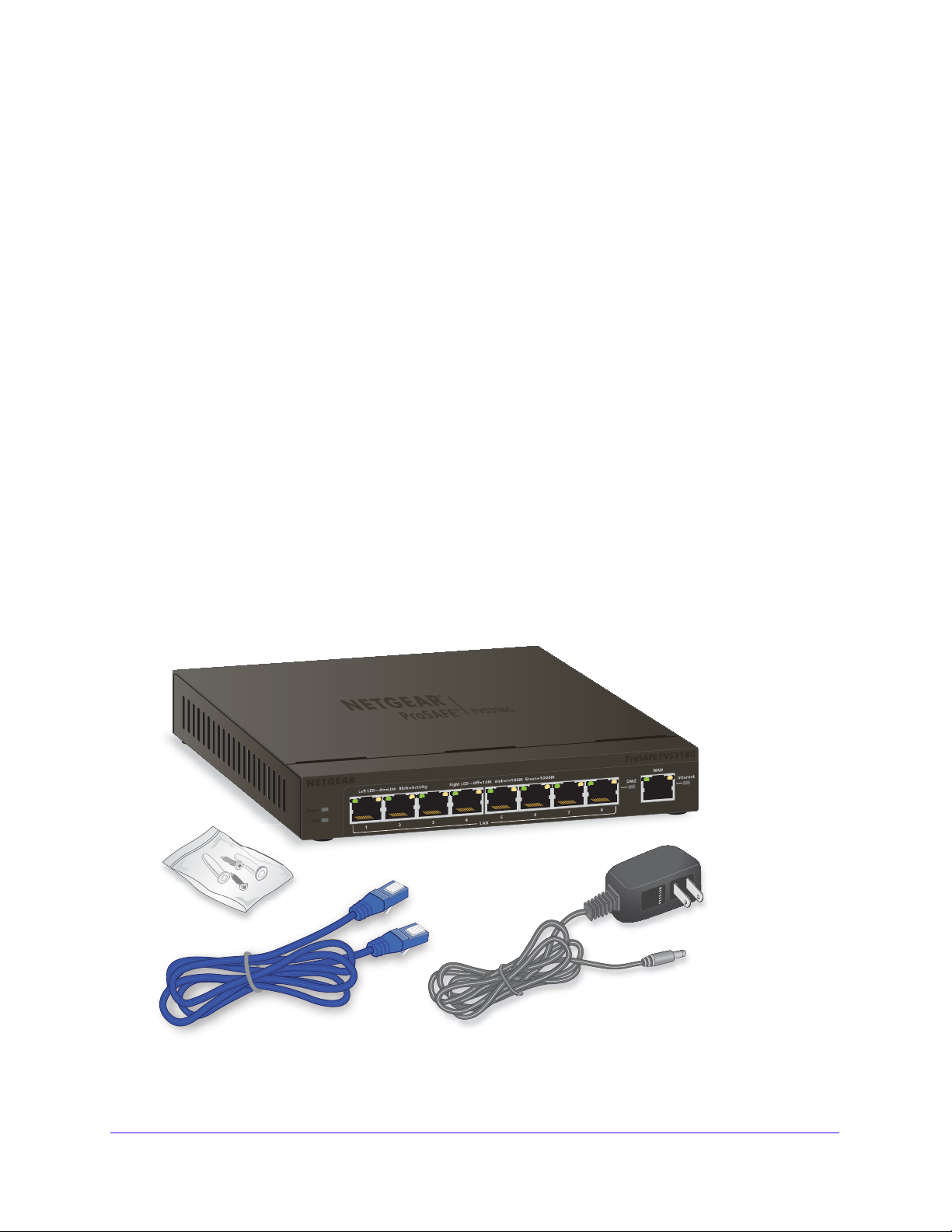
Package Contents
Figure 1. Package contents
Introduction
12
Page 13

NETGEAR ProSAFE VPN Firewall FVS318G v2
The VPN firewall product package contains the following items:
• NETGEAR ProSAFE VPN Firewall FVS318G v2
• One 12V 1A power supply unit for your region
• Mounting screws
• Ethernet cable
• NETGEAR ProSAFE VPN Firewall FVS318G v2 Inst
allation Guide
If any of the parts are incorrect, missing, or damaged, contact your NETGEAR dea
Hardware Features
The front panel ports and LEDs, rear panel ports, and bottom label of the VPN firewall are
described in the following sections.
• Front Panel
• Rear Panel
• Bottom Panel with Product Label
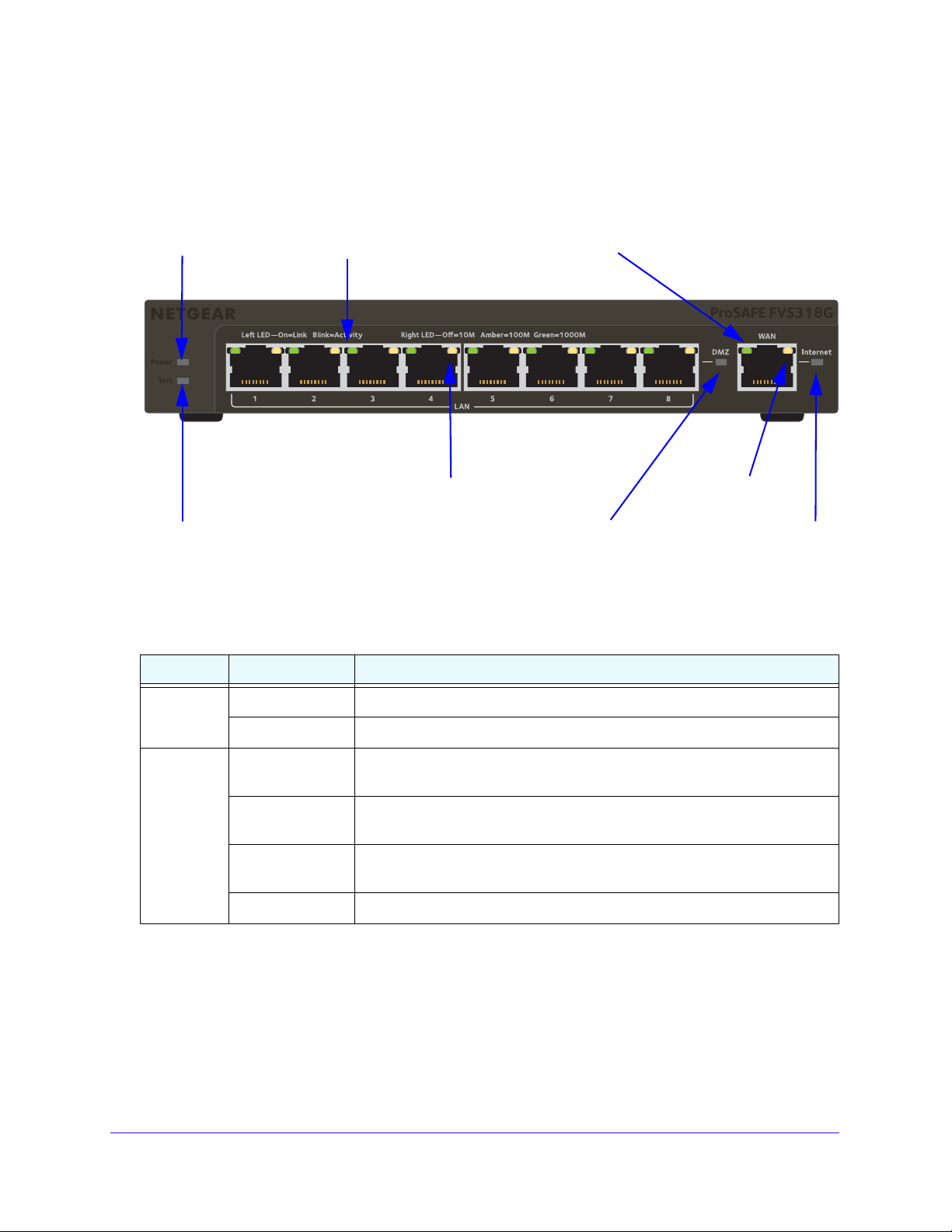
Front Panel
Viewed from left to right, the VPN firewall front panel contains the following ports:
• LAN Ethernet ports. Eight switched N-way automatic speed negotiating, Auto
MDI/MDIX, Giga
• WAN Ethernet port. On
MDI/MDIX, Gigabit Ethernet port with an RJ-45 connector.
bit Ethernet ports with RJ-45 connectors.
e independent N-way automatic speed negotiating, Auto
ler.
Introduction
13
Page 14
NETGEAR ProSAFE VPN Firewall FVS318G v2
Power
Test LED
DMZ LED
Left WAN LED
Right WAN LED
Active WAN LED
LED
Left LAN LEDs
Right LAN LEDs
(green, one for each port)
(one for each port)
(green)
The front panel also contains three groups of status indicator light-emitting diodes (LEDs),
including Power and Test LEDs, LAN LEDs, and WAN LEDs, all of which are described in
detail in the following table. Some LED explanation is provided on the front panel.
Figure 2. Front panel
The following table describes the function of each LED.
Table 1. LED descriptions
LED Activity Description
Power LED On (green) Power is supplied to the VPN firewall.
Off Power is not supplied to the VPN firewall.
Test LED On (amber) during
startup
On (amber) during
any other time
Blinking (amber) The VPN firewall is writing to flash memory (during upgrading or resetting to
Off The VPN firewall booted successfully.
Test mode. The VPN firewall is initializing. After approximately two minutes,
when the VPN firewall completes its initialization, the Test LED turns off.
The initialization failed, or a hardware failure occurred.
defaults).
Introduction
14
Page 15
NETGEAR ProSAFE VPN Firewall FVS318G v2
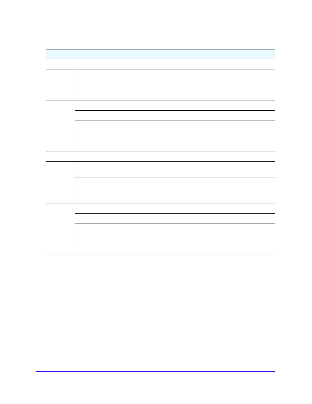
Table 1. LED descriptions (continued)
LED Activity Description
LAN Ports
Left LED Off The LAN port does not detect a link.
On (green) The LAN port detected a link with a connected Ethernet device.
Blinking (green) Data is being transmitted or received by the LAN port.
Right LED Off The LAN port is operating at 10 Mbps.
On (amber) The LAN port is operating at 100 Mbps.
On (green) The LAN port is operating at 1000 Mbps.
DMZ LED Off Port 8 is operating as a normal LAN port.
On (green) Port 8 is operating as a dedicated hardware DMZ port.
WAN Port
Left LED Off The WAN port does not detect a physical link, that is, no Ethernet cable is
plugged into the VPN firewall.
On (green) The WAN port is connected with a device that provides an Internet
connection.
Blinking (green) Data is being transmitted or received by the WAN port.
Right LED Off The WAN port is operating at 10 Mbps.
On (amber) The WAN port is operating at 100 Mbps.
On (green) The WAN port is operating at 1000 Mbps.
Active LED Off The firewall is not connected to the Internet.
On (green) The firewall is connected to the Internet.
Introduction
15
Page 16
NETGEAR ProSAFE VPN Firewall FVS318G v2
(1) Security lock
receptacle
(2) Console port
(3) Reset button
(4) DC power
receptacle
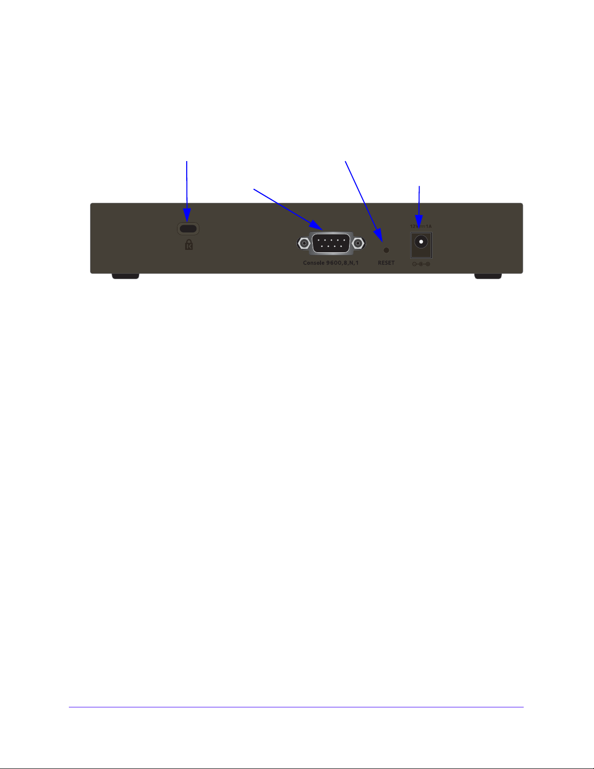
Rear Panel
The rear panel of the VPN firewall includes the antennas, a cable lock receptacle, a console
port, a Reset button, a DC power connection, and a power switch.
Figure 3. Back panel
Viewed from left to right, the rear panel contains the following components:
1. Cable security lock receptacle.
Console port.
2.
Port for connecting to an optional console terminal. The port provides a DB9
male connector. The default baud rate is 9600 K. The pinouts are (2) Tx, (3) Rx, (5) and (7)
Gnd.
3. Factory default Reset button.
Using a sharp object, press and hold this button for about
eight seconds until the front panel Test LED blinks. To reset the VPN firewall to factory
default settings. All configuration settings are lost, and the default password is restored.
4. DC power plug receptacle.
Power input is 12 VDC, 1A. The power plug is localized to the
country of sale.
Introduction
16
Page 17
NETGEAR ProSAFE VPN Firewall FVS318G v2
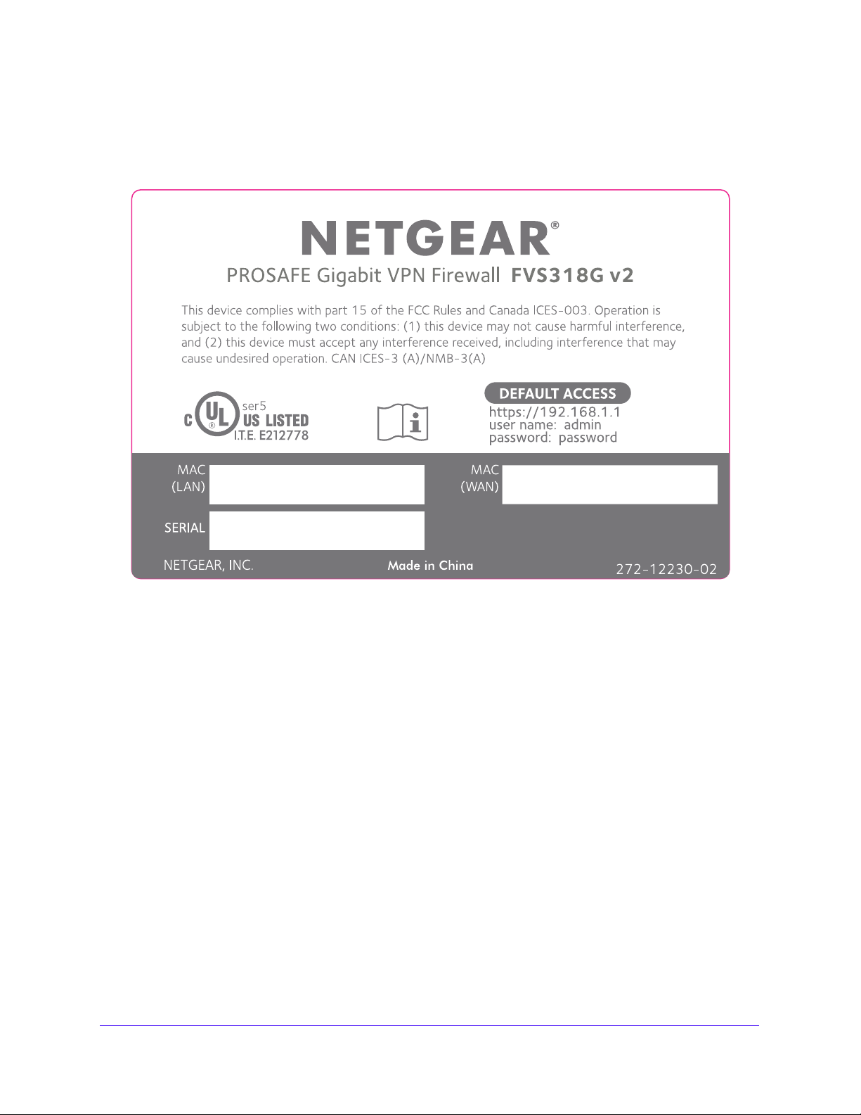
Bottom Panel with Product Label
The product label on the bottom of the VPN firewall’s enclosure displays factory default
settings, regulatory compliance, and other information.
Figure 4. Product label
Choose a Location for the VPN Firewall
The VPN firewall is suitable for use in an office environment where it can be freestanding (on
its runner feet) or mounted on a wall. Alternatively, you can rack-mount the VPN firewall in a
wiring closet or equipment room.
wa
Consider the following when deciding where to position the VPN fire
• The unit is accessible, and cables can be connected easily.
• Cabling is away from sources of electrical noise. These include lift shafts, microwave
vens, and air-conditioning units.
o
• Water or moisture cannot enter the case of the unit.
• Airflow around th
Provide a minimum of 25 mm or 1 inch clearance.
• The air is as free of dust as possible.
• Temperature operating limits are not likely to be exceeded. Inst
air-conditioned environment. For information about the recommended operating
e unit and through the vents in the side of the case is not restricted.
ll:
all the unit in a clean,
Introduction
17
Page 18
NETGEAR ProSAFE VPN Firewall FVS318G v2
temperatures for the VPN firewall, see Appendix A, Default Settings and Technical
Specifications.
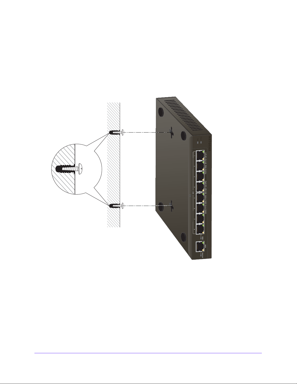
Wall-Mount the VPN Firewall with the Mounting Kit
Use the mounting kit for the VPN firewall to install the appliance on a wall. Attach the
mounting brackets using the hardware that is supplied with the mounting kit.
Figure 5. Wall mounting
Before mounting the VPN firewall to a wall, verify the following:
• You are using the correct screws (supplied with the installation kit).
• The wall on wh
ich you plan to mount the VPN firewall is suitably located.
Introduction
18
Page 19
NETGEAR ProSAFE VPN Firewall FVS318G v2
Log In to the VPN Firewall
Note: To connect the VPN firewall physically to your network, connect the
cables and restart your network according to the instructions in the
NETGEAR ProSAFE VPN Firewall FVS318G v2 Installation Guide.
To configure the VPN firewall, you must use a web browser such as Microsoft Internet
Explorer 7.0 or later, Mozilla Firefox 4.0 or later
cookies, and SSL enabled.
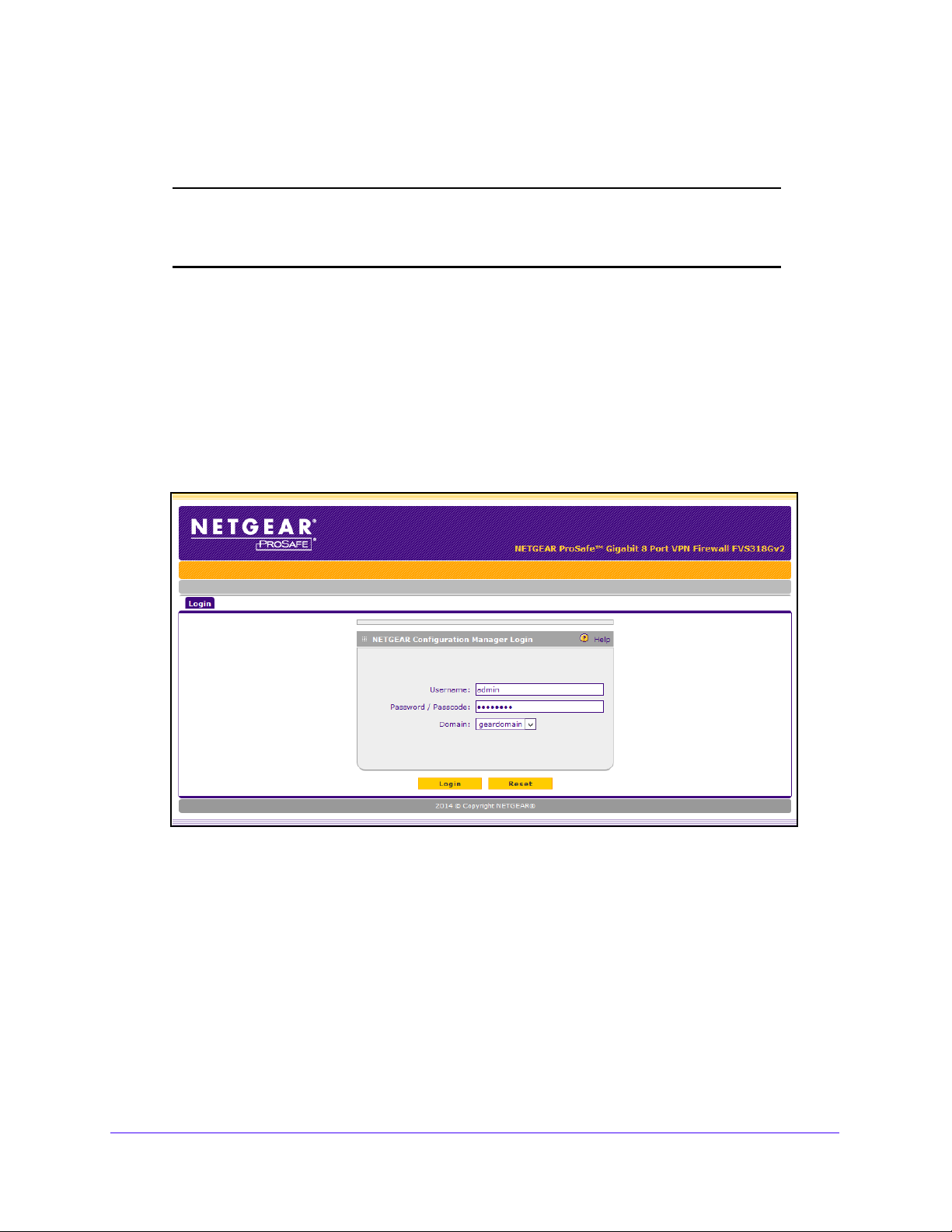
To log in to the VPN firewall:
1. Open any of the qualified web browsers.
, or Apple Safari 3.0 or later with JavaScript,
2. In the address field, enter h
The NETGEAR Configuration Manager Login screen d
The VPN firewall factory default IP address is 192.168.1.1. If you cha
you must use the IP address that you assigned to the VPN firewall to log in to the VPN
firewall.
ttps://192.168.1.1.
isplays.
nge the IP address,
3. In the Us
Use lowercase letters.
4. In the Pas
Use lowercase letters.
ername field, enter admin.
sword / Passcode field, enter password.
Introduction
19
Page 20
NETGEAR ProSAFE VPN Firewall FVS318G v2
Note: The VPN firewall user name and password are not the same as any
user name or password that you might use to log in to your Internet
connection.
Leave the domain as it is (geardomain).
5. Click the L
ogin button.
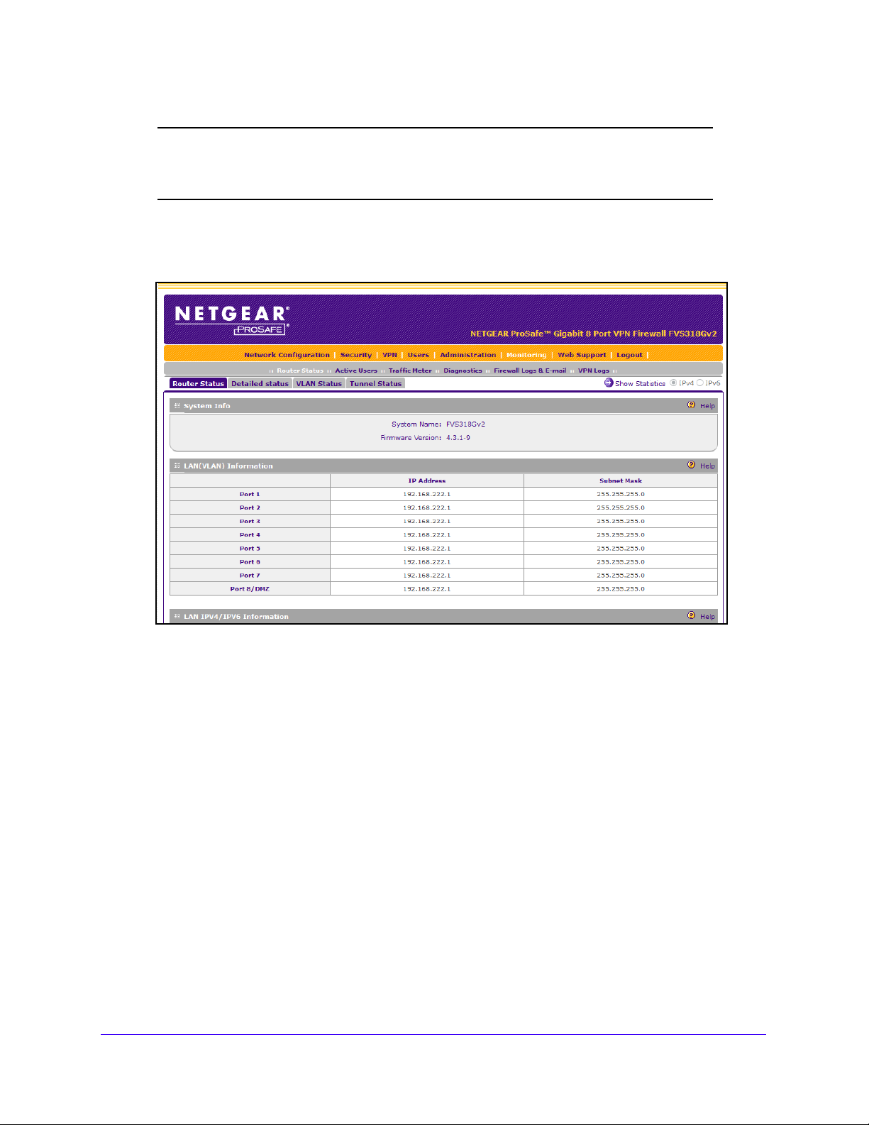
The figure shows the top part of the Router Status screen. For more inf
View the System Status on pag
e 361.
ormation, see
After five minutes of inactivity, which is the default log
logged out.
Introduction
20
in time-out, you are automatically
Page 21
NETGEAR ProSAFE VPN Firewall FVS318G v2
1st level: Main navigation menu link (orange)
2nd level: Configuration menu link (gray)
3rd level: Submenu tab (blue)
Option arrows: Additional screen for submenu item
IP radio buttons
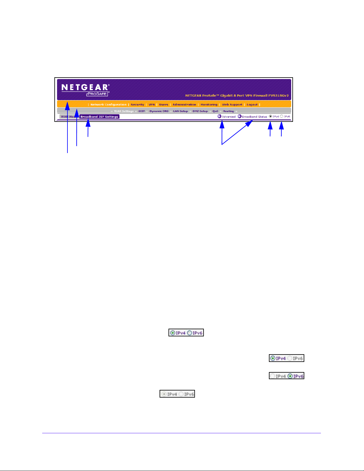
Web Management Interface Menu Layout
The following figure shows the menu at the top the web management interface:
Figure 6. Menu layout
The web management interface menu consists of the following components:
• 1st level: Main navigation menu links. The main
navigation menu in the orange bar
across the top of the web management interface provides access to all the configuration
functions of the VPN firewall and remains constant. When you select a main navigation
menu link, the letters are displayed in white against an orange background.
• 2nd level: Configuration menu links. Th
e configuration menu links in the gray bar
(immediately below the main navigation menu bar) change according to the main
navigation menu link that you select. When you select a configuration menu link, the
letters are displayed in white against a gray background.
• 3rd level: Submenu tabs.
Each configuration menu item includes one or more submenu
tabs that are listed below the gray menu bar. When you select a submenu tab, the text is
displayed in white against a blue background.
• Option arrows. If
additional screens for the submenu item are available, links to the
screens display on the right side in blue letters against a white background, preceded by
a white arrow in a blue circle.
• I
P radio buttons. The IPv
4 and IPv6 radio buttons let you select the IP version for the
feature to be configured onscreen. Four options are available:
- Both buttons are operational. Y
for IPv4 functionality or for IPv6 functionality. After you correctly
ou can configure the feature onscreen
configure the feature
for both IP versions, the feature can function with both IP versions simultaneously.
- The IPv4 button is operational but the IPv6 button is disabled. Y
can configure the feature onscreen for IPv4 functionality only.
- The IPv6 button is operational but the IPv4 button is disabled. Y
can configure the feature onscreen for IPv6 functionality only.
- Both buttons are disabled. IP f
unctionality does not apply.
ou
ou
Introduction
21
Page 22
NETGEAR ProSAFE VPN Firewall FVS318G v2
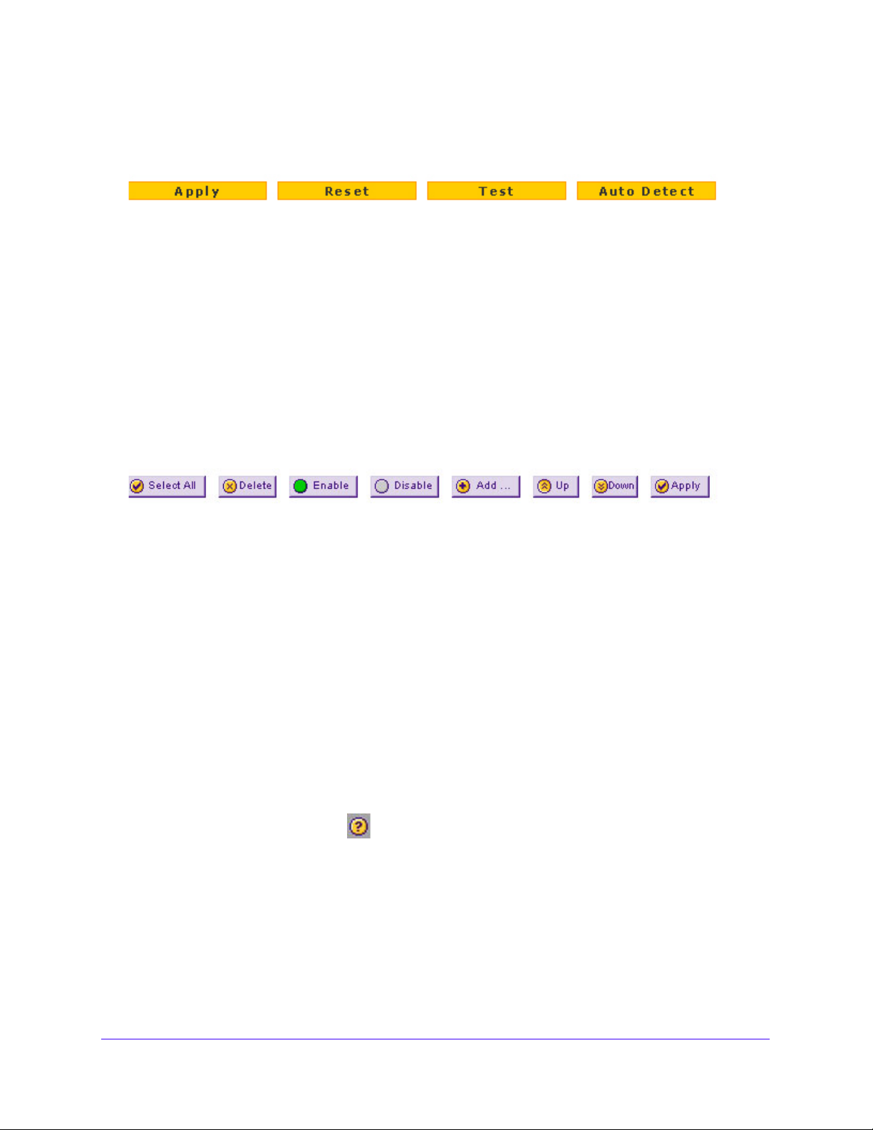
The bottom of each screen provides action buttons. The nature of the screen determines
which action buttons are shown. The following figure shows an example:
Figure 7. Action buttons
Any of the following action buttons might display onscreen (this list might not be complete):
• Apply. Save and a
• Reset. Reset the con
• Test. T
• Auto Detect. En
suggest values for the configuration.
• Cancel. Ca
When a screen includes a table, table buttons display to let you configure the t
The nature of the screen determines which table buttons are shown. The following figure
shows an example:
Figure 8. Table buttons
Any of the following table buttons might display onscreen:
• Select All. Select all entries in the
• Delete. Delete the se
• Enable. En
• Disable. Disab
• Add. Add an entry to th
• Edit. Edit the selected en
• Up. Move up the selected entry in the table.
est the configuration.
ncel the operation.
able the selected entry or entries in the table.
pply the configuration.
figuration to the previously saved configuration.
able the VPN firewall to detect the configuration automatically and
able entries.
table.
lected entry or entries from the table.
le the selected entry or entries in the table.
e table.
try.
• Down. Move down the selected entry in the table.
• Apply. Apply the selected
Almost all screens and sections of screens connect to an accompanying help
open the help screen, click the (question mark) icon.
entry.
screen. To
Requirements for Entering IP Addresses
To connect to the VPN firewall, your computer must be configured to obtain an IP address
automatically from the VPN firewall, either an IPv4 address through DHCP or an IPv6
address through DHCPv6, or both.
Introduction
22
Page 23

NETGEAR ProSAFE VPN Firewall FVS318G v2
IPv4 Addresses
The fourth octet of an IP address must be between 0 and 255 (both inclusive). This
requirement applies to any IP address that you enter on a screen of the web management
interface.
IPv6 Addresses
IPv6 addresses are denoted by eight groups of hexadecimal quartets that are separated by
colons. Any four-digit group of zeros within an IPv6 address can be reduced to a single zero
or altogether omitted.
The following errors invalidate an IPv6 address:
• More than eight groups of hexadecimal quartets
• More than four hexadecimal characters in a quartet
• More than two colons in a row
Introduction
23
Page 24

2. IPv4 and IPv6 Internet and
Broadband Settings
This chapter explains how to configure the Internet and WAN settings. The chapter contains the
following sections:
• Internet and WAN Configuration Tasks
• Configure the IPv4 Internet Connection and WAN Settings
• Configure the IPv6 Internet Connection and WAN Settings
• Configure Advanced WAN Options and Other Tasks
• Additional WAN-Related Configuration Tasks
• What to Do Next
2
24
Page 25

NETGEAR ProSAFE VPN Firewall FVS318G v2
Internet and WAN Configuration Tasks
The tasks that are required to complete the Internet connection of your VPN firewall depend
on whether you use an IPv4 connection or an IPv6 connection to your Internet service
provider (ISP). The VPN firewall supports simultaneous IPv4 and IPv6 connections.
IPv4 Internet Connections
Setting up an IPv4 Internet connection to your ISP includes five tasks, three of which are
optional.
To set up an IPv4 Internet connection:
1. Configure the IPv4 WAN mode.
Select
Mode on page 26.
2. Configure the IPv4 Internet connection to your ISP and connect t
Two configuration options are available. These tasks are described in th
sections:
• Let the VPN Firewall Automatically Detect and Configure an IPv4
• Manually Configure an IPv4 Internet Connection on p
3. (Optional) Conf
If necessary, configure your fully qualified domain names. This task is describ
Configure Dynamic DNS on p
4. (Optional) Conf
If necessary, change the factory default MTU size, port speed, and MAC add
VPN firewall. These are advanced features, and you usually do not need to change the
settings. This task is described in Configure Advanced WAN Options and Other Tasks on
pa
5. (Optional) Conf
This task is described in Enable the WAN Traffic Meter on p
either NAT or classical routing. This task is described in Configure the IPv4 WAN
o your ISP.
e following
Internet Connection
on page 28
age 31
igure Dynamic DNS on the WAN port.
ed in
age 35.
igure the WAN options.
ress of the
ge 52.
igure the WAN traffic meter.
age 349.
IPv6 Internet Connections
Setting up an IPv6 Internet connection to your ISP includes five tasks, three of which are
optional.
To set up an IPv6 Internet connection:
1. Configure the IPv6 WAN mode.
IPv4 and IPv6 Internet and Broadband Settings
25
Page 26

NETGEAR ProSAFE VPN Firewall FVS318G v2
Select the IPv4 / IPv6 mode to support both IPv4 and IPv6 traffic. For more information,
see Configure the IPv6 Routing Mode on page 39.
Configure the IPv6 Internet connection
2.
Three configuration options are available. These tasks are described in the
sections:
• Use a DHCPv6 Server to Configure an IPv6 Internet Connection on p
• Configure a Static IPv6 Internet Connection on page
• Configure a PPPoE IPv6 Internet Connection on page 44
3.
(Optional) Configure the IPv6 tunnels.
Enable 6to4
following sections:
• Configure 6to4 Automatic Tunneling o
• Configure ISATAP Automatic Tunneling on page
4. (Optional) Configure Stateless
Enable IPv6 devices that were not assigned
with IPv4-only devices. For more information, see Configure Stateless IP/ICMP
Translation on page 51
5. (Optional) Configure the WAN options.
If necessary
VPN firewall. These are advanced features, and you usually do not need to change the
settings. For more information, Configure Advanced WAN Options and Other Tasks on
page 52.
tunnels and configure ISAT
IP/ICMP Translation (SIIT).
.
, change the factory default MTU size, port speed, and MAC a
to your ISP and connect to your ISP.
following
age 40
42
AP tunnels. These tasks are described in the
n p
age 47
48
permanent IPv4 addresses to communicate
ddress of the
Configure the IPv4 Internet Connection and WAN Settings
To set up your VPN firewall for secure IPv4 Internet connections, you must determine the
IPv4 WAN mode and then configure the IPv4 Internet connection to your ISP on the WAN
port.
The web management interface offers two connection configuration
following sections:
Co
• Let the VPN Firewall Automatically Detect and
page 28
• Manually Configure an IPv4 Internet Connection on page 31
nfigure an IPv4 Internet Connection on
Configure the IPv4 WAN Mode
By default, IPv4 is supported and functions in NAT mode but can also function in classical
routing mode. IPv4 functions the same way in IPv4-only mode that it does in IPv4 / IPv6
IPv4 and IPv6 Internet and Broadband Settings
26
options, described in the
Page 27

NETGEAR ProSAFE VPN Firewall FVS318G v2
mode. The latter mode adds IPv6 functionality. For more information, see Configure the IPv6
Routing Mode on page
39.
Network Address Translation
Network Address Translation (NAT) allows all computers on your LAN to share a single public
Internet IP address. From the Internet, only a single device (the VPN firewall) and a single IP
address exist. Computers on your LAN can use any private IP address range, and these IP
addresses are not visible from the Internet.
Note the following about NAT:
• The VPN firewall uses NAT to select the correct computer (on your L
incoming data.
• If you use only a single public Internet IP address, you must use
• If your ISP provided you with mu
the primary shared address for Internet access by your computers, and you can map
incoming traffic on the other public IP addresses to specific computers on your LAN. This
one-to-one inbound mapping is configured using an inbound firewall rule.
ltiple public IP addresses, you can use one address as
AN) to receive any
NAT (the default setting).
Classical Routing
In classical routing mode, the VPN firewall performs routing, but without NAT. To gain Internet
access, each computer on your LAN must be assigned a valid static Internet IP address.
you
If your ISP allocated a number of static IP addresses to you, and
addresses to each computer, you can choose classical routing. Or you can use classical
routing for routing private IP addresses within a campus environment.
You can view the status of the WAN ports on the Router Status screen (se
Status on page 361
).
assigned one of these
e View the System
Configure the IPv4 Routing Mode
To configure the IPv4 routing mode:
1. Log in to the unit:
a. In the address field of any of the qualified web browsers, enter
The NETGEAR Configuration Manager Login screen d
b. In the Username
password.
Use lowercase letters. If you changed the password, enter your personalized
password. Leave the domain as it is (geardomain).
c. Click the Logi
The Router Status screen displays. After five minutes of inactivity
login time-out, you are automatically logged out.
field, enter admin and in the Password / Passcode field, enter
n button.
IPv4 and IPv6 Internet and Broadband Settings
27
https://192.168.1.1.
isplays.
, which is the default
Page 28

NETGEAR ProSAFE VPN Firewall FVS318G v2
WARNING:
2. Select Network Configuration > WAN Settings.
3. Select the NA
4. Click the Apply button.
Your settings are saved.
T radio button or the Classical Routing radio button.
Changing the WAN mode causes all LAN WAN and DMZ WAN
inbound rules to revert to default settings.
Let the VPN Firewall Automatically Detect and
Configure an IPv4 Internet Connection
To automatically configure the WAN port for an IPv4 connection to the Internet:
1. Log in to the unit:
a. In the address field of any of the qualified web browsers, enter
The NETGEAR Configuration Manager Login screen displays.
b. In the User
password.
name field, enter admin and in the Password / Passcode field, enter
https://192.168.1.1.
c. Click
Use lowercase letters. If you changed the password, enter your persona
password. Leave the domain as it is (geardomain).
the L
ogin button.
The Router Status screen displays. After five minutes of inactivity,
login time-out, you are automatically logged out.
IPv4 and IPv6 Internet and Broadband Settings
28
which is the default
lized
Page 29
NETGEAR ProSAFE VPN Firewall FVS318G v2
2. Select Network Configuration > WAN Settings > Broadband ISP Settings.
In the upper right of the screen, the IPv4 radio butto
n is selected by default. The ISP
Broadband Settings screen displays the IPv4 settings.
3. Click the Au
to Detect button at the bottom of the screen.
The autodetect process probes the WAN port for a range of connection meth
suggests one that your ISP is most likely to support.
The autodetect process returns one of the following results:
• If the autodetect process is successful, a status bar at the top of th
the results (for example, DHCP service detected).
IPv4 and IPv6 Internet and Broadband Settings
29
ods and
e screen displays
Page 30
NETGEAR ProSAFE VPN Firewall FVS318G v2
• If the autodetect process senses a connection method that requires input from you, it
prompts you for the information. The following table explains the settings that you
might need to enter:
Table 2. IPv4 Internet connection methods
Connection Method Manual Data Input Required
DHCP (Dynamic IP) No manual data input is required.
PPPoE The following fields are required:
• Login
• Password
• Acco
• Domain Name
PPTP The following fields are required:
• Login
• Password
• Acco
• Domain Name
• My IP Address
• Server IP Address
unt Name
unt Name
ixed (Static) IP The following fields are required:
F
• IP Address
• IP Subnet Mask
• Gateway IP Address
• Primary DNS Server
• Secondary DNS Server
• If the autodetect process does not find a connection, you are promp
check the physical connection between your VPN firewall and the cable, DSL line, or
satellite or wireless Internet dish, or to check your VPN firewall’s MAC address. For
more information, see Configure Advanced WAN Options and Other T
page 52 and Troubleshoot the ISP Connection on page 389
4. To verify the connection, click the Broadb
and Status option arrow.
ted either to
asks on
.
IPv4 and IPv6 Internet and Broadband Settings
30
Page 31

NETGEAR ProSAFE VPN Firewall FVS318G v2
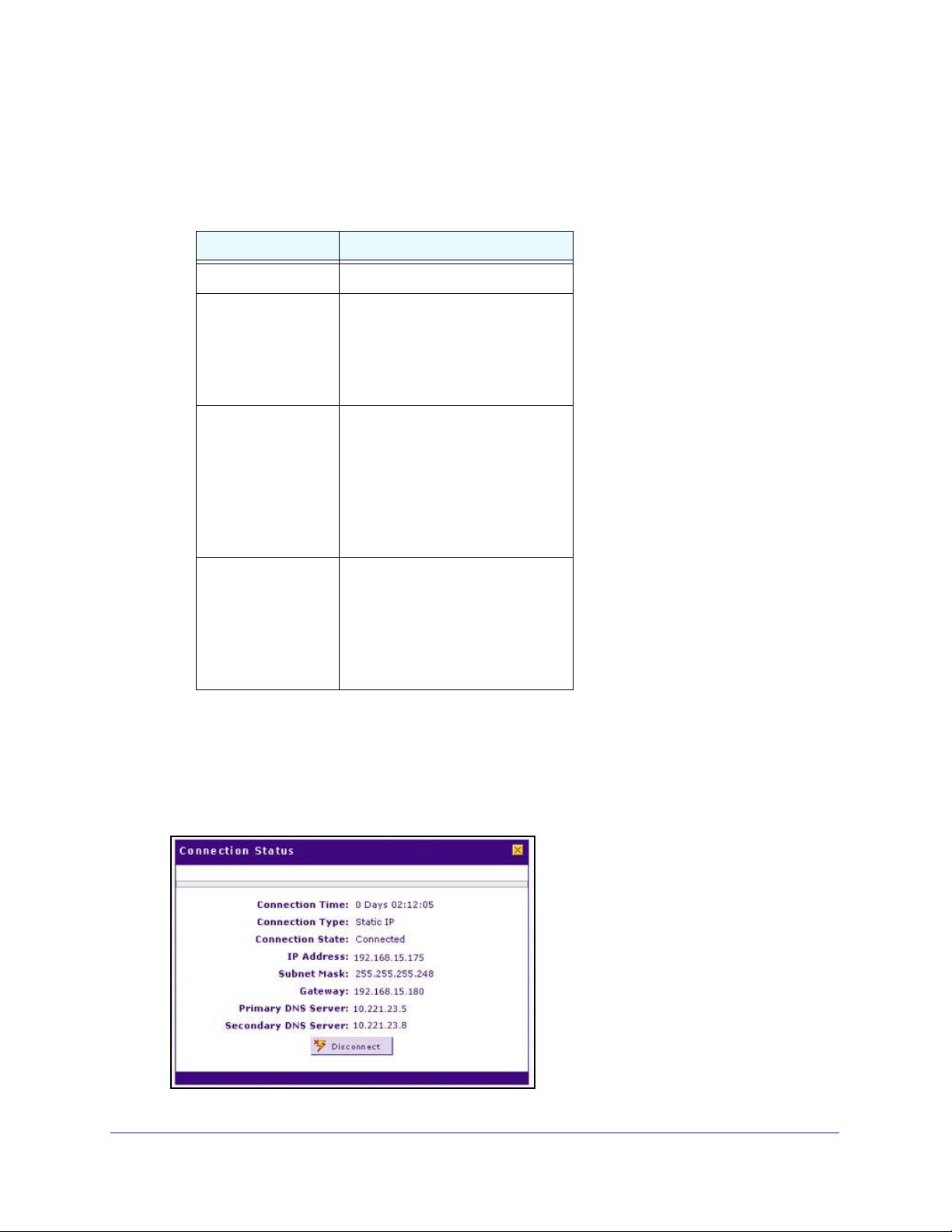
The Connection Status screen shows a valid IP address and gateway, and you are
connected to the Internet. If the configuration was not successful, skip ahead to Manually
Configure an IPv4 Internet Connection on pag
Connection on p
age 389.
e 31, or see Troubleshoot the ISP
Note: For more information about the Connection Status screen, see View
the WAN Port Status on page 373.
Manually Configure an IPv4 Internet Connection
Unless your ISP automatically assigns your configuration through a DHCP server, you must
obtain configuration parameters from your ISP to manually establish an Internet connection.
The required parameters for various connection types are listed in Tab le 2 on page 30.
To manually configure the IPv4 broadband ISP settings:
1. Log in to the unit:
a. In the address field of any of the qualified web browsers, enter
https://192.168.1.1.
The NETGEAR Configuration Manager Login screen d
b. In the Username
field, enter admin and in the Password / Passcode field, enter
isplays.
password.
Use lowercase letters. If you changed the password, enter your personalized
password. Leave the domain as it is (geardomain).
c. Click the Logi
n button.
The Router Status screen displays. After five minutes of inactivity
login time-out, you are automatically logged out.
2. Select Network Con
In the upper right of the screen, the IPv4 radio butto
figuration > WAN Settings > Broadband ISP Settings.
n is selected by default. The ISP
Broadband Settings screen displays the IPv4 settings.
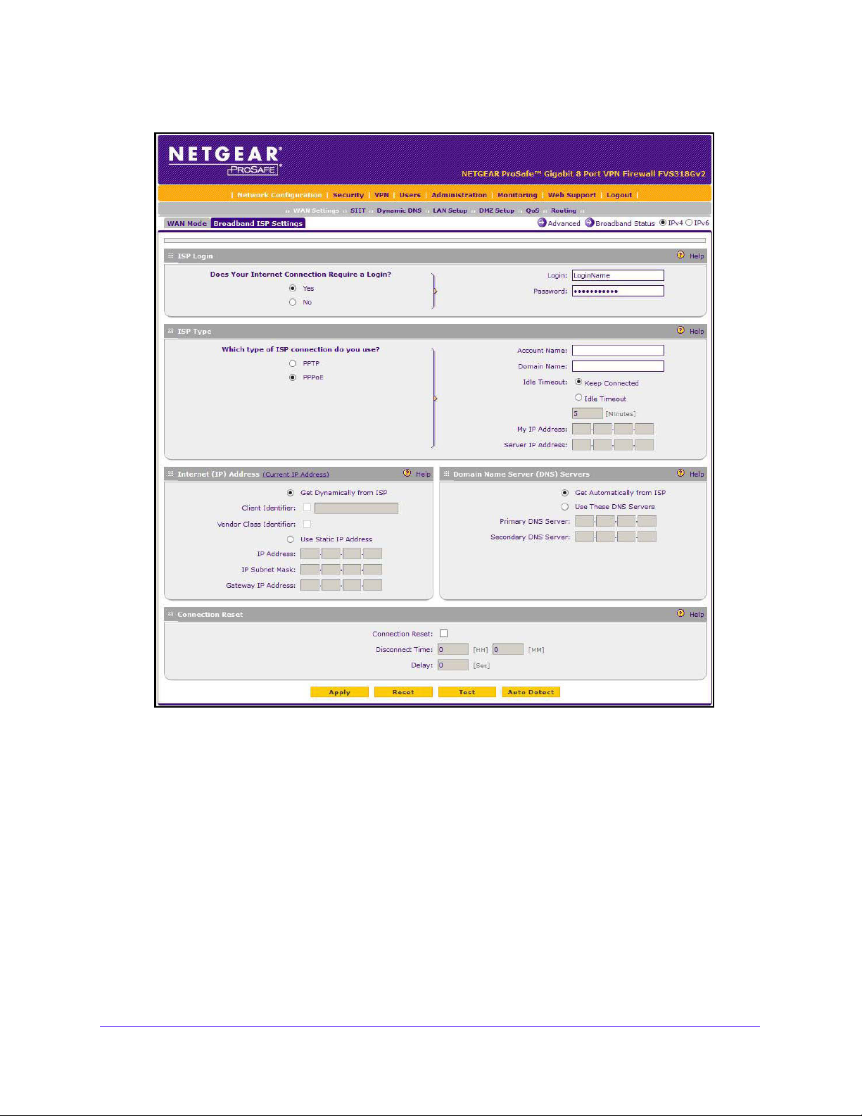
3. Locate
the ISP Login section.
4. Select one of the following options:
• If your ISP requires an initial login to establish an Internet connection
radio button. (The default is No.)
• If a login is not required, select the No radio
button, and ignore the Login and
Password fields.
, which is the default
, select the Yes
IPv4 and IPv6 Internet and Broadband Settings
31
Page 32

NETGEAR ProSAFE VPN Firewall FVS318G v2
5. If you selected the Yes radio button, enter the login name in the Login field and the
password in the Password field.
This information is provided by your ISP.
6. In the ISP Type section, select the type of ISP connection that
you use from the two listed
options.
7. If your connection is PPTP or PPPoE, your ISP requires an initial
Enter the settings as described in the following table:
Table 3. PPTP and PPPoE settings
Setting Description
PPTP
Note: For login
and password
information, see
Step 3 and Step 5.
If your ISP is Austria Telecom or any other ISP that uses PPTP for login, select this
radio button, and enter the following settings:
Account Name The account name is also known as the host name or system name.
Enter the valid account name for the PPTP connection (usually your
email ID assigned by your ISP). Some ISPs require you to enter
your full email address here.
login.
Domain Name Your domain name or workgroup name assigned by your ISP, or
your ISP’s domain name. You can leave this field blank.
Idle Timeout Select the Keep Connected radio button to keep the connection
always on. To log out after the connection is idle for a period, select
the Idle Timeout radio button and, in the Idle Timeout field, enter
the number of minutes to wait before disconnecting. This is useful if
your ISP charges you based on the period that you are logged in.
My IP Address The IP address assigned by the ISP to make the connection with the
ISP server.
Server IP
Address
The IP address of the PPTP server.
IPv4 and IPv6 Internet and Broadband Settings
32
Page 33

NETGEAR ProSAFE VPN Firewall FVS318G v2
Table 3. PPTP and PPPoE settings (continued)
Setting Description
Other (PPPoE)
Note: For login
and password
information, see
Step 3 and Step 5.
If you installed login software, your connection type is PPPoE. Select this radio button,
and enter the following settings:
Account Name The valid account name for the PPPoE connection.
Domain Name The name of your ISP’s domain or your domain name if your ISP
assigned one. You can leave this field blank.
Idle Timeout Select the Keep Connected radio button to keep the connection
always on. To log out after the connection is idle for a period, select
the Idle Timeout radio button and, in the Idle Timeout field, enter
the number of minutes to wait before disconnecting. This is useful if
your ISP charges you based on the period that you are logged in.
Connection
Reset
Select the Connection Reset check box to specify a time when the
PPPoE WAN connection is reset, that is, the connection is
disconnected momentarily and then reestablished. Then specify the
disconnect time and delay.
Disconnect
Time
Delay Specify the period in seconds after which the
Specify the hour and minutes when the connection
should be disconnected.
connection is reestablished.
8. In the Internet (IP) Address section of the screen, configure the IP address settings as
described in the following table.
See the following figure. Click the Current IP Address lin
address.
k to see the assigned IP
IPv4 and IPv6 Internet and Broadband Settings
33
Page 34

NETGEAR ProSAFE VPN Firewall FVS318G v2
Table 4. Internet IP address settings
Setting Description
Get Dynamically
from ISP
Use Static IP
Address
If your ISP did not assign you a static IP address, select the Get Dynamically from ISP
radio button. The ISP automatically assigns an IP address to the VPN firewall using
DHCP network protocol.
Client Identifier If your ISP requires the client identifier information to assign an
IP address using DHCP, select the Client Identifier check box.
Vendor Class Identifier If your ISP requires the vendor class identifier information to
assign an IP address using DHCP, select the Vendor Class
Identifier check box.
If your ISP assigned you a fixed (static or permanent) IP address, select the Use Static
IP Address radio button, and enter the following settings:
IP Address The static IP address assigned to you. This address identifies
the VPN firewall to your ISP.
IP Subnet Mask The subnet mask is usually provided by your ISP.
Gateway IP Address The IP address of the ISP’s gateway is usually provided by
your ISP.
9. In the Domain Name Server (DNS) Servers section, specify the DNS settings as described
in the following table.
See the following figure.
Table 5. DNS server settings
Setting Description
Get Automatically
SP
from I
If your ISP did not assign any Domain Name Server (DNS) addresses, select the Get
Automatically from ISP radio button.
IPv4 and IPv6 Internet and Broadband Settings
34
Page 35

NETGEAR ProSAFE VPN Firewall FVS318G v2
Table 5. DNS server settings (continued)
Setting Description
Use These DNS
Servers
If your ISP assigned DNS addresses, select the Use These DNS Servers radio
button. Make sure that you provide valid DNS server IP addresses in the fields.
Incorrect DNS entries might cause connectivity issues.
Primary DNS Server The IP address of the primary DNS server.
Secondary DNS Server The IP address of the secondary DNS server.
10. Click the Apply button.
Your settings are saved.
11. To evaluate your entries, click the T
est button.
The VPN firewall attempts to make a connection according to the settings that you
tered.
en
o verify the connection, click the Broa
12. T
dband Status option arrow.
If your ISP requires MAC authentication and another MAC address was previously
registered with yo
ur ISP, you must enter that address on the Broadband Advanced
Options screen for the WAN interface (see Configure Advanced WAN Options and Other
Tasks on page 52
).
Configure Dynamic DNS
Dynamic DNS (DDNS) is an Internet service that allows devices with varying public IPv4
addresses to be located using Internet domain names. To use DDNS, you must set up an
account with a DDNS provider such as Dyn, TZO, Oray, or 3322. (Links to Dyn, TZO, Oray,
and 3322 are provided for your convenience as option arrows on the DDNS configuration
screens.) The VPN firewall firmware includes software that notifies DDNS servers of changes
in the WAN IP address so that the services running on this network can be accessed by
others on the Internet.
If your network uses a permanently assigned IP address, you can register a domain
and link that name with your IP address using public Domain Name Servers (DNS). However,
IPv4 and IPv6 Internet and Broadband Settings
35
name
Page 36

NETGEAR ProSAFE VPN Firewall FVS318G v2
if your Internet account uses a dynamically assigned IP address, you do not know in advance
what your IP address will be, and the address can change frequently—hence, the need for a
commercial DDNS service, which allows you to register an extension to its domain and
restores DNS requests for the resulting fully qualified domain name (FQDN) to your
frequently changing IP address.
w
After you configure your account information on the VPN firewall,
hen your ISP-assigned IP
address changes, your VPN firewall automatically contacts your DDNS service provider, logs
in to your account, and registers your new IP address.
Note: If your ISP assigns a private WAN IP address such as 192.168.x.x or
10.x.x.x, the DDNS service does not work because private addresses
are not routed on the Internet.
To configure DDNS:
1. Log in to the unit:
a. In the address field of any of the qualified web browsers, enter
https://192.168.1.1.
The NETGEAR Configuration Manager Login screen displays.
b. In the User
name field, enter admin and in the Password / Passcode field, enter
password.
Use lowercase letters. If you changed the password, enter your persona
password. Leave the domain as it is (geardomain).
the L
c. Click
ogin button.
The Router Status screen displays. After five minutes of inactivity,
login time-out, you are automatically logged out.
2. Select Network Confi
guration > Dynamic DNS.
The Dynamic DNS screen displays.
3. Click the submenu tab for your DDNS service provider:
• Dynamic DNS fo
• DNS TZO fo
• DNS Oray for
• 3322 DDNS for 3
r Dyn (which is shown in the following figure)
r TZO
Oray
322
lized
which is the default
IPv4 and IPv6 Internet and Broadband Settings
36
Page 37

NETGEAR ProSAFE VPN Firewall FVS318G v2
4. For registration information, click the Information option arrow in the upper right of a DNS
screen.
For example, DynDNS Information.
t
5. Access
he website of the DDNS service provider, and register for an account.
For example, for Dyn, visit http://dyn.com/dns/.
6. Configure the DDNS service settings as described in the following table:
Table 6. DDNS service settings
Setting Description
Change DNS to
ynDNS, TZO,
(D
Oray, or 3322)
Select the Yes radio button to enable the DDNS service. The fields that display on the
screen depend on the DDNS service provider that you selected. Enter the following
settings:
Host and Domain Name The host and domain name for the DDNS service.
Username or
User Email Address
Password or User Key The password that is used for DDNS server authentication.
Use wildcards If your DDNS provider allows the use of wildcards in resolving
Update every 30 days If your WAN IP address does not often change, you must
The user name or email address for DDNS server
authentication.
your URL, you can select the Use wildcards check box to
activate this feature. For example, the wildcard feature
causes *.yourhost.dyn.com/dns to be aliased to the same IP
address as yourhost.dyn.com/dns.
force a periodic update to the DDNS service to prevent your
account from expiring. If the Update every 30 days check
box displays, select it to enable a periodic update.
7. Click the Ap
ply button.
IPv4 and IPv6 Internet and Broadband Settings
37
Page 38

NETGEAR ProSAFE VPN Firewall FVS318G v2
Your configuration is saved.
Configure the IPv6 Internet Connection and WAN Settings
The nature of your IPv6 network determines how you must configure the IPv6 Internet
connection:
• Native IPv6
IPv6 address and is connected to an IPv6 ISP and if your network consists of IPv6-only
devices.
• Isola
• Mixed network with IPv4 and IPv6 devices.
After you configure the IPv6 routing mode, you must configure the W
unicast address to enable secure IPv6 Internet connections on your VPN firewall. A global
unicast address is a public and routable IPv6 WAN address that can be statically or
dynamically assigned. The web management interface offers two connection configuration
options:
• Automatic con
• Manual configuration of the ne
ted IPv6 network.
to an IPv6 ISP, you must make sure that the IPv6 packets can travel over the IPv4
Internet backbone; you do this by enabling automatic 6to4 tunneling (see Configure 6to4
Automatic Tunneling on p
consists of both IPv4 and IPv6 devices, you must make sure that the IPv6 packets can
travel over the IPv4 intranet; you do this by enabling and configuring ISATAP tunneling
(see Configure ISATAP Automatic Tunneling on p
A network can be both an isolated IPv6 network and a mixed network wit
devices.
Configure an IPv6 Internet Connection on p
Connection on page
network. Your network is a native IPv6 network if the VPN firewall uses an
If your network is an isolated IPv6 network that is not connected
age 47).
If your network is an IPv4 network that
age 48).
h IPv4 and IPv6
A
N port with a global
figura
tion of the network connection (see Use a DHCPv6 Server to
age 40)
twork connection (see Configure a Static IPv6 Internet
42 or Configure a PPPoE IPv6 Internet Connection on page 44)
This section contains the following topics:
• Configure the IPv6 Routing Mode
• Use a DHCPv6 Server to Configure an IPv6 Internet Connection
• Configure a Static IPv6 Internet Connection
• Configure a PPPoE IPv6 Internet Connection
• Configure 6to4 Automatic Tunneling
• Configure ISATAP Automatic Tunneling
• View the Tunnel Status and IPv6 Addresses
• Configure Stateless IP/ICMP Translation
IPv4 and IPv6 Internet and Broadband Settings
38
Page 39

NETGEAR ProSAFE VPN Firewall FVS318G v2
Configure the IPv6 Routing Mode
By default, the VPN firewall supports IPv4 only. To use IPv6, you must enable the VPN
firewall to support both devices with IPv4 addresses and devices with IPv6 addresses. The
routing mode does not include an IPv6-only option; however, you can still configure a native
IPv6 network if your ISP supports IPv6. These are the options:
• IPv4-only mode. The VPN firewall communicates only with devices that use IPv4
ddresses.
a
• IPv4/IPv6 mode. The VPN firewall communicates with bot
addresses and devices that use IPv6 addresses.
h devices that use IPv4
IPv6 always functions in classical routing mode be
interfaces; NAT does not apply to IPv6.
To configure the IPv6 routing mode:
1. Log in to the unit:
a. In the address field of any of the qualified web browsers, enter
The NETGEAR Configuration Manager Login screen d
b. In the Username
field, enter admin and in the Password / Passcode field, enter
password.
Use lowercase letters. If you changed the password, enter your personalized
password. Leave the domain as it is (geardomain).
c. Click the Logi
n button.
The Router Status screen displays. After five minutes of inactivity
login time-out, you are automatically logged out.
2. Select Net
work Configuration > WAN Settings.
tween th
e WAN interface and the LAN
https://192.168.1.1.
isplays.
, which is the default
3. Select the IPv4
/ IPv6 mode radio button.
By default, the IPv4 only mode radio
IPv4 and IPv6 Internet and Broadband Settings
button is selected, and IPv6 is disabled.
39
Page 40

NETGEAR ProSAFE VPN Firewall FVS318G v2
WARNING:
Changing the IP routing mode causes the VPN firewall to reboot.
4. Click the Apply button.
Your settings are saved.
Use a DHCPv6 Server to Configure an IPv6 Internet Connection
The VPN firewall can autoconfigure its ISP settings through a DHCPv6 server by using either
stateless or stateful address autoconfiguration:
• Stateless address autoconfiguration. The
by using a combination of locally available information and router advertisements, but
receives DNS server information from a DHCPv6 server.
Router advertisements include a prefix that identifies the subnet that is associated
the WAN port. The IP address is formed by a combination of this prefix and the MAC
address of the WAN port. The IP address is a dynamic address.
As an option for stateless address autoconfiguration, the ISP’s st
can assign a prefix through prefix delegation. The VPN firewall’s own stateless DHCPv6
server can assign this prefix to its IPv6 LAN clients. For more information about prefix
delegation, see Stateless DHCPv6 Server with Prefix Delegation on page
• Stateful address autoconfiguration. Th
configuration information such as DNS server information, and other parameters from a
DHCPv6 server. The IP address is a dynamic address.
To automatically configure the WAN port for an IPv6 connection to the Internet:
1. Log in to the unit:
a. In the address field of any of the qualified web browsers, enter
The NETGEAR Configuration Manager Login screen displays.
b. In the User
password.
name field, enter admin and in the Password / Passcode field, enter
VPN firewall generates its own IP address
a
teful DHCPv6 server
79.
e VPN firewall obtains an interface address,
https://192.168.1.1.
with
Use lowercase letters. If you changed the password, enter your persona
password. Leave the domain as it is (geardomain).
c. Click
2. Select Network Confi
The Broadband ISP Settings screen displays.
the L
The Router Status screen displays. After five minutes of inactivity,
login time-out, you are automatically logged out.
lized
ogin button.
which is the default
guration > WAN Settings > Broadband ISP Settings.
IPv4 and IPv6 Internet and Broadband Settings
40
Page 41

NETGEAR ProSAFE VPN Firewall FVS318G v2
3. Select the IPv6 radio button.
4. In the Internet Address section, from the IPv
6 list, select DHCPv6.
5. In the DHCPv6 section, select a configuration option:
• Stateless Address Auto Configuration
• Stateful Address Auto Configuration
6. (Optional) I
f you m selected the Stateless Address Auto Configuration radio button, you
can select the Prefix Delegation check box:
• Prefix
DHCPv6 server through prefix del
delegation check box is selected. A prefix is assigned by the ISP’s stateful
egation, for example, 2001:db8:: /64. The VPN
firewall’s own stateless DHCPv6 server can assign this prefix to its IPv6 LAN clients.
For more information about prefix delegation, see Stateless DHCPv6 Server with
Prefix Delegation on p
age 79.
• Prefix delegation check box is cleared. Prefix delegation is disabled. Th
default setting.
7. Click the Ap
ply button.
Your changes are saved.
is is the
IPv4 and IPv6 Internet and Broadband Settings
41
Page 42

NETGEAR ProSAFE VPN Firewall FVS318G v2
8. To verify the connection, click the Status option arrow in the upper right of the screen.
The Connection Status screen shows a valid IP address and gateway,
and you are
connected to the Internet. If the configuration was not successful, see Troubleshoot the
ISP Connection on page
389.
For more information about the Connection Status screen, see View the WAN Port Status
on page 373.
Configure a Static IPv6 Internet Connection
To configure a static IPv6 or PPPoE IPv6 Internet connection, you must enter the IPv6
address information that you received from your ISP.
To configure static IPv6 broadband ISP settings:
1. Log in to the unit:
a. In the address field of any of the qualified web browsers, enter
The NETGEAR Configuration Manager Login screen displays.
b. In the User
name field, enter admin and in the Password / Passcode field, enter
password.
Use lowercase letters. If you changed the password, enter your persona
password. Leave the domain as it is (geardomain).
https://192.168.1.1.
lized
the L
c. Click
ogin button.
The Router Status screen displays. After five minutes of inactivity,
login time-out, you are automatically logged out.
Confi
2. Select Network
guration > WAN Settings > Broadband ISP Settings.
The Broadband ISP Settings screen displays.
IPv4 and IPv6 Internet and Broadband Settings
which is the default
42
Page 43

NETGEAR ProSAFE VPN Firewall FVS318G v2
3. Select the IPv6 radio button.
4. In the Internet Address section, from the IPv
5. In the Static IP Address section, enter the settings as described
6 list, select Static IPv6.
in the following table.
Your IPv6 ISP gave you your static IPv6 information.
Table 7. Broadband ISP Settings screen settings for a static IPv6 address
Setting Description
IPv6 Address The IP address that your ISP a
following formats (all four examples specify the same IPv6 address):
• 2001:db8:0000:0000:020f:2
• 2001:db8:0:0:20f:24ff:febf:dbcb
• 2001:db8::20f:24ff:febf:dbcb
• 2001:db8:0:0:20f:24ff:128.141.49.32
IPv6 Prefix L
Default IPv6 Gateway The IPv6 IP address of the ISP’s default IPv6 gateway.
Primary DNS Server The IPv6 IP address of the ISP’s primary DNS server.
Secondary DNS Server The IPv6 IP address of the ISP’s secondary DNS server.
6. Click the Ap
ength The prefix length that your ISP assigned to you, typically 64.
ply button.
ssigned to you. Enter the address in one of the
4ff:febf:dbcb
Your changes are saved.
IPv4 and IPv6 Internet and Broadband Settings
43
Page 44

NETGEAR ProSAFE VPN Firewall FVS318G v2
7. To verify the connection, click the Status option arrow in the upper right of the screen.
The Connection Status screen shows a valid IP address and gateway,
and you are
connected to the Internet. If the configuration was not successful, see Troubleshoot the
ISP Connection on page
389.
For more information about the Connection Status screen, see View the WAN Port Status
on page 373.
vio
If your ISP requires MAC authentication and another MAC address was pre
usly
registered with your ISP, you must enter that address on the Broadband Advanced
Options screen for the corresponding WAN interface (see Configure Advanced WAN
Options and Other Tasks on p
age 52).
Configure a PPPoE IPv6 Internet Connection
To configure a PPPoE IPv6 Internet connection, you must enter the PPPoE IPv6 information
that you received from your ISP.
To configure PPPoE IPv6 broadband ISP settings:
1. Log in to the unit:
a. In the address field of any of the qualified web browsers, enter
The NETGEAR Configuration Manager Login screen displays.
b. In the User
name field, enter admin and in the Password / Passcode field, enter
password.
https://192.168.1.1.
Use lowercase letters. If you changed the password, enter your persona
password. Leave the domain as it is (geardomain).
the L
c. Click
ogin button.
The Router Status screen displays. After five minutes of inactivity,
login time-out, you are automatically logged out.
2. Select Network Confi
guration > WAN Settings > Broadband ISP Settings.
The Broadband ISP Settings screen displays.
IPv4 and IPv6 Internet and Broadband Settings
lized
which is the default
44
Page 45

NETGEAR ProSAFE VPN Firewall FVS318G v2
3. Select the IPv6 radio button.
4. In the Internet Address section, from the IPv
5. In the PPPoE IPv6, enter the settings as described in the following
6 list, select PPPoE.
table.
Your IPv6 ISP gave you your PPPoE IPv6 information.
Table 8. Broadband ISP Settings screen settings for a PPPoE IPv6 connection
Setting Description
User Name The PPPoE user name that is provided by your ISP.
Password The PPPoE password that is provided by your ISP.
IPv4 and IPv6 Internet and Broadband Settings
45
Page 46

NETGEAR ProSAFE VPN Firewall FVS318G v2
Table 8. Broadband ISP Settings screen settings for a PPPoE IPv6 connection (continued)
Setting Description
DHCPv6 Option From the DHCPv6 Option list, select one of the following DHCPv6 server
options, as directed by your ISP:
• Disable-DHCPv6. DHCPv6 is di
the Primary DNS Server and Secondary DNS Server fields to receive an IP
address from the ISP.
• DHCPv6
using a combination of locally available information and router
advertisements but receives DNS server information from the ISP’s DHCPv6
server. Router advertisements include a prefix that identifies the subnet that
is associated with the WAN port. The IP address is formed from a
combination of this prefix and the MAC address of the WAN port. The IP
address is a dynamic address.
• DHCPv6
configuration information such as DNS server information, and other
parameters from the ISP’s DHCPv6 server. The IP address is a dynamic
address.
• DHCPv6
DHCPv6 server through prefix delegation, for example, 2001:db8::/64. The
VPN firewall’s own stateless DHCPv6 server can assign this prefix to its IPv6
LAN clients. For more information about prefix delegation, see Stateless
DHCPv6 Server with Prefix Delegation on
StatelessMode. The VPN firewall generates its own IP address by
StatefulMode. The VPN firewall obtains an interface address,
Pre
fix Delegation. The VPN firewall obtains a prefix from the ISP’s
sabled. You must specify the DNS servers in
page 79.
Primary DNS Server If you selected Disable-DHCPv6 from the DHCPv6 Options list, the IPv6 IP
address of the ISP’s primary DNS server.
Secondary DNS Server If you selected Disable-DHCPv6 from the DHCPv6 Options list, the IPv6 IP
address of the ISP’s secondary DNS server.
6. Click the Apply button.
Your changes are saved.
7. To verify the connection, click the St
The Connection Status pop-up screen displays, which shows a static IP addres
atus option arrow in the upper right of the screen.
s
configuration; the screen for PPPoE is similar.)
,
The Connection Status screen shows a valid IP address and gateway
and you are
connected to the Internet. If the configuration was not successful, see Troubleshoot the
ISP Connection on page
389.
For more information about the Connection Status screen, see View the WAN Port Status
on page 373.
vio
If your ISP requires MAC authentication and another MAC address was pre
usly
registered with your ISP, you must enter that address on the Broadband Advanced
Options screen for the corresponding WAN interface (see Configure Advanced WAN
Options and Other Tasks on p
age 52).
IPv4 and IPv6 Internet and Broadband Settings
46
Page 47

NETGEAR ProSAFE VPN Firewall FVS318G v2
Configure 6to4 Automatic Tunneling
If your network is an isolated IPv6 network that is not connected to an IPv6 ISP, you must
make sure that the IPv6 packets can travel over the IPv4 Internet backbone by enabling
automatic 6to4 tunneling.
6to4 is a WAN tunnel mechanism for automatic tunneling of IPv6 traffic between
a device
with an IPv6 address and a device with an IPv4 address, or the other way around. 6to4
tunneling is used to transfer IPv6 traffic between LAN IPv6 hosts and WAN IPv6 networks
over the IPv4 network.
With 6to4 tunnels, IPv6 packets are embedded within the IPv4 packet and th
en transported
over the IPv4 network. You do not need to specify remote tunnel endpoints, which are
automatically determined by relay routers on the Internet. You cannot use 6to4 tunnels for
traffic between IPv4-only devices and IPv6-only devices.
If the VPN firewall functions as the
endpoint for 6to4 tunnels in your network, make sure that
the VPN firewall uses a static IPv4 address (see Manually Configure an IPv4 Internet
Connection on p
age 31). A dynamic IPv4 address can cause routing problems on the 6to4
tunnels.
If you do not use a stateful DHCPv6 server in your LAN, you must configure th
Ad
vertisement Daemon (RADVD), and set up 6to4 advertisement prefixes for 6to4 tunneling
to function correctly. For more information, see Manage the IPv6 LAN on p
Typically, 6to4 tunnel addresses start with a 2002 prefix (decimal no
tification). On the VPN
e Router
age 78.
firewall, a 6to4 tunnel is indicated by sit0-WAN1 (see View the Tunnel Status and IPv6
Addresses on page 51).
To enable 6to4 automatic tunneling:
1. Log in to the unit:
a. In the address field of any of the qualified web browsers, enter
The NETGEAR Configuration Manager Login screen d
b. In the Username
field, enter admin and in the Password / Passcode field, enter
password.
Use lowercase letters. If you changed the password, enter your personalized
password. Leave the domain as it is (geardomain).
c. Click the Logi
n button.
The Router Status screen displays. After five minutes of inactivity
login time-out, you are automatically logged out.
https://192.168.1.1.
isplays.
, which is the default
IPv4 and IPv6 Internet and Broadband Settings
47
Page 48

NETGEAR ProSAFE VPN Firewall FVS318G v2
2. Select Network Configuration > WAN Settings > 6 to 4 Tunneling.
3. Select the En
4. Click the Appl
able Automatic Tunneling check box.
y button.
Your changes are saved.
Configure ISATAP Automatic Tunneling
If your network is an IPv4 network or IPv6 network that consists of both IPv4 and IPv6
devices, you must make sure that the IPv6 packets can travel over the IPv4 intranet by
enabling and configuring Intra-Site Automatic Tunnel Addressing Protocol (ISATAP)
tunneling.
ISATAP is a LAN tunnel mechanism in which the IPv4 network function
local link. Each IPv4 address is mapped to a link-local IPv6 address, that is, the IPv4 address
is used in the interface portion of the IPv6 address. ISATAP tunneling is used intra site, that
is, between addresses in the LAN. For more information about link-local addresses, see
Manage the IPv6 LAN on page 78.
If you do
not use a stateful DHCPv6 server in your LAN, you must configure
Advertisement Daemon (RADVD) and set up ISATAP advertisement prefixes (which are
referred to as Global/Local/ISATAP prefixes) for ISATAP tunneling to function correctly. For
more information, see Manage the IPv6 LAN on pag
The VPN firewall determines the link-local address by co
e 78.
ncatenating the IPv6 address with
the 32 bits of the IPv4 host address:
s as a virtual IPv6
the Router
e
• For a uniqu
global address:
fe80:0000:0000:0000:0000:5efe (or fe80::5efe) is concatenated with the IPv4 add
For example, fe80::5efe with 10.29.33.4 becomes fe80::5efe:10.29.33.4, or in
hexadecimal format, fe80::5efe:a1d:2104.
• For a private add
0000:0000:0000:0200:5efe (or fe80::200:5efe) is concatenated with t
fe80:
ress:
address. For example, fe80::200:5efe with 192.168.1.1 becomes
fe80::200:5efe:192.168.1.1, or in hexadecimal format, fe80::200:5efe:c0a8:101.
To configure an ISATAP tunnel:
1. Log in to the unit:
a. In the address field of any of the qualified web browsers, enter
The NETGEAR Configuration Manager Login screen displays.
IPv4 and IPv6 Internet and Broadband Settings
ress.
he IPv4
https://192.168.1.1.
48
Page 49

NETGEAR ProSAFE VPN Firewall FVS318G v2
b. In the Username field, enter admin and in the Password / Passcode field, enter
password.
Use lowercase letters. If you changed the password, enter your personalized
password. Leave the domain as it is (geardomain).
c. Click
The Router Status screen displays. After five minutes of inactivity
login time-out, you are automatically logged out.
2. Select Net
3. Click
the Ad
the Logi
n button.
work Configuration > WAN Settings > ISATAP Tunnels.
d table button under the List of Available ISATAP Tunnels table.
, which is the default
4. Specify the tunnel settings as described in the following table.
Table 9. Add ISATAP Tunnel screen settings
Setting Description
ISATAP Subnet Prefix The IPv6 prefix for the tunnel.
Local End
Address
IPv4 Address If you select Othe
5. Click the Ap
Point
ply button.
From the list, select the type of local address:
• LAN. The local endpoint address is the address of the default VLAN.
• Other IP.
must specify in the IPv4 Address fields.
address.
The local endpoint address is another LAN IP address that you
r IP from the Local End Point Address list, enter the IPv4
Your changes are saved.
To edit an ISATAP tunnel:
1. Log in to the unit:
IPv4 and IPv6 Internet and Broadband Settings
49
Page 50

NETGEAR ProSAFE VPN Firewall FVS318G v2
a. In the address field of any of the qualified web browsers, enter https://192.168.1.1.
The NETGEAR Configuration Manager Login screen displays.
b. In the User
name field, enter admin and in the Password / Passcode field, enter
password.
Use lowercase letters. If you changed the password, enter your persona
password. Leave the domain as it is (geardomain).
c. Click the L
ogin button.
The Router Status screen displays. After five minutes of inactivity,
login time-out, you are automatically logged out.
Confi
2. Select Network
guration > WAN Settings > ISATAP Tunnels.
The ISATAP Tunnels screen displays.
3. In the Action column for the tunnel that you want to modify, click
The Edit ISATAP Tunnel screen displays. This screen is identical to the Add
Tunnel screen.
4. Modif
y the settings as described in T
5. Click the Appl
y button.
able 9 on page 49.
Your changes are saved.
To delete one or more tunnels:
1. Log in to the unit:
lized
which is the default
the Edit button.
ISATAP
a. In the address field of any of the qualified web browsers, enter
https://192.168.1.1.
The NETGEAR Configuration Manager Login screen displays.
b. In the User
name field, enter admin and in the Password / Passcode field, enter
password.
Use lowercase letters. If you changed the password, enter your persona
lized
password. Leave the domain as it is (geardomain).
the L
c. Click
The Router Status screen displays. After five minutes of inactivity,
ogin button.
which is the default
login time-out, you are automatically logged out.
Confi
2. Select Network
guration > WAN Settings > ISATAP Tunnels.
The ISATAP Tunnels screen displays.
3. Select the check box to the left of each tunnel that you want to delete or click the Sele
table button to select all tunnels.
4. Click the Appl
y button.
Your changes are saved.
ct All
IPv4 and IPv6 Internet and Broadband Settings
50
Page 51

NETGEAR ProSAFE VPN Firewall FVS318G v2
View the Tunnel Status and IPv6 Addresses
The IPv6 Tunnel Status screen displays the status of all active 6to4 and ISATAP tunnels and
their IPv6 addresses.
To view the status of the tunnels and IPv6 addresses:
1. Log in to the unit:
a. In the address field of any of the qualified web browsers, enter
The NETGEAR Configuration Manager Login screen d
b. In the Username
password.
Use lowercase letters. If you changed the password, enter your personalized
password. Leave the domain as it is (geardomain).
c. Click
2. Select Moni
3. View the IPv6 Tunnel Status table fields:
• Tunnel Name. The tunnel name for the 6to4 tunnel is always sit0-WAN1 (SIT st
• IPv6 Address. T
the Logi
The Router Status screen displays. After five minutes of inactivity
login time-out, you are automatically logged out.
toring
for simple Internet transition); the tunnel name for an ISATAP tunnel is isatapx-LAN,
in which x is an integer.
field, enter admin and in the Password / Passcode field, enter
n button.
> Router Status > Tunnel Status.
he IPv6 address of the local tunnel endpoint.
isplays.
https://192.168.1.1.
, which is the default
ands
Configure Stateless IP/ICMP Translation
Stateless IP/ICMP Translation (SIIT) is a transition mechanism algorithm that translates
between IPv4 and IPv6 packet headers. Using SIIT, an IPv6 device that does not use a
permanently assigned IPv4 addresses can communicate with an IPv4-only device.
SIIT functions with IPv4-translated addresses, which are addresses in the format
0
::ffff:0:0:0/96 for IPv6-enabled devices. You can substitute an IPv4 address in the format
a.b.c.d for part of the IPv6 address so that the IPv4-translated address becomes
0::ffff:0:a.b.c.d/96.
For SIIT to function, the routing mode must be IPv4 / IPv6. NETGEAR’
SIIT lets you enter a single IPv4 address on the SIIT screen. This IPv4 address is then used
IPv4 and IPv6 Internet and Broadband Settings
51
s implementation of
Page 52

NETGEAR ProSAFE VPN Firewall FVS318G v2
in the IPv4-translated address for IPv6 devices to enable communication between IPv4-only
devices on the VPN firewall’s LAN and IPv6-only devices on the WAN.
To configure SIIT:
1. Log in to the unit:
a. In the address field of any of the qualified web browsers, enter
The NETGEAR Configuration Manager Login screen displays.
https://192.168.1.1.
b. In the User
password.
Use lowercase letters. If you changed the password, enter your persona
password. Leave the domain as it is (geardomain).
c. Click the L
The Router Status screen displays. After five minutes of inactivity,
login time-out, you are automatically logged out.
2. Select Network
3. Select the En
4. In the SIIT
address for IPv6 devices.
5. Click the Appl
name field, enter admin and in the Password / Passcode field, enter
ogin button.
Confi
able SIIT check box.
Address fields, enter the IPv4 address to be used in the IPv4-translated
y button.
lized
which is the default
guration > SIIT.
Your changes are saved.
Configure Advanced WAN Options and Other Tasks
The advanced options include configuring the maximum transmission unit (MTU) size, port
speed, and VPN firewall’s MAC address, and setting a rate limit on the traffic that is being
forwarded by the VPN firewall.
Although you can access the Broadband Advanced Options screen only through the
Broadba
WAN connections.
To configure advanced WAN options:
1. Log in to the unit:
nd ISP Settings (IPv4) screen, the advanced options apply to both IPv4 and IPv6
IPv4 and IPv6 Internet and Broadband Settings
52
Page 53

NETGEAR ProSAFE VPN Firewall FVS318G v2
a. In the address field of any of the qualified web browsers, enter https://192.168.1.1.
The NETGEAR Configuration Manager Login screen d
b. In the Username
field, enter admin and in the Password / Passcode field, enter
password.
Use lowercase letters. If you changed the password, enter your personalized
password. Leave the domain as it is (geardomain).
c. Click
the Logi
n button.
The Router Status screen displays. After five minutes of inactivity
login time-out, you are automatically logged out.
2. Select Network Con
figuration > WAN Settings > Broadband ISP Settings.
The Broadband ISP Settings screen displays the IPv4 settings.
3. Click the Ad
vanced option arrow in the upper right of the screen.
isplays.
, which is the default
4. Enter the settings as described in the following table:
Table 10. Broadband Advanced Options screen settings
Setting Description
MTU Size
Make one of the following selections:
Default S
elect the Default radio button for the normal maximum transmit unit (MTU)
value. For most Ethernet networks, this value is 1500 bytes, or 1492 bytes for
PPPoE connections.
IPv4 and IPv6 Internet and Broadband Settings
53
Page 54

NETGEAR ProSAFE VPN Firewall FVS318G v2
Table 10. Broadband Advanced Options screen settings (continued)
Setting Description
Custom Select the Custom radio button, and enter an MTU value in the Bytes field. For
some ISPs, you might need to reduce the MTU. This is rarely required. Do not
do this unless you are sure that it is necessary for your ISP connection.
Speed
In most cases, the VPN firewall can automatically determine the connection speed of the WAN port of the
device (modem, dish, or router) that provides the WAN connection. If you cannot establish an Internet
connection, you might need to manually select the port speed. If you know the Ethernet port speed of the
modem, dish, or router, select it from the mlist. Use the half-duplex settings only if the full-duplex settings do
not function correctly.
Select one of the following speeds from them list:
autosensing. This is the default setting. The firewall can sense all Ethernet speeds
• AutoSense. S
and duplex modes, including 1000BASE-T speed at full duplex.
• 10BaseT Half_Duplex.
• 10BaseT Full_Duplex.
• 100BaseT Half_Duplex. Fast Ethernet speed at half duplex.
• 100BaseT Full_Duplex.
• 1000BaseT Half_Duplex.
• 1000BaseT Full_Duplex. Gigabit Ethernet speed at full duplex.
peed
Ethernet speed at half duplex.
Ethernet speed at full duplex.
Fast Ethernet speed at full duplex.
Gigabit Ethernet speed at half duplex.
Router’s MAC Address
Each computer or router on your network is assigned a unique 48-bit local Ethern
referred to as the computer’s Media Access Control (MAC) address. By default the Use Default Address
radio button is selected.
Make one of the following selections:
Use Default Address Each computer or router on your network is assigned a unique 32-bit local
Ethernet address. This is also referred to as the computer’s Media Access
Control (MAC) address. To use the VPN firewall’s own MAC address, select the
Use Default Address radio button.
Use this computer’s MAC
Address
Use this MAC Address Select the Use this MAC Address radio button, and manually enter the MAC
Upload/Download Settings
You can configure the WAN's maximum bandwidth of upstream and downstream settings for the other
components in the system to operate optimally.
Select the Use this computer’s MAC Address radio button to allow the VPN
firewall to use the MAC address of the computer that you are now using to
access the web management interface. This setting is useful if your ISP requires
MAC authentication.
address in the field next to the radio button. You would typically enter the MAC
address that your ISP requires for MAC authentication.
Note: The format for the MAC address is 01:23:45:67:89:AB (numbers
0–9 and either uppercase or lowercase letters A–F). If you enter a MAC address,
the existing entry is overwritten.
et address. This is also
WAN connection type The type of connection being used to connect to the internet.
IPv4 and IPv6 Internet and Broadband Settings
54
Page 55

NETGEAR ProSAFE VPN Firewall FVS318G v2
Table 10. Broadband Advanced Options screen settings (continued)
Setting Description
WAN connection speed
upload
WAN connection speed
download
The maximum bandwidth of upstream provided by your Internet service
provider.
The maximum bandwidth of downstream provided by your Internet service
provider.
5. Click the Apply button.
Your changes are saved.
Additional WAN-Related Configuration Tasks
If you want the ability to manage the VPN firewall remotely, enable remote management (see
Configure Remote Management Access on p
NETGEAR strongly recommends that you cha
and Administrator and Guest Settings on p
You can also set up the traffic meter for the WAN interface. See Enable the WAN Traffic
Meter on p
age 34
9.
Verify the Connection
Test the VPN firewall before deploying it in a live production environment. Verify that network
traffic can pass through the VPN firewall:
age 328). If you enable remote management,
nge your password (see Change Passwords
age 326).
• Ping an
Interne
• Ping the IP addre
t URL.
ss of a device on either side of the VPN firewall.
What to Do Next
You completed setting up the WAN connection for the VPN firewall. The following chapters
and sections describe important tasks that you must address before you deploy the VPN
firewall in your network:
• Chapter 3, LAN Configuration
• Configure Authentication Domains, Groups, and Users on
• Manage Digital Certificates for VPN Connections on page
• Use the IPSec VPN Wizard for Client and Gateway Configurations on pag
age 287
p
308
e 213
IPv4 and IPv6 Internet and Broadband Settings
55
Page 56

3. LAN Configuration
This chapter describes how to configure the LAN features of your VPN firewall. The chapter
contains the following sections:
• Manage IPv4 Virtual LANs and DHCP Options
• Configure IPv4 Multihome LAN IP Addresses on the Default VLAN
• Manage IPv4 Groups and Hosts (IPv4 LAN Groups)
• Manage the IPv6 LAN
• Configure IPv6 Multihome LAN IP Addresses on the Default VLAN
• Enable and Configure the DMZ Port for IPv4 and IPv6 Traffic
• Manage Static IPv4 Routing
• Manage Static IPv6 Routing
• Configure Quality of Service
3
56
Page 57

NETGEAR ProSAFE VPN Firewall FVS318G v2
Manage IPv4 Virtual LANs and DHCP Options
A local area network (LAN) can generally be defined as a broadcast domain. Hubs, bridges,
or switches in the same physical segment or segments connect all end node devices.
Endpoints can communicate with each other without the need for a router. Routers connect
LANs together, routing the traffic to the appropriate port.
A virtual LAN (VLAN) is a local area network with a definition that maps workst
some basis other than geographic location (for example, by department, type of user, or
primary application). To enable traffic to flow between VLANs, traffic must go through a
router, as if the VLANs were on two separate LANs.
A VLAN is a group of computers, servers, and other network resources that
were connected to a single network segment—even though they might not be. For example,
all marketing personnel might be spread throughout a building. Yet if they are all assigned to
a single VLAN, they can share resources and bandwidth as if they were connected to the
same segment. The resources of other departments can be invisible to the marketing VLAN
members, accessible to all, or accessible only to specified individuals, depending on how the
IT manager sets up the VLANs.
VLANs offer a number of advantages:
t is easy to set up
• I
each other can be grouped into common VLANs, regardless of physical location. Each
group’s traffic is contained largely within the VLAN, reducing extraneous traffic and
improving the efficiency of the whole network.
• T
hey are easy to manage. The addition
can be dealt with quickly and conveniently from a management interface rather than from
the wiring closet.
• They provide increased performance. VLANs free up bandwidth by limit
and broadcast traffic throughout the network.
• They ensure enhanced network security. VLANs create virtual boun
crossed only through a router. So standard, router-based security measures can be used
to restrict access to each VLAN.
network segmentation. Users who communicate most frequently with
of nodes, as well as moves and other changes,
daries that can be
ations on
behave as if they
ing node-to-node
This section contains the following topics:
• Port-Based VLANs
• Assign and Manage VLAN Profiles
• VLAN DHCP Options
• Configure a VLAN Profile
• Configure VLAN MAC Addresses and LAN Advanced Settings
Port-Based VLANs
The VPN firewall supports port-based VLANs. Port-based VLANs help to confine broadcast
traffic to the LAN ports. Even though a LAN port can be a member of more than one VLAN,
the port can use only one VLAN ID as its port VLAN identifier (PVID). By default, all eight
LAN Configuration
57
Page 58

NETGEAR ProSAFE VPN Firewall FVS318G v2
LAN ports of the VPN firewall are assigned to the default VLAN, or VLAN 1. Therefore, by
default, all eight LAN ports use the default PVID 1. However, you can assign another PVID to
a LAN port by selecting a VLAN profile from the list on the LAN Setup screen.
After you create a VLAN profile and assign one or more ports to the
profile, you must enable
the profile to activate it.
The VPN firewall’s default VLAN cannot be deleted. All untagged tra
ffic is routed through the
default VLAN (VLAN1), which you must assign to at least one LAN port.
Note the following about VLANs and PVIDs:
• One physical port is assigned to at least one VLAN.
• One physical port can be assigned to multiple VLANs.
• When one port is assigned to multiple VLANs, the port is used as a trunk port to connect
to an
other switch or router.
• When a port receives an untagged packet, this packet is forwarded
to a VLAN based on
the PVID.
• When a port receives a tagged packet, this packet is forwarded to
a VLAN based on the
ID that is extracted from the tagged packet.
nable
When you create a VLAN profile, assign LAN ports to the VLAN, and e
the VLAN, the
LAN ports that are members of the VLAN can send and receive both tagged and untagged
packets. Untagged packets that enter these LAN ports are assigned to the default PVID 1;
packets that leave these LAN ports with the same default PVID 1 are untagged. All other
packets are tagged according to the VLAN ID that you assigned to the VLAN when you
created the VLAN profile.
This is a typical scenario for a configuration with an IP phone that include
s two Ethernet
ports, one of which is connected to the VPN firewall, the other one to another device.
Packets coming from the IP phone to the VPN firewall LAN port are t
agged. Packets passing
through the IP phone from the connected device to the VPN firewall LAN port are untagged.
When you assign the VPN firewall LAN port to a VLAN, packets entering and leaving the port
are tagged with the VLAN ID. However, untagged packets entering the VPN firewall LAN port
are forwarded to the default VLAN with PVID 1; packets that leave the LAN port with the
same default PVID 1 are untagged.
The configuration of the DHCP options for the default VLAN is des
IPv4 Internet Connection and WAN Settings on pag
and edit a VLAN profile, including its
DHCP options, see Configure a VLAN Profile on
e 26. For information about how to add
cribed in Configure the
page 61.
Assign and Manage VLAN Profiles
To assign VLAN profiles to the LAN ports and manage VLAN profiles:
1. Log in to the unit:
a. In the address field of any of the qualified web browsers, enter
https://192.168.1.1.
LAN Configuration
58
Page 59

NETGEAR ProSAFE VPN Firewall FVS318G v2
The NETGEAR Configuration Manager Login screen displays.
b. In the Username
password.
Use lowercase letters. If you changed the password, enter your personalized
password. Leave the domain as it is (geardomain).
c. Click
the Logi
The Router Status screen displays. After five minutes of inactivity
login time-out, you are automatically logged out.
2. Select Network
field, enter admin and in the Password / Passcode field, enter
n button.
, which is the default
Con
figuration > LAN Setup.
For each VLAN profile, the following fields display in the VLAN Profiles table:
• Che
• S
• Profile Name. Th
• VLAN ID. The uniq
• Subnet IP. The subne
• DHCP St
ck box. Allows you to select the VLAN profile in the table.
tatus icon. Indicates the status of the VLAN profile:
- Green circ
- Gray circle. The
le. The VLAN profile is enabled.
VLAN profile is disabled.
e unique name assigned to the VLAN profile.
ue ID (or tag) assigned to the VLAN profile.
t IP address for the VLAN profile.
atus. The DHCP server status for the VLAN profile, which can be either
Enabled or Disabled.
• Action. T
3. Assign a VLAN profile to a LAN port by selecting a VLAN profile
he Edit table button, which provides access to the Edit VLAN Profile screen.
from the list.
The enabled VLAN profiles are displayed in the lists.
4. Click the Ap
ply button.
Your settings are saved.
LAN Configuration
59
Page 60

NETGEAR ProSAFE VPN Firewall FVS318G v2
VLAN DHCP Options
For each VLAN, you must specify the Dynamic Host Configuration Protocol (DHCP) options.
For more information, see Configure a VLAN Profile on p
age 61.
For more information about the configuration of the DHCP options for the VPN
default VLAN, or VLAN 1, see Configure the IPv4 Internet Connection and WAN Settings on
page 26.
• DHCP Server
• DHCP Relay
• DNS Proxy
• LDAP Server
For information about the DHCP options, see the following sections:
firewall’s
DHCP Server
The DHCP server option for the default VLAN (VLAN 1) is enabled by default, allowing the
VPN firewall to assign IP, DNS server, WINS server, and default gateway addresses to all
computers connected to the VPN firewall’s LAN. The assigned default gateway address is
the LAN address of the VPN firewall. IP addresses are assigned to the attached computers
from a pool of addresses that you must specify. Each pool address is tested before it is
assigned to avoid duplicate addresses on the LAN. When you create a VLAN, the DHCP
server option is disabled by default.
For most applications, the default DHCP server and TCP/IP settin
satisfactory.
The VPN firewall delivers the following settings to any LAN device that requests
gs of the VPN firewall are
DHCP:
• An IP address from the ran
• Subnet mask
• Gateway IP address (the VPN firewall’s LAN IP address)
• Primary DNS server (the
• WINS server (if you entered a WINS server address in the DHCP Setup screen)
• Lease time (the date
obtained and the duration of the lease)
ge that you defined
VPN firewall’s LAN IP address)
DHCP Relay
DHCP relay options allow you to make the VPN firewall a DHCP relay agent for a VLAN. The
DHCP relay agent makes it possible for DHCP broadcast messages to be sent over routers
that do not support forwarding of these types of messages. The DHCP relay agent is
therefore the routing protocol that enables DHCP clients to obtain IP addresses from a DHCP
server on a remote subnet. If you do not configure a DHCP relay agent for a VLAN, its clients
can obtain IP addresses only from a DHCP server that is on the same subnet. To enable
clients to obtain IP addresses from a DHCP server on a remote subnet, you must configure
the DHCP relay agent on the subnet that contains the remote clients so that the DHCP relay
agent can relay DHCP broadcast messages to your DHCP server.
LAN Configuration
60
Page 61

NETGEAR ProSAFE VPN Firewall FVS318G v2
DNS Proxy
When the DNS proxy option is enabled for a VLAN, the VPN firewall acts as a proxy for all
DNS requests and communicates with the ISP’s DNS servers (as configured on the
Broadband ISP Settings screens). All DHCP clients receive the primary and secondary DNS
IP addresses along with the IP address where the DNS proxy is located (that is, the VPN
firewall’s LAN IP address). When the DNS proxy option is disabled for a VLAN, all DHCP
clients receive the DNS IP addresses of the ISP but without the DNS proxy IP address.
LDAP Server
A Lightweight Directory Access Protocol (LDAP) server allows a user to query and modify
directory services that run over TCP/IP. For example, clients can query email addresses,
contact information, and other service information using an LDAP server. For each VLAN,
you can specify an LDAP server and a search base that defines the location in the directory
(that is, the directory tree) from which the LDAP search begins.
Configure a VLAN Profile
For each VLAN on the VPN firewall, you can configure its profile, port membership, LAN
TCP/IP settings, DHCP options, DNS server, and inter-VLAN routing capability.
After you complete the LAN setup, all outbound traffic is allowed
discarded except responses to requests from the LAN side.
To add a VLAN profile:
1. Log in to the unit:
a. In the address field of any of the qualified web browsers, enter
The NETGEAR Configuration Manager Login screen d
b. In the Username
password.
Use lowercase letters. If you changed the password, enter your personalized
password. Leave the domain as it is (geardomain).
c. Click
the Logi
The Router Status screen displays. After five minutes of inactivity
login time-out, you are automatically logged out.
field, enter admin and in the Password / Passcode field, enter
n button.
and a
isplays.
ll inbound traffic is
https://192.168.1.1.
, which is the default
LAN Configuration
61
Page 62

NETGEAR ProSAFE VPN Firewall FVS318G v2
2. Select Network Configuration > LAN Setup.
For information about how to manage VLANs, see Port-Based VLANs on p
following information describes how to config
ure a VLAN profile.
age 57. The
LAN Configuration
62
Page 63

NETGEAR ProSAFE VPN Firewall FVS318G v2
3. Under the VLAN Profiles table, click the Add table button.
4. Enter the settings as described in the following table:
Table 11. Add VLAN Profile screen settings
Setting Description
VLAN Profile
Profile Name Enter a unique name for the VLAN profile
VLAN ID Enter a unique ID number for the VLAN profile. No two VLANs can use the same
VLAN ID number.
Note: You can enter VLAN IDs from 2 to 4089. VLAN ID 1 is reserved for the
default VLAN; VLAN ID 4094 is reserved for the DMZ interface.
LAN Configuration
63
.
Page 64

NETGEAR ProSAFE VPN Firewall FVS318G v2
Table 11. Add VLAN Profile screen settings (continued)
Setting Description
Port Membership
Port 1, Port 2, Port 3,
Port 4, Port 5, Port 6,
Port 7, and
Port 8 / DMZ
IP Setup
IP Address Enter the IP address of t
Subnet Mask Enter the IP subnet mask. The subnet mask specifies the network number portion
DHCP
Disable DHCP Server If another device on your network is the DHCP server for the VLAN, or if you
Select one, several, or all port check boxes to make the ports members of this
VLAN.
Note: A port that is defined as a member of a VLAN profile can send and receive
data frames that are tagged with the VLAN ID.
he VP
N firewall (the factory default address is
192.168.1.1).
Note: Ensure that the LAN port IP address and DMZ port IP address are in
different subnets.
Note: If you change the LAN IP address of the VLAN while being connected
through the browser to the VLAN, you are disconnected. You then must open a
new connection to the new IP address and log in again. For example, if you change
the default IP address 192.168.1.1 to 10.0.0.1, you now must enter
https://10.0.0.1 in your browser to reconnect to the web management interface.
of an IP address. Based on the IP address that you assign, the VPN firewall
automatically calculates the subnet mask. Unless you are implementing
subnetting, use 255.255.255.0 as the subnet mask (computed by the VPN
firewall).
intend to manually configure the network settings of all of your computers, select
the Disable DHCP Server radio button to disable the DHCP server. Except for
the default VLAN for which the DHCP server is enabled, this is the default setting.
LAN Configuration
64
Page 65

NETGEAR ProSAFE VPN Firewall FVS318G v2
Table 11. Add VLAN Profile screen settings (continued)
Setting Description
Enable DHCP Server Select the Enable DHCP Server radio button to enable the VPN firewall to
function as a Dynamic Host Configuration Protocol (DHCP) server, providing
TCP/IP configuration for all computers connected to the VLAN. (For the default
VLAN, the DHCP server is enabled by default.) Enter the following settings:
Domain Name This setting is optional. Enter the domain name of the VPN
firewall.
Start IP Enter the start IP address. This address specifies the first of
the contiguous addresses in the IP address pool. Any new
DHCP client joining the LAN is assigned an IP address
between this address and the end IP address. For the default
VLAN, the default start IP address is 192.168.1.100.
End IP Enter the end IP address. This address specifies the last of
the contiguous addresses in the IP address pool. Any new
DHCP client joining the LAN is assigned an IP address
between the start IP address and this IP address. For the
default VLAN, the default end IP address is 192.168.1.254.
The start and end DHCP IP addresses must be in the same
network as the LAN IP address of the VPN firewall (that is, the
IP address in the IP Setup section as described earlier in this
table).
Primary DNS
Server
Secondary DNS
Server
WINS Server This setting is optional. Enter a WINS server IP address to
Lease Time Enter a lease time. This specifies the duration for which IP
DHCP Relay To use the VPN firewall as a DHCP relay agent for a DHCP server somewhere
else in your network, select the DHCP Relay radio button. Enter the following
setting:
Relay Gateway The IP address of the DHCP server for which the VPN firewall
This setting is optional. If an IP address is specified, the VPN
firewall provides this address as the primary DNS server IP
address. If no address is specified, the VPN firewall uses the
VLAN IP address as the primary DNS server IP address.
This setting is optional. If an IP address is specified, the VPN
firewall provides this address as the secondary DNS server IP
address.
specify the Windows NetBIOS server if one is present in your
network.
addresses are leased to clients.
serves as a relay.
LAN Configuration
65
Page 66

NETGEAR ProSAFE VPN Firewall FVS318G v2
Table 11. Add VLAN Profile screen settings (continued)
Setting Description
Enable LDAP
information
DNS Proxy
Enable DNS Proxy This setting is o
To enable the DHCP server to provide Lightweight Directory Access Protocol
(LDAP) server information, select the Enable LDAP information check box.
Enter the following settings:
LDAP Server The IP address or name of the LDAP server.
Search Base The search objects that specify the location in the directory
Port The port number for the LDAP server. The default setting is 0
for DNS address name resolution, select the Enable DNS Proxy check box. This
feature is disabled by default.
tree from which the LDAP search begins. You can specify
multiple search objects, separated by commas. The search
objects include the following:
• CN
• OU (for organizational unit)
• O (for organization)
• C (for country)
• DC (for domain)
Fo
names of Johnson, you would enter
cn=Johnson,dc=Netgear,dc=net
(zero).
ptional. To enable the VPN firewall to provide a LAN IP address
(for common name)
r example, to search the Netgear.net domain for all last
Inter VLAN Routing
Enable Inter VLAN
Routing
5. Click the Apply button.
Your settings are saved.
To edit a VLAN profile:
1. Log in to the unit:
a. In the address field of any of the qualified web browsers, enter
The NETGEAR Configuration Manager Login screen displays.
b. In the User
name field, enter admin and in the Password / Passcode field, enter
password.
Note: When the DNS proxy option is disabled for a VLAN, all DHCP clients
receive the DNS IP addresses of the ISP but without the DNS proxy IP address.
This setting is optional. To ensure that traffic is routed only to VLANs for which
inter-VLAN routing is enabled, select the Enable Inter VLAN Routing check box.
This feature is disabled by default. When the Enable Inter VLAN Routing check
box is not selected, traffic from this VLAN is not routed to other VLANs, and traffic
from other VLANs is not routed to this VLAN.
https://192.168.1.1.
LAN Configuration
66
Page 67

NETGEAR ProSAFE VPN Firewall FVS318G v2
Use lowercase letters. If you changed the password, enter your personalized
password. Leave the domain as it is (geardomain).
c. Click
the Logi
n button.
The Router Status screen displays. After five minutes of inactivity
login time-out, you are automatically logged out.
Con
2. Select Network
figuration > LAN Setup.
The LAN Setup screen displays.
3. For the VLAN profile that you want to modify, in the Action column,
The Edit VLAN Profile screen displays. This screen is identical to the Add VLAN Profile
scre
en.
4. Modify the settings as described in T
5. Click the Ap
ply button.
able 11 on page 63.
Your settings are saved.
To enable, disable, or delete one or more VLAN profiles:
1. Log in to the unit:
a. In the address field of any of the qualified web browsers, enter
The NETGEAR Configuration Manager Login screen d
b. In the Username
field, enter admin and in the Password / Passcode field, enter
password.
, which is the default
click the Edit button.
https://192.168.1.1.
isplays.
Use lowercase letters. If you changed the password, enter your personalized
password. Leave the domain as it is (geardomain).
c. Click
the Logi
n button.
The Router Status screen displays. After five minutes of inactivity
login time-out, you are automatically logged out.
2. Select Network Con
figuration > LAN Setup.
The LAN Setup screen displays.
3. Select the check box to the left of each VLAN profile that you want
delete, or click the Select All table button to select all profiles.
You cannot select the default VLAN profile.
4. Click one of the following table buttons:
• Enable
. Enables the VLAN or VLANs.
The ! status icon changes from a gray circle to a green circle, indica
selected VLAN or VLANs are enabled. By default, when a VLAN is added to the table,
it is automatically enabled.
• Disable. Disables the VLAN or VLANs.
, which is the default
to enable, disable, or
ting that the
LAN Configuration
67
Page 68

NETGEAR ProSAFE VPN Firewall FVS318G v2
The ! status icon changes from a green circle to a gray circle, indicating that the
selected VLAN or VLANs are disabled.
VL
• Delete. Deletes the VLAN or
ANs.
Configure VLAN MAC Addresses and LAN Advanced Settings
By default, all configured VLAN profiles share the same single MAC address as the LAN
ports. (All LAN ports share the same MAC address.) However, you can change the VLAN
MAC settings to allow up to 16 VLANs to each be assigned a unique MAC address.
If you attempt to configure more than 16 VLANs while the MAC address for VLANs is set to
Uniqu
e on the LAN Advanced screen, the MAC addresses that are assigned to each VLAN
might no longer be distinct.
You can also enable or disable the broadcast of Address Resolution Protocol (ARP) p
for the default VLAN. If the broadcast of ARP packets is enabled, IP addresses can be
mapped to physical addresses (that is, MAC addresses).
To configure a VLAN to use a unique MAC address:
1. Log in to the unit:
a. In the address field of any of the qualified web browsers, enter
https://192.168.1.1.
The NETGEAR Configuration Manager Login screen displays.
b. In the User
name field, enter admin and in the Password / Passcode field, enter
password.
Use lowercase letters. If you changed the password, enter your persona
password. Leave the domain as it is (geardomain).
the L
c. Click
The Router Status screen displays. After five minutes of inactivity,
ogin button.
which is the default
login time-out, you are automatically logged out.
2. Select Network Confi
In the upper right of the screen, the IPv4 radio bu
guration > LAN Setup.
tton is selected by default. The LAN
submenu tabs display, with the LAN Setup screen in view, displaying the IPv4 settings.
ackets
lized
LAN Configuration
68
Page 69

NETGEAR ProSAFE VPN Firewall FVS318G v2
3. In the upper middle of the LAN Setup screen, click the Advanced option arrow.
4. From the MAC
The default is Same.
5. (Optional) Disable
Enable ARP Broadcast check box.
The broadcast of ARP packets is enabled by default for the default VLAN.
6. Click the Ap
Your settings are saved.
Address for VLANs list, select Unique.
the broadcast of ARP packets for the default VLAN by clearing the
ply button.
Configure IPv4 Multihome LAN IP Addresses on the Default VLAN
If computers on your LAN use different IPv4 networks (for example, 172.124.10.0 or
192.168.200.0), you can add aliases to the LAN ports and give computers on those networks
access to the Internet, but you can do so only for the default VLAN. The IP address that is
assigned as a secondary IP address must be unique and cannot be assigned to a VLAN.
Secondary IP addresses cannot be configured in the DHCP server. The host
secondary subnets must be manually configured with the IP addresses, gateway IP address,
and DNS server IP addresses.
s on the
Make sure that any secondary LAN addresses are different from the
DMZ IP addresses and subnet addresses that are already configured on the VPN firewall.
The following is an example of correctly configured IPv4 addresses:
AN IP address. 10.0.0.1 with subnet 255.0.0.0
• W
• DMZ IP address
• Primary LAN IP address. 1
• Secondary LAN IP address. 192
To add a secondary LAN IPv4 address:
1. Log in to the unit:
. 176.16.2.1 with subnet 255.255.255.0
92.168.1.1 with subnet 255.255.255.0
.168.20.1 with subnet 255.255.255.0
LAN Configuration
69
primary LAN, WAN, and
Page 70

NETGEAR ProSAFE VPN Firewall FVS318G v2
a. In the address field of any of the qualified web browsers, enter https://192.168.1.1.
The NETGEAR Configuration Manager Login screen displays.
b. In the User
password.
Use lowercase letters. If you changed the password, enter your persona
password. Leave the domain as it is (geardomain).
c. Click the L
The Router Status screen displays. After five minutes of inactivity,
login time-out, you are automatically logged out.
d. Click
the L
The Router Status screen displays. After five minutes of inactivity,
login time-out, you are automatically logged out.
2. Select Network
name field, enter admin and in the Password / Passcode field, enter
lized
ogin button.
which is the default
ogin button.
which is the default
Confi
guration > LAN Setup > LAN Multi-homing.
The Available Secondary LAN IPs table displays the secondary LAN IP
to the VPN firewall.
3. In the Add Secondary LAN IP Address section, enter the following
• IP Address. Enter the secondary addre
• Subnet Mask. En
ter the subnet mask for the secondary IP address.
ss that you want to assign to the LAN ports.
4. To add the secondary IP address to the Available Secondary LAN IPs
column, click the Add table button.
5. Repeat St
ep 3 and Step 4 for each secondary IP address that you want to add to the
Available Secondary LAN IPs table.
To edit a secondary LAN IP address:
1. Log in to the unit:
a. In the address field of any of the qualified web browsers, enter
The NETGEAR Configuration Manager Login screen displays.
b. In the User
name field, enter admin and in the Password / Passcode field, enter
password.
addresses added
settings:
table, in the rightmost
https://192.168.1.1.
LAN Configuration
70
Page 71

NETGEAR ProSAFE VPN Firewall FVS318G v2
Use lowercase letters. If you changed the password, enter your personalized
password. Leave the domain as it is (geardomain).
c. Click
2. Select Network
The LAN Multi-homing screen displays.
3. In the Action column for the secondary IP address that you want
button.
The Edit LAN Multi-homing screen displays.
4. Modify the IP address or subnet mask or both.
5. Click the Ap
Your settings are saved.
To delete one or more secondary LAN IP addresses:
1. Log in to the unit:
a. In the address field of any of the qualified web browsers, enter
b. In the Username
the Logi
The Router Status screen displays. After five minutes of inactivity
login time-out, you are automatically logged out.
The NETGEAR Configuration Manager Login screen d
password.
n button.
Con
figuration > LAN Setup > LAN Multi-homing.
ply button.
field, enter admin and in the Password / Passcode field, enter
, which is the default
to modify, click the Edit
https://192.168.1.1.
isplays.
Use lowercase letters. If you changed the password, enter your personalized
password. Leave the domain as it is (geardomain).
c. Click
2. Select Network
The LAN Multi-homing screen displays.
3. Select the check box to the left of each secondary IP address that you want to delete or click
the Sel
4. Click the Del
The information is deleted.
the Logi
The Router Status screen displays. After five minutes of inactivity
login time-out, you are automatically logged out.
ect All table button to select all secondary IP addresses.
n button.
Con
figuration > LAN Setup > LAN Multi-homing.
ete table button.
, which is the default
Manage IPv4 Groups and Hosts (IPv4 LAN Groups)
The Known PCs and Devices table on the LAN Groups (IPv4) screen lists all known
computers and network devices that are assigned dynamic IP addresses by the VPN firewall,
were discovered by other means, or were entered manually. Collectively, these entries make
LAN Configuration
71
Page 72

NETGEAR ProSAFE VPN Firewall FVS318G v2
up the network database. For more information, see Manage the Network Database on
page 73.
The network database is updated by these methods:
• DHCP cli
ent reques
ts. When the DHCP server is enabled, it accepts and responds to
DHCP client requests from computers and other network devices. These requests also
generate an entry in the network database. This is an advantage of enabling the DHCP
server feature.
• Scanning
the network. The local network is scanned using Address Resolution Protocol
(ARP) requests. The ARP scan detects active devices that are not DHCP clients.
In large networks, scanning the network might genera
te unwanted traffic. When the VPN
firewall receives a reply to an ARP request, it might not be able to determine the device
name if the software firewall of the device blocks the name.
• Manual entry. Y
ou can manually enter information about a network device.
These are some advantages of the network database:
• Generally, you do not need to enter an IP address or a MAC address. Instead,
you can
select the name of the desired computer or device.
• You do not need to reserve an IP address for a computer in the DHCP server. All IP
addre
ss assignments made by the DHCP server are maintained until the computer or
device is removed from the network database, either by expiration (inactive for a long
time) or by you.
• You do not need to use a fixed IP address on a computer. Because the
IP address
allocated by the DHCP server never changes, you do not need to assign a fixed IP
address to a computer to ensure that it always uses the same IP address.
• A compute
is identified by its MAC address—not its IP address. The network database
r
uses the MAC address to identify each computer or device. Therefore, changing a
computer’s IP address does not affect any restrictions applied to that computer.
• Control over
- You can assign computers to groups (see Manage the Network Database on t
computers can be assigned to groups and individuals:
his
page) and apply restrictions (outbound rules and inbound rules) to each group (see
Overview of Rules to
Block or Allow Specific Kinds of
- You can select groups that are allowed access to
Traffic on page 127).
URLs that you blocked for other
groups, or the other way around, block access to URLs that you allowed access to for
groups (see Configure Content Filtering on page
189).
- If necessary, you can also create firewall rules t
Enable Source MAC Filtering on p
age 196). Because the MAC address is used to
identify each computer, users cannot avoid these restrictions by changing the
address.
This section contains the following topics:
• Manage the Network Database
• Change Group Names in the Network Database
LAN Configuration
72
o apply to a single computer (see
ir IP
Page 73

NETGEAR ProSAFE VPN Firewall FVS318G v2
• DHCPv6 Server Options
Manage the Network Database
You can view the network database, manually add or remove database entries, and edit
database entries. The Known PCs and Devices table lists the entries in the network
database.
To view the network database:
1. Log in to the unit:
a. In the address field of any of the qualified web browsers, enter
https://192.168.1.1.
The NETGEAR Configuration Manager Login screen d
b. In the Username
password.
Use lowercase letters. If you changed the password, enter your personalized
password. Leave the domain as it is (geardomain).
c. Click the Logi
The Router Status screen displays. After five minutes of inactivity
login time-out, you are automatically logged out.
2. Select Network
isplays.
field, enter admin and in the Password / Passcode field, enter
n button.
, which is the default
Con
figuration > LAN Setup > LAN Groups.
3. For
each computer or device, view the following fields:
• Check box. Allows you
• Name. The name
of the computer or device. For computers that do not support the
NetBIOS protocol, the name is displayed as Unknown (you can edit the entry
manually to add a meaningful name). If the computer or device was assigned an IP
address by the DHCP server, the name is appended by an asterisk.
• IP Address. The current IP addr
the VPN firewall, this IP address does not change. If a computer or device is assigned
a static IP address, you must update this entry manually after the IP address on the
computer or device changes.
• MAC Address. The
MAC address of the computer or device’s network interface.
to select the computer or device in the table.
ess of the computer or device. For DHCP clients of
LAN Configuration
73
Page 74

NETGEAR ProSAFE VPN Firewall FVS318G v2
• Group. Each computer or device can be assigned to a single LAN group. By default,
a computer or device is assigned to Group 1. You can select a different LAN group
from the Group list in the Add Known PCs and Devices section or on the Edit Groups
and Hosts screen.
• Profile Name. Each computer or device can be assig
ned to a single VLAN. By
default, a computer or device is assigned to the default VLAN (VLAN 1). You can
select a different VLAN profile name from the Profile Name list in the Add Known
PCs and Devices section or on the Edit Groups and Hosts screen.
• Action. The Edit t
able button, which provides access to the Edit Groups and Hosts
screen.
Add Computers or Devices to the Network Database
To add computers or devices manually to the network database:
1. Log in to the unit:
a. In the address field of any of the qualified web browsers, enter
The NETGEAR Configuration Manager Login screen displays.
b. In the User
password.
Use lowercase letters. If you changed the password, enter your persona
password. Leave the domain as it is (geardomain).
c. Click the L
The Router Status screen displays. After five minutes of inactivity,
login time-out, you are automatically logged out.
2. Select Network
The LAN Groups screen displays.
name field, enter admin and in the Password / Passcode field, enter
ogin button.
Confi
guration > LAN Setup > LAN Groups.
https://192.168.1.1.
lized
which is the default
3. In the Add Known PCs and Devices section, enter the settings as
table:
Table 12. Add Known PCs and Devices section settings
Setting Description
Name Enter the name of the computer or device.
IP
Address Type From the list, select how the computer or device receives its IP address:
• Fixed (set on PC). Th
device.
• Reserved (DHCP Client).
assigns the specified IP address to this client during the DHCP negotiation
(see Set Up DHCP Address Reservation on
Note: For both types of IP addresses, the VPN firewall reserves the IP address for
the associated MAC address.
LAN Configuration
e IP address is statically assigned on the computer or
The DHCP server of the VPN firewall always
page 78).
74
described in the following
Page 75

NETGEAR ProSAFE VPN Firewall FVS318G v2
Table 12. Add Known PCs and Devices section settings (continued)
Setting Description
IP Address Enter the IP address that this computer or device is assigned to:
• If the IP address type is Fixed (set on PC), the IP address must
address range that is allocated to the DHCP server pool to prevent the IP
address from also being allocated by the DHCP server.
• If the IP address type is Reserved
or outside the address range that is allocated to the DHCP server pool.
Note: Make sure that the IP address is in the IP subnet for the VLAN profile that you
select from the Profile Name list.
MAC Address Enter the MAC address of the computer’s or device’s network interface. The MAC
address format is six colon-separated pairs of hexadecimal characters (0–9, a–f,
and A–F), such as 01:23:d2:6f:89:ab.
Group From the list, select the group to which the computer or device is assigned. (Group
1 is the default group.)
Profile Name From the list, select the name of the VLAN profile to which the computer or device
is assigned.
(DHCP Client), the IP address can be inside
be outside the
4. To add the computer or device to the Known PCs and Devices table, click the Add table
button.
5. To save the binding between the IP address and MAC address for t
he entry that you just
added to the Known PCs and Devices table, select the check box for the table entry and
click the Save Binding button.
The saved binding is also displayed on the IP/MAC Binding screen.
Edit Computers or Devices in the Network Database
To edit computers or devices manually in the network database:
1. Log in to the unit:
a. In the address field of any of the qualified web browsers, enter
The NETGEAR Configuration Manager Login screen d
b. In the Username
field, enter admin and in the Password / Passcode field, enter
isplays.
password.
Use lowercase letters. If you changed the password, enter your personalized
password. Leave the domain as it is (geardomain).
c. Click the Logi
n button.
The Router Status screen displays. After five minutes of inactivity
login time-out, you are automatically logged out.
https://192.168.1.1.
, which is the default
Con
2. Select Network
figuration > LAN Setup > LAN Groups.
The LAN Groups screen displays.
LAN Configuration
75
Page 76

NETGEAR ProSAFE VPN Firewall FVS318G v2
3. In the Known PCs and Devices table, click the Edit table button of a table entry.
4. Modify the settings.
For more information
5. Click the Appl
, see Table 12 on page 74
y button.
.
Your changes are saved.
Deleting Computers or Devices from the Network Database
To delete one or more computers or devices from the network database:
1. Log in to the unit:
a. In the address field of any of the qualified web browsers, enter
The NETGEAR Configuration Manager Login screen displays.
b. In the User
name field, enter admin and in the Password / Passcode field, enter
password.
Use lowercase letters. If you changed the password, enter your persona
password. Leave the domain as it is (geardomain).
c. Click the L
ogin button.
The Router Status screen displays. After five minutes of inactivity,
login time-out, you are automatically logged out.
Confi
2. Select Network
guration > LAN Setup > LAN Groups.
https://192.168.1.1.
which is the default
lized
The LAN Groups screen displays.
3. Select the check box to the left of each computer or device that
you want to delete or click
the Select All table button to select all computers and devices.
4. Click the Delete
table button.
The information is deleted. If you delete a saved binding between an IP and MAC
ss on the LAN Groups screen, make sure that you also delete the binding on the
addre
IP/MAC Binding screen.
LAN Configuration
76
Page 77

NETGEAR ProSAFE VPN Firewall FVS318G v2
Change Group Names in the Network Database
By default, the groups are named Group1 through Group8. You can change these group
names to be more descriptive, such as GlobalMarketing and GlobalSales.
To edit the names of any of the eight available groups:
1. Log in to the unit:
a. In the address field of any of the qualified web browsers, enter
The NETGEAR Configuration Manager Login screen d
b. In the Username
field, enter admin and in the Password / Passcode field, enter
password.
Use lowercase letters. If you changed the password, enter your personalized
password. Leave the domain as it is (geardomain).
c. Click
the Logi
n button.
The Router Status screen displays. After five minutes of inactivity
login time-out, you are automatically logged out.
Con
2. Select Network
figuration > LAN Setup > LAN Groups.
The LAN Groups screen displays.
3. To the right of the LAN submenu tabs, click the Edi
t Group Names option arrow.
https://192.168.1.1.
isplays.
, which is the default
4. Select the radio button next to the group name that you want to
5. Type a new name in the field.
T
he maximum number of characters is 15. Do not use a double quote ('
or space in the name.
at St
6. Repe
7. Click the Ap
ep 4 and Step 5 for any other group names.
ply button.
Your changes are saved.
LAN Configuration
77
edit.
'), single quote ('),
Page 78

NETGEAR ProSAFE VPN Firewall FVS318G v2
Set Up DHCP Address Reservation
When you specify a reserved IP address for a computer or device on the LAN (based on the
MAC address of the device), that computer or device always receives the same IP address
each time it accesses the VPN firewall’s DHCP server. Assign reserved IP addresses to
servers or access points that require permanent IP address settings. The reserved IP
address that you select must be outside the DHCP server pool.
To reserve and bind an IP address to a MAC address, select Reserved (DHCP Client) from
s T
the IP Addres
Save Binding button on the same screen. For detailed steps, see Add Computers or
Devices to the Network Database on p
ype list on the LAN Groups screen and save the binding by clicking the
age 74.
The reserved address is not assigned until the next time the computer o
VPN firewall’s DHCP server. Reboot the computer or device, or access its IP configuration
and force a DHCP release and renew.
The saved binding is also displayed on the IP/MAC Binding screen.
r device contacts the
Manage the IPv6 LAN
An IPv6 LAN typically functions with site-local and link-local unicast addresses. Each
physical interface requires an IPv6 link-local address that is automatically derived from the
MAC addresses of the IPv4 interface and that is used for address configuration and neighbor
discovery. (Normally, you would not manually configure a link-local address.)
Traffic with site-local or link-local addresses is never forwarded
other router), that is, the traffic remains in the LAN subnet and is processed over the default
VLAN only. A site-local address always starts with FEC0 (hexadecimal); a link-local unicast
address always starts with FE80 (hexadecimal). To forward traffic from sources with a
site-local or link-local unicast address in the LAN, a DHCP server is required. For more
information about link-local unicast addresses, see Configure ISATAP Automatic Tunneling
on page 48.
Because each interface is automatically assigned a link-local IP
assign another link-local IP address as the default IPv6 LAN address. The default IPv6 LAN
address is a site-local address. You can change this address to any other IPv6 address for
LAN use.
by the VPN firewall (or by any
address, it is not u
seful to
Note: Site-local addresses, that is, addresses that start with FEC0, are
depreciated. However, NETGEAR implements a site-local address as
a temporary default IPv6 LAN address that you can replace with
another LAN address. The firewall restricts external communication of
this default site-local address.
This section contains the following topics:
LAN Configuration
78
Page 79

NETGEAR ProSAFE VPN Firewall FVS318G v2
• DHCPv6 Server Options
• Configure the IPv6 LAN
• Configure the IPv6 Router Advertisement Daemon and Advertisement Prefixes for the
LAN
DHCPv6 Server Options
The IPv6 clients in the LAN can autoconfigure their own IPv6 address or obtain an IPv6
address through a DHCPv6 server. For the LAN, three DHCPv6 options are available.
Stateless DHCPv6 Server
The IPv6 clients in the LAN generate their own IP address by using a combination of locally
available information and router advertisements but receive DNS server information from the
DHCPv6 server. For stateless DHCPv6, you must configure the RADVD and advertisement
prefixes. For more information, see Configure the IPv6 Router Advertisement Daemon and
Advertisement Prefixes for the LAN on page 88
.
Stateless DHCPv6 Server with Prefix Delegation
As an option for a stateless DHCPv6 server, you can enable prefix delegation. The ISP’s
stateful DHCPv6 server assigns a prefix that is used by the VPN firewall’s stateless DHCPv6
server to assign to its IPv6 LAN clients.
Prefix delegation functions in the following way:
1. The VPN firewall’s DHCPv6 client requests prefix delegation from
You must select the Pref
for IPv6. For more information, see Use a DHCPv6 Server to Configure an IPv6 Internet
Connection on p
2. The ISP allocates a prefix to the VPN firewall.
T
his prefix is automatically added to the
RADVD screen for IPv6. For more information, see Configure the IPv6 Router
Advertisement Daemon and Advertisement Prefixes for the LAN on p
3. The stateless DHCPv6 server allocates the prefix to the IPv6 LAN
RADVD.
When prefix delegation is enabled, the RADVD advertises the following pre
• The prefix that was added through prefix delegation
• Prefixes that you manually added to the List of Prefixes to Advert
RADVD screen
age 40.
ix Delegation check box on the ISP Broadband Settings screen
List of Prefixes to Advertise table on the LAN
the ISP.
age 88.
clients through the
fixes:
ise table on the
You then perform the following tasks:
• Select the Prefix Del
For more information, see Configure the IPv6 LAN on page
egation check box on the LAN Setup screen for IPv6.
LAN Configuration
79
80.
Page 80

NETGEAR ProSAFE VPN Firewall FVS318G v2
• Configure the RADVD.
For more information, see Configure the IPv6 Router Advertisement Daemon and
p
Advertisement Prefixes for the LAN on
age 88.
• Optionally, manually add prefixes to the List of Prefixes for Prefix Dele
the LAN Setup screen for IPv6.
For more information, see IPv6 LAN Prefixes for Prefix Delegation on
• Optionally, manually add prefixes to List of Prefixes to Advertise
screen.
For more information, see Advertisement Prefixes for the LAN on p
gation table on
p
age 86.
table on the RADVD
age 90.
Stateful DHCPv6 Server
The IPv6 clients in the LAN obtain an interface IP address, configuration information such as
DNS server information, and other parameters from the DHCPv6 server. The IP address is a
dynamic address. For stateful DHCPv6, you must configure IPv6 address pools. For more
information, see IPv6 LAN Address Pools on p
age 83.
Configure the IPv6 LAN
To configure the IPv6 LAN settings:
1. Log in to the unit:
a. In the address field of any of the qualified web browsers, enter
https://192.168.1.1.
The NETGEAR Configuration Manager Login screen displays.
b. In the User
password.
Use lowercase letters. If you changed the password, enter your persona
password. Leave the domain as it is (geardomain).
c. Click
The Router Status screen displays. After five minutes of inactivity,
login time-out, you are automatically logged out.
2. Select Network Confi
The LAN Setup screen displays.
name field, enter admin and in the Password / Passcode field, enter
the L
ogin button.
guration > LAN Setup.
lized
which is the default
LAN Configuration
80
Page 81

NETGEAR ProSAFE VPN Firewall FVS318G v2
3. In the upper right of the screen, select the IPv6 radio button.
4. Enter the settings as described in the following table.
Table 13. LAN Setup screen settings for IPv6
Setting Description
IPv6 LAN Setup
IPv6 Address Enter the LAN IPv6 address. The
see Manage the IPv6 LAN on page 78.)
IPv6 Prefix Length Enter the IPv6 prefix length, for example, 10 or 64. The default prefix length is 64.
default address is FEC0::1. (For more information,
LAN Configuration
81
Page 82

NETGEAR ProSAFE VPN Firewall FVS318G v2
Table 13. LAN Setup screen settings for IPv6 (continued)
Setting Description
DHCPv6
DHCP Status Specify the status of the DHCPv6 server:
• Disable DHCPv6 Server.
masked out.
• Enable t
DHCPv6 fields.
he DHCPv6 Server. If you enable the server, you must complete the
This is the default setting, and the DHCPv6 fields are
DHCP Mode Select one of the DH
• Stateless. The IPv6 clients generate their own IP address by
using a combination of locally available information and
router advertisements but receive DNS server information
from the DHCPv6 server. For stateless DHCPv6, you must
configure the RADVD and advertisement prefixes (see
Configure the IPv6 Router
Advertisement Prefixes for the LAN on page 88). As an
option, you can enable prefix delegation (see the explanation
ter in this table).
la
• Stateful.
configuration information such as DNS server information,
and other parameters from the DHCPv6 server. The IP
address is a dynamic address. You must add IPv6 address
pools to the List of IPv6 Address Pools table on the LAN
Setup screen (see IPv6 LAN Address Pools on
Prefix Delegation If you selected the sta
Prefix Delegation check box:
• Prefix delegation check box is selected.
DHCPv6 server assigns prefixes to its IPv6 LAN clients.
Make sure that the Prefix Delegation check box on the ISP
Broadband Settings screen for IPv6 is also selected (see
Use a DHCPv6 Server to Configure an IPv6 Internet
Connection on p
acquire a prefix from the ISP through prefix delegation. In
this
of Prefixes to Advertise table on the LAN RADVD screen for
IPv6 (see Configure the IPv6 Router Advertiseme
and Advertisement Prefixes for the LAN on p
• Prefix delegation check box is cleared.
is disabled in the LAN. This is the default setting.
The IPv6 clients obtain an interface IP address,
configuration, a prefix is automatically added to the List
CPv6 modes from the list:
Adve
rtisement Daemon and
page 83).
teless DHCPv6 mode, you can select the
The stateless
age 40) to enable the VPN firewall to
nt Daemon
age 88).
Prefix delegation
LAN Configuration
82
Page 83

NETGEAR ProSAFE VPN Firewall FVS318G v2
Table 13. LAN Setup screen settings for IPv6 (continued)
Setting Description
DHCP Status
(continued)
Domain Name Enter the domain name of the DHCP server.
Server Preference Enter the DHCP server preference value. The possible values
are 0–255, with 255 as the default setting.
This is an optional setting that specifies the server’s preference
value in a server advertise message. The client selects the
server with the highest preference value as the preferred server.
DNS Servers Select one of the DNS server options from the list:
• Use
• Use DNS from ISP. The VPN firewall uses the ISP’s DNS
• Use below.
Primary DNS Server Enter the IP address of the primary
Secondary DNS Server Enter the IP address of the secondary
DNS Proxy. The VPN firewall acts as a proxy for all
DNS requests and communicates with the ISP’s DNS
servers that you configured on the Broadband ISP Settings
(IPv6) screen (see Configure a Static IPv6 Internet
Connection on
servers that you configured on the Broadband ISP Settings
(IPv6) screen (see Configure a Static IPv6 Internet
Connection on
fields become available for you to enter IP addresses.
page 42).
page 42).
When you select this option, the DNS server
DNS server for the LAN.
DNS server for the LAN.
Lease/Rebind Time Enter the period after which the DHCP lease is renewed with the
original DHCP server or rebound with another DHCP server to
extend the existing DHCP lease. The default period is
86400 seconds (24 hours).
The IPv6 address pools and prefixes for prefix delegation are described in the following
sections:
• IPv6 LAN Address Pools
• IPv6 LAN Prefixes for Prefix Delegation
5. Click the Ap
ply button.
Your changes are saved.
IPv6 LAN Address Pools
If you configure a stateful DHCPv6 server for the LAN, you must add local DHCP IPv6
address pools so that the DHCPv6 server can control the allocation of IPv6 addresses in the
LAN.
To add an IPv6 LAN address pool:
1. Log in to the unit:
a. In the address field of any of the qualified web browsers, enter
https://192.168.1.1.
LAN Configuration
83
Page 84

NETGEAR ProSAFE VPN Firewall FVS318G v2
The NETGEAR Configuration Manager Login screen displays.
b. In the User
name field, enter admin and in the Password / Passcode field, enter
password.
Use lowercase letters. If you changed the password, enter your persona
password. Leave the domain as it is (geardomain).
the L
c. Click
ogin button.
The Router Status screen displays. After five minutes of inactivity,
login time-out, you are automatically logged out.
2. Select Network Confi
guration > LAN Setup.
The LAN Setup screen displays.
3. In the upper right of the screen, select the IPv6
4. Under the L
ist of IPv6 Address Pools table, click the Add button.
lized
which is the default
radio button.
5. Enter the settings as described in the following table:
Table 14. LAN IPv6 Config screen settings
Setting Description
Start IPv6 Address Enter the start IP address. T
addresses in the IP address pool. Any new DHCPv6 client joining the LAN is
assigned an IP address between this address and the end IP address.
End IPv6 Address Enter the end IP address. This address specifies the last of the contiguous
addresses in the IP address pool. Any new DHCPv6 client joining the LAN is
assigned an IP address between the start IP address and this IP address.
Prefix Length Enter the IPv6 prefix length, for example, 10 or 64.
Click the Appl
6.
y button.
Your changes are saved.
To edit an IPv6 LAN address pool:
1. Log in to the unit:
a. In the address field of any of the qualified web browsers, enter
The NETGEAR Configuration Manager Login screen displays.
his address specifies the first of the contiguous
https://192.168.1.1.
LAN Configuration
84
Page 85

NETGEAR ProSAFE VPN Firewall FVS318G v2
b. In the Username field, enter admin and in the Password / Passcode field, enter
password.
Use lowercase letters. If you changed the password, enter your personalized
password. Leave the domain as it is (geardomain).
c. Click
the Logi
n button.
The Router Status screen displays. After five minutes of inactivity
login time-out, you are automatically logged out.
2. Select Network Con
figuration > LAN Setup.
The LAN Setup screen displays.
3. In the upper right of the screen, select the IPv6
4. Click the Edi
t button in the Action column for the address pool that you want to modify.
The LAN IPv6 Config screen displays.
5. Modify the settings as described in T
6. Click the Ap
ply button.
able 14 on page 84.
Your changes are saved.
To delete one or more IPv6 LAN address pools:
1. Log in to the unit:
a. In the address field of any of the qualified web browsers, enter
, which is the default
radio button.
https://192.168.1.1.
The NETGEAR Configuration Manager Login screen d
b. In the Username
field, enter admin and in the Password / Passcode field, enter
isplays.
password.
Use lowercase letters. If you changed the password, enter your personalized
password. Leave the domain as it is (geardomain).
c. Click
the Logi
n button.
The Router Status screen displays. After five minutes of inactivity
login time-out, you are automatically logged out.
Con
2. Select Network
figuration > LAN Setup.
The LAN Setup screen displays.
3. In the upper right of the screen, select the IPv6
radio button.
4. Select the check box to the left of each address pool that you wa
Select All table button to select all address pools.
5. Click the Del
ete table button.
The information is deleted.
, which is the default
nt to delete, or click the
LAN Configuration
85
Page 86

NETGEAR ProSAFE VPN Firewall FVS318G v2
IPv6 LAN Prefixes for Prefix Delegation
If you configure a stateless DHCPv6 server for the LAN and select the Prefix Delegation
check box (both on the ISP Broadband Settings screen for IPv6 and on the LAN Setup
screen for IPv6), a prefix delegation pool is automatically added to the List of Prefixes for
Prefix Delegation table. You can also manually add prefixes to the List of Prefixes for Prefix
Delegation table to enable the DHCPv6 server to assign these prefixes to its IPv6 LAN
clients.
To add an IPv6 prefix:
1. Log in to the unit:
a. In the address field of any of the qualified web browsers, enter
The NETGEAR Configuration Manager Login screen displays.
https://192.168.1.1.
b. In the User
name field, enter admin and in the Password / Passcode field, enter
password.
Use lowercase letters. If you changed the password, enter your persona
password. Leave the domain as it is (geardomain).
the L
c. Click
ogin button.
The Router Status screen displays. After five minutes of inactivity,
login time-out, you are automatically logged out.
Confi
2. Select Network
guration > LAN Setup.
The LAN Setup screen displays.
3. In the upper right of the screen, select the IPv6
radio button.
4. Under the List of Prefixes for Prefix Delegation table, click the
lized
which is the default
Add button.
5. Enter the following settings:
• IPv6 Prefix. En
• IPv6 Prefix Length
6. Click the Appl
y button.
Your changes are saved.
To edit a prefix:
1. Log in to the unit:
a. In the address field of any of the qualified web browsers, enter
ter a prefix, for example, 2001:db8::.
. Enter the IPv6 prefix length, for example, 64.
https://192.168.1.1.
LAN Configuration
86
Page 87

NETGEAR ProSAFE VPN Firewall FVS318G v2
The NETGEAR Configuration Manager Login screen displays.
b. In the Username
field, enter admin and in the Password / Passcode field, enter
password.
Use lowercase letters. If you changed the password, enter your personalized
password. Leave the domain as it is (geardomain).
c. Click
the Logi
n button.
The Router Status screen displays. After five minutes of inactivity
login time-out, you are automatically logged out.
Con
2. Select Network
figuration > LAN Setup.
The LAN Setup screen displays.
3. In the upper right of the screen, select the IPv6
4. Click the Edi
t button in the Action column for the prefix that you want to modify.
The Edit Prefix Delegation Prefixes screen displays.
5. Modify the settings:.
• IPv6 Prefix. Ente
• IPv6 Prefix Length. Enter t
6. Click the Ap
ply button.
r a prefix, for example, 2001:db8::.
he IPv6 prefix length, for example, 64.
Your changes are saved.
, which is the default
radio button.
To delete one or more prefixes:
1. Log in to the unit:
a. In the address field of any of the qualified web browsers, enter
The NETGEAR Configuration Manager Login screen d
b. In the Username
field, enter admin and in the Password / Passcode field, enter
password.
Use lowercase letters. If you changed the password, enter your personalized
password. Leave the domain as it is (geardomain).
c. Click
the Logi
n button.
The Router Status screen displays. After five minutes of inactivity
login time-out, you are automatically logged out.
Con
2. Select Network
figuration > LAN Setup.
The LAN Setup screen displays.
3. In the upper right of the screen, select the IPv6
radio button.
4. Select the check box to the left of each prefix that you want to
table button to select all prefixes.
5. Click the Del
ete table button.
https://192.168.1.1.
isplays.
, which is the default
delete or click the Select All
LAN Configuration
87
Page 88

NETGEAR ProSAFE VPN Firewall FVS318G v2
The information is deleted.
Configure the IPv6 Router Advertisement Daemon and
Advertisement Prefixes for the LAN
Note: If you do not configure stateful DHCPv6 for the LAN but use stateless
DHCPv6, you must configure the Router Advertisement Deamon
(RADVD) and advertisement prefixes.
The RADVD is an application that uses the Neighbor Discovery Protocol (NDP) to collect
link-local advertisements of IPv6 addresses and IPv6 prefixes in the LAN. The RADVD then
distributes this information in the LAN, which allows IPv6 clients to configure their own IPv6
address.
Hosts and routers in the LAN use NDP to determine the link-layer addresses and
related
information of neighbors in the LAN that can forward packets on their behalf. The VPN
firewall periodically distributes router advertisements (RAs) throughout the LAN to provide
such information to the hosts and routers in the LAN. RAs include IPv6 addresses, types of
prefixes, prefix addresses, prefix lifetimes, the maximum transmission unit (MTU), and so on.
In addition to configuring the RADVD, you also must configure the prefixes that are
advertised in the LAN RAs.
ained in the LAN when you
The following table provides an overview of how information is ob
t
configure a stateless DHCPv6 server and the RADVD:
Table 15. DHCPv6 and RADVD interaction in the LAN
Flags in the RADVD DHCPv6 Server Provides RADVD Provides
Managed RA flag is set.
Other RA flag is set. DNS server and other configu
• IP address assignment
• DNS server and other configuration
information
ration information • IP address assignment
• IP address assignment
• Prefix
fix length
• Pre
• Gateway
• Prefix
• Prefix length
• Gateway
address
address
When the Managed flag is set in the RADVD, the DHCPv6 server can assign IP addre
sses,
and the RADVD also assigns IP addresses in the sense that it provides information that
allows IPv6 clients to configure their own IPv6 address.
p
When the Other flag is set, the DHCPv6 server does not assign IP addresses but
rovides
DNS server and other configuration information only.
LAN Configuration
88
Page 89

NETGEAR ProSAFE VPN Firewall FVS318G v2
To configure the Router Advertisement Daemon for the LAN:
1. Log in to the unit:
a. In the address field of any of the qualified web browsers, enter
https://192.168.1.1.
The NETGEAR Configuration Manager Login screen d
b. In the Username
field, enter admin and in the Password / Passcode field, enter
password.
Use lowercase letters. If you changed the password, enter your personalized
password. Leave the domain as it is (geardomain).
c. Click the Logi
n button.
The Router Status screen displays. After five minutes of inactivity
login time-out, you are automatically logged out.
Con
2. Select Network
figuration > LAN Setup.
The LAN Setup screen displays.
3. Select the IP
v6 radio button.
The LAN Setup screen displays the IPv6 settings.
4. To the right of the LA
N Setup tab, click the RADVD option arrow.
isplays.
, which is the default
LAN Configuration
89
Page 90

NETGEAR ProSAFE VPN Firewall FVS318G v2
5. Enter the settings as described in the following table:
Table 16. RADVD screen settings for the LAN
Setting Description
RADVD Status Select the RADVD status:
Th
• Enable.
to configure.
• Disable.
the default setting.
Advertise Mode Select the advertisement mode:
• Unsolicited Multicast.
at a rate that is specified by the advertisement interval.
• Unicast only.
unsolicited packets are advertised. Select this option for nonbroadcast multiple
access (NBMA) links such as ISATAP.
e RADVD is enabled, and the RADVD fields become available for you
The RADVD is disabled, and the RADVD fields are masked out. This is
The VPN firewall advertises unsolicited multicast packets
The VPN firewall responds to unicast packet requests only. No
Advertise Interval Enter the advertise
minimum value is 10 seconds; the maximum value is 1800 seconds.
RA Flags Select what type of information the DHCPv6 server provides in the LAN:
• Managed.
• Other.
Note: Irrespective of the
prefix, prefix length, and gateway addresses and is also used for autoconfiguration of
the IP address.
Router Preference Select the VPN firewall’s preference in relation to other hosts and routers in the LAN:
• Low.
• Medium.
• High. The VPN firewall is treated as a preferred router in the LAN.
MTU T
Router Lifetime The router lifetime specifies how long the default route that was created as a result of
he maximum transmission unit (MTU
link. The default setting is 1500.
the router advertisement remains valid.
Enter the router lifetime in seconds. This is the period that the advertised prefixes are
valid for route determination. The default period is 3600 seconds (one hour). The
minimum value is 30 seconds; the maximum value is 9000 seconds.
The DHCPv6 server is not used for autoconfiguration of the IP address, but
other configuration information such as DNS information is available through the
DHCPv6 server.
The VPN firewall is treated as a nonpreferred router in the LAN.
ment interval of unsolicited multicast packets in seconds. The
The DHCPv6 server is used for autoconfiguration of the IP address.
RA flag settings, the RADVD provides information about the
The VPN firewall is treated as a neutral router in the LAN.
) size for a packet in one transmission over a
6. Click the Appl
y button.
Your changes are saved.
Advertisement Prefixes for the LAN
You must configure the prefixes that are advertised in the LAN RAs, as follows:
• For a 6to4 address, you must specify only the site-level aggregation identifier (SLA ID)
he prefix lifetime.
and t
LAN Configuration
90
Page 91

NETGEAR ProSAFE VPN Firewall FVS318G v2
• For a global, local, or ISATAP address, you must specify the prefix, prefix length, and
prefix lifetime.
To add an advertisement prefix for the LAN:
1. Log in to the unit:
a. In the address field of any of the qualified web browsers, enter
https://192.168.1.1.
The NETGEAR Configuration Manager Login screen d
b. In the Username
field, enter admin and in the Password / Passcode field, enter
password.
Use lowercase letters. If you changed the password, enter your personalized
password. Leave the domain as it is (geardomain).
c. Click
the Logi
n button.
The Router Status screen displays. After five minutes of inactivity
login time-out, you are automatically logged out.
2. Select Network Con
figuration > LAN Setup.
The LAN Setup screen displays.
3. Select the IP
4. To the right of the LA
v6 radio button.
N Setup tab, click the RADVD option arrow.
5. Under the List of Prefixes to Advertise table, click the Add
isplays.
, which is the default
button.
LAN Configuration
91
Page 92

NETGEAR ProSAFE VPN Firewall FVS318G v2
6. Enter the settings as described in the following table:
Table 17. Add Advertisement Prefix screen settings for the LAN
Setting Description
IPv6 Prefix Type Select the IPv6 prefix type
• 6to4.
• Global/Local/ISATAP.
SLA ID Enter the site-level aggregation
included in the advertisement.
IPv6 Prefix Enter the IPv6 prefix for the VPN firewall’s LAN to be included in the advertisement.
IPv6 Prefix Length Enter the IPv6 prefix length (typically 64) to be included in the advertisement.
Prefix Lifetime The prefix lifetime specifies how long the IP address that was created as a result of the
router advertisement remains valid.
Enter the prefix lifetime in seconds to be included in the advertisement. The minimum
period is 0 seconds; the maximum period is 65536 seconds.
7. Click the Appl
y button.
The prefix is for a 6to4 address. You must complete the SLA ID field and
Prefix Lifetime field. The other fields are masked out.
must be a global prefix or a site-local prefix; it cannot be a link-local prefix. You
must complete the IPv6 Prefix field, IPv6 Prefix Length field, and Prefix Lifetime
field. The SLA ID field is masked out.
Your changes are saved.
To edit an advertisement prefix:
1. Log in to the unit:
:
The prefix is for a global, local, or ISATAP address. This
identifier (SLA ID) for the 6to4 address prefix to be
a. In the address field of any of the qualified web browsers, enter
The NETGEAR Configuration Manager Login screen displays.
b. In the User
name field, enter admin and in the Password / Passcode field, enter
password.
Use lowercase letters. If you changed the password, enter your persona
password. Leave the domain as it is (geardomain).
the L
c. Click
ogin button.
The Router Status screen displays. After five minutes of inactivity,
login time-out, you are automatically logged out.
Confi
2. Select Network
guration > LAN Setup.
The LAN Setup screen displays.
3. Select the IPv6
4. Click the RA
radio button.
DVD option arrow.
5. In the Action column for the advertisement prefix that you want
button.
LAN Configuration
https://192.168.1.1.
lized
which is the default
to modify, click the Edit
92
Page 93

NETGEAR ProSAFE VPN Firewall FVS318G v2
The Add Advertisement Prefix screen displays.
6. Modify the settings as described in T
7. Click the Ap
Your changes are saved.
To delete one or more advertisement prefixes:
1. Log in to the unit:
a. In the address field of any of the qualified web browsers, enter
The NETGEAR Configuration Manager Login screen d
b. In the Username
password.
Use lowercase letters. If you changed the password, enter your personalized
password. Leave the domain as it is (geardomain).
c. Click the Logi
The Router Status screen displays. After five minutes of inactivity
login time-out, you are automatically logged out.
2. Select Network
The LAN Setup screen displays.
ply button.
n button.
Con
figuration > LAN Setup.
field, enter admin and in the Password / Passcode field, enter
able 17 on page 92.
https://192.168.1.1.
isplays.
, which is the default
3. Select the IP
4. To the right of the LA
5. Select the check box to the left of each advertisement prefix that you want to delete or click
the Sel
6. Click the Del
The information is deleted.
v6 radio button.
N Setup tab, click the RADVD option arrow.
ect All table button to select all advertisement prefixes.
ete table button.
Configure IPv6 Multihome LAN IP Addresses on the Default VLAN
If computers on your LAN use different IPv6 networks (for example, FEC0::2 or
FEC0::1000:10), you can add aliases to the LAN ports and give computers on those
networks access to the Internet, but you can do so only for the default VLAN.
The IP address that is assigned as a secondary IP address must be uniq
assigned to a VLAN. Secondary IP addresses cannot be configured in the DHCP server. The
hosts on the secondary subnets must be manually configured with the IP addresses,
gateway IP address, and DNS server IP addresses.
Make sure that any secondary LAN addresses are different from the
DMZ IP addresses and subnet addresses that are already configured on the VPN firewall.
The following is an example of correctly configured IPv6 addresses:
ue and cannot be
primary LAN, WAN, and
LAN Configuration
93
Page 94

NETGEAR ProSAFE VPN Firewall FVS318G v2
• WAN IP address. 2000::e246:9aff:fe1d:1a9c with a prefix length of 64
• DMZ IP address
. 176::e246:9aff:fe1d:a1bc with a prefix length of 64
• Primary LAN IP address. FEC0::1 with
• Secondary
To add a secondary LAN IPv6 address:
LAN IP address. 2001:db8:3000::2192 with a prefix length of 10
1. Log in to the unit:
a. In the address field of any of the qualified web browsers, enter
The NETGEAR Configuration Manager Login screen displays.
b. In the User
name field, enter admin and in the Password / Passcode field, enter
password.
Use lowercase letters. If you changed the password, enter your persona
password. Leave the domain as it is (geardomain).
the L
c. Click
ogin button.
The Router Status screen displays. After five minutes of inactivity,
login time-out, you are automatically logged out.
Confi
2. Select Network
guration > LAN Setup > LAN Multi-homing.
The LAN Multi-homing screen displays.
3. In the upper right of the screen, select the IPv6
a prefix length of 10
https://192.168.1.1.
lized
which is the default
radio button.
The Available Secondary LAN IPs table displays the secondary LAN IP
to the VPN firewall.
4. In the Add Secondary LAN IP Address section, enter the following
• IPv6 Address. Enter the secondary address that you want to assign to the LAN
• Prefix Length. Enter th
5. Click the Add
6. Repeat St
table button.
ep 3 and Step 4 for each secondary IP address that you want to add to the
e prefix length for the secondary IP address.
Available Secondary LAN IPs table.
To edit a secondary LAN IP address:
1. Log in to the unit:
LAN Configuration
94
addresses added
settings:
ports.
Page 95

NETGEAR ProSAFE VPN Firewall FVS318G v2
a. In the address field of any of the qualified web browsers, enter https://192.168.1.1.
The NETGEAR Configuration Manager Login screen d
b. In the Username
field, enter admin and in the Password / Passcode field, enter
isplays.
password.
Use lowercase letters. If you changed the password, enter your personalized
password. Leave the domain as it is (geardomain).
c. Click
the Logi
n button.
The Router Status screen displays. After five minutes of inactivity
login time-out, you are automatically logged out.
2. Select Network Con
figuration > LAN Setup > LAN Multi-homing.
The LAN Multi-homing screen displays.
3. In the upper right of the screen, select the IPv6
radio button.
4. In the Action column for the secondary IP address that you want
button.
The Edit LAN Multi-homing screen displays.
5. Modify the IP address or prefix length, or both.
6. Click the Ap
ply button.
Your changes are saved.
, which is the default
to modify, click the Edit
To delete one or more secondary LAN IP addresses:
1. Log in to the unit:
a. In the address field of any of the qualified web browsers, enter
The NETGEAR Configuration Manager Login screen d
b. In the Username
field, enter admin and in the Password / Passcode field, enter
isplays.
https://192.168.1.1.
password.
Use lowercase letters. If you changed the password, enter your personalized
password. Leave the domain as it is (geardomain).
c. Click
the Logi
The Router Status screen displays. After five minutes of inactivity
n button.
, which is the default
login time-out, you are automatically logged out.
Con
2. Select Network
figuration > LAN Setup > LAN Multi-homing.
The LAN Multi-homing screen displays.
3. In the upper right of the screen, select the IPv6
radio button.
4. Select the check box to the left of each secondary IP address that you want to delete or click
the Sel
5. Click the Del
ect All table button to select secondary IP addresses.
ete table button.
The information is deleted.
LAN Configuration
95
Page 96

NETGEAR ProSAFE VPN Firewall FVS318G v2
Enable and Configure the DMZ Port for IPv4 and IPv6 Traffic
The demilitarized zone (DMZ) is a network that, by default, is configured with fewer firewall
restrictions than the LAN. The DMZ can be used to host servers (such as a web server, FTP
server, or email server) and provide public access to them. The rightmost LAN port on the
VPN firewall can be dedicated as a hardware DMZ port to safely provide services to the
Internet without compromising security on your LAN.
By default, the DMZ port and both inbound and outbound DMZ traffic are disabl
the DMZ port and allowing traffic to and from the DMZ increases the traffic through the WAN
ports.
Using a DMZ port is also helpful with online
are incompatible with NAT. The VPN firewall is programmed to recognize some of these
applications and to work correctly with them, but other applications might not function well. In
some cases, local computers can run the application correctly if those computers are used on
the DMZ port.
A separate firewall security profile is provided for the DMZ port that is a
independent of the standard firewall security component that is used for the LAN. For
information about how to define the DMZ WAN rules and LAN DMZ rules, see Configure
DMZ WAN Rules on page
When you enable the DMZ port for IPv4 traffic, IPv6 traffic, or bo
port 8 lights green to indicate that the DMZ port is enabled. For more information, see Front
Panel on page 13
This section contains the following topics:
• DMZ Port for IPv4 Traffic
• DMZ Port for IPv6 Traffic
• Configure the IPv6 Router Advertisement Daemon and Advertisement Prefixes for the
DMZ
.
144 and Configure LAN DMZ Rules on page 153, respectively.
games and videoconferencing applications that
lso physically
th, the DMZ LED next to LAN
ed. Enabling
DMZ Port for IPv4 Traffic
You can set up the DMZ port for IPv4 traffic. You can enable or disable the hardware DMZ
port (LAN port 8; see Front Panel on page 13
mask for the DMZ port.
To enable and configure the DMZ port for IPv4 traffic:
1. Log in to the unit:
a. In the address field of any of the qualified web browsers, enter
The NETGEAR Configuration Manager Login screen displays.
LAN Configuration
) and configure an IPv4 address and subnet
https://192.168.1.1.
96
Page 97

NETGEAR ProSAFE VPN Firewall FVS318G v2
b. In the Username field, enter admin and in the Password / Passcode field, enter
password.
Use lowercase letters. If you changed the password, enter your personalized
password. Leave the domain as it is (geardomain).
c. Click
the Logi
The Router Status screen displays. After five minutes of inactivity
login time-out, you are automatically logged out.
d. Click the Logi
The Router Status screen displays. After five minutes of inactivity
login time-out, you are automatically logged out.
2. Select Network
n button.
n button.
Con
figuration > DMZ Setup.
, which is the default
, which is the default
LAN Configuration
97
Page 98

NETGEAR ProSAFE VPN Firewall FVS318G v2
3. Enter the settings as described in the following table:
Table 18. DMZ Setup screen settings for IPv4
Setting Description
DMZ Port Setup
Do you want to
e DMZ Port?
enabl
DHCP for DMZ Connected Computers
Disable DHCP Server If another device
Select one of the following radio buttons:
• Ye s.
• No. Allows you to disable the DMZ port after you configure it.
IP Addre
Subnet Mask Enter the IP subnet mask of the DMZ port. The subnet mask
to manually configure the network settings of all of your computers, select the
Disable DHCP Server radio button to disable the DHCP server. This is the default
setting.
Enables you to configure the DMZ port settings. Complete the IP
Address and Subnet Mask fields.
ss Enter the IP address of the DMZ port. Make sure that the DMZ
port IP address and LAN port IP address are in different
subnets (for example, an address outside the LAN DHCP
address pool, such as 192.168.1.101 when the LAN DHCP
pool is 192.168.1.2–192.168.1.100). The default IP address for
the DMZ port 176.16.2.1.
specifies the network number portion of an IP address. The
subnet mask for the DMZ port is 255.255.255.0.
your network is the DHCP server for the VLAN, or if you intend
on
LAN Configuration
98
Page 99

NETGEAR ProSAFE VPN Firewall FVS318G v2
Table 18. DMZ Setup screen settings for IPv4 (continued)
Setting Description
Enable DHCP Server Select the Enable DHCP Server radio button to enable the VPN firewall to function
as a Dynamic Host Configuration Protocol (DHCP) server, providing TCP/IP
configuration for all computers connected to the VLAN. Enter the following settings:
Domain Name This setting is optional. Enter the domain name of the VPN
firewall.
Start IP Enter the start IP address. This address specifies the first of
the contiguous addresses in the IP address pool. Any new
DHCP client joining the LAN is assigned an IP address
between this address and the end IP address. The default IP
address 176.16.2.100.
End IP Enter the end IP address. This address specifies the last of the
contiguous addresses in the IP address pool. Any new DHCP
client joining the LAN is assigned an IP address between the
start IP address and this IP address. The default IP address
176.16.2.254.
Note: The start and end DHCP IP addresses must be in the
same network as the LAN TCP/IP address of the VPN firewall
(that is, the IP address in the DMZ Port Setup section as
described earlier in this table).
Primary DNS
Server
Secondary DNS
Server
WINS Server This setting is optional. Enter a WINS server IP address to
Lease Time Enter a lease time. This specifies the duration for which IP
DHCP Relay To use the VPN firewall as a DHCP relay agent for a DHCP server somewhere else
in your network, select the DHCP Relay radio button. Enter the following setting:
Relay Gateway The IP address of the DHCP server for which the VPN firewall
This setting is optional. If an IP address is specified, the VPN
firewall provides this address as the primary DNS server IP
address. If no address is specified, the VPN firewall provides
its own LAN IP address as the primary DNS server IP address.
This setting is optional. If an IP address is specified, the VPN
firewall provides this address as the secondary DNS server IP
address.
specify the Windows NetBIOS server, if one is present in your
network.
addresses are leased to clients.
serves as a relay.
LAN Configuration
99
Page 100

NETGEAR ProSAFE VPN Firewall FVS318G v2
Table 18. DMZ Setup screen settings for IPv4 (continued)
Setting Description
Enable LDAP
information
DNS Proxy
Enable DNS Proxy This setting is optional. To enable the VPN firewall to provide a LAN IP address for
To enable the DHCP server to provide Lightweight Directory Access Protocol
(LDAP) server information, select the Enable LDAP information check box. Enter
the following settings.
LDAP Server The IP address or name of the LDAP server.
Search Base The search objects that specify the location in the directory tree
from which the LDAP search begins. You can specify multiple
search objects, separated by commas. The search objects
include the following:
• CN
• OU (for organizational unit)
• O (for organization)
• C (for country)
• DC (for domain)
For examp
names of Johnson, you would enter
cn=Johnson,dc=Netgear,dc=net
Port The port number for the LDAP server. The default setting is 0
(zero).
DNS address name resolution, select the Enable DNS Proxy check box. This
check box is selected by default.
(for common name)
le, to search the Netgear.net domain for all last
Note: When the DNS Proxy option is disabled, all DHCP clients receive the DNS IP
addresses of the ISP but without the DNS proxy IP address.
4. Click the Apply button.
Your changes are saved.
DMZ Port for IPv6 Traffic
You can set up the DMZ port for IPv6 traffic. You can enable or disable the hardware DMZ
port (LAN port 8; see Front Panel on page 13
and prefix length for the DMZ port.
The IPv6 clients in the DMZ can autoconfigure their own IPv6 addr
address through a DHCPv6 server.
For the DMZ, two DHCPv6 server options are available:
• Stateless DHCPv6 server.
The IPv6 clients in the DMZ generate their own IP address by
using a combination of locally available information and router advertisements but receive
DNS server information from the DHCPv6 server.
) for IPv6 traffic and configure an IPv6 address
ess or obt
ain an IPv6
LAN Configuration
100
 Loading...