

Page 1

Reference Manual for the Model FVS318 Broadband ProSafe VPN Firewall
NETGEAR, Inc.
4500 Great America Parkway
Santa Clara, CA 95054 USA
M-10146-01
June 2003
M-10146-01
Page 2

© 2003 by NETGEAR, Inc. All rights reserved.
Trademarks
NETGEAR and Auto Uplink are trademarks or registered trademarks of Netgear, Inc.
Microsoft, Windows, and Windows NT are registered trademarks of Microsoft Corporation.
Other brand and product names are registered trademarks or trademarks of their respective holders.
Statement of Conditions
In the interest of improving internal design, operational function, and/or reliability, NETGEAR reserves the right to
make changes to the products described in this document without notice.
NETGEAR does not assume any liability that may occur due to the use or application of the product(s) or circuit
layout(s) described herein.
Federal Communications Commission (FCC) Compliance Notice: Radio Frequency Notice
This equipment has been tested and found to comply with the limits for a Class B digital device, pursuant to
part 15 of the FCC Rules. These limits are designed to provide reasonable protection against harmful interference in a
residential installation. This equipment generates, uses, and can radiate radio frequency energy and, if not installed and
used in accordance with the instructions, may cause harmful interference to radio communications. However, there is no
guarantee that interference will not occur in a particular installation. If this equipment does cause harmful interference to
radio or television reception, which can be determined by turning the equipment off and on, the user is encouraged to try
to correct the interference by one or more of the following measures:
• Reorient or relocate the receiving antenna.
• Increase the separation between the equipment and receiver.
• Connect the equipment into an outlet on a circuit different from that to which the receiver is connected.
• Consult the dealer or an experienced radio/TV technician for help.
EN 55 022 Declaration of Conformance
This is to certify that the FVS318 Broadband ProSafe VPN Firewall is shielded against the generation of radio
interference in accordance with the application of Council Directive 89/336/EEC, Article 4a. Conformity is declared by
the application of EN 55 022 Class B (CISPR 22).
ii
M-10146-01
Page 3

Bestätigung des Herstellers/Importeurs
Es wird hiermit bestätigt, daß dasFVS318 Broadband ProSafe VPN Firewall gemäß der im BMPT-AmtsblVfg 243/1991
und Vfg 46/1992 aufgeführten Bestimmungen entstört ist. Das vorschriftsmäßige Betreiben einiger Geräte (z.B.
Testsender) kann jedoch gewissen Beschränkungen unterliegen. Lesen Sie dazu bitte die Anmerkungen in der
Betriebsanleitung.
Das Bundesamt für Zulassungen in der Telekommunikation wurde davon unterrichtet, daß dieses Gerät auf den Markt
gebracht wurde und es ist berechtigt, die Serie auf die Erfüllung der Vorschriften hin zu überprüfen.
Certificate of the Manufacturer/Importer
It is hereby certified that the FVS318 Broadband ProSafe VPN Firewall has been suppressed in accordance with the
conditions set out in the BMPT-AmtsblVfg 243/1991 and Vfg 46/1992. The operation of some equipment (for example,
test transmitters) in accordance with the regulations may, however, be subject to certain restrictions. Please refer to the
notes in the operating instructions.
Federal Office for Telecommunications Approvals has been notified of the placing of this equipment on the market
and has been granted the right to test the series for compliance with the regulations.
Voluntary Control Council for Interference (VCCI) Statement
This equipment is in the second category (information equipment to be used in a residential area or an adjacent area
thereto) and conforms to the standards set by the Voluntary Control Council for Interference by Data Processing
Equipment and Electronic Office Machines aimed at preventing radio interference in such residential areas.
When used near a radio or TV receiver, it may become the cause of radio interference.
Read instructions for correct handling.
Technical Support
Refer to the Support Information Card that shipped with your FVS318 Broadband ProSafe VPN Firewall .
World Wide Web
NETGEAR maintains a World Wide Web home page that you can access at the universal resource locator (URL)
http://www.netgear.com. A direct connection to the Internet and a Web browser such as Internet Explorer
or Netscape are required.
M-10146-01
iii
Page 4

iv
M-10146-01
Page 5

Contents
Chapter 1
About This Manual
Audience .........................................................................................................................1-1
Scope .............................................................................................................................1-1
Typographical Conventions ............................................................................................1-2
Special Message Formats ..............................................................................................1-2
How to Use the HTML Version of this Manual ................................................................1-3
How to Print this Manual .................................................................................................1-4
Chapter 2
Introduction
About the FVS318 ..........................................................................................................2-1
Key Features ..................................................................................................................2-1
Virtual Private Networking (VPN) ............................................................................. 2-1
A Powerful, True Firewall .........................................................................................2-2
Content Filtering .......................................................................................................2-2
Configurable Auto Uplink™ Ethernet Connection ....................................................2-2
Protocol Support ...................................................................................................... 2-3
Easy Installation and Management ..........................................................................2-4
What’s in the Box? ..........................................................................................................2-5
The Firewall’s Front Panel .......................................................................................2-5
The Firewall’s Rear Panel ........................................................................................2-6
Chapter 3
Connecting the Firewall to the Internet
What You Will Need Before You Begin ...........................................................................3-1
LAN Hardware Requirements ..................................................................................3-1
Computer Requirements .................................................................................... 3-1
Cable or DSL Modem Requirement ..................................................................3-1
LAN Configuration Requirements ............................................................................3-2
Internet Configuration Requirements ....................................................................... 3-2
Contents v
M-10146-01
Page 6

Where Do I Get the Internet Configuration Parameters? ..................................3-2
Worksheet for Recording Your Internet Connection Information ..............................3-3
How to Connect the FVS318 VPN Firewall .................................................................... 3-4
Wizard-Detected PPPoE Option .............................................................................. 3-9
Wizard-Detected Dynamic IP Option ..................................................................... 3-10
Wizard-Detected Fixed IP (Static) Option .............................................................. 3-11
Testing Your Internet Connection ..................................................................................3-12
How to Manually Configure Your Internet Connection ..................................................3-13
Chapter 4
Protecting Your Network
Protecting Access to Your FVS318 VPN Firewall ...........................................................4-1
How to Change the Built-In Password .....................................................................4-1
How to Change the Administrator Login Timeout ....................................................4-2
Using Basic Firewall Services ........................................................................................4-2
How to Block Keywords and Sites ...........................................................................4-3
How to Block or Allow Services ................................................................................4-5
How to Add to the List of Services ........................................................................... 4-7
Setting Times and Scheduling Firewall Services ..........................................................4-10
How to Set Your Time Zone ...................................................................................4-10
How to Schedule Firewall Services ........................................................................ 4-11
Chapter 5
Advanced WAN and LAN Configuration
Configuring Advanced WAN Settings .............................................................................5-1
Setting Up A Default DMZ Server ............................................................................5-1
Enabling Access to Local Servers Through a FVS318 ............................................5-2
How to Configure Port Forwarding to Local Servers ................................................5-2
Respond to Ping on Internet WAN Port .............................................................5-3
How to Support Internet Services, Applications, or Games .....................................5-3
How to Clear a Port Assignment ..............................................................................5-4
Local Web and FTP Server Example ....................................................................... 5-4
How to Set Up Computers for Half Life, KALI or Quake III ......................................5-4
Working with LAN IP Settings .........................................................................................5-5
What Does UPnP Support Do for Me? .....................................................................5-5
How to Enable UPnP ...............................................................................................5-6
Understanding LAN TCP/IP Setup Parameters .......................................................5-7
vi Contents
M-10146-01
Page 7

Setting the MTU Size ...............................................................................................5-8
Using the Router as a DHCP Server ........................................................................5-8
How to Specify Reserved IP Addresses ...................................................................5-9
How to Configure LAN TCP/IP Settings ................................................................. 5-10
How to Configure Dynamic DNS .................................................................................. 5-11
Using Static Routes ......................................................................................................5-12
Static Route Example .............................................................................................5-12
How to Configure Static Routes ............................................................................. 5-13
Chapter 6
Virtual Private Networking
Overview of VPN Configuration ...................................................................................... 6-1
Understanding How FVS318 VPN Tunnels Are Configured ...........................................6-2
Configuring VPN Network Connection Parameters ................................................. 6-3
Configuring a SA Using IKE Main Mode ..................................................................6-5
Configuring a SA Using IKE Aggressive Mode ........................................................6-6
Configuring a SA Using Manual Key Management ..................................................6-7
Planning a VPN ..............................................................................................................6-9
How to Configure a Network to Network VPN Tunnel .................................................. 6-11
How to Configure a Remote PC to Network VPN ......................................................... 6-16
Monitoring the PC VPN Connection Using SafeNet Tools ............................................6-26
How to Configure Manual Keys as an Alternative to IKE .............................................6-28
How to Delete a Security Association ....................................................................6-30
Blank VPN Tunnel Configuration Worksheets .............................................................. 6-31
Chapter 7
Managing Your Network
Network Management Information ................................................................................. 7-1
Viewing Router Status and Usage Statistics ............................................................7-1
Viewing Attached Devices ........................................................................................7-4
Viewing, Selecting, and Saving Logged Information ................................................7-5
Selecting What Information to Log ....................................................................7-6
Saving Log Files on a Server ............................................................................7-7
Examples of log messages ......................................................................................7-7
Activation and Administration ............................................................................7-7
Dropped Packets ...............................................................................................7-7
Enabling Security Event E-mail Notification ...................................................................7-8
Contents vii
M-10146-01
Page 8

Backing Up, Restoring, or Erasing Your Settings ...........................................................7-9
How to Back Up the Configuration to a File ............................................................. 7-9
How to Restore a Configuration from a File ........................................................... 7-10
How to Erase the Configuration ............................................................................. 7-11
Running Diagnostic Utilities and Rebooting the Router ................................................ 7-11
How to Enable Remote Management ...........................................................................7-12
How to Upgrade the Router’s Firmware .......................................................................7-13
Chapter 8
Troubleshooting
Basic Functions ..............................................................................................................8-1
Power LED Not On ................................................................................................... 8-2
Test LED Never Turns On or Test LED Stays On .....................................................8-2
Local or Internet Port Link LEDs Not On ..................................................................8-2
Troubleshooting the Web Configuration Interface ..........................................................8-3
Troubleshooting the ISP Connection ..............................................................................8-4
Troubleshooting a TCP/IP Network Using a Ping Utility .................................................8-5
Testing the LAN Path to Your Firewall ...................................................................... 8-6
Testing the Path from Your PC to a Remote Device ................................................8-6
Restoring the Default Configuration and Password ........................................................8-7
Problems with Date and Time .........................................................................................8-8
Appendix A
Technical Specifications
Technical Specifications ................................................................................................. A-1
Appendix B
Networks, Routing, and Firewall Basics
Related Publications ...................................................................................................... B-1
Basic Router Concepts .................................................................................................. B-1
What is a Router? ................................................................................................... B-1
Routing Information Protocol ................................................................................... B-2
IP Addresses and the Internet ................................................................................. B-2
Netmask .................................................................................................................. B-4
Subnet Addressing .................................................................................................. B-4
Private IP Addresses ............................................................................................... B-7
Single IP Address Operation Using NAT ................................................................. B-8
MAC Addresses and Address Resolution Protocol ................................................. B-9
viii Contents
M-10146-01
Page 9

Related Documents ................................................................................................. B-9
Domain Name Server .............................................................................................. B-9
IP Configuration by DHCP .................................................................................... B-10
Internet Security and Firewalls .................................................................................... B-10
What is a Firewall? .................................................................................................B-11
Stateful Packet Inspection ......................................................................................B-11
Denial of Service Attack .........................................................................................B-11
Ethernet Cabling ...........................................................................................................B-11
Category 5 Cable Quality ...................................................................................... B-12
Inside Twisted Pair Cables .................................................................................... B-13
Uplink Switches, Crossover Cables, and MDI/MDIX Switching ............................ B-14
Appendix C
Preparing Your Network
Preparing Your Computers for TCP/IP Networking ....................................................... C-1
Configuring Windows 95, 98, and Me for TCP/IP Networking ....................................... C-2
Install or Verify Windows Networking Components ................................................. C-2
Enabling DHCP to Automatically Configure TCP/IP Settings ................................. C-4
Selecting Windows’ Internet Access Method .......................................................... C-6
Verifying TCP/IP Properties .................................................................................... C-6
Configuring Windows NT4, 2000 or XP for IP Networking ............................................ C-7
Install or Verify Windows Networking Components ................................................. C-7
DHCP Configuration of TCP/IP in Windows XP, 2000, or NT4 ............................... C-8
DHCP Configuration of TCP/IP in Windows XP ..................................................... C-8
DHCP Configuration of TCP/IP in Windows 2000 ................................................ C-10
DHCP Configuration of TCP/IP in Windows NT4 .................................................. C-13
Verifying TCP/IP Properties for Windows XP, 2000, and NT4 .............................. C-14
Configuring the Macintosh for TCP/IP Networking ...................................................... C-15
MacOS 8.6 or 9.x .................................................................................................. C-15
MacOS X ............................................................................................................... C-16
Verifying TCP/IP Properties for Macintosh Computers ......................................... C-17
Verifying the Readiness of Your Internet Account ....................................................... C-18
Are Login Protocols Used? ................................................................................... C-18
What Is Your Configuration Information? .............................................................. C-18
Obtaining ISP Configuration Information for Windows Computers ....................... C-19
Obtaining ISP Configuration Information for Macintosh Computers ..................... C-20
Contents ix
M-10146-01
Page 10

Restarting the Network ................................................................................................ C-21
Appendix D
Virtual Private Networking
What is a VPN? ............................................................................................................. D-1
What Is IPSec and How Does It Work? ......................................................................... D-2
IPSec Security Features ......................................................................................... D-2
IPSec Components ................................................................................................. D-2
Encapsulating Security Payload (ESP) ................................................................... D-3
Authentication Header (AH) .................................................................................... D-4
IKE Security Association ......................................................................................... D-4
Mode ................................................................................................................. D-5
Key Management .................................................................................................... D-6
Understand the Process Before You Begin ................................................................... D-6
VPN Process Overview ................................................................................................. D-7
Network Interfaces and Addresses ......................................................................... D-7
Interface Addressing ......................................................................................... D-7
Firewalls ........................................................................................................... D-8
Setting Up a VPN Tunnel Between Gateways ........................................................ D-8
VPNC IKE Security Parameters .................................................................................. D-10
VPNC IKE Phase I Parameters ............................................................................. D-10
VPNC IKE Phase II Parameters ............................................................................ D-11
Testing and Troubleshooting ........................................................................................ D-11
Additional Reading ...................................................................................................... D-11
Appendix E
NETGEAR VPN Configuration
of FVS318 or FVM318 to FVL328
Configuration Profile ...................................................................................................... E-1
Step-By-Step Configuration of FVS318 or FVM318 Gateway A .................................... E-2
Step-By-Step Configuration of FVL328 Gateway B ....................................................... E-5
Test the VPN Connection .............................................................................................. E-9
Appendix F
NETGEAR VPN Configuration
FVS318 or FVM318 to Cisco IOS
Configuration Profile .......................................................................................................F-1
Step-By-Step Configuration of FVS318 or FVM318 Gateway A .....................................F-2
Step-By-Step Configuration of Cisco IOS Gateway B ....................................................F-5
x Contents
M-10146-01
Page 11

Test the VPN Connection .........................................................................................F-8
Appendix G
NETGEAR VPN Configuration
FVS318 or FVM318 with FQDN to FVL328
Configuration Profile ...................................................................................................... G-1
The Use of a Fully Qualified Domain Name (FQDN) .............................................. G-2
Step-By-Step Configuration of FVS318 or FVM318 Gateway A .................................... G-3
Step-By-Step Configuration of FVL328 Gateway B ....................................................... G-7
Test the VPN Connection ............................................................................................ G-12
Glossary
Numeric .........................................................................................................................G-1
A .................................................................................................................................... G-1
B .................................................................................................................................... G-2
C .................................................................................................................................... G-3
D .................................................................................................................................... G-4
E .................................................................................................................................... G-5
F .................................................................................................................................... G-5
G .................................................................................................................................... G-6
H .................................................................................................................................... G-6
I ...................................................................................................................................... G-6
L ..................................................................................................................................... G-8
M .................................................................................................................................... G-8
N .................................................................................................................................... G-9
O .................................................................................................................................. G-10
P .................................................................................................................................. G-10
Q .................................................................................................................................. G-12
R .................................................................................................................................. G-12
S .................................................................................................................................. G-12
T .................................................................................................................................. G-13
U .................................................................................................................................. G-13
V .................................................................................................................................. G-14
W ................................................................................................................................. G-14
Index
Contents xi
M-10146-01
Page 12

xii Contents
M-10146-01
Page 13
Chapter 1
About This Manual
Congratulations on your purchase of the NETGEAR® FVS318 Broadband ProSafe VPN Firewall .
The FVS318 VPN Firewall provides connection for multiple personal computers (PCs) to the
Internet through an external broadband access device (such as a cable modem or DSL modem).
Audience
This reference manual assumes that the reader has basic to intermediate computer and Internet
skills. However, basic computer network, Internet, firewall, and VPN technologies tutorial
information is provided in the Appendices and on the Netgear website.
Scope
This manual is written for the FVS318 VPN Firewall according to these specifications.:
Table 1-1. Manual Specifications
Product Version FVS318 Broadband ProSafe VPN Firewall
Product Final Assembly Number FA-FVS318-02
Firmware Version Number 1.4
Manual Part Number M-10146-01
Manual Publication Date June 2003
Note: Product updates are available on the NETGEAR web site at
www.netgear.com/support/main.asp. Documentation updates are available on the
NETGEAR, Inc. web site at www.netgear.com/docs.
About This Manual 1
M-10146-01
Page 14
Reference Manual for the Model FVS318 Broadband ProSafe VPN Firewall
Typographical Conventions
This guide uses the following typographical conventions:
Table 1. Typographical conventions
italics Emphasis.
bold times roman User input.
[Enter] Named keys in text are shown enclosed in square brackets. The notation [Enter]
is used for the Enter key and the Return key.
SMALL CAPS
DOS file and directory names.
Special Message Formats
This guide uses the following formats to highlight special messages:
Note: This format is used to highlight information of importance or special interest.
2 About This Manual
M-10146-01
Page 15
Reference Manual for the Model FVS318 Broadband ProSafe VPN Firewall
How to Use the HTML Version of this Manual
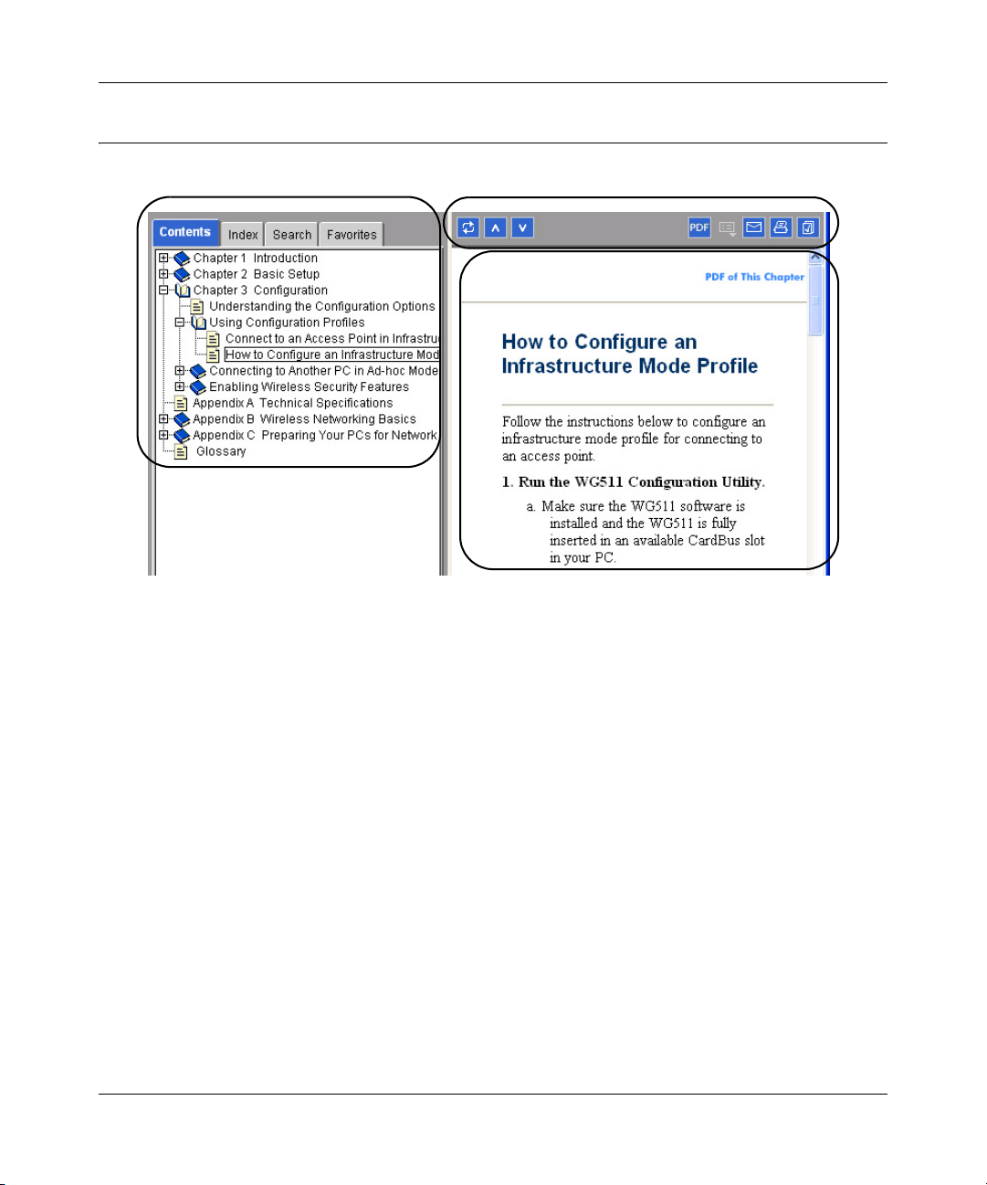
The HTML version of this manual includes these features.
1
Figure Preface -2: HTML version of this manual
1. Left pane. Use the left pane to view the Contents, Index, Search, and Favorites tabs.
To view the HTML version of the manual, you must have a version 4 or later browser with
Java or JavaScript enabled. To use the Favorites feature, your browser must be set to accept
cookies. You can record a list of favorite pages in the manual for easy later retrieval.
2
3
2. Toolbar buttons. Use the toolbar buttons across the top to navigate, print pages, and more.
–The Show in Contents button locates the currently displayed topic in the Contents tab.
– Previous/Next buttons display the topic that precedes or follows the current topic.
–The PDF button links to a PDF version of the full manual.
–The E-mail button enables you to send feedback by e-mail to Netgear support.
–The Print button prints the currently displayed topic. Using this button when a
step-by-step procedure is displayed will send the entire procedure to your printer--you do
not have to worry about specifying the correct range of pages.
–The Bookmark button bookmarks the currently displayed page in your browser.
3. Right pane. Use the right pane to view the contents of the manual. Also, each page of the
manual includes a “PDF of This Chapter” link at the top right which links to a PDF file
containing just the currently selected chapter of the manual.
About This Manual 3
M-10146-01
Page 16

Reference Manual for the Model FVS318 Broadband ProSafe VPN Firewall
How to Print this Manual
To print this manual you man choose one of the following several options, according to your
needs.
• A “How To ... ” Sequence of Steps in the HTML View. Use the Print button on the upper
right of the toolbar to print the currently displayed topic. Using this button when a step-by-step
procedure is displayed will send the entire procedure to your printer--you do not have to worry
about specifying the correct range of pages.
• A Chapter. Use the “PDF of This Chapter” link at the top right of any page.
– Click “PDF of This Chapter” link at the top right of any page in the chapter you want to
print. A new browser window opens showing the PDF version of the chapter you were
viewing.
– Click the print icon in the upper left of the window.
– Tip: If your printer supports printing two pages on a single sheet of paper, you can save
paper an printer ink by selecting this feature.
• The Full Manual. Use the PDF button in the toolbar at the top right of the browser window.
– Click PDF button. A new browser window opens showing the PDF version of the chapter
you were viewing.
– Click the print icon in the upper left of the window.
– Tip: If your printer supports printing two pages on a single sheet of paper, you can save
paper an printer ink by selecting this feature.
4 About This Manual
M-10146-01
Page 17

Chapter 2
Introduction
This chapter describes the features of the NETGEAR FVS318 Broadband ProSafe VPN Firewall .
About the FVS318
The FVS318 is a complete security solution that protects your network from attacks and
intrusions. Unlike simple Internet sharing routers that rely on Network Address Translation (NAT)
for security, the FVS318 uses Stateful Packet Inspection for Denial of Service (DoS) attack
protection and intrusion detection. The 8-port FVS318 provides highly reliable Internet access for
up to 253 users.
Key Features
The FVS318 offers the following features.
• Trustworthy VPN Communications Over the Internet
• A Powerful, True Firewall
• Content Filtering
• Auto Uplink Ethernet Connection
• Extensive Protocol Support
• Easy Installation and Management
• Helpful Status Indicators
A description of these key features follows.
Virtual Private Networking (VPN)
The FVS318 VPN Firewall provides a secure encrypted connection between your local area
network (LAN) and remote networks or clients. It includes the following VPN features:
Introduction 2-1
M-10146-01
Page 18

Reference Manual for the Model FVS318 Broadband ProSafe VPN Firewall
• Supports 8 VPN connections.
• Supports industry standard VPN protocols
The FVS318 VPN Firewall supports standard Manual or IKE keying methods, standard MD5
and SHA-1 authentication methods, and standard DES, 3DES, and AES encryption methods.
It is compatible with many other VPN products.
• Supports up to 256 bit AES encryption for maximum security.
A Powerful, True Firewall
Unlike simple Internet sharing NAT routers, the FVS318 is a true firewall, using stateful packet
inspection to defend against hacker attacks. Its firewall features include:
• Denial of Service (DoS) protection
Automatically detects and thwarts Denial of Service (DoS) attacks such as Ping of Death,
SYN Flood, LAND Attack and IP Spoofing.
• Blocks unwanted traffic from the Internet to your LAN.
• Blocks access from your LAN to Internet locations or services that you specify as off-limits.
• Logs security incidents
The FVS318 will log security events such as blocked incoming traffic, port scans, attacks, and
administrator logins. You can configure the firewall to email the log to you at specified
intervals. You can also configure the firewall to send immediate alert messages to your email
address or email pager whenever a significant event occurs.
Content Filtering
With its content filtering feature, the FVS318 prevents objectionable content from reaching your
PCs. The firewall allows you to control access to Internet content by screening for keywords
within Web addresses. You can configure the firewall to log and report attempts to access
objectionable Internet sites.
Configurable Auto Uplink™ Ethernet Connection
With its internal 8-port 10/100 switch, the FVS318 can connect to either a 10 Mbps standard
Ethernet network or a 100 Mbps Fast Ethernet network. The 10/100 Mbps LAN and WAN
interfaces are autosensing and capable of full-duplex or half-duplex operation.
2-2 Introduction
M-10146-01
Page 19

Reference Manual for the Model FVS318 Broadband ProSafe VPN Firewall
The firewall incorporates Auto UplinkTM technology. Each LOCAL Ethernet port will
automatically sense whether the Ethernet cable plugged into the port should have a ‘normal’
connection such as to a PC or an ‘uplink’ connection such as to a switch or hub. That port will then
configure itself to the correct configuration. This feature also eliminates the need to worry about
crossover cables, as Auto Uplink will accommodate either type of cable to make the right
connection.
Protocol Support
The FVS318 supports the Transmission Control Protocol/Internet Protocol (TCP/IP) and Routing
Information Protocol (RIP). Appendix B, “Networks, Routing, and Firewall Basics” provides
further information on TCP/IP.
• IP Address Sharing by NAT
The FVS318 allows several networked PCs to share an Internet account using only a single IP
address, which may be statically or dynamically assigned by your Internet service provider
(ISP). This technique, known as Network Address Translation (NAT), allows the use of an
inexpensive single-user ISP account.
• Automatic Configuration of Attached PCs by DHCP
The FVS318 dynamically assigns network configuration information, including IP, gateway,
and domain name server (DNS) addresses, to attached PCs on the LAN using the Dynamic
Host Configuration Protocol (DHCP). This feature greatly simplifies configuration of PCs on
your local network.
• DNS Proxy
When DHCP is enabled and no DNS addresses are specified, the firewall provides its own
address as a DNS server to the attached PCs. The firewall obtains actual DNS addresses from
the ISP during connection setup and forwards DNS requests from the LAN.
• PPP over Ethernet (PPPoE)
PPP over Ethernet is a protocol for connecting remote hosts to the Internet over a DSL
connection by simulating a dial-up connection. This feature eliminates the need to run a login
program such as EnterNet or WinPOET on your PC.
• PPTP login support for European ISPs, BigPond login for Telstra cable in Australia.
• Dynamic DNS
Dynamic DNS services allow remote users to find your network using a domain name when
your IP address is not permanently assigned. The firewall contains a client that can connect to
many popular Dynamic DNS services to register your dynamic IP address.
Introduction 2-3
M-10146-01
Page 20

Reference Manual for the Model FVS318 Broadband ProSafe VPN Firewall
Easy Installation and Management
You can install, configure, and operate the FVS318 within minutes after connecting it to the
network. The following features simplify installation and management tasks:
• Browser-based management
Browser-based configuration allows you to easily configure your firewall from almost any
type of personal computer, such as Windows, Macintosh, or Linux. A user-friendly Setup
Wizard is provided and online help documentation is built into the browser-based Web
Management Interface.
• Smart Wizard
The firewall automatically senses the type of Internet connection, asking you only for the
information required for your type of ISP account.
• Remote management
The firewall allows you to login to the Web Management Interface from a remote location via
the Internet. For security, you can limit remote management access to a specified remote IP
address or range of addresses, and you can choose a nonstandard port number.
• Diagnostic functions
The firewall incorporates built-in diagnostic functions such as Ping, DNS lookup, and remote
reboot. These functions allow you to test Internet connectivity and reboot the firewall. You can
use these diagnostic functions directly from the FVS318 when your are connected on the LAN
or when you are connected over the Internet via the remote management function.
• Visual monitoring
The firewall’s front panel LEDs provide an easy way to monitor its status and activity.
• Flash EPROM for firmware upgrade
• Regional support, including ISPs like Telstra DSL and BigPond or Deutsche Telekom.
2-4 Introduction
M-10146-01
Page 21
Reference Manual for the Model FVS318 Broadband ProSafe VPN Firewall
What’s in the Box?
The product package should contain the following items:
• FVS318 Broadband ProSafe VPN Firewall
•AC power adapter
• Category 5 (CAT5) Ethernet cable
• Resource CD (SW-10021-01), including:
— This manual
— Application Notes, Tools, and other helpful information
• Warranty and registration card
• Support information card
If any of the parts are incorrect, missing, or damaged, contact your NETGEAR dealer. Keep the
carton, including the original packing materials, in case you need to return the product for repair.
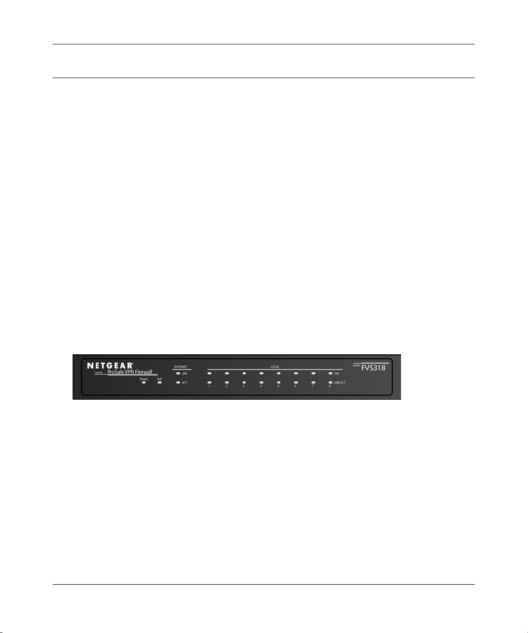
The Firewall’s Front Panel
The front panel of the FVS318 (Figure 2-1) contains status LEDs.
Figure 2-1: FVS318 Front Panel
You can use some of the LEDs to verify connections. Table 2-1 lists and describes each LED on
the front panel of the firewall.
Introduction 2-5
M-10146-01
Page 22
Reference Manual for the Model FVS318 Broadband ProSafe VPN Firewall
These LEDs are green when lit, except for the TEST LED, which is amber.
Table 2-1: LED Descriptions
Label Activity Description
POWER On Power is supplied to the firewall.
TEST On
Off
INTERNET and LOCAl
100 On/Blinking The port is operating at 100 Mbps.
LINK/ACT
(Link/Activity)
On/Blinking The port has detected a link with a connection and is operating at
The system is initializing.
The system is ready and running.
10 Mbps. Blinking indicates data transmission.
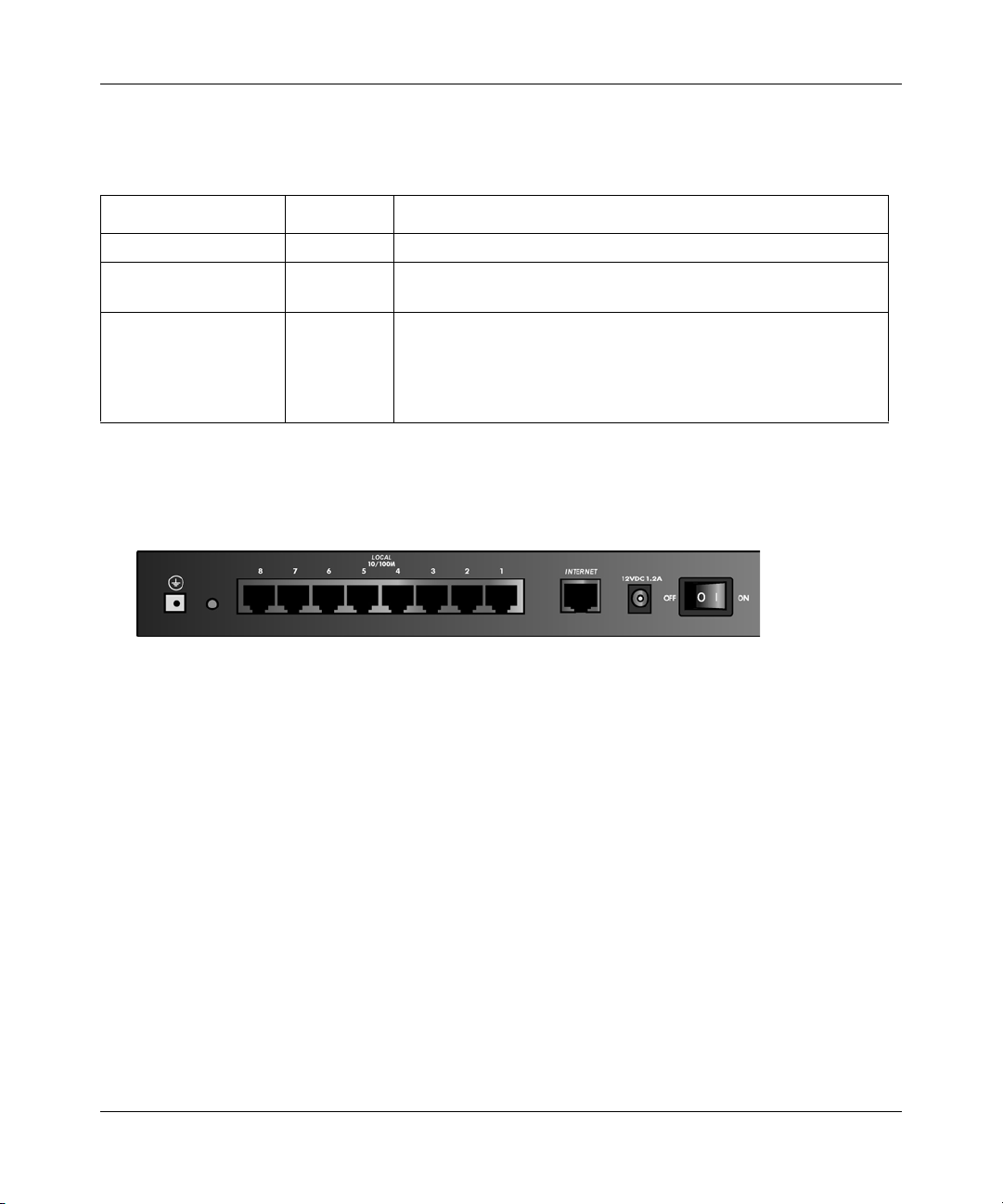
The Firewall’s Rear Panel
The rear panel of the FVS318 (Figure 2-2) contains the connections identified below.
Figure 2-2: FVS318 Rear Panel
Viewed from right to left, the rear panel contains the following elements:
• Ground connector.
• Factory Default Reset push button.
• Eight Local Ethernet RJ-45 ports for connecting the firewall to the local computers.
• Internet WAN Ethernet RJ-45 port for connecting the firewall to a cable or DSL modem.
• AC power adapter input.
• Power switch.
2-6 Introduction
M-10146-01
Page 23

Chapter 3
Connecting the Firewall to the Internet
This chapter describes how to set up the firewall on your Local Area Network (LAN), connect to
the Internet, perform basic configuration of your FVS318 Broadband ProSafe VPN Firewall using
the Setup Wizard, or how to manually configure your Internet connection.
What You Will Need Before You Begin
You need to prepare these three things before you can connect your firewall to the Internet:
1. A computer properly connected to the firewall as explained below.
2. Active Internet service such as that provided by a DSL or Cable modem account.
3. The Internet Service Provider (ISP) configuration information for your DSL or Cable modem
account.
LAN Hardware Requirements
The FVS318 VPN Firewall connects to your LAN via twisted-pair Ethernet cables.
Computer Requirements
To use the FVS318 VPN Firewall on your network, each computer must have an installed Ethernet
Network Interface Card (NIC) and an Ethernet cable. If the computer will connect to your network
at 100 Mbps, you must use a Category 5 (CAT5) cable such as the one provided with your firewall.
Cable or DSL Modem Requirement
The cable modem or DSL modem must provide a standard 10 Mbps 10BASE-T or 100 Mbps
100BASE-T Ethernet interface.
Connecting the Firewall to the Internet 3-1
M-10146-01
Page 24

Reference Manual for the Model FVS318 Broadband ProSafe VPN Firewall
LAN Configuration Requirements
For the initial connection to the Internet and configuration of your firewall, you will need to
connect a computer to the firewall which is set to automatically get its TCP/IP configuration from
the firewall via DHCP.
Note: Please refer to Appendix C, "Preparing Your Network" for assistance with DHCP
configuration.
Internet Configuration Requirements
Depending on how your ISP set up your Internet account, you will need one or more of these
configuration parameters to connect your firewall to the Internet:
• Host and Domain Names
• ISP Login Name and Password
• ISP Domain Name Server (DNS) Addresses
• Fixed or Static IP Address
Where Do I Get the Internet Configuration Parameters?
There are several ways you can gather the required Internet connection information.
• Your ISP should have provided you with all the information needed to connect to the Internet.
If you cannot locate this information, you can ask your ISP to provide it or you can try one of
the options below.
• If you have a computer already connected using the active Internet access account, you can
gather the configuration information from that computer.
• For Windows 95/98/ME, open the Network control panel, select the TCP/IP entry for the
Ethernet adapter, and click Properties.
• For Windows 2000/XP, open the Local Area Network Connection, select the TCP/IP entry
for the Ethernet adapter, and click Properties.
• For Macintosh computers, open the TCP/IP or Network control panel.
• You may also refer to the FVS318 Resource CD (SW-10021-01) for the NETGEAR Router
ISP Guide which provides Internet connection information for many ISPs.
Once you locate your Internet configuration parameters, you may want to record them on the page
below according to the instructions in “Worksheet for Recording Your Internet Connection
Information” on page 3-3.
3-2 Connecting the Firewall to the Internet
M-10146-01
Page 25

Reference Manual for the Model FVS318 Broadband ProSafe VPN Firewall
Worksheet for Recording Your Internet Connection Information
Print this page. Fill in the configuration parameters from your Internet Service Provider (ISP).
ISP Login Name: The login name and password are case sensitive and must be entered exactly as
given by your ISP. Some ISPs use your full e-mail address as the login name. The Service Name is
not required by all ISPs. If you connect using a login name and password, then fill in the
following:
Login Name: ______________________________
Password: ____________________________
Service Name: _____________________________
Fixed or Static IP Address: If you have a static IP address, record the following information. For
example, 169.254.141.148 could be a valid IP address.
Fixed or Static Internet IP Address: ______
. ______ . ______ . ______
Subnet Mask: ______ . ______ . ______ . ______
Gateway IP Address: ______ . ______ . ______ . ______
ISP DNS Server Addresses: If you were given DNS server addresses, fill in the following:
Primary DNS Server IP Address: ______
. ______ . ______ . ______
Secondary DNS Server IP Address: ______ . ______ . ______ . ______
Host and Domain Names: Some ISPs use a specific host or domain name like CCA7324-A or
home. If you haven’t been given host or domain names, you can use the following examples as a
guide:
• If your main e-mail account with your ISP is
aaa@yyy.com, then use aaa as your host name.
Your ISP might call this your account, user, host, computer, or system name.
• If your ISP’s mail server is
mail.xxx.yyy.com, then use xxx.yyy.com as the domain name.
ISP Host Name: _________________________
Connecting the Firewall to the Internet 3-3
ISP Domain Name: _______________________
M-10146-01
Page 26
Reference Manual for the Model FVS318 Broadband ProSafe VPN Firewall
How to Connect the FVS318 VPN Firewall
This section provides instructions for connecting the FVS318 Broadband ProSafe VPN Firewall
to your Local Area Network (LAN).
Note: The Resource CD included with your firewall contains an animated Installation Assistant to
help you through this procedure.
There are three steps to connecting your firewall:
1. Connect the firewall to your network
2. Log in to the firewall
3. Connect to the Internet
Follow the steps below to connect your firewall to your network. You can also refer to the
Resource CD included with your firewall which contains an animated Installation Assistant to help
you through this procedure.
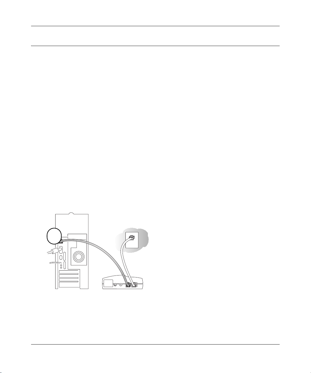
1. Connect the Firewall to Your LAN
a. Turn off your computer and Cable or DSL Modem.
b. Disconnect the Ethernet cable (A) from your computer which connects to your Cable or
DSL modem.
A
DSL modem
Figure 3-1: Disconnect the Cable or DSL Modem
3-4 Connecting the Firewall to the Internet
M-10146-01
Page 27
Reference Manual for the Model FVS318 Broadband ProSafe VPN Firewall
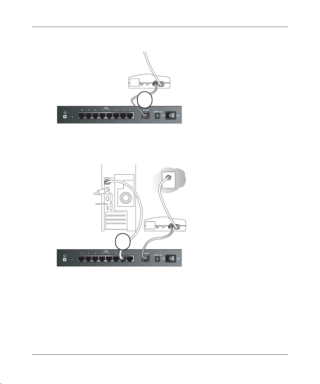
Connect the Ethernet cable (A) from your Cable or DSL modem to the FVS318’s Internet
c.
port.
Cable or
DSL modem
A
Figure 3-2: Connect the Cable or DSL Modem to the firewall
d.
Connect the Ethernet cable (B) which came with the firewall from a Local port on the
router to your computer.
Cable or
DSL modem
B
Figure 3-3: Connect the computers on your network to the firewall
Note: The FVS318 VPN Firewall incorporates Auto UplinkTM technology. Each LAN
Ethernet port will automatically sense whether the cable plugged into the port should have a
'normal' connection (e.g. connecting to a PC) or an 'uplink' connection (e.g. connecting to a
switch or hub). That port will then configure itself to the correct configuration. This feature
also eliminates the need to worry about crossover cables, as Auto Uplink will accommodate
either type of cable to make the right connection.
Connecting the Firewall to the Internet 3-5
M-10146-01
Page 28
Reference Manual for the Model FVS318 Broadband ProSafe VPN Firewall
Turn on the Cable or DSL modem and wait about 30 seconds for the lights to stop
e.
blinking.
2. Log in to the Firewall
Note: To connect to the firewall, your computer needs to be configured to obtain an IP address
automatically via DHCP. Please refer to Appendix C, "Preparing Your Network" for
instructions on how to do this.
a. Turn on the firewall and wait for the Test light to stop blinking.
b. Now, turn on your computer.
Note: If you usually run software to log in to your Internet connection, do not run that
software.
Now that the Cable or DSL Modem, firewall, and the computer are turned on, verify the
following:
• When power on the firewall was first turned on, the PWR light went on, the TEST light
turned on within a few seconds, and then went off after approximately 10 seconds.
• The firewall’s LOCAL LINK/ACT lights are lit for any computers that are connected to it.
• The firewall’s INTERNET LINK light is lit, indicating a link has been established to the
cable or DSL modem.
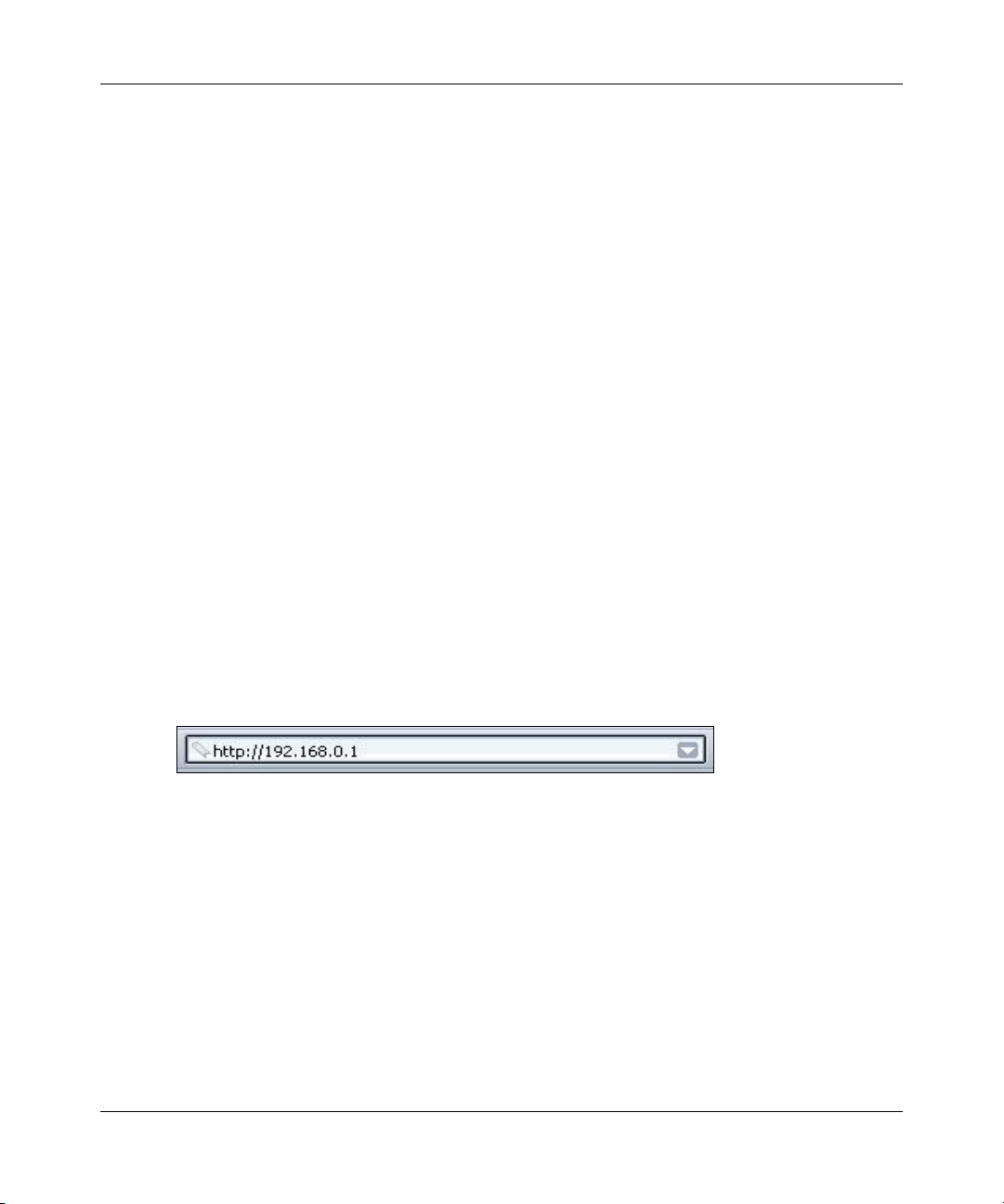
c. Next, use a browser like Internet Explorer or Netscape to log in to the firewall at its default
address of http://192.168.0.1.
Figure 3-4: Log in to the firewall
3-6 Connecting the Firewall to the Internet
M-10146-01
Page 29
Reference Manual for the Model FVS318 Broadband ProSafe VPN Firewall
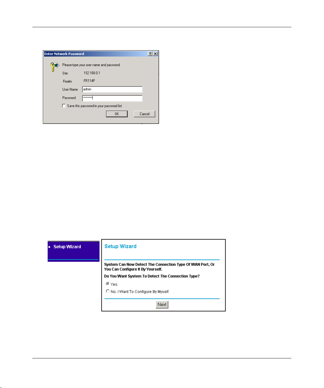
A login window opens as shown in Figure 3-5 below:
Figure 3-5: Login window
Note: If you were unable to connect to the firewall, please refer to “Basic Functions” on
page 8-1.
d. For security reasons, the firewall has its own user name and password. When prompted,
enter
admin for the firewall User Name and password for the firewall Password, both in
lower case letters.
Note: The user name and password are not the same as any user name or password you
may use to log in to your Internet connection.
3. Connect to the Internet
Figure 3-6: Setup Wizard
a.
You are now connected to the firewall. If you do not see the menu above, click the Setup
Wizard link on the upper left of the main menu. Click the Yes button in the Setup Wizard.
Connecting the Firewall to the Internet 3-7
M-10146-01
Page 30

Reference Manual for the Model FVS318 Broadband ProSafe VPN Firewall
Click Next and follow the steps in the Setup Wizard for inputting the configuration
b.
parameters from your ISP to connect to the Internet.
Note: If you choose not to use the Setup Wizard, you can manually configure your
Internet connection settings by following the procedure “How to Manually Configure
Your Internet Connection“ on page 3-13.
Unless your ISP automatically assigns your configuration automatically via DHCP, you
will need the configuration parameters from your ISP as you recorded them previously in
“Worksheet for Recording Your Internet Connection Information“ on page 3-3.
c. When the firewall successfully detects an active Ethernet connection with a broadband
modem, the firewall’s Internet LED goes on. The Setup Wizard reports which connection
type it discovered, and displays the appropriate configuration menu. If the Setup Wizard
finds no connection, you will be prompted to check the physical connection between your
firewall and the cable or DSL line.
d. The Setup Wizard will report the type of connection it finds. The options are:
• Connections which require a login using PPPoE, DHCP, or Static (Fixed) IP
connections. For PPTP or Telstra Bigpond Cable broadband, please refer to “How to
Manually Configure Your Internet Connection“ on page 3-13.
• Connections which use dynamic IP address assignment.
• Connections which use fixed IP address assignment.
The procedures for filling in the configuration menu for each type of connection follow
below.
3-8 Connecting the Firewall to the Internet
M-10146-01
Page 31

Reference Manual for the Model FVS318 Broadband ProSafe VPN Firewall
Wizard-Detected PPPoE Option
If the Setup Wizard determines that your Internet service account uses a login protocol such as
PPP over Ethernet (PPPoE), you will be directed to a menu like the PPPoE menu in Figure 3-7:
Figure 3-7: Setup Wizard menu for PPPoE login accounts
1.
Enter your Account Name (may also be called Host Name) and Domain Name. These
parameters may be necessary to access your ISP’s services such as mail or news servers. If you
leave the Domain Name field blank, the firewall will attempt to learn the domain
automatically from the ISP. If this is not successful, you may need to enter it manually.
2. Enter the PPPoE login user name and password provided by your ISP. These fields are case
sensitive. If you wish to change the login timeout, enter a new value in minutes. Entering zero
will keep the router connected to the Internet indefinitely.
Note: You will no longer need to launch the ISP’s login program on your PC in order to access
the Internet. When you start an Internet application, your firewall will automatically log you
in.
3. Domain Name Server (DNS) Address: If you know that your ISP does not automatically
transmit DNS addresses to the firewall during login, select “Use these DNS servers” and enter
the IP address of your ISP’s Primary DNS Server. If a Secondary DNS Server address is
available, enter it also.
Connecting the Firewall to the Internet 3-9
M-10146-01
Page 32

Reference Manual for the Model FVS318 Broadband ProSafe VPN Firewall
If you enter an address here, after you finish configuring the firewall, reboot your PCs so that
the settings take effect.
4. Click on Apply to save your settings.
5. Click on the Test button to test your Internet connection. If the NETGEAR website does not
appear within one minute, refer to Chapter 8, Troubleshooting”.
Wizard-Detected Dynamic IP Option
If the Setup Wizard determines that your Internet service account uses Dynamic IP assignment,
you will be directed to the menu shown in Figure 3-8 below:
Figure 3-8: Setup Wizard menu for Dynamic IP address
1.
Enter your Account Name (may also be called Host Name) and Domain Name. These
parameters may be necessary to access your ISP’s services such as mail or news servers. If you
leave the Domain Name field blank, the firewall will attempt to learn the domain
automatically from the ISP. If this is not successful, you may need to enter it manually.
2. If you know that your ISP does not automatically transmit DNS addresses to the firewall
during login, select “Use these DNS servers” and enter the IP address of your ISP’s Primary
DNS Server. If a Secondary DNS Server address is available, enter it also.
3-10 Connecting the Firewall to the Internet
M-10146-01
Page 33

Reference Manual for the Model FVS318 Broadband ProSafe VPN Firewall
A DNS server is a host on the Internet that translates Internet names (such as
www.netgear.com) to numeric IP addresses. Typically your ISP transfers the IP address of
one or two DNS servers to your firewall during login. If the ISP does not transfer an
address, you must obtain it from the ISP and enter it manually here. If you enter an address
here, you should reboot your PCs after configuring the firewall.
3. The Router’s MAC Address is the Ethernet MAC address that will be used by the firewall on
the Internet port.
If your ISP allows access from only one specific computer’s Ethernet MAC address, select
“Use this MAC address.” The firewall will then capture and use the MAC address of the
computer that you are now using. You must be using the one computer that is allowed by the
ISP. Otherwise, you can type in a MAC address.
Note: Some ISPs will register the Ethernet MAC address of the network interface card in your
PC when your account is first opened. They will then only accept traffic from the MAC
address of that PC. This feature allows your firewall to masquerade as that PC by using its
MAC address.
4. Click on Apply to save your settings.
5. Click on the Test button to test your Internet connection. If the NETGEAR website does not
appear within one minute, refer to Chapter 8, Troubleshooting”.
Wizard-Detected Fixed IP (Static) Option
If the Setup Wizard determines that your Internet service account uses Fixed IP assignment, you
will be directed to the menu shown in Figure 3-9 below:
Figure 3-9: Setup Wizard menu for Fixed IP address
Connecting the Firewall to the Internet 3-11
M-10146-01
Page 34

Reference Manual for the Model FVS318 Broadband ProSafe VPN Firewall
Enter your assigned IP Address, Subnet Mask, and the IP Address of your ISP’s gateway
1.
router. This information should have been provided to you by your ISP. You will need the
configuration parameters from your ISP you recorded in “Worksheet for Recording Your
Internet Connection Information” on page 3-3.
2. Enter the IP address of your ISP’s Primary DNS Server. If a Secondary DNS Server address is
available, enter it also.
A DNS servers are required to perform the function of translating an Internet name such as
www.netgear.com to a numeric IP address. For a fixed IP address configuration, you must
obtain DNS server addresses from your ISP and enter them manually here. You should reboot
your PCs after configuring the firewall for these settings to take effect.
3. Click on Apply to save the settings.
4. Click on the Test button to test your Internet connection. If the NETGEAR website does not
appear within one minute, refer to Chapter 8, Troubleshooting.
Testing Your Internet Connection
After completing the Internet connection configuration, your can test your Internet connection.
Log in to the firewall, then, from the Setup Basic Settings link, click on the Test button. If the
NETGEAR website does not appear within one minute, refer to Chapter 8, Troubleshooting.
Your firewall is now configured to provide Internet access for your network. Your firewall
automatically connects to the Internet when one of your computers requires access. It is not
necessary to run a dialer or login application such as Dial-Up Networking or Enternet to connect,
log in, or disconnect. These functions are performed by the firewall as needed.
To access the Internet from any computer connected to your firewall, launch a browser such as
Microsoft Internet Explorer or Netscape Navigator. You should see the firewall’s Internet LED
blink, indicating communication to the ISP. The browser should begin to display a Web page.
The following chapters describe how to configure the Advanced features of your firewall, and how
to troubleshoot problems that may occur.
3-12 Connecting the Firewall to the Internet
M-10146-01
Page 35

Reference Manual for the Model FVS318 Broadband ProSafe VPN Firewall
How to Manually Configure Your Internet Connection
You can manually configure your firewall using the menu below, or you can allow the Setup
Wizard to determine your configuration as described in the previous section.
ISP Does Not Require Login
ISP Does Require Login
Figure 3-10: Browser-based configuration Basic Settings menu
You can manually configure the firewall using the Basic Settings menu shown in Figure 3-10
using these steps:
1. Log in to the firewall at its default address of http://192.168.0.1 using a browser like Internet
®
Explorer or Netscape
Connecting the Firewall to the Internet 3-13
Navigator.
M-10146-01
Page 36

Reference Manual for the Model FVS318 Broadband ProSafe VPN Firewall
Click the Basic Settings link under the Setup section of the main menu.
2.
3. If your Internet connection does not require a login, click No at the top of the Basic Settings
menu and fill in the settings according to the instructions below. If your Internet connection
does require a login, click Yes, and skip to step 4.
a. Enter your Account Name (may also be called Host Name) and Domain Name.
These parameters may be necessary to access your ISP’s services such as mail or news
servers.
b. Internet IP Address:
If your ISP has assigned you a permanent, fixed (static) IP address for your PC, select
“Use static IP address”. Enter the IP address that your ISP assigned. Also enter the
netmask and the Gateway IP address. The Gateway is the ISP’s router to which your
firewall will connect.
c. Domain Name Server (DNS) Address:
If you know that your ISP does not automatically transmit DNS addresses to the firewall
during login, select “Use these DNS servers” and enter the IP address of your ISP’s
Primary DNS Server. If a Secondary DNS Server address is available, enter it also.
Note: After completing the DNS configuration, restart the computers on your network so
that these settings take effect.
d. Gateway’s MAC Address:
This section determines the Ethernet MAC address that will be used by the firewall on the
Internet port. Some ISPs will register the Ethernet MAC address of the network interface
card in your PC when your account is first opened. They will then only accept traffic from
the MAC address of that PC. This feature allows your firewall to masquerade as that PC
by “cloning” its MAC address.
To change the MAC address, select “Use this Computer’s MAC address.” The firewall
will then capture and use the MAC address of the PC that you are now using. You must be
using the one PC that is allowed by the ISP. Or, select “Use this MAC address” and enter
it.
e. Click Apply to save your settings.
4. If your Internet connection does require a login, fill in the settings according to the instructions
below. Select Yes if you normally must launch a login program such as Enternet or WinPOET
in order to access the Internet.
Note: After you finish setting up your firewall, you will no longer need to launch the ISP’s
login program on your PC in order to access the Internet. When you start an Internet
application, your firewall will automatically log you in.
3-14 Connecting the Firewall to the Internet
M-10146-01
Page 37

Reference Manual for the Model FVS318 Broadband ProSafe VPN Firewall
Connections which require a login using protocols such as PPPoE, PPTP, Telstra Bigpond
a.
Cable broadband connections. Select your Internet service provider from the drop-down
list.
Figure 3-11: Basic Settings ISP list
b.
The screen will change according to the ISP settings requirements of the ISP you select.
c. Fill in the parameters for your ISP according to the Wizard-detected procedures starting on
page 3-7.
d. Click Apply to save your settings.
Connecting the Firewall to the Internet 3-15
M-10146-01
Page 38

Reference Manual for the Model FVS318 Broadband ProSafe VPN Firewall
3-16 Connecting the Firewall to the Internet
M-10146-01
Page 39

Chapter 4
Protecting Your Network
This chapter describes how to use the basic firewall features of the FVS318 Broadband ProSafe
VPN Firewall to protect your network.
Protecting Access to Your FVS318 VPN Firewall
For security reasons, the firewall has its own user name and password. Also, after a period of
inactivity for a set length of time, the administrator login will automatically disconnect. When
prompted, enter
can use procedures below to change the firewall's password and the amount of time for the
administrator’s login timeout.
Note: The user name and password are not the same as any user name or password your may use
to log in to your Internet connection.
NETGEAR recommends that you change this password to a more secure password. The ideal
password should contain no dictionary words from any language, and should be a mixture of both
upper and lower case letters, numbers, and symbols. Your password can be up to 30 characters.
admin for the firewall User Name and password for the firewall Password. You
How to Change the Built-In Password
1. Log in to the firewall at its default LAN address of http://192.168.0.1 with its default User
Name of
LAN address you have chosen for the firewall.
Protecting Your Network 4-1
admin, default password of password, or using whatever User Name, Password and
M-10146-01
Page 40

Reference Manual for the Model FVS318 Broadband ProSafe VPN Firewall
From the Main Menu of the browser interface, under the Maintenance heading, select Set
2.
Password to bring up the menu shown in Figure 4-1.
Figure 4-1: Set Password menu
3.
To change the password, first enter the old password, and then enter the new password twice.
4. Click Apply to save your changes.
Note: After changing the password, you will be required to log in again to continue the
configuration.
If you have backed up the firewall settings previously, you should do a new
backup so that the saved settings file includes the new password.
How to Change the Administrator Login Timeout
For security, the administrator's login to the firewall configuration will timeout after a period of
inactivity. To change the login timeout period:
1. In the Set Password menu, type a number in ‘Administrator login times out’ field.The
suggested default value is 5 minutes.
2. Click Apply to save your changes or click Cancel to keep the current period.
Using Basic Firewall Services
Basic firewall services you can configure include access blocking and scheduling of firewall
security. These topics are presented below.
4-2 Protecting Your Network
M-10146-01
Page 41

Reference Manual for the Model FVS318 Broadband ProSafe VPN Firewall
The firewall provides a variety of options for blocking Internet based content and
communications services. With its content filtering feature, the FVS318 VPN Firewall prevents
objectionable content from reaching your PCs. The FVS318 allows you to control access to
Internet content by screening for keywords within Web addresses. Key content filtering options
include:
• Blocks access from your LAN to Internet locations that you specify as off-limits.
• ActiveX, Java, cookie, and web proxy filtering.
– ActiveX and Java programs can be embedded in websites, and will be executed by your
computer. These programs may sometimes include malicious content.
– Cookies are small files that a website can store on your computer to track your activity.
Some cookies can be helpful, but some may compromise your privacy.
– Web proxies are computers on the Internet that act as relays for browsing. A web proxy
can be used to bypass your web blocking methods.
• Keyword blocking of newsgroup names.
• Outbound Services Blocking limits access from your LAN to Internet locations or services
that you specify as off-limits.
• Denial of Service (DoS) protection. Automatically detects and thwarts Denial of Service
(DoS) attacks such as Ping of Death, SYN Flood, LAND Attack and IP Spoofing.
• Blocks unwanted traffic from the Internet to your LAN.
The section below explains how to configure your
firewall to perform these functions.
How to Block Keywords and Sites
The FVS318 VPN Firewall allows you to restrict access to Internet content based on functions
such as Java or Cookies, Web addresses and Web address keywords.
1. Log in to the firewall at its default LAN address of http://192.168.0.1 with its default User
Name of
LAN address you have chosen for the firewall.
Protecting Your Network 4-3
admin, default password of password, or using whatever User Name, Password and
M-10146-01
Page 42

Reference Manual for the Model FVS318 Broadband ProSafe VPN Firewall
Click on the Block Sites link of the Security menu.
2.
Figure 4-2: Block Sites menu
3.
To block ActiveX, Java, Cookies, or Web Proxy functions for all Internet sites, click the check
box next to the function and then click Apply. Be aware that blocking these functions can
cause some web sites to not load or function properly.
4. To enable keyword blocking, check “Turn keyword blocking on”, enter a keyword or domain
in the Keyword box, click Add Keyword, then click Apply. Each keyword can be up to 256
characters long.
Some examples of Keyword application follow:
• If the keyword “XXX” is specified, the URL <http://www.badstuff.com/xxx.html> is
blocked, as is the newsgroup alt.pictures.xxx.
• If the keyword “.com” is specified, only websites with other domain suffixes (such as .edu
or .gov) can be viewed.
• Enter the keyword “.” to block all Internet browsing access.
4-4 Protecting Your Network
M-10146-01
Page 43

Reference Manual for the Model FVS318 Broadband ProSafe VPN Firewall
Up to 32 entries are supported in the Keyword list.
5. To delete a keyword or domain, select it from the list, click Delete Keyword, then click Apply.
6. To specify a Trusted User, enter that PC’s IP address in the Trusted User box and click Apply.
You may specify one Trusted User, which is a PC that will be exempt from blocking and
logging. Since the Trusted User will be identified by an IP address, you should configure that
PC with a fixed IP address.
7. Click Apply to save your settings.
How to Block or Allow Services
Services are functions performed by server computers at the request of client computers. For
example, Web servers serve web pages, time servers serve time and date information, and game
hosts serve data about other players’ moves. When a computer on the Internet sends a request for
service to a server computer, the requested service is identified by a service or port number. This
number appears as the destination port number in the transmitted IP packets. For example, a packet
that is sent with destination port number 80 is an HTTP (Web server) request.
1. Log in to the firewall at its default LAN address of http://192.168.0.1 with its default User
Name of
LAN address you have chosen for the firewall.
admin, default password of password, or using whatever User Name, Password and
2. Click on the Services link of the Security menu to display the Services menu shown in
Figure 4-5:
Figure 4-3: Services menu
• To create a new entry, click the Add button.
Protecting Your Network 4-5
M-10146-01
Page 44

Reference Manual for the Model FVS318 Broadband ProSafe VPN Firewall
• To edit an existing entry, select its button on the left side of the table and click Edit.
• To delete an existing entry, select its button on the left side of the table and click Delete.
3. Modify the menu shown below for defining or editing a service.
Figure 4-4: Add Services menu
The parameters are:
•Service.
From this list, select the application or service to be allowed or blocked. The list already
displays many common services, but you are not limited to these choices. Use the Add
Services menu to add any additional services or applications that do not already appear.
• Action.
Choose how you would like this type of traffic to be handled. Allow always is the default
and you can block always or choose to block or allow according to the schedule you have
defined in the Schedule menu.
• LAN Users Address.
Specify traffic originating on the LAN (outbound), and choose whether you would like the
traffic to be restricted by source IP address. You can select Any, a Single address, or a
Range. If you select a range of addresses, enter the range in the start and finish boxes. If
you select a single address, enter it in the start box.
•Log.
4-6 Protecting Your Network
M-10146-01
Page 45

Reference Manual for the Model FVS318 Broadband ProSafe VPN Firewall
You can select whether the traffic will be logged. The choices are:
• Never - no log entries will be made for this service.
• Always - any traffic for this service type will be logged.
• Match - traffic of this type which matches the parameters and action will be logged.
• Not match - traffic of this type which does not match the parameters and action will be
logged.
4. Click Apply to save your changes.
How to Add to the List of Services
The service numbers for many common protocols are defined by the Internet Engineering Task
Force (IETF) and published in RFC1700, “Assigned Numbers.” Service numbers for other
applications are typically chosen from the range 1024 to 65535 by the authors of the application.
Although the FVS318 already holds a list of many service port numbers, you are not limited to
these choices. Use the procedure below to create your own service definitions.
1. Log in to the firewall at its default LAN address of http://192.168.0.1 with its default User
Name of
LAN address you have chosen for the firewall.
admin, default password of password, or using whatever User Name, Password and
Protecting Your Network 4-7
M-10146-01
Page 46

Reference Manual for the Model FVS318 Broadband ProSafe VPN Firewall
Click on the Add Service link of the Security menu to display the Services list shown in
2.
Figure 4-5:
Figure 4-5: Services table
• To create a new entry, click the Add Custom Service button.
• To edit an existing entry, select its button on the left side of the table and click Edit.
• To delete an existing entry, select its button on the left side of the table and click Delete.
4-8 Protecting Your Network
M-10146-01
Page 47

Reference Manual for the Model FVS318 Broadband ProSafe VPN Firewall
Modify the menu shown below for defining or editing a service.
3.
Figure 4-6: Add Services menu
The parameters are:
• Name.
This name will appear in the drop-down list services to be allowed or blocked in the Add
Block Service menu as seen in Figure 4-4 above.
•Type.
Choose the type of traffic to be handled: TCP/UDP; TCP; or UDP.
• Start Port.
Specify the starting port number here. If you select a single port, enter it in both the start
and Finish boxes.
• Finish Port.
Specify the ending port number here. If you select a single port, enter it in both the start
and Finish boxes.
4. Click Apply to save your changes.
Protecting Your Network 4-9
M-10146-01
Page 48

Reference Manual for the Model FVS318 Broadband ProSafe VPN Firewall
Setting Times and Scheduling Firewall Services
The FVS318 VPN Firewall uses the Network Time Protocol (NTP) to obtain the current time and
date from one of several Network Time Servers on the Internet. In order to localize the time for
your log entries, you must select your Time Zone from the list.
How to Set Your Time Zone
In order to localize the time for your log entries, you must specify your Time Zone:
1. Log in to the firewall at its default LAN address of http://192.168.0.1 with its default User
Name of
LAN address you have chosen for the firewall.
2. Click on the Schedule link of the Security menu to display menu shown below.
admin, default password of password, or using whatever User Name, Password and
Figure 4-7: Schedule Services menu
4-10 Protecting Your Network
M-10146-01
Page 49

Reference Manual for the Model FVS318 Broadband ProSafe VPN Firewall
Select your Time Zone. This setting will be used for the blocking schedule according to your
3.
local time zone and for time-stamping log entries. Check the Daylight Savings Time box if
your time zone is currently in daylight savings time.
Note: If your region uses Daylight Savings Time, you must manually check Adjust for
Daylight Savings Time on the first day of Daylight Savings Time, and uncheck it at the end.
Enabling Daylight Savings Time will cause one hour to be added to the standard time.
4. The firewall has a list of publicly available NTP servers. If you would prefer to use a particular
NTP server as the primary server, enter its IP address under Use this NTP Server.
5. Click Apply to save your settings.
How to Schedule Firewall Services
If you enabled services blocking in the Block Services menu or Port forwarding in the Ports menu,
you can set up a schedule for when blocking occurs or when access isn't restricted.
1. Log in to the firewall at its default LAN address of http://192.168.0.1 with its default User
Name of
LAN address you have chosen for the firewall.
admin, default password of password, or using whatever User Name, Password and
2. Click on the Schedule link of the Security menu to display menu shown above in the Schedule
Services menu.
3. To block Internet services based on a schedule, select Every Day or select one or more days. If
you want to limit access completely for the selected days, select All Day. Otherwise, to limit
access during certain times for the selected days, enter Start Blocking and End Blocking times.
Note: Enter the values as 24-hour time. For example, 10:30 am would be 10 hours and 30
minutes and 10:30 pm would be 22 hours and 30 minutes.
4. Click Apply to save your changes.
Protecting Your Network 4-11
M-10146-01
Page 50

Reference Manual for the Model FVS318 Broadband ProSafe VPN Firewall
4-12 Protecting Your Network
M-10146-01
Page 51

Chapter 5
Advanced WAN and LAN Configuration
This chapter describes how to configure the advanced features of your FVS318 Broadband
ProSafe VPN Firewall .
Configuring Advanced WAN Settings
The FVS318 Broadband ProSafe VPN Firewall provides a variety of advanced features, such as:
• Setting up a Demilitarized Zone (DMZ) Server.
• Port forwarding for enabling networked gaming and various Internet services.
• Universal Plug and Play (UPnP) support to make accessing various games and services over
easier.
• The flexibility of configuring your LAN TCP/IP settings.
These features are discussed below.
Setting Up A Default DMZ Server
The Default DMZ Server feature is helpful when using some online games and videoconferencing
applications that are incompatible with NAT. The Firewall is programmed to recognize some of
these applications and to work properly with them, but there are other applications that may not
function well. In some cases, one local PC can run the application properly if that PC’s IP address
is entered as the Default DMZ Server
Note: When a computer is designated as the Default DMZ Server, it loses much of the
protection of the firewall, and is exposed to many exploits from the Internet. If
compromised, the computer can be used to attack your network.
Advanced WAN and LAN Configuration 5-1
M-10146-01
Page 52

Reference Manual for the Model FVS318 Broadband ProSafe VPN Firewall
Incoming traffic from the Internet is normally discarded by the Firewall unless the traffic is a
response to one of your local computers or a service that you have configured in the Ports menu.
Instead of discarding this traffic, you can have it forwarded to one computer on your network. This
computer is called the Default DMZ Server.
To assign a computer or server to be a Default DMZ server:
1. Click Default DMZ Server.
2. Type the IP address for that server.
3. Click Apply.
Enabling Access to Local Servers Through a FVS318
Although the Firewall causes your entire local network to appear as a single machine to the
Internet, you can make local servers for different services (for example, FTP or HTTP) visible and
available to the Internet. This is done using the Ports menu.
When a remote computer on the Internet wants to access a service at your IP address, the requested
service is identified by a port number in the incoming IP packets. For example, a packet that is sent
to the external IP address of your Firewall and destined for port number 80 is an HTTP (Web
server) request. Many service port numbers are already defined in a Services list in the Ports menu,
although you are not limited to these choices. See IETF RFC1700, “Assigned Numbers,” for port
numbers for common protocols. Use the Ports menu to configure the Firewall to forward incoming
traffic to IP addresses on your local network based on the port number.
Note: Some residential broadband ISP accounts do not allow you to run any server
processes (such as a Web or FTP server) from your location. Your ISP may periodically
check for servers and may suspend your account if it discovers any active services at
your location. If you are unsure, refer to the Acceptable Use Policy of your ISP.
Remember that port forwarding opens holes in your firewall. Only enable those ports that are
necessary for your network.
How to Configure Port Forwarding to Local Servers
1. Log in to the Firewall at its default LAN address of http://192.168.0.1 with its default User
Name of
LAN address you have chosen for the Firewall.
5-2 Advanced WAN and LAN Configuration
admin, default password of password, or using whatever User Name, Password and
M-10146-01
Page 53

Reference Manual for the Model FVS318 Broadband ProSafe VPN Firewall
From the Main Menu of the browser interface, under Advanced, click on Ports to view the port
2.
forwarding menu, shown in Figure 5-1
Figure 5-1: Port Forwarding Menu
Respond to Ping on Internet WAN Port
If you want the Firewall to respond to a 'ping' from the Internet, click the ‘Respond to Ping on
Internet WAN Port’ check box. This should only be used as a diagnostic tool, since it allows your
Firewall to be discovered. Don't check this box unless you have a specific reason to do so.
How to Support Internet Services, Applications, or Games
Before starting, you'll need to determine which type of service, application or game you'll provide
and the IP address of the computer that will provide each service. Be sure the computer’s IP
address never changes. If the computers on your local network are assigned their IP addresses by
the Firewall (by DHCP), use the Reserved IP address feature in the LAN IP menu to keep the
computer’s IP address constant.
To set up a computer or server to be accessible to the Internet for an Internet service:
1. Click Add to bring up the Add Port menu.
2. From the Services list, select the Internet service, application or game you want to host. If the
service, application or game does not appear in the Services list, define it using the Add
Service menu as described on “How to Block or Allow Services“ on page 4-5.
3. Type the IP address of the computer in the Server IP Address box.
4. Click Apply.
Note: You may forward more than one type of service to a single computer or server.
Advanced WAN and LAN Configuration 5-3
M-10146-01
Page 54

Reference Manual for the Model FVS318 Broadband ProSafe VPN Firewall
How to Clear a Port Assignment
To edit or eliminate a port assignment entry:
1. Click the button next to that port in the table.
2. Click Delete or Edit.
3. Click Apply.
Local Web and FTP Server Example
If a local PC with a private IP address of 192.168.0.33 acts as a Web and FTP server, configure the
Ports menu to forward HTTP (port 80) and FTP (port 21) to local address 192.168.0.33
In order for a remote user to access this server from the Internet, the remote user must know the IP
address that has been assigned by your ISP. If this address is 172.16.1.23, for example, an Internet
user can access your Web server by directing the browser to http://172.16.1.23. The assigned IP
address can be found in the Maintenance Status Menu, where it is shown as the WAN IP Address.
Some considerations for this application are:
• If your account’s IP address is assigned dynamically by your ISP, the IP address may change
periodically as the DHCP lease expires. In this case, you can also consider using a dynamic
DNS service provider which enables your FVS318 to use a Fully Qualified Domain Name as
its Internet address. Dynamic DNS services allow remote users to find your network using a
domain name when your IP address is not permanently assigned.
• If the IP address of the local PC is assigned by DHCP, it may change when the PC is rebooted.
To avoid this, use the Reserved IP address feature in the LAN IP menu to keep the PC’s IP
address constant.
• Local PCs must access the local server using the PCs’ local LAN address (192.168.0.33 in this
example). Attempts by local PCs to access the server using the external IP address
(172.16.1.23 in this example) will fail.
How to Set Up Computers for Half Life, KALI or Quake III
To set up an additional computer to play Half Life, KALI or Quake III:
1. Click Add to add a new Port entry to the table.
2. Select the game again from the Services list.
5-4 Advanced WAN and LAN Configuration
M-10146-01
Page 55

Reference Manual for the Model FVS318 Broadband ProSafe VPN Firewall
Change the beginning port number in the Start Port box.
3.
For these games, use the supplied number in the default listing and add +1 for each additional
computer. For example, if you've already configured one computer to play Hexen II (using
port 26900), the second computer's port number would be 26901, and the third computer
would be 26902.
4. Type the same port number in the End Port box that you typed in the Start Port box.
5. Type the IP address of the additional computer in the Server IP Address box.
6. Click Apply.
Working with LAN IP Settings
The LAN IP Setup menu allows configuration of LAN IP services such as UPnP, DHCP and RIP.
These features can be found under the Advanced heading in the Main Menu of the browser
interface.
What Does UPnP Support Do for Me?
With the FVS318 Broadband ProSafe VPN Firewall , you can enable Microsoft UPnP for Network
Address Translation (NAT) traversal. The scenarios that UPnP-enabled NAT traversal helps ensure
include: multi-player gaming, peer-to-peer connections, real time communications, and remote assistance
NAT is a standard used to allow multiple computers or devices on a private network using private
address ranges such as 10.0.x.x, 192.168.x.x, 172.x.x.x to share a single IP address. NAT is used in
gateway devices such as FVS318 VPN Firewall that form the boundary between the public
Internet and the private LAN. As IP packets from the private LAN traverse the gateway, NAT
translates a private IP address and port number to a public IP address and port number, tracking
those translations to keep individual sessions intact.
NAT can interfere with many of the new PC and home networking experiences, such as
multi-player games, real time communications, and other peer-to-peer services, that people
increasingly want to use in their homes or small businesses. These applications will not work if
they a use private address on the public Internet or require simultaneous use of the same port
number. Applications must use a public address, and, for each session, a unique port number.
UPnP NAT Traversal can automatically solve many of the problems that NAT imposes on
applications.
Advanced WAN and LAN Configuration 5-5
M-10146-01
Page 56

Reference Manual for the Model FVS318 Broadband ProSafe VPN Firewall
How to Enable UPnP
1. Log in to the Firewall at its default LAN address of http://192.168.0.1 with its default User
Name of
LAN address you have chosen for the Firewall.
2. Click the LAN IP Setup link from the Advanced section of the main menu to display the menu
shown in Figure 5-3
admin, default password of password, or using whatever User Name, Password and
Figure 5-2: Enabling UPnP via the LAN IP Setup Menu
3.
Click the Enable UPnP check box.
4. Click Apply to save your changes.
5-6 Advanced WAN and LAN Configuration
M-10146-01
Page 57

Reference Manual for the Model FVS318 Broadband ProSafe VPN Firewall
Understanding LAN TCP/IP Setup Parameters
The Firewall is shipped preconfigured to use private IP addresses on the LAN side, and to act as a
DHCP server. The Firewall’s default LAN IP configuration is:
• LAN IP addresses—192.168.0.1
• Subnet mask—255.255.255.0
These addresses are part of the IETF-designated private address range for use in private networks,
and should be suitable in most applications. If your network has a requirement to use a different IP
addressing scheme, you can make those changes in this menu.
The LAN TCP/IP Setup parameters are:
• IP Address
This is the LAN IP address of the Firewall.
• IP Subnet Mask
This is the LAN Subnet Mask of the Firewall. Combined with the IP address, the IP Subnet
Mask allows a device to know which other addresses are local to it, and which must be reached
through a gateway or router.
• RIP Direction
RIP (Router Information Protocol) allows a router to exchange routing information with other
routers. The RIP Direction selection controls how the Firewall sends and receives RIP packets.
Both is the default.
— When set to Both or Out Only, the Firewall will broadcast its routing table periodically.
— When set to Both or In Only, it will incorporate the RIP information that it receives.
— When set to None, it will not send any RIP packets and will ignore any RIP packets
received.
• RIP Version
This controls the format and the broadcasting method of the RIP packets that the router sends.
It recognizes both formats when receiving. By default, this is set for RIP-1.
— RIP-1 is universally supported. RIP-1 is probably adequate for most networks, unless you
have an unusual network setup.
— RIP-2 carries more information. Both RIP-2B and RIP-2M send the routing data in RIP-2
format. RIP-2B uses subnet broadcasting. RIP-2M uses multicasting.
Advanced WAN and LAN Configuration 5-7
M-10146-01
Page 58

Reference Manual for the Model FVS318 Broadband ProSafe VPN Firewall
Note: If you change the LAN IP address of the Firewall while connected through the
browser, you will be disconnected. You must then open a new connection to the new IP
address and log in again.
Setting the MTU Size
The normal MTU (Maximum Transmit Unit) value for most Ethernet networks is 1500 Bytes. For
some ISPs, particularly some using PPPoE, your router will need to automatically reduce the
MTU. If the resulting setting is not suitable, you may need to reduce the MTU manually. This is
rarely required, and should not be done unless you are sure it is necessary for your ISP connection.
Any packets sent through the Firewall that are larger than the configured MTU size will be
repackaged into smaller packets to meet the MTU requirement. To change the MTU size:
1. Under MTU Size, select Custom.
2. Enter a new size between 64 and 1500.
3. Click Apply to save the new configuration.
Using the Router as a DHCP Server
By default, the Firewall will function as a DHCP (Dynamic Host Configuration Protocol) server,
allowing it to assign IP, DNS server, and default gateway addresses to all computers connected to
the router's LAN. The assigned default gateway address is the LAN address of the Firewall. IP
addresses will be assigned to the attached PCs from a pool of addresses specified in this menu.
Each pool address is tested before it is assigned to avoid duplicate addresses on the LAN.
For most applications, the default DHCP and TCP/IP settings of the Firewall are satisfactory. See
“IP Configuration by DHCP” on page B-10 for an explanation of DHCP and information about
how to assign IP addresses for your network.
If another device on your network will be the DHCP server, or if you will manually configure the
network settings of all of your computers, clear the ‘Use router as DHCP server’ check box.
Otherwise, leave it checked.
Specify the pool of IP addresses to be assigned by setting the Starting IP Address and Ending IP
Address. These addresses should be part of the same IP address subnet as the Firewall’s LAN IP
address. Using the default addressing scheme, you should define a range between 192.168.0.2 and
192.168.0.253, although you may wish to save part of the range for devices with fixed addresses.
5-8 Advanced WAN and LAN Configuration
M-10146-01
Page 59

Reference Manual for the Model FVS318 Broadband ProSafe VPN Firewall
The Firewall will deliver the following parameters to any LAN device that requests DHCP:
• An IP Address from the range you have defined
• Subnet Mask
• Gateway IP Address is the Firewall’s LAN IP address
• Primary DNS Server, if you entered a Primary DNS address in the Basic Settings menu;
otherwise, the Firewall’s LAN IP address
• Secondary DNS Server, if you entered a Secondary DNS address in the Basic Settings menu
• WINS Server, s
hort for Windows Internet Naming Service, determines the IP address
associated with a particular Windows computer. A WINS server records and reports a
list of names and IP address of Windows PCs on its local network. If you connect to a
remote network that contains a WINS server, enter the server’s IP address here. This
allows your PCs to browse the network using the Network Neighborhood feature of
Windows.
How to Specify Reserved IP Addresses
When you specify a reserved IP address for a PC on the LAN, that PC will always receive the
same IP address each time it access the Firewall’s DHCP server. Reserved IP addresses should be
assigned to servers that require permanent IP settings.
To reserve an IP address:
1. Click the Add button.
2. In the IP Address box, type the IP address to assign to the PC or server.
Choose an IP address from the router’s LAN subnet, such as 192.168.0.X.
3. Type the MAC Address of the PC or server.
Tip: If the PC is already present on your network, you can copy its MAC address from the
Attached Devices menu and paste it here.
4. Click Apply to enter the reserved address into the table.
Note: Reboot the PC to force a DHCP release and renew. Reserved addresses will not be
assigned until the next time the PC contacts the router's DHCP server.
To edit or delete a reserved address entry:
1. Click the button next to the reserved address you want to edit or delete.
2. Click Edit or Delete.
Advanced WAN and LAN Configuration 5-9
M-10146-01
Page 60

Reference Manual for the Model FVS318 Broadband ProSafe VPN Firewall
How to Configure LAN TCP/IP Settings
1. Log in to the Firewall at its default LAN address of http://192.168.0.1 with its default User
Name of
LAN address you have chosen for the Firewall.
2. From the Main Menu, under Advanced, click the LAN IP Setup link to view the menu, shown
in Figure 5-3
admin, default password of password, or using whatever User Name, Password and
Figure 5-3: LAN IP Setup Menu
3.
Enter the TCP/IP, MTU, or DHCP parameters.
4. Click Apply to save your changes.
5-10 Advanced WAN and LAN Configuration
M-10146-01
Page 61

Reference Manual for the Model FVS318 Broadband ProSafe VPN Firewall
How to Configure Dynamic DNS
If your network has a permanently assigned IP address, you can register a domain name and have
that name linked with your IP address by public Domain Name Servers (DNS). However, if your
Internet account uses a dynamically assigned IP address, you will not know in advance what your
IP address will be, and the address can change frequently. In this case, you can use a commercial
dynamic DNS service, who will allow you to register your domain to their IP address, and will
forward traffic directed at your domain to your frequently-changing IP address.
The Firewall contains a client that can connect to a dynamic DNS service provider. To use this
feature, you must select a service provider and obtain an account with them. After you have
configured your account information in the Firewall, whenever your ISP-assigned IP address
changes, your Firewall will automatically contact your dynamic DNS service provider, log in to
your account, and register your new IP address.
1. Log in to the Firewall at its default LAN address of http://192.168.0.1 with its default User
Name of
LAN address you have chosen for the Firewall.
2. From the Main Menu of the browser interface, under Advanced, click on Dynamic DNS.
admin, default password of password, or using whatever User Name, Password and
Figure 5-4: Dynamic DNS Setup Menu
Advanced WAN and LAN Configuration 5-11
M-10146-01
Page 62

Reference Manual for the Model FVS318 Broadband ProSafe VPN Firewall
Access the website of one of the dynamic DNS service providers whose names appear in the
3.
‘Use a dynamic DNS service’ list, and register for an account.
For example, for oray.net, click the link or go to www.oray.net.
4. Select the Use a dynamic DNS service radio button for the service you are using.
5. Type the FQDN that your dynamic DNS service provider gave you.
If the URL the dynamic DNS service provider gave you is YourName.Ng.iego.net then this is
your FQDN.
6. Type the User Name for your dynamic DNS account.
7. Type the Password (or key) for your dynamic DNS account.
8. Click Apply to save your configuration.
Note: The router supports only basic DDNS and the login and password may not be
secure. If your ISP assigns a private WAN IP address such as 192.168.x.x or 10.x.x.x,
the dynamic DNS service will not work because private addresses will not be routed on
the Internet.
Using Static Routes
Static Routes provide additional routing information to your Firewall. Under normal
circumstances, the Firewall has adequate routing information after it has been configured for
Internet access, and you do not need to configure additional static routes. You must configure
static routes only for unusual cases such as multiple routers or multiple IP subnets located on your
network.
Static Route Example
As an example of when a static route is needed, consider the following case:
• Your primary Internet access is through a cable modem to an ISP.
• You have an ISDN router on your home network for connecting to the company where
you are employed. This router’s address on your LAN is 192.168.0.100.
• Your company’s network is 134.177.0.0.
5-12 Advanced WAN and LAN Configuration
M-10146-01
Page 63

Reference Manual for the Model FVS318 Broadband ProSafe VPN Firewall
When you first configured your Firewall, two implicit static routes were created. A default route
was created with your ISP as the gateway, and a second static route was created to your local
network for all 192.168.0.x addresses. With this configuration, if you attempt to access a device on
the 134.177.0.0 network, your Firewall will forward your request to the ISP. The ISP forwards
your request to the company where you are employed, and the request will likely be denied by the
company’s firewall.
In this case you must define a static route, telling your Firewall that 134.177.0.0 should be
accessed through the ISDN router at 192.168.0.100. The static route would look like Figure 5-6.
In this example:
• The Destination IP Address and IP Subnet Mask fields specify that this static route applies to
all 134.177.x.x addresses.
• The Gateway IP Address fields specifies that all traffic for these addresses should be
forwarded to the ISDN router at 192.168.0.100.
• A Metric value of 1 will work since the ISDN router is on the LAN.
• Private is selected only as a precautionary security measure in case RIP is activated.
How to Configure Static Routes
1. Log in to the Firewall at its default LAN address of http://192.168.0.1 with its default User
Name of
LAN address you have chosen for the Firewall.
2. From the Main Menu of the browser interface, under Advanced, click on Static Routes to view
the Static Routes menu, shown in Figure 5-5.
Figure 5-5: Static Routes Table
3.
To add or edit a Static Route:
Advanced WAN and LAN Configuration 5-13
admin, default password of password, or using whatever User Name, Password and
M-10146-01
Page 64

Reference Manual for the Model FVS318 Broadband ProSafe VPN Firewall
Click the Edit button to open the Edit Menu, shown in Figure 5-6.
a.
Figure 5-6: Static Route Entry and Edit Menu
b.
Type a route name for this static route in the Route Name box under the table.
This is for identification purpose only.
c. Select Active to make this route effective.
d. Select Private if you want to limit access to the LAN only.
The static route will not be reported in RIP.
e. Type the Destination IP Address of the final destination.
f. Type the IP Subnet Mask for this destination.
If the destination is a single host, type 255.255.255.255.
g. Type the Gateway IP Address, which must be a router on the same LAN segment as the
Firewall.
h. Type a number between 1 and 15 as the Metric value.
This represents the number of routers between your network and the destination. Usually,
a setting of 2 or 3 works, but if this is a direct connection, set it to 1.
4. Click Apply to have the static route entered into the table.
5-14 Advanced WAN and LAN Configuration
M-10146-01
Page 65

Chapter 6
Virtual Private Networking
This chapter describes how to use the virtual private networking (VPN) features of the FVS318
VPN Firewall. VPN communications paths are called tunnels. VPN tunnels provide secure,
encrypted communications between your local network and a remote network or computer.
Overview of VPN Configuration
Two common scenarios for configuring VPN tunnels are between two or more networks, and
between a remote computer and a network.
Figure 6-1: Secure access through FVS318 VPN routers
The FVS318 supports these configurations:
• Secure access between networks, such as a branch or home office and a main office.
A VPN between two or more NETGEAR VPN-enabled routers is a good way to connect
branch or home offices and business partners over the Internet. VPN tunnels also enable
access to network resources when NAT is enabled and remote computers have been assigned
private IP addresses.
• Secure access from a remote PC, such as a telecommuter connecting to an office network.
Virtual Private Networking 6-1
M-10146-01
Page 66

Reference Manual for the Model FVS318 Broadband ProSafe VPN Firewall
VPN client access allows a remote PC to connect to your network from any location on the
Internet. In this case, the remote PC is one tunnel endpoint, running VPN client software. The
FVS318 VPN Firewall router on your network is the other tunnel endpoint
• The FVS318 VPN Firewall supports up to eight concurrent tunnels.
These scenarios are described below.
Note: The FVS318 VPN Firewall uses industry standard VPN protocols. However, due
to variations in how manufacturers interpret these standards, many VPN products do not
interoperate. NETGEAR provides support for connections between NETGEAR VPN
Firewalls, and between an FVS318 VPN Firewall and the SafeNet SoftRemote VPN
Client for Windows. This manual is written based on tests with the FVS318 and versions
8 and 9 of the SafeNet client. Although the FVS318 can interoperate with many other
VPN products, it is not possible for NETGEAR to provide specific technical support for
every other interconnection. Please see NETGEAR's web site for additional VPN
information.
Understanding How FVS318 VPN Tunnels Are Configured
You create VPN tunnels definitions via the VPN Settings link under the Setup section of the main
menu on the FVS318. The VPN tunnel configuration consists of these two kinds of information:
• Connection. Identifies the VPN endpoints by IPSec ID, IP address, or a fully qualified domain
name (FQDN).
Note: A FQDN is the complete URL of the router. Using a dynamic DNS service for a
FVS318 with a dynamically-assigned IP address enables that FVS318 to both initiate and
respond to requests to open a VPN tunnel. Otherwise, a FVS318 with a dynamically-assigned
IP address can only initiate a request to open a VPN tunnel because no other initiators can
know its IP address.
• Security Association (SA). There are three kinds of SA key exchange modes:
— IKE Main Mode: Uses the Internet Key Exchange (IKE) protocol to define the
authentication scheme and automatically generate the encryption keys. Main Mode
authentication is slightly slower than Aggressive Mode but more secure.
— IKE Aggressive Mode: Uses the IKE protocol to define the authentication scheme and
automatically generate the encryption keys. Aggressive Mode authentication is slightly
faster than Main Mode but less secure.
6-2 Virtual Private Networking
M-10146-01
Page 67

Reference Manual for the Model FVS318 Broadband ProSafe VPN Firewall
— Manual Keys: Does not use IKE. Rather, you manually enter all the authentication and
key parameters. You have more control over the process however the process is much
more complex and there are more opportunities for errors or configuration mismatches
between you FVS318 and the corresponding VPN endpoint gateway or client workstation.
You need to configure matching VPN settings on both VPN endpoints. The outbound VPN
settings on one end must match to the inbound VPN settings on other end, and vice versa.
Configuring VPN Network Connection Parameters
All VPN tunnels on the FVS318 VPN Firewall require configuring the same network parameters.
This section describes those parameters and how to access them.
Click the VPN Settings link of the Setup section of the main menu, click the radio button of a VPN
tunnel on the VPN Settings menu, and then click the Edit button to display the default Main Mode
menu shown in Figure 6-2. The kinds of network connection information you provide are the same
for the Main Mode, Aggressive Mode, and Manual Keys options.
Figure 6-2: FVS318 VPN tunnel network connection configuration menu
Virtual Private Networking 6-3
M-10146-01
Page 68

Reference Manual for the Model FVS318 Broadband ProSafe VPN Firewall
The FVS318 VPN tunnel network connection fields are defined in the following table.
Table 6-1. VPN network connection configuration fields
Field Description
Connection Name The descriptive name of the VPN tunnel. Each tunnel should have a unique
name. It is only used to help you identify VPN tunnels.
Local IPSec identifier Enter a Local IPSec Identifier name for this endpoint. This name must be entered
in the other VPN endpoint as the Remote IPSec Identifier.
Remote IPSec identifier Enter a Remote IPSec Identifier name for the remote endpoint. This name must
be entered in the other VPN endpoint as the Local IPSec Identifier.
Tunnel can be accessed
from ...
Tunnel can access ... Use this field to manage what IP addresses in the remote connection can use this
Remote WAN IP
or FQDN
Use this field to manage what IP addresses in your LAN can use this VPN tunnel.
You can choose one of the following four options:
1. Any local address.
This selection will enable any device on your LAN to communicate with the
designated devices on the remote LAN communications through this tunnel.
2. A subnet of local addresses.
Enter the Local LAN start IP address and subnet mask. For a discussion of
calculating IP addresses based on a subnet mask, refer to “Netmask“ on page
B-4.
3. A range of local addresses, such as members of a department on your LAN.
Enter the start and finish Local IP addresses.
4. A single local address, such as a single PC.
VPN tunnel. You can choose one of the following four options:
1. A subnet of remote addresses.
Enter a subnet for the remote LAN. For a discussion of calculating IP
addresses based on a subnet mask, refer to “Netmask“ on page B-4.
2. A range of remote addresses, such as members of a department.
Enter the start and finish Local IP addresses.
3. A single remote address, such as a single PC.
• If the PC is connected directly to the Internet, enter the PC’s public IP
address.
• If the PC is connected to the Internet through a NAT router, select “A subnet
of remote addresses” and enter the remote PC’s LAN IP address in the
Remote LAN start IP Address field, along with a Remote LAN IP Subnet
Mask of 255.255.255.255. Then enter the NAT router’s public (WAN) IP
address or FQDN in the Remote WAN IP or FQDN field below.
4. The Remote WAN IP or FQDN.
Enables traffic to the target remote VPN endpoint PC or VPN gateway
identified by a WAN IP address or a FQDN. Enter the remote WAN IP address
or FQDN.
Enter the remote WAN IP address or FQDN.
6-4 Virtual Private Networking
M-10146-01
Page 69

Reference Manual for the Model FVS318 Broadband ProSafe VPN Firewall
Configuring a SA Using IKE Main Mode
The most common configuration scenarios will use IKE to manage the authentication and
encryption keys. The IKE protocol performs negotiations between the two VPN endpoints to
automatically generate required parameters. The IKE Main Mode settings are introduced below.
The IKE Aggressive Mode settings are introduced in the section after this one.
Click the VPN Settings link of the Setup section of the main menu, click the radio button of a VPN
tunnel, and then click the Edit button display the Main Mode menu shown in Figure 6-3.
Figure 6-3: IKE - VPN Settings Main Mode Configuration Menu
The Security Association IKE Main Mode configuration fields are defined in the following table.
Table 6-1. Security Association Main Mode Configuration Fields
Field Description
Secure Association Choose Main Mode key exchange mode for this VPN tunnel:
• IKE Main Mode -- the default.
• IKE Aggressive Mode -- faster but less secure.
• Manual Keys -- more control but more complex.
Perfect Forward Secrecy Perfect Forward Secrecy provides additional security by means of a shared
secret value. If one key is compromised, previous and subsequent keys are
secure because they are not derived from previous keys.
Encryption Protocol The level of encryption. Longer keys are more secure but throughput may slow.
• Null - Fastest but no security.
• DES - The Data Encryption Standard (DES) processes input data that is 64
bits wide, encrypting these values using a 56 bit key. Faster but less secure
than 3DES or AES.
• 3DES - (Triple DES) achieves a higher level of security by encrypting the data
three times using DES with three different, unrelated keys.
• AES - 128, - 192, or - 256. Advanced Encryption Standard. Most secure.
Virtual Private Networking 6-5
M-10146-01
Page 70

Reference Manual for the Model FVS318 Broadband ProSafe VPN Firewall
Table 6-1. Security Association Main Mode Configuration Fields
Field Description
Pre-Shared Key Specify the key. Any value is acceptable, provided the remote VPN endpoint has
the same value in its Pre-Shared Key field.
Key Life The default is 3600 seconds (one hour).
IKE Life Time At the end of this time, the connection will drop, the security association will be
re-established, and the connection will be reactivated. The default is 28800
seconds (eight hours).
NETBIOS Enable If you need to run Microsoft networking functions such as Network
Neighborhood, click the NETBIOS Enable check box to allow NETBIOS traffic
over the VPN tunnel.
Configuring a SA Using IKE Aggressive Mode
Click the VPN Settings link of the Setup section of the main menu, and then click the radio button
of a VPN tunnel, and then click the Edit button and choose Aggressive Mode from the Security
Association drop-down list to display the Aggressive Mode menu shown in Figure 6-4.
Figure 6-4: IKE - VPN Settings Aggressive Mode Configuration Menu
6-6 Virtual Private Networking
M-10146-01
Page 71

Reference Manual for the Model FVS318 Broadband ProSafe VPN Firewall
The Security Association IKE Aggressive Mode fields are defined in the following table.
Table 6-1. Security Association Aggressive Mode Configuration Fields
Field Description
Secure Association Choose Aggressive Mode key exchange mode for this VPN tunnel:
• IKE Main Mode -- the default.
• IKE Aggressive Mode -- faster but less secure.
• Manual Keys -- more control but more complex.
Perfect Forward Secrecy Perfect Forward Secrecy (PFS) provides additional security by means of a
shared secret value. With PFS, if one key is compromised, previous and
subsequent keys are secure because they are not derived from previous keys.
Encryption Protocol Longer keys are more secure but the throughput could be slower.
• Null - Fastest but no security.
• DES - The Data Encryption Standard (DES) processes input data that is 64
bits wide, encrypting these values using a 56 bit key. Faster but less secure
than 3DES or AES.
• 3DES - (Triple DES) achieves a higher level of security by encrypting the data
three times using DES with three different, unrelated keys.
• AES - 128, - 192, or - 256. Most secure. Advanced Encryption Standard is a
symmetric 128-bit block data encryption technique.
Key Group This setting determines the Diffie-Hellman group bit size used in the key
exchange. This must match the value used on the remote gateway.
Pre-Shared Key Specify the key. Any value is acceptable, provided the remote VPN endpoint has
the same value in its Pre-Shared Key field.
Key Life The default is 3600 seconds (one hour).
IKE Life Time At the end of this time, the connection will drop, the security association will be
re-established, and the connection will be reactivated. The default is 28800
seconds (eight hours).
NETBIOS Enable If you need to run Microsoft networking functions such as Network
Neighborhood, click the NETBIOS Enable check box.
Configuring a SA Using Manual Key Management
Click the VPN Settings link of the Setup section of the main menu, and then click the radio button
of a VPN tunnel, and then click the Edit button and choose Aggressive Mode from the Security
Association drop-down list to display the Manual Keys menu shown in Figure 6-5.
Virtual Private Networking 6-7
M-10146-01
Page 72

Reference Manual for the Model FVS318 Broadband ProSafe VPN Firewall
Figure 6-5: IKE - VPN Settings Manual Key Configuration Menu
The Manual Keys configuration fields are defined in the following table.
Table 6-1. VPN Manual Keys Configuration Fields
Field Description
Secure Association Choose Manual Keys key exchange mode for this VPN tunnel:
• IKE Main Mode -- the default.
• IKE Aggressive Mode -- faster but less secure.
• Manual Keys -- more control but more complex.
Incoming SPI Incoming Security Parameter Index. Enter a Hex value (3 - 8 chars). This string
should not be used in any other SA. Any value is acceptable, provided the
remote VPN endpoint has the same value in its
Outgoing SPI Outgoing Security Parameter Index. Enter a Hex value (3 - 8 chars). This string
should not be used in any other SA. Any value is acceptable, provided the
remote VPN endpoint has the same value in its “Incoming SPI” field.
Encryption Protocol The level of encryption will you use. Longer keys are more secure but the
throughput could be slower.
• Null - Fastest but no security.
• DES - The Data Encryption Standard (DES) processes input data that is 64
bits wide, encrypting these values using a 56 bit key. Faster but less secure
than 3DES or AES.
• 3DES - (Triple DES) achieves a higher level of security by encrypting the data
three times using DES with three different, unrelated keys.
• AES - 128, - 192, or - 256. Most secure. Advanced Encryption Standard, a
symmetric 128-bit block data encryption technique. It is an iterated block
cipher with a variable block length and a variable key length.
Key Group This setting determines the Diffie-Hellman group bit size used in the key
exchange. This must match the value used on the remote gateway.
Pre-Shared Key Specify the key. Any value is acceptable, provided the remote VPN endpoint has
the same value in its Pre-Shared Key field.
“Outgoing SPI” field.
6-8 Virtual Private Networking
M-10146-01
Page 73

Reference Manual for the Model FVS318 Broadband ProSafe VPN Firewall
Table 6-1. VPN Manual Keys Configuration Fields
Field Description
Authentication Protocol Use this drop-down list to select the authentication protocol:
• MD5 - the default
• SHA1 - more secure
Authentication Key Enter the key.
• For MD5, the key should be 16 characters.
• For SHA-1, the key should be 20 characters.
Any value is acceptable, provided the remote VPN endpoint has the same value
in its Authentication Protocol Key field.
Key Life The default is 3600 seconds (one hour).
IKE Life Time At the end of this time, the connection will drop, the security association will be
re-established, and the connection will be reactivated. The default is 28800
seconds (eight hours).
NETBIOS Enable If you need to run Microsoft networking functions such as Network
Neighborhood, click the NETBIOS Enable check box.
Planning a VPN
When you set up a VPN, it is helpful to plan the network configuration and record the
configuration parameters on a worksheet. These topics are discussed below.
Note: NETGEAR will publish additional interoperability scenarios with various
gateway and client software products. Look on the NETGEAR web site at
www.netgear.com/docs/ for the HTML version of this manual.
When you set up a VPN, it is helpful to plan the network configuration and record the
configuration parameters on a worksheet. These topics are discussed below and a blank
worksheets are provided at the end of this chapter on page 6-31.
To set up a VPN connection, you must configure each endpoint with specific identification and
connection information describing the other endpoint. You must configure the outbound VPN
settings on one end to match the inbound VPN settings on other end, and vice versa.
This set of configuration information defines a security association (SA) between the two points.
When planning your VPN, you must make a few choices first:
Virtual Private Networking 6-9
M-10146-01
Page 74

Reference Manual for the Model FVS318 Broadband ProSafe VPN Firewall
• Will the local end be any device on the LAN, a portion of the local network (as defined by a
subnet or by a range of IP addresses), or a single PC?
• Will the remote end be any device on the remote LAN, a portion of the remote network (as
defined by a subnet or by a range of IP addresses), or a single PC?
• At least one side must have a fixed IP address or you must be using a dynamic DNS service for
FQDN configurations. Otherwise, if one side has a dynamic IP address, the side with a
dynamic IP address must always be the initiator of the connection.
• Will you use the typical automated Internet Key Exchange (IKE) setup, or a Manual Keying
setup in which you must specify each phase of the connection?
• For the WAN connection, what level of IPSec VPN encryption will you use?
— DES - The Data Encryption Standard (DES) processes input data that is 64 bits wide,
encrypting these values using a 56 bit key. Faster but less secure than 3DES or AES.
— 3DES - (Triple DES) achieves a higher level of security by encrypting the data three times
using DES with three different, unrelated keys.
— AES - 128, - 192, or - 256. Most secure. Advanced Encryption Standard, a symmetric
128-bit block data encryption technique. The the key length can be specified to 128, 192
or 256 bits.The U.S government adopted the algorithm as its encryption technique in
October 2000, replacing the DES encryption it used. AES works at multiple network
layers simultaneously.
6-10 Virtual Private Networking
M-10146-01
Page 75

Reference Manual for the Model FVS318 Broadband ProSafe VPN Firewall
How to Configure a Network to Network VPN Tunnel
VPN Tunnel
A
Figure 6-6: LAN to LAN VPN access through an FVS318 to an FVS318
Follow this procedure to configure a VPN tunnel between two FVS318 VPN Firewalls. The
worksheet below shows the settings for this example. A blank worksheet is provided at page 6-31.
Table 6-1. Sample Network to Network IKE VPN Tunnel Configuration Worksheet
IKE Security Association Settings
B
Connection Name: VPNAB
Pre-Shared Key: r>T(h4&3@#kB
Secure Association -- Main Mode or Aggressive Mode: Main
Perfect Forward Secrecy: Enabled
Encryption Protocol -- Null, DES, 3DES, or AES -128, -192, or -256: DES
Key Life in seconds: 3600 (1 hour)
IKE Life Time in seconds: 28800 (8 hours)
Network Local IPSec ID LAN IP Address Subnet Mask FQDN or Gateway IP
(WAN IP Address)
LAN A LAN_A 192.168.3.1 255.255.255.0 24.0.0.1
LAN B LAN_B 192.168.0.1 255.255.255.0 10.0.0.1
Virtual Private Networking 6-11
M-10146-01
Page 76

Reference Manual for the Model FVS318 Broadband ProSafe VPN Firewall
1. Set up the two LANs to have different IP address ranges.
Note: The LAN IP address ranges of each connected network must be different. The
connection will fail if both are using the NETGEAR default address range of 192.168.0.x.
This procedure uses the settings in the configuration worksheet above. A blank worksheet you
can use to record your settings is provided on page 6-31.
a. Log in to the FVS318 on LAN A at its default LAN address of http://192.168.0.1 with its
default user name of
admin and password of password. Click the LAN IP Setup link in
the main menu Advanced section to display the LAN TCP/IP Setup menu shown below.
LAN A
Figure 6-7: Configuring the Local LAN (A) via the LAN IP Setup Menu
b.
For this example, configure the FVS318 settings on LANs A and B as follows:
Network Configuration Settings
Network LAN IP Address Subnet Mask FQDN or Gateway IP
LAN A
LAN B
192.168.3.1 255.255.255.0 24.0.0.1
192.168.0.1 255.255.255.0 10.0.0.1
LAN B
(WAN IP Address)
Note: If port forwarding, trusted user, or static routes are set up, you will need to change
these configurations to match the 192.168.3.x network as well.
c. Click Apply. Because you changed the Firewall’s IP address, you are now disconnected.
6-12 Virtual Private Networking
M-10146-01
Page 77

Reference Manual for the Model FVS318 Broadband ProSafe VPN Firewall
FVS318 A
FVS318 B
192.168.3.1
192.168.0.1
VPN Tunnel
24.0.0.1
10.0.0.1
LAN A
Reboot all computers on network A and log back in to FVS318 A at the new address of
d.
http://192.168.3.1. The network configuration should now look like this:
Figure 6-8: Network configuration
2. Configure the VPN settings on each FVS318.
a. From the main menu, click the VPN Settings link, click the radio button of the tunnel you
will update, and click Edit to view the VPN Settings - Main Mode window:
LAN B
From
FVS B
Figure 6-9: VPN Settings - Main Mode IKE Edit menu
Virtual Private Networking 6-13
M-10146-01
From
FVS A
Page 78

Reference Manual for the Model FVS318 Broadband ProSafe VPN Firewall
For each FVS318, fill in the Connection Name VPN settings as illustrated above.
b.
• The Connection Names can be the same: VPNAB
• Local IPSec Identifier name in the FVS318 on LAN A: LAN_A
Note: The IPSec names must unique in this VPN network.
• Local IPSec Identifier in the FVS318 on LAN B: LAN_B
• Remote IPSec Identifier in the FVS318 on LAN A: LAN_B
• Remote IPSec Identifier in the FVS318 on LAN B: LAN_A
• Remote LAN IP Address in the FVS318 on LAN A: 192.168.0.1
and Remote Subnet Mask in the FVS318 on LAN A: 255.255.255.0
This is the LAN IP Address and Subnet Mask for the FVS318 on LAN B.
Note: With these IP settings, using this VPN tunnel, you can connect to any device on
LAN B. Alternatively, you can specify a single address, a subnet of local addresses, or
a range of local addresses on LAN B which will limit the VPN tunnel to connecting to
just those devices. For example, you can specify the IP address of a single address on
LAN B and a Subnet Mask of 255.255.255.255 which will limit the VPN tunnel to
connecting to just that device.
• Remote LAN IP Address in the FVS318 on LAN B: 192.168.3.1
and Remote Subnet Mask in the FVS318 on LAN B: 255.255.255.0
This is the LAN IP Address for the FVS318 on LAN A.
• Remote WAN IP Address in the FVS318 on LAN A: 10.0.0.1
This is the WAN IP Address for the FVS318 on LAN B.
You can look up the WAN IP Address of the FVS318 on LAN B by viewing its WAN
Status screen. When the FVS318 on LAN B is connected to the Internet, log in, go to
its Maintenance menu Router Status link. If you find the WAN Port DHCP field says
“DHCP Client” or “PPPOE,” then it is a dynamic address. For a dynamic address, you
would enter 0.0.0.0 in the configuration screen of the FVS318 on LAN A as the WAN
IP Address for the FVS318 on LAN B. Alternatively, you could use the FQDN of the
FVS318.
Note: If one FVS318 has a dynamic IP address and you do not use FQDN, that
FVS318 must always initiate the connection.
• Remote WAN IP Address in the FVS318 on LAN B: 24.0.0.1
This is the WAN IP Address for the FVS318 on LAN A.
c. Under Secure Association, select Main Mode and fill in the settings below.
6-14 Virtual Private Networking
M-10146-01
Page 79

Reference Manual for the Model FVS318 Broadband ProSafe VPN Firewall
The IKE settings for each end point of the VPN tunnel must match exactly. To configure
the IKE settings, enter the following settings in each FVS318:
• Enable Perfect Forward Secrecy.
• For Encryption Protocol, select: DES.
• Enter the Pre-Shared Key. In this example, enter r>T(h4&3@#kB as the Pre-Shared
Key. With IKE, a pre-shared key that you make up is used for mutual identification.
The Pre-Shared Key should be between 8 and 80 characters, and the letters are case
sensitive. Entering a combination of letters, numbers and symbols, such as
r>T(h4&3@#kB provides greater security.
• Key Life - Default is 3600 seconds (1 hour)
• IKE Life Time - Default is 28800 seconds (8 hours). A shorter time increases security,
but users will be temporarily disconnected upon renegotiation.
d. If you need to run Microsoft networking functions such as Network Neighborhood, click
the NETBIOS Enable check box to allow NETBIOS traffic over the VPN tunnel.
e. Click Apply to save the Security Association tunnel settings into the table.
3. Check the VPN Connection
To check the VPN Connection, you can initiate a request from one network to the other. If one
FVS318 has a dynamically assigned WAN IP address, you must initiate the request from that
FVS318’s network. The simplest method is to ping the LAN IP address of the other FVS318.
a. Using our example, from a PC attached to the FVS318 on LAN A, on the Windows
taskbar click the Start button, and then click Run.
b. Type ping -t 192.168.0.1 , and then click OK.
Figure 6-10: Running a Ping test from Windows
Virtual Private Networking 6-15
M-10146-01
Page 80

Reference Manual for the Model FVS318 Broadband ProSafe VPN Firewall
This will cause a continuous ping to be sent to the first FVS318. After between several
c.
seconds and two minutes, the ping response should change from “timed out” to “reply.”
Figure 6-11: Ping test results
At this point the connection is established. Now that your VPN connection is working,
whenever a PC on the second LAN needs to access an IP address on the first LAN, the
Firewalls will automatically establish the connection.
How to Configure a Remote PC to Network VPN
This procedure describes linking a remote PC and a LAN. The LAN will connect to the Internet
using an FVS318 with a fixed IP address. The PC can be connected to the Internet through dialup,
cable or DSL modem, or other means, and we will assume it has a dynamically assigned IP
address.
The PC must have a VPN client program that supports IPSec. NETGEAR recommends and
supports the SafeNet SoftRemote (or Soft-PK) Secure VPN Client for Windows. The SafeNet
VPN Client can be purchased from SafeNet at http://www.safenet-inc.com.
Note: If your situation is different, for example, if your remote PC is connected through a simple
cable/DSL router, or if you wish to use different VPN client software, please refer to NETGEAR's
web site for additional VPN applications information.
VPN Tunnel
FVS318 A
24.0.0.1
192.168.3.1
Figure 6-12: Remote PC to Local LAN (A) configuration
6-16 Virtual Private Networking
M-10146-01
Page 81

Reference Manual for the Model FVS318 Broadband ProSafe VPN Firewall
The worksheet below identifies the parameters used in the procedure below. A blank worksheet is
at, “PC to Network IKE VPN Tunnel Settings Configuration Worksheet” on page 6-32.
Table 6-2: PC to Network IKE VPN Tunnel Settings Configuration Worksheet
IKE Security Association Settings
Connection Name: VPNLANPC
Pre-Shared Key: r>T(h4&3@#kB
Secure Association -- Main Mode, Aggressive Mode, or Manual Keys: Main
Perfect Forward Secrecy: Enabled
Encryption Protocol -- Null, DES, 3DES, or AES -128, -192, or -256: DES
Key Life in seconds: 3600
IKE Life Time in seconds: 28800 (8 hours)
Network Local IPSec ID LAN IP Address Subnet Mask FQDN or Gateway IP
Network: LAN A LANAPCIPSEC 192.168.3.1 255.255.255.0 24.0.0.1
Computer: PC PCIPSEC 192.168.100.2 255.255.255.255 0.0.0.0
(1 hour)
(WAN IP Address)
1. Configure the VPN Tunnel on the FVS318 on LAN A.
To configure the Firewall, follow these steps:
a. From the Setup Menu, click the VPN Settings link, then click Add to configure a new
VPN tunnel. The VPN Settings - IKE window opens as shown below:
Virtual Private Networking 6-17
M-10146-01
Page 82

Reference Manual for the Model FVS318 Broadband ProSafe VPN Firewall
Figure 6-13: VPN Edit menu for connecting with a VPN client
b.
Fill in the Connection Name VPN settings as illustrated.
• Connection Name: VPNLANPC
• Local IPSec Identifier: LANAPCIPSEC
Note: This IPSec name must not be used in any other SA in this VPN network.
• Remote IPSec Identifier: PCIPSEC
• Remote LAN IP Address: 192.168.100.2
Since the remote network is a single PC, and its IP address is unknown, we will
assume it is assigned dynamically. We will choose an arbitrary “fixed virtual” IP
address to define this connection. This IP address will be used in the configuration of
the VPN client. See “Configure the VPN Client Identity” on page 6-22.
• Remote Subnet Mask: 255.255.255.255 since this is a single PC.
6-18 Virtual Private Networking
M-10146-01
Page 83

Reference Manual for the Model FVS318 Broadband ProSafe VPN Firewall
• Remote WAN IP Address: 0.0.0.0 since the remote PC has a dynamically assigned IP
address. Alternatively, you could use the FQDN of the PC.
Note: If one side has a dynamic IP address and you do not use FQDN, that side must
always initiate the connection.
c. Under Secure Association, select Main Mode and fill in the settings below.
• Enable Perfect Forward Secrecy.
• For Encryption Protocol, select: DES
• Enter the case sensitive Pre-Shared Key: r>T(h4&3@#kB
This combination of letters, numbers and symbols, provides greater security.
• Key Life - Default is 3600 seconds (1 hour)
• IKE Life Time - Default is 28800 seconds (8 hours). A shorter time increases security,
but users will be temporarily disconnected upon renegotiation.
d. If you need to run Microsoft networking functions such as Network Neighborhood, click
the NETBIOS Enable check box to allow NETBIOS traffic over the VPN tunnel.
e. Click Apply to save the Security Association tunnel settings into the table.
2. Set Up the SafeNet VPN Client Software on the PC.
Note: Before installing the SafeNet SoftRemote VPN Client software, be sure to turn
off any virus protection or firewall software you may be running on your PC.
a. Install the SafeNet Secure VPN Client.
• You may need to insert your Windows CD to complete the installation.
• If you do not have a modem or dial-up adapter installed in your PC, you may see the
warning message stating “The SafeNet VPN Component requires at least one dial-up
adapter be installed.” You can disregard this message.
• Install the IPSec Component. You may have the option to install either or both of the
VPN Adapter or the IPSec Component. The VPN Adapter is not necessary.
Reboot your PC after installing the client software.s
Virtual Private Networking 6-19
M-10146-01
Page 84

Reference Manual for the Model FVS318 Broadband ProSafe VPN Firewall
Figure 6-14: Security Policy Editor New Connection
b.
Add a new connection
• Run the SafeNet Security Policy Editor program and, using the “PC to Network IKE
VPN Tunnel Settings Configuration Worksheet” on page 6-17, create a VPN
Connection.
• From the Edit menu of the Security Policy Editor, click Add, then Connection. A
“New Connection” listing appears in the list of policies. Rename the “New
Connection” so that it matches the Connection Name you entered in the VPN Settings
of the FVS318 on LAN A. In this example, it would be
VPNLANPC.
• Select Secure in the Connection Security box.
• Select IP Subnet in the ID Type menu.
• In this example, type 192.168.3.0 in the Subnet field as the network address of the
FVS318. The network address is the LAN IP Address of the FVS318 with 0 as the last
number.
•Enter 255.255.255.0 in the Mask field as the LAN Subnet Mask of the FVS318
• Select All in the Protocol menu to allow all traffic through the VPN tunnel.
• Check the Connect using Secure Gateway Tunnel checkbox.
• Select IP Address in the ID Type menu below the checkbox.
• Enter the public WAN IP Address of the FVS318 in the field directly below the ID
Type menu. In this example, 24.0.0.1 would be used.
6-20 Virtual Private Networking
M-10146-01
Page 85

Reference Manual for the Model FVS318 Broadband ProSafe VPN Firewall
Configure the Security Policy in the SafeNet VPN Client Software.
c.
• In the Network Security Policy list, expand the new connection by double clicking its
name or clicking on the “+” symbol. My Identity and Security Policy subheadings
appear below the connection name.
• Click on the Security Policy subheading to show the Security Policy menu.
Figure 6-15: Security Policy Editor Security Policy
• Select Main Mode in the Select Phase 1 Negotiation Mode box.
• Check the Enable Perfect Forward Secrecy (PFS) checkbox.
• Select Diffie-Hellman Group 1 for the PFS Key Group.
• Check the Enable Replay Detection checkbox.
Virtual Private Networking 6-21
M-10146-01
Page 86

Reference Manual for the Model FVS318 Broadband ProSafe VPN Firewall
Configure the Global Policy Settings.
d.
Figure 6-16: Security Policy Editor Global Policy Options
• From the Options menu at the top of the Security Policy Editor window, select Global
Policy Settings.
• Increase the Retransmit Interval period to 45 seconds.
• Check the Allow to Specify Internal Network Address checkbox and click OK.
e. Configure the VPN Client Identity
In this step, you will provide information about the remote VPN client PC. You will need
to provide:
– The Pre-Shared Key that you configured in the FVS318.
– Either a fixed IP address or a “fixed virtual” IP address of the VPN client PC.
• In the Network Security Policy list on the left side of the Security Policy Editor
window, click on My Identity.
6-22 Virtual Private Networking
M-10146-01
Page 87

Reference Manual for the Model FVS318 Broadband ProSafe VPN Firewall
Figure 6-17: Security Policy Editor My Identity
• Choose None in the Select Certificate menu.
• Select IP Address in the ID Type menu. If you are using a virtual fixed IP address,
enter this address in the Internal Network IP Address box. Otherwise, leave this box
empty. Use 192.168.100.2 for this example.
• In the Internet Interface box, select the adapter you use to access the Internet. Select
PPP Adapter in the Name menu if you have a dial-up Internet account. Select your
Ethernet adapter if you have dedicated Cable or DSL line. You may also choose Any
if you will be switching between adapters or if you have only one adapter.
• Click the Pre-Shared Key button. In the Pre-Shared Key dialog box, click the Enter
Key button. Enter the FVS318's Pre-Shared Key and click OK. In this example,
r>T(h4&3@#kB would entered. Note that this field is case sensitive.
f. Configure the VPN Client Authentication Proposal.
In this step, you will provide the type of encryption (DES or 3DES) to be used for this
connection. This selection must match your selection in the FVS318 configuration.
• In the Network Security Policy list on the left side of the Security Policy Editor
window, expand the Security Policy heading by double clicking its name or clicking
on the “+” symbol.
Virtual Private Networking 6-23
M-10146-01
Page 88

Reference Manual for the Model FVS318 Broadband ProSafe VPN Firewall
• Expand the Authentication subheading by double clicking its name or clicking on the
“+” symbol. Then select Proposal 1 below Authentication.
• In the Authentication Method menu, select Pre-Shared key.
• In the Encrypt Alg menu, select the type of encryption to correspond with what you
configured for the Encryption Protocol in the FVS318 in Figure 6-13. In this example,
use DES.
• In the Hash Alg menu, select MD5.
• In the SA Life menu, select Unspecified.
• In the Key Group menu, select Diffie-Hellman Group 1.
g. Configure the VPN Client Key Exchange Proposal.
In this step, you will provide the type of encryption (DES or 3DES) to be used for this
connection. This selection must match your selection in the FVS318 configuration.
• Expand the Key Exchange subheading by double clicking its name or clicking on the
“+” symbol. Then select Proposal 1 below Key Exchange.
• In the SA Life menu, select Unspecified.
• In the Compression menu, select None.
• Check the Encapsulation Protocol (ESP) checkbox.
• In the Encrypt Alg menu, select the type of encryption to correspond with what you
configured for the Encryption Protocol in the FVS318 in Figure 6-13. In this example,
use DES.
• In the Hash Alg menu, select MD5.
• In the Encapsulation menu, select Tunnel.
• Leave the Authentication Protocol (AH) checkbox unchecked.
h. Save the VPN Client Settings.
From the File menu at the top of the Security Policy Editor window, select Save Changes.
After you have configured and saved the VPN client information, your PC will
automatically open the VPN connection when you attempt to access any IP addresses in
the range of the remote VPN router’s LAN.
6-24 Virtual Private Networking
M-10146-01
Page 89

Reference Manual for the Model FVS318 Broadband ProSafe VPN Firewall
3. Check the VPN Connection.
To check the VPN Connection, you can initiate a request from the remote PC to the FVS318’s
network by using the “Connect” option in the SafeNet menu bar. The SafeNet client will report
the results of the attempt to connect. Since the remote PC has a dynamically assigned WAN IP
address, it must initiate the request.
Another method is to ping from the remote PC to the LAN IP address of the FVS318. To
perform a ping test using our example, start from the remote PC:
a. Establish an Internet connection from the PC.
b. On the Windows taskbar, click the Start button, and then click Run.
c. Ty p e ping -t 192.168.3.1 , and then click OK.
Figure 6-18: Running a Ping test to the LAN from the PC
This will cause a continuous ping to be sent to the first FVS318. After between several
seconds and two minutes, the ping response should change from “timed out” to “reply.”
Figure 6-19: Ping test results
Once the connection is established, you can open the browser of the remote PC and enter the LAN
IP Address of the remote FVS318. After a short wait, you should see the login screen of the
Firewall.
Virtual Private Networking 6-25
M-10146-01
Page 90

Reference Manual for the Model FVS318 Broadband ProSafe VPN Firewall
Monitoring the PC VPN Connection Using SafeNet Tools
Information on the progress and status of the VPN client connection can be viewed by opening the
SafeNet Connection Monitor or Log Viewer. To launch these functions, click on the Windows
Start button, then select Programs, then SafeNet SoftRemote, then either the Connection Monitor
or Log Viewer.
The Log Viewer screen for a successful connection is shown below:
Figure 6-20: Log Viewer screen
The Connection Monitor screen for this connection is shown below:
Figure 6-21: Connection Monitor screen
In this example you can see the following:
6-26 Virtual Private Networking
M-10146-01
Page 91

Reference Manual for the Model FVS318 Broadband ProSafe VPN Firewall
• The FVS318 has a public IP WAN address of 134.177.100.11
• The FVS318 has a LAN IP address of 192.168.0.1
• The VPN client PC has a dynamically assigned address of 12.236.5.184
• The VPN client PC is using a “virtual fixed” IP address of 192.168.100.100
While the connection is being established, the Connection Name field in this menu will say “SA”
before the name of the connection. When the connection is successful, the “SA” will change to the
yellow key symbol shown in the illustration above.
Note: While your PC is connected to a remote LAN through a VPN, you might not have
normal Internet access. If this is the case, you will need to close the VPN connection in
order to have normal Internet access.
Virtual Private Networking 6-27
M-10146-01
Page 92

Reference Manual for the Model FVS318 Broadband ProSafe VPN Firewall
How to Configure Manual Keys as an Alternative to IKE
As an alternative to IKE, you may use Manual Keying, in which you must specify each phase of
the connection. Follow the steps to configure Manual Keying.
1. When editing an entry in the VPN Settings menu table, you may select manual keying. At that
time, the edit menu changes to look like the screen below: The network connection settings
would be configured the same way the IKE options detailed in the previous example
procedures.
Figure 6-22: VPN Manual Keying menu
2.
Incoming SPI - Enter a Security Parameter Index that the remote host will send to identify the
Security Association (SA). This will be the remote host’s Outgoing SPI.
3. Outgoing SPI - Enter a Security Parameter Index that this Firewall will send to identify the
Security Association (SA). This will be the remote host’s Incoming SPI.
6-28 Virtual Private Networking
M-10146-01
Page 93

Reference Manual for the Model FVS318 Broadband ProSafe VPN Firewall
The SPI should be a string of hexadecimal [0-9,A-F] characters, and should not be used in any
other Security Association.
Note: For simplicity or troubleshooting, the Incoming and Outgoing SPI can be identical.
4. For Encryption Protocol, select one:
Figure 6-23: VPN encryption options
• Null - Fastest, but no security.
• DES - Faster but less secure than 3DES or AES.
• 3DES - (Triple DES) higher level of security than DES.
• AES - 128, - 192, or - 256. Most secure.
5. Enter the key according to the requirements of the Encryption Protocol you selected. Enter an
Encryption Key in hexadecimal characters [0-9,A-F].
– For DES, the key should be 8 characters.
– For 3DES, the key should be 24 characters.
– For AES 128, the key should be 16 characters
– For AES 192, the key should be 24 characters
– For AES 256, the key should be 32 characters
Any value is acceptable, provided the remote VPN endpoint has the same value in its
Pre-Shared Key field.The encryption key must match exactly the key used by the remote
router or host.
6. Select the Authentication Protocol
• MD5 (default) - 128 bits, faster but less secure.
• SHA-1 - 160 bits, slower but more secure.
7. Enter hexadecimal characters [0-9,A-F] for the Authentication Key. The authentication key
must match exactly the key used by the remote router or host.
– For MD5, the key should be 16 characters.
– For SHA-1, the key should be 20 characters.
Virtual Private Networking 6-29
M-10146-01
Page 94

Reference Manual for the Model FVS318 Broadband ProSafe VPN Firewall
Click the NETBIOS Enable check box to allow NETBIOS over the VPN tunnel.
8.
9. Click Apply to update the SA in the VPN Settings table.
How to Delete a Security Association
To delete a security association:
1. Log in to the Firewall.
2. Click the VPN Settings link.
3. In the VPN Settings Security Association table, select the radio button for the security
association to be deleted.
4. Click the Delete button.
5. Click the Update button.
6-30 Virtual Private Networking
M-10146-01
Page 95

Reference Manual for the Model FVS318 Broadband ProSafe VPN Firewall
Blank VPN Tunnel Configuration Worksheets
The blank configuration worksheets below are provided to aid you in collecting and recording the
parameters used in the VPN configuration procedure.
Table 6-3: Network to Network IKE VPN Tunnel Configuration Worksheet
IKE Tunnel Security Association Settings
Connection Name:
Pre-Shared Key:
Secure Association -- Main Mode, Aggressive Mode, or Manual Keys:
Perfect Forward Secrecy:
Encryption Protocol -- Null, DES, 3DES, or AES -128, -192, or -256:
Key Life in seconds:
IKE Life Time in seconds:
Network Local IPSec ID LAN IP Address Subnet Mask FQDN or Gateway IP
(WAN IP Address)
Virtual Private Networking 6-31
M-10146-01
Page 96

Reference Manual for the Model FVS318 Broadband ProSafe VPN Firewall
Table 6-4: PC to Network IKE VPN Tunnel Settings Configuration Worksheet
IKE Tunnel Security Association Settings
Connection Name:
Pre-Shared Key:
Secure Association -- Main Mode, Aggressive Mode, or Manual Keys:
Perfect Forward Secrecy:
Encryption Protocol -- Null, DES, 3DES, or AES -128, -192, or -256:
Key Life in seconds:
IKE Life Time in seconds:
Network Local IPSec ID LAN IP Address Subnet Mask FQDN or Gateway IP
(WAN IP Address)
Network:
PC:
6-32 Virtual Private Networking
M-10146-01
Page 97

Chapter 7
Managing Your Network
This chapter describes how to perform network management tasks with your FVS318 Broadband
ProSafe VPN Firewall .
Network Management Information
The FVS318 provides a variety of status and usage information which is discussed below.
Viewing Router Status and Usage Statistics
From the Main Menu, under Maintenance, select Router Status to view the screen in Figure 7-1.
Figure 7-1: Router Status screen
Managing Your Network 7-1
M-10146-01
Page 98

Reference Manual for the Model FVS318 Broadband ProSafe VPN Firewall
The Router Status menu provides a limited amount of status and usage information. From the
Main Menu of the browser interface, under Maintenance, select Router Status to view the status
screen, shown in Figure 7-1.
This screen shows the following parameters:
Table 7-1. Menu 3.2 - Router Status Fields
Field Description
System Name This field displays the Host Name assigned to the firewall in the Basic
Settings menu.
Firmware Version This field displays the firewall firmware version.
WAN Port These parameters apply to the Internet (WAN) port of the firewall.
MAC Address This field displays the Ethernet MAC address being used by the Internet
(WAN) port of the firewall.
IP Address This field displays the IP address being used by the Internet (WAN) port
of the firewall. If no address is shown, the firewall cannot connect to the
Internet.
DHCP If set to None, the firewall is configured to use a fixed IP address on the
WAN.
If set to Client, the firewall is configured to obtain an IP address
dynamically from the ISP
IP Subnet Mask This field displays the IP Subnet Mask being used by the Internet (WAN)
port of the firewall.
Domain Name Servers
(DNS)
LAN Port These parameters apply to the Local (WAN) port of the firewall.
MAC Address This field displays the Ethernet MAC address being used by the Local
IP Address This field displays the IP address being used by the Local (LAN) port of
IP Subnet Mask This field displays the IP Subnet Mask being used by the Local (LAN)
DHCP If set to OFF, the firewall will not assign IP addresses to local PCs on the
This field displays the DNS Server IP addresses being used by the
firewall. These addresses are usually obtained dynamically from the ISP.
(LAN) port of the firewall.
the firewall. The default is 192.168.0.1
port of the firewall. The default is 255.255.255.0
LAN.
If set to ON, the firewall is configured to assign IP addresses to local
PCs on the LAN.
7-2 Managing Your Network
M-10146-01
Page 99

Reference Manual for the Model FVS318 Broadband ProSafe VPN Firewall
Click on the “Show Statistics” button to display firewall usage statistics, as shown in Figure 7-2
below:
Figure 7-2. Router Statistics screen
This screen shows the following statistics:.
Table 7-2. Router Statistics Fields
Field Description
WAN, LAN, or
Serial Port
Status The link status of the port.
TxPkts The number of packets transmitted on this port since reset or manual clear.
RxPkts The number of packets received on this port since reset or manual clear.
Collisions The number of collisions on this port since reset or manual clear.
Tx B/s The current line utilization—percentage of current bandwidth used on this port.
Tx B/s The average line utilization —average CLU for this port.
Up Time The time elapsed since this port acquired link.
System up Time The time elapsed since the last power cycle or reset.
Poll Interval Specifies the intervals at which the statistics are updated in this window. Click on Stop
The statistics for the WAN (Internet), LAN (local), and Serial ports. For each port, the
screen displays:
to freeze the display.
Managing Your Network 7-3
M-10146-01
Page 100

Reference Manual for the Model FVS318 Broadband ProSafe VPN Firewall
Viewing Attached Devices
The Attached Devices menu contains a table of all IP devices that the firewall has discovered on
the local network. From the Main Menu of the browser interface, under the Maintenance heading,
select Attached Devices to view the table, shown in Figure 7-3
Figure 7-3: Attached Devices menu
For each device, the table shows the IP address, NetBIOS Host Name, if available, and the
Ethernet MAC address. Note that if the firewall is rebooted, the table data is lost until the firewall
rediscovers the devices. To force the firewall to look for attached devices, click the Refresh button.
7-4 Managing Your Network
M-10146-01
 Loading...