

Page 1

Reference Manual for the Model FVS318 Cable/DSL ProSafe VPN Firewall
NETGEAR,Inc.
4500 Great America Parkway
Santa Clara, CA 95054 USA
Phone 1-888-NETGEAR
SM-FVS318NA-0
April 2002
Page 2

© 2002 by NETGEAR, Inc. All rights reserved.
Trademarks
NETGEAR and Auto Uplink are trademarks or registered trademarks of Netgear, Inc.
Microsoft, Windows, and Windows NT are registered trademarks of Microsoft Corporation.
Other brand and product names are registered trademarks or trademarks of their respective holders.
Statement of Conditions
In the interest of improving internal design, operational function, and/or reliability, NETGEAR reserves the right to
make changes to the products described in this document without notice.
NETGEAR does not assume any liability that may occur due to the use or application of the product(s) or circuit
layout(s) described herein.
Federal Communications Commission (FCC) Compliance Notice: Radio Frequen cy Notice
This equipment has been tested and found to comply with the limits for a Class B digital device, pursuant to
part 15 of the FCC Rules. These limits are designed to provide reasonable protection against harmful interference in a
residential installation. This equipment generates, uses, and can radiate radio frequency energy and, if not installed and
used in accordance with the instructions, may cause harmful interference to radio communications. However, there is no
guarantee that interference will not occur in a particular installation. If this equipment does cause harmful interference to
radio or television reception, which can be determined by turning the equipment off and on, the user is encouraged to try
to correct the interference by one or more of the following measures:
• Reorient or relocate the receiving antenna.
• Increase the separation between the equipment and receiver.
• Connect the equipment into an outlet on a circuit different from that to which the receiver is connected.
• Consult the dealer or an experienced radio/TV technician for help.
EN 55 022 Declaration of Conformance
This is to certify that the Model FVS318 Cable/DSL ProSafe VPN Firewall is shielded against the generation o f radio
interference in accordance with the application of Council Directive 89/336/EEC, Article 4a. Conformity is declared by
the application of EN 55 022 Class B (CISPR 22).
ii
Page 3

Bestätigung des Herstellers/Importeurs
Es wird hiermit bestätigt, daß das Model FVS318 Cable/DSL ProSafe VPN Firewall gemäß der im BMPT-AmtsblVfg
243/1991 und Vfg 46/1992 aufgeführten Bestimmungen entstört ist. Das vorschriftsmäßige Betreiben einiger Geräte
(z.B. Testsender) kann jedoch gewissen Beschränkungen unterliegen. Lesen Sie dazu bitte die Anmerkungen in der
Betriebsanleitung.
Das Bundesamt für Zulassungen in der Telekommunikation wurde davon unterrichtet, daß dieses Gerät auf den Markt
gebracht wurde und es ist berechtigt, die Serie auf die Erfüllung der Vorschriften hin zu überprüfen.
Certificate of the Manufacturer/Importer
It is hereby certified that the Model FVS318 Cable/DSL ProSafe VPN Firewall has been suppressed in accordance with
the conditions set out in the BMPT-AmtsblVfg 243/1991 and Vfg 46/1992. The operation of some equipment (for
example, test transmitters) in accordance with the regulations may, however, be subject to certain restrictions. Please
refer to the notes in the operating instructions.
Federal Office for Telecommunications Approvals has been notified of the placing of this equipment on the market
and has been granted the right to test the series for compliance with the regulations.
Voluntary Control Council for Interference (VCCI) Statement
This equipment is in the second category (information equipment to be used in a residential area or an adjacent area
thereto) and conforms to the standards set by the Voluntary Control Council for Interference by Data Processing
Equipment and Electronic Office Machines aimed at preventing radio interference in such residential areas.
When used near a radio or TV receiver, it may become the cause of radio interference.
Read instructions for correct handling.
Technical Support
Refer to the Support Information Card that shipped with your Model FVS318 Cable/DSL ProSafe VPN Firewall.
World Wide Web
NETGEAR maintains a World Wide Web home page that you can access at the universal resource locator (URL)
http://www.netgear.com. A direct connection to the Internet and a Web browser such as Internet Explorer
or Netscape are required.
iii
Page 4

iv
Page 5

Contents
About This Guide
Typographical Conventions ............................................................................................. xv
Special Message Formats ...............................................................................................xvi
Technical Support ............................................................................................................xvi
Related Publications ........................................................................................................xvi
Chapter 1
Introduction
About the FVS318 VPN Firewall ....................................................................................1-1
Key Features ..................................................................................................................1-1
A Powerful, True Firewall .........................................................................................1-1
Virtual Private Networking (VPN) .............................................................................1-2
Content Filtering .......................................................................................................1-2
Configurable Ethernet Connection ...........................................................................1-2
Protocol Support ......................................................................................................1-3
Easy Installation and Management ..........................................................................1-3
Maintenance and Support ........................................................................................1-4
Chapter 2
SettingUptheHardware
Package Contents ..........................................................................................................2-1
Local Network Hardware Requirements .........................................................................2-2
PC Requirements ..............................................................................................2-2
Access Device Requirement .............................................................................2-2
The Firewall’s Front Panel ..............................................................................................2-3
The Firewall’s Rear Panel ..............................................................................................2-4
Connecting the Firewall ..................................................................................................2-4
Connecting to Your Internet Access Device .............................................................2-5
Connecting to your Local Ethernet Network .............................................................2-5
Connecting the Power Adapter ................................................................................2-6
Verifying Connections .....................................................................................................2-6
Contents v
Page 6

Chapter 3
Preparing Your Network
Preparing Your Personal Computers for IP Networking .................................................3-1
Configuring Windows 95, 98, and ME for IP Networking ................................................3-2
Install or Verify Windows Networking Components ..................................................3-2
Assign TCP/IP configuration by DHCP ....................................................................3-4
Selecting Internet Access Method ............................................................................3-4
Verifying TCP/IP Properties .....................................................................................3-5
Configuring Windows NT or 2000 for IP Networking ......................................................3-5
Install or Verify Windows Networking Components ..................................................3-5
Verifying TCP/IP Properties .....................................................................................3-6
Configuring the Macintosh for IP Networking .................................................................3-6
MacOS 8.6 or 9.x ...............................................................................................3-7
MacOS X ...........................................................................................................3-7
Verifying TCP/IP Properties (Macintosh) ..................................................................3-8
Your Internet Account .....................................................................................................3-8
Login Protocols ........................................................................................................3-9
Account Information .................................................................................................3-9
Obtaining ISP Configuration Information (Windows) .......................................3-10
Obtaining ISP Configuration Information (Macintosh) .....................................3-11
Restarting the Network .................................................................................................3-11
Ready for Configuration ................................................................................................3-12
Chapter 4
Basic Configuration
Accessing the Web Configuration Manager ...................................................................4-1
Configuration using the Setup Wizard ............................................................................4-4
Configuring for Dynamic IP Account ........................................................................4-5
Configuring for Fixed IP Account .............................................................................4-6
Configuring for an Account with Login .....................................................................4-7
Manual Configuration .....................................................................................................4-8
Completing the Configuration .........................................................................................4-9
Chapter 5
Configuring Security Features
Security Log ....................................................................................................................5-2
Block Sites ......................................................................................................................5-3
vi Contents
Page 7

Schedule .........................................................................................................................5-5
Time Zone ..........................................................................................................5-6
E-Mail .............................................................................................................................5-7
Chapter 6
Virtual Private Networking
What is a VPN ................................................................................................................6-2
Accessing Network Resources from a VPN Client PC ......................................6-3
Linking Two Networks Together .........................................................................6-4
Planning the VPN .....................................................................................................6-4
Configuring a VPN Between Two LANs .........................................................................6-4
Check the LAN Address Ranges .......................................................................6-5
Configure the First Firewall ................................................................................6-5
Configure the Second Firewall ..........................................................................6-8
Check the VPN Connection ...............................................................................6-8
Using the VPN Connection ..............................................................................6-10
Configuring a VPN Between a LAN and a Remote PC ................................................6-10
Configuring the Firewall .........................................................................................6-10
Installing the VPN Client Software .........................................................................6-13
Configuring the Client Software .............................................................................6-14
Open the Security Policy Editor .......................................................................6-14
Create a VPN Connection ...............................................................................6-14
Configure the Security Policy ..........................................................................6-15
Configure the VPN Client Identity ....................................................................6-17
Configure VPN Client Authentication Proposal ...............................................6-18
Configure VPN Client Key Exchange Proposal ...............................................6-19
Save the VPN Client Settings ..........................................................................6-19
Check the VPN Connection .............................................................................6-20
Monitoring the VPN Connection using SafeNet Tools .....................................6-20
Using the VPN Connection ..............................................................................6-22
Accessing Remote Resources across a VPN ..............................................................6-23
Other Topics .................................................................................................................6-23
Deleting a Security Association ..............................................................................6-23
Security Association Notes ....................................................................................6-23
Alternative: Using Manual Keying ..........................................................................6-24
Contents vii
Page 8

Chapter 7
Maintenance
System Status .................................................................................................................7-1
Attached Devices ............................................................................................................7-4
Changing the Administration Password ..........................................................................7-4
Configuration File Settings Management .......................................................................7-5
Restore and Backup the Configuration ....................................................................7-6
Erase the Configuration ...........................................................................................7-6
Router Upgrade ..............................................................................................................7-7
Chapter 8
Advanced Configuration
Configuring for Port Forwarding to Local Servers ..........................................................8-2
Default DMZ Server .................................................................................................8-3
Supporting Internet Services, Applications, or Games .............................................8-4
Local Web and FTP Server Example ................................................................8-4
Tip: Multiple Computers for Half Life, KALI or Quake III ....................................8-5
Respond to Ping on Internet WAN Port ...................................................................8-5
Dynamic DNS .................................................................................................................8-6
LAN IP Setup ..................................................................................................................8-7
LAN TCP/IP Setup ...................................................................................................8-7
MTU Size .................................................................................................................8-8
DHCP .......................................................................................................................8-9
Use router as DHCP server ...............................................................................8-9
Reserved IP adresses .....................................................................................8-10
Static Routes ................................................................................................................8-10
Static Route Example .............................................................................................8-12
Remote Management ...................................................................................................8-13
Chapter 9
Troubleshooting
Basic Functioning ...........................................................................................................9-1
Power LED Not On ...................................................................................................9-2
Test LED Never Turns On or Test LED Stays On .....................................................9-2
LAN or WAN Port LEDs Not On ...............................................................................9-3
Troubleshooting the Web Configuration Interface ..........................................................9-4
Troubleshooting the ISP Connection ..............................................................................9-5
viii Contents
Page 9

Troubleshooting a TCP/IP Network Using a Ping Utility .................................................9-6
Testing the LAN Path to Your Firewall ......................................................................9-6
Testing the Path from Your PC to a Remote Device ................................................9-7
Restoring the Default Configuration and Password ........................................................9-8
Using the Default Reset button ................................................................................9-8
Problems with Date and Time .........................................................................................9-8
Troubleshooting the VPN Connection ..........................................................................9-10
Appendix A
Technical Specifications
Appendix B
Networks, Routing, and Firewall Basics
Basic Router Concepts .................................................................................................. B-1
What is a Router? ................................................................................................... B-1
Routing Information Protocol ................................................................................... B-2
IP Addresses and the Internet ................................................................................. B-2
Netmask .................................................................................................................. B-4
Subnet Addressing .................................................................................................. B-5
Private IP Addresses ............................................................................................... B-7
Single IP Address Operation Using NAT ................................................................. B-8
MAC Addresses and Address Resolution Protocol ................................................. B-9
Domain Name Server .............................................................................................. B-9
IP Configuration by DHCP .................................................................................... B-10
Ethernet Cabling .......................................................................................................... B-10
Uplink Switches and Crossover Cables .................................................................B-11
Cable Quality ..........................................................................................................B-11
Internet Security and Firewalls .....................................................................................B-11
What is a Firewall? ................................................................................................ B-12
Stateful Packet Inspection ..................................................................................... B-12
Denial of Service Attack ........................................................................................ B-12
Glossary
Index
Contents ix
Page 10

x Contents
Page 11

Figure 2-1. FVS318 Front Panel ................................................................................2-3
Figure 2-2. FVS318 Rear Panel .................................................................................2-4
Figure 4-1. Login window ...........................................................................................4-2
Figure 4-2. Browser-based configuration main menu ................................................4-3
Figure 4-3. Setup Wizard menu for Dynamic IP address ...........................................4-5
Figure 4-4. Setup Wizard menu for Fixed IP address ................................................4-6
Figure 4-5. Setup Wizard menu for PPPoE login accounts ........................................4-7
Figure 6-1. VPN Settings Window ..............................................................................6-6
Figure 6-2. VPN Edit menu for IKE ............................................................................6-6
Figure 6-3. VPN Settings Window ............................................................................6-11
Figure 6-4. VPN Edit menu for connecting with a VPN client ...................................6-11
Figure 6-5. VPN Edit menu for Manual Keying ........................................................6-24
Figure 7-1. System Status screen ..............................................................................7-1
Figure 7-2. Router Statistics screen ...........................................................................7-3
Figure 7-3. Attached Devices menu ...........................................................................7-4
Figure 7-4. Set Password menu .................................................................................7-5
Figure 7-5. Settings Backup menu .............................................................................7-6
Figure 7-6. Router Upgrade menu .............................................................................7-7
Figure 8-1. Port Forwarding Menu .............................................................................8-2
Figure 8-2. LAN IP Setup Menu .................................................................................8-7
Figure 8-3. Static Routes Summary Table ................................................................8-11
Figure 8-4. Static Route Entry and Edit Menu ..........................................................8-1 1
Figure B-1. Three Main Address Classes .................................................................. B-3
Figure B-2. Example of Subnetting a Class B Address ............................................. B-5
Figure B-3. Single IP Address Operation Using NAT ................................................ B-8
xi
Page 12

xii
Page 13

Table 2-1. LED Descriptions .....................................................................................2-3
Table 5-1. Log entry descriptions ..............................................................................5-2
Table 5-2. Log action buttons ....................................................................................5-3
Table 7-1. Menu 3.2 - System Status Fields .............................................................7-2
Table 7-2. Router Statistics Fields ...........................................................................7-3
Table B-1. Netmask Notation Translation Table for One Octet ................................. B-6
Table B-2. Netmask Formats .................................................................................... B-6
Table B-3. UTP Ethernet cable wiring, straight-through ......................................... B-10
xiii
Page 14

xiv
Page 15

About This Guide
Congratulations on your purchase of the NETGEAR™Model FVS318 Cable/DSL ProSafe VPN
Firewall. A firewall is a special type of router that incorporates features for security. The FVS318
VPN Firewall is a complete security solution that protects your network from attacks and
intrusions while allowing secure connections with other trusted users over the Internet.
This guide describes the features of the firewall and provides installation and configuration
instructions.
Typographical Conventions
This guide uses the following typographical conventions:
italics Book titles and UNIX file, command, and directory names.
courier font Screen text, user-typed command-line entries.
Initial Caps Menu titles and window and button names.
[Enter] Named keys in text are shown enclosed in square brackets. The notation
[Enter] is used for the Enter key and the Return key.
[Ctrl]+C Two or more keys that must be pressed simultaneously are shown in text
linked with a plus (+) sign.
ALL CAPS DOS file and directory names.
About This Guide xv
Page 16
Reference Manual for the Model FVS318 Cable/DSL ProSafe VPN Firewall
Special Message Formats
This guide uses the following formats to highlight special messages:
Note: This format is used to highlight information of importance or special interest.
Caution: This format is used to highlight information that will help you prevent
equipment failure or loss of data.
Warning: This format is used to highlight information about the possibility of injury or
equipment damage.
Danger: This format is used to alert you that there is the potential for incurring an
electrical shock if you mishandle the equipment.
Technical Support
For help with any technical issues, contact Customer Support at 1-888-NETGEAR, or visit us on
the Web at www.NETGEAR.com. The NETGEAR Web site includes an extensive knowledge
base, answers to frequently asked questions, and a means for submitting technical questions
online.
Related Publications
As you read this document, you may be directed to various RFC documents for further
information. An RFC is a Request For Comment (RFC) published by the Internet Engineering
Task Force (IETF), an open organization that defines the architecture and operation of the Internet.
The RFC documents outline and define the standard protocols and procedures for the Internet. The
documents are listed on the World Wide Web at www.ietf.org andaremirroredandindexedat
many other sites worldwide.
xvi About This Guide
Page 17

Reference Manual for the Model FVS318 Cable/DSL ProSafe VPN Firewall
For more information about address assignment, refer to the IETF documents RFC 1597, Address
Allocation for Private Internets, and RFC 1466, Guidelines for Management of IP Address Space.
For more information about IP address translation, refer to RFC 1631, The IP Network Address
Translator (NAT).
About This Guide xvii
Page 18

Page 19

Chapter 1
Introduction
This chapter describes the features of the NETGEAR Model FVS318 Cable/DSL ProSafe VPN
Firewall.
About the FVS318 VPN Firewall
The FVS318 VPN Firewall is a complete security solution that protects your network from attacks
and intrusions while allowing secure connections with other trusted users over the Internet. Unlike
simple Internet sharing routers that rely on NAT for security, the FVS318 uses Stateful Packet
Inspection, widely considered as the most effective method of filtering IP traffic, to ensure secure
firewall filtering. The FVS318 allows Internet access for up to 253 users, and is capable of eight
simultaneous VPN connections.
Key Features
The FVS318 VPN Firewall offers the following features.
A Powerful, True Firewall
Unlike simple Internet sharing NAT routers, the FVS318 VPN Firewall is a true firewall, using
stateful packet inspection to defend against hacker attacks. Its firewall features include:
• Denial of Service (DoS) protection
Automatically detects and thwarts Denial of Service (DoS) attacks such as Ping of Death,
SYN Flood, LAND Attack and IP Spoofing.
• Blocks unwanted traffic from the Internet to your LAN.
• Blocks access from your LAN to Internet locations that you specify as off-limits
Introduction 1-1
Page 20

Reference Manual for the Model FVS318 Cable/DSL ProSafe VPN Firewall
• Logs security incidents
The FVS318 VPN Firewall will log security events such as blocked incoming traffic, port
scans, attacks, and administrator logins. You can configure the firewall to email the log to you
at specified intervals. You can also configure the firewall to send immediate alert messages to
your email address or email pager whenever a significant event occurs.
Virtual Private Networking (VPN)
The FVS318 VPN Firewall provides a secure encrypted connection between your local network
and remote networks or clients. Its VPN features include
• Supports eight simultaneous VPN connections.
• Supports industry standard VPN protocols
The FVS318 supports standard keying methods (Manual or IKE), standard authentication
methods (MD5 and SHA-1), and standard encryption methods (DES, 3DES). It is compatible
with many other VPN products.
• Supports up to 168 bit encryption (3DES) for maximum security.
Content Filtering
With its content filtering feature, the FVS318 VPN Firewall prevents objectionable content from
reaching your PCs. The FVS318 allows you to control access to Internet content by screening for
keywords within Web addresses. You can configure the FVS318 to log and report attempts to
access objectional Internet sites.
Configurable Ethernet Connection
With its internal 8-port 10/100 switch, the FVS318 VPN Firewall can connect to either a 10 M bps
standard Ethernet network or a 100 Mbps Fast Ethernet network. The local LAN interface is
autosensing and is capable of full-duplex or half-duplex operation.
The firewall incorporates Auto Uplink
automatically sense whether the Ethernet cable plugged into the port should have a 'normal'
connection (e.g. connecting to a PC) or an 'uplink' connection (e.g. connecting to a switch or hub).
That port will then configure itself to the correct configuration. This feature also eliminates the
need to worry about crossover cables, as Auto Uplink will accommodate either type of cable to
make the right connection.
1-2 Introduction
TM
technology. Each LOCAL Ethernet port will
Page 21

Reference Manual for the Model FVS318 Cable/DSL ProSafe VPN Firewall
Protocol Support
The FVS318 VPN Firewall supports the Transmission Control Protocol/Internet Protocol (TCP/
IP) and Routing Information Protocol (RIP).
For further information about TCP/IP, refer to Appendix B, “Networks, Routing, and Firewall
Basics.”
• IP Address Sharing by NAT
The FVS318 VPN Firewall allows several networked PCs to share an Internet account using
only a single IP address, which may be statically or dynamically assigned by your Internet
service provider (ISP). This technique, known as Network Address Translation (NAT), allows
the use of an inexpensive single-user ISP account.
• Automatic Configuration of Attached PCs by DHCP
The FVS318 VPN Firewall dynamically assigns network configuration information, including
IP, gateway, and domain name server (DNS) addresses, to attached PCs on the LAN using the
Dynamic Host Configuration Protocol (DHCP). This feature greatly simplifies configuration
of PCs on your local network.
• DNS Proxy
When DHCP is enabled and no DNS addresses are specified, the firewall provides its own
address as a DNS server to the attached PCs. The firewall obtains actual DNS addresses from
the ISP during connection setup and forwards DNS requests from the LAN.
• PPP over Ethernet (PPPoE)
PPP over Ethernet is a protocol for connecting remote hosts to the Internet over a DSL
connection by simulating a dial-up connection. This feature eliminates the need to run a login
program such as Entersys or WinPOET on your PC.
•DynamicDNS
Dynamic DNS services allow remote users to find your network using a domain name when
your IP address is not permanently assigned. The firewall contains a client that can connect to
many popular Dynamic DNS services to register your dynamic IP address.
Easy Installation and Management
You can install, configure, and operate the FVS318 VPN Firewall within minutes after connecting
it to the network. The following features simplify installation and management tasks:
Introduction 1-3
Page 22

Reference Manual for the Model FVS318 Cable/DSL ProSafe VPN Firewall
• Browser-based management
Browser-based configuration allows you to easily configure your firewall from almost any
type of personal computer, such as Windows, Macintosh, or Linux. A user-friendly Setup
Wizardis provided and online help documentation is built into the browser-based Web
Management Interface.
• Smart Wizard
The FVS318 automatically senses the type of Internet connection, asking you only for the
information required for your type of ISP account.
• Remote management
The FVS318 allows you to login to the Web Management Interface from a remote location on
the Internet. For security, you can limit remote management access to a specified remote IP
address or range of addresses, and you can choose a nonstandard port number.
• Visual monitoring
The firewall’s front panel LEDs provide an easy way to monitor its status and activity.
Maintenance a nd Support
NETGEAR offers the following features to help you maximize your use of the firewall:
• Flash EPROM for firmware upgrade
• Five-year warranty, two years on power adapter
• Free technical support seven days a week, twenty-four hours a day
1-4 Introduction
Page 23

Chapter 2
Setting Up the Hardware
This chapter describes the Model FVS318 Cable/DSL ProSafe VPN Firewall hardware and
provides instructions for installing it.
Package Contents
The product package should contain the following items:
• Model FVS318 Cable/DSL ProSafe VPN Firewall
• AC power adapter
• Category 5 (CAT5) Ethernet cable
• Model FVS318 Resource CD, including:
— This manual
— Application Notes, Tools, and other helpful information
• FVS318 Cable/DSL ProSafe VPN Firewall Installation Guide
• Warranty and registration card
• Support information card
If any of the parts are incorrect, m issing, or damaged, contact your NETGEAR dealer. Keep the
carton, including the original packing materials, in case you need to return the product for repair.
Setting Up the Hardware 2-1
Page 24

Reference Manual for the Model FVS318 Cable/DSL ProSafe VPN Firewall
Local Network Hardware Requirements
The FVS318 VPN Firewall is intended for use in a network of personal computers (PCs) that are
interconnected by twisted-pair Ethernet cables.
PC Requirements
To install and run the FVS318 VPN Firewall over your network of PCs, each PC must have an
installed Ethernet Network Interface Card (NIC) and an Ethernet cable. If the PC will connect to
your network at 100 Mbps, you must use a Category 5 (CAT5) cable such as the cable provided
with your firewall.
Access Device Requirement
The shared broadband access device (cable modem or DSL modem) must provide a standard 10
Mbps (10BASE-T) Ethernet interface.
2-2 Setting Up the Hardware
Page 25
Reference Manual for the Model FVS318 Cable/DSL ProSafe VPN Firewall
The Firewall’s Front Panel
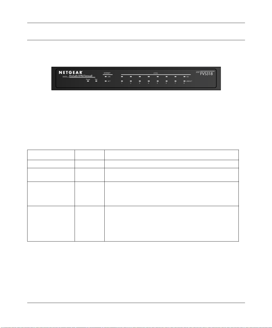
The front panel of the Model FVS318 Cable/DSL ProSafe VPN Firewall (Figure 2-1) contains
status LEDs.
Figure 2-1. FVS318 Front Panel
You can use some of the LEDs to verify connections. Table 2-1 lists and describes each LED on
the f ront panel of the firewall. These LEDs are green when lit, except for the TEST LED, which is
amber.
Table 2-1. LED Descriptions
Label Activity Description
POWER On Power is supplied to the firewall.
TEST On
Off
INTERNET
LINK On The Internet port has detected a link with an attached device.
ACT (Activity) Blinking Data is being transmitted or received by the Internet port.
LOCAL
100 (100 Mbps) On
Off
LINK/ACT
(Link/Activity)
On
Blinking
The system is initializing.
The system is ready and running.
The Local port is operating at 100 Mbps.
The Local port is operating at 10 Mbps.
The Local port has detected a link with an attached device.
Data is being transmitted or received by the Local port.
Setting Up the Hardware 2-3
Page 26
Reference Manual for the Model FVS318 Cable/DSL ProSafe VPN Firewall
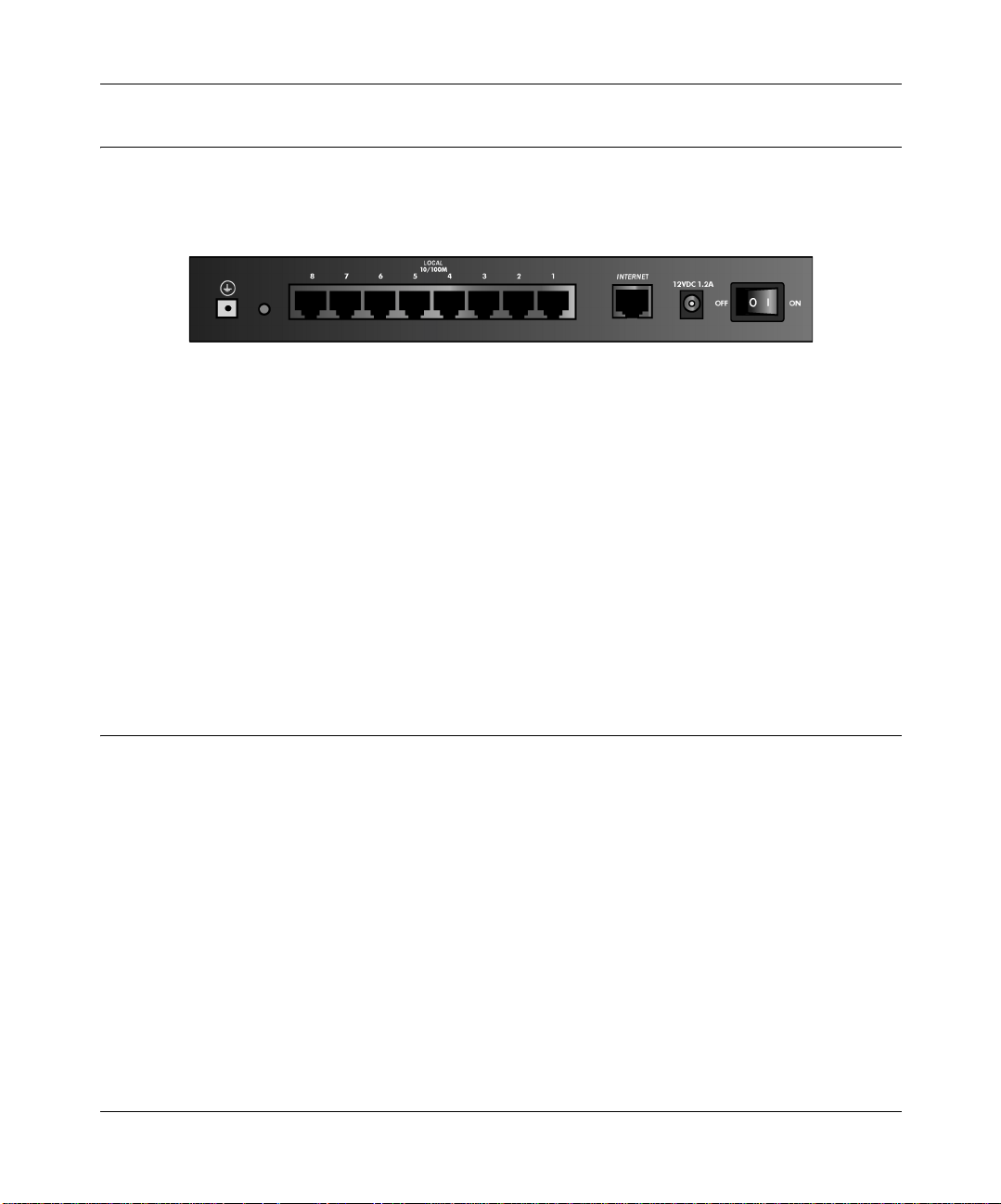
The Firewall’s Rear Panel
The rear panel of the FVS318 VPN Firewall (Figure 2-2) contains port connections.
Figure 2-2. FVS318 Rear Panel
The rear panel contains the following features:
• Power switch
• AC power adapter outlet
• Internet (WAN) Ethernet port for connecting the firewall to a cable or DSL modem
• Eight Local (LAN) Ethernet ports for connecting the firewall to the local PCs
• Factory Default Reset pushbutton
• Grounding terminal
Connecting the Firewall
Before using your firewall, you need to do the following:
• Connect your cable or DSL modem to the Internet port of the firewall (described next.
• Connect your local Ethernet network to the Local port(s) of the firewall (see page 2-5).
• Connect the power adapter (see page 2-6)
Note: The Resource CD included with your firewall contains an animated Connection Guide to
help you through this procedure.
2-4 Setting Up the Hardware
Page 27

Reference Manual for the Model FVS318 Cable/DSL ProSafe VPN Firewall
Connecting to Your Internet Access Device
Yourcable or DSL modem must provide a standard 10BASE-T Ethernet connection (not USB) for
connection to your PC or network. The FVS318 VPN Firewall does not include a cable for this
connection. Instead, use the Ethernet cable provided with your access device or any other standard
10BASE-T Ethernet cable. Follow these steps:
1. Locate the Ethernet cable currently going from your DSL or cable modem to the computer that
you use to access the Internet.
Note: You must use the existing cable to connect the modem to your firewall, not to connect
your PCs to your firewall. The Ethernet cable supplied by your ISP for connecting to your
cable or DSL modem may be an Ethernet crossover cable rather than a normal
straight-through cable.
2. Remove this cable from the computer and insert that end into the Internet port on the firewall.
3. Turn the cable or DSL modem off for ten seconds, then on again.
Connecting to your Local Ethernet Network
Your local area network (LAN) will attach to the firewall’s Local ports shown in Figure 2-2.The
Local ports are capable of operation at either 10 Mbps (10BASE-T) or 100 Mbps (100BASE-Tx),
depending on the Ethernet interface of the attached PC, hub, or switch. For any connection which
will operate at 100 Mbps, you must use a Category 5 (CAT5) rated Ethernet cable, such as the
cable included with the firewall.
The FVS318 VPN Firewall incorporates an eight-port switch for connection to your local network.
Connect up to eight PCs directly t o any of the eight Local ports of the firewall using standard
Ethernet cables such as the one included with your firewall.
If your local network consists of more than eight hosts, you will need to connect your firewall to
another hub or switch. In this case, c onnect any LOCAL port of your firewall to any port of an
Ethernet hub or switch. The firewall’s LOCAL port will automatically configure itself for the
uplink connection.
Note: The FVS318 V PN Firewall incorporates Auto Uplink
TM
technology. Each LOCAL Ethernet
port will automatically sense whether the Ethernet cable plugged into the port should have a
'normal' connection (e.g. connecting to a PC) or an 'uplink' connection (e.g. connecting to a switch
or hub). That port will then configure itself to the correct configuration. This feature also
eliminates the need to w orry about crossover cables, as Auto Uplink will accommodate either type
of cable to make the right connection.
Setting Up the Hardware 2-5
Page 28

Reference Manual for the Model FVS318 Cable/DSL ProSafe VPN Firewall
Connecting the Power Adapter
To connect the firewall to the power adapter:
1. Plug the connector of the power adapter into the power adapter outlet on the rear panel of the
firewall.
2. Plug the other end of the adapter into a standard wall outlet.
3. Turn the Power switch to the ON position.
4. Verifythat the Power LED on the firewall is lit.
Verifying Connections
After applying power to the firewall, complete the following steps to verify the connections to it:
1. When power is first applied, verify that the POWER LED is on.
2. Verifythat the TEST LED turns on within a few seconds.
3. After approximately 10 seconds, verify that:
a. The TEST LED has turned off.
b. The LOCAL LINK/ACT LEDs are lit for any local ports that are connected.
c. The INTERNET LINK/ACT LED is lit.
If a LINK/ACT LED is lit, a link has been established to the connected device.
4. If any LOCAL port is connected to a 100 Mbps device, verify that the 100 LED for that port is
lit.
The firewall is now properly attached to the network. Next, you need to prepare your network to
access the Internet through the firewall. See the following chapter.
2-6 Setting Up the Hardware
Page 29
Chapter 3
Preparing Your Network
This chapter describes how to prepare your PC network to connect to the Internet through the
Model FVS318 Cable/DSL ProSafe VPN Firewall and how to order broadband Internet service
from an Internet service provider (ISP). .
Note: If an ISP technician configured your PC during the installation of a broadband
modem, or if you configured it using instructions provided by your ISP, you may need to
copy the current configuration information for use in the configuration of your firewall.
Write down this information before reconfiguring your PCs. Refer to “Obtaining ISP
Configuration Information (Windows)”onpage 3-10 or “Obtaining ISP Configuration
Information (Macintosh)”onpage 3-11 for further information.
Preparing Your Personal Computers for IP Networking
Personal Computers access the Internet using a protocol called TCP/IP (Transmission Control
Protocol/Internet Protocol). Each PC on your network must have TCP/IP installed and selected as
its networking protocol. If a Network Interface Card (NIC) is already installed in your PC, then
TCP/IP is probably already installed as well.
Note: In this chapter, we use the term “PC” to refer to personal computers in general, and not
necessarily Windows computers.
Most PC operating systems include the software components you need for networking with TCP/
IP:
®
• Windows
• Windows 3.1 does not include a TCP/IP component. You need to purchase a third-party TCP/
IP application package such as NetManage Chameleon.
Preparing Your Network 3-1
95 or later includes the software components for establishing a TCP/IP network.
Page 30

Reference Manual for the Model FVS318 Cable/DSL ProSafe VPN Firewall
• Macintosh Operating System 7 or later includes the software components for establishing a
TCP/IP network.
• All versions of UNIX or Linux include TCP/IP components. Follow the instructions provided
with your operating system or networking software to install TCP/IP on your computer..
In your IP network, each PC and the firewall must be assigned a unique IP addresses. Each PC
must also have certain other IP configuration information such as a subnet mask (netmask), a
domain name server (DNS) address, and a default gateway address. In most cases, you should
install TCP/IP so that the PC obtains its specific network configuration information automatically
from a DHCP server during bootup. For a detailed explanation of the meaning and purpose of
these configuration items, refer to “Appendix B, “Networks, Routing, and Firewall Basics.”
The FVS318 VPN Firewall is shipped preconfigured as a DHCP server. The firewall assigns the
following TCP/IP configuration information automatically when the PCs are rebooted:
• PC or workstation IP addresses—192.168.0.2 through 192.168.0.254
• Subnet mask—255.255.255.0
• Gateway address (the firewall)—192.168.0.1
These addresses are part of the IETF-designated private address range for use in private networks.
Configuring Windows 95, 98, and ME for IP Networking
As part of the PC preparation process, you need to manually install and configure TCP/IP on each
networked PC. Before starting, locate your Windows CD; you may need to insert it during the
TCP/IP installation process.
Install or Verify Windows Networking Components
To install or verify the necessary components for IP networking:
1. On the Windows taskbar, click the Start button, point to Settings, and then click Control Panel.
2. Double-click the Network icon.
The Network window opens, which displays a list of installed components:
3-2 Preparing Your Network
Page 31

Reference Manual for the Model FVS318 Cable/DSL ProSafe VPN Firewall
You must have an Ethernet adapter, the TCP/IP protocol, and Client for Microsoft Networks.
Note: It is not necessary to remove any other network components shown in the
Network window in order to install the adapter, TCP/IP, or Client for Microsoft
Networks.
Ifyouneedtheadapter:
a. Click the Add button.
b. Select Adapter,and then click Add.
c. Select the manufacturer and m odel of your Ethernet adapter, and then click OK.
If you need TCP/IP:
a. Click the Add button.
b. Select Protocol, and then click Add.
c. Select Microsoft.
Preparing Your Network 3-3
Page 32

Reference Manual for the Model FVS318 Cable/DSL ProSafe VPN Firewall
d. Select TCP/IP, and then click OK.
If you need Client for Microsoft Networks:
a. Click the Add button.
b. Select Client, and then click Add.
c. Select Microsoft.
d. Select C lient for Microsoft Networks, and then click OK.
3. Restart your PC for the changes to take effect.
Assign TCP/IP configuration by DHCP
After the TCP/IP protocol components are installed, each PC must be assigned specific
information about itself and resources that are available on its network. The simplest way to
configure this information is to allow the PC to obtain the information from the internal DHCP
server of the FVS318 VPN Firewall. To use DHCP with the recommended default addresses,
follow these steps:
1. Connect all PCs to the firewall, then restart the firewall and allow it to boot.
2. On each attached PC, open the Network control panel (refer to the previous section) and select
the Configuration tab.
3. From the components list, select TCP/IP->(your Ethernet adapter) and click Properties.
4. In the IP Address tab, select “Obtain an IP address automatically”.
5. Select the Gateway tab.
6. If any gateways are shown, remove them.
7. Click OK.
8. Restart the PC.
Repeat steps 2 through 8 for each PC on your network.
Selecting Internet Access Method
1. On the Windows taskbar, click the Start button, point to Settings, and then click Control Panel.
2. Double-click the Internet Options icon.
3-4 Preparing Your Network
Page 33

Reference Manual for the Model FVS318 Cable/DSL ProSafe VPN Firewall
3. Select “I want to set up my Internet connection manually” or “I want to connect through a
Local Area Network” and click Next.
4. Select “I want to connect through a Local Area Network” and click Next.
5. Uncheck all boxes in the LAN Internet Configuration screen and click Next.
6. ProceedtotheendoftheWizard.
Verifying TCP/IP Properties
After your PC is configured and has rebooted, you can check the TCP/IP configuration using the
utility winipcfg.exe:
1. On the Windows taskbar, click the Start button, and then click Run.
2. Type winipcfg, and then click OK.
The IP Configuration window opens, which lists (among other things), your IP address, subnet
mask, and default gateway.
3. From the drop-down box, select your Ethernet adapter.
The window is updated to show your settings, which should match the values below if you are
using the default TCP/IP settings that NETGEAR recommends:
• The IP address is between 192.168.0.2 and 192.168.0.254
• The subnet mask is 255.255.255.0
• The default gateway is 192.168.0.1
Configuring Windows NT or 2000 for IP Networking
As part of the PC preparation process, you need to manually install and configure TCP/IP on each
networked PC. Before starting, locate your Windows CD; you may need to insert it during the
TCP/IP installation process.
Install or Verify Windows Networking Components
To install or verify the necessary components for IP networking:
1. On the Windows taskbar, click the Start button, point to Settings, and then click Control Panel.
2. Double-click the Network and Dialup Connections icon.
Preparing Your Network 3-5
Page 34

Reference Manual for the Model FVS318 Cable/DSL ProSafe VPN Firewall
3. If an Ethernet adapter is present in your PC, you should see an entry for Local Area
Connection. Double-click that entry.
4. Select Properties.
5. Verifythat ‘Client for Microsoft Networks’ and ‘Internet Protocol (TCP/IP)’ are present. If
not, select Install and add them.
6. Select ‘Internet Protocol (TCP/IP)’, click Properties, and verify that “Obtain an IP address
automatically is selected.
7. Click OK and close all Network and Dialup Connections windows.
8. Make sure your PC is connected to the firewall, then reboot your PC.
Verifying TCP/IP Properties
To check your PC’s TCP/IP configuration:
1. On the Windows taskbar, click the Start button, and then click Run.
The Run window opens.
2. Type cmd and then click OK.
A command window opens
3. Type ipconfig /all
YourIP Configuration information will be listed, and should match the values below if you are
using the default TCP/IP settings that NETGEAR recommends:
• The IP address is between 192.168.0.2 and 192.168.0.254
• The subnet mask is 255.255.255.0
• The default gateway is 192.168.0.1
4. Type exit
Configuring the Macintosh for IP Networking
Beginning with Macintosh Operating System 7, TCP/IP is already installed on the Macintosh. On
each networked Macintosh, you will need to configure TCP/IP to use DHCP.
3-6 Preparing Your Network
Page 35

Reference Manual for the Model FVS318 Cable/DSL ProSafe VPN Firewall
MacOS 8.6 or 9.x
1. From the Apple menu, select Control Panels, then TCP/IP.
The TCP/IP Control Panel opens:
2. From the “Connect via” box, select your Macintosh’s Ethernet interface.
3. From the “Configure” box, select Using DHCP Server.
You can leave the DHCP Client ID box empty.
4. Close the TCP/IP Control Panel.
5. Repeat this for each Macintosh on your network.
MacOS X
1. From the Apple menu, choose System Preferences, then Network.
2. If not already selected, select Built-in Ethernet in the Configure list.
3. If not already selected, Selct Using DHCP in the TCP/IP tab.
4. Click Save.
Preparing Your Network 3-7
Page 36

Reference Manual for the Model FVS318 Cable/DSL ProSafe VPN Firewall
Verifying TCP/IP Properties (Macintosh)
After your Macintosh is configured and has rebooted, you can check the TCP/IP configuration by
returning to the TCP/IP Control Panel. From the Apple menu, select Control Panels, then TCP/IP.
The panel is updated to show your settings, which should m atch the values below if you are using
the default TCP/IP settings that NETGEAR recommends:
• The IP Address is between 192.168.0.2 a nd 192.168.0.254
• The Subnet mask is 255.255.255.0
• The Router address is 192.168.0.1
If you do not see these values, you may need to restart your Macintosh or you may need to switch
the “Configure” setting to a different option, then back again to “Using DHCP Server”.
Your Internet Account
For access to the Internet, you need to contract with an Internet service provider (ISP) for a
single-user Internet access account using an external broadband access device such as a cable
modem or DSL m odem. This modem must be a separate physical box (not a card) and must
provide an Ethernet port intended for connection to a Network Interface Card (NIC) in a PC. Your
firewall does not support a USB-connected broadband modem.
3-8 Preparing Your Network
Page 37

Reference Manual for the Model FVS318 Cable/DSL ProSafe VPN Firewall
For a single-user Internet account, your ISP supplies TCP/IP configuration information for one
PC. With a typical account, much of the configuration information is dynamically assigned when
your PC is first booted up while connected to the ISP, and you will not need to know that dynamic
information.
In order to share the Internet connection among several computers, your firewall takes the place of
the single PC, and you need to configure it with the TCP/IP information that the single PC would
normally use. When the firewall’sInternet port is connected to the broadband modem, the firewall
appears to be a single PC to the ISP. The firewall then allows the PCs on the local network to
masquerade as the single PC to access the Internet through the broadband modem. The method
used by the firewall to accomplish this is called Network Address Translation (NAT) or IP
masquerading.
Login Protocols
Some ISPs require a special login protocol, in which you must enter a login name and password in
order to access the Internet. If you normally log in to your Internet account by running a program
such as WinPOET or EnterNet, then your account uses PPP over Ethernet (PPPoE).
When you configure your firewall, you will need to enter your login name and password in the
firewall’s configuration menus. After your network and firewall are configured, the firewall will
perform the login task when needed, and you will no longer need to run the login program from
your PC. It is not necessary to uninstall the login program.
Account Information
Unless these items are dynamically assigned by the ISP, your ISP should give you the following
basic information for your account:
• An IP address and subnet m ask
• A gateway IP address, which is the address of the ISP’s router
• One or more domain name server (DNS) IP addresses
• Host name and domain suffix
For example, your account’s full server names may look like this:
mail.xxx.yyy.com
In this example, the domain suffix is xxx.yyy.com.
Preparing Your Network 3-9
Page 38

Reference Manual for the Model FVS318 Cable/DSL ProSafe VPN Firewall
If any of these items are dynamically supplied by the ISP, your firewall automatically acquires
them. If an ISP technician configured your PC during the installation of the broadband modem, or
if you configured it using instructions provided by your ISP, you need to copy configuration
information from your PC’s Network TCP/IP Properties window (or Macintosh TCP/IP Control
Panel) before reconfiguring your PC for use with the firewall. These procedures are described
next.
Obtaining ISP Configuration Information (Windows)
As mentioned above, you may need to collect configuration information from your PC so that you
can use this information when you configure the FVS318 VPN Firewall. Following this procedure
is only necessary when your ISP does not dynamically supply the account information.
To get the information you need to configure the firewall for Internet access:
1. On the Windows taskbar, click the Start button, point to Settings, and then click Control Panel.
2. Double-click the Network icon.
The Network window opens, which displays a list of installed components.
3. Select TCP/IP, and then click Properties.
The TCP/IP Properties dialog box opens.
4. Select the IP Address tab.
If an IP address and subnet mask are shown, w rite down the information. If an address is
present, your account uses a fixed (static) IP address. If no address is present, your account
uses a dynamically-assigned IP address. Click “Obtain an IP address automatically”.
5. Select the Gateway tab.
If an IP address appears under Installed Gateways, write down the address. This is the ISP’s
gateway address. Select the address and then click Remove to remove the gateway address.
6. Select the DNS Configuration tab.
If any DNS server addresses are shown, write down the addresses. If any information appears
in the Host or Domain information box, write it down. Click Disable DNS.
7. Click OK to save your changes and close the TCP/IP Properties dialog box.
You are returned to the Network window.
8. Click OK.
9. Reboot your PC at the prompt. You may also be prompted to insert your Windows CD.
3-10 Preparing Your Network
Page 39

Reference Manual for the Model FVS318 Cable/DSL ProSafe VPN Firewall
Obtaining ISP Configuration Information (Macintosh)
As mentioned above, you may need to collect configuration information from your Macintosh so
that you can use this information when you configure the FVS318 VPN Firewall. Following this
procedure is only necessary when your ISP does not dynamically supply the account information.
To get the information you need to configure the firewall for Internet access:
1. From the Apple menu, select Control Panels, then TCP/IP.
The TCP/IP Control Panel opens, which displays a list of configuration settings. If the
“Configure” setting is “Using DHCP Server”, your account uses a dynamically-assigned IP
address. In this case, close the Control Panel and skip the rest of this section.
2. If an IP address and subnet mask are shown, write down the information.
3. If an IP address appears under Router address, write down the address. This is the ISP’s
gateway address.
4. If any Name Server addresses are shown, write down the addresses. These are your ISP’s DNS
addresses.
5. If any information appears in the Search domains information box, write it down.
6. Change the “Configure” setting to “Using DHCP Server”.
7. Close the TCP/IP Control Panel.
Restarting the Network
Once you’ve set up your computers to work with the firewall, you must reset the network for the
devices to be able to communicate correctly.
1. Turn off the DSL or cable modem, wait 15 seconds, and then turn it on again
2. Turn off the firewall, and then turn it on again and wait until the Test light turns off.
3. Restart any computer that is connected to the firewall.
Note: If the modem doesn’t have an on/off switch, either pull the modem’s power adapter out of
the wall socket or power down the power strip.
Preparing Your Network 3-11
Page 40

Reference Manual for the Model FVS318 Cable/DSL ProSafe VPN Firewall
Ready for Configuration
After configuring all of your PCs for TCP/IP networking and connecting them to the local network
of your FVS318 VPN Firewall, you are ready to access and configure the firewall. Proceed to the
next chapter.
3-12 Preparing Your Network
Page 41

Chapter 4
Basic Configuration
This chapter describes how to perform the basic configuration of your Model FVS318 Cable/DSL
ProSafe VPN Firewall using the Setup Wizard, which w alks you through the configuration process
for your Internet connection.
Accessing the Web Configuration Manager
In order to use the browser-based Web Configuration Manager, your PC must have a web browser
program installed such as Microsoft Internet Explorer or Netscape Navigator. Because the
Configuration Manager uses Java, your Web browser must be Java-enabled and support HTTP
uploads. NETGEAR recommends using Microsoft Internet Explorer or Netscape Navigator 4.0 or
above. Free browser programs are readily available for Windows, Macintosh, or UNIX/Linux.
To configure for Internet access using your browser:
1. Connect your PC and firewall as described in the previous chapter.
Make sure your PC has been rebooted since connecting with the firewall.
2. Launch your web browser.
Note: If you normally use a login program (such as Enternet or WinPOET) to access the
Internet, do not launch that program.
3. Click your browser’s Stop button.
4. In the Address (or Location) box of your browser, type http://192.168.0.1 and press ENTER.
Basic Configuration 4-1
Page 42

Reference Manual for the Model FVS318 Cable/DSL ProSafe VPN Firewall
A login window opens as shown in Figure 4-1 below:.
Figure 4-1. Login window
This screen may have a different appearance in other browsers.
5. Type admin in the User Name box, password in the Password box, and then click OK.
(If your firewall password was previously changed, enter the current password.)
If your firewall has not yet been configured, the Setup Wizard should launch automatically.
Otherwise, the main menu of the Web Configuration Manager will appear as shown in Figure 4-2
below:
4-2 Basic Configuration
Page 43

Reference Manual for the Model FVS318 Cable/DSL ProSafe VPN Firewall
Figure 4-2. Browser-based configuration main menu
You can manually configure your firewall using this menu as described in “Manual
Configuration“ on page 4-8, or you can allow the Setup Wizard to determine your configuration as
described in the following chapter.
Basic Configuration 4-3
Page 44

Reference Manual for the Model FVS318 Cable/DSL ProSafe VPN Firewall
Configuration using the Setup Wizard
The Web Configuration Manager contains a Setup Wizard that can automatically determine your
network connection type. If the Setup Wizard does not launch automatically, click on the Setup
Wizard heading in the upper left of the opening screen, shown in Figure 4-2.
When the Wizard launches, allow the firewall to automatically determine your connection type by
selecting Yes in the menu below and clicking Next:
The Setup Wizard will now check for a connection on the Internet port. If the Setup Wizard
determines that there is no connection to the Internet port, you will be prompted to check the
physical connection between your firewall and cable or DSL modem. When the connection is
properly made, the firewall’s Internet LED should be on.
Next, the Setup Wizard will attempt to determine which of the following c onnection types
your Internet service account uses:
• Dynamic IP assignment
• Fixed IP address assignment
• A login protocol such as PPPoE
The Setup Wizard will report which connection type it has discovered, and it will then use the
appropriate configuration menu for that connection type.
4-4 Basic Configuration
Page 45

Reference Manual for the Model FVS318 Cable/DSL ProSafe VPN Firewall
Configuring for Dynamic IP Account
If the Setup Wizard determines that your Internet service account uses Dynamic IP assignment,
you will be directed to the m enu shown in Figure 4-3 below:
Figure 4-3. Setup Wizard menu for Dynamic IP address
1. Enter your Account Name (may also be called Host Name) and Domain Name. These
parametersmay be necessary to access your ISP’s services such as mail or news servers. If you
leave the Domain Name field blank, the firewall will attempt to learn the domain
automatically from the ISP. If this is not successful, you may need to enter it manually.
2. Domain Name Server (DNS) Address: If you know that your ISP does not automatically
transmit DNS addresses to the firewall during login, select “Use these DNS servers” and enter
the IP address of your ISP’s Primary DNS Server. If a Secondary DNS Server address is
available, enter it also.
A DNS server is a host on the Internet that translates Internet names (such as www
addresses)to numeric IP addresses. Typicallyyour ISP transfers the IP addresses of one or
two DNS servers to your firewall during login. If the ISP does not transfer an address, you
must obtain it from the ISP and enter it manually here. If you enter an address here, you
should reboot your PCs after configuring the firewall.
Basic Configuration 4-5
Page 46

Reference Manual for the Model FVS318 Cable/DSL ProSafe VPN Firewall
3. Router’s MAC Address: This section determines the Ethernet MAC address that will be used
by the firewall on the Internet port. If your ISP allows access by only one specific PC’s
Ethernet MAC address, select "Use this MAC address". The firewall will then capture and use
the MAC address of the PC that you are now using. You must be using the one PC that is
allowedbytheISP.
Some ISPs will register the Ethernet MAC address of the network interface card in your
PC when your account is first opened. They will then only accept traffic from the MAC
address of that PC. This feature allows your firewall to masquerade as that PC by using its
MAC address.
4. ClickonApply,thenproceedto“Completing the Configuration“ on page 4-9.
Configuring for Fixed IP Account
If the Setup Wizard determines that your Internet service account uses Fixed IP assignment, you
will be directed to the menu shown in Figure 4-4 below:
Figure 4-4. Setup Wizard menu for Fixed IP address
Enter your assigned IP Address, Subnet Mask, and the IP Address of your ISP’s gateway
1.
router. This information should have been provided to you by your ISP.
2. Domain Name Server (DNS) Address: If you know that your ISP does not automatically
transmit DNS addresses to the firewall during login, select “Use these DNS servers” and enter
the IP address of your ISP’s Primary DNS Server. If a Secondary DNS Server address is
available, enter it also.
4-6 Basic Configuration
Page 47

Reference Manual for the Model FVS318 Cable/DSL ProSafe VPN Firewall
A DNS server is a host on the Internet that translates Internet names (such as www
addresses)to numeric IP addresses. Typicallyyour ISP transfers the IP addresses of one or
two DNS servers to your firewall during login. If the ISP does not transfer an address, you
must obtain it from the ISP and enter it manually here. If you enter an address here, you
should reboot your PCs after configuring the firewall.
3. ClickonApply,thenproceedto“Completing the Configuration“ on page 4-9.
Configuring for an Account with Login
If the Setup Wizard determines that your Internet service account uses a login protocol such as
PPP over Ethernet (PPPoE), you w ill be directed to a menu like the PPPoE menu shown in
Figure 4-5 below:
Figure 4-5. Setup Wizard menu for PPPoE login accounts
Enter your Account Name (may also be called Host Name) and Domain Name. These
1.
parametersmay be necessary to access your ISP’s services such as mail or news servers. If you
leave the Domain Name field blank, the firewall will attempt to learn the domain
automatically from the ISP. If this is not successful, you may need to enter it manually.
2. Enter the PPPoE login user name and password provided by your ISP. These fields are case
sensitive. If you wish to change the login timeout, enter a new value in minutes.
Basic Configuration 4-7
Page 48

Reference Manual for the Model FVS318 Cable/DSL ProSafe VPN Firewall
Note: You will no longer need to launch the ISP’slogin program on your PC in order to access
the Internet. When you start an Internet application, your firewall will automatically log you
in.
3. Domain Name Server (DNS) Address: If you know that your ISP does not automatically
transmit DNS addresses to the firewall during login, select “Use these DNS servers” and enter
the IP address of your ISP’s Primary DNS Server. If a Secondary DNS Server address is
available, enter it also.
A DNS server is a host on the Internet that translates Internet names (such as www
addresses)to numeric IP addresses. Typicallyyour ISP transfers the IP addresses of one or
two DNS servers to your firewall during login. If the ISP does not transfer an address, you
must obtain it from the ISP and enter it manually here. If you enter an address here, you
should reboot your PCs after configuring the firewall.
4. ClickonApply,thenproceedto“Completing the Configuration“ on page 4-9.
Manual Configuration
You can manually configure the firewall in the Basic Settings menu shown in Figure 4-2 using
these steps:
1. Select w hether your Internet connection requires a login.
Select ‘Yes’ if you normally must launch a login program such as Enternet or WinPOET in
order to access the Internet.
2. Enter your Account Name (may also be called Host Name) and Domain Name. These
parameters may be necessary to access your ISP’s services such as mail or news servers.
3. (If displayed) Enter the PPPoE login user name and password provided by your ISP. These
fields are case sensitive. If you wish to change the login timeout, enter a new value in minutes.
Note: You will no longer need to launch the ISP’slogin program on your PC in order to access
the Internet. When you start an Internet application, your firewall will automatically log you
in.
4. Internet IP Address: If your ISP has assigned you a permanent, fixed (static) IP address for
your PC, select “Use static IP address”. Enter the IP address that your ISP assigned. Also enter
the netmask and the Gateway IP address. The Gateway is the ISP’s router to which your
firewall w ill connect.
4-8 Basic Configuration
Page 49

Reference Manual for the Model FVS318 Cable/DSL ProSafe VPN Firewall
5. Domain Name Server (DNS) Address: If you know that your ISP does not automatically
transmit DNS addresses to the firewall during login, select “Use these DNS servers” and enter
the IP address of your ISP’s Primary DNS Server. If a Secondary DNS Server address is
available, enter it also.
A DNS server is a host on the Internet that translates Internet names (such as www
addresses)to numeric IP addresses. Typicallyyour ISP transfers the IP addresses of one or
two DNS servers to your firewall during login. If the ISP does not transfer an address, you
must obtain it from the ISP and enter it manually here. If you enter an address here, you
should reboot your PCs after configuring the firewall.
6. Router’s MAC Address: This section determines the Ethernet MAC address that will be used
by the firewall on the Internet port. Some ISPs will register the Ethernet MAC address of the
network interface card in your PC when your account is first opened. They will then only
accept traffic from the MAC address of that PC. This feature allows your firewall to
masquerade as that PC by “cloning” its MAC address.
To change the MAC address, select "Use this Computer’s M AC address". The firewall will
then capture and use the MAC address of the PC that you are now using. You must be using
the one PC that is allowed by the ISP.
7. Click Apply, then proceed to Completing the Configuration.
Completing the Configuration
Click on the Test button to test your Internet connection. If the NETGEAR website does not
appear within one minute, refer to Chapter 9, “Troubleshooting”.
Your firewall is now configured to provide Internet access for your network. When your firewall
and PCs are configured correctly, your firewall automatically accesses the Internet when one of
your LAN devices requires access. It is not necessary to run a dialer or login application such as
Dial-Up Networking or Enternet to connect, log in, or disconnect. These functions are performed
by the firewall as needed.
To access the Internet from any PC connected to your firewall, launch a browser such as Microsoft
Internet Explorer or Netscape Navigator. You should see the firewall’s Internet LED blink,
indicating communication to the ISP. The browser should begin to display a Web page.
The following chapters describe how to configure the Advanced features of your firewall, and how
to troubleshoot problems that may occur.
Basic Configuration 4-9
Page 50

Reference Manual for the Model FVS318 Cable/DSL ProSafe VPN Firewall
4-10 Basic Configuration
Page 51

Chapter 5
Configuring Security Features
This chapter describes how to use the security features of your Model FVS318 Cable/DSL ProSafe
VPN Firewall. The firewall provides you with Web content filtering by keyword, and with security
incident logging. You can configure the firewall to e-mail its log to you at specified intervals. You
can also configure the firewall to send immediate alert messages to your e-mail address or e-mail
pager whenever a significant security event occurs.
To configure these features of your firewall, click on the subheadings under the Security heading
in the Main Menu of the browser interface.
Configuring Security Features 5-1
Page 52

Reference Manual for the Model FVS318 Cable/DSL ProSafe VPN Firewall
Security Log
The firewall will log security-related events such as denied incoming service requests, hacker
probes, and administrator logins. If you enabled content filtering in the Block Sites menu, the Logs
page shows you when someone on your network tried to access a blocked site. If you enabled
e-mail notification, you'll receive these logs in an e-mail message. If you don't have e-mail
notification enabled, you can view the logs here. An example is shown below:
Log entries are described in Table 5-1
Table 5-1. Log entry descriptions
Field Description
Date and Time The date and time the log entry was recorded.
Description or
The type of event and what action was taken if any.
Action
Source IP The IP address of the initiating device for this log entry.
Source port and
interface
The service port number of the initiating device, and whether it
originated from the LAN or WAN
Destination The name or IP address of the destination device or website.
Destination port
and interface
5-2 Configuring Security Features
The service port number of the destination device, and whether
it’s on the LAN or WAN.
Page 53

Reference Manual for the Model FVS318 Cable/DSL ProSafe VPN Firewall
Log action buttons are described in Table 5-2
Table 5-2. Log action buttons
Field Description
Refresh Click this button to refresh the log screen.
Clear Log Click this button to clear the log entries.
Send Log
Click this button to email the log immediately.
Block Sites
The FVS318 VPN Firewall allows you to restrict access based on Web addresses and Web address
keywords. Up to 255 entries are supported in the Keyword list. The Keyword Blocking menu is
shown below:
To enable keyword blocking, check “Turn keyword blocking on”, then click Apply. Be sure that a
time period for blocking is specified on the Schedule m enu.
To add a keyword or domain, type it in the Keyword box, click Add Keyword, then click Apply.
To delete a keyword or domain, select it from the list, click Delete Keyword, then click Apply.
Configuring Security Features 5-3
Page 54

Reference Manual for the Model FVS318 Cable/DSL ProSafe VPN Firewall
Keyword application examples:
• If the keyword "XXX" is specified, the URL <http://www.badstuff.com/xxx.html> is blocked.
• If the keyword “.com” is specified, only websites with other domain suffixes (such as .edu or
.gov) can be viewed.
• If you wish to block all Internet browsing access during a scheduled period, enter the keyword
“.” and set the schedule in the Schedule menu.
To specify a Trusted User, enter that PC’s IP address in the Trusted User box and click Apply.
You may specify one Trusted User, w hich is a PC that will be exempt from blocking and
logging. Since the Trusted User will be identified by an IP address, you should configure that
PC with a fixed IP address.
5-4 Configuring Security Features
Page 55

Reference Manual for the Model FVS318 Cable/DSL ProSafe VPN Firewall
Schedule
If you enabled content filtering in the Block Sites menu, you can set up a schedule for when
blocking occurs or when access isn't restricted. The firewall allows you to specify when blocking
will be enforced by configuring the Schedule tab shown below:
To block keywords or Internet domains based on a schedule:
1. Select Every Day or select one or more days.
2. If you want to limit access completely for the selected days, select All Day.
Otherwise, If you want to limit access during certain times for the selected days, type a Start
Blocking time and an End Blocking time.
Note: Note: Enter the values as 24-hour time. For example, 10:30 am would be 10 hours and
30 minutes and 10:30 pm would be 22 hours and 30 minutes.
3. Click Apply
Configuring Security Features 5-5
Page 56

Reference Manual for the Model FVS318 Cable/DSL ProSafe VPN Firewall
Time Zone
The FVS318 VPN Firewall uses the Network Time Protocol (NTP) to obtain the current time and
date from one of several Network Time Servers on the Internet. In order to localize the time for
your log entries, you must select your Time Zone from t he list.
If your region uses Daylight Savings Time, you must manually check Adjust for Daylight Savings
Time at the beginning of the Daylight Savings Time, and uncheck it at the end. Enabling Daylight
Savings Time will cause one hour to be added to the standard time.
The firewall has a list of publicly available NTP servers. If you would prefer to use a particular
NTP server as the primary server, enter its IP address under Use this NTP Server.
5-6 Configuring Security Features
Page 57

Reference Manual for the Model FVS318 Cable/DSL ProSafe VPN Firewall
In order to receive logs and alerts by e-mail, you must provide your e-mail information in the
E-Mail subheading:
• Turn e-mail notification on
Check this box if you wish to receive e-mail logs and alerts from the firewall.
• Your outgoing mail server
Enter the name or IP address of your ISP’s outgoing (SMTP) mail server (such as
mail.myISP.com). You may be able to find this information in the configuration menu of your
e-mail program. If you leave this box blank, log and alert messages will not be sent via e-mail.
• Sendtothise-mailaddress
Enter the e-mail address to w hich logs and alerts are sent. This e-mail address will also be used
as the From address. If you leave this box blank, log and alert messages will not be sent via
e-mail.
You can specify that logs are automatically sent to the specified e-mail address with these options:
• Send alert immediately
Check this box if you would like immediate notification of a significant security event, such as
a known attack, port scan, or attempted access to a blocked site.
Configuring Security Features 5-7
Page 58

Reference Manual for the Model FVS318 Cable/DSL ProSafe VPN Firewall
• Send logs according to this schedule
Specifies how often to send the logs: H ourly, Daily, Weekly, or When Full.
– Day for sending log
Specifies which day of the week to send the log. Relevant when the log is sent weekly or
daily.
– Time for sending log
Specifies the time of day to send the log. Relevant when the log is sent daily or weekly.
If the Weekly, Daily or Hourly option is selected and the log fills up before the specified
period, the log is automatically e-mailed to the specified e-mail address. After the log is sent,
the log is cleared from the firewall’s memory. If the firewall cannot e-mail the log file, the log
buffer may fill up. In this case, the firewall overwrites the log and discards its contents.
The FVS318 VPN Firewall uses the Network Time Protocol (NTP) to obtain the current time and
date from one of several Network Time Servers on the Internet. In order to localize the time for
your log entries, you must specify your Time Zone:
•TimeZone
Select your local time zone. This setting will be used for the blocking schedule and for
time-stamping log entries.
• Daylight Savings Time
Check this box if your time zone is currently under daylight savings time.
5-8 Configuring Security Features
Page 59

Chapter 6
Virtual Private Networking
This chapter describes how to use the the virtual private networking (VPN) features of the FVS318
VPN Firewall. A VPN provides secure, encrypted communication between your local network and
a remote network or computer.
Note: The FVS318 VPN Firewall uses industry standard VPN protocols. However, due
to variations in how manufacturers interpret these standards, many VPN products are
not interoperable. NETGEAR provides support for connections between two FVS318
VPN Firewalls, and between an FVS318 VPN Firewall and the SafeNet Secure VPN
Client for Windows. Although the FVS318 can interoperate with many other VPN
products,it is not possible for NETGEAR t o provide specific technical support for every
other interconnection.
Virtual Private Networking 6-1
Page 60

Reference Manual for the Model FVS318 Cable/DSL ProSafe VPN Firewall
WhatisaVPN
A VPN can be thought of as a secure tunnel passing through the Internet, connecting two devices
such as a PC or router, which form the two tunnel endpoints. At one endpoint, data is encapsulated
and encrypted, then transmitted through the Internet. At the far endpoint, the data is received,
unencapsulated and decrypted. Although the data may pass through several Internet routers
between the endpoints, the encapsulation and encryption forms a virtual “tunnel” for the data.
DATA PACKET
ENCRYPTION AND ENCAPSULATION
INTERNET
TRANSMISSION
VIA INTERNET
UNENCAPSULATION AND DECRYPTION
DATA PACKET
The tunnel endpoint device, which encodes or decodes t he data, can either be a PC running VPN
client software or a VPN-enabled router or server. Several software standards exist for VPN data
encapsulation and encryption, such as PPTP and IPSec. Your FVS318 VPN Firewall uses IPSec.
To set up a VPN connection, you must configure each endpoint with specific identification and
connection information describing the other endpoint. This set of configuration information
defines a security association (SA) between the two points. The FVS318 is capable of eight
Security Associations.
Two common applications of VPN are
• secure access from a remote PC, such as a telecommuter connecting to an office network
• secure access between two networks, such as a branch office and a main office
These applications are described below.
6-2 Virtual Private Networking
Page 61

Reference Manual for the Model FVS318 Cable/DSL ProSafe VPN Firewall
C
N
C
N
Accessing Network Resources from a VPN Client PC
VPN client remote access allows a remote PC to connect to your network from any location on the
Internet. In this case, the remote PC is one tunnel endpoint, running VPN client software. The
NETGEAR VPN-enabled router on your network is the other tunnel endpoint, as shown below.
VPN
LIENT
ATLANTA BAY
SANTACLARA
INTERNET
ROUTER
LA
In some cases, the client PC may connect to the Internet through a local non-VPN-enabled router,
as shown below:
LIENT
ATLANTA BAY
SANTACLARA
SIMPLE
ROUTER
INTERNET
VPN
ROUTER
LA
If the non-VPN router is performing NAT, it must support “VPN-passthrough” of IPSec-encoded
data.
For a PC to act as a tunnel endpoint to your FVS318 VPN Firewall, the PC must run a VPN client
program based on the IPSec protocol. NETGEAR recommends that you use the SafeNet
SoftRemote (or Soft-PK) VPN client program, which is available from SafeNet
(www.safenet-inc.com). Installation and configuration instructions for the SafeNet client program
are provided on page 6-13.
Virtual Private Networking 6-3
Page 62

Reference Manual for the Model FVS318 Cable/DSL ProSafe VPN Firewall
N
L
Linking Two Networks Together
A VPN between two NETGEAR VPN-enabled routers is a good way to c onnect branch offices
and business partners over the Internet, offering an affordable, high-performance alternative to
leased site-to-site lines. The VPN also provides access to remote network resources when NAT is
enabled and remote computers have been assigned private IP addresses.
VPN
ROUTER
LA
AN
VPN
ROUTER
INTERNET
Planning the VPN
When planning your VPN, you must make a f ew choices first:
• Will the remote end be a network or a single PC?
If Network: The two endpoint networks must have different LAN IP address ranges. For
example, if both ends are using the NETGEAR default address range of 192.168.0.x, the
connection will not work. Change one router’s LAN IP Address and DHCP range to a
different range such as 192.168.1.x.
If Single PC: If the remote endpoint is a single PC running a VPN client, its destination
address must be a single IP address, with a subnet mask of 255.255.255.255.
• Does one side have a dynamic IP address?
At least one side must have a fixed IP address.
The side with a dynamic IP address must always be the initiator of the connection.
• Willyou be using the simpler Internet Key Exchange (IKE) setup, or Manual Keying, in which
you must specify each phase of the connection?
• What level of encryption will you use (56 bit DES or 168 bit 3DES)?
Configuring a VPN Between Two LANs
This procedure describes linking two LANs using an FVS318 at each end.
6-4 Virtual Private Networking
Page 63

Reference Manual for the Model FVS318 Cable/DSL ProSafe VPN Firewall
Check the LAN Address Ranges
First, be sure that the two LAN s have different IP address ranges. If both networks are using the
NETGEAR default address range of 192.168.0.x, the connection will not work. In this case, you
must change one FVS318’s LAN IP Address and DHCP range to a different range such as
192.168.3.x.. To change the second FVS318’s LAN address range, follow these steps:
1. Go to the LAN IP Setup menu of the second FVS318
2. Change the IP Address to 192.168.3.1
3. Change the DHCP Starting Address to 192.168.3.2
4. Change the DHCP Ending Address to 192.168.3.100
5. Change any Reserved IP Addresses to be part of the 192.168.3.x network
6. If you have configured Port Forwarding, Trusted User, or Static Routes, you may need to
change these configurations as well.
7. Click Apply
At this point the firewall’s IP address will change and you will be disconnected from the
firewall’s configuration.
8. Reboot all PCs on this network.
Configure the First Firewall
The simplest method of linking the two firewalls will be to use the IKE protocol, allowing them to
automatically negotiate the connection and exchange keying information. In this case, the
configuration of the two firewalls differs only in the setting of the destination address ranges. To
configure the first firewall, follow these steps:
Virtual Private Networking 6-5
Page 64

Reference Manual for the Model FVS318 Cable/DSL ProSafe VPN Firewall
1. From the Main Menu of the browser interface click the link labeled VPN Settings.
The VPN Settings window opens as shown in Figure 6-1 below:
Figure 6-1. VPN Settings Window
2. Click the button next to an unused profile in the table and click Edit.
The VPN Settings - IKE window opens as shown in Figure 6-2 below:
Figure 6-2. VPN Edit menu for IKE
6-6 Virtual Private Networking
Page 65

Reference Manual for the Model FVS318 Cable/DSL ProSafe VPN Firewall
3. Type a name for this Security Association in the Connection Name box.
(This name is only to help you identify the Security Association)
4. Enter a Local IPSec Identifier name for this FVS318.
You can leave this as ‘Local’.
5. Enter a Remote IPSec Identifier name for the remote FVS318.
You can leave this as ‘Remote’.
6. Define the remote network by entering its Remote IP Address and IP Subnet Mask.
In this case, the Remote network address is the LAN network address of the second FVS318,
which is 192.168.3.0 and the Subnet Mask is 255.255.255.0.
7. Type the Remote Gateway IP A ddress, which is the public IP address of the second FVS318.
If the second FVS318 has a dynamic address, type 0.0.0.0.
Note: Only one side may have a dynamic IP address, and that side must always initiate the
connection.
At this point, you must choose whether the Security Association (SA) will use the simpler Internet
Key Exchange (IKE) setup, or Manual Keying. IKE is an automated method for establishing a
shared security policy and authenticated keys. A preshared key is used for mutual identification.
With Manual Keying, you must specify each phase of the connection.
8. Under Secure Association, click the radio button for IKE.
9. Enable Perfect Forward Secrecy.
10. For Encryption Protocol, select one:
a. Null - Fastest, but no security.
b. DES - Faster but less secure than 3DES.
c. 3DES - (Triple DES) Most secure.
11. Enter a PreShared Key - Use a secure combination of letters, numbers, and symbols
The PreShared Key should be between 8 and 80 characters. For greater security, enter a
combination of letters, numbers and symbols, such as "r>T(h4&3@#kB". Letters are case
sensitive.
12. Key Life - Default is 3600 seconds (1 hour)
13. IKE Life Time - Default i s 28800 seconds (8 hours).
A shorter time increases security, but users will be temporarily disconnected upon
renegotiation.
14. Click Apply to enter the SA into the table.
Virtual Private Networking 6-7
Page 66

Reference Manual for the Model FVS318 Cable/DSL ProSafe VPN Firewall
Configure the Second Firewall
To configure the second FVS318, follow the same steps as the first FVS318, except for steps 6 and
7. For those steps, do the following:
6) Define the remote network by entering its Remote IP Address and IP Subnet Mask.
In this case, the Remote network address is the LAN network address of the first FVS318, which
is 192.168.0.0 and the Subnet Mask is 255.255.255.0.
7) Type the Remote Gateway IP Address, which is the public IP address of the first FVS318.
Check the VPN Connection
To check the VPN Connection, you can initiate a request from one network to the other. If one
FVS318 has a dynamically assigned WAN IP address, you must initiate the request from that
FVS318’s network. The simplest method is to ping from a PC on the LAN of the FVS318 to the
LAN IP address of the other FVS318. Using our example, start from a PC attached to the second
FVS318:
1. On the Windows taskbar, click the Start button, and then click Run.
2. Type ping -t 192.168.0.1 , and then click OK.
This will cause a continuous ping to be sent to the first FVS318. After several seconds (up to two
minutes), the ping response should change from “timed out” to “reply”.
6-8 Virtual Private Networking
Page 67

Reference Manual for the Model FVS318 Cable/DSL ProSafe VPN Firewall
At this point the connection is established. You can also verify the progress of the connection by
viewing the FVS318’s VPN Log and Status windows. Go to the main menu and click on Router
Status.At the bottom of that menu appear two buttons labeled “Show VPN Logs” and “Show VPN
Status”.
Clicking on Show VPN Status displays the following screen:
When the tunnel is active, the State will show “Q-Established”. To drop the connection manually,
you can click the Drop button.
The Show VPN Logs button displays details of the VPN authentication and protocol negotiation.
For a successful connection, the log will appear similar t o the following:
Sun, 03/31/02 0:00:04 - FVS318 IPsec:Initiating Main Mode
Sun, 03/31/02 0:00:04 - FVS318 IKE:[test] Initializing IKE Main Mode
Sun, 03/31/02 0:00:04 - FVS318 IKE:[test] TX >> MM_I1 : 134.177.100.11
Sun, 03/31/02 0:00:04 - FVS318 IPsec:Packet retransmission, timeout in 5 seconds for #1
Sun, 03/31/02 0:00:08 - FVS318 IPsec:Packet retransmission, timeout in 10 seconds for #1
Sun, 03/31/02 0:00:14 - FVS318 IPsec:Interface-UP(1):12.236.100.244
Sun, 03/31/02 0:00:14 - FVS318 IPsec:Interface-UP(3):12.236.100.244
Sun, 03/31/02 0:00:18 - FVS318 IPsec:Packet retransmission, timeout in 20 seconds for #1
Sun, 03/31/02 0:00:20 - FVS318 IKE:[test] RX << MM_R1 : 134.177.100.11
Sun, 03/31/02 0:00:20 - FVS318 IKE:OAKLEY_PRESHARED_KEY/OAKLEY_DES_CBC/MODP1024
Sun, 03/31/02 0:00:20 - FVS318 IKE:[test] TX >> MM_I2 : 134.177.100.11
Sun, 03/31/02 0:00:20 - FVS318 IPsec:Packet retransmission, timeout in 5 seconds for #1
Sun, 03/31/02 0:00:24 - FVS318 IKE:[test] RX << MM_R2 : 134.177.100.11
Sun, 03/31/02 0:00:24 - FVS318 IKE:[test] TX >> MM_I3 : 134.177.100.11
Sun, 03/31/02 0:00:24 - FVS318 IPsec:Packet retransmission, timeout in 5 seconds for #1
Sun, 03/31/02 0:00:26 - FVS318 IKE:[test] RX << MM_R3 : 134.177.100.11
Sun, 03/31/02 0:00:26 - FVS318 IPsec:Peer's ID is ID_IPV4_ADDR:134.177.100.11
Sun, 03/31/02 0:00:26 - FVS318 IPsec:Packet retransmission, timeout in 28620 seconds for #1
Sun, 03/31/02 0:00:26 - FVS318 IPsec:initiating Quick Mode PSK+ENCRYPT+TUNNEL+PFS
Sun, 03/31/02 0:00:26 - FVS318 IKE:[test] TX >> QM_I1 : 134.177.100.11
Sun, 03/31/02 0:00:26 - FVS318 IPsec:Packet retransmission, timeout in 5 seconds for #2
Sun, 03/31/02 0:00:30 - FVS318 IKE:[test] RX << QM_R1 : 134.177.100.11
Sun, 03/31/02 0:00:30 - FVS318 IKE:[test] TX >> QM_I2 : 134.177.100.11
Sun, 03/31/02 0:00:30 - FVS318 IKE:[test] established with 134.177.100.11 successfully
Sun, 03/31/02 0:00:30 - FVS318 IPsec:Packet retransmission, timeout in 3420 seconds for #2
Virtual Private Networking 6-9
Page 68

Reference Manual for the Model FVS318 Cable/DSL ProSafe VPN Firewall
Using the VPN Connection
Now that your VPN connection is w orking, whenever a PC on the second LAN needs to access an
IP address on the first LAN, the firewalls will automatically establish the connection. This is fine
when you know the IP address of a resource on the other network. However, since Windows
Network Neighborhood broadcasts are not IP traffic, and are therefore not routed by the firewall,
you will not be able to browse the remote LAN without taking a few more steps. These steps are
described in “Accessing Remote Resources across a VPN“ on page 6-23.
Configuring a VPN Between a LAN and a Remote PC
This procedure describes linking a LAN and a remote PC. The LAN will connect to the Internet
using an FVS318 with a fixed IP address. The PC can be connected to the Internet through dialup,
cable or DSL modem, or other means, and we will assume it has a dynamically assigned IP
address.
The PC must have a VPN client program that supports IPSec. NETGEAR recommends and
supports the SafeNet SoftRemote (or Soft-PK) Secure VPN Client for Windows,Version 5 or later.
The SafeNet VPN Client can be purchased from SafeNet at www.safenet-inc.com.
Configuring the Firewall
The simplest method of linking the firewall and client will be to use the IKE protocol, allowing
them to automatically negotiate the connection and exchange keying information. To configure the
firewall, follow these steps:
6-10 Virtual Private Networking
Page 69

Reference Manual for the Model FVS318 Cable/DSL ProSafe VPN Firewall
1. From the Main Menu of the browser interface click the link labeled VPN Settings.
The VPN Settings window opens as shown in Figure 6-1 below:
Figure 6-3. VPN Settings Window
2. Click the button next to an unused profile in the table and click Edit.
The VPN Settings - IKE window opens as shown in Figure 6-4 below:
Figure 6-4. VPN Edit menu for connecting with a VPN client
Virtual Private Networking 6-11
Page 70

Reference Manual for the Model FVS318 Cable/DSL ProSafe VPN Firewall
3. Type a name for this Security Association in the Connection Name box.
(This name is only to help you identify the Security Association)
4. Enter a Local IPSec Identifier name for this FVS318.
You can leave this as ‘Local’.
5. Enter a Remote IPSec Identifier name for the remote FVS318.
You can leave this as ‘Remote’.
6. Define the remote network by entering its Remote IP Address and IP Subnet Mask.
In this case, the remote network is a single PC, and its IP address is unknown since it will be
assigned dynamically by the user’s ISP. We will choose an arbitrary “fixed virtual” IP address
to define this connection. This IP address will be used in the configuration of the VPN client.
For this example, we will choose 192.168.100.100.
7. Since the remote network is a single PC, enter 255.255.255.255 for the Subnet Mask.
8. Since the remote PC has a dynamically assigned IP address, enter 0.0.0.0 as the Remote
Gateway IP Address.
Note: Only one side may have a dynamic IP address, and that side must always initiate the
connection.
Choose whether the Security Association (SA) will use the simpler Internet Key Exchange (IKE)
setup, or Manual Keying. IKE is an automated method for establishing a shared security policy
and authenticated keys. A preshared key is used for mutual identification. With Manual Keying,
you must specify each phase of the connection.
9. Under Secure Association, click the radio button for IKE.
10. Enable Perfect Forward Secrecy.
11. For Encryption Protocol, select one:
a. Null - Fastest, but no security.
b. DES - Faster but less secure than 3DES.
c. 3DES - (Triple DES) Most secure.
12. Enter a PreShared Key - Use a secure combination of letters, numbers, and symbols
The PreShared Key should be between 8 and 80 characters. For greater security, enter a
combination of letters, numbers and symbols, such as "r>T(h4&3@#kB". Letters are case
sensitive.
13. Key Life - Default is 3600 seconds (1 hour)
6-12 Virtual Private Networking
Page 71

Reference Manual for the Model FVS318 Cable/DSL ProSafe VPN Firewall
14. IKE Life Time - Default i s 28800 seconds (8 hours).
A shorter time increases security, but users will be temporarily disconnected upon
renegotiation.
15. Click Apply to enter the SA into the table.
Installing the VPN Client Software
Note: Use Windows98 Second Edition or a later release of Windows with this VPN Client
software.
To install and configure the Secure VPN Client, follow the instructions below:
1. Purchase and download the Secure VPN Client installation software to your PC and
decompress it using an unzip utility such as WinZip.
2. Go to the folder where you saved the installation files and run SETUP.EXE.
You may need to insert your Windows CD to complete the installation.
If you do not have a modem or dial-up adapter installed in your PC, you may see the warning
message stating “The SafeNet VPN Component requires at least one dial-up adapter be
installed.” You can disregard this message.
3. You may have the option to install either or both of the VPN Adapter or the IPSec Component.
Install the IPSec Component. The VPN Adapter is not necessary.
4. Reboot your PC after installing the client software.
Virtual Private Networking 6-13
Page 72

Reference Manual for the Model FVS318 Cable/DSL ProSafe VPN Firewall
Configuring the Client Software
Open the Security Policy Editor
To launch the VPN client, click on the Windows Start button, then select Programs, then SafeNet
Soft-PK (or SoftRemote), then Security Policy Editor. The Security Policy Editor window window
will appear:.
Create a VPN Connection
In this step you will need to provide information about the FVS318 to which you will be
connecting. You will need to provide:
• A descriptive name for the connection
• The network address range of the FVS318 (its LAN IP address and netmask)
• The WAN IP address of the FVS318
You will also need to provide the shared key that will match the FVS318’s key.
6-14 Virtual Private Networking
Page 73

Reference Manual for the Model FVS318 Cable/DSL ProSafe VPN Firewall
From the Edit menu at the top of the Security Policy Editor window, click Add, then Connection.
A ”New Connection” listing will appear in the list of policies..
1. Click and rename the “New Connection” list item to a descriptive name such as “SantaClara”
2. In the Connection Security box on the right side of the Security Policy Editor window, select
Secure.
3. In the ID Type menu, select IP Subnet.
4. In the Subnet field, type the network address of the FVS318’s LAN . The network address is
usually t he LAN IP Address of the FVS318 with the last character set to 0.
This address will usually be 192.168.0.0.
5. In the Mask field, type the LAN Subnet Mask of the FVS318
This will usually be 255.255.255.0.
6. In the Protocol menu, Select All to allow all traffic through the VPN tunnel.
7. Check the Connect using Secure Gateway Tunnel checkbox.
8. In the ID Type menu below the checkbox, select IP Address.
9. Enter the public WAN IP Address of the FVS318 in the field directly below the ID Type menu.
Configure the Security Policy
These settings do not depend on your network information.
Virtual Private Networking 6-15
Page 74

Reference Manual for the Model FVS318 Cable/DSL ProSafe VPN Firewall
1. In the Network Security Policy list on the left side of the Security Policy Editor window,
expand the new connection by double clicking its name or clicking on the “+” symbol.
My Identity and Security Policy subheadings should appear below the connection name.
2. Click on the Security Policy subheading to show the Security Policy menu.
3. In the Select Phase 1 Negotiation Mode box, select Main Mode.
4. Check the Enable Perfect Forward Secrecy (PFS) checkbox.
5. For PFS Key Group, select Diffie-Helman Group 1.
6. Check the Enable Replay Detection checkbox.
6-16 Virtual Private Networking
Page 75

Reference Manual for the Model FVS318 Cable/DSL ProSafe VPN Firewall
7. From the Options menu at the top of the Security Policy Editor window, select Global Policy
Settings.
8. Increase the Retransmit Interval (seconds) period to 45.
9. Check the Allow to Specify Internal Network Address checkbox and click OK.
Configure the VPN Client Identity
In this step, you will provide information about the remote VPN client PC. You will need to
provide:
• The PreShared Key that you configured in the FVS318.
• Either a fixed IP address or a “fixed virtual” IP address of the VPN client PC.
Virtual Private Networking 6-17
Page 76

Reference Manual for the Model FVS318 Cable/DSL ProSafe VPN Firewall
1. In the Network Security Policy list on the left side of the Security Policy Editor window, click
on My Identity.
2. In the Select Certificate menu, choose None.
3. In the ID Type menu, select IP Address.
4. If you are using a “virtual fixed” IP address as discussed in “Configuring the Firewall“ on
page 6-10, enter this address in the Internal Network IP Address box. Otherwise, leave this
box empty.
For this example, use 192.168.100.100.
5. In the Internet Interface box, select the adapter you use to access the Internet. Select PPP
Adapter in the Name menu if you have a dial-up Internet account. Select your Ethernet adapter
if you have dedicated Cable, ISDN or DSL line. You may also choose Any if you will be
switching between adapters or if you have only one adapter.
6. Click the Pre-Shared Key button.
7. In the Pre-Shared Key dialog box, click the Enter Key button.
8. Enter the FVS318's Pre-Shared Key and click OK. Note that this field is case sensitive.
Configure VPN Client Authentication Proposal
These settings do not depend on your network information.
6-18 Virtual Private Networking
Page 77

Reference Manual for the Model FVS318 Cable/DSL ProSafe VPN Firewall
1. In the Network Security Policy list on the left side of the Security Policy Editor window,
expand the Security Policy heading by double clicking its name or clicking on the “+” symbol.
2. Expand the Authentication subheading by double clicking its name or clicking on the “+”
symbol. Then select Proposal 1 below Authentication.
3. In the Authentication Method menu, select Pre-Shared key.
4. In the Encrypt Alg menu, select DES.
5. In the Hash Alg menu, select MD5.
6. In the SA Life menu, select Unspecified.
7. In the Key Group menu, select Diffie-Hellman Group 1.
Configure VPN Client Key Exchange Proposal
In this step, you will provide the type of encryption (DES or 3DES) to be used for this connection.
This selection must match your selection in the FVS318 configuration.
1. Expand the Key Exchange subheading by double clicking its name or clicking on the “+”
symbol. Then select Proposal 1 below Key Exchange.
2. In the SA Life menu, select Unspecified.
3. In the Compression menu, select None.
4. Check the Encapsulation Protocol (ESP) checkbox.
5. In the Encrypt Alg menu, select the type of encryption to correspond with what you configured
for the Encryption Protocol in the FVS318 in “Configuring the Firewall“ on page 6-10.
6. In the Hash Alg menu, select MD5.
7. In the Encapsulation menu, select Tunnel.
8. Leave the Authentication Protocol (AH) checkbox unchecked.
Save the VPN Client Settings
From the File menu at the top of the Security Policy Editor window, select Save Changes.
After you have configured and saved the VPN client information, your PC will automatically open
the VPN connection when you attempt to access any IP addresses in the range of the remote VPN
router’s LAN.
Virtual Private Networking 6-19
Page 78

Reference Manual for the Model FVS318 Cable/DSL ProSafe VPN Firewall
Check the VPN Connection
To check the VPN Connection, you can initiate a request from the remote PC to the FVS318’s
network. Since the remote PC has a dynamically assigned WAN IP address, it must initiate the
request. The simplest method is to ping from the remote PC to the LA N IP address of the FVS318.
Using our example, start from the remote PC:
1. On the Windows taskbar, click the Start button, and then click Run.
2. Type ping -t 192.168.0.1 , and then click OK.
This will cause a continuous ping to be sent to the FVS318. After several seconds (up to two
minutes), the ping response should change from “timed out” to “reply”.
Once the connection is established, you can open the browser of the remote PC and enter the LAN
IP Address of the remote FVS318. After a short wait, you should see the login screen of the
firewall.
Monitoring the VPN Connection using SafeNet Tools
Informationon the progress and status of the VPN client connection can be viewed by opening the
SafeNet Connection Monitor or Log Viewer. To launch these functions, click on the Windows
Start button, then select Programs, then SafeNet Soft-PK, then either the Connection Monitor or
Log Viewer.
6-20 Virtual Private Networking
Page 79

Reference Manual for the Model FVS318 Cable/DSL ProSafe VPN Firewall
The Log Viewer screen for a successful connection is shown below:
The Connection Monitor screen for this connection is shown below:
In this example:
• The FVS318 has a public IP WAN address of 134.177.100.11
• The FVS318 has a LAN IP address of 192.168.0.1
• The VPN client PC has a dynamically assigned address of 12.236.5.184
• The VPN client PC is using a “virtual fixed” IP address of 192.168.100.100
While the connection is being established, the Connection Name field in this menu will say “SA”
before the name of the connection. When the connection i s successful, the “SA” will change to the
yellow key symbol shown in the illustration above.
Monitoring the VPN Connection from the FVS318
You can also verify the progress of the connection by viewing the FVS318’s VPN Log and Status
windows. Go to the main menu and click on Router Status. At the bottom of that menu appear two
buttons labeled “Show VPN Logs” and “Show VPN Status”.
Virtual Private Networking 6-21
Page 80

Reference Manual for the Model FVS318 Cable/DSL ProSafe VPN Firewall
Clicking on Show VPN Status displays the following screen:
When the tunnel is active, the State will show “Q-Established”. To drop the connection manually,
you can click the Drop button.
The Show VPN Logs button displays details of the VPN authentication and protocol negotiation.
For a successful connection, the log will appear similar t o the following:
Sun, 03/31/2002 12:01:55 - FVS318 IKE:Peer Initialized IKE Main Mode
Sun, 03/31/2002 12:01:55 - FVS318 IKE:[SantaClara_tmp0] RX << MM_I1 : 12.236.5.184
Sun, 03/31/2002 12:01:55 - FVS318 IKE:OAKLEY_PRESHARED_KEY/OAKLEY_DES_CBC/MODP768
Sun, 03/31/2002 12:01:55 - FVS318 IKE:[SantaClara_tmp0] TX >> MM_R1 : 12.236.5.184
Sun, 03/31/2002 12:01:57 - FVS318 IKE:[SantaClara_tmp0] RX << MM_I2 : 12.236.5.184
Sun, 03/31/2002 12:01:57 - FVS318 IKE:[SantaClara_tmp0] TX >> MM_R2 : 12.236.5.184
Sun, 03/31/2002 12:01:59 - FVS318 IKE:[SantaClara_tmp0] RX << MM_I3 : 12.236.5.184
Sun, 03/31/2002 12:01:59 - FVS318 IKE:[SantaClara_tmp0] TX >> MM_R3 : 12.236.5.184
Sun, 03/31/2002 12:01:59 - FVS318 IKE:[SantaClara_tmp0] RX << QM_I1 : 12.236.5.184
Sun, 03/31/2002 12:01:59 - FVS318 IKE:[SantaClara_tmp0] TX >> QM_R1 : 12.236.5.184
Sun, 03/31/2002 12:02:01 - FVS318 IKE:[SantaClara_tmp0] RX << QM_I2 : 12.236.5.184
Sun, 03/31/2002 12:02:01 - FVS318 IKE:[SantaClara_tmp0] established with 12.236.5.184 successfully
Using the VPN Connection
Now that your VPN connection is working, whenever the remote PC needs to access an IP address
on the firewall’s LAN, the VPN client will automatically establish the connection. This is fine
when you know the IP address of a resource on the network. However, since Windows Network
Neighborhood broadcasts are not IP traffic, and are therefore not routed by the firewall, you will
not be able to browse the remote LAN without taking a few more steps. These steps are described
in “Accessing Remote Resources across a VPN“ on page 6-23.
Note: While your PC is connected to a remote LAN through a VPN, you might not have
normal Internet access. If this is the case, you will need to close the VPN connection in
order to have normal Internet access.
6-22 Virtual Private Networking
Page 81

Reference Manual for the Model FVS318 Cable/DSL ProSafe VPN Firewall
Accessing Remote Resources across a VPN
Only non-broadcast IP traffic will pass over the VPN tunnel. This prevents browsing with Network
Neighborhood (which relies on broadcast traffic), or using LAN protocols (such as IPX,
AppleTalk, NetBEUI, etc.) to establish connections to machines at the other end of the VPN
tunnel.
Some methods by which a VPN client may access remote resources a cross a VPN are:
• Use the IP address.
For example, if a remote office operates a Microsoft SQL server, users at your office will be
able to access the SQL server at the server's private IP address.
• Use Windows’ Find Computer tool to locate a remote workstation.
• Create an LMHOSTS file in a local computer's registry.
• Configure a WINS server to resolve a name to a remote IP address.
Refer to Windows documentation for information on using Find Computer, LMHOSTS files, and
WINS servers.
Other Topics
Deleting a Security Association
To delete a security association:
1. Go to the V PN Configure window.
2. In the Security Association drop-down box, select the security association to be deleted.
3. Click on the Delete This SA button.
4. Click on the Update button.
Security Association Notes
• The firewall does not support Aggressive Mode in security negotiation.
Virtual Private Networking 6-23
Page 82

Reference Manual for the Model FVS318 Cable/DSL ProSafe VPN Firewall
• SA Life Time is 8 Hours
A finite SA Life Time increases security by forcing the two VPN endpoints to update the
encryption and authentication keys. However, every time the VPN tunnel renegotiates, users
accessing remote resources are disconnected.
• For increased reliability, Keep Alive will always be enabled for connections router to router
VPN connections.
Alternative: Using Manual Keying
As an alternative to IKE, you may use Manual Keying, in which you must specify each phase of
the connection. The steps for Manual Keying are as follows:
1. When editing the VPN Settings, you may select manual keying. At that time, the edit menu
changes to look like Figure 6-5:
Figure 6-5. VPN Edit menu for Manual Keying
2. Incoming SPI - Enter the Security Parameter Index that the remote host will send to identify
the Security Association (SA). This will be the remote host’s Outgoing SPI.
6-24 Virtual Private Networking
Page 83

Reference Manual for the Model FVS318 Cable/DSL ProSafe VPN Firewall
3. Outgoing SPI - Enter the Security Parameter Index that this router will send to identify the
Security Association (SA). This will be the remote host’s Incoming SPI.
The SPI should be a string of hexadecimal [0-9,A-F] characters, and should not be used in any
other Security Association.
Tip: For simplicity (or troubleshooting), the Incoming and Outgoing SPI can be identical.
4. For Encryption Protocol, select one:
a. Null - Fastest, but no security.
b. DES - Faster but less secure than 3DES.
c. 3DES - (Triple DES) Most secure.
5. Enter a hexadecimal Encryption Key
— For DES, enter 16 hexadecimal [0-9,A-F] characters.
— For 3DES, enter 48 hexadecimal [0-9,A-F] characters.
The encryption key must match exactly the key used by the remote r outer or host.
6. Select the Authentication Protocol
— MD5 (default) - 128 bits, faster but less secure.
— SHA-1 - 160 bits, slower but more secure.
7. Enter 32 hexadecimal characters for the Authentication Key
The authentication key must match exactly the key used by the remote router or host.
• Click Apply to enter the SA into the table.
Virtual Private Networking 6-25
Page 84

Reference Manual for the Model FVS318 Cable/DSL ProSafe VPN Firewall
6-26 Virtual Private Networking
Page 85

Chapter 7
Maintenance
This chapter describes how to use the maintenance features of your Model FVS318 Cable/DSL
ProSafe VPN Firewall. These features can be found by clicking on the Maintenance heading in the
Main Menu of the browser interface.
System Status
The System Status menu provides a limited amount of status and usage information. From the
Main Menu of the browser interface, under Maintenance, select System Status to view the System
Status screen, shown in Figure 7-1.
Figure 7-1. System Status screen
Maintenance 7-1
Page 86

Reference Manual for the Model FVS318 Cable/DSL ProSafe VPN Firewall
This screen shows the following parameters:
Table 7-1. Menu 3.2 - System Status Fields
Field Description
System Name This field displays the Host Name assigned to the firewall in the Basic
Settings menu.
Firmware Version This field displays the firewall firmware version.
WAN Port These parameters apply to the Internet (WAN) port of the firewall.
IP Address This field displays the IP address being used by the Internet (WAN) port
of the firewall. If no address is shown, the firewall cannot connect to the
Internet.
IP Subnet Mask This field displays the IP Subnet Mask being used by the Internet (WAN)
port of the firewall.
DHCP If set to None, the firewall is configured to use a fixed IP address on the
WAN.
If set to Client, the firewall is configured to obtain an IP address
dynamically from the ISP.
LAN Port These parameters apply to the Local (WAN) port of the firewall.
IP Address This field displays the IP address being used by the Local (LAN) port of
the firewall. The default is 192.168.0.1
IP Subnet Mask This field displays the IP Subnet Mask being used by the Local (LAN)
port of the firewall. The default is 255.255.255.0
DHCP If set to None, the firewall will not assign IP addresses to local PCs on
the LAN.
If set to Server, the firewall is configured to assign IP addresses to local
PCs on the LAN.
7-2 Maintenance
Page 87

Reference Manual for the Model FVS318 Cable/DSL ProSafe VPN Firewall
Click on the “Show Statistics” button to display firewall usage statistics, as shown in Figure 7-2
below:
Figure 7-2. Router Statistics screen
This screen shows the following statistics:.
Table 7-2. Router Statistics Fields
Field Description
Port The statistics for the WAN (Internet) and LAN (local) ports. For each port, the screen
displays:
Status The link status of the port.
TxPkts The number of packets transmitted on this port since reset or manual clear.
RxPkts The number of packets received on this port since reset or manual clear.
Collisions The number of collisions on this port since reset or manual clear.
Tx B/s The current line utilization—percentage of current bandwidth used on this port.
Tx B/s The average line utilization —average CLU for this port.
UpTime Thetimeelapsedsincethisportacquiredlink.
System up Time The time elapsed since the last power cycle or reset.
Poll Interval Specifies the intervals at which the statistics are updated in this window.Click on Stop
to freeze the display.
Click on the “Show PPPoE Status” button to display the progress of the PPPoE connection, as
shown in Figure 7-2.
Maintenance 7-3
Page 88

Reference Manual for the Model FVS318 Cable/DSL ProSafe VPN Firewall
Click on the “Show VPN Log” “Show VPN Status” buttons to display VPN connection
information, as described in Chapter 6, “Virtual Private Networking.”
Attached Devices
The Attached Devices menu contains a table of all IP devices that the firewall has discovered on
the local network. From the Main Menu of the browser interface, under the Maintenance heading,
select Attached Devices to view the table, shown in Figure 7-3
Figure 7-3. Attached Devices menu
For each device, the table shows the IP address, NetBIOS Host Name (if available), and Ethernet
MAC address. Note that if the firewall is rebooted, the table data is lost until the firewall
rediscovers the devices. To force the firewall to look for attached devices, click the Refresh button.
Changing the Administration Password
You can use the Set Password menu to change the firewall administrator's password for accessing
the Settings pages. (Note that this is NOT your ISP account password).
The default password for the firewall’s Web Configuration Manager is password. NETGEAR
recommends that you change this password to a more secure password. The ideal password
should contain no dictionary words from any language, and should be a mixture of letters (both
upper and lower case), numbers, and symbols. Your password can be up to 30 characters.
7-4 Maintenance
Page 89

Reference Manual for the Model FVS318 Cable/DSL ProSafe VPN Firewall
From the Main Menu of the browser interface, under the Maintenance heading, select Set
Password to bring up the menu shown in Figure 7-4.
Figure 7-4. Set Password menu
To change the password, first enter the old password, and then enter the new password twice. Click
Apply.
After changing the password, you may be required to l og in again to continue the configuration. If
you have backed up the firewall settings previously, you should do a new backup so that
the saved settings file includes the new password.
For security, the administrator's login to the firewall configuration will timeout after a period of
inactivity. To change the login timeout period:
1. Type the value in ‘Administrator login times out’ field.The suggested default value is 5
minutes.
2. Click Apply to save your changes or click Cancel to keep the current period.
Configuration File Settings Management
The configuration settings of the FVS318 VPN Firewall are stored within the firewall in a
configuration file. This file can be saved (backed up) to a user’s PC, retrieved (restored) from the
user’s PC, or cleared to factory default settings.
Maintenance 7-5
Page 90

Reference Manual for the Model FVS318 Cable/DSL ProSafe VPN Firewall
From the Main Menu of the browser interface, under the Maintenance heading, select the Settings
Backup heading to bring up the menu shown in Figure 7-5.
Figure 7-5. Settings Backup menu
Three options are available, and are described in the following sections.
Restore and Backup the Configuration
The Restore and Backup options in the Settings Backup menu allow you to save and retrieve a file
containing your firewall’s configuration settings.
To save your settings, select the Backup tab. Click the Backup button. Your browser will extract
the configuration file from the firewall and will prompt you for a location on your PC to store the
file. You can give the file a meaningful name at this time, such as pacbell.cfg.
To restore your settings from a saved configuration file, enter the full path to the file on your PC or
click the Browse button to browse to the file. When you have located it, click the Restore button to
send the file to the firewall. The firewall will then reboot automatically.
Erase the Configuration
It is sometimes desirable to restore the firewall to a known blank condition. This can be done by
using the Erase function, which will restore all factory settings. After an erase, the firewall's
password will be password, the LAN IP address will be 192.168.0.1, and the firewall's DHCP
client will be enabled.
7-6 Maintenance
Page 91

Reference Manual for the Model FVS318 Cable/DSL ProSafe VPN Firewall
To erase the configuration, click the Erase button.
To restore the factory default configuration settings without knowing the login password or IP
address, you must use the Default Reset button on the rear panel of the firewall. See “Using the
Default Reset button“ on page 9-8.
Router Upgrade
The software of the FVS318 VPN Firewall is stored in FLASH memory, and can be upgraded as
new software is released by NETGEAR. Upgrade files can be downloaded from NETGEAR's
website. If the upgrade file is compressed (.ZIP file), you must first extract the binary (.BIN) file
before sending it to the firewall. The upgrade file can be sent to the firewall using your browser.
Note: The Web browser used to upload new firmware into the firewall must support HTTP
uploads. NETGEAR recommends using Microsoft Internet Explorer or Netscape Navigator 4.0 or
above.
From the Main Menu of the browser interface, under the Maintenance heading, select the Router
Upgrade heading to display the menu shown in Figure 7-6.
Figure 7-6. Router Upgrade menu
To upload new firmware:
1. Download and unzip the new software file from NETGEAR.
2. In the Router Upgrade menu, click the Browse button and browse to the location of the binary
(.BIN) upgrade file
3. Click Upload.
Note: When uploading software to the firewall, it is important not to interrupt the Web
browser by closing the window, clicking a link, or loading a new page. If the browser is
interrupted, it may corrupt the software. When the upload is complete, your firewall will
automatically restart. The upgrade process will typically take about one minute.
Maintenance 7-7
Page 92

Reference Manual for the Model FVS318 Cable/DSL ProSafe VPN Firewall
In some cases, you may need to reconfigure the firewall after upgrading.
7-8 Maintenance
Page 93

Chapter 8
Advanced Configuration
This chapter describes how to configure the advanced features of your Model FVS318 Cable/DSL
ProSafe VPN Firewall. These features can be found under the Advanced heading in the Main
Menu of the browser interface.
Advanced Configuration 8-1
Page 94

Reference Manual for the Model FVS318 Cable/DSL ProSafe VPN Firewall
Configuring for Port Forwarding to Local Servers
Although the firewall causes your entire local network to appear as a single machine to the
Internet, you can make local servers for different services (for example, FTP or HTTP) visible and
available to the Internet. This is done using the Ports menu. From the Main Menu of the browser
interface, under Advanced, click on Ports to view the port forwarding menu, shown in Figure 8-1
Figure 8-1. Port Forwarding Menu
8-2 Advanced Configuration
Page 95

Reference Manual for the Model FVS318 Cable/DSL ProSafe VPN Firewall
When a remote computer on the Internet wants to access a service at your IP address, the requested
service is identified by a port number in the incoming IP packets. For example, a packet that is sent
to the external IP address of your firewall and destined for port number 80 is an HTTP (Web
server) request. Many service port numbers are already defined in a Services/Games list in the
Ports menu, although you are not limited to these choices. See IETF RFC1700, “Assigned
Numbers,” for port numbers for common protocols. Use the Ports menu to configure the firewall
to forward incoming traffic to IP addresses on your local network based on the port number..
Note: Some residential broadband ISP accounts do not allow you to run any server
processes (such as a Web or FTP server) from your location. Your ISP may periodically
check for servers and may suspend your account if it discovers any active services at
your location. If you are unsure, refer to the Acceptable Use Policy of your ISP.
Remember that port forwarding opens holes in your firewall. Only enable those ports that are
necessary for your network.
Default DMZ Server
Incoming traffic from the Internet is normally discarded by the firewall unless the traffic is a
response to one of your local computers or a service that you have configured in the Ports menu.
Instead of discarding this traffic, you can have it forwarded to one computer on your network. This
computer is called the Default DMZ Server.
The Default DMZ Server feature is helpful when using some online games and videoconferencing
applications that are incompatible with NAT. The firewall is programmed to recognize some of
these applications and to work properly with them, but there are other applications that may not
function well. In some cases, one local PC can run the application properly if that PC’s IP address
is entered as the Default D MZ Server..
Note: For security, you should avoid using the Default DMZ Server feature. When a
computer is designated as the Default DMZ Server,it loses much of the protection of the
firewall, and is exposed to many exploits from the Internet. If compromised, the
computer can be used to attack your network.
To assign a computer or server to be a Default DMZ server:
1. Click Default DMZ Server.
2. Type the IP address for that server.
3. Click Apply.
Advanced Configuration 8-3
Page 96

Reference Manual for the Model FVS318 Cable/DSL ProSafe VPN Firewall
Supporting Internet Services, Applications, or Games
Before starting, you'll need to determine which type of service, application or game you'll provide
and the IP address of the computer that will provide each service. Be sure the computer’s IP
address never changes. If the computers on your local network are assigned their IP addresses by
the firewall (by DHCP), use t he Reserved IP address feature in the LAN IP menu to keep the
computer’s IP address constant.
To set up a computer or server to be accessible to the Internet for an Internet service:
1. Click the button next to an unused port in the table.
2. From the Services/Games list, select the Internet service, application or game you want to
host. If the service, applicationor game does not appear in the Services/Games list, define it by
entering a Service/Game name and Start and End Port numbers in the boxes provided.
3. Type the IP address of t he computer in the Server IP Address box.
4. Click Apply.
Note: You may forward more than one type of service to a single computer or server.
Clearing a Port Assignment
To eliminate a port assignment entry:
1. Click the button next to that port in the table.
2. Clear the information from the Service/Game, the Start and End Ports and the Server IP
Address boxes under the table.
3. Click Apply.
Local Web and FTP Server Example
If a local PC with a private IP address of 192.168.0.33 acts as a Web and FTP server, configure the
Ports menu to forward HTTP (port 80) and FTP (port 21) to local address 192.168.0.33
In order for a remote user to access this server from the Internet, the remote user must know the IP
address that has been a ssigned by your ISP. If this address is 172.16.1.23, for example, an Internet
user can access your Web server by directing the browser to http://172.16.1.23. The assigned I P
address can be found in the Maintenance Status Menu, where it is shown as the WAN IP Address.
8-4 Advanced Configuration
Page 97

Reference Manual for the Model FVS318 Cable/DSL ProSafe VPN Firewall
Some considerations for this application are:
• If your account’s IP address is assigned dynamically by your ISP, the IP address may change
periodically as the DHCP lease expires.
• If the IP address of the local PC is assigned by DHCP, it may change when the PC is rebooted.
To avoid this, use the Reserved IP address feature in the LAN IP menu to keep the PC’s IP
address constant.
• Local PCs must access the local server using the PCs’ local LAN address (192.168.0.33 in this
example). Attempts by local PCs to access the server using the external IP address
(172.16.1.23 in this example) will fail.
Tip: Multiple Computers for Half Life, KALI or Quake III
To set up an additional computer to play Half Life, KALI or Quake III:
1. Click the button of an unused port in the table.
2. Select the game again from the Services/Games list.
3. Change the beginning port number in the Start Port box.
For these games, use the supplied number in the default listing and add +1 for each additional
computer. For example, if you've alrealy configured one computer to play Hexen II (using port
26900), the second computer's port number would be 26901, and t he third computer would be
26902.
4. Type the same port number in the End Port box that you typed in the Start Port box.
5. Type the IP address of t he additional computer in the Server IP Address box.
6. Click Apply.
Respond to Ping on Internet WAN Port
If you want the firewall to respond to a 'ping' from the Internet, click the ‘Respond to Ping on
Internet WAN Port’ check box. This should only be used as a diagnostic tool, since it allows your
firewall to be discovered. Don't check this box unless you have a specific reason to do so.
Advanced Configuration 8-5
Page 98

Reference Manual for the Model FVS318 Cable/DSL ProSafe VPN Firewall
Dynamic DNS
If your network has a permanently assigned IP address, you can register a domain name and have
that name linked with your IP address by public Domain Name Servers (DNS). However, if your
Internet account uses a dynamically assigned IP address, you will not know in advance what your
IP address will be, and the address can change frequently. In this case, you can use a commercial
dynamic DNS service, who will allow you to register your domain to their IP address, and will
forward traffic directed at your domain to your frequently-changing IP address.
The firewall contains a client that can connect to a dynamic DNS service provider. To use this
feature, you must select a service provider and obtain an account with them. After you have
configured your account information in the firewall, whenever your ISP-assigned IP address
changes, your firewall will automatically contact your dynamic DNS service provider, log in to
your account, and register your new IP address.
From the Main Menu of the browser interface, under Advanced, click on Dynamic DNS. To
configure Dynamic DNS:
1. Access the website of one of the dynamic DNS service providers whose names appear in the
‘Select Service Provider’ box, and register for an account.
For example, for dyndns.org, go to www.dyndns.org.
2. Select the Use a dynamic DNS service check box.
3. Select the name of your dynamic DNS Service Provider.
4. Type the Host Name that your dynamic DNS service provider gave you.
The dynamic DNS service provider may call this the domain name.
5. Type the User Name for your dynamic DNS account.
6. Type the Password (or key) for your dynamic DNS account.
7. If your dynamic DNS provider allows the use of w ildcards in resolving your URL, you may
select the Use wildcards check box to activate this feature.
For example, the wildcard feature will cause *.yourhost.dyndns.org to be aliased to the same
IP address as yourhost.dyndns.org
8. Click Apply to save your configuration.
Note: If your ISP assigns a private WAN IP address (such as 192.168.x.x or 10.x.x.x),
the dynamic DNS service will not work because private addresses will not be routed on
the Internet.
8-6 Advanced Configuration
Page 99

Reference Manual for the Model FVS318 Cable/DSL ProSafe VPN Firewall
LAN IP Setup
The LAN IP Setup menu allows configuration of LAN IP services such as DHCP and RIP. From
the Main Menu of the browser interface, under Advanced, click on LAN IP Setup to view the LAN
IP Setup menu, shown in Figure 8-2
Figure 8-2. LAN IP Setup Menu
LAN TCP/IP Setup
The firewall is shipped preconfigured to use private IP addresses on the LAN side, and to act.as a
DHCP server. The firewall’s default LAN IP configuration is:
• LAN IP addresses—192.168.0.1
• Subnet mask—255.255.255.0
These addresses are part of the IETF-designated private address range for use in private networks,
and should be suitable in most applications. If your network has a requirement to use a different IP
addressing scheme, you can make those changes in this menu.
Advanced Configuration 8-7
Page 100

Reference Manual for the Model FVS318 Cable/DSL ProSafe VPN Firewall
The LAN IP parameters are:
• IP Address
This is the LAN IP address of the firewall.
• IP Subnet Mask
This is the LAN Subnet Mask of the firewall. Combined with the IP address, the IP Subnet
Mask allows a device to know which other addresses are local to it, and which must be reached
through a gateway or router.
• RIP Direction
RIP (Router Information Protocol) allows a router to exchange routing information with other
routers. The RIP Direction selection controls how the firewall sends and receives RIP packets.
Both is the default.
— When set to Both or Out Only, the firewall will broadcast its routing table periodically.
— When set to Both or In Only, it will incorporate the RIP information that it receives.
— When set to None, it will not send any RIP packets and will ignore any RIP packets
received.
• RIP Version
This controls the format and the broadcasting method of the RIP packets that the router sends.
(It recognizes both formats when receiving.) By default, this is set for RIP-1.
— RIP-1 is universally supported. RIP-1 is probably adequate for most networks, unless you
have an unusual network setup.
— RIP-2 carries more information. Both RIP-2B and RIP-2M send the routing data in RIP-2
format.
— RIP-2B uses subnet broadcasting.
— RIP-2M uses multicasting...
Note: If you change the LAN IP address of the firewall while connected through the
browser, you will be disconnected. You must then open a new connection to the new IP
address and log in again.
MTU Size
The normal MTU (Maximum Transmit Unit) value for most Ethernet networks is 1500 Bytes. For
some ISPs, particularly some using PPPoE, you may need to reduce the MTU. This is rarely
required, and should not be done unless you are sure it is necessary for your ISP connection.
8-8 Advanced Configuration
 Loading...