

Page 1
Reference Manual for the Model FVM318 Cable/DSL ProSafe Wireless VPN Security Firewall
NETGEAR, Inc.
4500 Great America Parkway
Santa Clara, CA 95054 USA
Phone 1-888-NETGEAR
SM-FVM318NA-0
December 2002
Page 2

© 2002 by NETGEAR, Inc. All rights reserved.
Trademarks
NETGEAR, the Netgear logo, The Gear Guy, Everybody's Connecting and Auto Uplink are trademarks or
registered trademarks of Netgear, Inc. in the United States and/or other c ountries. Microsoft and Windows
are trademarks or registered trademarks of Microsoft Corporation in the United States and/or other
countries. Other brand and product names are trademarks or registered trademarks of their respective
holders. Information is subject to change without notice. All rights reserved.
Statement of Conditions
In the interest of improving internal design, operational function, and/or reliability, NETGEAR reserves the right to
make changes to the products described in this document without notice.
NETGEAR does not assume any liabi l ity that may occur due to the use or application of the product(s) or circuit
layout(s) described herein.
Federal Communications Commission (FCC) Radiation Exposure Stateme nt
This equipment complies with FCC radi ation exposure limits set forth fo r an uncontro lled environm ent. In order to avoid
the possibility of exceeding the FCC radio frequency exposure limits, human proximity to the antenna shall not be less
than 20 cm (8 inches) from all persons and must not be co-located or operating in conjunction with any other antenna or
radio transmitter. Installers and end-users must follow the installation instructions provided in this user guide.
Federal Communications Commission (FCC) Compliance Notice: Radio Frequency Notice
This equipment has b een tested and found to co mply with the limits f or a Class B digital device, pursuant to
part 15 of the FCC Rules. These limits are designed to provide reasonable protection against harmful interference in a
residential inst allation. This equipment generates, uses, and can radiate radio freq uency energy and, if not insta ll ed and
used in accordance with the inst ructions, m ay caus e harmful inte rference to radio c ommunic ations. Ho wever, there is no
guarantee that interference will not occur in a particular installation. If this equipment does cause harmful interference to
radio or television reception, which can be determined by turning the equipment off and on, the user is encouraged to try
to correct the interference by one or more of the following measures:
• Reorient or relocate the receiving an t enna.
• Increase the separation between the equip ment and receiver.
• Connect the equipment into an outlet on a circuit different from that to which the receiver is connected.
• Consult the dealer or an experienced radio/TV technician for help.
EN 55 022 Declaration of Conformance
This is to certify that the FVM318 Cable/ DSL ProSafe Wireless VPN Security Firewall is shielded against the
generation of radio interference in accordance with the application of Council Directive 89/336/EEC, Article 4a.
Conformity is declared by the application of EN 55 022 Class B (CISPR 22).
ii
Page 3

Bestätigung des Herstellers/Importeurs
Es wird hiermit bestätigt, daß dasFVM318 Cable/DSL ProSafe Wireless VPN Security Firewall gemäß der im
BMPT-AmtsblVfg 243/1991 und Vfg 46/1992 aufgeführten Bestimmungen entstört ist. Das vorschriftsmäßige Betreiben
einiger Geräte (z.B . Testsender) kann jedoch gewissen Beschrän kungen unterliegen. Lesen Sie dazu bitte die
Anmerkungen in der Betriebsanleitung.
Das Bundesamt für Zulassungen in der Telekommunikation wurde davon unterrichtet, daß dieses Gerät auf den Markt
gebracht wurde und es ist berechtigt, die Serie auf die Erfüllung der Vorschriften hin zu überprüfen.
Certificate of the Manufacturer/Importer
It is hereby certified that the FVM318 Cable/DSL ProSafe Wireless VPN Security Firewall has been suppressed
accordance with the conditions set out in the BMPT-AmtsblVfg 243/1991 and Vfg 46/1992. The operation of some
in
equipment (for example, test transm itt ers) i n accordance with the regulations may, however, be subject to certain
restrictions. Please refer to the notes in the operating instructions.
Federal Office for Telecommunications Approvals has been notified of the placing of this equipment on the market
and has been granted the right to test the series for compliance with the regulations.
Voluntary Control Council for Interference (VCCI) Statement
This equipment is in the second categor y (information equipment to be used in a residentia l area or an adjacent area
thereto) and conforms to the standards set by the Voluntary Control Council for Interference by Data Processing
Equipment and Electronic Office Machines aimed at preventing radio interference in such residential areas.
When used near a radio or TV receiver, it may become the cause of radi o i nt erference.
Read instructions for correct handling.
Technical Support
PLEASE REFER TO THE SUPPORT INFORMATION CARD THAT SHIPPED WITH YOUR PRODUCT.
By registering your product at www.NETGEAR.com/register, we can provide you with faster expert technical support
and timely notices of product and software upgr ades.
NETGEAR, INC.
Support Information
Phone: 1-888-NETGEAR (For US & Canada only)
For other countries see your Support information card
E-mail: Support@NETGEAR.com
Web site: www.NETGEAR.com
iii
Page 4

iv
Page 5

Contents
Preface About This Manual
Chapter 1 Introduction
Key Features of the FVM318 ..........................................................................................1-1
Virtual Private Networking (VPN) .............................................................................1-1
Enhanced Wireless Security Through IPSec ...........................................................1-2
A Powerful, True Firewall with Content Filtering ......................................................1-2
Autosensing Ethernet Connections with Auto Uplink™ ...........................................1-2
Extensive Protocol Support ......................................................................................1-3
Easy Installation and Management ..........................................................................1-4
What’s in the Box? ..........................................................................................................1-5
The Firewall’s Front Panel .......................................................................................1-5
The Firewall’s Rear Panel ........................................................................................1-7
Chapter 2 Connecting the Firewall to the Internet
What You Will Need Before You Begin ...........................................................................2-1
Cabling and Computer Hardware Requirements .....................................................2-1
Network Configuration Requirements ......................................................................2-1
Internet Configuration Requirements .......................................................................2-2
Where Do I Get the Internet Configuration Parameters? .........................................2-2
Connecting the FVM318 to Your LAN .............................................................................2-4
PPPoE Wizard-Detected Option ..............................................................................2-9
Dynamic IP Wizard-Detected Option .....................................................................2-10
Fixed IP Account Wizard-Detected Option .. ....... ............................................. ...... .2-11
Manually Configuring Your Internet Connection ...........................................................2-12
Chapter 3 Wireless Configuration
Considerations For A Wireless Network .........................................................................3-1
Contents v
Page 6

Observe Performance, Placement and Range Guidelines ......................................3-1
Implement Appropriate Wireless Security ................................................................3-2
Understanding Wireless Settings ...................................................................................3-3
Wireless Network Settings .......................................................................................3-3
Restricting Access Based on the Wireless Card Access List ...................................3-4
Choosing Authentication and Security Encryption Methods ....................................3-4
Automatic Authentication Scheme Selection .....................................................3-4
Encryption Strength Choices .............................................................................3-5
Disable 3-5
IPSec 3-5
64 or 128 bit WEP 3-6
Configuring IPSec Wireless Connections .....................................................................3-12
Using SoftRemoteLT Instead of SoftRemote Basic ................................................3-17
Chapter 4 Protecting Your Network
Protecting Access to Your FVM318 firewall ....................................................................4-1
Configuring Basic Firewall Servic es ......................................................... ...... ....... ......... 4- 3
Blocking Functions, Keywords, Sites, and Services ................................................4-3
Blocking Services .....................................................................................................4-5
Setting Times and Scheduling Firewall Services ............................................................4-7
Chapter 5 Virtual Private Networking
FVM318 VPN Overview ..................................................................................................5-1
FVM318 VPN Configuration Planning ............................................................................5-3
Network to Network VPN Tunnel Configuration Worksheet 5-4
Network Configuration Settings 5-5
PC to Network VPN Tunnel Configuration Worksheet 5-9
Monitoring the PC VPN Connection Using SafeNet Tools .....................................5-18
Manual Keying ..............................................................................................................5-19
Blank VPN Tunnel Configuration Worksheets ..............................................................5-22
Chapter 6 Managing Your Network
Network Management Information .................................................................................6-1
Viewing Router Status and Usage Statistics ............................................................6-1
Viewing Attached Devices ........................................................................................6-4
vi Contents
Page 7

Viewing, Selecting, and Saving Logged Information ................................................6-5
Selecting What Information to Include in the Log ..............................................6-6
Enabling SYSLOG .............................................................................................6-7
Examples of log messages ......................................................................................6-7
Activation and Administration ............................................................................6-7
Dropped Packets ...............................................................................................6-7
Enabling Security Event E-mail Notification ...................................................................6-8
Backing Up, Restoring, or Erasing Your Settings ...........................................................6-9
Running Diagnostic Utilities and Rebooting the Router ................................................6-11
Enabling Remote Management ....................................................................................6-12
Upgrading the Router’s Firmware .................................................................................6-13
Chapter 7 Advanced Configuration
Configuring Advanced Security ......................................................................................7-1
Setting Up A Default DMZ Server ............................................................................7-1
Respond to Ping on Internet WAN Port ...................................................................7-2
Configuring LAN IP Settings ...........................................................................................7-2
LAN TCP/IP Setup ...................................................................................................7-2
MTU Size .................................................................................................................7-4
Using the Router as a DHCP Server ........................................................................7-4
Configuring Dynamic DNS .......................................................................................7-7
Using Static Routes ........................................................................................................7-8
Chapter 8 Troubleshooting
Basic Functions .................................... ....... ...... ............................................. ....... ...... ...8-1
Power LED Not On ...................................................................................................8-2
Test LED Never Turns On or Test LED Stays On .....................................................8-2
Local or Internet Port Link LEDs Not On ..................................................................8-2
Troubleshooting the Web Configuration Interface ..........................................................8-3
Troubleshooting the ISP Connection ..............................................................................8-4
Troubleshooting a TCP/IP Network Using a Ping Utility .................................................8-5
Restoring the Default Configuration and Password ........................................................8-7
Problems with Date and Time .........................................................................................8-8
Contents vii
Page 8

Appendix A Technical Specifications
Appendix B Network, Routing, Firewall, and Wireless Basics
Related Publications ...................................................................................................... B-1
Basic Router Concepts ................... ...... ....... ...... ....... ...... ....... ...... .................................. B - 1
Internet Security and Firewalls .................................................................................... B-10
Wireless Networking .................................................................................................... B-12
Wireless Network Configuration ............................................................................ B-12
Ad Hoc Mode (Peer-to-Peer Workgroup) ....................................................... B-12
Infrastructure Mode ..................................... ...... ....... ...... ...... ....... ...... ............. B-12
Extended Service Set Identification (ESSID) ........................................................ B-13
Authentication and WEP Encryption ..................................................................... B-13
802.11b Authentication ................................................................................... B-13
Open System Authentication B-14
Shared Key Authentication B-15
Overview of WEP Parameters ........................................ ...... ....... ................... B-16
Key Size B-17
WEP Configuration Options B-17
Wireless Channel Selection .................................................................................. B-18
Ethernet Cabling .......................................................................................................... B-19
How Does VPN Work? ................................................................................................ B-21
IKE: Managing and Exchanging Keys ................................................................... B-21
Negotiating the SA - the Internet Key Exchange (IKE) ................................... B-22
Authentication: Phase 1 B-22
Key Exchange: Phase 2 B-23
Two Common Applications of VPN ....................................................................... B-23
Accessing Network Resources from a VPN Client PC ................................... B-23
Linking Two Networks Together ...................................................................... B-24
Additional Reading ......................................................................................... B-24
Appendix C Preparing Your Network
Preparing Your Computers for TCP/IP Networking .......................................................C-1
Configuring Windows 95, 98, and Me for TCP/IP Networking .......................................C-2
Configuring Windows NT4, 2000 or XP for IP Networking ............................................ C-7
viii Contents
Page 9

Configuring the Macintosh for TCP/IP Networking ......................................................C-17
Verifying the Readiness of Your Internet Account ....................................................... C-19
Restarting the Network ................................................................................................C-22
Glossary
Index
Contents ix
Page 10

x Contents
Page 11

List of Procedures
Procedure 2-1: Record Your Internet Connection Information ......................................2-3
Procedure 2-2: Connecting the Firewall to Your LAN ....................................................2-4
Procedure 2-3: Configuring the Internet Connection Manually ...................................2-13
Procedure 3-1: Set Up and Test Basic Wireless Connectivity .......................................3-7
Procedure 3-2: Restrict Wireless Access by MAC Address ..........................................3-9
Procedure 3-3: Configure WEP ...................................................................................3-10
Procedure 3-4: Configure Basic IPSec Wireless Connections ....................................3-13
Procedure 3-5: Configuring the SoftRemoteLT Full Client ..........................................3-18
Procedure 4-1: Changing the Administrator Password .................................................4-1
Procedure 4-2: Changing the Administrator Login Timeout ..........................................4-3
Procedure 4-3: Blocking Functions, Keywords, and Sites .............................................4-4
Procedure 4-4: Configuring Services Blocking ..............................................................4-6
Procedure 4-5: Setting Yo ur Time Zone ........................................................................4-8
Procedure 4-6: Scheduling Firewall Services ................................................................4-9
Procedure 5-1: Configuring a Network to Network VPN Tunnel ....................................5-4
Procedure 5-2: Configuring a Remote PC to Network VPN ..........................................5-8
Procedure 5-3: Deleting a Security Association ..........................................................5-19
Procedure 5-4: Using Manual Keying as an Alternative to IKE ...................................5-19
Procedure 6-1: Backup the Configuration to a File .......................................................6-9
Procedure 6-2: Restore a Configuration from a File ....................................................6-10
Procedure 6-3: Erase the Configuration ......................................................................6-10
Procedure 6-4: Configure Remote Management ........................................................6-12
Procedure 6-5: Router Upgrade ..................................................................................6-14
Procedure 7-1: Using Reserved IP Addresses ..............................................................7-5
Procedure 7-2: Configuring LAN TCP/IP Settings .........................................................7-6
Procedure 7-3: Configuring Dynamic DNS ....................................................................7-7
Procedure 7-4: Configuring Static Routes .....................................................................7-9
Procedure 8-5: Testing the LAN Path to Your Firewall ..................................................8-6
Procedure 8-6: Testing the Path from Your PC to a Remote Device .............................8-7
Procedure 8-7: Using the Default Reset button .............................................................8-8
xi
Page 12

xii
Page 13

Preface
About This Manual
Thank your for purchasi ng t he NETGEAR® FVM318 Cable/DSL ProSafe Wireless VPN Security
Firewall. This manual describes the features of the firewall and provides installation and
configuration instructions.
Audience
This reference manu al assumes th at the reade r has int ermediate to advanced com puter and Intern et
skills. However, basic computer network, Internet, firewall, and VPN technologies tutorial
information is provided in the Appendices.
Typographical Conventions
This guide uses the following typographical conventions:
italics Media titles, UNIX files, commands, URLs, and directory names.
bold times roman User input
Internet Protocol (IP)First time an abbreviated term is used.
courier font Screen text, user-typed com mand-line entries.
[Enter] Named keys in text are shown enclosed in square brackets. The notation
[Enter] is used for the Enter key and the Return key.
[Ctrl]+C Two or more keys that must be pressed simultaneously are shown in text
linked with a plus (+) sign.
SMALL CAPS DOS file and directory names.
About This Manual xiii
Page 14
Reference Manual for the Model FVM318 Cable/DSL ProSafe Wireless VPN Security Firewall
Special Message Forma ts
This guide uses the following formats to highlight special messages:
Note: This format is used to highlight information of importance or special interest.
Warning: This format is used to highlight information about the possibility of injury or
equipment damage.
Danger: This format is used to alert you that there is the potential for incurring an
electrical shock if you mishandle the equipment.
xiv About This Manual
Page 15

Chapter 1
Introduction
This chapter describes the features of the NETGEAR® FVM318 Cable/DSL ProSafe Wireless
VPN Security Firewall.
Key Features of the FVM318
The FVM318 firewall is a complete security solution that protects your network from attacks and
intrusions while allowing secure connections with other trusted users over the Internet and across
your local wireless network.
Unlike simple Interne t sh ari ng routers that rely on network addr es s translation
the FVM318 firewall uses Stateful Packet Inspection, widely considered as the most effective
method of filtering IP traffic, to ensure secure firewall filtering. The FVM318 firewall allows
Internet access for up to 253 users.
Applying the full strength of
network, th e FVM318 fire wall provides a level of wireless securi ty unmatched by other wire less
routers that use WEP encryption.
Internet Protocol Security (IPSec) encryption across the wireless
(NAT) for security,
Virtual Private Networking (VPN)
The FVM318 firewall provides a secure encrypted connection between your local area network
(LAN) and remote networks or clients. It includes the following VPN features:
• Supports 70 external VPN connections and 32 local wireless VPN connections.
• Supports industry standard VPN protocols
The FVM318 firewall supports standard Manual or IKE keying methods, standard MD5 and
SHA-1 authentication methods, and standard DES, 3DES, and AES encryption methods. It is
compatible with many other VPN products.
• Supports up to 256 bit AES encryption for maximum security.
Introduction 1-1
Page 16

Reference Manual for the Model FVM318 Cable/DSL ProSafe Wireless VPN Security Firewall
Enhanced Wireless Security Through IPSec
The FVM318 firewall allows you to easily create an IPSec-encrypted VPN tunnel from your
wireless PC to the firewall.
• Easy to deploy - The included SafeNet SoftRemote Basic VPN client requires only three
parameters to configure a secure connection to the firewall.
• 256 bit AES encryption provides a much higher level of protection than WEP.
A Powerful, True Firewall with Content Filtering
Unlike simple Internet sharing NAT routers, the FVM318 is a true firewall, using stateful packet
inspection to defend against hacker attacks. Its firewall features include:
• Denial of Service (DoS) protection.
Automatically detects and thwarts DoS attacks such as Ping of Death, SYN Flood, LAND
Attack, and IP Spoofing.
• Blocks unwanted traffic from the Internet to your LAN.
• Blocks access from your LAN to Internet locations or services that you specify as off-limits.
• Logs sec urity incidents.
The FVM318 will log security events such as blocked incoming traffic, port scans, attacks,
and administrator logins. You can configure the firewall to email the log to you at specified
intervals. You can also configure the firewall to send immediate alert messages to your email
address or email pager whenever a significant event occurs.
• With its content filtering feature, the FVM318 prevents objectionable content from reaching
your PCs. The firewall allows you to control acces s to Internet content by screening for
keywords within Web addresses. You can configure the firewall to log and report attempts to
access objectionable In ternet sites.
Autosensing Ethernet Connections with Auto Uplink™
With its internal 8-port 10/100 switch, the FVM318 can connect to either a 10 Mbps standard
Ethernet network or a 100 Mbps Fast Ethernet network. The LAN interfaces are autosensing and
capable of full-duplex or half-duplex operation.
1-2 Introduction
Page 17

Reference Manual for the Model FVM318 Cable/DSL ProSafe Wireless VPN Security Firewall
The firewall incorporates Auto UplinkTM technology. Each LOCAL Ethernet port will
automatically sense whether the Ethernet cable plugged into the port should have a ‘normal’
connection such as to a PC or an ‘uplin k’ connecti on such as to a switch or hub. Th at port wil l then
configure itself to the correct configuration. This feature also eliminates the need to worry about
crossover cables, as Auto Uplink will accommodate either type of cable to make the right
connection.
Extensive Protocol Support
The FVM318 supports the Transmissio n Co ntr ol Protocol/Internet Pr ot ocol (TCP/IP) and Routing
Information Protocol (RIP). Appendix B-1, “Network, Routing, Firewall, and Wireless Basics”
provides further information on TCP/IP.
• IP Address Sharing by NAT
The FVM318 allows severa l networke d PCs to sha re an Int ernet accoun t usin g only a si ngle IP
address, which may be statically or dynamically assigned by your Internet service provider
(ISP). This technique, known as
inexpensive single-user ISP account.
• Automatic Configuration of Attached PCs by DHCP
Network Address Translation (NAT), allows the use of an
The FVM318 dynamically assigns network configuration information, including IP, gateway,
and
domain name server (DNS) addresses, to attached PCs on the LAN using the Dynamic
Host Configuration Protocol (DHCP). This feature greatly simplifies configuration of PCs on
your local network. See
Appendix C-1, “Preparing Your Computers for TCP/IP Networking”
for instructions on configuring your computers for DHCP.
• DNS Proxy
When DHCP is enabled and no DNS addresses are specified, the firewall provides its own
address as a DNS server to the attached PCs. The firewall obtains actual DNS addresses from
the ISP during connection setup and forwards DNS requests from the LAN.
• Point-to-Point Protocol over Ethernet (PPPoE)
PPPoE connects computers to the Internet over a DSL connection by simulating a dial-up
connection. This feature eliminates the need to run a login program such as EnterNet
®
WinPOET
on your PC.
®
or
• PPTP login support for European ISPs, and BigPond login for Telstra cable in Australia.
•Dynamic DNS.
Introduction 1-3
Page 18

Reference Manual for the Model FVM318 Cable/DSL ProSafe Wireless VPN Security Firewall
Dynamic DNS services allow remote users to find your network using a domain name when
your IP address is not pe rman ent ly assigned. The firewall contai ns a client that can connect to
a Dynamic DNS service to register your dynamic IP address.
Easy Installation and Management
You can install, configure, and operate the FVM318 within minutes after connecting it to the
network. The following features simplify installation and management tasks:
• Browser-based management.
Browser-based configuration allows you to easily configure your firewall from almost any
type of personal computer, such as Windows, Macintosh, or Linux. A user-friendly Setup
Wizard is provided and online help documentation is built into the browser-based Web
Configuration Manager.
• Smart Wizard.
The firewall automatically senses the type of Internet connection, asking you only for the
information required for your type of ISP account.
• Remote management.
The firewall allows you to logi n t o the W eb Management Interface from a re mo te loc ati on vi a
the Internet. For security, you can limi t remote management access to a specified remote IP
address or range of addresses, and you can choose a nonstandard port number.
• Diagnostic functions.
The firewall incorporates built-in diagnostic functions such as Ping, DNS lookup, and remote
reboot. These functi ons allow you to test Inter net conne ctivity and reboot the fi rewall. You can
use these diagnostic functions directly from the FVM318 when your are connect on the LAN
or when you are connected over the Internet via the remote management function.
• Visual monitoring.
The firewall’s front panel LEDs provide an easy way to monitor its status and activity.
• Flash EPROM for firmware upgrade
1-4 Introduction
Page 19
Reference Manual for the Model FVM318 Cable/DSL ProSafe Wireless VPN Security Firewall
What’s in the Box?
The product package should contain the following items:
• FVM318 Cable/DSL ProSafe Wireless VPN Security Firewall.
• AC power adapter.
• Category 5 (CAT5) Ethernet cable.
• FVM318 Resource CD, including:
— This manual.
— Application Notes, Tools, and other helpful information.
— SafeNet SoftRemote Basic VPN client so ftware.
• Warranty and registration card.
• Support information card.
If any of the parts are incorrect, missing, or damaged, contact your NETGEAR dealer. Keep the
carton, including the original packing materials, in case you need to return the product for repair.
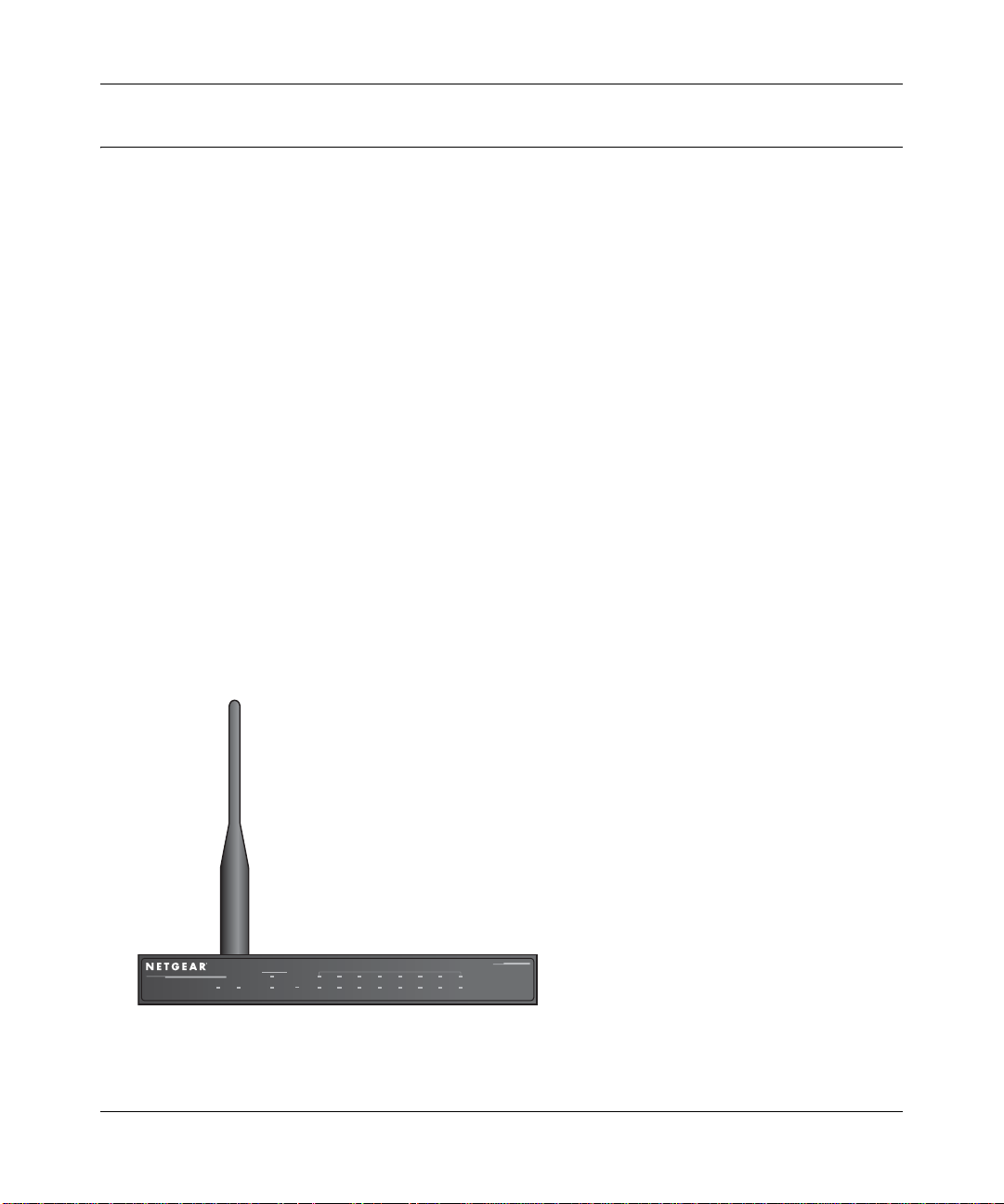
The Firewall’s Front Panel
The front panel of the FVM318 (Figure 1-1) contain s various status LEDs.
ProSafe Wireless VPN Security Firewall
Cable/DSL
PWR TEST
INTERNET
WLAN
LNK
ACT
Enable
LOCAL
12345678
Figure 1-1: FVM318 Front Panel
Introduction 1-5
100
LNK/ACT
MODEL
FVM318
Page 20

Reference Manual for the Model FVM318 Cable/DSL ProSafe Wireless VPN Security Firewall
You can use some of the LEDs to identify the status of the firewall and verify connections.
Table 1-1 describes each LED on the front pa nel of the firewall.
These LEDs are green when lit, except for the TEST LED, which is amber.
Table 1-1: LED Descriptions
Label Activity Description
POWER On Power is supplied to the firewall.
TEST On
Off
INTERNET
LINK On The port detected a link with the Internet WAN connection.
ACT On/Blinking Blinking indicates data transmission.
WLAN On The wireless interface is enabled.
LOCAL
100 On
Off
LINK/ACT On/Blinking The Local port has detected a link with a LAN connection.
The system is initializing.
The system is ready and running.
The Local port is operating at 100 Mbps.
Indicates data trans mi ssion at 10 Mbp s.
Blinking indicates data transmission.
1-6 Introduction
Page 21
Reference Manual for the Model FVM318 Cable/DSL ProSafe Wireless VPN Security Firewall
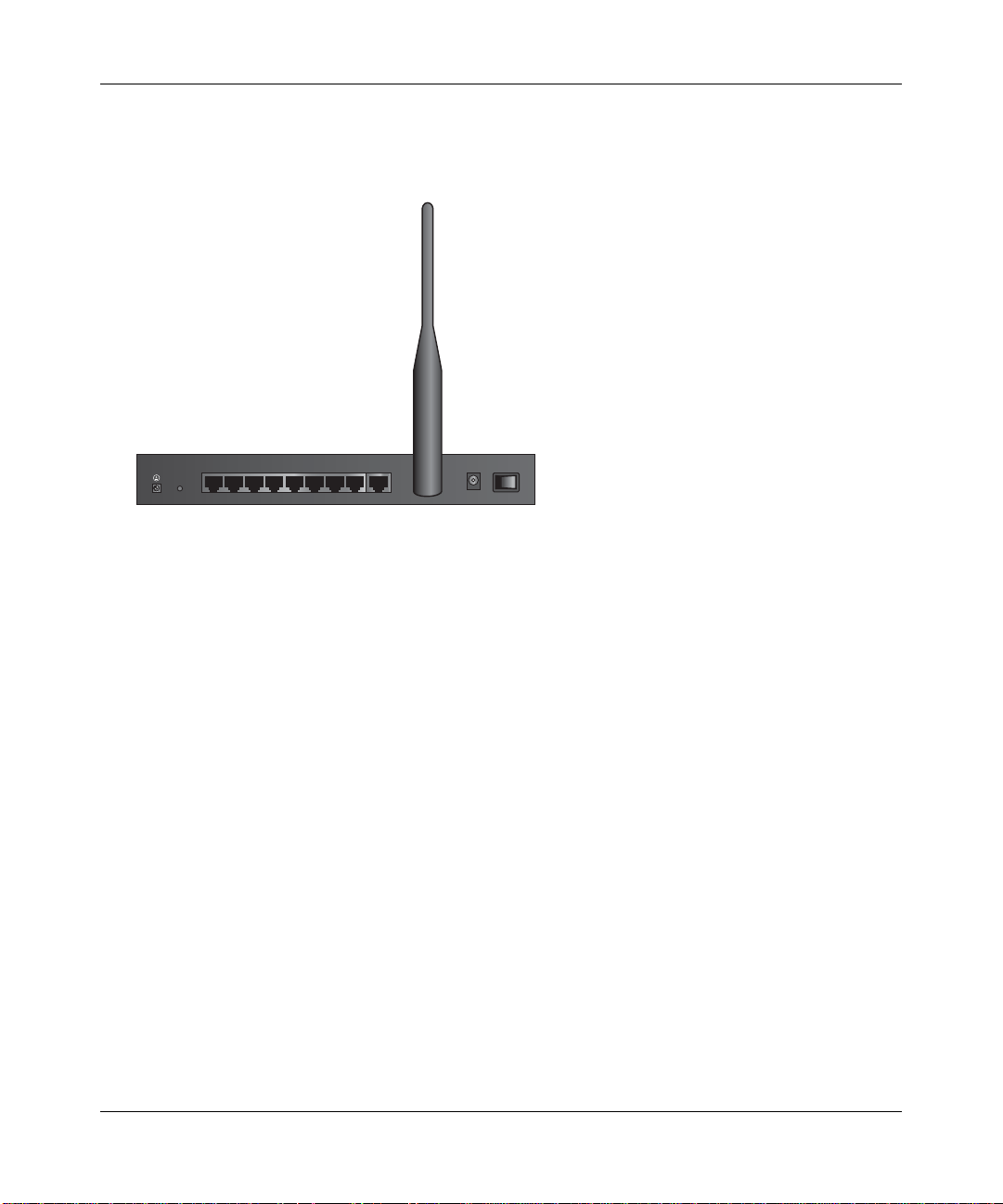
The Firewall’s Rear Panel
The rear panel of the FVM318 (Figure 1-2) contains the connections identified below.
LOCAL
10/100M
876543221
INTERNET
Figure 1-2: FVM318 Rear Panel
Viewed from left to right, the rear panel contains the following elements:
• Ground connector.
• Factory Default Reset push button.
• Eight Local Ethernet RJ-45 ports for connecting the firewall to the local computers.
• Internet WAN Ethernet RJ-45 port for connecting the firewall to a cable or DSL modem.
• Wireless antenna.
• AC power adapter input.
• Power switch.
12VDC O.5A
OFF ON
Introduction 1-7
Page 22

Reference Manual for the Model FVM318 Cable/DSL ProSafe Wireless VPN Security Firewall
1-8 Introduction
Page 23

Chapter 2
Connecting the Firewall to the Internet
This chapter describes how to set up the firewall on your Local Area Network (LAN), con nect to
the Internet, perform basic configuration of your FVM318 Cable/DSL ProSafe Wireless VPN
Security Firewall using the Setup Wizard, or how to manually configure your Internet connection.
What You Will Need Before You Begin
You need to prepare these three things before you begin:
1. Have active Internet service such as that provided by an cable or DSL broadband account.
2. Locate the Internet Service Provider (ISP) configuration information for your account.
3. Connect the firewall to a cable or DSL modem and a computer as explained below.
Cabling and Computer Hardware Requirements
To use the FVM318 firewall on your network, each computer must have an installed Ethernet
Network Interface Card
at 100 Mbps, you must use a Category 5
(NIC) and an Ethernet cable. If the computer will con nect to your net work
(CAT5) cable such as the one provided with your fire wall.
Network Configuration Requirements
The FVM318 includes a built-in Web Configuration Manager. To access the configuration menus
®
on the FVM318, your must use a Java
uploads such as Microsoft Internet Explorer or Netscape
using Internet Explor er 5.0 or Netsc ape Navigat or 4.7 or above. Free brows er programs are readily
available for Windows
For the initial connection to the Interne t and configuration of your firewall, you will need to
connect a computer to the firewal l which is set to automa ti cally get its TCP/IP configurati on fr om
the firewall via DHCP.
Note: For help with DHCP configuration, please refer to Appendix C, "Preparing Your Network".
Connecting the Firewall to the Internet 2-1
®
, Macintosh®, or UNIX®/Linux®.
-enabled web browser program which supports HTTP
®
Navigator. NETGEAR recommends
Page 24

Reference Manual for the Model FVM318 Cable/DSL ProSafe Wireless VPN Security Firewall
The cable or DSL modem broadb and access device mu st provid e a standard 10 Mbps (10BASE-T )
Ethernet interface.
Internet Configuration Requirements
Depending on how your ISP set up your Internet account, you will need one or more of these
configuration parameters to connect your firewall to the Internet:
• Host and Domain Names.
• ISP Login Name and Password.
• ISP Domain Name Server (DNS) Addresses.
• Fixed IP Address which is also known as Static IP Address.
Where Do I Get the Internet Configuration Parameters?
There are several ways you can gather the required Internet connection information.
• Your ISP provides all the information needed to connect to the Internet. If you cannot locate
this information, you can ask your ISP to provide it or you can try one of the options below.
• If you have a computer already connected using the active Internet access account, you can
gather the configuration information from that computer.
• For Windo ws® 95/98/ME, open the Network control panel, select the TCP/IP entry for the
Ethernet adapter, and click Properties. Record all the settings for each tab page.
• For Windows 2000/XP, open the Local Area Network Connecti on, select the TCP/IP entry
for the Ethernet adapter, and click Properties. Record all the settings for each tab page.
• For Macintosh® computers, open the TCP/IP or Network control panel. Record all the
settings for each section.
• You may also refer to the NETGEAR Router ISP Guide on the FVM318 Resource CD which
provides Internet connection information for many ISPs.
Once you locate your Internet configuration parameters, record them on the page below.
2-2 Connecting the Firewall to the Internet
Page 25

Reference Manual for the Model FVM318 Cable/DSL ProSafe Wireless VPN Security Firewall
Procedure 2-1: Record Your Internet Connection Information
Print this page. Fill in the configuration parameters from your Internet Service Provider (ISP).
ISP Login Name: The login name an d pas swor d ar e ca se s ens itive and must be entered exact ly as
given by your ISP. Some ISPs use your full e -mail addr ess as the l ogin na me. The Ser vice Na me is
not required by all ISPs. If you connect using a login name and password, then fill in the
following:
Login Name: ______________________________
Password: ____________________________
Service Name: _____________________________
Fixed or Static IP Address: If you have a static IP address, record the following information. For
example, 169.254.141.148 could be a valid IP address.
Fixed or Static Internet IP Address: ______
. ______ . ______ . ______
Subnet Mask: ______ . ______ . ______ . ______
Gateway IP Address: ______ . ______ . ______ . ______
ISP DNS Se rver Addresses: If you were given DNS server addresses, fill in the following:
Primary DNS Server IP Address: ______
. ______ . ______ . ______
Secondary DNS Server IP Address: ______ . ______ . ______ . ______
Host and Domain Names: Some ISPs use a specific host or domain name like CCA7324-A or
home. If you haven’t been given host or domain names, you can use the following examples as a
guide:
• If your main e-mail account with your ISP is aaa@yyy.com, then use aaa as your host name.
Your ISP might call this your account, user, host, computer, or system name.
• If your ISP’s mail server is mail.xxx.yyy.com, then use xxx.yyy.com as the domain name.
ISP Host Name: _________________________ ISP Domain Name: _______________________
For Wireless Acce ss: For configuration of the wireless network, record the following:
Wireless Network Name (SSID): __________________
Encryption (circle one): WEP 64, WEP 128, or IPSec
WEP or IPSec key: ____________________
Connecting the Firewall to the Internet 2-3
Page 26
Reference Manual for the Model FVM318 Cable/DSL ProSafe Wireless VPN Security Firewall
Connecting the FVM318 to Your LAN
This section provides instructions for connecting the FVM318 Cable/DSL ProSafe Wireless VPN
Security Firewall to your LAN. The Resource CD included with your firewall contains an
animated Installation Assistant to help you through this procedure.
Procedure 2-2: Conn ecting the Firewall to Your LAN
There are three steps to connecting your firewall:
1. Connect the firewall to your network.
2. Log in to the firewall.
3. Connect to the Internet.
Follow the steps below to connect your firewall to your network.
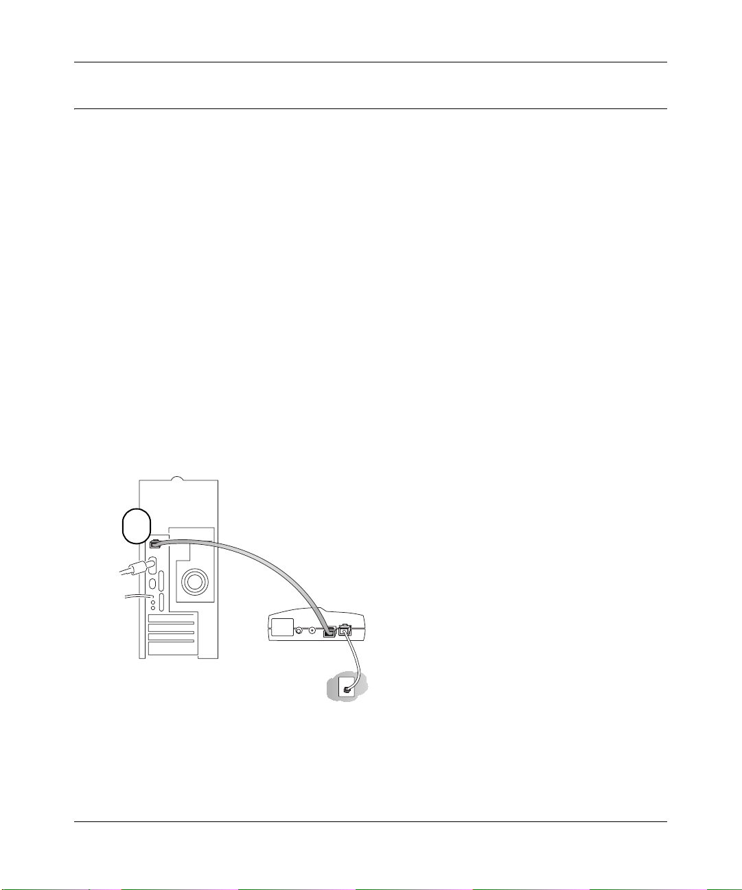
1. Connect the firewall.
a. Turn off your computer and cable or DSL Modem.
b. Disconnect the Ethernet cable (A) from your computer which connects to the modem.
A
Cable or DSL modem
Figure 2-1: Disconnect the cable or DSL Modem
2-4 Connecting the Firewall to the Internet
Page 27

Reference Manual for the Model FVM318 Cable/DSL ProSafe Wireless VPN Security Firewall
c. Connect the Ethernet cable (A) from the modem to the FVM318’s Internet port.
A
LOCA L
10/100M
876543221INTERNET
Model FVM318 Wireless VPN Security Firewall
Cable or DSL modem
12VDCO.5A
OFF ON
Figure 2-2: Connect the cable or DSL Modem to the firewall
d. Connect the Ethernet cable (B) which came with the firewall from a local port on the
router to your computer.
B
LOCA L
10/100M
876543221INTERNET
Model FVM318 Wireless VPN Security Firewall
Cable or DSL modem
Figure 2-3: Connect the computers on your network to the firewall
Connecting the Firewall to the Internet 2-5
12VDCO.5A
OFF ON
Page 28
Reference Manual for the Model FVM318 Cable/DSL ProSafe Wireless VPN Security Firewall
Note: The FVM318 firewall incorporates Auto UplinkTM technology. Each LAN Ethernet
port will automatically sense whether the cable plugged into the port should have a
'normal' connection (e.g. connecting to a PC) or an 'uplink' connection (e.g. connecting to
a switch or hub). That port will then configure itself to the correct configuration. This
feature also eliminates the need to worry about crossover cables, as Auto Uplink will
accommodate either type of cable to make the right connection.
e. Turn on the modem and wait about 30 seconds for the lights to stop blinking.
f. Turn on the firewall and wait for the Test light to stop blinking.
g. Now, turn on your computer. If you usually run software to log in to your Internet
connection, do not run that software.
h. Now that the modem, firewall, and computer are tur ned on, verify the following:
• When the firewall was first turned on, the PWR light went on, the TEST light turned
on within a few seconds, and then went off after approximately 10 seconds.
• The firewall’s INTERNET LINK light is lit, indicating a link has been established to
the cable or DSL modem.
• The firewall’s LOCAL LINK/ACT lights are lit for any computers connected to it.
2. Log in to the firewall.
Note: T o conn ect to the fi rewall, your comput er needs to be conf igured to obt ain an IP addre ss
automatically via DHCP. Please refer to
Appendix C, "Preparing Your Network" for
instructions on how to do this.
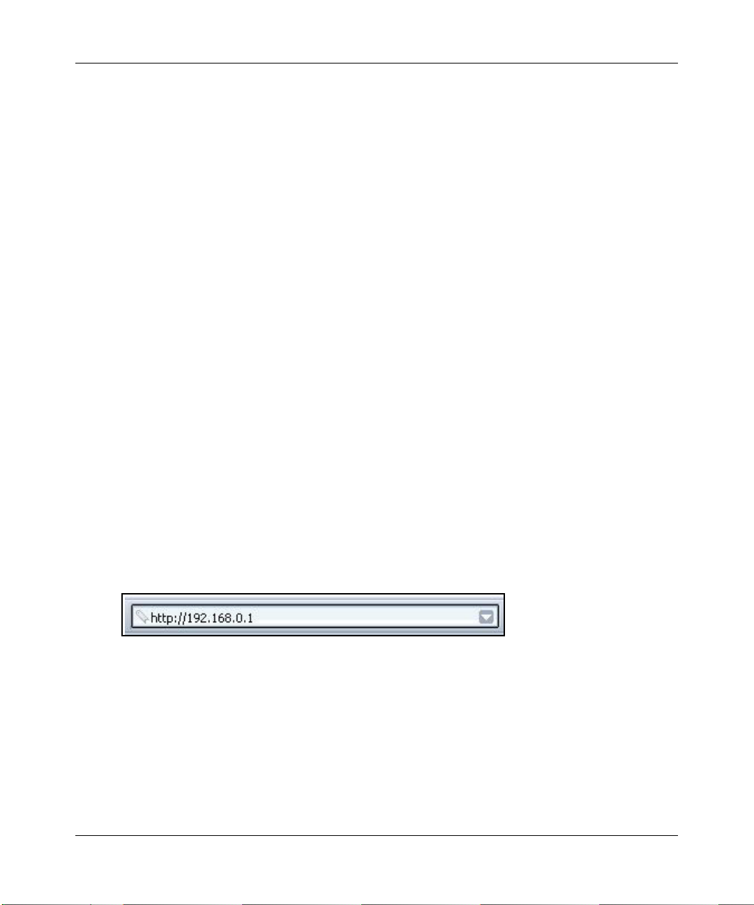
a. Log in to the firewall at its default address of http://192.168.0.1 using a browser like
Internet Explorer or Netscape
Figure 2-4: Log in to the firewall.
2-6 Connecting the Firewall to the Internet
®
Navigator.
Page 29
Reference Manual for the Model FVM318 Cable/DSL ProSafe Wireless VPN Security Firewall
A login window opens like the one shown below.
Figure 2-5: Login window
b. For security reasons, the firewall has its own user name and password. When prompted,
enter
admin for the firewall user name and password for the firewall password, both in
lower case letters.
Note: The user name and password are not the same as any user name or password you
may use to log in to your Internet connection.
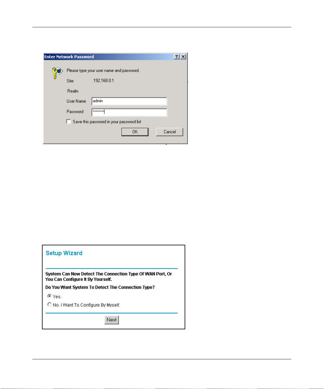
3. Connect to the Internet
Figure 2-6: Setup Wizard
Connecting the Firewall to the Internet 2-7
Page 30

Reference Manual for the Model FVM318 Cable/DSL ProSafe Wireless VPN Security Firewall
a. You are now connected to the firewall. If you do not see the menu above, click the Setup
Wizard link on the upper left of the main menu.
b. Click Next and follow the steps in the Setup Wizard for inputting the configuration
parameters from your ISP to connect to the Internet.
Note: If you choose not to use the Setup Wizard, you can manually configure your
Internet connection settings by following the procedure
“Manually Configuring Your
Internet Connection” on page 2-12.
Unless your ISP assigns your configuration automatically via DHCP, you will need the
configuration p arame ters from y our ISP as you r eco rded t hem p revio usly i n “ Record Your
Internet Connection Information” on page 2-3.
c. When the firewall successfu lly de tect s an ac tive I nt ernet servi ce, th e Se tup Wizard report s
which connection type it discovered, and displays the appropriate configuration menu. If
the Setup Wizard finds no connection, you will be prompted to check the physical
connection between your firewall and the cable or DSL line.
d. The Setup Wizard will report the type of connection it finds. The options are:
• Connections which require a login using protocols such as PPPoE.
Note: Customers in Austria or Australia who use Internet accounts which require
login will have to use the manual configuration procedure,
“Manually Configuring
Your Internet Connection” on page 2-12. The Smart Wizard will not detect these
options.
• Connections which use dynamic IP address assignment.
• Connections which use fixed IP address assignment.
The procedures for filling in the configuration menu for each type of connection follow
below.
2-8 Connecting the Firewall to the Internet
Page 31

Reference Manual for the Model FVM318 Cable/DSL ProSafe Wireless VPN Security Firewall
PPPoE Wizard-Detected Option
If the Setup Wizard discovers that your ISP uses PPPoE, you will see this menu:
Figure 2-7: Setup Wizard menu for PPPoE accounts
• Enter the Account Na me, Domain Name, Logi n, and passwo rd as provi ded by your ISP. These
fields are case sensit ive. The fire wall will try to disc over the domai n automatica lly if you leave
the Domain Name blank. Otherwise, you may need to enter it manually.
• To change the login timeout, enter a new value in minutes. This determines how long the
firewall keeps the Internet connection active after there is no Internet activity from the LAN.
Entering a timeout value of zero means never log out.
Note: You no longer need to run the ISP’s login program on your PC in order to access the
Internet. When you start an Internet application, your firewall will automatically log you in.
• If you know that your ISP does not automatically transmit DNS addresses to the firewall
during login, select “Use these DNS servers” and enter the IP address of your ISP’s Primary
DNS Server. If a Secondary DNS Se rver address is available, enter it also .
Note: If you enter DNS addresses, restart your computers so that these settings take effect.
• Click Apply to save your settings.
• Click Test to verify that your Internet connection works. If the NETGEAR website does not
appear within one minute, refer to
Connecting the Firewall to the Internet 2-9
Chapter 8, Troubleshooting.
Page 32

Reference Manual for the Model FVM318 Cable/DSL ProSafe Wireless VPN Security Firewall
Dynamic IP Wizard-Detected Option
If the Setup W i zar d dis covers that your ISP uses Dynamic IP assi gnme nt, you will see thi s menu:
Figure 2-8: Setup Wizard menu for Dynamic IP address accounts
• Enter your Account Name (may also be called Host Name) and Domain Name. These
parameters may be ne cessary to acc ess your ISP’s services such as mai l or news servers . If yo u
leave the Domain Name field blank, the firewall try to discover the domain. Otherwise, you
may need to enter it manually.
• If you know that your ISP does not automatically transmit DNS addresses to the firewall
during login, select Use these DNS servers and enter the IP address of your ISP’s Primary
DNS Server. If a Secondary DNS Se rver address is available, enter it also .
Note: If you enter DNS addresses, restart your computers so that these settings take effect.
• Click Apply to save your settings.
• Click Test to test your Internet connection. If the NETGEAR website does not appear within
one minute, refer to
2-10 Connecting the Firewall to the Internet
Chapter 8, Troubleshooting.
Page 33

Reference Manual for the Model FVM318 Cable/DSL ProSafe Wireless VPN Security Firewall
Fixed IP Account Wizard-Detected Option
If the Setup Wizard discovers that your ISP uses Fixed IP assignment, you will see this menu:
Figure 2-9: Setup Wizard menu for Fixed IP address accounts
• Fixed IP is also called Static IP. Enter your assigned IP Address, Subnet Mask, and the IP
Address of your ISP’s gateway router. This information should have been provided to you by
your ISP. You will need the configuration parameters from your ISP you recorded in “Record
Your Internet Connection Information” on page 2-3.
• Enter the IP address of your ISP’s Primary and Secondary DNS Server addresses.
Note: Afte r completing the DNS confi guration, re start the com puters on your network so that
these settings take effect.
• Click Apply to save the settings.
• Click Test to test your Internet connection. If the NETGEAR website does not appear within
one minute, refer to
Connecting the Firewall to the Internet 2-11
Chapter 8, Troubleshooting.”
Page 34

Reference Manual for the Model FVM318 Cable/DSL ProSafe Wireless VPN Security Firewall
Manually Configuring Your Internet Connection
You can manually configure your firewall using the menu below, or you can allow the Setup
Wizard to determine your configuration as described in the previous section.
ISP Does Not Require Login
ISP Does Require Login
Figure 2-10: Browser-based configuration Basic Settings menus
2-12 Connecting the Firewall to the Internet
Page 35

Reference Manual for the Model FVM318 Cable/DSL ProSafe Wireless VPN Security Firewall
Procedure 2-3: Configuring the Internet Connection Manually
You can manually configure the firewall using the Basic Settings menu shown in Figure 2-10
using these steps:
1. Log in to the firewall at its default address of http://192.168.0.1 using a browser like Internet
Explorer or Netscape
2. Click the Basic Settings link under the Setup section of the main menu.
3. If your Internet connection does not require a login, click No at the top of the Basic Settings
menu and fill in the settings according to the instructions below. If your Internet connection
does require a login, click Yes, and skip to step 3.
a. Enter your Account Name (may also be called Host Name) and Domain Name.
These parameters may be necessary to access your ISP’s services such as mail or news
servers.
b. Internet IP Address:
If your ISP has assigned you a permanent, fixed (static) IP address for your PC, select
“Use static IP address”. Enter the IP address that y our ISP assigned. Also enter the
netmask and the Gateway IP address. The Gateway is the ISP’s router to which your
firewall will connect.
®
Navigator.
c. Domain Name Server (DNS) Address:
If you know that your ISP does not automatically transmit DNS addresses to the firewall
during login, select “Use these DNS servers” and enter the IP address of your ISP’s
Primary DNS Server. If a Secondary DNS Server address is available, enter it also.
Note: After completing the DNS configuration, restart the computers on your network so
that these settings take effect.
d. Gateway’s MAC Address:
This section det er mine s the Ethernet MAC address t hat wi ll be used by the firewall on the
Internet po rt. Some ISPs will register the Ethernet MAC addres s of the network interface
card in your PC when your account is fir st open ed. They wil l then only acce pt tra f fic f rom
the MAC address of that PC. This feature allows your firewall to masquerade as that PC
by “cloning” its MAC address.
To change the MAC address, select “Use this Computer’s MAC address.” The firewall
will then capture and use the MAC addres s of the PC t hat you are now us in g. You must be
using the one PC that is allowed by the ISP. Or, select “Use this MAC address” and enter
it.
e. Click Apply to save your settings.
Connecting the Firewall to the Internet 2-13
Page 36

Reference Manual for the Model FVM318 Cable/DSL ProSafe Wireless VPN Security Firewall
4. If your Internet connectio n does require a login, fi ll in the settings according to the instruc tions
below. Select Yes if you normally must launch a login program such as Enternet or WinPOET
in order to acc ess the Internet.
Note: After you finish setting up your firewall, you will no longer need to launch the ISP’s
login program on your PC in order to access the Internet. When you start an Internet
application, your firewall will automatically log you in.
a. Select your Internet service provider from the drop-down list.
Figure 2-11: Basic Settings ISP list
b. The screen will change according to the ISP settings requirements of the ISP you select.
c. Fill in the parameters for your ISP according to th e W izard-detect ed procedures starting on
page 2-9.
d. Click Apply to save your settings.
2-14 Connecting the Firewall to the Internet
Page 37

Chapter 3
Wireless Configuration
This chapter describes how to configure the wireless features of your FVM318 Cable/DSL
ProSafe Wireless VP N Security Firewall.
Considerations For A Wireless Network
In planning your wireless network, you should consider the level of security required. You should
also select the physical placement of your firewall in order to maximize the network speed. For
further information on wireless networking, refer to “Wireless Networking” in Appendix B,
“Network, Routing, Firewall, an d Wireless Basics.”
Observe Performance, Placement and Range Guidelines
The operating distance or range of your wireless connection can vary significantly based on the
physical placement of the wireless firewall. The latency, data throughput performance, and
notebook power consumption properties vary depending on your configuration choices.
Note: Failure to follow these guidelines can result in significant performance
degradation or inability to wirelessly connect to the router. For complete range/
performance specifications, please see Appendix A, “Technical Specifications.”
For best results, place your firewall:
• Near the center of the area in which your PCs will operate.
• In an elevated location such as a high shelf where the wirelessly connected PCs have
line-of-sight access (even if through walls).
• Away from sources of interference, such as PCs, microwaves, and 2.4 GHz cordless phones.
• Away from large me tal surfaces.
The time it takes to establish a wireless connection can vary depending on both your security
settings and placement. WEP and IPSec connections can take slightly longer to establish. Also,
WEP encryption can consume more battery power on a notebook PC but IPSec can use less.
Wireless Configuration 3-1
Page 38

Reference Manual for the Model FVM318 Cable/DSL ProSafe Wireless VPN Security Firewall
Implement Appropriate Wireless Security
Unlike wired network data, your wireless data transmissions can extend beyond your walls and
can be received by anyone with a compatible adapter. For this reason, use the security features of
your wireless equipment.
Note: Indoors, computers can connect over 802.11b wireless networks at a
maximum range of up to 500 feet. Such distances can allo w for others o utside o f your
immediate area to access your network. It is important to take appropriate steps to
secure your network from unauthorized access. The FVM318 firewall provides highly
effective security features which are covered in detail in this chapter. Deploy the
security features appropriate to your needs.
FVM318 Wireless
Data Security Options
Range: Up to 500 Feet
Cable/DSL
ProSafeWirelessVPNSecurityFirewall
FVM318
INTERNET LOCAL
LNK
PWR TEST
ACT
WLAN
Enable
12345678
MODEL
FVM318
100
LNK/ACT
1) Open System: Easy but no security
2) MAC Access List: No data security
3) WEP: Limited securit y but performance impact
4) IPSec (VPN): Highly secure, more reliable, and better performance
Figure 3-1: FVM318 wireless data security options
Restricting access by MAC address filtering adds an obstacle against unwanted access to your
network, but the data broadcast over the wireless link is fully exposed. To block a determined
eavesdropper, you should use one of the data encryption options of the firewall. Wired Equivalent
Privacy (WEP) data encryption provides some security. However, a determined intruder can
compromise WEP, there may be degradation of the data throughput on the wireles s link, and WEP
configurations can be le ss relia ble. Unique to t he FVM318, you can use the highly secur e, reliabl e,
high performance IPSec VPN communications protocols for your wireless connection.
3-2 Wireless Configuration
Page 39

Reference Manual for the Model FVM318 Cable/DSL ProSafe Wireless VPN Security Firewall
Understanding Wireless Settings
T o configure the Wireless settings of your firewall, click the Wireless link in the main menu of the
browser interface. The Wireless Settings menu will appear, as shown below.
Figure 3-2: Wireless Settings menu
Wireless Ne t work Setting s
The Wireless Settings menu sections are discussed below.
• Name (SS ID). The Serv ice Set Identification is also known as the wireless ne twork name.
Enter a value of up to 32 alphanumeric characters. Wireless access point devices like the
FVM318 broadcast the SSID and any other wireless node in the same area can receive this
SSID. This is not a security feature. It is simply the name of the wireless network. In a s etting
where there is more than one wireless network, different wireless network names provide a
means for separating the traffic. Any device you want to participate in this wireless network
will need to use this SSID. The FVM318 de fault SSID is: Wireless.
• Region. This field ident ifie s the region where the FVM318 can be used. It may not be lega l to
operate the wireless features of the firewall in a region other than one of those identified on
this drop-down list.
• Channel. This field determines which operating frequency will be used. It should not be
necessary to change the wirele ss channel u nless y ou notice i nterfer ence prob lems with ano ther
nearby access point. For more information on the wireless channel frequencies please refer to
“Wireless Channel Selection” on page B-18.
Wireless Configuration 3-3
Page 40

Reference Manual for the Model FVM318 Cable/DSL ProSafe Wireless VPN Security Firewall
Restricting Access Based on the Wireless Card Access List
Figure 3-3: Wireless Card Access List menu
This settin g determines which hardware devices will be allowed to connec t to the firewa ll.
• Everyone. The FVM318 will not restrict wireless access based on MAC address.
• Trusted PCs Only. Requires specifying the MA C address in the list if trusted PC MAC
addresses before any device connecting wirelessly to the FVM318 will be allowed to connect
to the firewall.
Choosing Authentication and Security Encryption Methods
Figure 3-4: Encryption Strength
Note: Whichever Security Encryption settings you choose for the FVM318 will be
enforced for all wireless connections. For example, if you choose IPSec, then the only
wireless connections allowed will be those established according to the VPN tunnel
settings you specify.
Automatic Authentication Scheme Selection
The FVM318 automatically selects the wireless appropriate authentication scheme based on the
encryption strength you choose.
• For WEP encryption, the FVM318 will enforce the shar ed key wireless au thenticati on scheme.
• For IPSec, the FVM318 will enforce the IPSec pre-shared key authentication scheme.
• For Disable, the FVM318 will use the Open System authentication scheme.
3-4 Wireless Configuration
Page 41

Reference Manual for the Model FVM318 Cable/DSL ProSafe Wireless VPN Security Firewall
If your wireless adapter requires you to configure an authentication scheme, set it accordingly.
Please refer to “Authentication and WEP Encryption” on page B-13 for a full explanation of each
of these options, as defined by the IEEE 802.11b wireless communication standard.
Encryption Strength Choices
Choose the encryption strength from the drop-down list.
Disable
No encryption will be applied. This setting is useful for troubleshooting your wireless
connection, but leaves your wireless data fully exposed.
IPSec
Selecting IPSec displays the IPSec connection list. Click Add to configure a new IPSec
connection. To edit an existing connecti on, cl ick t he ra dio butt on next to the c onne ction on th e li st,
then click Edit. The IPSec settings screens are shown below.
IPSec Main and Aggressive Mode Settings
Figure 3-5: IPSec main or aggressive mode settings
• Choose Aggressive or Main Mode. Aggressive Mode is the default. Aggressive Mode is
required when you use the SafeNet SoftRemote Basic VPN Client for Windows which is
included on the FVM318 Resource CD.
• Select the Encryption Protocol.
Wireless Configuration 3-5
Page 42

Reference Manual for the Model FVM318 Cable/DSL ProSafe Wireless VPN Security Firewall
Figure 3-6: IPSec encryption protocol
DES is the least strong and AES - 256 is the strongest. AES - 256 is the default. The SafeNet
SoftRemote Basic VPN Client for Windows requires either 3DES or AES - 256.
— DES - The Data Encryption Standard (DES) processes input data that is 64 bits wide,
encrypting these values using a 56 bit key. Faster but less secure than 3DES or AES.
— 3DES - (Triple DES) achieves a higher level of se curity by enc rypti ng the data t hree t imes
using DES with three different, unrelated keys.
— AES - 128, - 192, or - 256. Most secure. Advanced Encryption Standard, a symmetric
128-bit block data e ncryption techniqu e. It is an itera ted block cipher with a variabl e block
length and a variable key length. The block length and the key length can be
independently specified to 128, 192 or 256 bits.The U.S government adopted the
algorithm as its encryption technique in October 2000, replacing the DES encryption it
used. AES works at multiple network layers simultaneously.
Once you have filled in the FVM318 settings, configure the wireless client accordingly.
64 or 128 bit WEP When 64 Bit WEP or 128 Bit WEP is selected, WEP encryption will be applied.
Figure 3-7: Encryption Strength
3-6 Wireless Configuration
Page 43

Reference Manual for the Model FVM318 Cable/DSL ProSafe Wireless VPN Security Firewall
WEP provides some degree of privacy, but can be defeated without great difficulty. If WEP is
enabled, you can manually or automatically program the four data encryption keys. These values
must be identical on all PCs and access points in your network.
Figure 3-8: 64 or 128 bit WEP encryption strength
Please refer to “Overview of WEP Parameters” on page B-16 for a full explanation of each of
these options, as defined by the IEEE 802.11b wireless communication standard.
There are two methods for creating WEP encryption keys:
• Passphrase. Enter a word or group of printable characters in the Passphrase box and click the
Generate button.
• Manual. 64-bit WEP: Enter 10 hexadecimal digits (any combination of 0-9, a-f, or A-F).
128-bit WEP: Enter 26 hexadecimal digits (any combination of 0-9, a-f, or A-F).
Clicking the radio button selects which of the four keys will be active.
Procedure 3-1: Set Up and Test Basic Wireless Connectivity
Follow the instructions below to set up and test basic wireless connectivity. Once you have
established basic wireless connectivity, you can enable security settings appropriate to your needs.
Wireless Configuration 3-7
Page 44

Reference Manual for the Model FVM318 Cable/DSL ProSafe Wireless VPN Security Firewall
1. Log in to the FVM318 fi rewall at its def ault LAN addre ss of http://192.168.0.1 with its d efault
user name of admin and default password of password, or using whatever LAN address and
password you have set up.
2. Click the Wireless Settings link in the main menu of the FVM318 firewall.
Figure 3-9: Wireless Settings menu
3. Choose a suitable descriptive name for the wireless network name (SSID). In the SSID box,
enter a value of up to 32 alphanumeric characters. The defaul t SSID is Wireless.
Wireless access point devices like the FVM318 broadcast the SSID and any other wireless
node in the same area can receive this SSID. This is not a security feature. It is simply the
name of the wireless network. In a setting where there is more than one wireless network,
different wireless network names provide a means for separating the traffic. Any device you
want to participate in this wireless network will need to use this SSID.
Note: The SSID of any wireless access adapters must match the SSID you configure in the
FVM318 Cable/DSL ProSafe Wireless VPN Security Firewall. If they do not match, you will
not get a wi reless connection to the FVM318.
4. Set the Region. Select the region in which the wireless interface will operate.
5. Set the Channel. The default channel is 6.
This field determines which operating frequency will be used. It should not be necessary to
change the wireless channel unless you notice interference problems with another nearby
wireless router or access point. Select a channel that is not being used by any other wireless
networks within several hundred feet of your firewall. For more information on the wireless
channel frequencies please refer to
6. For initial configuratio n and test, leave the Wireless Card Access List set to “Everyone” and
“Wireless Channel Selection” on page B-18.
the Encryption Strength set to “Disabled.”
7. Click Apply to save your changes.
3-8 Wireless Configuration
Page 45

Reference Manual for the Model FVM318 Cable/DSL ProSafe Wireless VPN Security Firewall
Note: If you are configuring the firewall from a wireless PC and you change the
firewall’s SSID, cha nnel, or security settings , you will lose your wireless connection
when you click on Apply. You must then change the wireless settings of your PC to
match the firewall’s new settings.
8. Configure and test your PCs for wireless connectivity.
Program the wireless adapter of your PCs to have the same SSID and channel that you
configured in the router. Check that they have a wireless link and are able to obtain an IP
address by DHCP from the firewall.
Once your PCs have basic wireless connectivity to the firewall, then you can configure the
advanced wireless security functions of the firewall.
Procedure 3-2: Restrict Wireless Access by MAC Address
To restrict access based on MAC addresses, follow these steps:
1. Log in to the FVM318 fi rewall at its def ault LAN addre ss of http://192.168.0.1 with its d efault
user name of admin and default password of password, or using whatever LAN address and
password you have set up.
2. Click the Wireless Settings link in the main menu of the FVM318 firewall.
3. From the W i re less Settings menu, clic k th e Trusted PCs but to n to display the W i reless Access
menu shown below.
Figure 3-10. Wireless Access menu
Wireless Configuration 3-9
Page 46

Reference Manual for the Model FVM318 Cable/DSL ProSafe Wireless VPN Security Firewall
4. Enter the MAC address of the authorized PC. Enter a descriptive nam e for the PC in th e
Device Name field. The MAC address is usua lly pr inted on the wir eless card, or it may appea r
in the firewall’s “Attached Devices” DHCP table.
Note: You can copy and pa ste t he M AC ad dresses from the fire wal l’s Attached Devices menu
into the MAC Address box of this menu. To do this, configure each wireless PC to obtain a
wireless link to the firewall. The PC should then appear in the Attached Devices menu.
5. Click Add to save your entry.
6. Click Back t o return to the Wireless Settings menu
7. Be sure that the Trusted PCs only radio button is selected, then click Apply.
To edit a MAC address from the table, click on it to select it, then click the Edit or Delete button.
Note: When configuring the firewall from a wireless PC whose MAC address is not in
the Trusted PC list, if you select Trusted PCs only, you will lose your wireless
connection when you cl ick on Appl y. You must then access the firewall from a wire d PC
to make any further changes.
Procedure 3-3: Configur e WEP
To configure WEP data encryption, follow these steps:
1. Log in to the FVM318 fi rewall at its def ault LAN addre ss of http://192.168.0.1 with its d efault
user name of admin and default password of password, or using whatever LAN address and
password you have set up.
2. Click the Wireless Settings link in the main menu of the FVM318 firewall.
3-10 Wireless Configuratio n
Page 47

Reference Manual for the Model FVM318 Cable/DSL ProSafe Wireless VPN Security Firewall
3. From the Security Encryption menu drop-down list, select the WEP encryption type you will
use.
Figure 3-11. Wireless Settings encryption menu
4. You can manually or automatically program the four data encryption keys. These values must
be identical on all PCs and Access Points in your network.
• Automatic - Enter a word or group of printable characters in the Passphrase box and click
the Generate button. The four key boxes will be automatically populated with key values.
• Manual - Enter ten hexadecimal digits (any combination of 0-9, a-f, or A-F)
Select which of the four keys will be active.
Please refer to “Overview of WEP Parameters” on page B-16 for a full explanation of each of
these options, as defined by the IEEE 802.11b wireless communication standard.
5. Click Apply to save your settings.
Note: When configuring the f irewall from a wirel ess PC, if you confi gure WEP setti ngs,
you will lose your wireless connection when you click on Apply. You must then either
configure your wireless adapter to match the firewall WEP settings or access the
firewall from a wired PC to make any further changes.
Wireless Configuration 3-11
Page 48

Reference Manual for the Model FVM318 Cable/DSL ProSafe Wireless VPN Security Firewall
Configuring IPSec Wireles s Connections
Unique to the FVM318, you have the option of using the highly secure VPN communications
protocols over your wireless connection.
Wireless
VPN Tunnel
VPN client
software
Cable/DSL
ProSafeWirelessVPNSecurity Firewall
FVM318
INTERNET LOCAL
WLAN
LNK
PWR TEST
ACT
Enable
12345678
MODEL
FVM318
100
LNK/ACT
Figure 3-12. Configuring basic wireless IPSec VPN tunnel connections
To use the IPSec features of the FVM318, you must have VPN client software installed on your
PC. The SafeNet SoftRemote Basic VPN client software included on the FVM318 Resource CD
provides a simple and very easy way to set up wireless VPN connections to the FVM318.
However, it only works with FVM318 wireless connections.
If you prefer the flex ibi l it y of u sing one VPN client software program f o r bo th y our l ocal wireless
connections and remote VPN connections, then you should consider the SoftRemoteLT client
which lets you pic k from multipl e configu rations, depending o n whether y ou are conn ecting ove r a
local wireless link to the FVM318 or remotely over the Internet. Instructions for configuring the
SoftRemot e SoftRemote LT for local wireless VPN connections to the FVM318 can be found at
“Using SoftRemoteLT Instead of SoftRemote Basic” on page 3-17. Instructions for co nfiguring
the SoftRemote SoftRemoteLT for remote VPN connections over the Internet to the FVM318 can
be found at “PC to LAN VPN access from a PC to an FVM318” on page 5-9.
3-12 Wireless Configuratio n
Page 49

Reference Manual for the Model FVM318 Cable/DSL ProSafe Wireless VPN Security Firewall
Procedure 3-4: Configure Basic IPSec Wireless Connections
The SafeNet SoftRemote Basic VPN client installer program is on the FVM318 Resource CD.
Observe the following guidelines when using the SafeNet SoftR emote Basic VPN client:
• The SoftRemote Basic client requires Windows 95 or later.
• The SoftRemote Basic client may not be compatible with other VPN clients. In this case
you must uninstall the other client before installing SoftRemote Basic.
• If your PC will also be used for remote VPN connections, you should use the full version
of SafeNet SoftRemote, not the Basic version.
1. Configure the FVM318 settings.
a. Log in to the FVM318 at http://192.168.0.1 with its default user name of admin and
default password of password, or using whatever user name, password you have set up.
b. Click the Wireless link in the main menu Setup section to display the menu shown below.
Figure 3-13. Wireless Settings menu, IPSec selected
c. Click the Encryption Strength dro p-d own lis t box and sel ect IPSe c. The Wireless Setti ngs
menu will change to display the list of IPSec connections, as shown in
Wireless Configuration 3-13
Figure 3-13:
Page 50

Reference Manual for the Model FVM318 Cable/DSL ProSafe Wireless VPN Security Firewall
d. Click Add to display the IPSec client setting menu, as shown below.
Figure 3-14. IPSec Client Settings menu
e. Enter a descriptive name for this PC in Connection Name. This name is for your
convenience only, and is not used in the VPN negotiation.
f. E nter the user name. An email address is an easy to remember user name.
g. Enter a Pre-Shared Key value for this connection.
h. Use the default Aggressive Mode and AES - 256 settings.
2. Install the SafeNet SoftRemote Basic VPN client software.
Note: Before installing the SafeNet SoftRemote Basic VPN Client software, be sure to
turn off any virus protection or firewall software you may be running on your PC.
a. Place the FVM318 Resource CD in your CD drive.
If the CD does not autostart, double click on the INDEX.HTM file on the CD.
b. Install the SafeNet SoftRemote Basic VPN client.
After installation, a SafeNet icon shown below will appear in the taskbar tray of your PC.
Figure 3-15. SafeNet system tray icon with disabled indicator
3-14 Wireless Configuratio n
Page 51

Reference Manual for the Model FVM318 Cable/DSL ProSafe Wireless VPN Security Firewall
At this point, the Sa feNet i con has a diago nal re d bar th rou gh it, indi catin g th at the VPN clien t
is currently disabled.
3. Configure the SoftRemote Basic VPN Client.
a. In the taskbar tray, right-click on the SafeNet icon and select Edit Security Poli cy in the
VPN client task menu, as shown below.
Figure 3-16. SafeNet system tray icon menu
The VPN client Security Policy menu will appear as shown below.
SafeNet Basic Client Configuration
FVM318 IPSec Settings
Figure 3-17. SafeNet basic configuration menu
Wireless Configuration 3-15
Page 52

Reference Manual for the Model FVM318 Cable/DSL ProSafe Wireless VPN Security Firewall
b. In most cases, you can leave the IPSec Gateway as “LAN Gateway”, which indicates the
firewall. If you are no t us ing the fire wall as your net work ’s default ga teway, change IPSec
Gateway to indicate either the IP Address or the network name of the firewall.
c. Enter the User Name and the Pre-Shared Key value that you programmed for this PC in
the firewal l’s IPSec C l ient Setting s menu.
d. Click OK.
e. In the taskbar tray, right-click on the SafeNet icon and select Activate Security Pol icy in
the task menu. The SafeNet icon will now appear without the red bar, as shown below.
Figure 3-18. SafeNet system tray icon showing enabled condition
4. Test the SoftRemote Basic VPN Connection.
To check the VPN Connection, you can initiate a request from the PC to the firewall. The
simplest method is to ping from the PC to the firewall, as shown below:
a. On the Windows taskbar, click the Start button, and then click Run.
b. Type ping -t 192.168.0.1 , and then click OK.
Figure 3-19. Run Ping from Windows Start Menu
3-16 Wireless Configuratio n
Page 53

Reference Manual for the Model FVM318 Cable/DSL ProSafe Wireless VPN Security Firewall
This will cause a con tinuous ping t o be s ent to th e firewal l. Within thirt y second s, the pin g
response should change from timed out to reply.
Figure 3-20. Ping results
At this point, the SafeNet tray icon should change to read on as shown below:
Figure 3-21. SafeNet system tray icon showing ON condition
c. Once the connection is established, you can open the browser of the PC and browse.
To view the firewall’s connection log, go to the Rout er Status menu and click on Wireless
VPN Log. The VPN client’s log is written to the text file isakmp.log, which can be found
in the direc tory in which the client is installed. Typically that directory is:
C:\PROGRAM FILES\SAFENET\SOFTREMOTEBASIC
Help is also available by right-clicking on the SafeNet taskbar icon and selecting Help.
Using SoftRemoteLT Instead of SoftRemote Basic
The SafeNet SoftRemote Basic VPN Client that is included with the firewall is only suitable for
establishing a local wireless IPSec connection with the FVM318 firewall. If your PC is mobile,
you may want to al so use it to connect t o your firewall over t he Internet from a remote location. In
that case you will need a full VPN Client. SafeNet’s SoftRemoteLT VPN Client (or another
version of SafeNet’s full client) will serve both purposes.
Note: Before installing the SafeNet SoftRemote Basic VPN Client software, be sure to
turn off any virus protection or firewall software you may be running on your PC.
Wireless Configuration 3-17
Page 54

Reference Manual for the Model FVM318 Cable/DSL ProSafe Wireless VPN Security Firewall
Procedure 3-5: Configuring the SoftRemoteLT Full Client
To configure a policy for a secure local wireless connection to the FVM318 firewall using the
SoftRemoteLT client, use the FVM318 configuration from “Configure Basic IPSec Wireless
Connections” on page 3-13 and follow procedure below for configuring the full VPN client.
1. Install the SafeNet SoftRemoteLT Full VPN Client
Note: If you have installed the SoftRemote Basic client, you must uninstall it before
installing SoftRemoteLT. During the uninstall process, you can choose to keep your
existing security policy, simplifying the configuration of SoftRemoteLT. In
SoftRemoteLT, you can conf igu re multi ple Sec urity Poli cies, such as a poli cy for se cure
local wireless connection to the FVM318 firewall and a policy for connecting remotely
from the Inte rnet.
2. Open the Security Policy Editor.
To launch the SoftRemoteLT client, click on the Windows Start button, then select Programs,
then SafeNet, then Security Policy Editor. The Security Policy Editor window will appear.
Figure 3-22. SafeNet Security Policy Editor
3. Create a VPN Connection.
3-18 Wireless Configuratio n
Page 55

Reference Manual for the Model FVM318 Cable/DSL ProSafe Wireless VPN Security Firewall
You will need to provide: A descriptive name for the connection; and the LAN address of the
FVM318 firewall.
a. From the Edit menu at the top of the Security Policy Editor window, click Add, then
Connection. A New Connection listin g will appear in the list of policies.
Figure 3-23. SafeNet Security Policy Editor new connection menu
b. Click and rename the New Connection list item to indicate that this is the polic y for your
local wireless connection, such as Wireless.
c. Select Secure on the right side of the Security Policy Editor window in the Connection
Security box.
d. Select IP Subnet in the ID Type menu.
e. Type 0.0.0.0 in the Subnet and Mask fields.
f. Select All in the Protocol menu to allow all traffic through the VPN tunnel.
g. Check Connect using Secure Gateway Tunnel.
h. Select Any in the ID Type menu below the checkbox.
i. Select Gateway IP Address in the box to the right of ID Type.
j. Enter the LAN IP Address of the FVM318 firewall in the lower right box (usually
192.168.0.1).
Wireless Configuration 3-19
Page 56

Reference Manual for the Model FVM318 Cable/DSL ProSafe Wireless VPN Security Firewall
4. Configure the Security Policy.
Note: These settings do not depend on your network configuration information.
a. In the Network Security Policy list on the lef t side of the Security Policy Editor window,
expand the new connection by double clicking its name or clicking on the “+” symbol.
My Identity and Security Policy subheadings should appear below the connection name.
b. Click on the Security Policy subheading to show the Security Policy menu.
Figure 3-24. SafeNet Security Policy Editor edit security policy menu
c. Select Aggressive Mode in the Select Phase 1 Negotiation Mode box.
d. Check the Enable Perfect Forward Secrecy (PFS) checkbox.
e. Select Diffie-Helman Group 2 for PFS Key Group.
f. Check the Enable Replay Detection checkbox.
5. Configure the VPN Client Identity
In this step, you will provide information about your client PC. You will need to provide:
• The User Name that you configured in the FVM318 firewall.
• The Pre-Shared Key that you configured in the FVM318 firewall.
3-20 Wireless Configuratio n
Page 57

Reference Manual for the Model FVM318 Cable/DSL ProSafe Wireless VPN Security Firewall
a. Click on My Identity in the Network Security Policy list on the left side of the Security
Policy Editor window.
Figure 3-25. SafeNet Security Policy Editor edit identity menu
b. Choose None in the Select Certificate menu.
c. Select Domain Name in the ID Type menu.
d. In the box below ID Type, enter the user name that you configured in the FVM318
firewall.
e. Select Disabled in the Virtual Adapter box.
f. In the Internet Interface box, select your wireless adapter or you may choose Any if you
will be switching between adapters or if you have only one adapter.
g. Click the Pre-Shared Key button.
h. Click the Enter Key button in the Pre-Shared Key dialog box.
i. Enter the Pre-Shared Key that you confi gured in the FVM318 f irewall and cl ick OK. Not e
that this field is case sensitive.
6. Configure VPN Client Authentication Proposal
Note: These settings do not depend on your network configuration information.
a. In the Network Security Policy list on the lef t side of the Security Policy Editor window,
expand the Security Policy heading by double clicking its name or clicking on the “+”
symbol.
Wireless Configuration 3-21
Page 58

Reference Manual for the Model FVM318 Cable/DSL ProSafe Wireless VPN Security Firewall
b. Expand the Authentication subheading by double clicking its name or clicking on the “+”
symbol. Then select Proposal 1 below Authentication.
c. Select Pre-Shar ed key in the A uthentication Method menu.
d. Select AES-256 in the Encrypt Alg menu. If your VPN cli ent does not offer this selection,
select Triple DES.
e. Select SHA-1 in the Hash Alg menu.
f. Select Seconds and enter 21600 in the SA Life menu.
g. Select Diffie-Hellman Group 2 in the Key Group menu.
7. Configure VPN Client Key Exchange Proposal.
Note: These settings do not depend on your network configuration information.
a. Expand the Key Exchange subheading by double clicking its name or clicking on the “+”
symbol.
b. Select Proposal 1 below Key Exchange.
c. In the SA Life menu, select Seconds and enter 21600.
d. Select Non e in the Compression menu.
e. Check the Encapsulation Protocol (ESP) checkbox.
f. Select AES-256 in the Encrypt Alg menu. If your VPN client does not of fer this selec tion,
select Triple DES.
g. Select SHA-1 in the Hash Alg menu.
h. Select Tunnel in the Encapsulation menu.
i. Leave the Authentication Protocol (AH) checkbox unchecked.
8. Save the VPN Client Settings.
From the File menu at the top of the Security Policy Editor window, select Save Changes.
After you have configu red and saved the VPN client information, y ou can tes t the VPN conn ection
in the manner described in “SafeNet system tray icon showing enabled condition” on page 3-16.
You can also use the log and connection monitors described in “Monitoring the PC VPN
Connection Using SafeNet Tools” on page 5-18.
3-22 Wireless Configuratio n
Page 59

Chapter 4
Protecting Your Network
This chapter describes how to use the basic firewall features of the FVM318 Cable/DSL ProSafe
Wireless VPN Security Firewall to protect your network.
Protecting Access to Your FVM318 firewall
For security reasons, the firewall has its own user name and password to protect access to its
configuration menus. Also, after a period of inactivity for a set length of time, the administrator
login will automatically disconnect. When prompted, enter
password for the firewall password. You can use procedures below to change the firewall's
password and the amount of time for the administrator’s login timeout.
Note: The user name and password are not th e s ame as an y user name or p assword you ma y use t o
log in to your Internet connection.
Change this password t o a more secure pas sword. The i deal pass word sho uld conta in no dict ionary
words from any language, and should be a mixture of both upper and lower case letters, numbers,
and symbols. Your password can be up to 30 characters.
admin for the firewall user name and
Procedure 4-1: Changing the Administrator Password
1. Log in to the firewall at its default LAN address of http://192.168.0.1 with its default user
name of
address you have chosen for the firewall.
Protecting Your Network 4-1
admin and default password of password, or using whatever password and LAN
Page 60

Reference Manual for the Model FVM318 Cable/DSL ProSafe Wireless VPN Security Firewall
2. From the main menu of the browser interface, under the Maintenance heading, select Set
Password to bring up the menu shown below.
Figure 4-1: Set Password menu
3. To change the password, first enter the old password, and then enter the new password twice.
4. Click Apply to save your changes.
Note: After changing the password, you will be required to log in again to continue the
configuration. If yo u have backed up the firewall set t ing s pr evi ous ly, you should do a new backup
so that the saved settings file includes the new password.
4-2 Protecting Your Network
Page 61

Reference Manual for the Model FVM318 Cable/DSL ProSafe Wireless VPN Security Firewall
Procedure 4-2: Changing the Administrator Login Timeout
For security, the admini strator's login to the firewall configuration will timeout after a period of
inactivity. To change the login timeout period:
1. In the Set Password menu, type a number in ‘Administrator login times out’ field. The
suggested default value is 5 minutes.
2. Click Apply to save your changes or click Cancel to keep the current period.
Configuring Basic Firewall Services
Basic firewall services you can configure include access blocking and scheduling of firewall
security. These topics are presented below.
Blocking Functions, Keywords, Sites, and Services
The firewall provides a variety of options for blocking Internet based content and
communications services. Those basic options include:
With its content filtering feature, the FVM318 firewall prevents objectionable content from
reaching your PCs. The FVM318 allows you to control access to Internet with filtering options
which include the following:
• Keyword blocking of newsgroup names.
• ActiveX, Java, cookie, and web proxy filtering.
• ActiveX and Java programs can be embedded in websites, and will be executed by your
computer. These programs may sometimes include malicious content.
• Cookies are small files that a website can store on your computer to track your activity.
Some cookies can be helpful, but some may compromise your privacy.
• Web proxies are computers on the Internet that act as relays for browsing. A web proxy
can be used to bypass your web blocking methods.
• Outbound Services Blocking limits access from your LAN to Internet locations or services
that you specify as off-limi ts.
• Blocks unwanted traffic from the Internet to your LAN.
• Blocks access from your LAN to Internet locations that you specify as off-limits.
The section below explains how to configure your firewall to perform these functions.
Protecting Your Network 4-3
Page 62

Reference Manual for the Model FVM318 Cable/DSL ProSafe Wireless VPN Security Firewall
Procedure 4-3: Blo cking Functio ns, Keywords, and Sites
The FVM318 firewall allows you to restrict access to Internet content based on functions such as
Java or Cookies, Web addresses and Web address keywords.
1. Log in to the firewall at its default LAN address of http://192.168.0.1 with its default user
name of
you have chosen for the firewall.
2. Click the Block Sites link of the Security section of the main menu to view the screen below.
admin, default password of password, or using whatever passwo rd and LAN address
Figure 4-2: Block Sites menu
3. T o bl ock Acti veX, Java , Cookies , or Web Proxy functions for all Interne t sit es, click the che ck
box next to the function and then click Apply.
4. To enable keyword blocking, check “Turn keyword blocking on”, enter a keyword or domain
in the Keyword box, click Add Keyword, then click Apply.
Some examples of Keyword application follow:
4-4 Protecting Your Network
Page 63

Reference Manual for the Model FVM318 Cable/DSL ProSafe Wireless VPN Security Firewall
• If the keyword “XXX” is specified, the URL <http://www.badstuff.com/xxx.html> is
blocked, as is the newsgroup alt.pictures.xxx.
• If the keyword “.com” is specified , only websit es with other domain suf fixe s (such as .edu
or .gov) can be viewed.
• Enter the keyword “.” to block all Internet browsing access.
Up to 32 entries are supported in the Keyword list.
5. To delete a keyword or domain, sel ect it from the l is t, cl i ck Del et e Keywor d, t hen cl i ck Appl y.
6. To specify a Trusted User, enter that PC’s IP address in the Trusted User box and click Apply.
You may specify one Trusted User, which is a PC that will be exempt from blocking and
logging. Since the Trusted User will be identified by an IP address, you should configure that
PC with a fixed IP address.
Blocking Services
Firewalls are used to regulate specific traffic passing through from one side of the firewall to the
other. You can restrict outbound (LAN to WAN) traffic to what outside resources you want local
users to be able to access. In addition to the kind of blocking of sites discussed above, you can
block services like Telnet or Instant Messenger.
By default, the FVM318 regulates inbound and outbound traffic in these ways:
• Inbound: Block all access from outside except responses to requests from the LAN side.
• Outbound: Allow all access from the LAN side to the outside.
You may define exceptions to the default outbound settings by adding Block Services definitions
to the Outbound Services table. In this way, you can block or allow access based on the service or
application destination IP addresses, and time of day. You can also choose to log traffic that
matches or does not match what you have defined.
Protecting Your Network 4-5
Page 64

Reference Manual for the Model FVM318 Cable/DSL ProSafe Wireless VPN Security Firewall
Procedure 4-4: Configuring Services Blocking
1. Log in to the firewall at its default LAN address of http://192.168.0.1 with its default user
name of
you have chosen for the firewall.
2. Click the Block Services link of the Security section of the main menu to display this screen.
Figure 4-3: Block Services menu
• To create a new Block Services rule, click the Add button.
• To edit an existing Block Services rule, select its button on the left side of the table and
• To delete an existing Block Services rule, select its button on the left side of the table and
admin, default password of password, or using whatever passwo rd and LAN address
click Edit.
click Delete.
3. Modify the menu below to define or edit how a service is regulated.
Figure 4-4: Add Block Services menu
4-6 Protecting Your Network
Page 65

Reference Manual for the Model FVM318 Cable/DSL ProSafe Wireless VPN Security Firewall
The parameters are:
•Service.
From this list, select the application or service to be allowed or blocked. The list already
displays many common services, but you are not limited to these choices. Use the Add
Services menu to add any additional services or applications that do not already appear.
• Action.
Choose how you would like this type of traffic to be handled. You can block or allow
always, or you can choos e to bl ock or allo w accor ding to the s chedul e yo u have d efined i n
the Schedule menu.
• LAN Users Address.
Specify traff ic origi nating on the LAN (outbo und), and ch oose whether you would l ike the
traffic to be restricted by source IP address. You can select Any, a Single address, or a
Range. If you select a range of addresses, enter the range in the start and finish boxes. If
you select a single address, enter it in the start box.
•Log.
You can select whether the traffic will be logged. The choices are:
• Never - no log entries will be made for this service.
• Always - any traffic for this service type will be logged.
• Match - traffic of this type which matches the parameters and action will be logged.
• Not match - traffic of this type which does not match the parameters and action will be
logged.
4. Click Apply to save your definition.
Setting Times and Scheduling Firewall Services
The FVM318 firewall uses the Network Time Protocol (NTP) to obtain the curre nt time and date
from one of several time servers on the Internet. In order to localize the time for your log entries,
you must select your time zone from the list.
Protecting Your Network 4-7
Page 66

Reference Manual for the Model FVM318 Cable/DSL ProSafe Wireless VPN Security Firewall
Procedure 4-5: Setting Your Time Zone
In order to localize the time for your log entries, you must specify your Time Zone:
1. Log in to the firewall at its default LAN address of http://192.168.0.1 with its default user
name of
you have chosen for the firewall.
2. Click on the Schedule link of the Security menu to display the menu shown below.
admin, default password of password, or using whatever passwo rd and LAN address
Figure 4-5: Schedule Services menu
4-8 Protecting Your Network
Page 67

Reference Manual for the Model FVM318 Cable/DSL ProSafe Wireless VPN Security Firewall
3. Select your Time Zone. This setting will be used for the blocking schedule according to your
local time zone and for time-stamping lo g entries.
Check the Daylight Savings Time box if your time zone is currently in daylight savings time.
Note: If your region uses Daylight Savings Time, you must manually check Adjust for
Daylight Savings Time on the first day of Daylight Savings Time, and uncheck it at the end.
Enabling Daylight Savings Time will cause one hour to be added to the standard time.
4. The firewall has a l ist of publicly availabl e NTP serve rs. If you would pref er to us e a parti cular
NTP server as the primary server, enter its IP address under Use this NTP Server.
5. Click Apply to save your settings.
Procedure 4-6: Scheduli ng Fir ewal l Services
If you enabled service s block ing in t he Block Serv ices men u or port forwar ding i n the Por ts menu,
you can set up a schedule for when blocking occurs or when access isn't restricted.
1. Log in to the firewall at its default LAN address of http://192.168.0.1 with its default user
name of
you have chosen for the firewall.
admin, default password of password, or using whatever passwo rd and LAN address
2. Click on the Schedule link of the Security menu.
3. T o bl ock Inter net s ervic es base d on a s che dule, s elect Every Da y or se lect one or mor e days . If
you want to limit access completely for the selected days, select All Day. Otherwise, to limit
access during certain times for the sele cted da ys, enter St art Blo cking and End Blocking times.
Enter the values as 24-hour time. For example, 10:30 am would be 10 hours and 30 minutes
and 10:30 pm would be 22 hours and 30 minutes.
4. Click Apply to save your changes.
Protecting Your Network 4-9
Page 68

Reference Manual for the Model FVM318 Cable/DSL ProSafe Wireless VPN Security Firewall
4-10 Protecting Your Network
Page 69

Chapter 5
Virtual Private Networking
This chapter desc ribes how to u se the VPN feat ures o f the FVM318 fir ewall. VPN tunnel s pro vid e
secure, encrypted communications between your local wireless and Ethernet network, and remote
networks or computers.
FVM318 VPN Overview
Two common scenarios for configuring VPN tunnels are between two or more networks, and
between a remote computer and a network. The FVM318 adds the option of VPN tunnels over
wireless links to the FV M318.
Trustworthy Wireless and Conventional VPN
Telecommuter with
VPN client software
Wireless workstation
with VPN
client software
Cable/DSL
ProSafeWirelessVPNSecurityFirewall
FVM318
INTERNET LOCAL
LNK
PWR TEST
ACT
WLAN
Enable
12345678
MODEL
FVM318
100
LNK/ACT
VPN Server
or
VPN Router
Figure 5-1: Secure access through VPN tunnels
The FVM318 supports these configurations:
• Secure access between networks, such as a branch or home office and a main office.
A VPN between two or more NETGEAR VPN-enabled routers is a good way to connect
branch or home offices and business partners over the Internet. VPN tunnels also enable
Virtual Private Networking 5-1
Page 70

Reference Manual for the Model FVM318 Cable/DSL ProSafe Wireless VPN Security Firewall
access to network resources when NAT is enabled and remote computers have been assigned
private IP addresses.
In this configuration, bas ed on the remot e LAN IP and subnet mask addresses specified in the
VPN settings of the remote system, some or all of the network resources connected to the
FVM318 are visible to the users connected via the tunnel from the remote network.
• Secure access from a remote worksta tion, such as a telecommuter connecting to an office
network.
VPN client access allows a remote workstation to connect to your network from any location
on the Internet. I n this case , the remot e worksta tion is one tunne l endpoint , running VPN client
software. The FVM318 firewall router on your network is the other tunnel endpoint. In this
configuration, all of the network resources connected to the FVM318 are visible to the user
connected via the tunnel from the remote PC.
• Secure wireless access from local workstations over 802.11b wireless links using IPSec VPN
tunnels.
Wireless VPN client access allows a local wireless workstation to secure ly connect to your
network. In this case, the local wireless workstation is one tunnel endpoint, running VPN
client software. The FVM318 firewall router on your network is the other tunnel endpoint. In
this configuration, all of the network resources connected to the FVM318 are visible to the
user connected via the tunnel from the local wireless workstation.
• 70 external VPN connections and 32 local wireless VPN connections. The FVM318 firewall
supports up to 70 WAN plus 32 wireless LAN (WLAN) concurrent tunnels.
These scenarios are described below.
Note: The FVM318 firewall uses industry standard VPN protocols. However, due to
variations in how manufacturers interpret these standards, many VPN products do not
interoperate. NETGEAR provides support for connections between FVS318, FVL328,
and FVM318 firewalls, and between an these firewalls and the SafeNet SoftRemote
VPN Client for Windows. Although the FVM318 can interoperate with many other
VPN products, it is no t possi ble f or NETGEAR to pr ovide specif ic te chnica l suppo rt fo r
every other interc onnection. Ple ase see http://www.netgear.com/docs for additional VPN
configuration information.
5-2 Virtual Private Networking
Page 71

Reference Manual for the Model FVM318 Cable/DSL ProSafe Wireless VPN Security Firewall
FVM318 VPN Configuration Planning
When you set up a VPN, it is helpful to plan the network configuration and record the
configuration parameters on a worksheet. These topics are discussed below and a blank
worksheets are provided at the end of this chapter on page 5-22.
To set up a VPN connection, you must configure each endpoint with specific identification and
connection information describing the other endpoint. This set of configuration information
defines a security association (SA) between the two points. When planning your VPN, you must
make a few choices first:
• Will the remote end be a network or a single PC?
• At least one side must have a fixed IP address. If one side has a dynamic IP address, the side
with a dynamic IP address must always be the initiator of the connection.
• Will you use the typical automated Internet Key Exchange (IKE) setup, or a Manual Keying
setup in which you must specify each phase of the connection? IKE is an automated method
for establishing an SA.
• For the WAN connection, what level of IPSec VPN encryption will you use, 56 bit DES, 168
bit 3DES, AES (128, 192, or 256)? Longer keys are more secure but the throughput will be
slower if th e other endpoint encrypts via software rather than the hardware-based encryption
in the FVM318 firewall.
— DES - The Data Encryption Standard (DES) processes input data that is 64 bits wide,
encrypting these values using a 56 bit key. Faster but less secure than 3DES or AES.
— 3DES - (Triple DES) achieves a higher level of se curity by enc rypti ng the data t hree t imes
using DES with three different, unrelated keys.
— AES - 128, - 192, or - 256. Most secure. Advanced Encryption Standard, a symmetric
128-bit block data e ncryption techniqu e. It is an itera ted block cipher with a variabl e block
length and a variable key length. The block length and the key length can be
independently specified to 128, 192 or 256 bits.The U.S government adopted the
algorithm as its encryption technique in October 2000, replacing the DES encryption it
used. AES works at multiple network layers simultaneously.
• For the wireless LAN connection, what level of IPSec VPN encryption will you use, 56 bit
DES, 168 bit 3DES, AES (128, 192, or 256 )? L onger keys are more secure but the throughput
will be slower if the other endpoint encrypts via software rather than the hardware-based
encryptio n in the FVM31 8 firewall. F or instructio ns on configuring wirele ss VPN
connections, please see
Virtual Private Networking 5-3
“Configuring IPSec Wireless Connections” on page 3-12.
Page 72

Reference Manual for the Model FVM318 Cable/DSL ProSafe Wireless VPN Security Firewall
Procedure 5-1: Configuring a Network to Network VPN Tunnel
Follow this procedure to configure a VPN tunnel between two LANs via a FVM318 at each end.
VPN Tunnel
ProSafeWirelessVPNSecurity Firewall
Cable/DSL
PWR TEST
192.168.3.1
LAN A
INTERNET LOCAL
WLAN
LNK
ACT
Enable
12345678
MODEL
FVM318
100
LNK/ACT
Cable/DSL
ProSafeWirelessVPNSecurity Firewall
LAN B
INTERNET LOCAL
WLAN
LNK
PWR TEST
ACT
Enable
12345678
192.168.0.1
MODEL
FVM318
100
LNK/ACT
Figure 5-2: LAN to LAN VPN access from an FVM318 to an FVM318
The sample configuration worksheet below is filled in with the parameters used in this procedure.
A blank worksheet is provided on page 5-22.
Network to Network VPN Tunnel Configuration Worksheet
IKE Tunnel Security Association Settings
Connection Name: VPNAB
Local IPSec Identifier
LAN A:
LAN B
PreShared Key: r>T(h4&3@#kB
Secure Association -- Main Mode or Aggressive Mode: Main
Perfect Forward Secrecy: Enabled
WAN Encryption Protocol:
DES, 3DES, or AES -128, -192, or -256
Wireless Encryption Protocol:
-- IPSec (DES, 3DES, or AES -128, -192, or -256)
-- WEP (64-bit or 128-bit)
Key Life in seconds: 3600 (1 hour)
LAN_A
LAN_B
DES
N/A
IKE Life Time in seconds: 28800 (8 hours)
FVM318 Network IP Settings
Network LAN IP Network Address Subnet Mask Gateway IP (WAN IP Address)
LAN A 192.168.3.1 255.255.255.0 24.0.0.1
LAN B 192.168.0.1 255.255.255.0 10.0.0.1
5-4 Virtual Private Networking
Page 73

Reference Manual for the Model FVM318 Cable/DSL ProSafe Wireless VPN Security Firewall
1. Set up the two LANs to have different IP address ranges.
This procedure uses the settings in the configuration worksheet above. To configure your
network, print and fill out the blank
“Network to Network IKE VPN Tunnel Configuration
Worksheet” on page 5-22 for your network configuration. Then follow the procedures below.
a. Log in to the FVM318 on LAN A at its default LAN address of http://192.168.0.1 with its
default user name of
admin and password of password. Click the LAN IP Setup link in
the main menu Advanced section to display the LAN TCP/IP Setup menu shown below.
LAN A
Figure 5-3: Configuring the Local LAN (A) via the LAN IP Setup Menu
b. For this example, configure the FVM318 settings on LANs A and B as follows:
LAN B
Network Configuration Settings
FVM318 Network IP Settings
Network LAN IP Network Address Subnet Mask Gateway IP (WAN IP Address)
LAN A
LAN B
192.168.3.1 255.255.255.0 24.0.0.1
192.168.0.1 255.255.255.0 10.0.0.1
Note: If port forwarding, trusted user, or static routes are set up, you will need to change
these configurations to match the 192.168.3.x network as well.
c. Click Apply. Because you changed the firewall’s IP address, you are now disconnected.
d. Reboot all PCs on network A.
Virtual Private Networking 5-5
Page 74

Reference Manual for the Model FVM318 Cable/DSL ProSafe Wireless VPN Security Firewall
LAN A
LAN B
2. Configure the VPN settings on each FVM318. a. From Setup section of the main menu of the FVM318, click the VPN Settings link. Click
Add. The VPN Settings - Main Mode window opens as shown below:
Figure 5-4: VPN Settings - Main Mode IKE Edit menu
b. Fill in the Connection Name VPN settings as illustrated.
• The Connection Names of LANs A and B can be the same: VPNAB
• Local IPSec Identifier name in the FVM318 on LAN A: LAN_A
Note: This IPSec name must not be used in any other SA in this VPN network.
• Local IPSec Identifier in the FVM318 on LAN B: LAN_B
• Remote IP Sec Identifi er in the FVM3 18 on LAN A: LAN_B
• Remote IP Sec Identifi er in the FVM3 18 on LAN B: LAN_A
• Remote LAN IP Address in the FVM318 on LAN A: 192.168.0.1
and Remote Subnet Mask in the FVM318 on LAN A: 255.255.255.0
This is the LAN IP Address for the FVM318 on LAN B.
Note: With t hese I P setti ngs, us ing thi s VPN tunne l, you ca n connec t to any devi ce on
LAN B. Alternatively, you can specify the IP address of a single address on LAN B
and a Subnet Mask of 25 5.255 .255.255 wh ich wil l li mit the VPN tu nnel t o conn ecting
to just that device.
5-6 Virtual Private Networking
Page 75

Reference Manual for the Model FVM318 Cable/DSL ProSafe Wireless VPN Security Firewall
• Remote LAN IP Address in the FVM318 on LAN B: 192.168.3.1
and Remote Subnet Mask in the FVM318 on LAN B: 255.255.255.0
This is the LAN IP Address for the FVM318 on LAN A.
• Remote WAN IP Address in the FVM318 on LAN A: 10.0.0.1
This is the WAN IP Address for the FVM318 on LAN B.
You can look up the WAN IP Address of the FVM318 on LAN B by viewing the its
WAN Status screen. When the FVM318 on LAN B is connected to the Inte rnet, log in,
go to its Maintenance menu Router Status link. If you find the WAN Port DHCP field
says “DHCP Client” or “PPPOE,” then it is a dynamic address. For a dynamic
address, you would enter 0.0.0.0 in the configuration screen of the FVM318 on LAN
A as the WAN IP Address for the FVM318 on LAN B.
Note: Only one side may have a dynamic IP address, and that side must always
initiate the connection.
• Remote WAN IP Address in the FVM318 on LAN B: 24.0.0.1
This is the WAN IP Address for the FVM318 on LAN A.
c. Under Secure Association, select Main Mode and fill in the settings below.
The IKE settings for each end point of the VPN tunnel must match exactly. To configure
the IKE settings, enter the following settings in each FVM318:
• Enable Perfect Forward Secrecy.
• For Encryption Protocol, select: DES.
• Enter the PreShared Key. In this example, enter r>T(h4&3@#kB as the PreShared
Key. With IKE, a preshared key that you make up is used for mutual identification.
The PreShared Key should be between 8 and 80 characters, and the letters are case
sensitive. Entering a combination of letters, numbers and symbols, such as
r>T(h4&3@#kB provides greater security.
• Key Life - Default is 3600 seconds (1 hour)
• IKE Life T ime - Default is 2 8800 sec onds ( 8 hou rs). A shorte r ti me incr eases sec urity,
but users will be temporarily disconnected upon renegotiation.
d. If you need to run Microsoft networking functions such as Network Neighborhood, click
the NETBIOS Enable check box to allow NETBIOS traffic over the VPN tunnel.
e. Click Apply to save the Security Association tunnel settings into the table.
Virtual Private Networking 5-7
Page 76

Reference Manual for the Model FVM318 Cable/DSL ProSafe Wireless VPN Security Firewall
3. Check the VPN Connection
T o chec k the VPN Connect ion , you can ini tiat e a reques t from one net work to the other. If one
FVM318 has a dynamically assig ned WAN IP address, you must initiate t he re ques t f rom th at
FVM318’ s network. Th e simplest met hod is to pi ng the LAN IP address of the other FVM318.
a. Using our example, from a PC attached to the FVM318 on LAN A, on the Windows
taskbar click the Start button, and then click Run.
b. Type ping -t 192.168.0.1 , and then click OK.
Figure 5-5: Running a Ping test from Windows
c. This will cause a continuous ping to be sent to the first FVM318. After between several
seconds and two minutes, the ping response should change from “timed out” to “reply.”
Figure 5-6: Ping test results
At this point the connection is established. Now that your VPN connection is working,
whenever a PC on the second LAN needs to access an IP address on the first LAN, the
firewalls will automatically establish the connection.
Procedure 5-2: Configuring a Remote PC to Network VPN
This proce dure describes linking a remote PC and a LAN. The LAN will conne ct to the Intern et
using an FVM318 with a fixed IP addr ess. The PC can be conn ected to the Internet thr ough dialup,
cable or DSL modem, or other means, and we will assume it has a dynamically assigned IP
address. The PC must have a VPN client program that supports IPSec. NETGEAR recommends
and supports the SafeNet SoftRemote (or Soft-PK) Secure VPN Client for Windows, Version 5 or
later. The SafeNet VPN Client can be purchased from SafeNet at http://www.safenet-inc.com.
5-8 Virtual Private Networking
Page 77

Reference Manual for the Model FVM318 Cable/DSL ProSafe Wireless VPN Security Firewall
Note: If your situation is different, for example, if you wish to use different VPN client software,
please see http://www.netgear.com/docs for additional VPN configuration informatio n.
VPN Tunnel
LAN A
Cable/DSL
ProSafeWirelessVPNSecurity Firewall
PWR TEST
INTERNET LOCAL
WLAN
LNK
ACT
Enable
12345678
192.168.3.1
MODEL
FVM318
100
LNK/ACT
Remote user with
VPN client software
Figure 5-7: PC to LAN VPN access from a PC to an FVM318
The sample configuration worksheet below is filled in with the parameters used in the procedure
below. A blank worksheet is on page 5-23.
PC to Network VPN Tunnel Configuration Worksheet
IKE Tunnel Security Association Settings
Connection Name: VPNLANPC
PreShared Key: r>T(h4&3@#kB
Secure Association -- Main Mode or Aggressive Mode: Main
Perfect Forward Secrecy: Enabled
WAN Encryption Proto col
-- Null
-- IPSec (DES, 3DES, or AES 128, 192, or 256)
Wireless Encryption Protocol
-- Disable
-- IPSec (DES, 3DES, or AES 128, 192, or 256)
-- WEP (64-bit or 128-bit)
Key Life in seconds: 3600 (1 hour)
IKE Life Time in seconds: 28800 (8 hours)
FVM318
Network: LAN A LANAPCIPSEC 192.168.3.1 255.255.255.0 24.0.0.1
Computer: PC PCIPSEC 192.168.100.2 255.255.255.255 0.0.0.0
and PC IP Settings
Local IPSec
Identifier
LAN IP
Address
Subnet Mask Gateway IP
DES
N/A
(WAN IP Address)
Virtual Private Networking 5-9
Page 78

Reference Manual for the Model FVM318 Cable/DSL ProSafe Wireless VPN Security Firewall
1. Configure the VPN Tunnel on the FVM318 on LAN A.
To configure the firewall, follow these steps:
a. From the Setup Menu, click the VPN Settings link, then click Add to configure a new
VPN tunnel. The VPN Settings - IKE window opens as shown below:
Figure 5-8: VPN Edit menu for connecting with a VPN client
b. Fill in the Connection Name VPN settings as illustrated.
• Connection Name: VPNLANPC
• Local IPSec Identifier: LANAPCIPSEC
Note: This IPSec name must not be used in any other SA in this VPN network.
• Remote IPSec Identifier: PCIPSEC
• Remote LAN IP Address: 192.168.100.2
Since the remote network is a single PC, and its IP address is unknown, we will
assume it is assigned dynamically. We will choose an arbitrary “fixed virtual” IP
address to define this connection. This IP address will be used in the configuration of
the VPN client. See
“Configure the VPN Client Identity” on page 5-14.
• Remote Subnet Mask: 255.255.255.255 since this is a single PC.
• Remote WAN IP Address: 0.0.0.0 since the remote PC has a dynamically assigned IP
address.
5-10 Virtual Private Networking
Page 79

Reference Manual for the Model FVM318 Cable/DSL ProSafe Wireless VPN Security Firewall
Note: Only one side can ha ve a dynamic IP address, and that side must always initiat e the
connection.
c. Under Secure Association, select Main Mode and fill in the settings below.
• Enable Perfect Forward Secrecy.
• For Encryption Protocol, select: DES
• Enter the case sensitive PreShared Key: r>T(h4&3@#kB
This combination of letters, numbers and symbols, provides greater security.
• Key Life - Default is 3600 seconds (1 hour)
• IKE Life T ime - Default is 2 8800 sec onds ( 8 hou rs). A shorte r ti me incr eases sec urity,
but users will be temporarily disconnected upon renegotiation.
d. If you need to run Microsoft networking functions such as Network Neighborhood, click
the NETBIOS Enable check box to allow NETBIOS traffic over the VPN tunnel.
e. Click Apply to save the Security Association tunnel settings into the table.
2. Install land Configure the SafeNet VPN Client Software on the PC.
Note: Before installing the SafeNet SoftRemote Basic VPN Client software, be sure to
turn off any virus protection or firewall software you may be running on your PC.
a. Install the SafeNet Secure VPN Client.
• You may need to insert your Windows CD to complete the installation.
• If you do not have a modem or dial-up adapter installed in your PC, you may see the
warning message stating “The SafeNet VPN Component requires at least one dial-up
adapter be installed.” You can disregard this message.
• Install the IPSec Component. You may have the option to install either or both of the
VPN Adapter or the IPSec Component. The VPN Adapter is not necessary.
Reboot your PC after installing the client software.s
Virtual Private Networking 5-11
Page 80

Reference Manual for the Model FVM318 Cable/DSL ProSafe Wireless VPN Security Firewall
Figure 5-9: Security Policy Editor New Connection
b. Add a new connection
• Run the SafeNet Security Policy Editor program and, using the “PC to Network VPN
Tunnel Configuration Worksheet” on page 5-9, create a VPN Connection.
• From the E dit menu of the Security Policy Editor, click Add, then Connection. A
“New Connection” listing appears in the list of policies. Rename the “New
Connection” so that it mat ches the Connecti on Name you ent ered i n the VPN Sett ings
of the FVM318 on LAN A. In this example, it would be
VPNLANPC.
• Select Secure in the Connection Secu ri ty box.
• Select IP Subnet in the ID Type menu.
• In this example, type 192.168.3.0 in the Subnet field as the network address of the
FVM318. The network address is the LAN IP Address of the FVM318 with 0 as the
last number.
•Enter 255.255.255.0 in the Mask field as the LAN Subnet Mask of the FVM318
• Select All in the Protocol menu to allow all traffic through the VPN tunnel.
• Check the Connect using Secure Gateway Tunnel checkbox.
• Select IP Address in the ID Type menu below the checkbox.
• Enter the public WAN IP Address of the FVM318 in the field directly below the ID
Type menu. In this example, 24.0.0.1 would be used.
5-12 Virtual Private Networking
Page 81

Reference Manual for the Model FVM318 Cable/DSL ProSafe Wireless VPN Security Firewall
c. Conf igure the Security Policy in th e SafeNet VPN C lient Softwa re.
• In the Network Security Policy list, expand the new connection by double clicking its
name or clicking on the “+” symbol. My Identity and Security Policy subheadings
appear below the connection name.
• Click on the Security Policy subheading to show the Security Policy menu.
Figure 5-10: Security Policy Editor Security Policy
• Select Main Mode in the Select Phase 1 Negotiation Mode box.
• Check the Enable Perfect Forward Secrecy (PFS) checkbox.
• Select Diffie-Helman Group 1 for the PFS Key Group.
• Check the Enable Replay Detection checkbox.
Virtual Private Networking 5-13
Page 82

Reference Manual for the Model FVM318 Cable/DSL ProSafe Wireless VPN Security Firewall
d. Configure the Global Policy Settings.
Figure 5-11: Security Policy Editor Global Policy Options
• From the Options menu at th e t op of the Security Poli cy Ed it or window, select Global
Policy Settings.
• Increase the Retransmit Interval period to 45 seconds.
• Check the Allow to Specify Internal Network Address checkbox and click OK.
e. Configure the VPN Client Identity
In this step, you will provide information about the remote VPN client PC. You will need
to provide:
– The PreShared Key that you configured in the FVM318.
– Either a fixed IP address or a “fixed virtual” IP address of the VPN client PC.
• In the Network Security Policy list o n the left side of the Securit y Policy Editor
window, click on My Identity.
5-14 Virtual Private Networking
Page 83

Reference Manual for the Model FVM318 Cable/DSL ProSafe Wireless VPN Security Firewall
Figure 5-12: Security Policy Editor My Identity
• Choose None in the Selec t Certificate menu.
• Select IP Address in the ID Type menu. If you are using a virtual fixed IP address,
enter this address in the Internal Network IP Address box. Otherwise, leave this box
empty. Use 192.168.100.2 for this example.
• In the Internet Interface box, select the adapter you use to access the Internet. Select
PPP Adapter in the Name menu if you have a dial-up Internet account. Select your
Ethernet adapter if you have dedicated Cable or DSL line. You may also choose Any
if you will be switching between adapters or if you have only one adapter.
• Click the Pre-Shared Key button. In the Pre-Shared Key dialog box, click the Enter
Key button. Enter the FVM318's Pre-Shared Key and click OK. In this example,
r>T(h4&3@#kB would entered. Note that this field is case sensitive.
f. Configure the VPN Client Authentication Proposal.
In this step, you will provide the type of encryption (DES or 3DES) to be used for this
connection. This selection must match your selection in the FVM318 configuration.
• In the Network Security Policy list o n the left side of the Securit y Policy Editor
window, expand the Security Policy heading by double clicking its name or clicking
on the “+” symbol.
Virtual Private Networking 5-15
Page 84

Reference Manual for the Model FVM318 Cable/DSL ProSafe Wireless VPN Security Firewall
• Expand the Authentication subheading by double clicking its name or clicking on the
“+” symbol. Then select Proposal 1 below Authentication.
• In the Authentication Method menu, select Pre-Shared key.
• In the Encrypt Alg menu, select the type of encryption to correspond with what you
configured for the Encryption Protocol in the FVM318 in
“Configuring a Remote PC
to Network VPN“ on page 5-8. In this example, use DES.
• In the Hash Alg menu, select MD5.
• In the SA Life menu, select Unspecified .
• In the Key Group menu, select Diffie-Hellman Group 1.
g. Configure the VPN Client Key Exchange Proposal.
In this step, you will provide the type of encryption (DES or 3DES) to be used for this
connection. This selection must match your selection in the FVM318 configuration.
• Expand the Key Exchange subheading by double clicking its name or clicking on the
“+” symbol. Then select Proposal 1 below Key Exchange.
• In the SA Life menu, select Unspecified .
• In the Compression menu, select None.
• Check the Encapsulation Protocol (ESP) checkbox.
• In the Encrypt Alg menu, select the type of encryption to correspond with what you
configured for the Encryption Protocol in the FVM318 in
“Configuring a Remote PC
to Network VPN“ on page 5-8. In this example, use DES.
• In the Hash Alg menu, select MD5.
• In the Encapsulation menu, select Tunnel.
• Leave the Authentication Protocol (AH) checkbox unchecked.
h. Save the VPN Client Settings.
From the File menu at the top of the Secu ri ty Pol i cy Edi tor window , sel ec t Save Ch ang es.
After you have configured and saved the VPN client information, your PC will
automatically open the VPN connection when you attempt to access any IP addresses in
the range of the remote VPN router’s LAN.
5-16 Virtual Private Networking
Page 85

Reference Manual for the Model FVM318 Cable/DSL ProSafe Wireless VPN Security Firewall
3. Check the VPN Connection.
T o check t he VPN Connectio n, you can ini tiate a reque st from the remote PC to th e FVM318’s
network. Since the remote PC has a dyna micall y assi gned WAN IP address, it must in itia te th e
request. The simplest method is to ping from the remote PC to the LAN IP address of the
FVM318. Using our example, start from the remote PC:
a. Establish an Internet connection from the PC.
b. On the Windows taskbar, click the Start button, and then click Run.
c. Type ping -t 192.168.3.1 , and then click OK.
Figure 5-13: Running a Ping test to the LAN from the PC
This will cause a continuous ping to be sent to the first FVM318. After between several
seconds and two minutes, the ping response should change from “timed out” to “reply.”
Figure 5-14: Ping test results
Once the connection is es tabli shed, you can open the browser of the remote PC and en te r the LAN
IP Address of the remote FVM318. After a short wait, you should see the login screen of the
firewall.
Virtual Private Networking 5-17
Page 86

Reference Manual for the Model FVM318 Cable/DSL ProSafe Wireless VPN Security Firewall
Monitoring the PC VPN Connection Using SafeNet Tools
Information on the progre ss and s tatus of th e VPN clie nt conn ect ion ca n be vie wed by openin g the
SafeNet Connection Monitor or Log Viewer. To launch these functions, click on the Windows
Start button, then select Programs, then SafeNet SoftRemote, then either the Connection Monitor
or Log Viewer.
The Log Viewer screen for a successful connection is shown below:
Figure 5-15: Log Viewer screen
The Connection Monitor screen for this connection is shown below:
Figure 5-16: Connection Monitor screen
In this example you can see the following:
5-18 Virtual Private Networking
Page 87

Reference Manual for the Model FVM318 Cable/DSL ProSafe Wireless VPN Security Firewall
• The FVM318 has a public IP WAN address of 134.177.100.11
• The FVM318 has a LAN IP address of 192.168.0.1
• The VPN client PC has a dynamically assigned address of 12.236.5.184
• The VPN client PC is using a “virtual fixed” IP address of 192.168.100.100
While the connection is being established, the Connection Name field in this menu will say “SA”
before the name of t he conne ction . When t he conn ectio n is suc ces sful, the “SA” will c hange t o the
yellow key symbol shown in the illustration above.
Note: While your PC is connected to a remote LAN through a VPN, you might not have
normal Internet access. If this is the case, you will need to close the VPN connection in
order to have normal Internet access.
Procedure 5-3: Deleting a Security Association
To delete a security association:
1. Log in to the firewall.
1. Click the VPN Settings link.
2. In the VPN Settings Securi ty Association table, select the radio button for the security
association to be deleted.
3. Click the Delete button.
4. Click the Update button.
Manual Keying
As an alternative to IKE, you may use Manual Keying, in which you must specify each phase of
the connection. Follow the steps to configure Manual Keying.
Procedure 5-4: Using Manual Keying as an Alternative to IKE
1. When editing the VPN Settings, you may select manual keying. At that time, the edit menu
changes to look like the screen below:
Virtual Private Networking 5-19
Page 88

Reference Manual for the Model FVM318 Cable/DSL ProSafe Wireless VPN Security Firewall
Figure 5-17: VPN Edit menu for Manual Keying
2. Incoming SPI - Enter a Security Parameter Index that the remote host will send to identify the
Security Association (SA). This will be the remote host’s Outgoing SPI.
3. Outgoing SP I - Enter a Security Paramet er Index that this firewall will send to identify the
Security Association (SA). This will b e the remote ho st’s Incoming SPI.
The SPI should be a string o f hexade cima l [0-9 ,A-F] cha racte rs, and s hould no t be use d in any
other Security Association.
Note: For simplicity or troubleshooting, the Incoming and Outgoing SPI can be identical.
5-20 Virtual Private Networking
Page 89

Reference Manual for the Model FVM318 Cable/DSL ProSafe Wireless VPN Security Firewall
4. For Encryption Protocol, select one:
Figure 5-18: VPN encryption options
a. Null - Fastest, but no security.
b. DES - The Data Encryption Standard (DES) processes input data that is 64 bits wide,
encrypting these values using a 56 bit key. Faster but less secure than 3DES or AES.
c. 3DES - (Triple DES) achi eves a higher level of se curit y by enc rypti ng the data t hree t imes
using DES with three different, unrelated keys.
d. AES - 128, - 192, or - 256. Most secure. Advanced Encryption Standard, a symmetric
128-bit block data e ncryption techniqu e. It is an itera ted block cipher with a variabl e block
length and a variable key length. The block length and the key length can be
independently specified to 128, 192 or 256 bits.The U.S government adopted the
algorithm as its encryption technique in October 2000, replacing the DES encryption it
used. AES works at multiple network layers simultaneously.
e. Enter a hexadecimal Encryption Key
• For DES, enter 16 hexadecimal [0-9,A-F] characters.
• For 3DES , enter 48 hexadecimal [0-9,A-F] characters.
The encryption key must match exactly the key used by the remote router or host.
5. Select the Authentication Protocol
• MD5 (default) - 128 bits, faster but less secure.
• SHA-1 - 160 bits, slower but more secure.
6. Enter 32 hexadecimal characters for the Authentication Key. The authentication key must
match exactly the key used by the remote router or host.
7. Click the NETBIOS Enable check box to allow NETBIOS over the VPN tunnel.
8. Click Apply to enter the SA into the table.
Virtual Private Networking 5-21
Page 90

Reference Manual for the Model FVM318 Cable/DSL ProSafe Wireless VPN Security Firewall
Blank VPN Tunnel Configuration Worksheets
The blank configuration worksheets below are provided to aid you in collecting and recording the
parameters used in the VPN configuration procedure.
Table 5-1: Network to Network IKE VPN Tunnel Configuration Worksheet
IKE Tunnel Security Association Settings
Connection Name:
PreShared Key:
Secure Association -- Main Mode or Aggressive Mode:
Perfect Forward Secrecy:
WAN Encryption Proto col
-- Null
-- IPSec (DES, 3DES, or AES 128, 192, or 256)
Wireless Encryption Protocol
-- Disable
-- IPSec (DES, 3DES, or AES 128, 192, or 256)
-- WEP (64-bit or 128-bit)
Key Life in seconds:
IKE Life Time in seconds:
FVM318 Network IP Settings
Network Local IPSec
Identifier
LAN IP
Network
Address
Subnet Mask Gateway IP
(WAN IP Address)
5-22 Virtual Private Networking
Page 91

Reference Manual for the Model FVM318 Cable/DSL ProSafe Wireless VPN Security Firewall
Table 5-2: PC to Network IKE VPN Tunnel Settings Configuration Worksheet
IKE Tunnel Security Association Settings
Connection Name:
PreShared Key:
Secure Association -- Main Mode or Aggressive Mode:
Perfect Forward Secrecy:
WAN Encryption Proto col
-- Null
-- IPSec (DES, 3DES, or AES 128, 192, or 256)
Wireless Encryption Protocol
-- Disable
-- IPSec (DES, 3DES, or AES 128, 192, or 256)
-- WEP (64-bit or 128-bit)
Key Life in seconds:
IKE Life Time in seconds:
FVM318 and PC IP Settings
Local IPSec
Identifier
Network:
PC:
LAN IP
Network
Address
Subnet Mask Gateway IP
(WAN IP Address)
Virtual Private Networking 5-23
Page 92

Reference Manual for the Model FVM318 Cable/DSL ProSafe Wireless VPN Security Firewall
5-24 Virtual Private Networking
Page 93

Chapter 6
Managing Your Network
This chapter describe s how to pe rform ne twork mana gement t asks wit h your FVM318 Cab le/DSL
ProSafe Wireless VP N Security Firewall.
Network Management Information
The FVM318 firewall pr ovides a variety of status and usag e informa tion whic h is di scussed b elow.
Viewing Router Status and Usage Statistics
From the main menu Maintenance section, select Router Status to view the screenbelow.
Figure 6-1: Router Status screen
Managing Your Network 6-1
Page 94

Reference Manual for the Model FVM318 Cable/DSL ProSafe Wireless VPN Security Firewall
The Router Status menu prov ides a li mited amount of status and usage i nformation. Fr om the main
menu of the browser interface, under Maintenance, select Router Status to view the status screen
shown in Figure 6-1. This screen shows the following parameters:
Table 6-1. Router Status Fields
Field Description
System Name This field displays the Host Name assigned to the firewall in the Basic
Settings menu.
Firmware Version This field displays the firewall firmware version.
WAN Port These parameters apply to the Internet (WAN) port of the firewall.
MAC Address This field displays the Ethernet MAC add ress bei ng used by the Internet
(WAN) port of the firewall.
IP Address This field displays the IP add res s be ing us ed b y the Inte rnet (WAN) port
of the firewall. If no address is shown, the firewall cannot connect to the
Internet.
DHCP If set to None, the firewall is configured to use a fixed IP address on the
WAN.
If set to Client, the firewall is configured to obtain an IP address
dynamically from the ISP
IP Subnet Mask This field displays the IP Subn et Mask bein g used by the Inter net (W AN)
port of the firewall.
Domain Name Server This field displays the DNS Server IP addresses being used by the
firewall. These addresses are usually obtained dynamically from the ISP .
LAN Port These parameters apply to the Local (LAN) port of the firewall.
MAC Address This field displays the Ethernet MAC address being used by the Local
(LAN) port of the firewall.
IP Address This field displays the IP address being used by the LAN port of the
firewall. The default is 192.168.0.1
DHCP If set to OFF, the firewall will not assign IP add resses to local PCs on the
LAN.
If set to ON, the firewall is configured to assign IP addresses to local
PCs on the LAN.
IP Subnet Mask This field displays the IP Subnet Mask being used by the Local (LAN)
port of the firewall. The default is 255.255.255.0
6-2 Managing Your Network
Page 95

Reference Manual for the Model FVM318 Cable/DSL ProSafe Wireless VPN Security Firewall
Click on the “Show Statistics” button to display firewall usage statistics, as shown in Figure 6-2
below:
Figure 6-2. Router Statistics screen
This scree n shows the following statistics:.
Table 6-2. Router Statistics Fields
Field Description
WAN, LAN, or
Serial Port
Status The link status of the port.
TxPkts The number of packets transmitted on this port since reset or manual clear.
RxPkts The number of packets received on this port since reset or manual clear.
Collisions The number of collisions on this port since reset or manual clear.
Tx B/s The current line utilization—percentage of current bandwidth used on this port.
Tx B/s The average line utilization —average CLU for this port.
Up Time The time elapsed since this port acquired link.
System up Time The time elapsed since the last power cycle or reset.
Set Interval Specif ie s the inte rval s at wh ich the s t ati sti cs are up dated in this window. Click on Stop
Stop Stops the polling update of the statistics.
The statistics for the WAN (Internet), LAN (local), and Serial ports. For each port, the
screen displays:
to freeze the display.
Managing Your Network 6-3
Page 96

Reference Manual for the Model FVM318 Cable/DSL ProSafe Wireless VPN Security Firewall
Viewing Attached Devices
The Attached Devices menu contains a table of all IP devices that the firewall has discovered on
the local network. From the main menu of the browser interface, under the Maintenance heading,
select Attached Devices to view the table, shown in Figure 6-3
Figure 6-3: Attached Devices menu
For each device, the table shows the IP address, NetBIOS Host Name, if available, and the
Ethernet MAC address. Note that if the firewall is rebooted, the table data is lost until the firewall
rediscovers the devices. To force the firewall to look for attached devices, click the Refresh button.
Note: This information is for your convenience only, and may not be complete. Some
devices may not appear.
6-4 Managing Your Network
Page 97

Reference Manual for the Model FVM318 Cable/DSL ProSafe Wireless VPN Security Firewall
Viewing, Selecting, and Saving Logged Information
The firewall will log security-relate d events such as denied incoming service requests, hacker
probes, and administr ator logi ns. If you enable d content filter ing in t he Block Sit es menu, the Logs
page shows you when someone on your network tried to access a blocked site. If you enabled
e-mail notification, you'll receive these logs in an e-mail message. If you don't have e-mail
notification enabled, you can view the logs here. An example is shown below.
Figure 6-4: Security Logs menu
Managing Your Network 6-5
Page 98

Reference Manual for the Model FVM318 Cable/DSL ProSafe Wireless VPN Security Firewall
Log entries are described in Table 6-5
Table 6-5: Security Log entry descriptions
Field Description
Date and Time The date and time the log entry was recorded.
Description or
The type of event and what action was taken if any.
Action
Source IP The IP address of the initiating device for this log entry.
Source port and
interface
The service port number of the initiating device, and whether it
originated from the LAN or WAN
Destination The name or IP address of the destination device or website.
Destination port
and interface
The service port number of the destination device, and whether
it’s on the LAN or WAN.
Log action buttons are described in Table 6-6
Table 6-6: Security Log action buttons
Field Description
Refresh Click this button to refresh the log screen.
Clear Log Click this button to clear the log entries.
Send Log Click this button to email the log immediately.
Apply Click this button to apply the current settings.
Cancel Click this button to clear the current settings.
Selecting What Information to Include in the Log
Besides the standard inf ormation lis ted above, you can ch oose to log addit ional informati on. Those
optional selections are as follows:
• All incoming and outgoing traffic
• Attempted access to blocked site
• Connections to the Web-based interface of this Router
6-6 Managing Your Network
Page 99

Reference Manual for the Model FVM318 Cable/DSL ProSafe Wireless VPN Security Firewall
• Router operation (sta rt up, get time, etc.)
• Known DoS attacks and Port Scans
Enabling SYSLOG
You can ch oose to wri te the l ogs to a P C runnin g a SYSLOG program. T o activat e this feat ure, chec k
the box under Syslog and enter the IP address of the server where the log file will be written.
Examples of log messages
Following are example s of log me ssages. In all cases , the lo g entry shows the timest amp as: Day,
Year-Month-Date Hour:Minute:Second
Activation and Administration
Tue, 2002-05-21 18:48:39 - NETGEAR activated
[This entry indicates a power-up or reboot with initial time entry.]
Tue, 2002-05-21 18:55:00 - Administrator login successful - IP:192.168.0.2
Thu, 2002-05-21 18:56:58 - Administrator logout - IP:192.168.0.2
[This entry shows an administrator logging in and out from IP address 192.168.0.2.]
Tue, 2002-05-21 19:00:06 - Login screen timed out - IP:192.168.0.2
[This entry shows a time-out of the administrator login.]
Wed, 2002-05-22 22:00:19 - Log emailed
[This entry shows when the log was emailed.]
Dropped Packets
Wed, 2002-05-22 07:15:15 - TCP packet dropped - Source:64.12.47.28,4787,WAN Destination:134.177.0.11,21,LAN - [Inbound Default rule match]
Sun, 2002-05-22 12:50:33 - UDP packet dropped - Source:64.12.47.28,10714,WAN Destination:134.177.0.11,6970,LAN - [Inbound Default rule match]
Sun, 2002-05-22 21:02:53 - ICMP packet dropped - Source:64.12.47.28,0,WAN Destination:134.177.0.11,0,LAN - [Inbound Default rule match]
[These entries show an inbound FTP (port 21) packet, UDP packet (port 6970), and ICMP
packet (port 0) being dropped as a result of the default inbound rule, which states that all
inbound packets are denied.]
Managing Your Network 6-7
Page 100

Reference Manual for the Model FVM318 Cable/DSL ProSafe Wireless VPN Security Firewall
Enabling Securit y Ev en t E-ma il No tification
In order to receive logs and alerts by e-mail, you must provide your e-mail information in the
E-Mail subheading:
Figure 6-7: E-mail menu
• Turn e-mail notification on
Check this box if you wish to receive e-mail logs and alerts from the firewall.
• Your outgoing mail server
Enter the name or IP address of your ISP’s outgoing (SMTP) mail server (such as
mail.myISP.com). You may be able to find this information in the conf iguration menu of your
e-mail program. If you leave this box blank, log and alert messages will not be sent via e- mail .
6-8 Managing Your Network
 Loading...