

Page 1
Model FVL328 ProSafe
High-Speed VPN Firewall
Reference Manual
NETGEAR, Inc.
4500 Great America Parkway
Santa Clara, CA 95054 USA
Phone 1-888-NETGEAR
SM-FVL328NA-0
November 2002
Page 2

© 2002 by NETGEAR, Inc. All rights reserved.
Trademarks
NETGEAR and Auto Uplink are trademarks or registered trademarks of Netgear, Inc.
Microsoft, Windows, and Windows NT are registered trademarks of Microsoft Corporation.
Other brand and product names are registered trademarks or trademarks of their respective holders. Portions of this
document are copyright Intoto, Inc.
Statement of Conditions
In the interest of improving internal design, operational function, and/or reliability, NETGEAR reserves the right to
make changes to the products described in this document without notice.
NETGEAR does not assume any liability that may occur due to the use or application of the product(s) or circuit
layout(s) described herein.
Federal Communications Commission (FCC) Compliance Notice: Radio Frequency Notice
This equipment has been tested and found to comply with the limits for a Class B digital device, pursuant to
part 15 of the FCC Rules. These limits are designed to provide reasonable protection against harmful interference in a
residential installation. This equipment generates, uses, and can radiate radio frequency energy and, if not installed and
used in accordance with the instructions, may cause harmful interference to radio communications. There is no
guarantee that interference will not occur in a particular installation. If this equipment does cause harmful interference to
radio or television reception, which can be determined by turning the equipment off and on, the user is encouraged to try
to correct the interference by one or more of the following measures:
• Reorient or relocate the receiving antenna.
• Increase the separation between the equipment and receiver.
• Connect the equipment into an outlet on a circuit different from that to which the receiver is connected.
• Consult the dealer or an experienced radio/TV technician for help.
EN 55 022 Declaration of Conformance
This is to certify that the FVL328 Prosafe High Speed VPN Firewall is shielded against the generation of radio
interference in accordance with the application of Council Directive 89/336/EEC, Article 4a. Conformity is declared by
the application of EN 55 022 Class B (CISPR 22).
Certificate of the Manufacturer/Importer
It is hereby certified that the FVL328 Prosafe High Speed VPN Firewall has been suppressed in accordance with the
conditions set out in the BMPT-AmtsblVfg 243/1991 and Vfg 46/1992. The operation of some equipment (for example,
test transmitters) in accordance with the regulations may, however, be subject to certain restrictions. Please refer to the
notes in the operating instructions.
The Federal Office for Telecommunications Approvals has been notified of the placing of this equipment on the market
and
has been granted the right to test the series for compliance with the regulations.
ii
Page 3

Bestätigung des Herstellers/Importeurs
Es wird hiermit bestätigt, daß dasFVL328 Prosafe High Speed VPN Firewall gemäß der im BMPT-AmtsblVfg 243/1991
und Vfg 46/1992 aufgeführten Bestimmungen entstört ist. Das vorschriftsmäßige Betreiben einiger Geräte (z.B.
Testsender) kann jedoch gewissen Beschränkungen unterliegen. Lesen Sie dazu bitte die Anmerkungen in der
Betriebsanleitung.
Das Bundesamt für Zulassungen in der Telekommunikation wurde davon unterrichtet, daß dieses Gerät auf den Markt
gebracht wurde und es ist berechtigt, die Serie auf die Erfüllung der Vorschriften hin zu überprüfen.
Voluntary Control Council for Interference (VCCI) Statement
This equipment is in the second category (information equipment to be used in a residential area or an adjacent area
thereto), and conforms to the standards set by the Voluntary Control Council for Interference by Data Processing
Equipment and Electronic Office Machines, aimed at preventing radio interference in such residential areas.
When used near a radio or TV receiver, it may become the cause of radio interference.
Read instructions for correct handling.
Technical Support
Refer to the Support Information Card that shipped with your FVL328 Prosafe High Speed VPN Firewall.
World Wide Web
NETGEAR maintains a World Wide Web home page that you can access at the universal resource locator (URL)
http://www.netgear.com. A direct connection to the Internet and a Web browser such as Internet Explorer
or Netscape are required.
iii
Page 4

iv
Page 5

Contents
Preface
About This Manual
Chapter 1
Introduction
About the FVL328 ...........................................................................................................1-1
Key Features ..................................................................................................................1-1
A Powerful, True Firewall .........................................................................................1-1
Virtual Private Networking ........................................................................................1-2
Content Filtering .......................................................................................................1-2
Configurable Auto Uplink™ Ethernet Connection ....................................................1-2
Protocol Support ...................................................................................................... 1-3
Easy Installation and Management ..........................................................................1-3
What’s in the Box? ..........................................................................................................1-5
The Firewall’s Front Panel .................................................................................1-5
The Firewall’s Rear Panel ..................................................................................1-6
Chapter 2
Connecting the Firewall to the Internet
What You Will Need Before You Begin ...........................................................................2-1
LAN Hardware Requirements ..................................................................................2-1
Computer Requirements .................................................................................... 2-1
Cable or DSL Modem Requirement ..................................................................2-1
LAN Configuration Requirements ............................................................................2-2
Internet Configuration Requirements ....................................................................... 2-2
Where Do I Get the Internet Configuration Parameters? ..................................2-2
Connecting the FVL328 Firewall to Your LAN ................................................................2-4
Connecting the FVL328 Firewall to the Internet .............................................................2-8
Testing Your Internet Connection ..................................................................................2-14
Manually Configuring Your Internet Connection ........................................................... 2-15
Contents v
Page 6

Chapter 3
Protecting Your Network
Protecting Access to Your FVL328 Firewall .................................................................... 3-1
Configuring Basic Firewall Services ...............................................................................3-3
Blocking Keywords, Sites, and Services ..................................................................3-3
Rules ..............................................................................................................................3-5
Inbound Rules (Port Forwarding) .............................................................................3-7
Inbound Rule Example: A Local Public Web Server ..........................................3-7
Inbound Rule Example: Allowing Videoconferencing from Restricted Addresses 3-9
Considerations for Inbound Rules .....................................................................3-9
Outbound Rules (Service Blocking) ....................................................................... 3-10
Outbound Rule Example: Blocking Instant Messenger ...................................3-10
Order of Precedence for Rules ..............................................................................3-12
Services ........................................................................................................................3-13
Setting Times and Scheduling Firewall Services ..........................................................3-14
Chapter 4
Virtual Private Networking
Overview of FVL328 Policy-Based VPN Configuration ..................................................4-1
Using Policies to Manage VPN Traffic .....................................................................4-2
Using Automatic Key Management .......................................................................... 4-2
IKE Policies’ Automatic Key and Authentication Management ................................4-3
VPN Policy Configuration for Auto Key Negotiation .................................................4-6
VPN Policy Configuration for Manual Key Exchange ...............................................4-9
Using Digital Certificates for IKE Auto-Policy Authentication .......................................4-13
Certificate Revocation List (CRL) ...........................................................................4-13
Walk-Through of Configuration Scenarios on the FVL328 ........................................... 4-14
VPN Consortium Scenario 1:
Gateway-to-Gateway with Preshared Secrets .......................................................4-15
FVL328 Scenario 1: FVL328 to Gateway B with IKE and VPN Policies ................4-16
VPN Consortium Scenario 2:
Gateway-to-Gateway with Certificates ...................................................................4-22
FVL328 Scenario 2: FVL328 to FVL328 with RSA Certificates .............................4-22
Chapter 5
Managing Your Network
Network Management Information ................................................................................. 5-1
Viewing Router Status and Usage Statistics ............................................................ 5-1
vi Contents
Page 7

Viewing Attached Devices ........................................................................................5-4
Viewing, Selecting, and Saving Logged Information ................................................5-5
Changing the Include in Log Settings ................................................................5-6
Enabling the Syslog Feature .............................................................................5-7
Examples of Log Messages ..................................................................................... 5-7
Activation and Administration ............................................................................5-7
Dropped Packets ...............................................................................................5-7
Enabling Security Event E-mail Notification ...................................................................5-8
Backing Up, Restoring, or Erasing Your Settings ...........................................................5-9
Running Diagnostic Utilities and Rebooting the Router ................................................5-12
Enabling Remote Management ....................................................................................5-13
Upgrading the Router’s Firmware .................................................................................5-14
Chapter 6
Advanced Configuration
Configuring Advanced Security ......................................................................................6-1
Setting Up a Default DMZ Server .............................................................................6-1
Responding to Ping on Internet WAN Port ............................................................... 6-2
Configuring LAN IP Settings ........................................................................................... 6-2
LAN TCP/IP Setup ...................................................................................................6-2
MTU Size .................................................................................................................6-3
DHCP .......................................................................................................................6-4
Using the Router as a DHCP Server .................................................................6-4
Reserved IP Addresses .....................................................................................6-5
Configuring Dynamic DNS .......................................................................................6-6
Using Static Routes ........................................................................................................ 6-8
Static Route Example ...............................................................................................6-8
Chapter 7
Troubleshooting
Basic Functions .............................................................................................................. 7-1
Power LED Not On ................................................................................................... 7-2
Test LED Never Turns On or Test LED Stays On .....................................................7-2
Local or Internet Port Link LEDs Not On ..................................................................7-2
Troubleshooting the Web Configuration Interface ..........................................................7-3
Troubleshooting the ISP Connection ..............................................................................7-4
Troubleshooting a TCP/IP Network Using a Ping Utility .................................................7-5
Contents vii
Page 8

Testing the LAN Path to Your Firewall ...................................................................... 7-5
Testing the Path from Your PC to a Remote Device ................................................7-6
Restoring the Default Configuration and Password ........................................................7-7
Using the Default Reset Button ................................................................................7-7
Problems with Date and Time .........................................................................................7-8
Appendix A
Technical Specifications
Appendix B
Networks, Routing, and Firewall Basics
Related Publications ...................................................................................................... B-1
Basic Router Concepts .................................................................................................. B-1
Internet Security and Firewalls .................................................................................... B-10
Ethernet Cabling .......................................................................................................... B-12
How Does VPN Work? ................................................................................................ B-13
Appendix C
Preparing Your Network
Preparing Your Computers for TCP/IP Networking ....................................................... C-1
Configuring Windows 95, 98, and Me for TCP/IP Networking ................................ C-2
Configuring Windows NT, 2000 or XP for IP Networking ........................................ C-5
Configuring the Macintosh for TCP/IP Networking .................................................. C-6
Verifying the Readiness of Your Internet Account ......................................................... C-9
Restarting the Network ................................................................................................ C-12
Glossary
Index
viii Contents
Page 9

List of Procedures
Procedure 2-1: Recording Your Internet Connection Information ..................................2-3
Procedure 2-2: Connecting the Firewall to Your LAN ....................................................2-4
Procedure 2-3: Auto-Detecting Your Internet Connection Type ....................................2-9
Procedure 2-4: Wizard-Detected Login Account Setup ...............................................2-10
Procedure 2-5: Wizard-Detected Dynamic IP Account Setup ..................................... 2-11
Procedure 2-6: Wizard-Detected Fixed IP (Static) Account Setup ..............................2-13
Procedure 2-7: Manual Configuration .........................................................................2-16
Procedure 3-1: Changing the Built-In Password ...........................................................3-2
Procedure 3-1: Changing the Administrator Login Timeout ..........................................3-3
Procedure 3-2: Blocking Keywords and Sites ...............................................................3-4
Procedure 3-3: Defining Services ................................................................................ 3-13
Procedure 3-4: Setting Your Time Zone ......................................................................3-14
Procedure 3-5: Scheduling Firewall Services ..............................................................3-16
Procedure 4-1: Checking VPN Connections ...............................................................4-20
Procedure 5-2: Backing Up the Configuration to a File .................................................5-9
Procedure 5-3: Restoring a Configuration from a File ................................................. 5-11
Procedure 5-4: Erasing the Configuration ................................................................... 5-11
Procedure 5-5: Configuring Remote Management ......................................................5-13
Procedure 5-1: Upgrading the Router .........................................................................5-14
Procedure 6-1: Assigning a Default DMZ Server .......................................................... 6-2
Procedure 6-2: Configuring LAN TCP/IP Setup ............................................................ 6-5
Procedure 6-3: Configuring Dynamic DNS ....................................................................6-7
Procedure 6-4: Configuring Static Routes .....................................................................6-9
xi
Page 10

xii
Page 11

Preface
About This Manual
Thank you for purchasing the NETGEAR™ FVL328 Prosafe High Speed VPN Firewall.
This manual describes the features of the firewall and provides installation and configuration
instructions.
Audience
This reference manual assumes that the reader has intermediate to advanced computer and Internet
skills. However, basic computer network, Internet, firewall, and VPN technologies tutorial
information is provided in the Appendices.
Typographical Conventions
This guide uses the following typographical conventions:
italics Media titles, UNIX files, commands, URLs, and directory names.
bold times roman User input
Internet Protocol (IP) First time an abbreviated term is used.
courier font Screen text, user-typed command-line entries.
[Enter] Named keys in text are shown enclosed in square brackets. The notation
[Enter] is used for the Enter key and the Return key.
[Ctrl]+C Two or more keys that must be pressed simultaneously are shown in text
linked with a plus (+) sign.
ALL CAPS DOS file and directory names.
About This Manual xiii
Page 12
Model FVL328 ProSafe High-Speed VPN Firewall Reference Manual
Special Message Formats
This guide uses the following formats to highlight special messages:
Note: This format is used to highlight information of importance or special interest.
Procedure: This format is used to let you know that you are following a sequence of
steps required to complete a task.
Warning: This format is used to highlight information about the possibility of injury or
equipment damage.
Danger: This format is used to alert you that there is the potential for incurring an
electrical shock if you mishandle the equipment.
Technical Support
For help with any technical issues, contact Customer Support at 1-888-NETGEAR, or visit us on
the Web at www.NETGEAR.com. The NETGEAR Web site includes an extensive knowledge base,
answers to frequently asked questions, and a means for submitting technical questions online.
xiv About This Manual
Page 13

Chapter 1
Introduction
This chapter describes the features of the NETGEAR FVL328 Prosafe High Speed VPN Firewall.
About the FVL328
The FVL328 is a complete security solution that protects your network from attacks and intrusions
and enables secure communications using
sharing routers that rely on
Stateful Packet Inspection for
The 8-port FVL328 provides highly reliable Internet access for up to 253 users with up to 100
concurrent VPN tunnels.
Network Address Translation (NAT) for security, the FVL328 uses
Denial of Service (DoS) attack protection and intrusion detection.
Virtual Private Networks (VPN). Unlike simple Internet
Key Features
The FVL328 offers the following features.
A Powerful, True Firewall
Unlike simple Internet sharing NAT routers, the FVL328 is a true firewall, using stateful packet
inspection to defend against hacker attacks. Its firewall features include:
• DoS protection
Automatically detects and thwarts DoS attacks such as Ping of Death, SYN Flood, LAND
Attack and IP Spoofing.
• Blocks unwanted traffic from the Internet to your LAN.
• Blocks access from your LAN to Internet locations or services that you specify as off-limits.
Introduction 1-1
Page 14

Model FVL328 ProSafe High-Speed VPN Firewall Reference Manual
• Logs security incidents
The FVL328 will log security events such as blocked incoming traffic, port scans, attacks, and
administrator logins. You can configure the firewall to e-mail the log to you at specified
intervals. You can also configure the firewall to send immediate alert messages to your e-mail
address or e-mail pager whenever a significant event occurs.
Virtual Private Networking
The FVL328 Firewall provides a secure encrypted connection between your local network and
remote networks or clients. Its VPN features include:
• Support for 100 simultaneous VPN connections.
• Support for industry standard VPN protocols.
The FVL328 Prosafe High Speed VPN Firewall supports standard keying methods (Manual or
IKE), standard authentication methods (MD5 and SHA-1), and standard encryption methods
(DES, 3DES). It is compatible with many other VPN products.
• Support for up to 168 bit encryption (3DES) for maximum security.
• Support for VPN Main Mode, Aggressive mode, or Manual Keying.
Content Filtering
With its content filtering feature, the FVL328 prevents objectionable content from reaching your
PCs. The firewall allows you to control access to Internet content by screening for keywords
within Web addresses. You can configure the firewall to log and report attempts to access
objectionable Internet sites.
Configurable Auto Uplink™ Ethernet Connection
With its internal 8-port 10/100 switch, the FVL328 can connect to either a 10 Mbps standard
Ethernet network or a 100 Mbps Fast Ethernet network. Both the local LAN and the Internet WAN
interfaces are autosensing and capable of full-duplex or half-duplex operation.
The firewall incorporates Auto UplinkTM technology. Each LOCAL Ethernet port will
automatically sense whether the Ethernet cable plugged into the port should have a ‘normal’
connection such as to a PC or an ‘uplink’ connection such as to a switch or hub. That port will then
configure itself to the correct configuration. This feature also eliminates the need to worry about
crossover cables, as Auto Uplink will accommodate either type of cable to make the right
connection.
1-2 Introduction
Page 15

Model FVL328 ProSafe High-Speed VPN Firewall Reference Manual
Protocol Support
The FVL328 supports the Transmission Control Protocol/Internet Protocol (TCP/IP) and Routing
Information Protocol (RIP). Appendix B, “Networks, Routing, and Firewall Basics” provides
further information on TCP/IP.
• IP Address Sharing by NAT
The FVL328 allows several networked PCs to share an Internet account using only a single IP
address, which may be statically or dynamically assigned by your
(ISP). This technique, known as NAT, allows the use of an inexpensive single-user ISP
account.
• Automatic Configuration of Attached PCs by DHCP
The FVL328 dynamically assigns network configuration information, including IP, gateway,
domain name server (DNS) addresses, to attached PCs on the LAN using the Dynamic
and
Host Configuration Protocol (DHCP). This feature greatly simplifies configuration of PCs on
your local network.
• DNS Proxy
When DHCP is enabled and no DNS addresses are specified, the firewall provides its own
address as a DNS server to the attached PCs. The firewall obtains actual DNS addresses from
the ISP during connection setup and forwards DNS requests from the LAN.
Internet service provider
• PPP over Ethernet (PPPoE)
PPPoE is a protocol for connecting remote hosts to the Internet over a DSL connection by
simulating a dial-up connection. This feature eliminates the need to run a login program such
as EnterNet or WinPOET on your PC.
• Point-to-Point Tunneling Protocol PPTP login support for European ISPs and BigPond login
for Telstra cable in Australia.
• Dynamic DNS
Dynamic DNS services allow remote users to find your network using a domain name when
your IP address is not permanently assigned. The firewall contains a client that can connect to
many popular Dynamic DNS services to register your dynamic IP address.
Easy Installation and Management
You can install, configure, and operate the FVL328 within minutes after connecting it to the
network. The following features simplify installation and management tasks:
Introduction 1-3
Page 16

Model FVL328 ProSafe High-Speed VPN Firewall Reference Manual
• Browser-based management
Browser-based configuration allows you to easily configure your firewall from almost any
type of personal computer, such as Windows, Macintosh, or Linux. A user-friendly Setup
Wizard is provided and online help documentation is built into the browser-based Web
Management Interface.
• Smart Wizard
The firewall automatically senses the type of Internet connection, asking you only for the
information required for your type of ISP account.
• Remote management
The firewall allows you to login to the Web Management Interface from a remote location via
the Internet. For security, you can limit remote management access to a specified remote IP
address or range of addresses, and you can choose a nonstandard port number.
• Diagnostic functions
The firewall incorporates built-in diagnostic functions such as Ping, DNS lookup, and remote
reboot. These functions allow you to test Internet connectivity and reboot the firewall. You can
use these diagnostic functions directly from the FVL328 when your are connected on the LAN
or when you are connected over the Internet via the remote management function.
• Visual monitoring
The firewall’s front panel LEDs provide an easy way to monitor its status and activity.
• Flash EPROM for firmware upgrade
• Regional support, including ISPs like Telstra DSL and BigPond or Deutsche Telekom.
1-4 Introduction
Page 17
Model FVL328 ProSafe High-Speed VPN Firewall Reference Manual
What’s in the Box?
The product package should contain the following items:
• FVL328 Prosafe High Speed VPN Firewall
•AC power adapter
• Category 5 (CAT5) Ethernet cable
• FVL328 Resource CD, including:
— This manual
— Application notes, tools, and other helpful information
• Warranty and registration card
• Support information card
If any of the parts are incorrect, missing, or damaged, contact your NETGEAR dealer. Keep the
carton, including the original packing materials, in case you need to return the product for repair.
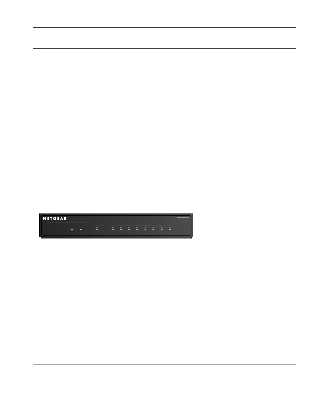
The Firewall’s Front Panel
The front panel of the FVL328 (Figure 1-1) contains status LEDs.
MODEL
ProSafe Hi-Speed VPN Firewall
Cable/DSL
PWR TEST
INTERNET LOCAL
100
LNK/ACT
12345678
100
LNK/ACT
FVL328
Figure 1-1: FVL328 Front Panel
You can use some of the LEDs to verify connections. Table 1-1 lists and describes each LED on
the front panel of the firewall.
Introduction 1-5
Page 18
Model FVL328 ProSafe High-Speed VPN Firewall Reference Manual
These LEDs are green when lit, except for the TEST LED, which is amber.
Table 1-1: LED Descriptions
Label Activity Description
POWER On Power is supplied to the firewall.
TEST On
Off
INTERNET
100 On/Blinking The Internet port is operating at 100 Mbps.
LINK/ACT (Activity) On/Blinking The port detected a link with the Internet WAN connection and is
LOCAL
100 On/Blinking The Local port is operating at 100 Mbps.
LINK/ACT
On/Blinking The Local port has detected a link with a LAN connection and is
(Link/Activity)
The system is initializing.
The system is ready and running.
operating at 10 Mbps. Blinking indicates data transmission.
operating at 10 Mbps. Blinking indicates data transmission.
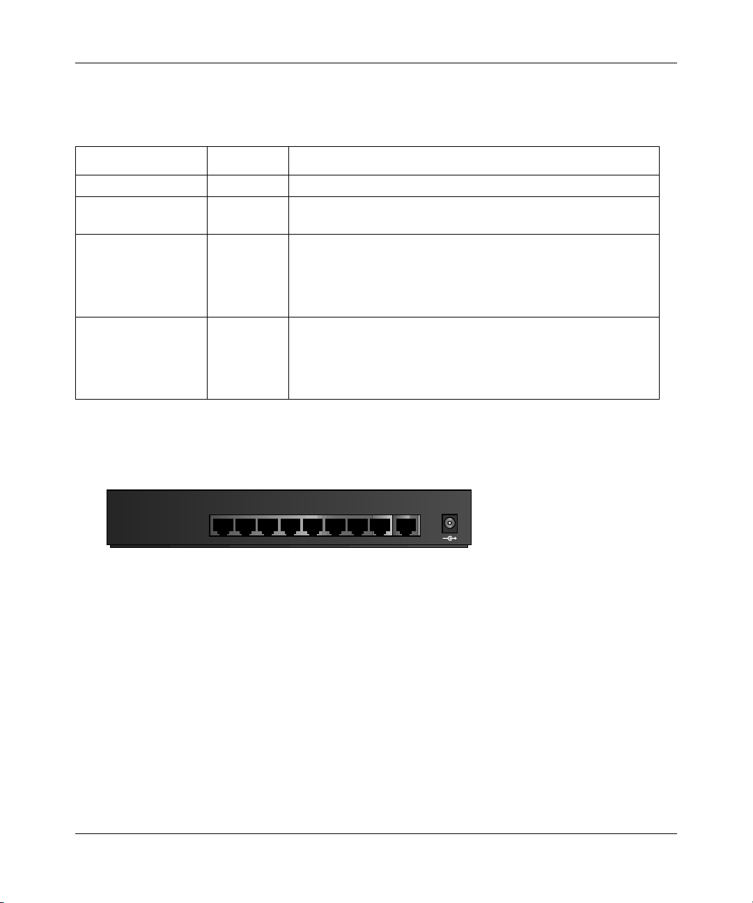
The Firewall’s Rear Panel
The rear panel of the FVL328 (Figure 1-2) contains the connections identified below.
LOCAL
876543221INTERNET
10/100M
12VDC O.5A
Figure 1-2: FVL328 Rear Panel
Viewed from left to right, the rear panel contains the following elements:
• Ground connector
• Factory Default Reset push button
• Eight Local Ethernet RJ-45 ports for connecting the firewall to local computers
• Internet WAN Ethernet RJ-45 port for connecting the firewall to a cable or DSL modem
• AC power adapter input
1-6 Introduction
Page 19

Chapter 2
Connecting the Firewall to the Internet
This chapter describes how to set up the firewall on your Local Area Network (LAN), connect to
the Internet, perform basic configuration of your FVL328 Prosafe High Speed VPN Firewall using
the Setup Wizard, or how to manually configure your Internet connection.
What You Will Need Before You Begin
You need to prepare these three things before you can connect your firewall to the Internet:
1. A computer properly connected to the firewall as explained below.
2. Active Internet service such as that provided by a DSL or Cable modem account.
3. The Internet Service Provider (ISP) configuration information for your DSL or Cable modem
account.
LAN Hardware Requirements
The FVL328 Firewall connects to your LAN via twisted-pair Ethernet cables.
Computer Requirements
To use the FVL328 Firewall on your network, each computer must have an installed Ethernet
Network Interface Card (NIC) and an Ethernet cable. If the computer will connect to your network
at 100 Mbps, you must use a Category 5 (CAT5) cable such as the one provided with your firewall.
Cable or DSL Modem Requirement
The cable modem or DSL modem must provide a standard 10 Mbps 10BASE-T or 100 Mbps
100BASE-T Ethernet interface.
Connecting the Firewall to the Internet 2-1
Page 20

Model FVL328 ProSafe High-Speed VPN Firewall Reference Manual
LAN Configuration Requirements
For the initial connection to the Internet and configuration of your firewall, you will need to
connect a computer to the firewall which is set to automatically get its TCP/IP configuration from
the firewall via DHCP.
Note: Please refer to Appendix C, "Preparing Your Network" for assistance with DHCP
configuration.
Internet Configuration Requirements
Depending on how your ISP or IT group set up your Internet access, you will need one or more of
these configuration parameters to connect your firewall to the Internet:
• Host and Domain Names
• ISP Login Name and Password
• ISP Domain Name Server (DNS) Addresses
• Fixed or Static IP Address
Where Do I Get the Internet Configuration Parameters?
There are several ways you can gather the required Internet connection information.
• Your ISP should have provided you with all the information needed to connect to the Internet.
If you cannot locate this information, you can ask your ISP to provide it or you can try one of
the options below.
• If you have a computer already connected using the active Internet access account, you can
gather the configuration information from that computer.
• For Windows 95/98/Me, open the Network control panel, select the TCP/IP entry for the
Ethernet adapter, and click Properties.
• For Windows 2000/XP, open the Local Area Network Connection, select the TCP/IP entry
for the Ethernet adapter, and click Properties.
• For Macintosh computers, open the TCP/IP or Network control panel.
• You may also refer to the FVL328 Resource CD for the NETGEAR Router ISP Guide which
provides Internet connection information for many ISPs.
Once you locate your Internet configuration parameters, you may want to record them on the page
below according to the instructions in
page 2-3.
2-2 Connecting the Firewall to the Internet
“Recording Your Internet Connection Information” on
Page 21

Model FVL328 ProSafe High-Speed VPN Firewall Reference Manual
Procedure 2-1: Recording Your Internet Connection Information
1. Print this page. Fill in the configuration parameters from your Internet Service Provider (ISP).
ISP Login Name: The login name and password are case sensitive and must be entered exactly as
given by your ISP. Some ISPs use your full e-mail address as the login name. The Service Name is
not required by all ISPs. If you connect using a login name and password, then fill in the
following:
Login Name: ______________________________ Password: ____________________________
Service Name: _____________________________
Fixed or Static IP Address: If you have a static IP address, record the following information. For
example, 169.254.141.148 could be a valid IP address.
Fixed or Static Internet IP Address: ______ . ______ . ______ . ______
Subnet Mask: ______ . ______ . ______ . ______
Gateway IP Address: ______ . ______ . ______ . ______
ISP DNS Server Addresses: If you were given DNS server addresses, fill in the following:
Primary DNS Server IP Address: ______ . ______ . ______ . ______
Secondary DNS Server IP Address: ______ . ______ . ______ . ______
Host and Domain Names: Some ISPs use a specific host or domain name like CCA7324-A or
home. If you haven’t been given host or domain names, you can use the following examples as a
guide:
• If your main e-mail account with your ISP is aaa@yyy.com, then use aaa as your host name.
Your ISP might call this your account, user, host, computer, or system name.
• If your ISP’s mail server is mail.xxx.yyy.com, then use xxx.yyy.com as the domain name.
ISP Host Name: _________________________ ISP Domain Name: _______________________
Connecting the Firewall to the Internet 2-3
Page 22

Model FVL328 ProSafe High-Speed VPN Firewall Reference Manual
Connecting the FVL328 Firewall to Your LAN
This section provides instructions for connecting the FVL328 Prosafe High Speed VPN Firewall
to your
Note: The Resource CD included with your firewall contains an animated Installation Assistant to
help you through this procedure.
Procedure 2-2: Connecting the Firewall to Your LAN
There are three steps to connecting your firewall:
• Connect the firewall to your network.
• Log in to the firewall.
• Connect to the Internet.
Follow the steps below to connect your firewall to your network. You can also refer to the
Resource CD included with your firewall which contains an animated Installation Assistant to help
you through this procedure.
Local Area Network (LAN).
1. Connect the firewall
a. Turn off your computer and cable or DSL modem.
2-4 Connecting the Firewall to the Internet
Page 23
Model FVL328 ProSafe High-Speed VPN Firewall Reference Manual
b. Disconnect the Ethernet cable (A) from your computer which connects to your cable or
DSL modem.
A
DSL modem
Figure 2-1: Disconnect the cable or DSL modem
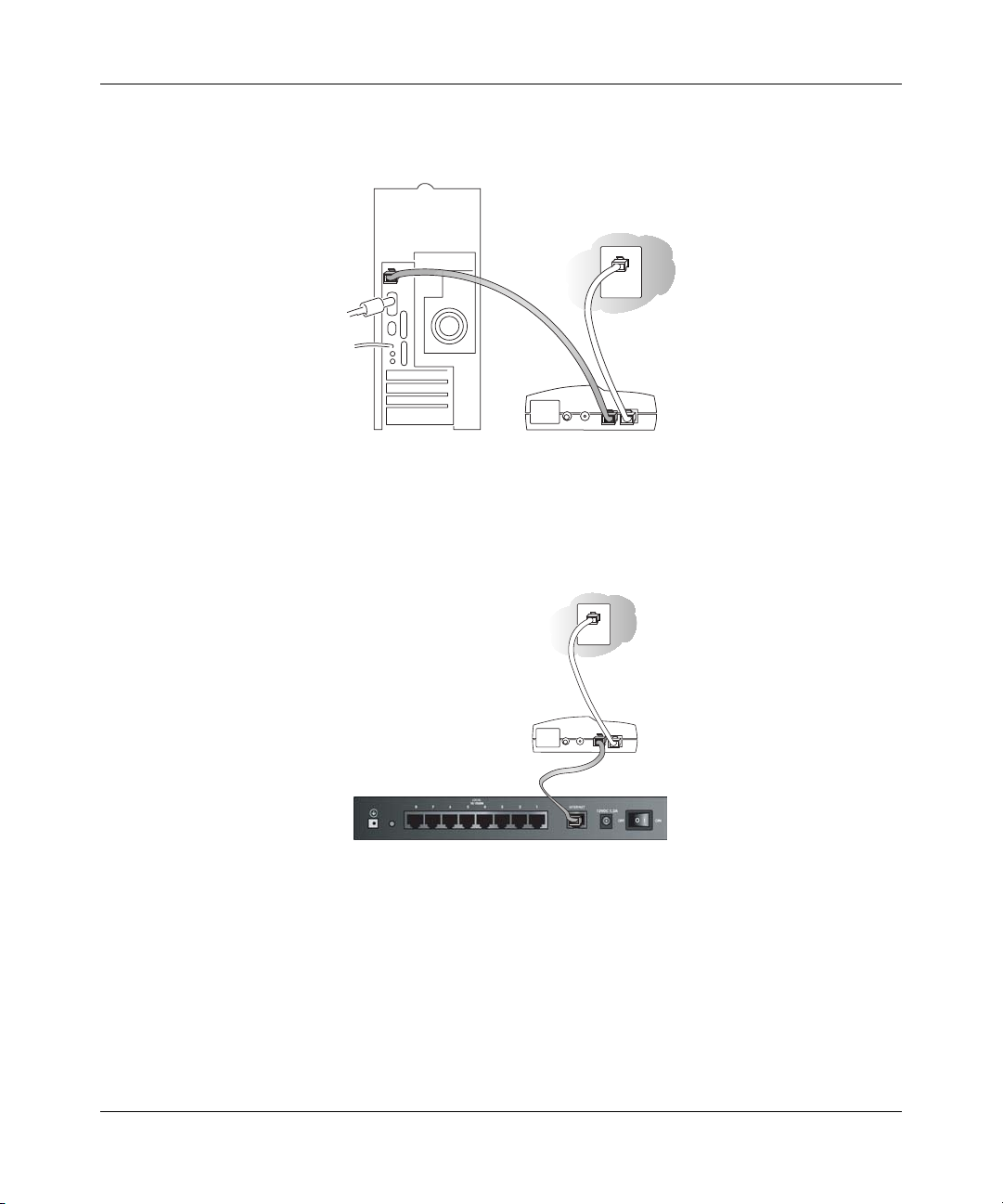
c. Connect the Ethernet cable (A) from your Cable or DSL modem to the FVL328’s Internet
port.
Cable or
DSL modem
A
Figure 2-2: Connect the cable or DSL modem to the firewall
Connecting the Firewall to the Internet 2-5
Page 24
Model FVL328 ProSafe High-Speed VPN Firewall Reference Manual
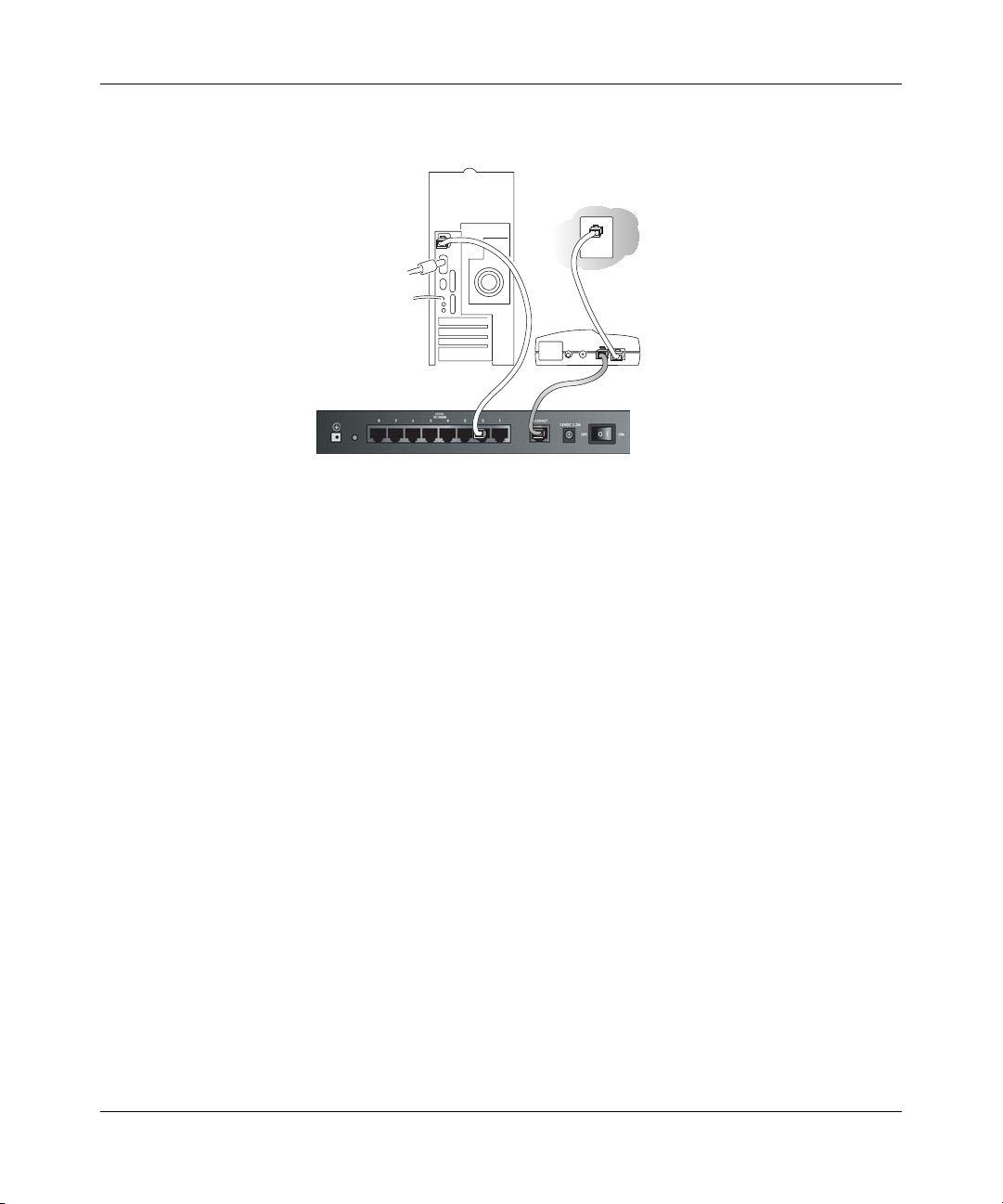
d. Connect the Ethernet cable (B) which came with the firewall from a Local port on the
router to your computer.
Cable or
DSL modem
B
Figure 2-3: Connect the computers on your network to the firewall
Note: The FVL328 Firewall incorporates Auto UplinkTM technology. Each Ethernet port will
automatically sense whether the cable plugged into the port should have a 'normal' connection
(e.g. connecting to a PC) or an 'uplink' connection (e.g. connecting to a switch or hub). That
port will then configure itself to the correct configuration. This feature also eliminates the need
to worry about crossover cables, as Auto Uplink will accommodate either type of cable to
make the right connection.
A
e. Turn on the cable or DSL modem and wait about 30 seconds for the lights to stop blinking.
2. Log in to the firewall
Note: To connect to the firewall, your computer needs to be configured to obtain an IP address
automatically via DHCP. Please refer to
instructions on how to do this.
a. Turn on the firewall and wait for the TEST light to stop blinking.
b. Now, turn on your computer.
Note: If you usually run software to log in to your Internet connection, do not run that
software.
2-6 Connecting the Firewall to the Internet
Appendix C, "Preparing Your Network" for
Page 25
Model FVL328 ProSafe High-Speed VPN Firewall Reference Manual
Now that the cable or DSL modem, firewall, and the computer are turned on, verify the
following:
• When power on the firewall was first turned on, the PWR light went on, the TEST light
turned on within a few seconds, and then went off after approximately 10 seconds.
• The firewall’s LOCAL LINK/ACT lights are lit for any computers that are connected to it.
• The firewall’s INTERNET LINK light is lit, indicating a link has been established to the
cable or DSL modem.
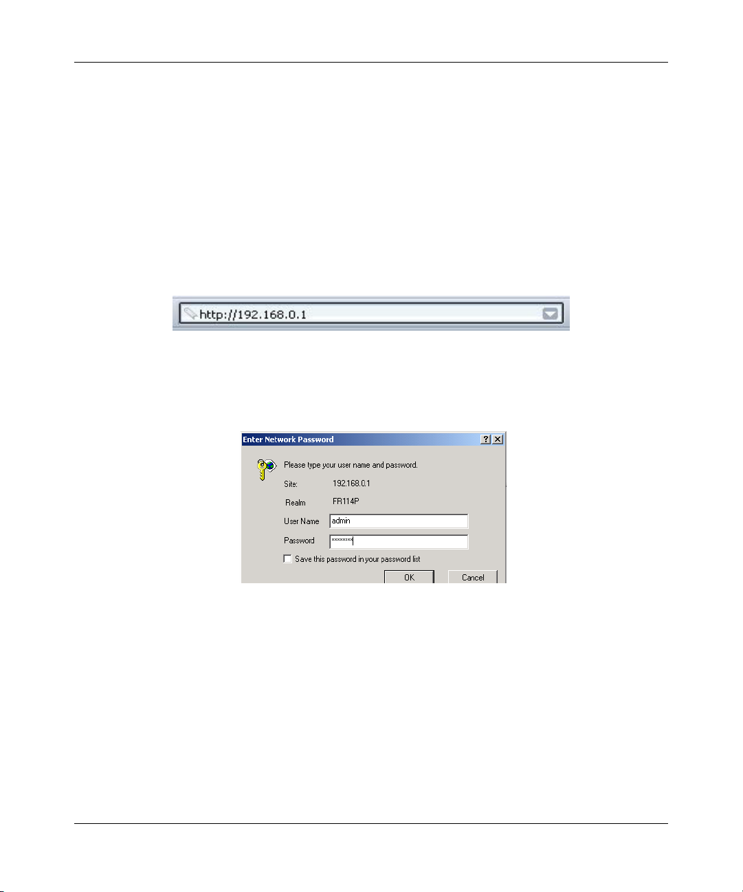
c. Next, use a browser like Internet Explorer or Netscape to log in to the firewall at its default
address of http://192.168.0.1.
Figure 2-4: Log in to the firewall
A login window opens as shown in Figure 2-5 below:
Figure 2-5: Login window
d. For security reasons, the firewall has its own user name and password. When prompted,
admin for the firewall User Name and password for the firewall Password, both in
enter
lower case letters. This default password should be changed later, see,
“Protecting Access
to Your FVL328 Firewall“ on page 3-1.
Note: The user name and password are not the same as any user name or password you
may use to log in to your Internet connection.
Connecting the Firewall to the Internet 2-7
Page 26
Model FVL328 ProSafe High-Speed VPN Firewall Reference Manual
3. Connect to the Internet
Figure 2-6: Setup Wizard
a. You are now connected to the firewall. If you do not see the menu above, click the Setup
Wizard link on the upper left of the main menu. Click the Yes button in the Setup Wizard.
b. Please click Next to follow the steps in the Setup Wizard to input the configuration
parameters from your ISP to connect to the Internet.
Note: If you were unable to connect to the firewall, please refer to “Basic Functions” on page 7-1.
Connecting the FVL328 Firewall to the Internet
The firewall is now properly attached to your network. You are now ready to configure your
firewall to connect to the Internet. There are two ways you can configure your firewall to connect
to the Internet:
• Let the FVL328 auto-detect the type of Internet connection you have and configure it.
• Manually choose which type of Internet connection you have and configure it.
These options are described below. In either case, unless your ISP automatically assigns your
configuration automatically via DHCP, you will need the configuration parameters from your ISP
you recorded in “Recording Your Internet Connection Information” on page 2-3.
2-8 Connecting the Firewall to the Internet
Page 27
Model FVL328 ProSafe High-Speed VPN Firewall Reference Manual
Procedure 2-3: Auto-Detecting Your Internet Connection Type
The Web Configuration Manager built in to the firewall contains a Setup Wizard that can
automatically determine your network connection type.
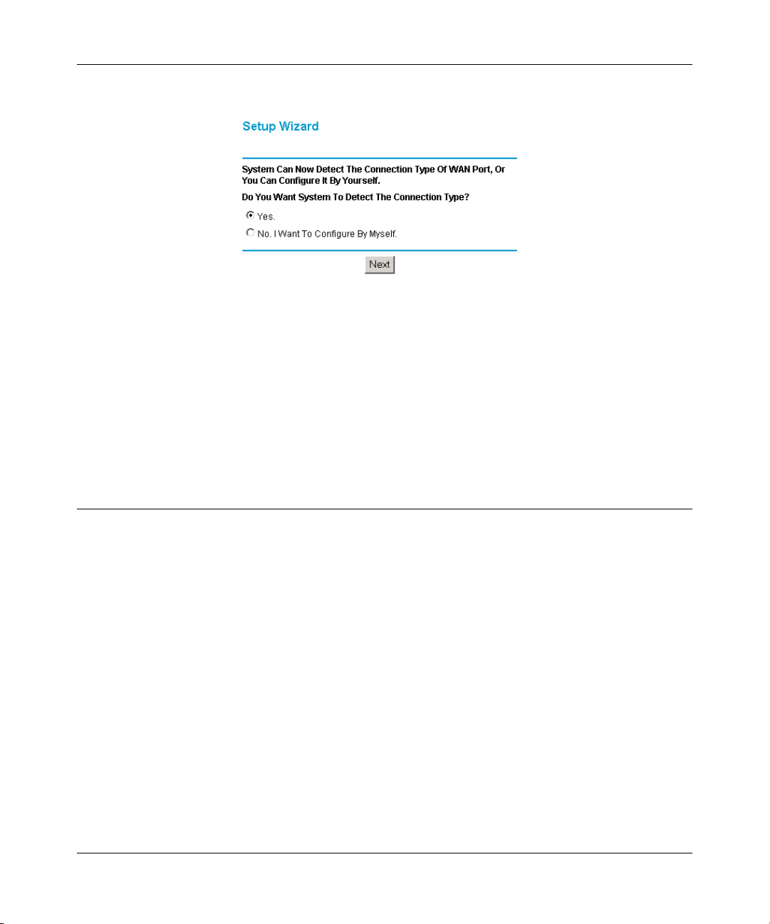
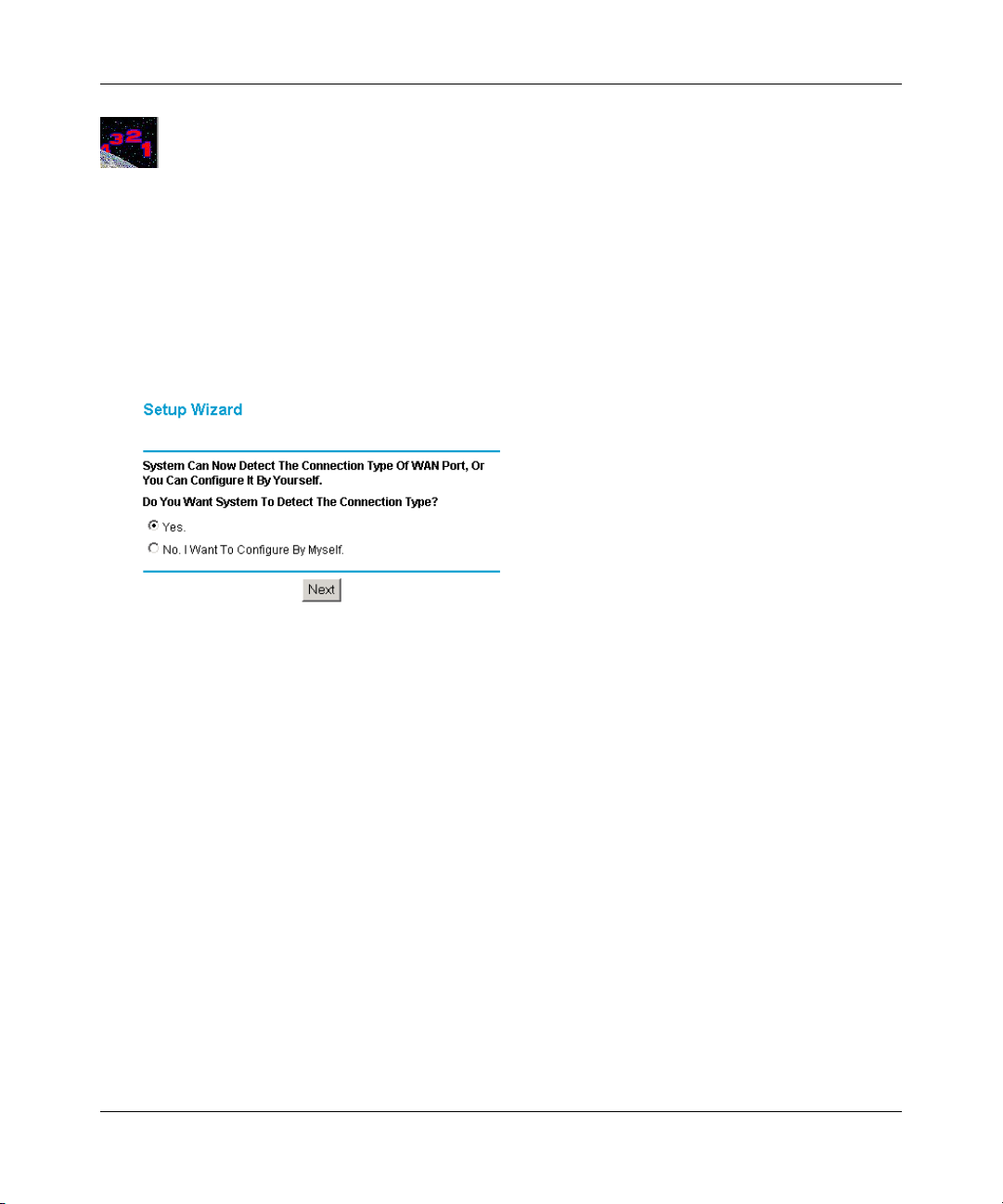
1. If your firewall has not yet been configured, the Setup Wizard shown in Figure 2-7 should
launch automatically.
When the Wizard launches, select Yes in the menu below to allow the firewall to automatically
determine your connection.
Figure 2-7: Built-in Web-based Configuration Manager Setup Wizard
Note: If, instead of the Setup Wizard menu, the main menu of the firewall’s Configuration
Manager as shown in
Figure 2-11 appears, click the Setup Wizard link in the upper left to
bring up this menu.
2. Click Next.
The Setup Wizard will now check for the following connection types:
• Dynamic IP assignment
• A login protocol such as PPPoE
• Fixed IP address assignment
Next, the Setup Wizard will report which connection type it has discovered, and then display
the appropriate configuration menu. If the Setup Wizard finds no connection, you will be
prompted to check the physical connection between your firewall and the cable or DSL
modem. When the connection is properly made, the firewall’s Internet LED should be on.
Connecting the Firewall to the Internet 2-9
Page 28
Model FVL328 ProSafe High-Speed VPN Firewall Reference Manual
The procedures for filling in the configuration menu for each type of connection follow below.
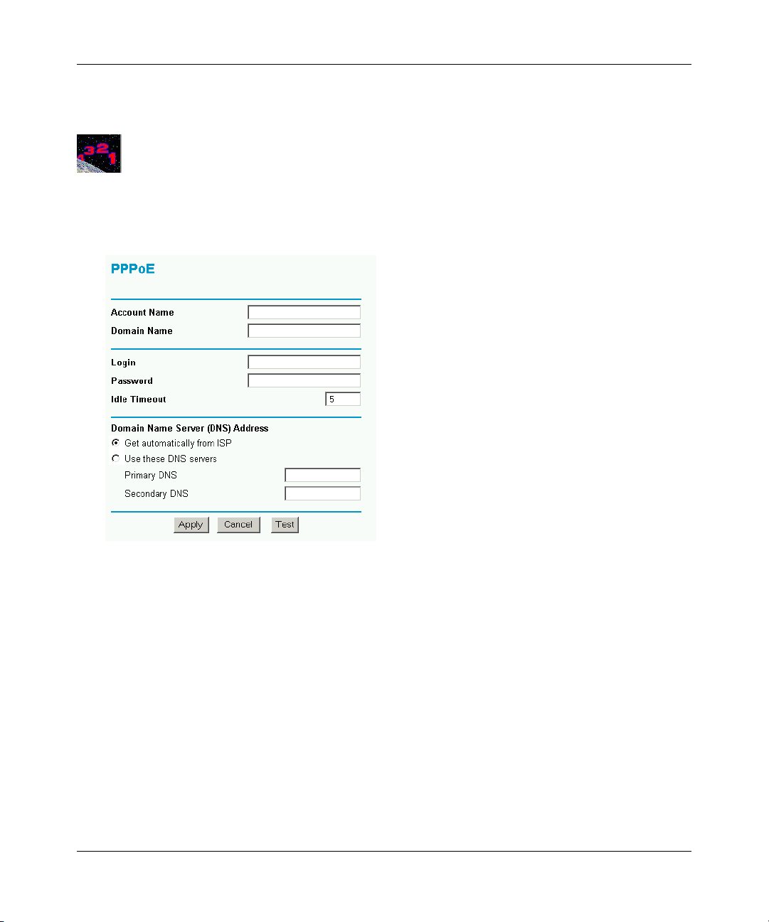
Procedure 2-4: Wizard-Detected Login Account Setup
If the Setup Wizard determines that your Internet service account uses a login protocol such as
PPP over Ethernet (PPPoE), you will be directed to a menu like the PPPoE menu in
Figure 2-8:
Figure 2-8: Setup Wizard menu for PPPoE login accounts
1. Enter your Account Name (may also be called Host Name) and Domain Name. These
parameters may be necessary to access your ISP’s services such as mail or news servers. If you
leave the Domain Name field blank, the firewall will attempt to learn the domain
automatically from the ISP. If this is not successful, you may need to enter it manually.
2. Enter the PPPoE login user name and password provided by your ISP. These fields are case
sensitive. If you wish to change the login timeout, enter a new value in minutes.
Note: You will no longer need to launch the ISP’s login program on your PC in order to access
the Internet. When you start an Internet application, your firewall will automatically log you
in.
2-10 Connecting the Firewall to the Internet
Page 29
Model FVL328 ProSafe High-Speed VPN Firewall Reference Manual
3. Domain Name Server (DNS) Address: If you know that your ISP does not automatically
transmit DNS addresses to the firewall during login, select “Use these DNS servers” and enter
the IP address of your ISP’s Primary DNS Server. If a Secondary DNS Server address is
available, enter it also.
If you enter an address here, after you finish configuring the firewall, reboot your PCs so that
the settings take effect.
4. Click on Apply to save your settings.
5. Click on the Test button to test your Internet connection. If the NETGEAR website does not
appear within one minute, refer to
Chapter 7, Troubleshooting.
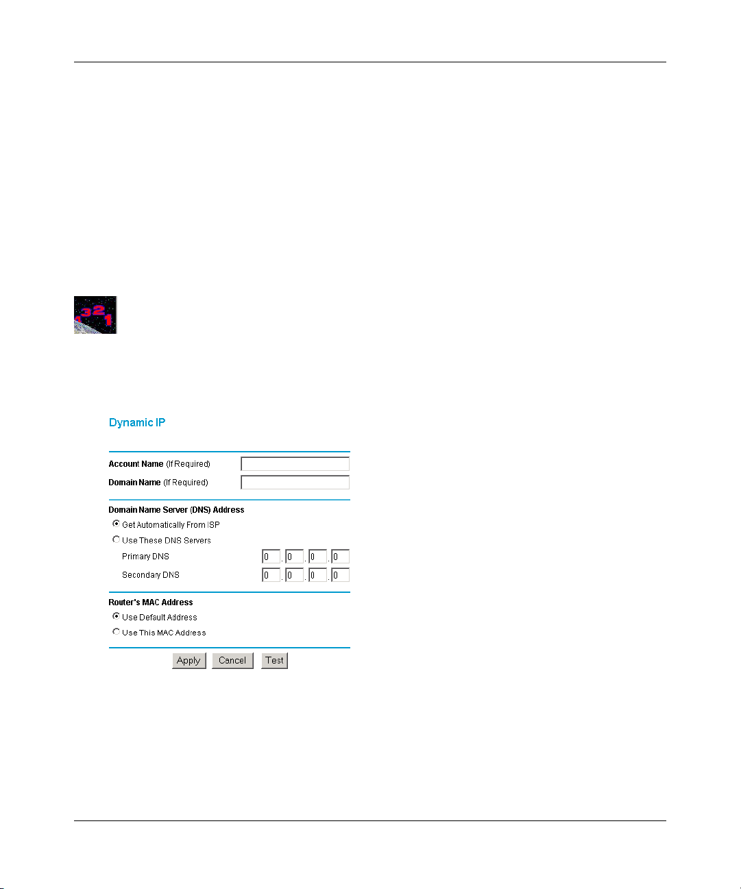
Procedure 2-5: Wizard-Detected Dynamic IP Account Setup
If the Setup Wizard determines that your Internet service account uses Dynamic IP assignment,
you will be directed to the menu shown in
Figure 2-9 below:
Figure 2-9: Setup Wizard menu for Dynamic IP address
1. Enter your Account Name (may also be called Host Name) and Domain Name. These
parameters may be necessary to access your ISP’s services such as mail or news servers. If you
leave the Domain Name field blank, the firewall will attempt to learn the domain
automatically from the ISP. If this is not successful, you may need to enter it manually.
Connecting the Firewall to the Internet 2-11
Page 30

Model FVL328 ProSafe High-Speed VPN Firewall Reference Manual
2. If you know that your ISP does not automatically transmit DNS addresses to the firewall
during login, select “Use these DNS servers” and enter the IP address of your ISP’s Primary
DNS Server. If a Secondary DNS Server address is available, enter it also.
A DNS server is a host on the Internet that translates Internet names (such as
www.netgear.com) to numeric IP addresses. Typically your ISP transfers the IP address of one
or two DNS servers to your firewall during login. If the ISP does not transfer an address, you
must obtain it from the ISP and enter it manually here. If you enter an address here, you should
reboot your PCs after configuring the firewall.
3. The Router’s MAC Address is the Ethernet MAC address that will be used by the firewall on
the Internet port.
If your ISP allows access from only one specific computer’s Ethernet MAC address, select
“Use this MAC address.” The firewall will then capture and use the MAC address of the
computer that you are now using. You must be using the one computer that is allowed by the
ISP. Otherwise, you can type in a MAC address.
Note: Some ISPs will register the Ethernet MAC address of the network interface card in your
PC when your account is first opened. They will then only accept traffic from the MAC
address of that PC. This feature allows your firewall to masquerade as that PC by using its
MAC address.
4. Click on Apply to save your settings.
5. Click on the Test button to test your Internet connection. If the NETGEAR website does not
appear within one minute, refer to
2-12 Connecting the Firewall to the Internet
Chapter 7, Troubleshooting.
Page 31

Model FVL328 ProSafe High-Speed VPN Firewall Reference Manual
Procedure 2-6: Wizard-Detected Fixed IP (Static) Account Setup
If the Setup Wizard determines that your Internet service account uses Fixed IP assignment, you
will be directed to the menu shown in
Figure 2-10: Setup Wizard menu for Fixed IP address
Figure 2-10 below:
1. Enter your assigned IP Address, Subnet Mask, and the IP Address of your ISP’s gateway
router. This information should have been provided to you by your ISP. You will need the
configuration parameters from your ISP you recorded in “Recording Your Internet Connection
Information” on page 2-3.
2. Enter the IP address of your ISP’s Primary DNS Server. If a Secondary DNS Server address is
available, enter it also.
DNS servers are required to perform the function of translating an Internet name such as
www.netgear.com to a numeric IP address. For a fixed IP address configuration, you must
obtain DNS server addresses from your ISP and enter them manually here. You should reboot
your PCs after configuring the firewall for these settings to take effect.
3. Click on Apply to save the settings.
4. Click on the Test button to test your Internet connection. If the NETGEAR website does not
appear within one minute, refer to
Connecting the Firewall to the Internet 2-13
Chapter 7, Troubleshooting.
Page 32

Model FVL328 ProSafe High-Speed VPN Firewall Reference Manual
Testing Your Internet Connection
After completing the Internet connection configuration, your can test your Internet connection.
Log in to the firewall, then, from the Setup Basic Settings link, click on the Test button. If the
NETGEAR website does not appear within one minute, refer to
Your firewall is now configured to provide Internet access for your network. Your firewall
automatically connects to the Internet when one of your computers requires access. It is not
necessary to run a dialer or login application such as Dial-Up Networking or Enternet to connect,
log in, or disconnect. These functions are performed by the firewall as needed.
To access the Internet from any computer connected to your firewall, launch a browser such as
Microsoft Internet Explorer or Netscape Navigator. You should see the firewall’s Internet LED
blink, indicating communication to the ISP. The browser should begin to display a Web page.
The following chapters describe how to configure the advanced features of your firewall, and how
to troubleshoot problems that may occur.
Chapter 7, Troubleshooting.
2-14 Connecting the Firewall to the Internet
Page 33

Model FVL328 ProSafe High-Speed VPN Firewall Reference Manual
Manually Configuring Your Internet Connection
You can manually configure your firewall using the menu below, or you can allow the Setup
Wizard to determine your configuration as described in the previous section.
ISP Does Not Require Login
ISP Does Not Require Login
Figure 2-11: Browser-based configuration Basic Settings menu
Connecting the Firewall to the Internet 2-15
Page 34

Model FVL328 ProSafe High-Speed VPN Firewall Reference Manual
Procedure 2-7: Manual Configuration
You can manually configure the firewall in the Basic Settings menu shown in Figure 2-11 using
these steps:
1. Answer the question, “Does Your Internet Connection Require a Login?”
• Select Yes if you normally must launch a login program such as Enternet or WinPOET in
order to access the Internet.
Note: If you are a Telstra BigPond cable modem customer, or if you are in an area such as
Austria that uses PPTP, login is required. If so, select BigPond or PPTP from the Internet
Service Type drop down box.
• Select No if you do not log in to establish your Internet connection.
2. If you selected Yes, follow the instructions below.
If your Internet connection does not require a login, skip to step 3.
a. Enter your Account Name (may also be called Host Name) and Domain Name.
These parameters may be necessary to access your ISP’s services such as mail or news
servers. These fields are case sensitive.
b. If you wish to change the login timeout, enter a new value in minutes. This determines
how long the firewall keeps the Internet connection active after there is no Internet activity
from the LAN. Entering an Idle Timeout value of zero means never log out.
c. Domain Name Server (DNS) Address:
If you know that your ISP does not automatically transmit DNS addresses to the firewall
during login, select “Use these DNS servers” and enter the IP address of your ISP’s
Primary DNS Server. If a Secondary DNS Server address is available, enter it also
3. If you selected No, follow the instructions below.
a. Enter your Account Name (may also be called Host Name) and Domain Name.
These parameters may be necessary to access your ISP’s services such as mail or news
servers. The Account Name and Domain Name are not always required.
b. Internet IP Address (also commonly called the WAN IP address):
If your ISP has assigned you a permanent, fixed (static) IP address for your PC, select
“Use static IP address.” Enter the IP address that your ISP assigned. Also enter the
netmask and the Gateway IP address. The Gateway is the ISP’s router to which your
firewall will connect.
2-16 Connecting the Firewall to the Internet
Page 35

Model FVL328 ProSafe High-Speed VPN Firewall Reference Manual
c. Domain Name Server (DNS) Address:
If you know that your ISP does not automatically transmit DNS addresses to the firewall
during login, select “Use these DNS servers” and enter the IP address of your ISP’s
Primary DNS Server. If a Secondary DNS Server address is available, enter it also.
A DNS server is a host on the Internet that translates Internet names (such as
www.netgear.com) to numeric IP addresses. Typically your ISP transfers the IP address of
one or two DNS servers to your firewall during login. If the ISP does not transfer an
address, you must obtain it from the ISP and enter it manually here. If you enter an address
here, you should reboot your PCs after configuring the firewall.
d. Router’s MAC Address:
This section determines the Ethernet MAC address that will be used by the firewall on the
Internet port. Some ISPs will register the Ethernet MAC address of the network interface
card in your PC when your account is first opened. They will then only accept traffic from
the MAC address of that PC. This feature allows your firewall to masquerade as that PC
by “cloning” its MAC address.
To change the MAC address, select “Use this Computer’s MAC address.” The firewall
will then capture and use the MAC address of the PC that you are now using. You must be
using the one PC that is allowed by the ISP. Or, select “Use this MAC address” and enter
it.
4. Click Apply to save your settings.
5. Click on the Test button to test your Internet connection.
If the NETGEAR website does not appear within one minute, refer to Chapter 6,
Troubleshooting.Select whether your Internet connection requires a login.
Connecting the Firewall to the Internet 2-17
Page 36

Model FVL328 ProSafe High-Speed VPN Firewall Reference Manual
2-18 Connecting the Firewall to the Internet
Page 37

Chapter 3
Protecting Your Network
This chapter describes how to use the basic firewall features of the FVL328 Prosafe High Speed
VPN Firewall to protect your network.
Protecting Access to Your FVL328 Firewall
For security reasons, the firewall has its own user name and password. Also, after a period of
inactivity for a set length of time, the administrator login will automatically disconnect. When
prompted, enter
can use procedures below to change the firewall's password and the amount of time for the
administrator’s login timeout.
admin for the firewall User Name and password for the firewall Password. You
Note: The user name and password are not the same as any user name or password your may use
to log in to your Internet connection.
NETGEAR recommends that you change this password to a more secure password. The ideal
password should contain no dictionary words from any language, and should be a mixture of both
upper and lower case letters, numbers, and symbols. Your password can be up to 30 characters.
Protecting Your Network 3-1
Page 38
Model FVL328 ProSafe High-Speed VPN Firewall Reference Manual
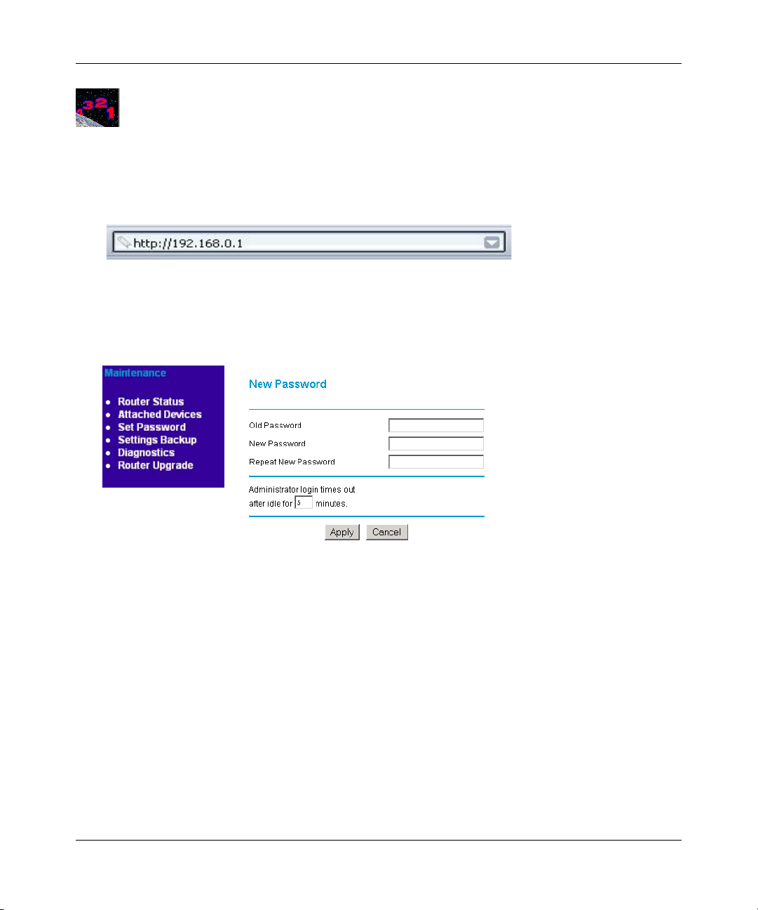
Procedure 3-1: Changing the Built-In Password
1. Log in to the firewall at its default LAN address of http://192.168.0.1 with its default User
Name of
address you have chosen for the firewall.
Figure 3-1: Log in to the firewall
2. From the Main Menu of the browser interface, under the Maintenance heading, select Set
Password to bring up the menu shown in
admin, default password of password, or using whatever password and LAN
Figure 3-2.
Figure 3-2: Set Password menu
3. To change the password, first enter the old password, then enter the new password twice.
4. Click Apply to save your changes.
Note: After changing the password, you will be required to log in again to continue the
configuration. If you have backed up the firewall settings previously, you should do a new backup
so that the saved settings file includes the new password.
3-2 Protecting Your Network
Page 39

Model FVL328 ProSafe High-Speed VPN Firewall Reference Manual
Procedure 3-1: Changing the Administrator Login Timeout
For security, the administrator’s login to the firewall configuration will timeout after a period of
inactivity. To change the login timeout period:
1. In the Set Password menu, type a number in ‘Administrator login times out’ field. The
suggested default value is 5 minutes.
2. Click Apply to save your changes or click Cancel to keep the current period.
Configuring Basic Firewall Services
Basic firewall services you can configure include access blocking and scheduling of firewall
security. These topics are presented below.
Blocking Keywords, Sites, and Services
The firewall provides a variety of options for blocking Internet based content and
communications services. With its content filtering feature, the FVL328 Firewall prevents
objectionable content from reaching your PCs. The FVL328 allows you to control access to
Internet content by screening for keywords within Web addresses. Key content filtering options
include:
• Blocking access from your LAN to Internet locations that you specify as off-limits.
• Keyword blocking of newsgroup names.
• Outbound services blocking to limit access from your LAN to Internet locations or services
that you specify as off-limits.
• Denial of Service (DoS) protection. Automatically detects and thwarts (DoS) attacks such as
Ping of Death, SYN Flood, LAND Attack and IP Spoofing.
• Blocks unwanted traffic from the Internet to your LAN.
The section below explains how to configure your firewall to perform these functions.
Protecting Your Network 3-3
Page 40

Model FVL328 ProSafe High-Speed VPN Firewall Reference Manual
Procedure 3-2: Blocking Keywords and Sites
The FVL328 Firewall allows you to restrict access to Internet content based on functions such as
Java or Cookies, Web addresses and Web address keywords.
1. Log in to the firewall at its default LAN address of http://192.168.0.1 with its default User
Name of
address you have chosen for the firewall.
2. Click on the Block Sites link of the Security menu.
admin, default password of password, or using whatever password and LAN
Figure 3-3: Block Sites menu
3. To enable keyword blocking, check “Turn keyword blocking on”, enter a keyword or domain
in the Keyword box, click Add Keyword, then click Apply.
Some examples of Keyword blocking follow:
• If the keyword “XXX” is specified, the URL <http://www.badstuff.com/xxx.html> is
blocked, as is the newsgroup alt.pictures.xxx.
3-4 Protecting Your Network
Page 41

Model FVL328 ProSafe High-Speed VPN Firewall Reference Manual
• If the keyword “.com” is specified, only websites with other domain suffixes (such as .edu
or .gov) can be viewed.
• If the keyword “.” is entered, all Internet browsing access will be blocked.
Up to 32 entries are supported in the Keyword list.
4. To delete a keyword or domain, select it from the list, click Delete Keyword, then click Apply.
5. To specify a Trusted User, enter that PC’s IP address in the Trusted User box and click Apply.
You may specify one Trusted User, which is a PC that will be exempt from blocking and
logging. Since the Trusted User will be identified by an IP address, you should configure that
PC with a fixed IP address.
6. Click Apply to save your settings.
Rules
Firewall rules are used to block or allow specific traffic passing through from one side to the other.
Inbound rules (WAN to LAN) restrict access by outsiders to private resources, selectively allowing
only specific outside users to access specific resources. Outbound rules (LAN to WAN) determine
what outside resources local users can have access to.
A firewall has two default rules, one for inbound traffic and one for outbound. The default rules of
the FVL328 are:
• Inbound: Block all access from outside except responses to requests from the LAN side.
• Outbound: Allow all access from the LAN side to the outside.
You may define additional rules that will specify exceptions to the default rules. By adding custom
rules, you can block or allow access based on the service or application, source or destination IP
addresses, and time of day. You can also choose to log traffic that matches or does not match the
rule you have defined.
Protecting Your Network 3-5
Page 42

Model FVL328 ProSafe High-Speed VPN Firewall Reference Manual
To access the Rules configuration of the FVL328, click the Rules link on the main menu, then
click Add for either an Outbound or Inbound Service.
Figure 3-4: Rules menu
• To edit an existing rule, select its button on the left side of the table and click Edit.
• To delete an existing rule, select its button on the left side of the table and click Delete.
• To move an existing rule to a different position in the table, select its button on the left side
of the table and click Move. At the script prompt, enter the number of the desired new
position and click OK.
3-6 Protecting Your Network
Page 43

Model FVL328 ProSafe High-Speed VPN Firewall Reference Manual
Inbound Rules (Port Forwarding)
Because the FVL328 uses Network Address Translation (NAT), your network presents only one IP
address to the Internet, and outside users cannot directly address any of your local computers.
However, by defining an inbound rule you can make a local server (for example, a web server or
game server) visible and available to the Internet. The rule tells the firewall to direct inbound
traffic for a particular service to one local server based on the destination port number. This is also
known as port forwarding.
Note: Some residential broadband ISP accounts do not allow you to run any server
processes (such as a Web or FTP server) from your location. Your ISP may periodically
check for servers and may suspend your account if it discovers any active services at
your location. If you are unsure, refer to the Acceptable Use Policy of your ISP.
Remember that allowing inbound services opens holes in your firewall. Only enable those ports
that are necessary for your network. Following are two application examples of inbound rules:
Inbound Rule Example: A Local Public Web Server
If you host a public web server on your local network, you can define a rule to allow inbound web
(HTTP) requests from any outside IP address to the IP address of your web server at any time of
day. This rule is shown in
Figure 3-5:
Figure 3-5: Rule example: a local public Web server
Protecting Your Network 3-7
Page 44

Model FVL328 ProSafe High-Speed VPN Firewall Reference Manual
The parameters are:
•Service
From this list, select the application or service to be allowed or blocked. The list already
displays many common services, but you are not limited to these choices. Use the Add
Services menu as seen in
not already appear.
• Action
Choose how you would like this type of traffic to be handled. You can block or allow
always, or you can choose to block or allow according to the schedule you have defined in
the Schedule menu.
• Send to LAN Server
Figure 3-4 to add any additional services or applications that do
Enter the IP address of the PC or Server on your LAN which will receive the
inbound traffic covered by this rule.
• WAN Users
These settings determine which packets are covered by the rule, based on their
source (WAN) IP address. Select the desired option:
• Any - All IP addresses are covered by this rule.
• Address range - If this option is selected, you must enter the "Start" and "Finish"
fields.
• Single address - Enter the required address in the "Start" fields.
•Log
You can select whether the traffic will be logged. The choices are:
• Never - No log entries will be made for this service.
• Always - Any traffic for this service type will be logged.
• Match - Traffic of this type which matches the parameters and action will be logged.
• Not match - Traffic of this type which does not match the parameters and action will
be logged.
3-8 Protecting Your Network
Page 45

Model FVL328 ProSafe High-Speed VPN Firewall Reference Manual
Inbound Rule Example: Allowing Videoconferencing from Restricted Addresses
If you want to allow incoming videoconferencing to be initiated from a restricted range of outside
IP addresses, such as from a branch office, you can create an inbound rule. In the example shown
in
Figure 3-6, CU-SeeMe connections are allowed only from a specified range of external IP
addresses. In this case, we have also specified logging of any incoming CU-SeeMe requests that
do not match the allowed parameters.
Figure 3-6: Rule example: Videoconferencing from Restricted Addresses
Considerations for Inbound Rules
• If your external IP address is assigned dynamically by your ISP, the IP address may change
periodically as the DHCP lease expires. Consider using the Dynamic DNS feature in the
Advanced menus so that external users can always find your network.
• If the IP address of the local server PC is assigned by DHCP, it may change when the PC is
rebooted. To avoid this, use the Reserved IP address feature in the LAN IP menu to keep the
PC’s IP address constant.
• Local PCs must access the local server using the PCs’ local LAN address (192.168.0.11 in the
example in
Figure 3-6 above). Attempts by local PCs to access the server using the external
WAN IP address will fail.
Protecting Your Network 3-9
Page 46

Model FVL328 ProSafe High-Speed VPN Firewall Reference Manual
Outbound Rules (Service Blocking)
The FVL328 allows you to block the use of certain Internet services by PCs on your network. This
is called service blocking or port filtering. You can define an outbound rule to block Internet
access from a local PC based on:
• IP address of the local PC (source address)
• IP address of the Internet site being contacted (destination address)
•Time of day
• Type of service being requested (service port number)
Following is an application example of outbound rules:
Outbound Rule Example: Blocking Instant Messenger
If you want to block Instant Messenger usage by employees during working hours, you can create
an outbound rule to block that application from any internal IP address to any external address,
according to the schedule that you have created in the Schedule menu. You can also have the
firewall log any attempt to use Instant Messenger during that blocked period.
Figure 3-7: Rule example: blocking instant messenger
3-10 Protecting Your Network
Page 47

The parameters are:
•Service
From this list, select the application or service to be allowed or blocked. The list already
displays many common services, but you are not limited to these choices. Use the Add
Services menu as seen in
not already appear.
• Action
Choose how you would like this type of traffic to be handled. You can block or allow
always, or you can choose to block or allow according to the schedule you have defined in
the Schedule menu.
• LAN Users
These settings determine which packets are covered by the rule, based on their
source LAN IP address. Select the desired option:
• Any: All IP addresses are covered by this rule.
• Address range: If this option is selected, you must enter the "Start" and "Finish" fields.
• Single address: Enter the required address in the "Start" fields.
Model FVL328 ProSafe High-Speed VPN Firewall Reference Manual
Figure 3-4 to add any additional services or applications that do
• WAN Users
These settings determine which packets are covered by the rule, based on their
destination WAN IP address. Select the desired option:
• Any - All IP addresses are covered by this rule.
• Address range - If this option is selected, you must enter the "Start" and "Finish"
fields.
• Single address - Enter the required address in the "Start" fields.
•Log
You can select whether the traffic will be logged. The choices are:
• Never - No log entries will be made for this service.
• Always - Any traffic for this service type will be logged.
• Match - Traffic of this type which matches the parameters and action will be logged.
• Not match - Traffic of this type which does not match the parameters and action will
be logged.
Protecting Your Network 3-11
Page 48

Model FVL328 ProSafe High-Speed VPN Firewall Reference Manual
Order of Precedence for Rules
As you define new rules, they are added to the tables in the Rules menu, as shown in Figure 3-8:
Figure 3-8: Rules table with examples
For any traffic attempting to pass through the firewall, the packet information is subjected to the
rules in the order shown in the Rules Table, beginning at the top and proceeding to the default rules
at the bottom. In some cases, the order of precedence of two or more rules may be important in
determining the disposition of a packet. The Move button allows you to relocate a defined rule to a
new position in the table.
3-12 Protecting Your Network
Page 49

Model FVL328 ProSafe High-Speed VPN Firewall Reference Manual
Services
Services are functions performed by server computers at the request of client computers. For
example, Web servers serve web pages, time servers serve time and date information, and game
hosts serve data about other players’ moves. When a computer on the Internet sends a request for
service to a server computer, the requested service is identified by a service or port number. This
number appears as the destination port number in the transmitted IP packets. For example, a packet
that is sent with destination port number 80 is an HTTP (Web server) request.
The service numbers for many common protocols are defined by the Internet Engineering Task
Force (IETF) and published in RFC1700, “Assigned Numbers.” Service numbers for other
applications are typically chosen from the range 1024 to 65535 by the authors of the application.
For more information on this topic please see
Basics.
Although the FVL328 already holds a list of many service port numbers, you are not limited to
these choices. Use the procedure below to create your own service definitions.
Appendix B, “Networks, Routing, and Firewall
Procedure 3-3: Defining Services
1. Log in to the firewall at its default LAN address of http://192.168.0.1 with its default User
Name of
address you have chosen for the firewall.
2. Click on the Services link of the Security menu to display the menu shown in Figure 3-9:
Figure 3-9: Services menu
• To create a new service, click the Add button.
Protecting Your Network 3-13
admin, default password of password, or using whatever password and LAN
Page 50

Model FVL328 ProSafe High-Speed VPN Firewall Reference Manual
• When there is an existing service, to edit the service, select the it from the list in the table
and click Edit Service.
• To delete an existing Service, select its button on the left side of the table and click Delete.
3. Modify the menu shown below for defining or editing a service.
Figure 3-10: Add Services menu
4. Click Apply to save your changes.
Setting Times and Scheduling Firewall Services
The FVL328 Firewall uses the Network Time Protocol (NTP) to obtain the current time and date
from one of several Network Time Servers on the Internet. In order to localize the time for your
log entries, you must select your Time Zone from the list.
Procedure 3-4: Setting Your Time Zone
In order to localize the time for your log entries, you must specify your Time Zone:
1. Log in to the firewall at its default LAN address of http://192.168.0.1 with its default User
Name of
address you have chosen for the firewall.
3-14 Protecting Your Network
admin, default password of password, or using whatever password and LAN
Page 51

Model FVL328 ProSafe High-Speed VPN Firewall Reference Manual
2. Click on the Schedule link of the Security menu to display the menu shown below.
Figure 3-11: Schedule Services menu
3. Select your Time Zone. This setting will be used for the blocking schedule according to your
local time zone and for time-stamping log entries.
Check the Daylight Savings Time box if your time zone is currently in daylight savings time.
Note: If your region uses Daylight Savings Time, you must manually check Adjust for
Daylight Savings Time on the first day of Daylight Savings Time, and uncheck it at the end.
Enabling Daylight Savings Time will cause one hour to be added to the standard time.
4. Timekeeping has 2 options:
• Synchronize to NTP Server - If enabled, the RTC (Real-Time Clock) is updated regularly
by contacting this server. If you prefer to use a particular NTP server, enter the server’s IP
address. If not enabled, the RTC is never changed.
Protecting Your Network 3-15
Page 52

Model FVL328 ProSafe High-Speed VPN Firewall Reference Manual
• Set Clock - Use this to set a particular Date/Time to the RTC . This is only useful if
“Synchronize to NTP Server” is disabled. Otherwise, your setting will be lost on the next
synchronization
5. Click Apply to save your settings.
.
Procedure 3-5: Scheduling Firewall Services
If you enabled services blocking in the Block Services menu or Port forwarding in the Ports menu,
you can set up a schedule for when blocking occurs or when access is not restricted.
1. Log in to the firewall at its default LAN address of http://192.168.0.1 with its default User
Name of
address you have chosen for the firewall.
2. Click on the Schedule link of the Security menu to display menu shown above in the Schedule
Services menu.
3. To block Internet services based on a schedule, select Every Day or select one or more days. If
you want to limit access completely for the selected days, select All Day. Otherwise, to limit
access during certain times for the selected days, enter Start Blocking and End Blocking times.
admin, default password of password, or using whatever password and LAN
Note: Enter the values as 24-hour time. For example, 10:30 am would be 10 hours and 30
minutes and 10:30 pm would be 22 hours and 30 minutes.
4. Click Apply to save your changes.
3-16 Protecting Your Network
Page 53

Chapter 4
Virtual Private Networking
This chapter describes how to use the virtual private networking (VPN) features of the FVL328
Firewall. VPN tunnels provide secure, encrypted communications between your local network and
a remote network or computer.
Overview of FVL328 Policy-Based VPN Configuration
The FVL328 uses state-of-the-art firewall and security technology to facilitate controlled and
actively monitored VPN connectivity. Since the FVL328 strictly conforms to IETF standards, it is
interoperable with devices from major network equipment vendors.
Telecommuter with
client software
VPN tunnels
encrypt data
FVL328 VPN FirewallFVL328 VPN Firewall
Figure 4-1: Secure access through FVL328 VPN routers
Virtual Private Networking 4-1
Page 54

Model FVL328 ProSafe High-Speed VPN Firewall Reference Manual
Using Policies to Manage VPN Traffic
You create policy definitions to manage VPN traffic on the FVL328. There are two kinds of
policies:
• IKE Policies: Define the authentication scheme and automatically generate the encryption
keys. As an alternative option, to further automate the process, you can create an IKE policy
which uses a trusted certificate authority to provide the authentication while the IKE policy
still handles the encryption.
• VPN Policies: Apply the IKE policy to specific traffic which requires a VPN tunnel. Or, you
can create a VPN policy which does not use an IKE policy but in which you manually enter all
the authentication and key parameters.
Since the VPN policies use the IKE policies, you define the IKE policy first. The FVL328 also
allows you to manually input the authentication scheme and encryption key values. In the case of
manual key management there will not be any IKE policies.
In order to establish secure communication over the Internet with the remote site you need to
configure matching VPN policies on both the local and remote FVL328 Firewalls. The outbound
VPN policy on one end must match to the inbound VPN policy on other end, and vice versa.
When the network traffic enters into the FVL328 from the LAN network interface, if there is no
VPN policy found for a type of network traffic, then that traffic passes through without any
change. However, if the traffic is selected by a VPN policy, then the IPSec authentication and
encryption rules will be applied to it as defined in the VPN policy.
By default, a new VPN policy is added with the least priority, that is, at the end of the VPN policy
table.
Using Automatic Key Management
The most common configuration scenarios will use IKE policies to automatically manage the
authentication and encryption keys. Based on the IKE policy, some parameters for the VPN tunnel
are generated automatically. The IKE protocols perform negotiations between the two VPN
endpoints to automatically generate required parameters.
Some organizations will use an IKE policy with a Certificate Authority (CA) to perform
authentication. Typically, CA authentication is used in large organizations which maintain their
own internal CA server. This requires that each VPN gateway has a certificate from the CA. Using
CAs reduces the amount of data entry required on each VPN endpoint.
4-2 Virtual Private Networking
Page 55

Model FVL328 ProSafe High-Speed VPN Firewall Reference Manual
IKE Policies’ Automatic Key and Authentication Management
Click the IKE Policies link from the VPN section of the main menu, and then click the Add button
of the IKE Policies screen to display the IKE Policy Configuration menu shown in
Figure 4-2.
Figure 4-2: IKE - Policy Configuration Menu
Virtual Private Networking 4-3
Page 56

Model FVL328 ProSafe High-Speed VPN Firewall Reference Manual
The IKE Policy Configuration fields are defined in the following table.
Table 4-1. IKE Policy Configuration Fields
Field Description
General These settings identify this policy and determine its major characteristics.
Policy Name The descriptive name of the IKE policy. Each policy should have a unique
policy name. This name is not supplied to the remote VPN endpoint. It is
only used to help you identify IKE policies.
Direction/Type This setting is used when determining if the IKE policy matches the current
traffic. The drop-down menu includes the following:
• Initiator – Outgoing connections are allowed, but incoming are blocked.
• Responder – Incoming connections are allowed, but outgoing are
blocked.
• Both Directions – Both outgoing and incoming connections are allowed.
• Remote Access – This is to allow only incoming client connections,
where the IP address of the remote client is unknown.
If Remote Access is selected, the “Exchange Mode” MUST be
“Aggressive,” and the ‘Identities’ below (both Local and Remote) MUST
be “Name.” On the matching VPN Policy, the IP address of the remote
VPN endpoint should be set to 0.0.0.0.
Exchange Mode Main Mode or Aggressive Mode. This setting must match the setting used
on the remote VPN endpoint.
• Main Mode is slower but more secure. Also, the “Identity” below must be
established by IP address.
• Aggressive Mode is faster but less secure. The “Identity” below can be by
name (host name, domain name, email address, etc.) instead of by IP
address.
Local
Local Identity
Local IP Address Use this field to identify the local FVL328 by its Internet (WAN) port IP
Name This field lets you identify the local FVL328 by name.
These parameters apply to the Local FVL328 firewall.
address.
4-4 Virtual Private Networking
Page 57

Model FVL328 ProSafe High-Speed VPN Firewall Reference Manual
Table 4-1. IKE Policy Configuration Fields
Field Description
Remote
Remote Identity
Remote IP Address Use this field to identify the remote FVL328 by its Internet (WAN) port IP
Name This field lets you identify the target remote FVL328 by name.
IKE Security Association
(SA) Parameters
Encryption Algorithm Choose the encryption algorithm for this IKE policy:
Authentication Algorithm If you enable Authentication Header (AH), this menu lets you to select from
Authentication Method You may select Pre-Shared Key or RSA Signature.
Pre-Shared Key Specify the key according to the requirements of the Authentication
These parameters apply to the target remote FVL328 firewall.
address.
These parameters determine the properties of the IKE Security
Association.
• DES is the default
• 3DES is more secure
these authentication algorithms:
• MD5 - the default
• SHA-1 - more secure
Algorithm you selected.
• For MD5, the key length should be 16 bytes.
• For SHA-1, the key length should be 20 bytes.
RSA Signature RSA Signature requires a certificate.
Diffie-Hellman (D-H) Group The DH Group setting determines the bit size used in the key exchange.
This must match the value used on the remote gateway.
SA Life Time The amount of time in seconds before the Security Association expires;
over an hour (3600) is common.
Virtual Private Networking 4-5
Page 58
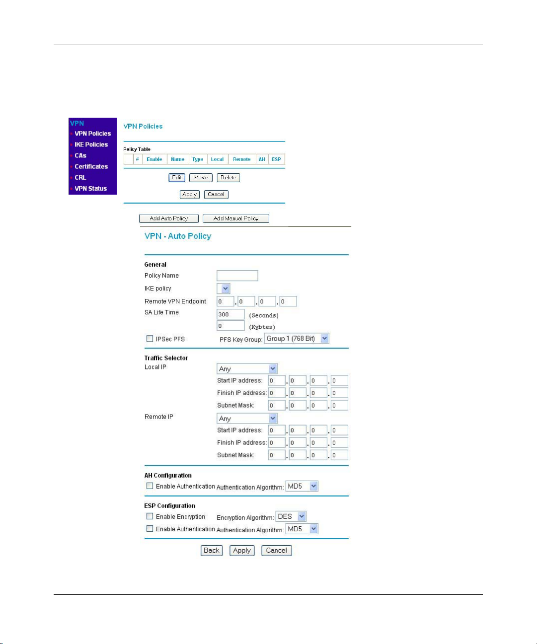
Model FVL328 ProSafe High-Speed VPN Firewall Reference Manual
VPN Policy Configuration for Auto Key Negotiation
An already defined IKE policy is required for VPN - Auto Policy configuration. From the VPN
Policies section of the main menu, you can navigate to the VPN - Auto Policy configuration menu.
Figure 4-3: VPN - Auto Policy Menu
4-6 Virtual Private Networking
Page 59

Model FVL328 ProSafe High-Speed VPN Firewall Reference Manual
The VPN Auto Policy fields are defined in the following table.
Table 4-1. VPN Auto Policy Configuration Fields
Field Description
General
Policy Name The descriptive name of the VPN policy. Each policy should have a unique
IKE Policy The existing IKE policies are presented in a drop-down list.
Remote VPN Endpoint The WAN Internet IP address of the remote VPN firewall or client to which
SA Life Time The duration of the Security Association before it expires.
IPSec PFS
PFS Key Group If PFS is enabled, this setting determines the DH group bit size used in the
These settings identify this policy and determine its major characteristics.
policy name. This name is not supplied to the remote VPN endpoint. It is
only used to help you identify VPN policies.
Note: Create the IKE policy BEFORE creating a VPN - Auto policy.
you wish to connect. The remote VPN endpoint must have this FVL328’s
WAN Internet IP address entered as its “Remote VPN Endpoint.”
• Seconds - the amount of time before the SA expires. Over an hour is
common (3600).
• Kbytes - the amount of traffic before the SA expires.
One of these can be set without setting the other.
If enabled, security is enhanced by ensuring that the key is changed at
regular intervals. Also, even if one key is broken, subsequent keys are no
easier to break. Each key has no relationship to the previous key.
key exchange. This must match the value used on the remote gateway.
Traffic Selector These settings determine if and when a VPN tunnel will be established. If
network traffic meets all criteria, then a VPN tunnel will be created.
Local IP The drop-down menu allows you to configure the source IP address of the
outbound network traffic for which this VPN policy will provide security.
Usually, this address will be from your network address space. The
choices are:
• ANY for all valid IP addresses in the Internet address space
• Single IP Address
• Range of IP Addresses
• Subnet Address
Virtual Private Networking 4-7
Page 60

Model FVL328 ProSafe High-Speed VPN Firewall Reference Manual
Table 4-1. VPN Auto Policy Configuration Fields
Field Description
Remote IP The drop-down menu allows you to configure the destination IP address of
the outbound network traffic for which this VPN policy will provide security.
Usually, this address will be from the remote site's corporate network
address space. The choices are:
• ANY for all valid IP addresses in the Internet address space
• Single IP Address
• Range of IP Addresses
• Subnet Address
Authenticating Header (AH)
Configuration
Enable Authentication Use this checkbox to enable or disable AH for this VPN policy.
Authentication
Algorithm
Encapsulated Security
Payload (ESP) Configuration
Enable Encryption Use this checkbox to enable or disable ESP Encryption.
Encryption
Algorithm
Enable Authentication Use this checkbox to enable or disable ESP transform for this VPN policy.
AH specifies the authentication protocol for the VPN header. These
settings must match the remote VPN endpoint.
If you enable AH, then select the authentication algorithm:
• MD5 - the default
• SHA1 - more secure
ESP provides security for the payload (data) sent through the VPN tunnel.
Generally, you will want to enable both Encryption and Authentication.
Two ESP modes are available:
• Plain ESP encryption
• ESP encryption with authentication
These settings must match the remote VPN endpoint.
If you enable ESP encryption, then select the encryption algorithm:
• DES - the default
• 3DES - more secure
You can select the ESP mode also with this menu.
Two ESP modes are available:
•Plain ESP
• ESP with authentication
Authentication
Algorithm
If you enable AH, then use this menu to select which authentication
algorithm will be employed.
The choices are:
• MD5 - the default
• SHA1 - more secure
4-8 Virtual Private Networking
Page 61

Model FVL328 ProSafe High-Speed VPN Firewall Reference Manual
VPN Policy Configuration for Manual Key Exchange
With Manual Key Management, you will not use an IKE policy. You must manually type in all the
required key information. Click the VPN Policies link from the VPN section of the main menu to
display the menu shown in
Figure 4-4.
Figure 4-4: VPN - Manual Policy Menu
Virtual Private Networking 4-9
Page 62

Model FVL328 ProSafe High-Speed VPN Firewall Reference Manual
The VPN Manual Policy fields are defined in the following table.
Table 4-1. VPN Manual Policy Configuration Fields
Field Description
General
Policy Name The name of the VPN policy. Each policy should have a unique policy
Remote VPN Endpoint The WAN Internet IP address of the remote VPN firewall or client to which
Traffic Selector These settings determine if and when a VPN tunnel will be established. If
Local IP The drop down menu allows you to configure the source IP address of the
Remote IP The drop down menu allows you to configure the destination IP address of
These settings identify this policy and determine its major characteristics.
name. This name is not supplied to the remote VPN Endpoint. It is used to
help you identify VPN policies.
you wish to connect. The remote VPN endpoint must have this FVL328’s
WAN Internet IP address entered as its “Remote VPN Endpoint.”
network traffic meets all criteria, then a VPN tunnel will be created.
outbound network traffic for which this VPN policy will provide security.
Usually, this address will be from your network address space. The
choices are:
• ANY for all valid IP addresses in the Internet address space
• Single IP Address
• Range of IP Addresses
• Subnet Address
the outbound network traffic for which this VPN policy will provide security.
Usually, this address will be from the remote site's corporate network
address space. The choices are:
• ANY for all valid IP addresses in the Internet address space
• Single IP Address
• Range of IP Addresses
• Subnet Address
4-10 Virtual Private Networking
Page 63

Model FVL328 ProSafe High-Speed VPN Firewall Reference Manual
Table 4-1. VPN Manual Policy Configuration Fields
Field Description
Authenticating Header (AH)
Configuration
SPI - Incoming
SPI - Outgoing Enter a Hex value (3 - 8 chars). Any value is acceptable, provided the
Enable Authentication Use this checkbox to enable or disable AH. Authentication is often not
Authentication
Algorithm
Key - In
AH specifies the authentication protocol for the VPN header. These
settings must match the remote VPN endpoint.
Note: The "Incoming" settings here must match the "Outgoing" settings on
the remote VPN endpoint, and the "Outgoing" settings here must match
the "Incoming" settings on the remote VPN endpoint.
Enter a Hex value (3 - 8 chars). Any value is acceptable, provided the
remote VPN endpoint has the same value in its "Outgoing SPI" field.
remote VPN endpoint has the same value in its "Incoming SPI" field.
used. In this case, leave the checkbox unchecked.
If you enable AH, then select the authentication algorithm:
• MD5 - the default
• SHA1 - more secure
Enter the keys in the fields provided. For MD5, the keys should be 16
characters. For SHA-1, the keys should be 20 characters.
Enter the keys.
• For MD5, the keys should be 16 characters.
• For SHA-1, the keys should be 20 characters.
Any value is acceptable, provided the remote VPN endpoint has the same
value in its Authentication Algorithm "Key - Out" field.
Key - Out Enter the keys in the fields provided.
• For MD5, the keys should be 16 characters.
• For SHA-1, the keys should be 20 characters.
Any value is acceptable, provided the remote VPN endpoint has the same
value in its Authentication Algorithm "Key - In" field.
Encapsulated Security
Payload (ESP) Configuration
ESP provides security for the payload (data) sent through the VPN tunnel.
Generally, you will want to enable both encryption and authentication.
when you use ESP. Two ESP modes are available:
• Plain ESP encryption
• ESP encryption with authentication
These settings must match the remote VPN endpoint.
Virtual Private Networking 4-11
Page 64

Model FVL328 ProSafe High-Speed VPN Firewall Reference Manual
Table 4-1. VPN Manual Policy Configuration Fields
Field Description
SPI - Incoming
SPI - Outgoing Enter a Hex value (3 - 8 chars). Any value is acceptable, provided the
Enable Encryption Use this checkbox to enable or disable ESP Encryption.
Encryption
Algorithm
Key - In
Key - Out Enter the key in the fields provided.
Enable Authentication Use this checkbox to enable or disable ESP authentication for this VPN
Authentication
Algorithm
Key - In
Enter a Hex value (3 - 8 chars). Any value is acceptable, provided the
remote VPN endpoint has the same value in its "Outgoing SPI" field.
remote VPN endpoint has the same value in its "Incoming SPI" field.
If you enable ESP Encryption, then select the Encryption Algorithm:
• DES - the default
• 3DES -more secure
Enter the key in the fields provided.
• For DES, the key should be 8 characters.
• For 3DES, the key should be 24 characters.
Any value is acceptable, provided the remote VPN endpoint has the same
value in its Encryption Algorithm "Key - Out" field.
• For DES, the key should be 8 characters.
• For 3DES, the key should be 24 characters.
Any value is acceptable, provided the remote VPN endpoint has the same
value in its Encryption Algorithm "Key - In" field.
policy.
If you enable authentication, then use this menu to select the algorithm:
• MD5 - the default
• SHA1 - more secure
Enter the key.
• For MD5, the key should be 16 characters.
• For SHA-1, the key should be 20 characters.
Any value is acceptable, provided the remote VPN endpoint has the same
value in its Authentication Algorithm "Key - Out" field.
Key - Out Enter the key in the fields provided.
• For MD5, the key should be 16 characters.
• For SHA-1, the key should be 20 characters.
Any value is acceptable, provided the remote VPN endpoint has the same
value in its Authentication Algorithm "Key - In" field.
4-12 Virtual Private Networking
Page 65

Model FVL328 ProSafe High-Speed VPN Firewall Reference Manual
Using Digital Certificates for IKE Auto-Policy Authentication
Digital certificates are strings generated using encryption and authentication schemes which
cannot be duplicated by anyone without access to the different values used in the production of the
string. They are issued by Certification Authorities (CAs) to authenticate a person or a workstation
uniquely. The CAs are authorized to issue these certificates by Policy Certification Authorities
(PCAs), who are in turn certified by the
FVL328 is able to use certificates to authenticate users at the end points during the IKE key
exchange process.
The certificates can be obtained from a certificate server an organization might maintain internally
or from the established public CAs. The certificates are produced by providing the particulars of
the user being identified to the CA. The information provided may include the user's name, e-mail
ID, domain name, etc.
Each CA has its own certificate. The certificates of a CA are added to the FVL328 and can then be
used to form IKE policies for the user. Once a CA certificate is added to the FVL328 and a
certificate is created for a user, the corresponding IKE policy is added to the FVL328. Whenever
the user tries to send traffic through the FVL328, the certificates are used in place of pre-shared
keys during initial key exchange as the authentication and key generation mechanism. Once the
keys are established and the tunnel is set up the connection proceeds according to the VPN policy.
Internet Policy Registration Authority (IPRA). The
Certificate Revocation List (CRL)
Each Certification Authority (CA) maintains a list of the revoked certificates. The list of these
revoked certificates is known as the
Whenever an IKE policy receives the certificate from a peer, it checks for this certificate in the
CRL on the FVL328 obtained from the corresponding CA. If the certificate is not present in the
CRL it means that the certificate is not revoked. IKE can then use this certificate for
authentication. If the certificate is present in the CRL it means that the certificate is revoked, and
the IKE will not authenticate the client.
You must manually update the FVL328 CRL regularly in order for the CA-based authentication
process to remain valid.
Virtual Private Networking 4-13
Certificate Revocation List (CRL).
Page 66

Model FVL328 ProSafe High-Speed VPN Firewall Reference Manual
Walk-Through of Configuration Scenarios on the FVL328
There are a variety of configurations you might implement with the FVL328. The scenarios listed
below illustrate typical configurations you might use in your organization.
In order to help make it easier to set up an IPsec system, the following two scenarios are provided.
These scenarios were developed by the VPN Consortium (http://www.vpnc.org). The goal is to
make it easier to get the systems from different vendors to interoperate. NETGEAR is providing
you with both of these scenarios in the following two formats:
• VPN Consortium Scenarios without Any Product Implementation Details
• VPN Consortium Scenarios Based on the FVL328 User Interface
The purpose of providing these two versions of the same scenarios is to help you determine where
the two vendors use different vocabulary. Seeing the examples presented in these different ways
will reveal how systems from different vendors do the same thing.
Note: NETGEAR will publish additional interoperability scenarios with various gateway
and client software products. Look on the NETGEAR web site at www.netgear.com for
the HTML version of this manual. The scenarios will be published as an additional
section of the on-line version of this reference manual.
4-14 Virtual Private Networking
Page 67

Model FVL328 ProSafe High-Speed VPN Firewall Reference Manual
VPN Consortium Scenario 1: Gateway-to-Gateway with Preshared Secrets
The following is a typical gateway-to-gateway VPN that uses a preshared secret for authentication.
10.5.6.0/24
Gateway A
10.5.6.1
Figure 4-5: VPN Consortium Scenario 1
14.15.16.17 22.23.24.25
Internet
Gateway B
172.23.9.0/24
172.23.9.1
Gateway A connects the internal LAN 10.5.6.0/24 to the Internet. Gateway A's LAN interface has
the address 10.5.6.1, and its WAN (Internet) interface has the address 14.15.16.17.
Gateway B connects the internal LAN 172.23.9.0/24 to the Internet. Gateway B's WAN (Internet)
interface has the address 22.23.24.25. Gateway B's LAN interface address, 172.23.9.1, can be used
for testing IPsec but is not needed for configuring Gateway A.
The IKE Phase 1 parameters used in Scenario 1 are:
•Main mode
• TripleDES
• SHA-1
• MODP group 2 (1024 bits)
• pre-shared secret of "hr5xb84l6aa9r6"
• SA lifetime of 28800 seconds (eight hours) with no kbytes rekeying
The IKE Phase 2 parameters used in Scenario 1 are:
• TripleDES
• SHA-1
• ESP tunnel mode
• MODP group 2 (1024 bits)
• Perfect forward secrecy for rekeying
• SA lifetime of 3600 seconds (one hour) with no kbytes rekeying
• Selectors for all IP protocols, all ports, between 10.5.6.0/24 and 172.23.9.0/24, using IPv4
subnets
Virtual Private Networking 4-15
Page 68

Model FVL328 ProSafe High-Speed VPN Firewall Reference Manual
FVL328 Scenario 1: FVL328 to Gateway B with IKE and VPN Policies
Note: This scenario assumes all ports are open on the FVL328. You can verify this by reviewing
the security settings as seen in the
Use this scenario illustration and configuration screens as a model to build your configuration.
FVL328
Gateway A
LAN IP
Figure 4-6: LAN to LAN VPN access from an FVL328 to an FVL328
1. Log in to the FVL328 labeled Gateway A as in the illustration.
“Rules menu” on page 3-6.
Scenario 1
14.15.16.17 22.23.24.25
WAN IP
WAN IP
Gateway B
172.23.9.1/2410.5.6.1/24
LAN IP
Log in to the firewall at its default LAN address of http://192.168.0.1 with its default user
name of
admin and default password of password, or using whatever Password and LAN
address you have chosen for the firewall.
2. Configure the WAN (Internet) and LAN IP addresses of the FVL328.
a. From the main menu Setup section, click on the Basic Setup link.
WAN IP
ISP Provides
These Addresses
Figure 4-7: FVL328 Internet IP Address menu
4-16 Virtual Private Networking
addresses
Page 69

Model FVL328 ProSafe High-Speed VPN Firewall Reference Manual
b. Configure the WAN Internet Address according to the settings in Figure 4-6 above and
click Apply to save your settings. For more information on configuring the WAN IP
settings in the Basic Setup topics, please see
c. From the main menu Advanced section, click on the LAN IP Setup link.
“Manual Configuration” on page 2-16.
d. Configure the LAN IP address according to the settings in Figure 4-6 above and click
Apply to save your settings. For more information on LAN TCP/IP setup topics, please
“Configuring LAN TCP/IP Setup” on page 6-5.
see
Note: After you click Apply to change the LAN IP address settings, your workstation will
be disconnected from the FVL328. You will have to log on with http://10.5.6.1 which is
now the address you use to connect to the built-in web-based configuration manager of the
FVL328.
Virtual Private Networking 4-17
Page 70

Model FVL328 ProSafe High-Speed VPN Firewall Reference Manual
3. Set up the IKE Policy illustrated below on the FVL328.
a. From the main menu VPN section, click on the IKE Policies link, and then click the Add
button to display the screen below.
Figure 4-8: Scenario 1 IKE Policy
b. Configure the IKE Policy according to the settings in the illustration above and click
Apply to save your settings. For more information on IKE Policy topics, please see
“IKE
Policies’ Automatic Key and Authentication Management” on page 4-3.
4-18 Virtual Private Networking
Page 71

Model FVL328 ProSafe High-Speed VPN Firewall Reference Manual
4. Set up the FVL328 VPN -Auto Policy illustrated below.
a. From the main menu VPN section, click on the VPN Policies link, and then click on the
Add Auto Policy button.
WAN IP
addresses
LAN IP
addresses
Figure 4-9: Scenario 1 VPN - Auto Policy
b. Configure the IKE Policy according to the settings in the illustration above and click
Apply to save your settings. For more information on IKE Policy topics, please see
“IKE
Policies’ Automatic Key and Authentication Management” on page 4-3.
Virtual Private Networking 4-19
Page 72

Model FVL328 ProSafe High-Speed VPN Firewall Reference Manual
5. After applying these changes, you will see a table entry like the one below.
Figure 4-10: VPN Policies table
Now all traffic from the range of LAN IP addresses specified on FVL328 A and FVL328 B
will flow over a secure VPN tunnel.
Procedure 4-1: Checking VPN Connections
You can test connectivity and view VPN status information on the FVL328.
1. To test connectivity between the Gateway A FVL328 LAN and the Gateway B LAN, follow
these steps:
a. Using our example, from a PC attached to the FVL328 on LAN A, on a Windows PC click
the Start button on the taskbar and then click Run.
b. Type ping -t 172.23.9.1, and then click OK.
c. This will cause a continuous ping to be sent to the LAN interface of Gateway B. After
between several seconds and two minutes, the ping response should change from “timed
out” to “reply.”
d. At this point the connection is established.
4-20 Virtual Private Networking
Page 73

Model FVL328 ProSafe High-Speed VPN Firewall Reference Manual
2. To test connectivity between the FVL328 Gateway A and Gateway B WAN ports, follow these
steps:
a. Using our example, log in to the FVL328 on LAN A, go to the main menu Maintenance
section and click the Diagnostics link.
b. To test connectivity to the WAN port of Gateway B, enter 22.23.24.25, and then click
Ping.
c. This will cause a ping to be sent to the WAN interface of Gateway B. After between
several seconds and two minutes, the ping response should change from “timed out” to
“reply.” You may have to run this test several times before you get the “reply” message
back from the target FVL328.
d. At this point the connection is established.
Note: If you want to ping the FVL328 as a test of network connectivity, be sure the FVL328 is
configured to respond to a ping on the Internet WAN port by checking the checkbox seen in
“Rules menu” on page 3-6. However, to preserve a high degree of security, you should turn off
this feature when you are finished with testing.
3. To view the FVL328 event log and status of Security Associations, follow these steps:
a. Go to the FVL328 main menu VPN section and click the VPN Status link.
b. The log screen will display a history of the VPN connections, and the IPSec SA and IKE
SA tables will report the status and data transmission statistics of the VPN tunnels for each
policy.
Virtual Private Networking 4-21
Page 74

Model FVL328 ProSafe High-Speed VPN Firewall Reference Manual
VPN Consortium Scenario 2: Gateway-to-Gateway with Certificates
The following is a typical gateway-to-gateway VPN that uses PKIX certificates for authentication.
The network setup is identical to the one given in scenario 1. The IKE Phase 1 and Phase 2
parameters are identical to the ones given in scenario 1, with the exception that the identification is
done with signatures authenticated by PKIX certificates.
The sequence of steps for using the PKIX certificates include:
1. Generating a new public/private key pair.
2. Creating a certificate request for this gateway; including the fields which must or must not be
included in the certificate.
3. Transmitting that request to a Trusted Root CA.
4. Receiving the certificate back from the Trusted Root CA.
5. Installing the new user certificate.
6. Installing the trusted CA certificate for the Trusted Root CA.
7. Associating the new end entity certificate and the Trusted Root CA certificate with the SA for
Gateway B.
8. Setting up CRL checking.
FVL328 Scenario 2: FVL328 to FVL328 with RSA Certificates
Note: Before completing this configuration scenario, make sure the correct Time Zone is set on the
FVL328. For instructions on this topic, please see,
1. Generate a new public/private key pair.
a. Obtain a certificate from a Certificate Authority (CA)
Note: The procedure for obtaining certificates differs from a CA like Verisign and a CA
such as a Windows 2000 certificate server, which an organization operates for providing
certificates for its members. For example, an administrator of a Windows 2000 certificate
server might provide it to you via e-mail.
b. Save the certificate as a text file called trust.txt.
4-22 Virtual Private Networking
“Setting Your Time Zone” on page 3-14.
Page 75
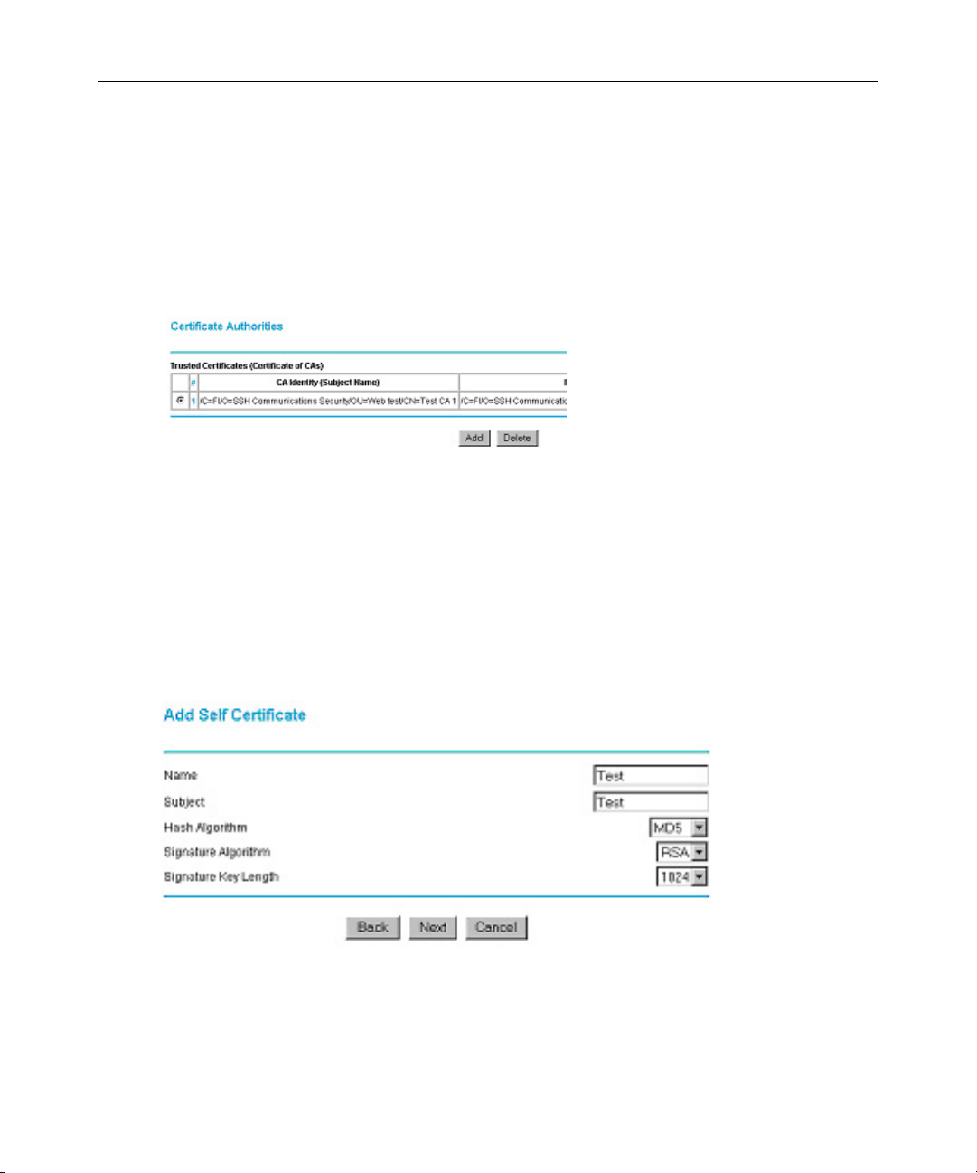
Model FVL328 ProSafe High-Speed VPN Firewall Reference Manual
2. Install the trusted CA certificate for the Trusted Root CA.
a. Log in to the FVL328, and upload the trust.txt certificate file.
b. From the main menu VPN section, click on the CA link.
c. Click Add to add a CA.
d. Click Browse to locate the trust.txt file.
e. Click Upload.
Figure 4-11: VPN Policies table
You will now see a screen such as the one above showing that the Certificate Authority is
now registered with the FVL328.
3. Create a certificate request for the FVL328.
a. From the main menu VPN section, click on the Certificates link and click Add.
b. Fill in the requested fields on the Add Self Certificate screen.
Figure 4-12: Add Self Certificates required fields
Virtual Private Networking 4-23
Page 76

Model FVL328 ProSafe High-Speed VPN Firewall Reference Manual
c. Click Next to continue. The FVL328 generates a Self Certificate Request as shown below.
Figure 4-13: Self Certificate Request data
4. Transmit the Self Certificate Request to the Trusted Root CA.
a. Highlight the text in the Data to Supply to CA area, copy it, and paste it into a text file.
b. Give the certificate request data to the CA. In the case of a Windows 2000 internal CA,
you might simply e-mail it to the CA administrator. The procedures of a CA like Verisign
and a CA such as a Windows 2000 certificate server administrator will differ. Follow the
procedures of your CA.
5. Receive the certificate back from the Trusted Root CA.
Note: In the case of a Windows 2000 internal CA, the CA administrator might simply email it
to back to you. Follow the procedures of your CA. Save the certificate you get back from the
CA as a text file called final.txt.
6. Install the new certificate.
a. From the main menu VPN section, click on the Certificates link and click Add.
b. If you closed the menu from the previous session, fill in the requested fields on the Add
Self Certificate screen exactly as you did earlier.
4-24 Virtual Private Networking
Page 77

Model FVL328 ProSafe High-Speed VPN Firewall Reference Manual
c. Click Next to continue.
Figure 4-14: Certificate Upload
d. Click Browse to locate the final.txt file you saved earlier which contains the certificate
from the CA.
e. Click Upload.
f. Click Done when the upload is complete. You will now see this entry in the Self
Certificates table as illustrated below.
Figure 4-15: Self Certificates table
7. Associate the new certificate and the Trusted Root CA certificate on the FVL328.
Virtual Private Networking 4-25
Page 78

Model FVL328 ProSafe High-Speed VPN Firewall Reference Manual
a. Create a new IKE policy called Scenario_2 with all the same properties of Scenario_1
“Scenario 1 IKE Policy” on page 4-18) except now use the RSA Signature instead of
(see
the shared key.
Figure 4-16: IKE policy using RSA Signature
b. Create a new VPN Auto Policy called scenario2a with all the same properties as
scenario1a except that it uses the IKE policy called Scenario_2.
Now, the traffic from devices within the range of the LAN subnet addresses on FVL328 A and
Gateway B will be authenticated using the certificates rather than via a shared key.
8. Set up Certificate Revocation List (CRL) checking.
a. Get a copy of the CRL from the CA and save it as a text file.
Note: The procedure for obtaining a CRL differs from a CA like Verisign and a CA such
as a Windows 2000 certificate server, which an organization operates for providing
certificates for its members. Follow the procedures of your CA.
b. From the main menu VPN section, click on the CRL link.
c. Click Add to add a CRL.
d. Click Browse to locate the CRL file.
e. Click Upload.
Now expired or revoked certificates will not be allowed to use the VPN tunnels managed by
IKE policies which use this CA.
Note: You must update the CRLs regularly in order to maintain the validity of the
certificate-based VPN policies.
4-26 Virtual Private Networking
Page 79
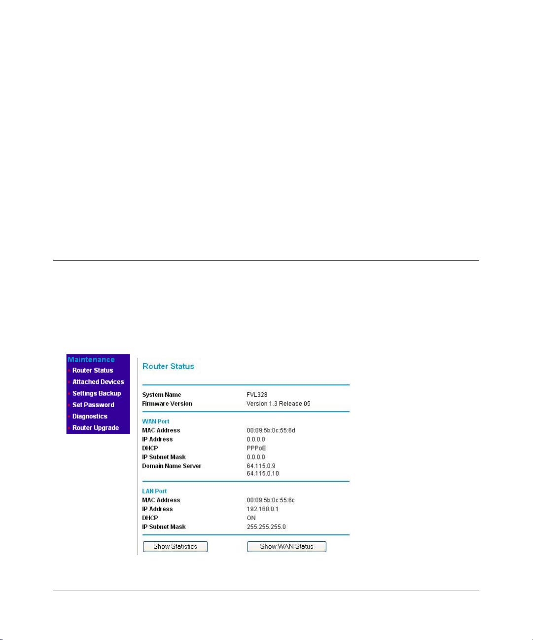
Chapter 5
Managing Your Network
This chapter describes how to perform network management tasks with your FVL328 Prosafe
High Speed VPN Firewall.
Network Management Information
The FVL328 provides a variety of status and usage information which is discussed below.
Viewing Router Status and Usage Statistics
From the Main Menu, under Maintenance, select Router Status to view the screen in Figure 5-1.
Figure 5-1: Router Status screen
Managing Your Network 5-1
Page 80

Model FVL328 ProSafe High-Speed VPN Firewall Reference Manual
The Router Status menu provides a limited amount of status and usage information. From the
Main Menu of the browser interface, under Maintenance, select Router Status to view the status
screen, shown in
Figure 5-1.
This screen shows the following parameters:
Table 5-1. Router Status Fields
Field Description
System Name This field displays the Host Name assigned to the firewall in the Basic
Settings menu.
Firmware Version This field displays the firewall firmware version.
WAN Port These parameters apply to the Internet (WAN) port of the firewall.
MAC Address This field displays the Ethernet MAC address being used by the Internet
(WAN) port of the firewall.
IP Address This field displays the IP address being used by the Internet (WAN) port
of the firewall. If no address is shown, the firewall cannot connect to the
Internet.
DHCP If set to None, the firewall is configured to use a fixed IP address on the
WAN.
If set to Client, the firewall is configured to obtain an IP address
dynamically from the ISP
IP Subnet Mask This field displays the IP Subnet Mask being used by the Internet (WAN)
port of the firewall.
Domain Name Servers
(DNS)
LAN Port These parameters apply to the Local (WAN) port of the firewall.
MAC Address This field displays the Ethernet MAC address being used by the Local
IP Address This field displays the IP address being used by the Local (LAN) port of
DHCP If set to OFF, the firewall will not assign IP addresses to local PCs on the
IP Subnet Mask This field displays the IP Subnet Mask being used by the Local (LAN)
This field displays the DNS Server IP addresses being used by the
firewall. These addresses are usually obtained dynamically from the ISP.
(LAN) port of the firewall.
the firewall. The default is 192.168.0.1
LAN.
If set to ON, the firewall is configured to assign IP addresses to local
PCs on the LAN.
port of the firewall. The default is 255.255.255.0
5-2 Managing Your Network
Page 81

Model FVL328 ProSafe High-Speed VPN Firewall Reference Manual
Click on the “Show Statistics” button to display firewall usage statistics, as shown in Figure 5-2
below:
Figure 5-2. Router Statistics screen
This screen shows the following statistics:
Table 5-2. Router Statistics Fields
Field Description
System up Time The time elapsed since the last power cycle or reset.
WAN, LAN, or
Serial Port
Status The link status of the port.
TxPkts The number of packets transmitted on this port since reset or manual clear.
RxPkts The number of packets received on this port since reset or manual clear.
Collisions The number of collisions on this port since reset or manual clear.
Tx B/s The current line utilization—percentage of current bandwidth used on this port.
Rx B/s The average line utilization —average CLU for this port.
Up Time The time elapsed since this port acquired the link.
Poll Interval Specifies the intervals at which the statistics are updated in this window. Click on Stop
The statistics for the WAN (Internet), LAN (local), and Serial ports. For each port, the
screen displays:
to freeze the display. Click on Set Interval to set the polling refresh interval.
Managing Your Network 5-3
Page 82

Model FVL328 ProSafe High-Speed VPN Firewall Reference Manual
Viewing Attached Devices
The Attached Devices menu contains a table of all IP devices that the firewall has discovered on
the local network. From the Main Menu of the browser interface, under the Maintenance heading,
select Attached Devices to view the table, shown in
Figure 5-3: Attached Devices menu
For each device, the table shows the IP address, NetBIOS Host Name, if available, and the
Ethernet MAC address. Note that if the firewall is rebooted, the table data is lost until the firewall
rediscovers the devices. To force the firewall to look for attached devices, click the Refresh button.
Figure 5-3
5-4 Managing Your Network
Page 83

Model FVL328 ProSafe High-Speed VPN Firewall Reference Manual
Viewing, Selecting, and Saving Logged Information
The firewall will log security-related events such as denied incoming service requests, hacker
probes, and administrator logins. If you enabled content filtering in the Block Sites menu, the Logs
page shows you when someone on your network tried to access a blocked site. If you enabled
e-mail notification, you'll receive these logs in an e-mail message. If you don't have e-mail
notification enabled, you can view the logs here. An example is shown below.
Figure 5-4: Security Logs menu
Managing Your Network 5-5
Page 84

Model FVL328 ProSafe High-Speed VPN Firewall Reference Manual
Log entries are described below:
Table 5-5: Security Log entry descriptions
Field Description
Date and Time The date and time the log entry was recorded.
Description or
The type of event and what action was taken if any.
Action
Source IP The IP address of the initiating device for this log entry.
Source port and
interface
The service port number of the initiating device, and whether it
originated from the LAN or WAN.
Destination The name or IP address of the destination device or website.
Destination port
and interface
The service port number of the destination device, and whether
it’s on the LAN or WAN.
Log action buttons are described below:
Table 5-6: Security Log action buttons
Field Description
Refresh Click this button to refresh the log screen.
Clear Log Click this button to clear the log entries.
Send Log Click this button to e-mail the log immediately.
Apply Click this button to apply any changed settings.
Cancel Click this button to clear any changed settings.
Changing the Include in Log Settings
You can choose to log additional information. Those optional selections are as follows:
• All incoming and outgoing traffic
• Attempted access to blocked site
• Connections to the Web-based interface of this Router
• Router operation (start up, get time, etc.)
• Known DoS attacks and Port Scans
5-6 Managing Your Network
Page 85

Model FVL328 ProSafe High-Speed VPN Firewall Reference Manual
Enabling the Syslog Feature
You can choose to write the logs to a PC running a SYSLOG program. To use this feature, check
the box under Syslog and enter the IP address of the server where the log file will be written. Then
click Apply to activate the Syslog feature.
Examples of Log Messages
Following are examples of log messages. In all cases, the log entry shows the timestamp as:
Day, Year-Month-Date Hour:Minute:Second
Activation and Administration
Tue, 2002-05-21 18:48:39 - NETGEAR activated
[This entry indicates a power-up or reboot with initial time entry.]
Tue, 2002-05-21 18:55:00 - Administrator login successful - IP:192.168.0.2
Thu, 2002-05-21 18:56:58 - Administrator logout - IP:192.168.0.2
[This entry shows an administrator logging in and out from IP address 192.168.0.2.]
Tue, 2002-05-21 19:00:06 - Login screen timed out - IP:192.168.0.2
[This entry shows a time-out of the administrator login.]
Wed, 2002-05-22 22:00:19 - Log emailed
[This entry shows when the log was e-mailed.]
Dropped Packets
Wed, 2002-05-22 07:15:15 - TCP packet dropped - Source:64.12.47.28,4787,WAN Destination:134.177.0.11,21,LAN - [Inbound Default rule match]
Sun, 2002-05-22 12:50:33 - UDP packet dropped - Source:64.12.47.28,10714,WAN Destination:134.177.0.11,6970,LAN - [Inbound Default rule match]
Sun, 2002-05-22 21:02:53 - ICMP packet dropped - Source:64.12.47.28,0,WAN Destination:134.177.0.11,0,LAN - [Inbound Default rule match]
[These entries show an inbound FTP (port 21) packet, UDP packet (port 6970), and ICMP
packet (port 0) being dropped as a result of the default inbound rule, which states that all
inbound packets are denied.]
Managing Your Network 5-7
Page 86

Model FVL328 ProSafe High-Speed VPN Firewall Reference Manual
Enabling Security Event E-mail Notification
In order to receive logs and alerts by e-mail, you must provide your e-mail information in the
E-Mail subheading:
• Turn e-mail notification on
Check this box if you wish to receive e-mail logs and alerts from the firewall.
• Your outgoing mail server
Enter the name or IP address of your ISP’s outgoing (SMTP) mail server (such as
mail.myISP.com). You may be able to find this information in the configuration menu of your
e-mail program. If you leave this box blank, log and alert messages will not be sent via e-mail.
• Send to this e-mail address
Enter the e-mail address to which logs and alerts are sent. This e-mail address will also be used
as the From address. If you leave this box blank, log and alert messages will not be sent via
e-mail.
You can specify that logs are automatically sent to the specified e-mail address with these options:
• Send alert immediately
Check this box if you would like immediate notification of a significant security event, such as
a known attack, port scan, or attempted access to a blocked site.
5-8 Managing Your Network
Page 87

Model FVL328 ProSafe High-Speed VPN Firewall Reference Manual
• Send logs according to this schedule
Specifies how often to send the logs: Hourly, Daily, Weekly, or When Full.
– Day for sending log
Specifies which day of the week to send the log. Relevant when the log is sent weekly or
daily.
– Time for sending log
Specifies the time of day to send the log. Relevant when the log is sent daily or weekly.
If the Weekly, Daily or Hourly option is selected and the log fills up before the specified
period, the log is automatically e-mailed to the specified e-mail address. After the log is sent,
the log is cleared from the firewall’s memory. If the firewall cannot e-mail the log file, the log
buffer may fill up. In this case, the firewall overwrites the log and discards its contents.
Backing Up, Restoring, or Erasing Your Settings
The configuration settings of the FVL328 Firewall are stored in a configuration file in the firewall.
This file can be backed up to your computer, restored, or reverted to factory default settings. The
procedures below explain how to do these tasks.
Procedure 5-2: Backing Up the Configuration to a File
1. Log in to the firewall at its default LAN address of http://192.168.0.1 with its default User
Name of
address you have chosen for the firewall.
Managing Your Network 5-9
admin, default password of password, or using whatever password and LAN
Page 88

Model FVL328 ProSafe High-Speed VPN Firewall Reference Manual
2. From the Maintenance heading of the Main Menu, select the Settings Backup menu as seen in
Figure 5-7.
Figure 5-7: Settings Backup menu
3. Click Backup to save a copy of the current settings.
4. Store the .cfg file on a computer on your network.
5-10 Managing Your Network
Page 89

Model FVL328 ProSafe High-Speed VPN Firewall Reference Manual
Procedure 5-3: Restoring a Configuration from a File
1. Log in to the firewall at its default LAN address of http://192.168.0.1 with its default user
name of
admin, default password of password, or using whatever Password and LAN
address you have chosen for the firewall.
2. From the Maintenance heading of the Main Menu, select the Settings Backup menu as seen in
Figure 5-7.
3. Under Restore Saved Settings from File, enter the full path to the file on your network or click
the Browse button to browse to the file.
4. When you have located the .cfg file, click the Restore button to upload the file to the firewall.
5. The firewall will then reboot automatically.
Procedure 5-4: Erasing the Configuration
It is sometimes desirable to restore the firewall to the factory default settings. This can be done by
using the Erase function.
1. To erase the configuration, from the Maintenance Settings Backup menu, click the Erase
button under Revert to factory default settings.
2. The firewall will then reboot automatically.
After an erase, the firewall's password will be password, the LAN IP address will be
192.168.0.1, and the router's DHCP client will be enabled.
Note: To restore the factory default configuration settings without knowing the login password or
IP address, you must use the Default Reset button on the rear panel of the firewall. See
“Using the
Default Reset Button“ on page 7-7.
Managing Your Network 5-11
Page 90

Model FVL328 ProSafe High-Speed VPN Firewall Reference Manual
Running Diagnostic Utilities and Rebooting the Router
The FVL328 Firewall has a diagnostics feature. You can use the diagnostics menu to perform the
following functions from the firewall:
• Ping an IP Address to test connectivity to see if you can reach a remote host.
• Perform a DNS Lookup to test if an Internet name resolves to an IP address to verify that the
DNS server configuration is working.
• Display the Routing Table to identify what other routers the router is communicating with.
• Trace the Routing Path to identify any connectivity or congestion problems in the network.
• Reboot the Router to enable new network configurations to take effect or to clear problems
with the router’s network connection.
Note: If you are troubleshooting a network connectivity problem and want to Ping the FVL328, be
sure it is configured to respond to a Ping on the Internet WAN port by checking the checkbox seen
“Rules menu“ on page 3-6. However, to preserve a high degree of security, you should turn off
in
this feature when you are finished with your diagnostic testing.
From the Main Menu of the browser interface, under the Maintenance heading, select the Router
Diagnostics heading to display the menu shown below. Then select the function you wish to
activate.
Figure 5-8: Diagnostics menu
5-12 Managing Your Network
Page 91

Model FVL328 ProSafe High-Speed VPN Firewall Reference Manual
Enabling Remote Management
Using the Remote Management page, you can allow a user or users on the Internet to configure,
upgrade and check the status of your NETGEAR Cable/DSL ProSafe VPN Firewall.
Note: Be sure to change the router's default password to a very secure password. The
ideal password should contain no dictionary words from any language, and should be a
mixture of letters (both upper and lower case), numbers, and symbols. Your password
can be up to 30 characters.
Procedure 5-5: Configuring Remote Management
1. Log in to the firewall at its default LAN address of http://192.168.0.1 with its default user
name of
you have chosen for the firewall.
2. Select the Allow Remote Management check box.
admin, default password of password, or using whatever password and LAN address
3. Specify what external addresses will be allowed to access the firewall’s remote management.
Note: For security reasons, restrict access to as few external IP addresses as practical.
a. To allow access from any IP address on the Internet, select Everyone.
b. To allow access from a range of IP addresses on the Internet, select IP address range.
Enter a beginning and ending IP address to define the allowed range.
c. To allow access from a single IP address on the Internet, select Only this PC.
Enter the IP address that will be allowed access.
4. Specify the Port Number that will be used for accessing the management interface.
Web browser access normally uses the standard HTTP service port 80. For greater security,
you can change the remote management web interface to a custom port by entering that
number in the box provided. Choose a number between 1024 and 65535, but do not use the
number of any common service port. The default is 8080, which is a common alternate for
HTTP.
5. Click Apply to have your changes take effect.
Managing Your Network 5-13
Page 92

Model FVL328 ProSafe High-Speed VPN Firewall Reference Manual
When accessing your router from the Internet, the Secure Sockets Layer (SSL) will be enabled.
You will enter https:// and type your router's WAN IP address into your browser's Address (in IE)
or Location (in Netscape) box, followed by a colon (:) and the custom port number. For example, if
your external address is 134.177.0.123 and you use port number 8080, enter in your browser:
https://134.177.0.123:8080
Upgrading the Router’s Firmware
The software of the FVL328 Firewall is stored in FLASH memory, and can be upgraded as new
software is released by NETGEAR.
Upgrade files can be downloaded from NETGEAR's website. If the upgrade file is compressed
(.ZIP file), you must first extract the binary (.BIN or .IMG) file before uploading it to the firewall.
The Web browser used to upload new firmware into the firewall must support HTTP uploads. Use
Microsoft Internet Explorer 5.0 or Netscape Navigator 4.7 and above.
Procedure 5-1: Upgrading the Router
1. Download and unzip the new software file from NETGEAR.
2. Log in to the firewall at its default LAN address of http://192.168.0.1 with its default user
name of
you have chosen for the firewall.
3. From the Main Menu of the browser interface, under the Maintenance heading, select the
Router Upgrade heading
5-14 Managing Your Network
admin, default password of password, or using whatever password and LAN address
to display the menu shown in Figure 5-9.
Figure 5-9: Router Upgrade menu
Page 93

Model FVL328 ProSafe High-Speed VPN Firewall Reference Manual
4. In the Router Upgrade menu, click Browse to locate the binary (.BIN or .IMG) upgrade file.
5. Click Upload.
Note: When uploading software to the firewall, it is important not to interrupt the Web
browser by closing the window, clicking a link, or loading a new page. If the browser is
interrupted, it may corrupt the software. When the upload is complete, your firewall will
automatically restart. The upgrade process will typically take about one minute. In some
cases, you may need to clear the configuration and reconfigure the firewall after
upgrading.
Managing Your Network 5-15
Page 94

Model FVL328 ProSafe High-Speed VPN Firewall Reference Manual
5-16 Managing Your Network
Page 95
Chapter 6
Advanced Configuration
This chapter describes how to configure the advanced features of your FVL328 Prosafe High
Speed VPN Firewall.
Configuring Advanced Security
The FVL328 Prosafe High Speed VPN Firewall provides a variety of advanced features, such as:
• Setting up a Demilitarized Zone (DMZ) Server
• The flexibility of configuring your LAN TCP/IP settings
These features are discussed below.
Setting Up a Default DMZ Server
The default DMZ server feature is helpful when using some online games and videoconferencing
applications that are incompatible with NAT. The firewall is programmed to recognize some of
these applications and to work properly with them, but there are other applications that may not
function well. In some cases, one local PC can run the application properly if that PC’s IP address
is entered as the default DMZ server.
Note: For security, you should avoid using the default DMZ server feature. When a
computer is designated as the default DMZ server, it loses much of the protection of the
firewall, and is exposed to many exploits from the Internet. If compromised, the
computer can be used to attack your network.
Advanced Configuration 6-1
Page 96

Model FVL328 ProSafe High-Speed VPN Firewall Reference Manual
Incoming traffic from the Internet is normally discarded by the firewall unless the traffic is a
response to one of your local computers or a service that you have configured in the Ports menu.
Instead of discarding this traffic, you can have it forwarded to one computer on your network. This
computer is called the Default DMZ Server.
Procedure 6-1: Assigning a Default DMZ Server
1. Click Default DMZ Server.
2. Type the IP address for that server.
3. Click Apply.
Responding to Ping on Internet WAN Port
If you want the firewall to respond to a 'ping' from the Internet, click the ‘Respond to Ping on
Internet WAN Port’ check box. This should only be used as a diagnostic tool, since it allows your
firewall to be discovered. Don't check this box unless you have a specific reason to do so.
Configuring LAN IP Settings
The LAN IP Setup menu allows configuration of LAN IP services such as DHCP and RIP. These
features can be found under the Advanced heading in the Main Menu of the browser interface.
LAN TCP/IP Setup
The firewall is shipped preconfigured to use private IP addresses on the LAN side, and to act as a
DHCP server. The firewall’s default LAN IP configuration is:
• LAN IP addresses—192.168.0.1
• Subnet mask—255.255.255.0
These addresses are part of the IETF-designated private address range for use in private networks,
and should be suitable in most applications. If your network has a requirement to use a different IP
addressing scheme, you can make those changes.
6-2 Advanced Configuration
Page 97

Model FVL328 ProSafe High-Speed VPN Firewall Reference Manual
The LAN TCP/IP Setup parameters are:
• IP Address
This is the LAN IP address of the firewall.
• IP Subnet Mask
This is the LAN Subnet Mask of the firewall. Combined with the IP address, the IP Subnet
Mask allows a device to know which other addresses are local to it, and which must be reached
through a gateway or router.
• RIP Direction
RIP (Router Information Protocol) allows a router to exchange routing information with other
routers. The RIP Direction selection controls how the firewall sends and receives RIP packets.
Both is the default.
— When set to Both or Out Only, the firewall will broadcast its routing table periodically.
— When set to Both or In Only, it will incorporate the RIP information that it receives.
— When set to None, it will not send any RIP packets and will ignore any RIP packets
received.
• RIP Version
This controls the format and the broadcasting method of the RIP packets that the router sends.
It recognizes both formats when receiving. By default, this is set for RIP-1.
— RIP-1 is universally supported. RIP-1 is probably adequate for most networks, unless you
have an unusual network setup.
— RIP-2 carries more information. Both RIP-2B and RIP-2M send the routing data in RIP-2
format.
— RIP-2B uses subnet broadcasting.
— RIP-2M uses multicasting.
Note: If you change the LAN IP address of the firewall while connected through the
browser, you will be disconnected. You must then open a new connection to the new IP
address and log in again.
MTU Size
The normal MTU (Maximum Transmit Unit) value for most Ethernet networks is 1500 bytes. For
some ISPs, particularly some using PPPoE, you may need to reduce the MTU. This is rarely
required, and should not be done unless you are sure it is necessary for your ISP connection.
Advanced Configuration 6-3
Page 98

Model FVL328 ProSafe High-Speed VPN Firewall Reference Manual
Any packets sent through the firewall that are larger than the configured MTU size will be
repackaged into smaller packets to meet the MTU requirement. To change the MTU size:
1. Under MTU Size, select Custom.
2. Enter a new size between 64 and 1500.
3. Click Apply to save the new configuration.
DHCP
By default, the firewall will function as a DHCP (Dynamic Host Configuration Protocol) server,
allowing it to assign IP, DNS server, and default gateway addresses to all computers connected to
the router's LAN. The assigned default gateway address is the LAN address of the firewall. IP
addresses will be assigned to the attached PCs from a pool of addresses specified in this menu.
Each pool address is tested before it is assigned to avoid duplicate addresses on the LAN.
For most applications, the default DHCP and TCP/IP settings of the firewall are satisfactory. See
“IP Configuration by DHCP” on page B-10 for an explanation of DHCP and information about
how to assign IP addresses for your network.
Using the Router as a DHCP Server
If another device on your network will be the DHCP server, or if you will manually configure the
network settings of all of your computers, clear the ‘Use router as DHCP server’ check box.
Otherwise, leave it checked.
Specify the pool of IP addresses to be assigned by setting the Starting IP Address and Ending IP
Address. These addresses should be part of the same IP address subnet as the firewall’s LAN IP
address. Using the default addressing scheme, you should define a range between 192.168.0.2 and
192.168.0.253, although you may wish to save part of the range for devices with fixed addresses.
The firewall will deliver the following parameters to any LAN device that requests DHCP:
• An IP Address from the range you have defined
• Subnet Mask
• Gateway IP Address is the firewall’s LAN IP address
• Primary DNS Server, if you entered a Primary DNS address in the Basic Settings menu;
otherwise, the firewall’s LAN IP address
• Secondary DNS Server, if you entered a Secondary DNS address in the Basic Settings menu
6-4 Advanced Configuration
Page 99

Model FVL328 ProSafe High-Speed VPN Firewall Reference Manual
• WINS Server, short for Windows Internet Naming Service Server, determines the IP
address associated with a particular Windows computer. A WINS server records and
reports a list of names and IP addresses of Windows PCs on its local network. If you
connect to a remote network that contains a WINS server, enter the server’s IP address
here. This allows your PCs to browse the network using the Network Neighborhood
feature of Windows.
Reserved IP Addresses
When you specify a reserved IP address for a PC on the LAN, that PC will always receive the
same IP address each time it accesses the firewall’s DHCP server. Reserved IP addresses should be
assigned to servers that require permanent IP settings.
To reserve an IP address:
1. Click the Add button.
2. In the IP Address box, type the IP address to assign to the PC or server.
Choose an IP address from the router’s LAN subnet, such as 192.168.0.X.
3. Type the MAC Address of the PC or server.
Note: If the PC is already present on your network, you can copy its MAC address from the
Attached Devices menu and paste it here.
4. Click Apply to enter the reserved address into the table.
Note: The reserved address will not be assigned until the next time the PC contacts the router's
DHCP server. Reboot the PC or access its IP configuration and force a DHCP release and
renew.
To edit or delete a reserved address entry:
1. Click the button next to the reserved address you want to edit or delete.
2. Click Edit or Delete.
Procedure 6-2: Configuring LAN TCP/IP Setup
1. Log in to the firewall at its default LAN address of http://192.168.0.1 with its default user
name of
you have chosen for the firewall.
Advanced Configuration 6-5
admin, default password of password, or using whatever password and LAN address
Page 100

Model FVL328 ProSafe High-Speed VPN Firewall Reference Manual
2. From the Main Menu, under Advanced, click the LAN IP Setup link to view the menu, shown
Figure 6-1
in
Figure 6-1: LAN IP Setup Menu
3. Enter the TCP/IP, MTU, or DHCP parameters.
4. Click Apply to save your changes.
Configuring Dynamic DNS
If your network has a permanently assigned IP address, you can register a domain name and have
that name linked with your IP address by public Domain Name Servers (DNS). However, if your
Internet account uses a dynamically assigned IP address, you will not know in advance what your
IP address will be, and the address can change frequently. In this case, you can use a commercial
dynamic DNS service, which will allow you to register your domain to their IP address, and will
forward traffic directed to your domain to your frequently-changing IP address.
The firewall contains a client that can connect to a dynamic DNS service provider. To use this
feature, you must select a service provider and obtain an account with them. After you have
configured your account information in the firewall, whenever your ISP-assigned IP address
changes, your firewall will automatically contact your dynamic DNS service provider, log in to
your account, and register your new IP address.
6-6 Advanced Configuration
 Loading...