

Page 1

TABLE OF CONTENTS
CHAPTER 1: SWITCH MANAGEMENT OVERVIEW......................................................................................................3
CHAPTER 2: Getting Started..........................................................................................................................................4
Network with DHCP server:...........................................................................................................................................4
Smart Wizard Discovery > Discover.......................................................................................................................... 4
Smart Wizard Discovery > Web Access.................................................................................................................... 5
Web Management...................................................................................................................................................... 6
Network without DHCP server................................................................................................................................... 6
Smart Wizard Discovery > Configuration Setting > Default....................................................................................... 7
CHAPTER 3: Software Upgrade Procedure................................................................................................................11
CHAPTER 4: Smart Wizard Discovery Utility Program.............................................................................................13
Main Screen.................................................................................................................................................................13
Main Screen > Device List > Discover..................................................................................................................... 15
Main Screen Switch Setting > Configuration Setting.............................................................................................. 16
Main Screen > Switch Setting > Password Change................................................................................................ 16
Main Screen > Switch Setting > Web Access.......................................................................................................... 17
Main Screen > Switch Setting > Firmware Upgrade................................................................................................ 18
Main Screen > Switch Setting > Exit........................................................................................................................ 18
CHAPTER 5: Configuring the Device Using YOUR BROWSER................................................................................19
Getting Started......................................................................................................................................................... 20
Opening the NETGEAR Home Page for the FS700TS-Series Switch.................................................................... 20
Understanding the Home Page ...............................................................................................................................21
Using The NETGEAR Web Management System Buttons..................................................................................... 22
Device Management Buttons................................................................................................................................... 24
Resetting the System............................................................................................................................................... 25
Defining Device Information.........................................................................................................................................26
Viewing the Device Zoom View............................................................................................................................... 26
Viewing the Device Status...........................................................................................................................................27
Managing Stacking.......................................................................................................................................................29
Operation Modes ..................................................................................................................................................... 29
Understanding Stack Topology................................................................................................................................29
Stacking Ring Topology........................................................................................................................................... 29
Stacking Ports.......................................................................................................................................................... 30
Stacking Members and Unit ID................................................................................................................................30
Removing and Replacing Stacking Members.......................................................................................................... 30
Inserting a Stacking Member................................................................................................................................... 31
Exchanging Stacking Members............................................................................................................................... 31
Switching the Stacking Master................................................................................................................................. 31
Configuring Stacking................................................................................................................................................ 32
Configuring Device Security.........................................................................................................................................34
Defining Port Authentication Properties.......................................................................................................................34
Defining Port Authentication.................................................................................................................................... 36
Viewing EAP Statistics............................................................................................................................................. 38
Enabling Storm Control............................................................................................................................................ 40
Port Security ............................................................................................................................................................42
Configuring Passwords............................................................................................................................................ 44
Viewing System Logs...................................................................................................................................................45
Logs Configuration................................................................................................................................................... 46
Viewing the Memory Logs........................................................................................................................................ 48
Viewing Flash Logs.................................................................................................................................................. 49
Defining Server Logs ............................................................................................................................................... 50
Page 1
Page 2

Configuring Power over Ethernet.................................................................................................................................52
Configuring Interfaces..................................................................................................................................................55
Configuring VLANs .................................................................................................................................................. 62
Defining IP Addresses ............................................................................................................................................. 67
Defining the Forwarding Address Tables................................................................................................................. 70
Defining Dynamic Addresses.......................................................................................................................................71
Configuring the Spanning Tree Protocol.................................................................................................................. 74
Defining STP on Interfaces...................................................................................................................................... 76
Configuring Quality of Service................................................................................................................................. 78
Defining QoS Queues.............................................................................................................................................. 81
Configuring Bandwidth Settings............................................................................................................................... 82
Mapping CoS Values to Queues ............................................................................................................................. 84
Mapping DSCP Values to Queues .......................................................................................................................... 85
Configuring SNMP Security.........................................................................................................................................86
Defining SNMP Engine ID........................................................................................................................................ 87
Defining SNMP Users..................................................................................................................................................88
Defining SNMP Groups................................................................................................................................................90
Defining SNMP Views..................................................................................................................................................93
Defining SNMP Communities ......................................................................................................................................95
Trap Station Management ...........................................................................................................................................99
SNMPv1, 2c Notification Recipient........................................................................................................................ 100
SNMPv3 Notification Recipient.............................................................................................................................. 100
Global Trap Settings.............................................................................................................................................. 102
Trap Filter Settings................................................................................................................................................. 103
Managing System Files.......................................................................................................................................... 105
Monitoring the Device................................................................................................................................................107
Configuring Port Mirroring...................................................................................................................................... 107
Performing Copper Cable Tests............................................................................................................................ 110
Performing Optical Transceiver Tests................................................................................................................... 112
Managing RMON Statistics........................................................................................................................................113
Viewing RMON Statistics....................................................................................................................................... 113
Resetting RMON Statistics Counters..................................................................................................................... 114
Configuring RMON History.................................................................................................................................... 115
Defining RMON Events.......................................................................................................................................... 119
Resetting the Factory Default Values.................................................................................................................... 124
APPENDIX A: DEFAULT SETTINGS........................................................................................................................125
Page 2
Page 3

CHAPTER 1: SWITCH MANAGEMENT OVERVIEW
This section gives an overview of switch management, including the methods you can use to manage your NETGEAR Prosafe FS700TS family of
10/100 Stackable Smart Switches with Gigabit Ports.
Your NETGEAR Prosafe FS700TS family of 10/100 Stackable Smart Switches with Gigabit Ports contains software for viewing, changing, and
monitoring the way it works. This management software is not required for the switch to work. You can use the 10/100 Mbps ports and the built-in
Gigabit ports without using the management software. However, the management software allows you configure ports, VLAN and Trunking
features and also improve the efficiency of the switch and, as a result, improve the overall performance of your network. The Switch gives you the
flexibility to access and manage the switch using any of the following methods:
• Smart Wizard Discovery Utility program
• Web browser interface
After you power-up the switch for the first time, you can configure it using the Smart Wizard Discovery Utility or a Web browser. Please refer to the
screenshots in following pages for the Smart Wizard Discovery Utility and Web Management GUI. Each of these management methods has
advantages. Table 1-1 compares the three management methods.
Table 1 – 1: Comparing Switch Management Methods
Management Method Advantages
Smart Wizard Discovery
Utility program
Web browser Can be accessed from any location via the switch’s IP
For a more detailed discussion of the Smart Wizard Discovery Utility Program, see section 4. For a more detailed discussion of the Web Browser
Interface, see section 5.
No IP address or subnet needed
Show all switches on the network
User-friendly interface
Firmware upgradeable
address
Password protected
Ideal for configuring the switch remotely
Compatible with Internet Explorer and Netscape Navigator
Web browsers
Intuitive browser interface
Most visually appealing
Extensive switch configuration allowed
Configuration backup for duplicating settings to other
switches
Page 3
Page 4

CHAPTER 2: GETTING STARTED
This section will walk you through the steps to start managing your FS700TS-series switch. This section will cover how to get started in a network
with a DHCP server (most common) as well as if you do not have a DHCP server.
Network with DHCP server:
1. Connect the FS700TS-series switch to a DHCP network.
2. Power on FS700TS-series switch by plugging in power core.
3. Install the Smart Wizard Discovery Utility program on your computer.
4. Start the Smart Wizard Discovery utility. (Section 4 has detailed instructions on the Smart Wizard Discovery utility)
5. Click Discover for the Smart Wizard Discovery to find your FS700TS-series switch. You should see something similar to Figure 2-1.
Smart Wizard Discovery > Discover
Figure 2 - 1: Smart Wizard Discovery Utility Main Screen
6. Select your switch by clicking on it. Then click on Web Access, as highlighted in Figure 2-2.
Page 4
Page 5

Smart Wizard Discovery > Web Access
Figure 2 - 2: Web Access
Start managing your switch via your web browser. The default password is ‘password’. For a detailed description on web management, please refer
to Section 5.
Page 5
Page 6

Web Management
Figure 2 - 3: Web Management Front page after click “web access” on the Smart Wizard Discovery Utility
Network without DHCP server
1. Connect FS700TS-series switch to your existing network.
2. Power on FS700TS-series switch by plugging in power cord (Default IP is 192.168.0.239).
3. Install the Smart Wizard Discovery Utility program on your computer
4. Start the Smart Wizard Discovery utility. (Section 4 has detailed instructions on the Smart Wizard Discovery Utility)
5. Click Discover for the Smart Wizard Discovery Utility to find your FS700TS-series switch. You should see a something similar to Figure
2-1.
6. Click on Configuration Setting (See Figure 2-4).
Note: You can always assign a Static IP address to your FS700TS-series switch, even if your network does not have a DHCP server.
Page 6
Page 7

Smart Wizard Discovery > Configuration Setting > Default
Figure 2 - 4: Configuration Setting
7. Choose Disable on DHCP. See Figure 2-5.
8. Enter your IP address, Gateway and Subnet, and then type your password and click “Set”. Please make sure your PC and FS700TSseries switch are in the same subnet (See Figure 2-6.).
Page 7
Page 8

Smart Wizard Discovery > Configuration Setting > Assign Static IP
Figure 2 - 5: Manually Setting IP Address
Page 8
Page 9

NIC Setting on the PC that Accesses the FS700TS-Series Switch
Figure 2-6: Setting IP Address and Subnet Mask
1. Select your switch by clicking on it. Then click on Web Access, as highlighted in Figure 2-2.
2. Start managing your switch via your web browser. The default password is ‘password’. For a detailed description on web management access,
please refer to Section 5.
Page 9
Page 10

Web Management
Figure 2 - 7: Web Management Front Page after Click “Web Access” on the Smart Wizard Discovery Utility
Page 10
Page 11

CHAPTER 3: SOFTWARE UPGRADE PROCEDURE
The application software for the FS700TS-series switch is upgradeable, enabling your switch to take advantage of improvements and additional
features as they become available. The upgrade procedure and the required equipment are described in the following section.
The upgrade procedure is as follows:
1. Save the new firmware to your computer.
2. Start the Smart Wizard Discovery Utility program.
3. Select your switch by clicking on it. Then click on Firmware Upgrade, as highlighted in Figure 3-1.
Figure 3 - 1: Select the Switch you Want to Upgrade and Click Firmware Upgrade
Page 11
Page 12

Figure 3 - 2: Locate New Firmware
4. Enter the location of the new firmware in the Firmware path below Firmware setting. Alternatively, you can click Browse to locate the file.
Enter following path, tftp://{tftp address}/{file name}.
5. Click Start to download the new firmware file in non-volatile memory. The system software is automatically loaded to all stacking
members.
Figure 3 - 3: Enter Password and click Start
Note: Once the system finishes firmware upgrade process, the switch will automatically reboot. The Smart Wizard Discovery Utility determines the
success of the upgrade process based on the success of the system reboot.
Page 12
Page 13

CHAPTER 4: SMART WIZARD DISCOVERY UTILITY PROGRAM
The Smart Wizard Discovery Utility program is a user-friendly, easy to install tool. Using this program, you can view and configure all the FS700TSseries Smart Switches in your network.
The installation of the Smart Wizard Discovery Utility is as follows:
1. Insert the disc into your CD-ROM drive.
2. Select the \Software folder or click ‘install’ from Browser auto-executed after inserting the Resource CD.
3. Run the Setup program to install the Smart Wizard Discovery Utility.
4. The Installation Wizard will guide you through.
5. Run the ‘Smart Wizard Discovery Utility’ from the window start bar.
Main Screen
The main screen displays the available functions. As shown in Figure 4-1, there are six function items to choose from:
• Discover
• Configuration Setting
• Password Change
• Web Access
• Firmware Upgrade
• Exit
Page 13
Page 14

Figure 4 - 1: Smart Wizard Discovery Utility Main Screen
Page 14
Page 15

Main Screen > Device List > Discover
The Smart Wizard Discovery Utility can discover all switches currently connected on the network. Click ‘Discover’ to view the following switch
information of any listed switch:
• MAC Address
• IP Address
• Protocol Version
• Product Name
• System Name
• Location
• DHCP
• Subnet Mask
• Gateway
Figure 4 - 2: Main Screen: Device List > Discover
By double-clicking a listed switch, you can open the Web management for that switch. Alternatively, you can select a switch by clicking on it once,
and then clicking Web Access. For more information on Web management, see Section 5.
Page 15
.
Page 16

Main Screen Switch Setting > Configuration Setting
Select a switch by clicking on it. Then click Configuration Setting.
The following screen pops up, enabling you modify:
• System Name — This field is to help you keep track of your switches. It can be any combination of letters and/or numbers.
• Location — This field is to help you keep track of where this switch is. It can be any combination of letters and/or numbers.
• Password — The default password is ‘password’. You must enter your password for and modifications to take affect.
• DHCP — DHCP automatically obtains the IP information for the switch.
Figure 4 - 3: Main Screen: Switch Setting > Configuration Setting
• System Name — Any desired description for System Name.
• Location — Any desired description for Location.
• Password — The default password is ‘password’.
• DHCP — This function is enabled by default. Click ‘Disable’ to abort the function.
Main Screen > Device Setting > Configuration Setting > Set
Click ‘Set’ to enable new settings. You must enter your password for these settings to be accepted.
Main Screen > Device Setting > Configuration Setting > Cancel
Click ‘Cancel’ to abort the above settings.
Main Screen > Switch Setting > Password Change
6. Click ‘Password Change’ from the Switch Setting section. The following screen pops up as shown in Figure 4-4.
Figure 4 - 4: Main Screen: Switch Setting > Password Change
• New Password — Type any desired password. Passwords are case-sensitive and can have a maximum of 20 characters.
Page 16
Page 17

• Confirm Password— Re-type the new password to confirm it.
• Old Password — The default password is ‘password’.
7. Click ‘Set’ to enable new password.
Main Screen > Switch Setting > Web Access
8. Select a listed switch from the Device List section. Then click Web Access from the Switch Setting (see Figure 4-5).
9. Enter the default password ‘password’ and click Log in.
For more on Web management, see Section 5.
Figure 4 - 5: Web Management Login Page
Page 17
Page 18

Main Screen > Switch Setting > Firmware Upgrade
10. Click Firmware Upgrade from the Switch Setting section. The following screen will pop up.
Figure 4 - 6: Main Screen: Switch Setting > Firmware Upgrade
• Firmware Path — The location of the new firmware. If you don’t know, you can click Browse to locate file.
• Password — The default password is ‘password’.
• Upgrade State — Shows upgrading in progress.
11. Click Start to start upgrading.
Main Screen > Switch Setting > Exit
• Click Exit from the Switch Setting section to close the Smart Wizard Discovery Utility program.
Page 18
Page 19

CHAPTER 5: CONFIGURING THE DEVICE USING YOUR BROWSER
This section contains information for configuring the device using your web browser and includes the following topics:
• Getting Started
• Resetting the System
• Defining Device Information
• Managing Stacking
• Configuring Device Security
• Viewing System Logs
• Configuring Power over Ethernet
• Configuring Interfaces
• Defining IP Addresses
• Defining the Forwarding Address Tables
• Configuring the Spanning Tree Protocol
• Configuring Quality of Service
• Configuring SNMP Security
• Monitoring the Device
• Managing RMON Statistics
• Resetting the Factory Default Values
Page 19
Page 20

Getting Started
This section describes setting browser interface options and using the home page for the FS700TS-series switch. It includes the following sections:
• Opening the NETGEAR Home Page for the FS700TS-series switch
• Understanding the Home Page for the FS700TS-series switch
• Using the Web Management System Buttons
Opening the NETGEAR Home Page for the FS700TS-Series Switch
The NETGEAR home page for the FS700TS-series switch can be accessed from any PC with a web browser.
To start the application:
1. Open a web browser.
2. Enter the device IP address in the address bar.
3. Press Enter. The Login Page appears.
4. Enter a password.
5. Click
Figure 5 - 1: Login Page
. The FS700TS home page displays.
Page 20
Page 21

Understanding the Home Page
The NETGEAR FS700TS home page contains the following views:
• Navigation Pane — Located on the left side of the FS700TS home page. The Navigation Pane provides an expandable Navigation Pane of
the features and their component. The Navigation Pane is marked as 1 in Figure 5 - 2.
• Device View — Located on the right side of the FS700TS home page. The Device View provides a view of the device, information or table
area, and of configuration instructions.
• Information Buttons — Located in the upper right corner of the home page, the inf ormation buttons provide connections to NETGEAR
support and the online manual. See item 3 in Figure 5-2.
Figure 5 - 2: Home Page Components
Navigation Pane
The Navigation Pane contains a list of the different features that can be configured including switching features, ports, spanning tree, VLANs, class
of service, link aggregation (aggregating ports), multicast support, and statistics. The Navigation Pane branches can be expanded to view all the
components under a specific feature or retracted to hide the feature's components.
Device View
The following section describes the different aspects of the Device View. The device provides information about FS728TS/F752TPS/FS752TS, the
different components, and the Work Desk. The Work Desk in the Device View provides a work area that contains device tables, general device
information, and configurable device parameters.
Page 21
Page 22

Using The NETGEAR Web Management System Buttons
This section contains information about the different FS700TS browser interface buttons. The FS700TS web browser provides the following
buttons:
• Information Buttons — Provide access to informational services including technical support, online help, device information, and closing the
browser.
• Device Management Buttons — Provide an explanation of the management buttons in the NETGEAR FS700TS-series Switch, including the
Add, Delete, Query, and Apply Changes buttons.
Information Buttons
The FS700TS Switch web browser contains the following information buttons:
Table 1 - 1: Information Buttons
Button Description
Opens the NETGEAR support page. The NETGEAR technical
support page URL is
Opens the Online Help.
Support Button
The Support Page contains information for accessing NETGEAR technical support. To access the technical support page:
• Click Support on the NETGEAR home page. The NETGEAR Support Page opens:
http://kbserver.netgear.com/
Figure 5 - 3: NETGEAR Support Page
Page 22
Page 23

Page 23
Page 24

Device Management Buttons
The NETGEAR FS700TS Switch web browser GUI management buttons allow network managers to easily configure the device from remote
locations. The FS700TS Switch web browser GUI contains the following management buttons:
Table 1 - 2: Device Management Buttons
Button Description
Applies set changes to the device.
Adds information to tables or
information windows.
Refreshes device information.
Resets statistics counters.
Performs copper cables.
Restores the factory defaults.
Page 24
Page 25

Resetting the System
The Reboot Page resets the device. Ensure that configuration changes are saved to the device before rebooting. Configuration changes that are
not saved are lost. There are two options to reboot.
• Rebooting a particular unit.
• Rebooting the entire stack.
To open the Reboot Page:
1. Click Reboot. The Reboot Page opens.
Figure 5 - 4: Reboot Page
The Reboot Page contains the following field:
• Reset Unit No. — Choose the port to be reset or select the option Stack to reboot all stacking members.
2. Click
. The device is reset.
Page 25
Page 26

Defining Device Information
This section contains the following topics:
• Viewing the Device Zoom View
• Viewing the Device Status
Viewing the Device Zoom View
The System Zoom Page provides a graphic representation of the device, including the port and LED statuses.
Figure 5 - 5: System Zoom Page
Page 26
Page 27

Viewing the Device Status
The Switch Status Page contains parameters for configuring general device information, including the system name, location, contact, the system
MAC Address, System Object ID, System Up Time and MAC addresses, and both software and hardware versions.
1. Click Switch Status. The Switch Status Page opens.
Figure 5 - 6: Switch Status Page
The Switch Status Page contains the following fields:
• Model Name — Displays the device model number and name.
• System Name — Defines the user-defined device name. The field may contain is 0-160 characters.
• System Location — Defines the location where the system is currently running. The field may contain is 0-160 characters.
• System Contact — Defines the name of the contact person. The field may contain is 0-160 characters.
• System Object ID — Displays the vendor’s authoritative identification of the network management subsystem contained in the entity.
• Date — Displays the current date.
• Local Time — Displays the Local time.
• System Up Time — Displays the amount of time since the most recent device reset. The system time is displayed in the following format:
Days, Hours, Minutes, and Seconds. For example, 41 days, 2 hours, 22 minutes and 15 seconds.
• Base MAC Address — Displays the MAC address for each stacking unit.
• Unit Mode — Indicates if the device is currently in stand-alone or stacking mode.
Page 27
Page 28

• Change Mode to Stack — Switches the device from stand-alone to stacking mode.
• Hardware Version — Displays the installed device hardware version number.
• Software Version — Displays the installed software version number.
• Boot Version — Displays the current boot version running on the device.
2. Define the fields.
3. Click
.
Page 28
Page 29

Managing Stacking
All stack members are accessed through a single IP address through which the stack is managed. Stacks are managed using:
• Web-based Interface
• SNMP Management Station
The system supports up to six stacking members per stack to a maximum of 192 ports
During the Stacking setup, one device is selected as the Stacking Master. All other devices are named as stack members, and assigned a unique
Unit ID. The Stack Master provides a Single point of control and management as well as a single interface in which to control and manage the
stack. The device software is downloaded separately for each of the stack members. All units in the stack must be running the same software
version. The Stacking Master maintains switch stacking and configuration. The Stacking Master detects and reconfigures the ports with minimal
operational impact in the event of:
• Unit Failure
• Inter-unit Stacking Link Failure
• Unit Insertion
• Removal of a Stacking Unit
, or devices can operate as stand-alone systems.
Operation Modes
A stack can operate in one of the following modes:
• Stand-alone Mode — Indicates the device is operating as a single unit and is not connected in a stack.
• Stacking Master — Manages the stacking configuration for all stack members.
• Secondary Master — Operates as a backup to the Stacking Master. If the Stacking Master is no longer operating, the Secondary Master
takes over the stack management.
• Stacking Member—Indicates a device within the stacking topology. The stacking member receives its device configuration from the
Stacking Master.
This section provides an introduction to the user interface and includes the following topics:
• Understanding Stack Topology
• Stacking Ring Topology
• Stacking Ports
• Stacking Members and Unit ID
• Removing and Replacing Stacking Members
• Inserting a Stacking Member
• Exchanging Stacking Members
• Switching the Stacking Master
• Configuring Stacking
Understanding Stack Topology
Stacked devices operate in a Ring or chain topology. The Ring topology connects all stacked devices in a circle. Each stacked device accepts data
and sends it to the device to which it is physically connected. The packet continues through the stack until it reaches the destination port. The
system automatically discovers the optimal path by which to send traffic. A chain topology connects stacking members from one to the next. This
provides a single data path flow. The stacking members linked in the middle of the chain are connection to the stacking member on either side of
them. The members on the ends of the chain only have one connection.
Stacking Ring Topology
One of the benefits of the Ring topology is that it offers redundancy in case the connections between two units fail, including the case where a unit
in the stack fails. If a failure occurs in the stacking topology, the stack reverts to Chain Stacking Topology. In the Chain topology, devices operate in
a chain formation. The system automatically switches to a Stacking Failover topology without any system downtime. An SNMP message is
automatically generated, but no stack management action is required. However, the stacking link or stacking member must be repaired to return to
the Ring topology.
After the stacking issues are resolved, the device can be reconnected to the stack without interruption and the Ring topology is restored.
Page 29
Page 30

Stacking Ports
The mode type determines the Gigabit Ethernet ports that are configurable by the user.
• In Stand-alone mode all Gigabit Ethernet ports are available.
• In Stack mode two dedicated Gigabit Ethernet ports are used for stack connection.
The factory default of the device is stacking mode. Use the Stack Management screen to configure a unit to operate in stand-alone mode.
The ports used for stacking can be either the combo ports or the copper ports. By default, the copper ports are reserved for stacking. The Stack
Management screen allows network managers to configure the combo ports as the stacking ports. The factory default of the device is stacking
mode.
Stacking Members and Unit ID
Stacking Unit IDs are essential to the stacking configuration. The stacking operation is determined during the boot process. The Unit ID selected
during the initialization process determines the Operation Mode. For example, if the user selected stand-alone mode, the device boots as a standalone device.
Unit ID 1 and Unit ID 2 are reserved for Master enabled units. Unit IDs 3 to 6 can be defined for stack members. When the Master unit boots or
when inserting or removing a stack member, the Master unit initiates a stacking discovering process.
If two members are discovered with the same Unit ID the stack continues to function, however only the unit with the older join time joins the stack.
A message is sent to the user, notifying that a unit failed to join the stack.
Removing and Replacing Stacking Members
Stacking member 1 and stacking member 2 are Stacking Master enabled units. Unit IDs 1 and 2 are either designated as Master Unit or Secondary
Master Unit. The Stacking Master assignment is performed during the configuration process. One Master enabled stack member is elected Master,
and the other Master enabled stack member is elected Secondary Master, according to the following decision process:
• If only one Stacking Master enabled unit is present, this is the stacking Master.
• If two Stacking Master enabled stacking members are present, and one has been manually configured as the Stacking Master, this is the
Stacking Master.
• If two Master enabled units are present and neither has been manually configured as the Stacking Master, the one with the longer up
time is elected Stacking Master.
• If the two Master enabled stacking members are the same age, Unit 1 is elected Stacking Master.
Two stacking member are considered the same age if they joined the stack within the same ten minute interval. For example, Stack member 2 is
inserted in the first minute of a ten-minute cycle, and Stack member 1 is inserted in fifth minute of the same cycle, the units are considered the
same age. If there are two Master enabled units that are the same age, then Unit 1 is elected master.
The Stacking Master and the Secondary Master maintain a Warm Standby. The Warm Standby ensures that the Secondary Master takes over for
the Stacking Master if a failure occurs. This guarantees that the stack continues to operate normally.
During the Warm Standby, the Master and the Secondary Master are synchronized with the static configuration only. When the Stacking Master is
configured, the Stacking Master must synchronize the Stacking Secondary Master. The Dynamic configuration is not saved, for example,
dynamically learned MAC addresses are not saved.
Each port in the stack has a specific Unit ID, port type, and port number, which is part of both the configuration commands and the configuration
files. Configuration files are managed only from the device Stacking Master. This includes:
• Saving to the FLASH
• Uploading Configuration files to an external TFTP server
• Downloading Configuration files from an external TFTP server
Whenever a reboot occurs, topology discovery is performed, and the master learns all units in the stack. Unit IDs are saved in the unit and are
learned through topology discovery. If a unit attempts to boot without a selected Master, and the unit is not operating in stand-alone mode, the unit
does not boot. For example, if a stack member (unit IDs 3 - 6) is separated from the stack due to a topology failure, the stacking member is no
longer connected to the stack. The device can be booted, but it cannot be managed through the Stacking Master. The network manager can either
reset the device defaults, or correct the topology failure, and reconnect the unit to the stack.
Configuration files are changed only through explicit user configuration. Configuration files are not automatically modified when:
• Units are Added
• Units are Removed
• Units are reassigned Unit IDs
Page 30
Page 31

• Units toggle between Stacking Mode and Stand-alone Mode
Each time the system reboots, the Startup Configuration file in the Master unit is used to configure the stack. If a stack member is removed from the
stack, and then replaced with a unit with the same Unit ID, the stack member is configured with the original device configuration. Only ports that are
physically present are displayed in the FS700TS web pages, and can be configured through the web management system. By default, Unit IDs are
assigned automatically. However, you can use the browser to assign a specific Unit ID; for example, the same unit ID as the unit which was
recently removed."
Inserting a Stacking Member
When a stacking member is inserted into a running stack, it is automatically assigned a unit number. Note that a unit should not be powered up until
it has been connected to the stack. If the user has already configured a Unit ID for the newly joined unit, a new Unit ID is not assigned.
Exchanging Stacking Members
If a stack member with the same Unit ID replaces an existing Unit ID with the same Unit ID, the previous device configuration is applied to the
inserted stack member. If the new inserted device has either more than or less ports than the previous device, the relevant port configuration is
applied to the new stack member.
• If a 24 port switch replaces a 24 port switch, all port configurations remain the same.
• IIf a 48 port switch replaces a 48 port switch, all port configurations remain the same.
• IIf a 48 port switch replaces a 24 port switch, the first 24 ports receive the 24 FE port configuration. The GE port configurations remain the
same. The remaining ports receive the default port configuration.
• IIf a 24 port switch replaces a 48 port switch, the first 24 ports receive the first 24 port configuration. The GE port configurations remain the
same.
The replaced stacking members receives the previous stacking member’s Unit ID.
Switching the Stacking Master
The Secondary Master replaces the Stacking Master if one of the following events occur:
• The Stacking Master fails or is removed from the stack.
• Links from the Stacking Master to the stacking members fails.
• A soft switchover is performed via the web interface.
Switching between the Stacking Master and the Secondary Master results in a limited service loss. Any dynamic tables are relearned if a failure
occurs. The running configuration file is synchronized between Stacking Master and the Secondary Master and continues running on the
Secondary Master.
Page 31
Page 32

Configuring Stacking
The Stack Management page allows network managers to either reset the entire stack or a specific device. Device configuration changes that are
not saved before the device is reset are not saved. A unique Unit ID (1-6) identifies a stack member. This unit number determines the interface-level
configuration that the stack member uses. (The config uration is sa ved and mana ged by th e master unit.). T he st ack managem ent has the following defa ults:
• The stacking mode is set to stackable.
• The stacking cable is copper.
• The stacking numbering method is set to auto-numbering.
To configure stacking:
1. Click Stack Management. The Stack Management Page opens.
Figure 5 - 7: Stack Management Page
The Stack Management Page contains the following fields:
• Switch Stack Control from Unit 1 to Unit 2 — Switches the stack control from the Stack Master to the Backup Master. The possible field
values are:
– Checked —Switches the stack control to the Standby Stack Master.
– Unchecked — Maintains the current stacking control.
• Stacking Ports — Allows the user to decide what cable type is in use.
– Combo Ports Indicates that the combo port is used as the stacking port.
– Copper Ports Indicates that the copper port is used as the stacking port.
• Unit No. — Indicates the stacking member’s current number. Possible values are 1-6.
• Unit No. After Reset — Indicates the stacking member’s future number after the stack is reset. Possible values are 1-6.
Page 32
Page 33

Switching Between Stack Masters:
1. Open the Stack Management Page.
2. Check the Switch Stack Control from Unit 1 to Unit 2 check box.
3. Click
. A confirmation message displays.
Page 33
Page 34

Configuring Device Security
This section contains information for managing both storm control and port security and includes the following topics:
• Enabling Storm Control
• Port Security
Defining Port Authentication Properties
The Port Authentication Properties Page allows network managers to configure network authentication parameters. In addition, Guest VLANs are
enabled from the Properties Page. This section includes the following sections:
• Defining Port Authentication
• Viewing EAP Statistics (Extensible Authentication Protocol)
To define the port authentication properties:
1. Click Security > Port Authentication > Properties. The Port Authentication Properties Page opens.
Figure 5 - 8: Port Authentication Properties Page
The Port Authentication Properties Page contains the following fields:
• Port-based Authentication State — Indicates if Port Authentication is enabled on the device. The possible field values are:
– Enable — Enables port-based authentication on the device.
– Disable — Disables port-based authentication on the device.
• Authentication Method — Specifies the authentication method used for port authentication. The possible field values are:
– None — Indicates that no authentication method is used to authenticate the port.
Page 34
Page 35

– RADIUS — Provides port authentication using the RADIUS server.
– RADIUS, None — Provides port authentication, first using the RADIUS server. If the port is not authenticated, then no authentication
method is used, and the session is permitted.
• Guest VLAN — Specifies whether the Guest VLAN is enabled on the device. The possible field values are:
– Enable — Enables using a Guest VLAN for unauthorized ports. If a Guest VLAN is enabled, the unauthorized port automatically joins the
VLAN selected in the VLAN List field.
– Disable — Disables port-based authentication on the device. This is the default.
• VLAN List — Contains a list of VLANs. The Guest VLAN is selected from the VLAN list.
2. Define the fields.
3. Click
The network authentication properties are set and the device is updated.
Page 35
Page 36

Defining Port Authentication
The Port Authentication Page allows network managers to configure port-based authentication global parameters. To define the port-based
authentication global properties:
1. Click Security > Port Authentication > Port Authentication. The Port Authentication Page opens.
Figure 5 - 9: Port Authentication Page
The Port Authentication Page contains the following fields:
• Unit No. — Indicates the stacking number
• ID — Displays a list of interfaces on which port-based authentication is enabled.
• User Name — Displays the supplicant user name.
• Current Port Control — Displays the current port authorization state.
• Enable Periodic Reauthentication — Permits immediate port reauthentication. The possible field values are:
– Enable — Enables immediate port reauthentication. This is the default value.
– Disable — Disables port reauthentication.
• Reauthentication Period — Displays the time span (in seconds) in which the selected port is reauthenticated. The field default is 3600
seconds.
• Authenticator State — Displays the current authenticator state.
• Quiet Period — Displays the number of seconds that the device remains in the quiet state following a failed authentication exchanges. The
possible field range is 0-65535. The field default is 60 seconds.
• Resending EAP — Defines the amount of time (in seconds) that lapses before EAP requests are resent. The field default is 30 seconds.
• Max EAP Requests — Displays the total amount of EAP requests sent. If a response is not received after the defined period, the
authentication process is restarted. The field default is 2 retries.
Page 36
Page 37

• Supplicant Timeout — Displays the amount of time (in seconds) that lapses before EAP requests are resent to the supplicant. The field
default is 30 seconds.
• Server Timeout — Displays the amount of time (in seconds) that lapses before the device re-sends a request to the authentication server.
The field default is 30 seconds.
• Termination Cause — Indicates the reason for which the port authentication was terminated.
2. Click an ID. The Modify Port Security Page opens:
3. Modify the fields.
4. Click
Figure 5 - 10: Modify Port Security Page
. The port authentication settings are defined and the device is updated.
Page 37
Page 38

Viewing EAP Statistics
The EAP Statistics Page contains information about EAP packets received on a specific port. To view EAP Statistics:
• Click Security > Port Authentication > EAP Statistics. The EAP Statistics Page opens.
Figure 5 - 11: EAP Statistics Page
The EAP Statistics Page contains the following fields:
• Unit No — Indicates the stacking number
• Port — Indicates the port, which is polled for statistics.
• Refresh Rate — Indicates the amount of time that passes before the EAP statistics are refreshed. The possible field values are:
– 15 Seconds.
– 30 Seconds.
– 60 Seconds.
– No Refresh — Indicates that the EAP statistics are not refreshed.
• Frames Receive — Indicates the number of valid EAPOL frames received on the port.
• Frames Transmit — Indicates the number of EAPOL frames transmitted via the port.
• Start Frames Receive — Indicates the number of EAPOL Start frames received on the port.
• Log off Frames Receive — Indicates the number of EAPOL Logoff frames that have been received on the port.
• Respond ID Frames Receive — Indicates the number of EAP Resp/Id frames that have been received on the port.
Page 38
Page 39

• Respond Frames Receive — Indicates the number of valid EAP Response frames received on the port.
• Request ID Frames Transmit — Indicates the number of EAP Req/Id frames transmitted via the port.
• Request Frames Transmit — Indicates the number of EAP Request frames transmitted via the port.
• Invalid Frames Receive — Indicates the number of unrecognized EAPOL frames that have been received by on this port.
• Length Error Frames Receive — Indicates the number of EAPOL frames with an invalid Packet Body Length received on this port.
• Last Frame Version — Indicates the protocol version number attached to the most recently received EAPOL frame.
• Last Frame Source — Indicates the source MAC address attached to the most recently received EAPOL frame.
Page 39
Page 40

Enabling Storm Control
Storm control limits the amount of Multicast and Broadcast frames accepted and forwarded by the device. When Layer 2 frames are forwarded,
Broadcast, and Multicast frames are flooded to all ports on the relevant VLAN. This occupies bandwidth and loads all nodes on all ports.
A Broadcast Storm is a result of an excessive amount of broadcast messages simultaneously transmitted across a network by a single port.
Forwarded message responses are heaped onto the network, straining network resources or causing the network to time out.
Storm control is enabled for all ports by defining the packet type and the rate the packets are transmitted. The system measures the incoming
Broadcast and Multicast frame rates separately on each port, and discards the frames when the rate exceeds a user-defined rate. By default, storm
control is enabled on all ports - broadcast only - with threshold of 200 kbps. Storm Control is enabled by default.
The Storm Control Page provides fields for configuring broadcast storm control.
To enable storm control:
1. Click Security > Traffic Control > Storm Control. The Storm Control Page opens.
Figure 5 - 12: Storm Control Page
The Storm Control Page contains the following fields:
• Unit — Indicates the stacking number.
• Interface — Displays the port number for which the storm control information is displayed.
• Enable Broadcast Control — Indicates if forwarding Broadcast packet types is enabled on the interface for which the storm control
information is displayed. The possible field values are:
– Enable — Enables storm control on all broadcast only ports with threshold of 200 kbps. Enabled is the default.
– Disable — Disables storm control on the interface.
• Broadcast Mode — Specifies the Broadcast mode currently enabled on the device. The possible field values are:
– Unknown Unicast, Multicast & Broadcast — Counts Unicast, Multicast, and Broadcast traffic.
Page 40
Page 41

– Multicast & Broadcast — Counts Broadcast and Multicast traffic together.
– Broadcast Only — Counts only Broadcast traffic.
• Broadcast Rate Threshold — Indicates the maximum rate (kilobits per second) at which unknown packets are forwarded. The range is 70-
250,000. The default value is 200.
2. Click an interface. The Storm Control Modify Page opens:
3. Modify the fields.
4. Click
Figure 5 - 13: Storm Control Modify Page
. Storm control is enabled on the device.
Page 41
Page 42

Port Security
Network security can be increased by limiting access on a specific port only to users with specific MAC addresses. The MAC addresses can be
dynamically learned or statically configured. Locked port security monitors both received and learned packets that are received on specific ports.
Access to the locked port is limited to users with specific MAC addresses. These addresses are either manually defined on the port, or learned on
that port up to the point when it is locked. When a packet is received on a locked port and the packet source MAC address is not tied to that port
(either it was learned on a different port, or it is unknown to the system), the protection mechanism is invoked. It provides the following options for
unauthorized packets arriving at a locked port:
• Forwarded
• Discarded with no trap
• Discarded with a trap
• Shuts down the port
Locked port security also enables storing a list of MAC addresses in the configuration file. The MAC address list can be restored after the device
has been reset. Disabled ports are activated from the Port Security Page.
To define port security:
1. Click Security > Traffic Control > Port Security. The Port Security Page opens.
Figure 5 - 14: Port Security Page
The Port Security Page contains the following fields:
• Interface — Displays the port or LAG name.
• Interface Status — Indicates the host status.
• Learning Mode — Defines the locked port type. The Learning Mode field is enabled only if Locked is selected in the Set Port field. The
possible field values are:
Page 42
Page 43

– Classic Lock - Locks the port, and only forwards packets that have been learned statically or dynamically, prior to locking the port. The
lock is effective immediately.
– Limited Dynamic Lock — Locks the port after a user-defined number of MAC addresses have been dynamically learned on the port. After
the port is locked, packets are forwarded only from MAC addressees that have been learned prior to locking the port.
• Max Entries — Specifies the number of MAC address that can be learned on the port. The Max Entries field is enabled only if Locked is
selected in the Set Port field. In addition, the Limited Dynamic Lock mode is selected. The default is 1.
• Action — Indicates the action to be applied to packets arriving on a locked port. The possible field values are:
– Forward — Forwards packets from an unknown source without learning the MAC address.
– Discard — Discards packets from any unlearned source. This is the default value.
– Shutdown — Discards packets from any unlearned source and shuts down the port. The port remains shut down until reactivated or until
the device is reset.
• Trap — Enables traps when a packet is received on a locked port. The possible field values are:
– Checked — Enables traps.
– Unchecked — Disables traps.
• Trap Frequency (Sec) — The amount of time (in seconds) between traps. The default value is 10 seconds.
2. Click an interface you want to modify. The Modify Port Security Page opens:
3. Modify the fields.
4. Click
Figure 5 - 15: Modify Port Security Page
. The port security settings are defined and the device is updated.
Page 43
Page 44

Configuring Passwords
The Passwords Page contains parameters for configuring device passwords.
To define device passwords:
1. Click System > Password. The Password Page opens:
Figure 5 - 16: Password Page
The Password Page contains the following fields:
• Old Password — Indicates the current password used to access the system.
• New Password — Defines a new password for accessing the system.
• Re-type New Word — Verifies the new password used to access the system.
2. Define the fields.
3. Click
. The password is defined and the device is updated.
Page 44
Page 45

Viewing System Logs
Event messages have a unique format, as per the SYSLOG RFC recommended message format for all error reporting, for example, Syslog+ local
device reporting. Messages are assigned a severity code, and include a message mnemonic, which identifies the source application generating the
message. Messages are filtered based on their urgency or relevancy. The following table contains the Log Severity Levels:
Table 5-3: Severity Levels
Severity Type Severity Level Description
Emergency 0 Indicates that the system is not functioning.
Alert 1 Indicates that the system needs immediate attention.
Critical 2 Indicates that the system is in a critical state.
Error 3 Indicates that a system error has occurred.
Warning 4 Indicates that a system warning is logged.
Notice 5 Indicates that the system is functioning properly, but system notice is logged.
Informational 6 Provides device information.
Debug 7 Provides detailed log information.
This section provides information for managing logs. The logs enable viewing device events in real time, and recording the events for later usage.
Logs record and manage events and report errors and informational messages.
This section includes the following topics:
• Logs Configuration
• Memory Logs
• Flash Logs
• Server Logs
Page 45
Page 46

Logs Configuration
The Logs Configuration Page contains fields for defining which events are recorded to which logs. It contains fields for enabling logs globally, and
parameters for defining logs. Log messages are listed from the highest severity to the lowest severity level. When a severity level is selected, all
severity level choices above the selection are selected automatically.
To enable event logging:
1. Click Logs > Logs Configuration. The Logs Configuration Page opens.
Figure 5 - 17: Logs Configuration Page
The Logs Configuration Page contains the following fields:
• Enable Logging — Indicates if device global logs for Cache, File, and Server Logs are enabled. Console logs are enabled by default. The
possible field values are:
– Checked — Enables device logs.
– Unchecked — Disables device logs.
• Severity — The following are the available log severity levels:
– Emergency — The highest warning level. If the device is down or not functioning properly, an emergency log message is saved to the
specified logging location.
– Alert — The second highest warning level. An alert log is saved, if there is a serious device malfunction; for example, all device features
are down.
– Critical — The third highest warning level. A critical log is saved if a critical device malfunction occurs; for example, two device ports are
not functioning, while the rest of the device ports remain functional.
Page 46
Page 47

– Error — A device error has occurred; for example, if a single port is offline.
– Warning — The lowest level of a device warning. The device is functioning, but an operational problem has occurred.
– Notice — Provides device information.
– Informational — Provides device information.
– Debug — Provides debugging messages.
• RAM Logs — Defines the minimum severity level from which logs are sent to the RAM Log kept in RAM (Cache).
• Log File — Defines the minimum severity level from which logs are sent to the log file kept in FLASH memory.
2. Define the Enable Logging and Severity fields.
3. Click
. The log parameters are set and the device is updated.
Page 47
Page 48

Viewing the Memory Logs
The Memory Logs Page contains all system logs in a chronological order that are saved in RAM (Cache).
To view the Memory Logs:
• Click Logs > Memory Logs. The Memory Logs Page opens.
Figure 5 - 18: Memory Logs Page
The Memory Logs Page contains the following fields:
• ID – Displays the table entry number.
• Log Index — Displays the log number.
• Log Time — Displays the time at which the log was generated.
• Severity — Displays the log severity.
• Description — Displays the log message text.
Page 48
Page 49

Viewing Flash Logs
The Flash Logs Page contains information about log entries saved to the log file in Flash, including the time the log was generated, the log severity,
and a description of the log message. The message log is available after reboot.
To view the message logs:
• Click Logs > Flash Logs. The Flash Logs Page opens:
Figure 5 - 19: Flash Logs Page
The Flash Logs Page contains the following fields:
• ID— Displays the table entry number.
• Log Index — Displays the log number.
• Log Time — Displays the time at which the log was generated.
• Severity — Displays the log severity.
• Description — Displays the log message text.
Page 49
Page 50

Defining Server Logs
The Server Logs Page contains information for viewing and configuring the remote log servers. New log servers can be defined and the log severity
sent to each server.
To configure server logs:
1. Click Logs > Server Logs. The Server Logs Page opens.
Figure 5 - 20: Server Logs Page
The Server Logs Page contains the following fields:
• ID — Displays the table entry number.
• Server — Specifies the server’s IP address to which logs can be sent.
• UDP Port — Defines the UDP port to which the server logs are sent. The possible range is 1 - 65535. The default value is 514.
• Facility — Defines an application from which system logs are sent to the remote server. Only one facility can be assigned to a single server. If
a second facility level is assigned, the first facility is overridden. All applications defined for a device utilize the same facility on a server. The
field default is Local 7. The possible field values are Local 0 - Local 7.
• Description — A user-defined server description.
• Minimum Severity — Indicates the minimum severity from which logs are sent to the server. For example, if Notice is selected, all logs with a
severity level of Notice and higher are sent to the remote server.
• Delete — Deletes the currently selected servers from the Servers list. The possible field values are:
– Checked — Removes the selected server from the Servers Log Parameters Page. Once removed, logs are no longer sent to the
removed server.
Page 50
Page 51

– Unchecked — Maintains the remote servers.
2. Click
. The Add Remote Logs Page opens:
3. Define the fields.
4. Click
Figure 5 - 21: Add Remote Logs Page
. The log is defined and the device is updated.
Page 51
Page 52

Configuring Power over Ethernet
Power over Ethernet (PoE) provides power to devices over existing LAN cabling without updating or modifying the network infrastructure. This
removes the limitation of placing network devices close to power sources. Power over Ethernet can be used in the following applications:
• IP Phones
• Wireless Access Points
• IP Gateways
• Audio and video remote monitoring
Powered Devices are devices that receive power from the device power supplies, for example IP phones. Powered Devices are connected to the
device via Ethernet ports. PoE is available on for the FS752TPS.
The PoE Configuration Page contains system PoE information for enabling PoE on the device, monitoring the current power usage, and enabling
PoE traps.
To enable PoE on the device:
1. Click PoE Configuration. PoE Configuration Page opens:
Figure 5 - 22: PoE Configuration Page
The PoE Configuration Page contains the following fields:
• Unit No. — Displays the stacking member for which the PoE information is displayed.
• Power Status — Indicates the inline power source status. The possible field values are:
– On — Indicates that the power supply unit is functioning.
– Off — Indicates that the power supply unit is not functioning.
– Faulty — Indicates that the power supply unit is functioning, but an error has occurred. For example, a power overload or a short circuit.
Page 52
Page 53

• Nominal Power — Indicates the actual amount of power the device can supply. The field value is displayed in Watts.
• Consumed Power — Indicates the amount of the power used by the device. The field value is displayed in Watts.
• System Usage Threshold — Indicates the percentage of power consumed before an alarm is generated. The field value is 1-99 percent. The
default is 95 percent.
• Traps — Indicate if PoE device traps are enabled. The possible field values are:
– Checked — Enables PoE traps on the device.
– Unchecked — Disables PoE traps on the device. This is the default value.
• Interface — Indicates the specific interface for which PoE parameters are defined. PoE parameters are assigned to the powered device that is
connected to the selected interface.
• Admin Status — Indicates the device PoE mode. The possible field values are:
– Auto — Enables the Device Discovery protocol and provides power to the device using the PoE module. The Device Discovery Protocol
enables the device to discover Powered Devices attached to the device interfaces and to learn their classification. This is the default
setting.
– Never — Disables the Device Discovery protocol and stops the power supply to the device using the PoE module.
• Priority Level — Determines the port priority if the power supply is low. The field default is low. For example, if the power supply is running at
99% usage, and port 1 is prioritized as high, but port 3 is prioritized as low, port 1 is prioritized to receive power and port 3 may be denied
power. The possible field values are:
– Low — Defines the PoE priority level as low. This is the default level.
– High — Defines the PoE priority level as high.
– Critical — Defines the PoE priority level as Critical. This is the highest PoE priority level.
• Class — Indicates the amount of power assigned to the powered device connected to the selected interface. The powered device classifies
devices, and the devices use the classification information. The field values are represented in Watts. The possible field values are:
– 0.44 – 12.95 — Indicates that the port is assigned a power consumption level of 44 to 12.95 Watts.
– 0.44 – 3.8 — Indicates that the port is assigned a power consumption level of 44 and 3.8 Watts.
– 3.84 – 6.49 — Indicates that the port is assigned a power consumption level of 3.84 and 6.49 Watts.
– 6.49 – 12.95 — Indicates that the port is assigned a power consumption level of 6.49 and 12.95 Watts
• Output Voltage — Displays the Output Voltage in watts.
• Output Current (ma) — Displays the Output current in milli amps.
• Power Limit (Watt) —Indicates the power limits in watts.
• PoE Operation Status — Indicates if the port is enabled to work on PoE. The possible field values are:
– On — Indicates the device is delivering power to the interface.
– Off — Indicates the device is not delivering power to the interface.
– Test Fail — Indicates the powered device test has failed. For example, a port could not be enabled and cannot be used to deliver power
to the powered device.
– Testing — Indicates the powered device is being tested. For example, a powered device is tested to confirm it is receiving power from the
power supply.
– Searching — Indicates that the device is currently searching for a powered device. Searching is the default PoE operational status.
– Fault — Indicates that the device has detected a fault on the powered device. For example, the powered device memory could not be
read.
2. Define the fields.
3. Click
To view PoE statistics:
1. Click PoE Configuration. The PoE Configuration Page opens.
2. Click the interface. The Modify PoE Configuration Page opens:
. The PoE interface is defined and the device is updated.
Page 53
Page 54

Figure 5 - 23: Modify PoE Configuration Page
In addition to the fields in the PoE Configuration Page, the Modify PoE Configuration Page contains the following fields:
• Overload Counter — Indicates the total power overload occurrences.
• Short Counter — Indicates the total power shortage occurrences.
• Denied Counter — Indicates times the powered device was denied power.
• Absent Counter — Indicates the times the powered device did not receive power from the power supply because the powered device was no
longer detected.
• Invalid Signature Counter — Indicates the times an invalid signature was received. Signatures are the means by which the powered device
identifies itself to the PSE. Signatures are generated during powered device detection, classification, or maintenance.
Page 54
Page 55

Configuring Interfaces
This section contains information for configuring ports, LAGs, and VLANs and contains the following topics:
• Defining Port Parameters
• Defining LAG Members
• Defining VLAN Properties
Defining Port Parameters
The Port Configuration Page contains fields for defining port parameters.
To define port parameters:
1. Click Port Configuration. The Port Configuration Page opens.
Figure 5 - 24: Port Configuration Page
The Port Configuration Page contains the following fields:
• Unit No. — Indicates the stacking number or LAG number.
• Interface — Displays the port number.
• Port Description — Provides a user-defined device description.
• Link Status — Indicates whether the port is currently operational or non-operational. The possible field values are:
– Up — Indicates the port is currently operating.
– Down — Indicates the port is currently not operating.
• Port Speed — Displays the configured rate for the port. The port type determines which speed setting options are available. Port speeds can
only be configured when auto negotiation is disabled. The possible field values are:
Page 55
Page 56

– 10 — Indicates the port is currently operating at 10 Mbps.
– 100 — Indicates the port is currently operating at 100 Mbps.
– 1000 — Indicates the port is currently operating at 1000 Mbps.
• Duplex Mode — Displays the port duplex mode. This field is configurable only when auto negotiation is disabled and the port speed is set to
10M or 100M. This field cannot be configured on LAGs. The possible field values are:
– Full — The interface supports transmission between the device and its link partner in both directions simultaneously.
– Half — The interface supports transmission between the device and the client in only one direction at a time.
• Auto Negotiation — Displays the auto negotiation status on the port. Auto negotiation is a protocol between two link partners that enables a
port to advertise its transmission rate, duplex mode, and flow control abilities to its partner.
• Back Pressure — Displays the Back Pressure mode on the Port. Back Pressure mode is used with half duplex mode to disable ports from
receiving messages. Back Pressure mode is enabled by default.
• Flow Control — Displays the flow control status on the port. Operates when the port is in full duplex mode. FC is enabled by default.
• MDI/MDIX — Displays the MDI/MDIX status of the port. Hubs and switches are deliberately wired opposite in the way from end stations. This
is to ensure that when a hub or switch is connected to an end station, a straight through Ethernet cable can be used and the pairs will match
up properly. When two hubs or switches are connected to each other or two end stations are connected to each other, a crossover cable is
used to ensure that the correct pairs are connected. The possible field values are:
– Auto Uplink — Use to automatically detect the cable type.
– MDI (Media Dependent Interface) — Use for end stations.
– MDIX (Media Dependent Interface with Crossover) — Use for hubs and switches.
– LAG — Indicates whether the port is part of a Link Aggregation Group (LAG).
2. Click an interface. The Modify Port Configuration Page opens:
Page 56
Page 57
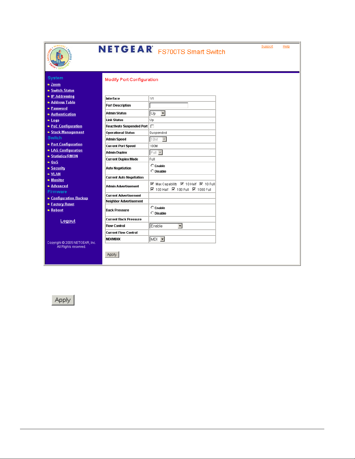
Figure 5 - 25: Modify Port Configuration Page
In addition to the fields in the Interface Configuration Page, the Modify Port Configuration Page includes the Reactivate Suspended Port field.
3. Define the fields.
4. Click
. The parameters are saved and the device is updated.
Defining LAG Members
Link Aggregation optimizes port usage by linking a group of ports together to form a single LAG. Aggregating ports multiplies the bandwidth
between the devices, increases port flexibility, and provides link redundancy. Ports added to a LAG lose their individual port configuration. When
ports are removed from the LAG, the original port configuration is applied to the ports. Ensure the following when configuring LAGs:
• All ports within a LAG must be the same media type.
• A VLAN is not configured on the port.
• The port is not assigned to a different LAG.
• Auto-negotiation mode is not configured on the port.
• The port is in full-duplex mode.
• All ports in the LAG have the same ingress filtering and tagged modes.
• All ports in the LAG have the same back pressure and flow control modes.
• All ports in the LAG have the same priority.
• All ports in the LAG have the same transceiver type.
Page 57
Page 58

• The device supports up to eight LAGs with eight ports in each LAG.
This section includes the following sections:
• Aggregating Ports
• Defining LAG Membership
Aggregating Ports
The LAG Settings Page contains fields for configuring parameters for configured LAGs. The system supports 8 LAGs, and each LAG can contain
up to 8 ports.
To define LAG parameters:
1. Click LAG Configuration- > LAG Settings. The LAG Settings Page opens.
Figure 5 - 26: LAG Settings Page
The LAG Settings Page contains the following fields:
• Interface — Displays the LAG number.
• LAG Description — Displays the user-defined port name.
• Link Status — Displays the link operational status. The possible field values are:
– UP — Indicates the LAG is currently linked and forwarding traffic.
– Down — Indicates the LAG is currently not linked.
• LAG Speed — Displays the configured rate for the LAG. The port type determines what speed setting options are available. LAG speeds can
only be configured when auto negotiation is disabled. The possible field values are:
– 10 — Indicates the LAG is currently operating at 10 Mbps.
Page 58
Page 59

– 100 — Indicates the LAG is currently operating at 100 Mbps.
– 1000 — Indicates the LAG is currently operating at 1000 Mbps.
• Auto Negotiation — Displays the auto negotiation status on the LAG. Auto negotiation is a protocol between two link partners that enables a
port to advertise its transmission rate, duplex mode, and flow control abilities to its partner.
• Flow Control — Displays the flow control status on the LAG. Operates when the port is in full duplex mode. Enabled by default.
2. Click a LAG. The Modify LAG Settings Page opens:
Figure 5 - 27: Modify LAG Settings Page
In addition to the fields in the LAG Settings Page, the Modify LAG Settings Page contains the following additional fields:
• Current Auto Negotiation — The current Auto Negotiation setting. Auto negation of Flow Control (FC) is enabled by default.
• Admin Adverti s e m e nt — Defines the auto-negotiation setting the port advertises. The possible field values are:
– Max Capability — Indicates that all port speeds and Duplex mode settings are accepted.
– 10 Half — Indicates that the port advertises for a 10 mbps speed port and half duplex mode setting.
– 10 Full — Indicates that the port advertises for a 10 mbps speed port and full duplex mode setting.
– 100 Half — Indicates that the port advertises for a 100 mbps speed port and half duplex mode setting.
– 100 Full — Indicates that the port advertises for a 100 mbps speed port and full duplex mode setting.
– 1000 Full — Indicates that the port advertises for a 1000 mbps speed port and full duplex mode setting.
• Current Advertisement — The port advertises its speed to its neighbor port to start the negotiation process. The possible field values are
those specified in the Admin Advertisement field.
Page 59
Page 60

• Neighbor Advertisement — Indicates the neighboring port’s advertisement settings. The field values are identical to the Admin
Advertisement field values.
3. Define the Port and LACP fields.
4. Click
. The LAG membership settings are saved and the device is updated.
Defining LAG Membership
The LAG Membership Page allows network managers to assign ports LAGs.
To assign ports to LAGs:
1. Click LAG Configuration > LAG Membership. The LAG Membership Page opens.
Figure 5 - 28: LAG Membership Page
The LAG Membership Page contains the following fields:
• LAG Port — Displays the LAG number.
• Link State — Displays the LAG operational status. The possible field values are:
– Link Present — Indicates the LAG is currently linked and forwarding traffic.
– Link Not Present — Indicates the LAG is currently not linked.
• Member — Displays the ports that are attached to the LAG.
• Delete — Removes the selected LAG.
– Checked — Removes the selected LAG.
– Unchecked — Maintains the LAGs.
Page 60
Page 61

2. Click a LAG. The Modify LAG Membership Page opens:
Figure 5 - 29: Modify LAG Membership Page
3. Select a port to attach to the selected LAG.
4. Click
. The LAG is defined and the device is updated.
Page 61
Page 62

Configuring VLANs
VLANs are logical subgroups within a Local Area Network (LAN), which combine user stations, and network devices into a single unit, regardless of
the physical LAN segment to which they are attached. VLANs allow network traffic to flow more efficiently within subgroups. VLANs use software to
reduce the amount of time it takes for network changes, additions, and moves to be implemented.
VLANs have no minimum number of ports, and can be created per unit, per device, or through any other logical connection combination since they
are software-based and not defined by physical attributes.
VLANs function at Layer 2. Since VLANs isolate traffic within the VLAN, a Layer 3 router working at a protocol level is required to allow traffic flow
between VLANs. Layer 3 routers identify segments and coordinate with VLANs. VLANs are Broadcast and Multicast domains. Broadcast and
Multicast traffic is transmitted only in the VLAN in which the traffic is generated.
VLAN tagging provides a method of transferring VLAN information between VLAN groups. VLAN tagging attaches a 4-byte tag to packet headers.
The VLAN tag indicates to which VLAN the packets belong. VLAN tags are attached to the VLAN by either the end station or the network device.
VLAN tags also contain VLAN network priority information.
The NETGEAR FS700TS-series Switch supports up to 128 active VLANs.
This section contains the following topics:
• Defining VLAN Properties
• Defining VLAN PVID Settings
Defining VLAN Properties
The VLAN Properties Page provides information and global parameters for configuring and working with VLANs.
To define VLAN properties:
1. Click Switch > VLAN. The VLAN Properties Page opens.
Figure 5 - 30: VLAN Properties Page
Page 62
Page 63

The VLAN Properties Page contains the following fields:
• ID — Displays the VLAN ID.
• Name — Displays the user-defined VLAN name.
• Type— Displays the VLAN type. The possible field values are:
– Static — Indicates the VLAN is user-defined.
– Default — Indicates the VLAN is the default VLAN. The default VLAN is enabled by default.
• Authentication — Indicates whether unauthorized users can access a Guest VLAN. The possible field values are:
– Enable — Enables unauthorized users to use the Guest VLAN.
– Disable — Disables unauthorized users from using the Guest VLAN.
• Delete— Removes VLANs. The possible field values are:
– Checked — Removes the selected VLAN.
– Unchecked — Maintains VLANs.
2. Select and click a VLAN in the ID field. The Add 802.1q VLAN Page opens:
3. Define the VLAN ID and VLAN Name fields.
4. Click
. The VLAN ID is defined and the device is updated.
Figure 5 - 31: Add 802.1q VLAN Page
Page 63
Page 64

Defining VLAN Membership
The VLAN Membership Page contains a table that maps VLAN parameters to ports. Ports are assigned VLAN membership by toggling through the
Port Control settings.
To define VLAN membership:
1. Click Basic Setup > VLAN > Membership > Membership. The VLAN Membership Page opens.
Figure 5 - 32: VLAN Membership Page
The VLAN Membership Page contains the following fields:
• VLAN ID — Displays the user-defined VLAN ID.
• VLAN Name — Displays the name of the VLAN.
• VLAN Type— Indicates the VLAN type. The possible field values are:
– Static — Indicates the VLAN is user-defined.
– Default — Indicates the VLAN is the default VLAN. The default VLAN is enabled.
• Port — Indicates the port membership.
• LAG — Indicates the LAG membership.
• Untagged — Indicates the interface is an untagged VLAN member. Packets forwarded by the interface are untagged.
• Tagged — Indicates the interface is a tagged member of a VLAN. All packets forwarded by the interface are tagged. The packets contain
VLAN information.
Page 64
Page 65

• Include — Includes the port in the VLAN.
• Exclude — Excludes the interface from the VLAN.
• Forbidden — Denies the interface VLAN membership.
2. Define the fields.
3. Click
. The VLAN Membership is defined and the device is updated.
Defining VLAN PVID Settings
The Interface PVID Settings Page contains parameters for assigning Port VLAN ID (PVID) values to interfaces. All ports must have a defined PVID.
If no other value is configured the default VLAN PVID is used. VLAN number 1 is the default VLAN and cannot be deleted from the system.
To open the Interface PVID Settings Page:
1. Click Switch > VLAN > Interface PVID Settings. The Interface PVID Settings Page opens:
Figure 5 - 33: Interface PVID Settings Page
The Interface PVID Settings Page contains the following fields:
• Unit No. — Displays the stacking member for which the PVID information is displayed.
• Interface — Displays the interface to which the PVID tag is assigned. The possible field values are:
– Port —Displays the port to which the PVID tag is attached.
– LAG— Displays the LAG to which the PVID tag is attached.
• PVID — Displays the PVID value. The possible field range is 1-4094.
Page 65
Page 66

2. Define the fields.
3. Click
. The PVID settings are saved and the device is updated.
Page 66
Page 67

Defining IP Addresses
This section contains the following topics:
• Configuring IP Interfaces
• Configuring ARP
Configuring IP Interfaces
The IP Interface Page contains fields for assigning IP addresses. IP addresses are either defined as static or are retrieved using the Dynamic Host
Configuration Protocol (DHCP). The IP Interface Page also contains information for defining default gateways DHCP is also configured from the IP
Interface Page. The assigns dynamic IP addresses to devices on a network. DHCP ensures that network devices can have a different IP address
every time the device connects to the network.
Note the following when configuring IP Addresses:
• If the device was accessed using the Smart Wizard Discovery Utility, the IP address retrieved through DHCP is displayed.
• If the device fails to retrieve an IP address through DHCP, the default IP address is 192.168.0.239.
To define an IP interface:
1. Click IP Addressing > IP Interface. The IP Interface Page opens:
Figure 5 - 34: IP Interface Page
The IP Interface Page contains the following fields:
• Get Dynamic IP from DHCP Server — Retrieves the IP addresses using DHCP.
• Static IP Address— Displays the currently configured IP address. IP addresses are either configured on the Default VLAN or are user-
defined.
Page 67
Page 68

• IP Address —Defines the interface used to manage the device.
• Subnet mask — Displays the currently configured IP address mask.
• Gateway — Defines the default gateway IP address.
2. Define the fields.
3. Click
. The IP configuration fields are saved and the device is updated.
Configuring ARP
The Address Resolution Protocol (ARP) converts IP addresses into physical addresses, and maps the IP address to a MAC address. ARP allows a
host to communicate with other hosts only when the IP address of its neighbors is known. To define ARP information:
1. Click IP Addressing > ARP. The
ARP Page opens:
Figure 5 - 35: ARP Page
The ARP Page contains the following fields:
• ARP Entry Age Out — Specifies the amount of time (in seconds) that passes between ARP Table entry requests. Following the ARP Entry
Age period, the entry is deleted from the table. The range is 1 - 40000000. The default value is 60000 seconds.
• Clear ARP Table Entries — Specifies the types of ARP entries that are cleared. The possible values are:
– None — Maintains the ARP entries.
– All — Clears all ARP entries.
– Dynamic — Clears only dynamic ARP entries.
– Static — Clears only static ARP entries.
• ID — Displays the ARP Table entry number.
Page 68
Page 69
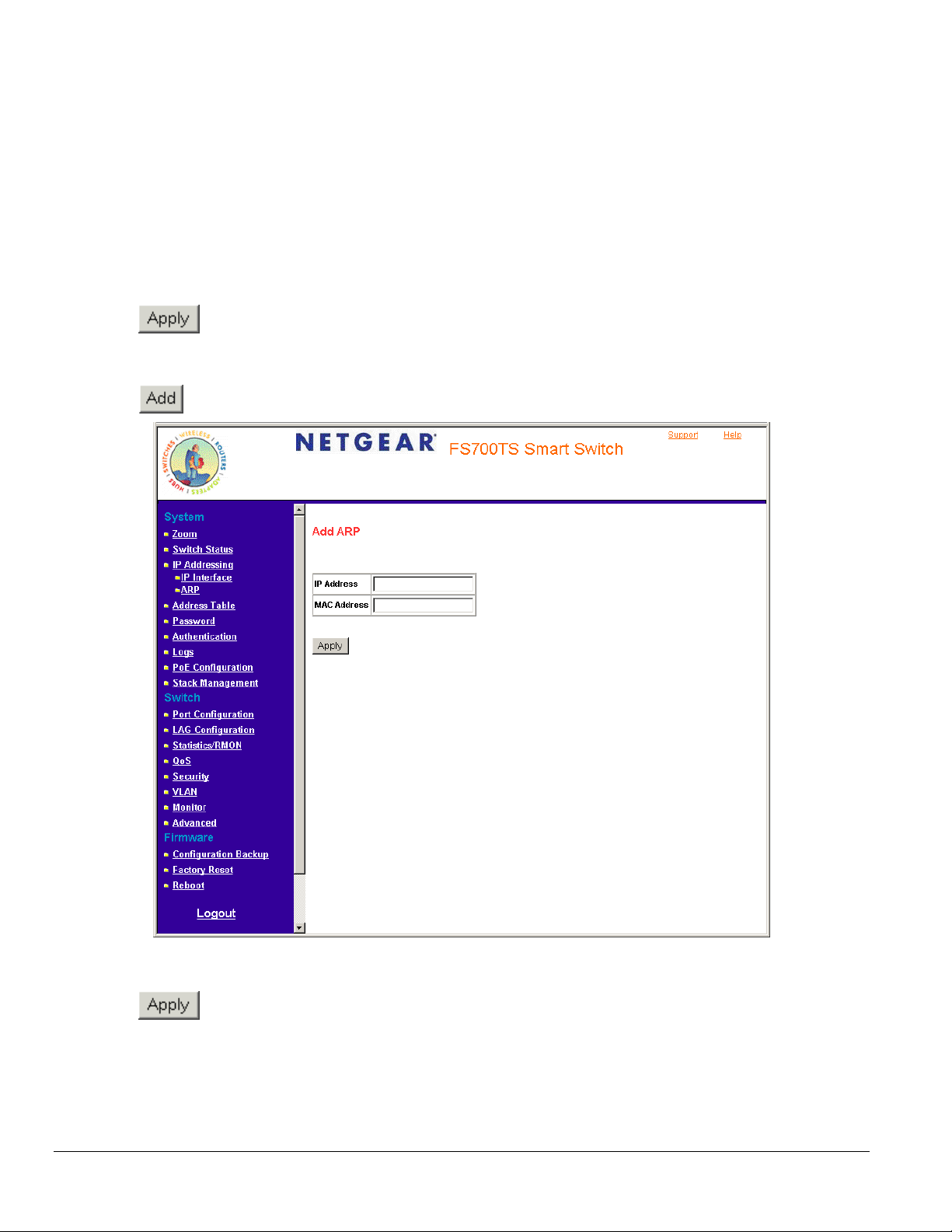
• IP Address — Indicates the station IP address, which is associated with the MAC address filled in below.
• MAC Address — Displays the station MAC address that is associated in the ARP table with the IP address.
• Status — Displays the ARP table entry type. Possible field values are:
– Dynamic — Indicates the ARP entry is learned dynamically.
– Static — Indicates the ARP entry is a static entry.
• Delete — Removes a specific ARP entry. The possible field values are:
– Checked — Removes the selected ARP entries.
– Unchecked — Maintains the current ARP entries.
2. Define the fields.
3. Click
To create a new ARP entry:
1. Click IP Addressing > ARP. The ARP Page opens.
2. Click
. The ARP parameters are defined and the device is updated.
. The Add ARP Page opens:
3. Define the fields.
4. Click
Figure 5 - 36: Add ARP Page
. The ARP interface is added and the device is updated.
Page 69
Page 70

Defining the Forwarding Address Tables
Packets addressed to destinations stored in either the Static or Dynamic databases are immediately forwarded to the port. The Dynamic MAC
Address Table can be sorted by interface, VLAN, or MAC Address, whereas MAC addresses are dynamically learned as packets from sources that
arrive at the device. Static addresses are configured manually.
An address becomes associated with a port by learning the port from the frame’s source address but if a frame that is addressed to a destination
MAC address is not associated with a port, that frame is flooded to all relevant VLAN ports. To prevent the bridging table from overflowing, a
dynamic MAC address, from which no traffic arrives for a set period, is erased.
The Defining the Forwarding Address Tables Page contains parameters for defining the age interval on the device. To prevent static MAC
addresses from being deleted when the device is reset, ensure that the port attached to the MAC address is locked. This section includes the
following topics:
• Configuring Static Addresses
• Defining Dynamic Addresses
Configuring Static Addresses
To configure the static addresses:
1. Click Address Table > Static Addresses. The Static Addresses Page opens.
Figure 5 - 37: Static Addresses Page
The Static Addresses Page contains the following fields:
• ID — Indicates the stacking number.
• VLAN ID — Displays the VLAN ID number to which the entry refers.
• MAC Address — Displays the MAC address to which the entry refers.
Page 70
Page 71

• Interface — Displays the interface to which the entry refers:
• Status — Displays how the entry was created. The possible field values are:
– Secure — The MAC Address is defined for locked ports.
– Permanent — The MAC address is permanent.
– Delete on Reset — The MAC address is deleted when the device is reset.
– Delete on Timeout — The MAC address is deleted when a timeout occurs.
• Delete — Removes the entry. The possible field values are:
– Checked — Removes the selected entry.
– Unchecked — Maintains the current static forwarding database.
To prevent static MAC addresses from being deleted when the device is reset, ensure the port attached to the MAC address is locked.
To add a new static address entry:
1. Click Address Table > Static Addresses. The Static Addresses Page opens.
2. Click
. The Add Static Addresses Page opens:
3. Define the fields.
4. Click
. The forwarding database information is modified and the device is updated.
Defining Dynamic Addresses
Figure 5 - 38: Add Static Addresses Page
Page 71
Page 72

The Dynamic Addresses Page contains parameters for querying information in the Dynamic MAC Address Table, including the interface type, MAC
addresses, VLAN, and table storing. The Dynamic MAC Address table contains information about the aging time before a dynamic MAC address is
erased and includes parameters for querying and viewing the Dynamic MAC Address table. The Dynamic MAC Address table contains address
parameters by which packets are directly forwarded to the ports. Interface, VLAN, and MAC Address can sort the Dynamic Address Table.
To configure the Dynamic MAC Address Table:
1. Click Address Table > Dynamic Addresses. The Dynamic Addresses Page opens.
Figure 5 - 39: Dynamic Addresses Page
The Dynamic Addresses Page contains the following fields:
• Address Aging — Specifies the amount of time the MAC address remains in the Dynamic MAC Address table before it is timed out if no
traffic from the source is detected. The default value is 300 seconds.
• Clear Table — To empty the current values from the table.
• Port — Specifies the interface for which the table is queried. There are two interface types from which to select.
• MAC Address — Specifies the MAC address for which the table is queried.
• VLAN ID — Specifies the VLAN ID for which the table is queried.
• Address Table Sort Key —Specifies the means by which the Dynamic MAC Address Table is sorted. The address table can be sorted by
address, VLAN, or interface.
• VLAN ID — Shows the ID of the current VLAN
• MAC — Displays the current MAC address.
• Port — Indicates the interface for which the table is currently queried
2. Define the fields.
3. Click
. The Dynamic Address Aging field is defined and the device is updated.
Page 72
Page 73

To query the Dynamic MAC Address Table:
1. Click Address Table > Dynamic Addresses. The Dynamic Addresses Page opens.
2. Select a port, MAC Address, and VLAN ID.
3. Select an Address Table Sort Key.
4. Click
. The Dynamic MAC Address Table is queried and the results are displayed.
Page 73
Page 74

Configuring the Spanning Tree Protocol
Spanning Tree Protocol (STP) provides tree topography for any arrangement of bridges. STP also provides a single path between end stations on
a network, eliminating loops. Loops occur when alternate routes exist between hosts. Loops in an extended network can cause bridges to forward
traffic indefinitely, resulting in increased traffic and reducing network efficiency.
To configure STP on the device:
1. Click Advanced Setup > Spanning Tree. The Spanning Tree Page opens:
Figure 5 - 40: Spanning Tree Page
The Spanning Tree Page contains the following fields:
• Spanning Tree State — Indicates whether STP is enabled on the device. The possible field values are:
– Enable — Enables STP on the device.
– Disable — Disables STP on the device.
Page 74
Page 75

• Hello Time (1-10) — Specifies the device Hello Time. The Hello Time indicates the amount of time in seconds a Root The device waits
between configuration messages. The default is 2 seconds.
• Max Age (6-40) — Specifies the device Maximum Age Time. The Maximum Age Time is the amount of time in seconds a bridge waits before
sending configuration messages. The default Maximum Age Time is 20 seconds.
• Forward Delay (4-30) — Specifies the device Forward Delay Time. The Forward Delay Time is the amount of time in seconds a bridge
remains in a listening and learning state before forwarding packets. The default is 15 seconds.
• Unit Number — Indicates the stacking member for which the STP information is displayed.
• Interface — Indicates the port or LAG for which the STP information is displayed.
• Fast Link — Indicates if Fast Link is enabled on the port. If Fast Link mode is enabled for a port, the Port State is automatically placed in the
Forwarding state when the port link is up. Fast Link optimizes the STP protocol convergence. STP convergence can take 30-60 seconds in
large networks. The possible field values are:
– Enable — Indicates that Fast Link is enabled on the port.
– Disable — Indicates that Fast Link is disabled on the port.
• Port State — Displays the current STP state of a port. If enabled, the port state determines what forwarding action is taken on traffic. Possible
port states are:
– Forwarding — Indicates that STP is enabled on the port, and the port is forwarding packets based on the STP topology.
– Disabled — Indicates that STP is currently disabled on the port. The port forwards traffic while learning MAC addresses.
– Blocking — Indicates that the port is currently blocked and cannot forward traffic or learn MAC addresses. Blocking is displayed when
STP is enabled.
• Speed — Indicates the speed at which the port is operating.
• Path Cost — Specifies the method used to assign default path cost to STP ports. The possible field values are:
– Short — Specifies 1 through 65,535 range for port path cost. This is the default value.
– Long — Specifies 1 through 200,000,000 range for port path cost. The default path cost assigned to an interface varies according to the
selected method (Hello Time, Max Age, or Forward Delay).
• Priority — Specifies the bridge priority value. When switches or bridges are running STP, each is assigned a priority. After exchanging
BPDUs, the device with the lowest priority value becomes the Root Bridge. The default value is 32768. The port priority value is provided in
increments of 4096.
• BPDU Handling — Determines how BPDU packets are managed when STP is disabled on the port or device. BPDUs are used to transmit
spanning tree information. The possible field values are:
– Filtering — Filters BPDU packets when spanning tree is disabled on an interface. This is the default value.
– Flooding — Floods BPDU packets when spanning tree is disabled on an interface.
• Priority (0-65535) — Reflects the value entered in the Priority field above.
2. Select Enable in the Spanning Tree State field.
3. Select an STP type in the STP Operation Mode field.
4. Define the BPDU Handling and Path Cost Default Values fields.
5. Select either the Hello Time, Max Age, or Forward Delay field.
6. Click
. STP is enabled and the device is updated.
Page 75
Page 76

Defining STP on Interfaces
Network administrators can assign STP settings to specific interfaces using the Modify Spanning Tree Page. The Global LAGs section displays the
STP information for Link Aggregated Groups.
To assign STP settings to an interface:
1. Click Advanced > Spanning Tree and click an interface. The Modify Spanning Tree Page opens:
Figure 5 - 41: Modify Spanning Tree Page
The Modify Spanning Tree Page contains the following fields:
• Interface — The interface for which the information is displayed.
• STP— Indicates if STP is enabled on the port. The possible field values are:
– Enable — Enables STP on the port.
– Disable — Disables STP on the port. This is the default value.
• Fast Link — Indicates if Fast Link is enabled on the port. If Fast Link mode is enabled for a port, the Port State is automatically placed in the
Forwarding state when the port link is up. Fast Link optimizes the STP protocol convergence. STP convergence can take 30-60 seconds in
large networks.
• Port State — Displays the current STP state of a port. If enabled, the port state determines what forwarding action is taken on traffic. Possible
port states are:
– Disabled — Indicates that STP is currently disabled on the port. The port forwards traffic while learning MAC addresses.
– Blocking — Indicates that the port is currently blocked and cannot forward traffic or learn MAC addresses. Blocking is displayed when
STP is enabled.
Page 76
Page 77

• Role — Displays the port role assigned by the STP algorithm to provide to STP paths. The possible field values are:
– Designated — The port or LAG through which the designated switch is attached to the LAN.
– Alternate — Provides an alternate path to the root switch from the root interface.
– Backup — Provides a backup path to the designated port path toward the Spanning Tree leaves. Backup ports occur only when two ports
are connected in a loop by a point-to-point link or when a LAN has two or more connections connected to a shared segment.
– Disabled — The port is not participating in the Spanning Tree.
• Speed — Indicates the speed at which the port is operating.
• Path Cost — Indicates the port contribution to the root path cost. The path cost is adjusted to a higher or lower value and is used to forward
traffic when a path is re-routed.
• Priority — Priority value of the port. The priority value influences the port choice when a bridge has two ports connected in a loop. The priority
value is between 0 -240. The priority value is determined in increments of 16.
2. Select Enable in the STP field.
3. Define the fields.
4. Click
. STP is enabled on the interface and the device is updated.
Page 77
Page 78

Configuring Quality of Service
Quality of Service (QoS) provides the ability to implement QoS and priority queuing within a network. For example, certain types of traffic that
require minimal delay, such as Voice, Video, and real-time traffic can be assigned a high priority queue, while other traffic can be assigned a lower
priority queue. The result is an improved traffic flow for traffic with high demand. QoS is defined by:
• Classification — Specifies which packet fields are matched to specific values. All packets matching the user-defined specifications are
classified together.
• Action — Defines traffic management where packet forwarding is based on packet information and packet field values such as VLAN Priority
Tag (VPT) and DiffServ Code Point (DSCP).
After packets are assigned to a specific egress queue, CoS services can be assigned to the queue. Egress queues are configured with a
scheduling scheme by one of the following methods:
• Strict Priority — Ensures that time-sensitive applications are always forwarded. Strict Priority (SP) allows the prioritization of mission-critical,
time-sensitive traffic over less time-sensitive applications.
For example, under SP, voice over IP (VoIP) traffic can be prioritized so that it is forwarded before FTP or email (SMTP) traffic.
• Weighted Round Robin — Ensures that a single application does not dominate the device forwarding capacity. Weighted Round Robin
(WRR) forwards entire queues in a round robin order. All queues can participate in WRR, except SP queues. If the traffic flow is minimal, and
SP queues do not occupy the whole bandwidth allocated to a port, the WRR queues can share the bandwidth with the SP queues. This
ensures that the remaining bandwidth is distributed according to the weight ratio. If WRR is selected, the following weights are assigned to the
queues: 1, 2, 4, 8.
This section contains information for defining general QoS settings, and includes the following topics:
• Defining General QoS Setting
• Defining QoS Queues
• Configuring Bandwidth Settings
Page 78
Page 79

Defining General QoS Settings
The CoS Page contains information for enabling QoS globally and on specific interfaces. After QoS has been configured, the original device QoS
default settings can be reassigned to the interface in the CoS Page.
To enable QoS:
1. Click QoS > General > CoS. The CoS Page opens:
Figure 5 - 42: CoS Page
The CoS Page contains the following:
• Unit No. — Displays the stacking member for which the QoS information is displayed.
• CoS Mode — Determines whether QoS is enabled on the device. The possible values are:
– Enable — Enables QoS on the interface.
Page 79
Page 80

– Disable — Disables QoS on the interface.
• Trust Mode — Defines which packet fields to use for classifying packets entering the device. When no rules are defined, the traffic containing
the predefined packet CoS field is mapped according to the relevant trust modes table. Traffic not containing a predefined packet field is
mapped to best effort. The possible Trust Mode field values are:
– CoS — Classifies traffic based on the CoS (VPT) tag value.
– DSCP — Classifies traffic based on the DSCP tag value.
– None — Indicates that Trust is not enabled on the device.
• Interface — Displays the interface for which the global QoS parameters are defined.
– Port — Selects the port for which the global QoS parameters are defined.
– LAG — Selects the LAG for which the global QoS parameters are defined.
• Default CoS for Incoming Traffic — Determines the default CoS value for incoming packets for which a VLAN tag is not defined.
The possible field values are 0-7. The default CoS value is 0.
2. Select Enable in the Quality of Service field.
3. Define the Trust Mode field.
4. Click
. Quality of Service is enabled on the device.
Page 80
Page 81

Defining QoS Queues
The Defining QoS Queues Page contains fields for defining the QoS queue forwarding types.
To set the queue settings:
1. Click QoS > General > Queue. The Queue Page opens.
Figure 5 - 43: Queue Page
The Queue Page contains the following fields:
• Strict Priority — Specifies whether traffic scheduling is based strictly on the queue priority.
• WRR — Assigns WRR weights to queues. This field is enabled only for queues in WRR queue mode.
2. Select Strict Priority or WRR Fields.
3. Click
. The queue settings are set and the device is updated.
Page 81
Page 82

Configuring Bandwidth Settings
After packets are assigned to a queue, a scheduling scheme can be assigned to an interface, using either:
• Committed Burst Size — Indicates the maximum number of data bits transmitted within a specific time interval.
• Committed Information Rate — Indicates the rate that data is transmitted. The rate is averaged over a minimum time increment.
The Bandwidth Page allows network managers to define the bandwidth settings for a specified egress interface. Modifying queue scheduling
affects the queue settings globally. Queue shaping can be based per queue and/or per interface. Shaping is determined by the lower specified
value. The queue shaping type is selected in the Bandwidth Page.
To define bandwidth settings:
1. Click QoS > General > Bandwidth. The Bandwidth Page opens:
Figure 5 - 44: Bandwidth Page
The Bandwidth Page contains the following fields:
• Interface — Indicates the stacking members for which the bandwidth settings are displayed.
• Status — Indicates if rate limiting is enabled on the interface. The possible field values are:
– Enable — Enables rate limiting on the interface.
– Disable — Disables rate limiting on the interface. This is the default value.
• Rate Limit — Displays the amount of bandwidth assigned to the interface.
• Delete — Deletes the bandwidth settings from the interface. The possible field values are:
Page 82
Page 83
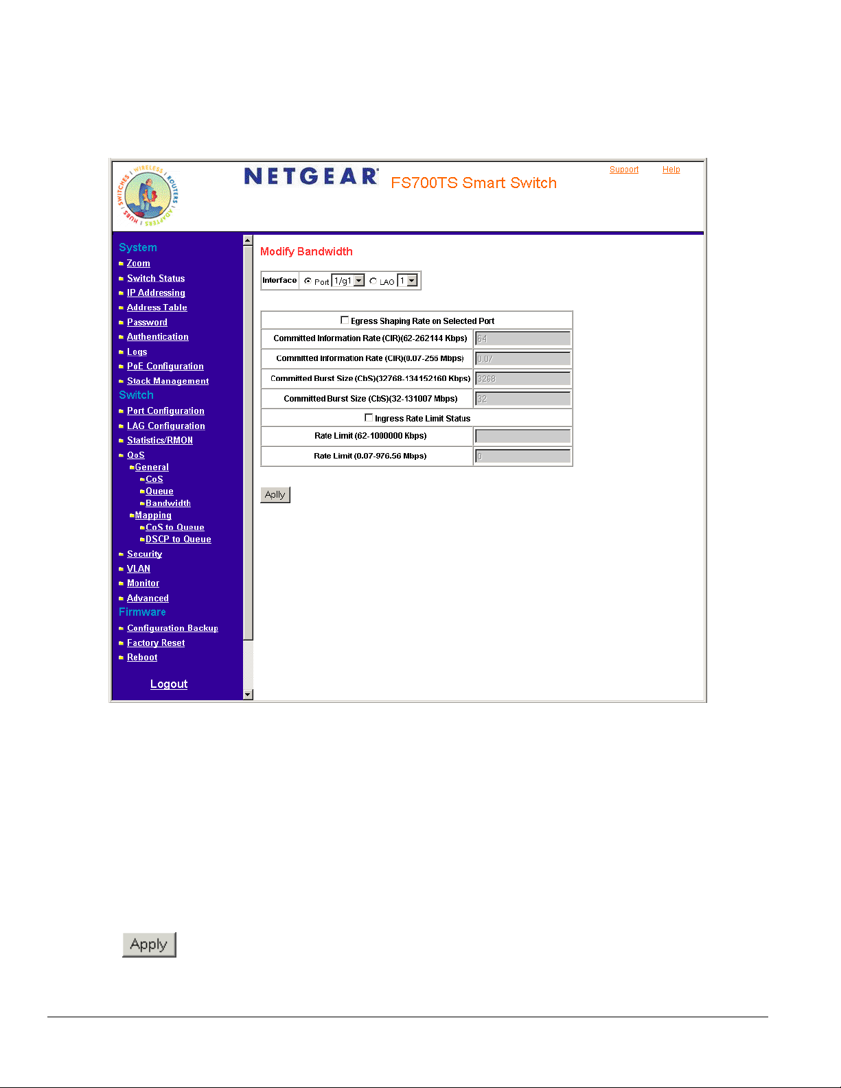
– Checked — Deletes the bandwidth settings from the selected interface.
– Unchecked — Maintains the bandwidth settings from the selected interface. This is the default value.
2. Click an interface. The Modify Bandwidth Page opens.
Figure 5 - 45: Modify Bandwidth Page
In addition to the fields in the Bandwidth Page the M additional fields:
• Egress Shaping Rate on Selected Port — Determines the egress port bandwidth settings for the selected in
values are:
– Commit
– tted Information Rate (CIR) (0.07-256 Mbps) — Defines the CIR in megabytes per seconds. The possible field range is 0.07 -256
ted Information Rate (CIR)(62-262144 Kbps) — Defines the CIR in kilobytes per seconds. The possible field range is 62 -262144
Kbps.
Commi
Mbps.
odify Bandwidth Page contains the following
terface. The possible field
• Ingress Rate Limit Status — Determines the ingress port bandwidth settings for the selected interface.
– Rate Limit (62-1000000 Kbps) — Defines the interface rate limiting to kilobytes per second. The field
– Rate Limit (0.07-976.56 Mbps) — Defines the interface rate limiting to Megabytes per second. The field range is 0.07-976.56 Mbp
3. Define the fields.
4. Click
. The bandwidth settings are saved to interface and the device is updated.
range is 62-1000000 Kbps.
Page 83
s.
Page 84

Mapping CoS Values to Queues
The CoS to Queue Page contains fields for mapping CoS values to traffic queues. To map CoS values to queues:
1. Click QoS > Mapping > CoS to Queue. The CoS to Queue Page opens.
Figure 5 - 46: CoS to Queue Page
The CoS to Queue Page contains the following fields:
• Class of Service — Specifies the CoS priority tag values, where zero is the lowest and 7 is the highest.
• Queue — Defines the traffic forwarding queue to which the CoS priority is mapped. Eight traffic priority queues are supported.
• Restore Defaults — Restores the device factory defaults for mapping CoS values to a forwarding queue.
2. Define the queue number in the Queue field next to the required CoS value.
3. Click
. The CoS value is mapped to a queue and the device is updated.
Page 84
Page 85

Mapping DSCP Values to Queues
The DSCP to Queue Page contains fields for mapping DSCP settings to traffic queues. For example, a packet with a DSCP tag value of 3 can be
assigned to queue 2.
To map CoS values to queues:
1. Click QoS > General > Mapping > DSCP to Queue. The DSCP to Queue Page opens.
Figure 5 - 47: DSCP to Queue Page
The DSCP to Queue Page contains the following fields:
• DSCP In — Displays the incoming packet’s DSCP value.
• Queue — Specifies the traffic-forwarding queue to which the DSCP priority is mapped. Four traffic priority queues are supported.
2. Define the queue number in the Queue field next to the required DSCP value.
3. Click
. The DSCP value is mapped to a queue and the device is updated.
Page 85
Page 86

Configuring SNMP Security
Simple Network Management Protocol (SNMP) provides a method for managing network devices. The device supports the following SNMP
versions:
• SNMP v1 and v2c
• SNMP version 3
The SNMP agents maintain a list of variables that are used to manage the device. The variables are defined in the Management Information Base
(MIB). The SNMP agent defines the MIB specification format, as well as the format used to access the information over the network. Access strings
control access rights to the SNMP agents.
SNMP v3 applies access control and a new traps mechanism. In addition, User Security Model (USM) parameters are defined for SNMPv3,
including:
• Authentication — Provides data integrity and data origin authentication.
• Privacy — Protects against the disclosure of message content. Cipher Block-Chaining (CBC) is used for encryption. Either
authentication is enabled on an SNMP message, or both authentication and privacy are enabled on an SNMP message. However,
privacy cannot be enabled without authentication.
• Timeliness — Protects against message delay or message redundancy. The SNMP agent compares the incoming message to the
message time information.
• Key Management — Defines key generation, key updates, and key use.
The device supports SNMP notification filters based on Object IDs (OIDs). OIDs are used by the system to manage device features.
SNMP v3 supports the following features:
• Security
• Feature Access Control
• Traps
The device generates copy traps.
This section contains the following topics:
• Defining SNMP Engine ID
• Defining SNMP Users
• Defining SNMP Views
• Defining SNMP Communities
• Trap Station Management
• Global Trap Settings
• Trap Filter Settings
Page 86
Page 87

Defining SNMP Engine ID
The Engine ID Page allows network managers to define the SNMP Engine ID and allows network managers to assign the default parameters to
SNMP.
To define the Local Engine ID:
1. Click Advanced > SNMP > Engine ID. The Engine ID Page opens:
Figure 5 - 48: Engine ID Page
The Engine ID Page contains the following fields:
• Local Engine ID (0-32 Characters) — Displays the local device Engine ID. The field value is a hexadecimal string. Each byte in hexadecimal
character strings is two hexadecimal digits. Each digit can be separated by a period or a colon. The Engine ID must be defined before
SNMPv3 is enabled.
• Use Default — Uses the device-generated Engine ID. The default Engine ID is based on the device MAC address and is defined per standard
as:
– First 4 octets — first bit = 1, the rest is IANA Enterprise number.
– Fifth octet — Set to 3 to indicate the MAC address that follows.
– Last 6 octets — MAC address of the device.
Page 87
Page 88

2. Define the Local Engine ID and Use Default fields.
3. Click
. The SNMP global security parameters are set and the device is updated.
Defining SNMP Users
The SNMP Users Page provides information for creating SNMP groups and assigning SNMP access control privileges to SNMP groups. Groups
allow network managers to assign access rights to specific device features or feature aspects. To define an SNMP group:
1. Click Advanced > SNMP > Users. The SNMP Users Page opens:
Figure 5 - 49: SNMP Users Page
The SNMP Users Page contains the following fields:
• ID – Displays the table entry number.
• User Name — Contains a list of user-defined user names. The field range is up to 30 alphanumeric characters.
• Group Name — Contains a list of user-defined SNMP groups. SNMP groups are defined in the SNMP Group Profile Page.
• Engine ID — Displays either the local or remote SNMP entity to which the user is connected. Changing or removing the local SNMP Engine
ID deletes the SNMPv3 user database.
– Local — Indicates that the user is connected to a local SNMP entity.
Page 88
Page 89

– Remote — Indicates that the user is connected to a remote SNMP entity. If the Engine ID is defined, remote devices receive inform
messages.
• Authentication — Displays the method used to authenticate users. The possible field values are:
– MD5 Key — Users are authenticated using the HMAC-MD5 algorithm.
– SHA Key — Users are authenticated using the HMAC-SHA-96 authentication level.
– MD5 Password — The HMAC-MD5-96 password is used for authentication. The user should enter a password.
– SHA Password — Users are authenticated using the HMAC-SHA-96 authentication level. The user should enter a password.
– No Authentication — No user authentication is used.
• Delete — Removes users from a specified group. The possible field values are:
– Checked — Removes the selected user.
– Unchecked — Maintains the list of users.
2. Click
. The Add SNMP Users Page opens:
3. Define the fields.
4. Click
Figure 5 - 50: Add SNMP Users Page
. The SNMP user is defined and the device is updated.
Page 89
Page 90

Defining SNMP Groups
The Groups Page provides information for creating SNMP groups and assigning SNMP access control privileges to SNMP groups. Groups allow
network managers to assign access rights to specific device features or feature aspects.
To define an SNMP group:
1. Click Advanced SNMP > Groups. The Groups Page opens:
Figure 5 - 51: Groups Page
The Groups Page contains the following fields:
• ID – Indicates the stacking number
• Group Name — Displays the user-defined group to which access control rules are applied. The field range is up to 30 characters.
• Security Model — Defines the SNMP version attached to the group. The possible field values are:
– SNMPv1 — SNMPv1 is defined for the group.
– SNMPv2c — SNMPv2c is defined for the group.
– SNMPv3 — SNMPv3 is defined for the group.
• Security Level — Defines the security level attached to the group. Security levels apply to SNMPv3 only. The possible field values are:
Page 90
Page 91

– No Authentication — Indicates that neither the Authentication nor the Privacy security levels are assigned to the group.
– Authentication — Authenticates SNMP messages and ensures that the SNMP message’s origin is authenticated.
– Privacy — Encrypts SNMP messages.
• Operation — Defines the group access rights. The possible field values are:
– Read — Management access is restricted to read-only. Changes cannot be made to the assigned SNMP view.
– Write — Management access is read-write. Changes can be made to the assigned SNMP view.
– Notify — Sends traps for the assigned SNMP view.
• Delete — Removes SNMP groups. The possible field values are:
– Checked — Removes the selected SNMP group.
– Unchecked — Maintains the SNMP groups.
2. Click . The Add Groups Page opens:
3. Define the fields.
4. Click
Figure 5 - 52: Add Groups Page
. The SNMP group profile is added and the device is updated.
Page 91
Page 92

To modify SNMP Group settings:
1. Click Advanced > SNMP > Groups. The Groups Page opens.
2. Click the ID of the group you want to modify. The Modify Groups Page opens:
3. Modify the fields.
4. Click
Figure 5 - 53: Modify Groups Page
. The SNMP group profile is modified and the device is updated.
Page 92
Page 93

Defining SNMP Views
SNMP Insert space views provide or block access to device features or portions of features. For example, a view can be defined which provides
that SNMP group A has Read Only (R/O) access to Multicast groups, while SNMP group B has Read-Write (R/W) access to Multicast groups.
Feature access is granted via the MIB name or MIB Object ID. To define SNMP views:
1. Advanced > SNMP > Views. The Views Page opens:
Figure 5 - 54: Views Page
The Views Page contains the following fields:
• View Name — Displays the user-defined views. The view name can contain a maximum of 30 alphanumeric characters.
• ID – Indicates the stacking number.
• Object ID Subtree — Displays the device feature OID included in or excluded from the selected SNMP view.
• View Type — Indicates whether the defined OID branch will be included in or excluded from the selected SNMP view.
• Delete — Deletes the currently selected view. The possible field values are:
– Checked — Removes the selected view.
– Unchecked — Maintains the list of views.
Page 93
Page 94

2. Click
. The Add Views Page opens:
3. Define the fields.
4. Click
Figure 5 - 55: Add Views Page
. The view is defined and the device is updated.
Page 94
Page 95

Defining SNMP Communities
Access rights are managed by defining communities in the SNMP Communities Page. When the community names are changed, access rights are
also changed. SNMP communities are defined only for SNMP v1 and SNMP v2c. To define SNMP communities:
1. Click Advanced > SNMP > Communities. The Communities Page opens:
Figure 5 - 56: Communities Page
The Communities Page is divided into the following tables:
• Basic Table
• Advanced Table
SNMP Communities Basic Table
The SNMP Communities Basic Table contains the following fields when using SNMPv1 and SNMPv3:
• ID — Indicates the table entry number.
• Management Station — Displays the management station IP address for which the basic SNMP community is defined.
• Community String — Defines the password used to authenticate the management station to the device.
• Access Mode — Defines the access rights of the community. The possible field values are:
Page 95
Page 96

– Read Only — Management access is restricted to read-only. Changes cannot be made to the community.
– Read Write — Management access is read-write. Changes can be made to the device configuration but not to the community.
– SNMP Admin — User has access to all device configuration options, as well as permissions to modify the community.
• View Name — Contains a list of user-defined SNMP views.
• Delete — Removes a community. The possible field values are:
– Checked — Removes the selected SNMP community.
– Unchecked — Maintains the SNMP communities.
SNMP Communities Advanced Table
The SNMP Communities Advanced Table contains the following fields:
• ID — Indicates the table entry number.
• Management Station — Displays the management station IP address for which the advanced SNMP community is defined.
• Community String — Defines the password used to authenticate the management station to the device.
• Group Name — Defines advanced SNMP community group names.
• Delete — Removes a community. The possible field values are:
– Checked — Removes the selected SNMP communities.
– Unchecked — Maintains the SNMP communities.
2. Click
. The Add Communities Page opens:
Page 96
Page 97

Figure 5 - 57: Add Communities Page
3. Define the OOB Management Stations, SNMP Management Station, Community String, and Basic or Advanced tables.
4. Click
To modify SNMP community settings:
1. Click Advanced > SNMP > Communities. The Communities Page opens.
2. Click an ID. The Modify Communities Page opens:
. The SNMP community is added and the device is updated.
Page 97
Page 98

Figure 5 - 58: Modify Communities Page
3. Modify the SNMP Management Station, Community String, and Basic or Advanced tables.
4. Click
. The SNMP community is modified and the device is updated.
Page 98
Page 99

Trap Station Management
The Trap Station Management Page contains information for defining filters that determine whether traps are sent to specific users, and the trap
type sent. SNMP notification filters provide the following services:
• Identifying Management Trap Targets
• Trap Filtering
• Selecting Trap Generation Parameters
• Providing Access Control Checks
To define trap station management:
1. Click Advanced > SNMP > Trap Station Management. The Trap Station Management Page opens:
Figure 5 - 59: Trap Station Management Page
The Trap Station Management Page is divided into the following tables:
• SNMPv1, 2 Notification Recipient
• SNMPv3 Notification Recipient
Page 99
Page 100

SNMPv1, 2c Notification Recipient
The SNMP v1, v2c Recipient table contains the following fields:
• ID — Indicates the stacking number.
• Recipients IP — Displays the IP address to which the traps are sent.
• Notification Type — Displays the notification sent. The possible field values are:
– Trap — Indicates traps are sent.
– Inform — Indicates informs are sent.
• Community String — Displays the community string of the trap manager.
• Notification Version — Displays the trap type. The possible field values are:
– SNMP V1 — Indicates that SNMP Version 1 traps are sent.
– SNMP V2c — Indicates that SNMP Version 2 traps are sent.
• UDP Port — Displays the UDP port used to send notifications. The default is 162.
• Filter Name — Indicates if the SNMP filter for which the SNMP Notification filter is defined.
• Timeout — Indicates the amount of time (in seconds) the device waits before re-sending informs. The default is 15 seconds.
• Retries — Indicates the amount of times the device re-sends an inform request. The default is 3 seconds.
• Delete — Removes the currently selected recipient. The possible field values are:
– Checked — Removes the selected recipient from the list of recipients.
– Unchecked — Maintains the list of recipients.
SNMPv3 Notification Recipient
The SNMPv3 Notification Recipient table contains the following fields:
• ID — Indicates the stacking number.
• Recipient IP — Displays the IP address to which the traps are sent.
• Notification Type — Displays the type of notification sent. The possible field values are:
– Trap — Indicates that traps are sent.
– Inform — Indicates that informs are sent.
• User Name — Displays the user to which SNMP notifications are sent.
• Security Level — Displays the means by which the packet is authenticated. The possible field values are:
– No Authentication — Indicates that the packet is neither authenticated nor encrypted.
– Authentication — Indicates that the packet is authenticated.
• UDP Port — The UDP port used to send notifications. The field range is 1-65535. The default is 162.
• Filter Name — Includes or excludes SNMP filters.
• Timeout — The amount of time (seconds) the device waits before resending informs. The field range is 1-300. The default is 10 seconds.
• Retries — The amount of times the device resends an inform request. The field range is 1-255. The default is 3.
• Delete — Removes the currently selected recipient. The possible field values are:
– Checked — Removes the selected recipient from the list of recipients.
– Unchecked — Maintains the list of recipients.
2. Click
. The Add Trap Station Management Page opens.
Page 100
 Loading...