

Page 1

GS700TS FS700TS – Access to the Internet on multiple VLANS using MultiHoming
This document describes how to obtain Internet access on multiple VLANs using one Internet
gateway capable of managing multiple IP subnets (Multi-homing).
The procedure described can apply to all the Smart Switches and VPN Firewall with new Web
Interface (defined as the one with the Menus appearing horizontally on top).
Table of Contents
VLAN-Definition ........................................................................................................................... 2
Notes when setting-up VLANs ..................................................................................................... 2
Multi-Homing (extract from the DGFV338 Help page) .................................................................. 3
Physical Setup ............................................................................................................................ 3
Logical Setup .............................................................................................................................. 3
DGFV338 Primary LAN ............................................................................................................... 4
DGFV338 Secondary VLAN ........................................................................................................ 5
Smartswitch VLAN creation ......................................................................................................... 6
Assigning Port membership to a VLAN ........................................................................................ 7
Assigning a PVID to a port ........................................................................................................... 8
Testing the scenario .................................................................................................................. 10
Further notes ............................................................................................................................. 10
Page 2
VLAN-Definition
VLANs are logical subgroups within a Local Area Network (LAN), which combine user stations,
and network devices into a single unit, regardless of the physical LAN segment to which they are
attached. VLANs allow network traffic to flow more efficiently within subgroups. VLANs use
software to reduce the amount of time it takes for network changes, additions, and moves to be
implemented.
Notes when setting-up VLANs
• A VLAN does not have a minimum number of port
• VLANs work at the OSI Layer 2
• A VLAN can be created per unit, device or via logical connection/combination
• Broadcast and Multicast traffic is transmitted only in the VLAN in which traffic is generated.
• To allow traffic between VLAN a device working at protocol level (Layer 3) is required
24 Port 10/100/1000 Mbps Smart Switch
2143658710912111413161518172019222124
Reset PWR
LINK/ACT
23
Green = 100Mbps
SPD
Yellow = 10Mbps
FDX
LINK/ACT
SPD
FDX
1 3 5 7 9 11 13 15 17 19 21 23T
2 4 6 8 10 12 14 16 18 20 22 24T
MODEL
ProSafe VPN Wireless ADSL Gateway
INTERNET
PWR
TEST
100
1 2 3 4 5 6 7 8
WLANDSL
DGFV338
LOCAL
100
Link/ACTLINK/ACT
SFP
LINK
23F 24F
SFP
LINK
MODEL
GS724T
Auto
Uplink
Factory
Defaults
Page 3

Multi-Homing (extract from the DGFV338 Help page)
Secondary LAN IP Setup
Availa
ble Secondary LAN IPs
Subnet Mask:
Action/Edit:
Select All:
Available Secondary LAN IPs
Add Secondary LAN IP Address
addresses, gateway IP and DNS server IPs.
Example:
Ne t w or k C on fi g u r a t io n
If you have computers using different IP networks in the LAN, (for example:
172.16.2.0, 10.0.0.0), then you can add “aliases” to the LAN port and give
computers on those networks, access to the Internet.
The tables lists the secondary LAN IP addresses added to the router.
IP Address: The IP address alias added to the LAN port of the router. This is the
gateway for computers that need to access the Internet.
IPv4 Subnet Mask.
Click to make changes to the selected entry.
Selects all the entries in the
Delete: Deletes selected entries from the Available Secondary LAN IPs table.
To add a secondary LAN IP address, type in the IP Address and the Subnet
Mask in the respective text fields and click Add.
Note: Additional IP addresses cannot be configured in the DHCP server. The
hosts on the secondary subnets must be manually configured with the IP
IMPORTANT!
Make sure the secondary IP addresses are different from the LAN, WAN, and
any other subnet attached to this router.
ADSL IP address: 10.0.0.1 with subnet 255.0.0.0
WAN Ethernet IP address: 20.0.0.1 with subnet 255.0.0.0
LAN IP address: 192.168.1.1 with subnet 255.255.255.0
Secondary LAN IP: 192.168.20.1 with subnet 255.255.255.0
table.
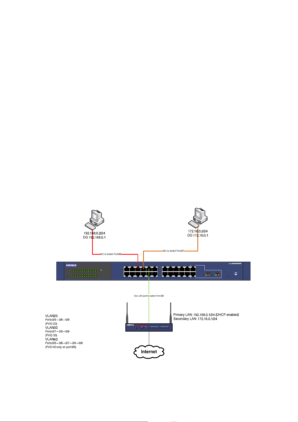
Physical Setup
1x GS724TS Prosafe Smartswitch - Firmware 3.1.0.1
2x Windows XP Computers (2 on each VLAN)
1 x DGFV338 Prosafe Firewall Router (Router firmware 3.4.0.19)
Logical Setup
GS724TS:
Management IP on VLAN1 (192.168.0.239)
DGFV338 :
Primary range 192.168.0.1/24 (DHCP enabled)
Seconday range 172.16.0.1/24 (DHCP not enabled)
PC1 – VLAN20 – 192.168.0.2/24
PC2 – VLAN30 – 172.16.0.2/24
VLAN20: Ports 0/5 and 0/6 and 0/9 (PVID 20 for all the ports)
VLAN30: Ports 0/7 and 0/8 and 0/9 (PVID 30 for all the ports)
VLAN40: Port 0/5 – 0/9 (PVID 40 only for port 0/9)
Page 4

DGFV338 Primary LAN
The Primary LAN settings can be defined on the GUI of the DGFV338 (Network Configuration,
LAN Setup).
If DHCP is required ensure that the correct Starting IP address and Ending IP address are
configured including the DNSs settings.
Page 5

DGFV338 Secondary VLAN
In order to add a Secondary LAN to the DGFV338 the Multi-homing option should be used.
This can be accessed via the GUI (Network configuration, LAN Setup, Multi-Homing)
PCs with an IP address within this range will need the IP address, Default Gateway and DNS
servers (if different from the Default Gateway) manually set.
Page 6

Smartswitch VLAN creation
VLAN are created on the Smartswitch via the GUI (Switching, VLAN, Basic, VLAN configuration).
To complete the scenarion 3 VLAN will need to be created.
The two pictures below show the creation of VLAN20, and the results of the creation of all the
VLAN required to complete the scenario (VLAN20, 30, 40)
Page 7

Assigning Port membership to a VLAN
Port membership can be assigned via the GUI (Switching, VLAN, Advanced , VLAN
membership).
Three options are available:
- No membership (no simbol appearing in the gray box underneath the port number)
- Untagged membership (U)
- Tagged membership (T)
In order to browse through the options just continuosly click on the gray box until the correct one
is set.
For this scenarion we will be using the U (Untagged) option on all the ports.
Page 8

Assigning a PVID to a port
The PVID (Port VLAN ID) is assigned to each port via the GUI (Switching, VLAN, Advanced, Port
PVID configuration).
It is important that the PVID matches the VLAN a port is member of, unless such port belongs to
multiple VLANs (in which case the PVID must still be set and be unique, but can match any of the
VLAN IDs).
In our scenario the following PVID will apply:
Ports 0/5 - 0/6 (PVID 20)
Ports 0/7 - 0/8 (PVID 30)
Port 0/9 (PVID 40)
The below pictures show how after clicking on apply (for all 3 VLANs PVID) we obtain the correct
settings:
Page 9

Page 10

Testing the scenario
In order to test the scenario:
- Connect one PC with IP address in the 192.168.0.0/24 range to port 0/5 or 0/6
- Connect one PC with IP address in the 172.16.0/0/24 range to port 0/7 or 0/8
- Connect the Prosafe firewall to port 0/9
It should now be possible for each PC to ping the IP address of the Prosafe Firewall within the
same IP subnet, and also connect to the Internet (assuming the DNS settings are correctly set via
DHCP or manual configuration)
Further notes
The solution illustrated above allows multiple LANs to access the Internet but does not create
Layer 3 separation, whilst Layer 2 VLAN separation is guaranteed by the switch.
To obtain full Layer 3 separation a Layer 3 devices with ACL capability must be used.
 Loading...