


ProSAFE FS526Tv2, FS726Tv2, and FS728TLP Smart Switches
Web Management User Guide
September 2013
202-11273-01
350 East Plumeria Drive
San Jose, CA 95134
USA

ProSAFE FS526Tv2, FS726Tv2, and FS728TLP Smart Switches
Support
Thank you for selecting NETGEAR products.
After installing your device, locate the serial number on the label of your product and use it to register your product
at https://my.netgear.com. You must register your product before you can use NETGEAR telephone support.
NETGEAR recommends registering your product through the NETGEAR website. For product updates and web
support, visit http://support.netgear.com.
Phone (US & Canada only): 1-888-NETGEAR.
Phone (Other Countries): Check the list of phone numbers at
http://support.netgear.com/general/contact/default.aspx.
Trademarks
NETGEAR, the NETGEAR logo, and Connect with Innovation are trademarks and/or registered trademarks of
NETGEAR, Inc. and/or its subsidiaries in the United States and/or other countries. Information is subject to change
without notice. NETGEAR, Inc. All rights reserved.
Revision History
Publication Part Number Publish Date Comments
202-11273-01 September 2013 First publication
2

Contents
Chapter 1 Introduction
Smart Switch Hardware Installation. . . . . . . . . . . . . . . . . . . . . . . . . . . . . . 10
Switch Management Methods . . . . . . . . . . . . . . . . . . . . . . . . . . . . . . . . . . 10
Web Management Interface . . . . . . . . . . . . . . . . . . . . . . . . . . . . . . . . . . . 11
Access the Web Management Interface . . . . . . . . . . . . . . . . . . . . . . . . 11
Change the Language (Model FS726Tv2 Only) . . . . . . . . . . . . . . . . . . 13
Allowed Characters for User-Defined Fields . . . . . . . . . . . . . . . . . . . . . 13
Use the Device View Screen as an Alternate Way to
Configure the Smart Switch. . . . . . . . . . . . . . . . . . . . . . . . . . . . . . . . . . 13
Interface Naming Conventions . . . . . . . . . . . . . . . . . . . . . . . . . . . . . . . . . 19
Ports on Model FS728TLP . . . . . . . . . . . . . . . . . . . . . . . . . . . . . . . . . . 19
Ports on Model FS726Tv2. . . . . . . . . . . . . . . . . . . . . . . . . . . . . . . . . . . 19
Ports on Model FS526Tv2. . . . . . . . . . . . . . . . . . . . . . . . . . . . . . . . . . . 20
Access Online Help from the Web Management Interface . . . . . . . . . . . . 20
Access NETGEAR Support. . . . . . . . . . . . . . . . . . . . . . . . . . . . . . . . . . 21
Access the User Guide Online. . . . . . . . . . . . . . . . . . . . . . . . . . . . . . . . 21
Organization of the Web Management Interface. . . . . . . . . . . . . . . . . . . . 22
Chapter 2 Connect the Smart Switch to Your Network
Connect the Smart Switch to the Network. . . . . . . . . . . . . . . . . . . . . . . . . 29
Use Automatic Switch Discovery for a Network with a DHCP Server . . 29
Use Automatic Switch Discovery for a Network without a
DHCP Server. . . . . . . . . . . . . . . . . . . . . . . . . . . . . . . . . . . . . . . . . . . . . 32
Configure the Network Settings from a Local Computer . . . . . . . . . . . . 34
Register the Smart Switch with NETGEAR . . . . . . . . . . . . . . . . . . . . . . . . 38
Chapter 3 Configure Basic System Settings
Configure System Information. . . . . . . . . . . . . . . . . . . . . . . . . . . . . . . . . . 41
Configure the IP Settings and Management VLAN for
the Network Interface . . . . . . . . . . . . . . . . . . . . . . . . . . . . . . . . . . . . . . . . 42
Change the IP Settings . . . . . . . . . . . . . . . . . . . . . . . . . . . . . . . . . . . . . 42
Change the Management VLAN . . . . . . . . . . . . . . . . . . . . . . . . . . . . . . 45
Configure the Time Settings and SNTP Servers. . . . . . . . . . . . . . . . . . . . 45
Configure the Time Settings Manually. . . . . . . . . . . . . . . . . . . . . . . . . . 46
Manage SNTP Servers . . . . . . . . . . . . . . . . . . . . . . . . . . . . . . . . . . . . . 47
Configure the Time Settings Through SNTP. . . . . . . . . . . . . . . . . . . . . 49
Table of Contents | 3

ProSAFE FS526Tv2, FS726Tv2, and FS728TLP Smart Switches
Chapter 4 Manage Access to the Switch
Manage the Password for the Smart Switch . . . . . . . . . . . . . . . . . . . . . . .53
Change the Password . . . . . . . . . . . . . . . . . . . . . . . . . . . . . . . . . . . . . .53
Reset the Password . . . . . . . . . . . . . . . . . . . . . . . . . . . . . . . . . . . . . . . .54
Configure Secure Access to the Smart Switch. . . . . . . . . . . . . . . . . . . . . .54
Configure the Global Settings for HTTP Sessions . . . . . . . . . . . . . . . . .54
Manage the Access Profile and Access Rules. . . . . . . . . . . . . . . . . . . .55
Chapter 5 Configure Ports
Configure the Options for the Physical Ports and LAGs . . . . . . . . . . . . . .61
Enable Flow Control. . . . . . . . . . . . . . . . . . . . . . . . . . . . . . . . . . . . . . . . . .64
Configure the Auto-VoIP Mode . . . . . . . . . . . . . . . . . . . . . . . . . . . . . . . . .65
Chapter 6 Configure Power over Ethernet (Model FS728TLP Only)
View the Global PoE Information and Enable PoE SNMP Traps. . . . . . . .68
View the Global PoE Power Information . . . . . . . . . . . . . . . . . . . . . . . .68
Enable PoE SNMP Traps. . . . . . . . . . . . . . . . . . . . . . . . . . . . . . . . . . . .69
Configure Dual Detection of Powered Devices . . . . . . . . . . . . . . . . . . . . .69
Manage the Timer Schedules . . . . . . . . . . . . . . . . . . . . . . . . . . . . . . . . . .70
Create a Timer Schedule . . . . . . . . . . . . . . . . . . . . . . . . . . . . . . . . . . . .70
Configure a Timer Schedule. . . . . . . . . . . . . . . . . . . . . . . . . . . . . . . . . .71
Enable Timer Schedules . . . . . . . . . . . . . . . . . . . . . . . . . . . . . . . . . . . .74
Remove a Timer Schedule. . . . . . . . . . . . . . . . . . . . . . . . . . . . . . . . . . .75
Configure the PoE Ports. . . . . . . . . . . . . . . . . . . . . . . . . . . . . . . . . . . . . . .75
Chapter 7 Configure VLANs and a Voice VLAN
Configure VLANs . . . . . . . . . . . . . . . . . . . . . . . . . . . . . . . . . . . . . . . . . . . .80
Manage Custom VLANs. . . . . . . . . . . . . . . . . . . . . . . . . . . . . . . . . . . . .80
Manage VLAN Memberships . . . . . . . . . . . . . . . . . . . . . . . . . . . . . . . . .82
Configure Port VLAN IDs for Ports and LAGs . . . . . . . . . . . . . . . . . . . .85
Configure a Voice VLAN . . . . . . . . . . . . . . . . . . . . . . . . . . . . . . . . . . . . . .87
Configure Global Voice VLAN Properties. . . . . . . . . . . . . . . . . . . . . . . .87
Configure the Voice VLAN Port Setting . . . . . . . . . . . . . . . . . . . . . . . . .88
Manage the Voice VLAN OUIs. . . . . . . . . . . . . . . . . . . . . . . . . . . . . . . .90
Chapter 8 Configure LAGs and LAG Membership
Link Aggregation Group Concepts. . . . . . . . . . . . . . . . . . . . . . . . . . . . . . .93
Configure a LAG. . . . . . . . . . . . . . . . . . . . . . . . . . . . . . . . . . . . . . . . . . . . .93
Manage LAG Memberships . . . . . . . . . . . . . . . . . . . . . . . . . . . . . . . . . . . .95
Manage Members of a LAG . . . . . . . . . . . . . . . . . . . . . . . . . . . . . . . . . .95
View Members of a LAG. . . . . . . . . . . . . . . . . . . . . . . . . . . . . . . . . . . . .96
Configure the LACP Global Priority . . . . . . . . . . . . . . . . . . . . . . . . . . . . . .97
Configure the LACP Port Priority . . . . . . . . . . . . . . . . . . . . . . . . . . . . . . . .97
4

ProSAFE FS526Tv2, FS726Tv2, and FS728TLP Smart Switches
Chapter 9 Manage the Unicast Forwarding Database
Forwarding Database Concepts. . . . . . . . . . . . . . . . . . . . . . . . . . . . . . . .100
View, Search, and Clear the MAC Address Table . . . . . . . . . . . . . . . . . .100
View and Search the MAC Address Table . . . . . . . . . . . . . . . . . . . . . .100
Remove Dynamically Learned MAC Addresses. . . . . . . . . . . . . . . . . .101
Configure Dynamic Address Aging. . . . . . . . . . . . . . . . . . . . . . . . . . . . . .102
Manage Static MAC Addresses . . . . . . . . . . . . . . . . . . . . . . . . . . . . . . . .102
Add a Static MAC Address. . . . . . . . . . . . . . . . . . . . . . . . . . . . . . . . . .103
Change a Static MAC Address. . . . . . . . . . . . . . . . . . . . . . . . . . . . . . .103
Remove a Static MAC Address . . . . . . . . . . . . . . . . . . . . . . . . . . . . . .104
Chapter 10 Configure Multicast
Multicast Concepts. . . . . . . . . . . . . . . . . . . . . . . . . . . . . . . . . . . . . . . . . .106
Enable the Auto-Video Option . . . . . . . . . . . . . . . . . . . . . . . . . . . . . . . . .106
Configure IGMP Snooping . . . . . . . . . . . . . . . . . . . . . . . . . . . . . . . . . . . .107
Configure the Global IGMP Snooping Options. . . . . . . . . . . . . . . . . . .107
Configure IGMP for Individual Ports and LAGs . . . . . . . . . . . . . . . . . .108
View, Search, and Clear the IGMP Snooping Table. . . . . . . . . . . . . . .111
View and Search the Multicast Forwarding Database Table . . . . . . . .112
View the Multicast Forwarding Database Statistics . . . . . . . . . . . . . . .114
Configure IGMP Snooping for VLANs . . . . . . . . . . . . . . . . . . . . . . . . .115
Manage Multicast Groups and Group Memberships . . . . . . . . . . . . . . . .118
Manage Multicast Groups. . . . . . . . . . . . . . . . . . . . . . . . . . . . . . . . . . .118
Manage Multicast Group Memberships . . . . . . . . . . . . . . . . . . . . . . . .119
Configure the IGMP Snooping Querier. . . . . . . . . . . . . . . . . . . . . . . . . . .121
Configure the Global IGMP Snooping Querier Options . . . . . . . . . . . .121
Manage IGMP Snooping Querier VLANs. . . . . . . . . . . . . . . . . . . . . . .122
View the IGMP Snooping Querier VLAN Status. . . . . . . . . . . . . . . . . .124
Chapter 11 Configure Spanning Tree Protocol
Spanning Tree Protocol Concepts . . . . . . . . . . . . . . . . . . . . . . . . . . . . . .127
Configure the Global STP Options and View the STP Status . . . . . . . . .127
Configure the CST . . . . . . . . . . . . . . . . . . . . . . . . . . . . . . . . . . . . . . . . . .129
Configure CST on Ports and LAGs . . . . . . . . . . . . . . . . . . . . . . . . . . . . .130
View the CST Port and LAG Status . . . . . . . . . . . . . . . . . . . . . . . . . . . . .133
View the RSTP Port and LAG Status. . . . . . . . . . . . . . . . . . . . . . . . . . . .135
View the STP Statistics . . . . . . . . . . . . . . . . . . . . . . . . . . . . . . . . . . . . . .136
Chapter 12 Configure Class of Service
Quality of Service Concepts. . . . . . . . . . . . . . . . . . . . . . . . . . . . . . . . . . .139
Class of Service Concepts . . . . . . . . . . . . . . . . . . . . . . . . . . . . . . . . . . . .139
Configure the Global and Interface Trust Modes . . . . . . . . . . . . . . . . . . .139
Configure the CoS Trust Mode Globally. . . . . . . . . . . . . . . . . . . . . . . .140
Configure the CoS Trust Mode for an Individual Port or LAG. . . . . . . .141
Configure CoS on Ports and LAGs. . . . . . . . . . . . . . . . . . . . . . . . . . . . . .142
5

ProSAFE FS526Tv2, FS726Tv2, and FS728TLP Smart Switches
Configure CoS Queues and Queue Options for Physical
Ports and LAGs . . . . . . . . . . . . . . . . . . . . . . . . . . . . . . . . . . . . . . . . . . . .143
Configure 802.1p to Queue Mapping. . . . . . . . . . . . . . . . . . . . . . . . . . . .146
Configure DSCP to Queue Mapping . . . . . . . . . . . . . . . . . . . . . . . . . . . .147
Chapter 13 Manage RADIUS and Port Authentication and Traffic
Control
Configure RADIUS Authentication . . . . . . . . . . . . . . . . . . . . . . . . . . . . . .150
Configure the Global RADIUS Options. . . . . . . . . . . . . . . . . . . . . . . . .150
Manage the RADIUS Servers. . . . . . . . . . . . . . . . . . . . . . . . . . . . . . . .151
Manage the RADIUS Accounting Server . . . . . . . . . . . . . . . . . . . . . . .154
Configure Port Authentication . . . . . . . . . . . . . . . . . . . . . . . . . . . . . . . . .157
Globally Enable Authentication for Port and Guest VLAN Access. . . .158
Configure Authentication for Individual Ports . . . . . . . . . . . . . . . . . . . .158
Start the Initialization Sequence or Reauthentication
Sequence for Ports. . . . . . . . . . . . . . . . . . . . . . . . . . . . . . . . . . . . . . . .163
View the Port Summary . . . . . . . . . . . . . . . . . . . . . . . . . . . . . . . . . . . .164
Configure Traffic Control . . . . . . . . . . . . . . . . . . . . . . . . . . . . . . . . . . . . .166
Configure Storm Control. . . . . . . . . . . . . . . . . . . . . . . . . . . . . . . . . . . .166
Configure Port Security . . . . . . . . . . . . . . . . . . . . . . . . . . . . . . . . . . . .169
Configure Protected Ports . . . . . . . . . . . . . . . . . . . . . . . . . . . . . . . . . .175
Chapter 14 Manage Access Control Lists
Access Control List Concepts . . . . . . . . . . . . . . . . . . . . . . . . . . . . . . . . .178
Use the ACL Wizard to Configure ACLs . . . . . . . . . . . . . . . . . . . . . . . . .178
View the ACL Wizard Screen and View the Options . . . . . . . . . . . . . .178
Use the ACL Wizard to Create an ACL Based on MAC Addresses. . .180
Use the ACL Wizard to Create an ACL Based on a Source
IP Address . . . . . . . . . . . . . . . . . . . . . . . . . . . . . . . . . . . . . . . . . . . . . .184
Use the ACL Wizard to Create an ACL Based on a
Destination IP Address. . . . . . . . . . . . . . . . . . . . . . . . . . . . . . . . . . . . .188
Use the ACL Wizard to Create an ACL Based on TCP or UDP Ports .192
Manually Configure and Assign MAC ACLs. . . . . . . . . . . . . . . . . . . . . . .197
Manage MAC ACL Names. . . . . . . . . . . . . . . . . . . . . . . . . . . . . . . . . .197
Manage MAC ACL Rules . . . . . . . . . . . . . . . . . . . . . . . . . . . . . . . . . . .199
Configure MAC ACL Bindings for Ports and LAGs. . . . . . . . . . . . . . . .203
View the MAC ACL Binding Table . . . . . . . . . . . . . . . . . . . . . . . . . . . .206
Manually Configure and Assign IP ACLs . . . . . . . . . . . . . . . . . . . . . . . . .207
Manage IP ACL Identifiers . . . . . . . . . . . . . . . . . . . . . . . . . . . . . . . . . .208
Manage Basic IP ACL Rules . . . . . . . . . . . . . . . . . . . . . . . . . . . . . . . .209
Manage Extended IP ACL Rules . . . . . . . . . . . . . . . . . . . . . . . . . . . . .212
Configure IP ACL Bindings for Ports and LAGs. . . . . . . . . . . . . . . . . .216
View the IP ACL Binding Table . . . . . . . . . . . . . . . . . . . . . . . . . . . . . .219
6

ProSAFE FS526Tv2, FS726Tv2, and FS728TLP Smart Switches
Chapter 15 Configure System Management Options
Configure Denial of Service . . . . . . . . . . . . . . . . . . . . . . . . . . . . . . . . . . .222
Globally Enable Denial of Service . . . . . . . . . . . . . . . . . . . . . . . . . . . .223
Manually Configure Denial of Service. . . . . . . . . . . . . . . . . . . . . . . . . .223
Configure the Green Ethernet Features. . . . . . . . . . . . . . . . . . . . . . . . . .225
Configure Link Layer Discovery Protocol . . . . . . . . . . . . . . . . . . . . . . . . .226
Configure the Global LLDP and LLDP-MED Properties. . . . . . . . . . . .227
Configure LLDP for Ports . . . . . . . . . . . . . . . . . . . . . . . . . . . . . . . . . . .228
Configure LLDP-MED for Individual Ports . . . . . . . . . . . . . . . . . . . . . .230
View the LLDP-MED Network Policy TLV for an Individual Port . . . . .232
View the LLDP Local Device and Local Port Information. . . . . . . . . . .233
View the LLDP Neighbors Information . . . . . . . . . . . . . . . . . . . . . . . . .237
Chapter 16 Monitor the Switch and Traffic
View Statistics . . . . . . . . . . . . . . . . . . . . . . . . . . . . . . . . . . . . . . . . . . . . .243
View and Clear the Switch Statistics . . . . . . . . . . . . . . . . . . . . . . . . . .243
View and Clear Statistics for Ports and LAGs . . . . . . . . . . . . . . . . . . .245
View and Clear Detailed Statistics for an Individual Port or LAG . . . . .248
View and Clear EAP Statistics for Ports. . . . . . . . . . . . . . . . . . . . . . . .254
View the Results of a Cable Test . . . . . . . . . . . . . . . . . . . . . . . . . . . . . . .257
Configure and View the System Logs . . . . . . . . . . . . . . . . . . . . . . . . . . .258
Message Format Concepts. . . . . . . . . . . . . . . . . . . . . . . . . . . . . . . . . .259
Configure, View, and Clear the Memory Log . . . . . . . . . . . . . . . . . . . .260
Configure, View, and Clear the Flash Log . . . . . . . . . . . . . . . . . . . . . .261
Configure Syslog Servers and Enable the Server Log. . . . . . . . . . . . .263
View and Clear the SNMP Trap Log. . . . . . . . . . . . . . . . . . . . . . . . . . .265
Manage Port Mirroring . . . . . . . . . . . . . . . . . . . . . . . . . . . . . . . . . . . . . . .267
Chapter 17 Switch Management Tools
Download and Upgrade the Firmware . . . . . . . . . . . . . . . . . . . . . . . . . . .271
Use HTTP to Download Firmware . . . . . . . . . . . . . . . . . . . . . . . . . . . .271
Use TFTP to Download Firmware . . . . . . . . . . . . . . . . . . . . . . . . . . . .272
Upgrade the Firmware . . . . . . . . . . . . . . . . . . . . . . . . . . . . . . . . . . . . .273
Manage Two Firmware Images . . . . . . . . . . . . . . . . . . . . . . . . . . . . . . . .275
Make an Image Active . . . . . . . . . . . . . . . . . . . . . . . . . . . . . . . . . . . . .276
Permanently Remove an Image. . . . . . . . . . . . . . . . . . . . . . . . . . . . . .278
View the Dual Image Status . . . . . . . . . . . . . . . . . . . . . . . . . . . . . . . . .278
Save the Firmware, Running Configuration File, and Logs . . . . . . . . . . .279
Save the Firmware or Running Configuration File over HTTP . . . . . . .280
Save the Firmware, Running Configuration File, or Logs over TFTP. .280
Download the Running Configuration File . . . . . . . . . . . . . . . . . . . . . . . .282
Download the Running Configuration File over HTTP . . . . . . . . . . . . .282
Download the Running Configuration File over TFTP . . . . . . . . . . . . .283
Reboot the Smart Switch . . . . . . . . . . . . . . . . . . . . . . . . . . . . . . . . . . . . .284
Return the Smart Switch to Factory Default Settings. . . . . . . . . . . . . . . .285
7

ProSAFE FS526Tv2, FS726Tv2, and FS728TLP Smart Switches
Chapter 18 Configure SNMP
SNMP Concepts. . . . . . . . . . . . . . . . . . . . . . . . . . . . . . . . . . . . . . . . . . . .288
Configure the SNMPv1 and SNMPv2 Options. . . . . . . . . . . . . . . . . . . . .288
Manage the SNMP Communities. . . . . . . . . . . . . . . . . . . . . . . . . . . . .288
Manage the SNMP Trap Receivers . . . . . . . . . . . . . . . . . . . . . . . . . . .290
Configure the SNMP Trap Flags . . . . . . . . . . . . . . . . . . . . . . . . . . . . .292
Configure SNMP3 User Authentication and Encryption. . . . . . . . . . . . . .293
Appendix A Smart Control Center Utilities
Install the Smart Control Center and Discover the Smart Switch. . . . . . .296
Overview of the Network Utilities . . . . . . . . . . . . . . . . . . . . . . . . . . . . . . .296
Configure the IP Address Settings of the Smart Switch. . . . . . . . . . . .297
Change the Password for Accessing the Smart Switch . . . . . . . . . . . .298
Save and Restore the Configuration File . . . . . . . . . . . . . . . . . . . . . . . . .299
Upgrade the Firmware . . . . . . . . . . . . . . . . . . . . . . . . . . . . . . . . . . . . . . .303
View and Manage Tasks . . . . . . . . . . . . . . . . . . . . . . . . . . . . . . . . . . . . .305
Appendix B Configuration Examples
Virtual Local Area Networks. . . . . . . . . . . . . . . . . . . . . . . . . . . . . . . . . . .308
VLAN Advantages . . . . . . . . . . . . . . . . . . . . . . . . . . . . . . . . . . . . . . . .308
VLAN Sample Configuration. . . . . . . . . . . . . . . . . . . . . . . . . . . . . . . . .309
Access Control Lists. . . . . . . . . . . . . . . . . . . . . . . . . . . . . . . . . . . . . . . . .310
Traffic Filtering Concepts . . . . . . . . . . . . . . . . . . . . . . . . . . . . . . . . . . .310
MAC ACL Sample Configuration . . . . . . . . . . . . . . . . . . . . . . . . . . . . .311
Standard IP ACL Sample Configuration. . . . . . . . . . . . . . . . . . . . . . . .313
802.1X Authentication . . . . . . . . . . . . . . . . . . . . . . . . . . . . . . . . . . . . . . .314
Port Access Entity Roles . . . . . . . . . . . . . . . . . . . . . . . . . . . . . . . . . . .315
802.1X Sample Configuration. . . . . . . . . . . . . . . . . . . . . . . . . . . . . . . .315
Appendix C Factory Default Software Settings
Default Login Settings . . . . . . . . . . . . . . . . . . . . . . . . . . . . . . . . . . . . . . .319
IPv4, DHCP, VLAN, and Clock Settings. . . . . . . . . . . . . . . . . . . . . . . . . .319
Port Characteristics . . . . . . . . . . . . . . . . . . . . . . . . . . . . . . . . . . . . . . . . .319
PoE Settings (Model FS728TLP Only). . . . . . . . . . . . . . . . . . . . . . . . . . .321
Quality of Service and Traffic Control Settings. . . . . . . . . . . . . . . . . . . . .321
Security Settings . . . . . . . . . . . . . . . . . . . . . . . . . . . . . . . . . . . . . . . . . . .322
Multicast and Forwarding Database Settings. . . . . . . . . . . . . . . . . . . . . .323
Management Settings . . . . . . . . . . . . . . . . . . . . . . . . . . . . . . . . . . . . . . .324
Image, File, and Logging Settings . . . . . . . . . . . . . . . . . . . . . . . . . . . . . .325
Appendix D Notification of Compliance
Index
8

1. Introduction
This user guide describes how to configure and operate the NETGEAR® ProSAFE® FS526Tv2,
FS726Tv2, and FS728TLP Smart Switches, going forward in this user guide collectively referred
to as the smart switch. The user guide describes the software configuration procedures and
options.
This chapter provides an introduction to the smart switch and explains how to log in to the smart
switch. The chapter has the following sections:
• Smart Switch Hardware Installation
• Switch Management Methods
eb Management Interface
• W
• Interface Naming Conventions
• Access Online Help from the Web Management Interface
• Organization of the Web Management Interface
1
Note: For more information about the topics covered in this user guide,
visit the support website at support.netgear.com.
Note: Firmware updates with new features and bug fixes are made
available from time to time on downloadcenter.netgear.com. Some
products can regularly check the site and download new firmware,
or you can check for and download new firmware manually
features or behavior of your product does not match what is
described in this guide, you might need to update your firmware.
Note: For information about software issues and workarounds, see the
release notes for the ProSAFE FS526Tv2, FS726Tv2, and
FS728TLP Smart Switches.
. If the
9

ProSAFE FS526Tv2, FS726Tv2, and FS728TLP Smart Switches
Smart Switch Hardware Installation
For information about installing the smart switch, see the following guides, which you can
download from downloadcenter.netgear.com:
• Installation Guide for the ProSAFE FS526Tv2 Smart Switch and ProSAFE FS728TLP
Smart Switch with PoE
• Installation Guide for the ProSAFE FS726Tv2 Smart Switch
• ProSAFE 26-Port Fast Ethernet Smart Switch FS526Tv2 Hardware Installation Guide
• ProSAFE 24-Port 10/100 Smart Switch with 2 Gigabit Ports FS726Tv2 Hardware
Installation Guide
• ProSAFE Fast Ethernet PoE Smart Switch FS728TLP Hardware Installation Guide
Switch Management Methods
The smart switch contains an embedded web server and management software for
managing and monitoring switch functions. Without the management software, the smart
switch functions as a simple switch. You can use the management software to configure
more advanced features that can improve switch efficiency and overall network performance.
You can use one of the following management functions to configure and monitor the smart
switch. The method that you use to manage and monitor the smart switch depends on your
network size and requirements, and on your preference:
• Web management interface. The web management interface lets you monitor,
configure, and control the smart switch remotely using a web browser
the performance of the smart switch, optimize its configuration for your network, and
configure all smart switch features. For more information, see Web Management
Interface on page 11.
• Simple Network Management Protocol (SNMP). The smart switch can function as a
Simple Network Management Protocol (SNMP) agent to provide reporting and allow for
remote management. SNMP is enabled by default on the smart switch. For information
about how to configure SNMP on the smart switch, see
• Smart Control Center (SCC) utility. NETGEAR provides the Smart Control Center
(SCC) utility with the smart switch.
Windows V
your network segment (Layer 2 broadcast domain). The SCC utility provides only limited
configuration of the smart switch. For full management and configuration of the smart
switch, use the web management interface or SNMP.
ista, and Windows XP to provide a front end that discovers the switches on
This application runs under Windows 8, Window 7,
Chapter 18, Configure SNMP.
. You can monitor
When you start your smart switch for the first time, use the Smart Control Center to
discover the smart switch and view network information that was automatically assigned
to the smart switch by a DHCP server
the Smart Control Center to discover the smart switch and assign static network
information. For information about how to use the Smart Control Center to discover the
smart switch, see Connect the Smart Switch to the Network on page 29
. If no DHCP server is present on the network, use
.
Introduction
10

ProSAFE FS526Tv2, FS726Tv2, and FS728TLP Smart Switches
In addition to discovering the smart switch and other NETGEAR switches, the Smart
Control Center provides several utilities for NETGEAR switches, such as password
management, firmware upgrade, and configuration file backup. For more information
about these utilities, see Appendix A, Smart Control Center Utilities.
Web Management Interface
For you to access the web management interface of the smart switch over a web browser,
the browser needs to meet the following software requirements:
• HTML version 4.0 or later
• HTTP version 1.1 or later
• Java Runtime Environment 7 or later
To access the web management interface, use one of the following methods:
• From the Smart Control Center
For more information, see Use Automatic Switch Discovery for a Network with a DHCP
Server on page 29 or Use Automatic Switch Discovery for a Network without a DHCP
Server on page 32.
• Open a web browser and enter the IP address of the smart switch in the address field.
For more information, see the next section, Access the Web Management Interface.
, select the smart switch, and click
Web Browser Access.
Access the Web Management Interface
For you to be able to access the web management interface, you need to be able to ping the
IP address of the smart switch from your computer. If you use the Smart Control Center to set
up the IP address and subnet mask, either with or without a DHCP server, use that IP
address in the address field of your web browser. If you did not change the IP address of the
smart switch from the default IP address, enter 192.168.0.239 into the address field.
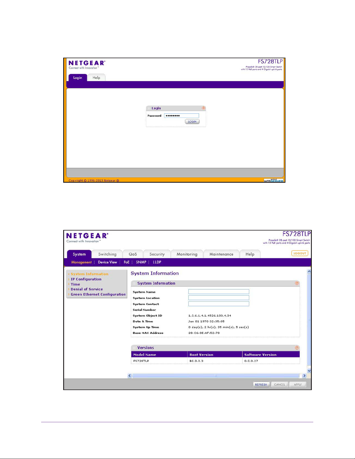
To log on to the web management interface:
1. Open a web browser.
Introduction
11
ProSAFE FS526Tv2, FS726Tv2, and FS728TLP Smart Switches
2. In the browser address field, type the IP address of the smart switch.
3. Type the password in the Password field.
The default password is password. Passwords are case-sensitive.
4. Click the Login
button.
After the system authenticates you, the System Information screen displays.
Introduction
12
ProSAFE FS526Tv2, FS726Tv2, and FS728TLP Smart Switches
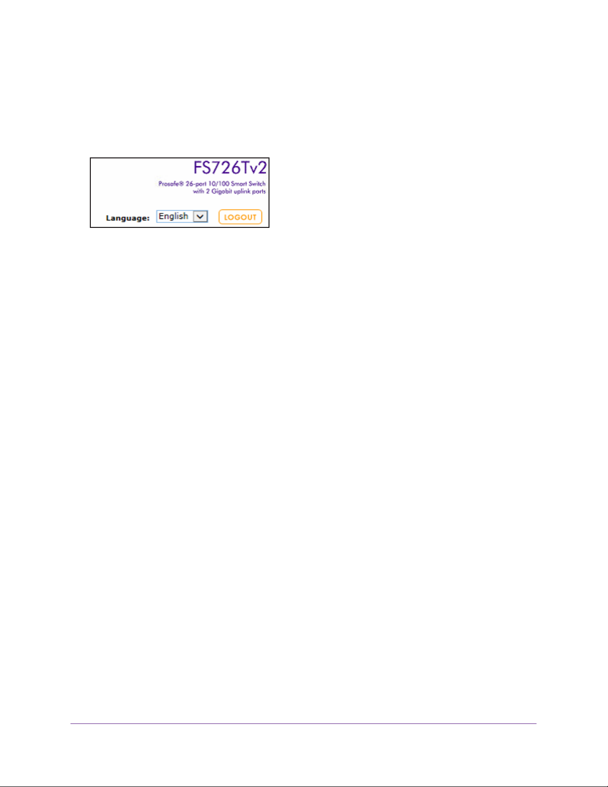
Change the Language (Model FS726Tv2 Only)
The web management interface of model FS726Tv2 provides a Language menu that lets you
select the Chinese or English language. The Language menu is located to the left of the
Logout button and is accessible from any screen.
Figure 1. Detail of the Language menu of model FS726Tv2
To change the language:
From the Language menu, select one of the following languages:
• Chinese.
• English.
The web management interface restarts with the selected language.
Allowed Characters for User-Defined Fields
On screens in the web management interface, user-defined fields can contain 1 to 159
characters, unless otherwise noted on a screen. You can use any character, except for the
following, unless specifically noted onscreen:
\ < / > * | ?
Use the Device View Screen as an Alternate Way to Configure the Smart Switch
The Device View is a Java applet that displays the ports on the smart switch. This graphic
representation provides an alternate way to navigate to configuration and monitoring
screens. The graphic representation also provides information about ports and the
configuration and status of the smart switch and its features.
Depending on the status of the port, the ports shows a green or red circle:
• A green circle indicates that the port is connected to a device.
• A red circle indicates that the port is disabled.
Depending on the status of the port, the LED of the port lights green or yellow or is off:
• A green LED for a Gigabit Ethernet port indicates that the port is enabled and operating at
a transfer rate of 1000 Mbps.
• A yellow LED for a Gigabit Ethernet port indicates that the port is enabled and operating
at a transfer rate of either 100 Mbps or 10 Mbps.
Introduction
13

ProSAFE FS526Tv2, FS726Tv2, and FS728TLP Smart Switches
• A green LED for a Fast Ethernet port indicates that the port is enabled and operating at a
transfer rate of 100 Mbps.
• A yellow LED for a Fast Ethernet port indicates that the port is enabled and operating at a
transfer rate of 10 Mbps.
• An LED that is of
f indicates that the port is not connected to a device.
Use Device View to View or Configure Ports
To access the Device View screen and view the status of a port or configure a port:
1. Select System > Device View.
The Device V
iew screen displays. The information that is displayed depends on the
switch model.
2. On the graphic representation of the smart switch, click a port.
The port menu displays.
3. Select an item from the port menu, or navigate to a submenu to select an item.
The corresponding screen displays.
Use Device View to View or Configure the Smart Switch
T o access the Device View screen and view the status of the smart switch or configure
the smart switch:
1. Select System > Device View.
The Device View screen displays. The information that is displayed depends on the
switch model.
2. On the graphic representation of the smart switch, click any area outside a port.
The system menu displays.
3. Navigate to a submenu to select an item.
The corresponding screen displays.
The following sections describe the Device View screens for model FS728TLP, model
FS726Tv2, and model FS526Tv2.
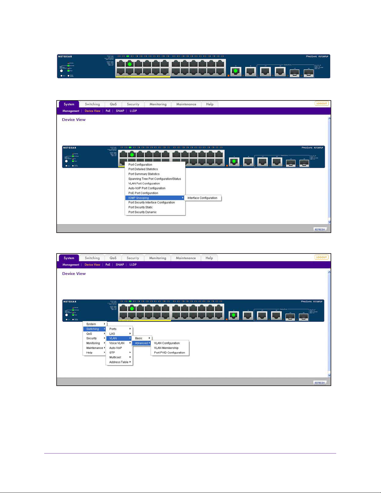
Device View Screen for Model FS728TLP
Model FS728TLP provides twenty-four 10/100BASE-T Fast Ethernet ports, four
10/100/1000BASE-T Gigabit Ethernet ports, two of which (27T and 28T) function as combo
ports, and two small form-factor pluggable (SFP) GBIC slots, both of which (27F and 28F)
function as combo ports. Power over Ethernet (PoE) is supported on ports 1 through 12.
Introduction
14
ProSAFE FS526Tv2, FS726Tv2, and FS728TLP Smart Switches
Figure 2. Model FS728TLP device view without menus
Figure 3. Model FS728TLP device view with port menus
Figure 4. Model FS728TLP device view with an example of system menus
Introduction
15
ProSAFE FS526Tv2, FS726Tv2, and FS728TLP Smart Switches
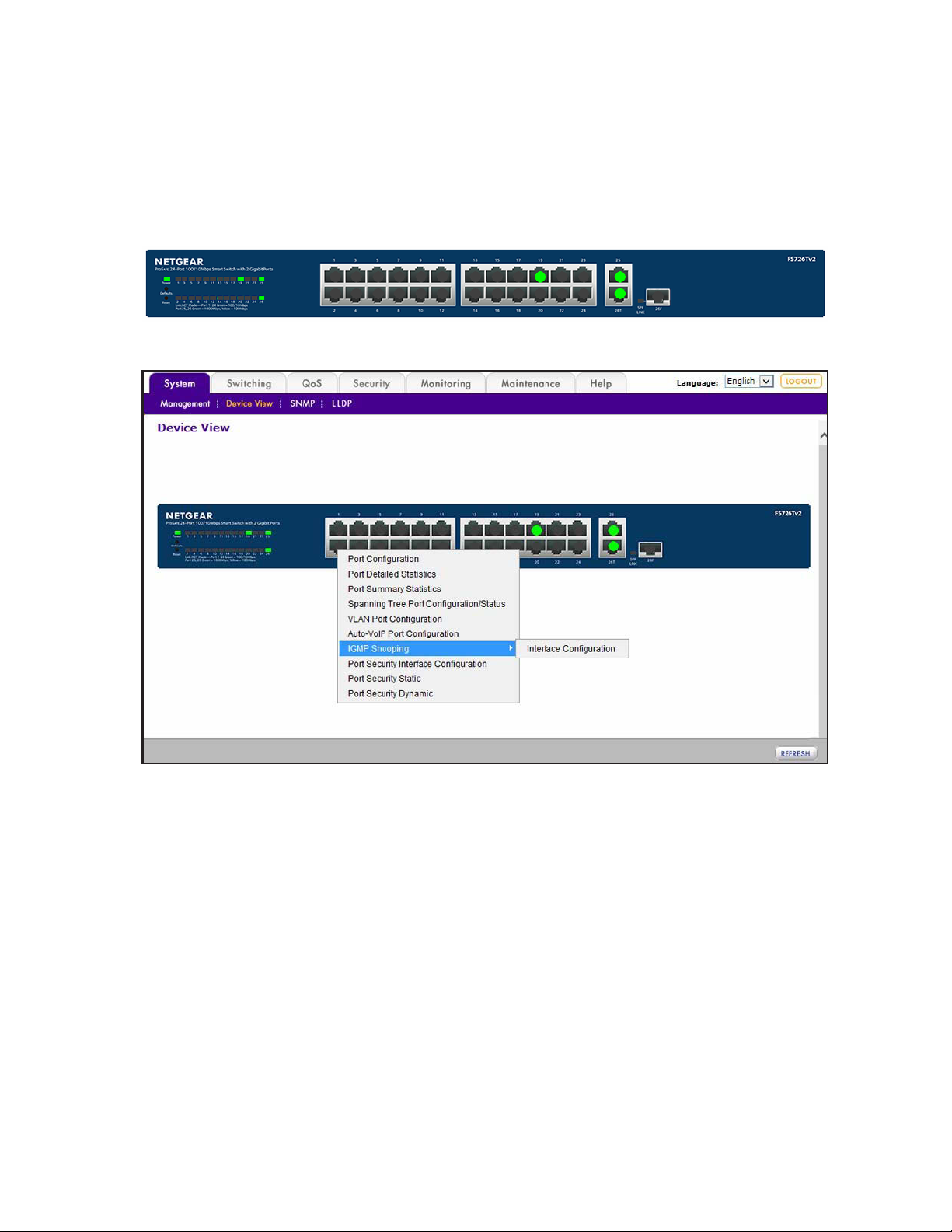
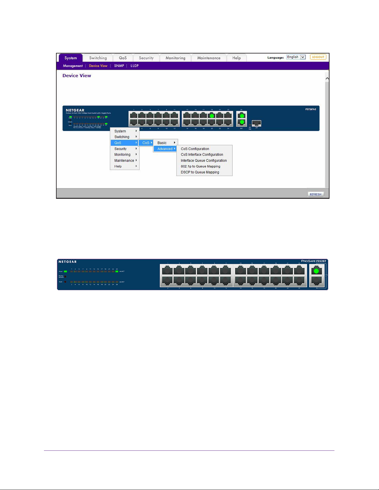
Device View Screen for Model FS726Tv2
Model FS726Tv2 provides twenty-four 10/100BASE-T Fast Ethernet ports, two
10/100/1000BASE-T Gigabit Ethernet ports, one of which (26T) functions as a combo port,
and one small form-factor pluggable (SFP) GBIC slot (26F) that functions as a combo port.
Figure 5. Model FS726Tv2 device view without menus
Figure 6. Model FS726Tv2 device view with port menus
Introduction
16
ProSAFE FS526Tv2, FS726Tv2, and FS728TLP Smart Switches
Figure 7. Model FS726Tv2 device view with an example of system menus
Device View Screen for Model FS526Tv2
Model FS526Tv2 provides twenty-four 10/100BASE-T Fast Ethernet ports and two
10/100/1000BASE-T Gigabit Ethernet ports.
Figure 8. Model FS526Tv2 device view without menus
Introduction
17
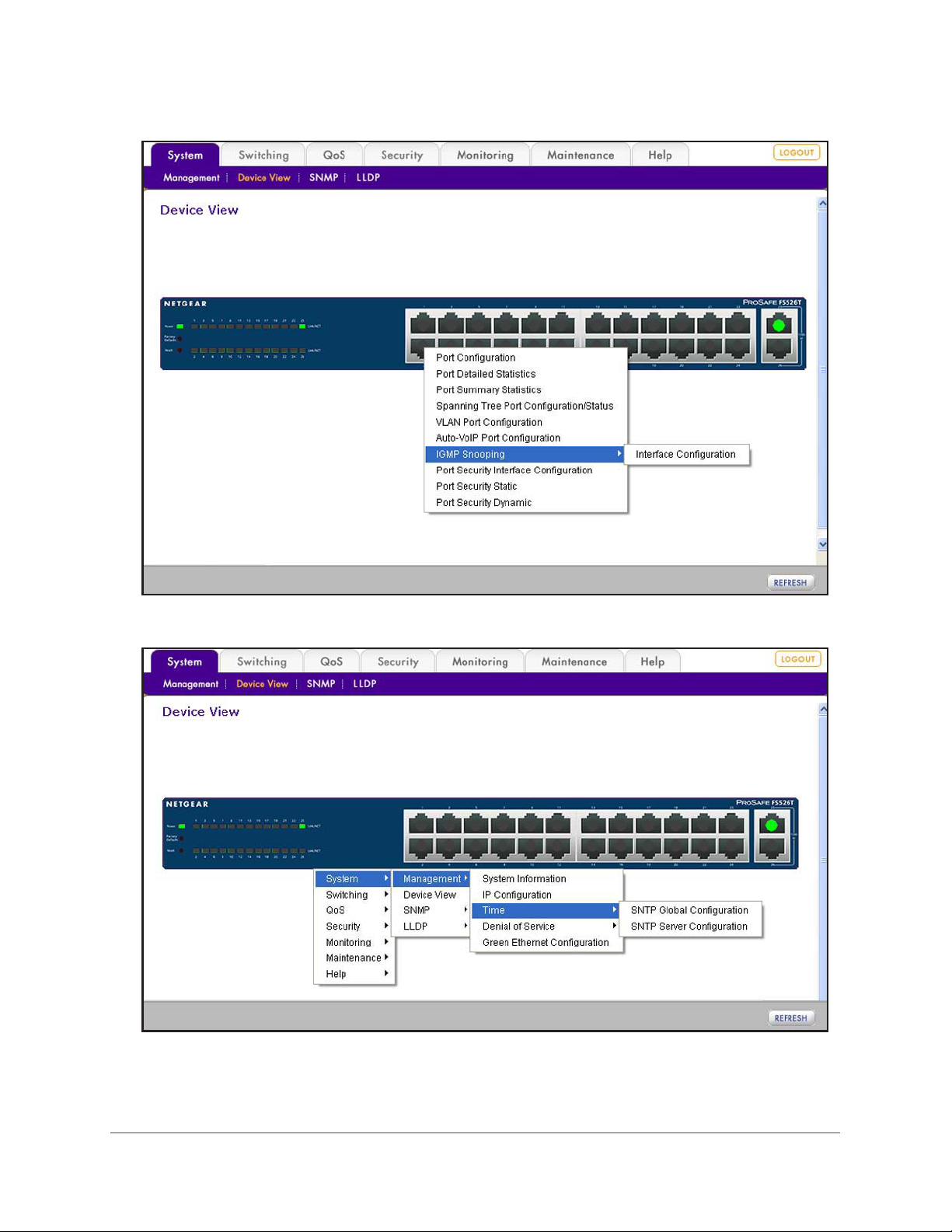
ProSAFE FS526Tv2, FS726Tv2, and FS728TLP Smart Switches
Figure 9. Model FS526Tv2 device view with port menus
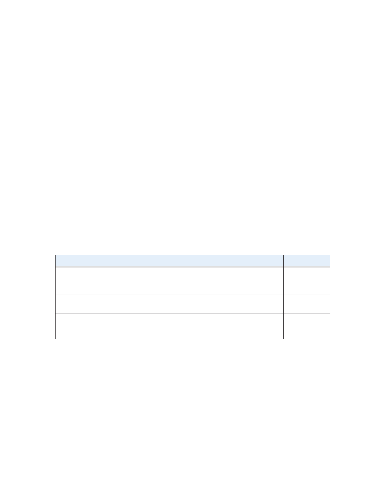
Figure 10. Model FS526Tv2 device view with an example of system menus
Introduction
18
ProSAFE FS526Tv2, FS726Tv2, and FS728TLP Smart Switches
Interface Naming Conventions
The smart switch supports physical and logical interfaces. In this guide, we refer to the
hardware ports as physical interfaces and to the link aggregation groups (LAGs) as logical
interfaces.
Ports are identified by their type and the port number. The number of the port is identified on
the front panel. You can configure the logical interfaces through the web management
interface.
Ports on Model FS728TLP
Model FS728TLP has the following ports:
• Physical ports 1–24 are Fast Ethernet ports (with ports 1–12 capable of providing PoE).
• Physical ports 25 and 26 are Gigabit Ethernet ports.
• Physical ports 27T and 28T are Gigabit Ethernet combo ports (in combination with slots
27F and 28F).
• Physical slots 27F and 28F are small form-factor pluggable (SFP) GBIC slots, which
function as combo ports (in combination with ports 27T and 28T).
The following table describes the naming convention for all interfaces available on model
FS728TLP
Table 1. Port naming conventions for model FS728TLP
Port Description Name
Physical The physical ports are numbered sequentially starting from e1. e1 through e24,
Link Aggregation Group
(LAG)
CPU Management Interface The internal switch interface responsible for the smart switch
.
and
g25 through g28
LAG interfaces are logical interfaces that are used only for
bridging functions.
base MAC address.
always listed in the MAC Address
This interface is not configurable and is
Table.
l1 through l8
c1
Ports on Model FS726Tv2
Model FS726Tv2 has the following ports:
• Physical ports 1–24 are Fast Ethernet ports.
• Physical port 25 is a Gigabit Ethernet port.
• Physical port 26T is a Gigabit Ethernet combo port (in combination with slots 26F).
• Physical slot 26F is a small form-factor pluggable (SFP) GBIC slot that functions as a
combo port (in combination with ports 26T).
Introduction
19
ProSAFE FS526Tv2, FS726Tv2, and FS728TLP Smart Switches
The following table describes the naming convention for all interfaces available on model
FS726Tv2.
Table 2. Port naming conventions for model FS526Tv2
Port Description Name
Physical The physical ports are numbered sequentially starting from e1. e1 through e24,
and
g25 and g26
Link Aggregation Group
(LAG)
CPU Management Interface The internal switch interface responsible for the smart switch
LAG interfaces are logical interfaces that are used only for
bridging functions.
base MAC address.
always listed in the MAC Address
This interface is not configurable and is
Table.
l1 through l8
c1
Ports on Model FS526Tv2
Model FS526Tv2 has the following ports:
• Physical ports 1–24 are Fast Ethernet ports.
• Physical ports 25 and 26 are Gigabit Ethernet ports.
The following table describes the naming convention for all interfaces available on model
FS526Tv2.
Table 3. Port naming conventions for model FS526Tv2
Port Description Name
Physical The physical ports are numbered sequentially starting from e1. e1 through e24,
and
g25 and g26
Link Aggregation Group
(LAG)
CPU Management Interface The internal switch interface responsible for the smart switch
LAG interfaces are logical interfaces that are used only for
bridging functions.
base MAC address.
always listed in the MAC Address
This interface is not configurable and is
Table.
l1 through l8
c1
Access Online Help from the Web Management Interface
The Help main navigation tab of the web management interface provides access to the
menus that are described in the following sections:
• Access NETGEAR Support
• Access the User Guide Online
Introduction
20
ProSAFE FS526Tv2, FS726Tv2, and FS728TLP Smart Switches
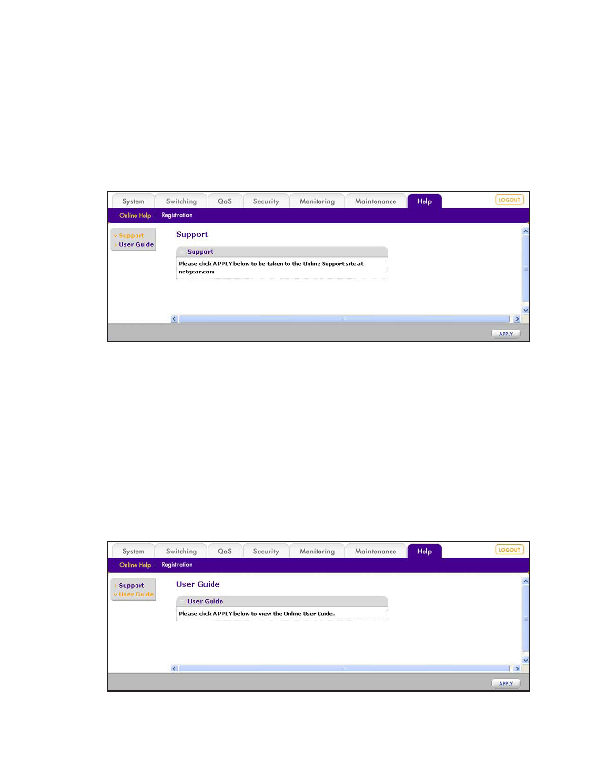
Access NETGEAR Support
If the smart switch is connected to the Internet, the Support screen provides access to the
NETGEAR support website at support.netgear.com.
To access the NETGEAR support website from the web management interface:
1. Select Help > Support.
The Support screen displays.
2. Click the Apply button.
The NETGEAR support website for the smart switch opens.
Access the User Guide Online
The ProSAFE FS526Tv2, FS726Tv2, and FS728TLP Web Management User Guide (the
user guide that you are now reading) is also available online at the NETGEAR download
center at downloadcenter.netgear.com. The smart switch needs to be connected to the
Internet.
To access the user guide online from the web management interface:
1. Select Help > > Online Help > User Guide.
The User Guide screen displays.
Introduction
21
ProSAFE FS526Tv2, FS726Tv2, and FS728TLP Smart Switches
2. Click the Apply button.
The NETGEAR download center opens.
3. Enter the model number (FS728TLP, FS726Tv2, or FS526Tv2).
4. Locate the ProSAFE FS526Tv2, FS726Tv2, and FS728TLP W
eb Management User
Guide on the product support web page.
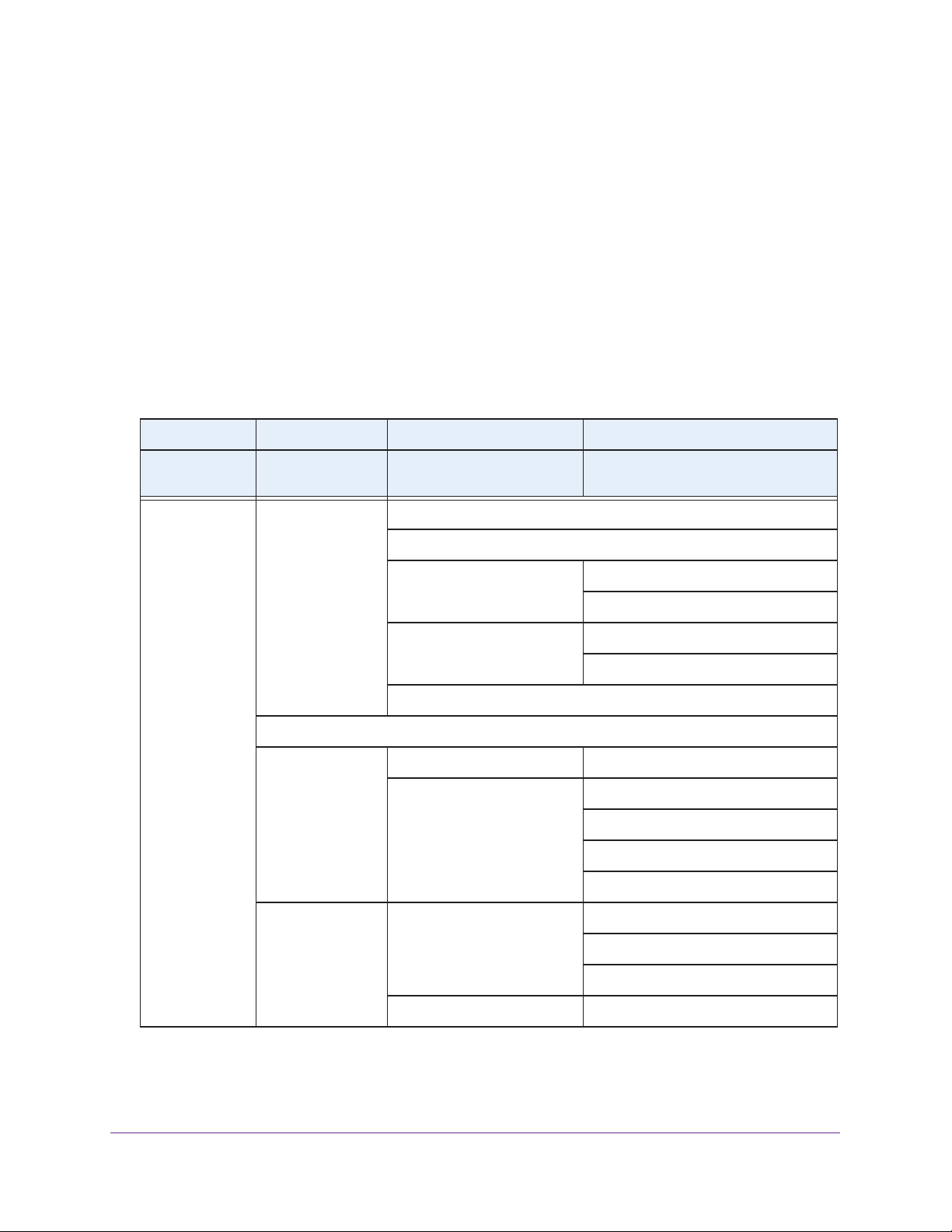
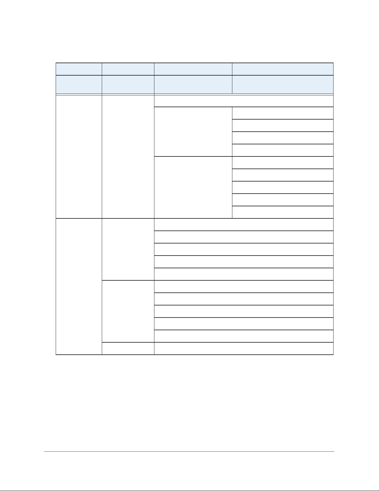
Organization of the Web Management Interface
The following table displays the organization (that is, the tree structure) of the web
management interface.
Table 4. Web management interface organization
1st level 2nd level 3rd level 4th level
Main navigation
tabs
System Management System Information
Configuration
menus
Device View
PoE
Note: Model
FS728TLP only.
Links to screens or
submenus
IP Configuration
Time SNTP Global Configuration
Denial of Service Auto-DoS Configuration
Green Ethernet Configuration
Basic PoE Configuration
Advanced PoE Configuration
Links to screens
SNTP Server Configuration
DoS Configuration
PoE Port Configuration
Timer Global Configuration
Timer Schedule Configuration
SNMP SNMP V1/V2 Community Configuration
Trap Configuration
Trap Flags
SNMP V3 User Configuration
Introduction
22

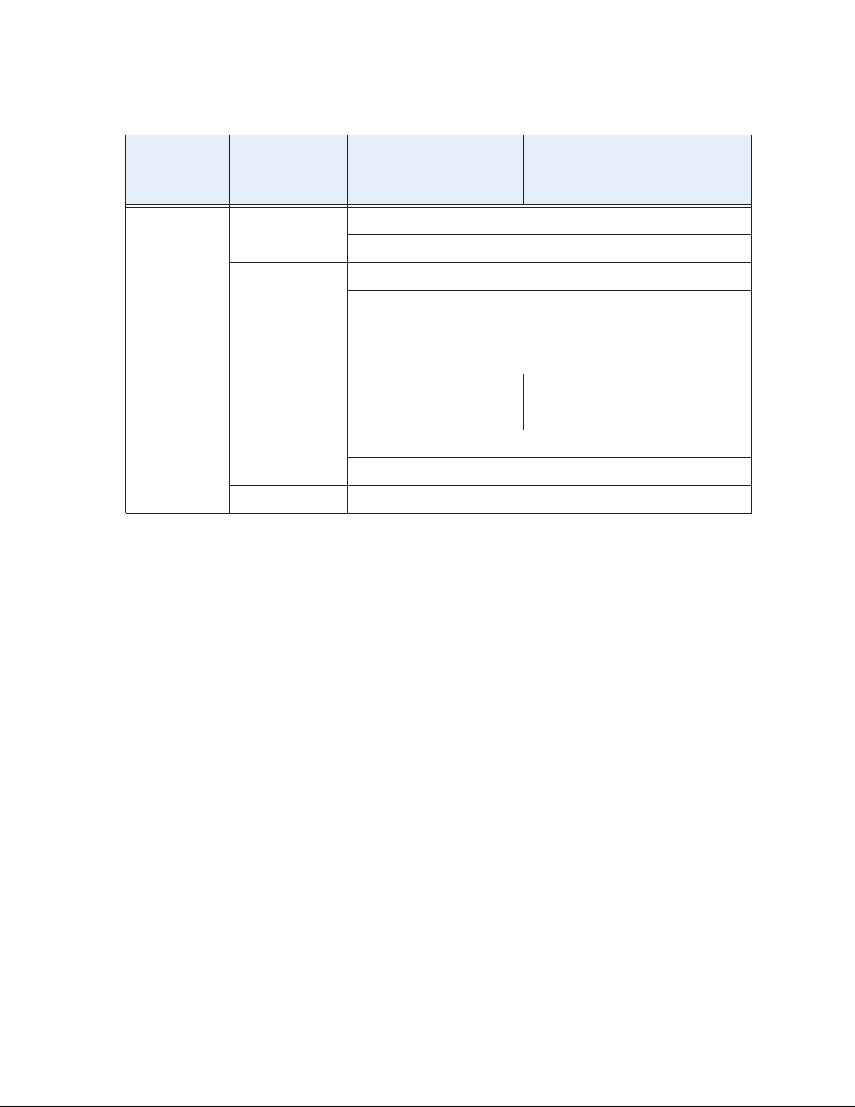
ProSAFE FS526Tv2, FS726Tv2, and FS728TLP Smart Switches
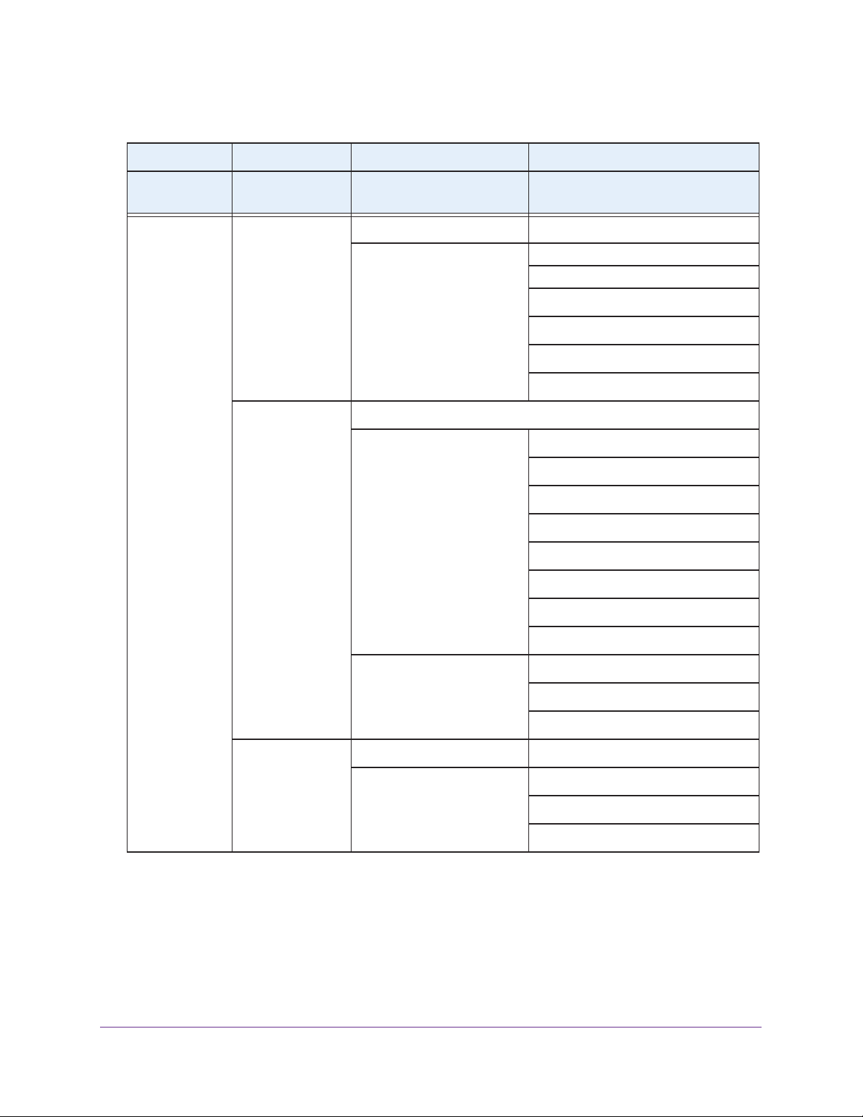
Table 4. Web management interface organization (continued)
1st level 2nd level 3rd level 4th level
Main navigation
tabs
System
(continued)
Switching Ports Port Configuration
Configuration
menus
LLDP Basic
LAG Basic LAG Configuration
Links to screens or
submenus
Advanced
Flow Control
Advanced LAG Configuration
Links to screens
LLDP Configuration
LLDP Configuration
LLDP Port Settings
LLDP-MED Network Policy
LLDP-MED Port Settings
Local Information
Neighbors Information
LAG Membership
LAG Membership
LACP Configuration
VLAN Basic
Advanced
Voice VLAN Basic
Advanced
Auto-VoIP
LACP Port Configuration
VLAN Configuration
VLAN Configuration
VLAN Membership
Port PVID Configuration
Properties
Properties
Port Setting
OUI
Introduction
23
ProSAFE FS526Tv2, FS726Tv2, and FS728TLP Smart Switches
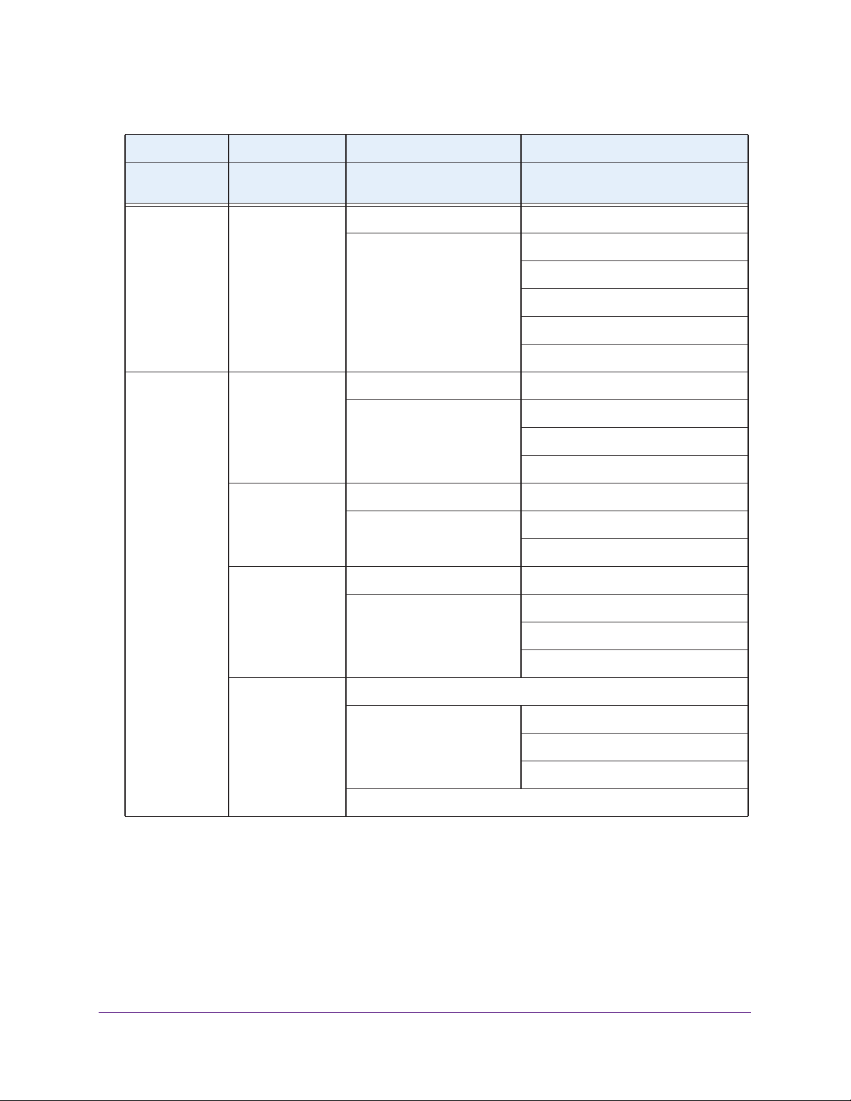
Table 4. Web management interface organization (continued)
1st level 2nd level 3rd level 4th level
Main navigation
tabs
Switching
(continued)
Configuration
menus
STP Basic
Multicast Auto-Video
Links to screens or
submenus
Advanced
IGMP Snooping IGMP Snooping Configuration
Links to screens
STP Configuration
STP Configuration
CST Configuration
CST Port Configuration
CST Port Status
RSTP
STP Statistics
IGMP Snooping Interface Configuration
IGMP Snooping Table
MFDB Table
MFDB Statistics
IGMP Snooping VLAN Configuration
Multicast Group Configuration
Multicast Group Membership
IGMP Snooping Querier Querier Configuration
Querier VLAN Configuration
Querier VLAN Status
Address Table Basic Address Table
Advanced Dynamic Addresses
Address Table
Static MAC Address
Introduction
24
ProSAFE FS526Tv2, FS726Tv2, and FS728TLP Smart Switches
Table 4. Web management interface organization (continued)
1st level 2nd level 3rd level 4th level
Main navigation
tabs
QoS CoS Basic CoS Configuration
Security Management
Configuration
menus
Security
Access HTTP HTTP Configuration
Links to screens or
submenus
Advanced CoS Configuration
User Configuration Change Password
RADIUS Global Configuration
Access Control Access Profile Configuration
Links to screens
CoS Interface Configuration
Interface Queue Configuration
802.1p to Queue Mapping
DSCP to Queue Mapping
Server Configuration
Accounting Server Configuration
Access Rule Configuration
Port Authentication Basic 802.1X Configuration
Advanced 802.1X Configuration
Port Authentication
Port Summary
Traffic Control Storm Control
Port Security Port Security Configuration
Interface Configuration
Security MAC Address
Protected Ports
Introduction
25
ProSAFE FS526Tv2, FS726Tv2, and FS728TLP Smart Switches
Table 4. Web management interface organization (continued)
1st level 2nd level 3rd level 4th level
Main navigation
tabs
Security
(continued)
Monitoring Ports Switch Statistics
Configuration
menus
ACL ACL Wizard
Links to screens or
submenus
Basic MAC ACL
Advanced IP ACL
Port Statistics
Port Detailed Statistics
Links to screens
MAC Rules
MAC Binding Configuration
Binding Table
IP Rules
IP Extended Rules
IP Binding Configuration
Binding Table
EAP Statistics
Cable Test
Logs Memory Log
FLASH Log
Server Log
Trap Log
Event Logs
Port Mirroring Port Mirroring
Introduction
26
ProSAFE FS526Tv2, FS726Tv2, and FS728TLP Smart Switches
Table 4. Web management interface organization (continued)
1st level 2nd level 3rd level 4th level
Main navigation
tabs
Maintenance Reset Device Reboot
Help Online Help Support
Configuration
menus
Upload TFTP File Upload
Download TFTP File Download
File Management Dual Image Dual Image Configuration
Registration Registration
Links to screens or
submenus
Factory Default
HTTP File Upload
HTTP File Download
User Guide
Links to screens
Dual Image Status
Introduction
27

2. Connect the Smart Switch to Your
Network
This chapter describes how to connect the smart switch to your network. The chapter has the
following sections:
• Connect the Smart Switch to the Network
• Register the Smart Switch with NETGEAR
2
28

ProSAFE FS526Tv2, FS726Tv2, and FS728TLP Smart Switches
Connect the Smart Switch to the Network
To enable remote management of the smart switch through the web management interface
or SNMP, you need to connect the smart switch to the network and configure it with network
information (an IP address, subnet mask, and default gateway). The smart switch has a
default IP address of 192.168.0.239 and a default subnet mask of 255.255.255.0.
To change the default network information on the smart switch, use one of the following three
methods:
• Dynamic assignment through DHCP. DHCP is enabled by default on the smart switch.
If you connect the smart switch to a network with a DHCP server, the smart switch
obtains its network information automatically
the automatically assigned network information.
For more information, see Use Automatic Switch Discovery for a Network with a DHCP
Server on page 29. For more information about the Smart Control Center, see
Appendix A, Smart Control Center Utilities.
• Static assignment through the Smart Control Center. If you connect the smart switch
to a network that does not have a DHCP server
static IP address, subnet mask, and default gateway
. Use the Smart Control Center to discover
, use the Smart Control Center to assign a
.
For more information, see Use Automatic Switch Discovery for a Network without a
DHCP Server on page 32. For more information about the Smart Control Center, see
Appendix A, Smart Control Center Utilities.
• Static assignment by connecting from local computer. If you do not want to use the
Smart Control Center to assign a static address, you can connect to the smart switch
from a computer (administrative system) in the 192.168.0.0/24 network and change the
settings by using the web management interface on the smart switch.
For information about how to set the IP address on the computer so it is in the same
subnet as the default IP address of the smart switch, see Configure the Network Settings
from a Local Computer on page 34.
Use Automatic Switch Discovery for a Network with a DHCP Server
This section describes how to set up your smart switch in a network that has a DHCP server.
The DHCP client on the smart switch is enabled by default. When you connect the smart
switch to your network, the DHCP server automatically assigns an IP address to the smart
switch. Use the Smart Control Center to discover the IP address that is automatically
assigned to the smart switch.
Connect the Smart Switch to Y our Network
29

ProSAFE FS526Tv2, FS726Tv2, and FS728TLP Smart Switches
To install the smart switch in a network with a DHCP server and access the smart
switch over the web management interface:
1. Install the Smart Control Center on your computer in your network.
The Smart Control Center application is on the resource CD that came in the product
package.
2. Connect the smart switch to the network, which includes a DHCP server.
For more information, see the installation guide and hardware installation guide for the
smart switch.
3. Turn on the power to the smart switch
y connecting its power cord.
b
4. Turn off the firewall on the computer temporarily.
The firewall might prevent the Smart Control Center from discovering the smart switch.
5. Start the Smart Control Center.
The Network screen displays and the Smart Control Center discovers your smart switch.
6. If the discovery function of
you start the Smart Control Center, click the Discover
the Smart Control Center does not operate automatically when
button.
7. Make a note of the IP address that the DHCP server assigned to the smart switch.
To access the smart switch directly from a web browser without using the Smart Control
Center, you need the IP address.
Connect the Smart Switch to Y our Network
30

ProSAFE FS526Tv2, FS726Tv2, and FS728TLP Smart Switches
8. Select your smart switch by clicking the table row that displays the smart switch.
9. Click the Web Browser Access button.
The Smart Control Center displays the login screen of the smart switch.
10. Type the password in the Password field.
The default password is password. Passwords are case-sensitive.
11. Click the
Login button.
After the system authenticates you, the System Information screen displays. You can now
configure the smart switch over the web management interface.
Connect the Smart Switch to Y our Network
31

ProSAFE FS526Tv2, FS726Tv2, and FS728TLP Smart Switches
Use Automatic Switch Discovery for a Network without a DHCP Server
This section describes how to use the Smart Control Center to set up your smart switch in a
network without a DHCP server. If your network has no DHCP service, you need to assign a
static IP address to your smart switch. If you choose, you can assign it a static IP address,
even if your network has DHCP service.
To install the smart switch in a network without a DHCP server and access the smart
switch over the web management interface:
1. Install the Smart Control Center on your computer in your network.
The Smart Control Center application is on the resource CD that came in the product
package.
2. Connect the smart switch to the network, which does not include a DHCP server.
For more information, see the installation guide and hardware installation guide for the
smart switch.
3. Turn on the power to the smart switch
4. Turn off the firewall on the computer temporarily.
The firewall might prevent the Smart Control Center from discovering the smart switch.
5. Start the Smart Control Center.
The Network screen displays and the Smart Control Center discovers your smart switch.
6. If the discovery function of the Smart Control Center does not operate automatically when
you start the Smart Control Center, click the Discover
y connecting its power cord.
b
button.
Connect the Smart Switch to Y our Network
32

ProSAFE FS526Tv2, FS726Tv2, and FS728TLP Smart Switches
7. Select your smart switch by clicking the table row that displays the smart switch.
8. Click the Configure Device button.
The screen expands to display additional fields at the bottom of the screen.
9. Under DHCP
, select the Disabled radio button.
The DHCP client becomes disabled on the smart switch. The IP address fields become
available on the screen.
10. In the fields at the bottom of the screen, type the switch IP address, gateway IP address,
and subnet mask for the smart switch, and, optionally, the location and system name.
Make sure that the computer on which the Smart Control Center is installed and the smart
switch are in the same subnet.
11. Make a note of the new network settings.
12. In the Current Password field, type your password.
The Apply button becomes available.
Note: You need to enter the password every time that you use the Smart
Control Center to update the switch setting. The default password is password.
13. Click the Apply button.
The new network settings are applied to the smart switch.
14. Click the Discover button again.
Note: You might have to turn off the firewall on the computer temporarily to
enable the Smart Control Center to discover the smart switch.
Connect the Smart Switch to Y our Network
33

ProSAFE FS526Tv2, FS726Tv2, and FS728TLP Smart Switches
The Smart Control Center rediscovers the smart switch with the new network settings.
15. Select your smart switch by
16. Click the Web Browser Access
clicking the table row that displays the smart switch.
button.
The Smart Control Center displays the login screen of the smart switch.
17. Type the password in the Password field.
The default password is password. Passwords are case-sensitive.
18. Click the Login
button.
After the system authenticates you, the System Information screen displays. You can now
configure the smart switch over the web management interface.
Configure the Network Settings from a Local Computer
If you prefer not to use the Smart Control Center to configure the network information on the
smart switch, you can connect directly to the smart switch from a computer. The IP address
of the computer must be in the same subnet as the default IP address of the smart switch.
You might need to change the IP address of the computer to be on the same subnet as the
default IP address of the smart switch (192.168.0.239).
To change the network settings on a computer that is running a Microsoft Windows
operating system:
1. Write down the current network address settings of your computer before you change
them.
2. On your computer, open the Internet Protocol (TCP/IP) properties screen.
You need Windows administrator privileges to change the
TCP/IP properties.
Connect the Smart Switch to Y our Network
34

ProSAFE FS526Tv2, FS726Tv2, and FS728TLP Smart Switches
3. Set the IP address of the computer to an address in the 192.168.0.0 network, such as
192.168.0.200.
The IP address of the computer must be different from the IP address of the smart switch
but within the same subnet.
WARNING:
When you change the IP address of your computer, the computer
loses the connection to the network.
4. Click the OK button.
The computer is now set up to connect to the smart switch.
To use your computer to configure a static IP address on the smart switch:
1. Use an Ethernet cable to connect the Ethernet port of the computer directly to any port
on the smart switch.
2. Open a web browser
.
3. In the browser address field, type 192.168.0.239.
192.168.0.239 is the default IP address of the smart switch.
Connect the Smart Switch to Y our Network
35

ProSAFE FS526Tv2, FS726Tv2, and FS728TLP Smart Switches
4. Type the password in the Password field.
The default password is password. Passwords are case-sensitive.
5. Click the Login
button.
After the system authenticates you, the System Information screen displays.
6. Select System > Management > IP Configuration.
The IP configuration screen displays.
7. Select the Static IP
Address radio button.
The IP configuration is reset. Even though it seems that the fields under the Static IP
Address radio button are masked out, you can enter information in the fields.
Connect the Smart Switch to Y our Network
36

ProSAFE FS526Tv2, FS726Tv2, and FS728TLP Smart Switches
8. In the fields under the Static IP Address radio button, type the static IP address, subnet
mask, and default gateway that you want to assign to the smart switch.
9. Click the Apply button.
The settings are saved. Connectivity to the smart switch through the existing web
management session is lost.
10. (Optional) Change the network settings on your computer (if the computer is running a
Microsoft Windows operating system):
a. W
rite down the current network address settings of your computer before you change
them.
b. On your computer, open the Internet Protocol (TCP/IP) properties screen.
You need Windows administrator privileges to change the TCP/IP properties.
c. Set the IP address of the computer to an address in the same network as the static
IP address of the smart switch.
The IP address of the computer must be different from the IP address of the smart
switch but within the same subnet.
d. Click the OK button.
11. Reconnect your computer to the web management interface of the smart switch:
a. Open a web browser
.
b. In the browser address field, type the new IP address of the smart switch.
c. T
ype the password in the Password field.
The default password is password. Passwords are case-sensitive.
d. Click the
Login button.
After the system authenticates you, the System Information screen displays.
Connect the Smart Switch to Y our Network
37

ProSAFE FS526Tv2, FS726Tv2, and FS728TLP Smart Switches
Register the Smart Switch with NETGEAR
To qualify for product updates and product warranty, NETGEAR encourages you to register
your product. The first time that you connect to the smart switch while it is connected to the
Internet, you can register your product. At any time, you can register your product from the
web management interface, or you can visit the NETGEAR website for registration at
https://my.netgear.com/registration/login.aspx.
To register the smart switch with NETGEAR:
1. Select Help > Register.
The Registration screen displays.
2. Click the Register button.
A new screen displays in your browser:
Connect the Smart Switch to Y our Network
38

ProSAFE FS526Tv2, FS726Tv2, and FS728TLP Smart Switches
3. Enter the information in the blank fields.
The serial number, model number, and date of purchase are entered automatically.
4. Click the Register button.
The registration web page displays.
5. Complete the registration form.
6. Click the submit button.
The smart switch registers with NETGEAR.
Connect the Smart Switch to Y our Network
39

3. Configure Basic System Settings
This chapter describes how to configure the basic settings of the smart switch so it can function
in your network. The chapter includes the following sections:
• Configure System Information
• Configure the IP Settings and Management VLAN for the Network Interface
• Configure the Time Settings and SNTP Servers
Note: For information about how to connect the smart switch to your
network, see Chapter 2, Connect the Smart Switch to Y our Network.
3
40

ProSAFE FS526Tv2, FS726Tv2, and FS728TLP Smart Switches
Configure System Information
After you log in to the smart switch, the System Information screen displays. Use this screen
to configure and view general information for the smart switch.
To view and configure general information for the smart switch:
1. Select System > Management >
System Information.
The System Information screen displays.
2. (Optional) Specify the system fields as described in the following table.
Setting Description
System Name The name that you want to use to identify the smart switch. You can use up to 31
alphanumeric characters. The factory default is blank.
System Location The name for the location of the smart switch. Y
characters. The factory default is blank.
System Contact The name for the contact person for the smart switch. Y
alphanumeric characters. The factory default is blank.
ou can use up to 31 alphanumeric
ou can use up to 31
3. Click the Apply button.
The settings are saved.
Configure Basic System Settings
41

ProSAFE FS526Tv2, FS726Tv2, and FS728TLP Smart Switches
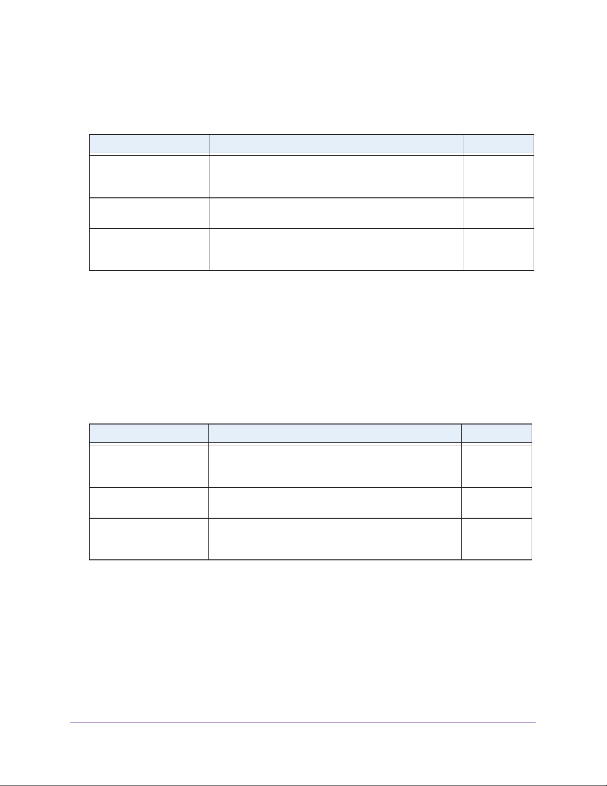
The following table describes the nonconfigurable status information that the System
Information screen displays.
Table 5. Nonconfigurable fields on the System Information screen
Field Description
System Information
Serial Number The serial number of the smart switch.
System Object ID The MIB object identifier for the smart switch.
Date & Time The current date and time.
System Up Time The number of days, hours, minutes, and seconds since the last system
restart.
Base MAC Address The Media Access Control address (MAC) address, which is the universally
assigned network address of the smart switch.
Versions
Model Name The model name of the smart switch.
Boot Version The boot code version of the smart switch.
Software Version The software version of the smart switch.
Configure the IP Settings and Management VLAN for the Network Interface
For information about how to connect the smart switch to your network, see Chapter 2,
Connect the Smart Switch to Your Network. This section describes how to change the IP
configuration and how to change the management VLAN.
Change the IP Settings
Changing the configuration of the network interface of the smart switch does not affect the
configuration of the front panel ports through which traffic is switched or routed.
To change the IP configuration of the network interface:
1. Select System > Management > IP Configuration
.
Configure Basic System Settings
42

ProSAFE FS526Tv2, FS726Tv2, and FS728TLP Smart Switches
The IP configuration screen displays.
2. Select the radio button that corresponds to the IP configuration that you want to use for the
management interface of the smart switch:
• Dynamic IP
Address (DHCP). Specifies that the smart switch obtains its IP address
through a DHCP server on your network.
• Dynamic IP Address (BOOTP). Specifies that the smart switch obtains its IP address
through a BootP server on your network.
• Static IP Address
. Specifies that the IP address, subnet mask, and default gateway
are manually configured.
a. For a static IP configuration, enter the information in the fields below the radio
button as described in the following table.
Setting Description
IP Address The IP address of the network interface. The factory default value is
192.168.0.239.
Subnet Mask The IP subnet mask for the network interface. The factory default value is
255.255.255.0.
Default Gateway The default gateway for the network interface. The factory default value is
192.168.0.254.
b. Write down the new static IP settings.
You need these settings to log back in to the web management interface.
3. Click the Apply button.
The settings are saved. Connectivity to the smart switch through the existing web
management session is lost.
Configure Basic System Settings
43

ProSAFE FS526Tv2, FS726Tv2, and FS728TLP Smart Switches
If you configured a dynamic IP address through DHCP or BOOTP, use the Smart Control
Center to discover the IP address of the smart switch. For more information, see Use
Automatic Switch Discovery for a Network with a DHCP Server on page 29.
If you assigned a static IP address, continue with the following steps.
4. (Optional) Change the network settings on your computer (if the computer is running a
Microsoft Windows operating system):
a. Write down the current network address settings of your computer before you change
them.
b. On your computer, open the Internet Protocol (TCP/IP) properties screen.
You need Windows administrator privileges to change the TCP/IP properties.
c. Set the IP address of the administrative system to an address in the same network
as the static IP address of the smart switch.
The IP address of the computer must be different from the IP address of the smart
switch but within the same subnet.
d. Click the OK button.
5. Reconnect your computer to the web management interface of the smart switch:
a. Open a web browser
.
b. In the browser address field, type the new IP address of the smart switch.
c. T
ype the password in the Password field.
The default password is password
d. Click the
Login button.
. Passwords are case-sensitive.
After the system authenticates you, the System Information screen displays.
Configure Basic System Settings
44

ProSAFE FS526Tv2, FS726Tv2, and FS728TLP Smart Switches
Change the Management VLAN
Use the management VLAN to establish an IP connection to the smart switch from a
computer that is connected to a port in the same VLAN. If not specified, the active
management VLAN ID is 1 (the default VLAN ID), which allows an IP connection to be
established through any port. Only one management VLAN can be active at a time.
If you configure the management VLAN to be different from 1, you can make an IP
connection only through a port that is part of the management VLAN. The port VLAN ID
(PVID) of the port in the management VLAN needs to be the same as the ID of the
management VLAN. For information about creating VLANs and configuring the PVID for a
port, see Configure VLANs on page 80
To change the management VLAN:
.
1. Select System > Management >
The IP Configuration screen displays.
2. Specify the VLAN ID for the management VLAN.
The VLAN ID needs to be in the range from 1 to 4093. Make sure that the VLAN that you
configure as the management VLAN exists, and make sure that the PVID of at least one
port that is member of the VLAN has the same ID as the management VLAN.
3. Click the Apply button.
The settings are saved. Connectivity to the smart switch through the existing
management VLAN is lost.
4. Reconnect your computer to a port in the new management VLAN.
IP Configuration.
Configure the Time Settings and SNTP Servers
The smart switch supports the Simple Network Time Protocol (SNTP). You can also set the
system time manually.
SNTP assures accurate network device clock time synchronization up to the millisecond. A
network SNTP server performs time synchronization. The smart switch operates only as an
SNTP client and cannot provide time services to other systems.
Strata provide time sources and define the accuracy of the reference clock. The higher the
stratum (where o [zero] is the highest), the more accurate the clock. The smart switch
receives time from stratum 0 or stratum 1 since it is itself a stratum 2 device.
The following is an example of stratums:
• Stratum 0. The time source is a real-time clock such as a GPS time system.
• Stratum 1. The time source is a server that is directly linked to a stratum 0 time source.
Stratum 1 time servers provide primary network time standards.
• Stratum 2. The time source is distanced from the stratum 1 server over a network path.
For example, a stratum 2 server receives the time over a network link, through NTP
a stratum 1 server.
Configure Basic System Settings
45
, from

ProSAFE FS526Tv2, FS726Tv2, and FS728TLP Smart Switches
The smart switch evaluates information that it receives from SNTP servers based on stratum
type and time level:
• T1. Time at which the SNTP client (that is, the smart switch) sent the original request
• T2. Time at which the SNTP server received the original request
• T3. T
• T4. T
ime at which the SNTP server sent a reply
ime at which the SNTP client (that is, the smart switch) received the reply of the
SNTP server
After you have specified one or more SNTP servers, the smart switch polls the servers for
time synchronization information and uses time levels T1 through T4 to determine the server
time.
Configure the Time Settings Manually
Use the Time Configuration screen to adjust date and time settings manually.
To configure the time manually:
1. Select System > Management > T
The Time Configuration screen displays.
ime > SNTP Global Configuration.
Configure Basic System Settings
46

ProSAFE FS526Tv2, FS726Tv2, and FS728TLP Smart Switches
2. Next to Clock Source, select the Local radio button.
The Time Zone menu is masked out.
3. In the Date field, enter the date in the DD/MM/YYYY format.
4. In the
5. Click the Apply button.
Time field, enter the time in HH:MM:SS format.
The settings are saved.
The CPU clock cycle on the smart switch maintains the time.
Manage SNTP Servers
Use the SNTP Server Configuration screen to add, view, change, and remove SNTP servers.
Add an SNTP Server
To add an SNTP server:
1. Select System > Management > T
The SNTP Server Configuration screen displays. (The following figure shows an
example.)
ime > SNTP Server Configuration.
Configure Basic System Settings
47

ProSAFE FS526Tv2, FS726Tv2, and FS728TLP Smart Switches
2. In the heading fields of the SNTP Server Configuration table, configure the settings as
described in the following table.
Setting Description
Server Type The only option is IPv4, which specifies an IPv4 SNTP server.
Address The IP address of the SNTP server. You cannot use a host name.
Port (1–65535) The port number on the SNTP server to which SNTP requests are sent. The valid
range is 1–65535.
The default port number is 123.
Priority (1–3) The priority of the SNTP server, which can be 1, 2, or 3.
sequence of servers to which SNTP requests are sent, with 1 being the default and
the highest priority. A server with a higher number has a lower priority
Version (1–4) Enter the Network Time Protocol (NTP) version number. The range is 1–4. The
default value is 4, which specifies NTPv4.
The priority determines the
.
3. Click the Add button.
The SNTP server is added to the SNTP Server Configuration table and the SNTP Server
Status table.
4. Repeat Step 2 and Step 3 to add additional SNTP servers.
You can configure up to three SNTP servers.
The SNTP Server Status table displays status information about the SNTP servers that
you have added.
Field Description
Address The IP address for the SNTP server.
Last Update Time The local date and Coordinated Universal Time (UTC) that were supplied by the
Last Attempt Time The local date and Coordinated Universal Time (UTC) when the smart switch last
The following table describes the fields of the SNTP Global Status table.
SNTP server to update the system clock of the smart switch.
queried the SNTP server
.
Last Attempt Status The status of the last SNTP request to the SNTP server:
• Other
• Success. The SNTP operation was successful and the clock was updated on
• Request T
• Bad Date Encoded. The
• Version Not Supported. The SNTP version supported by the server is not
• Server Unsynchronized.
• Server Kiss Of Death. The
: No packet was received from the SNTP server
the smart switch.
imed Out. A directed SNTP request timed out without a response
from the SNTP server.
time provided
compatible with the version configured on the smart switch.
The SNTP server is not synchronized with its
peers. (This status is indicated in the leap indicator field in a message
received from the SNTP server.)
SNTP server indicated that no further queries are
to be sent. (This status is indicated by a stratum field equal to 0 in a message
received from the SNTP server.)
by the SNTP server is not valid.
Configure Basic System Settings
48
.

ProSAFE FS526Tv2, FS726Tv2, and FS728TLP Smart Switches
Field Description
Requests The number of SNTP requests that were sent to the SNTP server since the smart
switch started.
Failed Requests
The number of failed SNTP requests that were sent to the SNTP server since the
smart switch started.
5. (Optional) Click the Refresh button.
The screen refreshes to display the most current data.
Change an SNTP Server
To change the settings for an SNTP server:
1. Select System > Management >
Time > SNTP Server Configuration.
The SNTP Server Configuration screen displays.
2. In the SNTP Server Configuration table, select the check box next to the SNTP server for
which you want to change the settings.
3. Change the settings.
You cannot change the server type or IP address.
4. Click the Apply button.
The settings are saved.
Remove an SNTP Server
To remove an SNTP server:
1. Select System > Management >
Time > SNTP Server Configuration.
The SNTP Server Configuration screen displays.
2. In the SNTP Server Configuration table, select the check box next to the SNTP server that
you want to remove.
3. Click the Delete button.
The SNTP server is removed from the SNTP Server Configuration table and the SNTP
Server Status table.
Configure the Time Settings Through SNTP
Use the Time Configuration screen to enable SNTP and view the global SNTP status. Before
you can enable SNTP, you first need to configure an SNTP server (see Manage SNTP
Servers on page 47).
To configure the time through an SNTP server:
1. Select System > Management >
Time > SNTP Global Configuration.
Configure Basic System Settings
49

ProSAFE FS526Tv2, FS726Tv2, and FS728TLP Smart Switches
The Time Configuration screen displays.
2. Next to Clock Source, select the SNTP radio button.
The Date and Time fields are masked out.
3. From the Time Zone menu, select the Coordinated Universal
Time (UTC) time zone in which
the smart switch is located.
4. Click the Apply button.
The settings are saved.
The SNTP Global Status table displays information about the SNTP client on the smart
switch.
Field Description
Version The SNTP version that the SNTP client of the smart switch supports.
Supported Mode The SNTP mode that the SNTP client of the smart switch supports. The
Last Update Time The local date and Coordinated Universal Time (UTC) that were supplied by
The following table describes the SNTP Global Status fields.
mode is always Unicast.
the SNTP server to update the system clock of the smart switch.
Configure Basic System Settings
50

ProSAFE FS526Tv2, FS726Tv2, and FS728TLP Smart Switches
Field Description
Last Attempt Time The local date and Coordinated Universal Time (UTC) when the smart
switch last queried the SNTP server.
Last Attempt Status The status of the last SNTP request to the SNTP server:
• Other: No packet was received from the SNTP server
• Success
updated on the smart switch.
• Request T
response from the SNTP server.
• Bad Date Encoded.
• Version Not Supported. The SNTP version supported by the server is
not compatible with the version configured on the smart switch.
• Server Unsynchronized
peers. (This status is indicated in the leap indicator field in a message
received from the SNTP server
• Server Kiss Of Death. The
queries are to be sent. (This status is indicated by a stratum field equal
to 0 in a message received from the SNTP server.)
. The SNTP
imed Out
operation was successful and the clock was
. A directed SNTP request timed out without a
The time provided by the SNTP server is not valid.
.
The SNTP server is not synchronized with its
.)
server indicated that no further
SNTP
.
Server IP Address The IP address of the SNTP server for the last received valid packet. If no
message has been received from any SNTP server
Address Type The address type of the SNTP server address for the last received valid
packet.
Server Stratum The stratum of the SNTP server for the last received valid packet.
Reference Clock Id The reference clock identifier of the SNTP server for the last received valid
packet.
Server Mode The mode of the SNTP server for the last received valid packet.
Unicast Server Max Entries The maximum number of unicast SNTP server entries that you can
configure on the smart switch.
Unicast Server Current
Entries
The number of current valid unicast SNTP server entries that you
configured on the smart switch.
, the field is empty
5. (Optional) Click the Refresh button.
The screen refreshes to display the most current data.
.
Configure Basic System Settings
51

4. Manage Access to the Switch
This chapter describes how to configure secure access to the smart switch. The chapter includes
the following sections:
• Manage the Password for the Smart Switch
• Configure Secure Access to the Smart Switch
4
52

ProSAFE FS526Tv2, FS726Tv2, and FS728TLP Smart Switches
Manage the Password for the Smart Switch
NETGEAR recommends that you change the default password to a secure password. The
default password is password. A secure password contains no dictionary words from any
language and contains uppercase and lowercase letters, numbers, and symbols.
If you lost your password and cannot access the web management interface, your only option
is to press the Factory Defaults button on the front panel of the smart switch to clear the
configuration and return the smart switch to the factory settings. Pressing the button for at
least two seconds causes the smart switch to reboot with factory settings.
are removed, including the password, VLAN settings, and port configurations. The password
is reset to password, which is the factory default value.
Change the Password
To change the login password for the web management interface:
All custom settings
1. Select Security > Management Security > User Configuration > Change Password
The Change Password screen displays.
2. Configure the settings as described in the following table.
Setting Description
.
Old Password The current password.
New Password The new password, which must be between 1 and
20 alphanumeric characters in length and is
Confirm Password
Minimum Password
Length
case-sensitive. The
Length field determines the minimum required length
of the password.
The minimum required length of the password. The length can be between 1 and
20 characters. The default minimum length is eight characters.
Manage Access to the Switch
setting of
the Minimum Password
53
The password that you enter
is displayed in asterisks (*).

ProSAFE FS526Tv2, FS726Tv2, and FS728TLP Smart Switches
3. Click the Apply button.
The settings are saved. The next time that you log in to the web management interface,
you need to use the new password.
Reset the Password
To reset the login password for the web management interface to the default value:
1. Select Security > Management Security > User Configuration > Change Password.
The Change Password screen displays.
2. Select the Reset Password check box.
3. Click the Apply
The settings are saved. The password is reset to password, which is the factory default
value.
button.
Configure Secure Access to the Smart Switch
You can configure global settings for HTTP sessions to the web management interface. You
can also configure an access control profile and add access rules to permit or deny selected
IP addresses access to the smart switch over HTTP or SNMP.
Configure the Global Settings for HTTP Sessions
Global settings for HTTP sessions to the web management interface include time-out
settings and the maximum number of simultaneous sessions.
To configure the global settings for HTTP sessions:
1. Select Security > Access >
The HTTP Configuration screen displays.
HTTP.
Manage Access to the Switch
54

ProSAFE FS526Tv2, FS726Tv2, and FS728TLP Smart Switches
2. Configure the settings as described in the following table.
Setting Description
Java Mode The Java applet displays a picture of the smart switch on the device view
screen (see Use the Device View Screen as an Alternate Way to Configure
the Smart Switch on page 13), allowing you to click the image of the smart
switch to select screens instead of using the navigation tabs and
configuration menus.
By default, the Enable radio button is selected for Java Mode. To disable the
Java applet, select the Disable radio button.
HTTP Session Soft Timeout
(Minutes)
HTTP Session Hard T
(Hours)
Maximum Number of HTTP
Sessions
imeout
The number of minutes that an HTTP session can be idle before a time-out
occurs and you are automatically logged out from the web management
interface.
Enter a value in the range from 0 to 60 minutes. A value of 0 corresponds to
an infinite time-out period, that is, you are not logged out when the HTTP
session is idle.
The number of hours after which an HTTP session is terminated and you are
automatically logged out from the web management interface, irrespective of
the activity level of the session.
Enter a value in the range from 0 to 168 hours. A value of 0 corresponds to
an infinite time-out period, that is, you are never logged out.
value is 24 hours.
The maximum number of simultaneous HTTP sessions that are allowed.
Enter a value in the range of from 1 to 4. The default value is 4, which allows
the maximum of four sessions.
The default value is 5 minutes.
The default
3. Click the Apply button.
The settings are saved.
Manage the Access Profile and Access Rules
You can configure settings that control access to the web management interface and the
SNMP interface. By default, you can access the web management interface and SNMP from
any IP address. However, you can restrict access to specific IP addresses, or deny access
from specific IP addresses, and you can specify the protocol (HTTP or SNMP) that is
allowed.
Configuring an access profile includes three basic steps:
1. On the Access Profile Configuration screen, create an access profile and keep it
deactivated, which is the default setting.
2. On the Access Rule Configuration screen, add one or more access rules to the profile.
3. Return to the Access Profile Configuration
screen to activate the profile.
The next section describes the detailed steps.
Manage Access to the Switch
55

ProSAFE FS526Tv2, FS726Tv2, and FS728TLP Smart Switches
Configure an Access Profile and Access Rules
To configure an access profile and access rules:
1. Select Security > Access
> Access Control > Access Profile Configuration.
The Access Profile Configuration screen displays.
2. In the Access Profile Name field, enter a name for the access profile.
The maximum length is 15 characters.
The Deactivate Profile check box is selected. Leave it selected.
3. Click the Apply button.
The settings are saved.
4. Select Security
> Access > Access
Control > Access Rule Configuration.
The Access Rule Configuration screen displays. The following figure contains examples.
Manage Access to the Switch
56

ProSAFE FS526Tv2, FS726Tv2, and FS728TLP Smart Switches
5. In the heading fields of the Access Rule Configuration table, configure the settings as
described in the following table.
Setting Description
Rule Type From the menu, select whether the rule permits or denies access to the web
management interface:
• Permit.
the criteria that you configure for the rule.
rules is denied access.
• Deny. Prohibits access to the web management interface for traf
the criteria that you configure for the rule. Any traf
rules is allowed access. Unlike MAC ACLs and IP ACLs, the rule list does not
include an implicit deny all rule at the end.
Service Type From the menu, select the type of service (protocol) that is allowed or prohibited
from accessing the web management interface:
• Snmp. The
• Http. The rule applies
Source IP Address The IP address of the client from which the management traffic originates.
Allows access to the web management interface for traffic that meets
Any traffic that does not meet the
fic that meets
fic that does not meet the
rule applies
to the SNMP interface only.
to the web management interface only.
Mask The subnet mask of the client from which the management traffic originates. The
subnet mask is a standard subnet mask, and not an inverse (wildcard) mask such
as the one you can use with IP ACLs.
Priority The priority of the rule. Enter a value in the range from 1 to 20.
The rules are validated against the incoming management request in the ascending
order of their priorities. If a rule matches, action is performed and subsequent rules
with a lower priority (that is, with a higher number) are ignored. For example, if a
source IP address of 10.10.10.10 is configured with priority 1 to permit access, and
source IP address 10.10.10.10 is configured with priority 2 to deny access, access
is permitted and the second rule is ignored.
6. Click the Add button.
The settings are saved and the rule is added to the Access Rule Configuration table.
7. Repeat Step 5 and Step 6 to add any other rules.
WARNING:
If you do not add your own IP address to the list of permitted IP
addresses, you are locked out of the web management interface
when you activate the access profile.
8. Select Security
> Access > Access
Control > Access Profile Configuration.
Manage Access to the Switch
57

ProSAFE FS526Tv2, FS726Tv2, and FS728TLP Smart Switches
The Access Profile Configuration screen displays and shows the configured rules in the
Profile Summary table.
9. Select the Activate Profile check box.
10. Click the Apply button.
The settings are saved and the profile with its rules becomes active.
The fields of the Profile Summary table are described in the following table.
Field Description
Rule Type The action the rule dictates, which is either Permit or Deny.
Service Type The type of service (protocol) that allows or prohibits access to the smart
switch:
• Http. The
• Snmp. The rule applies
Source IP Address The IP address of the client from which the management traffic originates.
Mask The subnet mask of the client from which the management traffic
originates.
Priority The priority of the rule. The rules are validated against the incoming
management request in the ascending order of their priorities. If a rule
matches, action is performed and subsequent rules with a lower priority
(that is, with a higher number) are ignored.
rule applies
to the web management interface only.
to the SNMP interface only.
11. (Optional) Click the Refresh button.
The screen refreshes to display the most current data.
Manage Access to the Switch
58

ProSAFE FS526Tv2, FS726Tv2, and FS728TLP Smart Switches
Change an Access Rule
To change an access rule:
1. Select Security > Access
> Access Control > Access Rule Configuration .
The Access Rule Configuration screen displays.
2. Select the check box to the left of the rule that you want to change.
3. Change the settings.
You cannot change the priority.
4. Click the Apply button.
The settings are saved.
Remove an Access Rule
To remove an access rule:
1. Select Security > Access
The Access Rule Configuration screen displays.
2. Select the check box to the left of the rule that you want to remove.
3. Click the Delete button.
The rule is removed from the Access Rule Configuration table and also from the Profile
Summary table on the
> Access Control > Access Rule Configuration .
Access Profile Configuration screen.
Remove the Access Profile
To remove the access profile and all its associated access rules:
1. Select Security > Access
The Access Profile Configuration screen displays.
2. Select the Remove Profile check box.
3. Click the Apply button.
The access profile name is removed, all rules are removed from the Profile Summary
table, and all rules are removed from the
Rule Configuration screen.
> Access Control > Access Profile Configuration.
Access Rule Configuration table on the
Access
Manage Access to the Switch
59

5. Configure Ports
This chapter describes how to view and configure the options for the physical ports and LAGs,
how to configure flow control, and how to configure the Auto VoIP modes. The chapter includes
the following sections:
• Configure the Options for the Physical Ports and LAGs
• Enable Flow Control
• Configure the Auto-VoIP Mode
5
60

ProSAFE FS526Tv2, FS726Tv2, and FS728TLP Smart Switches
Configure the Options for the Physical Ports and LAGs
The options that you can configure on the Port Configuration screen for each physical port
and link aggregation group (LAG) include the description, administrative mode, port speed,
auto power down mode, link trap, and maximum frame size. Other options on the Port
Configuration screen are nonconfigurable and are shown for information only.
To configure the options and view the characteristics of the physical ports, LAGs, or
both:
1. Select Switching > Ports > Port Configuration.
The Port Configuration screen displays. Because this a wide screen, it is displayed in two
figures. The first figure shows the left side of the screen. The second figure shows the
right side of the screen. Not all ports are shown in the following figures.
Configure Ports
61

ProSAFE FS526Tv2, FS726Tv2, and FS728TLP Smart Switches
2. Select whether to configure physical ports, link aggregation groups (LAGs), or both by
clicking one of the following links above the table heading:
• PORTS. Only physical ports display
• LAGS
. Only LAGs display.
. This is the default setting.
• All. Both physical ports and LAGs display.
3. Select whether to configure a single port, a group of ports, or all ports (for the sake of
simplicity in this procedure, LAGs are also considered ports):
o configure a single port, select the check box next to the port that you want to
• T
configure.
The information for the selected port displays in the menu in the table heading.
• To configure a group of ports, select the check boxes for the individual ports that you
want to configure.
• To configure all ports, select the check box at the left in the table heading.
Configure Ports
62

ProSAFE FS526Tv2, FS726Tv2, and FS728TLP Smart Switches
4. Configure the settings as described in the following table:
Setting Description
Port This is a nonconfigurable field that shows the port number or LAG number.
Description The description for the port. The string can be up to 64 characters in length.
Port Type This is a nonconfigurable field that shows the type of the port. By default, the field is
blank, indicating that the port is a regular port. If the port is not a regular port, one of
the following types can be displayed:
• Mirrored.
information, see Manage Port Mirroring on page 267
• Probe.
information, see Manage Port Mirroring on page 267
• Port Channel.
Configure a LAG on page 93
Admin Mode Specify the administrative state of the port:
• Enable.
setting.
• Disable.
The port is the source port in a port mirroring configuration. For more
.
The port is the destination port in a port mirroring configuration. For more
.
The port is a member of a LAG. For more information, see
and Manage LAG Memberships on page 95.
The port is switched on and can process traf
The port is switched of
f and cannot process traffic.
fic. This is the default
Port Speed Specify whether autonegotiation or a specific port speed and duplex mode are used
for the port:
• Auto.
• 10 Mbps Half Duplex.
• 10 Mbps Full Duplex. The port functions at 10 Mbps in full duplex mode.
• 100 Mbps Half Duplex
• 100 Mbps Full Duplex. The port
Auto Power Down
Mode
Physical Status This is a nonconfigurable field that shows the actual port speed and duplex mode.
Link Status This is a nonconfigurable field that shows the connection status of the port:
Specify whether auto power-down mode is enabled:
• Enable. If a port is down or has no link partner
• Disable. If a port is down or has no link partner, the smart switch does not
Note: Enable auto power-down mode on the Green Ethernet Configuration screen
(see Configure the Green Ethernet Features on page 225)
individual ports.
• Link Up.
• Link Down
The autonegotiation process sets the duplex mode and speed. The
maximum capability of the port (full duplex and, depending on the port,
100 Mbps or 1000 Mbps) is advertised.
The port functions at 10 Mbps in half duplex mode.
. The port functions at 100 Mbps in half duplex mode.
automatically and checks the status of the link at regular intervals.
switch reduces its power consumption and does not perform autonegotiation
while the link is down.
reduce its power consumption.
The port is connected to another device.
. The port is not connected to another device.
This is the default setting.
This is the default setting.
functions at 100 Mbps in full duplex mode.
, the port enters standby mode
The smart
you configure it for
before
Link T
rap Specify whether the smart switch sends a trap when the port link status changes:
• Enable.
default setting.
• Disable.
The smart switch sends a trap when the link status changes.
The smart switch does not send a trap when the link status changes.
Configure Ports
63
This is the

ProSAFE FS526Tv2, FS726Tv2, and FS728TLP Smart Switches
Setting Description
Maximum Frame
Size (1518 To 9216)
(Must be even)
MAC Address This is a nonconfigurable field that shows the MAC address of the port.
PortList Bit Offset This is a nonconfigurable field that shows the bit offset value that corresponds to the
ifindex
The maximum Ethernet frame size (which includes the Ethernet header, payload,
and CRC) or jumbo size that the port can support. Enter a value in the range of 1518
to 9216 bytes. The default size is 1518 bytes.
port when SNMP uses the MIB object type PortList.
This is a nonconfigurable field that shows the interface index (ifIndex) value that is
associated with the port.
5. Click the Apply button.
The settings are saved.
Enable Flow Control
802.3X flow control is a method to control congestion. When 802.3X flow control is enabled
and congestion occurs, the congested port sends a pause frame to the other end of the link to
pause the transmission of packets. When congestion is relieved, the port that was congested
sends another pause frame to restore the transmission of packets.
When congestion occurs, traffic might be dropped for small bursts of time, which can lead to
loss of high-priority traffic, network control traffic, or both. When flow control is enabled,
switches that function at lower speeds can communicate with switches that function at higher
speeds by requesting that the latter refrain from sending packets. When such a situation
occurs, transmissions are temporarily halted to prevent buf
fer overflows.
To enable global flow control:
1. Select Switching > Ports > Flow Control.
The Flow Control screen displays.
2. Next to Global Flow Control (IEEE 802.3x) Mode, select the Enable radio button.
By default, the Disable radio button is selected, and global flow control is disabled.
Configure Ports
64

ProSAFE FS526Tv2, FS726Tv2, and FS728TLP Smart Switches
3. Click the Apply button.
The settings are saved.
Configure the Auto-VoIP Mode
When you enable Auto-VoIP for a port, the port gives voice traffic automatic priority over data
traffic. Auto-VoIP checks for packets carrying the following VoIP protocols:
• Session Initiation Protocol (SIP)
• H.323
• Signalling Connection Control Part (SCCP)
VoIP frames that arrive on ports that have Auto-VoIP enabled are marked with CoS traffic
class 7.
To enable Auto-VoIP on one or more ports:
1. Select Switching > Auto-VoIP.
The
Auto-VoIP screen displays. The following figure does not show all ports.
Configure Ports
65

ProSAFE FS526Tv2, FS726Tv2, and FS728TLP Smart Switches
2. Select whether to configure a single port, a group of ports, or all ports (for the sake of
simplicity in this procedure, LAGs are also considered ports):
o configure a single port, select the check box next to the port that you want to
• T
configure.
The information for the selected port displays in the menu in the table heading.
• To configure a group of ports, select the check boxes for the individual ports that you
want to configure.
• To configure all ports, select the check box at the left in the table heading.
3. From the Auto-V
oIP Mode menu in the table heading, select Enable.
4. Click the Apply button.
The settings are saved.
Configure Ports
66

6. Configure Power over Ethernet
(Model FS728TLP Only)
This chapter describes how to configure Power over Ethernet (PoE) on model FS728TLP.
(Models FS726Tv2 and FS526Tv2 do not support PoE.) The chapter includes the following
sections:
• View the Global PoE Information and Enable PoE SNMP Traps
• Configure Dual Detection of Powered Devices
• Manage the Timer Schedules
• Configure the PoE Ports
6
67

ProSAFE FS526Tv2, FS726Tv2, and FS728TLP Smart Switches
View the Global PoE Information and Enable PoE SNMP Traps
Ports 1 through 12 can provide PoE power. The PoE Configuration screen lets you view
global PoE power information and enable PoE SNMP traps.
View the Global PoE Power Information
To view the global PoE power information:
1. Select System > PoE > Basic >
PoE Configuration.
The PoE Configuration screen displays.
The following table describes the nonconfigurable fields of the PoE Configuration screen.
Field Description
Power Status The power status (ON or OFF). Under normal circumstances, the field
displays ON. Only when a problem occurs with the PoE component of the
smart switch does the field display OFF.
Nominal Power The maximum amount of power in watts that the smart switch can deliver to
all PoE ports.
Threshold Power The threshold power in watts. The value is fixed at 93W
As long as the consumed power is less than the threshold power, that is, the
consumed power is between the nominal power and the threshold power
the smart switch can still provide power to another PoE port. If the consumed
power falls below the threshold power, the smart switch cannot provide
power to another PoE port.
Consumed Power The total amount of power in watts that is being delivered to all PoE ports.
Configure Power over Ethernet (Model FS728TLP Only)
68
.
,

ProSAFE FS526Tv2, FS726Tv2, and FS728TLP Smart Switches
2. (Optional) Click the Refresh button.
The screen refreshes to display the most current data.
Enable PoE SNMP Traps
To enable PoE SNMP traps globally:
1. Select System > PoE > Basic >
The PoE Configuration screen displays.
2. Next to Traps, select the Enable
By default, the Disable radio button is selected, and PoE traps are disabled.
3. Click the Apply button.
The settings are saved.
PoE Configuration.
radio button.
Configure Dual Detection of Powered Devices
Dual detection of powered devices (PDs) can prevent misidentification of PDs but might
increase the detection time.
To enable global dual power detection for PoE ports:
1. Select System > PoE >
The advanced PoE Configuration screen displays.
Advanced > PoE Configuration.
The only difference between this screen and the basic PoE Configuration screen (see
View the Global PoE Information and Enable PoE SNMP Traps on page 68) is the option
to configure dual detection.
2. Next to Dual Detection, select the Enable radio button.
By default, the Disable radio button is selected, and dual detection is disabled.
Configure Power over Ethernet (Model FS728TLP Only)
69

ProSAFE FS526Tv2, FS726Tv2, and FS728TLP Smart Switches
3. Click the Apply button.
The settings are saved.
Manage the Timer Schedules
You can configure one or more timer schedules that specify when a PoE port supplies power.
After you have configured and enabled the schedule, you need to attach it to one or more
PoE ports, which you do on the PoE Port Configuration screen (see Configure the PoE Ports
on page 75). You can create up to 25 timer schedules, all of which can be active
simultaneously for different PoE ports. For PoE timer schedules to function, you must also
configure an SNTP server and enable SNTP
Configuring and enabling a timer schedule involves six basic steps:
1. Configure an SNTP server (see Manage SNTP Servers on page 47).
2. Enable SNTP (see Configure the T
3. On the
Schedule on page 70
setting.
4. On the Timer Schedule Configuration screen, configure the schedule (see Configure a
T
5. Return to the Timer Global Configuration screen to enable timer schedules globally (see
Enable T
6. On the PoE Port Configuration screen, attach the schedule to one or more PoE ports
(see Configure the PoE Ports on page 75).
Timer Global Configuration screen, create a timer schedule (see Create a Timer
). Keep the timer schedule globally disabled, which is the default
imer Schedule on page 71).
imer Schedules on page 74).
ime Settings Through SNTP on page 49).
.
Create a Timer Schedule
To create a timer schedule:
1. Select System > PoE >
The Timer Global Configuration screen displays.
Configure Power over Ethernet (Model FS728TLP Only)
Advanced > Timer Global Configuration.
70

ProSAFE FS526Tv2, FS726Tv2, and FS728TLP Smart Switches
2. In the Timer Schedule Name field, enter a name for the timer schedule.
3. Click the Add button.
The schedule is added to the Timer Schedule Name table, and an ID is added. The ID
numbers are added in chronological order
, starting with 1.
Configure a Timer Schedule
To configure a timer schedule:
1. Select System > PoE >
Advanced > Timer Schedule Configuration.
The Timer Schedule Configuration screen displays.
2. From the Timer Schedule Name menu, select the timer schedule that you want to configure.
3. Configure the settings as described in the following table.
Setting Description
Shutdown Time Start Specify the time of day in the HH:MM 24-hour format when the schedule must start.
This field is required. If you do not specify a start time, the schedule cannot operate.
Shutdown Time End Specify the time of day in the HH:MM 24-hour format when the schedule must stop.
Date Start Specify the date when the schedule must start. (You can use the calendar tool.) If
you do not specify a date, the schedule starts to operate on the day that you enable
the schedule.
Date Stop Specify whether the schedule must stop on a specific date by selecting one of the
following radio buttons:
• No End Date.
• End Date. The schedule stops on the date that you specify in the field next to
the radio button. (Y
Configure Power over Ethernet (Model FS728TLP Only)
The schedule does not stop on a specific date.
ou can use the calendar tool.)
71

ProSAFE FS526Tv2, FS726Tv2, and FS728TLP Smart Switches
Setting Description
Recurrence Pattern From the Recurrence Pattern menu, select the recurrence pattern of the schedule
and configure the corresponding settings:
• Daily.
• Weekly.
• Monthly.
• Y
Note: If recurrence is not required (that is, the schedule must operate once only),
set the date in the Date Stop field to the same date as the date in the Date Start field.
Daily Specify whether the daily schedule must recur every business day or
This is the default setting.
early.
on specific days by selecting one of the following radio buttons:
• Every W
Monday though Friday.
• Every Day(s). Enter 0 to operate the schedule every day
you enter 0 and click
any other number to specify the number of consecutive days that
the schedule must operate, beginning from the start date. If you
enter a number other than 0, once the schedule has operated, it
does not restart.
Enter 1 to operate the schedule for one day only
operate the schedule for two consecutive days only
operate the schedule for three consecutive days only, and so on.
eekDay. The
schedule operates every business day,
. (After
Apply, the screen does not display 0.) Enter
, enter 2 to
, enter 3 to
Weekly Specify whether the weekly schedule must operate every week or in
specific weeks by entering a number in the Every W
specify the days of the week on which the schedule must operate by
selecting one or more check boxes next to W
• Every Week(s)
the days that you select from the Weekday check boxes. (After you
enter 0 and click Apply, the screen does not display 0.) Enter any
other number to specify the number of consecutive weeks that the
schedule must operate on the days that you select from the
Weekday check boxes. If you enter a number other than 0, once
the schedule has operated, it does not restart.
Enter 1 to operate the schedule for only one week on the days that
you select from the W
schedule for only two consecutive weeks on the days that you
select from the Weekday check boxes, enter 3 to operate the
schedule for only three consecutive weeks on the days that you
select from the Weekday check boxes, and so on.
• W
eekday. Select the check boxes for the days of the week on
which the schedule must operate.
For example, to operate the schedule on August 1, 2013 and August 8,
2013, enter 1-Aug-2013 (a Thursday) in the Date Start field, enter 2 in
the Every Week(s) field, and select the Thu check box next to
Weekday.
. Enter 0 to operate the schedule every week on
eekday check boxes, enter 2
eek(s) field and
eekday:
to operate the
Configure Power over Ethernet (Model FS728TLP Only)
72

ProSAFE FS526Tv2, FS726Tv2, and FS728TLP Smart Switches
Setting Description
Recurrence Pattern
(continued)
Monthly Specify the day of the month on which the schedule must operate and
specify whether the monthly schedule must operate every month or in
specific months.
Select the upper Day radio button to specify a fixed day in a month that
the schedule must operate and, in the upper Every Month(s) field,
specify the number of months that the schedule must operate. Or
select the lower Day radio button, use the menus to specify the relative
day of a month that the schedule must operate, and, in the lower Every
Month(s) field, specify the number of months that the schedule must
operate.
• Upper Day radio button and field and upper Every Month(s)
field.
- Upper Day field. Enter a number from 1 to 31 so specify the
day of the month on which the monthly schedule must operate.
- Upper Every Month(s) field. Enter 0 to operate the schedule
every month. (After you enter 0 and click
not display 0.) Enter any other number to specify the number of
consecutive months that the schedule must operate on the day
that you enter in the upper Day field. If you enter a number
other than 0, once the schedule has operated, it does not
restart.
Enter 1 to operate the schedule for only one month on the day
that you enter in the upper Day field, enter 2 to operate the
schedule for only two consecutive months on the day that you
enter in the upper Day field, enter 3 to operate the schedule for
only three consecutive months on the day that you enter in the
upper Day field, and so on.
• Lower Day radio button and menus and lower Every Month(s)
field.
- Lower Day menus. From the left and right menus, select the
relative day of the month on which the monthly schedule must
operate.
- Lower Every Month(s) field. Enter 0 to operate the schedule
every month. (After you enter 0 and click
not display 0.) Enter any other number to specify the number of
consecutive months that the schedule must operate on the day
that you select from the lower Day menus. If you enter a
number other than 0, once the schedule has operated, it does
not restart.
Enter 1 to operate the schedule for only one month on the day
that you select from the lower Day menus, enter 2 to operate
the schedule for only two consecutive months on the day that
you select from the lower Day menus, enter 3 to operate the
schedule for only three consecutive months on the day that you
select from the lower Day menus, and so on.
Apply , the screen does
, the screen does
Apply
Configure Power over Ethernet (Model FS728TLP Only)
73

ProSAFE FS526Tv2, FS726Tv2, and FS728TLP Smart Switches
Setting Description
Recurrence Pattern
(continued)
Yearly Specify on which day of a specific month the schedule must operate on
a yearly basis.
Select the upper Day radio button to specify a fixed day in a month that
the schedule must operate and, from the upper Month menu, select the
month in which the schedule must operate. Or select the lower Day
radio button, use the menus to specify a relative day in a month that
the schedule must operate, and, from the lower Month menu, select
the month in which the schedule must operate.
• Upper Day radio button and field and upper Month menu.
• Lower Day radio button and menus and lower Month menu.
4. Click the Apply button.
The settings are saved.
Enable Timer Schedules
- Upper Day field. Enter a number from 1 to 31 so specify the
day of the month on which the yearly schedule must operate.
- Upper Month menu. From the upper Month menu, select the
month in which the yearly schedule must operate.
- Lower Day menus. From the left and right menus, select the
relative day of the month on which the yearly schedule must
operate.
- Lower Month menu. From the lower Month menu, select the
month in which the yearly schedule must operate.
To enable timer schedules globally:
1. Select System > PoE >
Advanced > Timer Global Configuration.
The Timer Global Configuration screen displays.
2. Next to Admin Mode, select the Enable radio button.
Configure Power over Ethernet (Model FS728TLP Only)
74

ProSAFE FS526Tv2, FS726Tv2, and FS728TLP Smart Switches
3. Click the Apply button.
All timer schedules that you have configured are now enabled. You now can attach a
timer schedule to one or more ports. For more information, see Configure the PoE Ports
on page 75.
Remove a Timer Schedule
To remove a timer schedule:
1. Select System > PoE >
The Timer Global Configuration screen displays.
2. In the Timer Schedule Name table, select the check box to the left of the schedule that you
want to remove.
3. Click the Delete
The schedule is removed from the Timer Schedule Name table.
Note: You can delete a schedule even when it is attached to one or more
PoE ports.
button.
Advanced > Timer Global Configuration.
Configure the PoE Ports
The options that you can configure on the PoE Port Configuration screen for each physical
PoE port (ports e1 through e12) include the administrative mode, port priority level, PD
detection mode, timer schedule, power limit type, and power limit wattage. Other options on
the PoE Port Configuration screen are nonconfigurable and are shown for information only.
To configure the options and view the characteristics of the physical PoE ports:
1. Select System > PoE >
Configure Power over Ethernet (Model FS728TLP Only)
Advanced > PoE Port Configuration.
75

ProSAFE FS526Tv2, FS726Tv2, and FS728TLP Smart Switches
The PoE Port Configuration screen displays.
2. Select whether to configure a single port, a group of ports, or all ports:
• To configure a single port, select the check box next to the port that you want to
configure.
The information for the selected port displays in the menu in the table heading.
• To configure a group of ports, select the check boxes for the individual ports that you
want to configure.
• To configure all ports, select the check box at the left in the table heading.
3. Configure the settings as described in the following table:
Setting Description
Port This is a nonconfigurable field that shows the PoE port number (e1 through e12).
Admin Mode Specify the administrative state of the port:
• Enable.
(PD). This is the default setting.
• Disable
Max Power This is a nonconfigurable field that shows the maximum power in watts that the port
is capable of providing. The value is fixed at 16.2W.
The port is switched on and can provide PoE to a powered device
.
The port is switched off and cannot provide PoE to a PD.
Configure Power over Ethernet (Model FS728TLP Only)
76

ProSAFE FS526Tv2, FS726Tv2, and FS728TLP Smart Switches
Setting Description
Priority Level If the requested power exceeds the threshold power and the smart switch is unable
to supply power to all connected devices, the priority level lets you specify which
ports can still deliver power. If ports have the same priority level, a port with a lower
port number receives priority over a port with a higher port number. For example, if
e4 and e7 have the same priority level, e4 receives priority over e7.
From the Priority Level menu, select the level:
• High.
• Medium
• Low. The port has low PoE priority. This is the default setting.
Detection Mode The method that the port uses to detect a PD:
• Auto
• Pre-ieee
• ieee. The port performs four-point resistive detection (802.3af 4point) of a PD.
Class This is a nonconfigurable field that shows the class of the PD that is attached to the
port. The class defines the range of power a PD is drawing from the smart switch.
The following classes can be displayed:
• 0. 0.0–16.2W
• 1. 0.0–4.2W
• 2. 0.0–7.4W
• 3. 0.0–16.2W
The port has high PoE priority.
. The port has medium PoE priority
.
The port performs four-point resistive detection (802.3af 4point) of a PD
followed by legacy detection.
.
The port performs legacy detection of a PD.
This is the default mode.
.
This is the default setting.
.
Timer Schedule From the T imer Schedule menu, select the schedule that determines when the port
starts and stops supplying power
Manage the T
Output Voltage (Volt) This is a nonconfigurable field that shows the voltage that the port supplies to the
PD.
Output Current (mA) This is a nonconfigurable field that shows the current in milliampere (mA) that the
port supplies to the PD.
Output Power (Watt) This is a nonconfigurable field that shows the output in watts that the port supplies
to the PD.
Power Limit Type From the Power Limit Type menu, select the method by which the power is limited:
• Class.
detected class.
ignored. This is the default setting.
• User.
value that is configured in the Power Limit menu.
Power Limit (mW
att)
If the selection from the Power Limit Type is User, the power limit specifies the
maximum power in milliwatts that the port can supply to the PD. You can enter a
value from 3000 to 16200 milliwatts.
imer Schedules on page 70.
The limit of the power that the port supplies to the PD is based on the
The power limit that is configured in the Power Limit field is
The limit of the power that the port supplies to the PD is based on the
. For more information about timer schedules, see
Configure Power over Ethernet (Model FS728TLP Only)
77

ProSAFE FS526Tv2, FS726Tv2, and FS728TLP Smart Switches
Setting Description
Status This is a nonconfigurable field that shows the PoE status of the port:
• Disabled. The port does not supply power to the PD.
• DeliveringPower. The port supplies power to the PD.
• Fault
• Test. The port is in test mode.
• OtherFault
• Searching. The port is not in one of the previously described states.
• Requesting Power. The port is attached to a valid PD but does not supply
. A problem has occurred with the port.
. The port does not supply power to the PD because of an error
power because of a power management condition such as the threshold power
being exceeded.
4. Click the Apply button.
The settings are saved.
5. (Optional) Click the Refresh button.
The screen refreshes to display the most current data.
.
Configure Power over Ethernet (Model FS728TLP Only)
78

7. Configure VLANs and a V oice VLAN
This chapter describes how to configure regular VLANs and a voice VLAN. The chapter includes
the following sections:
• Configure VLANs
• Configure a Voice VLAN
7
79

ProSAFE FS526Tv2, FS726Tv2, and FS728TLP Smart Switches
Configure VLANs
Adding virtual LAN (VLAN) support to a Layer 2 switch provides some of the benefits of both
bridging and routing. Like a bridge, a VLAN switch forwards traffic based on the Layer 2
header, which is fast. Like a router, it partitions the network into logical segments, which
provides better administration, security, and management of multicast traffic.
By default, all ports on the switch are in the same broadcast domain. VLANs electronically
separate ports on the same switch into separate broadcast domains so that broadcast
packets are not sent to all the ports on a single switch. When you use a VLAN, you can group
users by logical function instead of physical location.
Each VLAN in a network has an associated VLAN ID, which appears in the IEEE 802.1Q tag
in the Layer 2 header of packets transmitted on a VLAN.
the VLAN portion of the tag, in which case the first switch port to receive the packet can either
reject it or insert a tag using its default VLAN ID.
but it can support only one default VLAN ID.
A port can handle traffic for multiple VLANs,
An end station might omit the tag, or
Note: For more information about VLANs, including configuration
examples, see Virtual Local Area Networks on page 308.
Manage Custom VLANs
The smart switch supports up to 128 VLANs. VLAN 1 is the preconfigured default VLAN, and
all port are untagged members by default. VLAN 2 (VoiceVLAN) and VLAN 3 (Auto-Video)
are also preconfigured VLANs, but no ports are part of these VLANs by default. Y
delete VLAN 1, VLAN 2, or VLAN 3.
Note: By default, all ports are untagged members of VLAN 1, the default
VLAN. However, ports that you make members of link aggregation
groups (that is, physical interfaces that function as trunk members)
lose their membership of the default VLAN. For more information
about link aggregation groups, see Chapter 8, Configure LAGs and
LAG Membership.
Add a Custom VLAN
ou cannot
To add a custom VLAN:
1. Select Switching > VLAN >
The VLAN Configuration screen displays.
Basic > VLAN Configuration.
Configure VLANs and a V oice VLAN
80

ProSAFE FS526Tv2, FS726Tv2, and FS728TLP Smart Switches
2. Configure the settings as described in the following table:
Setting Description
VLAN ID The VLAN identifier for the custom VLAN. You can enter data in this field only when
you are creating a VLAN. The range of the custom VLAN IDs is from 4 to 4093. (IDs
1, 2, and 3 are reserved for the default VLANs.)
VLAN Name The name for the custom VLAN. The length can be up to 32 alphanumeric
characters, including blanks.
Voice VLAN, and
VLAN Type The type for a custom VLAN is always Static. The type for the default VLANs is fixed
at Default.
Auto-Video.
The names for the default VLANs are fixed at Default,
3. Click the Add button.
The custom VLAN is added to the VLAN Configuration table. You can now add member
ports, LAGs, or both to the VLAN.
Change the Name of Custom VLAN
To change the name for a custom VLAN:
1. Select Switching > VLAN > Basic >
The VLAN Configuration screen displays.
2. Select the check box next to the VLAN for which you want to change the name.
VLAN Configuration.
You cannot change the name for a default VLAN.
3. Change the name.
4. Click the Apply button.
The settings are saved.
Configure VLANs and a V oice VLAN
81

ProSAFE FS526Tv2, FS726Tv2, and FS728TLP Smart Switches
Remove a Custom VLAN
To remove a custom VLAN:
1. Select Switching > VLAN >
The VLAN Configuration screen displays.
2. Select the check box next to the VLAN that you want to remove.
You cannot remove a default VLAN.
3. Click the Delete button.
The VLAN is removed.
Basic > VLAN Configuration.
Reset the VLAN Settings
To reset all default VLANs to their factory default settings and remove all custom
VLANS:
1. Select Switching > VLAN > Basic > VLAN Configuration.
The VLAN Configuration screen displays.
2. In the Reset section of the screen, select the Reset Configuration check box.
A pop-up confirmation screen displays.
3. Confirm your selection by clicking OK.
4. Click the Apply button.
The settings are saved. All default VLANs are reset to their factory default settings and all
custom VLANS are removed.
Manage VLAN Memberships
The VLAN Membership screen lets you add member ports, member LAGs, or both to a
default VLAN or custom VLAN.
A port or LAG can be a tagged (T) or untagged (U) VLAN member:
• Tagged. Frames transmitted from the port or LAG are tagged with the port VLAN ID.
• Untagged
be an untagged member of any VLAN. That is, a port or LAG can be an untagged
member of multiple VLANs. By default, all ports and LAGs are untagged members of
VLAN 1.
As an example, in the following figure, ports 6, 7, 8, and 16 are tagged members of VLAN
4 and LAG 2 is an untagged member of VLAN 4.
. Frames transmitted from the port or LAG are untagged. Each port or LAG can
Configure VLANs and a V oice VLAN
82

ProSAFE FS526Tv2, FS726Tv2, and FS728TLP Smart Switches
Figure 11. Example of VLAN members
Manage Members of a VLAN
To manage members of a VLAN:
1. Select Switching > VLAN > Advanced > VLAN Membership.
The VLAN Membership Configuration screen displays.
2. From the VLAN ID menu, select the VLAN to which you want to add ports, LAGs, or both.
The VLAN Name field automatically displays the name of the VLAN. The VLAN T ype field
automatically displays the type of VLAN (Default for VLAN 1, 2, and 3, or Static for any
other VLAN).
3. Click one or both of the orange bars below the VLAN Type field:
• PORT. Displays the physical ports.
• LAG
. Displays the link aggregation groups 1 through 8. (For more information, see
Chapter 8, Configure LAGs and LAG Membership).
Except for VLAN 1, by default, each square that is shown under a port or LAG is blank,
indicating that no port or LAG is a member of the VLAN.
Configure VLANs and a V oice VLAN
83

ProSAFE FS526Tv2, FS726Tv2, and FS728TLP Smart Switches
4. Depending on the members that you want to add, use one of the following methods to add
one or more ports, LAGs, or both to a VLAN:
• Add individual ports or LAGs to a VLAN using the orange bar. Below the
corresponding orange bar
, select one or more ports or LAGs that you want to add to
the VLAN by clicking the square below each port or LAG.
(Clicking a second time removes the port or LAG from the VLAN.)
• Add and configure all ports or LAGs using the
orange bar, click the square next to the PORT or LAG link:
- Click once to add all ports or LAGs as tagged members to the VLAN.
- Click twice to add all ports or LAGs as untagged members to the VLAN.
(Clicking a third time removes all ports or LAGs from the VLAN.)
• Add and configure all ports and LAGs using the Operation Group menu. From
the Group Operation menu, make one of the following selections:
- Untag All.
-
T ag All. Adds all ports and LAGs as tagged members to the VLAN.
-
Remove All. Removes all ports and LAGs from the VLAN.
Adds all ports and LAGs as untagged members to the VLAN.
5. Click the Apply button.
The settings are saved.
View the Members of a VLAN
To view the tagged and untagged members of a VLAN:
1. Select Switching > VLAN >
The VLAN Membership Configuration screen displays.
Advanced > VLAN Membership.
orange bar. In the corresponding
2. From the VLAN ID menu, select the VLAN for which you want to view the members.
3. Click the UNT
AGGED PORT MEMBERS
button.
The Port Members pop-up screen displays, showing the untagged ports and LAGs that
are members of the VLAN.
4. Click the TAGGED PORT MEMBERS
button.
The Port Members pop-up screen displays, showing the tagged ports and LAGs that are
members of the VLAN.
Configure VLANs and a V oice VLAN
84

ProSAFE FS526Tv2, FS726Tv2, and FS728TLP Smart Switches
Configure Port VLAN IDs for Ports and LAGs
The Port PVID Configuration screen lets you assign a port VLAN ID (PVID) to a port, LAG, or
both.
There are certain requirements for a PVID:
• A PVID must be assigned to all ports and LAGs. By default, all ports and LAGs are
assigned to PVID 1 because they are assigned to default VLAN 1. If you do not specify
another PVID, the default VLAN PVID is used for untagged or priority-tagged frames.
• If you want to change the default PVID of a port or LAG to a custom PVID, first create a
VLAN that includes the port or LAG as its member (see Manage Custom VLANs on
page 80 and Manage VLAN Memberships on page 82).
To assign a custom PVID to an interface:
1. Select Switching > VLAN >
Advanced > Port PVID Configuration.
The Port PVID Configuration screen displays. The following figure does not show all
ports.
Configure VLANs and a V oice VLAN
85

ProSAFE FS526Tv2, FS726Tv2, and FS728TLP Smart Switches
2. Select whether to configure physical ports, LAGs, or both by clicking one of the following
links above the table heading:
• PORTS. Only physical ports display
• LAGS
. Only LAGs display.
. This is the default setting.
• All. Both physical ports and LAGs display.
3. Select whether to configure a single port, a group of ports, or all ports (for the sake of
simplicity in this procedure, LAGs are also considered ports):
o configure a single port, select the check box next to the port that you want to
• T
configure.
The information for the selected port displays in the menu in the table heading.
• To configure a group of ports, select the check boxes for the individual ports that you
want to configure.
• To configure all ports, select the check box at the left in the table heading.
4. Configure the settings as described in the following table.
Setting Description
Interface This is a nonconfigurable field that shows the port number or LAG number.
PVID (1 to 4093) The VLAN ID that is assigned to untagged or priority-tagged frames that are
received on the port or LAG. The default setting is 1, the default VLAN.
Acceptable Frame T
Ingress Filtering Specify whether ingress filtering is applied:
Port Priority (0 to 7) Enter the default Class of Service (CoS) priority that is assigned to incoming
ypes Specify the types of frames that the port or LAG is allowed to receive:
• Admit All.
priority-tagged frames. Untagged or priority-tagged frames are assigned the
PVD for this port or LAG. VLAN-tagged frames are forwarded.
• VLAN Only. The
drops untagged frames or priority-tagged frames.
• Enabled. Ingress filtering is enabled for the port or LAG.
is dropped if the port or LAG is not a member of the VLAN with which the
frame is associated. In a tagged frame, the VLAN ID in the tag identifies the
VLAN. In an untagged frame, the VLAN is the PVID for the port.
• Disabled. Ingress filtering is disabled for the interface. All frames are
forwarded. This is the default setting.
untagged packets. Enter a number from 0 to 7, with 7 as the highest priority . The
default setting is 0.
The port or LAG can receive tagged, untagged, and
port can
receive and forward VLAN-tagged frames but
An incoming frame
5. Click the Apply button.
The settings are saved.
Configure VLANs and a V oice VLAN
86

ProSAFE FS526Tv2, FS726Tv2, and FS728TLP Smart Switches
Configure a Voice VLAN
VLAN 2 is the preconfigured voice VLAN without any preconfigured members. To help
ensure that the sound quality of an IP phone is safeguarded from deteriorating if the data
traffic on the port is high, configure the voice VLAN settings for ports that carry traffic from IP
phones.
Configure Global Voice VLAN Properties
The global voice VLAN properties include the voice VLAN ID (by default, VLAN 2), Class of
Service (CoS) on the VLAN, reassignment of the CoS tag value, and voice VLAN aging time.
By default, the voice VLAN is enabled. However, if the smart switch does not process voice
traffic, you can globally disable the voice VLAN.
To configure the global voice VLAN properties:
1. Select Switching > Voice VLAN >
The Properties screen displays.
Basic > Properties.
2. Configure the settings as described in the following table.
Setting Description
Voice VLAN ID Select a VLAN ID from the Voice VLAN ID menu. The VLAN IDs that are shown
in the menu list are the ones that are defined on the VLAN Configuration screen
(see Configure VLANs on page 80). You cannot select 1 as the voice VLAN ID.
Class of Service From the Class of Service menu, select the Class of Service (CoS) for packets
that arrive over the voice VLAN.
highest priority. The default setting for the voice VLAN is 6.
Configure VLANs and a V oice VLAN
87
You can select from 0 through 7, with 7 as the

ProSAFE FS526Tv2, FS726Tv2, and FS728TLP Smart Switches
Setting Description
Remark CoS Specify whether the smart switch reassigns the CoS tag value to packets that
arrive over the voice VLAN by selection one of the following radio buttons:
• Disable.
that arrive over the voice VLAN.
• Enable
arrive over the voice VLAN. This is the default setting.
Voice VLAN Aging Time In the Day, Hour, and Min fields, specify the time when the MAC address that
matches the IP phone’s Organizationally Unique Identifier (OUI) ages out.
default setting is one day. When the MAC address ages out, it is removed from
the voice VLAN.
Note: The value in the Voice VLAN Aging Time fields ensures that ports that
are automatically added to the voice VLAN are not bound to the VLAN
indefinitely.
The smart switch does not reassign the CoS tag value to packets
. The
switch reassigns the CoS tag value to packets that
smart
3. Click the Apply button.
The settings are saved.
The
To disable the voice VLAN globally:
1. Select Switching > V
oice VLAN > Basic > Properties.
The Properties screen displays.
2. Select the Disable radio button.
3. Click the Apply button.
The settings are saved.
Configure the Voice VLAN Port Setting
The Voice VLAN Port Setting screen lets you enable the voice VLAN for individual ports.
Note: You cannot enable the voice VLAN for a port that is member of a LAG.
To enable the voice VLAN for one or more ports:
1. Select Switching > V
oice VLAN > Advanced > Port Setting.
Configure VLANs and a V oice VLAN
88

ProSAFE FS526Tv2, FS726Tv2, and FS728TLP Smart Switches
The Port Setting screen displays. The following figure does not show all ports.
2. Select whether to configure a single port, a group of ports, or all ports (for the sake of
simplicity in this procedure, LAGs are also considered ports):
o configure a single port, select the check box next to the port that you want to
• T
configure.
The information for the selected port displays in the menu in the table heading.
• To configure a group of ports, select the check boxes for the individual ports that you
want to configure.
• To configure all ports, select the check box at the left in the table heading.
3. From the Voice VLAN Mode menu, select Enable
.
By default, the voice VLAN mode is disabled for all ports.
4. Click the Apply
button.
The settings are saved. The Membership field displays Active for the ports for which you
have enabled the voice VLAN mode. For all other ports, the Membership field displays
Not Active.
Configure VLANs and a V oice VLAN
89

ProSAFE FS526Tv2, FS726Tv2, and FS728TLP Smart Switches
Manage the Voice VLAN OUIs
The Organizational Unique Identifier (OUI) identifies the IP phone manufacturer. The switch
comes preconfigured with the following OUIs:
• 00:01:E3: SIEMENS
• 00:03:6B: CISCO1
• 00:12:43: CISCO2
• 00:0F:E2: H3C
• 00:60:B9: NITSUKO
• 00:D0:1E: PINTEL
• 00:E0:75: VERILINK
• 00:E0:BB: 3COM
• 00:04:0D: AVAYA
• 00:1B:4F: AVAYA2
1
You can add new OUIs and descriptions to identify the IP phones on the network or change
an OUI.
Add an OUI
To add an OUI:
1. Select Switching > Voice VLAN >
The OUI screen displays.
Advanced > OUI.
Configure VLANs and a V oice VLAN
90

ProSAFE FS526Tv2, FS726Tv2, and FS728TLP Smart Switches
2. In the Telephone OUI(s) field, type the VoIP OUI prefix.
The OUI prefix must be in the format AA:BB:CC.
3. In the Description field, type a description for the prefix.
4. Click the Add button.
The OUI is added to the OUI table.
Change an OUI
To change an OUI:
1. Select Switching > V
oice VLAN > Advanced > OUI.
The OUI screen displays.
2. Select the check box to the left of the OUI that you want to change.
3. Change the OUI.
You can change both the VoIP OUI prefix and the description.
4. Click the Apply button.
The modification is displayed in the OUI table.
Remove an OUI
To remove an OUI:
1. Select Switching > V
The OUI screen displays.
2. Select the check box to the left of the OUI that you want to remove.
3. Click the Delete button.
The OUI is removed from the OUI table.
oice VLAN > Advanced > OUI.
Restore the Default OUI Settings
To restore the default OUI settings:
1. Select Switching > V
The OUI screen displays.
2. Click the Restore Defaults button.
All OUIs are restored to their default settings and custom OUIs are removed from the OUI
table.
oice VLAN > Advanced > OUI.
Configure VLANs and a V oice VLAN
91

8. Configure LAGs and LAG
Membership
This chapter describes how to configure link aggregation groups (LAGs). The chapter includes
the following sections:
• Link Aggregation Group Concepts
• Configure a LAG
• Manage LAG Memberships
• Configure the LACP Global Priority
• Configure the LACP Port Priority
8
92

ProSAFE FS526Tv2, FS726Tv2, and FS728TLP Smart Switches
Link Aggregation Group Concepts
Link aggregation groups (LAGs), which are also referred to as channels or port channels, let
you combine multiple full-duplex Ethernet links into a single logical link. Network devices treat
the aggregation as if it were a single link, which increases fault tolerance and provides load
sharing.
The smart switch supports eight LAGs (LAG1 through LAG8), none of which have any ports
assigned to them. All LAGs are members of VLAN1, the default VLAN. Y
LAGs as members of other VLANs.
You can configure a LAG as static or dynamic, but not both:
• Static. A static LAG does not require a partner system to aggregate its member ports.
After you have added a port as a member of a static LAG, the port does not transmit or
accept LACP data units (LACPDUs).
• Dynamic. Link Aggregation Control Protocol (LACP) can automatically configure a link
between the smart switch and a partner device by using LACPDUs.
ou can also assign
Configure a LAG
The LAG Configuration screen lets you combine one or more full-duplex Ethernet links to
form a link aggregation group, which is also known as a port channel. The switch treats the
LAG as if it were a single link.
To configure one or more LAGs:
1. Select Switching > LAG > Basic >
The LAG Configuration screen displays.
LAG Configuration.
Configure LAGs and LAG Membership
93

ProSAFE FS526Tv2, FS726Tv2, and FS728TLP Smart Switches
2. Select whether to configure a single LAG, a group of LAGs, or all LAGs:
• To configure a single LAG, select the check box next to the LAG that you want to
configure.
The information for the selected LAG displays in the menu in the table heading.
• To configure a group of LAGs, select the check boxes for the individual LAGs that you
want to configure.
• To configure all LAGs, select the check box at the left in the table heading.
3. Configure the settings as described in the following table.
Setting Description
Lag Name Keep the default name (LAG1 through LAG8) or enter a custom name for the LAG.
You can enter any string of up to 15 alphanumeric characters.
Description The optional description for the LAG.
characters.
Lag ID This is a nonconfigurable field that displays the LAG identifier (1 through 8).
Link Trap Specify whether the smart switch sends an SNMP trap when the link status of the
LAG changes:
• Disable.
This is the default setting.
• Enable
Admin Mode Specify the administrative state of the LAG:
• Enable
default setting.
• Disable.
units (LACPDUs) are dropped. However
not released and remain members of the LAG.
STP Mode Specify the Spanning T ree Protocol (STP) administrative mode that is associated with
the LAG:
• Disable. STP is disabled for the LAG.
• Enable
Note: You can also change the STP mode for a LAG by making a selection from the
STP Status menu on the CST Port Configuration screen (see Configure CST on Ports
and LAGs on page 130).
The smart switch does not send a trap when the link status changes.
.
The smart switch sends a trap when the link status changes.
.
The LAG is enabled and can connect to another device.
The LAG is disabled and cannot connect to another device. LACP data
. STP is enabled for the LAG.
The length of the description can be up to 64
This is the
, ports that are members of the LAG are
This is the default setting.
LAG Type Specify the type of the LAG:
• Static.
• LACP. Link Aggregation Control Protocol (LACP) can automatically configure a
The LAG is static and does not require a partner system to aggregate its
member ports. After you have added a port as a member of a static LAG, the port
does not transmit or accept LACP data units (LACPDUs). Static is the default
setting.
link between the smart switch and a partner device by using LACPDUs.
Configure LAGs and LAG Membership
94

ProSAFE FS526Tv2, FS726Tv2, and FS728TLP Smart Switches
Setting Description
Active Ports This is a nonconfigurable field that displays which of the ports that you configured as
members of the LAG are active ports.
LAG State This is a nonconfigurable field that displays the state of the port channel:
• Link Up.
• Link Down. The LAG is not connected to another device.
The LAG is connected to another device.
4. Click the Apply button.
The settings are saved.
Note: Click a LAG in the Lag Name column (for example, click LAG2) to
display the LAG Membership screen, which is described in the
following section.
Manage LAG Memberships
The LAG Membership screen lets you add member ports to a LAG. In order to function, a
LAG requires full-duplex ports. By default, no port is a member of any LAG.
As an example, in the following figure, interfaces 18 through 21 are members of LAG 2.
Figure 12. Example of LAG members
Manage Members of a LAG
To manage members of a LAG:
1. Select Switching > LAG > Basic >
LAG Membership.
Configure LAGs and LAG Membership
95

ProSAFE FS526Tv2, FS726Tv2, and FS728TLP Smart Switches
The LAG Membership screen displays.
2. From the LAG ID menu, select the LAG to which you want to add ports.
The LAG Name field automatically displays the name of the LAG.
3. Depending on the members that you want to add, use one of the following methods to add
ports to the LAG:
• Add individual ports to a LAG using the orange bar. Below the orange bar , select
the ports that you want to add to the LAG by clicking the square below each port.
(Clicking a second time removes the port from the LAG.)
• Add all ports or LAGs using the orange bar .
In the orange bar
, click the square next
to the PORT link.
(Clicking a second time removes all ports from the LAG.)
4. Click the Apply button.
The settings are saved.
View Members of a LAG
To view the members of a LAG:
1. Select Switching > LAG > Basic >
LAG Membership.
The LAG Membership screen displays.
2. From the LAG ID menu, select the LAG for which you want to view the members.
3. Click the CURRENT MEMBERS button.
The Current Members pop-up screen displays the ports that are members of the LAG.
Configure LAGs and LAG Membership
96

ProSAFE FS526Tv2, FS726Tv2, and FS728TLP Smart Switches
Configure the LACP Global Priority
The LACP global priority (or LACP system priority) determines the aggregation priority
relative to the devices at the other ends of the links on which dynamic link aggregation is
enabled. A higher value means a lower priority. You can configure the LACP global priority for
the smart switch by specifying a priority from 0 to 65535. The default value is 32768.
To configure the global LACP priority:
1. Select Switching > LAG >
The LACP Configuration screen displays.
2. In the LACP System Priority field, type a value from 0 to 65535.
The default value is 32768.
3. Click the Apply button.
Advanced > LACP Configuration.
The settings are saved.
Configure the LACP Port Priority
The LACP port priority determines the aggregation priority relative to the ports in a dynamic
LAG. A higher value means a lower priority. The ports with the highest priority (that is, lowest
value) are the first ones that the LAG uses. You can configure the LACP port priority for each
port by specifying a priority from 0 to 255. The default value is 128.
The port time-out value specifies how long it takes before a port returns to standby status if it
does not receive any LACP data units (LACPDUs). The smart switch supports a long value
and a short value.
Configure LAGs and LAG Membership
97

ProSAFE FS526Tv2, FS726Tv2, and FS728TLP Smart Switches
To configure the global LACP priority:
1. Select Switching > LAG > Advanced > LACP Port Configuration.
The LACP Port Configuration screen displays.
2. Select whether to configure a single port, a group of ports, or all ports:
• To configure a single port, select the check box next to the port that you want to
configure.
The information for the selected port displays in the menu in the table heading.
• To configure a group of ports, select the check boxes for the individual ports that you
want to configure.
• To configure all ports, select the check box at the left in the table heading.
3. In the LACP Priority field, type a value from 0 to 255.
The default value is 128.
4. From the
• Long
Timeout menu, select the port time-out value:
. The port has a long time-out value. This is the default setting.
• Short. The port has a short time-out value.
5. Click the Apply button.
The settings are saved.
Configure LAGs and LAG Membership
98

9. Manage the Unicast Forwarding
Database
This chapter describes how to manage the unicast forwarding database. The chapter includes
the following sections:
• Forwarding Database Concepts
• View, Search, and Clear the MAC Address Table
• Configure Dynamic Address Aging
• Manage Static MAC Addresses
9
99

ProSAFE FS526Tv2, FS726Tv2, and FS728TLP Smart Switches
Forwarding Database Concepts
When the smart switch receives a packet from a MAC address, it adds the MAC address to
the forwarding database, which is also referred to as the MAC Address Table. The smart
switch uses the information in the forwarding database to determine how to propagate
incoming traffic. The forwarding database contains only unicast addresses. Multicast
addresses are stored in the multicast forwarding database (see View and Search the
Multicast Forwarding Database Table on page 112).
The forwarding database is dynamically built, but you can add static MAC addresses
manually
.
View, Search, and Clear the MAC Address Table
Use the search function to display information about the dynamically learned and manually
added MAC addresses in the forwarding database.
View and Search the MAC Address Table
To view the forwarding database and search for an entry in the forwarding database:
1. Select Switching > Address T
The Address Table screen displays.
able > Basic > Address Table.
The Total MAC Addresses field displays the total number of entries in the forwarding
database.
Manage the Unicast Forwarding Database
100
 Loading...