

Page 1
Page 2
Introduction
The NETGEAR™
Switch
simplify 10/100 me gabits per second (Mbps) switching technology so that
Model FS2105 Fast Ethernet Switch
Model FS2108 Fast Ethernet
and
small businesse s can enjoy the same high- performance networking facilities that
the corporate users enjoy. These switches boost network throughput, while
preserving your investment, so that there is no need to replace installed cabling,
desktop software, or hardware.
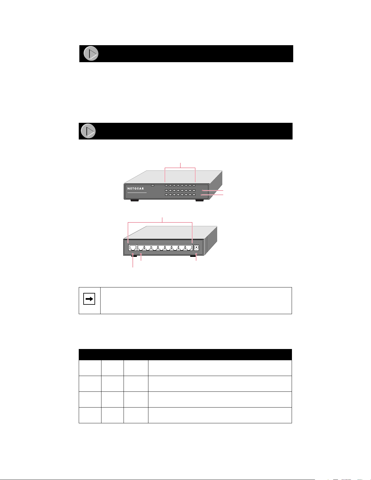
Product Illustration
Front Panel of the Model FS2108 Switch
Link/Activity LEDs
PWR
8 Port
FAST ETHERNET SWITCH
MODEL
FS2108
Rear Panel of the Model FS2108 Switch
Uplink 8 7 6 5 4 3 2 1 PWR
Port 8 Normal Power
Port 8 Uplink
1 2 3 4 5 6 7 8
10/100 Network ports
LINK/ACT
100M
FDX
110V 3A MAX
100M LEDs
FDX LEDs
input
9608FA
The Model FS2105 Fast Ethernet Switch is similar to the Model FS2108 Fast
Note:
Ethernet Sw itch, with the excepti on of three fewer RJ-45 ports and LEDs.
LEDs
This table describes the activity for LEDs on either the
Model FS2108 switch.
Label Color Activity Description
Pwr
(power)
Link/
ACT
100M Green On
FDX Green On
Green On
Off
Green On
Blinking
Power is supplied to the sw itch.
Power is disconnected.
Port connection is good.
This port is receiving or tr ansm itting data.
This port is operating at 100 Mbp s.
Off
This port is operating at 10 Mbps.
The port is operating in full-duplex mode.
Off
The port is operating in half-duplex mode.
Model FS2105/FS2108 Fa st Ethernet Switch Install ation Guide
Model FS2105 switch or the
Page 3
Network Port s
Ports 1 through 4 for the
Model FS2108 Fast Ethernet Switch
the
Model FS2105 Fast Ethernet Switch
are permanently configured for normal wiring
and ports 1 through 7 f or
for connection to a PC or a router. They are all 10/100 Mbps ports.
Normal/Uplink Ports
There are two port 5s for the
Model FS2108 Fast Ethernet Switch
the
• Port 5 Normal (or port 8 Normal) is for normal (MDI-X) wiring for direct
connection to a PC or router.
• Port 5 Uplink (or port 8 Uplink) is for uplink (MDI) wiring for connection
to a hub or a switch.
Port 5 Normal (or port 8 Normal ) and port 5 Uplink (or port 8 Uplink) can
Note:
have on ly one co nnect ion at a time . If bot h po rt s are co nne ct ed at the sa me tim e, the y
become disabled.
Model FS2105 Fast Ethernet Switch
. These ports are used as follows :
and two port 8s for
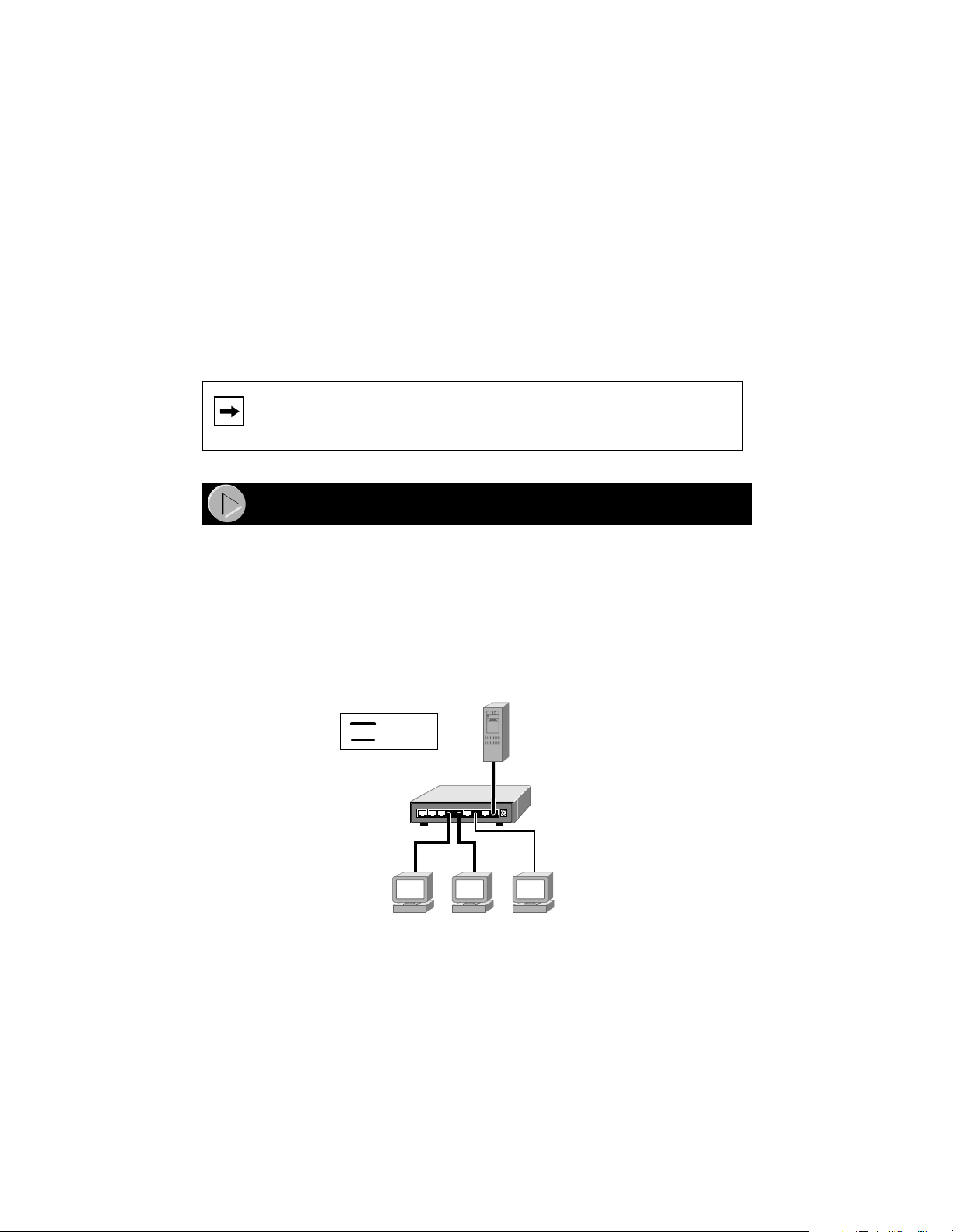
Applications
PC Workgroup
Both the
Model FS2105 Fast Ethernet Switch
and the
can be used as a desktop switch to build a small network that enables users to
have 100 Mbps access to a file server. Compared with a hub, where the network
bandwidth is shared among all users, the
switch
provides dedicated 10 or 100 Mbps bandwidth to each PC.
Model FS2105 switch
Model FS2108 Fast Ethernet Switch
or the
Model FS2108
Key
100 Mbps
10 Mbps
Model FS2108
110V 3A MAX
Up-link 8 7 6 5 4 3 2 1 PWR
Switch
9610FA
With a full-duplex adapter card installed in the se rve r, a 200 Mbps connection is
possible on the port where the server or PC is connected.
Model FS2105/FS2108 Fa st Ethernet Switch Install ation Guide
Page 4

Expanded Workgroup
Both the
Model FS2105 Fast Ethernet Switch
and the
Model FS2108 Fast Ethernet Switch
can be used to connect multiple PC workgroups.
Model FS2108 Switch
Uplink Uplink
Model EN2005
10 Mbps Hub
Up-link 5 4 3 2 1 PWR
7.5 1A
Uplink 8 7 6 5 4 3 2 1 PWR
110V 3A MAX
Model DS108
10/100 Mbps Hub
Auto 10/100 MbpsDUAL SPEED
9609FA
Installing the Switch
There are three ways to install either the Model FS2105 Fast Ethernet Switch or the Model
FS2108 Fast Ethernet Switch:
Desktop
•
• Magnetic mount (see
“Inser ti ng the Ma gn e t
”)
• Wall mount
You do not need tools for desktop or magnetic mount installation, but you do need a Phillips
screwdriver for wall mount installation.
Wall Mounting the Switch
1. Measure the distance between the mounting holes on the back of the
switch.
2. Mark the wall to match the location of the mounting holes.
3. At the marked location, insert the two screws that you received in your
package contents.
For all three installations:
Note:
• Choose a location that is near the devices to be connected.
• Make sure you are close to an electrical outlet.
• Be sure to leav e at least 2 inc hes of space all around the switch f or
ventilation .
Model FS2105/FS2108 Fa st Ethernet Switch Install ation Guide
Page 5

Magnet Mountin g the Switc h
Inserting the Magnet
1
Removing the Magnet
1
2
9640FA
2
9641FA
Connecting the Network
To connect devices to the switch:
1. Connect the devices to the 10/100 Mbps ports on the switch, using
category 5 UTP cable with an RJ-45 plug.
Ethernet specif ications limit the total cable length be tween
Note:
your PC and the switch to 328 feet (100 meters).
2. Connect the switch for specific devices:
• T o c onnec t to a PC or router, use port 5 Norma l (or port 8 Normal) . This
connection is considered “normal.”
• To connect to a hub or another switch, use port 5 Uplink (or port 8
Uplink). This connection is considered “uplink.”
3. Connect one end of the DC power adapter cable to the power outlet on
the rear panel of the switch and the other end of the power adapter
cable to the wall outlet. V erifying
Model FS2105/FS2108 Fa st Ethernet Switch Install ation Guide
Page 6

Verifyin g Insta llat io n
When power has been applied to the switch:
• The green Pwr (power) LED on the front panel is on.
• The green Link/Activity LED on each connected port is on.
When the switch is connected and operating, refer to the table in “LEDs” for
information about the LEDs and their activity.
Troubleshooting Information
Symptom Cause Solution
Green 100M
LED is off.
Green Link LED
is on and Green
FDX LED is off
when
connected to a
full-duplex
network.
Link is off on
port 5 (or 8).
Link/Activity
LED is off on a
connected port.
Port is
operating
in 10 Mbps
mode.
Port is
operating in
half-duplex
mode.
Port 5 (or 8) is
not connected
correctly.
Port
connection
is not
functioning.
Make sur e that the adapter ca rd is capab le o f a nd se t
for 100 Mbps operation.
Make sure that the connected devi ce is capable of
full-duplex transmi ssion, using autosensing. The
Model FS2105 s witch and the Model FS2108 switch
will not support a full-dup lex link that is not using
autosensing.
Make sure that only one port 5 (or 8) is connected,
not both (Uplink or Normal) .
Normal port 5 (or 8) is connected to a PC or router.
Uplink port 5 (or 8) is connected to a hub or switch.
Make sure that you are using standard, Category 5,
straight -t hrough UTP cabling.
Make sure that the attached device is powered and
there is a proper UTP connection.
Make sure that the network adapter
card installed in the PC is working.
Verify that the network adapter card
is operating at the proper speed
(10 Mbps or 100 Mbps).
Make sure that the proper cable is inst alled. Check
for miswired cable pairs or loose connectors .
For 100 Mbps oper ation, only Category 5 or better
grade cable should be used. For 10 Mbps operation,
Category 3 cable can be used.
Make sure that the length of the UTP cable fr om the
switch to the device does not exceed 328 feet (100
meters).
Model FS2105/FS2108 Fa st Ethernet Switch Install ation Guide
Page 7

Technical Specifications
Type Specification
Standards
Compatibility
Network Interface RJ-45 connector for 10BASE-T or 100BASE-TX Ethe rnet
Power Model FS2105 switch: 5.5 w max.
Physical Specifications
Dimensions: 177 x 118 x 32 mm (for both switches)
Weight: 1.25 lb; 0.6 kg
Electromagnetic
Compliance
Warranty
Switch:
Po wer Adapter: Limited lifetime warranty
For more information about customer support and technical specifications, refer
to the NETGEAR Web site:
IEEC 802-3, 10BASE-T Ethernet
IEEC 802-3u, 100BASE-T Ethernet
IEEE 802.3x Flow control; back-pressure support
Compatible with major network software , i ncluding Windows
NetWare, Mac OS, and Linux
interface
Model FS2108 switch: 8.0 w max.
CE mark, commercial; FCC Part 15 Class A; EN 55 022 (CISPR
22), Class A; VCCI Class A; and C-Tick
5 years
®
,
http://www.NETGEARinc.com/products
Model FS2105/FS2108 Fa st Ethernet Switch Install ation Guide
Page 8

© 1999 by NETGEAR, Inc. All rights reserved.
Trademarks
NETGEAR is a trademark of NETGEAR, Inc.
Microsoft and Windows are registered trademarks of Microsoft Corporation.
All other trademarks and regi s tered trademarks are the property of their respective owners.
Statement of Conditions
In the inte rest of improving internal desig n, operation al function , and/or reliabilit y, NETGEAR reserves the
right to make changes to the product described in this document without notice.
NETGEAR does not assume any l iability that may occur due to the use o r application of the product(s) or circuit l ayout(s) described
herein.
Certificate of the Manufacturer/Importer
It is hereby certified that the NETGEAR Model FS2105 Fast Ethernet Switch and Model FS2108 Fast
Ethernet Switch have been suppressed in accordance with the conditions set out in the BMPT - A mtsblVfg 243/
1991 and Vfg 46/1992. The operation of some equipment (for example, test transmitters) in accordance with
the regulations may, however, be subject to certain restrictions. Please refer to the notes in the operating
instructions.
Federal Office for Telecommunications Approvals has been notified of the placing of this equipment on the
market and has been granted the right to test the series for compliance with the regulations.
Federal Communicat ions Commission ( FCC) Comp liance Notice: Radio Frequency
Notice
This device comp lies wi th part 15 of the FCC Rules. Operation is subject to the following two conditions:
• This device may not cause harmful interferenc e.
• This devic e mus t accept any interf erence received, including inter ference that may cau s e undesired
operation .
Note: This equipment has been tested and found to comply with the limits for a Class B digital device,
pursuant to part 15 of the FCC Rules. These limits are designed to provide reasonable protection against
harmful interference in a residential installation. This equipment generates, uses, and can radiate radio
frequency energy and, if not installed and used in accordance with the instructions, may cause harmful
interference to radio communications. However, there is no guarantee that interference will not occur in a
particular installation. If this equipment does cause har m f ul interfe rence to radio or television rec eption, which
can be determined by turning the equipment of f and on, the user is encouraged to try to correct the interfer ence
by one or more of the following meas ures:
• Reorient or relocate the receiving antenna.
• Increase the sep a r ation between the equipment and receiver.
• Connect the equipment into an outlet on a circuit differ ent from that to which the receiver is connected.
• Consult the dealer or an experienced radio/TV technician for help.
EN 55 022 Declaration of Conformance
This is to ce rtify that t he N ETGEAR Mod el FS2 105 Fas t Et hernet S witch and Model FS210 8 Fas t Etherne t
Switch are shielded against the generation of radio interference in accordance with the application of Council
Directive 89/336/EEC, Article 4a. Conformity is declared by the application of EN 55 022 Class B (CISPR
22).
Canadian Department of Communications Radio Interference Regulations
This digita l apparatus (NETGEAR M odel FS2105 Fast Eth ernet Switch and Mode l FS2108 Fast Ethernet
Switch) does not exceed the Class B limits for radio-noise emissions from digital apparatus as set out in the
Radio Interference Regulations of the Canadian Department of Communications.
Règlement sur le brouillage radioélectrique du ministère des Communications
Cet appareil numérique (NETGEAR Model FS2105 Fast Ethernet Switch et Model FS2108 Fast Ethernet
Switch) respec te les limit es de bruits radioél ectriques vi sant les appare ils numériques d e classe A prescrite s
dans le Règlemen t sur le brouillage radioélectri que du ministère des Communications du Canada.
Model FS2105/FS2108 Fa st Ethernet Switch Install ation Guide
Page 9

NETGEAR, Inc.
A Bay Networks Company
4401 Great America Parkway
Santa Clara, CA 95054 USA
Phone: 888-NETGEAR
http://www.NETGEARinc.com
*M-FS2100NA-0*
 Loading...