

Page 1
NETCOMM FIBRE SERIES
WiFi Data and VoIP Gateway
NF1ADV
USER GUIDE
Page 2

2
NF1ADV User Guide
www.netcommlimited.com
YML27
WiFi Data and VoIP Gateway
Copyright
Copyright©2012 NetComm Wireless Limited. All rights reserved.
The information contained herein is proprietary to NetComm Limited. No part of this document may be translated, transcribed,
reproduced, in any form, or by any means without prior written consent of NetComm Wireless Limited.
Please note: This document is subject to change without notice.
Save Our Environment
When this equipment has reached the end of its useful life, it must be taken to a recycling centre and processed separately from
domestic waste.
The cardboard box, the plastic contained in the packaging, and the parts that make up this device can be recycled in accordance
with regionally established regulations. Never dispose of this electronic equipment along with your household waste. You may be
subject to penalties or sanctions under the law. Instead, ask for disposal instructions from your municipal government.
Please be responsible and protect our environment.
This manual covers the following products:
NetComm NF1ADV
DOCUMENT VERSION
DATE
1.0 - Initial document release
02/02/2012
Table 1 - Document Revision History
Page 3

www.netcommlimited.com
NF1ADV User Guide
3
YML38
Table of Contents
Overview ........................................................................................................................................................................................ 5
Introduction ................................................................................................................................................................................................... 5
Target Users.................................................................................................................................................................................................. 5
Prerequisites ................................................................................................................................................................................................. 5
Notation ........................................................................................................................................................................................................ 5
Product Introduction ..................................................................................................................................................................... 6
Product Overview .......................................................................................................................................................................................... 6
Package Contents ......................................................................................................................................................................................... 6
Product Features ........................................................................................................................................................................................... 6
Physical Dimensions and Indicators ............................................................................................................................................ 7
LED Indicators ............................................................................................................................................................................................... 7
Integrated Interfaces ...................................................................................................................................................................................... 8
NF1ADV Default Settings ............................................................................................................................................................................... 9
Safety and Product Care ............................................................................................................................................................. 10
Transport and Handling ............................................................................................................................................................................... 10
Installation and Configuration of the NF1ADV ............................................................................................................................ 11
Placement of your NF1ADV.......................................................................................................................................................................... 11
Connecting via an Ethernet cable ................................................................................................................................................................. 12
Connecting wirelessly .................................................................................................................................................................................. 12
Basic ............................................................................................................................................................................................ 13
Home .......................................................................................................................................................................................................... 13
Quick Setup Configuration Wizard ................................................................................................................................................................ 14
WiFi .............................................................................................................................................................................................. 18
Setup .......................................................................................................................................................................................................... 18
Security ....................................................................................................................................................................................................... 19
Configuration – Advanced Wireless Settings ................................................................................................................................................. 21
MAC Filter ................................................................................................................................................................................................... 23
Wireless Bridge ........................................................................................................................................................................................... 24
Station Info .................................................................................................................................................................................................. 24
Voice ............................................................................................................................................................................................ 25
SIP Basic Setting ......................................................................................................................................................................................... 25
SIP Advanced.............................................................................................................................................................................................. 27
SIP Debug Settings ..................................................................................................................................................................................... 28
DECT .......................................................................................................................................................................................................... 29
Management ................................................................................................................................................................................ 31
Device Settings ........................................................................................................................................................................................... 31
SNMP ......................................................................................................................................................................................................... 32
TR-069 Client .............................................................................................................................................................................................. 33
SNTP .......................................................................................................................................................................................................... 33
Access Control ............................................................................................................................................................................................ 34
Advanced Settings ...................................................................................................................................................................... 36
Layer 2 Interface .......................................................................................................................................................................................... 36
WAN Service ............................................................................................................................................................................................... 37
LAN ………………………………………………………………………………………………………………………………………………………… 39
IPv6 LAN Auto Configuration ........................................................................................................................................................................ 40
NAT …………………………………………………………………………………………………………………………………………………………41
Security ....................................................................................................................................................................................................... 44
Parental Control ........................................................................................................................................................................................... 46
Quality of Service ......................................................................................................................................................................................... 48
Routing ....................................................................................................................................................................................................... 50
DNS ............................................................................................................................................................................................................ 52
DSL ………………………………………………………………………………………………………………………………………………………….53
UPnP .......................................................................................................................................................................................................... 54
DNS Proxy .................................................................................................................................................................................................. 54
Print Server ................................................................................................................................................................................................. 55
Storage Service ........................................................................................................................................................................................... 55
Interface Grouping ....................................................................................................................................................................................... 55
Multicast – IGMP Configuration .................................................................................................................................................................... 56
SIP ALG ...................................................................................................................................................................................................... 57
Status ........................................................................................................................................................................................... 58
Diagnostics ................................................................................................................................................................................................. 58
WAN ........................................................................................................................................................................................................... 59
System Log ................................................................................................................................................................................................. 60
Statistics ..................................................................................................................................................................................................... 61
Page 4

4
NF1ADV User Guide
www.netcommlimited.com
YML27
WiFi Data and VoIP Gateway
Route .......................................................................................................................................................................................................... 63
ARP ............................................................................................................................................................................................................ 63
DHCP ......................................................................................................................................................................................................... 64
Additional Product Information ................................................................................................................................................... 65
Establishing a wireless connection................................................................................................................................................................ 65
Troubleshooting ........................................................................................................................................................................................... 66
Using the NF1ADV to make and receive telephone calls ................................................................................................................................ 68
Call feature codes ........................................................................................................................................................................................ 69
Technical Data ............................................................................................................................................................................. 71
Electrical Specifications ................................................................................................................................................................................ 71
Environmental Specifications / Tolerances .................................................................................................................................................... 71
FAQ .............................................................................................................................................................................................. 72
Appendix A: Tables...................................................................................................................................................................... 73
Appendix B: Print Server ............................................................................................................................................................. 74
For Windows Vista/7 ............................................................................................................................................................................ 74
For MAC OSX ...................................................................................................................................................................................... 77
Appendix C: Samba Server ......................................................................................................................................................... 79
For Windows Vista/7 ............................................................................................................................................................................ 79
For MAC OSX ...................................................................................................................................................................................... 79
Legal & Regulatory Information................................................................................................................................................... 80
Intellectual Property Rights ........................................................................................................................................................................... 80
FCC Regulations:......................................................................................................................................................................................... 80
RF Exposure Information .............................................................................................................................................................................. 80
Contact......................................................................................................................................................................................... 81
Page 5

www.netcommlimited.com
NF1ADV User Guide
5
YML38
Overview
Introduction
This manual provides information related to the installation, operation, and utilization of the NF1ADV.
Target Users
The individual reading this manual is presumed to have a basic understanding of telecommunications terminology and concepts.
Prerequisites
Before continuing with the installation of your NF1ADV, please confirm that you comply with the minimum system requirements
below.
Computer with Windows, Macintosh, or Linux-based operating systems with a working Ethernet adapter with TCP/IP
Protocol installed.
A Web Browser such as Internet Explorer, Netscape Navigator, Mozilla Firefox, Opera, Safari etc.
Wireless Computer System Requirements:
o
Computer with a working 802.11b, 802.11g or 802.11n wireless adapter.
Notation
The following symbols are utilised in this user manual:
-
The following note requires attention
-
The following note provides a warning
-
The following note provides relevant information
Page 6

6
NF1ADV User Guide
www.netcommlimited.com
YML27
WiFi Data and VoIP Gateway
Product Introduction
Product Overview
ADSL2/2+ Integrated Access Device.
1 x 10/100/1000 Gigabit WAN port.
4 x 10/100 LAN Ethernet port.
2 x FXS Voice ports (circuit-switched).
1 x FXO port for PSTN calling.
802.11n up to 300Mbps Wireless1 (Backward compatible with 802.11b/g).
DECT CAT-iQ 2.0 base station with DECT association button.
2 x USB host ports supporting mass storage file sharing and print serving.
WiFi Protected Setup (WPS) for wireless connectivity.
VPN pass-through (PPTP, L2TP, IPSec).
Browser based interface for configuration and management.
1. Speeds are dependent on network coverage. See your MBB provider coverage maps for more details. The total number of WiFi users can also affect data speeds.
The maximum wireless signal rate and coverage values are derived from IEEE Standard 802.11g and 802.11n specifications. The actual wireless speed and
coverage are dependent on network and environmental conditions including but not limited to the volume of network traffic, building materials and
construction/layout.
Package Contents
The NF1ADV package consists of:
1 x NF1ADV WiFi Data and VoIP Gateway.
1 x 12VDC~2.0A Power Adapter.
1 x RJ-45 Ethernet LAN Cable.
1 x RJ-11 phone Cable.
Quick Setup Guide.
Wireless Security Card.
If any of these items are missing or damaged, please contact NetComm customer care.
Product Features
Congratulations on your purchase of a NetComm NF1ADV WiFi Data and VoIP Gateway. This router is compliant with 802.11n
offering speeds up to 6 times faster than standard 802.11g based routers while still being compatible with 802.11g & 802.11b
devices. The NF1ADV is not only a Wireless Access Point, and using a Gigabit speed WAN port and doubling as a 4-port full-duplex
Ethernet Switch, connects your wired-Ethernet devices together at incredible speeds.
With speeds of up to 300Mbps* the NetComm NF1ADV WiFi Data and VoIP Gateway uses advanced MIMO (Multi-Input, MultiOutput) technology to transmit multiple steams of data in a single wireless channel giving you seamless access to multimedia
content. Robust RF signal travels farther, eliminates dead spots and extends network range. For data protection and privacy, the
NF1ADV encodes all wireless transmissions with WEP, WPA, and WPA2 encryption.
With inbuilt DHCP Server & powerful SPI firewall the NF1ADV protects your computers against intruders and most known Internet
attacks but provides safe VPN pass-through. With incredible speed and QoS function of 802.11n, NF1ADV is ideal for mediacentric applications like streaming video, gaming, and VoIP telephony allowing you to run multiple media-intense data streams
through the network at the same time, with no degradation in performance.
The NetComm NF1ADV creates a secure WiFi network, providing Internet access to users and simultaneous phone service using
your VoIP Service Provider’s network. It incorporates a DECT base station for use with cordless phones. It also incorporates a
WLAN 802.11b/g/n access point, one 10/100Mbps Ethernet port, one 10/100Mbps Ethernet WAN port and two phone ports for
making and receiving telephone calls. It features the latest security options such as WPA and WPA2 data encryption, SPI (Stateful
Packet Inspection) Firewall and VPN pass through.
Page 7

www.netcommlimited.com
NF1ADV User Guide
7
YML38
Physical Dimensions and
Indicators
LED Indicators
The NF1ADV has been designed to be placed on a desktop. All of the cables exit from the rear for better organization. The display is
visible on the front of the NF1ADV to provide you with information about network activity and the device status. See below for an
explanation of each of the indicator lights.
Table 2 - LED Indicators
LED INDICATOR
ICON
DEFINITION
Power
The power LED will be a solid green light when the device is powered
on. The power LED will flash during the device start up process.
LAN
The LAN LEDs will be a solid green light when a specific LAN
connection is established. The LED flashes on LAN port traffic
throughput.
WAN
WAN mode: The WAN LED lights up when the router is connected to
the internet via an Ethernet WAN connection.
WiFi
The LED will show a solid green light when WLAN is enabled. The LED
flashes on traffic throughput (data transfer).
WPS
The WPS LED will light up to indicate that the wireless signal has been
configured using the WiFi Protected Setup option.
Phone1
A solid blue light appears when the analogue telephone connected to
Line 1 is off-hook. The Line 1 LED will flash on an incoming call.
Phone 2
A solid green light appears when the analogue telephone connected to
Line 2 is off-hook. The Line 2 LED will flash on an incoming call.
Line
The Line LED will be on when a line cable for PSTN calls is connected
from the router to a phone port of an ADSL filter.
DSL
The DSL LED will flicker on and off when training for a DSL signal.
When a DSL signal is detected the LED will be a solid green light.
WWW
The WWW LED will light up when there is a WAN connection through
a fixed DSL connection.
DECT
The DECT LED will light up when the NF1ADV is DECT registration
mode
Page Register
This Icon will light up when a DECT phone connected to the router is
off hook. It will also flash on an incoming call.
Page 8
8
NF1ADV User Guide
www.netcommlimited.com
YML27
WiFi Data and VoIP Gateway
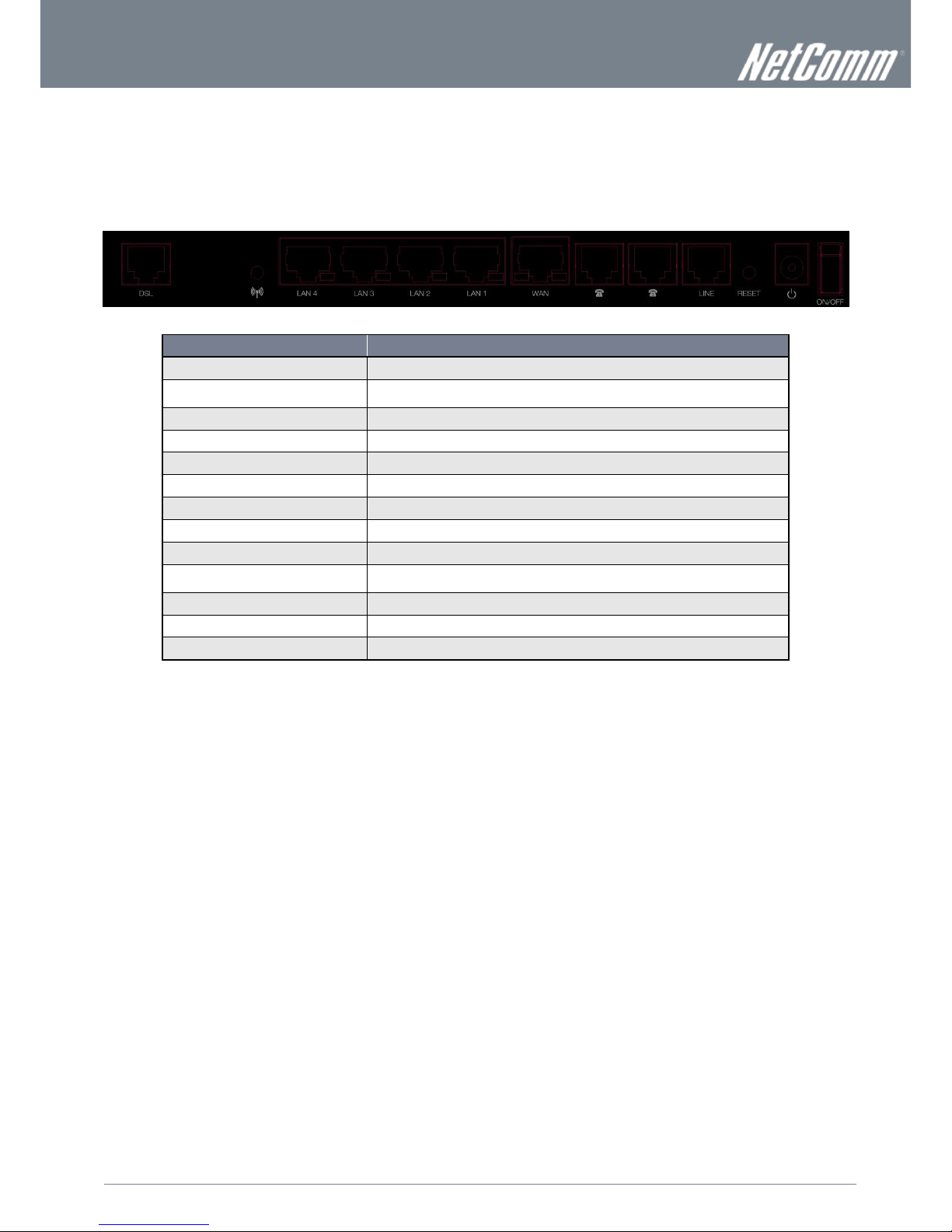
Integrated Interfaces
The following integrated interfaces are available on the rear of the NF1ADV:
Figure 1: Rear Panel
INTERFACE
FUNCTION
DSL
The ADSL port for xDSL connectivity.
WPS
Hold and release this button for less than 10 seconds to enable the WPS (WiFi Protected
System) push-button-connect function.
LAN 4
A LAN Port for wired Ethernet clients (Computers, Laptops, etc).
LAN 3
A LAN Port for wired Ethernet clients (Computers, Laptops, etc).
LAN 2
A LAN Port for wired Ethernet clients (Computers, Laptops, etc).
LAN 1
A LAN Port for wired Ethernet clients (Computers, Laptops, etc).
WAN
The WAN Ethernet port for a Fixed Line (ADSL/Cable/Satellite) connection to the internet.
Phone 1
The RJ-11 phone port provides a connection to a standard analogue telephone.
Phone 2
The RJ-11 phone port provides a connection to a standard analogue telephone
Line
The RJ-11 port provides a connection to your PSTN phone line for PSTN pass through
calling.
Reset/
Hold this button down for over 10 seconds to reset the router to factory default settings.
Power
The power connector designed for use with a DC 12V 2A Power Adapter.
On/Off
The switch that can be used to power up or down the NF1ADV.
Table 3: Rear Panel Interface Connectors
Page 9

www.netcommlimited.com
NF1ADV User Guide
9
YML38
NF1ADV Default Settings
The following tables list the default settings for the NF1ADV.
LAN (MANAGEMENT)
Static IP Address:
192.168.1.1
Subnet Mask:
255.255.255.0
Default Gateway:
192.168.1.1
Table 4 - LAN Management Default Settings
WAN (INTERNET)
WAN mode:
DHCP
Table 5 - WAN Port Default Settings
WIRELESS (WIFI)
SSID:
(Refer to the included wireless security card)
Security:
Mixed WPA2/WPA-PSK
Security Key:
(Refer to the included wireless security card)
Table 6 – WiFi Default Settings
For security purposes, each NF1ADV comes with a unique SSID that varies by a 4 digit number at the end. e.g. SSID: “NetComm Wireless XXXX”
NF1ADV WEB INTERFACE ACCESS
Username:
admin
Password:
admin
Table 7 - Web Interface Default Settings
Page 10

10
NF1ADV User Guide
www.netcommlimited.com
YML27
WiFi Data and VoIP Gateway
Safety and Product Care
With reference to unpacking, installation, use and maintenance of your electronic device, the following basic guidelines are
recommended:
To avoid fire or shock hazard do not use or install this product near water. For example, near a bathtub, kitchen sink,
laundry tub, or near a swimming pool. Also, do not expose the equipment to rain or damp areas (e.g. a wet basement).
Do not connect the power supply cord on elevated surfaces. Allow it to lie freely. There should be no obstructions in its
path and no heavy items should be placed on the cord. In addition, do not walk on, step on or mistreat the cord.
To safeguard the equipment against overheating, make sure that all openings in the unit that offer exposure to air are
unobstructed.
WARNING
Disconnect the power line from the device before servicing.
Transport and Handling
When transporting the NF1ADV, it is recommended to return the product in the original packaging. This ensures the product will not
be damaged.
In the event the product needs to be returned, ensure it is securely packaged with appropriate padding to prevent
damage during courier transport.
Page 11

www.netcommlimited.com
NF1ADV User Guide
11
YML38
Installation and Configuration of
the NF1ADV
Placement of your NF1ADV
The wireless connection between your NF1ADV and your WiFi devices will be stronger the closer your connected devices are to
your NF1ADV. Your wireless connection and performance will degrade as the distance between your NF1ADV and connected
devices increases. This may or may not be directly noticeable, and is greatly affected by the individual installation environment.
If you have concerns about your network’s performance that might be related to range or obstruction factors, try moving the
computer to a position between three to five meters from the NF1ADV in order to see if distance is the problem.
Please note: While some of the items listed below can affect network performance, they will not prohibit your wireless
network from functioning. If you are concerned that your network is not operating at its maximum effectiveness, this
checklist may help.
If you experience difficulties connecting wirelessly between your WiFi Devices and your NF1ADV, please try the following steps:
In multi-storey homes, place the NF1ADV on a floor that is as close to the centre of the home as possible. This may
mean placing the NF1ADV on an upper floor.
Try not to place the NF1ADV near a cordless telephone that operates at the same radio frequency as the NF1ADV
(2.4GHz).
Avoid obstacles and interference
Avoid placing your NF1ADV near devices that may emit radio “noise”, such as microwave ovens. Dense objects that can inhibit
wireless communication include:
Refrigerators.
Washers and/or dryers.
Metal cabinets.
Large aquariums.
Metallic-based, UV-tinted windows.
If your wireless signal seems weak in some spots, make sure that objects such as those listed above are not blocking
the signal’s path (between your wireless devices and the NF1ADV).
Cordless Phones
If the performance of your wireless network is impaired after considering the above issues, and you have a cordless phone:
Try moving cordless phones away from your NF1ADV and your wireless-enabled computers.
Unplug and remove the battery from any cordless phone that operates on the 2.4GHz band (check manufacturer’s
information). If this fixes the problem, your phone may be interfering with the NF1ADV.
If your phone supports channel selection, change the channel on the phone to the farthest channel from your wireless
network. For example, change the phone to channel 1 and move your NF1ADV to channel 11. See your phone’s user
manual for detailed instructions.
If necessary, consider switching to a 900MHz or 5GHz cordless phone.
Choose the “Quietest” Channel for your Wireless Network
In locations where homes or offices are close together, such as apartment buildings or office complexes, there may be wireless
networks nearby that can conflict with your wireless network. Use the Site Survey capabilities found in the Wireless Utility of your
wireless adapter to locate any other wireless networks that are available (see your wireless adapter’s user manual), and switch your
Router and computers to a channel as far away from other networks as possible. Alternately try using a different wireless band.
Experiment with more than one of the available channels and bands, in order to find the clearest connection and avoid interference
from neighboring cordless phones or other wireless devices.
Page 12
12
NF1ADV User Guide
www.netcommlimited.com
YML27
WiFi Data and VoIP Gateway
Hardware installation
1. Insert an Ethernet LAN cable from the WAN port of the NF1ADV to a LAN port on your modem/switch/hub.
2. For VoIP functionality, connect a standard analogue telephone to one or both of the FXS ports labelled Phone 1 or Phone 2
using the RJ-11 Cable provided.
3. For PSTN pass-through connect an RJ-11 cable from any wall jack to the FXO Line port of the NF1ADV.
4. Connect the power adapter to the Power socket on the back of the NF1ADV.
5. Plug the power adapter into the wall socket and switch on the power.
6. Wait approximately 60 seconds for the NF1ADV to power up.
Connecting via an Ethernet cable
1. Connect the Ethernet cable provided to the port marked LAN at the back of the NF1ADV.
2. Connect the other end of the yellow Ethernet cable to your computer.
3. Wait approximately 30 seconds for the connection to establish.
4. Open your Web browser and type http://192.168.1.1 into the address bar and press enter.
5. Enter “admin” (without quotations) for both the Username and Password and click on the Login button.
6. Follow the steps of the start-up wizard to set up your NF1ADV.
7. After the setup process is completed, you will be connected to the Internet.
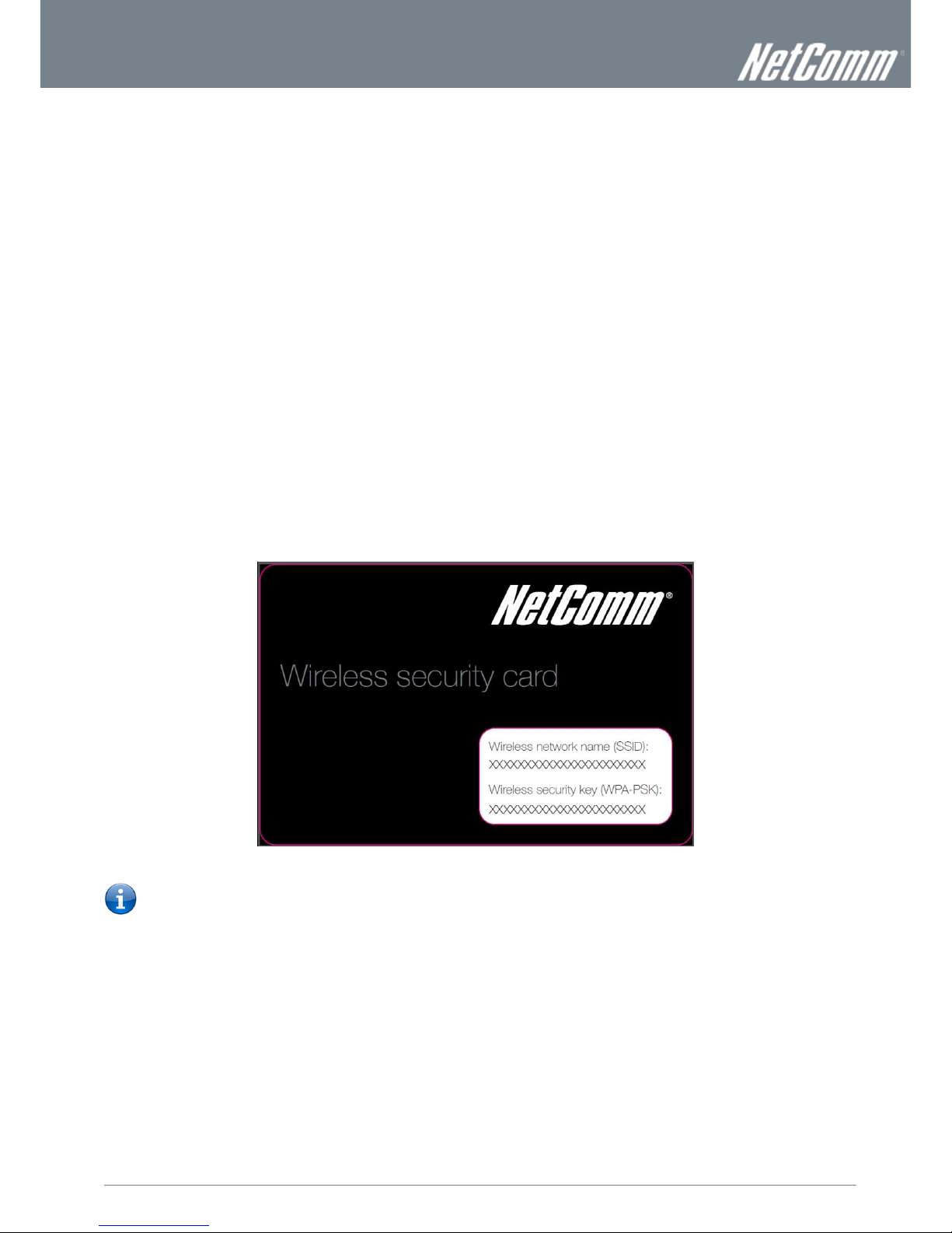
Connecting wirelessly
1. Ensure WiFi is enabled on your device (computer/laptop/Smartphone).
2. Scan for wireless networks in your area and connect to the network name that matches the Wireless network name found
on the Wireless Security Card (included in the box).
Figure 2 - Included Security Card
Please note: For security purposes, each NF1ADV has a unique SSID (such as NetComm Wireless XXXX) and Wireless
Security Key. The included Wireless Security Card lists these fields instead of the xxxxx’s as shown in the screenshot
above.
3. When prompted for your wireless security settings, enter the wireless security key listed on your Wireless Security Card.
4. Wait approximately 30 seconds for the connection to be established.
5. Open your Web browser and type http://192.168.1.1 into the address bar and press enter.
6. Enter “admin” (without quotations) as both the Username and Password and press the Login button.
7. Follow the steps to set up your NF1ADV.
8. After the setup process is completed, you will be connected to the Internet.
9. To connect additional devices via WiFi, repeat steps 1 through 4.
Page 13
www.netcommlimited.com
NF1ADV User Guide
13
YML38
Basic
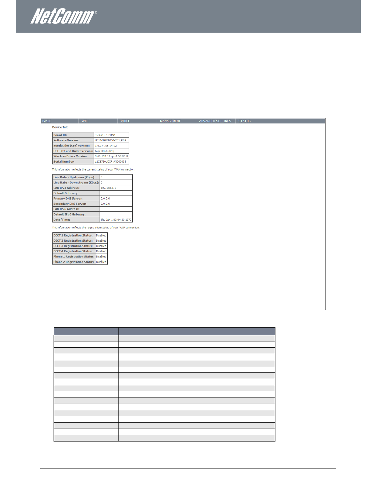
Home
The status page provides system related information and is displayed when you login to the NF1ADV console. By default, the status
page will show Device Information including hardware types and on-board software, WAN Connection status, and VoIP connection
status.
Figure 3: Basic - Home
ITEM
DEFINITION
Board ID
A unique ID assigned to the PCB (Printed Circuit Board).
Software Version
The current firmware version installed on the router.
Boot Loader (CFE) Version
The current boot loader installed on the router.
DSL PHY and Driver Version
The current line driver installed on the router.
Wireless Driver Version
The current wireless driver installed on the router.
Serial Number
The unique set of numbers assigned to the routers for identification purposes.
Line Rate – Upstream (Kbps)
The current upstream speed of the DSL connection in Kbps.
Line Rate – Downstream (Kbps)
The current upstream speed of the DSL connection in Kbps.
LAN IPv4 Address
The current version 4 IP address assigned to the router.
Default Gateway
The current default gateway of the WAN interface.
Primary DNS Server
The current primary DNS server in use
Secondary DNS Server
The current secondary DNS server is use.
LAN IPv6 Address
The current IPv6 IP address in use if assigned.
Default IPv6 Gateway
The current IPv6 default gateway if assigned.
Date/Time
The current date and time set on the router.
DECT 1-4 Registration Status
The status of the current cordless phones connected to the router.
Phone 1-2 Registration Status
The status of the current analog phones connected to the router.
Page 14

14
NF1ADV User Guide
www.netcommlimited.com
YML27
WiFi Data and VoIP Gateway
Quick Setup Configuration Wizard
When you log in to NF1ADV for the first time, you will be presented with the Home page as shown in the screenshot below. Under
the Basic menu is the Quick Setup wizard. You can use these steps to quickly configure the main functionality of the router and get
an internet connection up and running. Configuring DSL connection requires a DSL cable to be connected to the router before the
wizard can be completed. To configure quick setup please use the following steps.
1. Navigate to http://192.168.1.1 in a web browser.
Figure 4: Router Login
2. Enter “admin” for both the User name and the Password and press the OK button.
Figure 5: Basic - Quick Setup
3. Select the Quick Setup option from the Basic menu.
Figure 6: Quick Setup - Internet
4. Select the type of internet setup you wish the router to be configured with and press the Next button.
Page 15
www.netcommlimited.com
NF1ADV User Guide
15
YML38
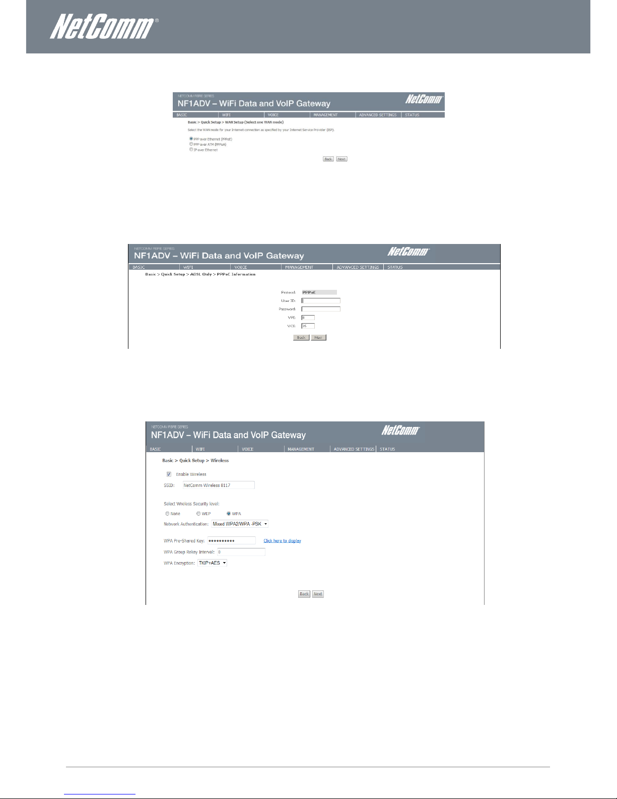
5. Select the WAN configuration for the NF1ADV to use and press the Next button.
Figure 7: Quick Setup - WAN Setup
6. For configurations using PPPoE enter the broadband username and password. For Australia users set the VPI as 8 and the
VCI as 35. For New Zealand users set the VPI as 0 and the VCI as 100. Press the Next button.
Figure 8: Quick Setup – PPPoE
7. The wireless function is set to “On” by default. Unticking the “Enable Wireless” option will disable the wireless functionality of
the NF1ADV.
Figure 9: Quick Setup – Wireless
8. To configure the NF1ADV to use wireless, customize the SSID (wireless network name) to a name of your choice. Setting a
strong wireless security level (such as WPA-PSK - AES) can prevent unauthorized access to your wireless network. Please
enter the Security Key that you wish to use, or leave this field unchanged to use the default Security Key. Click “Next” to
continue.
Page 16
16
NF1ADV User Guide
www.netcommlimited.com
YML27
WiFi Data and VoIP Gateway
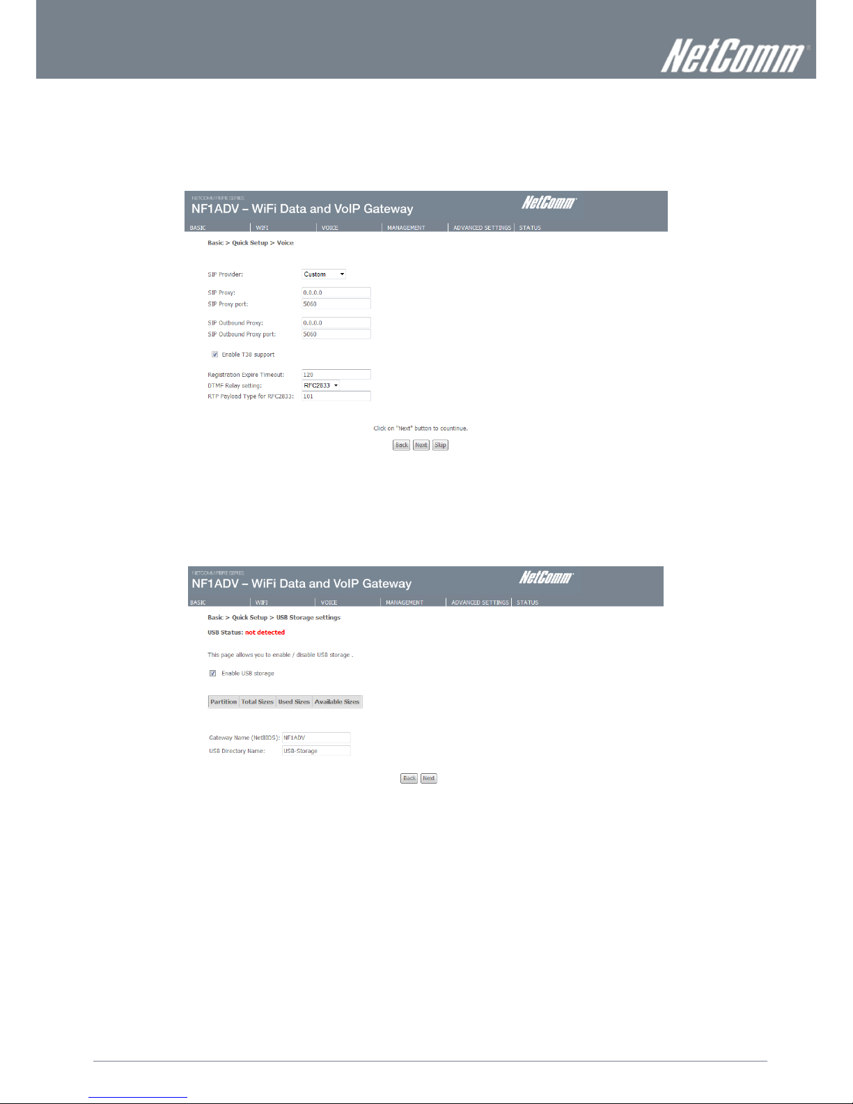
9. If you wish to use the NF1ADV for VoIP calling enter your SIP settings. You can enter your own SIP settings by selecting
custom as the SIP provider or select from a number of pre-configured SIP settings for those users with accounts with
MyNetFone, Engin, iiNet or iPrimus. Select Enable T38 support if you have a fax machine that is capable of using this
specification enabling you to send faxes via VoIP connection. If you do not wish to use the NF1ADV with VoIP press the Skip
button. When you have completed configuring this page press the Next button.
Figure 10: Quick Setup - VoIP
10. If you wish to configure the NF1ADV for USB storage select the “Enable USB Storage” option. The NetBIOS name and USB
directory name will be configured by default but can be customized here if you wish. Press the Next button when you have
completed this page.
Figure 11: Quick Setup - USB Storage
Page 17
www.netcommlimited.com
NF1ADV User Guide
17
YML38
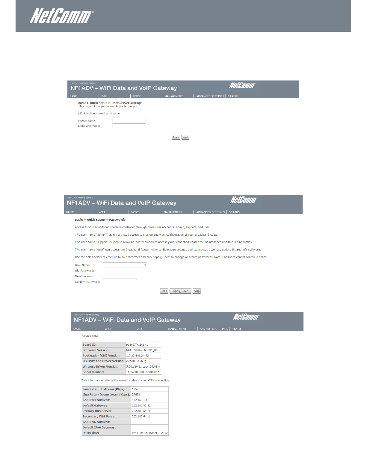
11. If you wish to configure the NF1ADV as a Print Server select the “Enable on-board print server” option and enter the printer
name and make and model into the appropriate fields. When you have completed these settings press the Next button.
Figure 12: Quick Setup - Print Server
12. The Quick Setup – Passwords page allows you to customize the username and password required to administer your
NF1ADV. It is recommended that you choose a unique password for added security. Please enter the username and
password that you wish to use, or leave these fields unchanged to use the default username and password of “admin”. Click
the “Apply/Save” button to continue or the “Skip” button to bypass making any password changes.
13. You will be directed back to the Basic – Home page.
Figure 13: Basic - Home
Page 18
18
NF1ADV User Guide
www.netcommlimited.com
YML27
WiFi Data and VoIP Gateway
WiFi
Setup
The Wireless submenu provides access to Wireless Local Area Network (WLAN) configuration settings including:
Wireless network name (SSID)
Channel restrictions (based on country)
Security
Access point or bridging behaviour
Station information
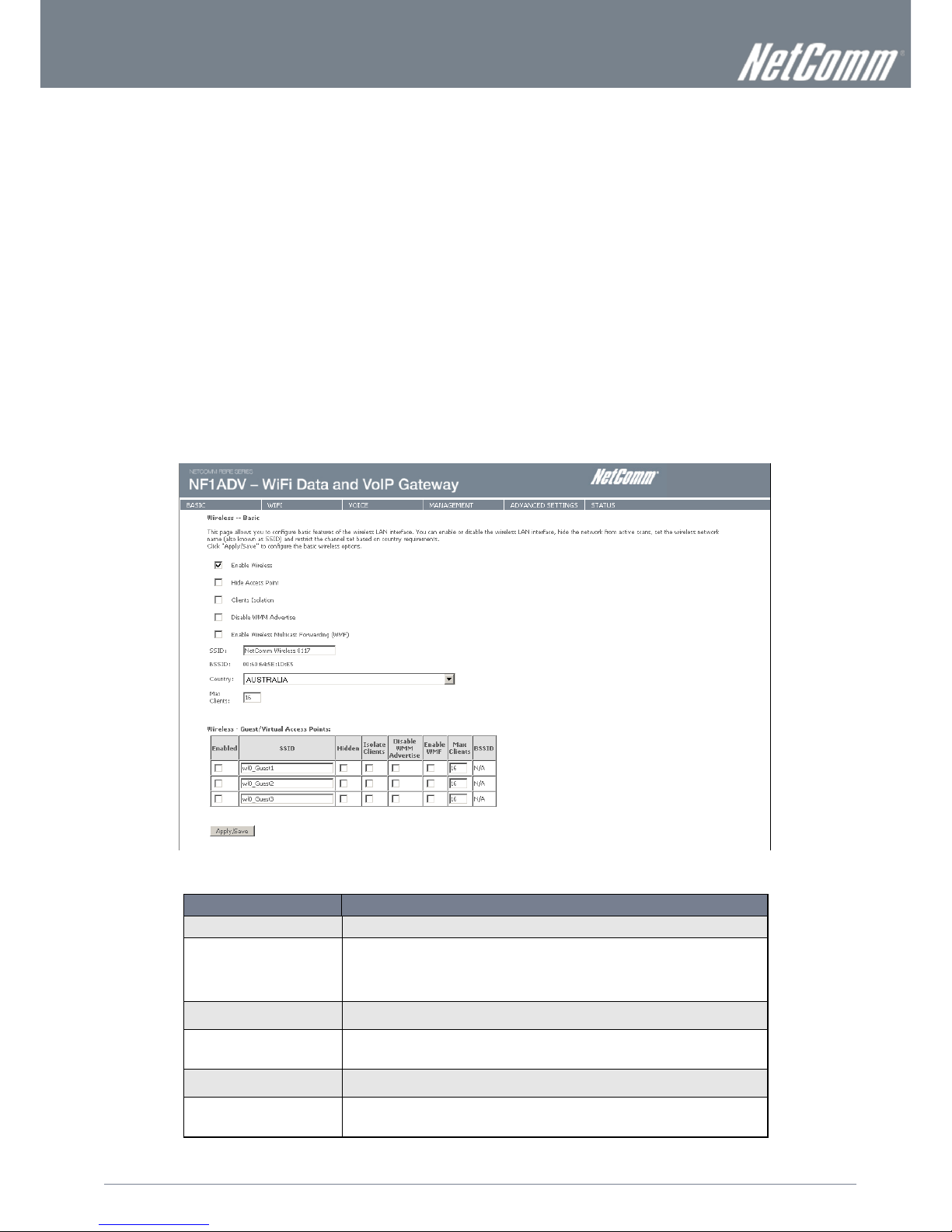
This screen allows you to configure basic features of the wireless LAN interface. You can enable or disable the wireless LAN
interface, hide the network from active scans, set the wireless network name (also known as the SSID) and restrict the channel set
based on country requirements. The Wireless Guest Network function adds extra networking security when connecting to remote
hosts.
Figure 14: Wireless - Setup
FIELD
DESCRIPTION
Enable Wireless
A checkbox that enables (default) or disables the wireless LAN interface.
Hide Access Point
Select Hide Access Point to protect the access point from detection by wireless active
scans. To check AP status in Windows, open Network Connections from the start Menu and
select View Available Network Connections. If the access point is hidden, it will not be listed
there. To connect a wireless client to a hidden access point, the user must add the access
point SSID manually to its wireless configuration.
Clients Isolation
This field stops clients PC from detecting one another in My Network Places or Network
Neighbourhood and prevents one wireless client communicating with another wireless client.
Disable WMM Advertise
This checkbox give you the option to disable WiFi Multimedia (WMM) Advertise. WMM is a
standard created to define quality of service (QoS) in WiFi networks. Do not select this option
unless your network administrator advises you to.
Enable Wireless Multicast
Forwarding (WMF)
Often used in multi-media streaming Wireless Multicast Forwarding (WMF) is a method of
sending IP datagrams to multiple receivers in a single transmission.
SSID
[1-32 characters]
SSID (Service Set Identifier) sets the wireless network name. All wireless devices attempting
to connect with the router must be configured with the correct SSID to access the WLAN. If
the SSID does not match, the wireless device will not be granted network access.
Page 19
www.netcommlimited.com
NF1ADV User Guide
19
YML38
BSSID
The BSSID is a 48bit identity used to identify a particular BSS (Basic Service Set) within an
area. In Infrastructure BSS networks, the BSSID is the MAC (Media Access Control) address
of the AP (Access Point) and in Independent BSS or ad hoc networks, the BSSID is
generated randomly.
Country
A drop-down menu that permits worldwide and specific national settings. Each country listed
enforces specific regulations limiting channel range. For Australia and New Zealand channels
are limited to numbers 1-13.
Max Clients
The maximum number of wireless clients that can be connected to the NF1ADV at any one
time.
Wireless Guest Network
The Guest SSID (Virtual Access Point) can be enabled by selecting the Enable Wireless
Guest Network checkbox. Rename the Wireless Guest Network as you wish.
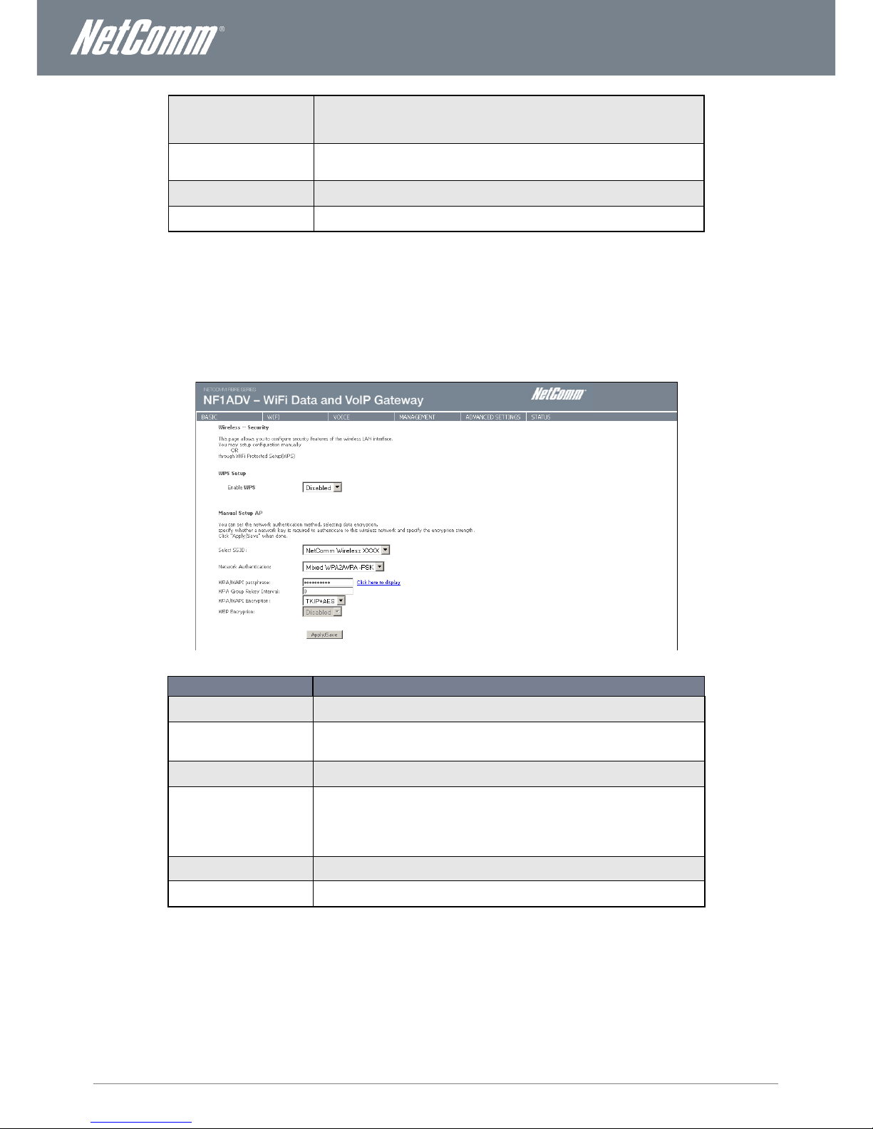
Security
Wireless Security settings are used to prevent unauthorized connections to your network. This can be as basic as a neighbouring
user who detects and is able to connect through your wireless network, right through to actual malicious interference or ‘hacking’.
Whatever the case, it is a good practice to be aware of and to use wireless network security to safeguard your data and your
network.
Figure 15: Wireless - Security
FIELD
DESCRIPTION
Select SSID
Pre- configured to the default SSID of the NetComm Wireless settings. This field can be
changed in the Wireless > Settings section.
Network Authentication
The type of wireless security you prefer to use can be set using this field.
NOTE: The wireless security types available are listed in the order of level of security from
least (top) to most (bottom).
WPA/WAP! Passphrase
The case sensitive wireless password of your choice should be at least 8 characters in length
up to a maximum of 63 characters with both numbers and letters.
WPA Group Rekey Interval
The Group Key (Group Transient Key) is a shared key among all Supplicants connected to
the same AP, and is used to secure multicast/broadcast traffic. It is not used for normal
unicast traffic. A Pairwise Transient Key secures the unicast traffic.
Group Key Renewal controls how often the Group Transient Key is changed. The Group Key
Renewal does not control the update period for the Pairwise Transient Key. The Pairwise
Transient Key is changed each time the Supplicant authenticates, or re-authenticates.
WPA/WAPI Encryption
The type of WPA encryption the wireless security will use.
WEP Encryption
The option to use WEP encryption when the network authentication is set to Open. This is a
less secure type of encryption than WPA-PSK.
Page 20

20
NF1ADV User Guide
www.netcommlimited.com
YML27
WiFi Data and VoIP Gateway
WPS
WiFi Protected Setup is a simplified method of connecting a wireless client to a wireless access point. The connection can be set
either by pressing a button or through the use of a pin number. It is designed as a quick and simple solution to setup wireless
connectivity.
Figure 16: Wireless - WPS
FIELD
DESCRIPTION
Enable WPS
Use this field to enable the WPS settings.
Add Client
Select Push-Button or PIN as the means for the wireless client to connect to the router. Then
press the “Add Enrollee” button.
Setup AP
Select Push-Button or PIN as the means for the Access Point (the router) to connect to a
wireless client. If selecting PIN mode make a note of the current PIN. Then press the “Config
AP” button.
Figure 17: Wireless - WPS Settings
Page 21
www.netcommlimited.com
NF1ADV User Guide
21
YML38
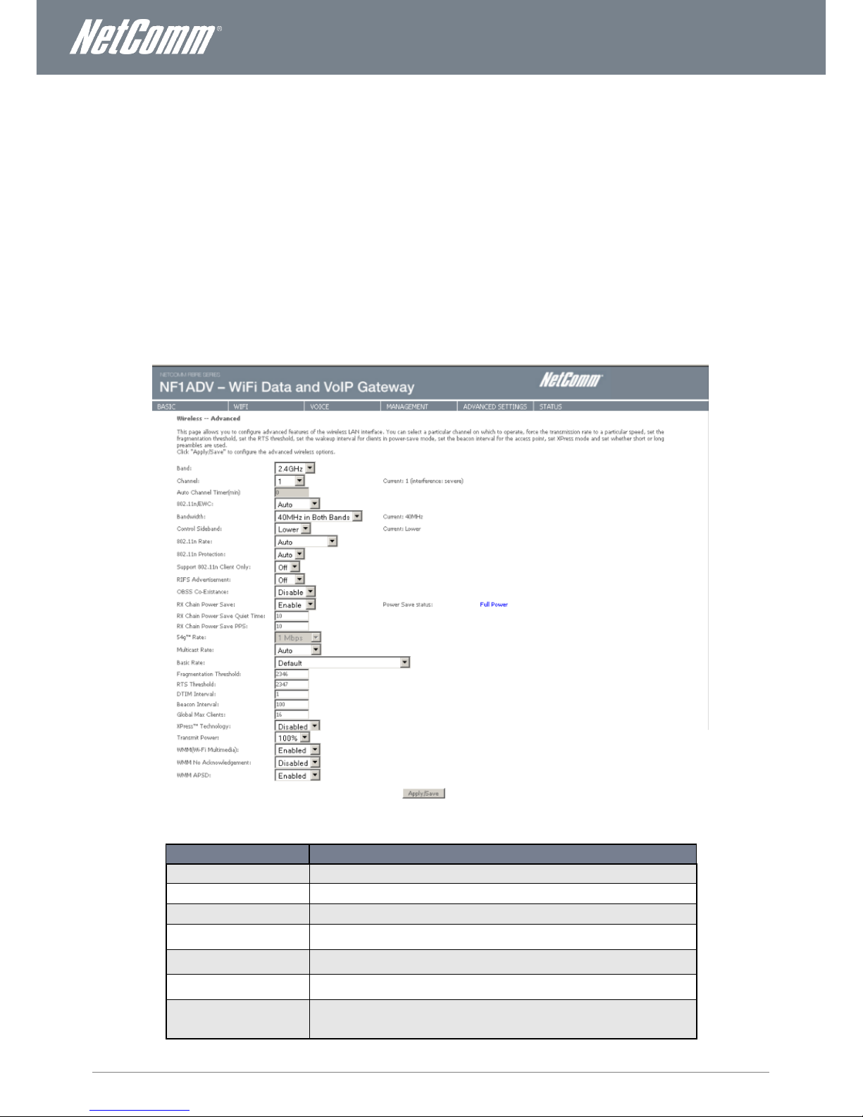
Configuration – Advanced Wireless Settings
This screen allows you to control the following advanced features of the Wireless Local Area Network (WLAN) interface:
Select the wireless channel which you wish the router to operate from.
Force the transmission rate to a particular speed.
Set the fragmentation threshold. This can be used to improve throughput in noisy or congested situations.
Set the RTS threshold. RTS stands for “Request to Send”. This parameter controls what size data packet the low
level RF protocol issues to an RTS packet. The default is 2346.
Set the wake-up interval for wireless clients using power-save mode.
Set the beacon interval for the access point.
Set Xpress mode.
Please see the Table below for an explanation of the configuration wireless settings.
Click the Apply/Save button to set any changes to the configuration settings.
Figure 18: Wireless – Advanced
FIELD
DESCRIPTION
Band
The frequency of the wireless network. 2.4GHz is standard.
Channel
Allows selection of a specific channel (1-9) or Auto mode.
Auto Channel Timer
The Auto Channel sets the length of time it takes to scan a channel in minutes.
802.11n/EWC
An equipment interoperability standard setting based on IEEE 802.11n Draft 2.0 and
Enhanced Wireless Consortium (EWC).
Bandwidth
Drop-down menu specifies the following bandwidth: 20MHz in Both Bands and 40 MHz in
Both Bands.
Control Sideband
Displays which sideband the access point is using for the control channel, either Upper or
Lower.
802.11n Rate
Drop-down menu specifies the following fixed rates. The maximum rate for bandwidth,
20MHz, is 130Mbps and the maximum bandwidth, 40MHz, is
270Mbps.
Page 22

22
NF1ADV User Guide
www.netcommlimited.com
YML27
WiFi Data and VoIP Gateway
802.11n Protection
Turn off for maximized throughput. Turn on for greater security.
Support 802.11n Client Only
The option to provide wireless Internet access only to clients who are operating at 802.11n
speeds.
RIFS Advertisement
Reduced Inter Frame Spacing (RIFS) is a required 802.11n feature that improves
performance by reducing the amount of dead time required between transmissions. We
recommend this option Off unless your network administrator advises otherwise.
OBSS Co-Existence
Overlapping Basic Service Sets (OBSS) co-existence provides a method for basic service
sets to share a single frequency.
Rx Chain Power Save
This option provides a means to save power on the receiving wireless signal.
Rx Chain Power Save Quiet
Time
The time interval before Rx Chain Power Save is implemented.
54g Rate
In Auto (default) mode, your Router uses the maximum data rate and lowers the data rate
dependent on the signal strength. The appropriate setting is dependent on signal strength.
Other rates are discrete values between 1 to 54 Mbps.
Multicast rate
Setting for multicast packet transmission rate. (1-54 Mbps).
Basic Rate
Sets basic transmission rate.
Fragmentation Threshold
A threshold (in bytes) determines whether packets will be fragmented and at what size.
Packets that exceed the fragmentation threshold of an 802.11 WLAN will be split into smaller
units suitable for the circuit size. Packets smaller than the specified fragmentation threshold
value however are not fragmented.
Values between 256 and 2346 can be entered but should remain at a default setting of 2346.
Setting the Fragmentation Threshold too low may result in poor performance.
RTS Threshold
Request To Send (RTS) specifies the packet size that exceeds the specified RTS threshold,
which then triggers the RTS/CTS mechanism. Smaller packets are sent without using
RTS/CTS. The default setting of 2347 (max length) will disables the RTS Threshold.
DTIM Interval
Delivery Traffic Indication Message (DTIM) is also known as Beacon Rate. The entry range is
a value between 1 and 65535. A DTIM is a countdown variable that informs clients of the
next window for listening to broadcast and multicast messages. When the AP has buffered
broadcast or multicast messages for associated clients, it sends the next DTIM with a DTIM
Interval value. AP Clients hear the beacons and awaken to receive the broadcast and
multicast messages. The default value is 1.
Beacon Interval
The amount of time between beacon transmissions in is milliseconds. The default is 100 ms
and the acceptable range is 1 – 65535. The beacon transmissions identify the presence of an
access point. By default, network devices passively scan all RF channels listening for
beacons coming from access points. Before a station enters power save mode, the station
needs the beacon interval to know when to wake up to receive the beacon.
Global Max Clients
Here you have the option of setting the limit of the number of clients who can connect to your
wireless network.
Xpress Technology
Broadcom’s Xpress™ Technology is compliant with draft specifications of two planned
wireless industry standards. It has been designed to improve wireless network efficiency. The
default value is disabled.
Transmit Power
The option of decreasing the transmitting power of your wireless signal
WMM (WiFi Multimedia)
WMM is a standard created to define quality of service (QoS) in WiFi networks. WMM adds
prioritized capabilities to WiFi networks and optimizes their performance when multiple
concurring applications, each with different latency and throughput requirements, compete
for network resources.
WMM No Acknowledgement
WMM No Acknowledgement gives you the option of whether to send acknowledgement
frames with WMM data packets.
WMM APSD
WMM Automatic Power Save Delivery, a feature of that allows the router to save power. This
option is enabled by default.
Table 8: Advanced - Wireless - Advanced Settings
Page 23
www.netcommlimited.com
NF1ADV User Guide
23
YML38
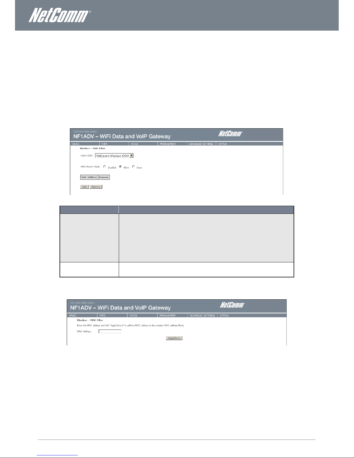
MAC Filter
This screen appears when Media Access Control (MAC) Filter is selected. This option allows access to be restricted based upon the
unique 48-bit MAC address of a wireless device’s network card.
Setting the MAC restrict mode to Allow will allow only those wireless devices listed in the MAC filter table to connect to the router.
All other wireless devices will not be able to connect via wireless to the router. Similarly, setting the MAC restrict mode to Deny will
deny only those wireless devices listed in the MAC filter table to connect to the router. All other wireless devices will be able to
connect with the router via wireless.
To add a MAC Address filter, click the Add button shown below.
To delete a filter, select it from the table below and click the Remove button.
Figure 19: Wireless - MAC Filter
FIELD
DESCRIPTION
MAC Restrict Mode
Disabled – Disables MAC filtering.
Allow – allows only those wireless devices listed in the MAC filter table to connect to the router. All other
wireless devices will not be able to connect via wireless to the router.
NOTE: Add a wireless device’s MAC address before clicking the Allow radio button or else you will
need to connect to the Router’s web user interface using the supplied yellow Ethernet cable and add
the wireless device’s MAC address.
Deny – Rejects access for the specified MAC addresses. All other wireless devices will be able to
connect to the router via wireless.
MAC Address
Lists the MAC addresses subject to the MAC Restrict Mode. The Add button prompts an entry field
that requires you type in a MAC address in a two-character, 6-byte convention: xx:xx:xx:xx:xx:xx where
xx are hexadecimal numbers. A maximum of 60 MAC addresses can be added.
Table 9: Wireless - MAC Filter Settings
Enter the MAC address on the screen below using the following format: xx:xx:xx:xx:xx:xx
Figure 20: Wireless - Add MAC Filter
Press the Apply/Save button to save the MAC address to the MAC filter list.
Page 24
24
NF1ADV User Guide
www.netcommlimited.com
YML27
WiFi Data and VoIP Gateway
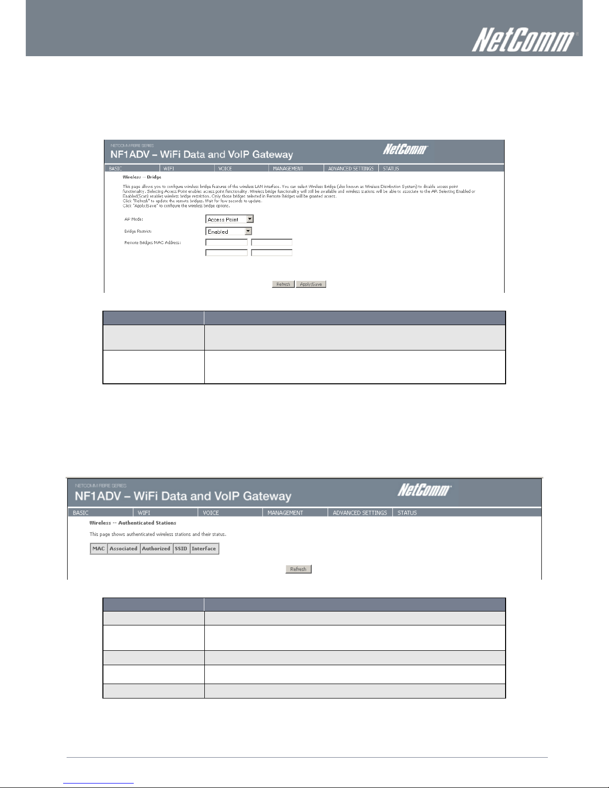
Wireless Bridge
The following screen appears when selecting Wireless Bridge, and gives a detailed explanation of how to configure wireless bridge
features for the wireless LAN interface.
Click the Apply/Save button to implement new configuration settings.
Figure 21: Wireless - Wireless Bridge
FIELD
DESCRIPTION
AP Mode
Selecting Wireless Bridge (Wireless Distribution System) disables Access Point (AP) functionality while
selecting Access Point enables AP functionality. In Access Point mode, wireless bridge functionality will
still be available and wireless stations will be able to associate to the AP.
Bridge Restrict
Selecting Disabled in Bridge Restrict disables the Wireless Bridge restriction, which means that any
wireless bridge will be granted access. Selecting Enabled or Enabled (Scan) turns the wireless bridge
restriction on. Only those bridges selected in Remote Bridges will be granted access. Click Refresh to
update the station list when Bridge Restrict is enabled.
Table 10: Wireless - Wireless Bridge
Station Info
The following screen appears when you select Station Info, and shows authenticated wireless stations and their status.
Click the Refresh button to update the list of stations in the WLAN.
Figure 22: Wireless - Station Info
FIELD
DESCRIPTION
MAC
The MAC address of any connected wireless client.
Associated
Lists all the stations that are associated with the Access Point, along with the amount of time since
packets were transferred to and from each station. If a station is idle for too long, it is removed from this
list.
Authorized
Lists those devices with authorized access.
SSID
The SSID(Service Set Identifier) of your wireless network.
Interface
The wireless interface being used to connect to the network.
Table 11: Wireless - Station Info Settings
Page 25
www.netcommlimited.com
NF1ADV User Guide
25
YML38
Voice
This section explains how to configure the VoIP settings of the NF1ADV.
SIP Basic Setting
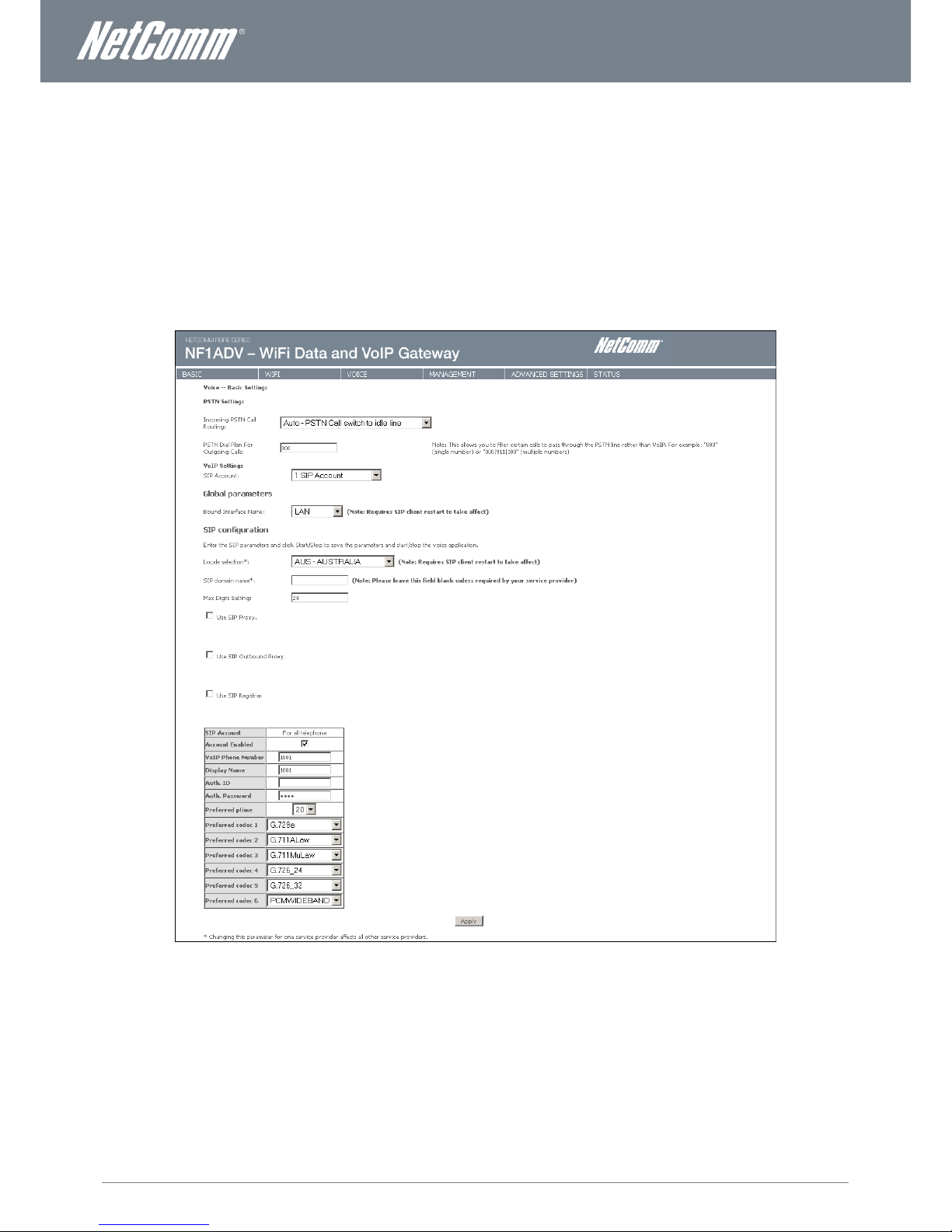
The SIP Settings page is where you enter your VOIP service settings as supplied by your VOIP service provider (VSP). If you are
unsure about a specific setting or have not been supplied information for a particular field, please contact your VOIP service provider
to verify if this setting is needed or not.
Figure 23: VoIP - SIP Basic Setting
The individual fields shown above on the SIP Basic Settings page are explained in the table (Table 12: Advanced – VoIP - SIP Basic Settings)
on the following page.
Page 26

26
NF1ADV User Guide
www.netcommlimited.com
YML27
WiFi Data and VoIP Gateway
OPTION
DEFINITION
PSTN SETTINGS
Incoming PSTN Call Routing
There are two options for how PSTN or non-VoIP calls will be routed. They are:
Auto – PSTN Call Switch to Idle Line. The PSTN call will be directed to any available handset.
Line - PSTN Call Switch to Physical Line. A small combo box appears for the router administrator
to select a handset to receive all PSTN phone calls.
PSTN Dial Plan For Outgoing
Calls
This field numbers can be entered as a prefix that will be automatically dialed before the user dials a phone
number when using the PSTN line to make a phone call. To use the PSTN line to make a phone call dial ## and
then the phone number.
VoIP SETTINGS
SIP Account
This field gives the option of selecting a single VoIP account configuration or multiple VoIP account
configurations. Please note multiple VoIP accounts can only be configured using one VoIP Service Provider.
Bound interface Name
Select the Interface that the VoIP account will use to make a connection to the VoIP Service Provider.
SIP SETTINGS
Locale Selection
The locale selection establishes the type of codec and the dial and ring tones for a given country.
SIP Domain Name
Enter the SIP domain name or IP address of your VoIP Service Provider here.
Max Digits Setting
Enter the maximum number of digits that a phone number can have.
Use SIP Proxy
Select this option if required by your VoIP Service Provider. Enter the SIP Proxy Domain Name and SIP Proxy
Port which is typically 5060.
Use SIP Outbound Proxy
Select this option if required by your VoIP Service Provider. Enter the SIP Proxy Domain Name and SIP Proxy
Port which is typically 5060.
Use SIP Registrar
Select this option if required by your VoIP Service Provider. Enter the SIP Proxy Domain Name and SIP Proxy
Port which is typically 5060.
Account Enabled
Use this option to enable or disable the VoIP account.
VoIP Phone Number
Enter the VoIP phone number as supplied to you by your VoIP Service Provider.
Display Name
Enter the Display Name as supplied to you by your VoIP Service Provider. This can be your VoIP Phone
Number.
Auth ID
Enter the Authorisation ID as supplied to you by your VoIP Service Provider.
Auth Password
Enter the Authorisation Password as supplied to you by your VoIP Service Provider.
Preferred ptime
The 'Preferred ptime' is the time delay in milliseconds between voice packets sent. You may wish to change
this setting depending on the account performance.
Preferred Codec 1 – 6
A codec is a method of compressing speech. More compression requires less
bandwidth but can sound worse. Typically, a phone will have a preferred codec, but will work with others. Use
the codec recommended by your service provider.
Table 13: Advanced – VoIP – SIP Basic Settings
After entering your VoIP settings press the Apply button. Select Management > Save/Reboot and press the Reboot button. Once
the router restarts if there is a valid internet connection and the VoIP account settings are valid the VoIP service will start.
To check if the VoIP service is working check your phone handset for a dial tone or navigate to Basic > Home and check that the
DECT and Phone registration status is displaying “Up” in the router web interface.
Page 27

www.netcommlimited.com
NF1ADV User Guide
27
YML38
SIP Advanced
The SIP Advanced page allows you to configure settings that your VoIP service provider has enabled on your SIP account and if you
have the appropriate call features and other functionality on your cordless or corded phone handsets.
Figure 24: VoIP - Advanced - Service Provider
OPTION
DEFINITION
Call Waiting
Select this option for your phone if your VoIP Service Provider has enabled Call Waiting on your SIP account.
Call Forwarding Number
Enter the phone number to be forwarded to if your VoIP Service Provider has enabled Call Waiting on your SIP
account and you wish to use this feature.
Forward Unconditionally
Select this option if your VoIP Service Provider has enabled Call Forwarding on your SIP account and you wish
to use this feature.
Forward On “Busy”
Select this option if your VoIP Service Provider has enabled Call Forwarding on your SIP account and you wish
to use this feature.
Forward On “No Answer”
Select this option if your VoIP Service Provider has enabled Call Forwarding on your SIP account and you wish
to use this feature.
MWI (Message Waiting
Indicator)
Select this option if your VoIP Service Provider has enabled MWI (Message Waiting Indicator) on your SIP
account and you wish to use this feature.
Anonymous Call Blocking
Select this option if your VoIP Service Provider has enabled Anonymous Call Blocking on your SIP account and
you wish to use this feature.
Anonymous Calling
Select this option if your VoIP Service Provider has enabled Anonymous Calling on your SIP account and you
wish to use this feature.
DND (Do Not Disturb)
Select this option if your VoIP Service Provider has enabled DND (Do Not Disturb) on your SIP account and you
wish to use this feature.
Enable T38 Support
Select this function if you wish to send or receive faxes via VoIP and have a fax machine capable of using the
T38 fax over VoIP protocol.
Interdigit Timeout
The time in seconds before which a number must be dialed or become an invalid number.
Registration Expire Timeout
The time in minutes for the SIP registered will be renewed.
Registration Retry Interval
The time in minutes before the SIP settings will attempt to be registered.
DSCP for SIP
DSCP (Differentiated Services Code Point) for SIP (Session Initiation Protocol) relates to QoS (Quality of Service)
settings. Only use this field if directed by your network administrator.
DSCP for RTP
DSCP (Differentiated Services Code Point) for RTP (Real Time Protocol) relates to QoS (Quality of Service)
settings. Only use this field if directed by your network administrator.
DTMF Relay Settings
Dual-tone Multi-frequency Relay (DTMF) is the mechanism whereby a local Voice over IP (VOIP) gateway listens
for DTMF digits (during a call), and then sends them uncompressed as either RTP or H.245 packets to the
remote VOIP gateway, which regenerates DTMF digits and prevents digit loss due to co mpression.
RTP Payload Type for
RFC2833
The Real Time Protocol Payload type for RFC2833. RFC2833 is a standards-based mechanism used to send
DTMF digits in-band (RTP) that is supported by many vendors in the industry.
Hook Flash Relay Setting
A hookflash is a brief interruption in the loop current on loopstart trunks that the attached system
does not interpret as a call disconnect. Once the PBX or PSTN senses the hookflash, it generally puts the
current call on hold and provides a secondary dial tone or access to other features such as transfer or call
waiting access.
A hookflash is done by momentarily pressing down the cradle on a telephone. Some telephone handsets have
a button called 'flash' or 'recall' that sends a 'timed loop break', or 'calibrated flash' which is a hookflash that
has a precise timing.
SIP Transport Protocol
The protocol used to transport SIP traffic. This is almost always UDP.
Enable SIP Tag Matching
Select this option to enable SIP Tag Matching.
Table 14: VoIP - Advanced - Service Provider
Page 28

28
NF1ADV User Guide
www.netcommlimited.com
YML27
WiFi Data and VoIP Gateway
SIP Debug Settings
This page allows you to set the IP address where the SIP Log data for the router VoIP account settings will be sent to and the port
number through which it will be sent.
Figure 25: VoIP - Debug Settings
OPTION
DEFINITION
SIP Log Server IP Address
Enter the IP address where the SIP Log data for the router’s currently saved VoIP account settings will be sent
to.
SIP Log Server port
Enter the port to be used for transmitting the SIP Log data for the router’s currently saved VoIP account
settings.
VoIP Module Console Log
Level
Select the type of debug messages you would like to receive. The options are:
Error. Only error messages will be logged.
Notice. Only Notice messages will be logged.
Debug. All messages will be logged.
VAD Support
Select to enable Voice Activated Dialing for a given phone handset.
Ingress Gain
The incoming signal amplitude can be controlled with this field. Combined with the Egress gai n a ratio can be
expressed of input to output. The Ingress Gain setting can help improve the quality of the VoIP line, and can
influence call volumes and help eliminate echoes.
Egress Gain
The outgoing signal amplitude can be controlled with this field. Combined with the Ingress gain a ratio can be
expressed of input to output. The Egress Gain setting can help improve the quality of the VoIP line, and can
influence call volumes and help eliminate echoes.
Table 15: VoIP - Debug Settings
Adjusting Call Quality with the Ingress/Egress Gain Settings
If your call quality is poor with heavy echo and lag times try setting the Ingress Gain value to less than 0. With less ingress the sound
volume will be lower but should reduce line echo. The optimum quality to try to attain is clarity of audio signal both incoming and
outgoing, with good call volume and little perceived echo or distortion. However the values to use will vary and are dependent on
network bandwidth, associated hardware and software codecs used.
Carry out test call trials starting with both the Ingress and Egress Gain set to about –10. Values of -1 to -11 should provide
a clear audio stream with low echo and distortion.
Continue to lower the value one setting at a time, using increments of two or three.
Make test calls until the echo is moderated.
Page 29

www.netcommlimited.com
NF1ADV User Guide
29
YML38
DECT
The NF1ADV DECT settings page displays status information and allows for DECT cordless phones to be registered to the router’s
on-board DECT base station. The NF1ADV can function as a DECT (Digital Enhanced Cordless Telecommunications) base station
for up to 4 cordless phones for both VoIP or PSTN calling.
Figure 26: VoIP – DECT
OPTION
DEFINITION
DECT – General Module Information
Module Identifier
The MAC address of the DECT base station.
Manufacturer Identifier
This is an 8 bit unique ID of the DECT base station in the form of an EMC (Equipment Manufacturer Code).
Model Identifier
This is an8 bit model ID that is unique for the DECT base station model and associated firmware version.
DECT – Base Station: Information and Action
DECT Interface Status
This field shows whether the DECT base station is enabled or disabled.
Maximum Number of
Handsets
This field shows the number of DECT cordless phones that can be connected to the DECT base station at one
time.
Currently Registered handsets
This field shows the number of DECT cordless phones that can are currently connected to the DECT base
station.
Registration Window
Use this field when registering a DECT cordless phone to the router.
Station Registration Access
Code
To set the access code, enter 4 numbers and press the Set Code button. Only DECT cordless phones that use
the correct access code can connect to the DECT base station and so use your network bandwidth. We
recommend not using the default “0000” value.
DECT – Handset: Information and Action
Handset Identifier
This field shows the DECT handset number as set in the DECT base station settings on handset was
registration.
Status
This field shows the current status of the DECT handset connection.
Subscription Time
This field shows the date and time that the DECT handset was connected.
International Portable
Equipment Identity (IPEI)
A 36 bit unique identifier of the DECT handset.
Manufacturer Identifier
This is an 8 bit unique ID of the DECT handset in the form of an EMC (Equipment Manufacturer Code).
Model Identifier
This is an8 bit model ID that is unique for the DECT handset model and associated firmware version.
Table 16: VoIP - DECT Settings
Page 30

30
NF1ADV User Guide
www.netcommlimited.com
YML27
WiFi Data and VoIP Gateway
Connecting a Cordless Phone to the DECT Base Station
1.
In the NF1ADV web interface select VOICE > DECT.
2.
Set a 4 digit Station Registration Access Code and press the Set Code button.
3.
On your DECT cordless phone navigate to the Base Registration Setting in the Advanced Settings.
4.
If prompted set the DECT phone to handset “X” where “X” is the number of DECT handsets + 1 that are already connected to
the NF1ADV DECT base station.
5.
Press the DECT button on the router for 5 seconds or press the Start Registration button in the DECT page of the NF1ADV
web interface.
6.
If the router detects the phone correctly you should now be prompted for a registration pin on the DECT handset. Enter the
Station registration Access Code you set in Step 2 into the Cordless Phone and press Ok or Apply.
7.
The cordless phone will give recognition that it is connected to the router’s DECT base station in the form of an audio beep or
test message in the handset’s interface.
8.
Press the Ping All Handsets button to verify the handset is connected to the base station. The DECT phone should produce a
series of audio sounds if the DECT phone is still communicating with the NF1ADV DECT base station.
Page 31

www.netcommlimited.com
NF1ADV User Guide
31
YML38
Management
Device Settings
The Device Settings screens allow you to back up, retrieve and restore the default settings of your Router. It also provides a function
for you to update your router’s firmware.
Backup
The following screen appears when Backup is selected. Click the Backup Settings button to save the current configuration settings.
You will be prompted for the location to save the backup file to on your PC.
Figure 27: Management - Device Settings – Backup
Update Settings
The following screen appears when selecting Update from the Device Settings submenu. By clicking on the Browse button, you can
locate a previously saved filename as the configuration backup file. Click on the Update settings button to upload the selected file.
Figure 28: Management - Device Settings - Update Settings
Restore Default
The following screen appears when selecting Restore Default from the Device Settings submenu. By clicking on the Restore Default
Settings button, you can restore your Routers default firmware settings. To restore system settings, reboot your Router.
Figure 29: Management - Device Settings - Restore Default Settings
NOTE: The Restore Default function has the same effect as the reset button. The device board hardware and the boot loader
support the reset to default button. If the reset button is continuously pushed for more than 5 seconds (and not more than
12 seconds), the boot loader will erase the configuration settings saved on flash memory.
Page 32

32
NF1ADV User Guide
www.netcommlimited.com
YML27
WiFi Data and VoIP Gateway
Update Firmware
The following screen appears when selecting the Update Firmware option from the Management > Device Settings menu. By
following this screens steps, you can update your Routers firmware. Manual device upgrades from a locally stored file can also be
performed using the following screen.
1. Obtain an updated software image file.
2. Enter the path and filename of the firmware image file in the Software File Name field or click the Browse button to locate the
image file.
3. Click the Update Software button once to upload and install the file.
Figure 30: Management - Device Settings - Update Software
SNMP
The Simple Network Management Protocol (SNMP) allows a network administrator to monitor a network by retrieving settings on
remote network devices. To do this, the administrator typically runs an SNMP management station program such as MIB browser
on a local host to obtain information from the SNMP agent, in this case the NF1ADV (if SNMP is enabled). An SNMP ‘community’
performs the function of authenticating SNMP traffic. A ‘community name’ acts as a password that is typically shared among SNMP
agents and managers.
Figure 31: Management - Device Settings – SNMP
Page 33

www.netcommlimited.com
NF1ADV User Guide
33
YML38
TR-069 Client
TR-069 enables provisioning, auto-configuration or diagnostics to be automatically performed on your router if supported by your
Internet Service Provider (ISP).
Figure 32: Management - TR-069
FIELD
DESCRIPTION
Inform
Set to enable to activate TR-069 client settings.
Inform interval
Time in seconds that data is sent to the Auto-Configuration Server (ACS).
ACS URL
The address where the ACS server is located.
ACS User Name
The user name to access the ACS server.
ACS Password
The password to access the ACS server.
WAN Interface used by TR-069
Client
The connection used to send and receive data to the ACS server.
SNTP
This interface allows you to configure the time settings of the NF1ADV.
Figure 33: Management – SNTP
FIELD
DESCRIPTION
First NTP Time Server
Select the required internet time server.
Second NTP Time Server
Select a second time server if required.
Time Zone Offset
Set the local time zone.
Table 17: Management – SNTP
NOTE: SNTP must be activated to use Parental Control.
Page 34

34
NF1ADV User Guide
www.netcommlimited.com
YML27
WiFi Data and VoIP Gateway
Access Control
The Access Control option found in the Management drop down menu configures access related parameters in the following three
areas:
Services
Passwords
Access Control is used to control local and remote management settings for your router.
Services
The Service Control List (SCL) allows you to enable or disable your Local Area Network (LAN) or Wide Area Network (WAN) services
by ticking the checkbox as illustrated below. The following access services are available: FTP, HTTP, ICMP, SNMP, SSH, TELNET,
and TFTP. Click the Apply/Save button after making any changes to continue.
Figure 34: Management - Access Control – Services
Passwords
The Passwords option configures your account access password for your Router. Access to the device is limited to the following
three user accounts:
admin is to be used for local unrestricted access control
support is to be used for remote maintenance of the device
user is to be used to view information and update device firmware
Use the fields illustrated in the screen below to change or create your password. Passwords must be 16 characters or less with no
spaces. Click the Apply/Save button after making any changes to continue.
Figure 35: Management - Access Control - Passwords
Page 35

www.netcommlimited.com
NF1ADV User Guide
35
YML38
Save/Reboot
This option saves the current configuration settings and reboots the NF1ADV router.
Figure 36: Management - Save/Reboot
NOTE 1: It may be necessary to reconfigure your TCP/IP settings to adjust for the new configuration. For example, if you disable the
Dynamic Host Configuration Protocol (DHCP) server you will need to apply Static IP settings.
NOTE 2: If you lose all access to your web user interface, simply press the reset button on the rear panel for 5-7 seconds to restore
default settings.
Page 36

36
NF1ADV User Guide
www.netcommlimited.com
YML27
WiFi Data and VoIP Gateway
Advanced Settings
Layer 2 Interface
Layer 2 refers to the data link layer of the Open Systems Interconnection model (OSI model) which provides the functional and
procedural means to transfer data between network entities and to detect and possibly correct errors that may occur in the physical
layer.
ATM Interface
The ATM interface page shows the settings of all available DSL ATM interfaces.
Figure 37: Advanced - Layer 2 Interface - A TM Interface
FIELD
DESCRIPTION
Interface
This field shows the interface name.
VPI
This field shows the Virtual Path Identifier (VPI) value. For most Australia connections the VPI is 8, for
most new Zealand connections the VPI is 0.
VCI
This field shows the Virtual Channel Identifier (VCI) value. For most Australia connections the VCI is 35,
for most new Zealand connections the VCI is 100.
DSL Latency
The value of the DSL Latency.
Category
This field shows the ATM service classes.
Link Type
This field shows the type of link in use.
Connection Mode
This field shows the selected mode of connection.
QoS
This field shows the status of the Quality of Service (QoS) function.
Remove
Select this field to remove the ATM configuration.
Figure 38: Advanced - Layer 2 Interface - A TM Interface Settings
Ethernet WAN Interface
This page allows you to configure the Ethernet WAN Interface settings.
Figure 39: Advanced - Layer 2 Interface - Ethernet WAN Interface
Page 37

www.netcommlimited.com
NF1ADV User Guide
37
YML38
WAN Service
Select WAN Service from the Advanced menu to display the status of all configured PVC(s).
A new PVC can be added or an existing entry can be edited from this page.
Figure 40: Advanced - WAN Service
FIELD
DESCRIPTION
Interface
This field shows the interface name that the PVC uses.
Description
A descriptive name assigned to the PVC.
Type
This field shows what type of connection the PVC is.
VLAN802.1p
The VLAN tag of the PVC (if applicable).
VLANMuxID
The MUX Server ID of the selected PVC.
IGMP
This field indicates whether IGMP multicast traffic is enabled or disabled for the selected PVC.
NAT
This field indicates whether Network Address Translation (NAT) is enabled or disabled.
Firewall
This field indicates whether the inbuilt firewall is enabled or disabled for the selected PVC.
IPv6
The status of Internet Protocol (IP) version 6 configuration on the WAN Service.
Mld
Multicast Listener Discovery (MLD) is a component of the Internet Protocol version 6 (IPv6) suite. MLD
is used by IPv6 routers for discovering multicast listeners on attached links, much like IGMP is used in
IPv4. The protocol is embedded in ICMPv6 instead of using a separate protocol.
PPP Manual Connection
This field advises whether the Point to Point Protocol is Manually configured.
Table 18: Advanced - WAN Service Settings
Page 38

38
NF1ADV User Guide
www.netcommlimited.com
YML27
WiFi Data and VoIP Gateway
Figure 41: Advanced - WAN Service - PPP Settings
FIELD
DESCRIPTION
PPP Username
Enter your broadband username as supplied by your Internet Service Provider (ISP) into this field.
PPP Password
Enter your broadband password as supplied by your Internet Service Provider (ISP) into this field.
Authentication Method
The type of authentication the connection uses. If you are unsure which option to use select the AUTO
option.
Interval(seconds)
Enter the interval in seconds that connection will be tested for the keep alive function.
Number of Retries
Enter the number of retries the router keep alive function will make if the connection fails.
Enable Fullcone NAT
Enable 1 to 1 mapping of an IP address and port to an internal host.
Dial on Demand (with idle
timeout timer)
With this field selected the router will Initiate an internet connection when data traffic bound for the
internet passes through the router.
PPP IP Extension
Enable PPP IP Extension for this connection (if supported by your ISP).
Enable NAT
Enable Network Address Translation (NAT) for this connection. This field is required for the DHCP
server to be configured.
Enable Firewall
Enable the inbuilt firewall for this connection.
Use Static IPv4 Address
Use a Static IP Address (as supplied by your ISP) for this connection.
MTU
Set the MTU (Maximum Transmit Unit) size.
Enable PPP Manual Mode
Use this field to configure and initiate a PPP connection manually.
Enable PPP Debug Mode
Enable extended PPP logging for this connection.
Enable IGMP Multicast Proxy
Enable IPV6 IGMP Multicast support for the WAN service.
Page 39

www.netcommlimited.com
NF1ADV User Guide
39
YML38
LAN
This screen allows you to configure the Local Area Network (LAN) interface on your router.
Figure 42: Advanced – LAN
See the field descriptions below for more details.
FIELD
DESCRIPTION
Group Name
Select the Group Name if configured.
IP Address
The IP address of the LAN interface.
Subnet Mask
Enter the subnet mask for the LAN interface.
Enable IGMP Snooping
Enable by ticking the box.
Standard Mode: In standard mode multicast traffic will broadcast to all bridge ports when no client
subscribes to a multicast group.
Blocking Mode: In blocking mode, the multicast data traffic will be blocked. When there are no client
subscriptions to a multicast group, it will not broadcast to the bridge ports.
Disable DHCP Server
This option disables the DHCP server and should only be selected when using a Static IP address.
Enable DHCP Server
On selecting this field enter the start IP address and the end IP address as well as the lease time. With
the DHCP server enabled the router automatically assigns the IP address, subnet mask, default
gateway and DNS server addresses to all DHCP clients connecting to the router.
Configure the Second IP
Address and Subnet Mask for
LAN interface
Use this option to configure a second IP address for a second LAN interface. Enter the IP address and
subnet mask of the secondary LAN connection.
Page 40

40
NF1ADV User Guide
www.netcommlimited.com
YML27
WiFi Data and VoIP Gateway
IPv6 LAN Auto Configuration
This page can be used to configure the router for IPv6 use.
Figure 43: Advanced - IPv6
OPTION
DEFINITION
LAN IPv6 Link-Local Address
Configuration
EUI-64 – A 64-bit Global Identifier (EUI-64™) standard for use with the IPv6 Protocol.
User Setting – User defined IPv6 Address
Static LAN IPv6 Address
Configuration
Enter a static IPv6 address for the router if one has been assigned to you by your Internet Service Provider.
IPv6 LAN Application
Enable IPv6 DHCP server
Stateless address
autoconfiguration
IPv6 hosts can configure themselves automatically when connected to a routed IPv6 network using Internet
Control Message Protocol version 6 (ICMPv6) router discovery messages. This type of configuration is suitable
for small organizations and individuals. It allows each host to determine its address from the contents of
received user advertisements. It makes use of the IEEE EUI-64 standard to define the network ID portion of the
address.
Stateful Address Configuration
This configuration requires some human intervention as it makes use of the Dynamic Host Configuration
Protocol for IPv6 (DHCPv6) for installation and administration of nodes over a network. The DHCPv6 server
maintains a list of nodes and the information about their state to know the availability of each IP address from
the range specified by the network administrator.
Enable RADVD
The Router Advertisement Daemon (radvd) is an open-source software product that implements link-local
advertisements of IPv6 router addresses and IPv6 routing prefixes using the Neighbor Discovery Protocol (NDP)
as specified in RFC 2461. The Router Advertisement Daemon is used by system administrators in stateless
auto-configuration methods of network hosts on Internet Protocol version 6 networks.
When IPv6 hosts configure their network interfaces, they broadcast router solicitation (RS) requests onto the
network to discover available routers. The radvd software answers requests with router advertisement (RA)
messages. In addition, radvd periodically broadcasts RA packets to the attached link to update network hosts.
The router advertisement messages contain the routing prefix used on the link, the link maximum transmission
unit (MTU), and the address of the responsible default router.
Table 19 Advanced - IPv6 Configuration Settings:
Page 41

www.netcommlimited.com
NF1ADV User Guide
41
YML38
NAT
Network address translation (NAT) is the process of modifying IP address information in IP packet headers while in transit through
the router.
Port Forwarding
Port Forwarding allows you to direct incoming traffic from the Internet side (identified by Protocol and External port) to the internal
server with a private IP address on the LAN side. The Internal port is required only if the external port needs to be converted to a
different port number used by the server on the LAN side. A maximum of 32 entries can be configured.
Figure 44: Advanced - NAT - Virtual Server
To add a Virtual Server, click the Add button. The following screen will display.
Figure 45: Advanced - NAT - Add Virtual Server
FIELD
DESCRIPTION
Select a Service or custom
Server
Select a pre-configured port forwarding rule or choose custom server to create your own port
forwarding rule.
Server IP Address
Enter the IP address of the local server.
External Port Start
Enter the starting external port number (when custom server is selected). When a service is connected
this field will be completed automatically.
External Port End
Enter the ending external port number (when custom server is selected). When a service is connected
this field will be completed automatically.
Protocol
Options include TCP, UDP or TCP/UDP.
Internal Port Start
Enter the starting internal port number (when custom server is selected). When a service is connected
this field will be completed automatically.
Internal Port End
Enter the ending internal port number (when custom server is selected). When a service is connected
this field will be completed automatically.
Table 20: Advanced - NAT - Add Virtual Server Settings
Page 42

42
NF1ADV User Guide
www.netcommlimited.com
YML27
WiFi Data and VoIP Gateway
Port Triggering
Some applications require specific ports in the Router’s firewall to be open for access by remote parties. Port Triggering opens up
the ‘Open Ports’ in the firewall when an application on the LAN initiates a TCP/UDP connection to a remote party using the
‘Triggering Ports’.
The Router allows the remote party from the WAN side to establish new connections back to the application on the LAN side using
the ‘Open Ports’. A maximum 32 entries can be configured.
Figure 46: Advanced - NAT - Port Triggering Setup
To add a Trigger Port, press the Add button. The following screen will be displayed.
Figure 47: Advanced - NAT - Add Port Trigger
FIELD
DESCRIPTION
Select an Application or Custom
Application
A user can select a pre-configured application from the list or select the Custom Application option to
create custom application settings.
Trigger Port Start
Enter the starting trigger port number (when you select Custom Application). When an application is
selected the port range values are automatically entered.
Trigger Port End
Enter the ending trigger port number (when you select Custom Application). When an application is
selected the port range values are automatically entered.
Trigger Protocol
Options include TCP, UDP or TCP/UDP.
Open Port Start
Enter the starting open port number (when you select Custom Application). When an application is
selected the port range values are automatically entered.
Open Port End
Enter the ending open port number (when you select Custom Application). When an application is
selected the port range values are automatically entered.
Open Protocol
Options include TCP, UDP or TCP/UDP.
Page 43

www.netcommlimited.com
NF1ADV User Guide
43
YML38
DMZ Host
The NF1ADV will forward IP packets from the Wide Area Network (WAN) that do not belong to any of the applications configured in
the Virtual Servers table to the DMZ host computer.
Enter the computer’s IP address and click Apply to activate the DMZ host. To deactivate the DMZ Host function clear the IP
address field and press the Save/Apply button.
Figure 48: Advanced - NAT - DMZ Host
IP Address Mapping
This feature allows the one or many LAN devices to be mapped to one or many WAN IP addresses.
Figure 49: Advanced - NAT - IP Address Mapping
OPTION
DEFINITION
Select a Service
Options include: One to One, Many to One, Many to Many(overload), Many to Many(no overload)
Local Start IP
The start IP address of a local IP address range.
Local End IP
The end IP address of a local IP address range. If you wish to use a single local IP address only, enter the same
IP address as the Local Start IP field into this field.
Public Start IP
The start IP address of a public/WAN IP address range.
Public End IP
The send IP address of a public/WAN IP address range. If you wish to use a single public IP address, enter the
same IP address as the Local Start IP field into this field.
Figure 50: Advanced - NAT - IP Address Mapping Settings
Page 44

44
NF1ADV User Guide
www.netcommlimited.com
YML27
WiFi Data and VoIP Gateway
Security
IP Filtering
The IP Filtering function sets filter rules that limit incoming and outgoing IP traffic. Multiple filter rules can be set with at least one
limiting condition. All conditions must be fulfilled for individual IP packets to pass through the filter.
Outgoing IP Filter
The default setting for Outgoing traffic is ACCEPTED. Under this condition, all outgoing IP packets that match the filter rules will be
BLOCKED.
Figure 51: Advanced - Security - IP Filter – Outgoing
To add an outgoing IP filtering rule, click the Add button. The following screen will be displayed.
Figure 52: Advanced - Security - IP Filter - A dd Outgoing
FIELD
DESCRIPTION
Filter Name
The filter rule descriptive name.
IP Version
Select the IP Address protocol (IPv4 or IPv6).
Protocol
Options include TCP, UDP, TCP/UDP or ICMP Source IP Address.
Source IP Address
Enter the local source IP address from where the data originates.
Source Port (port or port:port)
Enter the source port number or port range for the filter rule.
Destination IP Address
Enter the destination IP address.
Destination Port (port or
port:port)
Enter the destination port number or port range for the filter rule.
Table 21: Advanced - Security - IP Filter - Add Outgoing IP Filter Settings
Page 45

www.netcommlimited.com
NF1ADV User Guide
45
YML38
Incoming IP Filter
The default setting for all Incoming traffic is BLOCKED. Under this condition only those incoming IP packets that match the filter
rules will be ACCEPTED.
Figure 53: Advanced – Security – IP Filter – Incoming
To add an incoming IP filtering rule, click the Add button. The following screen will display.
Figure 54: Advanced - Security - IP Filter - A dd Incoming IP Filter
Please refer to the Outgoing IP Filter table for field descriptions.
Click the Apply/Save button to save and activate the filter.
Page 46

46
NF1ADV User Guide
www.netcommlimited.com
YML27
WiFi Data and VoIP Gateway
Parental Control
The Parental Control feature allows you to take advanced measures to ensure the computers connected to the LAN are used only
when and how you decide.
Time Restriction
This Parental Control function allows you to restrict access from a Local Area Network (LAN) connected device to an outside
network through the router on selected days and at certain times. Make sure to activate the Internet Time server synchronization as
described in the SNTP section, so that the scheduled times match your local time.
Figure 55: Advanced - Parental Control – Time Restriction
To add a time restriction rule press the Add button. The following screen will appear.
Figure 56: Advanced - Parental Control - Ad d Time Restriction
See the instructions below. Press the Apply/Save button to save a time restriction rule.
FIELD
DESCRIPTION
Rule Name
A user defined name for the time restriction rule.
Browser’s MAC Address
The MAC address of the network card of the computer running the browser.
Other MAC Address
The MAC address of a second LAN device or network card.
Days of the Week
The days of the week for which the rules apply.
Start Blocking Time
The time of day when the restriction starts.
End blocking time
The time of day when the restriction ends.
Table 22: Advanced - Parental Control - Add Time Restriction Settings
Page 47

www.netcommlimited.com
NF1ADV User Guide
47
YML38
URL Filter
With the URL filter, you are able to add certain websites or URLs to a safe or blocked list. This will provide you added security to
ensure any website you deem unsuitable will not be able to be seen by anyone who is accessing the Internet via the NF1ADV.
Select the ‘To block’ or ‘To allow’ option and then click Add to enter the URL you wish to add to the URL Filter list.
Figure 57: Advanced - Parental Control - URL Filter
Once you have chosen to add a URL to the list you will be prompted to enter the address. Simply type it in and select the
Apply/Save button.
Figure 58: Advanced - Parental Control - Ad d URL Filter
Page 48

48
NF1ADV User Guide
www.netcommlimited.com
YML27
WiFi Data and VoIP Gateway
Quality of Service
Quality of Service offers a defined level of performance in a data communications system - for example the ability to guarantee that
video traffic is given priority over other network traffic to ensure that video streaming is not disrupted by other network requirements.
This means that should you be streaming video and someone else in the house starts downloading a large file, the download won’t
disrupt the flow of video data.
Figure 59: Advanced - Enable QoS
To enable QoS select the Enable QoS checkbox, and set the Default DSCP (Differentiated Services Code Point) Mark. Then press
the Apply/Save button.
Queue Setup
Figure 60: Advanced - QoS Queue Setup
Click the Add button to add a QoS Queue. The following screen will be displayed.
Figure 61: Advanced - QoS - Add QoS Queue
The above screen allows you to configure a QoS queue entry and assign it to a specific network interface. Each of the queues can
be configured for a specific precedence. The queue entry configured here will be used by the classifier to place ingress packets
appropriately.
NOTE: Precedence level 1 relates to higher priority while precedence level 3 relates to lower priority.
Page 49

www.netcommlimited.com
NF1ADV User Guide
49
YML38
QoS Classification
Figure 62: Advanced - QoS Classification Setup
Click the Add button to configure network traffic classes.
Figure 63: Advanced - Add QoS Network Traffic Classification
The above screen creates a traffic class rule to classify the upstream traffic, assign queuing priority and optionally overwrite the IP
header TOS (type of service) byte. A rule consists of a class name and at least one condition. All of the specified conditions in this
classification rule must be satisfied for the rule to take effect.
Click the Apply/Save button to save and activate the rule.
Page 50

50
NF1ADV User Guide
www.netcommlimited.com
YML27
WiFi Data and VoIP Gateway
Routing
The Default Gateway, Static Route, Policy Routing and Dynamic Route settings can be found in the Routing option of the Advanced
menu.
Default Gateway
Select your preferred WAN interface from the available options.
Figure 64: Advanced - Routing - Default Gateway
Static Route
The Static Route screen displays the configured static routes. Click the Add or Remove buttons to change settings.
Figure 65: Advanced - Routing - Static Route
To add a static route rule click the Add button. The following screen will be displayed.
Figure 66: Advanced - Routing - Add Static Route
Enter the Destination Network Address, Subnet Mask, Gateway IP Address and/or WAN Interface. Then click Apply/Save to add
the entry to the routing table.
Page 51

www.netcommlimited.com
NF1ADV User Guide
51
YML38
Policy Routing
This function allows you to add policy rules to certain situations.
Figure 67: Advanced - Routing - Policy Routing
Click the Add button to add a policy rule. The following screen will be displayed.
Figure 68: Advanced - Routing - Add Policy Route
Enter a, select the LAN port to be used, enter the source IP address
FIELD
DESCRIPTION
Policy Name
A user defined name for the policy route.
Physical LAN Port
The LAN port to be used for the policy.
Source IP
The IP address of the LAN device involved with the policy.
Use Interface
Select the Interface that the policy will employ.
Gateway
Enter the gateway address.
RIP (Routing Information Protocol)
To activate this option, select the Enabled checkbox.
To configure an individual interface, select the desired RIP version and operation, and enter a check in the Enabled checkbox for
that interface. Click Apply/Save to save the configuration.
Figure 69: Advanced - Routing - RIP
Page 52

52
NF1ADV User Guide
www.netcommlimited.com
YML27
WiFi Data and VoIP Gateway
DNS
DNS Server
This page allows the user to enable automatic DNS settings detected from the Internet Service Provider or specify their own DNS
server address manually.
Figure 70: Advanced - DNS Server
Dynamic DNS
The Dynamic DNS service allows a dynamic IP address to be aliased to a static hostname in any of a selection of domains, allowing
the router to be more easily accessed from various locations on the internet.
Figure 71: Advanced - DNS - Dynamic DNS
Note: The Add/Remove buttons will be displayed only if the router has been assigned an IP address from the remote server.
To add a dynamic DNS service, click the Add button and the following screen will display.
Figure 72: Advanced - DNS - Add Dynamic DNS Account
Page 53

www.netcommlimited.com
NF1ADV User Guide
53
YML38
FIELD
DESCRIPTION
D-DNS Provider
Select the dynamic DNS provider from the list.
Host Name
The name of the dynamic DNS provider.
Interface
Select the interface from the list.
Username
Enter the Dynamic DNS account username.
Password
Enter the Dynamic DNS account password.
Table 23: Advanced - DNS - Add Dynamic DNS Account Settings
DSL
This page allows the user to modify the DSL modulation settings on the unit. By changing the settings, the user can specify which
DSL modulation that the modem will use.
Figure 73: Advanced – DSL
For advanced DSL options press the Advanced Settings button.
Figure 74: Advanced - DSL - Advanced DSL Settings
The DSL advanced settings relate to test mode settings. The default selection is ‘Normal’.
ADSL Tone Settings
For ADSL Tone Settings select the ‘Tone Selection’ button on the DSL Advanced Settings page.
The frequency band of ADSL is split up into 256 separate tones, each spaced 4.3125kHz apart. With each tone carrying separate
data, the technique operates as if 256 separate routers were running in parallel. The tone range is from 0 to 31 for upstream traffic
and from 32 to 255 for downstream traffic. Do not change these settings unless you are directed by your Internet Service Provider.
Page 54

54
NF1ADV User Guide
www.netcommlimited.com
YML27
WiFi Data and VoIP Gateway
Figure 75: Advanced - DSL - ADSL Tone Settings
UPnP
Universal Plug and Play (UPnP) is a set of networking protocols that can allow networked devices, such as computers, printers, WiFi
access points and mobile phones to automatically detect each other's presence on the network and establish functional network
services for data sharing, communications, and entertainment.
Figure 76: Advanced – UPnP
DNS Proxy
To enable DNS Proxy settings, tick the corresponding checkbox and then enter host and Domain name, as in the example shown
below. Click Apply/Save to continue.
Figure 77: Advanced - DNS Proxy
The Host Name and Domain name are combined to form a unique label that is mapped to the router IP address. This can be used
to access the user interface of the router with a local name rather than by using the router IP address.
Page 55

www.netcommlimited.com
NF1ADV User Guide
55
YML38
Print Server
This page allows you to enable or disable the USB port of the NF1ADV to be used as a print server.
Please see Appendix B for more details on setting up your router to work with Print Server functionality.
Figure 78: Advanced - Print Server
Storage Service
This page allows you to enable or disable the USB ports of the NF1ADV so it can be used as a mass storage server.
Please see Appendix C for more details on setting up your router to work with Storage Server functionality.
Figure 79: Advanced - USB Storage
Interface Grouping
Interface grouping supports multiple ports to PVC and bridge groups. Each group performs as an independent network. To use this
feature, you must create mapping groups with appropriate LAN and WA N interfaces using the Add button.
The Remove button removes mapping groups, returning the ungrouped interfaces to the default group. Only the default group has
an IP interface.
Figure 80: Advanced - Interface Grouping
Page 56

56
NF1ADV User Guide
www.netcommlimited.com
YML27
WiFi Data and VoIP Gateway
To add an Interface Group, click the Add button. The following screen will appear. It lists the available and grouped interfaces.
Follow the instructions shown below:
Figure 81: Advanced - Add Interface Grouping
Automatically Add Clients with the following DHCP Vendor IDs
Add support to automatically map LAN interfaces to PVC’s using DHCP vendor ID (option 60). The local DHCP server will decline
and send the requests to a remote DHCP server by mapping the appropriate LAN interface. This will be turned on when Interface
Grouping is enabled.
Press the Apply/Save button to save any changes to the configuration settings.
Multicast – IGMP Configuration
The Internet Group Management Protocol (IGMP) is a communications protocol used by hosts and adjacent routers on IP networks
to establish multicast group memberships. IGMP is a protocol only used on the network between a host and the router. It allows a
host to inform the router whenever that host needs to join or leave a particular multicast group. IGMP provides for more efficient
allocation of resources when used with online gaming and video streaming.
Figure 82: Advanced - IGMP Configuration
Page 57

www.netcommlimited.com
NF1ADV User Guide
57
YML38
FIELD
DEFINITION
Default Version
The version IGMP in use by the router.
Query Interval
The hosts on the segment report their group membership in response to the router’s queries. The query interval
timer is also used to define the amount of time a router will store particular IGMP state if it does not hear any
reports on the group. The query interval is the time in seconds between queries sent from the router to IGMP
hosts.
Query Response Interval
When a host receives the query packet, it starts counting to a random value, less the maximum response time.
When this timer expires, the host replies with a report, provided that no other host has responded yet. This
accomplishes two purposes:
a) Allows controlling the amount of IGMP reports sent during a time window.
b) Engages the report suppression feature, which permits a host to suppress its own report and conserve
bandwidth.
Last Member Query Interval
IGMP uses this value when router hears IGMP Leave report. This means that at least one host wants to leave
the group. After router receives the Leave report, it checks that the interface is not configured for IGMP
Immediate Leave (single-host on the segment) and if not, it sends out an out-of-sequence query.
Robustness Value
The robustness variable is a way of indicating how susceptible the subnet is to lost packets. IGMP can recover
from robustness variable minus 1 lost IGMP packets. You can also click the scroll arrows to select a new
setting. The robustness variable should be set to a value of 2 or greater. The default robustness variable value
is 2.
Maximum Multicast Groups
The maximum number of multicast groups that the router can control at any one time.
Maximum Multicast Data
Sources
The maximum number of data sources a multicast group can have.
Maximum Multicast Group
Members
The maximum number of hosts a multicast group can have.
Fast Leave Enable
With IGMP fast-leave processing, which means that the router immediately removes the interface attached to a
receiver upon receiving a Leave Group message from a IGMP host.
LAN to LAN (Intra LAN)
multicast
Multicasting across a LAN is enabled.
SIP ALG
The SIP Application Layer Gateway (ALG) provides functionality to allow VoIP traffic to pass both from the private to public and
public to private side of the firewall when using Network Address and Port Translation (NAPT). SIP ALG inspects and modifies SIP
traffic to allow SIP traffic to pass through the firewall.
Figure 83: Advanced - SIP ALG
Page 58

58
NF1ADV User Guide
www.netcommlimited.com
YML27
WiFi Data and VoIP Gateway
Status
The Status menu has the following submenus:
Diagnostics
WAN
System Log
Statistics
Route
ARP
DHCP
Diagnostics
The Diagnostics menu provides feedback on the connection status of the device. The individual tests are listed below. If a test
displays a fail status:
1. Click on the Help link and follow the troubleshooting procedures in the Help screen that appears.
2. Now click Re-run Diagnostic Tests at the bottom of the screen to re-test and confirm the error
3. If the test continues to fail, contact Technical Support.
Figure 84: Status – Diagnostics
FIELD
DESCRIPTION
ENET Connection
Pass: Indicates the Ethernet connection to your computer is connected to the LAN port of the router.
Fail: Indicates that the router does not detect the Ethernet interface of your computer.
Test your Wireless Connection
Pass: Indicates that the wireless card is switched ON.
Fail: Indicates that the wireless card is switched OFF.
Test the Assigned IP Address
Pass: Indicates that the modem has received a valid IP address from the PPP server.
Fail: Indicates that the modem has not received a valid IP address from the PPP server.
Ping Primary Domain Name Server
Pass: Indicates that the router can communicate with the DNS server.
Fail: Indicates that the router was unable to communicate with the primary Domain Name Server (DNS).
This may not have an effect on your internet connection. Therefore if this test fails but you are still able
to connect to the internet there is no need to troubleshoot this issue.
Page 59

www.netcommlimited.com
NF1ADV User Guide
59
YML38
WAN
The WAN page details the configuration of the router’s WAN connections.
Figure 85: Status - WAN
FIELD
DESCRIPTION
Interface
The Interface of the WAN connection.
Description
The description of the WAN connection.
Type
The type of WAN connection.
VLAN MuxId
Details the status of VLAN MuxId if used.
IPv6
Details whether IPv6 is used or not with the WAN connection.
IGMP
Details the status of IGMP on each WAN connection. IGMP is only used with IP v4 connections.
MLD
Details whether Multicast Listener Discovery (MLD) protocol, the IPv6 variant of IGMP is enabled.
NAT
The NAT status of the WAN connection.
Firewall
The status of the router firewall across the WAN connection.
Status
The status of the WAN connection.
IPv4 Address
The current IP v4 address of the WAN connection.
PPP Manual Connection
This field advises if the WAN connection is configured as a PPP Manual Connection.
Page 60

60
NF1ADV User Guide
www.netcommlimited.com
YML27
WiFi Data and VoIP Gateway
System Log
This function allows you to view system events and configure related options. Follow the steps below to enable and view the
System Log.
1. Click Configure System Log to continue.
Figure 86: Status - System Log
2. Select the system log options (see table below) and click the Apply/Save button.
Figure 87: Status - Configure System Log
FIELD
DESCRIPTION
Log
Indicates whether the system is currently recording events. System logging can be disabled or enabled.
By default system logging is disabled.
Log Level
Allows you to configure the event level and filter out unwanted events below this level. The events range
from the highest level “Emergency” down to the lowest “Debugging” level and are stored in the router’s
SDRAM memory. When the log buffer is full the newest event will wrap up to the top of the log buffer
and overwrite the lowest event. By default the log level is “Debugging” which is the lowest critical level.
The log levels are defined as follows:
Emergency is the most serious event level whereas debugging is the least important. For instance if the
log level is set to debugging, all the events from the lowest debugging to the highest Emergency level
will be recorded. If the log level is set to Error level only error level logs will be able to be viewed.
Display
Allows you to select the log events and displays in the View System Log window. For events from
debugging level and above to the highest Emergency level.
Level
Allows you to select the logged events and display in the View system Log window, per log level.
Mode
Allows you to specify whether events should be stored in local memory, be sent to a remote system log
server or both simultaneously.
If remote mode is selected the view system log windows will not be able to display events saved to the
remote system log server. When either Remote mode or both mode are selected you will be prompted
for the system log server IP address and UDP port.
Table 24: Status - Configure System Log Settings
Page 61

www.netcommlimited.com
NF1ADV User Guide
61
YML38
Statistics
These screens provide detailed information for:
Local Area Network (LAN),
Wide Area Network (WAN) Service,
xTM
xDSL Service
NOTE: These statistics pages refresh every 15 seconds.
LAN
This screen displays statistics for the Ethernet and Wireless LAN interfaces.
Figure 88: Status – LAN
INTERFACE
DESCRIPTION
Received/Transmitted
Bytes
Rx/Tx (receive/transmit) packets in bytes.
Pkts
Rx/Tx (receive/transmit) packets.
Errs
Rx/Tx (receive/transmit) packets with errors.
Drops
Rx/Tx (receive/transmit) packets with drops.
Table 25: Status- LAN Settings
WAN Service
This screen displays statistics for the Ethernet and Wireless LAN interfaces.
Figure 89: Status - WAN Service
INTERFACE
DESCRIPTION
Received/Transmitted
Bytes
Rx/Tx (receive/transmit) packets in bytes.
Pkts
Rx/Tx (receive/transmit) packets.
Errs
Rx/Tx (receive/transmit) packets with errors.
Drops
Rx/Tx (receive/transmit) packets with drops.
Table 26: Status - WAN Service Settings
Page 62

62
NF1ADV User Guide
www.netcommlimited.com
YML27
WiFi Data and VoIP Gateway
xTM
The xTM statistics page shows the details of the xTM interface.
Figure 90: Status – xTM
FIELD
DESCRIPTION
Port Number
The port number used by the xTM interface.
In Octets
The number of data packets in octets received over the ATM interface.
Out Octets
The number of data packets in octets transmitted over the ATM interface.
In Packets
The number of data packets received over the ATM interface.
Out Packets
The number of data packets transmitted over the ATM interface.
In OAM Cells
Operation, Administration, and Maintenance (OAM) Cell is the ATM Forum specification for cells used to
monitor virtual circuits.
Out OAM Cells
Operation, Administration, and Maintenance (OAM) Cell is the ATM Forum specification for cells used to
monitor virtual circuits.
In ASM Cells
The number of Any Source Multicast (ASM) cells received over the interface.
Out ASM Cells
The number of Any Source Multicast (ASM) cells transmitted over the interface.
In Packets Errors
The number of packets with errors detected over the xTM interface.
In Cell Errors
The number of cells with errors detected over the xTM interface.
Page 63

www.netcommlimited.com
NF1ADV User Guide
63
YML38
xDSL
The following graphic shows the ADSL Network Statistics screen. The Reset button (located at the bottom of the screen) can be
used to reset statistics. The bit error rate can be tested by clicking the ADSL BER Test button.
Figure 91: Status - xDSL
Route
Select Route to display the paths the Router has found.
Figure 92: Status - Route
ARP
Click ARP to display the ARP information.
This option can be used to determine which IP address / MAC address is assigned to a particular host. This can be useful when
setting up URL filtering, Time of Day filtering or Static DHCP addressing.
Figure 93: Status –ARP
Page 64

64
NF1ADV User Guide
www.netcommlimited.com
YML27
WiFi Data and VoIP Gateway
DHCP
Click DHCP to display the DHCP information.
Figure 94: Status – DHCP
You can use this to determine when a specific DHCP lease will expire, or to assist you with setting up Static DHCP addressing.
Page 65

www.netcommlimited.com
NF1ADV User Guide
65
YML38
Additional Product Information
Establishing a wireless connection
Windows XP (Service Pack 2)
4. Open the Network Connections control panel (Start -> Control Panel -> Network Connections).
5. Right-click on your Wireless Network Connection and select View Available Wireless Networks.
6. Select the wireless network listed on your included wireless security card and click Connect.
7. Enter the network key (refer to the included wireless security card for the default wireless network key).
8. The connection will show Connected.
Windows Vista
9. Open the Network and Sharing Center (Start > Control Panel > Network and Sharing center).
10. Click on "Connect to a network".
11. Choose "Connect to the Internet" and click on "Next".
12. Select the wireless network listed on your included wireless security card and click Connect.
13. Enter the network key (refer to the included wireless security card for the default wireless network key).
14. Select the appropriate location. This will affect the firewall settings on the computer.
15. Click on both "Save this network" and "Start this connection automatically" and click "Next".
Windows 7
16. Open the Network and Sharing Center (Start > Control Panel > Network and Sharing center).
17. Click on "Change Adapter settings" on the left-hand side.
18. Right-click on "Wireless Network Connection" and select "Connect / Disconnect".
19. Select the wireless network listed on your included wireless security card and click Connect.
20. Enter the network key (refer to the included wireless security card for the default wireless network key).
21. You may then see a window that asks you to "Select a location for the 'wireless' network". Please select the "Home" location.
22. You may then see a window prompting you to setup a "HomeGroup". Click "Cancel" on this.
23. You can verify your wireless connection by clicking the "Wireless Signal" indicator in your system tray.
24. After clicking on this, you should see an entry matching the SSID of your NF1ADV with "Connected" next to it.
Mac OSX 10.6
25. Click on the Airport icon on the top right menu.
26. Select the wireless network listed on your included wireless security card and click Connect.
27. On the new window, select “Show Password”, type in the network key (refer to the included wireless security card for the
default wireless network key) in the Password field and then click on OK.
28. To check the connection, click on the Airport icon and there should be a tick on the wireless network name.
Please note: For any other operating system (Windows 98SE, Windows ME, Windows 2000 etc.) or if you use a wireless
adaptor utility to configure your wireless connection, please consult the wireless adapter documentation for additional
information.
Page 66

66
NF1ADV User Guide
www.netcommlimited.com
YML27
WiFi Data and VoIP Gateway
Troubleshooting
Using the indicator lights (LEDs) to Diagnose Problems
The LEDs are useful aides for finding possible problem causes.
Power LED
The Power LED does not light up.
STEP
CORRECTIVE ACTION
1
Make sure that the NF1ADV power adaptor is connected to the device and plugged in to an appropriate
power source. Use only the supplied power adaptor.
2
Check that the NF1ADV and the power source are both turned on and device is receiving sufficient power.
3
Turn the NF1ADV off and on.
4
If the error persists, you may have a hardware problem. In this case, you should contact technical support.
Web Configuration
I cannot access the web configuration pages. CORRECTIVE ACTION
STEP
CORRECTIVE ACTION
1
Make sure you are using the correct IP address of the NF1ADV. You can check the IP address of the
device from the Network Setup configuration page.
2
Check that you have enabled remote administration access. If you have configured an inbound packet
filter, ensure your computer’s IP address matches it.
3
Your computer’s and the NF1ADV’s IP addresses must be on the same subnet for LAN access. You can
check the subnet in use by the router on the Network Setup page.
4
If you have changed the devices IP address, then enter the new one as the URL you enter into the
address bar of your web browser.
The web configuration does not display properly.
STEP
CORRECTIVE ACTION
1
Delete the temporary web files and log in again. In Internet Explorer, click Tools, Internet Options
and then click the Delete Files ... button. When a Delete Files window displays, select Delete all
offline content and click OK. (Steps may vary depending on the version of your Internet browser.)
CORRECTIVE ACTION
Login Username and Password
I forgot my login username and/or password.
STEP
CORRECTIVE ACTION
1
Press the Reset button for ten seconds, and then release it. When the Power LED begins to blink, the
defaults have been restored and the NF1ADV restarts.
You can now login with the factory default username and password “admin” (without the quotes)
2
It is highly recommended to change the default username and password. Make sure you store the
username and password in a safe place.
S CORRECTIVE ACT
WLAN Interface
I cannot access the NF1ADV from the WLAN or ping any computer on the WLAN.
STEP
CORRECT ACTION
1
If you are using a static IP address for the WLAN connection, make sure that the IP address and the subnet
mask of the NF1ADV and your computer(s) are on the same subnet. You can check the routers
configuration from the Network Setup page.
TE CORREC
Page 67

www.netcommlimited.com
NF1ADV User Guide
67
YML38
Page 68

68
NF1ADV User Guide
www.netcommlimited.com
YML27
WiFi Data and VoIP Gateway
Using the NF1ADV to make and receive telephone calls
The NF1ADV provides circuit switched voice services via two telephony line interfaces offering the ability to make and receive
telephone calls via a regular analogue telephone using the local voice network.
Please note: Please refer to your mobile service provider for activation of your voice service and information about the call
charges that apply.
It’s important to note that the NF1ADV has two separate line interfaces that share a single outbound/inbound telephone line. This
means that handset(s) connected via one port will not be able to use the line at the same time as handsets connected via the other
port.
If a call is already in progress via the first port, the user on the handset(s) connected to the second port will receive a busy signal.
Incoming calls will ring and can be answered on either port, however once a call is answered from one port, handset(s) on the
second port will receive a busy signal.
Handset requirements
The NF1ADV allows you to make telephone calls over the VoIP network using a standard analogue telephone via the built in RJ-11
Phone ports and up to 4 cordless phones using the built in DECT module . Please refer to the documentation provided by the
manufacturer of your analogue or cordless telephone for assistance with the operation of your telephone handset.
Maximum REN Loading
Please note that each of the line interfaces on the NF1ADV is capable of supporting multiple analogue telephones connected via
splitters. The ringer equivalence number (REN) for each line is 5. Therefore, a maximum of 5 handsets each with a REN number of 1
can be connected to each line port.
Before you start make any phone call, make sure you checked the following:
1. You have a WAN connection to the internet.
2. Your NF1ADV is powered on and in running condition.
3. Your SIP settings have successfully registered to your VoIP provider’s network.
4. A working analogue telephone connected into either the Line 1 or Line 2 port.
5. You hear the dial tone and the Phone 1 or 2 LED on the front of your NF1ADV should light up after lifting the handset.
How to place a call
To make a call, simply lift the handset and dial the number following the instructions provided by your telephone handset
manufacturer.
How to receive a call
When an incoming call is received, both Line 1 and Line 2 lights will start flashing and any phones connected to the NF1ADV will
ring. Answer the telephone following the instructions provided by your telephone handset manufacturer to conduct the call.
Please note: If the call is answered from a telephone connected to Line 1, telephones connected to Line 2 will receive an
engaged tone for the duration of the call.
If there is no phone connected to the NF1ADV, all incoming calls will be transferred to Voicemail (if enabled on the device).
Answering an incoming call when on a call
Call waiting enables a 2nd incoming call to be received while you are on a call. To answer a call waiting call, perform a hook-flash
(briefly depressing the hook button). The incoming call should then be answered. Upon hanging up or performing another hookflash, you will be returned to the original telephone call.
Accessing voicemail
To access your voicemail, please dial *98 and follow the voice prompts.
Page 69

www.netcommlimited.com
NF1ADV User Guide
69
YML38
Call feature codes
Quick Reference Table
The NF1ADV supports a number of call feature codes for supplementary services.
FEATURE
ACTIVATION
DEACTIVATION
STATUS
Caller ID
#31#
(to block an individual call)
*31#
(to unblock an individual call)
N/A
Call Waiting
*43#
#43#
*#43#
Call Forwarding Unconditional
*21*<Directory Number>#
#21#
*#21#
Call Forwarding No Answer
*61*<Directory Number>#
#61#
*#61#
Call Forwarding Busy
*67*<Directory Number>#
#67#
*#67#
Call Forwarding Unreachable
*62*<Directory Number>#
#62#
*#62#
Table 27 - Additional Product Information - Call Feature Codes Quick Reference
Caller ID
Caller ID transmits a caller’s number to the called party’s telephone equipment when the call is being set up but before the call is
answered. Where available, caller ID can also provide a name associated with the calling telephone number.
To force Caller ID to be blocked for an outbound call, dial #31# followed by the number you wish to dial.
To force Caller ID to be unblocked for an outbound call, dial *31# and then dial the number.
Call Waiting
Call waiting allows for indication and answering of an incoming telephone whilst an existing call is underway.
To disable call waiting, dial #43#, and hang up after you hear 2 high pitch beeps.
To enable call waiting, dial *43#, and hang up after you hear 2 low pitch beeps.
To check the status of Call Waiting, dial *#43# or view the advanced status page of the management console.
o
Call waiting is disabled if you hear 2 high pitch beeps.
o
Call waiting is enabled if you hear 2 low pitch beeps.
Call forwarding (or call diverting), is a feature that allows an incoming call to be redirected to another number depending on the
circumstances at the time of receiving the call.
Please note: The Call Waiting feature will automatically turn off if you enable Call forwarding. Call Waiting will need to be
enabled again after Call Forwarding is disabled.
Call Forwarding Unconditional
Call forwarding Unconditional will divert all incoming calls to a phone number that you desire.
To enable Call Forwarding Unconditional, dial *21*<Directory Number>#
(Where directory number is the number you wish to forward calls to)
Hang up after you hear 2 low pitch beeps.
To disable Call Forwarding Unconditional, dial #21#
Hang up after you hear 2 high pitch beeps.
To check the status of Call Forwarding Unconditional, dial *#21# or view the advanced status page of the
management console.
o
Call Forwarding Unconditional is disabled if you hear 2 high pitch beeps.
o
Call Forwarding Unconditional is enabled if you hear 2 low pitch beeps.
Call Forwarding No Answer
Call forwarding No Answer will divert all incoming calls to a phone number that you desire only if the incoming call is not answered.
To enable Call Forwarding No Answer, dial *61*<Directory Number>#
(Where directory number is the number you wish to forward calls to)
Hang up after you hear 2 low pitch beeps.
To disable Call Forwarding No Answer, dial #61#
Hang up after you hear 2 high pitch beeps.
To check the status of Call Forwarding No Answer, dial *#61# or view the advanced status page of the management
console.
o
Call Forwarding No Answer is disabled if you hear 2 high pitch beeps.
o
Call Forwarding No Answer is enabled if you hear 2 low pitch beeps.
Page 70

70
NF1ADV User Guide
www.netcommlimited.com
YML27
WiFi Data and VoIP Gateway
Call Forwarding Busy
Call forwarding busy will divert all incoming calls to a phone number that you desire only if your telephone is busy on another call.
To enable Call Forwarding Busy, dial *67*<Directory Number># (Where the directory number is the number you wish
to forward calls to).
Hang up after you hear 2 low pitch beeps.
To disable Call Forwarding Busy, dial #67#
Hang up after you hear 2 high pitch beeps.
To check the status of Call Forwarding Busy, dial *#67# or view the advanced status page of the management
console.
o
Call Forwarding Busy is disabled if you hear 2 high pitch beeps.
o
Call Forwarding Busy is enabled if you hear 2 low pitch beeps.
Call Forwarding Not Reachable
Call forwarding busy will divert all incoming calls to a phone number that you desire only if your telephone is unreachable by the
network.
To enable Call Forwarding Not Reachable dial *62*<Directory Number>#
(Where directory number is the number you wish to forward calls to)
Hang up after you hear 2 low pitch beeps.
To disable Call Forwarding Not Reachable, dial #62#, Hang up after you hear 2 high pitch beeps.
To check the status of Call Forwarding Not Reachable, dial *#62# or view the advanced status page of the
management console.
o
Call Forwarding No Answer is disabled if you hear 2 high pitch beeps.
o
Call Forwarding No Answer is enabled if you hear 2 low pitch beeps.
Conference Call
A conference call can be achieved by performing a hook-flash and then by dialling the third party. Wait for the third party to answer
your call and then perform another hook-flash to conference all the parties together.
Please note: In order to activate a conference call, you will need to have originated both calls.
Troubleshooting
What do I do if I have no dial tone?
Please follow the procedure listed below:
1. Check to make sure the phone is plugged into your NF1ADV on either Line 1 port or Line 2 port.
2. Check to make sure you are using the correct cable (Cat-3 UTP Telephone Cable with RJ-11 plugs).
3. Check to make sure the line light on the front panel of the NF1ADV turns solid blue if you lift the handset.
4. Check to make sure the blue MBB indication light on the front of the NF1ADV is blinking.
5. Check to make sure your MBB SIM card is activated and inserted into your NF1ADV properly.
6. Check and see if you get the dial tone after rebooting your NF1ADV.
I have noise interference during telephone calls. How can I fix this?
To resolve this issue, try the following:
Verify that the RJ-11 cable is securely connected and not damaged.
Try to remove any telephone splitters from the connection between your phone and the NF1ADV.
Try rebooting your NF1ADV.
Page 71

www.netcommlimited.com
NF1ADV User Guide
71
YML38
Technical Data
The following table lists the hardware specifications of the NF1ADV.
MODEL
NF1ADV
CPU
Broadcom BCM6362
Connectivity
10/100 Ethernet LAN x 4, 10/100/1000 Ethernet WAN x 1, WLAN, RJ-11 x 3
Antenna connector
Onboard
LED Indicators
Power, WiFi, WPS, Wireless Bridge, WWW, WAN, LAN, Voice, DSL, DECT, Line
Operating Temperature
0 ~ 50 degrees Celsius (operating temperature)
Power input
12VDC – 2.0A
Dimensions & Weight
133 mm (L) x 137 mm (H) x 34 mm (W)
250 grams
Voice
1 x FXO port, 2 x FXS ports, 1 x DECT module
Storage/ Print Server
2 x USB 2.0 ports
Regulatory Compliancy
PTCRB
FCC
IC
ROHS
UL
Table 28: NF1ADV Technical Specifications
Electrical Specifications
A suitable power supply is available on request or via direct purchase from the NetComm Online shop. It is recommended that the
NF1ADV be powered using the 12VDC/2.0A power supply which is included with the device.
Environmental Specifications / Tolerances
The NF1ADV is able to operate over a wide variety of temperatures from 0˚C ~ 50˚C (ambient).
Page 72

72
NF1ADV User Guide
www.netcommlimited.com
YML27
WiFi Data and VoIP Gateway
FAQ
1. I cannot seem to access the web page interface.
The default IP address of the unit is 192.168.1.1, so first try to open a web browser to this address. Also check that your
laptop/ PC is using the same subnet as the router’s Ethernet port. i.e An IP address has been assigned to your computer
in the range of 192.168.1.x where x can equal 2 – 254.
2. The router has a connection but cannot access the internet
Check that DNS Proxy is enabled by clicking on the LAN link on the configuration interface. Make sure that the DHCP DNS
server address 1 IP address is set to the same address as that of the Ethernet port.
3. Can I make PSTN calls from the NF1ADV?
Yes. By connecting a regular landline (Analogue) telephone to the port labelled Phone 1 using the RJ-11
Cable provided. To activate the phone jacks in your home or office connect an RJ-11 Cable from the port
labelled “Line” to any wall jack. When you lift the receiver you will hear a dial tone and can place your call. Dial ## before
the number you wish to be connected to, and the PSTN call will be placed.
4. Is the NF1ADV secure; can other people access my wireless network?
The NF1ADV comes configured with WPA2-PSK WiFi security enabled. When you first access the Internet,
type 192.168.1.1 into the address bar, the wizard will pop up to configure your computer to connect with
the wireless security settings of your choice (please see the Quick Start Guide for more information on connecting your
data devices to the NF1ADV). Only people you allow access to, will be able to connect to the NF1ADV ensuring your
connection is secure and safe.
5. Can I change the name and password of my wireless network?
Yes. You can change your NF1ADV settings from the browser user interface by typing 192.168.1.1 into
the address bar of your Web browser. You can change the WiFi network name or SSID (Service Set Identifier), WiFi
security standard (WPA, WPA2, WEP) and your WiFi password.
6. How do I share my Internet connection, using the NF1ADV, with other users?
Provide the SSID (Service Set Identifier) and WiFi network password of your NF1ADV for any users you want to share your
WiFi Internet connection with. Each user will need to select the NF1ADV’s SSID, on their WiFi enabled computer or device
and enter the network password you provide.
7. What is the difference between upload and download speeds and why do they differ?
Upload is when you send information (e.g. emails) from your computer and download is when you receive information via
the Internet. The speeds at which upload and download operate depend on the way you use the Internet and the size of
files you send and receive.
8. Do I need to attach an antenna on this device?
No. The NF1ADV comes equipped with an onboard WLAN antenna.
9. I have lost the security card that came with the setup instructions. What can I do?
If you have lost your security card, and forgotten the wireless security details (SSID and WiFi network password), there is a
label attached to the base of your NF1ADV with all your original security details. If the label is unreadable or has been
removed, the WiFi network password can be viewed or reset by logging in to the Management Console using an Ethernet
Cable connected to the LAN port of the NF1ADV.
10. I forgot my Management Console password. What can I do?
If you have forgotten your Management Console password and cannot access the Web user interface, you will need to
reset your NF1ADV back to factory default settings. To reset your device press and hold the reset button on the back of
your NF1ADV for 10-15 seconds until all the indicator lights on the unit flash to indicate the device is reset. After a reset,
use the default WiFi settings (SSID and WPA key) which can be found on the base of your NF1ADV. (Note - this will also
reset any custom settings and passwords you may have already set up).
11. Can I use the NF1ADV overseas?
Yes. The NF1ADV is equipped for most overseas xDSL services and connections.
Page 73

www.netcommlimited.com
NF1ADV User Guide
73
YML38
Appendix A: Tables
Table 1 - Document Revision History ........................................................................................................................... 2
Table 2 - LED Indicators ................................................................................................................................................ 7
Table 3: Rear Panel Interface Connectors .................................................................................................................... 8
Table 4 - LAN Management Default Settings ............................................................................................................... 9
Table 5 - WAN Port Default Settings ............................................................................................................................ 9
Table 6 – WiFi Default Settings ..................................................................................................................................... 9
Table 7 - Web Interface Default Settings...................................................................................................................... 9
Table 8: Wireless - MAC Filter Settings....................................................................................................................... 23
Table 9: Wireless - Wireless Bridge ............................................................................................................................ 24
Table 10: Wireless - Station Info Settings ................................................................................................................... 24
Table 11: Advanced - Service Provider Settings ......................................................................................................... 26
Table 12: VoIP - Advanced - Service Provider ............................................................................................................. 27
Table 13: Management – SNTP .................................................................................................................................. 33
Table 14: Advanced - WAN Service Settings ............................................................................................................... 37
Table 15 Advanced - IPv6 Configuration Settings: ...................................................................................................... 40
Table 16: Advanced - NAT - Add Virtual Server Settings ............................................................................................ 41
Table 17: Advanced - Security - IP Filter - Add Outgoing IP Filter Settings................................................................. 44
Table 18: Advanced - Parental Control - Add Time Restriction Settings .................................................................... 46
Table 19: Advanced - DNS - Add Dynamic DNS Account Settings .............................................................................. 53
Table 20: Status - Configure System Log Settings ...................................................................................................... 60
Table 21: Status- LAN Settings .................................................................................................................................... 61
Table 22: Status - WAN Service Settings..................................................................................................................... 61
Table 23 - Additional Product Information - Call Feature Codes Quick Reference .................................................... 69
Table 24: NF1ADV Technical Specifications ................................................................................................................ 71
Page 74

74
NF1ADV User Guide
www.netcommlimited.com
YML27
WiFi Data and VoIP Gateway
Appendix B: Print Server
These steps explain the procedure for enabling the Print Server.
1. Enable Print Server from the Advanced menu in the Web User Interface of the router.
2. Select Enable on-board print server checkbox and enter the printer name and make and model.
NOTE: The Printer name can be any text string up to 40 characters. The Make and model can be any text string up to 128
characters.
3. Press the Apply/Save button to save the new settings.
Figure 95: Advanced - Print Server Settings
For Windows Vista/7
These steps explain the procedure for enabling the Printer Server.
4. Enable Print Server from Web User Interface.
Select Enable on-board print server checkbox and enter the printer name and make and model.
NOTE: The Printer name can be any text string up to 40 characters. The Make and model can be any text string up to 128
characters.
Figure 96: Advanced - Print Server Settings
5.
Go
to the control panel, and select ‘Printers’ if you are using Windows Vista or select “Devices and Printers” if you
are using Windows 7.
12. Once in the ‘Printers’ page, click the ‘Add a printer’ button as shown below.
Page 75

www.netcommlimited.com
NF1ADV User Guide
75
YML38
Figure 97: Windows 7 - Control Panel – Printers
13. Select the ‘Add a network, wireless or Bluetooth printer’ option.
Figure 98: Windows 7 - Add Printer
14. Click on the radio-button labelled ‘Select a shared printer by name’, and type
“http://192.168.1.1:631/printers/Printer_Name” in the box below. Ensure the printer name is the name you entered in step 1
Click ‘Next’.
NOTE: The PrinterName must be the same as the printer name entered into the Printer section of Dual-3G29WN2.
Figure 99: Windows 7 - Add Shared Printer Name
Page 76

76
NF1ADV User Guide
www.netcommlimited.com
YML27
WiFi Data and VoIP Gateway
15. Next, select the driver that came with your printer. Browse through the list to select your printer driver, or click ‘Have Disk’ if
you have your printer driver installation media.
Figure 100: Add Printer Drivers
16. Choose whether you want this printer to be the default printer, and then click ‘Next’.
Figure 101: Add Printer Name
17. Click ‘Finish’. Your device is now configured and ready for use.
Page 77

www.netcommlimited.com
NF1ADV User Guide
77
YML38
For MAC OSX
These steps explain the procedure for enabling the Printer Server and setting up a printer for the Mac OSX operating system.
1. Enable Print Server from Web User Interface.
Select Enable on-board print server checkbox and enter the printer name and make and model.
NOTE: The Printer name can be any text string up to 40 characters. The Make and model can be any text string up to 128
characters.
Figure 102: Enable Print Server
2. To set up your printer, check the Apple menu and select the “System Preferences” option. In the System Preferences menu
click on the “Print & Fax” option.
Figure 103: System Preferences
3. With your Printer driver installed, please add your printer from the Print &Fax menu.
Figure 104: Print & Fax Menu
Page 78

78
NF1ADV User Guide
www.netcommlimited.com
YML27
WiFi Data and VoIP Gateway
4. Mouse over to the Protocol drop down list and select Internet Printing Protocol – IPP.
Figure 105: Internet Printing Protocol
5. Input the Address field with “192.168.1.1:631” and the Queue with “/printers/PrinterName”
Figure 106: Add Printer Path
NOTE: The Printer Name must be the same as the printer name entered into the Printer section of Dual-3G29WN2.
6. From the “Print Using” drop down list and select your corresponding printer driver.
Figure 107: Add Printer Driver
7. Click Add and check the printer status.
Figure 108: Check Printer Status
Page 79

www.netcommlimited.com
NF1ADV User Guide
79
YML38
Appendix C: Samba Server
For Windows Vista/7
8. Open a web-browser (such as internet Explorer, Firefox or Safari).
9. Type in the address \\ “NetbiosName”\ “DirectoryName” \ (eg \\ntc-cpe\ntc-cpe).
Figure 109: Access USB Drive
Note: There are no username and password required to access the USB drive, the user will be able to read/write the folder/files in
the USB drive.
For MAC OSX
10. Click the finder icon in the Dock.
11. Choose Connect to Server from the Go menu.
12. In the address field of the Connect to Server dialog, type in the URL Smb:// “NetbiosName”/“DirectioryName” (eg smb://ntc-
cpe/ntc-cpe) .
Figure 110: USB Drive Access with Mac
13. Select the Connect button to connect your USB driver.
Page 80

80
NF1ADV User Guide
www.netcommlimited.com
YML27
WiFi Data and VoIP Gateway
Legal & Regulatory Information
Intellectual Property Rights
All intellectual property rights (including copyright and trade mark rights) subsisting in, relating to or arising out this Manual are
owned by and vested in NetComm Wireless Limited (ACN 002490486) (NetComm) (or its licensors). This Manual does not transfer
any right, title or interest in NetComm’s (or its licensors’) intellectual property rights to you.
You are permitted to use this Manual for the sole purpose of using the NetComm product to which it relates. Otherwise no part of
this Manual may be reproduced, stored in a retrieval system or transmitted in any form, by any means, be it electronic, mechanical,
recording or otherwise, without the prior written permission of NetComm.
NetComm is a trademark of NetComm Wireless Limited. All other trademarks are acknowledged to be the property of their
respective owners.
FCC Regulations:
This device complies with part 15 of the FCC Rules. Operation is subject to the following two conditions: (1) This device may not
cause harmful interference, and (2) this device must accept any interference received, including interference that may cause
undesired operation.
This device has been tested and found to comply with the limits for a Class B digital device, pursuant to Part 15 of the FCC Rules.
These limits are designed to provide reasonable protection against harmful interference in a residential installation. This equipment
generates, uses and can radiate radio frequency energy and, if not installed and used in accordance with the instructions, may
cause harmful interference to radio communications. However, there is no guarantee that interference will not occur in a particular
installation. If this equipment does cause harmful interference to radio or television reception, which can be determined by turning
the equipment off and on, the user is encouraged to try to correct the interference by one or more of the following measures:
Reorient or relocate the receiving antenna.
Increase the separation between the equipment and receiver.
Connect the equipment into an outlet on a circuit different from that to which the receiver is connected.
Consult the dealer or an experienced radio/TV technician for help.
Changes or modifications not expressly approved by the party responsible for compliance could void the user‘s
authority to operate the equipment.
The antenna(s) used for this transmitter must not be co-located or operated in conjunction with any other antenna or transmitter.
RF Exposure Information
This device meets the government’s requirements for exposure to radio waves. This device is designed and manufactured not to
exceed the emission limits for exposure to radio frequency (RF) energy set by the Federal Communications Commission of the U.S.
Government.
This device complies with FCC radiation exposure limits set forth for an uncontrolled environment. In order to avoid the possibility of
exceeding the FCC radio frequency exposure limits, human proximity to the antenna shall not be less than 20cm (8 inches) during
normal operation.
Page 81

www.netcommlimited.com
NF1ADV User Guide
81
YML38
Contact
Address: NETCOMM WIRELESS LIMITED Head Office
PO Box 1200, Lane Cove NSW 2066 Australia
P: +61(0)2 9424 2070 F: +61(0)2 9424 2010
E: sales@NetComm.com.au
W: www.NetCommlimited.com
 Loading...