

Page 1
AC1200 WiFi Gigabit Router
with Voice
NF13ACV
User Guide
Page 2

2
NetComm Wireless AC1200 WiFi Gigabit Router with Voice
www.netcommwireless.com
UM-00013 v1.0
Important Notice
This device, like any wireless device, operates using radio signals which cannot guarantee the transmission and reception of data in
all conditions. While the delay or loss of signal is rare, you should not rely solely on any wireless device for emergency
communications or otherwise use the device in situations where the interruption of data connectivity could lead to death, personal
injury, property damage, data loss, or other loss. NetComm Wireless accepts no responsibility for any loss or damage resulting from
errors or delays in transmission or reception, or the failure of the NetComm Wireless device to transmit or receive such data.
Page 3

www.netcommwireless.com
NetComm Wireless AC1200 WiFi Gigabit Router with Voice
3
UM-00013 v1.0
Copyright
Copyright © 2015 NetComm Wireless Limited. All rights reserved.
The information contained herein is proprietary to NetComm Wireless. No part of this document may be translated, transcribed,
reproduced, in any form, or by any means without prior written consent of NetComm Wireless.
Trademarks and registered trademarks are the property of NetComm Wireless Limited or their respective owners. Specifications are
subject to change without notice. Images shown may vary slightly from the actual product.
Note: This document is subject to change without notice.
Save our environment
When this equipment has reached the end of its useful life, it must be taken to a recycling centre and processed separately from
domestic waste.
The cardboard box, the plastic contained in the packaging, and the parts that make up this device can be recycled in accordance
with regionally established regulations. Never dispose of this electronic equipment along with domestic waste. You may be subject
to penalties or sanctions under the law. Instead, ask for disposal instructions from your municipal government.
Please be responsible and protect our environment.
This manual covers the following products:
NetComm Wireless AC1200 WiFi Gigabit Router with Voice (NF13ACV)
DOCUMENT VERSION
DATE
1.0 - Initial document release
20 October 2015
Table 1 - Document Revision History
Page 4

4
NetComm Wireless AC1200 WiFi Gigabit Router with Voice
www.netcommwireless.com
UM-00013 v1.0
Table of contents
Overview ........................................................................................................................................................................................ 5
Introduction ................................................................................................................................................................................................... 5
Target audience ............................................................................................................................................................................................. 5
Prerequisites ................................................................................................................................................................................................. 5
Notation ........................................................................................................................................................................................................ 5
Product introduction ...................................................................................................................................................................... 6
Product overview ........................................................................................................................................................................................... 6
Product features ............................................................................................................................................................................................ 6
Package contents .......................................................................................................................................................................................... 6
Safety and product care ................................................................................................................................................................ 7
Transport and handling ................................................................................................................................................................. 7
Physical dimensions and indicators ............................................................................................................................................. 8
Physical dimensions ...................................................................................................................................................................................... 8
LED indicators ............................................................................................................................................................................................... 9
Interfaces .................................................................................................................................................................................................... 10
Setting up your router .................................................................................................................................................................. 11
Connecting the router to the Internet ............................................................................................................................................................ 12
Advanced configuration .............................................................................................................................................................. 15
Status ........................................................................................................................................................................................... 16
Networking ................................................................................................................................................................................... 18
WAN ........................................................................................................................................................................................................... 18
LAN ............................................................................................................................................................................................................ 22
Wireless 2.4GHz / Wireless 5GHz ................................................................................................................................................................ 24
Routing ....................................................................................................................................................................................................... 27
VPN ............................................................................................................................................................................................................ 36
Port configuration ........................................................................................................................................................................................ 42
Services........................................................................................................................................................................................ 43
UPnP settings.............................................................................................................................................................................................. 43
DDNS ......................................................................................................................................................................................................... 44
QoS ............................................................................................................................................................................................................ 45
NTP ............................................................................................................................................................................................................ 47
Scheduling .................................................................................................................................................................................................. 48
IPv6 ............................................................................................................................................................................................................ 50
TR-069........................................................................................................................................................................................................ 51
VoIP .............................................................................................................................................................................................. 52
Service Domain ........................................................................................................................................................................................... 52
Phone Book ................................................................................................................................................................................................ 60
System ......................................................................................................................................................................................... 61
Log ............................................................................................................................................................................................................. 61
Administration ............................................................................................................................................................................................. 62
Diagnostics ................................................................................................................................................................................................. 63
System configuration ................................................................................................................................................................................... 63
Startup wizard ............................................................................................................................................................................................. 65
Reboot ........................................................................................................................................................................................................ 66
Appendix A: Tables...................................................................................................................................................................... 67
Appendix B: Default Settings ...................................................................................................................................................... 68
Restoring factory default settings ................................................................................................................................................................. 68
Legal & Regulatory Information................................................................................................................................................... 69
Contact......................................................................................................................................................................................... 71
Page 5
www.netcommwireless.com
NetComm Wireless AC1200 WiFi Gigabit Router with Voice
5
UM-00013 v1.0
Overview
Introduction
This document provides you all the information you need to set up, configure and use the NetComm Wireless AC1200 WiFi Gigabit
Router with Voice.
Target audience
The individual reading this guide is presumed to have a basic understanding of telecommunications terminology and concepts.
Prerequisites
Before continuing with the installation of your device, please confirm that your equipment meets the minimum requirements below.
A configured Ethernet WAN connection.
A computer with Windows®, Mac OS®, or Linux-based operating systems with a working Ethernet adapter with
TCP/IP Protocol installed.
A web browser such as Internet Explorer®, Google Chrome™, Mozilla Firefox®, Safari®, etc.
Wireless computer system requirements:
Computer with a working 802.11 b/g/n/ac wireless adapter.
Notation
The following symbols are used in this user guide:
The following note requires attention.
The following note provides a warning.
The following note provides useful information.
Page 6

6
NetComm Wireless AC1200 WiFi Gigabit Router with Voice
www.netcommwireless.com
UM-00013 v1.0
Product introduction
Product overview
Connect to your NBN service using the Gigabit WAN port for a high speed fibre connection, or use the 3G/4G modem to create a
fast and reliable wireless connection. Phone expenses can be drastically reduced using the VoIP service to make calls over the
Internet, and all connected users can share access to the router’s features using the 2 x USB host ports to connect USB devices.
Create an instant connection at a holiday home or temporary office location using a compatible 3G/4G USB modem that provides
an additional connection option when a fixed line connection is not available. The device also lets you connect a USB hard drive so
that all files stored can be accessed and shared.
The device can be used to replace your phone line completely by connecting a VoIP service with fibre, and the included FXS port
can be used to connect a standard telephone. Share all of these features with multiple users via the 4 built-in Gigabit LAN ports and
provide a wired connection that can be used to connect desktop computers, media devices or any Ethernet equipped product.
Product features
1 x 10/100/1000 Gigabit Ethernet WAN port for connection to fibre services
4 x 10/100/1000 Gigabit Ethernet LAN ports for wired connections
Supports 802.11ac WiFi on the 5GHz frequency for speeds of up to 866Mbps
Supports 802.11n WiFi on the 2.4GHz frequency for speeds of up to 300Mbps
1 x FXS port for connecting a telephone to make VoIP calls
2 x USB host ports – supports 3G/4G USB modem and USB storage device for file sharing
Built-in media server. Just add a USB hard drive
NBN ready: carefully developed hardware and software features to ensure this device is optimised for use on the
National Broadband Network:
IPv6 ready for the next generation IP addressing
WPS button for simple setup of your wireless network
Multiple power saving features – time of day LED dimming, power down functions
Wireline Routing Speeds
IGMP Snooping
Jumbo frame support
IPTV IGMP V1 V2 Pass through
VLAN tagged/untagged frames
QoS:TOS/DSCP to 802.1p mapping (DiffServ)
Package contents
The NF13ACV package includes:
1 x NetComm Wireless NF13ACV AC1200 WiFi Gigabit Router with Voice
1 x 1.5m RJ45 Ethernet cable
1 x WiFi security card
1 x Warranty card
1 x Power supply (12V/2A)
1 x RJ11 Telephone cable
If any of these items are missing or damaged, please contact NetComm Wireless Support immediately. The NetComm Wireless
Support website can be found at: http://support.netcommwireless.com.
Page 7

www.netcommwireless.com
NetComm Wireless AC1200 WiFi Gigabit Router with Voice
7
UM-00013 v1.0
Safety and product care
With reference to unpacking, installation, use and maintenance of your electronic device, the following basic guidelines are
recommended:
Do not use or install this product near water to avoid fire or shock hazard. For example, near a bathtub, kitchen sink,
laundry tub, or near a swimming pool. Also, do not expose the equipment to rain or damp areas.
Do not connect the power supply cord on elevated surfaces. Allow it to lie freely. There should be no obstructions in its
path and no heavy items should be placed on the cord. In addition, do not walk on, step on or mistreat the cord.
To safeguard the equipment against overheating, make sure that all openings in the unit that offer exposure to air are
unobstructed.
WARNING
Disconnect the power line from the device before servicing.
Transport and handling
When transporting the router, it is recommended to return the product in the original packaging. This ensures the product will not
be damaged.
In the event the product needs to be returned, ensure it is securely packaged with appropriate padding to prevent
damage during courier transport.
Page 8
8
NetComm Wireless AC1200 WiFi Gigabit Router with Voice
www.netcommwireless.com
UM-00013 v1.0
Physical dimensions and
indicators
Physical dimensions
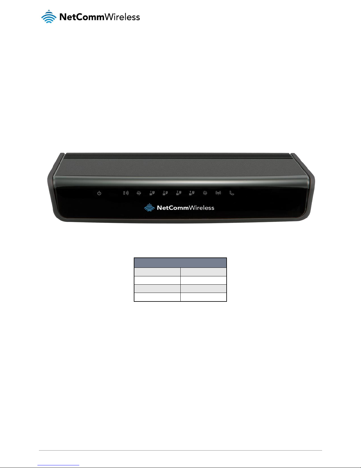
Below is a list of the physical dimensions of the NF13ACV router.
Figure 1 – NF13ACV router dimensions
DIMENSIONS
Length
214 mm
Depth
146 mm
Height
35 mm
Weight
395 grams
Table 2 - Device Dimensions
Page 9
www.netcommwireless.com
NetComm Wireless AC1200 WiFi Gigabit Router with Voice
9
UM-00013 v1.0
LED indicators
The NF13ACV router uses 10 LEDs to display the current system and connection status.
LED ICON
NAME
COLOUR / STATE
DESCRIPTION
Power
Off
Powered off.
Blue
Powered on and operating normally.
Blue Flashing
Starting up.
3G/4G
Off
No 3G/4G configuration present or no 3G/4G dongle plugged in.
Red
SIM Error.
Red Flashing
3G/4G connection failed. Retrying connection.
Blue
Connected to internet via 3G/4G service.
Blue Flashing
Attempting to connect to the 3G/4G service.
WWW (Internet)
Off
No internet configuration present.
Red
Connected via a 3G/4G service.
Red Flashing
Data is being sent or received over the 3G/4G service.
Blue
Connected via an xDSL service.
Blue Flashing
Data is being sent or received via an xDSL service.
Purple
Connected via an Ethernet WAN service.
Purple Flashing
Data is being sent or received over the Ethernet WAN s ervice.
Ethernet 1 - 4
Off
No device is connected to the Ethernet LAN port.
Blue
A device is connected to the Ethernet LAN port.
Blue Flashing
Data is being sent or received via the Ethernet LAN port.
WAN
Off
No device is connected to the Ethernet WAN port.
Blue
A device is connected to the Ethernet WAN port.
WiFi
Off
WiFi is disabled.
Blue
WiFi is enabled.
Blue Flashing
Data is being transferred over WiFi.
Voice
Off
No VoIP service is configured.
Blue
Registered with a configured VoIP service.
Blue Flashing
Attempting to connect to the configured VoIP service.
Table 3 - LED Indicators
Page 10
10
NetComm Wireless AC1200 WiFi Gigabit Router with Voice
www.netcommwireless.com
UM-00013 v1.0
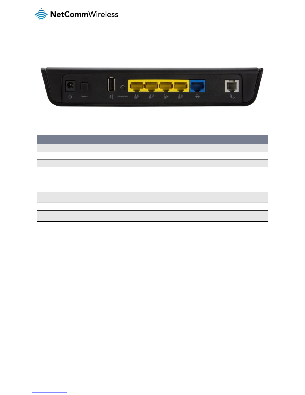
Interfaces
Figure 2 - Interfaces
NO.
ITEM
DESCRIPTION
1
Power jack
Connection point for the included power adapter. Connect the power supply here.
2
Power button
Turns the router on or off.
3
USB 2.0 (3G/4G modem)
Connect a compatible 3G/4G USB modem here.
4
WPS/Reset button
Activate the WiFi WPS PBC function.
a) Hold for 1-3 seconds then release to trigger the 2.4GHz WPS PBC
b) Hold for 4-6 seconds then release to trigger the 5GHz WPS PBC
c) Hold for 15 seconds then release to reset the router to factory default settings.
5
LAN 1–4
Gigabit Ethernet LAN ports. Connect your Ethernet based devices to one of these ports for high -speed
internet access.
6
WAN
Gigabit WAN port for connection to a WAN network.
7
Telephone
Phone port for a standard PSTN analogue telephone handset. Connect a phone to this port to mak e use
of a VoIP service.
Table 4 – Interfaces
Page 11
www.netcommwireless.com
NetComm Wireless AC1200 WiFi Gigabit Router with Voice
11
UM-00013 v1.0
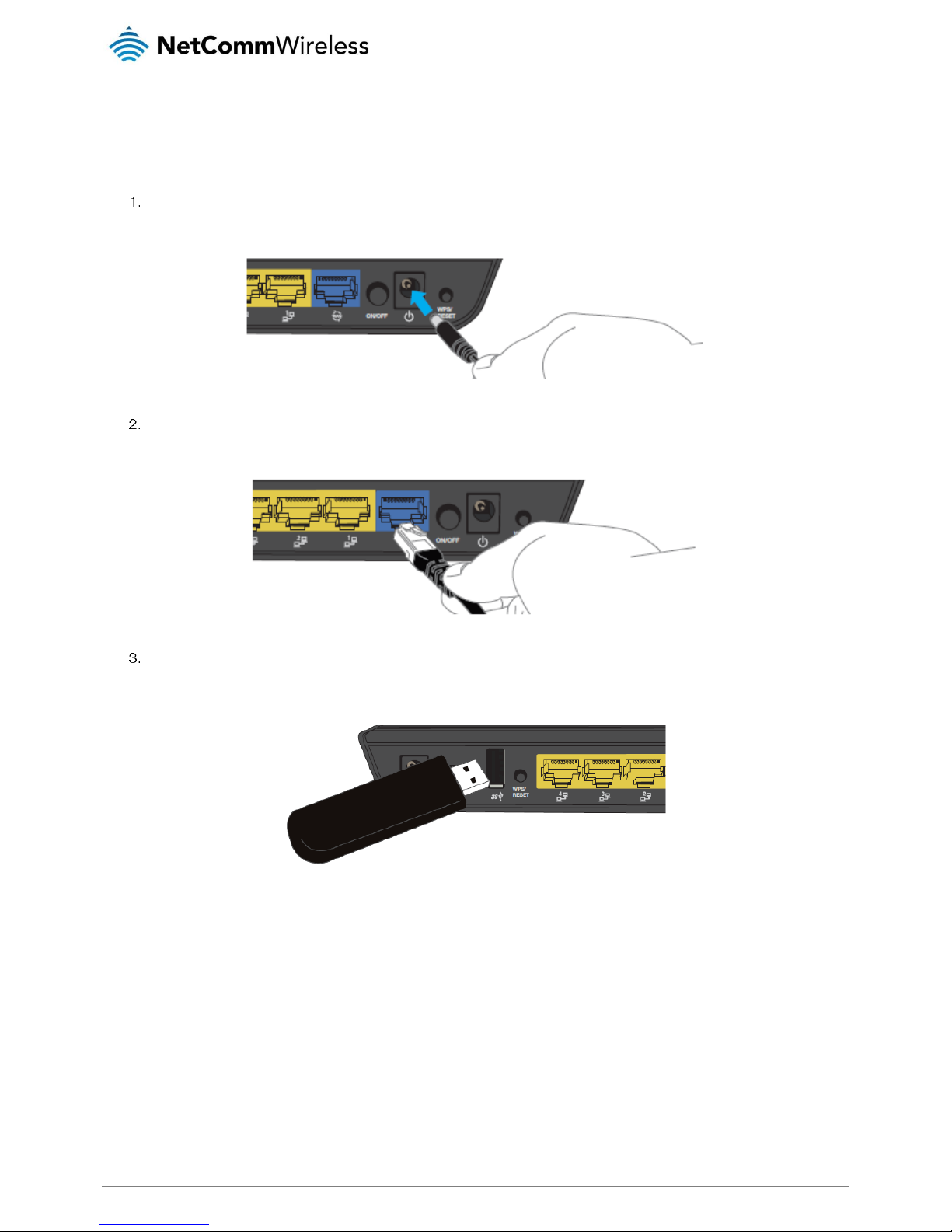
Setting up your router
Connect the included power adapter to the power socket on the rear of the router then connect the other end of it to a
wall power outlet.
Attach one end of the included
Ethernet cable
to the blue
WAN
port on the back of the router. Attach the other end to
your fixed line modem.
If you have a mobile broadband dongle for use as a backup WAN connection, connect it to the USB port on the rear of the
unit.
Page 12
12
NetComm Wireless AC1200 WiFi Gigabit Router with Voice
www.netcommwireless.com
UM-00013 v1.0
Connecting via an Ethernet cable
If you want to connect your computer to the router via Ethernet cable, follow these instructions.
Connect an Ethernet cable to one of the yellow LAN ports on the back of the NF13ACV router.
Connect the other end of the Ethernet cable to your computer.
NOTE: There is only one Ethernet cable supplied. If you require more than one Ethernet cable, any standard Ethernet cable is
suitable.
Connecting via WiFi
Ensure WiFi is enabled on your device (e.g. computer/smartphone/gaming console).
Scan for wireless networks in your area and connect to the network name that matches the Wireless Network Name found
on the Wireless Security Card (included in the box).
When prompted for your wireless security settings, enter the Wireless Security Key listed on your Wireless Security Card.
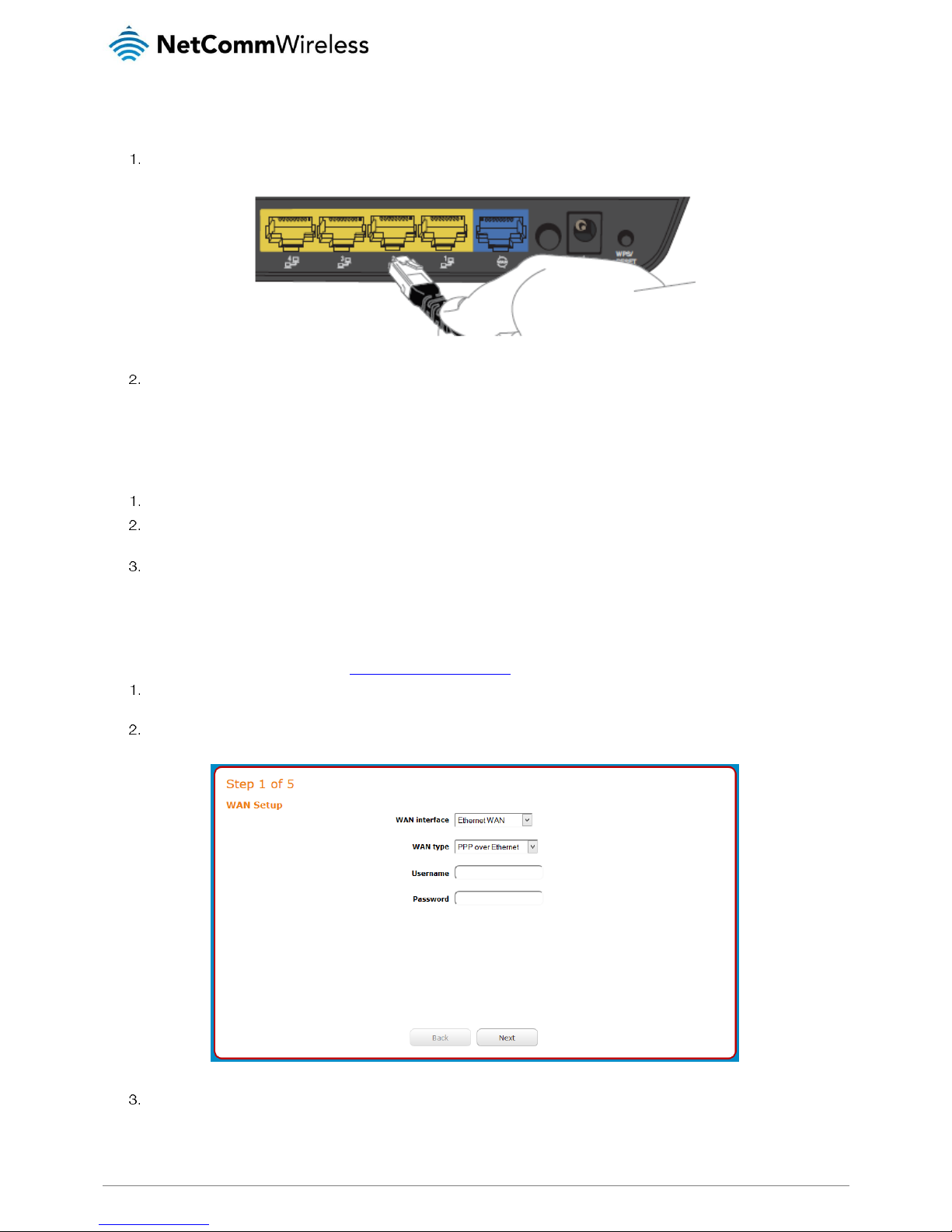
Connecting the router to the Internet
These steps guide you through configuring an Ethernet WAN connection. To configure a Mobile Broadband connection, please
refer to the product User Guide available at www.netcommwireless.com
After you have established a connection to the router using the previous steps, open your web browser and type
http://192.168.20.1 into the address bar at the top of the web browser window and press Enter.
Enter admin into both the Username and Password fields and click Log in. The Startup Wizard is displayed.
Your ISP will have provided you with some details of your connection type. Use the WAN type drop down list to select the
type of connection that you have, then enter the required details for the chosen WAN type. When you have finished, click
the Next button.
Page 13
www.netcommwireless.com
NetComm Wireless AC1200 WiFi Gigabit Router with Voice
13
UM-00013 v1.0
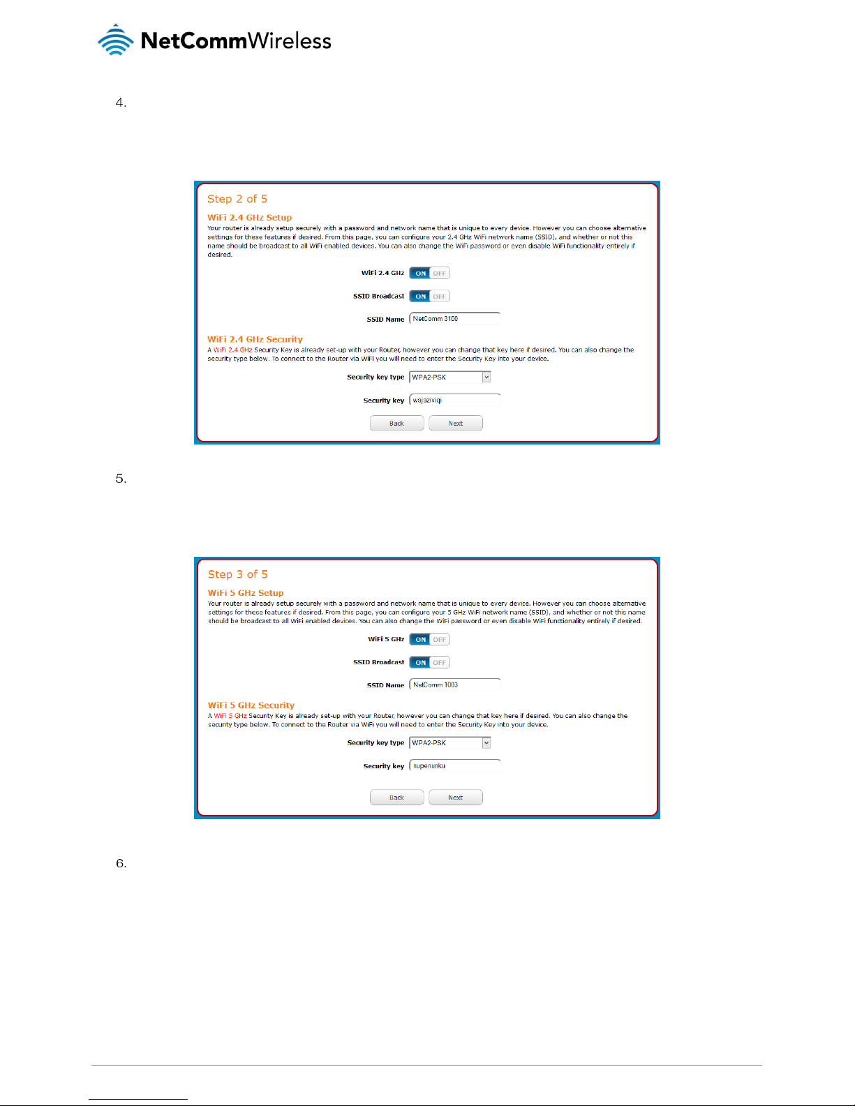
By default, the 2.4GHz WiFi radio is turned on and the SSID (network name) is being broadcast. This means it is
discoverable by wireless client devices when they perform a scan of nearby access points on the 2.4GHz spectrum. Use
this page of the wizard to enable or disable the 2.4GHz WiFi radio and SSID Broadcast status or change the SSID name,
Security key type and the Security key. When you have finished, click the Next button.
By default, the 5GHz WiFi radio is turned on and the SSID (network name) is being broadcast. This means it is
discoverable by wireless client devices when they perform a scan of nearby access points on 5GHz spectrum. Use this
page of the wizard to enable or disable the 5GHz WiFi radio and SSID Broadcast status or change the SSID name,
Security key type and the Security key. When you have finished, click the Next button.
This page allows you to configure the administrator username and password used to access the configuration pages. We
highly recommend that you change the password from the default setting to protect your router from unauthorized access.
When you have finished, click the Next button.
Page 14

14
NetComm Wireless AC1200 WiFi Gigabit Router with Voice
www.netcommwireless.com
UM-00013 v1.0
A summary of your settings is displayed. If any settings are incorrect, click the Back button till you get to the appropriate
step, make the changes then click the Next button until you return to this step. When the settings are correct, click the
Finish button. The router returns to the Status page and the Startup Wizard is complete.
Your router is now ready for use.
Page 15
www.netcommwireless.com
NetComm Wireless AC1200 WiFi Gigabit Router with Voice
15
UM-00013 v1.0
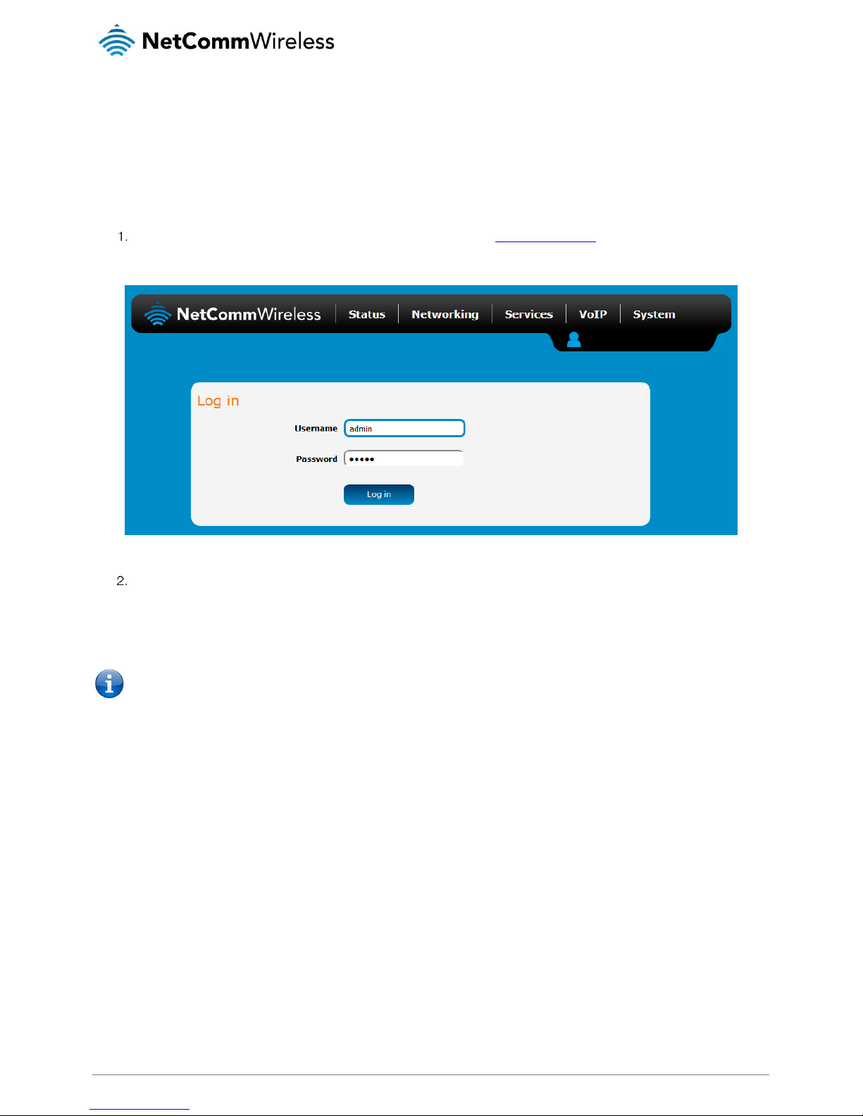
Advanced configuration
The NF13ACV router comes with pre-configured settings that should suit most customers. For advanced configuration, log in to the
web-based user interface of the router.
To log in to the web-based user interface:
Open a web browser (e.g. Google Chrome™, Mozilla Firefox®), type http://192.168.20.1 into the address bar and press
Enter. The web-based user interface log in screen is displayed.
Figure 3 – Log in prompt for the web-based user interface
Enter the login username and password. If this is the first time you are logging in or you have not previously configured the
password for the admin account, you can use the default account details to log in. The default log in credentials are:
Username: admin
Password: admin
Note: For security reasons, we highly recommend that you change the password of the admin account upon initial
installation. You can do so by navigating to the System > Administration > Change password.
The Status page is displayed when you have successfully logged in.
Page 16
16
NetComm Wireless AC1200 WiFi Gigabit Router with Voice
www.netcommwireless.com
UM-00013 v1.0
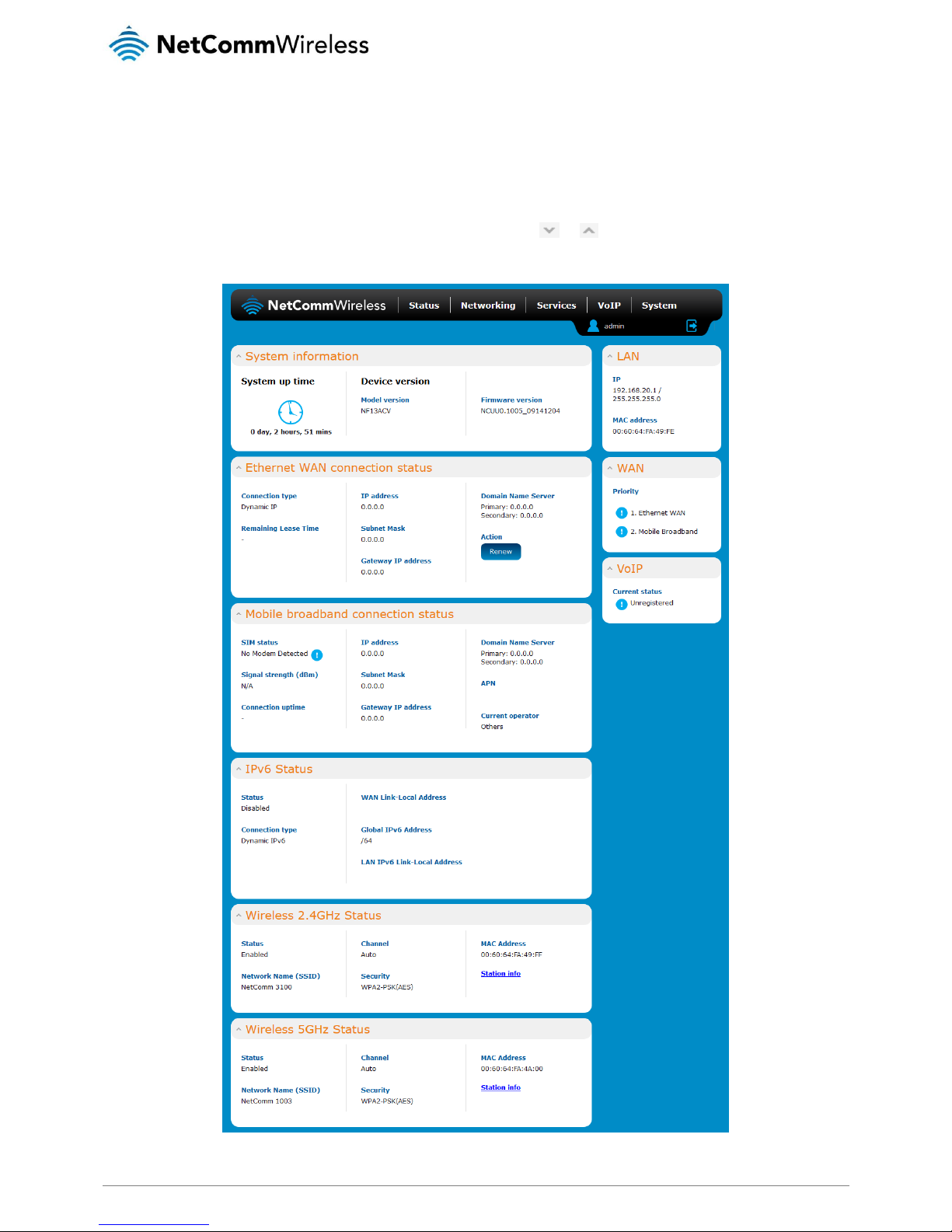
Status
The status page of the web interface provides system related information and is displayed when you log in to the NF13ACV router
management console. The status page shows System information, Ethernet WAN, Mobile broadband, IPv6, Wireless 2.4GHz and
Wireless 5GHz details. You can toggle the sections from view by clicking the or buttons to show or hide them. Extra status
boxes will appear as additional software features are enabled (e.g. VPN connectivity).
Figure 4 - Router status page
Page 17

www.netcommwireless.com
NetComm Wireless AC1200 WiFi Gigabit Router with Voice
17
UM-00013 v1.0
ITEM
DEFINITION
System information
System up time
The current uptime of the router.
Model version
The NetComm Wireless product model.
Firmware version
The firmware version of the router
LAN
IP
The Local IP address and subnet mask of the router.
MAC address
The MAC address of the router.
WAN
Priority
Displays the priority of the available WAN connections.
VoIP
Displays the current registration status of the VoIP service.
Ethernet WAN connection status
Connection type
Displays the Ethernet WAN connection type, i.e. Dynamic IP, Static IP or PPPoE.
Remaining lease time
Displays the remaining lease time for the current connection.
IP address
The WAN IP address of the Ethernet interface.
Subnet mask
The subnet mask of the connection.
Gateway IP address
The gateway IP address of the Ethernet interface.
Domain Name Server
The primary and secondary domain name servers of the connection.
Mobile broadband connection status
SIM status
Displays the activation status of the SIM in the 3G/4G dongle connected to the router.
Signal strength (dBm)
The current signal strength measured in dBm
Connection uptime
The duration of the current mobile broadband connection.
IP address
The IP address of the Mobile Broadband interface.
Subnet mask
The subnet mask of the connection.
Gateway IP address
The gateway IP address of the Mobile Broadband interface.
APN
The Access Point Name currently in use.
Current operator
The current operator network in use.
IPv6 status
Status
The status of the IPv6 connection.
Connection type
The connection type of the IPv6 connection.
WAN Link-Local address
The local-link IPv6 address used for IPv6 sublayer operation.
Global IPv6 address
The routable IPv6 Address used to identify the router on the Internet.
LAN IPv6 Link-Local address
The IPv6 address used for local network communication until an IPv6 prefix is available.
Wireless 2.4GHz status
Status
Shows the current status of the 2.4GHz wireless LAN network.
Network name (SSID)
Shows the network name (SSID) of the 2.4GHz wireless network.
Channel
Shows the channel that the 2.4GHz wireless network is configured to operate on.
Security
The type of wireless security in effect on the wireless radio band.
MAC address
The MAC address of the 2.4GHz wireless radio interface.
Station info
Click the Station Info link to be taken to the station information page providing more information on the connected stations.
Wireless 5GHz status
Status
Shows the current status of the 5GHz wireless LAN network.
Network name (SSID)
Shows the network name (SSID) of the 5GHz wireless network.
Channel
Shows the channel that the 5GHz wireless network is configured to operate on.
Security
The type of wireless security in effect on the wireless radio band.
MAC address
The MAC address of the 5GHz wireless radio interface.
Station info
Click the Station Info link to be taken to the station information page providing more information on the connected stations.
Table 5 - Status page item details
Page 18
18
NetComm Wireless AC1200 WiFi Gigabit Router with Voice
www.netcommwireless.com
UM-00013 v1.0
Networking
The Networking section provides configuration options for WAN, LAN, Wireless 2.4GHz, Wireless 5GHz, Routing and VPN and Port
configuration.
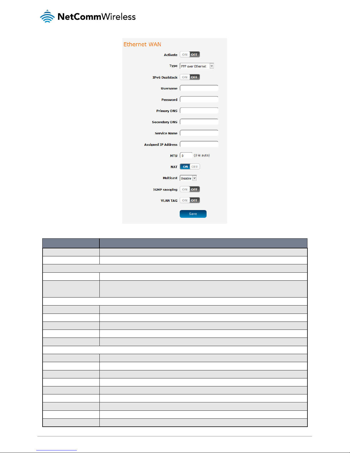
WAN
Ethernet WAN
The Ethernet WAN page allows you to configure settings related to the Ethernet WAN connection. This page is particularly useful
when connecting your router to the internet via the WAN port. To access this page, click on the Networking menu at the top of the
screen.
Figure 5 – Ethernet WAN settings – Dynamic IP address
Figure 6 - Ethernet WAN settings - Static IP address
Page 19
www.netcommwireless.com
NetComm Wireless AC1200 WiFi Gigabit Router with Voice
19
UM-00013 v1.0
Figure 7 - Ethernet WAN settings – PPP over Ethernet
ITEM
DEFINITION
Activate
Turns on or off the Ethernet WAN connection.
Type
Sets the type of Ethernet WAN connection.
Dynamic IP address
Host Name
Set the DHCP option 12 – Hostname, specifies the name of the client that will be sent to the DHCP server.
ISP registered MAC address
Use this field to specify the MAC address that is presented to the ISP. This is useful when the ISP has locked the connection
to a specific MAC address. Pressing the Clone button will automatically enter the MAC address of your computer’s network
card.
Static IP address
WAN IP address
The WAN IP address of your Ethernet WAN connection.
WAN subnet mask
The WAN IP subnet mask of your Ethernet WAN connection.
WAN Gateway
The Gateway address of your Ethernet WAN connection.
Primary DNS
The primary Domain Name Server, usually provided by your WAN service carrier.
Secondary DNS
The secondary Domain Name Server, usually provided by your WAN service carrier.
PPP over Ethernet
IPv6 Dualstack
When set to the ON position, the router also passes the IPv6 protocol over the PPPoE connection simultaneously with IPv4.
Username
The username of the PPPoE connection.
Password
The password of the PPPoE connection.
Primary DNS
The primary Domain Name Server, usually provided by your WAN service carrier.
Secondary DNS
The secondary Domain Name Server, usually provided by your WAN service carrier.
Service Name
The Service Name is used to identify the PPPoE service. This may be required by your ISP in certain circumstances.
Assigned IP address
The IP address assigned to your connection by the carrier.
MTU
The Maximum Transmission Unit. Leave this at 0 to have it automatically set according to the network.
NAT
This toggle switch turns on or off the Network Address Translation function.
Page 20
20
NetComm Wireless AC1200 WiFi Gigabit Router with Voice
www.netcommwireless.com
UM-00013 v1.0
Multicast
Enables or disables multicast. Multicast is used to send IP packets to a group of interested receivers in a single transmission
and is often used for streaming media applications on the internet.
IGMP snooping
Allows the router to listen in on the traffic between hosts and routers to determine which links need IP multicast streams.
VLAN Tag
When turned on, this feature tags packets with the VLAN ID for this interface. The VLAN ID can be set between 1 and 4094.
Table 6 – Ethernet WAN item details
Mobile broadband
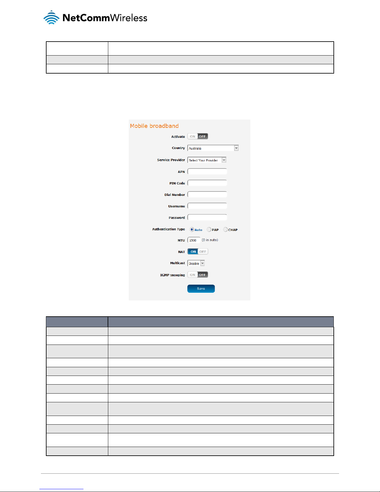
The Mobile broadband page is used to configure settings for an internet connection via a 3G/4G USB dongle. To access this page,
click on the Networking menu at the top of the screen, then under the WAN folder on the left, click the Mobile broadband option.
Figure 8 - Mobile broadband configuration
ITEM
DEFINITION
Activate
Turns on or off the Ethernet WAN connection.
Country
Use the drop down list to select the country in which the service is being used.
Service Provider
Use the drop down list to select the service provider. Selecting the provider automatically populates some fields with the
correct settings.
APN
The Access Point Name used to identify the carrier’s gateway to the internet.
PIN code
The PIN number used to unlock the SIM card, if it is PIN l ocked.
Dial number
The number used to dial the network. Contact your service provider if this is unknown.
Username
The username used to authenticate the mobile broadband account.
Password
The password used to authenticate the mobile broadband account.
Authentication type
In most cases, this can be left as “Auto”, but if you wish to force it to a particular method, you can select PAP (Password
Authentication Protocol) or CHAP (Challenge Handshake Authentication Protocol).
MTU
The Maximum Transmission Unit. Set this to 0 to have it automatically set according to the network.
NAT
This toggle switch turns on or off the Network Address Translation function.
Multicast
Enables or disables multicast. Multicast is used to send IP packets to a group of interested receivers in a single transmission
and is often used for streaming media applications on the internet.
IGMP snooping
Allows the router to listen in on the traffic between hosts and routers to determine which links need IP multicast streams.
Table 7 - Mobile broadband configuration
Page 21
www.netcommwireless.com
NetComm Wireless AC1200 WiFi Gigabit Router with Voice
21
UM-00013 v1.0
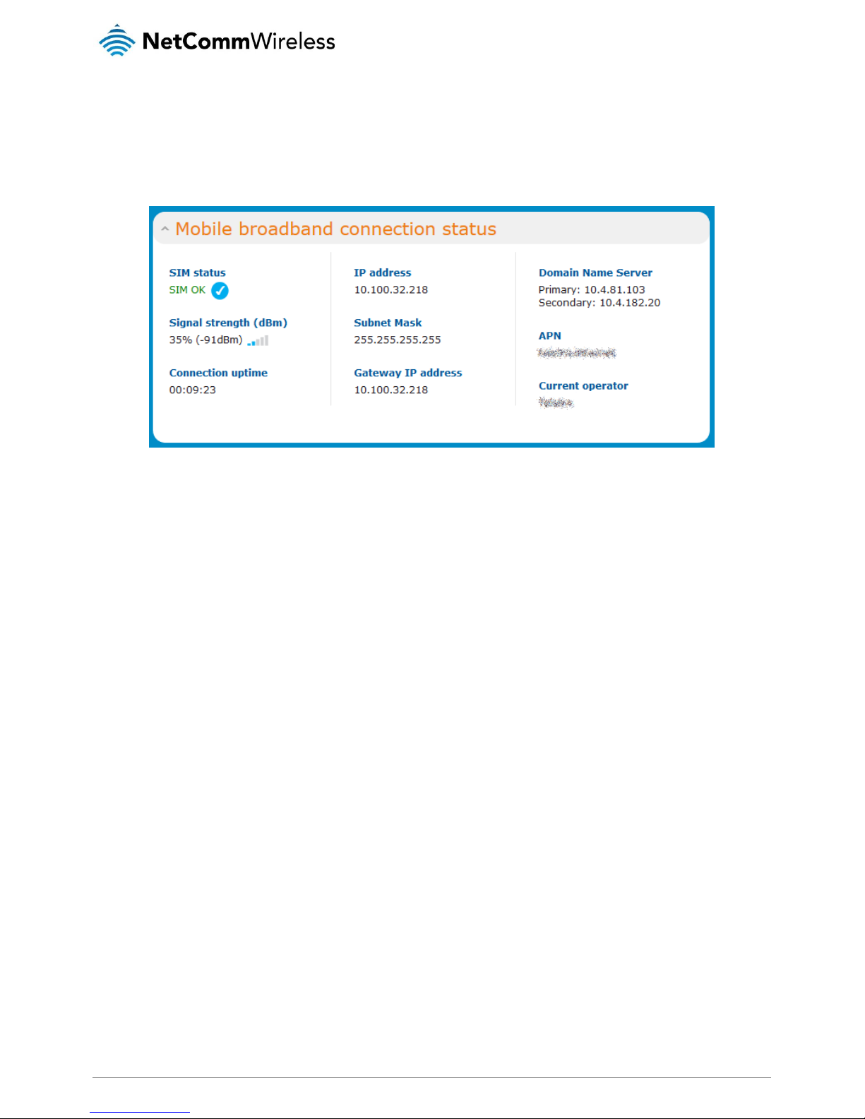
Confirming a successful connection
After configuring the packet data session, and ensuring that it is enabled, click on the Status menu item at the top of the page to
return to the Status page. When there is a mobile broadband connection, the Mobile broadband connection status section shows
the details of the connection and the Connection uptime field shows the duration of the connection. Similarly, if you are using an
Ethernet WAN connection, the Ethernet WAN connection status section displays the IP address, subnet mask and other connection
details indicating that the WAN connection has been established.
Figure 9 – Mobile broadband connection status section
Page 22
22
NetComm Wireless AC1200 WiFi Gigabit Router with Voice
www.netcommwireless.com
UM-00013 v1.0
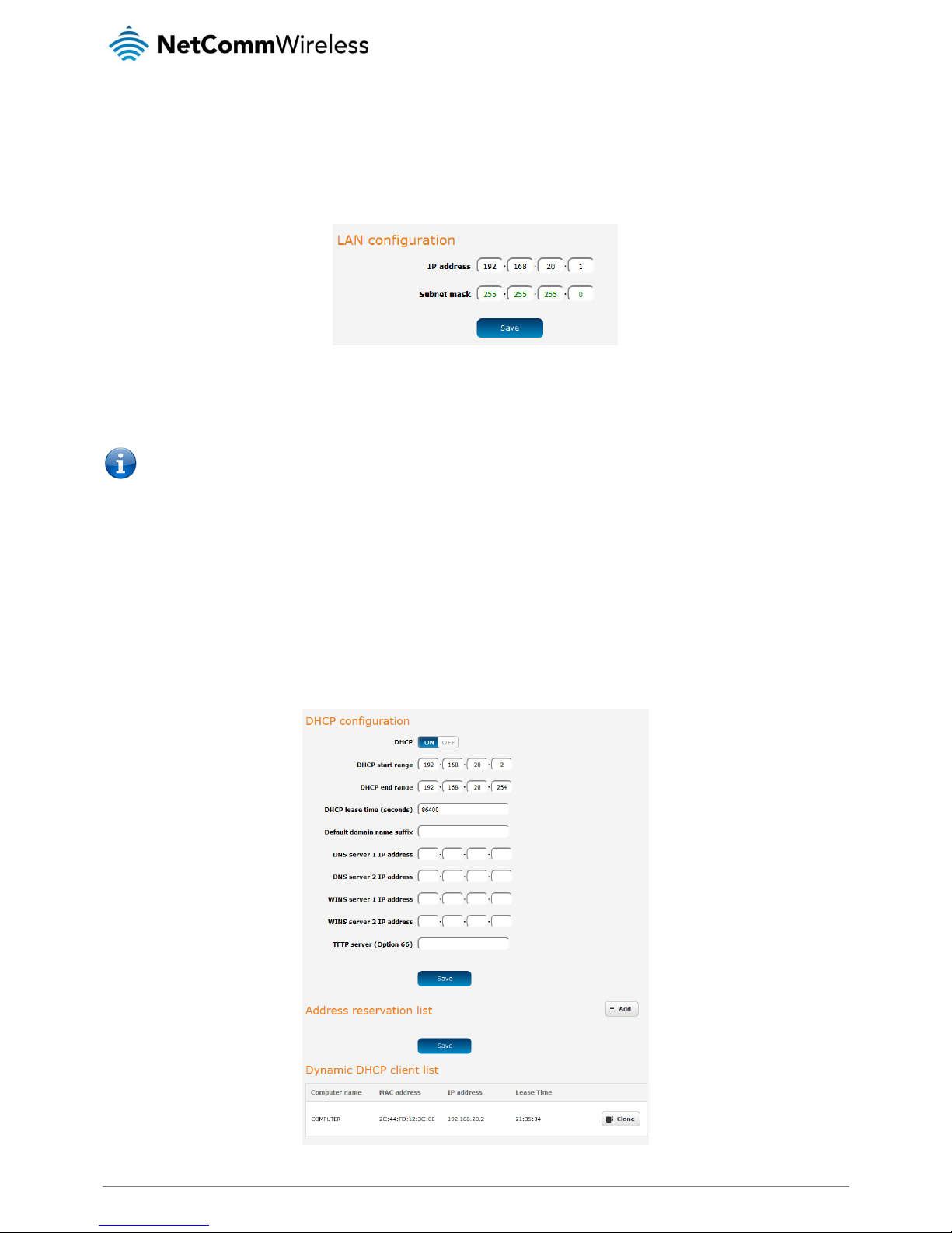
LAN
LAN
The LAN configuration page is used to configure the LAN settings of the router. To access the LAN configuration page, click on the
Networking menu at the top of the screen, then click on the LAN menu on the left.
Figure 10 – LAN configuration settings
The default IP of the LAN port is 192.168.20.1 with subnet mask 255.255.255.0. To change the IP address or Subnet mask, enter
the new IP Address and/or Subnet mask and click the Save button.
Note: If you change the IP address, remember to reboot the router and enter the new IP address into your browser address
bar.
DHCP
The DHCP page is used to adjust the settings used by the router’s built in DHCP Server which assigns IP addresses to locally
connected devices. To access the LAN configuration page, click on the Networking menu at the top of the screen, click on the LAN
menu on the left then select the DHCP menu item.
DHCP configuration
You can manually set the start and end address range to be used to automatically assign addresses within, the lease time of the
assigned address, the default domain name suffix, primary and secondary DNS server, the primary and secondary WINS server, as
well as the advanced DHCP settings such as NTP, TFTP and Option 66.
Figure 11 - DHCP configuration
Page 23

www.netcommwireless.com
NetComm Wireless AC1200 WiFi Gigabit Router with Voice
23
UM-00013 v1.0
OPTION
DESCRIPTION
DHCP start range
Sets the first IP address of the DHCP range
DHCP end range
Sets the last IP address of the DHCP range
DHCP lease time (seconds)
The length of time in seconds that DHCP lease allocated is valid
Default domain name suffix
Specifies the default domain name suffix for the DHCP clients. A domain name suffix enables users
to access a local server, for example, server1, without typing the full domain name
server1.domain.com
DNS server 1 IP address
Specifies the primary DNS (Domain Name System) server’s IP address.
DNS server 2 IP address
Specifies the secondary DNS (Domain Name System) server’s IP address.
WINS server 1 IP address
Specifies the primary WINS (Windows Internet Name Service) server IP address
WINS server 2 IP address
Specifies the secondary WINS (Windows Internet Name Service) server IP address
TFTP Server (Option 66)
Specifies the TFTP (Trivial File Transfer Protocol) server
Table 8 - DHCP configuration
Enter the desired DHCP options and click the Save button.
Address reservation list
DHCP clients are dynamically assigned an IP address as they connect, but you can reserve an address for a particular device using
the address reservation list.
Figure 12 – DHCP – Address reservation list
To add a device to the address reservation list:
Click the +Add button.
In the MAC address field, enter the device’s MAC address.
In the IP address fields, enter the IP address that you wish to reserve for the device.
If the Enable toggle key is not set to ON, click it to switch it to the ON position.
Click the Save button to save the settings.
Dynamic DHCP client list
The Dynamic DHCP client list displays a list of the DHCP clients. If you want to reserve the current IP address for future use, click
the Clone button and the details will be copied to the address reservation list fields. Remember to click the Save button under the
Address reservation list section to confirm the configuration.
Figure 13 - Dynamic DHCP client list
Page 24

24
NetComm Wireless AC1200 WiFi Gigabit Router with Voice
www.netcommwireless.com
UM-00013 v1.0
Wireless 2.4GHz / Wireless 5GHz
The Wireless 2.4GHz and Wireless 5GHz pages allow you to configure the mode and security settings related to the WiFi function of
the router.
Access point
The Access point page provides options such as for turning the WiFi access point on or off, modes of operation, and frequency
settings. To access this page, click on the Networking menu, then click on the Wireless 2.4GHz or Wireless 5GHz folder and finally,
click on the Access point menu item.
Figure 14 - Wireless setup
OPTION
DEFINITION
Wireless module
The WiFi access point is turned on by default. Changing this option to OFF will turn OFF the wireless access point functionality of the
NF13ACV and you will not be able to connect to it with a wireless client.
SSID
The name of the wireless network.
SSID Broadcast
Displays whether the network is broadcasting the SSID. If it is broadcasting, the network will be discoverable by clients. If SSID
Broadcast is off, clients must know the SSID in order to join the network.
Frequency (Channel)
Select the wireless channel of the access point that the wireless signal will broadcast on.
Channel Bandwidth
A higher channel width typically results in higher throughput, however, interference can lead to reduced performance. The 20 MHz
channel width also allows legacy devices to be used.
Network mode
There are 6 possible network modes to use depending on the capability of your devices’ wireless network cards. Each mode represents
one or more wireless network protocols. Each wireless device will be capable of receiving some but possibly not all of wireless broadcast
protocol types. They are:
802.11b/g mixed mode.
802.11b only.
802.11g only.
802.11n only.
802.11b/g/n mixed mode.
802.11a only
802.11an mixed mode
802.11a/n/ac mixed mode
Authentication
The type of wireless network security in use.
Encryption
The type of encryption in use on the network. This may be AES or TKIP
Pre-shared key
This is the password that must be entered on a client device in order to join the access point’s wireless network.
Schedule
Use the drop down menu to select a schedule. This allows you to schedule the WiFi radio to use according to a specific time schedule.
Table 9 - Wireless setup
Page 25

www.netcommwireless.com
NetComm Wireless AC1200 WiFi Gigabit Router with Voice
25
UM-00013 v1.0
WPS
Wi-Fi Protected Setup (WPS) is a simple method used to connect wireless client devices to wireless access points. It works by one
of two methods; Push Button Connect (PBC) or PIN code. The Push Button Connect method involves pressing a button on the two
devices within the space of two minutes while the PIN code method requires that the same PIN number is entered on both the
client and access point to authenticate.
Figure 15 – WPS
OPTION
DEFINITION
WPS function
Enables the WPS function.
Access point PIN
Displays the current PIN that must be entered on the client in order to connect to this access point.
Generate new PIN
Click this button to force the router to generate a new PIN code.
Configuration mode
There are two configuration modes that you may select. As a registrar, the router awaits a request from an enrollee to join the network.
As an enrollee, the router sends out the configured PIN to a registrar. It does not matter if the router acts as a registrar or enrollee for the
setup process.
Configuration status
Displays that the settings above are configured and ready to be used.
Release / Set
When you have selected a PIN and configuration mode, click the Set button to set WPS to use those settings. To change the details,
click the Release button.
Configuration method
Selects between Push Button Connect and PIN code methods.
Table 10 - WPS
Using the Push Button Connect method
To connect a device to your router using the PBC method:
Press the WPS button on the back of the router.
Within two minutes of pressing the WPS button on the router, press the WPS button on your client device. The connection
is established.
An alternative method of triggering the PBC method is to do it from the web user interface. From the WPS page above, use the
Configuration method drop down menu to select Push Button Connect, then click the Trigger button. Within two minutes of
pressing the trigger button, press the WPS button on your client device. The connection is established.
Using the PIN code method
From the Configuration method drop down list, select PIN code.
From the Configuration mode drop down list, select Registrar or Enrollee.
If the router is configured as Registrar, enter the desired PIN code. The PIN must be exactly eight (8) numerals in length. If
the router is configured as Enrollee, enter the PIN code in the Access point PIN field on the client device.
Click the Trigger button and within two minutes, trigger the WPS function on your client device. The WPS connection is
established.
Page 26

26
NetComm Wireless AC1200 WiFi Gigabit Router with Voice
www.netcommwireless.com
UM-00013 v1.0
Wireless Distribution System (WDS)
A wireless distribution system (WDS) is a system enabling the wireless interconnection of access points in an IEEE 802.11 network.
WDS makes it possible to configure a network where a single router acts as a gateway while other routers in the network provide
additional geographical coverage for wireless clients, acting as bridges and redirecting traffic through the same gateway. WDS
provides layer 2 bridging and preserves the MAC addresses of stations connected through the WDS network. The advantage of
WDS is that you can have one network covering a larger geographical area and allow those clients to easily roam between the
access points while retaining their IP addresses. It also means that they are not isolated from each other and allows for easier
configuration since you do not need to configure many port forwarding rules on each access point.
Although it may be possible, NetComm Wireless provides no guarantee that the WDS feature of this router will work with third party
routers.
To access the WDS page, click on Networking, select Wireless 2.4GHz or Wireless 5GHz (depending on the frequency you wish to
use), then select the WDS item.
Configuring WDS
To configure a WDS network:
Click the WDS toggle key so that it is in the ON position.
Enter the MAC address of the other APs in the AP MAC Address fields provided.
On the other routers, enter the MAC address of the original router and any other routers that will join the WDS network.
Click the Save button on all the routers.
Station info
The Station info page shows the number of devices currently connected to your NF13ACV via the 2.4GHz/5GHz wireless radios.
The MAC address, SSID, and IP address of these devices are displayed.
To access the AP station info page, click on the Networking menu at the top of the screen, click on the Wireless 2.4GHz or Wireless
5GHz menu on the left then select the AP station info menu item.
Figure 16 - Wireless Station List
Page 27

www.netcommwireless.com
NetComm Wireless AC1200 WiFi Gigabit Router with Voice
27
UM-00013 v1.0
Routing
The routing pages provide options for firewall, port forwarding, port triggering, DMZ, packet filtering, MAC filtering, domain filtering,
static routing, RIP and URL blocking.
Router firewall
This page provides options for the built-in firewall of the router. To access the Router firewall page, click on Networking, Routing
and then Router firewall.
Figure 17 - Router firewall
OPTION
DEFINITION
Enable router
firewall
Enables or disables the stateful firewall of the router.
Enable NAT
loopback
Enables or disables the NAT loopback feature. NAT loopback allows a local machine to access a service via the public IP address from inside the
network. For example, a web server operated on a machine inside the network can be access locally by another machine via the use of NAT
loopback using the public address.
Table 11 - Router firewall
Port forwarding
The Port forwarding list is used to configure the Network Address Translation (NAT) rules currently in effect on the router. To access
the Port forwarding page, click on the Networking menu at the top of the screen, click on the Routing menu on the left, then click
on the Port forwarding menu item.
Figure 18 – Port forwarding list
The purpose of the port forwarding feature is to allow mapping of inbound requests to a specific port on the WAN IP address to a
device connected on the Ethernet interface.
Adding a port forwarding rule
To create a new port forwarding rule:
Click the +Add button. The port forwarding settings screen is displayed.
Use the Protocol drop down list to select the type of protocol you want to use for the rule. The protocols selections
available are TCP, UDP and All.
The Source port range (From) and (To) fields are used to specify the port(s) on the source side that are to be forwarded.
This allows you to send a range of consecutive port numbers by entering the first in the range in the (From) field and the
last in the range in the (To) field. To forward a single port, enter the port in the (From) field and repeat it in the (To) field.
In the Destination network address field, enter the IP address of the client to which the traffic should be forwarded.
Page 28

28
NetComm Wireless AC1200 WiFi Gigabit Router with Voice
www.netcommwireless.com
UM-00013 v1.0
The Destination port range (From) and (To) fields are used to specify the port(s) on the destination side that are to be
forwarded. If the Source port range specifies a single port then the destination port may be configured to any port. If the
Source port range specifies a range of port numbers then the Destination port range must be the same as the Source port
range.
Click the Save button to confirm your settings.
Figure 19 - Port forwarding settings
To delete a port forwarding rule, click the button on the Port forwarding list for the corresponding rule that you would like to
delete.
Port triggering
Some applications such as online games, video conferencing and Internet telephony require multiple connections to the internet. As
such, it is sometimes better to configure port triggering so that when an outbound request on the trigger port is made, the incoming
ports are opened.
The Port triggering feature allows some of these applications to work with this router.
Note: If port triggering doesn’t work, rule out application issues first by configuring the computer as the DMZ host instead.
Page 29

www.netcommwireless.com
NetComm Wireless AC1200 WiFi Gigabit Router with Voice
29
UM-00013 v1.0
OPTION
DEFINITION
Trigger
The outbound port number that will be triggered by the application.
Incoming Ports
When the trigger packet is detected, the inbound packets sent to the specified port numbers will be allowed to pass through the
firewall.
Activate
Select to enable or disable the configured entry.
Click the Save button to save your settings.
DMZ
A Demilitarized Zone (DMZ) Host is a computer without the protection of firewall. It allows that particular computer unrestricted 2way communication to the internet. It is mostly used for Hosting servers, Internet games, Video conferencing, Internet telephony
and other special applications.
To access the DMZ page, click on the Networking menu at the top of the screen, click on the Routing menu on the left, then click
on the DMZ menu item.
Figure 20 - DMZ
To set a local machine as the DMZ host:
Click the DMZ toggle key so that it is in the ON position.
Enter the local IP address of the device to become the DMZ host.
Packet filtering
The Packet Filter enables you to control what packets are allowed to pass through the router. There are two types of packet filter,
Outbound Packet Filter which applies to all outbound packets and the Inbound Packet Filter which only applies to packets that are
destined for a Virtual Server or DMZ host. To access the Packet filtering page, click on the Networking menu at the top of the
screen, click on the Routing menu on the left, then click on the Packet filtering menu item.
Figure 21 - Packet filtering
Page 30

30
NetComm Wireless AC1200 WiFi Gigabit Router with Voice
www.netcommwireless.com
UM-00013 v1.0
There are two types of filtering actions:
Accept the following packets.
Drop the following packets.
These actions can be specified separately for inbound and outbound packets.
You can specify filtering rules for each direction (Inbound or Outbound). For each rule you must enter the following details:
Source IP address
Destination IP address
Destination port
Schedule
The Packet Filter also works with scheduling rules so that you can have the packet filtering rules apply only at times that suit you.
Note: For further instructions on scheduling rules, please refer to the “Scheduling” section later in this guide
Click Save to save the settings or Undo to cancel.
MAC filtering
MAC filtering allows you to allow or deny network access to devices specified by their MAC address. To access the MAC filtering
page, click on the Networking menu at the top of the screen, click on the Routing menu on the left, then click on the MAC filtering
menu item.
Figure 22 - MAC filtering
Page 31

www.netcommwireless.com
NetComm Wireless AC1200 WiFi Gigabit Router with Voice
31
UM-00013 v1.0
To use MAC filtering:
Select the Whitelist or Blacklist option. If Whitelist is selected, only the listed devices will be granted access to the network.
If Blacklist is selected, all devices are granted network access except the devices listed below.
Add the MAC addresses one at a time in the MAC Address List fields. The MAC addresses must be entered with a colon
character separating the hexadecimal character pairs, e.g. 01:23:45:67:89:AB.
Click the Activate toggle key so that it is in the ON position for the devices to which you would like MAC filtering to apply.
To enable the MAC address filtering function, click the global Activate toggle key at the top of the page so that it is in the
ON position.
Click the Save button to save the configuration.
Domain filtering
The Domain filtering feature is provided to allow the administrator to block access to particular domain names from all devices
(except those in the privileged range).
To access the Domain filtering page, click on the Networking menu at the top of the screen, click on the Routing menu on the left,
then click on the Domain filtering menu item.
Figure 23 - Domain filtering
To configure a list of domains to be filtered:
Enter the domain suffixes in the Domain Suffix fields, for example, domainname.com.au.
In the Action column, check the items that you want to apply when the domain is accessed. The “Drop” action denies
access to the domain while the “Log” action logs the request to the System log file.
Click the Activate toggle key next to the rule so that it is in the ON position.
To enable the Domain filter globally, click the Activate toggle key at the top of the page so that it is in the ON position.
If you want to log DNS queries to the listed domains, click the Log DNS query toggle key so that it is in the ON position.
Click the Save button.
Page 32

32
NetComm Wireless AC1200 WiFi Gigabit Router with Voice
www.netcommwireless.com
UM-00013 v1.0
Static routing
Static routing is the alternative to dynamic routing used in more complex network scenarios and is used to facilitate communication
between devices on different networks. Static routing involves configuring the routers in your network with all the information
necessary to allow the packets to be forwarded to the correct destination. If you change the IP address of one of the devices in the
static route, the route will be broken.
To access the Static routing page, click on the Networking menu at the top of the screen, click on the Routing menu on the left,
then click on the Static Routing menu item.
Figure 24 - Static routing
Some routes are added by default by the router on initialization such as the Ethernet subnet route for routing to a device on the
Ethernet subnet.
Adding Static Routes
To add a new route to the static routing list, click the +Add button. The Static routes page appears.
In the Destination network address field, enter the IP address of the destination of the route.
In the Destination subnet mask field, enter the subnet mask of the route.
In the Gateway IP address field, enter the IP address of the gateway that will facilitate the route.
In the Metric field enter the metric for the route. The metric value is used by the router to prioritise routes. The lower the
value, the higher the priority. To give the route the highest priority, set it to 0.
Click the Static Routing toggle key at the top of the page to turn on the Static routing feature globally.
Click the Save button to save your settings.
Page 33

www.netcommwireless.com
NetComm Wireless AC1200 WiFi Gigabit Router with Voice
33
UM-00013 v1.0
Figure 25 - Adding a static route
Active routing list
Static routes are displayed in the Active routing list.
Figure 26 - Active routing list
Deleting static routes
From the static routing list, click the icon to the right of the entry you wish to delete.
Figure 27 - Deleting a static route
Page 34

34
NetComm Wireless AC1200 WiFi Gigabit Router with Voice
www.netcommwireless.com
UM-00013 v1.0
RIP
RIP (Routing Information Protocol) is used for advertising routes to other routers. Thus all the routes in the router’s routing table will
be advertised to other nearby routers. For example, the route for the router’s Ethernet subnet could be advertised to a router on the
PPP interface side so that a router on this network will know how to route to a device on the router’s Ethernet subnet. Static routes
must be added manually according to your requirements. See Adding Static Routes.
To access the RIP configuration page, click on the Networking menu at the top of the screen, click on the Routing failover menu on
the left, then click on the RIP menu item.
Note: Some routers will ignore RIP.
Figure 28 - RIP configuration
To enable Routing Information Protocol (RIP)
Click the RIP toggle key to switch it to the ON position.
Using the Version drop down list, select the version of RIP that you would like to use.
Click the Save button to confirm your settings.
Page 35

www.netcommwireless.com
NetComm Wireless AC1200 WiFi Gigabit Router with Voice
35
UM-00013 v1.0
URL blocking
URL blocking allows you to specify a keyword or string of characters and any website that contains this string of characters in the
URL will be blocked.
To access the URL blocking configuration page, click on the Networking menu at the top of the screen, click on the Routing failover
menu on the left, then click on the URL blocking menu item.
Figure 29 - URL blocking
To use the URL blocking feature:
1. In one of the URL fields, enter a keyword or string of text to block.
2. Click the Activate toggle key next to it so that it is in the ON position.
3. Click the URL blocking toggle key at the top of the page so that it is in the ON position.
4. Click the Save button.
Page 36

36
NetComm Wireless AC1200 WiFi Gigabit Router with Voice
www.netcommwireless.com
UM-00013 v1.0
VPN
IPSec
IPSec operates on Layer 3 of the OSI model and as such can protect higher layered protocols. IPSec is used for both site to site
VPN and Remote Access VPN. The NF13ACV router supports IPsec end points and can be configured with Site to Site VPN
tunnels with third party VPN routers.
Figure 30 - IPSec settings
OPTION
DEFINITION
VPN-IPSec
Enables/disables the IPSec VPN service.
NetBIOS over IPSec
When enabled, this passes the NetBIOS protocol over the IPSec VPN.
NAT Traversal
When enabled, this allows the IPSec protocol to traverse the network address translation of the router.
Max. number of tunnels
Sets the maximum number of tunnels that may be used over the IPSec connection.
Table 12 - IPSec
Page 37

www.netcommwireless.com
NetComm Wireless AC1200 WiFi Gigabit Router with Voice
37
UM-00013 v1.0
IPSec Tunnel options
Figure 31 - IPSec tunnel options
Page 38

38
NetComm Wireless AC1200 WiFi Gigabit Router with Voice
www.netcommwireless.com
UM-00013 v1.0
OPTION
DEFINITION
Tunnel name
A name used to identify the VPN connection profile.
Method
Selects whether to use Internet Key Exchange (IKE) or Manual mode.
Local subnet
Enter the IP address of the local network for use on the VPN connection.
Local netmask
Enter the subnet mask in use on the local network.
Remote subnet
Enter the IP address of the remote network for use on the VPN connection.
Remote netmask
Enter the subnet mask in use on the remote network.
Remote gateway
Enter the gateway to use on the remote network.
Phase1 Key Life Time
Enter the time in seconds for the phase1 key lifetime.
Phase2 Key Life Time
Enter the time in seconds for the phase2 key lifetime.
Encapsulation protocol
Select the encapsulation protocol to use with the VPN connection. You can choose ESP, AH or ESP+AH
PFS group
Choose the type of Perfect Forward Secrecy for the VPN connection.
Aggressive mode
Puts IKE SA negotiation into three packets, with all data required for the SA pass by the initator.
Pre-shared key
The pre-shared key is the key that peers used to authenticate each other for Internet Key Exchange. Double quotation marks (“)
are not supported in this field.
Connecting type
Determines how the IPSec connection is made. Options are On demand, Always on and Manual.
Remote ID
Specifies the domain name of the remote network.
Local ID-ID
Specifies the domain name of the local network.
Dead Peer Detection (DPD)
Turns on or off the dead peer detection keep alive messages.
XAUTH
Provides authentication options for the XAUTH method.
Set IKE Proposal
Turns on or off the Internet Key Exchange proposal method and provides configuration options for the IKE.
Set IPSec Proposal
Turns on or off the IPSec proposal method and provides configuration options for the IKE.
Figure 32 - IPSec tunnel configuration
L2TP client
The Layer 2 Tunneling Protocol is a tunneling protocol used to support virtual private networks (VPNs). The NF13ACV supports
MPPE (Microsoft Point-to-Point Encryption) and CCP PPP Compression Control Protocol.
Figure 33 - L2TP client
Page 39

www.netcommwireless.com
NetComm Wireless AC1200 WiFi Gigabit Router with Voice
39
UM-00013 v1.0
When you have selected the L2TP client options, click the Edit button to enter authentication details.
Figure 34 - L2TP client authentication details
L2TP server
Here you can configure the L2TP server settings.
Figure 35 - L2TP server
Page 40

40
NetComm Wireless AC1200 WiFi Gigabit Router with Voice
www.netcommwireless.com
UM-00013 v1.0
OPTION
DEFINITION
VPN-L2TP server
Enables/disables the L2TP server.
Server virtual IP
Specifies the L2TP server network IP address.
IP pool start address
Specifies the start of the IP pool address range to assign to clients.
IP pool end address
Specifies the end of the IP pool address range to assign to clients.
Authentication protocol
Select the Authentication protocols to use. Options are PAP, CHAP, MS_CHAP and MS_CHAPv2.
MPPE encryption mode
Enables/disables the Microsoft Point-to-Point Encryption protocol.
NAT
Enables/disables network address translation on the L2TP server network.
Encryption length
Selects the level of encryption applied to the tunnel.
Table 13 - L2TP server
PPTP client
The Point-to-Point Tunnelling Protocol (PPTP) is a method for implementing virtual private networks using a TCP and GRE tunnel to
encapsulate PPP packets. PPTP operates on Layer 2 of the OSI model and is included on Windows computers.
Figure 36 - PPTP client
When you have selected the PPTP client options, click the Edit button to enter authentication details.
Page 41

www.netcommwireless.com
NetComm Wireless AC1200 WiFi Gigabit Router with Voice
41
UM-00013 v1.0
Figure 37 - PPTP client authentication details
PPTP server
Here you can configure the PPTP server settings.
Figure 38 - PPTP server
Page 42

42
NetComm Wireless AC1200 WiFi Gigabit Router with Voice
www.netcommwireless.com
UM-00013 v1.0
OPTION
DEFINITION
VPN-PPTP server
Enables/disables the PPTP server.
Server virtual IP
Specifies the PPTP server network IP address.
IP pool start address
Specifies the start of the IP pool address range to assign to clients.
IP pool end address
Specifies the end of the IP pool address range to assign to clients.
Authentication protocol
Select the Authentication protocols to use. Options are PAP, CHAP, MS_CHAP and MS_CHAPv2.
MPPE encryption mode
Enables/disables the Microsoft Point-to-Point Encryption protocol.
NAT
Enables/disables network address translation on the PPTP server network.
Encryption length
Selects the level of encryption applied to the tunnel.
Table 14 - PPTP server
Port configuration
The port configuration page provides the ability to manually configure the speed of each of the LAN and WAN ports to 100Mbps full
or half duplex or 10Mbps full or half duplex. When Auto is selected, the NF13ACV selects the highest possible speed that both
nodes are capable of. Selecting Auto therefore prioritizes Gigabit Duplex connectivity.
To access the Port configuration page, click on the Networking menu at the top of the screen then click on the Port configuration
menu item.
Use the drop down lists to select the mode you want the chosen port to operate at. In most cases, it is best to leave these settings
as “Auto” but there may be situations where you want to limit or force a port to behave in a certain manner.
When you have finished making changes, click the Save button to ensure that your changes take effect.
Page 43

www.netcommwireless.com
NetComm Wireless AC1200 WiFi Gigabit Router with Voice
43
UM-00013 v1.0
Services
The Services pages provide options for configuring Universal Plug n Play, Dynamic DNS, Quality of Service, SNMP, Network Time
Protocol, Scheduling, IPv6 and TR-069.
UPnP settings
Universal Plug n Play protocols allow devices such as computers, printers, WiFi access points and mobile devices on the same
network to automatically discover each other.
To access the Universal Plug and Play page, click on the Services menu at the top of the screen then click on the UPnP settings
menu item.
Figure 39 - UPnP settings
Click the Option toggle key to turn UPnP on or off then click the Save button to save the configuration.
Page 44

44
NetComm Wireless AC1200 WiFi Gigabit Router with Voice
www.netcommwireless.com
UM-00013 v1.0
DDNS
Dynamic DNS allows the router to update a name server with its current IP address. This is useful for connections where the IP
address changes between sessions. A number of Dynamic DNS hosts are available from which to select. To access the Dynamic
DNS page, click on the Services menu at the top of the screen then click on the Dynamic DNS menu item on the left.
Figure 40 – Dynamic DNS settings
Dynamic DNS provides a method for the router to update an external name server with the current WAN IP address.
To configure dynamic DNS:
Click the DDNS configuration toggle key to switch it to the ON position.
From the Dynamic DNS drop down list, select the Dynamic DNS service that you wish to use. The available DDNS services
available are:
DynDNS.org (Dynamic)
DynDNS.org (Custom)
No-IP.com
TZO.com
dhs.org
Enter your hostname in ‘Host name’ field.
In the Username and Password fields, enter the logon credentials for your DDNS account. Enter the password for the
account again in the Verify password field.
Click the Save button to save the DDNS configuration settings.
Page 45

www.netcommwireless.com
NetComm Wireless AC1200 WiFi Gigabit Router with Voice
45
UM-00013 v1.0
QoS
Quality of Service (QoS) is a collection of network technologies which allow configuration of different priorities for different
applications, users or data flows in order to guarantee a certain level of performance. The ultimate goal of QoS is to guarantee that
the network delivers predictable results for availability, throughput, latency and error rate. QoS is especially important in ensuring the
smooth operation of real-time streaming applications such as Voice over IP (VoIP), IPTV and online games.
As part of a strategy to provide Quality of Service, the NF13ACV supports Type of Service (ToS), the Differentiated Services
(DiffServ) architecture and IEEE P802.1p priority tags (specified in the IEEE 802.1Q standard). DiffServ is a mechanism for classifying
and managing network traffic by marking each packet on the network with a Differentiated Services Code Point (DSCP) which is a
field in an IP packet used for classification purposes and operates at the IP layer. The NF13ACV also supports 802.1p priority tags
which operate at the media access control (MAC) level. ToS, like DSCP, is a field in the header of IP packets that marks packets
with different types of service such as minimize delay, maximize throughput, maximize reliability, minimize cost or normal service.
Figure 41 - Quality of Service
OPTION
DEFINITION
Option
Click the toggle key to Enable or Disable QoS.
WAN interface
Displays the interface that the QoS feature applies to.
QoS mode
Use the drop down list to select the type of QoS to apply. Smart-QoS lets the router decide on the best settings based
on the types of service you select below and the percentage setting assigned to each type of service. Higher
percentages give a higher quality of service for that service type.
Downstream bandwidth
Enter the downstream bandwidth in Kilobits per second of your connection so that the router can calculate the best QoS
settings.
Upstream bandwidth
Enter the upstream bandwidth in Kilobits per second of your connection so that the router can calculate the best QoS
settings.
Flexible bandwidth management
In Smart-QoS mode, when Flexible Bandwidth Management is enabled, you are able to select certain types of traffic to
prioritise. The bandwidth allocated to each type of traffic is automatically divided by the number of types selected, for
example, if you select “Game”, “VoIP” and “Video”, the router reserves 10% of bandwidth for other types of traffic and
splits the remaining 90% of bandwidth equally among the 3 selected types, allowing each type 30% of bandwidth when
each type of traffic is concurrently in use. If, for example, only two types of that traffic are in use, the 30% bandwidth
allocated to the type of traffic not in use is re -distributed to other applications.
When Flexible Bandwidth Management is disabled, you are able to manually specify the percentage of bandwidth to
allocate to each type of traffic, however, you must still allow for 10% of bandwidth to be reserved for other types of
traffic.
Table 15 - Quality of Service
Page 46

46
NetComm Wireless AC1200 WiFi Gigabit Router with Voice
www.netcommwireless.com
UM-00013 v1.0
SNMP
SNMP (Simple Network Management Protocol) is a protocol designed to give a user the capability to remotely manage a computer
network by polling and setting terminal values and monitoring network events.
Figure 42 - SNMP
OPTION
DEFINITION
Enable SNMP
You must check Local, Remote or both to enable SNMP function. If Local is checked, this device will only respond to requests
from LAN connected hosts. If Remote is checked, this device will respond to requests from the WAN connection.
Get Community
Sets the community string your device will respond to for Read-Only access.
Set Community
Sets the community string your device will respond to for Read/Write access.
IP 1, IP 2, IP 3, IP 4
Input your SNMP Management host IP here. You will need to configure the address where the device should send SNMP Trap
messages to.
SNMP Version
Please select proper SNMP Version that your SNMP Management software supports.
WAN Access IP Address
You can limit remote access to a specific IP address by entering it here.
Note: If "Remote" access is enabled, the default setting of 0.0.0.0 means any IP can obtain SNMP protocol Information.
Click the Save button to store your setting or the Undo button to discard your changes.
Page 47

www.netcommwireless.com
NetComm Wireless AC1200 WiFi Gigabit Router with Voice
47
UM-00013 v1.0
NTP
The NTP (Network Time Protocol) settings page allows you to configure the router to synchronize its internal clock with a global
Internet Time server and specify the time zone for the location of the router. This provides an accurate timekeeping function for
features such as System Log entries, Firewall settings and scheduling where the current system time is displayed, recorded and
required for particular services. Any NTP server available publicly on the internet may be used. The default NTP server is
0.netcomm.pool.ntp.org.
To access the Network time (NTP) page, click on the Services menu at the top of the screen then click on the NTP menu item on
the left.
Figure 43 - NTP settings
Configuring Timezone settings
To configure time zone settings:
The Current time field shows the time and date configured on the router. If this is not accurate, use the Time zone drop
down list to select the correct time zone for the router. If the selected zone observes daylight savings time, a Daylight
savings time schedule link appears below the drop down list. Click the link to see the start and end times for daylight
savings.
When you have selected the correct time zone, click the Save button to save the settings.
Configuring the daylight saving time schedule
To configure the daylight savings time schedule:
Click the Daylight saving toggle key so that it is in the ON position.
Use the DST Start and DST End drop down lists to select the time and date at which daylight saving should start and end.
Click the Save button to save the settings.
Page 48

48
NetComm Wireless AC1200 WiFi Gigabit Router with Voice
www.netcommwireless.com
UM-00013 v1.0
Configuring NTP settings
To configure NTP settings:
Click the Network time (NTP) toggle key to switch it to the ON position.
Use the NTP server drop down list to select the NTP server that you would like to use.
When you have finished configuring NTP settings, click the Save button to save the settings.
Scheduling
The scheduling page provides the option to create a list of schedules to which certain functions of the router can adhere. The
functions that can be put on a schedule include packet filtering, wireless access point radio, QoS and LED brightness.
To access the Scheduling page, click on the Services menu at the top of the screen then click on the Scheduling menu item on the
left.
Figure 44 – Scheduling
Page 49

www.netcommwireless.com
NetComm Wireless AC1200 WiFi Gigabit Router with Voice
49
UM-00013 v1.0
Adding a schedule
To add a new schedule:
Click the +Add button for one of the schedule slots. The rule configuration screen is displayed.
Figure 45 - Scheduling rule configuration
In the Rule name field, enter a name for this rule.
Use the Policy drop down list to select whether the below schedule will be active or inactive at the times specified.
Use the Day drop down lists to select the days for the schedule, then enter the beginning and end times (in 24 hour
format) in the Time fields. Repeat this in each slot for as many days and times that you need.
Click the Save button when you have finished adding days and times. The router displays the main scheduling page and a
success message.
Figure 46 - Scheduling changes successfully saved and applied
To use the schedules in the list, ensure that the Scheduling Option toggle key is set to the ON position.
Figure 47 - Scheduling Option toggle key enabled
Page 50

50
NetComm Wireless AC1200 WiFi Gigabit Router with Voice
www.netcommwireless.com
UM-00013 v1.0
IPv6
The IPv6 page allows you to configure IPv6 settings, if supported by your Internet Service Provider. To access the IPv6 page, click
on the Services menu at the top of the screen then click on the IPv6 menu item on the left.
Figure 48 - IPv6
OPTION
DEFINITION
Option
Select to enable or disable IPv6 functionality.
Connection type
Select the type of IPv6 connection to use for your service. You can select from:
Static IPv6
DHCPv6
PPPoE
6 to 4
IPv6 in IPv4 Tunnel
Select the type of connection as required by your Internet Service Provider for their IPv6 service.
Primary DNS Address
Enter the Primary DNS Address for the IPv6 connection.
Secondary DNS Address
Enter the Secondary DNS Address for the IPv6 connection.
LAN IPv6 Address
The IP Address to use for the IPv6 service connection.
LAN IPv6 Link-Local Address
The current local LAN IPv6 address of the router.
Autoconfiguration
Select to enable or disable IPv6 auto configuration (if supported by your Internet Service Provider).
Autoconfiguration type
Select the appropriate type of auto configuration mode as required by your Internet Service Provider for their IPv6 service.
Router Advertisement Lifetime
Enter the length of time between the router advertising its availability on the IPv6 connection.
Table 16 - IPv6
Page 51

www.netcommwireless.com
NetComm Wireless AC1200 WiFi Gigabit Router with Voice
51
UM-00013 v1.0
TR-069
The TR-069 client allows the router to be automatically configured from a TR-069 server. Enter the applicable configuration options
to enable the router to contact the TR-069 server and retrieve any configuration options.
To access the TR-069 page, click on the Services menu at the top of the screen then click on the TR-069 menu item on the left.
Figure 49 - TR-069 configuration
OPTION
DEFINITION
Enable TR-069
Select to enable or disable the TR-069 automatic configuration function.
ACS URL
Enter the URL of the ACS server for automatic configuration.
ACS username
The username required to login to the ACS server.
ACS password
The password required to login to the ACS server.
Connection request port
The port number the ACS server is running on.
Connection request username
The username to use when a connection request is made to the CPE.
Connection request password
The password to use when a connection request is made to the CPE.
Verify password
Enter the connection request password once more.
Enable periodic ACS informs
Select to enable or disable the Inform function for ACS connections.
Inform period
Select the interval between Inform requests if Enable periodic ACS informs has
been enabled.
Table 17 - TR-069 configuration options
Page 52

52
NetComm Wireless AC1200 WiFi Gigabit Router with Voice
www.netcommwireless.com
UM-00013 v1.0
VoIP
Integrated VoIP telephony enables the router to offer a highly cost efficient solution for making interstate or overseas calls using the
mobile broadband connection, especially in locations that lack fixed line infrastructure or as an alternative to traditional landline
based Internet services. All you require is a traditional analogue/cordless phone and an activated account with a VoIP service
provider.
Service Domain
The Service Domain page is where you enter your VoIP service settings as supplied by your VoIP service provider (VSP). If you are
unsure about a specific setting or have not been supplied information for a particular field, please contact your VOIP service provider
to verify if this setting is needed.
Figure 50 - VoIP Service domain configuration
OPTION
DEFINITION
Bound interface
Select your desired interface for the VoIP service.
Display Name
Enter the display name for your VoIP service.
User Name
Enter the User Name for your VoIP service.
Register Name
Enter the Register Name (May be called the “Auth ID”) for your VoIP service.
Register Password
Enter the Register Password (May be called the “Auth Password”) for your VoIP service.
Domain
Enter the Domain for your VoIP service (if required).
Registrar/Proxy Server
Enter the Registrar or Proxy Server for your VoIP service.
Use Outbound Server
Enable or Disable the use of an Outbound Proxy for VoIP calls.
Outbound Proxy
Enter the Outbound Proxy server address to use.
Status
Displays the current status of your VoIP service.
Table 18 - VoIP Service domain configuration
Click Save to save your settings and connect to your VoIP service or Undo to discard the settings entered.
Page 53

www.netcommwireless.com
NetComm Wireless AC1200 WiFi Gigabit Router with Voice
53
UM-00013 v1.0
Port settings
The Port Setting page enables you to specify a different SIP or RTP Port number to connect to your VoIP service on.
Figure 51 - Port settings
OPTION
DEFINITION
SIP Port
Select the port for SIP traffic to use.
RTP Port
Select the port for RTP traffic to use.
Table 19 - Port settings
This setting should not need to be changed unless directed to do so. Please check with your VoIP service provider.
Click Save to save your settings or Undo to discard the settings entered.
CODEC settings
The Codec Setting page enables you to select which audio codec to use with your VoIP service. This information will usually be
supplied by your VoIP service provider and should not need to be changed unless you are experiencing issues with VoIP call sound
quality.
Figure 52 - CODEC settings
Page 54

54
NetComm Wireless AC1200 WiFi Gigabit Router with Voice
www.netcommwireless.com
UM-00013 v1.0
The following codecs are available for use:
G.711 a-law
G.711 u-law
G.726 -32
OPTION
DEFINITION
Codec Priority 1
Set the codec you would like to try first with your VoIP service.
Codec Priority 2
Set the codec you would like to try second with your VoIP service.
Codec Priority 3
Set the codec you would like to try third with your VoIP service.
Codec Priority 4
Set the codec you would like to try fourth with your VoIP service.
G.711 Packet Length
Adjust the packet length size. This can reduce or increase the bandwidth required for a VoIP call.
Voice VAD
Adjust the ‘Voice Activity Detection’ interval.
This should not be adjusted unless the words in your conversation are being cut off.
(This setting should not need to be changed.)
The packet length for Comfort
noise packet
Set the time in milliseconds for which comfort noise is used to simulate background noise at your
end of the connection.
Click Save to save your settings.
DTMF Setting
The DTMF Setting page enables you to specify which DTMF standard to use on your VoIP service.
Figure 53 - DTMF settings
The following DTMF standards are available for use:
RFC 2833
Inband DTMF
Send DTMF SIP Info
This information will usually be supplied by your VoIP service provider and should not need to be changed unless you are
experiencing issues with DTMF based services
(Automated Telephone services, Answering machines, etc).
OPTION
DEFINITION
DTMF Setting
Select which DTMF standard you would like to use.
Table 20 - DTMF settings
Click Save to save your settings or Undo to discard the settings entered.
Page 55

www.netcommwireless.com
NetComm Wireless AC1200 WiFi Gigabit Router with Voice
55
UM-00013 v1.0
STUN settings
The STUN settings page enables you to configure settings related to using a STUN server with your VoIP service. A STUN (Session
Traversal Utilities for NAT) server is used to permit NAT traversal for applications of real-time voice, video, messaging and other
interactive IP communications. This information will usually be supplied by your VoIP service provider and should not be needed
unless you are experiencing issues with VoIP calls or signing into your VoIP service.
Figure 54 - STUN settings
OPTION
DEFINITION
STUN
Select to Enable or Disable the STUN server functionality of the NB16WV.
STUN Server
Enter the STUN Server address to use.
STUN Port
Enter the Port with which to connect to the STUN s erver on.
Table 21 - STUN settings
Click Save to save your settings or Undo to discard the settings entered.
Telephony profile
The Telephony Profile page enables you to configure the way the FXS phone port (RJ-11) operates.
Figure 55 - Telephony profile
Use the drop down list to select the region closest to you to configure the FXS port operation.
Click Save to save your settings or Undo to discard the settings entered.
Page 56

56
NetComm Wireless AC1200 WiFi Gigabit Router with Voice
www.netcommwireless.com
UM-00013 v1.0
Dial plan
The dial plan allows you to adjust the strings that the router recognizes when a number is dialed on a handset. This allows the router
to know when a valid number has been entered and begin dialing when a valid number is entered without waiting for the timeout
period to be reached.
Figure 56 - Dial plan
Other settings
The Other Settings page enables you to specify a different SIP expire time and select to enable the DNS SRV function. This
information will usually be supplied by your VoIP service provider and should not need to be changed unless you are experiencing
issues with VoIP calls or signing into your VoIP service.
OPTION
DEFINITION
SIP expire time
Set the length of time between the router refreshing its connection to your VoIP service provider
Use DNS SRV
Enable or Disable the DNS SRV function on the router.
SIP ALG
A SIP Application Gateway provides functionality to allow VoIP traffic to pass both from the private
the public and public to private side of the firewall when using network address translation (NAT).
R-port
R-port allows a client to request that the server send the response back to the source IP address
and port from which the request originated.
Click Save to save your settings.
Page 57

www.netcommwireless.com
NetComm Wireless AC1200 WiFi Gigabit Router with Voice
57
UM-00013 v1.0
Call features
The Call features pages enable you to configure settings for features such as call waiting, call forwarding and caller ID.
Call forward
The Call forward page enables you to configure the type of call forwarding you would like to use and the SIP address to which any
such calls should be forwarded.
Figure 57 - Call forward
You can select from the following call forwarding conditions:
Always
Busy
No Answer
Disable
OPTION
DEFINITION
Type
Select the type of Call Forwarding you would like to use.
Call forward phone number
Enter the phone number to which VoIP calls should be forwarded.
Table 22 - Call forwarding
Click Save to save your settings.
Note: Additional charges may apply when calls are forwarded by your VoIP service provider.
DND settings
The DND Setting page enables you to configure Do Not Disturb (DND) mode. This will prevent calls coming through to your phone.
Figure 58 - DND settings
OPTION
DEFINITION
DND Always
Enable or Disable the DND feature.
Table 23 - DND settings
Click Save to save your settings.
Page 58

58
NetComm Wireless AC1200 WiFi Gigabit Router with Voice
www.netcommwireless.com
UM-00013 v1.0
Caller ID
The Caller ID page enables you to configure whether your Caller ID is sent when receiving an inbound call (If supported by your VoIP
service and your PSTN handset).
Figure 59 - Caller ID
OPTION
DEFINITION
Caller ID
Select whether to show or hide the caller ID.
Table 24 - Caller ID
Click Save to save your settings or Undo to discard the settings entered.
Flash time
The Flash time page enables you to configure the minimum and maximum time a hook flash signal can occur for the router to
recognise it.
Figure 60 - Flash time setting
This setting should not need to be changed unless directed to do so. Click Save to save your settings or Undo to discard the
settings entered.
Call waiting
The Call Waiting page enables you to use call waiting with your VoIP service (If supported by your VoIP service).
Figure 61 - Call waiting
OPTION
DEFINITION
Option
Select to Enable or Disable the call waiting feature on the router.
Table 25 - Call waiting
Click Save to save your settings or Undo to discard the settings entered.
Page 59

www.netcommwireless.com
NetComm Wireless AC1200 WiFi Gigabit Router with Voice
59
UM-00013 v1.0
Hot Line
The Hot Line page enables you to configure a telephone number which can be called without dialing any numbers at all (simply pick
up the telephone handset) after the specified waiting time.
Figure 62 - Hotline
OPTION
DEFINITION
Option
Select to Enable or Disable the Hot Line feature of the router.
Hotline phone number
Enter the number to forward Hot Line calls to.
Delay in dialing out Hotline
Enter the amount of time to wait before forwarding a call to the Hot Line number.
Table 26 - Hotline
Click Save to save your settings or Undo to discard the settings entered.
Key combination
The Key combination page enables you to configure the dialing codes used to activate or deactivate features on your VoIP service (if
supported by your VoIP Provider).
Figure 63 - Key combination
Click Save to save your settings.
Page 60

60
NetComm Wireless AC1200 WiFi Gigabit Router with Voice
www.netcommwireless.com
UM-00013 v1.0
Phone Book
The Phone Book page lets you to enter phone numbers into a database for easy calling. Phone book numbers are stored on the
router.
Figure 64 - Phone book
The Phone Book page enables you to enter phone book entries. You are able to enter up to 140 entries.
The corresponding name is displayed when a VoIP call is received from that number (if supported by your VOIP service and
telephone handset)
Click Save to save your settings.
To dial out via the phonebook, lift the handset and dial the entry number. After the timeout period (approximately 5 seconds) has
elapsed, the number is called. Alternatively, you can press the # key after selecting an entry to dial it immediately.
Page 61

www.netcommwireless.com
NetComm Wireless AC1200 WiFi Gigabit Router with Voice
61
UM-00013 v1.0
System
Log
System log
The System log page is used to configure and display the System log. You can also download the log for viewing in a text editor if
required.
Figure 65 - System log
System log settings
This page lets you configure a remote syslog server and email the system log to an email recipient.
Figure 66 - System log settings
Page 62

62
NetComm Wireless AC1200 WiFi Gigabit Router with Voice
www.netcommwireless.com
UM-00013 v1.0
Administration
Change password
This page provides the ability to change the username and password used to log in to the web user interface and make
administrative changes. For your security, we highly recommend that you change the password from the default setting.
Figure 67 - Change password
System administration
This page provides general administrative configuration options relating to the router.
Figure 68 - System administration
OPTION
DEFINITION
Enable administration time out
Enabling this function automatically logs you out of the router web interface if there
is no interaction with the user interface for the time period specified in the Time-out
field.
Time-out
Specifies the time period in seconds after which an idle connection to the web user
interface should be logged out. This must be at least 60 seconds to prevent locking
yourself out of the interface.
Enable remote administration
When enabled, the web user interface may be accessed from the WAN side of the
router.
Discard Ping from WAN side
When enabled, the router does not respond to ping requests from the WAN side.
DoS attack defense
Enables/disables the denial of service defense.
Log DoS attack
When enabled, the router logs denial of service attack attempts.
Keep WAN in stealth mode
When enabled, the router does not respond to port scans from the WAN side. This
can help in reducing attacks.
Table 27 - System administration
Page 63

www.netcommwireless.com
NetComm Wireless AC1200 WiFi Gigabit Router with Voice
63
UM-00013 v1.0
Remote Administration
Remote administration allows the web user interface to be accessed from the WAN side of the router.
Figure 69 – Remote administration settings
OPTION
DEFINITION
Enable remote administration
Click to toggle the remote administration feature on or off.
Allowed IP address
Specifies the IP addresses allowed to access the web user interface from the WAN
side. Entering “0.0.0.0” with subnet mask “0” allows any IP address to access the
web user interface from the WAN side.
Subnet mask
Specifies the subnet allowed to access the web user interface from the WAN side.
Port number
Specifies the port number to access the web user interface remotely. If no port
number is entered, remote administration uses port 80.
Table 28 - System administration
LED brightness
The LED indicators on the front of the device can be set to be bright or dim according to a schedule.
Figure 70 - LED brightness
Diagnostics
Using the diagnostics page, you can send a ping request to an IP address.
Figure 71 - Diagnostics
System configuration
Page 64

64
NetComm Wireless AC1200 WiFi Gigabit Router with Voice
www.netcommwireless.com
UM-00013 v1.0
The system configuration page is used to backup or restore the router’s configuration or to reset it to factory defaults. In order to
view the settings page you must be logged into the web user interface as admin using the password admin. The backup / restore
functions can be used to easily configure a large number of NF13ACV routers by configuring one router with your desired settings,
backing them up to a file and then restoring that file to multiple NF13ACV routers.
To access the Settings backup and restore page, click on the System menu item then select the System confguration menu on the
left and finally select Device configuration beneath it.
Figure 72 - System configuration
Page 65

www.netcommwireless.com
NetComm Wireless AC1200 WiFi Gigabit Router with Voice
65
UM-00013 v1.0
Back up your router’s configuration
Log in to the web configuration interface, click on the System menu, select System configuration and then Device configuration.
Click the Backup Settings button then choose a location to save the configuration file on your local computer.
Note: The following conditions apply:-
It is NOT possible to edit the contents of the file downloaded; if you modify the contents of the configuration file in any way
you will not be able to restore it later.
You may change the name of the file if you wish but the filename extension must remain as “.bin”
Restore your backup configuration
In the web configuration interface click on the System menu and select System configuration and then Device
configuration.
From the Restore saved settings section, click on Browse or Choose a file and select the backup configuration file on your
computer.
Click Restore to copy the settings to the new router. The router will apply these settings and inform you it will reboot - click
on OK.
Restoring the router’s factory default configuration
Click the Restore defaults button to restore the factory default configuration. The router asks you to confirm that you wish to restore
factory default settings. If you wish to continue with the restoring of factory defaults, click OK.
Note: All current settings on the router will be lost when performing a restore of factory default settings. The device IP
address will change to 192.168.20.1 and the default username
admin
and default password
admin
will be configured.
Firmware upgrade
When an updated firmware becomes available, you can upgrade the firmware of the router on this page.
Figure 73 - Firmware upgrade
Startup wizard
To run the wizard that appears on the initial boot of the router, select the System menu, then click the Startup wizard button on the
left.
Page 66

66
NetComm Wireless AC1200 WiFi Gigabit Router with Voice
www.netcommwireless.com
UM-00013 v1.0
Reboot
The reboot option in the System section performs a soft reboot of the router. This can be useful if you have made configuration
changes you want to implement.
To reboot the router:
Click the System menu item from the top menu bar.
Click the Reboot button from the menu on the left side of the screen.
Figure 74 - Reboot menu option
The router displays a warning that you are about to perform a reboot. If you wish to proceed, click the Reboot button then
click OK on the confirmation window which appears.
Figure 75 - Reboot confirmation
Note: It can take up to 2 minutes for the router to reboot.
Page 67

www.netcommwireless.com
NetComm Wireless AC1200 WiFi Gigabit Router with Voice
67
UM-00013 v1.0
Appendix A: Tables
Table 1 - Document Revision History ............................................................................................................................................... 3
Table 2 - Device Dimensions ............................................................................................................................................................ 8
Table 3 - LED Indicators .................................................................................................................................................................. 9
Table 4 – Interfaces........................................................................................................................................................................ 10
Table 5 - Status page item details .................................................................................................................................................. 17
Table 6 – Ethernet WAN item details .............................................................................................................................................. 20
Table 7 - Mobile broadband configuration ...................................................................................................................................... 20
Table 8 - DHCP configuration ........................................................................................................................................................ 23
Table 9 - Wireless setup................................................................................................................................................................. 24
Table 10 - WPS ............................................................................................................................................................................. 25
Table 11 - Router firewall ............................................................................................................................................................... 27
Table 12 - IPSec ............................................................................................................................................................................ 36
Table 13 - L2TP server .................................................................................................................................................................. 40
Table 14 - PPTP server .................................................................................................................................................................. 42
Table 15 - Quality of Service .......................................................................................................................................................... 45
Table 16 - IPv6 .............................................................................................................................................................................. 50
Table 17 - TR-069 configuration options ........................................................................................................................................ 51
Table 18 - VoIP Service domain configuration ................................................................................................................................ 52
Table 19 - Port settings .................................................................................................................................................................. 53
Table 20 - DTMF settings ............................................................................................................................................................... 54
Table 21 - STUN settings ............................................................................................................................................................... 55
Table 22 - Call forwarding .............................................................................................................................................................. 57
Table 23 - DND settings ................................................................................................................................................................. 57
Table 24 - Caller ID ........................................................................................................................................................................ 58
Table 25 - Call waiting ................................................................................................................................................................... 58
Table 26 - Hotline .......................................................................................................................................................................... 59
Table 27 - System administration ................................................................................................................................................... 62
Table 28 - System administration ................................................................................................................................................... 63
Table 28 - LAN Management Default Settings ................................................................................................................................ 68
Table 29 - Web Interface Default Settings ...................................................................................................................................... 68
Page 68

68
NetComm Wireless AC1200 WiFi Gigabit Router with Voice
www.netcommwireless.com
UM-00013 v1.0
Appendix B: Default Settings
The following tables list the default settings for the NF13ACV router.
LAN (MANAGEMENT)
Static IP Address:
192.168.20.1
Subnet Mask:
255.255.255.0
Default Gateway:
192.168.20.1
Table 29 - LAN Management Default Settings
ADMIN MANAGER ACCOUNT
Username:
admin
Password:
admin
Table 30 - Web Interface Default Settings
Restoring factory default settings
Restoring factory defaults will reset the NF13ACV router to its factory default configuration. You may encounter a situation where
you need to restore the factory defaults on your NF13ACV router such as:
You have lost your username and password and are unable to login to the web configuration page;
You are asked to perform a factory reset by support staff.
You have completed a firmware upgrade.
There are two methods you can use to restore factory default settings on your NF13ACV router:
Using the web-based user interface
Using the reset button on the interface panel of the router
Using the web-based user interface
To restore your router to its factory default settings, please follow these steps:
Open a browser window and navigate to the IP address of the router (default address is http://192.168.20.1). Login to the
router using
admin
as the User Name and
admin
as the password.
Click the System item from the top menu bar, then System configuration on the left menu and then click Device
configuration.
Under the Restore factory defaults section, click the Restore defaults button. The router asks you to confirm that you wish
to restore factory defaults. Click OK to continue. The router sets all settings to default. Click OK again to reboot the router.
When the Power light returns to a steady blue the reset is complete. The default settings are now restored.
Using the reset button on the interface panel of the router
Press the WPS/Reset button on the device for more than 15 seconds. The router will restore the factory default settings and reboot.
When you have reset your NF13ACV router to its default settings you will be able to access the device’s configuration web interface
using http://192.168.20.1 with username admin and password admin.
Page 69

www.netcommwireless.com
NetComm Wireless AC1200 WiFi Gigabit Router with Voice
69
UM-00013 v1.0
Legal & Regulatory
Information
Intellectual Property Rights
All intellectual property rights (including copyright and trade mark rights) subsisting in, relating to or arising out this Manual are
owned by and vest in NetComm Wireless (ACN 002490486) (NetComm Wireless Limited) (or its licensors). This Manual does not
transfer any right, title or interest in NetComm Wireless Limited’s (or its licensors’) intellectual property rights to you.
You are permitted to use this Manual for the sole purpose of using the NetComm Wireless product to which it relates. Otherwise no
part of this Manual may be reproduced, stored in a retrieval system or transmitted in any form, by any means, be it electronic,
mechanical, recording or otherwise, without the prior written permission of NetComm Wireless Limited.
NetComm, NetComm Wireless and NetComm Wireless Limited are a trademark of NetComm Wireless Limited. All other trademarks
are acknowledged to be the property of their respective owners.
Customer Information
The Australian Communications & Media Authority (ACMA) requires you to be aware of the following information and warnings:
1. This unit may be connected to the Telecommunication Network through a line cord which meets the requirements of the
AS/CA S008-2011 Standard.
2. This equipment incorporates a radio transmitting device, in normal use a separation distance of 20cm will ensure radio
frequency exposure levels complies with Australian and New Zealand standards.
3. This equipment has been tested and found to comply with the Standards for C-Tick and or A-Tick as set by the ACMA.
These standards are designed to provide reasonable protection against harmful interference in a residential installation. This
equipment generates, uses, and can radiate radio noise and, if not installed and used in accordance with the instructions
detailed within this manual, may cause interference to radio communications. However, there is no guarantee that
interference will not occur with the installation of this product in your home or office. If this equipment does cause some
degree of interference to radio or television reception, which can be determined by turning the equipment off and on, we
encourage the user to try to correct the interference by one or more of the following measures:
i. Change the direction or relocate the receiving antenna.
ii. Increase the separation between this equipment and the receiver.
iii. Connect the equipment to an alternate power outlet on a different power circuit from that to which the receiver/TV is
connected.
iv. Consult an experienced radio/TV technician for help.
4. The power supply that is provided with this unit is only intended for use with this product. Do not use this power supply with
any other product or do not use any other power supply that is not approved for use with this product by NetComm
Wireless. Failure to do so may cause damage to this product, fire or result in personal injury.
Consumer Protection Laws
Australian and New Zealand consumer law in certain circumstances implies mandatory guarantees, conditions and warranties which
cannot be excluded by NetComm and legislation of another country's Government may have a similar effect (together these are the
Consumer Protection Laws). Any warranty or representation provided by NetComm is in addition to, and not in replacement of, your
rights under such Consumer Protection Laws.
If you purchased our goods in Australia and you are a consumer, you are entitled to a replacement or refund for a major failure and
for compensation for any other reasonably foreseeable loss or damage. You are also entitled to have the goods repaired or replaced
if the goods fail to be of acceptable quality and the failure does not amount to a major failure. If you purchased our goods in New
Zealand and are a consumer you will also be entitled to similar statutory guarantees.
Page 70

70
NetComm Wireless AC1200 WiFi Gigabit Router with Voice
www.netcommwireless.com
UM-00013 v1.0
Product Warranty
All NetComm Wireless products have a standard one (1) year warranty from date of purchase, however, some products have an
extended warranty option (refer to packaging and the warranty card) (each a Product Warranty). To be eligible for the extended
warranty option you must supply the requested warranty information to NetComm Wireless Limited within 30 days of the original
purchase date by registering online via the NetComm Wireless web site at www.netcommwireless.com. For all Product Warranty
claims you will require proof of purchase. All Product Warranties are in addition to your rights and remedies under applicable
Consumer Protection Laws which cannot be excluded (see Consumer Protection Laws Section above).
Subject to your rights and remedies under applicable Consumer Protection Laws which cannot be excluded (see the Consumer
Protection Laws Section above), the Product Warranty is granted on the following conditions:
1. the Product Warranty extends to the original purchaser (you / the customer) and is not transferable;
2. the Product Warranty shall not apply to software programs, batteries, power supplies, cables or other accessories supplied
in or with the product;
3. the customer complies with all of the terms of any relevant agreement with NetComm and any other reasonable
requirements of NetComm including producing such evidence of purchase as NetComm may require;
4. the cost of transporting product to and from NetComm’s nominated premises is your responsibility;
5. NetComm Wireless Limited does not have any liability or responsibility under the Product Warranty where any cost, loss,
injury or damage of any kind, whether direct, indirect, consequential, incidental or otherwise arises out of events beyond
NetComm’s reasonable control. This includes but is not limited to: acts of God, war, riot, embargoes, acts of civil or military
authorities, fire, floods, electricity outages, lightning, power surges, or shortages of materials or labour; and
6. the customer is responsible for the security of their computer and network at all times. Security features may be disabled
within the factory default settings. NetComm Wireless Limited recommends that you enable these features to enhance your
security.
Subject to your rights and remedies under applicable Consumer Protection Laws which cannot be excluded (see Section 3 above),
the Product Warranty is automatically voided if:
1. you, or someone else, use the product, or attempt to use it, other than as specified by NetComm Wireless Limited;
2. the fault or defect in your product is the result of a voltage surge subjected to the product either by the way of power
supply or communication line, whether caused by thunderstorm activity or any other cause(s);
3. the fault is the result of accidental damage or damage in transit, including but not limited to liquid spillage;
4. your product has been used for any purposes other than that for which it is sold, or in any way other than in strict
accordance with the user manual supplied;
5. your product has been repaired or modified or attempted to be repaired or modified, other than by a qualified person at a
service centre authorised by NetComm Wireless Limited; or
6. the serial number has been defaced or altered in any way or if the serial number plate has been removed.
Limitation of Liability
This clause does not apply to New Zealand consumers. Subject to your rights and remedies under applicable Consumer Protection
Laws which cannot be excluded (see the Consumer Protection Laws Section above), NetComm Wireless Limited accepts no liability
or responsibility, for consequences arising from the use of this product. NetComm Wireless Limited reserves the right to change the
specifications and operating details of this product without notice.
If any law implies a guarantee, condition or warranty in respect of goods or services supplied, and NetComm Wireless’s liability for
breach of that condition or warranty may not be excluded but may be limited, then subject to your rights and remedies under any
applicable Consumer Protection Laws which cannot be excluded, NetComm Wireless’s liability for any breach of that guarantee,
condition or warranty is limited to: (i) in the case of a supply of goods, NetComm Wireless Limited doing any one or more of the
following: replacing the goods or supplying equivalent goods; repairing the goods; paying the cost of replacing the goods or of
acquiring equivalent goods; or paying the cost of having the goods repaired; or (ii) in the case of a supply of services, NetComm
Wireless Limited doing either or both of the following: supplying the services again; or paying the cost of having the services
supplied again.
To the extent NetComm Wireless Limited is unable to limit its liability as set out above, NetComm Wireless Limited limits its liability
to the extent such liability is lawfully able to be limited.
Page 71

www.netcommwireless.com
NetComm Wireless AC1200 WiFi Gigabit Router with Voice
71
UM-00013 v1.0
Contact
Address: NETCOMM WIRELESS LIMITED Head Office
PO Box 1200, Lane Cove NSW 2066 Australia
Phone: +61(0)2 9424 2070
Fax: +61(0)2 9424 2010
Email: sales@netcommwireless.com techsupport@netcommwireless.com
 Loading...