

Page 1
Page 2

www.netcomm.com.au Rev. 1 - YML689
Page 2 NB702/NB704 User Guide
Contents
Chapter 1 - Getting Started ............................................................................................ 4
I. Overview.................................................................................................. 4
II. Package Contents .................................................................................. 5
III. Features.................................................................................................. 6
IV. Safety Guidelines.................................................................................... 7
V. Appearance............................................................................................. 8
VI. Hardware Installation for the NB702/NB704 ........................................ 10
VII. Management..........................................................................................11
VIII. Default Values ....................................................................................... 12
IX. Software Upgrade ................................................................................. 13
Chapter 2 - Web Management Interface ..................................................................... 14
I. Overview................................................................................................ 14
II. Preparation ........................................................................................... 14
1. Login ..................................................................................................... 15
2. Bridge Mode Configuration ................................................................... 15
2.1 Manage ................................................................................................. 16
2.2 Bridge.................................................................................................... 19
2.3 xDSL...................................................................................................... 21
2.4 Status .................................................................................................... 23
3. Router Mode Configuration .................................................................. 28
3.1 Manage ................................................................................................. 29
3.2 Router ................................................................................................... 32
3.3 xDSL...................................................................................................... 38
3.4 Advance................................................................................................. 40
Chapter 3 - Command Line Interface ......................................................................... 5 1
I. CLI Commands .................................................................................... 51
II. Console Setup ...................................................................................... 52
1. Main Menu Commands........................................................................ 53
1.1 DNS Relay Menu Commands .............................................................. 5 7
1.2 LAN Menu Commands ......................................................................... 58
1.3 Manage Menu Commands ................................................................... 60
1.4 SHDSL Menu Commands .................................................................... 61
2. Bridge Mode Configuration ................................................................... 63
2.1 Quick Command (RFC 1483 Bridge)................................................... 6 4
2.2 PAT Menu Commands .......................................................................... 6 5
2.3 R1483 Menu Commands ..................................................................... 66
3. Router Mode Configuration .................................................................. 68
3.1 Quick Command (RFC 1483 Bridge)................................................... 6 8
3.1.1 R 1483 (Routing) Quick Setup.............................................................. 6 9
3.1.2 IPoA Quick Setup................................................................................... 71
3.1.3 PPPoA Quick Setup............................................................................... 72
3.1.4 PPPoE Quick Setup .............................................................................. 7 4
Page 3

Rev. 1 - YML689 www.netcomm.com.au
NB702/NB704 User Guide Page 3
3.2 IPoA Menu Commands......................................................................... 76
3.3 PAT Menu Commands .......................................................................... 7 8
3.4 PPPoA Menu Commands..................................................................... 8 0
3.5 R1483 Menu Commands ..................................................................... 83
3.6 Rtable Menu Commands ..................................................................... 85
3.7 SNMP (example) ................................................................................... 8 6
Appendix A – NB704 Specifications............................................................................. 87
A1. Hardware Specifications ....................................................................... 87
A2. Software Specifications ........................................................................ 89
Appendix B – NB702 Specifications............................................................................ 9 0
A1. Hardware Specifications......................................................................... 9 0
A2. Software Specifications .......................................................................... 91
Appendix C – Cable Connections............................................................................... 9 2
RJ-45 Network ports ...................................................................................... 9 2
Twisted pair cables ........................................................................................ 92
Straight and crossover cable configuration ................................................... 9 3
RJ11 connector and cable ............................................................................. 9 3
605 to RJ-11 adapter ..................................................................................... 94
USB cable ...................................................................................................... 9 4
9 Pin (RS-232 ) Serial Cable ......................................................................... 94
Appendix D – Registering your NetComm Product .................................................... 9 5
Contact Information ....................................................................................... 95
Trademarks and Notices ............................................................................... 95
Legal & Regulatory Information Copyright Information................................. 9 6
Warranty Registration Form .......................................................................... 97
Product Warranty............................................................................................ 99
Limitations of Warranty .................................................................................. 9 9
Page 4

www.netcomm.com.au Rev. 1 - YML689
Page 4 NB702/NB704 User Guide
Chapter 1 - Getting Started
I. Overview
This manual covers both the NetComm NB702 (2 wire SHDSL) and the NB704 (4
wire SHDSL) CPE products. The NB702 allows you to Transmit / Receive data over
a single copper wire pair at rates up to 2.3Mbps. The NB704 allows you to Transmit
/ Receive data over two copper wire pairs at rates up to 4.6Mbps. Both models are
designed to bring high speed data into your business network and are high
performance, cost effective and easy to configure SHDSL devices which can operate in
either Bridge or Router modes. The command structure and menu system for these
products are almost identical.
Product naming conventions
This manual covers both the NB702 - 2 Wire SHDSL Modem Router and the NB704 4 Wire SHDSL Modem Router. Where features and functions are common to both
models the product will be refered to as the NB702/NB704. Features and functions
dedicated to the either model are shown separately.
Page 5

Rev. 1 - YML689 www.netcomm.com.au
NB702/NB704 User Guide Page 5
■ NetComm 2 wire SHDSL
Router (NB702)
OR
■ RJ-45 Cable
■ RJ-11 Cable
■ AC Adapter
II. Package Contents
This package consists of the following items:
■ This User Guide and a Package Contents
Note contained on the CD
■ NetComm 4 wire SHDSL Router
(NB704)
Page 6

www.netcomm.com.au Rev. 1 - YML689
Page 6 NB702/NB704 User Guide
III. Features
■ High-speed symmetrical data transmission on two pairs of twisted copper wire.
■ ITU standard PAM16 Line Code complies with G.991.2 and G.994.1 standards.
■ Supports Annex.A and Annex.B mode operation.
■ Supports Wetting Current range from 0.3mA to 3mA.
■ One Ethernet switch with four 10/100Mbps auto-sensing ports for PC or LAN
connection.
■ Provides a broad range of Symmetrical Multi-rate Data Transmission from 144
Kbps up to 2.3 Mbps.
■ Supports PPPoE (RFC2516), PPP (RFC2364), and IP (RFC 2225/RFC1577)
over ATM over SHDSL.
■ RFC2684 (RFC1483) Bridged/Routed for both LLC/VC MUX.
■ DHCP server supported for easy LAN IP address management.
■ Allows LAN users to access the Internet through Network Address Translation
(NAT, IP sharing) simultaneously.
■ Local OAM&P through command line interface via RS-232 Craft port.
■ Configuration and management by local Telnet, SNMP , and web-browser through
the Ethernet interface, and remotely through SHDSL interface.
■ Firmware upgradeable through TFTP.
■ High performance, simple operation, and low power consumption
Page 7

Rev. 1 - YML689 www.netcomm.com.au
NB702/NB704 User Guide Page 7
IV . Safety Guidelines
■ In order to reduce the risk of fire, electric shock and injury, please adhere to the
following safety guidelines.
■ Carefully follow the instructions in this manual; also follow all instruction labels
on this device.
■ Except for the power adapter supplied, this device should not be connected to any
other adapters.
■ Do not spill liquid of any kind on this device.
■ Do not place the unit on an unstable stand or table. This unit may drop and
become damaged.
■ Do not expose this unit to direct sunlight.
■ Do not place any hot devices close to this unit, as it may degrade or cause damage
to it.
■ Do not place any heavy objects on top of this unit.
■ Do not use liquid cleaners or aerosol cleaners. Use a soft dry cloth for cleaning.
Page 8

www.netcomm.com.au Rev. 1 - YML689
Page 8 NB702/NB704 User Guide
V. Appearance
Front Panel for NB702 and NB704
Label Status Color Description
PWR ON Green Power supply is connected.
ACT Blinking Green Transmitting or receiving packets over an
Ethernet port.
LAN ON Green An Ethernet port is connected to a LAN or PC.
WAN Blinking Green Training with DSLAM.
ON Green SHDSL link is ready.
ALM Blinking Red Booting up.
ON Red Error. Continuous ON indicates internal error.
Page 9
Rev. 1 - YML689 www.netcomm.com.au
NB702/NB704 User Guide Page 9
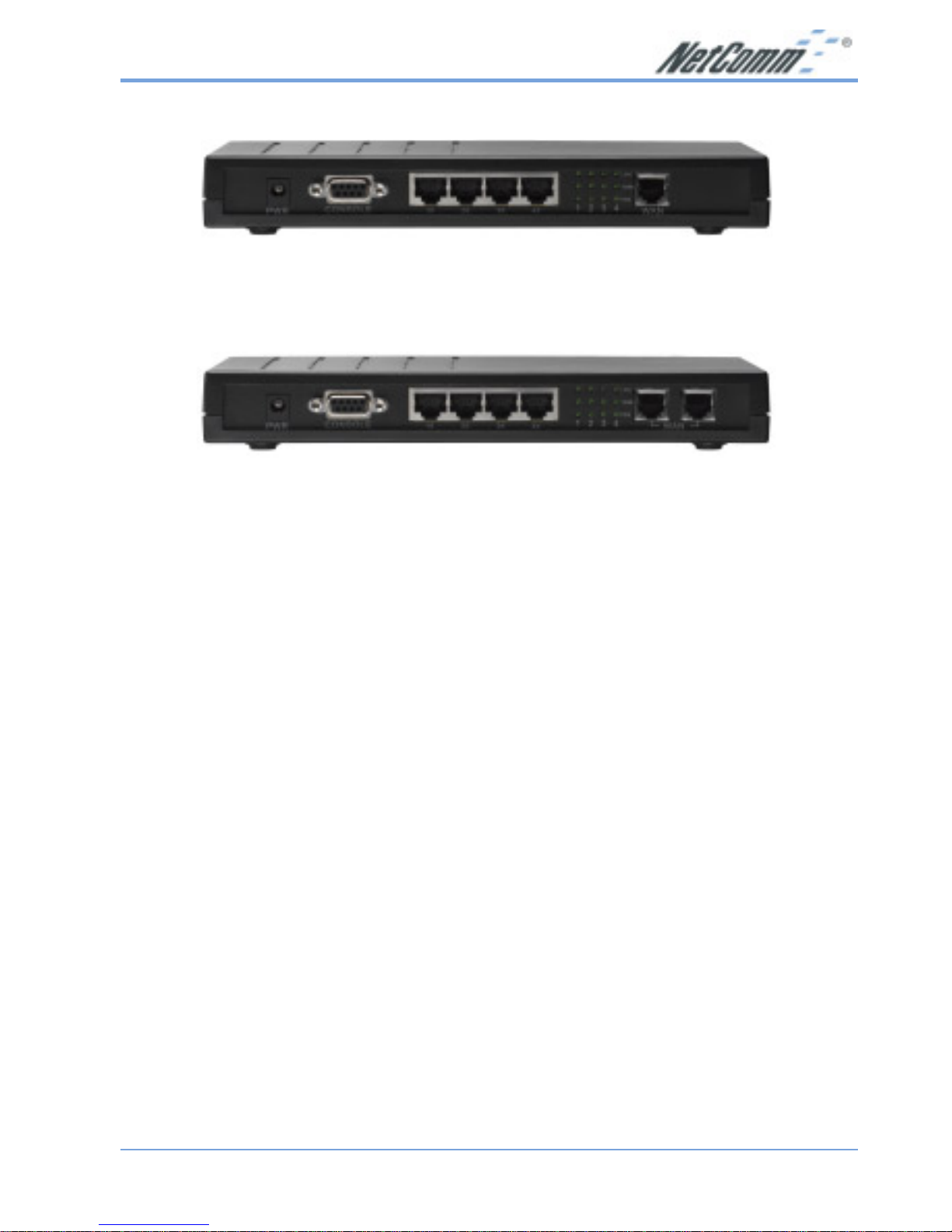
Rear Panel
NB702 Rear View
NB704 Rear View
Label Description
PWR DC-inlet for AC Adapter.
CONSOLE Serial port; connect to an ASCII data terminal.
1X ~ 4X Four RJ-45 ports; connect to a PC or LAN.
LINK LINK LED indicates a specific port is connected.
100M 100M LED: ON indicates 100M data transferring,
OFF indicates 10M data transferring.
FDX FDX LED: ON indicates full-duplex, OFF indicates
half-duplex
WAN RJ-11 port; connect to the SHDSL outlet
(Note: The NB704 has two WAN ports)
Page 10
www.netcomm.com.au Rev. 1 - YML689
Page 10 NB702/NB704 User Guide
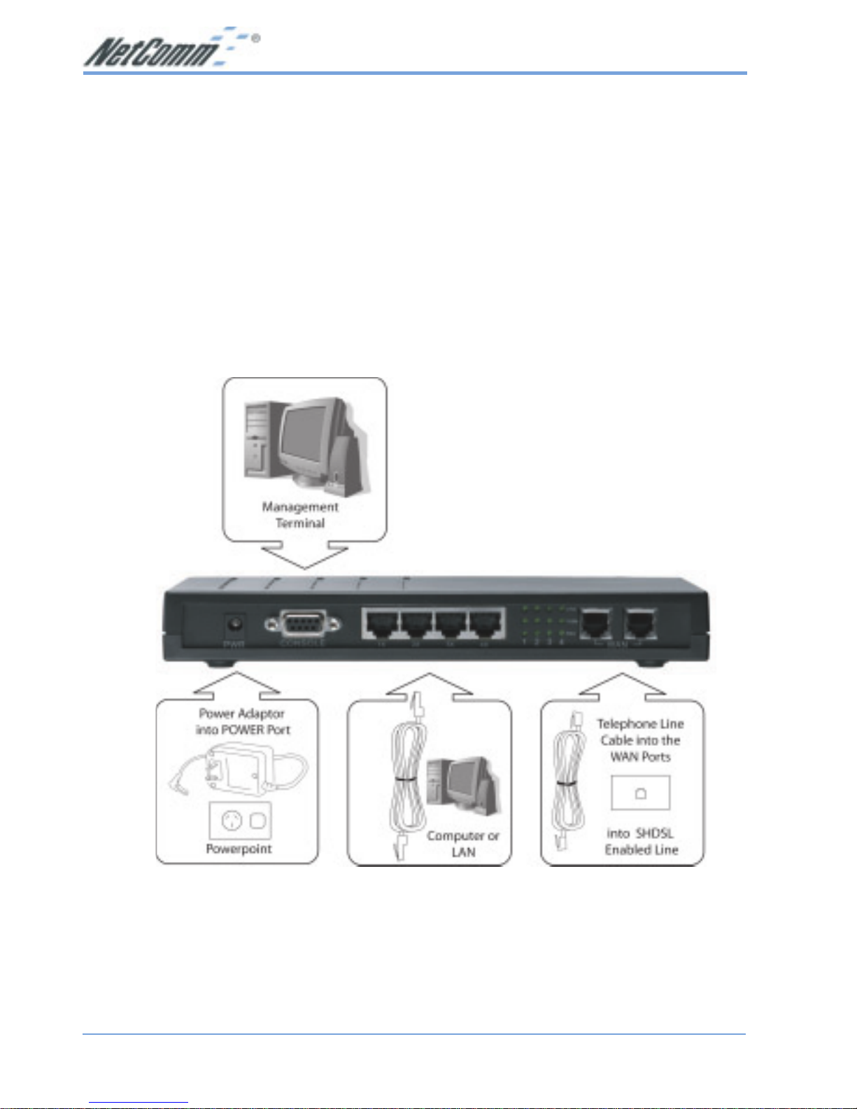
VI. Hardware Installation for the NB702/NB704
1. Connect one end of the RJ-11 cable into the WAN port of the NB702/NB704, and
the other end into the SHDSL wall outlet.
2. Connect one end of the RJ-45 cable into one of the RJ-45 ports of the NB702/
NB704, and the other end into your PC or LAN.
3. Plug in the AC adapter into the AC power socket, and connect the DC jack into
the PWR inlet of the NB702/NB704.
Note: Use a 9-pin RS-232 cable (not supplied) to connect the Console port to the PC
with data terminal emulation software (Hyper Terminal) installed. If you wish to
manage the NB702/NB704 via a serial Interface.
Note: The above example displays the NB704.
Page 11

Rev. 1 - YML689 www.netcomm.com.au
NB702/NB704 User Guide Page 11
VII. Management
Console Port (Serial) Use a the RS-232 cable to connect the NB702/
NB704 to a serial console terminal or a PC
running a terminal emulation program, such as
Hyper Terminal. (For further details, See Chapter
3: Command Line Interface)
Local Ethernet Port (Telnet) Connect the Ethernet port to your local
area network or directly to a PC, “telnet” the
NB702/NB704 from any workstation in the
LAN. The default local Ethernet IP address is
“192.168.1.1”.
Local Ethernet Port (Web Browser) Connect the Ethernet port to
your local area network or directly to a PC.
Launch your web browser and enter default local
Ethernet IP address “192.168.1.1” into the
address bar.
ADSL Port from Remote Site While the ADSL connection is in service, you
may remotely “telnet” the NB702/NB704 from a
workstation connected to the CO equipment.
Note: As operating an SHDSL device requires technical know-how and experience. It
is recommended that only qualified technical staff manage the NB702/NB704.
Therefore, password authentication is required when you enter the command line
and web interface. See the Default Values section to obtain the password.
Page 12

www.netcomm.com.au Rev. 1 - YML689
Page 12 NB702/NB704 User Guide
VI I I . Default Values
The NB702/NB704 is pre-configured with the following parameters; you may also reload the default parameters by typing Restore in the command line interface. (For
further details, See Chapter 3: Command Line Interface)
Default mode: Bridge
User Name: N/A
Password: admin
Bridge mode setting
Ethernet (local) IP: 192.168.1.1
Subnet mask: 255.255.255.0
Full Duplex: Disable
Protocol: RFC1483, Bridge Mode
VPI/VCI: 1/32
Class (QoS): UBR
Spanning tree: Disable
Packet filter: Any
G.SHDSL setting
Terminal: CPE
Rate mode: Adaptive
Annex: Annex A
Router mode setting
Ethernet (local) IP: 192.168.1.1
Subnet mask: 255.255.255.0
Full Duplex: Disable
DHCP server: Disable
DNS Relay: Disable
Serial Port Properties
Bit per second: 9600
Data bits: 8
Stop bits: 1
Parity bits: None
Flow Control: None
Terminal Emulation: VT100
Page 13

Rev. 1 - YML689 www.netcomm.com.au
NB702/NB704 User Guide Page 13
IX. Software Upgrade
You may easily upgrade the NB702/NB704 embedded software by obtaining the
compressed upgrade kit from the service provider then following the steps:
■ Extract the ZIP file for updated firmware
■ Connect the NB702/NB704 via the local Ethernet port or remote ADSL link, make
sure that the NB702/NB704 Ethernet IP address and your terminal are properly
configured so that you can successfully “ping” the NB704. The default local IP
address is 192.168.1.1.
■ Under the DOS prompt, execute the command “xupgrade <IP address of NB702/
NB704>”, for instance “xupgrade 192.168.1.1”.
■ This upgrading process may last as long as 60 seconds.
■ Then reboot the NB702/NB704 with new software.
Page 14

www.netcomm.com.au Rev. 1 - YML689
Page 14 NB702/NB704 User Guide
Chapter 2 - Web Management Interface
I. Overview
The W eb management is provided in order to manage NB702/NB704 device as easily
as possible. It provides a very user-friendly configuration and graphical interface
through a web platform. You may configure a bridge or a router function to
accommodate your device need. In the section below , each configuration item will be
described in detail.
II. Preparation
1. Please refer the hardware installation procedure in Chapter 1 to install NB702/
NB704.
2. You should configure the PC to the same IP subnet as the NB702/NB704.
Example:
NB704: 192.168.1.1
Y our PC: 192.168.1.x
3. Connect your PC to NB702/NB704 via an Ethernet cable.
4. Launch the Web browser (IE or Netscape), and enter the default IP address
192.168.1.1 into the address bar to access the web management page.
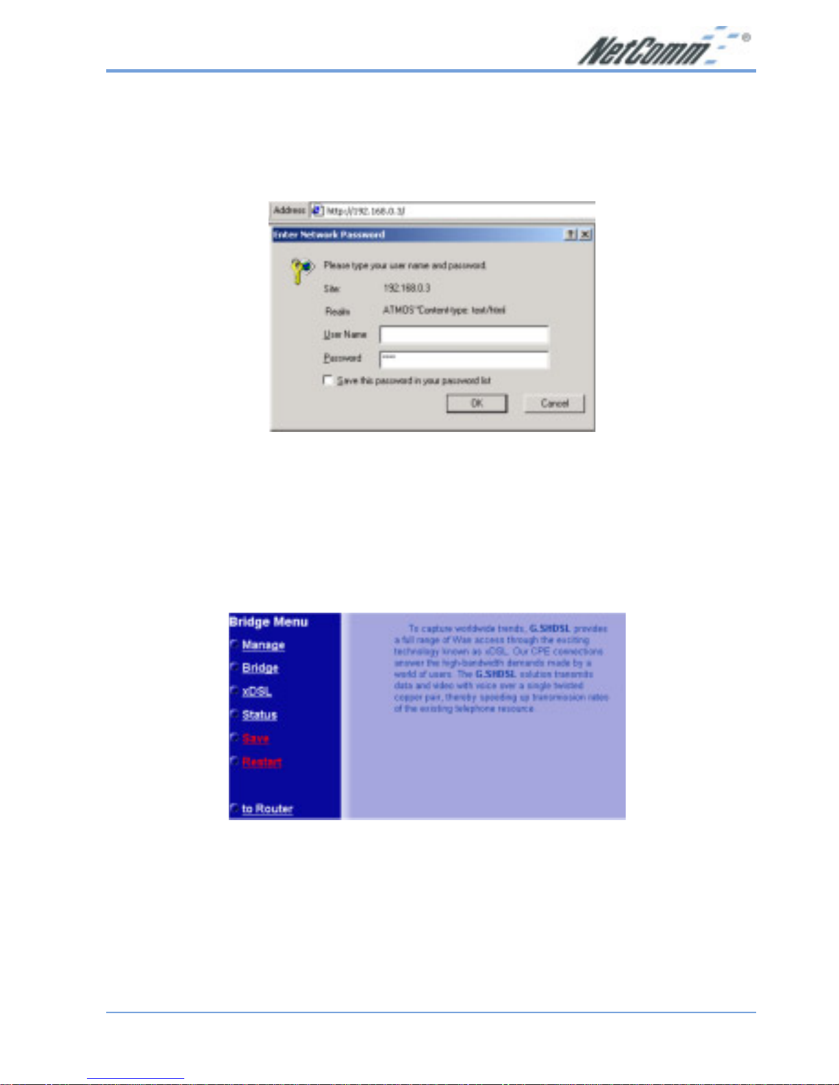
5. The Enter Network Password dialog box will popup first.
Note1: Some commands or settings shown in this manual may not be available
in the NB702 as it only supports 2 wire SHDSL .
Commands not currently supported in the NB702 are: ipoa, pppoa,
pppoe, rtable.
Note2: You should change the default admin password of your router before you
connect it to the internet or your network.
Note3: When using NAT/PAT a 'Portforward' or 'Incoming Table' entry will be
automatically generated for port 23 (Telnet). This will allow you to log-in
from the WAN side of the NB702/4. If you do not want to allow Telnet
service via the WAN port (Internet) you should delete the table entry for
port 23.
Page 15
Rev. 1 - YML689 www.netcomm.com.au
NB702/NB704 User Guide Page 15
1. Login
The window Enter Network password will pop up while starting the configuration.
With the window active, leave the User Name text box blank, and enter "admin" as the
Password, and then click on the OK button.
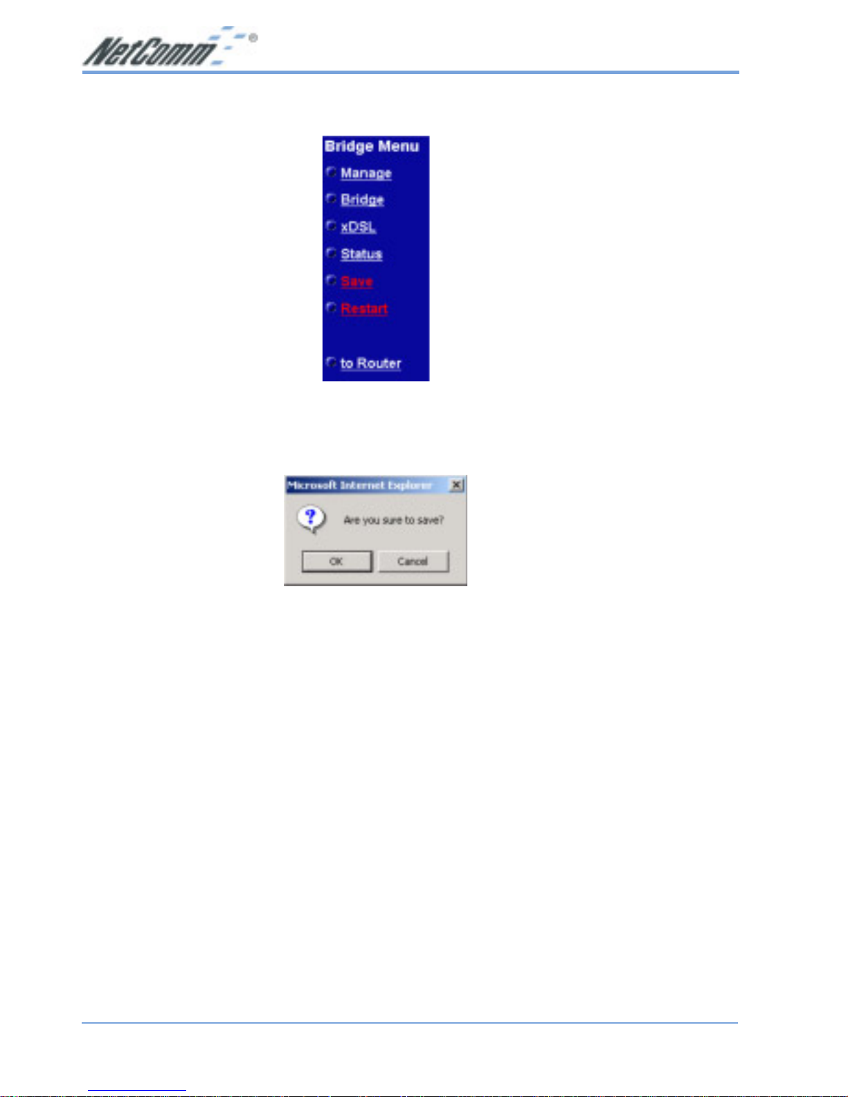
2. Bridge Mode Configuration
By default, the NB702/NB704 is configured in bridge mode. This section describes the
steps involved in setting up the NB702/NB704 as a bridge. The links on the
navigation bar are: Manage, Bridge, xDSL, Status, Save, and Restart. Each one is
described in the next few sections.
Page 16
www.netcomm.com.au Rev. 1 - YML689
Page 16 NB702/NB704 User Guide
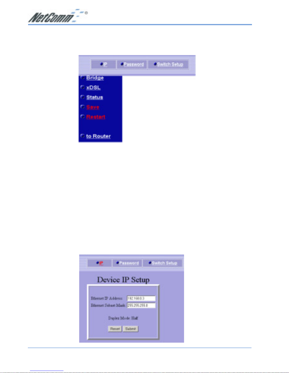
2.1 Manage
Click on the Manage link in the navigation bar.
You will then see three options: IP, Password, and Switch Setup. Each one is described
below.
2.1.1 IP Setup
Click on the IP link on the top of the page. You will then see the Device IP Setup
table. On this page you can change the IP address and subnet mask of the NB702/
NB704.
Ethernet IP Address: Enter the IP address of this device.
Ethernet Subnet Mask: Enter the subnet mask for the IP address.
Click on the Submit button to complete the configuration. You will then see a
confirmation screen.
Page 17
Rev. 1 - YML689 www.netcomm.com.au
NB702/NB704 User Guide Page 17
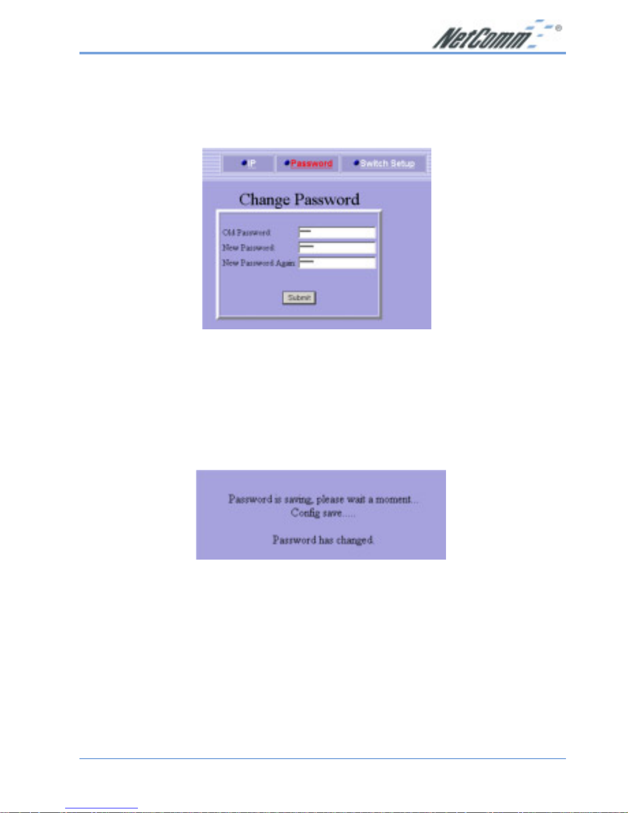
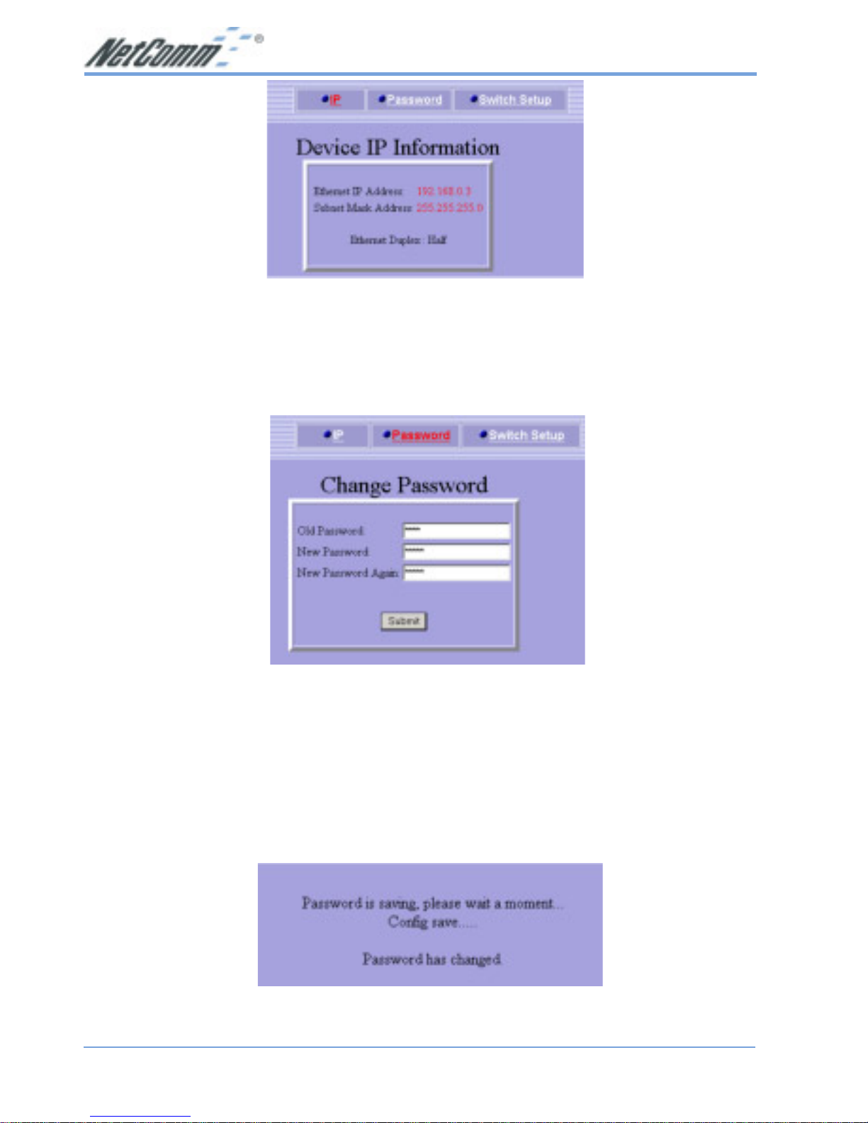
2.1.2 Password Setup
Click on the Password link on the top of the page. You will then see the Change
Password table. On this page you can change the password used to log into the
NB702/NB704.
Old Password: Enter the old password of the device.
New Password: Enter the new password.
New Password Again: Re-type the new password
Click on the Submit button to complete the configuration. You will then see a
confirmation message.
Page 18
www.netcomm.com.au Rev. 1 - YML689
Page 18 NB702/NB704 User Guide
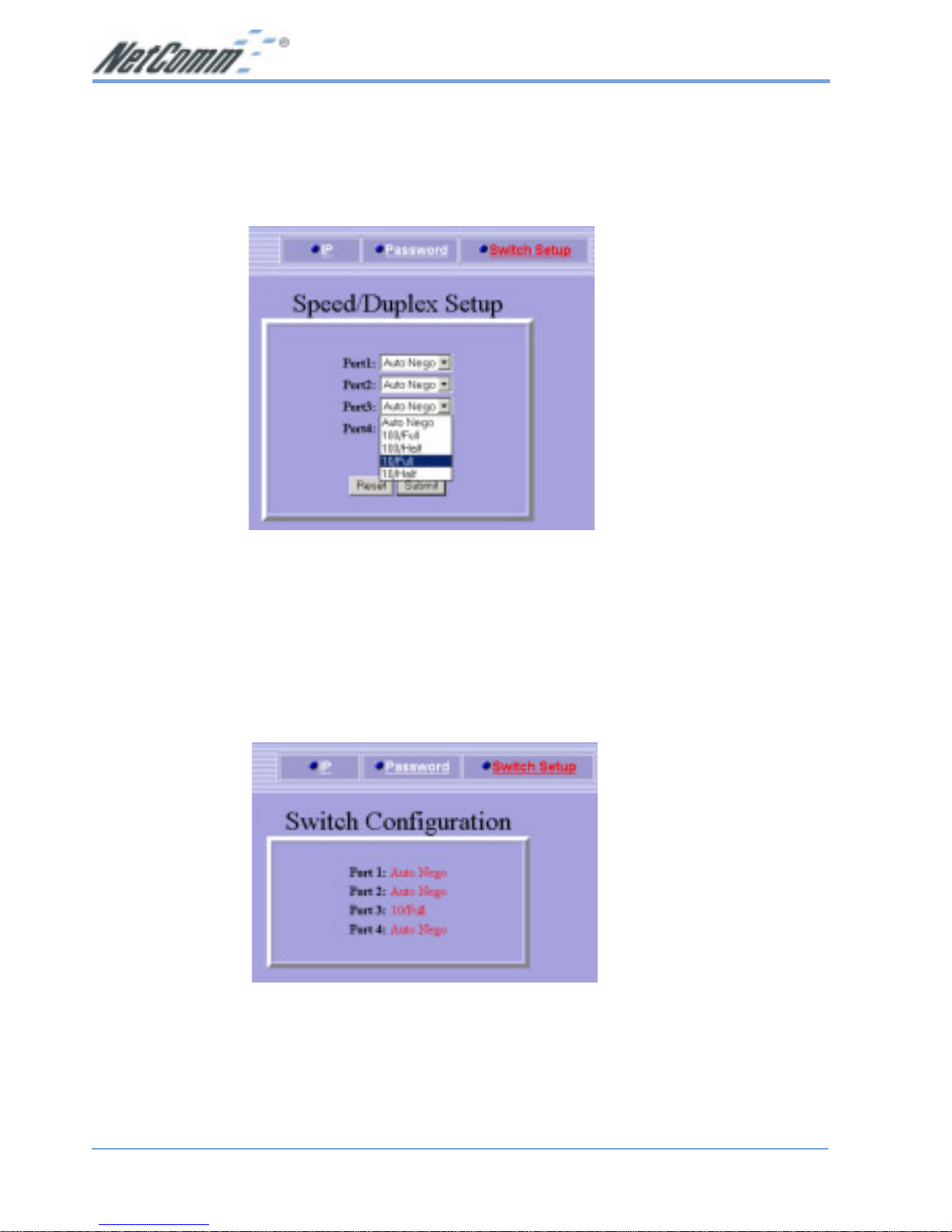
2.1.3 Switch Setup
Click on the Switch Setup link on the top of the page. You will then see the Speed/
Duplex table. On this page you can change the speed and duplex on individual ports of
the NB702/NB704.
Select a port number.
From the drop down list select: Auto-nego, 100/Full, 100/Half, 10/Full, or 10/Half.
Click on the Submit button to complete the configuration. You will then see a
confirmation screen.
Page 19

Rev. 1 - YML689 www.netcomm.com.au
NB702/NB704 User Guide Page 19
2.2 Bridge
Click on the Bridge link in the navigation bar.
You will then see the RFC 1483 link, which is described below.
2.2.1 RFC 1483
Click on the RFC 1483 link on the top of the page. You will then see the RFC 1483
Bridge Setup table. On this page you can create up to 8 VPI/VCI channels and
configure its QoS, encapsulation, packet filter, and spanning tree.
Enable: Place a check in this box if you would like to enable
the settings in that row.
Page 20
www.netcomm.com.au Rev. 1 - YML689
Page 20 NB702/NB704 User Guide
VPI: Enter the VPI value that you received from your ISP.
VCI: Enter the VCI value that you received from your ISP.
QoS: Select a Quality of Service from the drop down list,
options available are: UBR, CBR, VBR-nrt, VBR –rt.
LLC/VCMUX: Select an encapsulation method from the drop down
list, options available are: LLC and VCMUX.
Pkt Filter: Select a packer filter from the drop down list, options
available are: IP, PPPoE, IGMP, or None.
Spanning Tree Enable: If you would like the connection to use spanning tree,
place a check in this box.
Click on the Submit button to complete the configuration. You will then see a
confirmation screen.
Page 21
Rev. 1 - YML689 www.netcomm.com.au
NB702/NB704 User Guide Page 21
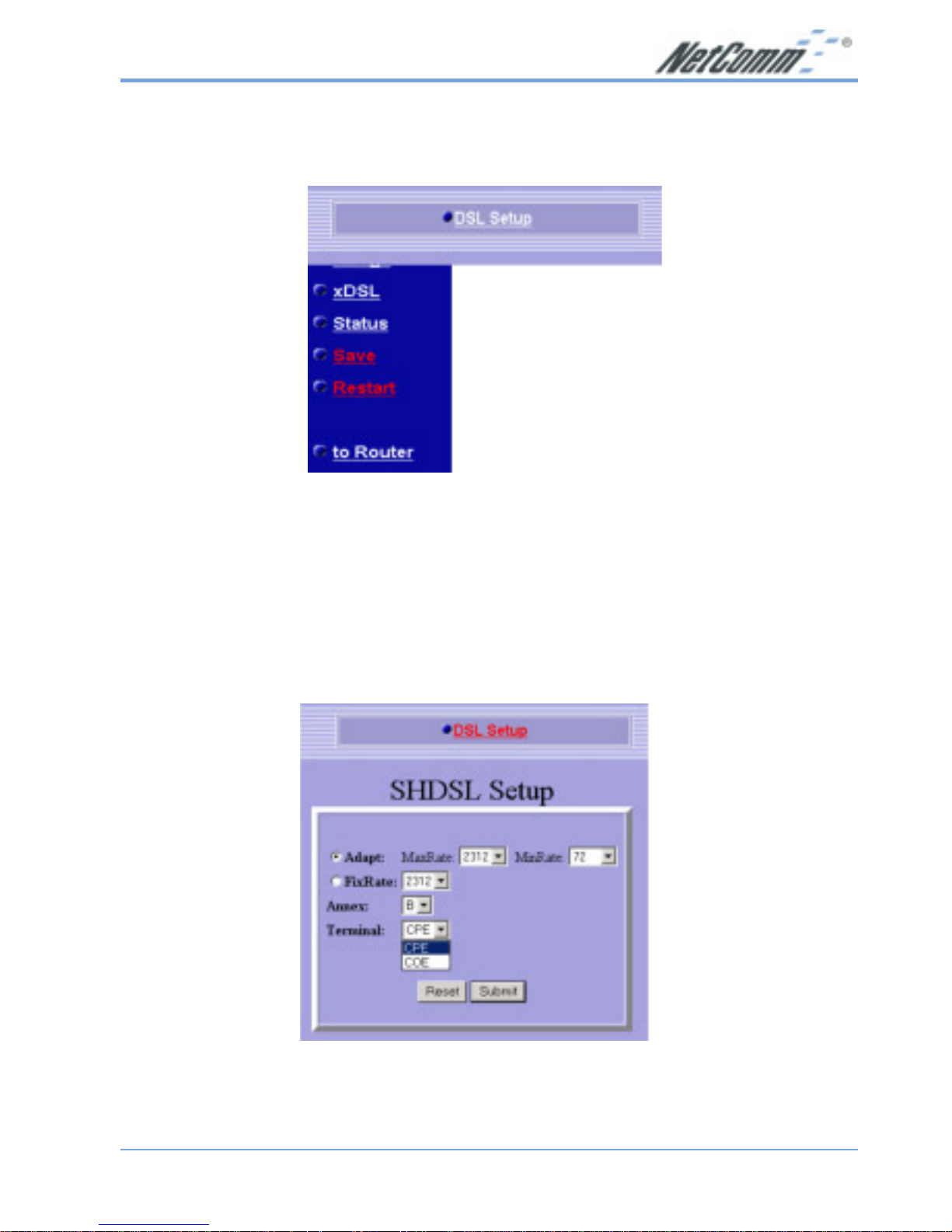
2.3 xDSL
Click on the xDSL link in the navigation bar .
You will then see the DSL Setup link, which is described below.
2.3.1 DSL Setup
Click on the DSL Setup link on the top of the page. You will then see the SHDSL
Setup table. On this page you can modify the line rate, annex standard, and terminal
type of the NB702/NB704.
Adapt: If you would like to use adaptive line rate, then select
MaxRate and MinRate from the drop down list.
Page 22
www.netcomm.com.au Rev. 1 - YML689
Page 22 NB702/NB704 User Guide
FixRate: If you would like to use a fixed line rate, then select a
FixRate from the drop down list.
Annex: Select A or B from the drop down list.
Terminal: Select a terminal type from the drop down list, CPE
or COE.
Click on the Submit button to complete the configuration. You will then see a
confirmation screen.
Page 23
Rev. 1 - YML689 www.netcomm.com.au
NB702/NB704 User Guide Page 23
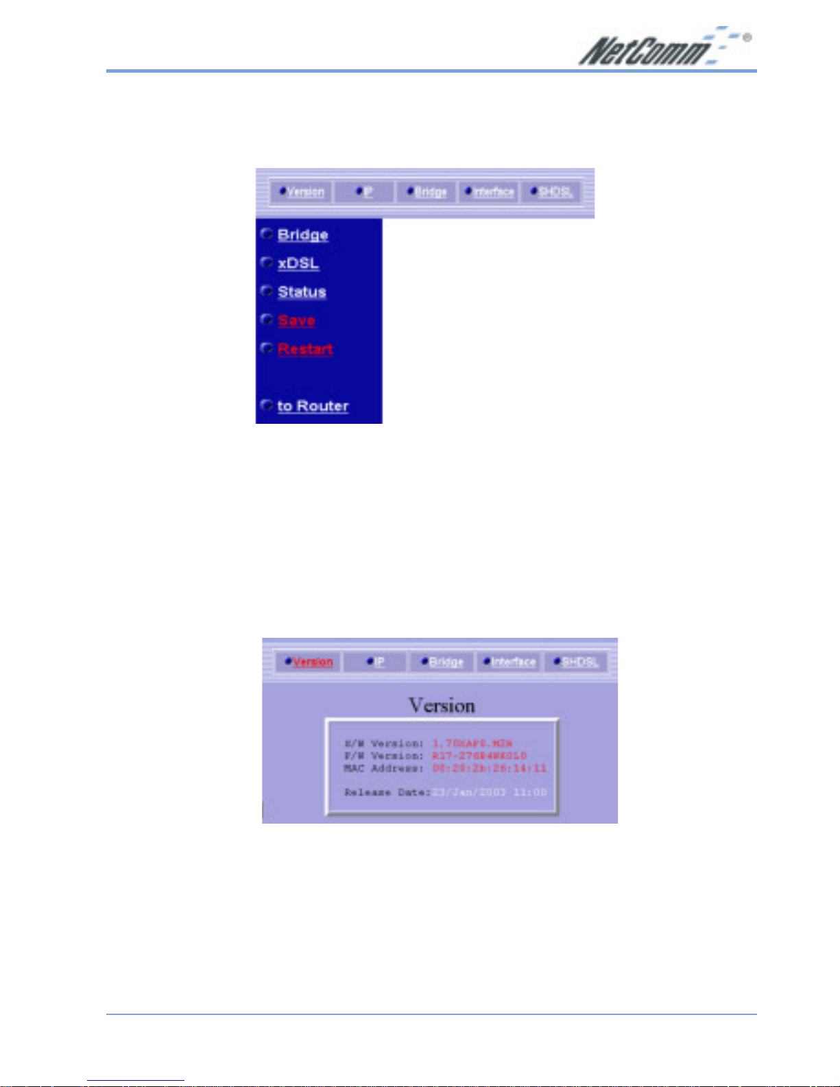
2.4 Status
Click on the Status link in the navigation bar .
You will then see five options: V ersion, IP, Bridge, Interface, and SHDSL. Each one is
described below .
2.4.1 V ersion
Click on the Version link on the top of the page. You will then see the Version table
that displays the software version, firmware version, MAC address, and release date
of the NB702/NB704.
Page 24

www.netcomm.com.au Rev. 1 - YML689
Page 24 NB702/NB704 User Guide
2.4.2 IP
Click on the IP link on the top of the page. You will then see the Device IP
Information table that displays the Ethernet IP address, subnet mask, and duplex of
the NB702/NB704.
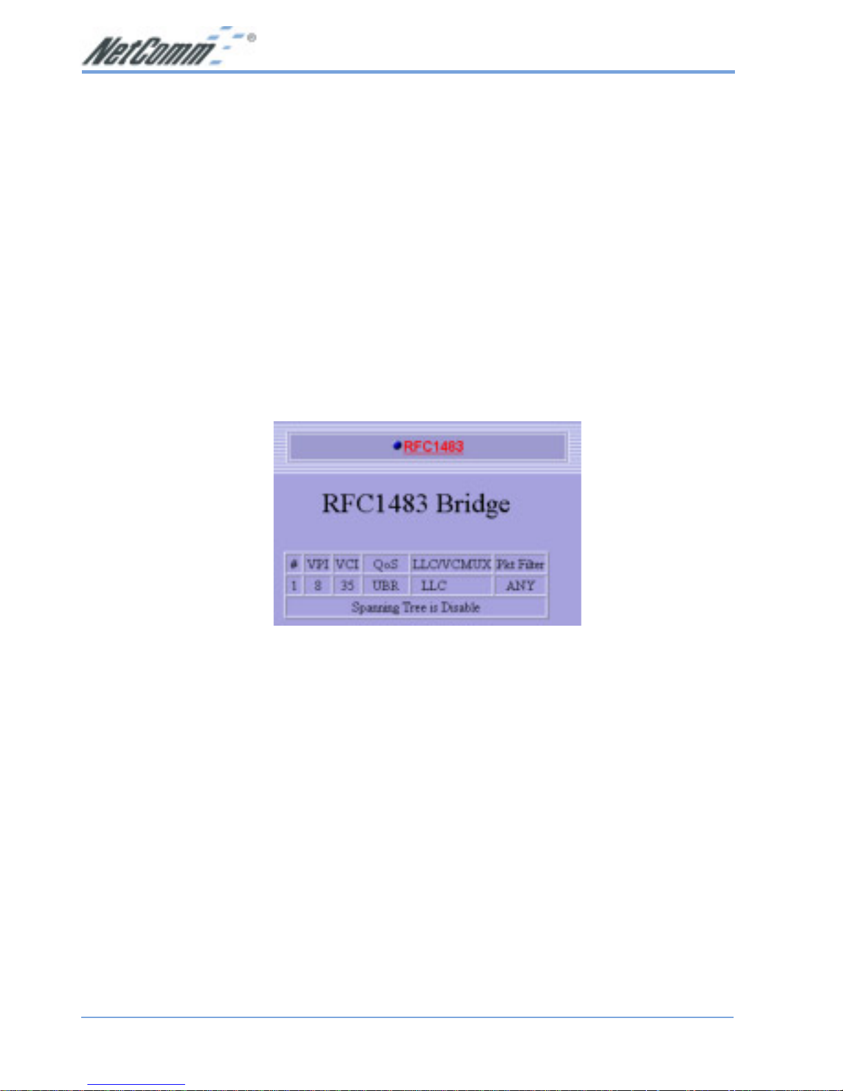
2.4.3 Bridge
Click on the Bridge link on the top of the page. You will then see the RFC 1483 Bridge
table that displays the VPI/VCI values, QoS, encapsulation method, and packet filter
of the NB702/NB704.
Page 25
Rev. 1 - YML689 www.netcomm.com.au
NB702/NB704 User Guide Page 25
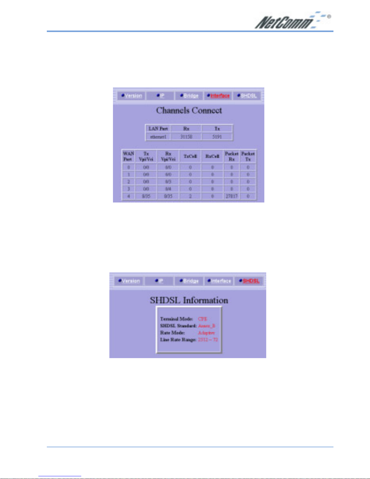
2.4.4 Interface
Click on the Interface link on the top of the page. You will then see the Channels
Connect table that displays the transfer and receive values of the Ethernet and WAN
ports of the NB702/NB704.
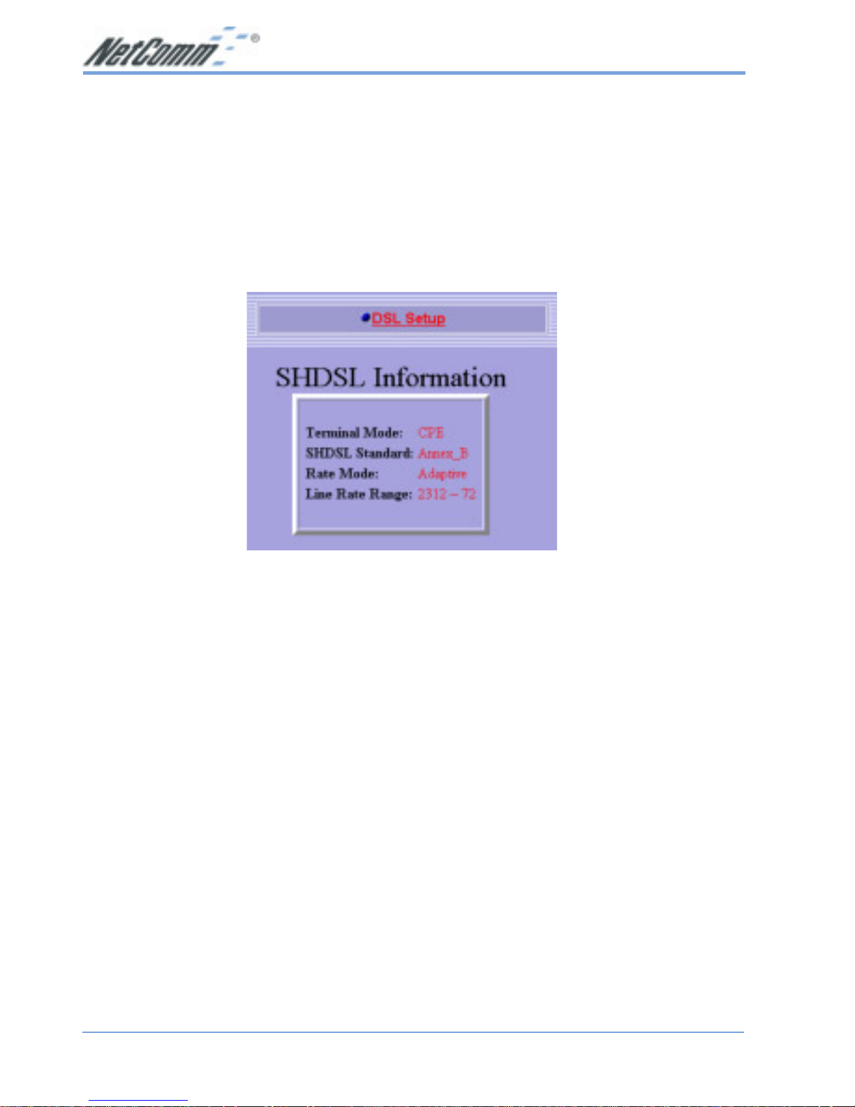
2.4.5 SHDSL
Click on the SHDSL link on the top of the page. You will then see the SHDSL
Information table that displays the terminal mode, SHDSL standard, rate mode, and
line rate range of the NB702/NB704.
Page 26
www.netcomm.com.au Rev. 1 - YML689
Page 26 NB702/NB704 User Guide
2.5 Save
In order to save the changes to the NB702/NB704, you must click on the Save link on
the navigation bar. You will then see the following message appear.
Click on the OK button to save the changes.
Page 27
Rev. 1 - YML689 www.netcomm.com.au
NB702/NB704 User Guide Page 27
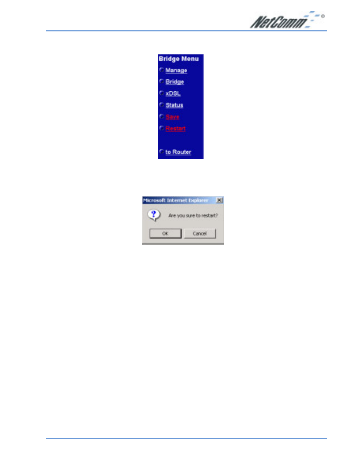
2.6 Restart
In order to restart the NB702/NB704, you must click on the Restart link on the
navigation bar. You will then see the following message appear .
Click on the OK button to restart the NB702/NB704.
Page 28

www.netcomm.com.au Rev. 1 - YML689
Page 28 NB702/NB704 User Guide
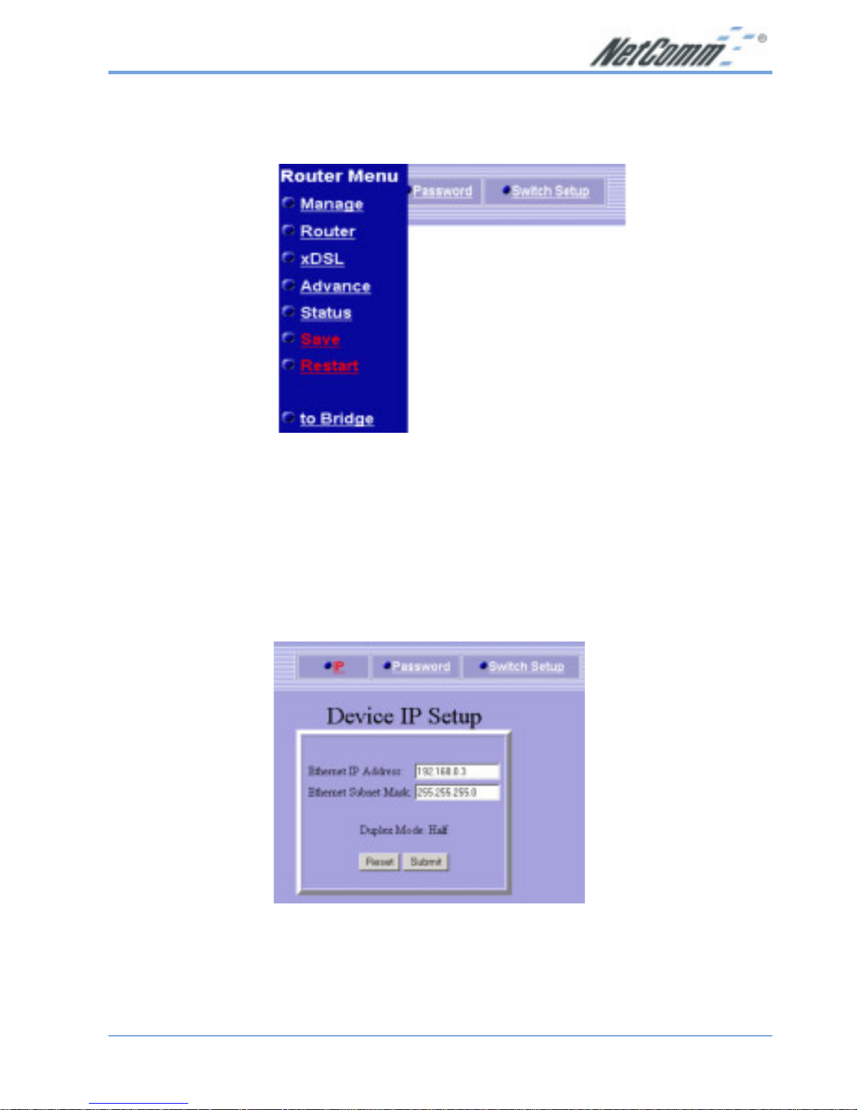
3. Router Mode Configuration
By default, the NB702/NB704 is configured in bridge mode. In order to switch to
Router mode, click on the to Router link at the bottom of the navigation bar. You will
then see the following screen.
This section describes the steps involved in setting up the NB702/NB704 as a router.
The links on the navigation bar are: Manage, Router, xDSL, Advance, S tatus, Save, and
Restart. Each one is described in the next few sections.
Page 29
Rev. 1 - YML689 www.netcomm.com.au
NB702/NB704 User Guide Page 29
3.1 Manage
Click on the Manage link in the navigation bar .
You will then see three options: IP, Password, and Switch Setup. Each one is described
below.
3.1.1 IP Setup
Click on the IP link on the top of the page. You will then see the Device IP Setup
table. On this page you can change the IP address and subnet mask of the NB702/
NB704.
Ethernet IP Address: Enter the IP address of this device.
Ethernet Subnet Mask: Enter the subnet mask for the IP address.
Click on the Submit button to complete the configuration. You will then see a
confirmation screen.
Page 30
www.netcomm.com.au Rev. 1 - YML689
Page 30 NB702/NB704 User Guide
3.1.2 Password Setup
Click on the Password link on the top of the page. You will then see the Change
Password table. On this page you can change the password used to log into the
NB702/NB704.
Old Password: Enter the old password of the device.
New Password: Enter the new password.
New Password Again: Re-type the new password
Click on the Submit button to complete the configuration. You will then see a
confirmation message.
Page 31

Rev. 1 - YML689 www.netcomm.com.au
NB702/NB704 User Guide Page 31
3.1.3 Switch Setup
Click on the Switch Setup link on the top of the page. You will then see the Speed/
Dublex table. On this page you can change the speed and duplex on individual ports of
the NB702/NB704.
Select a port number .
From the drop down list select: Auto-nego, 100/Full, 100/half, 10/Full, or 10/Half.
Click on the Submit button to complete the configuration. You will then see a
confirmation screen.
Page 32

www.netcomm.com.au Rev. 1 - YML689
Page 32 NB702/NB704 User Guide
3.2 Router
Click on the Router link in the navigation bar.
You will then see four options: RFC1483, PPPoA, IPoA, and PPPoE. You may
configure each connection by first clicking on the link above. Each configuration is
described in the next few sections.
Page 33

Rev. 1 - YML689 www.netcomm.com.au
NB702/NB704 User Guide Page 33
3.2.1 RFC 1483
Click on the RFC 1483 link on the top of the page. You will then see the RFC 1483
Router Setup table. On this page you can create up to 6 VPI/VCI channels and
configure its QoS, encapsulation, RIP, and WAN IP.
Enable: Place a check in this box if you would like to enable
the settings in that row.
VPI: Enter the VPI value that you received from your ISP.
VCI: Enter the VCI value that you received from your ISP.
QoS: Select a Quality of Service from the drop down list,
options available are: UBR, CBR, VBR-nrt, VBR –rt.
RIP: Select an RIP version from the drop down list,
options available are: none, V1, V2, or V1&V2.
WAN IP: Enter the IP address of the WAN interface.
Mask: Enter the subnet mask for the WAN IP.
Click on the Submit button to complete the configuration. You will then see a
confirmation screen.
Page 34

www.netcomm.com.au Rev. 1 - YML689
Page 34 NB702/NB704 User Guide
3.2.2 PPPoA (PPP over ATM)
Click on the PPPoA link on the top of the page. You will then see the PPPoA Setup
table. On this page you can create your PPPoA connection based on your ISPs
settings.
Enable: Place a check in this box if you would like to enable
the settings in that row.
VPI: Enter the VPI value that you received from your ISP.
VCI: Enter the VCI value that you received from your ISP.
QoS: Select a Quality of Service from the drop down list,
options available are: UBR, CBR, VBR-nrt, VBR –rt.
RIP: Select an RIP version from the drop down list,
options available are: none, V1, V2, or V1&V2.
Authentication: Select None, PAP, or CHAP from the drop down list.
User ID: Enter the username provided by your ISP.
Password: Enter the password provided by your ISP.
Confirm: Re-type the password provided by your ISP.
WebEchoInterval: Leave this value set to 0, unless your ISP tells you
otherwise.
Page 35

Rev. 1 - YML689 www.netcomm.com.au
NB702/NB704 User Guide Page 35
Click on the Submit button to complete the configuration. You will then see a
confirmation screen.
3.2.3 IPoA (IP over Ethernet)
Click on the IPoA link on the top of the page. You will then see the IPoA Setup table.
On this page you can create your IPoA connection based on your ISPs settings.
Enable: Place a check in this box if you would like to enable
the settings in that row.
VPI: Enter the VPI value that you received from your ISP.
VCI: Enter the VCI value that you received from your ISP.
QoS: Select a Quality of Service from the drop down list,
options available are: UBR, CBR, VBR-nrt, VBR –rt.
Page 36

www.netcomm.com.au Rev. 1 - YML689
Page 36 NB702/NB704 User Guide
WAN IP: Enter the IP address of the WAN interface.
Mask: Enter the subnet mask for the WAN IP.
Gateway: Enter the IP address of the gateway.
RIP: Select an RIP version from the drop down list,
options available are: none, V1, V2, or V1&V2.
Click on the Submit button to complete the configuration. You will then see a
confirmation screen.
Page 37

Rev. 1 - YML689 www.netcomm.com.au
NB702/NB704 User Guide Page 37
3.2.4 PPPoE (PPP over Ethernet)
Click on the PPPoE link on the top of the page. You will then see the PPPoE Setup
table. On this page you can create your PPPoE connection based on your ISPs
settings.
Enable: Place a check in this box if you would like to enable
the settings in that row.
VPI: Enter the VPI value that you received from your ISP.
VCI: Enter the VCI value that you received from your ISP.
QoS: Select a Quality of Service from the drop down list,
options available are: UBR, CBR, VBR-nrt, VBR –rt.
Authentication: Select None, PAP, or CHAP from the drop down list.
User ID: Enter the username provided by your ISP.
Password: Enter the password provided by your ISP.
Confirm: Re-type the password provided by your ISP.
WebEchoInterval: Leave this value set to 0, unless your ISP tells you
otherwise.
Click on the Submit button to complete the configuration. You will then see a confirmation
screen.
Page 38

www.netcomm.com.au Rev. 1 - YML689
Page 38 NB702/NB704 User Guide
3.3 xDSL
Click on the xDSL link in the navigation bar .
You will then see the DSL Setup link, which is described below.
3.3.1 DSL Setup
Click on the DSL Setup link on the top of the page. You will then see the SHDSL
Setup table. On this page you can modify the line rate, annex standard, and terminal
type of NB702/NB704.
Adapt: If you would like to use adaptive line rate, then select
MaxRate and MinRate from the drop down list.
Page 39

Rev. 1 - YML689 www.netcomm.com.au
NB702/NB704 User Guide Page 39
FixRate: If you would like to used a fixed line rate, then select a
FixRate from the drop down list.
Annex: Select A or B from the drop down list.
Terminal: Select a terminal type from the drop down list, CPE or COE.
Click on the Submit button to complete the configuration. You will then see a
confirmation screen.
Page 40

www.netcomm.com.au Rev. 1 - YML689
Page 40 NB702/NB704 User Guide
3.4 Advance
Click on the Advance link in the navigation bar.
You will then see four options: DHCP, NAT, Routing Table, and DNS Relay. You may
configure each connection by first clicking on the link above. Each configuration is
described in the next few sections.
3.4.1 DHCP
Click on the DHCP link on the top of the page. You will then see the DHCP Server
Setup table. On this page you can modify the DHCP Server settings of NB704.
Page 41

Rev. 1 - YML689 www.netcomm.com.au
NB702/NB704 User Guide Page 41
Enable: Place a check in this box if you would like to enable the
DHCP Server.
Range 1 Start IP Address: Enter the IP address from which the NB702/NB704 can
start assigning IP address.
Range 1 End IP Address: Enter the IP address that is the last one that the NB702/
NB704 will assign.
Range 2 Start IP Address: Enter a second range if required.
Range 2 End IP Address: Enter a second range if required.
Primary DNS Address: Enter the IP address of the primary DNS server.
Secondary DNS Address: Enter the IP address of the secondary DNS server (not
required).
Default Lease Time: Enter the max number of seconds you would like the IP
addresses assigned.
Click on the Submit button to complete the configuration. You will then see a
confirmation screen.
Page 42

www.netcomm.com.au Rev. 1 - YML689
Page 42 NB702/NB704 User Guide
3.4.2 NA T (Network Address Translation)
Click on the NAT (Network Address Translation) link on the top of the page. You will
then see the NAT Setup table.
You may enable NAT one any existing interface by placing a check in the box next to
the interface name. Then click on the Submit button to confirm the configuration.
You can also set up PAT (Port Address Translation) by clicking on the PAT link next
to the interface name. Refer to the next section if you would like to configure PAT.
Note: When using NAT/PAT a 'Portforward' or 'Incoming Table' entry will be
automatically generated for port 23 (Telnet). This will allow you to log-in
from the WAN side of the NB702/4. If you do not want to allow Telnet
service via the WAN port (Internet) you should delete the table entry for
port 23.
Page 43

Rev. 1 - YML689 www.netcomm.com.au
NB702/NB704 User Guide Page 43
3.4.2.1 P A T (Port Address T ranslation)
To set up PAT (Port Address Translation) click on the PAT link next to the interface
name on the NAT Setup table. You will then see the PAT Incoming Table.
Port: Enter the port number that you would like to filter.
Protocol: Select a protocol from the drop down list (TCP or UDP).
Server IP: Enter the IP address of the server that will receive the
packets.
Click on the Submit button to complete the configuration. You will then notice that
your configuration has been added to the list.
Page 44

www.netcomm.com.au Rev. 1 - YML689
Page 44 NB702/NB704 User Guide
3.4.3 Routing Table
Click on the Routing Table link on the top of the page. You will then see the Routing
T able Setup page. On this page you can add or remove routing table entries.
Destination IP: Enter the IP address of the destination router.
Subnet Mask: Enter the subnet mask of that IP address.
Gateway IP: Select a gateway IP from the drop down list.
Click on the Submit button to complete the configuration. You will then notice that
your configuration has been added to the list.
Page 45

Rev. 1 - YML689 www.netcomm.com.au
NB702/NB704 User Guide Page 45
3.4.4 DNS Relay
Click on the DNS Relay link on the top of the page. You will then see the DNS Relay
Setup page. On this page, you add the DNS Server’s IP address.
DNS Server IP Address: Enter the IP address of the DNS Server.
Retry Time: Enter the number of times that you would like the
NB702/NB704 to try to connect to the DNS Server if
the connection fails.
Click on the Submit button to complete the configuration. You will then see a
confirmation screen.
Page 46

www.netcomm.com.au Rev. 1 - YML689
Page 46 NB702/NB704 User Guide
3.5 Status
Click on the Status link in the navigation bar .
You will then see five options:
■ V ersion,
■ IP,
■ Router,
■ Advance,
■ Interface, and
■ SHDSL.
Refer to the following descriptions.
3.5.1 Version
Click on the Version link on the top of the page. You will then see the Version table
that displays the software version, firmware version, MAC address, and release date
of the NB702/NB704.
Page 47

Rev. 1 - YML689 www.netcomm.com.au
NB702/NB704 User Guide Page 47
3.5.2 IP
Click on the IP link on the top of the page. You will then see the Device IP
Information table that displays the Ethernet IP address, subnet mask, and duplex of
the NB702/NB704.
3.5.3 Router
Click on the Router link on the top of the page. You will then see the Router Protocol
Status Options. Click on the appropriate protocol to view its status, or click on the
Router link in the navigation bar for configuration.
3.5.4 Advance
Click on the Advance link on the top of the page. You will then see the Advanced
Status Options. Click on the appropriate option to view its status, or click on the
Advance link in the navigation bar for configuration.
Page 48

www.netcomm.com.au Rev. 1 - YML689
Page 48 NB702/NB704 User Guide
3.5.5 Interface
Click on the Interface link on the top of the page. You will then see the Channels
Connect table that displays the transfer and receive values of the Ethernet and WAN
ports of the NB702/NB704.
3.5.6 SHDSL
Click on the SHDSL link on the top of the page. You will then see the SHDSL
Information table that displays the terminal mode, SHDSL standard, rate mode, and
line rate range of the NB702/NB704.
Page 49

Rev. 1 - YML689 www.netcomm.com.au
NB702/NB704 User Guide Page 49
3.6 Save
In order to save the changes to the NB704, you must click on the Save link on the
navigation bar. You will then see the following message appear .
Click on the OK button to save the changes.
Page 50

www.netcomm.com.au Rev. 1 - YML689
Page 50 NB702/NB704 User Guide
3.7 Restart
In order to restart the NB702/NB704, you must click on the Restart link on the
navigation bar. You will then see the following message appear.
Click on the OK button to restart the NB702/NB704.
Page 51

Rev. 1 - YML689 www.netcomm.com.au
NB702/NB704 User Guide Page 51
Chapter 3 - Command Line Interface
I. CLI Commands
The next few sections in this chapter will describe the commands required to configure
the NB702/NB704 in bridge and router mode. The chapter is divided into three
sections.
1. Main Menu Commands: this section lists all the commands available and
describes the commands that are common in both bridge and router mode.
2. Bridge Mode Configuration: this section lists and describes all the commands
that are used for configuring the NB702/NB704 as a bridge.
3. Router Mode Configuration: this section lists and describes all the commands
that are used for configuring the NB702/NB704 as a router.
Note1: Some commands or settings shown in this manual may not be available
in the NB702 as it only supports 2 wire SHDSL .
Commands not currently supported in the NB702 are; ipoa, pppoa,
pppoe, rtable.
Note2: You should change the default admin password of your router before you
connect it to the internet or your network.
Note3: When using NAT/PAT a 'Portforward' or 'Incoming Table' entry will be
automatically generated for port 23 (Telnet). This will allow you to log-in
from the WAN side of the NB702/4. If you do not want to allow Telnet
service via the WAN port (Internet) you should delete the table entry for
port 23.
Page 52

www.netcomm.com.au Rev. 1 - YML689
Page 52 NB702/NB704 User Guide
II. Console Setup
Connect the RS-232 console port to an ASCII data terminal or a PC with Widows
serial Terminal mode of VT-100 (Hyper Terminal). To Start the Hyper-terminal,
follow the steps below.
1. Start "Hyper-terminal" program:
On Windows 98 or Windows NT:
Click on the Start button -> Programs -> Accessories -> Hyper Terminal Group -
> Double Click “Hypertrm.exe” -> Enter Connection Name -> Select Icon -> Click
OK
2. Select a COM port to communicate with the NB704:
Choose direct to COM1 or COM2 and click on OK
3. Set Port Properties:
Port Setting:
Bit per second: 9600
Data bits: 8
Stop bits: 1
Parity bits: None
Flow Control: None
Settings:
Function, arrow, and ctrl keys act as: Windows keys
Emulation: Auto-detect
Back-scroll buffer lines: 500
ASCII Setup: Echo typed characters locally
Line delay: 0 milliseconds
Character line feeds incoming line ends: enable
Page 53

Rev. 1 - YML689 www.netcomm.com.au
NB702/NB704 User Guide Page 53
1. Main Menu Commands
Type “?” followed by “>>” is used retrieve the list of commands to begin the
configuration. Type “home” to return to the main menu.
Command Syntax Description / Parameters
? >> ? Lists the commands available under the main menu
Default >> default Set all configuration to factory setting
Dnsrelay >> dnsrelay Entry to DNS Relay menu (See DNS Relay Menu
Commands for more details)
Ipoa >> ipoa Entry to IPoA menu [Router Mode Only] (See IPoA
Menu Commands for more details)
Lan >> lan Entry to Ethernet Menu (See LAN Menu Commands
for more details)
List >> list List status for enabled PVC
Manage >> manage Entry to Management menu (See Manage Menu
Commands for more details)
Mode >> mode Exit this menu and change modem mode
Pat >> pat Entry to P AT menu (See PAT Menu Commands for
more details)
Ping >> ping Ping IP for testing purpose
Pppoa >> pppoa Entry to PPPoA menu [Router Mode Only] (See PPPoA
Menu Commands for more details)
Pppoe >> pppoe Entry to PPPoE menu [Router Mode only] (See PPPoE
Menu Commands for more details)
Quick >> quick Quick setup
R1483 >> r1483 Training with DSLAM.
Entry to RFC1483 menu (See RFC1483 Menu
Commands for more details)
Restart >> restart Reboot modem
Rtable >> rtable Entry to Routing Table Menu [Router Mode Only] (See
Routing Table Menu Commands for more details)
Save >> save Save and restart modem
Shdsl >> shdsl Entry to SHDSL menu (See SHDSL Menu Commands
for more details)
Ver >> ver displays software version
Note: Commands not currently supported in the NB702 are: ipoa, pppoa,
pppoe, rtable
Page 54

www.netcomm.com.au Rev. 1 - YML689
Page 54 NB702/NB704 User Guide
DEFAULT
Set all configurations back to factory settings.
Syntax: default
>> default
The data set to default successfully.
>>
LIST
Lists the status for enabled PVCs. Includes the port, transfer, and receive packet
information.
Syntax: list
>> list
Port ethernet1 0: edd TxPkts: 1/0
RxPkts: 10/0
Port shdsl
0: oamloop TxPkts: 0/0 RxPkts: 0/0 TxVPI/VCI:
0/0 RxVPI/VCI: 0/0
1: oamloop TxPkts: 0/0 RxPkts: 0/0 TxVPI/VCI:
0/0 RxVPI/VCI: 0/0
2: oamloop TxPkts: 0/0 RxPkts: 0/0 TxVPI/VCI:
0/0 RxVPI/VCI: 0/3
3: oamloop TxPkts: 0/0 RxPkts: 0/0 TxVPI/VCI:
0/0 RxVPI/VCI: 0/4
4: bridge TxPkts: 7/0 RxPkts: 0/0 TxVPI/
VCI: 8/35 RxVPI/VCI: 8/35
MODE
Switch between bridge and router mode.
Syntax: mode
You will be prompted to choose between a bridge or
router mode. Type “b” for bridge or “r” for router.
The default mode is: bridge
>> mode
Please select bridge or router:(b/r,b) b
Current mode is bridge
>>
>> mode
Please select bridge or router:(b/r,b) r
Current mode is router
Page 55

Rev. 1 - YML689 www.netcomm.com.au
NB702/NB704 User Guide Page 55
PING
Allows you to PING an IP address for testing purposes.
Syntax: ping <ipaddress>
Example: ping 192.168.0.2
>> ping 192.168.0.2
Press 'ESC' to break
ip: ping - reply received from 192.168.0.2
ip: ping - reply received from 192.168.0.2
ip: ping - reply received from 192.168.0.2
RESTART
Reboots the modem.
Syntax: restart
>> restart
NBfs0ZSDRAM size = 0x800000
Booting...
System start...
password:
>>
SA VE
Saves the current configuration and reboots the modem.
Syntax: save
>> save
Saving configuration...
Configuration saved.
Updating flash filing system ...
done
NBfs0ZSDRAM size = 0x800000
Booting...
System start...
password:
Page 56

www.netcomm.com.au Rev. 1 - YML689
Page 56 NB702/NB704 User Guide
SHOW (Bridge Mode)
Displays the configuration of PVCs, Ethernet IP, Subnet mask, and Full Duplex.
Syntax: show
The configuration information will then be displayed.
This includes the following: Ethernet IP address,
subnet mask, auto-negotiation of full duplex: (enable,
disable), type of function, VPI/VCI values, Class
(UBR, CBR, VBR) LLC or VCMUX, Spanning tree
(enable, disable), and the type of packet filtering used
(Any, IP, PPPoE).
>> show
Ethernet ip: 192.168.0.3
Subnet mask: 255.255.255.0
FUNCTION VPI/VCI CLASS LLC/VCMUX Spanning Pkt
Filter
Rfc1483 8/35 ubr LLC Disable ANY
SHOW (Router Mode)
Displays the configuration of Ethernet IP, Subnet mask, DHCP, and Routing Table.
Syntax: show
The configuration information will then be displayed.
This includes the following: Ethernet IP address,
subnet mask, DHCP current/ineffective setting, and
routing table setting.
>> show
Ethernet ip: 192.168.0.3
Subnet mask: 255.255.255.0
DHCP current setting : disable.
DHCP ineffective setting : disable.
effective routing table:
Routing table is empty
Page 57

Rev. 1 - YML689 www.netcomm.com.au
NB702/NB704 User Guide Page 57
1.1 DNS Relay Menu Commands
The following commands are available in both bridge and router mode. T o switch
between Bridge and Router mode, use the “mode” command under the main menu.
Type “?” followed by “>>” is used retrieve the list of commands to begin the
configuration. Type “home” to return to the main menu.
Command Syntax Description / Parameters
? > dnsrelay> ? Lists the commands available under the
current menu
Setdnsip > dnsrelay> setdnsip Set the DNS Server IP
Show > dnsrelay> show Show DNS Relay Configuration
SETDNSIP
Sets the IP address for the DNS server.
Syntax: setdnsip <dnsip> [<retry times>]
Example: setdnsip 192.168.10.5
SHOW
Sets the IP address for the DNS server.
Syntax: setdnsip <dnsip> [<retry times>]
> dnsrelay> show
Primary DNS Server: 192.168.10.5
Note: Strictly maintain stable power to the NB702/NB704while upgrading its software. If
the power fails during the upgrading process, contents in the memory could be
destroyed, and the system may hang. In such as case, you must call the dealer
or system integrator for repairs.
Page 58

www.netcomm.com.au Rev. 1 - YML689
Page 58 NB702/NB704 User Guide
1.2 LAN Menu Commands
The following commands are available in both bridge and router mode. T o switch
between Bridge and Router mode, use the “mode” command under the main menu.
Type “?” followed by “>>” is used retrieve the list of commands to begin the
configuration. Type “home” to return to the main menu.
Command Syntax Description / Parameters
? > dnsrelay> ? Lists the commands available under the current menu
Dhcpserver > lan> dhcpserver Set dhcp server configuration
Setdhcp > lan> setdhcp Set dhcp operation
Setip > lan> setip Setup the IP address, and subnet mask for Ethernet
connection
Setswitch > lan> setswitch Set SwitchHub link speed & duplex
Show > lan> show Show LAN configuration
Switchlist > lan> switchlist Show SwitchHub configuration
DHCPSERVER
Set the IP ranges for the DHCP Server, primary and secondary DNS server IP address.
Syntax: dhcpserver range1 startIP> <range1 endIP> [<range2
startIP> <range2 endIP> ] [<max-lease-time>]
Syntax: dhcpserver dns <dns ip1> [<dns ip2>]
Example: dhcpserver dns 192.168.3.2 192.168.3.20
SETDHCP
Set an option for DHCP: server or disable.
Syntax: setdhcp <server>|<disable>
Example: setdhcp server
SETIP
Set the LAN IP address and subnet mask.
Syntax: setip <etherip[/<masknum>] [subnet mask]>|<dhcp>
Example: setip 192.168.0.1 255.255.255.0
Page 59

Rev. 1 - YML689 www.netcomm.com.au
NB702/NB704 User Guide Page 59
SETSWITCH
Allows you to set the speed of each port on the switch (10 or 100Mpbs) ,(Half(h) or
Full(f)), or auto-negotiation.
Syntax: setswitch <1~4> <100F|100H|10F|10H|AUTO>
Select between 10fF(10Mbs Full dublex),
10H (10Mbs Half dublex),
100F (100Mbs Full dublex),
100H (10Mbs Half dublex),
AUTO (auto-negotiation)
By default, the speed and duplex of each port is set
to auto.
Example: setswitch 2 100F
SHOW
Displays the LAN connection. This includes IP address, Subnet mask, and DHCP
setting.
Syntax: show
> lan> show
Ethernet ip: 192.168.0.3
Subnet mask: 255.255.255.0
DHCP current setting : disable.
DHCP ineffective setting : disable.
SWITCHLIST
Displays the speed/duplex setting of each port on the switch.
Syntax: switchlist
> lan> switchlist
SwitchHub configuration
Port 1: Auto
Port 2: 100F
Port 3: Auto
Port 4: Auto
Page 60

www.netcomm.com.au Rev. 1 - YML689
Page 60 NB702/NB704 User Guide
1.3 Manage Menu Commands
The following commands are available in both bridge and router mode. T o switch
between Bridge and Router mode, use the “mode” command under the main menu.
Type “?” followed by “>>” is used retrieve the list of commands to begin the
configuration. Type “home” to return to the main menu.
Command Syntax Description / Parameters
? > dnsrelay> ? Lists the commands available under the
current menu
Setpass > manage> setpass Change/disable password
SETPASS
Allows you to change the password.
Syntax: setpass
New Password: type in the new password here, or press Enter to
disable the password.
Confirm password again: re-enter the new password.
The password will then be changed and the
configuration will be saved.
> manage> setpass
Old Password:****
New Password(press ENTER to disable):****
Confirm password again:****
Password has been changed
Saving configuration...
Configuration saved.
Page 61

Rev. 1 - YML689 www.netcomm.com.au
NB702/NB704 User Guide Page 61
1.4 SHDSL Menu Commands
The following commands are available in both bridge and router mode. T o switch
between Bridge and Router mode, use the “mode” command under the main menu.
Type “?” followed by “>>” is used retrieve the list of commands to begin the
configuration. Type “home” to return to the main menu.
Command Syntax Description / Parameters
Adapt shdsl> adapt Adaptive mode
Annex shdsl> annex SHDSL S tandard
default shdsl> default Set SHDSL configuration back to factory setting
Enable shdsl> enable Activate the last updated SHDSL parameters
Fix shdsl> fix Fixed mode
Status shdsl> status Display the configuration and status of SHDSL
setting
Terminal shdsl> terminal Configure modem to COE or CPE mode
ADAPT
Sets the rate mode.
Syntax: adapt <maxrate> | <minrate>
Example: adapt 74 (sets adaptive rate to 74. Range is
between 74 and 2312)
ANNEX
Sets annex standard.
Syntax: annex <a>|<b>|<ab>
Example: annex ab (this will set annex to ab, to verify the annex
value, use the “status” command)
DEFAULT
Sets the SHDSL configurations back to the factory settings.
Syntax: default
ENABLE
Activates the last updated SHDSL parameters.
Syntax: enable
Page 62

www.netcomm.com.au Rev. 1 - YML689
Page 62 NB702/NB704 User Guide
FIX
Activates fixed mode.
Syntax: fix <rate>
Example: fix 72 (range must be between 72 and 2320)
STATUS
Displays the configuration and status of the SHDSL settings.
Syntax: status
This includes information such as: terminal type, line
rate range, line code, last failed, attenuation, average
quality, transmit power, current rate, rate mode,
firmware version, SHDSL standard, start progress,
line quality , receiver gain, framer status, and line
status.
Last Failed : No failure
switchlist
Start Progress: PRE ACTIVATIONon
Attenuation : 0dBType 'help' or 'hel
SNR Margin : 0dBe details
Receiver Gain : 0dB
XMIT Power : 0.0dBm
Framer Status : LOS
Ethernet ip: 19
Current Rate : 0
Line Status : Handshake
Utopia Address: 0x0000: disable.
Config :
terminal - cpe
Rate Mode - adaptive
Line Rate Range - MAX:2312 MIN:72
4 Wire Mode - byte
TERMINAL
Sets the terminal type as: COE (Central Office Equipment) or CPE (Customer
Premises Equipment).
Syntax: terminal <coe>|<cpe>
Example: annex cpe (this will set the terminal to CPE mode, to verify
the terminal setting, use the “status” command)
Page 63

Rev. 1 - YML689 www.netcomm.com.au
NB702/NB704 User Guide Page 63
2. Bridge Mode Configuration
This section lists and describes all the commands that are used for configuring the
NB702/NB704 as a bridge. By default, the NB702/NB704 is configured as a bridge.
To switch between Bridge and Router mode, use the “mode” command under the main
menu.
MODE
Switch between bridge and router mode.
Syntax: mode
You will be prompted to choose between a bridge or router
mode. Type “b” for bridge or “r” for router. The default
mode is: bridge
>> mode
Please select bridge or router:(b/r,b) b
Current mode is bridge
>>
>> mode
Please select bridge or router:(b/r,b) r
Current mode is router
Page 64

www.netcomm.com.au Rev. 1 - YML689
Page 64 NB702/NB704 User Guide
2.1 Quick Command (RFC 1483 Bridge)
QUICK
This command lets you configure a protocol quickly and easily.
Syntax: quick
There are a total of 8 PVCs. In the example below 1 PVC are
being used, while 7 are still available. The prompts from
there on are as follows:
VPI (0-4095): type in a VPI value that is between 0 and 4095.
VCI (0-65535): type in a VCI value that is between 1 and 65535.
Packet Filter: (Any/IP/PPPoE) Type in the packet filter you would like to
use.
Add another PVC? If you would like to add another PVC,
type “y”, if not, type “n” and press “Enter”.
Enable Spanning Tree: If you would like to enable the Spanning Tree function, type
“y”, if not, type “n” and press “Enter”.
You will then see a summary of your configuration. Preserve
the configuration: type “y” to preserve this configuration, or
“n” to ignore it.
Please remember to save and restart the NB702/NB704 in order for the settings to take
affect.
>> quick
1 PVC existed, 7 PVCs available.
VPI(0-4095): 8
VCI(1-65535): 35
Packet Filter ( Any/Ip/Pppoe ): IP
Add another PVC ? (y/n): n
Enable Spanning tree? (y/n) : n
Configuration
MODE: Bridge
FUNCTION: R1483
Spanning Tree: Disable
# VPI VCI Package filter
1: 8 35 IP
Preserve the configuration (y/n) : y
Configuration will have no effect until after save and
restart.
Page 65

Rev. 1 - YML689 www.netcomm.com.au
NB702/NB704 User Guide Page 65
2.2 PAT Menu Commands
The following commands are available in Bridge Mode only . To switch between Bridge
and Router mode, use the “mode” command under the main menu.
Command Syntax Description / Parameters
Addpatin Pat> addpatin Add incoming PAT table
Delpatin Pat> delpatin Delete incoming PA T table
Show Pat> show Show PAT configuration
ADDPATIN
Add an incoming PAT interface to the PAT table.
Syntax: addpatin bridge <port>[-<port2>]/<udp|tcp|both>
<serverip>
Example: addpatin bridge 80/both 192.168.10.5
DELPATIN
Add an incoming PAT interface to the PAT table.
Syntax: delpatin <all>|<number>
Example: delpatin 4
The “4” is the fourth interface in the PAT table. To view the
PAT configuration/table use the “show” command.
SHOW
Displays the PAT interface table.
Syntax: show
PAT enabled interface:
Interface IP address
No setting
PAT incoming table:
No. i/f name|WanIP Port/Protocal Server IP
No setting
Page 66

www.netcomm.com.au Rev. 1 - YML689
Page 66 NB702/NB704 User Guide
2.3 R1483 Menu Commands
The following commands are available in Bridge Mode only. To switch between Bridge
and Router mode, use the “mode” command under the main menu.
Command Syntax Description / Parameters
Delpvc r1483> delpvc Delete VPI and VCI
Pfilter r1483> pfilter Set packet filter type
Setpatip r1483> setpatip Set PA T IP
Setpvc r1483> setpvc Set VPI and VCI for bridge mode
Setqos r1483> setqos Set quality of service (QoS)
Setspan r1483> setspan <Enable>|<Disable> spanning tree
Show r1483> show Show RFC1483 configuration
DELPVC
Deletes PVC from the table.
Syntax: delpvc <all>|[<vpi>/]<vci>
Example 1: delpvc all (deletes all the PVCs)
Example 2: delpvc 8/35 (delete record of VPI/VCI 8/35)
PFILTER
Sets the packet filter type.
Syntax: pfilter [<vpi>/]<vci> <any|ip|pppoe|igmp|none>
Select between: Any , IP , PPPoE, IGMP, or None
Example: pfilter 8/35 IP
Page 67

Rev. 1 - YML689 www.netcomm.com.au
NB702/NB704 User Guide Page 67
SETPATIP
Set and IP address, subnet mask, and gateway IP for PAT.
Syntax: setpatip <patip[/<masknum>]> [<gatewayip>]
Example: setpatip 192.168.10.2/24 192.168.10.5
SETPVC
Sets the VPI and VCI values for R1483 bridge mode.
Syntax: setpvc [<vpi>/]<vci> [llc/vcmux]
Enter the VPI/VCI value, and choose between LLC or VC
Example: setpvc 8/35 llc
SETQOS
Sets the Quality of Service (QoS) value for VPI and VCI.
Syntax: setqos [<vpi>/]<vci> <ubr|cbr|vbr|vbr-rt>
Select between: UBR, CBR, VBR, or VBR-rt
Example: setqos 8/35 ubr
SETSPAN
Settings for enabling or disabling spanning tree.
Syntax: setspan <Enable>|<Disable>
Example: setspan enable
SHOW
Displays the R1483 Bridge configuration. Included is the function name, VPI/VCI
settings, QoS, LLC/VC MUX, Spanning Tree and Packet Filtering.
Syntax: show
> r1483> show
FUNCTION VPI/VCI CLASS LLC/VCMUX Spanning Pkt Filter
Rfc1483 8/35 ubr LLC
Disable ANY
Page 68

www.netcomm.com.au Rev. 1 - YML689
Page 68 NB702/NB704 User Guide
3. Router Mode Configuration
This section lists and describes all the commands that are used for configuring NB702/
NB704 as a router. By default, NB702/NB704 is configured as a bridge.
T o switch between Bridge and Router mode, use the “mode” command under the main
menu.
MODE
Switch between bridge and router mode.
Syntax: mode
You will be prompted to choose between a bridge or
router mode. Type “b” for bridge or “r” for router.
The default mode is: bridge
>> mode
Please select bridge or router:(b/r,b) b
Current mode is bridge
>>
>> mode
Please select bridge or router:(b/r,b) r
Current mode is router
3.1 Quick Command (RFC 1483 Bridge)
The Quick command allows you to configure four protocols quickly and easily. Each
one is described below .
■ R1483 (Routing)
■ IPoA
■ PPPoA
■ PPPoE
Page 69

Rev. 1 - YML689 www.netcomm.com.au
NB702/NB704 User Guide Page 69
3.1.1 R 1483 (Routing) Quick Setup
QUICK
This command lets you configure a protocol quickly and easily .
Syntax: quick
R1483(r)/ IPoA(i)/
PPPoA(p)/ PPPoE(pe): Enter “r” for R1483.
There are a total of 6 PVCs. In the example below 0 PVCs are being used, while 6 are
still available. The prompts from there on are as follows:
Ethernet IP: Enter the Ethernet IP address.
Subnet mask: type in the subnet mask for the IP address.
VPI (0-4095): Enter a VPI value that is between 0 and 4095.
VCI (0-65535): Enter a VCI value that is between 1 and 65535.
WAN IP: Enter the IP address of the WAN interface.
Add another PVC? If you would like to add another PVC, type “y”, if
not, type “n” and press “Enter”.
You will then see a summary of your configuration.
Preserve the configuration: type “y” to preserve this
configuration, or “n” to ignore it.
Continue Quick? Enter “y” if you would like to run another quick
session, or type “n” to continue and save the
changes.
Page 70

www.netcomm.com.au Rev. 1 - YML689
Page 70 NB702/NB704 User Guide
Please remember to save and restart the NB702/NB704 in order for the settings to take
affect.
>> quick
R1483(r)/ IPoA(i)/ PPPoA(p)/ PPPoE(pe): r
0 PVC existed, 6 PVCs available.
Ethernet IP (192.168.0.3) : 192.168.1.1
Subnet mask (255.255.255.0) : 255.255.255.0
VPI(0-4095): 8
VCI(1-65535): 36
WAN IP : 210.62.8.1
Add another PVC ? (y/n): n
Configuration
MODE: Router
FUNCTION: R1483
Ethernet IP: 192.168.1.1
Subnet Mask: 255.255.255.0
# VPI VCI WAN IP
1: 8 36 210.62.8.1
Preserve the configuration (y/n) : y
Continue quick (y/n) : n
Configuration will have no effect until after save and
restart
Page 71

Rev. 1 - YML689 www.netcomm.com.au
NB702/NB704 User Guide Page 71
3.1.2 IPoA Quick Setup
QUICK
This command lets you configure a protocol quickly and easily .
Syntax: quick
R1483(r)/ IPoA(i)/
PPPoA(p)/ PPPoE(pe): Enter “i” for IPoA.
There are a total of 6 PVCs. In the example below 0 PVCs are being used, while 6 are
still available. The prompts from there on are as follows:
Ethernet IP: Enter the Ethernet IP address.
Subnet mask: type in the subnet mask for the IP address.
VPI (0-4095): Enter a VPI value that is between 0 and 4095.
VCI (0-65535): Enter a VCI value that is between 1 and 65535.
WAN IP: Enter the IP address of the WAN interface.
Gateway: Enter the IP address of the gateway.
Add another PVC? If you would like to add another PVC, type “y”, if
not, type “n” and press “Enter”.
You will then see a summary of your configuration.
Preserve the configuration: type “y” to preserve this
configuration, or “n” to ignore it.
Continue Quick? Enter “y” if you would like to run another quick
session, or type “n” to continue and save the
changes.
Please remember to save and restart the NB702/NB704 in order for the settings to take
affect.
Page 72

www.netcomm.com.au Rev. 1 - YML689
Page 72 NB702/NB704 User Guide
3.1.3 PPPoA Quick Setup
QUICK
This command lets you configure a protocol quickly and easily.
Syntax: quick
R1483(r)/ IPoA(i)/
PPPoA(p)/ PPPoE(pe): Enter “p” for IPoA.
There are a total of 6 PVCs. In the example below 0 PVCs are being used, while 1 is
still available. The prompts from there on are as follows:
Ethernet IP: Enter the Ethernet IP address.
Subnet mask: type in the subnet mask for the IP address.
VPI (0-4095): Enter a VPI value that is between 0 and 4095.
VCI (0-65535): Enter a VCI value that is between 1 and 65535.
Authentication: Enter PAP, CHAP, or none.
Username: Enter the username received from your ISP.
Password: Enter the password for the username.
Retype Password: Retype the password to confirm the settings.
Add another PVC? If you would like to add another PVC, type “y”, if
not, type “n” and press “Enter”.
You will then see a summary of your configuration.
Preserve the configuration: type “y” to preserve this
configuration, or “n” to ignore it.
Continue Quick? Enter “y” if you would like to run another quick
session, or type “n” to continue and save the
changes.
Page 73

Rev. 1 - YML689 www.netcomm.com.au
NB702/NB704 User Guide Page 73
Please remember to save and restart the NB702/NB704 in order for the settings to take
affect.
>> quick
R1483(r)/ IPoA(i)/ PPPoA(p)/ PPPoE(pe): p
0 PVC existed, 1 PVC available.
Ethernet IP (192.168.1.1) : 192.168.1.1
Subnet mask (255.255.255.0) : 255.255.255.0
VPI(0-4095): 8
VCI(1-65535): 36
Authentication( PAP(p)/CHAP(c)/None(n) ): p
User name: user25
Password: *****
Retype password: *****
Setup Configuration
FUNCTION: PPPOA
Ethernet IP: 192.168.1.1
Subnet Mask: 255.255.255.0
# VPI VCI AUTH USERID
1: 8 36 PAP user25
Preserve the configuration (y/n) : y
Continue quick (y/n) : n
Configuration will have no effect until after save and
restart
Page 74

www.netcomm.com.au Rev. 1 - YML689
Page 74 NB702/NB704 User Guide
3.1.4 PPPoE Quick Setup
QUICK
This command lets you configure a protocol quickly and easily.
Syntax: quick
R1483(r)/ IPoA(i)/
PPPoA(p)/ PPPoE(pe): Enter “pe” for PPPoE.
There are a total of 6 PVCs. In the example below 0 PVCs are being used, while 1 is
still available. The prompts from there on are as follows:
Ethernet IP: Enter the Ethernet IP address.
Subnet mask: type in the subnet mask for the IP address.
VPI (0-4095): Enter a VPI value that is between 0 and 4095.
VCI (0-65535): Enter a VCI value that is between 1 and 65535.
Authentication: Enter PAP, CHAP, or none.
Username: Enter the username received from your ISP.
Password: Enter the password for the username.
Retype Password: Retype the password to confirm the settings.
Add another PVC? If you would like to add another PVC, type “y”, if
not, type “n” and press “Enter”.
You will then see a summary of your configuration.
Preserve the configuration: type “y” to preserve this
configuration, or “n” to ignore it.
Continue Quick? Enter “y” if you would like to run another quick
session, or type “n” to continue and save the
changes.
Page 75

Rev. 1 - YML689 www.netcomm.com.au
NB702/NB704 User Guide Page 75
Please remember to save and restart the NB702/NB704 in order for the settings to take
affect.
>> quick
R1483(r)/ IPoA(i)/ PPPoA(p)/ PPPoE(pe): p
0 PVC existed, 1 PVC available.
Ethernet IP (192.168.1.1) : 192.168.1.1
Subnet mask (255.255.255.0) : 255.255.255.0
VPI(0-4095): 8
VCI(1-65535): 36
Authentication( PAP(p)/CHAP(c)/None(n) ): p
User name: user25
Password: *****
Retype password: *****
Setup Configuration
FUNCTION: PPPOE
Ethernet IP: 192.168.1.1
Subnet Mask: 255.255.255.0
# VPI VCI AUTH USERID
1: 8 36 PAP user25
Preserve the configuration (y/n) : y
Continue quick (y/n) : n
Configuration will have no effect until after save and
restart
Page 76

www.netcomm.com.au Rev. 1 - YML689
Page 76 NB702/NB704 User Guide
3.2 IPoA Menu Commands
The following commands are available in both bridge and router mode. T o switch
between Bridge and Router mode, use the “mode” command under the main menu.
Type “?” followed by “>>” is used retrieve the list of commands to begin the
configuration. Type “home” to return to the main menu.
Command Syntax Description / Parameters
Delwanip >ipoa> delwanip Delete IPoA PVC
Setqos >ipoa> setqos Set quality of service (QoS)
Setrip >ipoa> setrip Set RIP configuration
Setwanip >ipoa> setwanip Set IPoA PVC
Show >ipoa> show Show IPoA configuration
DEL WANIP
Delete a WAN IP address from the IPoA table
Syntax: delwanip <all>|[<vpi>/]<vci>
Example: delwanip all
Example: delwanip 8/35
SETQOS
Set the Quality of Service (QoS) for IPOA
Syntax: setqos [<vpi>/]<vci> <ubr|cbr|vbr|vbr-rt>
Example: setqos 8/35 ubr
SETRIP
Set the Routing Information Protocol (RIP) for IPOA
Syntax: setrip [<vpi>/]<vci> <1|2|1&2|0>
Example: setrip 8/35 2
SETW ANIP
Set the WAN IP address for IPOA
Syntax: setwanip [<vpi>/]<vci> [ unnumber | <wanip[/
<masknum>]> <gateway>
Example: setwanip 8/45 unnumber 192.168.2.5
Page 77

Rev. 1 - YML689 www.netcomm.com.au
NB702/NB704 User Guide Page 77
SHOW
Displays the IPoA settings: this includes: function, VPI/VCI, class of service, WAN IP
address, gateway IP address, and RIP IP address.
Syntax: show
> ipoa> show
IPoA setting:
FUNCTION VPI/VCI CLASS Wan IP/MaskNum GatewayIP
RIP
IPoA 0/35 ubr 192.168.10.2/24
192.168.10.3 0
Page 78

www.netcomm.com.au Rev. 1 - YML689
Page 78 NB702/NB704 User Guide
3.3 PAT Menu Commands
The following commands are available in router mode only. To switch between Bridge
and Router mode, use the “mode” command under the main menu.
Type “?” followed by “>>” is used retrieve the list of commands to begin the
configuration. Type “home” to return to the main menu.
Command Syntax Description / Parameters
addpatin Pat> addpatin Add incoming PAT table
delpatin Pat> delpatin Delete incoming PA T table
setpat Pa t > setpa t Enable or disable PAT function
show Pat> show Show PAT configuration
ADDPATIN
Add an incoming PAT interface to the PAT table.
Syntax: addpatin <pppoa|pppoe|wanip> <port>/<udp|tcp>
<serverip>
Example: addpatin pppoa 80/tcp 192.168.2.5
This will add the PPPoA interface to port 80 using
the TCP protocol to the server 192.168.2.5
DELPATIN
Add an incoming PAT interface to the PAT table.
Syntax: delpatin <all>|<number>
Example: delpatin 4
The “4” is the fourth interface in the PAT table. To
view the PAT configuration/table use the “show”
command.
SETPAT
Enable or Disable the PAT function.
Syntax: setpat <wanip><(e)nable><(d)isable>
Example: setpat 192.168.2.5 e
This will enable the PAT function on IP address
192.168.2.5
Page 79

Rev. 1 - YML689 www.netcomm.com.au
NB702/NB704 User Guide Page 79
SHOW
Displays the PAT configuration. Included is the PAT interface name, IP address,
Interface number, port, protocol, and server IP address.
Syntax: show
> pat> show
PAT enabled interface:
Interface IP address
PPPoE 8.218.23.0
PAT incoming table:
No. i/f name|WanIP Port/Protocal Server IP
1 pppoe 80/tcp 192.168.2.3
Page 80

www.netcomm.com.au Rev. 1 - YML689
Page 80 NB702/NB704 User Guide
3.4 PPPoA Menu Commands
The following commands are available in router mode only. To switch between Bridge
and Router mode, use the “mode” command under the main menu.
Type “?” followed by “>>” is used retrieve the list of commands to begin the
configuration. Type “home” to return to the main menu.
Command Syntax Description / Parameters
Adduser Pppoa> adduser Add user ID and password
Chpass Pppoa> chpass Change user password
Connect Pppoa> connect Pppoa connect
Deluser Pppoa> deluser Delete user
Disconn Pppoa> disconn PPPoA disconnect
Echo Pppoa> echo Set echo interval time
Setllc Pppoa> setllc Add LLC header on the packets
Setqos Pppoa> seqos Set class
Setrip Pppoa> setrip Set RIP configuration
Show Pppoa> show Show PPPoA configuration
ADDUSER
Add a user for the PPPoA interface.
Syntax: adduser [<vpi>/]<vci> <userid> [<chap|pap>]
Example: adduser 8/25 john pap
This will add the user john to the 8/25 VPI/VCI
setting with the PAP security setting.
CHPASS
Change the password of the PPPoA interface.
Syntax: chpass
You will be prompted to enter the old password.
Then enter the new password, and type it again to reconfirm it.
CONNECT
Enable the PPPoA connection.
Syntax: connect
Page 81

Rev. 1 - YML689 www.netcomm.com.au
NB702/NB704 User Guide Page 81
DELUSER
Delete the user of the PPPoA interface.
Syntax: deluser
DISCONN
Disable the PPPoA connection.
Syntax: disconn
ECHO
Set the inerval time of the PPPoA interface.
Syntax: echo <intervaltme>
Example: echo 5
SETLLC
Adds the LLC header to the PPPoA packets.
Syntax: setllc <(e)nable>|<(d)isable>
Example: setllc enable
SETQOS
Set the Quality of Service (QoS) for PPPoA packets.
Syntax: setqos <ubr|cbr|vbr|vbr-rt>
Example: setqos vbr
This will set Quality of Service to Variable Bit Rate
SETRIP
Configure the Routing Information Protocol setting.
Syntax: setrip <1|2|1&2|0>
Choose between RIP 1, RIP2, RIP 1&2, or 0 (none)
Example: setrip 1
This will set the Routing Information Protocol to
RIP1
Page 82

www.netcomm.com.au Rev. 1 - YML689
Page 82 NB702/NB704 User Guide
SHOW
Displays the PPPoA configuration. Included is the function name, VPI/VCI settings,
QoS class, RIP level, User Id, authentication, LLC enabled or disabled, interval time,
and idle time.
Syntax: show
> pppoa> show
PPPoA setting:
Function VPI/VCI CLASS RIP UserID/Authentication
PPPoA 8/45 ubr 0 john/PAP
LLC=Enabled Echo interval time: 5 s
IdleTime 0/200 Type:numbered
Page 83

Rev. 1 - YML689 www.netcomm.com.au
NB702/NB704 User Guide Page 83
3.5 R1483 Menu Commands
The following commands are available in router mode only . To switch between Bridge
and Router mode, use the “mode” command under the main menu.
Type “?” followed by “>>” is used retrieve the list of commands to begin the
configuration. Type “home” to return to the main menu.
Command Syntax Description / Parameters
Delwanip R1483> delwanip Delete R1483 PVC
Setqos R1483> setqos Set class
Setrip R1483> setrip Set RIP configuration
Setwanip R1483> setwanip Set PVC and Wan IP for routing mode
Show R1483> show Show RFC1483 configuration
DEL WANIP
Delete a WAN IP address from the R1483 table.
Syntax: delwanip <all>|[<vpi>/]<vci>
Example: delwanip all
Example: delwanip 8/35
SETQOS
Sets the Quality of Service (QoS) value for VPI and VCI.
Syntax: setqos [<vpi>/]<vci> <ubr|cbr|vbr|vbr-rt>
Select between: UBR, CBR, VBR, or VBR-rt
Example: setqos 8/35 ubr
SETRIP
Configure the Routing Information Protocol setting.
Syntax: setrip <1|2|1&2|0>
Choose between RIP 1, RIP2, RIP 1&2, or 0 (none)
Example: setrip 1
This will set the Routing Information Protocol to
RIP1
Page 84

www.netcomm.com.au Rev. 1 - YML689
Page 84 NB702/NB704 User Guide
SETW ANIP
Set the WAN IP address for R1483.
Syntax: setwanip [<vpi>/]<vci> [ unnumber | <wanip[/
<masknum>]> <gateway>
Example: setwanip 8/45 unnumber 192.168.2.5
SHOW
Displays the R1483 configuration. Included is the function name, VPI/VCI settings,
QoS, LLC/VC MUX, WAN IP, and RIP stetting.
Syntax: show
> r1483> show
RFC1483 setting:
FUNCTION VPI/VCI CLASS LLC/VCMUX Wan IP/MaskNum
RIP
Rfc1483 8/35 ubr LLC
192.168.2.10/24 0
Page 85

Rev. 1 - YML689 www.netcomm.com.au
NB702/NB704 User Guide Page 85
3.6 Rtable Menu Commands
The following commands are available in router mode only . To switch between Bridge
and Router mode, use the “mode” command under the main menu.
Type “?” followed by “>>” is used retrieve the list of commands to begin the
configuration. Type “home” to return to the main menu.
Command Syntax Description / Parameters
Addiproute Rtable> addiproute Add routing table
Deliproute Rtable> deliproute Delete routing table
Show Rtable> show Show routing table
ADDIPROUTE
Add an IP route to the Routing Table.
Syntax: addiproute <destip[/<masknum>]> [<submask>]
<gatewayip>
Example: addiproute 192.168.2.5 255.255.255.0 192.168.25.5
DELIPROUTE
Delete an IP route to the Routing Table.
Syntax: deliproute <all>|<number>
Example: deliproute 4
The “4” is the fourth entry in the routing table. To
view the routing tables use the “show” command.
SHOW
Displays Routing table. Included are the entry number, destination IP address, subnet
mask, and gateway IP address.
Syntax: show
> rtable> show
Routing Table:
No. Destination IP SubMask Gateway IP
1 0.0.0.0 0.0.0.0 192.168.10.3
2 192.168.0.0 255.255.255.0 192.168.0.32
effective routing table:
Page 86

www.netcomm.com.au Rev. 1 - YML689
Page 86 NB702/NB704 User Guide
3.7 SNMP (example)
NB702> console
NB702> snmp
NB702 snmp> help
Commands are:
Command Syntax Description / Parameters
? access config help
trap version
'.' repeats the last command
Type "snmp help all" or "snmp help <command>" for more details
Use "home" to return to "NB702" prompt.
NB702 snmp> access
access read public
access write xdsl00
NB702 snmp> help access (show the help for the command
access)
access syntax:
snmp access [read | write] <community> [<IP addr>]
- allow read-only or read-write access
snmp access delete <community> [<IP addr>]
- revoke specified access
snmp access flush
- revoke all access
snmp access list - list allowed access
NB702 snmp> access delete public (to delete a group)
NB702 snmp> access read public (to add a group for read)
NB702 snmp> access write test (to add a group for write)
Page 87

Rev. 1 - YML689 www.netcomm.com.au
NB702/NB704 User Guide Page 87
Appendix A – NB704 Specifications
A1. Hardware Specifications
Local Interface
Four-10/100BaseT Ethernet switch, IEEE 802.3, RJ-45 connectors
10 Half, 10Full, 100Half, 100Full, Auto Negotiation configurable for each port
Supports port-based VLAN
WAN SHDSL Line Interface
Data Rate: 144 Kbps up to 4.6Mbps rate adaptive
Line Code: P AM16
Line Impedance: 135 Omhs
Connection Loops: Two Pairs (4-wire)
Connector: RJ-11
Indicators
PWR – Green LED, indicates power status
ACT – Green LED, indicates data Transmitting / Receiving
LINK – Green LED, indicates local interface link status
WAN – Green LED, indicates SHDSL data link status
ALM – Red LED, indicates data error and operation status
OAM&P
Local: RS-232 Craft Port or Telnet, Web browser via Ethernet
Remote: Telnet or web-browser
Environment
Operation T emperature: 0?C ~ 45?C
Operation Humidity: 5% ~ 95%
Storage Temperature: -20 ~ +85?C
Storage Humidity: 5%~95%
Physical Dimensions
(W x D x H) 220mm x 169mm x 40mm
Page 88

www.netcomm.com.au Rev. 1 - YML689
Page 88 NB702/NB704 User Guide
Power
AC Adapter : Input 110 or 230 or 240 VAC, 50/60Hz; Output 12VDC 1A
Power Consumption: Less than 10 Watts
Certificates
EMC: CE EN300386 & FCC Part 15 class B
Safety: EN60950 & CB
Page 89

Rev. 1 - YML689 www.netcomm.com.au
NB702/NB704 User Guide Page 89
A2 . Software Specifications
ATM
ATM Cell over SHDSL, AAL5
Support UBR, CBR, VBR-nrt & VBR-rt
VPI Range (0-4095) and VCI range (1-65535)
Supports up to 8 PVCs for Bridge and 5 PVCs for Router
Support OAM F4/F5 loopback
Payload Encapsulation --
RFC2684 (RFC1483), multi-protocol over ATM
RFC2225 (RFC1577), IPoA
RFC2364, PPP over ATM (CHAP and PAP supported)
RFC2516, PPPoE (PPP over Ethernet) over ATM
Bridging
Transparent Bridging (IEEE 802.1D)
RFC2684 (RFC1483) Bridged
Spanning Tree Protocol (IEEE 802.1D)
Supporting IP and PPPoE packets filter function
Routing
TCP/IP with RIP1, RIP2, or static IP routing
NAT/PAT – RFC1631 (basic Firewall support)
RFC2684 (RFC1483) Routed
DNS Relay
Configuration and Network Management
DHCP server for IP management
Local console configuration and management through RS-232 port
T elnet for local or remote management
TFTP for firmware upgrade and configuration
W eb configuration
Page 90

www.netcomm.com.au Rev. 1 - YML689
Page 90 NB702/NB704 User Guide
Appendix B – NB702 Specifications
A1. Hardware Specifications
Local Interface
Four 10/100BaseTX Ethernet switch, IEEE 802.3u, RJ-45 connectors.
10 Half, 10Full, 100Half, 100Full, Auto Negotiation configurable for each port.
Supports port based VLAN.
WAN SHDSL Line Interface
Data Rate: 72 Kbps up to 2.3Mbps rate adaptive
Line Code: P AM16
Line Impedance: 135 Omhs
Connection Loops: One Pair
Connector: RJ-11
Indicators
PWR – Green LED, indicates power and operation.
ACT – Green LED, indicates LAN data transmitting / receiving.
LINK – Green LED, indicates LAN data link status.
WAN – Green LED, indicates SHDSL data link status.
ALM – Red LED, indicates data error and operation fault.
OAM&P
Local: RS-232 Craft Port or Telnet, Web browser via
Ethernet.
Remote: SNMP, Telnet, or Web-browser.
Environment
Operation T emperature: 0?C ~ 45?C
Operation Humidity: 5% ~ 95%
Storage Temperature: -20 ~ +85?C
Storage Humidity: 5%~95%
Physical Dimensions
(W x D x H) 224mm x 162mm x 33mm
Power
AC Adapter : Input 110VAC/60Hz or 220VAC/50Hz; Output
12VDC 1A
Power Consumption: Less than 10 Watts
Certificates
EMC: CE, FCC Part 15 class B, CB
Page 91

Rev. 1 - YML689 www.netcomm.com.au
NB702/NB704 User Guide Page 91
A2. Software Specifications
ATM
ATM Cell over SHDSL, AAL5.
Support UBR & CBR, VBR-nrt & VBR-rt.
VPI Range (0-4095) and VCI range (1-65535).
Supports up to 8 PVCs for Bridge mode and 5 PVCs for Router mode.
Supports OAM F4/F5 loopback.
Payload Encapsulation --
RFC2684 (RFC1483), multi-protocol over ATM.
RFC2225 (RFC1577), IPoA.
RFC2364, PPP over ATM (CHAP and PAP supported).
RFC2516, PPPoE (PPP over Ethernet) over ATM.
Bridging
Transparent Bridging (IEEE 802.1D).
RFC2684 (RFC1483) Bridged.
Spanning Tree Protocol (IEEE 802.1D).
Supports IP, IGMP, and PPPoE packets filter function.
Supports port-based VLAN.
Routing
TCP/IP with RIP1, RIP2, or static IP routing.
NAT/PAT – RFC1631 (basic Firewall support).
RFC2684 (RFC1483) Routed.
DNS Relay .
Configuration and Network Management
DHCP server for IP management.
Local console configuration and management through RS-232 port.
T elnet for local or remote management.
TFTP for firmware upgrade.
W eb configuration.
Page 92

www.netcomm.com.au Rev. 1 - YML689
Page 92 NB702/NB704 User Guide
Appendix C – Cable Connections
This cable information is provided for your reference only. Please ensure you only
connect the appropriate cable into the correct socket on either this product or your
computer.
If you are unsure about which cable to use or which socket to connect it to, please
refer to the hardware installation section in this manual. If you are still not sure about
cable connections, please contact a professional computer technician or NetComm for
further advice.
RJ-45 Network ports
All of the ethernet ports on the NB702/NB704 are 10/100 Mbps capable auto-sensing
Ethernet ports. Each port supports only unshielded twisted pair (UTP) cable using an
8-pin RJ-45 plug. The Auto-uplink feature senses the connection of uplink (MDI-II)
wiring using a straight-through twisted pair cable to any of the ethernet ports on the
NB702/NB704 switch to allow for connection to any port of an ethernet adapter,
ethernet switch or hub.
Figure 1
Twisted pair cables
Figures 1 and 2 illustrate the use of straight-through and crossover twisted pair cables
along with the connector.
Figure 2
RJ-45 plug
attached to cable
RJ-45 Connector
Pin Assignment Normal Assignment
1 Input Receive Data +
2 Input Receive Data 3 Output Transmit Data +
6 Output Transmit Data -
4,5,7,8 Not used
Page 93

Rev. 1 - YML689 www.netcomm.com.au
NB702/NB704 User Guide Page 93
RJ-11 Connector
Pin Assignment Normal Assignment
1 Signal Ground
2 CTS
3 RXD
4 TXD
5 +5 Volts In
6 Signal Ground
Straight and crossover cable configuration
Figure 3
Figure 4
RJ11 connector and cable
An RJ-11 connector is the small, modular plug used for most analog telephones. It has
six pin slots in the head, but usually only two or four of them are used.
Figure 5
Page 94

www.netcomm.com.au Rev. 1 - YML689
Page 94 NB702/NB704 User Guide
605 to RJ-11 adapter
The 605 to RJ-11adaptor is provided to comply with the older
610 Telstra wall socket. The 605 to RJ-11 adapter may be used
to convert the supplied RJ-11 cable, if the older connection is
required.
USB cable
A typical USB cord has an "A" connection (“upstream” to plug into the computer)
and a “B” connection (“downstream” to plug into the device).
By using different connectors on the upstream and downstream ends, cable connection
is simplified. The “B” connection will fit a into the “B” socket of any USB device.
Similarly , any "A" connector can be plugged into any "A" socket, such as on a
computer.
If it is a new device, the operating system auto-detects it and asks for the driver disk.
If the device has already been installed, the computer activates it and starts talking to
it. USB devices can be connected and disconnected at any time.
9 Pin (RS-232 ) Serial Cable
A 9 Pin (RS-232) Serial Cable may be used to connect the NB702/NB704 to a serial
console terminal or a PC running a terminal emulation program, such as Hyper
T erminal. (For further details, See Chapter 3: Command Line Interface.)
“A” Connection
“B” Connection
Pin No Name Notes/Description No.
1 DCD Data Carrier Detect
2 RD Receive Data (a.k.a RxD, Rx)
3 TD Transmit Data (a.k.a TxD, Tx)
4 D T R Data T erminal Ready
5 SGND Ground
6 DSR Data Set Ready
7 RTS Request To Send
8 CTS Clear To Send
9 RI Ring Indicator
Male Connector
Page 95

Rev. 1 - YML689 www.netcomm.com.au
NB702/NB704 User Guide Page 95
Appendix D – Registering your NetComm Product
To ensure that the conditions of your warranty are complied with, please go to the
NetComm web site for quick and easy registration of your product at
www.netcomm.com.au
Alternatively, you can complete the following copy of the Warranty Registration Form
and mail it to NetComm Limited, PO Box 1200, Lane Cove NSW 2066.
Contact Information
If you have any technical difficulties with your product, please do not hesitate to
contact NetComm’s Customer Support Department.
Email: support@netcomm.com.au
Fax: (02) 9424-2010
W eb: www.netcomm.com.au
Trademarks and Notices
NetComm™ is a trademark of NetComm Limited. Windows® is a registered
trademark of Microsoft Corporation. Other brand and product names are trademarks
or registered trademarks of their respective holders. Information is subject to change
without notice. All rights reserved.
Please note that the images used in this document may vary slightly from those of the
actual product. Specifications are accurate at the time of the preparation of this
document but are subject to change without notice.
Page 96

www.netcomm.com.au Rev. 1 - YML689
Page 96 NB702/NB704 User Guide
Legal & Regulatory Information Copyright Information
This manual is copyright. Apart from any fair dealing for the purposes of private
study, research, criticism or review, as permitted under the Copyright Act, no part
may be reproduced, stored in a retrieval system or transmitted in any form, by any
means, be it electronic, mechanical, recording or otherwise, without the prior written
permission of NetComm Limited. NetComm Limited accepts no liability or
responsibility, for consequences arising from the use of this product.
NetComm Limited reserves the right to change the specifications and operating details
of this product without notice.
NetComm is a registered trademark of NetComm Limited.
All other trademarks are acknowledged the property of their respective owners.
Customer Information
ACA (Australian Communications Authority) requires you to be aware of the
following information and warnings:
(1) This unit shall be connected to the T elecommunication Network through a line
cord which neets the requirements of the ACA TS008 Standard.
(2) This equipment has been tested and found to comply with the Standards for C-
Tick and or A-Tick as set by the ACA . These standards are designed to provide
reasonable protection against harmful interference in a residential installation. This
equipment generates, uses, and can radiate radio noise and, if not installed and used
in accordance with the instructions detailed within this manual, may cause
interference to radio communications. However, there is no guarantee that
interference will not occur with the installation of this product in your home or
office. If this equipment does cause some degree of interference to radio or
television reception, which can be determined by turning the equipment off and on,
we encourage the user to try to correct the interference by one or more of the
following measures:
• Change the dirtection or relocate the receiving antenna.
• Increase the separation between this equipment and the receiver.
• Connect the equipment to an alternate power outlet on a different power circuit
from that to which the receiver/TV is connected.
• Consult an experienced radio/TV technician for help.
(3) The power supply that is provided with this unit is only intented for use with
this product. Do not use this power supply with any other product or do not use
any other power supply that is not approved for use with this product by
NetComm. Failure to do so may cause damage to this product, fire or result in
personal injury.
Page 97

Warranty Registration Form
Date of Purchase ….......…………...........……….................................
Name ….......…………...........……….................................
Company ….......…………...........……….................................
Address ….......…………...........……….................................
…………………….........……........... Post Code .....………....……….
Tel No ( ) ..............……….…. Fax No ( ) ....………...……….
E-mail ….......…………...........……….................................
The following information is vital for your warranty
Please make sure it’s correct and complete.
Serial No ….......…………...........……….................................
Model ….......…………...........……….................................
Product Type:
PC Card External
Internal Other
I intend to use this product at:
Home School/College/University
Business Government Office
Dealer’s Name ….......…………...........……….................................
Dealer’s Address ….......…………...........……….................................
…………………….........……........... Post Code .....………....……….
Tel No ( ) ..............……….…. Fax No ( ) ....………...……….
How did you find out about our products?
…………………….............................………………………………………....…………
…………………….............................………………………………………....…………
!
Make sure
you fill this
section in!
Cut along the line
Page 98

Page 99

Rev. 1 - YML689 www.netcomm.com.au
NB702/NB704 User Guide Page 99
Product Warranty
The warranty is granted on the following conditions:
1. This warranty extends to the original purchaser (you) and is not transferable;
2. This warranty shall not apply to software programs, batteries, power supplies, cables or other accessories
supplied in or with the product;
3. The customer complies with all of the terms of any relevant agreement with NetComm and any other
reasonable requirements of NetComm including producing such evidence of purchase as NetComm may
require;
4. The cost of transporting product to and from NetComm's nominated premises is your responsibility; and,
5. NetComm does not have any liability or responsibility under this warranty where any cost, loss, injury or
damage of any kind, whether direct, indirect, consequential, incidental or otherwise arises out of events
beyond NetComm's reasonable control. This includes but is not limited to: acts of God, war, riot,
embargoes, acts of civil or military authorities, fire, floods, electricity outages, lightning, power surges, or
shortages of materials or labour.
6. The customer is responsible for the security of their computer and network at all times. Security features
may be disabled within the factory default settings. NetComm recommends that you enable these
features to enhance your security.
The warranty is automatically voided if:
1. You, or someone else, use the product, or attempts to use it, other than as specified by NetComm;
2. The fault or defect in your product is the result of a voltage surge subjected to the product either by the
way of power supply or communication line, whether caused by thunderstorm activity or any other
cause(s);
3. The fault is the result of accidental damage or damage in transit, including but not limited to liquid spillage;
4. Your product has been used for any purposes other than that for which it is sold, or in any way other than
in strict accordance with the user manual supplied;
5. Your product has been repaired or modified or attempted to be repaired or modified, other than by a
qualified person at a service centre authorised by NetComm; and,
6. The serial number has been defaced or altered in any way or if the serial number plate has been removed.
Limitations of W arranty
The Trade Practices Act 1974 and corresponding State and Territory Fair Trading Acts or legalisation of another
Government ("the relevant acts") in certain circumstances imply mandatory conditions and warranties which
cannot be excluded. This warranty is in addition to and not in replacement for such conditions and warranties.
To the extent permitted by the Relevant Acts, in relation to your product and any other materials provided with
the product ("the Goods") the liability of NetComm under the Relevant Acts is limited at the option of
NetComm to:
■ Replacement of the Goods; or
■ Repair of the Goods; or
■ Payment of the cost of replacing the Goods; or
■ Payment of the cost of having the Goods repaired.
All NetComm ACN 002 490 486 products have a standard 12 months warranty from date of purchase.
However some products have an extended warranty option (refer to packaging). To be eligible for the extended
warranty you must supply the requested warranty information to NetComm within 30 days of the original
purchase by registering on-line via the NetComm web site at www.netcomm.com.au.
NetComm reserves the right to request proof of purchase upon any warranty claim.
Page 100

 Loading...