

Page 1
User Guide
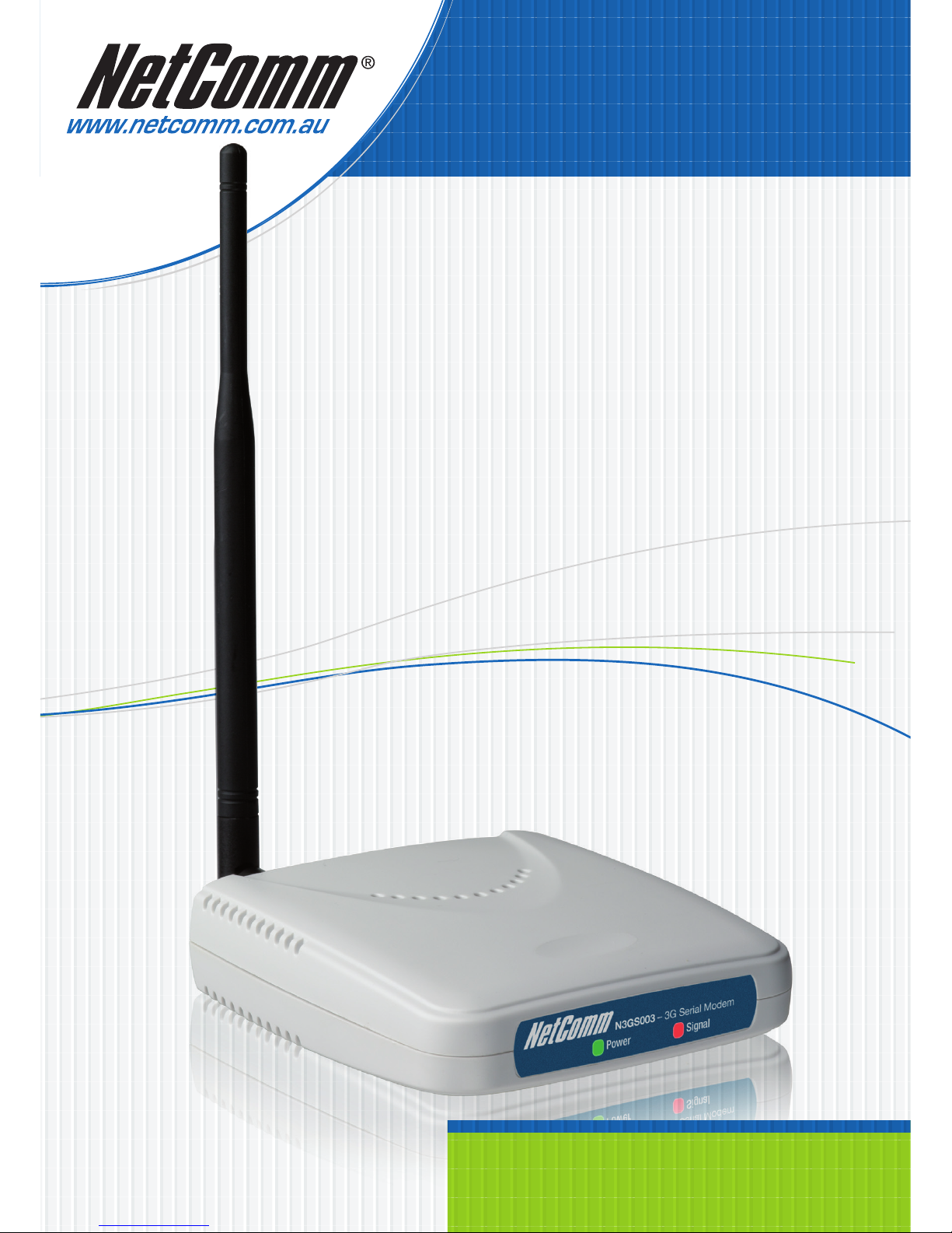
N3GS003
3G Serial Modem
Page 2

N3GS003 3G Serial Modem YML886 draft 0.2
2 www.netcomm.com.au
Contents
1. Introduction ............................................................................................................................................3
1.1 Features ............................................................................................................................................3
1.2 Package Contents ..............................................................................................................................3
1.3 Inserting the SIM card ........................................................................................................................4
1.4 Connecting the cables ........................................................................................................................4
1.5 Getting to know your N3GS003 - LED Indicators ..................................................................................5
2. Driver installation ...................................................................................................................................6
2.1 Windows Vista ...................................................................................................................................6
2.2 Driver removal process .....................................................................................................................10
3. Creating a Dial Up Connection .............................................................................................................11
4. How to dial the connection ..................................................................................................................13
5. Modem Basics ......................................................................................................................................14
5.1 Establishing a Communication Session ..............................................................................................14
5.2 Standard Modem Commands (V.250) ................................................................................................15
5.3 Status Register ................................................................................................................................16
5.4 Result Codes ...................................................................................................................................16
5.5 Jumper ...........................................................................................................................................17
Appendix A – Legal and Regualtory information ........................................................................................18
Important Notice and Safety Precaution
1. Do not operate the device near flammable gassed or fumes. Turn off the device when you are near
a petrol station, fuel depots and chemical plants/depots. Operation of such equipment in potentially
explosive atmospheres can represent a safety hazard.
2. The device and antenna shall be use only with a minimum of 20 cm from human body.
3. The operation of this device may affect medical electronic devices, such as hearing aids and peacemakers.
Page 3
YML886 draft 0.2 N3GS003 3G Serial ModemN3GS003 3G Serial Modem
www.netcomm.com.au 3
CHAPTER 1 INTRODUCTION
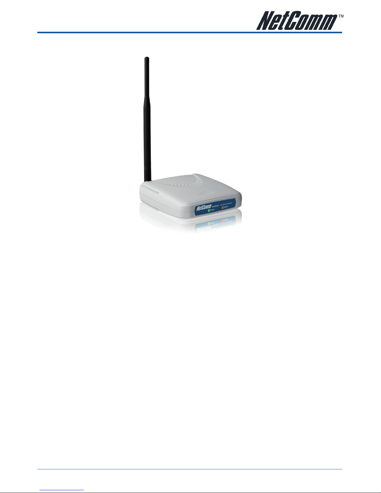
Thank you for purchasing the NetComm N3GS003 3G Serial modem. This User Guide will help you with the
configuration and set-up of your Modem and includes information that will allow you to get a better understand
the advanced features and operation of your new investment.
1.1 Features
• Tri-band UMTS (HSDPA): 850, 1900 and 2100 MHz
• Quad-band EDGE/GPRS/GSM: 850/900/1800/1900 MHz
• Supports third generation (3G) digital cellular standards
• RS 232 serial connection
• AT Command interface
1.2 Package Contents
Your NetComm N3GS003 package contains the following items:
• N3G003S 3G Dial Up modem
• 12V DC 1Amp Power Pack
• Driver / Manual CD
• 850MHz/2100MHz wireless Antenna
If any of the above items are missing or damaged, please contact NetComm immediately.
Page 4
N3GS003 3G Serial Modem YML886 draft 0.2
4 www.netcomm.com.au
1.3 Inserting the SIM card
Please ensure that the modem is not connected to the power cable before proceeding.
• Push the yellow little button besides the SIM card holder.
• Insert the SIM card to the holder with the conductor facing up.
• Insert the SIM card holder with the conductor facing down.
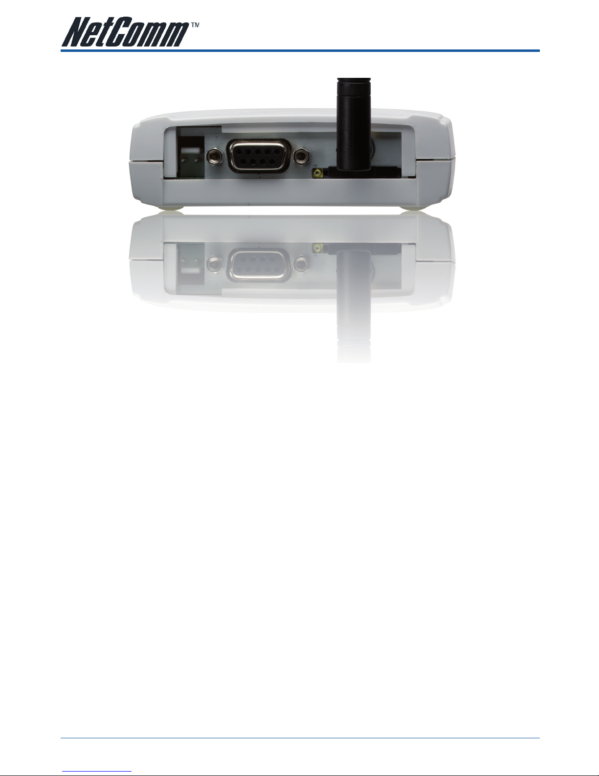
1.4 Connecting the cables
Turn your computer off
• Connect the included antenna to the back of the modem
• Plug the data cable’s (Serial Cable) male end (pins showing) into the socket at the back of your Modem
and then plug the female end (no pins showing) of the same cable into the COM port at the back of your
computer.
• Plug the power cable pin into the POWER socket at the back of your Modem and plug the power supply
into a suitable power point.
Page 5
YML886 draft 0.2 N3GS003 3G Serial ModemN3GS003 3G Serial Modem
www.netcomm.com.au 5
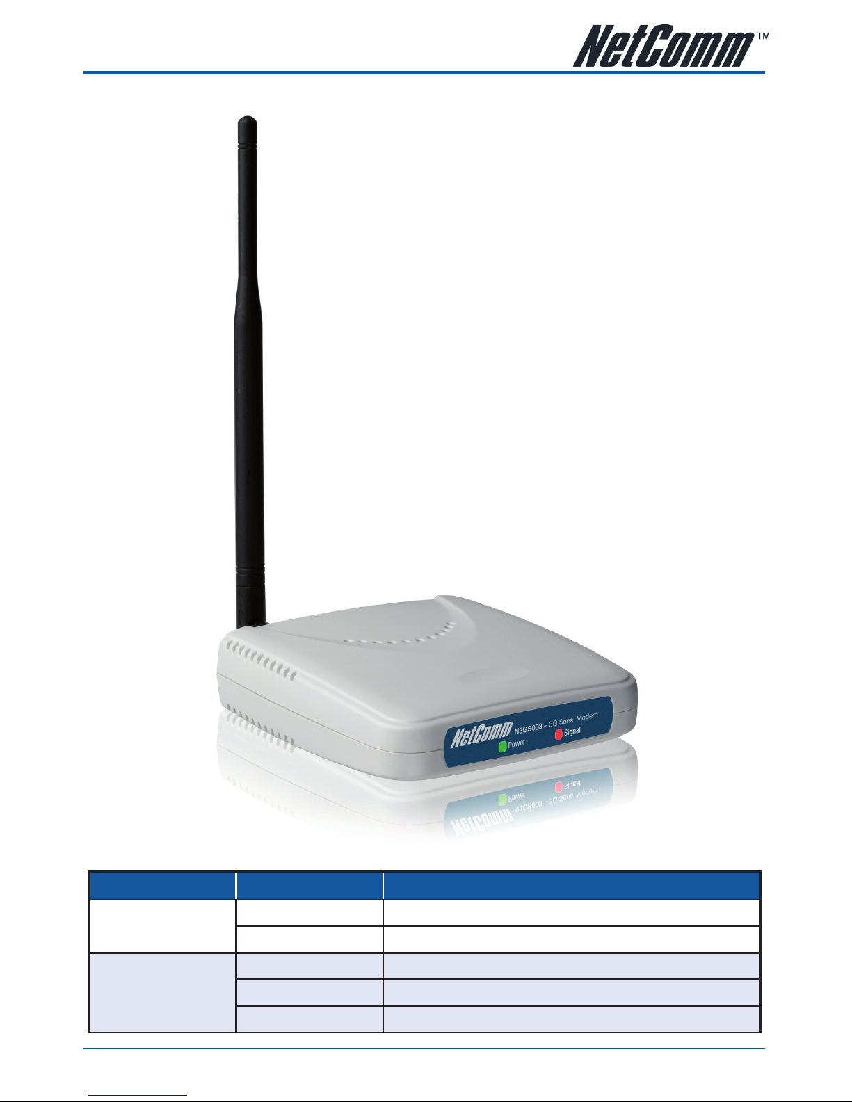
1.5 Getting to know your N3GS003 - LED indicators
Function Color Definition
Power
Off Power is Off
Green Power is on and the device operates normally.
Signal
Slow Blink Unit is searching for a carrier.
Flashing Blink Unit is connected to the network and transmitting or receiving data.
Solid Red Unit is Connected to network but not transmitting or receiving data
Page 6
N3GS003 3G Serial Modem YML886 draft 0.2
6 www.netcomm.com.au
CHAPTER 2 DRIVER INSTALLATION
2.1 Windows Vista
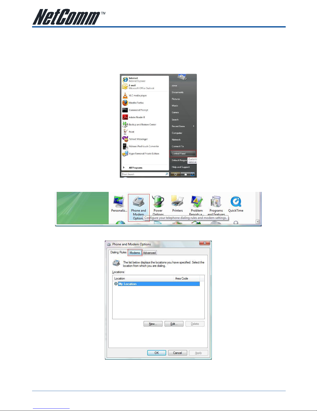
1. Open Control panel window using the Start Menu.
2. On the Control Panel window, click on the Phone and Modem Options to open the Phone and Modem window.
3. On The Phone and Modem Options window, click on the Modem tab.
Page 7
YML886 draft 0.2 N3GS003 3G Serial ModemN3GS003 3G Serial Modem
www.netcomm.com.au 7
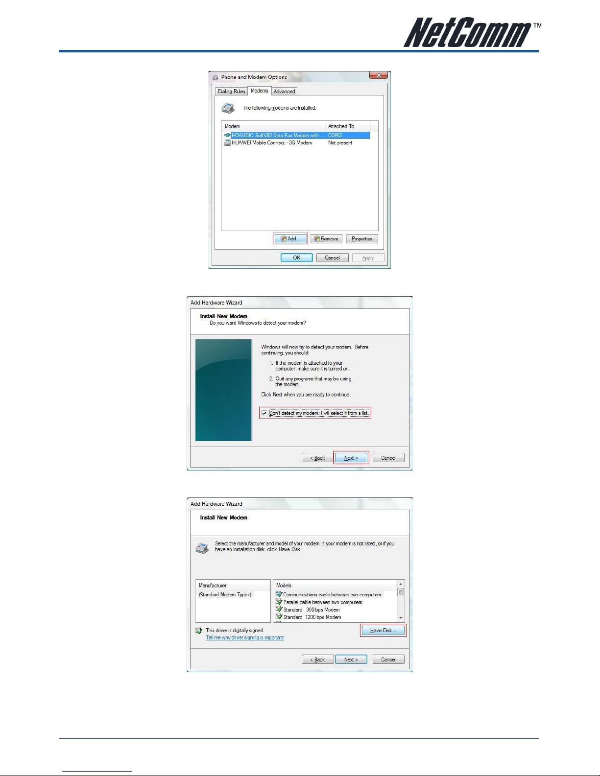
4. Click on the Add Button
5. Tick on “Don’t detect my modem, I will select it from a list” and click on Next
6. Click on Have Disk to select the driver
Page 8
N3GS003 3G Serial Modem YML886 draft 0.2
8 www.netcomm.com.au
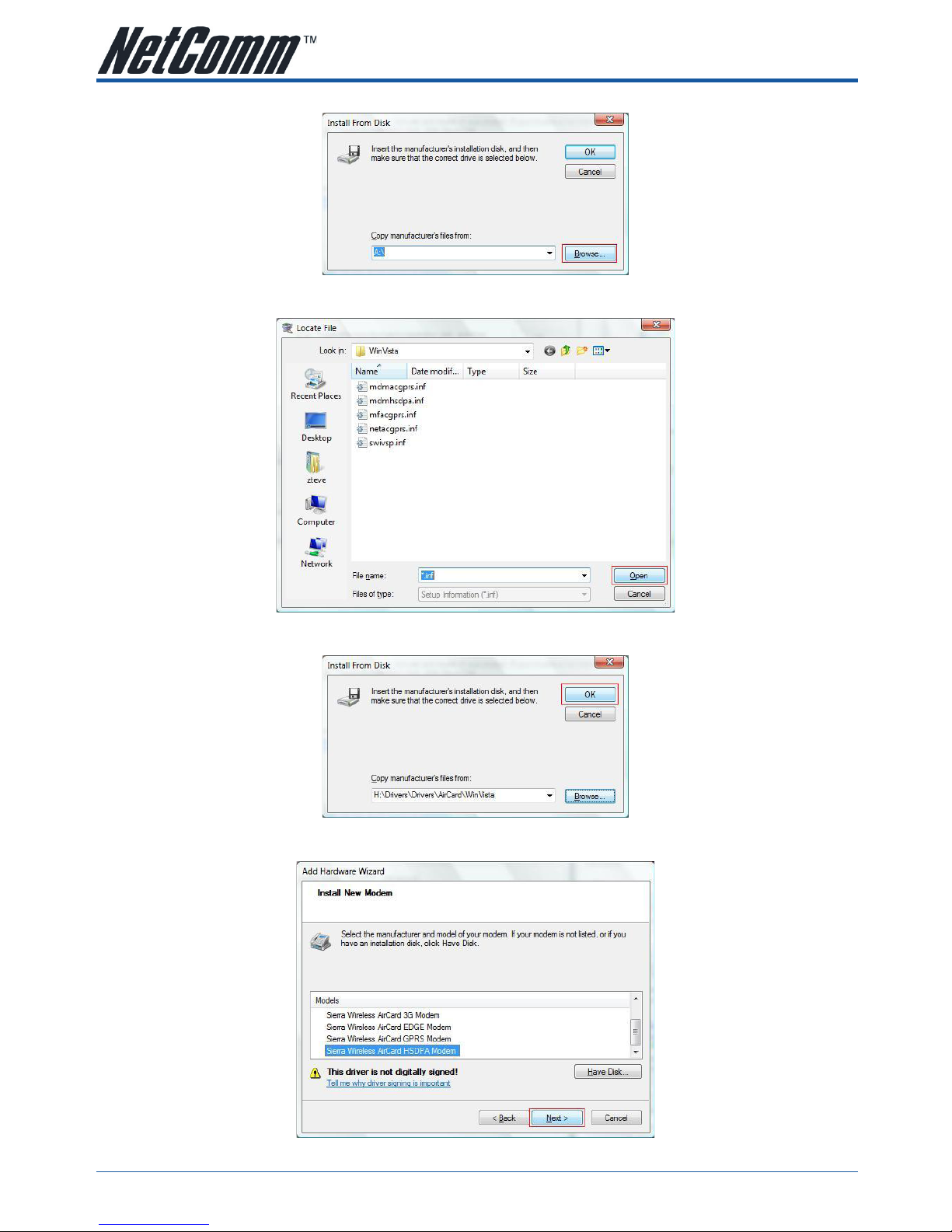
7. Click Browse to select the location of the drivers file.
8. Navigate to the folder that contain the driver files for your Operating System and click on OK
9. Click on OK again
10. Choose “Sierra Wireless AirCard HSDPA Modem” and click on Next
Page 9

YML886 draft 0.2 N3GS003 3G Serial ModemN3GS003 3G Serial Modem
www.netcomm.com.au 9
11. Choose the correct COM port and click on Next
12. Click Finish to finish the installation
Note: This example shows Windows Vista installation, other Windows OS will have a very similar set up process.
Page 10

N3GS003 3G Serial Modem YML886 draft 0.2
10 www.netcomm.com.au
2.2 Driver removal process
1. Open Phone and Modem Options in Control Panel
2. Click on Modems tab
3. Click on “Sierra Wireless AirCard HSDPA Modem” and click on Remove
4. Click OK
Note: This example shows Windows Vista un-installation, other Windows OS will have a very similar set up process.
Page 11
YML886 draft 0.2 N3GS003 3G Serial ModemN3GS003 3G Serial Modem
www.netcomm.com.au 11
CHAPTER 3 CREATING A DIAL UP CONNECTION
1. Open Network and Sharing center from Control Panel window.
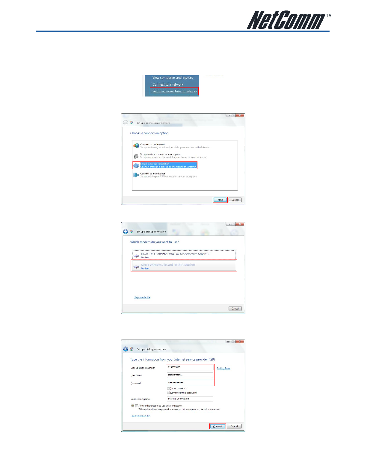
2. Click on the Set up a connection or network on the left menu
3. Click on Set up a dial-up connection and press Next.
4. If you have multiple modems installed on your computer, choose Sierra Wireless AirCard HSDPA Modem.
5. Type in the ISP Dial-Up phone number, the User name and Password. And then click on Connect.
Note: This information should be given to you by your Internet Service Provider.
Page 12

N3GS003 3G Serial Modem YML886 draft 0.2
12 www.netcomm.com.au
6. The computer will try to connect to the internet. Please wait or click on Skip to not connect to the
internet now.
7. If you press Skip on the previous window, click on Set up the connection anyway to save the settings.
8. Click Close to finish the set up.
Page 13

YML886 draft 0.2 N3GS003 3G Serial ModemN3GS003 3G Serial Modem
www.netcomm.com.au 13
CHAPTER 4 HOW TO DIAL THE CONNECTION
1. Open Network and Sharing center from Control Panel window.
2. Click on the Manage network connections on the left menu
3. Double click on the Dial up Connection and click on Dial.
Page 14

N3GS003 3G Serial Modem YML886 draft 0.2
14 www.netcomm.com.au
CHAPTER 5 MODEM BASICS
5.1 Establishing a communication Session
Any Terminal emulation software such as Hyper Terminal can be used to create a communication to the
modem that allows you to issue AT command.
To establish a Hyper Terminal session:
1. Connect the modem to your computer. Refer to Connecting the cables section for more details.
2. Launch HyperTerminal (Start -> Programs -> Accessories -> Communications -> HyperTerminal).
3. Enter the connection name and click OK.
4. Select the communication port that you are using to connect the modem from the Connect using drop
down menu (should be COM1 or COM2 on most computers) and click OK.
5. Change Bits per second to 115200 and click on OK.
The modem supports the following AT command:
- Standard modem commands (ITU-T Recommendation V.250)
- GSM circuit-switched data (3GPP TS 27.005). Please consult the 3GPP website for more details,
www.3gpp.org)
- SMS commands (3GPP TS 27.005). Please consult the 3GPP website for more details, www.3gpp.org)
Note: Some standard commands are not supported or are partially supported.
Calling out using terminal software emulation
After establishing the connection to the modem using terminal emulation software, user can dial out using a
simple ATDT command.
For example: type in “ATDT0294242000”
The modem will then dial out the number (0294242000) and will try to create a connection.
Changing the local data rate
Changing the local data rate can be done using the command AT+IPR=. However, this command will only
store the setting until the modem is reset. Using AT$QCTER= command will save the local data rate setting on
the NV memory and will make it more permanent.
Default value for local data rate is 115200. Acceptable values are: 300, 600, 1200, 2400, 4800, 9600,
19200, 38400, 57600, 115200, and 230400.
Enter PIN Code
If the PIN security is enabled in your SIM card, you need to enter the PIN code before you can use it. To enter
the PIN code, use the AT+CPIN= command.
For example: if your PIN code is 9424, type in “AT+CPIN=9424”.
Page 15

YML886 draft 0.2 N3GS003 3G Serial ModemN3GS003 3G Serial Modem
www.netcomm.com.au 15
5.2 Standard Modem Commands (V.250)
The V.250 is a standardized AT command by the International Telecommunications Union (ITU) as ITU-T
recommendation V.250 (also known as V.25ter). You can find more information on the standard at www.itu.int.
These commands are used to Control serial communications over an asynchronous interface.
The following list shows which command are supported by the modem.
Command Description
&V
Display current modem configuration
+DR
V.42bis compression reporting
+GCAP
Request complete TA capabilities list
+GMI
Modem manufacturer
+GMM
Modem model
+GMR
Current modem firmware version
+GSN
Display IMEI
+ICF
Local character framing
+IFC
Local flow control
+IPR
Fixed local data rate
A/
Reissue last AT command
A
Answer incoming call
D
Dial outgoing call
E<n>
Command echo mode
H[0]
Hang up (disconnect)
I<n>
Display product identification
S0=<n>=<x>
S<n>?
Status Register Set/Query. Refer to Status Register section for more information.
T (ignored)
Tone dialing
V<n>
Verbose result code format
X<n>
Connection code format and call monitoring
Z
Reset modem to user defined profile
Page 16

N3GS003 3G Serial Modem YML886 draft 0.2
16 www.netcomm.com.au
5.3 Status Register
The following table lists all Status Register and their default value.
Reg Description Range Default Units
0
Set the number of rings before answer
Value of 0 disable auto-answering
0-255 000 rings
3
Set command line termination character 0-127 013 (CR) ASCII
4
Set response formatting character 0-127 010 (LF) ASCII
5
Set command line editing character 0-127 008 (BS) ASCII
6
Set length of pause time before dialing 0-255 002 seconds
7
Set wait time for connection 1-255 050 seconds
8
Set length of comma pause 0-255 002 seconds
10
Set carrier detection and carrier loss delay 1-255 014 0.1s
5.4 Result Codes
The modem returns result codes when AT commands are entered. The following table lists the standard
result codes.
Code Verbose Meaning
0
OK Command executed without errors
1
CONNECT Connected at any of the supported speeds
2
RING Alerting Signal (Ring) signal received from the network
3
NO CARRIER Carrier signal lost or not detected. Unable to activate the service
4
ERROR Command not recognized or could not be executed. Illegal command. Error in
command line. Command line exceeds buffer size. Parameters out of range.
6
NO DIAL TONE Dial tone not detected within timeout and subsequent commands not processed
7
BUSY Reorder (Busy) signal detected and subsequent commands not processed.
8
NO ANSWER Five seconds of silence not detected after ring back when “@” (quite answer) dial
modifier is used.
Page 17

YML886 draft 0.2 N3GS003 3G Serial ModemN3GS003 3G Serial Modem
www.netcomm.com.au 17
5.5 Jumper
The N3GS003 modem has internal jumpers to control the behavior of the modem in relation with DTR/
DSR/DCD signals from the computer. For most application, these jumpers can be leave as default.
1
3
2JP 1
JP 2
JP 3
4
6
5
7
9
8
These jumpers control some of the RS232 serial port signals, and have the following functions:
Jumper 1:
• Position 1 - DTR - Jumper in this position passes the DTR signal to modem controller (not currently
implemented).
• Position 2 - DTR - Jumper in this position the DTR signal is not passed to the modem controller (default).
• Position 3 - DTR - Jumper in this position the DTR signal is not passed to the modem controller.
Jumper 2:
• Position 4 - DSR - With a jumper in this position the DSR signal is controlled by the modem
controller (not currently implemented).
• Position 5 - DSR - With a jumper in this position the DSR signal is controlled by the DTR signal (default).
• Position 6 - DSR - With a jumper in this position the DSR signal is on always.
Jumper 3:
• Position 7 - DCD - With a jumper in this position the DCD signal is controlled by the modem
controller (not currently implemented).
• Position 8 - DCD - With a jumper in this position the DCD signal is controlled by the DTR signal (default).
• Position 9 - DCD - With a jumper in this position the DCD signal is on always.
Page 18

N3GS003 3G Serial Modem YML886 draft 0.2
18 www.netcomm.com.au
APPENDIX A LEGAL & REGULATORY INFORMATION
This manual is copyright. Apart from any fair dealing for the purposes of private study, research, criticism or review, as permitted under the
Copyright Act, no part may be reproduced, stored in a retrieval system or transmitted in any form, by any means, be it electronic, mechanical,
recording or otherwise, without the prior written permission of NetComm Limited. NetComm Limited accepts no liability or responsibility, for
consequences arising from the use of this product.
NetComm Limited reserves the right to change the specifications and operating details of this product without notice.
NetComm is a registered trademark of NetComm Limited.
All other trademarks are acknowledged the property of their respective owners.
Customer Information
ACA (Australian Communications Authority) requires you to be aware of the following information and warnings:
(1) This unit shall be connected to the Telecommunication Network through a line cord which meets the requirements of the ACA TS008
Standard.
(2) This equipment has been tested and found to comply with the Standards for C-Tick and or A-Tick as set by the ACA . These standards are
designed to provide reasonable protection against harmful interference in a residential installation. This equipment generates, uses, and can
radiate radio noise and, if not installed and used in accordance with the instructions detailed within this manual, may cause interference to
radio communications. However, there is no guarantee that interference will not occur with the installation of this product in your home or
office. If this equipment does cause some degree of interference to radio or television reception, which can be determined by turning the
equipment off and on, we encourage the user to try to correct the interference by one or more of the following measures:
• Change the direction or relocate the receiving antenna.
• Increase the separation between this equipment and the receiver.
• Connect the equipment to an alternate power outlet on a different power circuit from that to which the receiver/TV is connected.
• Consult an experienced radio/TV technician for help.
(3) The power supply that is provided with this unit is only intended for use with this product. Do not use this power supply with any other
product or do not use any other power supply that is not approved for use with this product by NetComm. Failure to do so may cause damage
to this product, fire or result in personal injury.
Page 19

YML886 draft 0.2 N3GS003 3G Serial ModemN3GS003 3G Serial Modem
www.netcomm.com.au 19
Product Warranty
The warranty is granted on the following conditions:
1. This warranty extends to the original purchaser (you) and is not transferable;
2. This warranty shall not apply to software programs, batteries, power supplies, cables or other accessories supplied in or with the product;
3. The customer complies with all of the terms of any relevant agreement with NetComm and any other reasonable requirements of NetComm
including producing such evidence of purchase as NetComm may require;
4. The cost of transporting product to and from NetComm’s nominated premises is your responsibility; and,
5. NetComm does not have any liability or responsibility under this warranty where any cost, loss, injury or damage of any kind, whether direct,
indirect, consequential, incidental or otherwise arises out of events beyond NetComm’s reasonable control. This includes but is not limited to:
acts of God, war, riot, embargoes, acts of civil or military authorities, fire, floods, electricity outages, lightning, power surges, or shortages of
materials or labour.
6. The customer is responsible for the security of their computer and network at all times. Security features may be disabled within the factory
default settings. NetComm recommends that you enable these features to enhance your security.
The warranty is automatically voided if:
1. You, or someone else, use the product, or attempts to use it, other than as specified by NetComm;
2. The fault or defect in your product is the result of a voltage surge subjected to the product either by the way of power supply or
communication line, whether caused by thunderstorm activity or any other cause(s);
3. The fault is the result of accidental damage or damage in transit, including but not limited to liquid spillage;
4. Your product has been used for any purposes other than that for which it is sold, or in any way other than in strict accordance with the user
manual supplied;
5. Your product has been repaired or modified or attempted to be repaired or modified, other than by a qualified person at a service centre
authorised by NetComm; and,
6. The serial number has been defaced or altered in any way or if the serial number plate has been removed.
Limitations of Warranty
The Trade Practices Act 1974 and corresponding State and Territory Fair Trading Acts or legalisation of another Government (“the relevant acts”) in
certain circumstances imply mandatory conditions and warranties which cannot be excluded. This warranty is in addition to and not in replacement
for such conditions and warranties.
To the extent permitted by the Relevant Acts, in relation to your product and any other materials provided with the product (“the Goods”) the liability
of NetComm under the Relevant Acts is limited at the option of NetComm to:
• Replacement of the Goods; or
• Repair of the Goods; or
• Payment of the cost of replacing the Goods; or
• Payment of the cost of having the Goods repaired.
All NetComm ACN 002 490 486 products have a standard 12 months warranty from date of purchase. However some products have an
extended warranty option (refer to packaging). To be eligible for the extended warranty you must supply the requested warranty information
to NetComm within 30 days of the original purchase by registering on-line via the NetComm web site at
www.netcomm.com.au
Page 20

Contact Information
If you have any technical difficulties with your product, please do not hesitate to contact NetComm’s Customer Support Department.
Email: support@netcomm.com.au
www.netcomm.com.au
Note: NetComm Technical Support for this product only covers the basic installation and features. For further information regarding the advanced features of this
product, please refer to the configuring sections in this User Guide or contact a Network Specialist.
NetComm Limited ABN 85 002 490 486
PO Box 1200, Lane Cove NSW 2066 Australia
E – sales@netcomm.com.au W – www.netcomm.com.au
 Loading...