

Page 1
Vodafone MachineLink 3G
USER GUIDE
Page 2
2
Vodafone MachineLink 3G
www.netcommwireless.com and m2m.vodafone.com
Copyright
Copyright© 2013 NetComm Wireless Limited. All rights reserved.
Copyright© 2013 Vodafone Group Plc. All rights reserved.
The information contained herein is proprietary to NetComm Wireless and Vodafone. No part of this document may be translated, transcribed,
reproduced, in any form, or by any means without prior written consent of NetComm Wireless and Vodafone.
Please note: This document is subject to change without notice.
Save our environment
When this equipment has reached the end of its useful life, it must be taken to a recycling centre and processed separately from domestic waste.
The cardboard box, the plastic contained in the packaging, and the parts that make up this device can be recycled in accordance with regionally
established regulations. Never dispose of this electronic equipment along with your household waste. You may be subject to penalties or
sanctions under the law. Instead, ask for disposal instructions from your municipal government.
Please be responsible and protect our environment.
This user guide covers the following products:
Vodafone MachineLink 3G M2M Router
DOCUMENT VERSION DATE
Initial document release 9 April 2013
Cosmetic fixes 17 May 2013
Aligned to firmware version 1.10.16.X. Added description of Data usage button and Ethernet port LED
indicators
12 June 2013
Aligned to firmware version 1.10.32.X. Added Vodafone GDSP roaming settings page, hostname
description on LAN settings page and updated Administration settings screenshot and descriptions.
20 September 2013
Table 1 - Document Rev ision History
Page 3

www.netcommwireless.com and m2m.vodafone.com
Vodafone MachineLink 3G
3
Table of contents
Overview ......................................................................................................................................................................................................................................................................................... 4
Introduction ............................................................................................................................................................................................................................................................................................... 4
Target audience ....................................................................................................................................................................................................................................................................................... 4
Prerequisites .............................................................................................................................................................................................................................................................................................. 4
Notation ...................................................................................................................................................................................................................................................................................................... 4
Product introduction ................................................................................................................................................................................................................................................................. 5
Product overview ..................................................................................................................................................................................................................................................................................... 5
Package contents .................................................................................................................................................................................................................................................................................... 5
Product features....................................................................................................................................................................................................................................................................................... 6
Physical dimensions and indicators.................................................................................................................................................................................................................................... 7
Physical dimensions ............................................................................................................................................................................................................................................................................... 7
LED indicators ........................................................................................................................................................................................................................................................................................... 8
Ethernet port LED indicators................................................................................................................................................................................................................................................................ 9
Interfaces ................................................................................................................................................................................................................................................................................................. 10
Placement of the MachineLink 3G router ..................................................................................................................................................................................................................... 11
Mounting options ................................................................................................................................................................................................................................................................................. 11
Installation and configuration of the Vodafone MachineLink 3G ....................................................................................................................................................................... 16
Powering the router ............................................................................................................................................................................................................................................................................. 16
Power consumption ............................................................................................................................................................................................................................................................................. 17
Installing the router ............................................................................................................................................................................................................................................................................. 17
Advanced configuration ....................................................................................................................................................................................................................................................... 18
Status ............................................................................................................................................................................................................................................................................................ 19
Networking ................................................................................................................................................................................................................................................................................. 21
Data connection .................................................................................................................................................................................................................................................................................... 21
Connect on demand ............................................................................................................................................................................................................................................................................ 29
Operator settings .................................................................................................................................................................................................................................................................................. 32
SIM security settings............................................................................................................................................................................................................................................................................ 34
LAN ............................................................................................................................................................................................................................................................................................................ 38
Routing ..................................................................................................................................................................................................................................................................................................... 42
VPN ............................................................................................................................................................................................................................................................................................................ 52
Services ........................................................................................................................................................................................................................................................................................ 65
Dynamic DNS ......................................................................................................................................................................................................................................................................................... 65
Network time (NTP).............................................................................................................................................................................................................................................................................. 66
Ping watchdog ....................................................................................................................................................................................................................................................................................... 67
SNMP ......................................................................................................................................................................................................................................................................................................... 69
TR-069 ...................................................................................................................................................................................................................................................................................................... 71
SMS Diagnostics and Commands.................................................................................................................................................................................................................................................... 72
Diagnostics .............................................................................................................................................................................................................................................................................................. 76
Sending an SMS diagnostic command .......................................................................................................................................................................................................................................... 79
System.......................................................................................................................................................................................................................................................................................... 86
Log ............................................................................................................................................................................................................................................................................................................. 86
System configuration .......................................................................................................................................................................................................................................................................... 89
Appendix A: Tables .................................................................................................................................................................................................................................................................. 97
Appendix B: Device Mounting Dimensions ................................................................................................................................................................................................................... 98
Appendix C: Mounting Bracket ........................................................................................................................................................................................................................................... 99
Appendix D: Default Settings ........................................................................................................................................................................................................................................... 100
Restoring factory default settings ................................................................................................................................................................................................................................................ 101
Recovery mode ................................................................................................................................................................................................................................................................................... 102
Appendix E: HTTP Secure .................................................................................................................................................................................................................................................. 103
What is HTTP Secure? ........................................................................................................................................................................................................................................................................ 103
Generating your own self-signed certificate ............................................................................................................................................................................................................................. 103
Uploading a self-signed certificate ............................................................................................................................................................................................................................................... 105
Appendix F: RJ-45 connector ........................................................................................................................................................................................................................................... 107
Safety and product care ..................................................................................................................................................................................................................................................... 108
Page 4
4
Vodafone MachineLink 3G
www.netcommwireless.com and m2m.vodafone.com
Overview
Introduction
This document provides you all the information you need to set up, configure and use the Vodafone MachineLink 3G Router.
Target audience
This document is intended for system integrators or experienced hardware installers who understand telecommunications terminology and
concepts.
Prerequisites
Before continuing with the installation of your Vodafone MachineLink 3G, please confirm that have the following:
1. A device with a working Ethernet network adapter.
2. A web browser such as Internet Explorer, Mozilla Firefox or Google Chrome.
3. A working SIM card if your router was not shipped with one pre-inserted.
4. A flathead screwdriver (No. 3) if field terminated power is required.
Notation
The following symbols are used in this user guide:
The following note requires attention
The following note provides a warning
The following note provides useful information
Page 5

www.netcommwireless.com and m2m.vodafone.com
Vodafone MachineLink 3G
5
Product introduction
Product overview
HSPA+ up to 14.4Mbps downstream
Penta-band 3G with quad-band 2G auto-fallback
Internal diversity antennae with option for external main antenna (auto-sensing)
Ethernet port with full passive Power over Ethernet (PoE) support (802.3af)
Intelligent tri-colour LED display for clear, easy-to-read modem status information
Integration with Vodafone GDSP back end
Roaming algorithm with prioritisation for cost effective, flawless network connection across the globe
Extensive device management with support for TR-069, web configuration and full feature management with SMS
Optimised web configuration
Flexible mounting suitable for in-home use or industrial applications with built-in wall mount, DIN and C-Rail mounting options
Package contents
The Vodafone MachineLink 3G package consists of:
1x Vodafone MachineLink 3G router
1x 1.5m yellow Ethernet cable 8P8C
1x DIN rail mounting bracket
1x quick start guide and safety manual
If any of these items are missing or damaged, please contact NetComm Wireless Support or your Vodafone sales representative immediately. The
NetComm Wireless Support website can be found at: http://support.netcommwireless.com and the Vodafone support agreement details are part
of your commercial contract with Vodafone.
Page 6

6
Vodafone MachineLink 3G
www.netcommwireless.com and m2m.vodafone.com
Product features
The Vodafone MachineLink 3G is a feature-packed wireless M2M device designed by Vodafone to address the rapid growth in M2M deployments.
The first M2M device of its kind, it is designed to deliver state of the art features, versatility and ease of use at an affordable price. Compatible with
Vodafone networks worldwide, MachineLink is managed by Vodafone's global M2M platform enabling remote management and support wherever
you are. The open management system also allows you to customise your own software applications for scalability, large scale compatibility and
an easy path to large deployments across a broad range of industries.
The Vodafone MachineLink 3G meets the global demand for a reliable and cost-effective M2M device that successfully caters to mass deployment
across businesses.
Page 7
www.netcommwireless.com and m2m.vodafone.com
Vodafone MachineLink 3G
7
Physical dimensions and indicators
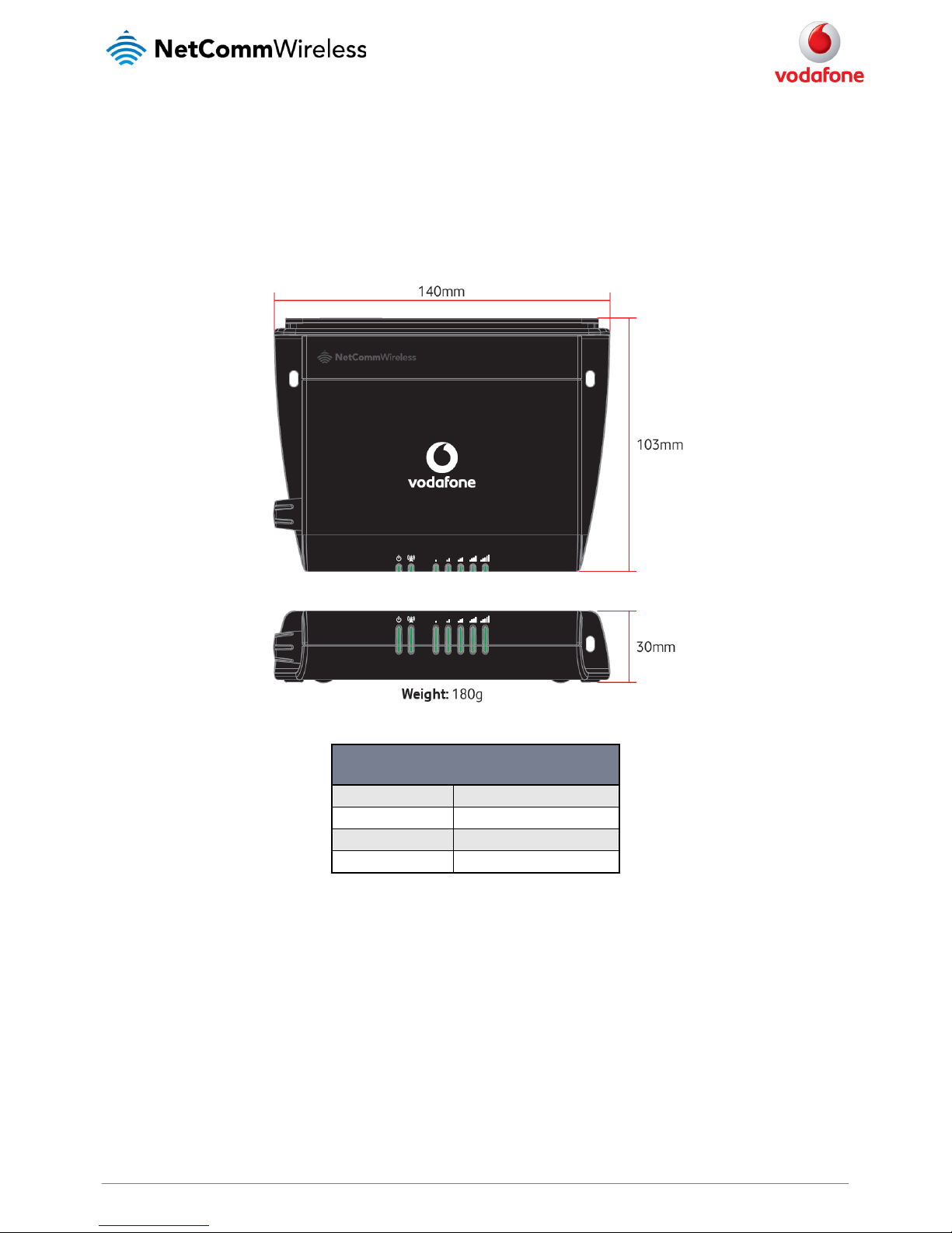
Physical dimensions
Below is a list of the physical dimensions of the Vodafone MachineLink 3G.
Figure 1 – Vodafone MachineLink 3G Dim ensions
VODAFONE MACHINELINK 3G
(WITHOUT EXTERNAL ANTENNA ATTACHED)
Length 140 mm
Depth 103 mm
Height 30 mm
Weight 180g
Table 2 - Device Dimensions
Page 8
8
Vodafone MachineLink 3G
www.netcommwireless.com and m2m.vodafone.com
LED indicators
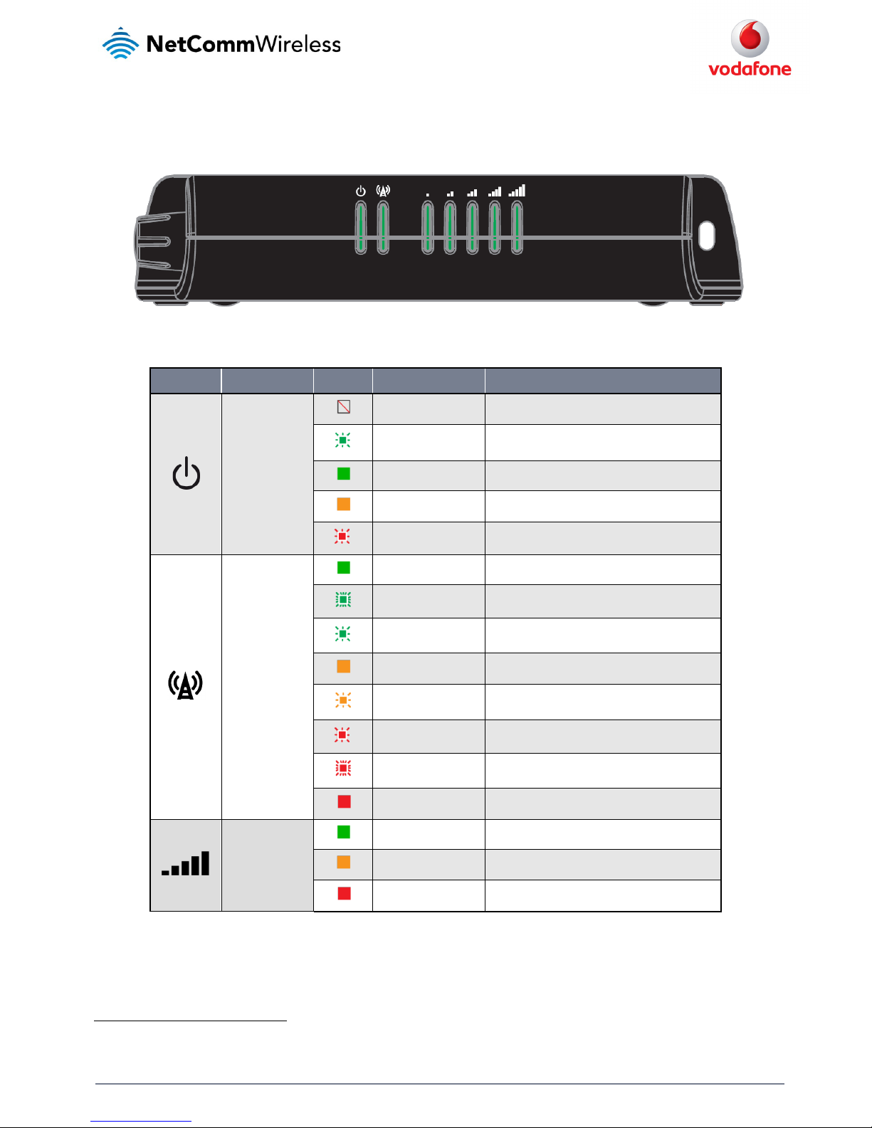
The Vodafone MachineLink 3G uses 7 LEDs to display the current system and connection status.
Figure 2 - Vodafone MachineLink 3G LED Indicators
LED ICON NAME COLOUR STATE DESCRIPTION
Power
Off Power off
Double flash Powering up
On Power on
On Power on in recovery mode
Slow flashing Hardware error
Network
On Connected v ia WWAN
Blinking1
Traffic via WWAN
Slow flashing Connecting PDP
On Registered network
Slow flashing Registering network
Slow flashing SIM PIN locked
Fast flashing SIM PUK lock ed
On Can’t connect
Signal strength
On 3G
On 2G GPRS
On GSM only (n o GPRS)
Table 3 - LED Indicators
1
The term “blinking” means that the LED may pulse, with the intervals that the LED is on and off not being equal. The term “flashing” means that the LED turns on
and off at equal intervals.
Page 9
www.netcommwireless.com and m2m.vodafone.com
Vodafone MachineLink 3G
9
Signal strength LEDs
The following table lists the signal strength range corresponding with the number of lit signal strength LEDs.
NUMBER OF LIT LEDS SIGNAL STRENGTH
All LEDs unlit
< -109 dBm
1
-109 dBm < -101dBm
2 -101 dBm < -91 dBm
3 -91 dBm < -85 dBm
4 -85 dBm < -77 dBm
5
≥ -77 dBm
Table 4 - Signal strength LED descriptions
LED update interval
The signal strength LEDs update within a few seconds with a rolling average signal strength reading. When selecting a location for the router or
connecting or positioning an external antenna, please allow up to 20 seconds for the signal strength LEDs to update before repositioning.
Ethernet port LED indicators
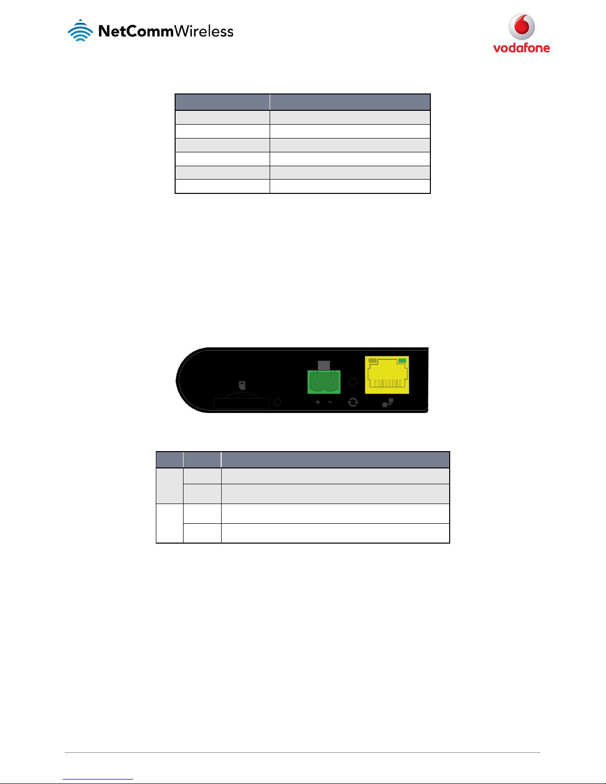
The Ethernet port of the Vodafone MachineLink 3G router has two LED indicators on it.
Figure 3 - Ethernet port LED indicato rs
The table below describes the statuses of each light and their meanings.
LED STATUS DESCRIPTION
Green
On There is a valid network link.
Blinking There is activity on the net work link.
Amber
On The Ethernet port is operating a t a speed of 100Mbps.
Off The Ethernet port is operating at a speed of 10Mbps or no Ethernet cable is connected.
Table 5 - Ethernet port L ED indicators description
Page 10
10
Vodafone MachineLink 3G
www.netcommwireless.com and m2m.vodafone.com
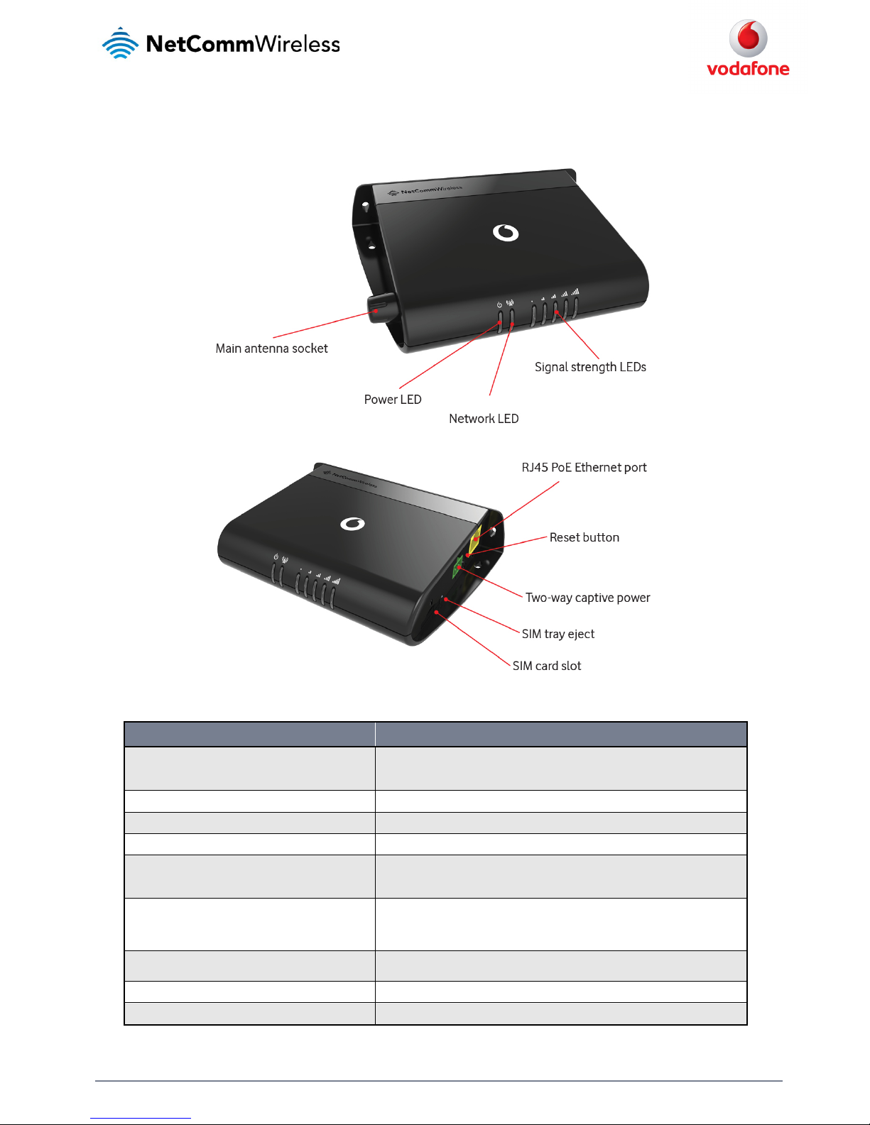
Interfaces
The following interfaces are available on the Vodafone MachineLink 3G:
Figure 4 - Interfaces
ITEM DESCRIPTION
External main antenna socket
SMA female connector for an o ptional external antenna (not supplied). The main internal antenna
is disabled when an external ant enna is connected but the auxiliary antenna remains active to
provide (where possible) diversity assistance.
Power LED Indicates the power status of th e device and whether the device is in recovery mode.
Network LED Indicates the network and SIM s tatus.
Signal strength LEDs Indicates the signal strength and network type.
RJ45 PoE Ethernet port
Connect one or several devices via a network switch here. This port can also o ptionally receive
Power over Ethernet (802.3 af PoE) in which case the DC power supply can serve as b ackup power
source if required.
Reset button
Press and hold for less than 5 s econds to reboot to normal mode.
Press and hold for 5 to 15 secon ds to reboot to recovery mode.
Press and hold for 15 to 20 seco nds to reset the router to factory default settin gs.
Two-way captive power
Connect power source here. Power wires may be terminated on optional termina l block and
connected to DC input jack. Operates in the 8-35V DC range.
SIM tray eject Insert a pencil or pape r clip here to eject the SIM card tray.
SIM card slot Insert SIM card here.
Table 6 - Interfaces
Page 11

www.netcommwireless.com and m2m.vodafone.com
Vodafone MachineLink 3G
11
Placement of the MachineLink 3G
router
When selecting a location to mount the MachineLink 3G router, keep in mind that it houses two high performance internal antennas designed to
provide optimum signal strength in a wide range of environments. If you find the signal strength is weak, try moving the router to a different place
or mounting it differently. If signal strength doesn’t improve, you may need to attach an external antenna (not included) to the router’s female
SMA connector.
Note: If you connect an external antenna to the female SMA connector, the main internal antenna disables automatically but the
auxiliary internal antenna remains connected to provide (where possible) diversity assistance.
Note: When selecting a location for the router, allow at least 20 seconds for the signal strength LEDs to update before trying a different
location or connecting an external antenna.
Mounting options
The Vodafone MachineLink 3G router can be quickly and easily mounted in a variety of locations.
Mounted flat against the wall
When mounted flat against the wall, the MachineLink 3G router has a slimline form factor. Use appropriately sized screws in the mounting holes
provided on the base of the unit.
Figure 5 - Wall mount - Flat against th e wall
Perpendicular to the wall
If a large surface area is not available, there is the option of mounting the router perpendicular to the wall. This gives the router a small wall
footprint while remaining securely attached. Use appropriately sized screws in the mounting holes provided on the back of the unit.
Page 12
12
Vodafone MachineLink 3G
www.netcommwireless.com and m2m.vodafone.com
Figure 6 - Wall mount - Perpendicular to the wall
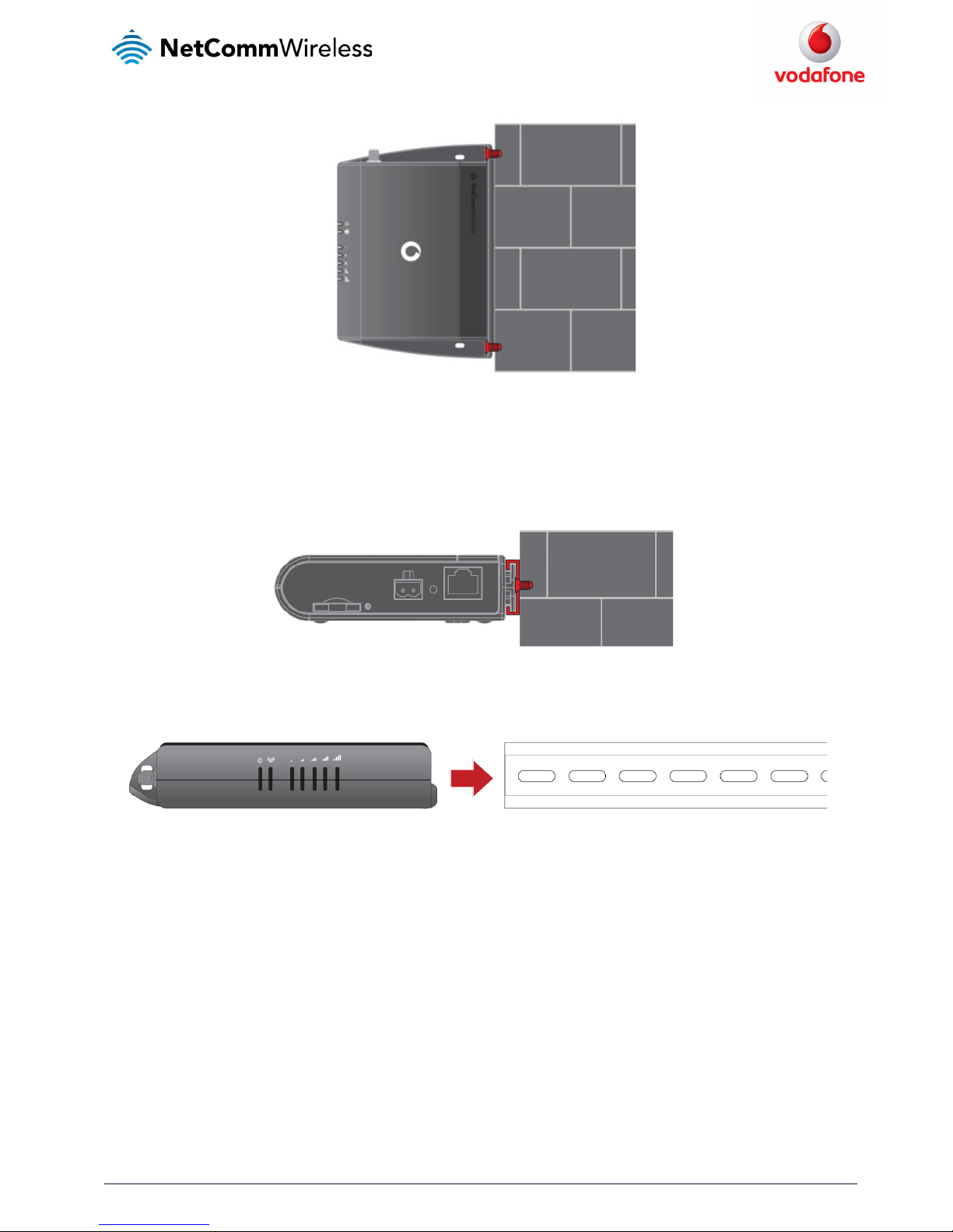
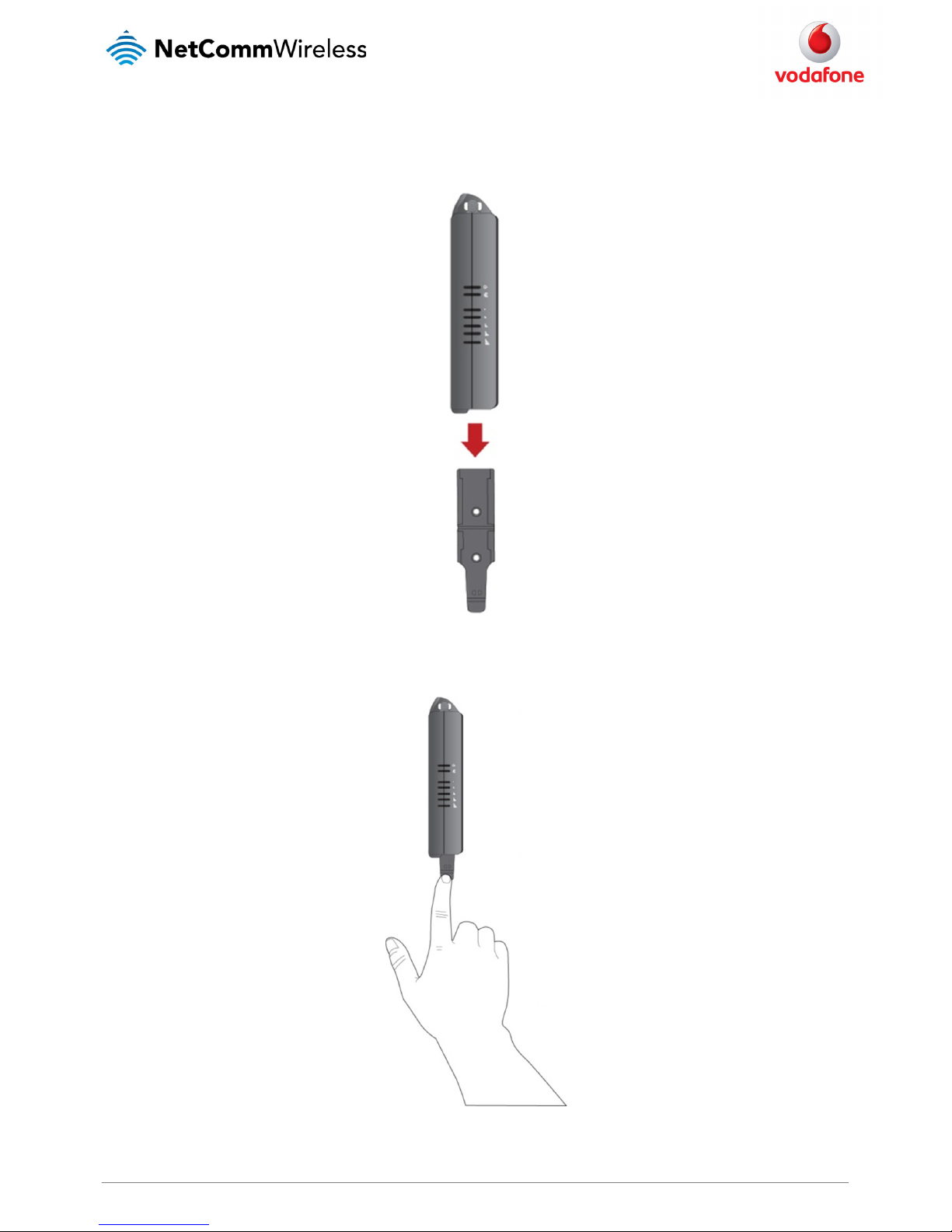
C Section DIN Rail mount
The MachineLink 3G router easily slides onto a C Section DIN rail so that it is horizontally mounted. The DIN Rail mounting bracket is not required
for C Section DIN rail mounting.
Figure 7 - C Section DIN rail mount
To mount the unit on a C-Section DIN rail, slide it on as illustrated below:
Figure 8 - Mounting the unit on a DI N rail
Page 13
www.netcommwireless.com and m2m.vodafone.com
Vodafone MachineLink 3G
13
Mounting bracket
The provided mounting bracket provides additional methods of mounting the MachineLink 3G Router.
To attach the mounting bracket, slide it onto the rear of the router as shown in the diagram below:
Figure 9 - Sliding on the mounting bracket
To remove the bracket, press the PUSH button and slide the router off the bracket:
Figure 10 - Removing the mounting bracket
Page 14
14
Vodafone MachineLink 3G
www.netcommwireless.com and m2m.vodafone.com
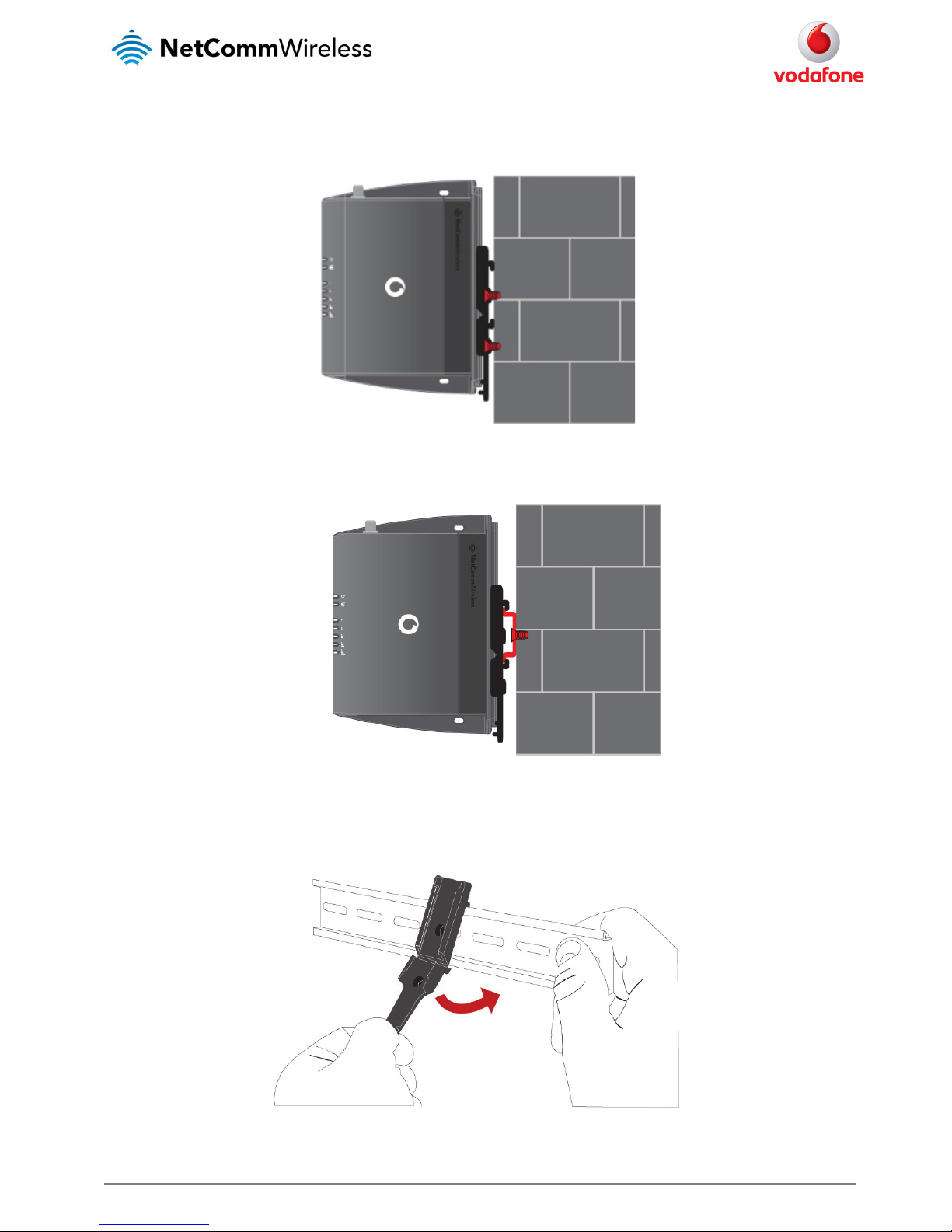
Using the mounting bracket for wall mounting
By first attaching the DIN rail bracket to the wall, the MachineLink 3G can be easily attached and removed from the bracket.
Figure 11 – Wall mount - Mounted via DIN rail bracket
Using the mounting bracket for Top hat DIN rail mounting
The MachineLink 3G Router may be vertically mounted to the wall with the bracket by sliding the bracket onto a top hat DIN rail
Figure 12 - Top hat DIN rail mount
Alternatively, you can attach it to the DIN Rail by using the V bend in the bracket as illustrated below:
Figure 13 - Attaching the mounting b racket to the DIN rail using the V bend
Page 15

www.netcommwireless.com and m2m.vodafone.com
Vodafone MachineLink 3G
15
Desk mount
In situations where wall mounts and DIN rails are not required, you can simply place the MachineLink 3G router on a desk using its rubber feet to
prevent it from slipping.
Figure 14 - Desk mount
Page 16
16
Vodafone MachineLink 3G
www.netcommwireless.com and m2m.vodafone.com
Installation and configuration of the
Vodafone MachineLink 3G
Powering the router
The MachineLink 3G Router can be powered in one of three ways:
1. Power over Ethernet (802.3af PoE)
2. DC power input via 2-pin connector (8-35V DC)
3. DC power input via field terminated power source (8-35V DC)
4. The green power LED on the router lights up when a power source is connected.
Power over Ethernet (802.3af PoE)
Power over Ethernet (PoE) is a method of connecting network devices through Ethernet cable where power and data are passed along a single
cable. This may be a desirable method of powering the device if PoE is available, or if it’s most convenient in the desired installation environment
to only have a single cable running to the MachineLink 3G device.
There are 5 power classes defined in the IEEE 802.3-2005 standard, of which the Vodafone MachineLink 3G is a class 3 device.
CLASS
CLASSIFICATION
CURRENT
POWER RANGE CLASS DESCRIPTION
3 26-30 mA 6.49 – 12.95 W Mid power
Table 7 - PoE po wer classes
To use PoE to power the MachineLink 3G, simply connect your router to a PoE injector or PoE network switch using the bundled yellow Ethernet
cable 8P8C.
DC power via 2-pin connector
The DC input jack can accept power from a separately sold DC power supply. Both a standard temperature range DC power supply and an extended
temperature range DC power supply are available to purchase as accessories.
To power the device via DC Power via the 2-pin connector, remove the attached green terminal block from your router and connect the external
DC power supply to the router’s green DC power jack.
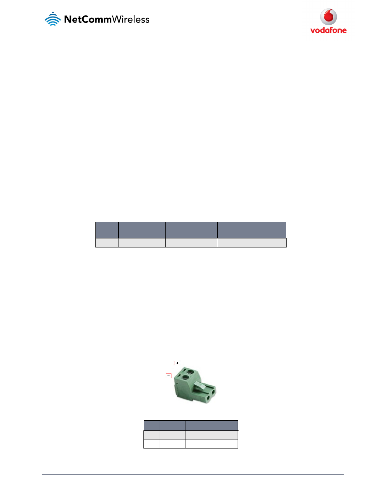
DC power via field terminated power source
If an existing 8-35V DC power supply is available, you can insert the wires into the supplied terminal block to power your router. Use a No. 3
flathead screwdriver to tighten the terminal block screws and secure the power wires, making sure the polarity of the wires are correctly matched,
as illustrated below.
Figure 15 - Locking Power Terminal Block
PIN SIGNAL DESCRIPTION
+ V+ Voltage +
- V- Ground
Table 8 - Locking powe r block pin outs
Page 17
www.netcommwireless.com and m2m.vodafone.com
Vodafone MachineLink 3G
17
Failover power support
The MachineLink 3G Router includes support for connection of two power sources at the same time. When a PoE Ethernet cable is connected and
DC power is also supplied to the DC input jack of the router, the router will source power exclusively from the PoE source. In the event that power
from the PoE cable is lost, the router will automatically switch to source power from the DC input jack, without affecting the router’s operation.
When PoE power is restored, the router automatically switches back to receive power from the PoE input source.
Viewing power source information
You can view the current power input mode in the Advanced status section of the device’s Web user interface. This is useful for remotely
monitoring the device. You can also use the Software Development Kit to access this information for advanced purposes (e.g. configuring SMS
alerts to inform you of the power status of the router).
To view the router’s power source information, log in to the router and expand the Advanced status box on the status page. See the
Status
section of this manual for more information on the status page.
Power consumption
To assist with power consumption planning, the following table summarises average power consumption during the various states of the
MachineLink 3G under normal usage conditions. It’s important to note that this table serves as an indication only as the power consumed by the
device is affected by many variables including signal strength, network type, and network activity.
Average power consumption figures
STATE POWER CONSUMPTION
Powered on, idle and connec ted to packet data 1.2W
Powered on, connected to pack et data with average load 2.0W
Powered on, connected to pack et data with heavy traffic 4.0W
Peak power draw at maximum 3G module transmission power 5.0W
Table 9 - Average power consumption figures
Installing the router
After you have mounted the router and connected a power source, follow these steps to complete the installation process.
1. Connect equipment that requires network access to the Ethernet port of your router. This may be your computer for advanced
configuration purposes, or your end equipment which requires data access via the MachineLink 3G. You can connect one device
directly, or several devices using a network switch.
If you’re using PoE as the power source, you need to connect any devices via an available data Ethernet port on your PoE power source
(be it a PoE network switch or PoE power injector).
2. Ensure the external power source is switched on and wait 2 minutes for your Vodafone MachineLink 3G to start up and connect to the
mobile network. Your router has an active SIM card preinstalled and arrives with preconfigured settings that should suit most customers.
Your router is now connected. To check the status of your router, compare the LED indicators on the device with those listed on page 8
of this guide.
Page 18
18
Vodafone MachineLink 3G
www.netcommwireless.com and m2m.vodafone.com
Advanced configuration
The Vodafone MachineLink 3G Router comes with preconfigured settings that should suit most customers. For advanced configuration, login to
the web-based user interface of the Vodafone MachineLink 3G.
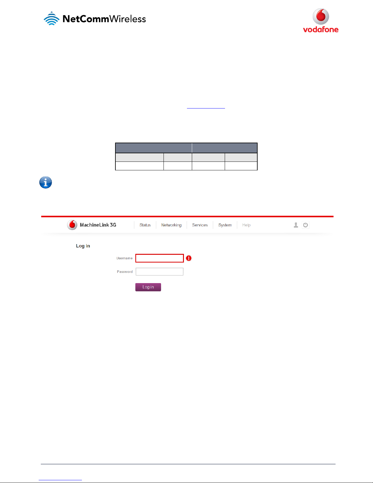
To log in to the web-based user interface of the router:
1. Open a web browser (e.g. Internet Explorer, Firefox, Safari), type
http://192.168.1.1 into the address bar and press Enter. The web-based
user interface login screen is displayed.
2. Enter the login username and password. If this is the first time you are logging in or you have not previously configured the password for
the “root” or “admin” accounts, you can use one of the default account details to log in.
ADMIN MANAGER ACCOUNT ROOT MANAGER ACCOUNT
Username: admin Username: root
Password: admin Password: admin
Table 10 - Management acco unt login details
Note:
•
To access all features of the router, you must use the root manager account.
•
For security reasons, we highly recommend that you change the passwords for the root and admin accounts upon initial
installation. You can do so by navigating via the menu to the System and then Administration page.
Figure 16 – Log in prompt for the web-based user interface
After you have logged in, the Status page is displayed.
Page 19
www.netcommwireless.com and m2m.vodafone.com
Vodafone MachineLink 3G
19
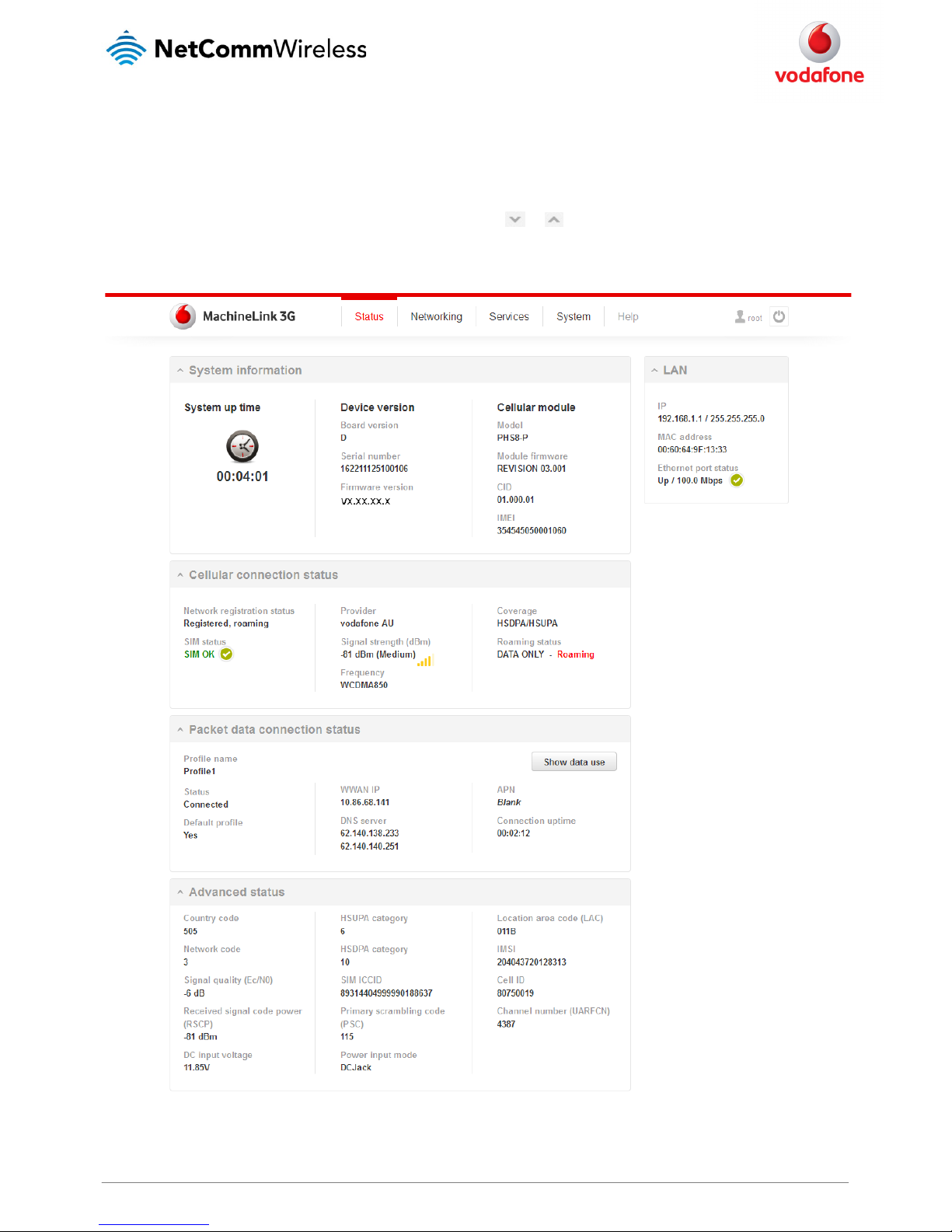
Status
The status page of the web interface provides system related information and is displayed when you log in to the Vodafone MachineLink 3G
management console. The status page shows System information, LAN details, Cellular connection status, Packet data connection status and
Advanced status details. You can toggle the sections from view by clicking the or buttons to show or hide them.
Extra status boxes will appear as additional software features are enabled (e.g. VPN connectivity)
Figure 17 - The Status page
Page 20
20
Vodafone MachineLink 3G
www.netcommwireless.com and m2m.vodafone.com
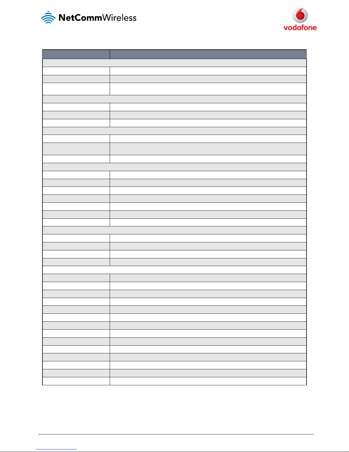
ITEM DEFINITION
System information
System up time The current uptime of the rou ter.
Device version The hardware and software firm ware versions of the router.
Cellular module
The type of phone module, firm ware version of the module, Cellular configuration ID (CID), and the IMEI (Internati onal Mobile
Equipment Identity) of the router.
LAN
IP The IP address and subnet mas k of the router.
MAC address The MAC address of the router.
Ethernet port status Displays the current status o f the Ethernet port and its operating speed.
Cellular connection status
Network registration status / SIM status The status of the SIM card includ ing whether the SIM is registered on the network and whether it is roaming.
Provider / Signal strength (dBm) /
Frequency
This shows the 3G service provider, the current signal stren gth measured in dBm and the frequency on which the router is
operating.
Coverage / Roaming status The type of mobile coverage bei ng received by the router and the roaming status of the SIM.
Packet data conne ction status
Profile name The name of the active profile.
Status The connection status of the active profile.
Default profile Indicates whether the profile is the default profile.
WWAN IP The IP address assigned by the mobile broadband carrier n etwork.
DNS server The DNS servers assigned to th e router by the mobile broadband carrier network.
APN The Access Point Name current ly in use.
Connection uptime The duration of the current co nnection to the mobile broadband network.
Transparent bridge mode
Status The status of the bridged connection mode.
IP The IP address and subnet mas k of the bridged connection.
APN name The Access Point Name you h ave selected for the bridged connection.
Service name The optional service name yo u have chosen for the bridged connection.
Advanced status
Country code The Mobile Country Code (MCC) o f the inserted SIM.
Network code The Mobile Network Code (MNC) of the inserted SIM.
Signal quality ( Ec/Io) A measurement of th e portion of the received signal that is usable. This is basically the signal strength minus the signal noise level.
Received signal code power (RSCP) The power lev el of the signal on the current connection’s pa rticular channel.
DC input voltage Displays the current voltage of the power inp ut source provided via the DC Input jack
HSUPA category Displays the HSUPA c ategory (1-9) for the current uplink
HSDPA category Displays the H SDPA category (1-8) for the current do wnlink.
SIM ICCID The Integrated Circuit Card I dentifier of the SIM card used with the router, a u nique number up to 19 digits in length.
Primary scrambling code (P SC) The Primary scrambling code fo r the current signal.
Power input mode Displays whethe r power is currently being sourced from the PoE E thernet port or from the DC input jack.
Location area code (LAC) The ID of the cell tower grou ping the current signal is broadcasting from.
IMSI The International mobile s ubscriber identity (IMSI) used to identify the router on the cellular network.
Cell ID A unique code that identifies the base station from with in the location area of the current mobile network signal.
Channel number (UARFCN) The channel number of the current 3G/2G connecti on.
Table 11 - Status page item details
Page 21
www.netcommwireless.com and m2m.vodafone.com
Vodafone MachineLink 3G
21
Networking
The Networking section provides configuration options for Wireless WAN, LAN, Routing and VPN connectivity.
Data connection
The data connection has two modes of operation:
Transparent bridge ON
In this mode the router does not manage the status of the connection to the packet data network. The status of the connection is
instead managed by a client device connected behind the router via a PPPoE session. Certain functions of the router are unavailable
when running in transparent bridge mode such as Connect on demand, Routing, VPN, TR-069, Router firewall and Remote access.
As the responsibility of maintaining the connection is passed to a client machine, only that device will have network access.
Transparent bridge OFF
This is the default mode of operation. When transparent bridging is turned off, the router manages the status of the connection
allowing Connect on demand, Routing, VPN, TR-069, Router firewall and Remote access.
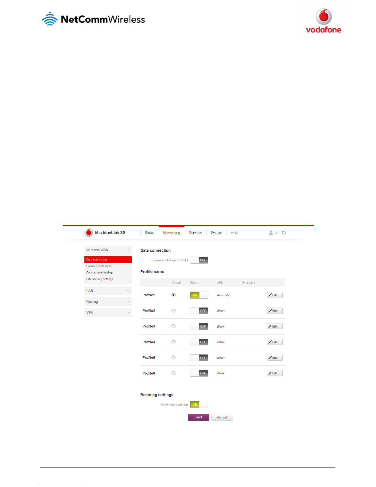
The data connection page allows you to configure and enable/disable up to six connection profiles or to alternatively bridge the data connection
via a PPPoE session.
Each profile refers to a set of configuration items which are used by the router to activate a Packet Data (PDP) context. Under normal scenarios,
you may have a single profile enabled. Multiple profiles can be used for simple fast-switching of PDP settings such as APN, or for advanced
networking configuration where multiple simultaneous PDP contexts may be required.
When the transparent bridge function is off, you can configure the connection profiles by clicking the Edit button to the right of each row.
Figure 18 – Data connection settings ( Transparent bridge off)
Page 22
22
Vodafone MachineLink 3G
www.netcommwireless.com and m2m.vodafone.com
ITEM DEFINITION
Data connectio n
Transparent Bridge (PPPoE) Toggles the transparent bridg e function on and off.
Profile name list
Default
Sets the corresponding profi le to be the default gateway for all outbound traffic e xcept traffic for which there are configured sta tic
route rules or profile routin g settings.
Status Toggles the corresponding profile on and off. If you r carrier supports it, two profiles may be turned on simultaneously.
APN The APN configured for the corr esponding profile.
Username The username used to log on to the corresponding APN.
Roaming settings
Allow data roa ming
When set to ON, the router will allow lo cal devices to access the Wireless WAN network wh en the MachineLink 3G is roaming onto a
foreign network. When set to OFF, the router will deny network access to data s ervices when roaming onto a foreign network. This
setting is ON by default.
Table 12 - Data connection item details
Page 23

www.netcommwireless.com and m2m.vodafone.com
Vodafone MachineLink 3G
23
Connecting to the mobile broadband network
The router supports the configuration of up to six APN profiles; these profiles allow you to configure the settings that the router will use to connect
to the 2G/3G network and switch easily between different connection settings.
For advanced networking purposes, you may activate a maximum of two profiles simultaneously (dependant on network support). When activating
two connection profiles, you should avoid selecting two profiles with the same APN as this can cause only one profile to connect. Similarly,
activating two profiles which are both configured to automatically determine an APN (including two blank APN profiles when using a Vodafone
SIM) can cause a conflict and result in neither profile establishing a connection. We recommend that the two active connection profiles have
differing, manually configured APNs to avoid connection issues and ensure smooth operation.
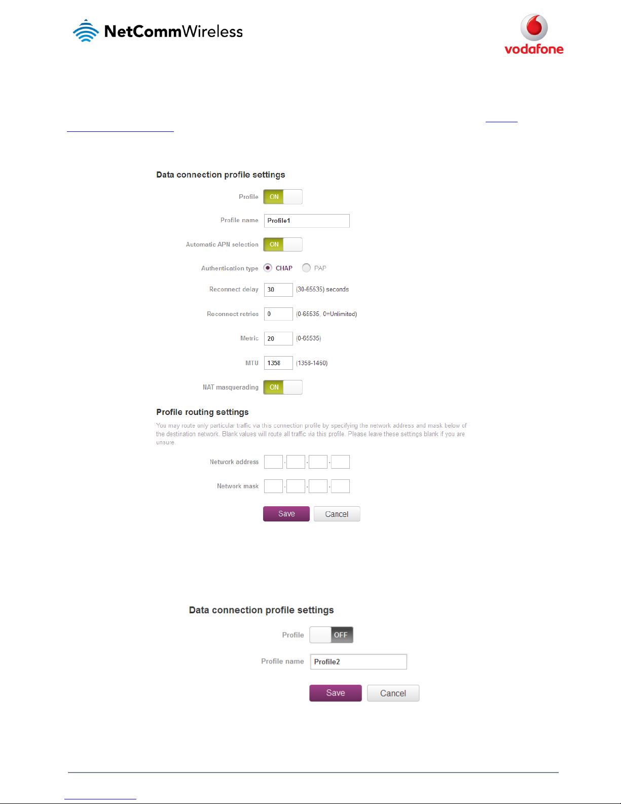
Using a Vodafone Global SIM
When using a Vodafone Global SIM, the router is pre-configured with the APN field blank. A blank APN setting allows the network to determine the
correct APN.
Figure 19 - Data connection profile se ttings - Vodafone Global SIM
Page 24
24
Vodafone MachineLink 3G
www.netcommwireless.com and m2m.vodafone.com
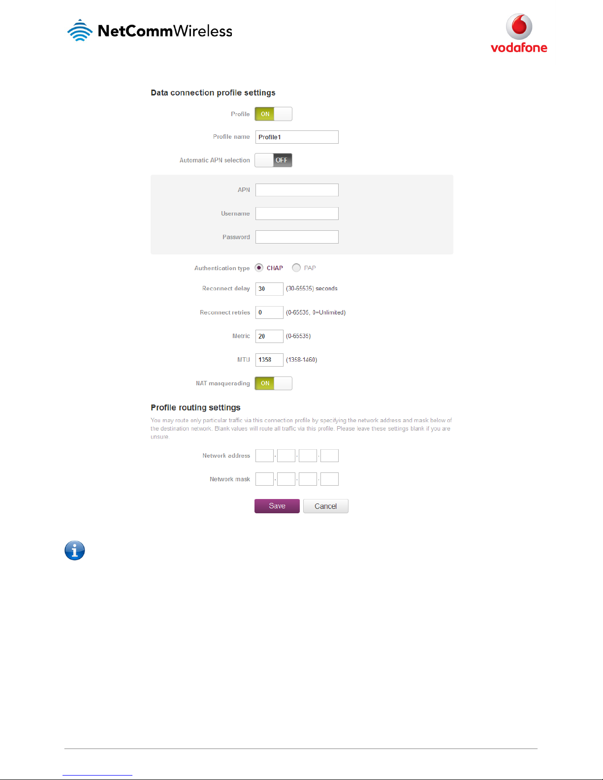
Using a non-Vodafone Global SIM
When using a non-Vodafone Global SIM, the MachineLink 3G Router gives you the option of turning Automatic APN selection on or off. By default,
Profile 1 is configured with Profile1 and Automatic APN set to ON.
When Automatic APN selection is turned on, the router selects an appropriate APN from an internal database of known APNs. If the SIM you have
inserted into the router is not of a known carrier, you may need to manually enter an APN to obtain a network connection. See
manually
configuring a connection profile
for details on entering an APN manually.
To see the automatically selected APN, view the Status page.
Figure 20 - Data connection profile se ttings –Non-Vodafone Globa l SIM - Automatic APN settings
Manually configuring a connection profile
To manually configure a connection profile:
1. Click the Edit button corresponding to the Profile that you wish to modify. The data connection profile settings page is displayed.
Figure 21 - Data connection profile se ttings
Page 25
www.netcommwireless.com and m2m.vodafone.com
Vodafone MachineLink 3G
25
2. Click the Profile toggle key to turn the profile on. Additional settings appear.
Figure 22 - Data connection settings - Profile turned on
Note: The Automatic APN toggle key is not available when using a Vodafone Global SIM.
3. In the Profile name field, enter a name for the profile. This name is only used to identify the profile on the router.
4. When using a SIM other than a Vodafone Global SIM, ensure that the Automatic APN selection toggle key is set to off. If it is not, click it
to toggle it to the off position.
5. In the APN field, enter the APN Name (Access Point Name) and if required, use the Username and Password fields to enter your login
credentials.
6. Next to Authentication type, select the either CHAP or PAP depending on the type of authentication used by your provider.
7. The Reconnect delay field specifies the number of seconds to wait between connection attempts. The default setting of 30 seconds is
sufficient in most cases but you may modify it to wait up to 65535 seconds if you wish.
8. The Reconnect retries field specifies the number of times to attempt to connect to the network if the router fails to establish a
connection. It is set to 0 by default which causes the router to attempt to reconnect indefinitely.
9. The Metric value is used by router to prioritise routes (if multiple are available) and is set to 20 by default. This value is sufficient in most
cases but you may modify it if you are aware of the effect your changes will have on the service.
Page 26

26
Vodafone MachineLink 3G
www.netcommwireless.com and m2m.vodafone.com
10. Use the NAT Masquerading toggle key to turn NAT Masquerading on or off. NAT masquerading, also known simply as NAT is a common
routing feature which allows multiple LAN devices to appear as a single WAN IP via network address translation. In this mode, the router
modifies network traffic sent and received to inform remote computers on the internet that packets originating from a machine behind
the router actually originated from the WAN IP address of the router’s internal NAT IP address. This may be disabled if a framed route
configuration is required and local devices require WAN IP addresses.
11. For advanced networking such as using dual simultaneous PDP contexts, you may wish to configure a particular profile to route only
certain traffic via that profile by configuring a custom address and mask of traffic to send via that profile. To do this, in the Profile routing
settings section, enter the Network address and Network mask of the remote network. If you do not want to use this feature, or are
unsure, please leave these fields blank, which will not designate any particular traffic to be routed via this profile. For more information
on configuring Profile routing settings, see the
Setting a default gateway with two active connection profiles example.
12. Click the Save button when you have finished entering the profile details.
Confirming a successful connection
After configuring a packet data session, and ensuring that one is enabled, click on the Status menu item at the top of the page to return to the
Status page.
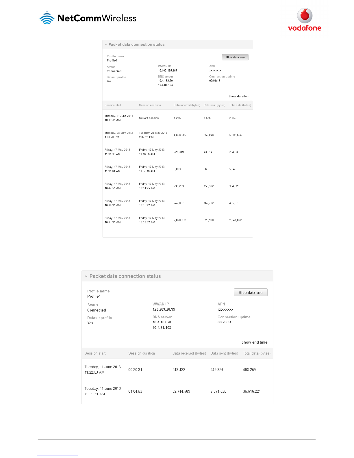
When there is a mobile broadband connection, the Packet data connection status section is expanded showing the details of the connection. To
see details on each connected session, you can click Show data use button.
Figure 23 - Packet data connection s tatus section
Checking data usage
On the Status page, each packet data connection profile has a Show data use button which displays the amount of data received, sent and a total
data usage figure.
To show the data use for a connected profile, click the Show data use button. The data usage for the last 10 sessions is displayed in addition to
the current session.
Page 27
www.netcommwireless.com and m2m.vodafone.com
Vodafone MachineLink 3G
27
Figure 24 - Data usage
Click the Show duration link to toggle the display to show the duration of each session rather than the start and end times.
Figure 25 - Data usage with connectio n duration
Page 28
28
Vodafone MachineLink 3G
www.netcommwireless.com and m2m.vodafone.com
Transparently bridging the mobile broadband connection via PPPoE
If desired, you can have a client device connected to the Ethernet port initiate the mobile broadband connection using a PPPoE session. This is
particularly useful in situations where you wish to provide Wireless WAN data access to an existing router which you want to have full public WAN
IP access and have control over routing functionality.
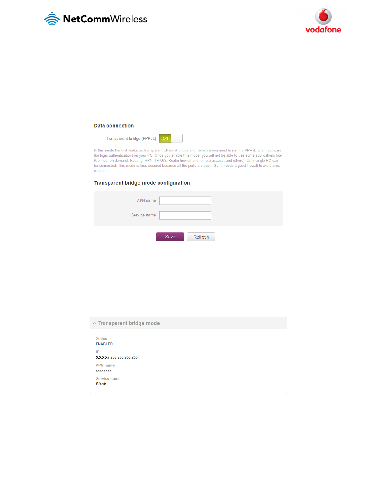
To enable transparent bridging via PPPoE:
1. Click the Networking menu item from the top menu bar.
2. On the Data connection page, click the Transparent bridge (PPPoE) toggle key so that it is ON.
Figure 26 - Transparent bridge configu ration
3. In the APN name field, enter the APN that you wish to use for the mobile broadband connection. If using a Vodafone Global SIM card,
leave the APN name field blank.
4. (Optional) In the Service name field, enter a name that allows you to easily identify the connection.
5. Click the Save button to confirm the settings.
6. Click the Status menu item from the top menu bar to see the transparent bridging status.
Figure 27 - Transparent bridge mode s tatus
7. Next you must configure your downstream device connected via Ethernet to the MachineLink 3G to initiate a network connection a
PPPoE client. The username and password used by the downstream device for the PPPoE session will be passed on and used by the
MachineLink 3G as the packet data (PDP) context authentication settings.
Page 29
www.netcommwireless.com and m2m.vodafone.com
Vodafone MachineLink 3G
29
Connect on demand
The connect on demand feature keeps the Packet Data Protocol (PDP) context deactivated by default while making it appear to locally connected
devices that the router has a permanent connection to the mobile broadband network. When a packet of interest arrives or an SMS wake-up
command is received, the router attempts to establish a mobile broadband data connection. When the data connection is established, the router
monitors traffic and terminates the link when it is idle.
Note: When interesting packets arrive, the recovery time for the wireless WAN connection is approximately 20-30 seconds.
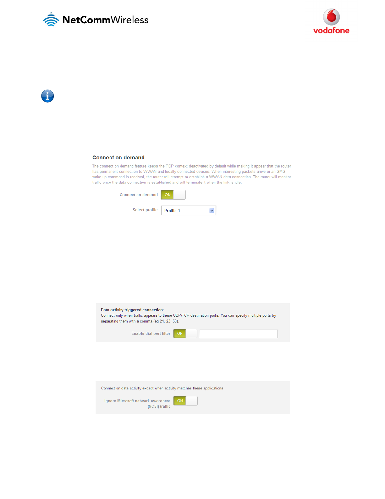
Configuring connect on demand
To configure Connect on demand:
1. Click the Networking menu item from the top menu bar.
2. On the Connect on demand page, click the Connect on demand toggle key so that it is ON.
Figure 28 - Connect on demand configura tion options
3. If you have more than one active connection profile, use the Select profile drop down list to select the profile for which you want to
configure the Connect on demand feature.
Setting the router to dial a connection when traffic is detected on specific ports
In some situations, you may wish to have the internet connection disabled except at times when outbound traffic to a particular external host’s
port is sent to the router. To use this feature, click Enable dial port filter and enter the port number or list of port numbers separated by commas.
When you select this option, all outbound ICMP/TCP/UDP packets to any remote host on the specified port(s) will trigger the connection to dial.
Note that when this feature is enabled, the options to ignore specific packet types are not available.
Figure 29 - Connect on demand - Data activity triggered co nnection
You can allow Microsoft network awareness (NCSI) traffic through but if you prefer that they do not trigger the connection, click the Ignore
Microsoft network awareness (NCSI) traffic toggle key to set it to ON.
Figure 30 - Connect on demand - Ign ore NCSI traffic
Page 30
30
Vodafone MachineLink 3G
www.netcommwireless.com and m2m.vodafone.com
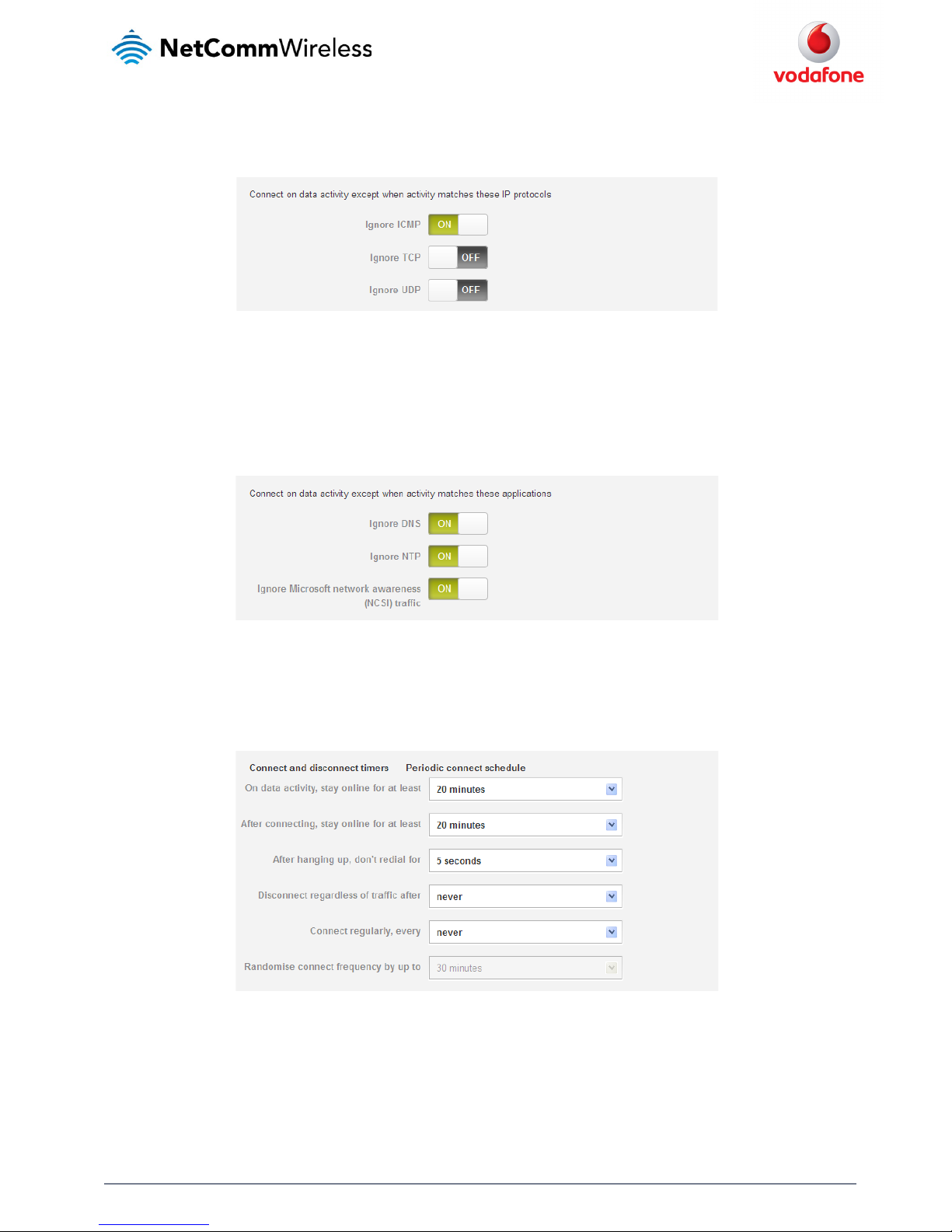
Excluding certain packet types from triggering the connection to dial
Depending on your environment, you might prefer to exclude certain types of traffic passing through the router from triggering the data
connection. You can tell the router to ignore outbound TCP, UDP or ICMP packets. When any of these options are checked the router will not dial a
connection when that type of outbound destined data packet reaches the router from a locally connected device.
Figure 31 - Connect on demand - Excluding IP protocols
Excluding certain application types from triggering the connection to dial
Some devices may generate general traffic as a part of normal operation which you may not want to trigger the data connection. You can set the
router to ignore Domain Name System (DNS), Network Time Protocol (NTP) or Microsoft network awareness (NCSI) traffic from devices behind the
router. When you check the box for these options, it tells the router to ignore the request from that application type and will not dial a connection
when this data type is received.
Figure 32 - Connect on demand - Excluding application types
Setting timers for dial-up and disconnection
The router has a number of timer settings which let you determine when a connection is dialled and when it is disconnected.
Figure 33 - Connect on demand - Connect and disconnect tim ers
Page 31

www.netcommwireless.com and m2m.vodafone.com
Vodafone MachineLink 3G
31
OPTION DESCRIPTION
On data activity, stay online fo r at least
When traffic as per the configu red settings above appear, the router will eith er continue to stay online, or dial a
connection and will not disconnect it for the specified time period (min. 1 minute, max. 1 hour). This timer is
continuously reset througho ut the duration of a dial-up session, whenever data activity is detected matching
the rules above.
After connecting, stay onlin e for at least
This timer configures the router to not hang-up the connection for the specified time pe riod after initially
dialling the connection. This setting cannot be less than the keep online period above. This timer affects th e
connection only once per dial up session, at the beginning of the session.
After hanging up, don’t redial for After a con nection has been disconnected, you can tell the ro uter to rest for a period of time before re-dialling.
Disconnect regardless of traffi c after
Forces the router to discon nect the connection regardless of the traffic pas sing through it. The default setting is
never
.
Connect regularly, every
If you want to have the router dia l a connection at regular intervals, use Connect r egularly, every to specify
the interval between dials. Setting this to
never
effectively disables this option.
The router also features the abi lity to randomise the time at which the first dia l action is performed. This is useful
in situations such as where yo u have numerous routers in an area where a power o utage has occurred. Setting a
random dial time helps to redu ce network congestion when all the routers are po wered on so they do not all try
to connect simultaneously.
When it is set to at least 2 minu tes, you are able to configure the router to randomi se the time it begins to dial.
The randomised dial timer o nly affects the initial dial after the unit powers on or after the settings are saved. For
example, if you configure the ro uter to dial every 2 minutes with a randomised dial time of 1 minute, the router
will dial the initial connection at a time greater th an 2 minutes, but less than 3 minutes. After the firs t dial, the
router will dial the connection e xactly every 2 minutes.
Table 13 - Connect on demand - Connect an d disconnect timers descriptions
Verbose logging
The router provides the option of logging all the data activity which matches the settings for the Connect on demand feature for advanced
troubleshooting purposes. To enable the logging of the Connect on demand feature, click the Log all matched activity to the system log
toggle key to switch it ON. See the System log section for more information.
Figure 34 - Connect on demand - Verbose logging configuration
Manually connecting/disconnecting
There may be times when you need to either force a connection to be made or force a disconnection manually. You can use the Manual connect
and Manual disconnect buttons to do this whenever necessary. The online status of the connection is displayed above the buttons.
Figure 35 - Connect on demand - Online/Offline contro l
When you have finished configuring the options for the Connect on demand feature, click the Save button at the bottom to save your changes.
SMS Wake up
The router can also be woken up by means of an SMS message using the SMS diagnostics feature by sending a zero byte class 1 flash SMS. See the
Diagnostics section for details on using the SMS Wake up function.
Page 32

32
Vodafone MachineLink 3G
www.netcommwireless.com and m2m.vodafone.com
Operator settings
The Operator settings page enables you to select which frequency band you will use for your connection and enables you to scan for available
network operators in your area.
Figure 36 – Band settings
Note: In order to change the cellular band settings, the data connection must be disabled. When you access this page, you are prompted
to disable the data connection if it is already active.
You may want to do this if you’re using the router in a country with multiple frequency networks that may not all support High Speed Packet
Access (HSPA). You can select the router to only connect on the network frequencies that suit your requirements.
Use the Change band drop down list to select the band you wish to use.
The following band settings options are available:
All Bands
GSM All
WCDMA All
GSM 850
GSM 900
GSM 1800
GSM 1900
WCMDA 850
WCDMA 900
WCDMA 800
WCDMA 1900
WCDMA 2100
It is not necessary to change the default setting of All bands in most cases. In fact, locking to a particular band can cause connection difficulties if
the device is moved to a location where the forced band selection is no longer available.
When All bands is selected, the router attempts to find the most suitable band based on the available networks for the inserted SIM card.
The GSM All and the WCDMA all options allow you to force the device to lock to either 2G networks only, or 3G networks only.
Click the Save button to save and apply your selection.
Operator settings
The operator settings feature allows you perform a scan of available networks, and to optionally lock to a particular network returned by the
network scan. To scan for available networks, set the Select operator mode from automatic to Manual then click the scan button. This operation
can take a few minutes and requires that the packet data session be disconnected prior to scanning.
Page 33

www.netcommwireless.com and m2m.vodafone.com
Vodafone MachineLink 3G
33
Figure 37 – Operator settings
A list of the detected 3G service carriers in your area is displayed.
Figure 38 - Detected operator list
Select the most appropriate 3G service from the list shown and click Apply.
When Select operator mode is set to Automatic, the router selects the most appropriate operator based on the inserted SIM card. This is the
default option and is sufficient for most users.
Page 34

34
Vodafone MachineLink 3G
www.netcommwireless.com and m2m.vodafone.com
SIM security settings
The SIM security settings page can be used for authenticating SIM cards that have been configured with a security PIN.
Unlocking a PIN locked SIM
If the SIM card is locked, you will receive a notice when you access the Status page after which you will be directed to the PIN settings page to
enter the PIN. The PIN settings page lists the status of the SIM at the top of the page.
If you are not redirected to the PIN settings page, to unlock the SIM:
a) Click on the Networking menu from the top menu bar, and then click SIM security settings.
Figure 39 - SIM security settings - SIM PIN locked
b) Enter the PIN in the Current PIN field and then enter it again in the Confirm current PIN field to confirm the PIN.
c) If you are placing the router in a remote, unattended location, you may wish to check the Remember PIN option. This feature allows
the router to automatically send the PIN to the SIM each time the SIM asks for it (usually at power up). This enables the SIM to be PIN
locked (to prevent unauthorised re-use of the SIM elsewhere), while still allowing the router to connect to the cellular service.
When this feature is enabled, the PIN you enter when setting the Remember PIN feature is encrypted and stored locally on the router.
The next time the SIM asks the router for the PIN, the router decrypts the PIN and automatically sends it to the SIM without user
intervention.
When this feature is disabled and the SIM is PIN locked and the PIN must be manually entered via the router‘s configuration interface. In
situations where the router will be unattended, this is not desirable.
Note: Select Remember PIN if you do not want to enter the PIN code each time the SIM is inserted.
d) Click the Save button. If successful, the router displays the following screen:
Page 35

www.netcommwireless.com and m2m.vodafone.com
Vodafone MachineLink 3G
35
Enabling/Disabling SIM PIN protection
The security PIN protection can be turned on or off using the PIN protection toggle key.
Figure 40 - PIN Settings
Changing the SIM PIN code
If you would like to change the PIN, click the Change PIN button and enter the current PIN into the Current PIN and Confirm current PIN fields,
then enter the desired PIN into the New PIN and Confirm new PIN fields and click the Save button.
Figure 41 - PIN settings - Change PIN
Page 36

36
Vodafone MachineLink 3G
www.netcommwireless.com and m2m.vodafone.com
When the PIN has been changed successfully, the following screen is displayed:
Figure 42 - SIM security settings – PI N unlock successful
Page 37

www.netcommwireless.com and m2m.vodafone.com
Vodafone MachineLink 3G
37
Unlocking a PUK locked SIM
After three incorrect attempts at entering the PIN, the SIM card becomes PUK (Personal Unblocking Key) locked and you are requested to enter a
PUK code to unlock it.
Note: To obtain the PUK unlock code, you must contact Vodafone.
You will be issued a PUK to enable you to unlock the SIM and enter a new PIN. Enter the new PIN and PUK codes.
Click the Save button when you have finished entering the new PIN and PUK codes.
Figure 43 - SIM security - SIM PU K locked
Page 38

38
Vodafone MachineLink 3G
www.netcommwireless.com and m2m.vodafone.com
LAN
LAN configuration
The LAN configuration page is used to configure the LAN settings of the router and to enable or disable DNS Masquerading.
Figure 44 – LAN configuration settings
The default IP of the Ethernet port is 192.168.1.1 with subnet mask 255.255.255.0 and a Host name of “my.router”. To change the IP address,
Subnet mask or Host name, enter them in the appropriate fields and click the Save button.
Note: If you change the IP address, remember to reboot the router and enter the new IP address into your browser address bar.
DNS masquerading
DNS masquerading allows the router to proxy DNS requests from LAN clients to dynamically assigned DNS servers. When enabled, clients on the
router’s LAN can then use the router as a DNS server without needing to know the dynamically assigned cellular network DNS servers.
With DNS masquerading ON, the DHCP server embedded in the MachineLink 3G hands out its own IP address (e.g. 192.168.1.1) as the DNS server
address to LAN clients. The downstream clients then send DNS requests to the MachineLink which proxies them to the upstream DNS servers.
With DNS masquerading OFF, the DHCP server hands out the upstream DNS server IP addresses to downstream clients directly, so that
downstream clients send DNS requests directly to the upstream DNS servers without being proxied by the MachineLink 3G.
You may also override the DNS Masquerading option by specifying custom DNS Server IP addresses in the DHCP Server configuration mentioned
in the next section of this guide. In this case the DHCP server assigns downstream devices the manually configured addresses and the DNS
Masquerading option is ignored.
In most cases, it is not necessary to disable DNS masquerading but if you need to, click the DNS masquerading toggle key to turn it OFF and then
click the Save button.
Page 39

www.netcommwireless.com and m2m.vodafone.com
Vodafone MachineLink 3G
39
Automatic IP address assignment (DHCP)
The DHCP page is used to adjust the settings used by the router’s built in DHPC Server which assigns IP addresses to locally connected devices.
DHCP relay configuration
In advanced networks configurations where the MachineLink 3G Router should not be responsible for DHCP assignment, but instead an existing
DHCP server is located on the Wireless WAN connection, the clients behind the MachineLink 3G are able to communicate with the DHCP server
when DHCP relay is enabled. This enables the MachineLink 3G to accept client broadcast messages and to forward them onto another subnet.
To configure the router to act as a DHCP relay agent click the DHCP relay toggle key to turn it ON and enter the DHCP server address into the
DHCP server address field. DHCP relay is disabled by default.
Figure 45 – DHCP relay configuration
DHCP configuration
You can manually set the start and end address range to be used to automatically assign addresses within, the lease time of the assigned address,
the default domain name suffix, primary and secondary DNS server, the primary and secondary WINS server, as well as the advanced DHCP settings
such as NTP, TFTP and Option 150/Option 160 (VoIP options).
Figure 46 - DHCP configuration
Page 40

40
Vodafone MachineLink 3G
www.netcommwireless.com and m2m.vodafone.com
OPTION DESCRIPTION
DHCP start range Sets the first IP add ress of the DHCP range
DHCP end range Sets the last IP addres s of the DHCP range
DHCP lease time (seconds) The leng th of time in seconds that DHCP allocated IP addres ses are valid
Default domain name suffix
Specifies the default domai n name suffix for the DHCP clients. A domain name suffix enables users to access a
local server, for example, s erver1, without typing the full domain name server1 .domain.com
DNS server 1 IP address Specifies the primary DNS (Domain Name System) server’s IP address.
DNS server 2 IP address Specifies the secondary DNS (Domain Name System) server’s IP address.
WINS server 1 IP address Specifies the primary WINS (Win dows Internet Name Service) server IP addres s
WINS server 2 IP address Specifies the secondary WINS ( Windows Internet Name Service) server IP address
NTP server (Option 42) Specifies the IP address of the NT P (Network Time Protocol) server
TFTP server (Option 66) Specifies the TFTP (Trivial File Transfer Protocol) server
DHCP option 150
This is used to configure Cisco IP phones. When a Cisco IP phone s tarts, if it is not pre-configured with the IP
address and TFTP address, i t sends a request to the DHCP server to obtain this in formation. Specify the string
which will be sent as a reply to the option 150 request.
DHCP option 160
This is used to configure Polycom IP phones. When a Polycom IP pho ne starts, if it is not pre-configured with the
IP address and TFTP address, it sends a request to the DHCP server to obtain this i nformation. Specify the string
which will be s ent as a reply to the option 160 requ est.
Enter the desired DHCP options and click the Save button.
Address reservation list
DHCP clients are dynamically assigned an IP address as they connect, but you can reserve an address for a particular device using the address
reservation list.
Figure 47 – DHCP – Address reservation list
To add a device to the address reservation list:
1. Click the +Add button.
2. In the Computer name field enter a name for the device.
3. In the MAC address field, enter the device’s MAC address.
4. In the IP address fields, enter the IP address that you wish to reserve for the device.
5. If the Enable toggle key is not set to ON, click it to switch it to the ON position.
6. Click the Save button to save the settings.
Page 41

www.netcommwireless.com and m2m.vodafone.com
Vodafone MachineLink 3G
41
Dynamic DHCP client list
The Dynamic DHCP client list displays a list of the DHCP clients. If you want to reserve the current IP address for future use, click the Clone button
and the details will be copied to the address reservation list fields. Remember to click the Save button under the Address reservation list
section to confirm the configuration.
Figure 48 - Dynamic DHC P client list
Page 42

42
Vodafone MachineLink 3G
www.netcommwireless.com and m2m.vodafone.com
Routing
Static
Static routing is the alternative to dynamic routing used in more complex network scenarios and is used to facilitate communication between
devices on different networks. Static routing involves configuring the routers in your network with all the information necessary to allow the
packets to be forwarded to the correct destination. If you change the IP address of one of the devices in the static route, the route will be broken.
Figure 49 - Static routing list
Some routes are added by default by the router on initialisation such as the Ethernet subnet route for routing to a device on the Ethernet subnet.
Adding Static Routes
To add a new route to the static routing list, click the +Add button. The Static routes page appears.
1. In the Route name field, type a name for the route so that it can be identified in the static routing list.
2. From the Network interface drop down list, select the interface for which you would like to create a static route.
3. In the Destination IP address field, enter the IP address of the destination of the route.
4. In the IP subnet mask field, enter the subnet mask of the route.
5. In the Gateway IP address field, enter the IP address of the gateway that will facilitate the route.
6. In the Metric field enter the metric for the route. The metric value is used by the router to prioritise routes. The lower the value, the
higher the priority. To give the route the highest priority, set it to 0.
7. Click the Save button to save your settings.
Page 43

www.netcommwireless.com and m2m.vodafone.com
Vodafone MachineLink 3G
43
Figure 50 - Adding a static route
Setting a default gateway with two active connection profiles
When two connection profiles are active, all outbound traffic will be sent via the profile configured as the default gateway (See
Data connection). If
you wish to configure traffic to a network to go through a particular gateway, there are two methods available:
1. Use the static routing method described above.
2. Add the details of the remote network to the connection profile configuration.
For example:
Figure 51 – Routing - Default gateway with t wo active connection profiles
Page 44

44
Vodafone MachineLink 3G
www.netcommwireless.com and m2m.vodafone.com
In the example configuration above, Profile 1 and Profile 2 are both active and Profile 1 is configured as the default gateway. All outbound traffic is
sent via Profile 1.
To specify that outbound traffic to remote network 123.121.120.X goes via Profile 2:
1. Click the Networking menu at the top of the screen and then click the Edit button next to Profile 2.
Figure 52 – Routing - Edit Profile 2
2. Scroll to the bottom of the window and in the Profile routing settings section, enter the address of the remote network and the subnet
mask. A subnet is an identifiably separate part of a network and a subnet mask is the notation used to denote the subnet. Take care
when configuring the subnet mask that the internal IP address of the router is in a different subnet than the remote network.
Figure 53 - Routing - adding remote network address and mask
3. Click the Save button to save the settings. All outbound traffic to 123.121.120.X addresses are now routed through Profile 2.
Page 45

www.netcommwireless.com and m2m.vodafone.com
Vodafone MachineLink 3G
45
Active routing list
Static routes are displayed in the Active routing list.
Figure 54 - Active routing list
Deleting static routes
From the static routing list, click the icon to the right of the entry you wish to delete.
Figure 55 - Deleting a static route
Page 46

46
Vodafone MachineLink 3G
www.netcommwireless.com and m2m.vodafone.com
RIP
RIP (Routing Information Protocol) is used for advertising routes to other routers. Thus all the routes in the router’s routing table will be advertised
to other nearby routers. For example, the route for the router’s Ethernet subnet could be advertised to a router on the PPP interface side so that a
router on this network will know how to route to a device on the router’s Ethernet subnet. Static routes must be added manually according to your
requirements. See
Adding Static Routes.
Note: Some routers will ignore RIP.
Figure 56 - RIP configuration
To enable Routing Information Protocol (RIP)
1. Click the RIP toggle key to switch it to the ON position.
2. Using the Version drop down list, select the version of RIP that you would like to use.
3. Click the Save button to confirm your settings.
Page 47

www.netcommwireless.com and m2m.vodafone.com
Vodafone MachineLink 3G
47
Redundancy (VRRP)
Virtual Router Redundancy Protocol (VRRP) is a non-proprietary redundancy protocol designed to increase the availability of the default gateway
servicing hosts on the same subnet. This increased reliability is achieved by advertising a “virtual router” (an abstract representation of master and
backup routers acting as a group) as a default gateway to the host(s) instead of one physical router. Two or more physical routers are then
configured to stand for the virtual router, with only one doing the actual routing at any given time. If the current physical router that is routing the
data on behalf of the virtual router fails, an arrangement is made for another physical router to automatically replace it. The physical router that is
currently forwarding data on behalf of the virtual router is called the master router.
Master routers have a priority of 255 and backup router(s) can have a priority between 1 and 254.
A virtual router must use 00-00-5E-00-01-XX as its (MAC) address. The last byte of the address (XX) is the Virtual Router Identifier (VRID), which is
different for each virtual router in the network. This address is used by only one physical router at a time, and is the only way that other physical
routers can identify the master router within a virtual router.
Figure 57 - VRRP configuration
To configure VRRP, configure multiple devices as follows and connect them all via an Ethernet network switch to downstream devices.
1. Click the Redundancy (VRRP) toggle key to activate VRRP.
2. In the Virtual ID field, enter an ID between 1 and 255. This is the VRRP ID which is different for each virtual router on the network.
3. In the Router priority field, enter a value for the priority – a higher value is a higher priority.
4. The Virtual IP address field is used to specify the VRRP IP address – this is the virtual IP address that both virtual routers share.
5. Click the Save button to save the new settings.
Note: Configuring VRRP changes the MAC address of the Ethernet port and therefore if you want to resume with the web configuration
you must use the new IP address (VRRP IP) or on a command prompt type:
arp –d <ip address>
(i.e.
arp –d 192.168.1.1)
to clear the arp cache.(old MAC address).
Page 48

48
Vodafone MachineLink 3G
www.netcommwireless.com and m2m.vodafone.com
Port forwarding
The Port forwarding list is used to configure the Network Address Translation (NAT) rules currently in effect on the router.
Figure 58 – Port forwarding list
The purpose of the port forwarding feature is to allow mapping of inbound requests to a specific port on the WAN IP address to a device connected
on the Ethernet interface.
Adding a port forwarding rule
To create a new port forwarding rule:
1. Click the +Add button. The port forwarding settings screen is displayed.
2. Use the Protocol drop down list to select the type of protocol you want to use for the rule. The protocols selections available are TCP,
UDP and All.
3. In the Source IP address field, enter a “friendly” address that is allowed to access the router or a wildcard IP address (0.0.0.0) that allows
all IP addresses to access the router.
4. The Source port range (From) and (To) fields are used to specify the port(s) on the source side that are to be forwarded. This allows
you to send a range of consecutive port numbers by entering the first in the range in the (From) field and the last in the range in the
(To) field. To forward a single port, enter the port in the (From) field and repeat it in the (To) field.
5. In the Destination IP address field, enter the IP address of the client to which the traffic should be forwarded.
6. The Destination port range (From) and (To) fields are used to specify the port(s) on the destination side that are to be forwarded. If the
Source port range specifies a single port then the destination port may be configured to any port. If the Source port range specifies a
range of port numbers then the Destination port range must be the same as the Source port range.
7. Click the Save button to confirm your settings.
Figure 59 - Port forwarding settings
To delete a port forwarding rule, click the button on the Port forwarding list for the corresponding rule that you would like to delete.
Page 49

www.netcommwireless.com and m2m.vodafone.com
Vodafone MachineLink 3G
49
DMZ
The Demilitarised Zone (DMZ) allows you to configure all incoming traffic on all protocols to be forwarded to a selected device behind the router.
This feature can be used to avoid complex port forwarding rules, but it exposes the device to untrusted networks as there is no filtering of what
traffic is allowed and what is denied.
The DMZ configuration page is used to specify the IP Address of the device to use as the DMZ host.
Figure 60 - DMZ configuration
1. Click the DMZ toggle key to turn the DMZ function ON.
2. Enter the IP Address of the device to be the DMZ host into the DMZ IP address field.
3. Click the Save button to save your settings.
MAC / IP / Port filtering
The MAC/IP/Port filter feature allows you apply a policy to the traffic that passes through the router, both inbound and outbound, so that network
access can be controlled. When the filter is enabled with a default rule of “Accepted”, all connections will be allowed except those listed in the
“Current MAC / IP / Port filtering rules in effect” list. Conversely, when the default rule is set to “Dropped”, all connections are denied except for
those listed in the filtering rules list.
Figure 61 - MAC / IP / Port filtering
Note: When enabling MAC / IP / Port filtering and setting the default rule to “Dropped”, you should ensure that you have first added a
filtering rule which allows at least one known MAC/IP to access the router, otherwise you will not be able to access the user interface of
the router without resetting the router to factory default settings.
Creating a MAC / IP / Port filtering rule
To create a filtering rule:
1.
Click the MAC / IP / Port filtering toggle key to switch it to the ON position.
2.
Using the Default Rule (inbound/forward) drop down list, select the default action for the router to take when traffic reaches it. By
default, this is configured to Accepted. If you change this to Dropped, you should first configure a filter rule that allows at least one
device access to the router, otherwise you will effectively be locked out of the router.
3.
Click the Save button to confirm the default rule.
4.
In the Current MAC / IP / Port filtering rules in effect section, click the +Add button.
Page 50

50
Vodafone MachineLink 3G
www.netcommwireless.com and m2m.vodafone.com
Figure 62 - Current MAC / IP/ Port filterin g rules in effect
5. Enter the details of the rule in the section that is displayed and click the Save button.
Figure 63 - MAC / IP / Port filtering se ttings
OPTION DESCRIPTION
Bound
Use the drop down list to select the direction of the traffic for which you want to apply to the rule. Inbound
refers to all traffic that is en tering the router including data entering from the WAN and the LAN. Outbound
refers to all traffic exiting the ro uter including traffic leaving in the direction of the WAN and traffic leaving in the
direction of the LAN. Forward specifies traf fic that enters on the LAN or WAN side and is f orwarded to the
opposite end.
Protocol
Use the drop down list to select the protocol for the rule. You can have the rule ap ply to All protocols, TCP,
UDP, UDP/TCP or I CMP.
MAC address Enter the MAC address in six groups of two hexadecimal digits separated by colons (:). e.g. 00:40:F4:CE:FA:1E
Source IP address Enter the IPv4 address that the t raffic originates from and the subnet mask using CIDR notation.
Source port range (From) – (To)
Only appears for TCP, UDP and U DP/TCP options. Use these fields to specify a po rt or range of ports from the
source side to use for the rule. To specify a sing le port, repeat it in both the (From) and (T o) fields.
Destination IP address Enter the IPv4 address that the t raffic is destined for and the subnet mask using CIDR notation.
Destination port range (Fro m) – (To)
Only appears for TCP, UDP and U DP/TCP options. Use these fields to specify a po rt or range of ports on the
destination side to use for the rule. To speci fy a single port, repeat it in both the (Fro m) and (To) fields.
Action
Select the action to take for tra ffic which meets the above criteria. You can choo se to Accept or Drop packets.
When the default rule is set to Accept, you cannot create a rule with an Acc ept action since the rule is
redundant. Likewise, if the de fault rule is set to Dropped you cannot create a rule with a Drop action.
Comment [Optional] Use this field to en ter a comment as a meaningful description of the ru le.
Table 14 - Current MAC / I P / Port filtering rules in effect
6. The new rule is displayed in the filtering rules list. You can edit the rule by clicking the button or delete the rule by clicking
the button.
Page 51

www.netcommwireless.com and m2m.vodafone.com
Vodafone MachineLink 3G
51
Figure 64 - Completed filtering rule
Page 52

52
Vodafone MachineLink 3G
www.netcommwireless.com and m2m.vodafone.com
VPN
A Virtual Private Network (VPN) is a tunnel providing a private link between two networks or devices over a public network. Data to be sent via a
VPN needs to be encapsulated and as such is generally not visible to the public network.
The advantages of a VPN connection include:
Data Protection
Access Control
Data Origin Authentication
Data Integrity
Each VPN connection has different configuration requirements. The following pages detail the configuration options available for the different
VPN connection types.
Note: The following descriptions are an overview of the various VPN options available. More detailed instructions are available in separate
whitepapers on the NetComm Wireless website.
IPSec
IPSec operates on Layer 3 of the OSI model and as such can protect higher layered protocols. IPSec is used for both site to site VPN and Remote
Access VPN. The Vodafone MachineLink 3G supports IPsec end points and can be configured with Site to Site VPN tunnels with third party VPN
routers.
Configuring an IPSec VPN
From the menu at the top of the screen, click Networking and under the VPN section, click IPSec. A list of configured IPSec VPN connections is
displayed.
Figure 65 - IPSec VPN List
Click the +Add button to begin configuring an IPSec VPN connection.
Page 53

www.netcommwireless.com and m2m.vodafone.com
Vodafone MachineLink 3G
53
Figure 66 – IPSec profile edit
Page 54

54
Vodafone MachineLink 3G
www.netcommwireless.com and m2m.vodafone.com
The following table describes each of the fields of the IPSec VPN Connection Settings page.
ITEM DEFINITION
IPSec profile Enables or disables th e VPN profile.
Profile name A name used to identify the VPN connection profile.
Remote IPSec server address Th e IP address of the IPSec server.
Remote LAN address Enter the IP address of the remote n etwork for use on the VPN connection.
Remote LAN subnet mask Enter the subnet mask in use on the remote network.
Local LAN address Enter the IP address of the local network for us e on the VPN connection.
Local LAN subnet mask Enter the subnet mask in use on the local net work.
Encapsulation type Select the encapsulation p rotocol to use with the VPN connection. You can choose ESP, AH or Any.
IKE Mode Select the IKE mode to use with the VPN connection. You can choose Main, Aggressive or Any.
PFS Choose whether Perfect Forward Secrecy is ON or OFF for the VPN conn ection.
IKE encryption Select the cipher typ e to use for the Internet Key Exchange.
IKE hash Select the IKE Hash type to use for the V PN connection. The hash is used for authenticatio n of packets for the key exchange.
IPSec encryption Select the IPSec encryption type to use with the VPN connecti on.
IPSec hash Select the IPSec hash type to use for the VPN connection. The hash is used for authentication of packets for the VPN conn ection.
DH group Select the desired Diffie-Hellman group to use. Higher groups are more secure but also require longer to generate a key.
DPD action Select th e desired Dead Peer Detection action. This is the action to take when a dead Internet Key Excha nge Peer is detected.
DPD keep alive time Enter the time in seconds for the interval bet ween Dead Peer Detection keep alive messages.
DPD timeout Enter the time in seconds of no response from a peer before D ead Peer Detection times out.
IKE rekey time Enter the time in seconds between chang es of the encryption key. To disable changing the key, s et this to 0.
SA life time Enter the time in seconds for the se curity association lifetime.
Key Mode
Select the type of key mode in u se for the VPN connection. You can select from:
• Pre Shared Key
• RSA keys
• Certificates
Pre-shared key The pre-shared key is the key that peers used to authenticate ea ch other for Internet Key Exchange.
Remote ID Specifies the domain name of the remote network.
Local ID Specifies the domain name of the loca l network.
Update time Displays the last time the key was updated.
Local RSA key upload Select the RSA key file for the local router here by clicking the Browse button.
Remote RSA key upload Select the RSA key fi le for the remote router here by clicking the Brow se button.
Private key passphrase The Private key passphrase of the router is the passphrase used when generatin g the router’s private key using OpenSSL CA.
Key / Certificate
Select the type of key or certifi cate to use for authentication. You can select L ocal private key, Local public certificate, Remote
public certificate, CA certificate, CRL certificate.
IPSec certificate upload Select the IPSec certifi cate to upload by clicking the Browse button.
Table 15 - IPSec Configurati on Items
Page 55

www.netcommwireless.com and m2m.vodafone.com
Vodafone MachineLink 3G
55
OpenVPN
OpenVPN is an open source virtual private network (VPN) program for creating point-to-point or server-to-multi-client encrypted tunnels between
host computers. It can traverse network address translation (NAT) and firewalls and allows authentication by certificate, pre-shared key or
username and password. OpenVPN works well through proxy servers and can run over TCP and UDP transports. Support for OpenVPN is available
on several operating systems, including Windows, Linux, Mac OS, Solaris, OpenBSD, FreeBSD, NetBSD and QNX.
Configuring an Open VPN server
From the menu at the top of the screen, click Networking and from the VPN section on the left, click OpenVPN. A list of configured OpenVPN
VPN connections is displayed.
Figure 67 - OpenVPN VPN List
Click the +Add button for the type of OpenVPN server/client you would like to configure.
OpenVPN server
To configure an OpenVPN server:
1. Click the OpenVPN profile toggle key to switch it to the ON position.
2. Type a name for the OpenVPN server profile you are creating.
3. Use the Type drop down list to select the interface type for the OpenVPN Server. The TAP virtual interface is used to transport IP, non-IP
or IPv6 traffic. It simulates a data link layer device (i.e. bridge) and operates with layer 2 frames such as Ethernet frames. The TUN virtual
interface transports IP traffic only. It simulates a network layer device (i.e. router) and operates with layer 3 packets.
4. Use the Server port field to select a port number and then use the drop down list to select a packet type to use for your OpenVPN
Server. The default OpenVPN port is 1194 and default packet type is UDP.
5. In the VPN network address and VPN network subnet mask fields, enter the IP address and network subnet mask to assign to your
VPN. This is ideally an internal IP address which differs from your existing address scheme.
6. Next to Diffie-Hellman parameters, click the Generate DH button. This will create an encryption key to secure your OpenVPN
connection.
7. Under Server Certificates, enter the required details. All fields must be completed. The Country field must consist of two characters
only. When the details have been entered, click the Generate CA certificate button to generate the Certificate Authority (CA) certificate
based on this information.
8. Under the Server certificates section, select the Authentication type that you would like to use for the OpenVPN Server.
Note: Because the Diffie-Hellman parameters are generated randomly, the time it takes to generate the parameters differs each time. In
some cases it can take up to 30 minutes to generate. Please be patient.
Page 56

56
Vodafone MachineLink 3G
www.netcommwireless.com and m2m.vodafone.com
Certificate Authentication
a) In the Certificate Management section, enter the required details to create a client certificate. All fields are required. When you have
finished entering the details, click the Generate button.
Figure 68 - OpenVPN server configura tion – Certificate management
b) When it is done, you can click the Download P12 button or the Download TGZ button to save the certificate file depending on which
format you would like. If for some reason the integrity of your network has been compromised, you can return to this screen and use the
Certificate drop down list to select the certificate and then press the Revoke button to disable it.
c) Optional: To inform the OpenVPN server of the network address scheme of the currently selected certificate, enter the network address
and network subnet mask in the respective fields and click the Set network information button. If you do not enter the remote subnet
here, any packet requests from the server to the client will not be received by the client network because it is not aware of the remote
client’s subnet.
Page 57

www.netcommwireless.com and m2m.vodafone.com
Vodafone MachineLink 3G
57
Figure 69 – OpenVPN server pro file settings
Page 58

58
Vodafone MachineLink 3G
www.netcommwireless.com and m2m.vodafone.com
Username / Password Authentication
a) In the Username/Password section, enter the username and password you would like to use for authentication on the OpenVPN Server.
Click the Download CA TGZ button or the Download CA certificate button to save the certificate file depending on the certificate format
you require. This file will need to be provided to the client.
Note: If you wish to have more than one client connect to this OpenVPN server, you must use Certificate authentication mode as
Username/Password only allows for a single client connection.
Figure 70 - OpenVPN Serv er – Username / Password section
b) Optional: To inform the OpenVPN server of the network address scheme of the currently selected certificate, enter the network address
and network subnet mask in the respective fields and click the Set network information button. If you do not enter the remote subnet
here, any packet requests from the server to the client will not be received by the client network because it is not aware of the remote
client’s subnet.
c) When you have finished entering all the required information, click Save to finish configuring the OpenVPN server.
Configuring an OpenVPN Client
1. Click the OpenVPN profile toggle key to switch it to the ON position.
2. In the Profile name field, type a name for the OpenVPN client profile you are creating.
3. In the Server IP address field, type the WAN IP address of the OpenVPN server.
4. Use the Server port field to select a port number and then use the drop down list to select a packet type to use for the OpenVPN server.
The default OpenVPN port is 1194 and default packet type is UDP.
5. Use the Type drop down list to select the interface type for the OpenVPN Server. The TAP virtual interface is used to transport IP, non-IP
or IPv6 traffic. It simulates a data link layer device (i.e. bridge) and operates with layer 2 frames such as Ethernet frames. The TUN virtual
interface transports IP traffic only. It simulates a network layer device (i.e. router) and operates with layer 3 packets.
6. If the Default gateway option is applied on the OpenVPN client page, the OpenVPN server will enable connections to be made to other
client networks connected to it. If it is not selected, the OpenVPN connection allows for secure communication links between this
router and the remote OpenVPN server only.
7. Use the Authentication type options to select the Authentication type that you would like to use for the OpenVPN client.
Page 59

www.netcommwireless.com and m2m.vodafone.com
Vodafone MachineLink 3G
59
Certificate Authentication
In the Certificate upload section at the bottom of the screen, click the Browse button and locate the certificate file you downloaded when you
configured the OpenVPN server. When it has been selected, click the Upload button to send it to the router.
Figure 71 - OpenVPN clien t - Certificate upload
Username / Password Authentication
a) Enter the username and password to authenticate with the OpenVPN server.
Figure 72 - OpenVPN Clie nt - Username/Password section
b) Use the Browse button to locate the CA certificate file you saved from the OpenVPN Server and then press the Upload button to send it
to the router.
c) Click the Save button to complete the OpenVPN Client configuration.
Configuring an OpenVPN P2P Connection
To configure an OpenVPN peer-to-peer connection:
1. Set the OpenVPN profile toggle key to switch it to the ON position.
2. In the Profile name field, type a name for the OpenVPN P2P profile you are creating.
3. On the router designated as the master, leave the Server IP address field empty. On the router designated as the slave, enter the WAN
IP address of the master.
Page 60

60
Vodafone MachineLink 3G
www.netcommwireless.com and m2m.vodafone.com
Figure 73 - OpenVPN P2P m ode settings
4. Use the Server port field to select a port number and then use the drop down list to select a packet type to use for the OpenVPN server.
The default OpenVPN port is 1194 and default packet type is UDP.
5. In the Local IP address and Remote IP address fields, enter the respective local and remote IP addresses to use for the OpenVPN tunnel.
The slave should have the reverse settings of the master.
6. Under the Remote network section, enter the network Address and network Subnet mask. The Network Address and Network Mask
fields inform the Master node of the LAN address scheme of the slave.
7. Press the Generate button to create a secret key to be shared with the slave. When the timestamp appears, you can click the Download
button to save the file to exchange with the other router.
8. When you have saved the secret key file on each router, use the Browse button to locate the secret key file for the master and then
press the Upload button to send it to the slave. Perform the same for the other router, uploading the slave’s secret key file to master.
9. When they are uploaded click the Save button to complete the peer-to-peer OpenVPN configuration.
Page 61

www.netcommwireless.com and m2m.vodafone.com
Vodafone MachineLink 3G
61
PPTP client
The Point-to-Point Tunnelling Protocol (PPTP) is a method for implementing virtual private networks using a TCP and GRE tunnel to encapsulate
PPP packets. PPTP operates on Layer 2 of the OSI model and is included on Windows computers.
Configuring the PPTP Client
To configure the PPTP client:
1. From the menu bar at the top of the screen, click Networking and then from the VPN section on the left side of the screen, click PPTP
client. The PPTP client list is displayed.
Figure 74 - PPTP client list
2. Click the +Add button to begin configuring a new PPTP client profile. The PPTP client edit screen is displayed.
Figure 75 - VPN PPTP clie nt edit
3. Click the Enable PPTP client toggle key to switch it to the ON position.
4. In the Profile name list, enter a profile name for the tunnel. This may be anything you like and is used to identify the tunnel on the
router.
5. Use the Username and Password fields to enter the username and password for the PPTP account.
6. In the PPTP server address field, enter the IP address of the PPTP server.
Page 62

62
Vodafone MachineLink 3G
www.netcommwireless.com and m2m.vodafone.com
7. From the Authentication type drop down list, select the Authentication type used on the server. If you do not know the authentication
method used, select any and the router will attempt to determine the correct authentication type for you. There are 5 authentication
types you can choose from:
a) CHAP – uses a three way handshake to authenticate the identity of a client.
b) MS-CHAP v1 – This is the Microsoft implementation of the Challenge Handshake Authentication Protocol for which support was
dropped in Windows® Vista.
c) MS-CHAP v2 - This is the Microsoft implementation of the Challenge Handshake Authentication Protocol which was introduced in
Windows® NT 4.0 and is still supported today.
d) PAP – The Password Authentication Protocol uses a password as a means of authentication and as such, is commonly supported.
PAP is not recommended because it transmits passwords unencrypted and is not secure.
e) EAP – Extensible Authentication Protocol. An Authentication protocol commonly used in wireless networks.
8. The metric value helps the router to prioritise routes and must be a number between 0 and 65535. The default value is 30 and should
not be modified unless you are aware of the effect your changes will have.
9. The Use peer DNS option allows you to select whether the remote clients will use the Domain Name Server of the PPTP server. Click
the toggle key to set this to ON or OFF as required.
10. NAT masquerading allows the router to modify the packets sent and received to inform remote computers on the internet that
packets originating from a machine behind the router actually originated from the WAN IP address of the router’s internal NAT IP
address. Click the toggle key to switch this to the ON position if you want to use this feature.
11. Set default route to PPTP sets all outbound data packets to go out through the PPTP tunnel. Click the toggle key to switch this to the
ON position if you want to use this feature.
12. Select whether to use MPPE. MPPE stands for Microsoft Point-to-Point Encryption and is used to encrypt data across the virtual private
network. The MPPE option is enabled by default.
13. Enter any extra customised PPP option.
14. The Verbose logging option sets the router to output detailed logs regarding the PPTP connection in the System Log section of the
router interface.
15. The Reconnect delay is the time in seconds that the router will wait before attempting to connect to the PPTP server in the event that
the connection is broken. The minimum time to wait is 30 seconds so as to not flood the PPTP server with connection requests, while
the maximum time to wait is 65335 seconds.
16. The Reconnect retries is the number of connection attempts that the router will make in the event that the PPTP connection goes
down. If set to 0, the router will retry the connection indefinitely, otherwise the maximum number of times to retry cannot be greater
than 65335.
17. Click the Save button to save the changes. The VPN will attempt to connect after your click Save. Click the Status button at the top left
of the interface to return to the status window and monitor the VPN’s connection state.
Page 63

www.netcommwireless.com and m2m.vodafone.com
Vodafone MachineLink 3G
63
GRE tunnelling
The Generic Route Encapsulation (GRE) protocol is used in addition to Point-to-Point Tunnelling Protocol (PPTP) to create VPNs (virtual private
networks) between clients and servers or between clients only. Once a PPTP control session establishes the VPN tunnel GRE is used to securely
encapsulate the data or payload.
Configuring GRE tunnelling
To configure GRE tunnelling:
1. From the menu bar at the top of the screen, click Networking and then from the VPN section on the left side of the screen, click PPTP
client. The PPTP client list is displayed.
Figure 76 - GRE client list
2. Click the +Add button to begin configuring a new GRE tunnelling client profile. The GRE client edit screen is displayed.
Figure 77 – GRE client edit
3. Click the Enable VPN toggle key to switch it to the ON position.
4. In the Profile name, enter a profile name for the tunnel. This may be anything you like and is used to identify the tunnel on the router.
5. In the GRE server address field, enter the IP address of the GRE server.
6. In the Local tunnel address field, enter the IP address you want to assign the tunnel locally.
Page 64

64
Vodafone MachineLink 3G
www.netcommwireless.com and m2m.vodafone.com
7. In the Remote tunnel address field, enter the IP address you want to assign to the remote tunnel.
8. In the Remote network address field, enter the IP address scheme of the remote network.
9. In the Remote network/mask field, enter the subnet mask of the remote network.
10. The TTL (Time To Live) field is an 8-bit field used to remove an undeliverable data packet from a network to avoid unnecessary network
traffic across the internet. The default value of 255 is the upper limit on the time that an IP datagram can exist. The value is reduced by
at least one for each hop the data packet takes to the next router on the route to the datagram’s destination. If the TTL field reaches
zero before the datagram arrives at its destination the data packet is discarded and an error message is sent back to the sender.
11. The Reconnect delay is the time in seconds that the router will wait before attempting to connect to the GRE server in the event that
the connection is broken. The minimum time to wait is 30 seconds so as to not flood the GRE server with connection requests, while the
maximum time to wait is 65335 seconds.
12. The Reconnect retries is the number of connection attempts that the router will make in the event that the GRE connection goes
down. If set to 0, the router will retry the connection indefinitely, otherwise the maximum number of times to retry cannot be greater
than 65335.
13. Click the Save button to save the changes. The VPN will attempt to connect after your click Save. Click the Status button at the top left
of the interface to return to the status window and monitor the VPN’s connection state.
Page 65

www.netcommwireless.com and m2m.vodafone.com
Vodafone MachineLink 3G
65
Services
Dynamic DNS
The DDNS page is used to configure the Dynamic DNS feature of the router. A number of Dynamic DNS hosts are available from which to select.
Figure 78 – Dynamic DNS settings
Dynamic DNS provides a method for the router to update an external name server with the current WAN IP address.
To configure dynamic DNS:
1. Click the DDNS configuration toggle key to switch it to the ON position.
2. From the Dynamic DNS drop down list, select the Dynamic DNS service that you wish to use. The available DDNS services available are:
www.dhs.org
www.dyndns.org
www.dyns.cx
www.easydns.com
www.justlinux.com
www.ods.org
www.tzo.com
www.zoneedit.com
3. In the Username and Password fields, enter the logon credentials for your DDNS account. Enter the password for the account again in
the Verify password field.
4. Click the Save button to save the DDNS configuration settings.
Page 66

66
Vodafone MachineLink 3G
www.netcommwireless.com and m2m.vodafone.com
Network time (NTP)
The NTP (Network Time Protocol) settings page allows you to configure the Vodafone MachineLink 3G to synchronise its internal clock with a
global Internet Time server and specify the time zone for the location of the router. This provides an accurate timekeeping function for features
such as System Log entries and Firewall settings where the current system time is displayed and recorded.
Any NTP server available publicly on the internet may be used. The default NTP server is 0.netcomm.pool.ntp.org.
Figure 79 - NTP settings
Configuring Timezone settings
To configure time zone settings:
1. The Current time field shows the time and date configured on the router. If this is not accurate, use the Time zone drop down list to
select the correct time zone for the router. If the selected zone observes daylight savings time, a Daylight savings time schedule
link
appears below the drop down list. Click the link to see the start and end times for daylight savings.
2. When you have selected the correct time zone, click the Save button to save the settings.
Configuring NTP settings
To configure NTP settings:
1. Click the Network time (NTP) toggle key to switch it to the ON position.
2. In the NTP service field, enter the address of the NTP server you wish to use.
3. The Synchronisation on WWAN connection toggle key enables or disables the router from performing a synchronisation of the time
each time a mobile broadband connection is established.
4. The Daily synchronisation toggle key enables or disables the router from performing a synchronisation of the time each day.
5. When you have finished configuring NTP settings, click the Save button to save the settings.
Page 67

www.netcommwireless.com and m2m.vodafone.com
Vodafone MachineLink 3G
67
Ping watchdog
The Ping watchdog page is used to configure the behaviour of the Periodic Ping monitor function.
When configured, the Ping watchdog feature transmits controlled ping packets to 1 or 2 user specific IP addresses. Should the watchdog not
receive responses to the pings, it will reboot the device in a last resort attempt to restore connectivity.
Please be very careful when considering using this feature in situations where the device is intentionally offline for a particular reason (e.g. user
configured PDP session disconnect, or the Connect on demand feature enabled). This is because the ping watchdog feature expects to be able to
access the internet at all times and will always eventually reboot the router if access isn’t restored by the time the various timers and retries expire.
It is due to the nature of the ping watchdog being a last resort standalone backup mechanism that it will continue to do its job and reboot the
device even when the Connect on demand session is idle, or the PDP context is disabled by the user. Therefore, it is recommended to disable this
feature if Connect on demand is configured, or if the PDP context will be intentionally disconnected on the occasion.
The feature operates as follows:
A. After every “Periodic Ping Timer” configured interval, the router sends 3 consecutive pings to the “First destination address”.
B. If all 3 pings fail the router sends 3 consecutive pings to the “Second address”.
C. The router then sends 3 consecutive pings to the “Destination address” and 3 consecutive pings to the “Second address” every “Periodic
Ping Accelerated Timer” configured interval.
D. If all accelerated pings in step C above fail then number of time configured in “Fail Count”, the router reboots.
E. If any ping succeeds, the router returns to step A and does not reboot.
Note: The “Periodic Ping Timer” should not be set to a value of less than 300 seconds to allow the router time to reconnect to the
cellular network following a reboot.
To disable the periodic ping reset monitor, set Fail count to 0.
Figure 80 – Ping watchdog settings
Page 68

68
Vodafone MachineLink 3G
www.netcommwireless.com and m2m.vodafone.com
Configuring Periodic Ping settings
The Periodic Ping settings configure the router to transmit controlled ping packets to 2 specified IP addresses. If the router does not receive
responses to the pings, the router will reboot.
To configure the ping watchdog:
1. In the First destination address field, enter a website address or IP address to which the router will send the first round of ping
requests.
2. In the Second destination address field, enter a website address or IP address to which the router will send the second round of ping
requests.
3. In the Periodic Ping timer field, enter an integer between 300 and 65535 for the number of seconds the router should wait between
ping attempts. Setting this to 0 disables the ping watchdog function.
4. In the Periodic Ping accelerated timer field, enter an integer between 60 and 65535 for the number of seconds the router should wait
between accelerated ping attempts, i.e. pings to the second destination address. Setting this to 0 disables the ping watchdog function
5. In the Fail Count field, enter an integer between 1 and 65535 for the number of times an accelerated ping should fail before the router
reboots. Setting this to 0 disables the ping watchdog function.
Disabling the Periodic Ping reset function
To disable the Periodic Ping reset function, set Fail Count to 0.
Note: The traffic generated by the periodic ping feature is usually counted as chargeable data usage. Please keep this in mind when
selecting how often to ping.
Configuring a Periodic reboot
The router can be configured to automatically reboot after a period of time specified in minutes. While this is not necessary, it does ensure that in
the case of remote installations, the router will reboot if some anomaly occurs.
1. In the Force reboot every field, enter the time in minutes between forced reboots. The default value is 0 which disables the Periodic
reboot function. The minimum period between reboots is 5 minutes while the maximum value is 65535 minutes.
2. If you have configured a forced reboot time, you can use the Randomise reboot time drop down list to select a random reboot timer.
Randomising the reboot time is useful for preventing a large number of devices from rebooting simultaneously and flooding the
network with connection attempts. The router will wait for the configured Force reboot every time and then randomly reboot within
the configured Randomise reboot time.
3. Click the Save button to save the settings.
Page 69

www.netcommwireless.com and m2m.vodafone.com
Vodafone MachineLink 3G
69
SNMP
SNMP configuration
The SNMP page is used to configure the SNMP features of the router.
Figure 81 - SNMP configuratio n
SNMP (Simple Network Management Protocol) is used to remotely monitor the router for conditions that may warrant administrative attention. It
can be used to retrieve information from the router such as the signal strength, the system time, the interface status, etc.
To configure SNMP:
1. Click the SNMP toggle key to switch it to the ON position.
2. Enter Read-only community name and Read-write community name which are used for client authentication.
Community names are used as a type of security to prevent access to reading and/or writing to the routers configuration. It is
recommended that you change the Community names to something other than the default settings when using this feature.
3. Click the Save button to save any changes to the settings.
The Download button displays the Management information base (MIB) of the router. The MIB is a list of all the objects of the router that can have
their values set or report their status. The MIB is formatted in the SNMP-related standard RFC1155.
Page 70

70
Vodafone MachineLink 3G
www.netcommwireless.com and m2m.vodafone.com
SNMP traps
SNMP traps are messages from the router to the Network Management System sent as UDP packets. They are often used to notify the
management system of any significant events such as whether the link is up or down.
Configuring SNMP traps
To configure SNMP traps:
1. In the Trap destination field, enter the IP address to which SNMP data is to be sent.
2. In the Heartbeat interval field, enter the number of seconds between SNMP heartbeats.
3. Use the Trap persistence field to specify the time in seconds that an SNMP trap persists.
4. Use the Trap retransmission time to specify the length of time in seconds between SNMP trap retransmissions.
Figure 82 - SNMP traps
To send a manual SNMP Heartbeat, click the Send heartbeat button.
When you have finished configuring the SNMP traps, click the Save button to save the settings.
Page 71

www.netcommwireless.com and m2m.vodafone.com
Vodafone MachineLink 3G
71
TR-069
The TR-069 (Technical Report 069) protocol is a technical specification also known as CPE WAN Management Protocol (CWMP). It is a framework
for remote management and auto-configuration of end-user devices such as customer-premises equipment (CPE) and Auto Configuration Servers
(ACS). It is particularly efficient in applying configuration updates across networks to multiple CPEs.
TR-069 uses a bi-directional SOAP/HTTP-based protocol based on the application layer protocol and provides several benefits for the
maintenance of a field of CPEs:
Simplifies the initial configuration of a device during installation
Enables easy restoration of service after a factory reset or replacement of a faulty device
Firmware and software version management
Diagnostics and monitoring
Note:
•
You must have your own compatible ACS infrastructure to use TR-069.
•
In order to access and configure the TR-069 settings you must be logged into the router as the root user.
TR-069 configuration
To configure TR-069:
1. Click the Enable TR-069 toggle key to switch it to the ON position.
2. In the ACS URL field, enter the Auto Configuration Server’s full domain name or IP address.
3. Use the ACS username field to specify the username for the Auto Configuration Server.
4. In the ACS password and Verify ACS password fields, enter the Auto Configuration Server password.
5. In the Connection request username field, enter the username to use for the connection requests.
6. In the Connection request password and Verify password fields, enter the connection request password.
7. The inform message acts as a beacon to inform the ACS of the existence of the router. Click the Enable periodic ACS informs toggle
key to turn on the periodic ACS inform messages.
8. In the Inform period field, enter the number of seconds between the inform messages.
9. Click the Save button to save the settings.
Figure 83 - TR-069 configuration
Page 72

72
Vodafone MachineLink 3G
www.netcommwireless.com and m2m.vodafone.com
SMS Diagnostics and Commands
SMS messaging
The MachineLink 3G offers an advanced SMS feature set, including sending messages, receiving messages, redirecting incoming messages to
another destination, as well as supporting remote commands and diagnostics messages.
Some of the functions supported include:
Ability to send a text message via a 2G/3G network and store it in permanent storage.
Ability to receive a text message via a 2G/3G network and store it in permanent storage.
Ability to forward incoming text messages via a 3G network to another remote destination which may be a TCP/UDP server or other
mobile devices.
Ability to receive run-time variables from the device (e.g. uptime) on request via SMS
Ability to change live configuration on the device (e.g. connection APN) via SMS.
Ability to execute supported commands (e.g. reboot) via SMS
Ability to trigger the MachineLink 3G to download and install a firmware upgrade
Ability to trigger the MachineLink 3G to download and apply a configuration file
To access the SMS messaging functions of the MachineLink 3G, click on the Services menu item from the top menu bar, and then select one of
the options under the SMS messaging section on the left hand menu.
Setup
The Setup page provides the options to enable or disable the SMS messaging functionality and SMS forwarding functionalities of the router. SMS
messaging is enabled by default.
Figure 84 - SMS Function Setup
Page 73

www.netcommwireless.com and m2m.vodafone.com
Vodafone MachineLink 3G
73
OPTION DEFINITION
General SMS confi guration
SMS messaging Toggles the SMS functiona lity of the router on and off.
Messages per page (10-50) The number of SMS messages to display per page. Must be a va lue between 10 and 50.
Encoding scheme
The encoding method used for outbound SMS messages. GSM 7-bit mode permits u p to 160 characters
per message but drops to 50 ch aracters if the message includes special charac ters. UCS-2 mode allows
the sending of Unicode charact ers and permits a message to be up to 50 charact ers in length.
SMSC address
The short message service cent re (SMSC) address is the number of your mobile bro adband SMS provider.
The SMSC address is used when sending text messages and is stored on the SIM card. If the SMSC address
field is blank, the router wil l not be able to send any SMS messages.
Routing Option
Allows you to configure the method used to route SMS messages.
Packet-switched: Uses the switched IP packet network to deliver messages. Messages are broken up into
packets and transmitted throu gh the network independently, then re-assembled when they reach the
destination. In packet switched networks , network links are shared by packets from multip le competing
communication sessio ns. Packet switching generally results in a lower quality of s ervice compared with
circuit switched networks becau se the packets may take different routes to the de stination and cause
delay in their re-assembly.
Circuit-switched: Creates a route with reserved bandwidth from the source to the destinati on, emulating a
physical connection with an e lectrical circuit. Data transmitted in a circuit s witched network is delivered in
order and has a constant bit delay meaning the service is predictable and reliable.
Packet-switched preferred: Attempts to use the packet-switched network for SM S delivery but fails over to
the circuit-switched network i f messages are undeliverable.
Circuit-switched preferred: At tempts to use the circuit-switched network for SMS delivery but fails over to
the packet-switched netwo rk if messages are undeliverable.
SMS forwarding configuration
Forwarding Toggles the SMS forwarding function of the router on and o ff.
Redirect to mobile Enter a mobile number as the destination for forwarded SMS messages.
TCP address Enter an IP ad dress or domain name as the destination for fo rwarded SMS messages using TCP.
TCP port The TCP port on whi ch to connect to the remote destination.
UDP address Enter an IP address or domain name as the destination for forwarded SMS messages using UDP.
UDP port The UDP port on which to connect to the remote destin ation.
Table 16 - SMS Setup Settings
SMS forwarding configuration
Incoming text messages can be redirected to another mobile device and/or a TCP/UDP message server.
Redirect to mobile
You can forward incoming text messages to a different destination number. This destination number can be another mobile phone or a 3G router
phone number.
For Example:
If someone sends a text message and Redirect to mobile is set to “+61412345678”, the text message is stored on the router and
forwarded to “+61412345678” at the same time.
To disable redirection to a mobile, clear the Redirect to mobile field and click the Save button.
Redirect to TCP / UDP address
You can also forward incoming text messages to a TCP/UDP based destination. The TCP or UDP server can be any kind of public or private server if
the server accepts incoming text-based message.
The TCP/UDP address can be an IP address or domain name. The port number range is from 1 to 65535. Please refer to your TCP/UDP based SMS
server configuration for which port to use.
For Example:
If someone sends a text message and TCP address is set to “192.168.20.3” and TCP port is set to “2002”, this text message is stored in
the router and forwarded to “192.168.20.3” on port “2002” at the same time.
To disable redirection to a TCP or UDP address, clear the TCP address and UDP address fields and click the Save button.
Page 74

74
Vodafone MachineLink 3G
www.netcommwireless.com and m2m.vodafone.com
New message
The New message page can be used to send SMS text messages to a single or multiple recipients.
Figure 85 - New SMS message
A new SMS message can be sent to a maximum of 9 recipients at the same time. After sending the message, the result is displayed next to the
destination number as “Success” or “Failure” if the message failed to send. By default, only one destination number field is displayed. Additional
destination numbers may be added one at a time after entering a valid number for the current destination number field. To add a destination
number, click the button and to remove the last destination in the list, click the button.
Destination numbers should begin with the “+” symbol followed by the country calling code. To send a message to a destination number, enter
the “+” symbol followed by the country calling code and then the destination number.
For example:
To send a message to the mobile destination number 0412345678 in Australia (country calling code 61), enter “+61412345678”.
After entering the required recipient numbers, type your SMS message in the New message field. As you type your message, a counter shows how
many characters you have entered out of the total number available for your chosen encoding scheme. When you have finished typing your
message and you are ready to send it, click the Send button.
Page 75

www.netcommwireless.com and m2m.vodafone.com
Vodafone MachineLink 3G
75
Inbox / Outbox
The Inbox displays all received messages that are stored on the router while the Outbox displays all sent messages.
Figure 86 - SMS Inbox
Figure 87 - SMS Outbox
ICON DEFINITION
Forward button. Click this butto n to open a new message window where you can forward the corresponding message to
another recipient.
Reply button. Click this butto n to open a new message window where you can rep ly to the sender.
Add to White list. Click this bu tton to add the sender’s mobile number to the whit e list on the router.
Delete button. Click this butto n to delete the corresponding message.
Refresh button. Click this butto n to refresh the inbox or outbox to see new messa ges.
Table 17 - Inbox/Outbox icons
Page 76

76
Vodafone MachineLink 3G
www.netcommwireless.com and m2m.vodafone.com
Diagnostics
The Diagnostics page is used to configure the SMS diagnostics and command execution configuration. This enables you to change the
configuration, perform functions remotely and check on the status of the router via SMS commands.
SMS diagnostics and command execution configuration
Figure 88 - SMS diagnostics and command e xecution configuration
The options on this page are described below.
Enable remote diagnostics and command execution
Enables or disables the remote diagnostics feature. If this setting is enabled all incoming text messages are parsed and tested for remote
diagnostics commands.
If remote diagnostics commands are found, the router executes those commands. This feature is enabled by default. All remote diagnostic
commands that are received are stored in the Inbox.
Note: It is possible to adjust settings and prevent your router from functioning correctly using remote diagnostics. If this occurs, you will
need to perform a factory reset in order to restore normal operation.
We highly recommended that you use the white list and a password when utilising this feature to prevent unauthorised access. See the
White list description for more information.
Only accept authenticated SMS messages
Enables or disables checking the sender’s phone number against the allowed sender white list for incoming diagnostics and command execution
SMS messages.
If authentication is enabled, the router will check if the sender’s number exists in the white list. If it exists, the router then checks the password (if
configured) in the incoming message against the password in the white list for the corresponding sending number. If they match, the diagnostic or
command is executed.
If the number does not exist in the white list or the password does not match, the router does not execute the incoming diagnostic or command in
the SMS message.
This is enabled by default and it is strongly advised that you leave this feature enabled to maintain security.
Page 77

www.netcommwireless.com and m2m.vodafone.com
Vodafone MachineLink 3G
77
Send Set command acknowledgment replies
The MachineLink 3G will automatically reply to certain types of commands received, such as
get
commands, or
execute
commands. However
replies from the MachineLink 3G are optional with
set
commands and the
Wakeup
command. This option Enables or disables sending an
acknowledgment message after execution of a
set
command or SMS Wakeup command. If disabled, the router does not send any
acknowledgement after execution of a
set
command or SMS Wakeup command. All acknowledgment replies are stored in the Outbox after they
have been sent.
This can be useful to determine if a command was received and executed by the router. This option is disabled by default.
Send acknowledgment replies to
This option allows you to specify where to send acknowledgment messages after the execution of a
set, or exec
command.
If a fixed number is selected, the acknowledgement message will be sent to the number defined in the Fixed number to send replies to field. If
the sender’s number is selected, the acknowledgement message will be sent to the number that the SMS diagnostic or command message
originated from. The default setting is to use the sender’s number.
Fixed number to send replies to
This field defines the destination number to which acknowledgement messages are sent after the execution of a
get, set, or exec
command.
Send command error replies
Enables or disables the sending of an error message resulting from the execution of a
get, set
, or
exec
command. All error replies are stored in the
Outbox after they have been sent.
If disabled, the router does not send any error notifications after the execution of a
get, set
, or
exec
command. This function is enabled by default.
Send error replies to
This option allows you to specify where to send error messages from the execution of a
get, set, or exec
command.
If a fixed number is selected, any error messages will be sent to the number defined in the fixed number to send error replies to field. If the
sender’s number is selected, any error messages will be sent to the number that the SMS diagnostic or command message originated from. The
default setting is to use the sender’s number.
Fixed number to send error replies to
This field defines the destination number to which error messages are sent after the execution of a
get, set, or exec
command.
Send a maximum of ___ replies per ___
You can set the maximum number of acknowledgement and error messages sent when an SMS diagnostic or command is executed. The
maximum limit can be set per hour, day, week or month. The router will send a maximum of 100 replies by default.
The number of messages sent is shown below the options. The total transmitted message count resets after a reboot or at the beginning of the
time frame specified.
Page 78

78
Vodafone MachineLink 3G
www.netcommwireless.com and m2m.vodafone.com
White list for diagnostic or execution SMS
The white list is a list of mobile numbers that you can create which are considered “friendly” to the router. If Only accept authenticated SMS
messages is enabled in the diagnostics section, the router will compare the mobile number of all incoming diagnostic and command messages
against this white list to determine whether the diagnostic or command should be executed. You may optionally configure a password for each
number to give an additional level of security. When a password is specified for a number, the SMS diagnostic or command message is parsed for
the password and will only be executed if the number and password match.
Figure 89 - White list for diagnostic o r execution SMS
A maximum of 20 numbers can be stored on the router in the white list. By default, there are four destination numbers included in the white list
which are Vodafone GDSP numbers used by Vodafone so that the unit can be managed remotely via SMS.
You can add a number by clicking the “+Add” button. The White List numbers and passwords can be cleared by pressing the button to the
right of each entry. To add a number to the white list, enter it in the Destination number field and optionally define a password in the Password
field. When you have finished adding numbers click the Save button to save the entries.
Page 79

www.netcommwireless.com and m2m.vodafone.com
Vodafone MachineLink 3G
79
Sending an SMS diagnostic command
Follow the steps below to configure the router to optionally accept SMS diagnostic commands only from authenticated senders and learn how to
send SMS diagnostic commands to the router.
1. Navigate to the Services > SMS messaging > Diagnostics page
2. Confirm that the Enable remote diagnostics and command execution toggle key is set to the ON position. If it is set to OFF click the
toggle key to switch it to the ON position.
3. If you wish to have the router only accept commands from authenticated senders, ensure that Only accept authenticated SMS
messages is set to the ON position. This is the default setting. In the White list for diagnostic or execution SMS section, click the
+Add button and enter the sender’s number in international format into the Destination number field that appears. If you wish to also
configure a password, enter the password in the Password field corresponding to the destination number.
If you would prefer to accept SMS diagnostic commands from any sender, set the Only accept authenticated SMS messages toggle
key to the OFF position.
Note: An alternative method of adding a number to the white list is to send an SMS message to the router, navigate to Services > SMS
messaging > Inbox and then click the button next to the message which corresponds to the sender’s number.
4. Click the Save button.
Types of SMS diagnostic commands
There are three types of commands that can be sent; execute, get and set. The basic syntax is as follows:
1. execute COMMAND
2. get VARIABLE
3. set VARIABLE=VALUE
If authentication is enabled, each command must be preceded by the password:
1. PASSWORD execute COMMAND
2. PASSWORD get VARIABLE
3. PASSWORD set VARIABLE=VALUE
The following are some examples of SMS diagnostic commands:
1. password6657 execute reboot
2. get rssi
3. set apn1=testAPNvalue
SMS Acknowledgment replies
The router automatically replies to get commands with a value and execute commands with either a success or error response. Set commands
will only be responded to if the Send Set command acknowledgement replies toggle key is set to ON. If the Send command error replies
toggle key is set to ON, the router will send a reply if the command is correct but a variable or value is incorrect, for example, due to misspelling.
Page 80

80
Vodafone MachineLink 3G
www.netcommwireless.com and m2m.vodafone.com
SMS Command format
Generic Format for reading variables:
get VARIABLE
PASSWORD get VARIABLE
Generic Format for writing to variables:
set VARIABLE=VALUE
PASSWORD set VARIABLE=VALUE
Generic Format for executing a command:
Execute COMMAND
PASSWORD execute COMMAND
Replies
Upon receipt of a successfully formatted, authenticated (if required) command, the gateway will reply to the SMS in the following format:
TYPE SMS CONTENTS NOTES
get command “VARIABLE=VALUE”
set command “Successfully set VARIABLE to VALUE”
Only sent if the acknowledgment mes sage
function is enabled
execute command “Successfully executed command COMMAND”
Table 18 - SMS Diagnostic Command Syntax
Where “VARIABLE” is the name of the value to be read
Where “VARIABLE (x)” is the name of another value to be read
Where “VALUE” is the content to be written to the “VARIABLE”
Where “COMMAND” is a supported command to be executed by the device (e.g. reboot)
Where “PASSWORD” is the password (if configured) for the corresponding sender number specified in the White List
Multiple commands can be sent in the same message, if separated by a semicolon.
For Example:
get VARIABLE1; get VARIABLE2; get VARIABLE3
PASSWORD get VARIABLE1; get VARIABLE2
set VARIABLE=VALUE1 ; set VARIABLE2=VALUE2
PASSWORD set VARIABLE1=VALUE1; set VARIABLE2=VALUE2; set VARIABLE3=VALUE3
If required, values can also be bound by an apostrophe, double apostrophe or back tick.
For Example:
“set VARIABLE=’VALUE’”
“set VARIABLE=”VALUE””
“set VARIABLE=`VALUE`”
“get VARIABLE”
Page 81

www.netcommwireless.com and m2m.vodafone.com
Vodafone MachineLink 3G
81
A password (if required), only needs to be specified once per SMS, but can be prefixed to each command if desired.
“PASSWORD get Variable1”; “get VARIABLE2”
“PASSWORD set VARIABLE1=VALUE1”; “set VARIABLE2=VALUE2”
If the command sent includes the “reboot” command and has already passed the white list password check, the device keeps this password and
executes the remaining command line after the reboot with this same password.
For Example:
“PASSWORD execute reboot; getVariable1”; “get VARABLE2”
“PASSWORD execute reboot; PASSWORD get Variable1”; “get VARABLE2”
Note: Commands, variables and values are case sensitive.
List of valid commands
A list of valid commands which can be used in conjunction with the execute command are listed below:
“pdpcycle”, “pdpdown” and “pdpup” commands can have a profile number suffix ‘x’ added. Without the suffix specified, the command operates
against the default profile configured on the profile list page of the Web-UI.
# COMMAND NAME DESCRIPTION
1 reboot Immediately performs a soft rebo ot.
2 pdpcycle or pdpcyclex
Disconnects (if connected) and reconnects the 3G connection. If a profile number i s selected in the command, try
to disconnect/reconnect the sp ecified profile in case the profile is active. If no profile number is selected, try to
disconnect/reconnect the cu rrent active profile. Reports an error if no profi le number is selected and there is no
currently activated profile.
3 pdpdown or pdpdownx
Disconnects the PDP. If a pro file number is selected in the command, the router tries to di sconnect the specified
profile in case the profile is a ctive. If no profile number is selected, try to disconnect the current active profile.
Reports an error if no profile n umber is selected and there is no currently activa ted profile.
4 pdpup or pdpupx
Reconnects the PDP. If a profi le number is selected in the command, the router tries to connect with the specified
profile. If no profile number is selected, the router tries to connect to the last active profile. The gateway will check
the currently activated profi le and disconnect this profile before executing the co mmand. The router reports an
error if no profile number is selected and there is no stored last active profi le number.
5 factoryde faults Performs a factory reset on the router.
6 do wnload
Performs a download and install of a Firmware Upgrade (.cdi), Config File (.tar.gz) or a help document (.pdf) file.
If the file is a firmware imag e as in the case of a .cdi file, the router will apply th e recovery image first and then the
main firmware image. When th e router has finished installing the both recovery an d main images, it automatically
reboots. The download location is specified immediately after the command and may be from an HTTP or FTP
source URL.
If the file is a .tar.gz file, the router will apply the file as a configuration file u pdate for the device and then prompt
the user to reboot the router so that the new configuration can take effect.
If the file is a .pdf, the rou ter will assume this is a user guide document and s ave it to the router and make the file
available for viewing via the help menu on the Web-UI.
Note: If your download URL i ncludes any space characters, please encode thes e prior to transmission according to
RFC1738, for example:
• ftp://username:password@servera ddress/directory%20with%20spaces/filename.cd i
Note: Authenticated FTP ad dresses may be used following the format as defin ed in RFC1738, for example:
• ftp://username:password@serveraddress/directory/filename.cdi
Table 19 - List of Valid SMS diagnostic commands
Page 82

82
Vodafone MachineLink 3G
www.netcommwireless.com and m2m.vodafone.com
The following table lists valid variables where “x” is a profile number (1-6). If no profile is specified, variables are read from or written to for the
current active profile. If a profile is specified, variables are read from or written to for the specified profile number (‘x’).
# RDB VARIABLE NAME
SMS VARIABLE
NAME
READ/
WRITE
DESCRIPTION EXAMPLE VALUE
0
link.profile.x.enable
link.profile.x.apn
link.profile.x.user
link.profile.x.pass
link.profile.x.auth_type
link.profile.x.iplocal
link.profile.x.status
profile
or
profilex
RW Profile
Read:
(profile no,apn,user,pass,auth,iplocal,status)
1,internet,username,pass word,
chap,202.44.185.111,up
Write:
(apn, user, pass,auth)
internet,username,password
1 link.profile.x.apn apn or apnx RW APN internet
2
link.profile.x.user
username or usernamex RW 3G username Guest, could also return “nu ll”
3
link.profile.x.pass
password or passwordx RW 3G password Guest, could also return “null”
4 link.profile.x.auth _type auth type or authtypex RW 3G Authentication type ”pap” or”chap”
5
link.profile.x.iplocal
wanip or wanipx R WAN IP address 202.44.185.111
6 wwan.0.radio.information.signal_strength rssi R 3G signal strength 65 dBm
7
wwan.0.imei
imei R IMEI number 359102128941027512
8
statistics.usage_current
usage R
3G data usage of current
session
“Rx 500 bytes, Tx 1024 bytes, Total 1524 bytes” or
“Rx 0 byte, Tx 0 byte, Total 0 byt e” when wwan
down
9
statistics.usage_current
wanuptime R
Up time of current 3G
session
1 days 02:30:12 or 0 days 00:00:00 when wwan
down
10 /proc/uptime deviceuptime R Device up time 1 days 02:30:12
11 wwan.0.system_net work_status.current_band band R Current 3G frequency WCDMA 850
Table 20 - List of SMS diagnostics variables
Network scan and manual network selection by SMS
Performing a network scan
The get plmnscan SMS command enables you to perform a scan of the cellular networks available at the time of the scan.
It returns the following semi-colon separated information for each network in range:
MCC
MNC
Network Type (3G, 2G)
Provider's Name
Operator Status (available, forbidden, current)
The following is an example of a response from the get plmnscan SMS command:
plmnscan:505,3,7,vodafone AU,4;505,3,1,vodafone AU,1;505,2,7,YES OPTUS,1;505,2,1,YES OPTUS,1;505,1,1,Telstra
Mobile,1;505,1,7,Telstra Mobile,1
Page 83

www.netcommwireless.com and m2m.vodafone.com
Vodafone MachineLink 3G
83
NETWORK
TYPE
DESCRIPTION
7 Indicates a 3G ne twork
1 Indicates a 2G ne twork
Table 21 - Network types re turned by get plmnscan SMS command
OPERATOR
STATUS
DESCRIPTION
1 Indicates an available operator which may be selected.
2 Indicates a forbidden operator which may not be selected (applies only to generic SIM cards).
4 Indicates the currently selected operator.
Table 22 - Operator status codes returned by get plmnscan SMS command
Notes about the network connection status when using the get plmnscan command:
•
If the connection status is Up and connection mode is Always on, the get plmnscan SMS will cause the connection to disconnect,
perform the scan, send the result through SMS and then bring the connection back up again. If the connection status is Down, the
router will perform the PLMN scan, send the result and keep the connection status down.
•
If the connection status is Waiting and connection mode is Connect on demand, the get plmnscan SMS will change the connection
status to Down, perform the scan, send the result through SMS and then restore the connection status to the Waiting state.
•
If the connection status is Up and connection mode is Connect on demand, the get plmnscan SMS will cause the connection to
disconnect, perform the scan, send the result through SMS, and then restore the connection status to the Waiting state unless there is a
traffic which triggers a connection in which case the connection status will be set to Up.
Setting the router to connect to a network
The router can be instructed by SMS to connect to one of the networks returned by the get plmnscan command. The set forceplmn command
forces the router to connect to a specified operator network (if available) while the get forceplmn command retrieves the currently configured
network on the router.
Command format:
set forceplmn=0|MCC,MNC| MCC,MNC,Network Type
For example:
set forceplmn=0
Sets the selection of operator and network type to automatic mode.
set forceplmn=505,3
Sets the operator to a manual selection made by the user where “505” is the Mobile Country Code for Australia and “3” is the Mobile
Network Code for Vodafone. As no network type (i.e. 3G or 2G) is specified, it is selected automatically.
set forceplmn=505,3,7
Sets the operator and network type to a manual selection made by the user where “505” is the Mobile Country Code for Australia, “3” is
the Mobile Network Code for Vodafone and “7” is the 3G network type.
Page 84

84
Vodafone MachineLink 3G
www.netcommwireless.com and m2m.vodafone.com
Notes about the set forceplmn command:
1. If the manual selection fails, the device will fall back to the previous ‘good’ network.
2. When enabled, the SMS acknowledgement reply reflects the success or failure of the manual selection with respect to the
set
command and includes the final MNC/MCC that was configured.
Confirming the currently configured operator and network type
You can retrieve the currently configured operator and network type using the get forceplmn command.
The get forceplmn command returns the operator and network type selection mode (Automatic/Manual), in addition to the MCC and MNC
values, for example:
Automatic,505,3
This response indicates that the operator/network selection mode is Automatic, and the network used is Vodafone AU.
SMS diagnostics examples
The examples below demonstrate various combinations of supported commands. This is not an exhaustive list and serves as an example of
possibilities only.
DESCRIPTION AUTHENTICATION INPUT EXAMPLE
Send SMS to change APN
Not required
set apn1=internet
set apn2=”access”
Required
PASSWORD set apn1=intern et
PASSWORD set apn2=acc ess
Send SMS to change the 3G us ername
Not required set username=’NetComm’
Required PASSWORD set username= ”NetComm”
Send SMS to change the 3G pas sword
Not required set password= `NetComm`
Required PASSWORD set password= `NetComm`
Send SMS to change the 3G
authentication
Not required set authtype= ‘pap’
Required PASSWORD set auth type = pap
Send SMS to reboot
Not required execute reboot
Required PASSWORD execute reboot
Send SMS to check the WAN I P address
Not required get wanip
Required PASSWORD get wa nip
Send SMS to check the 3G signa l
strength
Not required get rssi
Required PASSWORD get rssi
Send SMS to check the IMEI num ber
Not required get imei
Required PASSWORD get i mei
Send SMS to check the curren t band
Not required get band
Required PASSWORD get band
Send SMS to Disconnect (if conn ected)
and reconnect the 3G connectio n
Not required execute pdpcycle
Required PASSWORD execu te “pdpcycle1”
Send SMS to disconnect the 3 G
connection
Not required execute pdpdown1
Required PASSWORD execu te “pdpdown1”
Send SMS to connect the 3G co nnection
Not required execute pdpup
Required PASSWORD execu te pdpup1
Send multiple get command
Not required get wanip; get rssi
Required PASSWORD get wa nip; get rssi
Send multiple set command
Not required set apn1=”3netaccecss”; set password1=’NetComm’
Required PASSWORD set APN=”3netac cecss”; set password=NetComm
Send SMS to reset to factory d efault
Not required execute factorydefaults
Page 85

www.netcommwireless.com and m2m.vodafone.com
Vodafone MachineLink 3G
85
settings
Required PASSWORD execute factorydefa ults
Send SMS to retrieve status o f router
Not required get status
Required PASSWORD get status
Send SMS to retrieve the histo ry of the
session, including start time, end time
and total data usage
Not required get sessionhistory
Required PASSWORD get sessionhistory
Send SMS to configure the ro uter to
send syslog to a remote syslog server
Not required set syslogserver
Required PASSWORD set syslogserver
Send SMS to wake up the route r, turn on
the default gateway and trigge r the
‘connect on demand’ profile if in waiting
state.
Not required
A zero byte class 1 flash SM S
Send SMS to retrieve MCC, MNC,
network type, provider’s nam e and
operator status
Not required get plmnscan
Required PASSWORD get p lmnscan
Send SMS to retrieve curren t network
type selection mode, MNC and MCC
values.
Not required get forceplmn
Required PASSWORD get f orceplmn
Send SMS to force connection to a
specific operator and network type
Not required set forceplmn=505,1,7
Required PASSWORD set forceplmn=505,1,7
Send SMS to perform firmware upgrade
when firmware is located on HT TP server
Not required
execute download
http://download.com:8080/firmware_image.cdi
execute download
http://download.com:8080/firmware_image_r.cdi
Required
PASSWORD exe cute download http://download.com:8080/firmware_image.cdi
PASSWORD exe cute download http://download.com:8080/firmware_image_r.cdi
Send SMS to perform firmwa re upgrade
when firmware is located on F TP server
Not required
execute download ftp://username:password@download.com:8080/firmware_image.cdi
execute download ftp://use rname:password@
download.com:8080/firmware_image_r.cdi
Required
PASSWORD execute downloa d ftp://username:password@
download.com:8080/firmware_image.cdi
PASSWORD execute downloa d ftp://username:password@
download.com:8080/firmware_image_r.cdi
Send SMS to turn off PPPoE
Not required set pppoe=0
Required PASSWORD set pppoe=0
Send SMS to turn on PPPoE and set APN
and service name
Not required set pppoe=1,internet, Vodafone
Required PASSWORD set pppoe=1,in ternet, Vodafone
Send SMS to retrieve the PP PoE status,
currently configured APN and s ervice
name
Not required get pppoe
Required PASSWORD get pppoe
Send SMS to set the default d ata
connection profile
Not required set defaultprofile=1
Required PASSWORD set defaultprofil e=1
Send SMS to retrieve the curr ently
configured default data connec tion
profile
Not required get defaultprofile
Required PASSWORD get defaultprofi le
Send SMS to set the LED mode timeout
to 10 minutes
Not required set ledmode=10
Required PASSWORD set ledmode=10
Send SMS to retrieve the curr ent LED
mode
Not required get ledmode
Required PASSWORD get ledmode
Table 23 - SMS diagnostics example commands
Page 86

86
Vodafone MachineLink 3G
www.netcommwireless.com and m2m.vodafone.com
System
Log
The Log pages are used to display or download the System log and IPSec logs on the router.
System log
The System Log enables you to troubleshoot any issues you may be experiencing with your MachineLink 3G router.
Log data is stored in RAM and therefore, when the unit loses power or is rebooted it will lose any log information stored in RAM. To ensure that log
information is accessible between reboots of the router there are two options:
1. Enable the Log to non-volatile memory option
2. Use a remote syslog server
Enable log to non-volatile memory
When the router is configured to log to non-volatile memory, the log data is stored in flash memory, making it accessible after a reboot of the
router. Up to 512kb of log data will be stored before it is overwritten by new log data. Flash memory has a finite number of program-erase
operations that it may perform to the blocks of memory. While this number of program-erase operations is quite large, we recommend that you do
not enable this option for anything other than debugging to avoid excessive wear on the memory.
Use a remote syslog server
The router can be configured to output log data to a remote syslog server. This is an application running on a remote computer which accepts and
displays the log data. Most syslog servers can also save the log data to a file on the computer on which it is running allowing you to ensure that no
log data is lost between reboots.
To configure the MachineLink 3G to output log data to a remote syslog server:
1. Click on the System menu from the top menu bar. The System log item is displayed.
2. Click on the Administration settings item from the menu on the left.
3. Under the Remote syslog server section, enter the IP address or hostname of the syslog server in the IP / Hostname [:PORT] field.
You can also specify the port number after the IP or hostname by entering a semi-colon and then the port number e.g.
192.168.1.102:514. If you do not specify a port number, the router will use the default UDP port 514.
4. Click the Save button to save the configuration.
Log file
The Log to non-volatile memory option, when enabled, stores the log data in a file in flash memory making it available after a reboot.
Use the Display level drop-down list to select a message level to be displayed. The message levels are described in the table below.
To download the System log for offline viewing, right-click the Download button and choose Save as.. to save the file. To clear the System log,
click the Clear button. The downloaded log file is in Linux text format with carriage return (CR) only at the end of a line, therefore in order to be
displayed correctly with new lines shown, it is recommended to use a text file viewer which displays this format correctly (e.g. Notepad++).
Page 87

www.netcommwireless.com and m2m.vodafone.com
Vodafone MachineLink 3G
87
Figure 90 - System log
ITEM
DEFINITION
All Display all system log messages.
Debug Show extended system log messages with full debugging level details.
Info Show informational messages only.
Notice Show normal system logging information.
Error Show error con dition messages only.
Table 24 - System log detail leve ls
Page 88

88
Vodafone MachineLink 3G
www.netcommwireless.com and m2m.vodafone.com
IPSec log
The IPSec log section provides the ability for you to download the log for the IPSec VPN function. This can assist in troubleshooting any problems
you may have with the IPSec VPN.
Use the Log level drop down list to specify the type of detail you want to capture in the log and then click the Save button. When you change the
logging level, any active IPSec VPN tunnels will be disconnected as a change in logging level requires the IPSec service to be restarted.
To download the IPSec log, click the IPSec log download button and you will be prompted to save the file.
Figure 91 - IPSec log
Page 89

www.netcommwireless.com and m2m.vodafone.com
Vodafone MachineLink 3G
89
System configuration
Settings backup and restore
The settings backup and restore page is used to backup or restore the router’s configuration or to reset it to factory defaults. In order to view the
settings page you must be logged into the web user interface as root using the password admin. The backup and restore functions can be used
to easily configure a large number of MachineLink 3G Routers by configuring one router with your desired settings, backing them up to a file and
then restoring that file to multiple MachineLink 3G Routers.
Figure 92 – Settings backup and restore
Back up your router’s configuration
Log in to the web configuration interface, click on the System menu and select Settings backup and restore.
If you want to password protect your backup configuration files, enter your password in the fields under Save a copy of current settings and click
on Save. If you don’t want to password protect your files, just click on Save. The router will then prompt you to select a location to save the
settings file.
Note: The following conditions apply:-
•
It is NOT possible to edit the contents of the file downloaded; if you modify the contents of the configuration file in any way you will not
be able to restore it later.
•
You may change the name of the file if you wish but the filename extension must remain as “.cfg”
Restore your backup configuration
In the web configuration interface click on the System System menu and select Settings backup and restore.
From the Restore saved settings section, click on Browse and select the backup configuration file on your computer.
Click Restore to copy the settings to the new Vodafone MachineLink 3G router. The router will apply these settings and inform you it will reboot -
click on OK.
Restoring the router’s factory default configuration
Click the Restore defaults button to restore the factory default configuration. The router asks you to confirm that you wish to restore factory
default settings. If you wish to continue with the restoring of factory defaults, click OK.
Note: All current settings on the router will be lost when performing a restore of factory default settings. The device IP address will change
to 192.168.1.1 and both root and admin accounts will have the default password of
admin
configured.
Page 90

90
Vodafone MachineLink 3G
www.netcommwireless.com and m2m.vodafone.com
Upload
The Upload page allows you to upload firmware files, HTTPS certificates or user created application packages to the Vodafone MachineLink 3G.
When firmware files have been uploaded, they can also be installed from this page. PDF files, such as this user guide may also be uploaded for
access on the router’s help page.
For more information on application development, contact NetComm Wireless about our Software Development Kit.
Figure 93 - Upload page
Updating the Firmware
The firmware update process involves first updating the recovery image firmware and then updating the main firmware image.
Note: In order to perform an update, you must be logged into the router with the root manager account (see the Logging on to the
MachineLink 3G router section for more details).
To update the MachineLink 3G firmware:
1. Power on the router as described in the
Installing the router section.
2. Log in to the router with the root user account (See the Advanced configuration section for details)
3. Select the System item from the top menu bar, select the System configuration item from the menu on the left and then select the
Upload menu item.
4. Under the File uploads section, click the Browse button. Locate the recovery firmware image file on your computer and click Open.
The recovery image is named vdf_nwl10_x.xx.xx.x_r.cdi while the main system firmware image is named vdf_nwl10_x.xx.xx.x.cdi.
5. Click the Upload button. The firmware image is uploaded to the storage on the router.
Page 91

www.netcommwireless.com and m2m.vodafone.com
Vodafone MachineLink 3G
91
Figure 94 - File upload
6. Repeat steps 4 and 5 for the main system firmware image.
7. The uploaded firmware images are listed in the Uploaded files section. Click the Install link next to the recovery image to begin
installing the recovery firmware image and then click OK on the confirmation window that appears.
Figure 95 - Uploaded files
8. The recovery firmware image is flashed and when it is complete, the router displays “The firmware update was successful” and returns to
the main Upload screen.
Figure 96 - Recovery firmware flash pro cess
Page 92

92
Vodafone MachineLink 3G
www.netcommwireless.com and m2m.vodafone.com
9. Click the Install link to the right of the main firmware image you uploaded and then click OK to confirm that you want to continue with
the installation.
Note: Do not remove the power when the router’s LEDs are flashing as this is when the firmware update is in process.
10. The installation is complete when the countdown reaches zero and the router prompts you to perform a reboot.
Figure 97 -– Installing main firmware image
11. Hold down the reset button on the router for 15-20 seconds to reboot and restore the factory default settings of the router. See the
Restoring factory default settings section for more information.
Software applications manager
The Software applications manager page is used to provide details of any user installed packages on the router and allow them to be uninstalled.
For more information on application development, contact NetComm Wireless about our Software Development Kit.
Figure 98 – Software applications manager
The Application name, Version number of the application, the architecture type and time of installation are all displayed. Clicking the Package
details link will display a pop-up window with further details of the package.
To uninstall any software applications, click the Uninstall link.
Page 93

www.netcommwireless.com and m2m.vodafone.com
Vodafone MachineLink 3G
93
Roaming settings
The roaming settings page provides the ability to configure the Advanced Vodafone network (PLMN) selection feature. This feature provides a
specialized algorithm which the router uses to select the best network to connect to from a prioritized list of networks which are stored on the
router.
Note: This page is only accessible when using a Vodafone GDSP SIM card as it pertains specifically to the Vodafone network.
Figure 99 - Roaming settings
ITEM
DEFINITION
Advanced Vodafone network (P LMN) selection
Switches the advan ced network selection on or off. When on, the rou ter will follow the advan ced network
selection algorithm designed by Vodafone to connect to the best ne twork according to a priority ranked list
stored on the router. If this i s switched off, the router will revert to a standard co nnection methodology following
the PLMN list stored on th e SIM Card. It is recommended to leave advanced network selection enabled, unless
there is a particular reason to disable it.
Validate PDP context activation
When this is turned on, the rou ter verifies the default profile’s username and password entered on the Profile
settings page by activating a PDP context with each scanned network during advanced ne twork selection process.
This helps the router to avoid connecting to networks that are inaccessible b y only allowing registration to a
network if a PDP context was ab le to be established successfully. When this o ption is turned off, the router does
not perform any validation o f the PDP context activation and will register to a ne twork even if it then cannot
establish a PD P context.
Best network retry period
Sets the period for which the router will attempt to establish a connection to the b est network listed in the
preferred roaming list. This o nly takes place if the router is not already connecte d to the best network. By default
this is set to 30 minutes. Th e best network retry period must be a value in minu tes between 10 and 2880. Setting
this option to 0 disables the router from retrying a connection to the best netwo rk.
Table 25 - Roaming settings options
The System log filtered for roaming entries section displays system log messages as per the System tab, except they are filtered to show only
the entries related to the device’s network selection and roaming using Vodafone GDSP SIM cards. You may use the Download button to
download a filtered log file containing only messages related to the advanced network selection algorithm. The Clear button removes all System
log records, including those records unrelated to the advanced network selection.
Page 94

94
Vodafone MachineLink 3G
www.netcommwireless.com and m2m.vodafone.com
Administration settings
The Administration settings page is used to enable or disable the firewall, remote access control, telnet access, ping responses and logging to a
remote syslog server.
Figure 100 - Administration page
Page 95

www.netcommwireless.com and m2m.vodafone.com
Vodafone MachineLink 3G
95
Table 26 - Administration configuration o ptions
To access the router’s configuration pages remotely:
1. Open a new browser window and navigate to the WAN IP address and assigned port number of the router, for example
http://123.209.130.249:8080
Note: You can find the router’s WAN IP address by clicking on the “Status” menu. The Local field in the WWAN section shows the router’s
WAN IP address.
2. Enter the username and password to login to the router and click Log in.
Note: To perform functions like Firmware upgrade, device configuration backup and to restore and reset the router to factory defaults, you
must be logged in with the root manager account.
OPTION DEFINITION
Router firewall
Enable router firewa ll
Enable or disable the in-built firewall on the r outer. When enabled, the firewall performs sta teful packet inspection on inbound traffic from th e
wireless WAN and blocks all u nknown services, that is, all services not listed on the Services configuration page of the route r.
With respect to the other Routi ng options on the Networking page, the firewal l takes a low priority. The priority of the firewall can b e described as:
DMZ > MAC/IP/Port filtering rules > MAC/IP/Port filtering default rule > Router firewall rules
In other words, the firewall is o f the lowest priority when compared to other man ual routing configurations. Therefore, a MAC/ IP/Port filtering rule
takes priority in the event that there is a conflict of rules. When DMZ is enab led, MAC/IP/Port filtering rules and the router fir ewall are ignored but the
router will still honour the co nfiguration of the Remote router access control s ettings described below.
Remote router access control
Enable HTTP Enable or disable remote HTT P access to the router. You can also set the port you would like remote HTTP access to be avai lable on.
HTTP management
port
Enter a port number between 1 a nd 65534 to use when accessing the router remo tely.
Enable HTTPS Enable or disable remote HTTPS access to th e router using a secure connection.
Remote HTTPS access
port
Enter a port number between 1 an d 65534 to use when accessing the router remo tely over an HTTPS connection.
Enable Telnet Enable or disable remote telnet (comma nd line) access to the router.
Enable SSH Enable or disable remote SSH access
Remote SSH access
port
Enter a port number between 1 a nd 65534 to use when accessing the router remo tely over an SSH connection.
Enable Ping Enable or disable remote ping responses on the WWAN connection.
Web User Interface account
Username Use the drop down list to select the root or admin account to change its web us er interface password.
Password Enter the desired web user interface passwor d.
Confirm Password Re-enter the desired web user inte rface password.
Telnet account
Username Always displays root as this is the only account that can be used to access the ro uter using telnet.
Password Enter the desired telnet access password.
Confirm Password Re-enter the desired telnet access p assword.
Remote syslog server
IP / Hostname [:PORT]
Enter the IP address or hostn ame of the syslog server. You can also specify the po rt number after the IP or hostname by entering a sem i-colon and
then the port number e.g. 192.1 68.1.102:514. If you do not specify a port number, the router will use the default UDP port 514.
LED operation mo de
Mode
Sets the operation mode o f the LEDs on the front panel of the router. To set the lights to operate at all times, set this to Always o n. To set the lights
to turn off after a specified p eriod, select Turn off after timeout.
LED power off timer
Specify the time in minutes to wait before the LEDs turn off. Th e valid values for this timer are 1 to 65535. This wait period begins from the time the
save button is clicked. When the wait period expires, the LEDs will turn off. If the ro uter is rebooted, the LED power off timer is reset. The router will
boot up and wait for the confi gured time before turning off again.
Page 96

96
Vodafone MachineLink 3G
www.netcommwireless.com and m2m.vodafone.com
Reboot
The reboot option in the System section performs a soft reboot of the router. This can be useful if you have made configuration changes you want
to implement.
To reboot the router:
1. Click the System menu item from the top menu bar.
2. Click the Reboot button from the menu on the left side of the screen.
Figure 101 - Reboot menu option
3. The router displays a warning that you are about to perform a reboot. If you wish to proceed, click the Reboot button then click OK on
the confirmation window which appears.
Figure 102 - Reboot confirmation
Note: It can take up to 2 minutes for the router to reboot.
Logging out
To log out of the router, click the icon at the top right corner of the web user interface.
Page 97

www.netcommwireless.com and m2m.vodafone.com
Vodafone MachineLink 3G
97
Appendix A: Tables
Table 1 - Document Revision History................................................................................................................................................................................................................................. 2
Table 2 - Device Dimensions .................................................................................................................................................................................................................................................. 7
Table 3 - LED Indicators ........................................................................................................................................................................................................................................................... 8
Table 4 - Signal strength LED descriptions ...................................................................................................................................................................................................................... 9
Table 5 - Ethernet port LED indicators description ...................................................................................................................................................................................................... 9
Table 6 - Interfaces.................................................................................................................................................................................................................................................................. 10
Table 7 - PoE power classes ................................................................................................................................................................................................................................................ 16
Table 8 - Locking power block pin outs ......................................................................................................................................................................................................................... 16
Table 9 - Average power consumption figures ........................................................................................................................................................................................................... 17
Table 10 - Management account login details ........................................................................................................................................................................................................... 18
Table 11 - Status page item details .................................................................................................................................................................................................................................. 20
Table 12 - Data connection item details ........................................................................................................................................................................................................................ 22
Table 13 - Connect on demand - Connect and disconnect timers descriptions .......................................................................................................................................... 31
Table 14 - Current MAC / IP / Port filtering rules in effect ..................................................................................................................................................................................... 50
Table 15 - IPSec Configuration Items .............................................................................................................................................................................................................................. 54
Table 16 - SMS Setup Settings ........................................................................................................................................................................................................................................... 73
Table 17 - Inbox/Outbox icons .......................................................................................................................................................................................................................................... 75
Table 18 - SMS Diagnostic Command Syntax .............................................................................................................................................................................................................. 80
Table 19 - List of Valid SMS diagnostic commands .................................................................................................................................................................................................. 81
Table 20 - List of SMS diagnostics variables ................................................................................................................................................................................................................. 82
Table 21 - Network types returned by get plmnscan SMS command .............................................................................................................................................................. 83
Table 22 - Operator status codes returned by get plmnscan SMS command .............................................................................................................................................. 83
Table 23 - SMS diagnostics example commands ...................................................................................................................................................................................................... 85
Table 24 - System log detail levels .................................................................................................................................................................................................................................. 87
Table 25 - Roaming settings options .............................................................................................................................................................................................................................. 93
Table 26 - Administration configuration options ....................................................................................................................................................................................................... 95
Table 27 - LAN Management Default Settings ........................................................................................................................................................................................................ 100
Table 28 - Web Interface Default Settings ................................................................................................................................................................................................................. 100
Table 29 - Telnet Access.................................................................................................................................................................................................................................................... 100
Table 30 - RJ-45 connector pin outs ............................................................................................................................................................................................................................ 107
Page 98

98
Vodafone MachineLink 3G
www.netcommwireless.com and m2m.vodafone.com
Appendix B: Device Mounting
Dimensions
The image below is at 100% scale and may be used as a template for mounting the device. All dimensions shown are in millimetres.
Figure 103 - Device mounting dimensions
Page 99

www.netcommwireless.com and m2m.vodafone.com
Vodafone MachineLink 3G
99
Appendix C: Mounting Bracket
The image below is at 100% scale and may be used as a template for mounting the bracket. All dimensions shown are in millimetres.
Figure 104 - Mounting bracket
Page 100

100
Vodafone MachineLink 3G
www.netcommwireless.com and m2m.vodafone.com
Appendix D: Default Settings
The following tables list the default settings for the Vodafone MachineLink 3G.
LAN (MANAGEMENT)
Static IP Address: 192.168.1.1
Subnet Mask: 255.255.255.0
Default Gateway: 192.168.1.1
Table 27 - LAN Managemen t Default Settings
ADMIN MANAGER ACCOUNT ROOT MANAGER ACCOUNT
Username: admin Username: root
Password: admin Password: admin
Table 28 - Web Interface Default Settings
Note: The admin manager account allows you to manage all settings of the router except functions such as firmware upgrade, device
configuration backup and restore and reset to factory default settings, which are privileged only to the root manager account.
VODAFONE MACHINELINK 3G TELNET
ACCESS
Username: root
Password: admin
Table 29 - Telnet Access
 Loading...