

Page 1

StorageGRID® Webscale 10.4
Appliance Installation and
Maintenance Guide
April 2017 | 215-11696_A0
[email protected]
Page 2

Page 3

Contents
Safety notices ................................................................................................. 5
StorageGRID Webscale appliance overview .............................................. 6
Planning your deployment ......................................................................... 10
Installation overview .................................................................................. 19
Installing the appliance hardware ............................................................ 20
Troubleshooting the hardware installation .............................................. 41
Table of Contents |
StorageGRID Webscale appliance features ................................................................. 7
Hardware diagrams ..................................................................................................... 7
StorageGRID Webscale appliance components ........................................................ 10
Service laptop requirements ...................................................................................... 12
Web browser requirements ............................................................................ 13
Disabling webpage caching in Internet Explorer 11 ..................................... 13
Preparing the site ....................................................................................................... 15
StorageGRID Webscale appliance connections ........................................................ 15
Gathering data for deploying StorageGRID Webscale appliance ............................. 17
Registering the hardware ........................................................................................... 20
Installing the hardware .............................................................................................. 21
Installing the E5600SG controller in the enclosure .................................................. 22
Cabling the appliance ................................................................................................ 23
Connecting the AC power cords ................................................................................ 25
Turning power on ...................................................................................................... 26
Viewing boot-up status and reviewing error codes on the controllers ...................... 27
E5600SG controller seven-segment display codes ........................................ 27
Configuring the management ports ........................................................................... 30
Adding a storage array to SANtricity Storage Manager ............................... 31
Configuring the E2700 controller management port ..................................... 32
Configuring the E5600SG controller management port ................................ 34
Verifying connectivity ............................................................................................... 36
Configuring the AutoSupport tool for the StorageGRID Webscale appliance .......... 37
Configuring StorageGRID Webscale appliance passwords .......................... 38
Configuring email and SNMP alarm targets ................................................. 38
Verifying receipt of AutoSupport .................................................................. 39
Changing the RAID volume configuration settings .................................................. 39
Hardware setup appears to hang ................................................................................ 41
EI or EU Error: Installation script not found ................................................. 42
EM or EP Error: Manage SGA returned ....................................................... 42
Connectivity issues .................................................................................................... 43
Unable to connect to StorageGRID Webscale appliance over the
network .................................................................................................... 43
Determining the StorageGRID Webscale Appliance Installer version ......... 44
3
Page 4

4 | StorageGRID Webscale 10.4 Appliance Installation and Maintenance Guide
Unable to connect to StorageGRID Webscale appliance via point-to-
point Ethernet link ................................................................................... 44
Maintaining your StorageGRID Webscale appliance ............................. 46
Upgrading controller software on the E2700 controller ............................................ 46
Replacing the E2700 controller ................................................................................. 47
Replacing an operational E2700 controller ................................................... 48
Replacing a failed E2700 controller .............................................................. 49
Replacing the E5600SG controller ............................................................................ 49
Replacing components in the StorageGRID Webscale appliance ............................. 50
Where to go next ......................................................................................... 52
Regulatory compliance statements ........................................................... 53
Java compliance .......................................................................................... 55
Glossary ....................................................................................................... 56
Copyright information ............................................................................... 63
Trademark information ............................................................................. 64
How to send comments about documentation and receive update
notifications ............................................................................................ 65
Index ............................................................................................................. 66
Page 5
Safety notices
When you install the StorageGRID Webscale appliance, you must be aware of specific safety
warnings that apply to the task. For additional warnings, see the printed Safety Notices document.
Warning: Risk of electrical shock - Before removing or installing a power supply, turn
off the power switch and unplug the power cord.
Warning: Risk of bodily injury - Each tray has more than one power cord. To remove all
electrical current from the devices, make sure that all of the power cords are disconnected
from the power source.
Warning: Risk of bodily injury - Do not use equipment in the cabinet as a shelf or work
space.
Warning: Risk of exposure to laser radiation - Do not disassemble or remove any part
of an SFP transceiver because you might be exposed to laser radiation.
The following warning applies to the SG5612 only.
5
Warning: Risk of bodily injury - Two people or a mechanical lift are required to lift the
component safely.
The following warnings apply to the SG5660 only.
Warning: Risk of bodily injury - Four people or a mechanical lift are required to lift the
component safely.
Attention: Risk of equipment damage – If you want to move the SG5660 to a new
location, you must remove all of the drives from the enclosure. Never move or ship the
SG5660 with drives installed.
For additional warnings, refer to the printed Safety Notices document.
Page 6

6
StorageGRID Webscale appliance overview
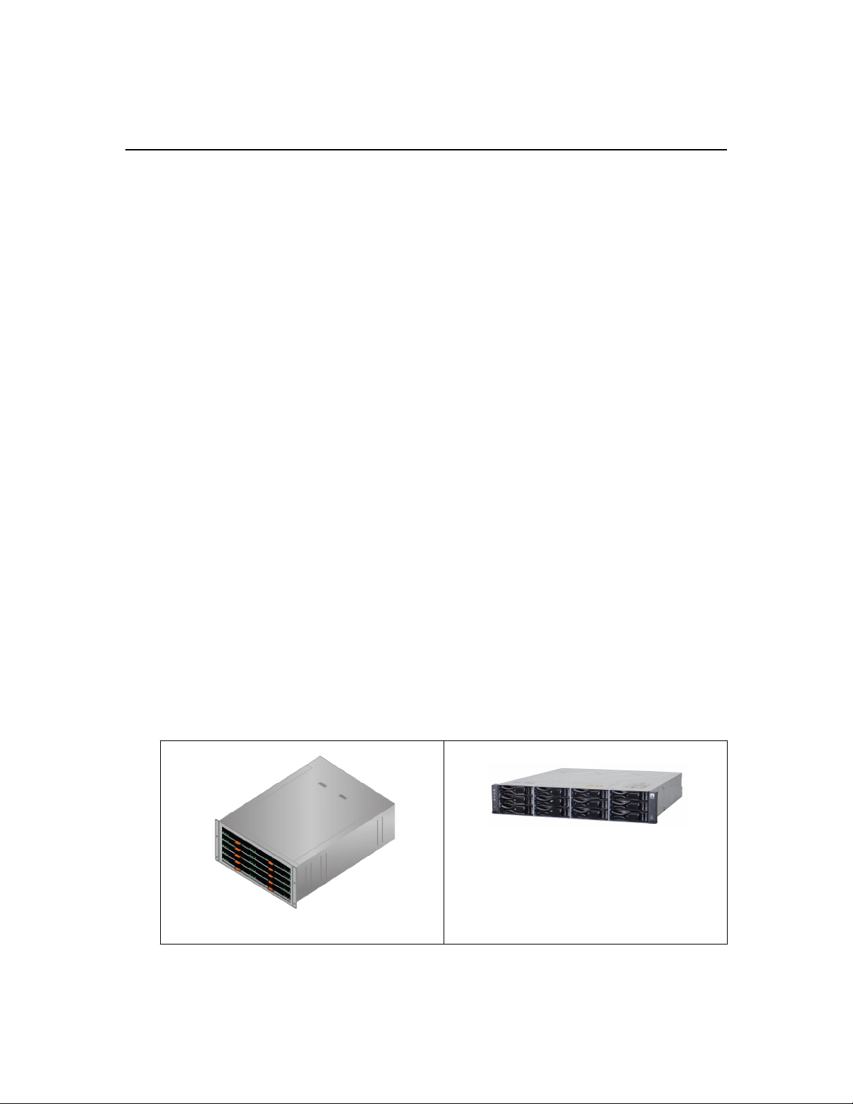
The StorageGRID Webscale appliance is an integrated storage and computing platform that operates
as a Storage Node in a StorageGRID Webscale system. Housed in a DE1600 enclosure or DE6600
enclosure, the appliance includes the E5600SG controller, the E2700 controller, drives, fans, and
power supplies.
The StorageGRID Webscale appliance includes the following components:
Component Description
E5600SG controller Compute server
The E5600SG controller runs the Linux operating system and the
StorageGRID Webscale software.
This controller connects to the following:
• The Admin, Grid, and Client networks for the StorageGRID Webscale
system
• The E2700 controller, using dual SAS paths (active/active) with the
E5600SG controller operating as the initiator
E2700 controller Storage controller
The E2700 controller operates as a standard E-Series storage array in
simplex mode, and runs the SANtricity operating system (controller
firmware).
This controller connects to the following:
• The management network where SANtricity Storage Manager software
is installed
• The E5600SG controller, using dual SAS paths (active/active) with the
E2700 controller operating as the target
The StorageGRID Webscale appliance also includes the following components, depending upon the
appliance model:
Component
Drives 12 NL-SAS drives 60 NL-SAS drives
Enclosure DE1600 enclosure, a two rack-unit
Power supplies and
fans
Model SG5612 Model SG5660
DE6600 enclosure, a four rack-unit
(2U) chassis that houses the drives
and the controllers
Two power-fan canisters Two power supplies and two fans
(4U) chassis that houses the drives
and the controllers
Note: The maximum raw storage available on each StorageGRID Webscale appliance Storage
Node is fixed, based on the appliance model and configuration. You cannot expand the available
storage by adding a shelf with additional drives.
All E-Series components operate as documented in the E-Series technical documents except as
indicated in this guide. For details, see the E-Series documentation.
Note: The E5600SG controller is highly customized for StorageGRID Webscale, so some of the E-
Series maintenance procedures might not apply (for example, the procedure for upgrading
Page 7
StorageGRID Webscale appliance overview | 7
controller firmware). For more information, see “Maintaining your StorageGRID Webscale
appliance” in this guide.
Related tasks
Maintaining your StorageGRID Webscale appliance
Related information
on page 46
NetApp Documentation: E2700 Series
NetApp Documentation: E5600 Series
StorageGRID Webscale appliance features
The StorageGRID Webscale appliance provides an integrated storage solution for creating a new
StorageGRID Webscale system or for expanding the capacity of an existing system.
The StorageGRID Webscale appliance provides the following features:
• Combines the StorageGRID Webscale Storage Node computing and storage elements into a
single, efficient, integrated solution
• Simplifies the installation and configuration of a Storage Node, automating most of the process
required
• Provides a high-density storage solution with two enclosure options: one that is 2U and one that is
4U
• Uses 10-GbE IP interfaces directly to the Storage Node, without the need for intermediate storage
interfaces such as FC or iSCSI
• Can be used in a hybrid grid environment that uses StorageGRID Webscale appliances and virtual
(software-based) Storage Nodes
• Includes preconfigured storage and comes preloaded with the StorageGRID Webscale Appliance
Installer (on the E5600SG controller) for field-ready software deployment and integration
Hardware diagrams
The SG5612 and SG5660 models of the StorageGRID Webscale appliance both include an E2700
controller and an E5600SG controller. You should review the diagrams to learn the differences
between the models and the controllers.
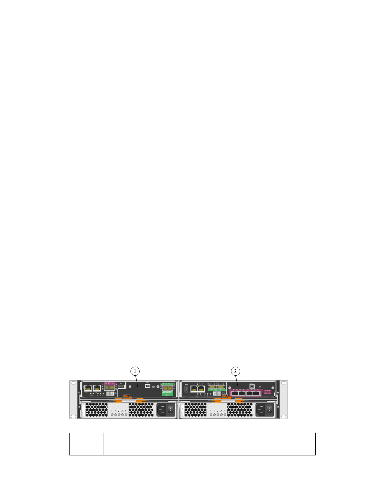
Model SG5612 2U: Rear view of the E2700 controller and E5600SG controller
1
2 E5600SG controller
E2700 controller
Page 8
| StorageGRID Webscale 10.4 Appliance Installation and Maintenance Guide
8
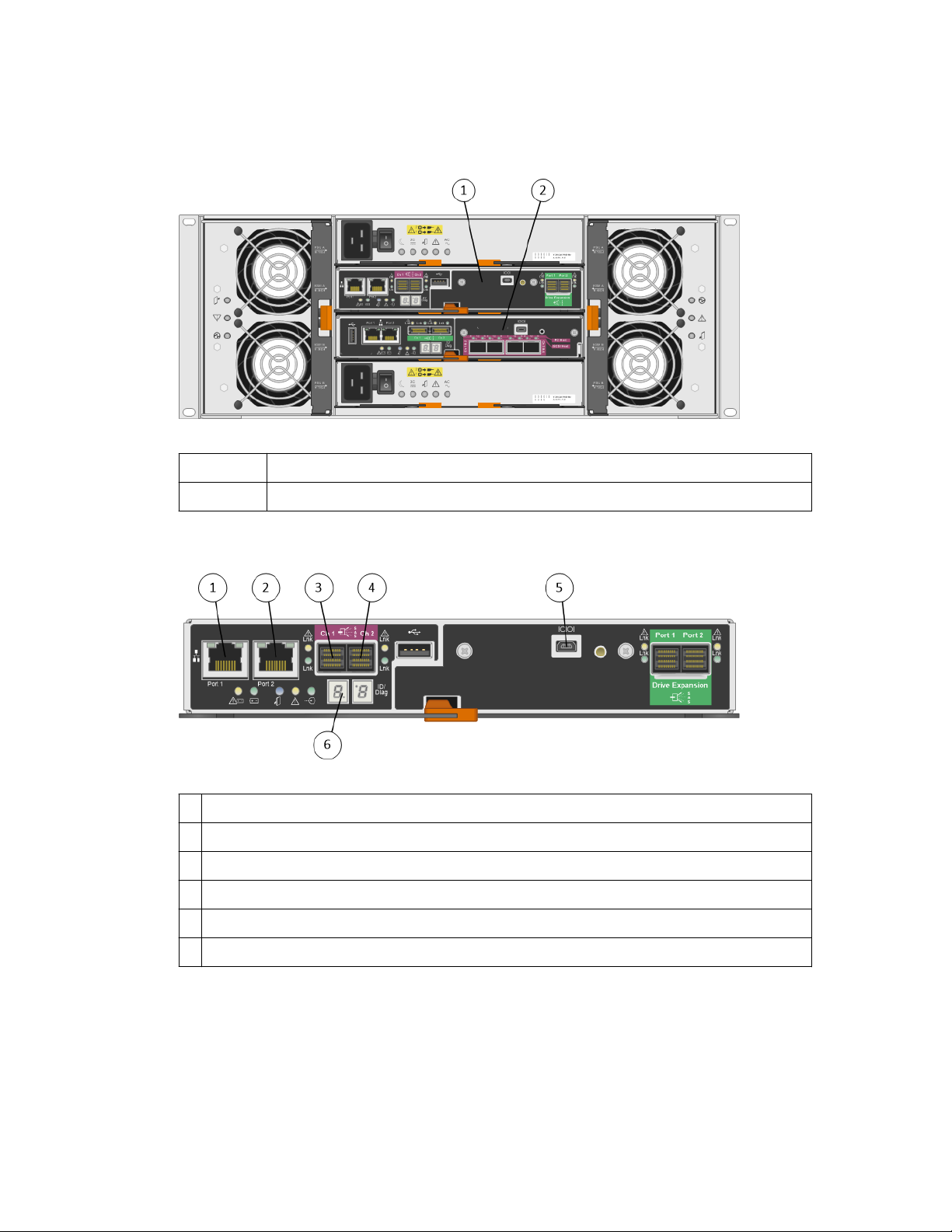
Model SG5660 4U: Rear view of the E2700 controller and E5600SG controller
The E2700 controller is above the E5600SG controller.
1
E2700 controller
2 E5600SG controller
Rear view of the E2700 controller
1
Management port 1 (connects to the network where SANtricity Storage Manager is installed)
2 Management port 2 (used during installation to connect to a laptop)
3 SAS interconnect port 1
4 SAS interconnect port 2
5 Serial connection port
6 Seven-segment display
Note: The two SAS ports labeled Drive Expansion (green) on the rear of the E2700 controller are
not used. The StorageGRID Webscale appliance does not support expansion drive shelves.
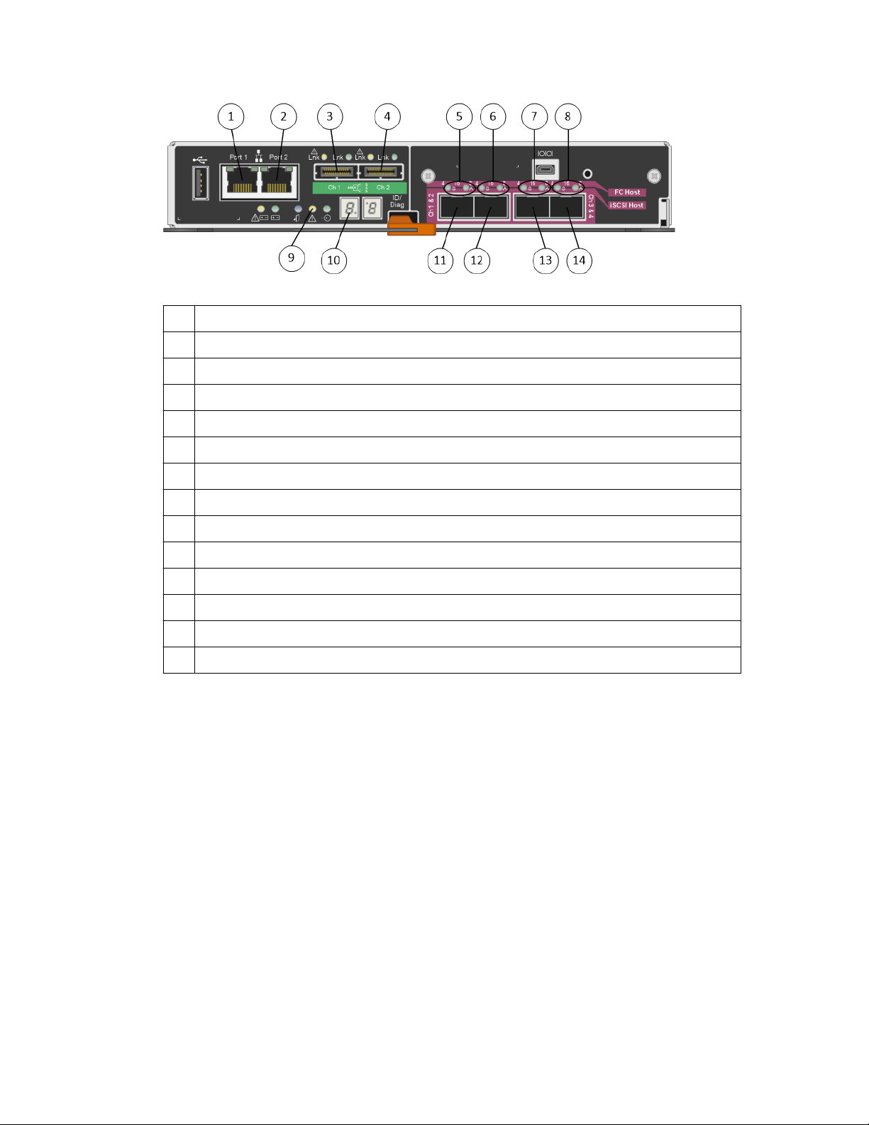
Rear view of the E5600SG controller
Page 9
StorageGRID Webscale appliance overview |
1 Management port 1 (connects to the Admin network for StorageGRID Webscale)
2 Management port 2 (used during installation to connect to a laptop)
3 SAS interconnect port 1
4 SAS interconnect port 2
5 Fault and Active LEDs for 10-GbE network port 1
6 Fault and Active LEDs for 10-GbE network port 2
9
7 Fault and Active LEDs for 10-GbE network port 3
8 Fault and Active LEDs for 10-GbE network port 4
9 Needs Attention LED
10 Seven-segment display
11 10-GbE network port 1
12 10-GbE network port 2
13 10-GbE network port 3
14 10-GbE network port 4
Note: The host interface card (HIC) on the StorageGRID Webscale appliance E5600SG controller
supports only 10-Gb Ethernet connections. It cannot be used for iSCSI connections.
Page 10
10
Planning your deployment
Planning your deployment involves checking the contents of the boxes, preparing the site, and
ensuring that your systems meet the minimum resource requirements. Using a Deployment Data
worksheet, you should also gather your site-specific deployment data.
Steps
1. Review the content of the boxes and ensure that you identify all components.
Verify that you have access to a service laptop with the installation requirements.
2.
Prepare the site for the hardware installation.
3.
Gather data for deploying the StorageGRID Webscale appliance.
4.
Related tasks
Preparing the site
Gathering data for deploying StorageGRID Webscale appliance
Related references
StorageGRID Webscale appliance components
Service laptop requirements
StorageGRID Webscale appliance connections
on page 15
on page 17
on page 10
on page 12
on page 15
StorageGRID Webscale appliance components
Before installing the StorageGRID Webscale appliance, you should verify that the appliance boxes
contain all required components and that you have additional tools required to install and manage
them.
Hardware
The StorageGRID Webscale appliance includes the following hardware components:
SG5660 enclosure, a 4U chassis with 60 drives
SG5612 enclosure, a 2U chassis with 12 drives
Page 11
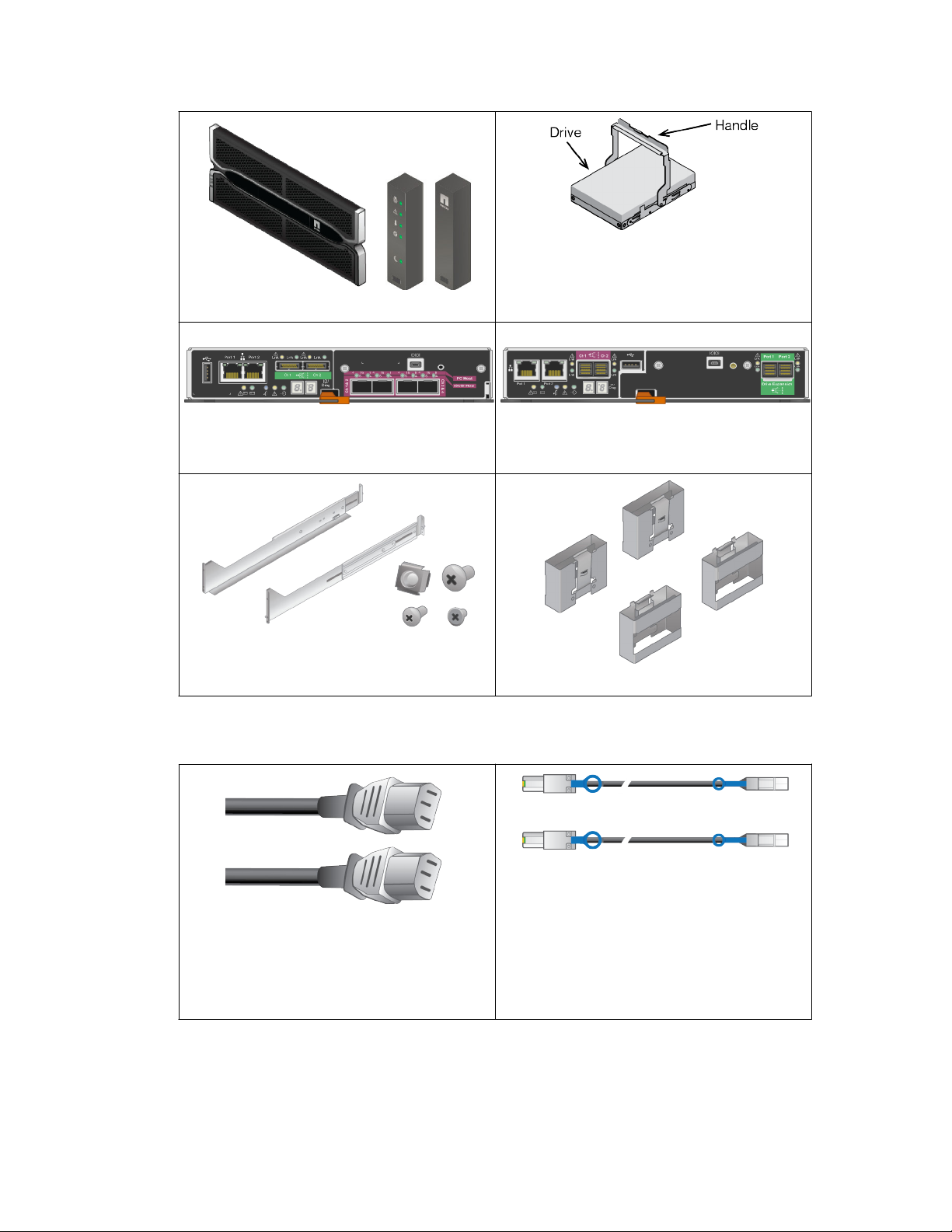
4U bezel or 2U endcaps
Planning your deployment |
NL-SAS drives. Drives are preinstalled in the
2U SG5612, but not in the 4U SG5660 for
shipment safety.
11
The E5600SG controller might need to be
installed in the enclosure.
Mounting rails and screws
Cables and connectors
The StorageGRID Webscale appliance includes the following cables and connectors:
The E2700 controller is preinstalled inside the
Enclosure handles (4U enclosures only)
enclosure.
Two 0.5-meter SAS interconnect cables with
mini-SAS-HD and mini-SAS connectors.
The square connector plugs into the E2700
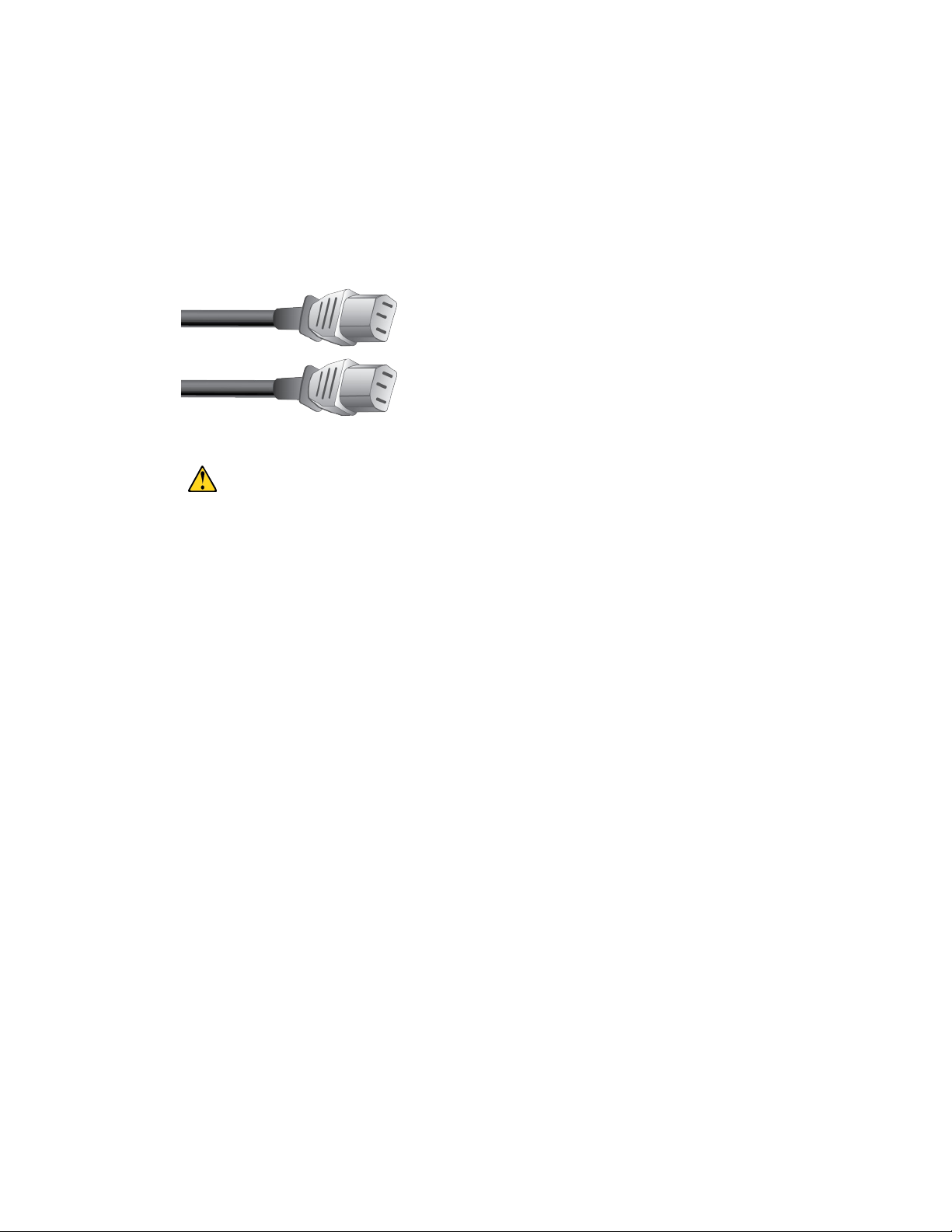
The appliance ships with two AC power cords
for connecting to an external power source, such
as a wall plug. Your cabinet might have special
power cords that you use instead of the power
cords that ship with the appliance.
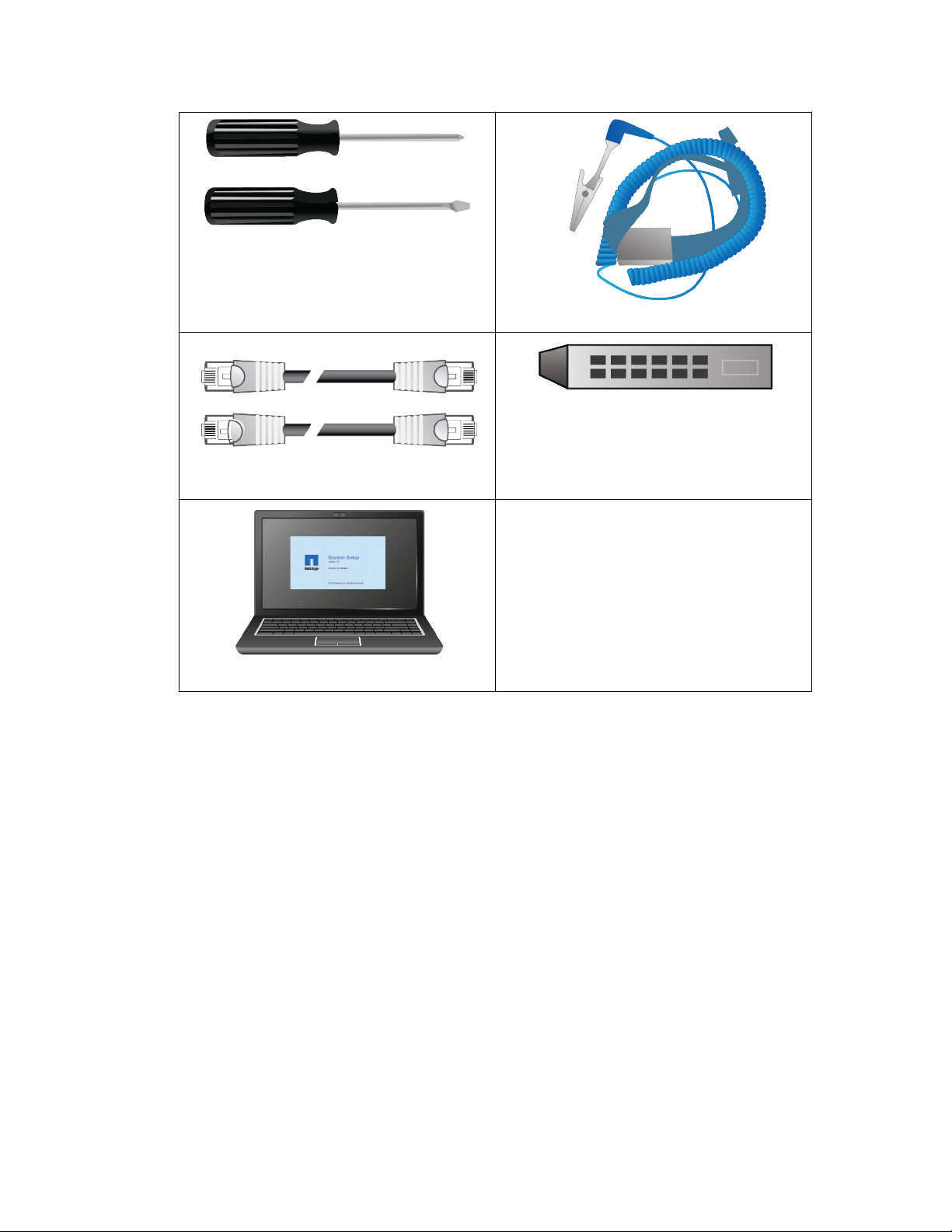
Additional equipment you need
You need the following additional equipment for management and setup:
controller, and the rectangular connector plugs
into the E5600SG controller.
Page 12
| StorageGRID Webscale 10.4 Appliance Installation and Maintenance Guide
12
Phillips No. 2 and medium flat-blade
screwdrivers
Ethernet cables
ESD wrist strap
Ethernet switch
Management station service laptop
Service laptop requirements
Before you install the StorageGRID Webscale appliance hardware, you should check to see if the
service laptop has the minimum required resources.
The service laptop, which is needed for the hardware installation, must meet the following
requirements:
• Microsoft Windows operating system
• Network port
• Supported web browser
Note: If you plan to use Internet Explorer 11, you must disable webpage caching.
• NetApp SANtricity Storage Manager version 11.30 or later
• SSH client (for example, PuTTY)
Related tasks
Disabling webpage caching in Internet Explorer 11
on page 13
Related references
Web browser requirements
on page 13
Page 13
Related information
NetApp Documentation: SANtricity Storage Manager
Web browser requirements
You must use a supported web browser.
Web browser Minimum supported version
Google Chrome 54
Microsoft Internet Explorer 11 (Native Mode)
Mozilla Firefox 50
You should set the browser window to a recommended width.
Planning your deployment |
13
Browser width
Minimum 1024
Optimum 1280
Pixels
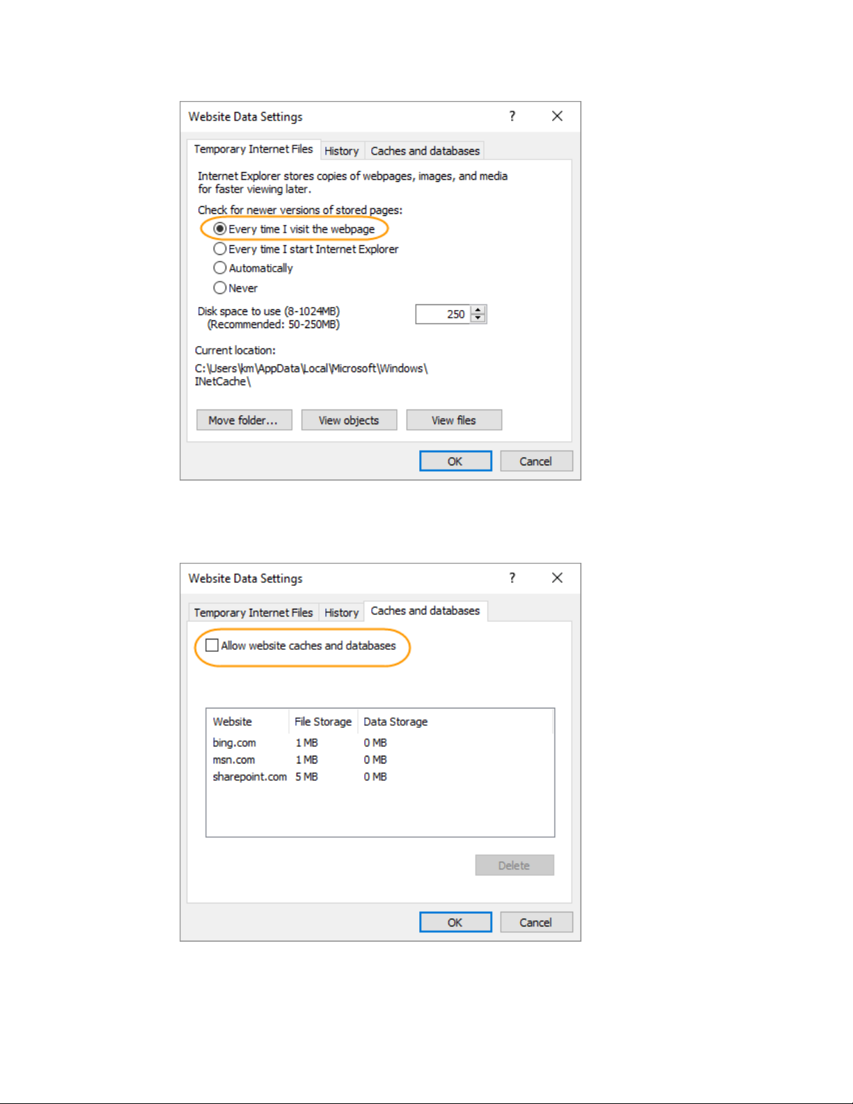
Disabling webpage caching in Internet Explorer 11
The StorageGRID Webscale Installer web page might appear to function incorrectly if you use
webpage caching in Internet Explorer 11. You must disable caching if you want to use this browser to
access the Installer web page.
Steps
1. From the top right corner of Internet Explorer 11, click the Gear icon .
2. From the menu, select Internet options.
3. On the General tab, locate the Browsing history section, and click Settings.
4. On the Temporary Internet Files tab, confirm that Every time I visit the webpage is selected.
Page 14
| StorageGRID Webscale 10.4 Appliance Installation and Maintenance Guide
14
5. On the Caches and databases tab, confirm that Allow website caches and databases is not
selected.
6. Click OK.
Page 15
Planning your deployment |
Preparing the site
Installing the controllers and drive trays into the cabinet requires some preparation.
About this task
You must do the following to prepare the site:
• Prepare the site for the cabinet and its requirements: for example, temperature, humidity, altitude
range, airflow, heat dissipation, wiring, power, and grounding.
• Prepare the network for the controllers.
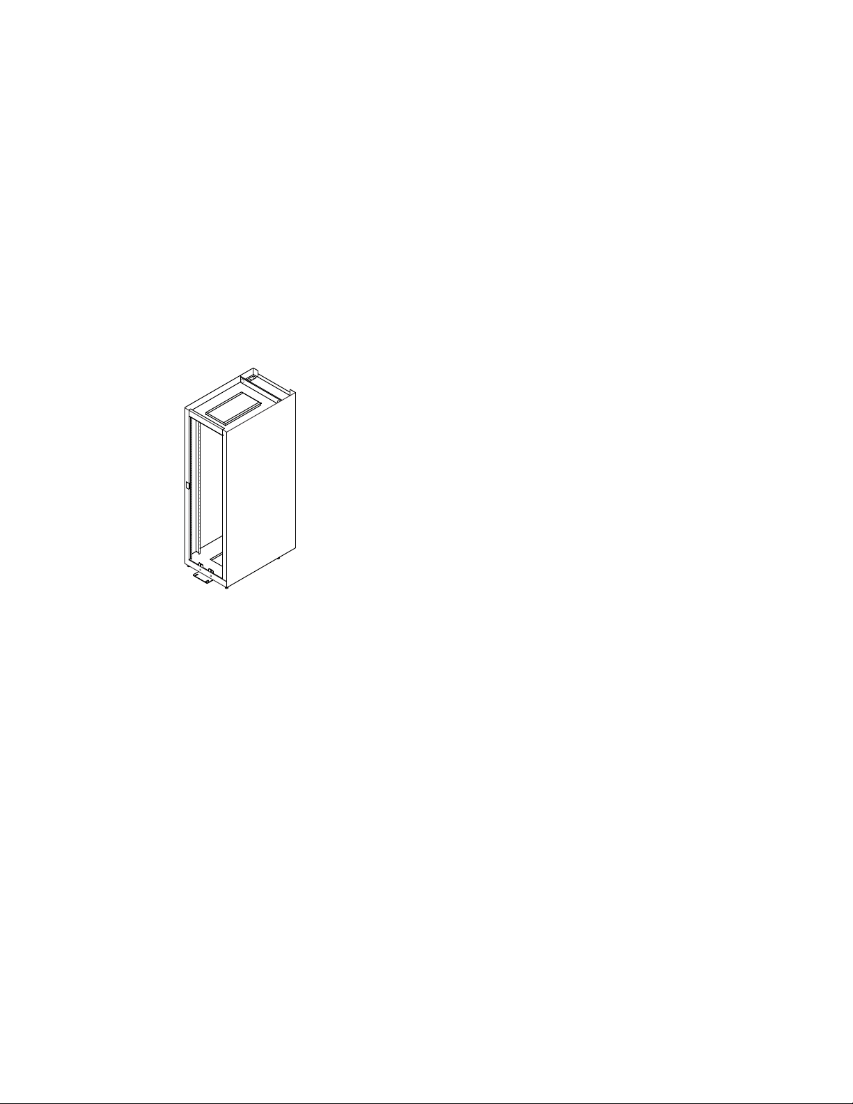
• Ensure that the cabinet in which the appliance will be mounted meets the installation site
specifications for E-Series storage arrays.
15
For details, see the
Related information
E-Series Site Preparation Guide
.
E-Series Site Preparation Guide
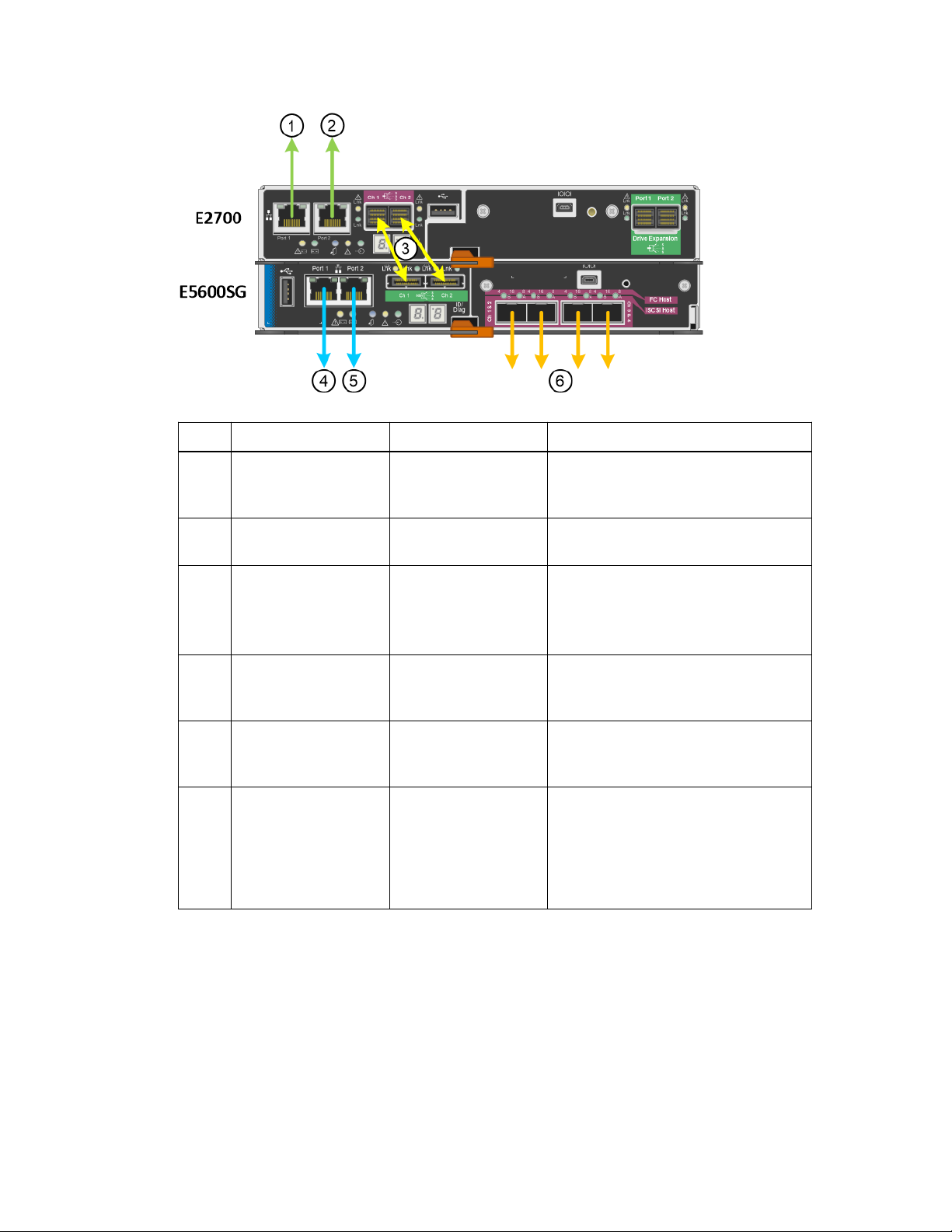
StorageGRID Webscale appliance connections
Before installing the StorageGRID Webscale appliance, make sure you understand how the controller
ports are used.
The controllers in the StorageGRID Webscale appliance include the following ports. The diagram
shows the SG5660 model; the controllers in the SG5612 model are side by side instead of stacked.
Page 16
| StorageGRID Webscale 10.4 Appliance Installation and Maintenance Guide
16
Item
1 Management port 1 on
2 Management port 2 on
3 Two SAS interconnect
4 Management port 1 on
5 Management port 2 on
6 Four network ports on
Port Type of port Function
the E2700 controller
the E2700 controller
ports on each
controller, labelled Ch
1 and Ch 2
the E5600SG
controller
the E5600SG
controller
the E5600SG
controller
1-Gb (RJ-45) Ethernet Connects the E2700 controller to the
network where SANtricity Storage
Manager is installed.
1-Gb (RJ-45) Ethernet Connects the E2700 controller to a
service laptop during installation.
E2700 controller:
mini-SAS-HD
E5600SG controller:
mini-SAS
1-Gb (RJ-45) Ethernet Connects the E5600SG controller to the
1-Gb (RJ-45) Ethernet Connects the E5600SG controller to a
10-GbE (optical) Connect the E5600SG controller to the
Connect the two controllers to each
other.
Admin network for StorageGRID
Webscale.
service laptop during installation.
Grid network and to the Client network
(if used) for StorageGRID Webscale.
The ports can be bonded together to
provide redundant paths to the
controller.
Connections for the 10-GbE ports on the E5600SG controller
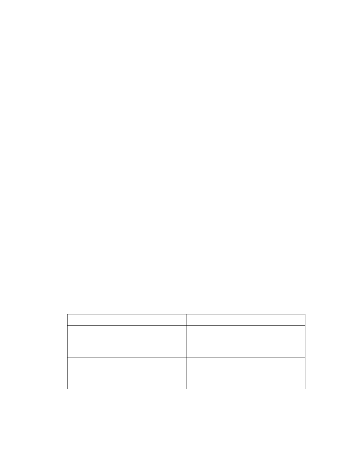
The four network ports on the E5600SG controller are bonded together to provide redundant paths to
the controller, as follows:
• Fixed Port Configuration (default) – Ports 2 and 4 control the Grid network, and ports 1 and 3
control the Client network, if enabled. The ports can be bonded in active-backup mode or in Link
Aggregation Control Protocol mode (LACP IEEE 802.3ad).
◦ In active-backup mode (default), only one port is active at a time. If the active port fails, its
backup port automatically provides a failover connection. When you use fixed port
configuration, port 4 provides a backup path for port 2 (Grid network), and port 3 provides a
backup path for port 1 (Client network).
Page 17
Planning your deployment | 17
◦ In LACP mode, each pair of ports forms a logical channel between the controller and the
network, allowing for higher throughput. If one port fails, the other port provides a failover
connection. LACP mode requires version 1.7 or later of the StorageGRID Webscale Appliance
Installer.
• Aggregate Port Configuration – Starting with version 1.7 of the StorageGRID Webscale
Appliance Installer, you can specify that all four ports be grouped in a single LACP bond,
allowing all ports to be used for Grid network and Client network traffic. Aggregate Port
Configuration significantly increases the throughout for each network and provides additional
failover paths. When using Aggregate Port Configuration, you must specify a unique VLAN ID
for each network. This VLAN ID will be added to each network packet to ensure that network
traffic is routed to the correct network.
For more information on configuring these ports, see the instructions for cabling the appliance and
the appropriate
Related tasks
StorageGRID Webscale Software Installation Guide
.
Gathering data for deploying StorageGRID Webscale appliance
Cabling the appliance
Related information
on page 23
on page 17
StorageGRID Webscale 10.4 Software Installation Guide for VMware Deployments
StorageGRID Webscale 10.4 Software Installation Guide for OpenStack Deployments
StorageGRID Webscale 10.4 Software Installation Guide for Red Hat Enterprise Linux
Deployments
Gathering data for deploying StorageGRID Webscale appliance
Before deploying the StorageGRID Webscale appliance, you must gather information about Ethernet
switch ports and IP addresses.
About this task
Refer to
to collect the information from your administrator.
StorageGRID Webscale appliance connections
Information needed
Specify the Ethernet switch port you will
connect to management port 1 on the E2700
controller (used to access the management
network for SANtricity Storage Manager)
on page 15, and use the following worksheet
Your value
Switch port for management port 1 on E2700
controller:
Specify the Ethernet switch port you will
connect to management port 1 on the E5600SG
controller (used to access the Admin network
for StorageGRID Webscale)
Switch port for management port 1 on
E5600SG controller:
Page 18

| StorageGRID Webscale 10.4 Appliance Installation and Maintenance Guide
18
Information needed Your value
MAC addresses or IP addresses for management
ports
• If the management network (or networks)
includes a DHCP server, enter the MAC
address from the labels next to management
port 1 on the back of each controller. The
network administrator can use the MAC
address to determine what IP address was
assigned by the DHCP server. (For some
E5600SG controllers, the DHCP-assigned IP
address is displayed on the seven-segment
display after you apply power.)
• If you do not use DHCP, enter the static IP
address that you plan to use for these ports
on your network.
Specify the switch ports you will connect to the
four 10-GbE optical ports on the E5600SG
controller.
Note: If you plan to use Fixed Port
Configuration, ports 2 and 4 connect to the
Grid network for StorageGRID Webscale,
and ports 1 and 3 connect to the Client
network for StorageGRID Webscale. If you
plan to use Aggregate Port Configuration, see
information about StorageGRID Webscale
appliance connections and cabling the
appliance.
Address for management port 1 on E2700
controller:
Address for management port 1 on E5600SG
controller:
Switch port for Port 2:
Switch port for Port 4:
Switch port for Port 1:
Switch port for Port 3:
Specify the IP address of the Grid network
interface for StorageGRID Webscale.
Note: This information might not be
available at the time you are performing the
hardware phase of the installation.
Specify the IP address of the Client network
interface for StorageGRID Webscale.
Note: This information might not be
available at the time you are performing the
hardware phase of the installation.
Related tasks
Cabling the appliance
Related references
on page 23
StorageGRID Webscale appliance connections
Grid network IP address:
Client network IP address:
on page 15
Page 19

Installation overview
Typically, installation is performed in two phases: the hardware installation in the data center and,
later, the software installation.
Hardware installation
The hardware installation occurs before the software installation, even months before, and someone
other than the software installer can perform it. Installation of the physical components requires the
following:
• Physical access to the StorageGRID Webscale appliance hardware
• Knowledge of the IP address for the network where SANtricity Storage Manager is installed
• Knowledge of the IP address for the Admin network for StorageGRID Webscale
Software installation
The software installation occurs after the hardware installation. Installation of the software requires
knowledge about the following:
19
• StorageGRID Webscale software
• Grid network IP addresses
• Client network IP addresses, if used
For details, see StorageGRID Webscale software installation instructions.
Related information
StorageGRID Webscale 10.4 Software Installation Guide for VMware Deployments
StorageGRID Webscale 10.4 Software Installation Guide for OpenStack Deployments
StorageGRID Webscale 10.4 Software Installation Guide for Red Hat Enterprise Linux
Deployments
Page 20

20
Installing the appliance hardware
Hardware installation includes several major tasks, including installing hardware components,
cabling those components, and configuring ports.
Steps
1. Registering the hardware on page 20
2. Installing the hardware on page 21
3. Installing the E5600SG controller in the enclosure on page 22
4. Cabling the appliance on page 23
5. Connecting the AC power cords on page 25
6. Turning power on on page 26
7. Viewing boot-up status and reviewing error codes on the controllers on page 27
8. Configuring the management ports on page 30
9. Verifying connectivity on page 36
10. Configuring the AutoSupport tool for the StorageGRID Webscale appliance on page 37
11. Changing the RAID volume configuration settings on page 39
Registering the hardware
Registering the hardware provides support benefits.
Steps
1. Go to the NetApp Support Site at
2. Log in to your existing NetApp Support Site account or create an account.
• If you already have a registered account, you can log in to it and add the StorageGRID
Webscale appliance to your existing account.
• If you are a new customer, click Register Now, located at the top of the Support Site.
3. Select Products > Register Products.
A product registration page opens.
4. Enter the product serial number, and click Submit.
You can find the serial number on the packing slip, in your confirmation email, or on the
appliance itself.
mysupport.netapp.com
.
5. On the product details page, enter the requested details, and click Submit to complete your
product registration.
Page 21
Installing the appliance hardware | 21
Installing the hardware
Installing the hardware involves installing the mounting rails, enclosure, and, for the SG5660, the
drives.
Before you begin
Installation of the StorageGRID Webscale appliance hardware is similar to the installation of the
E2700 and E5600 E-Series storage systems.
You have the following documents:
•
NetApp E-Series Storage Systems E2700 Controller-Drive Tray and Related Drive Trays
Installation Guide
•
NetApp E-Series Storage Systems E5600 Controller-Drive Tray and Related Drive Trays
Installation Guide
About this task
Warning: Risk of electrical shock - Before removing or installing a power supply, turn
off the power switch and unplug the power cord.
Warning: Risk of bodily injury - Each tray has more than one power cord. To remove all
electrical current from the devices, make sure that all of the power cords are disconnected
from the power source.
Warning: Risk of bodily injury - Do not use equipment in the cabinet as a shelf or work
space.
Warning: Risk of exposure to laser radiation - Do not disassemble or remove any part
of an SFP transceiver because you might be exposed to laser radiation.
The following warning applies to the SG5612 only.
Warning: Risk of bodily injury - Two people or a mechanical lift are required to lift the
component safely.
The following warning applies to the SG5660 only.
Warning: Risk of bodily injury - Four people or a mechanical lift are required to lift the
component safely.
Attention: Risk of equipment damage – If you want to move the SG5660 to a new
location, you must remove all of the drives from the enclosure. Never move or ship the
SG5660 with drives installed.
For additional warnings, refer to the printed Safety Notices document.
Task
Description
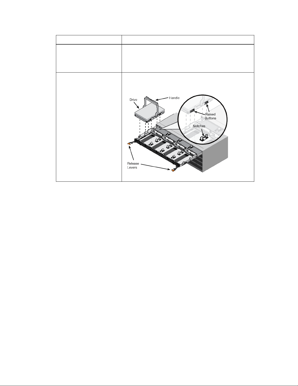
Install the mounting rails Install the mounting rails into the cabinet.
Page 22
| StorageGRID Webscale 10.4 Appliance Installation and Maintenance Guide
22
Task Description
Install enclosure in rack Install the DE1600 enclosure or DE6600 enclosure in the rack.
If you are lifting the DE6600 enclosure by hand, attach the four
enclosure handles for easier lifting. You can remove these
handles later.
Install drives in drive drawer For the SG5660 model, install the drives in the DE6600
enclosure drive drawer.
Related information
E2700 Controller-Drive Tray and Related Drive Trays Installation Guide
E5600 Controller-Drive Tray and Related Drive Trays Installation Guide
Installing the E5600SG controller in the enclosure
If the E5600SG controller is not installed when you receive the enclosure, you might need to install it
into Slot B.
About this task
You can skip this procedure if the E5600SG controller is already installed in the enclosure.
Steps
1. Remove the insert that was placed in Slot B for shipment.
In the SG5660 enclosure, Slot B is the bottom slot. In the SG5612 enclosure, Slot B is the slot on
the right.
2. Install the E5600SG controller into Slot B.
After you finish
Continue with cabling the appliance.
Page 23
Installing the appliance hardware | 23
Cabling the appliance
You must connect the two controllers to each other with SAS interconnect cables, connect the
management ports to the appropriate management network, and connect the 10 GbE ports on the
E5600SG controller to the Grid network and optional Client network for StorageGRID Webscale.
About this task
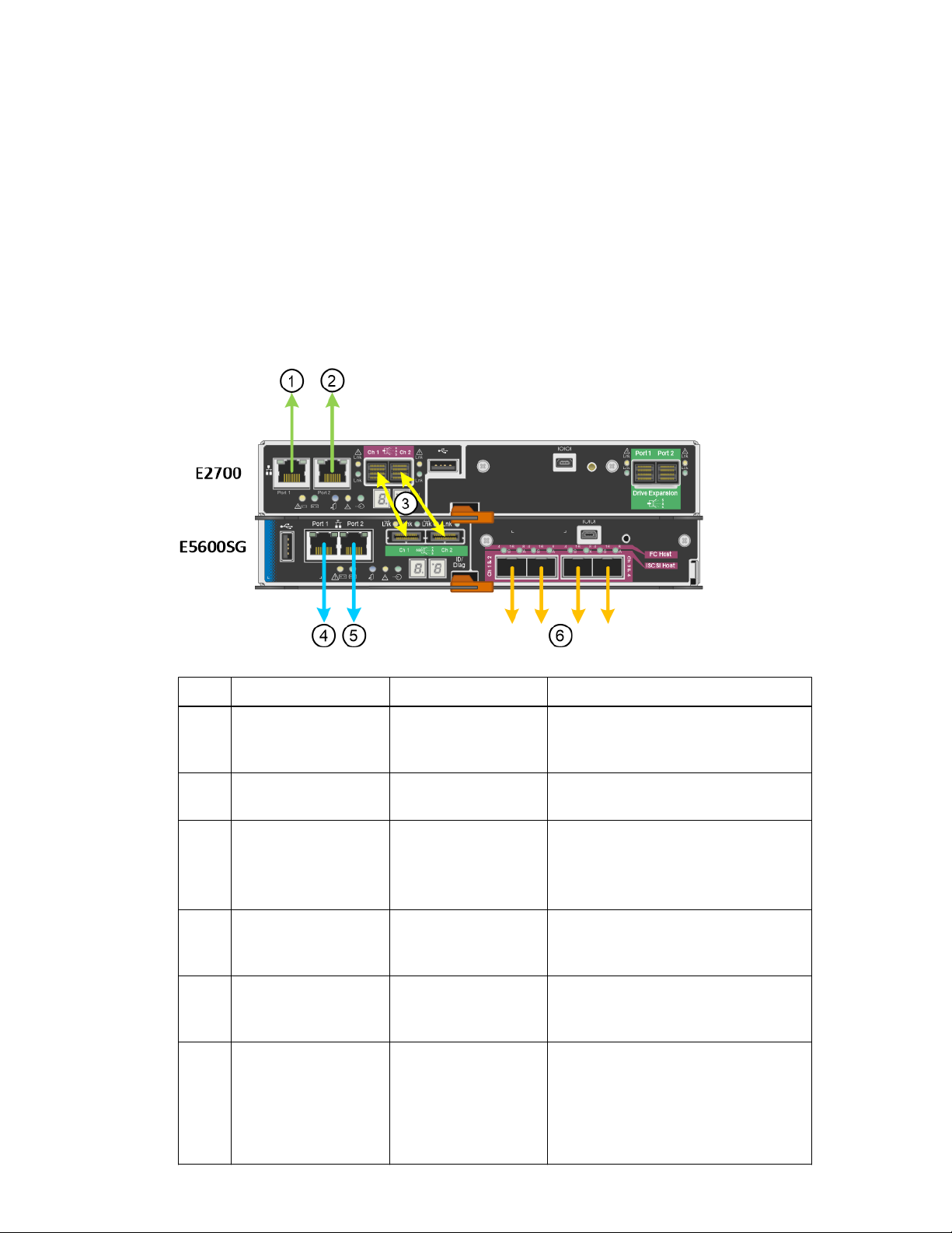
When connecting the cables, refer to the following diagram, which shows the E2700 controller on the
top and the E5600SG controller on the bottom. The diagram shows the SG5660 model; the
controllers in the SG5612 model are side by side instead of stacked.
Item
1 Management port 1 on
2 Management port 2 on
3 Two SAS interconnect
4 Management port 1 on
5 Management port 2 on
6 Four network ports on
Port Type of port Function
the E2700 controller
the E2700 controller
ports on each
controller, labelled Ch
1 and Ch 2
the E5600SG
controller
the E5600SG
controller
the E5600SG
controller
1-Gb (RJ-45) Ethernet Connects the E2700 controller to the
network where SANtricity Storage
Manager is installed.
1-Gb (RJ-45) Ethernet Connects the E2700 controller to a
service laptop during installation.
E2700 controller:
mini-SAS-HD
E5600SG controller:
mini-SAS
1-Gb (RJ-45) Ethernet Connects the E5600SG controller to the
1-Gb (RJ-45) Ethernet Connects the E5600SG controller to a
10-GbE (optical) Connect the E5600SG controller to the
Connect the two controllers to each
other.
Admin network for StorageGRID
Webscale.
service laptop during installation.
Grid network and to the Client network
(if used) for StorageGRID Webscale.
The ports can be bonded together to
provide redundant paths to the
controller.
Page 24
| StorageGRID Webscale 10.4 Appliance Installation and Maintenance Guide
24
When connecting the 10-GbE network ports on the E5600SG controller, note that version 1.7 and
later of the StorageGRID Webscale Appliance Installer supports two configurations for these ports,
as follows:
• In the Fixed Port Configuration, ports 2 and 4 are bonded together for the Grid network, and
ports 1 and 3 are bonded together for the Client network, if used. The ports can be bonded using
active-backup mode or Link Aggregation Control Protocol mode (LACP IEEE 802.3ad).
• In the optional Aggregated Port Configuration, all four ports are grouped together in a single
LACP bond, and all ports are used for both Grid network and Client network traffic. If you plan to
use Aggregated Port Configuration:
◦ You must be using version 1.7 or later of the StorageGRID Webscale Appliance Installer.
Note: You cannot determine which version of the StorageGRID Webscale Appliance
Installer is included with the appliance until you configure the E5600SG controller
management port. If you discover that you need to upgrade the StorageGRID
WebscaleAppliance Installer to version 1.7, you must contact technical support.
◦ The ports must be connected to switches that can support VLAN, LACP, or multi-chassis link
aggregation groups (MLAG), or equivalent, if multiple switches are participating in the LACP
bond.
◦ You must understand how to configure the switches to use VLAN, LACP, or MLAG, or
equivalent, if multiple switches are participating in the LACP bond.
For more information, see the appropriate
Steps
StorageGRID Webscale Installation Guide
.
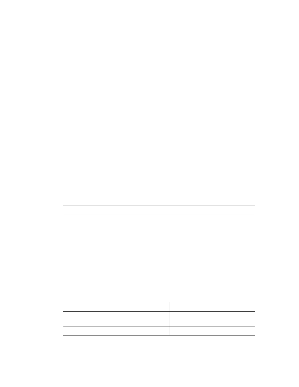
1. Connect the E2700 controller to the E5600SG controller, using the two SAS interconnect cables.
Connect this port...
SAS interconnect port 1 (labeled Ch 1) on the
E2700 controller
SAS interconnect port 2 (labeled Ch 2) on the
E2700 controller
To this port...
SAS interconnect port 1 (labeled Ch 1) on the
E5600SG controller
SAS interconnect port 2 (labeled Ch 2) on the
E5600SG controller
Use the square connector (mini-SAS HD) for the E2700 controller, and use the rectangular
connector (mini-SAS) for the E5600SG controller.
Attention: Make sure the pull tabs on the SAS connectors are at the bottom, and carefully
insert each connector until it clicks into place. Do not push on the connector if there is any
resistance. Verify the position of the pull tab before continuing.
2. Connect the E2700 controller to the management network where SANtricity Storage Manager
software is installed, using an Ethernet cable.
Connect this port...
Port 1 on the E2700 controller (the RJ-45 port on
the left)
To this port...
Switch port on the management network
used for SANtricity Storage Manager
Port 2 on the E2700 controller Service laptop, if not using DHCP
3. Connect the E5600SG controller to the Admin network for StorageGRID Webscale, using an
Ethernet cable.
Page 25
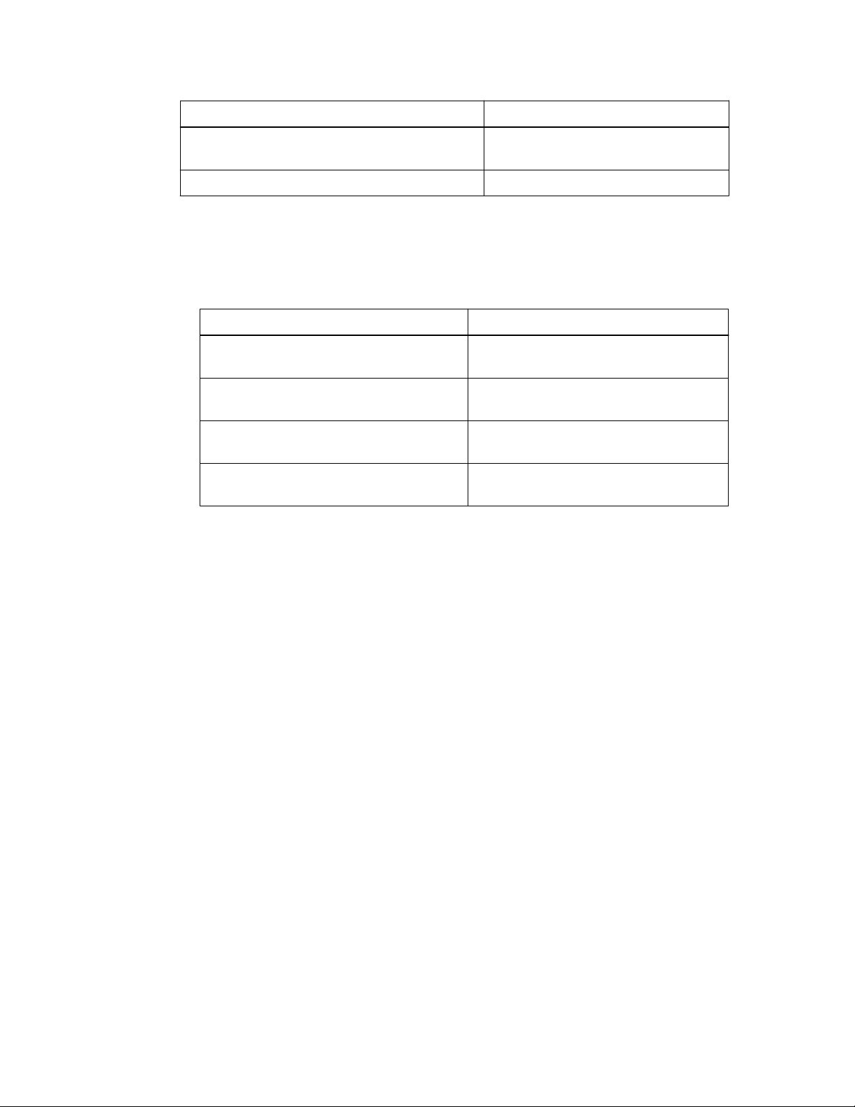
Installing the appliance hardware |
Connect this port... To this port...
25
Port 1 on the E5600SG controller (the RJ-45 port
on the left)
Port 2 on the E5600SG controller Service laptop, if not using DHCP
4. Using 10-GbE optical cables and SFP transceivers as required, connect the 10-GbE optical ports
on the E5600SG controller to the appropriate switch ports.
• If you plan to use the Fixed Port Configuration, or if the E5600SG controller includes version
1.6 or earlier of the StorageGRID Webscale Appliance Installer, connect the ports as shown in
the table.
Connect this port....
E5600SG controller Port 1 Switch port on Client network for
E5600SG controller Port 2 Switch port on Grid network for
E5600SG controller Port 3 Switch port on Client network for
E5600SG controller Port 4 Switch port on Grid network for
If you have version 1.7 or later of the StorageGRID Webscale Appliance Installer, you can
specify how the ports should be bonded (either active-backup mode or LACP (802.3ad) mode)
when you configure the appliance. You can also optionally specify VLAN IDs for each
network.
Switch port on the Admin network for
StorageGRID Webscale
To this port...
StorageGRID Webscale (optional)
StorageGRID Webscale
StorageGRID Webscale (optional)
StorageGRID Webscale
• If you plan to use the Aggregate Port Configuration, connect all four ports to one or more
switches. When you configure the appliance with the StorageGRID Webscale Appliance
Installer, you must specify VLAN IDs for the Grid network and the Client network. See your
switch documentation for more instructions.
Warning: Risk of exposure to laser radiation – Do not disassemble or remove any part of an
SFP transceiver because you might be exposed to laser radiation.
Related tasks
Configuring the E5600SG controller management port
Related information
on page 34
StorageGRID Webscale 10.4 Software Installation Guide for VMware Deployments
StorageGRID Webscale 10.4 Software Installation Guide for OpenStack Deployments
StorageGRID Webscale 10.4 Software Installation Guide for Red Hat Enterprise Linux
Deployments
Connecting the AC power cords
You must connect the AC power cords to the external power source and to the AC power connector
on each controller. After you have connected the power cords, you can turn the power on.
About this task
Consider the following power source issues:
Page 26
| StorageGRID Webscale 10.4 Appliance Installation and Maintenance Guide
26
• You should use separate power sources for each power supply.
Connecting to independent power sources maintains power redundancy.
• You can use the power cords shipped with the controller with typical outlets used in the
destination country, such as wall receptacles of an uninterrupted power supply (UPS).
However, these power cords are not intended for use in most EIA-compliant cabinets.
The following illustration shows the power cords:
Warning: Risk of bodily injury. To remove all electrical current from the devices, make
sure that all of the power cords are disconnected from the power source.
Steps
1. Turn off the power switches in the enclosure or chassis.
2. Turn off the power switches on the controllers.
3. Connect the primary power cords from the cabinet to the external power sources.
4. Connect the power cords to the AC power connector on each controller.
Turning power on
Powering on the enclosure provides power to both controllers.
Steps
1. Turn on the two power supply switches at the rear of the enclosure.
While the power is being applied, the LEDs on the controllers go on and off intermittently.
The power-on process can take up to ten minutes to complete. The controllers reboot several
times during the initial startup sequence, which causes the fans to ramp up and down and the
LEDs to flash.
2. Check the Power LED and the Host Link Active LEDs on each controller to verify that the power
was turned on.
3. Wait for all drives to show a persistent green LED, indicating that they have come online.
4. Check for green LEDs on the front and rear of the enclosure.
If you see any amber LEDs, make a note of their locations.
5. Look at the seven-segment display for the E5600SG controller.
Page 27

Installing the appliance hardware |
• If version 1.6 or later of the StorageGRID Webscale Appliance Installer is included with the
controller, this display shows HO, followed by a repeating sequence of two digits.
HO -- IP address for Admin network -- IP address for Grid network
HO
In the sequence, the first set of numbers is the DHCP-assigned IP address for the controller's
management port 1. This address is used to connect the controller to the Admin network for
StorageGRID Webscale. The second set of numbers is the DHCP-assigned IP address used to
connect the appliance to the Grid network for StorageGRID Webscale.
Note: If an IP address could not be assigned using DHCP, 0.0.0.0 is displayed.
• If version 1.3 of the StorageGRID Webscale Appliance Installer is included with the
controller, this display shows IM.
Note: DHCP IP addresses are not supported by version 1.3 of the StorageGRID Webscale
Appliance Installer.
Viewing boot-up status and reviewing error codes on the
27
controllers
The seven-segment display on each controller shows status and error codes when the appliance
powers up, while the hardware is initializing, and when the hardware fails and must back out of the
initialization. If you are monitoring the progress or troubleshooting, you should watch the sequence
of the codes as they appear.
About this task
The status and error codes for the E5600SG controller are not the same as those for the E2700
controller.
Steps
1. During boot-up, view the codes shown on the seven-segment displays to monitor progress.
2. To review error codes for the E5600SG controller, see the seven-segment display status and error
code information.
3. To review error codes for the E2700 controller, see the E2700 controller documentation on the
Support Site.
Related references
E5600SG controller seven-segment display codes
on page 27
Related information
NetApp Documentation: E2700 Series
E5600SG controller seven-segment display codes
The seven-segment display on the E5600SG controller shows status and error codes while the
appliance powers up and while the hardware is initializing. You can use these codes to determine
status and troubleshoot errors.
When reviewing status and error codes on the E5600SG controller, you should look at the following
types of codes:
Page 28
| StorageGRID Webscale 10.4 Appliance Installation and Maintenance Guide
28
General boot-up codes
Represent the standard boot-up events.
Normal boot-up codes
Represent the normal boot-up events that occur in the appliance.
Error codes
Indicate issues during the boot-up events.
The codes that appear differ depending on the installation version. You can determine the installation
version by referring to
44.
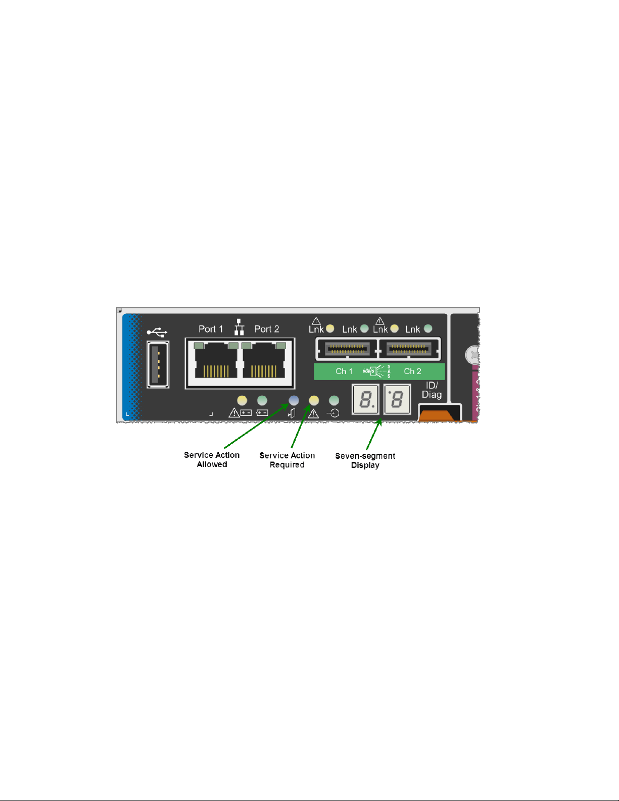
StorageGRID Webscale controls only the following LEDs on the E5600SG controller and only after
the StorageGRID Webscale Appliance Installer has started:
• Service Action Allowed LED
• Service Action Required LED
• Seven-segment display
Determining the StorageGRID Webscale Appliance Installer version
on page
The decimal points on the seven-segment display are not used by the StorageGRID Webscale
appliance:
• The upper decimal point adjacent to the least significant digit is the platform diagnostic LED.
This is turned on during reset and initial hardware configuration. Otherwise, it is turned off.
• The lower decimal point adjacent to the most significant digit is turned off.
To diagnose other issues, you might want to look at these resources:
• To see all other hardware and environmental diagnostic information, see the E-Series operating
system hardware diagnostics.
This includes looking for hardware issues such as power, temperature, and disk drives. The
appliance relies on the E-Series operating system to monitor all platform environmental statuses.
• To determine firmware and driver issues, look at the link lights on the SAS and network ports.
For details, see the E-Series E5600 documentation.
General boot-up codes
During boot-up or after a hard reset of the hardware, the Service Action Allowed and the Service
Action Required LEDs come on while the hardware is initializing. The seven-segment display shows
a sequence of codes that are the same for E-Series hardware and not specific to the E5600SG
controller.
Page 29
Installing the appliance hardware |
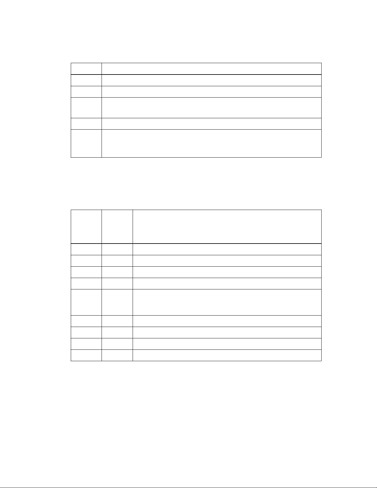
During boot-up, the Field Programmable Gate Array (FPGA) controls the functions and initialization
on the hardware.
Code Indication
19 FPGA initialization.
68 FPGA initialization.
... FPGA initialization.
This is a quick succession of codes.
AA Platform BIOS booting.
FF Bios boot-up complete.
This is an intermediate state before E5600SG controller initializes and manages LEDs
to indicate status.
After the AA and FF codes appear, either the normal boot-up codes appear or error codes appear.
Additionally, the Service Action Allowed and the Service Action Required LEDs are turned off.
Normal boot-up codes
These codes represent the normal boot-up events that occur in the appliance, in chronological order.
29
Code, if
version is
1.4 or
earlier
MB HI The master boot script has started.
PP PP The platform FPGA firmware is checking for updates.
HP HP The host interface card (HIC) is checking for updates.
RB RB After firmware updates, the system is rebooting, if necessary.
FP FP The firmware update checks have been completed. Starting the process
SE HE The system is synchronizing with the E-Series operating system.
SI HC The StorageGRID Webscale installation is being checked.
IM HO Installation management and active interfacing are occurring.
SG HA The Linux operating system and StorageGRID Webscale are running.
Error codes
These codes represent error conditions that might be shown on the E5600SG controller as the
appliance boots up. Additional two-digit hexadecimal codes are displayed if specific low-level
hardware errors occur. If any of these codes persists for more than a second or two, or if you are
unable to resolve the error by following one of the prescribed troubleshooting procedures, contact
technical support.
Code, if
version is
1.5 or
later
Indication
(utmagent) to communicate with and manage the E2700 controller. This
process facilitates appliance provisioning.
Page 30

| StorageGRID Webscale 10.4 Appliance Installation and Maintenance Guide
30
Code, if
version is
1.4 or
earlier
22 22 No master boot record found on any boot device.
23 23 No SATA drive installed.
2A, 2B 2A, 2B Stuck bus, unable to read DIMM SPD data.
40 40 Invalid DIMMs.
41 41 Invalid DIMMs.
42 42 Memory test failed.
51 51 SPD reading failure.
92 to 96 92 to 96 PCI bus initialization.
A0 to A3 A0 to A3 SATA drive initialization.
AB AB Alternate boot code.
AE AE Booting OS.
EA EA DDR3 training failed.
E8 E8 No memory installed.
Code, if
version is
1.5 or
later
Indication
EI EU The installation script was not found.
EM EP "ManageSGA" code indicates that pregrid communication with the
E2700 controller failed.
Related references
Troubleshooting the hardware installation
Related information
on page 41
E5600 Controller-Drive Tray and Related Drive Trays Installation Guide
NetApp Support
Configuring the management ports
As part of the hardware installation process, you must configure the management ports on both
controllers.
About this task
Configuring management ports includes these major tasks:
• Adding the storage array to SANtricity Storage Manager, using the IP address of the E2700
controller
• Manually configuring the E2700 controller using SANtricity Storage Manager
• Verifying initial connectivity
• Configuring the E5600SG controller using the StorageGRID Webscale Appliance Installer web
page, which is included with the controller
Page 31

Installing the appliance hardware |
Adding a storage array to SANtricity Storage Manager
You must add the StorageGRID Webscale appliance to SANtricity Storage Manager using the IP
address of the E2700 controller. You can then use SANtricity Storage Manager to manage the
hardware components and the controller firmware.
Before you begin
• If management port 1 on the E2700 controller controller is connected to a network with a DHCP
server, you have obtained the dynamically assigned IP address for the controller. (Your network
administrator can use the controller's MAC address to look up the IP address. The MAC address
is printed on a label on the back of the controller near the management port.)
Note: If you do not have a DHCP server or you are unable to obtain this address, you can set
the IP address manually, as described.
• You have a service laptop with SANtricity Storage Manager already installed.
About this task
For detailed instructions, see the SANtricity Storage Manager documentation.
31
Steps
1. Access the E2700 controller with the service laptop.
Option Description
Have DHCP-assigned IP
address
Do not have DHCP-assigned
address
Make sure the service laptop and the E2700 controller are on the same
subnet.
a. Configure the service laptop IP address with
192.168.129.1/24
b. Connect the service laptop to E2700 controller management Port 2
using an Ethernet patch cord.
2. On the service laptop, open the SANtricity Storage Manager client.
3. In SANtricity Storage Manager, in the Select Addition Method page, select Manual, and click
OK.
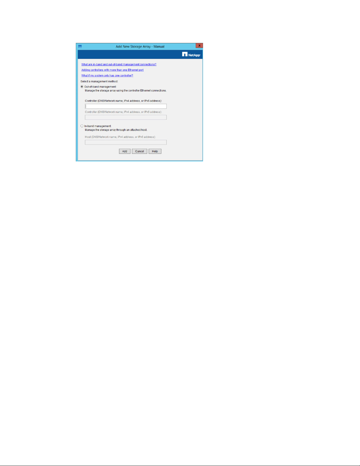
4. Select Edit > Add Storage Array.
The Add New Storage Array - Manual page appears.
Page 32
| StorageGRID Webscale 10.4 Appliance Installation and Maintenance Guide
32
In the Out-of-band management box , enter one of the following values:
5.
• Using DHCP: The IP address assigned by the DHCP server to management port 1 on the
E2700 controller
• Not using DHCP: 192.168.129.101
Note: Because you are currently configuring only the E2700 controller, enter only one
controller IP address.
6. Click Add.
7. Continue with configuring the management ports.
Related information
NetApp Documentation: SANtricity Storage Manager
Configuring the E2700 controller management port
You can use SANtricity Storage Manager on the service laptop to set the IP address for the E2700
controller management port. If you accessed the E2700 controller using an IP address obtained using
DHCP, you must follow these steps to set a static IP address.
Before you begin
You must have a service laptop with SANtricity Storage Manager already installed.
About this task
For detailed instructions, see the SANtricity Storage Manager documentation.
Attention: To ensure that you do not lose your management connection to the hardware and the
controller firmware in the StorageGRID Webscale appliance, NetApp strongly recommends that
you set a static IP address for E2700 controller by following the steps in this section.
Steps
1. From SANtricity Storage Manager, click the Devices tab.
2. In the Devices tab, double-click the newly added array.
Page 33
Installing the appliance hardware |
3. Click the Hardware tab.
4. In the Hardware pane of the Array Management Window, highlight Controller A, Port 1.
5. On the Array Management Window, from the Hardware menu, select Controller > Configure >
Configure Management Ports:
33
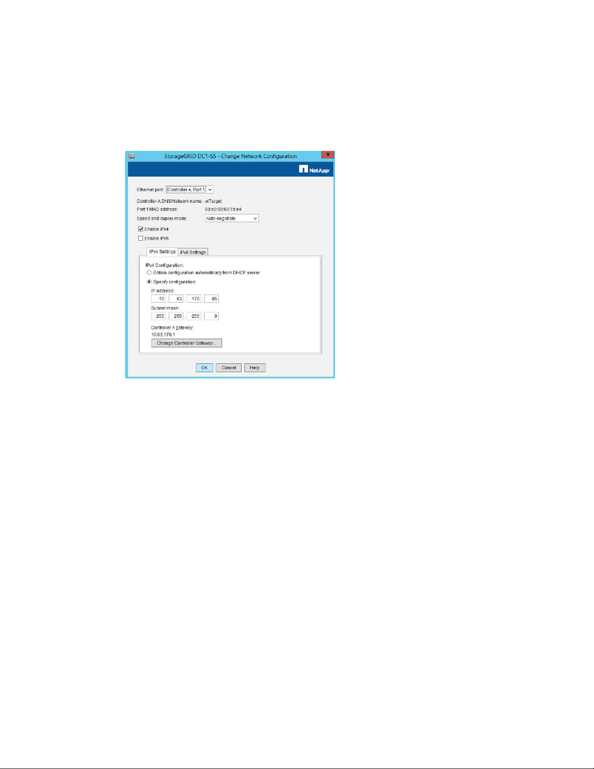
6. Change the IP address of Controller A, Port 1 to the management IP address, gateway, and subnet
mask by doing the following:
a. From the Speed and duplex mode drop-down list, select Auto-negotiate.
After you select Auto-negotiate, make sure that your Ethernet switch is also set to Autonegotiate. Connectivity issues might occur if automatic negotiation is selected in SANtricity
Storage Manager but not set for the Ethernet switch.
b. Depending on the format of your network configuration, select either Enable IPv4 or Enable
IPv6, or select both boxes.
c. Select Specify configuration, and change the IP address of Controller A, Port 1 to a routable
management IP address, gateway, and subnet mask.
d. Click OK.
7. After the change, ping the IP address using an external laptop, not the service laptop.
It might take a few minutes to get a response to the ping.
8. If the ping returns the IP data, disconnect the Ethernet cable from your service laptop, and
reconnect the cable from the controller to the management network.
9. In SANtricity Storage Manager, remove the newly added storage array and add it again using the
new IP addresses of Port 1.
10. Optionally, rename the controller by completing the following steps:
a. From the Enterprise Management Window, right-click the controller name and select
Rename.
Page 34

| StorageGRID Webscale 10.4 Appliance Installation and Maintenance Guide
34
b. Enter a new name for the controller, and click OK.
Related information
NetApp Documentation: SANtricity Storage Manager
Configuring the E5600SG controller management port
Management port 1 on the E5600SG controller connects the controller to the Admin network for
StorageGRID Webscale. You can configure this port using a web browser on the service laptop.
Additionally, you should enter the subnet mask for the network and at least a default gateway.
Before you begin
• You must have a service laptop with a web browser already installed.
Note: Mozilla Firefox is the recommended browser for this task.
About this task
If management port 1 and the 10-GbE optical ports 2 and 4 on the E5600SG controller are connected
to networks with DHCP servers, and the controller includes version 1.5 or later of the StorageGRID
Webscale Appliance Installer, the controller attempts to obtain dynamically assigned IP addresses
when you power on the enclosure. After the controller has completed the power-on process, its sevensegment display shows HO, followed by a repeating sequence of two digits.
HO -- IP address for Admin network -- IP address for Grid network HO
In the sequence:
• The first set of numbers is the DHCP-assigned IP address for management port 1 on the E5600SG
controller (if available). This address is used to connect to the Admin network for StorageGRID
Webscale.
• The second set of numbers is the DHCP-assigned IP address used to connect the appliance to the
Grid network for StorageGRID Webscale.
Note: If an IP address could not be assigned using DHCP, 0.0.0.0 is displayed.
Your network administrator can also use the controller's MAC address to look up the dynamically
assigned IP address for the controller's management port. The MAC address is printed on a label on
the back of the E5600SG controller (adjacent to the port).
Note: If the E5600SG controller includes an earlier version of the StorageGRID Webscale
Appliance Installer, the display shows IM. Earlier versions of the StorageGRID Webscale
Appliance Installer do not support the use of DHCP IP addresses.
While the DHCP-assigned addresses allow you to access the E5600SG controller initially, you must
follow the steps in this section to configure static IP addresses for all E5600SG controller interfaces.
You must also follow these steps if you have version 1.3 of the StorageGRID Webscale Appliance
Installer.
Attention: To ensure that you do not lose access to the StorageGRID Webscale appliance, NetApp
strongly recommends that you set a static IP address for all E5600SG controller interfaces. A static
IP is required for VMware-based grids.
Steps
1. Access the E5600SG controller with the service laptop.
Page 35
Option Description
Installing the appliance hardware |
35
Have DHCP-assigned IP
address
Do not have DHCP-assigned
address
Make sure the service laptop and the E5600SG controller are on the same
subnet.
a. Configure the service laptop IP address with 169.254.0.2
b. Connect the service laptop to management port 2 on the E5600SG
controller, using an Ethernet patch cord.
2. Open a web browser on the service laptop, and access the StorageGRID Webscale Appliance
Installer web page:
• Using DHCP: http://Management_Port_IP:8080
• Not using DHCP: http://169.254.0.1:8080
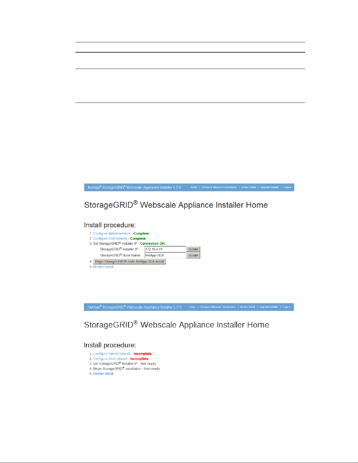
The StorageGRID Webscale Appliance Installer web page appears.
• If the StorageGRID Webscale Appliance Installer acquired an IP address using DHCP
(version 1.6 or later), the web page looks like this:
• If the StorageGRID Webscale Appliance Installer could not acquire an IP address using
DHCP, the web page looks like this:
Note: These examples show version 1.7 of the StorageGRID Webscale Appliance Installer web
page. The version number immediately follows the product name in the menu bar. Earlier
versions of this page might not include the version number in the heading.
Attention: If you want to use Aggregated Port Configuration for the StorageGRID Webscale
Grid and Client networks, you must use version 1.7 or greater of the StorageGRID Webscale
Page 36
| StorageGRID Webscale 10.4 Appliance Installation and Maintenance Guide
36
Appliance Installer. Contact technical support to upgrade the Appliance Installer to version 1.7
if required.
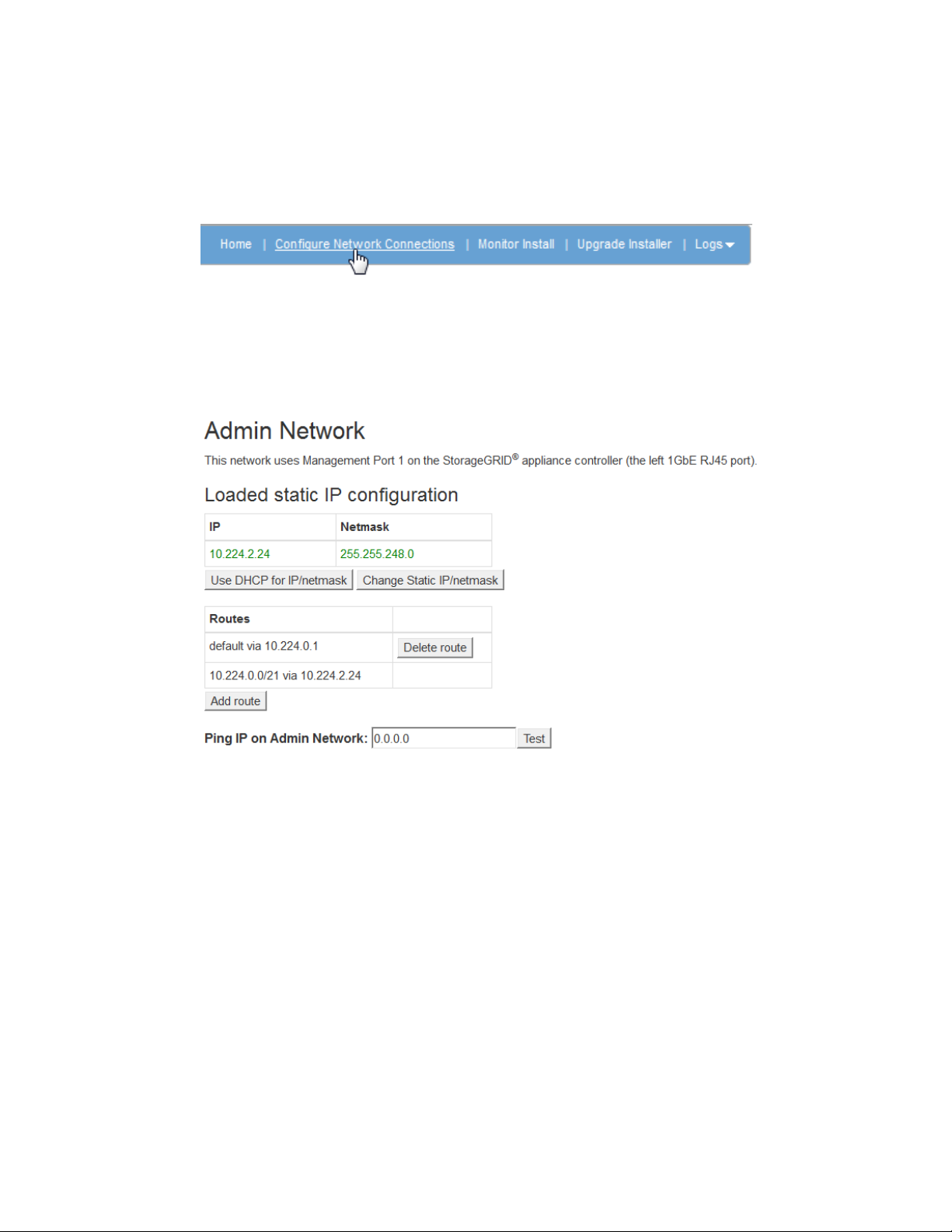
3. From the menu bar of the StorageGRID Webscale Appliance Installer web page, click Configure
Network Connections.
The Configure Network Connections page appears, with sections for configuring the 10GbE
ports, the Admin Network, the Grid Network, and the Client Network.
To set the IP address for management port 1 on the E5600SG controller, go to the Admin
4.
Network section of the page, and click Change Static IP/netmask.
The button name changes to Save Changes and a pop-up appears.
5. In the pop-up, click OK.
6. Enter the IP address for management port 1 on the controller, and click Save.
The route information is displayed, based on the specified IP address.
7. If needed, edit the route, and click Save route.
8. Click Home to return to the main Appliance Installer web page.
Verifying connectivity
You should verify the connectivity from the management ports on both the E2700 controller and the
E5600SG controller to ensure that they are working, ensure that both controllers have valid IP
addresses, and verify SAS interconnect connectivity.
Before you begin
You must have access to the service laptop with SANtricity Storage Manager installed.
Page 37

Installing the appliance hardware |
Steps
1. Verify connectivity from management port 1 on each controller to another device on the
management network by entering the IP address:
ping <IP_address>
2. In SANtricity Storage Manager, click the Devices tab of the Enterprise Management Window to
display information about the storage arrays.
3. Double-click the storage array.
In the Array Management Window, click the Hardware tab to see the configuration.
4.
Perform one of these steps, depending on the status shown:
5.
Optimal
No problems need to be resolved.
Needs Attention
Select Storage Array > Recovery Guru and follow the steps in the Recovery Guru to
resolve the issue.
Unresponsive
Refer to the online Help topics in the Enterprise Management Window for the procedure.
37
6. To verify the SAS interconnect connectivity, do the following:
• Connect to management port 2 on the E5600SG controller with an Ethernet cable.
• Open SANtricity Storage Manager on the service laptop and access the E2700 controller using
the link-local IP address 169.254.0.1.
If SANtricity Storage Manager connects to the E2700 controller, the SAS interconnect
connection is successful.
Configuring the AutoSupport tool for the StorageGRID Webscale appliance
The AutoSupport tool collects data in a customer support bundle from all AutoSupport-enabled
storage arrays and automatically sends the data to technical support. Configuring AutoSupport assists
technical support with remote troubleshooting and problem analysis of the storage management
software.
Before you begin
• The AutoSupport feature must be enabled and activated on the storage array.
The AutoSupport feature is activated and deactivated globally on a storage management station
and can be enabled or disabled for an individual storage array.
• The Storage Manager Event Monitor must be running on at least one machine with access to the
storage array and, preferably, on no more than one machine.
About this task
All of the data is compressed into a single compressed archive file format (7z) at the location you
specify.
AutoSupport provides the following types of messages:
Page 38
| StorageGRID Webscale 10.4 Appliance Installation and Maintenance Guide
38
Message types Description
Event messages
Daily messages
Weekly messages
Steps
From the Enterprise Management Window in SANtricity Storage Manager, select the Devices tab,
1.
and then select Discovered Storage Arrays.
2. Select Tools > AutoSupport > Configuration.
3. Use SANtricity Storage Manager online Help, if needed, to complete the task.
Related information
• Sent when a support event on the managed storage array occurs
• Include system configuration and diagnostic information
• Sent once every day during a user configurable time interval in the
local time of the storage array
• Include the current system event logs and performance data
• Sent once every week during a user configurable time interval in the
local time of the storage array
• Include configuration and system state information
NetApp Documentation: SANtricity Storage Manager
Configuring StorageGRID Webscale appliance passwords
Setting up AutoSupport requires that you configure passwords for the appliance. Setting passwords
maintains system security.
Steps
1. From the Enterprise Management Window in SANtricity Storage Manager, double-click the
controller.
2. From the Array Management Window, select the Storage Array menu, and select Security > Set
Password.
3. Configure the password.
4. Use SANtricity Storage Manager online Help, if needed, to complete the task.
Configuring email and SNMP alarm targets
Configuring AutoSupport requires that you identify email for notifications and SNMP alarm targets.
This enables administrators to receive timely information about alarms and operations.
Steps
1. From the Enterprise Management Window in SANtricity Storage Manager, select the Devices tab,
and then select a node.
2. Select Edit > Configure Alerts.
3. Use SANtricity Storage Manager online Help, if needed, to complete the task.
Page 39

Installing the appliance hardware |
Verifying receipt of AutoSupport
You should verify that NetApp technical support is receiving your AutoSupport messages. On the My
AutoSupport site, you can find the AutoSupport status of your systems. Verifying receipt of these
messages ensures that NetApp technical support has your information if you need assistance.
About this task
AutoSupport can show one of the following statuses:
ON
An ON status indicates that technical support is currently receiving AutoSupport messages
from the system.
OFF
An OFF status suggests that you might have disabled AutoSupport because NetApp
technical support has not received a Weekly Log from the system in the last 15 calendar
days or there might have been a change in your environment or configuration (as an
example).
DECLINE
A DECLINE status means that you have notified NetApp technical support that you will
not enable AutoSupport.
39
After NetApp receives a Weekly Log from the system, the AutoSupport status changes to ON.
Steps
1. Go to the NetApp Support Site at
2. If the AutoSupport status is OFF, and you believe that is incorrect, complete the following:
a. Check your system configuration to ensure that you have turned AutoSupport on.
b. Check your network environment and configuration to ensure that the system can send
messages to technical support.
mysupport.netapp.com
, and log in to the My AutoSupport site.
Changing the RAID volume configuration settings
If you have an SG5660 with 60 drives, you can select the RAID volume configuration that is
appropriate for your deployment environment. You can only change the RAID volume configuration
before you start the installation of the StorageGRID Webscale appliance Storage Node.
Before you begin
• You must have a service laptop with a web browser already installed.
• You must already have the IP address of the management network.
About this task
Before starting the installation of the StorageGRID Webscale appliance Storage Node, you can
choose from two volume configuration options:
• Dynamic Disk Pools (DDP) – This is the default, and recommended setting. DDP is an enhanced
hardware data protection scheme that delivers system performance, reduced rebuild times, and
ease of management.
Page 40

40 | StorageGRID Webscale 10.4 Appliance Installation and Maintenance Guide
• RAID6 – This is a hardware protection scheme that uses to parity stripes on each disk, and allows
for two disk failures within the RAID set before any data is lost. RAID6 provides improved
storage efficiency over DDP (typically 5-10%), but does not recover from failures as efficiently.
Note: The SG5612 does not support RAID6. If you have this model, you must use the DDP
option.
Steps
1. Using the service laptop, open a web browser and access the RAID6 Option web page on the
StorageGRID Webscale appliance:
http://Management_Port_IP:8080/advanced
Management_Port_IP is the IP address of management port 1 on the E5600SG controller
controller (provisioned during the physical installation).
If you want to change from the default DDP value to RAID6:
2.
a.
Click Change volume configuration to RAID6.
b.
Click OK in the confirmation dialog box.
If you have selected RAID6 and want to restore DDP:
3.
a. Click Change volume configuration to DDP.
b. Click OK in the confirmation dialog box.
Page 41
Troubleshooting the hardware installation
If you encounter issues during the installation, you might find it helpful to review troubleshooting
information related to hardware setup and connectivity issues.
Related references
41
Hardware setup appears to hang
Connectivity issues
on page 43
on page 41
Hardware setup appears to hang
Issue
The StorageGRID Webscale appliance hardware installation cannot begin or appears
halted.
Cause
This issue occurs when the hardware installation cannot locate a required installation file,
the factory image is incomplete or corrupt, or the hardware installation is still in progress.
Corrective action
1. Check the Needs Attention LED on either controller and look for a flashing error code.
During power up, the Service Action Allowed and Service Action Required LEDs are
turned on while the hardware is initializing. The upper decimal point of the lower
digit, called the
through a sequence of codes that are common for both controllers. This is normal and
is not an indication of an error. When the hardware boots successfully, the Service
Action LEDs are turned off, and the displays are driven by the firmware.
2. On the E5600SG controller controller, review the seven-segment codes that are not
errors.
diagnostic LED
, also illuminates. The seven-segment display runs
Note: The installation and provisioning take time. Some installation phases do not
report updates to the installer for several minutes.
When an error occurs, the Controller Fault LED illuminates and the seven-segment
displays flash a sequence beginning with an E code, such as EM.
3. If a seven-segment error code appears, depending on the controller, use the following
references:
Controller
E2700 controller NetApp E-Series documentation
E5600SG
controller
4. If this does not resolve the connection issue, contact technical support from the
NetApp Support Site at
Related references
E5600SG controller seven-segment display codes
Reference
Seven-segment error codes, such as EI or EM
mysupport.netapp.com
.
on page 27
Page 42

| StorageGRID Webscale 10.4 Appliance Installation and Maintenance Guide
42
Related information
E2700 Controller-Drive Tray and Related Drive Trays Installation Guide
NetApp Documentation: E2700 Series
EI or EU Error: Installation script not found
The codes that appear depend on which version of the Appliance Installer you have. The EI code
displays if you have version 1.4 or earlier. The EU code displays if you have version 1.5 or later.
Description
This message occurs when the StorageGRID Webscale appliance software installation
cannot begin, either because it cannot locate a needed installation file or because a factory
image is incomplete or corrupt.
Corrective action
Restart the installation.
1.
If this does not resolve the connection issue, contact technical support from the
2.
NetApp Support Site at
mysupport.netapp.com
.
EM or EP Error: Manage SGA returned
The codes that appear depend on which version of the Appliance Installer you have. The EM code
displays if you have version 1.4 or earlier. The EP code displays if you have version 1.5 or later.
Description
This message occurs when the pre-grid communication with the E2700 controller fails for
any of several reasons, including that the appliance is not cabled correctly, an installation
file is missing or corrupt, or a power failure occurred.
Corrective action
1. Check the cabling on the hardware.
2. Check for power issues.
3. Ping the appliance:
ping <E5600_controller_IP>
4. Check the logs on the E2700 controller.
5. Reboot the appliance.
6. Complete the steps for any unable to connect message.
7. If this does not resolve the connection issue, contact technical support fromthe NetApp
Support Site at
Related references
mysupport.netapp.com
.
Unable to connect to StorageGRID Webscale appliance over the network
on page 43
Page 43
Troubleshooting the hardware installation |
Connectivity issues
If you encounter connectivity issues during the StorageGRID Webscale appliance installation, you
might find it helpful to review troubleshooting information.
Unable to connect to StorageGRID Webscale appliance over the network
Issue
You cannot connect to the appliance.
Cause
This could occur if there is a network issue or the hardware installation did not complete
successfully.
Corrective action
Ping the appliance:
1.
ping <E5600_controller_IP>
Access the StorageGRID Webscale Appliance Installer by opening a browser and
2.
entering the following: http://<Management_Port_IP>:8080
For Management_Port_IP, enter the IP address for management port 1 on the
E5600SG controller (provisioned during the physical installation).
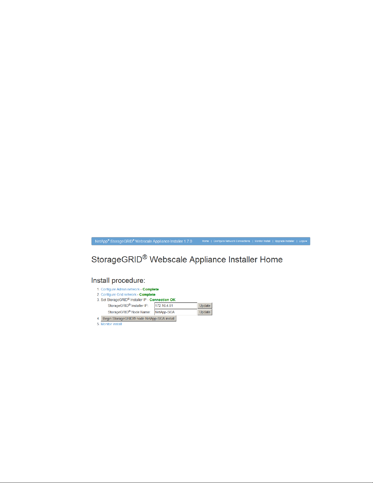
The StorageGRID Webscale Appliance Installer Home web page appears:
43
After you install the appliance, the status for each of the procedures on the web page
indicates that the procedure is complete.
3. Click Configure Admin network, and check the IP.
4. If you receive a response from the ping, check that port 8080 is open in the firewalls.
5. Reboot the appliance.
6. Refresh the installation web page.
7. If this does not resolve the connection issue, contact technical support from the
NetApp Support Site at
mysupport.netapp.com
.
Page 44
| StorageGRID Webscale 10.4 Appliance Installation and Maintenance Guide
44
Determining the StorageGRID Webscale Appliance Installer version
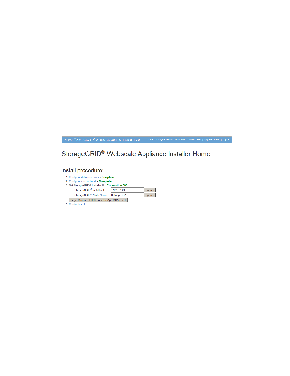
The title bar of the StorageGRID Webscale Appliance Installer shows the version number. You might
find it helpful to determine the version so that you can use the seven-segment LED codes appropriate
for the version you have.
Before you begin
• You must have a service laptop with a web browser already installed.
• You must already have the IP address of the management network.
Steps
Using the service laptop, open a web browser and access the StorageGRID Webscale Appliance
1.
Installer web page:
http://169.254.0.1:8080
2. Note the installer version in the title bar.
Note: The example shows version 1.7 of the StorageGRID Webscale Appliance Installer web
page. Earlier versions are similar, but might not include the version number in the heading.
Unable to connect to StorageGRID Webscale appliance via point-to-point Ethernet link
Issue
The appliance card fails to boot successfully.
Cause
This issue could occur if the appliance card does not connect due to a networking issue
with the service laptop.
Corrective action
1. Make sure that the seven-segment displays indicate that the appliance is booted and
ready.
2. Verify that the installer's laptop is configured and capable of connecting to a link-local
connection.
3. Reboot the appliance.
4. Refresh the installation web page.
5. Restart the installation.
Page 45

Related references
Troubleshooting the hardware installation | 45
E5600SG controller seven-segment display codes
on page 27
Page 46

46
Maintaining your StorageGRID Webscale appliance
You might need to upgrade the E-Series SANtricity OS controller software on the E2700 controller
or replace the E2700 controller, the E5600SG controller, or specific components.
Upgrading controller software on the E2700 controller
You might need to upgrade the SANtricity OS controller software on an E2700 controller if the
controller is operational but not functioning optimally, or if you want to use the new features in a new
software release.
Before you begin
You must have access to the online help for the SANtricity Storage Manager Enterprise Management
Window or the
Note: You can use the Enterprise Management Window to perform both major upgrades and minor
upgrades. You can use the Array Management Window to perform minor upgrades only.
SANtricity Storage Manager System Upgrade Guide
.
About this task
SANtricity OS controller software upgrades should not be applied to the E2700 controller unless the
controller software release is specifically stated to be compatible with the StorageGRID Webscale
appliance.
The E2700 controller used in the StorageGRID Webscale appliance supports E-Series SANtricity OS
Controller Software version 8.30.x only. You should not install a different version.
Note: Contact technical support with any upgrade-related questions.
Steps
1. Download the controller software installation files.
a. Go to
b. Locate E-Series/EF-Series SANtricity OS Controller Software.
c. For the platform, select E2700.
d. Select the version of E-Series SANtricity OS controller software you want to install, and click
e. Follow the online instructions to download the appropriate ZIP or TAR file for the E2700
2. If the StorageGRID Webscale appliance is running in a StorageGRID Webscale system, shut
down the E5600SG controller.
NetApp Downloads: Software
View & Download.
controller in your StorageGRID Webscale appliance.
and sign in.
a. From the service laptop, log in to the grid node:
i. Enter the following command: ssh admin@grid_node_IP
ii. Enter the password listed in the Passwords.txt file.
iii. Enter the following command to switch to root: su -
Page 47

Maintaining your StorageGRID Webscale appliance |
iv. Enter the password listed in the Passwords.txt file.
Once logged in as root, the prompt changes from $ to #.
b. Stop all StorageGRID Webscale services:
/etc/init.d/servermanager stop
c. Shut down the E5600SG controller:
shutdown -h now
Shutting down the E5600SG controller interrupts the connectivity to the E2700 controller, so
you can apply the controller software upgrade.
47
Refer to the
3.
Manager online Help, and upgrade the E2700 controller's firmware, NVSRAM, or both.
Attention: If you need to upgrade the NVSRAM in the E2700 controller, you must confirm
that the SANtricity OS file you downloaded was designated as compatible with StorageGRID
Webscale appliances.
Once the upgrade operation has completed, power cycle the StorageGRID Webscale appliance.
4.
a. Turn off both power switches, and wait until all LED and seven-segment display activity has
stopped.
b. Turn on both power switches.
c. Wait 10 minutes. Confirm that none of the amber LEDs on the front or back of the shelf are
lit.
5. Monitor the seven-segment codes.
• E2700 controller:
The final LED state is 99.
• E5600SG controller:
The final LED state is HA for version 1.5 or later, or SG for version 1.3.
Related information
SANtricity Storage Manager System Upgrade Guide
or the SANtricity Storage
NetApp E-Series and EF-Series Systems Documentation Center
SANtricity Storage Manager 11.30 Upgrade Guide
Replacing the E2700 controller
You might need to replace the E2700 controller. The process for replacing the controller depends on
whether the controller is operational.
Before you begin
You must have access to the following resources:
• E-Series hardware replacement information on the Support Site
• E2700 controller documentation on the Support Site
Related information
NetApp E-Series and EF-Series Hardware Replacement Procedures
NetApp Documentation: E2700 Series
Page 48

| StorageGRID Webscale 10.4 Appliance Installation and Maintenance Guide
48
Replacing an operational E2700 controller
You might need to replace an operational E2700 controller if it is not functioning optimally. For
example, you might need to replace an operational controller that repeatedly hangs and needs to be
rebooted or one that does not always reboot successfully.
About this task
If both controllers are functioning sufficiently to allow for a controlled shutdown, you can shut down
the E5600SG controller to interrupt the connectivity to the E2700 controller.
Steps
Put on antistatic protection.
1.
Label each cable attached to the E2700 controller, so you can reconnect the cables correctly.
2.
If the StorageGRID Webscale appliance is running in a StorageGRID Webscale system, shut
3.
down the E5600SG controller.
a. From the service laptop, log in to the grid node:
i. Enter the following command: ssh admin@grid_node_IP
ii. Enter the password listed in the Passwords.txt file.
iii. Enter the following command to switch to root: su -
iv. Enter the password listed in the Passwords.txt file.
Once logged in as root, the prompt changes from $ to #.
b. Stop all StorageGRID Webscale services:
/etc/init.d/servermanager stop
c. Shut down the E5600SG controller:
shutdown -h now
Shutting down the E5600SG controller interrupts the connectivity to the E2700 controller, so
you can replace it.
4. Turn off power to the enclosure, which turns power off to both controllers.
5. Wait until all LED and seven-segment display activity on the rear of the controller has stopped.
6. Remove the cables.
7. Remove the controller, as described in the E2700 controller documentation.
8. Insert the new controller, as described in the E2700 controller documentation.
9. Replace all cables.
10. Turn the power on to the controller.
11. Monitor the seven-segment codes.
• E2700 controller:
The final LED state is 99.
• E5600SG controller:
The final LED state is HA for version 1.5 or later, or SG for version 1.3.
Page 49

Maintaining your StorageGRID Webscale appliance |
Related information
NetApp E-Series and EF-Series Hardware Replacement Procedures
NetApp Documentation: E2700 Series
Replacing a failed E2700 controller
If the E2700 controller has failed, you must replace it. In this case, you cannot perform a controlled
shutdown.
Steps
Put on antistatic protection.
1.
Label each cable attached to the E2700 controller, so you can reconnect the cables correctly.
2.
Turn off power to the enclosure, which turns power off to both controllers.
3.
Wait until all LED and seven-segment display activity on the rear of the controller has stopped.
4.
Remove the cables.
5.
Remove the controller, as described in the E2700 controller documentation.
6.
49
7. Insert the new controller, as described in the E2700 controller documentation.
8. Replace all cables.
9. Turn the power back on to the enclosure.
Replacing the E5600SG controller
You might need to replace the E5600SG controller.
Before you begin
You must have access to the following resources:
• E-Series hardware replacement information on the NetApp Support Site at
• E5600 documentation on the Support Site
About this task
If both controllers are functioning sufficiently to allow for a controlled shutdown, you can shut down
the E5600SG controller first to interrupt the connectivity to the E2700 controller.
Steps
1. Use antistatic protection.
mysupport.netapp.com
2. Label each cable that is attached to the E5600SG controller, so you can reconnect the cables
correctly.
Attention: To prevent degraded performance, do not twist, fold, pinch, or step on the cables.
Do not bend the cables tighter than a 5-cm (2-in) radius.
3. If the StorageGRID Webscale appliance is running in a StorageGRID Webscale system, shut
down the E5600SG controller.
a. From the service laptop, log in to the grid node:
Page 50

| StorageGRID Webscale 10.4 Appliance Installation and Maintenance Guide
50
i. Enter the following command: ssh admin@grid_node_IP
ii. Enter the password listed in the Passwords.txt file.
iii. Enter the following command to switch to root: su -
iv. Enter the password listed in the Passwords.txt file.
Once logged in as root, the prompt changes from $ to #.
b. Stop all StorageGRID Webscale services:
/etc/init.d/servermanager stop
c. Shut down the E5600SG controller:
shutdown -h now
Turn off the power to the enclosure, and wait until all LED and seven-segment display activity on
4.
the rear of the controller has stopped.
Remove the cables.
5.
Remove the controller, as described in the E5600SG controller documentation.
6.
7. Insert the new controller, as described in the E5600SG controller documentation.
8. Replace all cables.
9. Turn the power back on to the enclosure.
10. Monitor the seven-segment codes.
• E2700 controller:
The final LED state is 99.
• E5600SG controller:
The final LED state is HA for version 1.5 or later, or SG for version 1.3.
11. Verify post-replacement operation by checking that the Storage Node appears accurately in the
Grid Management Interface and that no alarms appear.
Related information
NetApp E-Series and EF-Series Hardware Replacement Procedures
NetApp Documentation: E5600 Series
Replacing components in the StorageGRID Webscale appliance
You might need to replace a drive, fan canister, or power canister in the StorageGRID Webscale
appliance.
Before you begin
You must have access to the E-Series hardware replacement information on the Support Site.
About this task
To replace the drive, fan canister, or power canister, use the standard procedures for an E2700 series
system.
Page 51

Maintaining your StorageGRID Webscale appliance | 51
Note: The SG5612 model includes a combined power-fan canister.
Related information
NetApp E-Series and EF-Series Hardware Replacement Procedures
NetApp Documentation: E2700 Series
Page 52

52
Where to go next
After you install the StorageGRID Webscale appliance, you might want to perform additional
StorageGRID Webscale configuration steps.
You might want to complete the following tasks:
• Install and configure the StorageGRID Webscale software.
See the software installation instructions.
See the
• Integrate and verify client API connections (CDMI, S3, or Swift).
See the appropriate API guide.
You use SANtricity Storage Manager to complete the following tasks:
• Connect to each StorageGRID Webscale appliance.
• Verify receipt of AutoSupport data.
For details, see the StorageGRID Webscale and SANtricity documentation.
Administrator Guide
for configuration information.
Related information
StorageGRID Webscale 10.4 Administrator Guide
StorageGRID Webscale 10.3 Cloud Data Management Interface Implementation Guide
StorageGRID Webscale 10.4 S3 (Simple Storage Service) Implementation Guide
StorageGRID Webscale 10.4 Swift Implementation Guide
StorageGRID Webscale 10.4 Software Installation Guide for OpenStack Deployments
StorageGRID Webscale 10.4 Software Installation Guide for VMware Deployments
StorageGRID Webscale 10.4 Software Installation Guide for Red Hat Enterprise Linux
Deployments
NetApp Documentation: SANtricity Storage Manager
Page 53
Regulatory compliance statements
This product meets the FCC radio frequency interference regulatory compliance, laser products
compliance, and regional compliance statements.
FCC radio frequency interference statement
This equipment has been tested and found to comply with the limits for a Class A digital device,
pursuant to Part 15 of the Federal Communications Commission (FCC) Rules. These limits are
designed to provide reasonable protection against harmful interference in a commercial installation.
This equipment generates, uses, and can radiate radio frequency energy and, if not installed and used
in accordance with the instructions, may cause harmful interference to radio communications.
Operation of this equipment in a residential area is likely to cause harmful interference, in which case
the user will be required to correct the interference at his/her own expense.
NetApp, Inc. is not responsible for any radio or television interference caused by unauthorized
modification of this equipment or the substitution or attachment of connecting cables and equipment
other than those specified by NetApp. It is the user’s responsibility to correct interference caused by
such unauthorized modification, substitution, or attachment.
53
Laser products statement
This equipment uses Small Form-factor Pluggable (SFP) optical transceivers, which are unmodified
Class 1 laser products pursuant to 21 CFR, Subchapter J, Section 1040.10. All optical transceivers
used with this product are required to be 21 CFR certified Class 1 laser products. For outside the
USA, this equipment has been tested and found compliant with Class 1 laser product requirements
contained in European Normalization standard EN 60825 1:2007. Class 1 levels of laser radiation are
not considered to be hazardous and are considered safe based upon current medical knowledge. This
class includes all lasers or laser systems which cannot emit levels of optical radiation above the
exposure limits for the eye under any exposure conditions inherent in the design of the laser products.
NetApp, Inc. is not responsible for any damage or injury caused by unauthorized modification of this
equipment or the substitution or attachment of connecting cables and equipment other than those
specified by NetApp. It is the user’s responsibility to correct interference caused by such
unauthorized modification, substitution, or attachment.
This Class A digital apparatus meets all requirements of the Canadian Interference-Causing
Equipment Regulations.
Cet appareil numérique de la classé A respecte toutes les exigences du Règlement sure le matèriel
brouilleur du Canada.
Page 54
| StorageGRID Webscale 10.4 Appliance Installation and Maintenance Guide
54
Japan Electronics And Information Technology Industries Association (JEITA) power
cable statement
Translation of JEITA Power Cable notice:
Do not use power cord with other products.
Translation of notice:
Use only NetApp supplied power cords with NetApp equipment.
Compliance with the Spanish Royal Decree 106/2008
Este aviso se proporciona de conformidad con, además de otros requisitos, el Real Decreto español
106/2008: El precio de venta al público de las baterías, los acumuladores y las celdas de potencia
incluye el coste de la gestión de su desecho.
Translation of Spanish Royal Decree 106/2008: This notice is provided in accordance with the Royal
Decree 106/2008 of Spain: The retail price of batteries, accumulators, and power cells includes the
cost of the environmental management of their waste.
Compliance with India E-Waste Rule 2011
This product complies with the India E-waste Rule 2011 and does not contain lead, mercury,
hexavalent chromium, polybrominated biphenyls or polybrominated di-phenyl ethers above the
maximum concentration value of 0.1% by weight in a homogeneous material and does not contain
cadmium above the maximum concentration value of 0.01% by weight in homogeneous material
except for the exemptions set in Schedule 2 of the Rule.
Page 55

Java compliance
Oracle and Java are registered trademarks of Oracle and/or its affiliates. Other names may be
trademarks of their respective owners.
55
Page 56

56
Glossary
ACL
Access control list. Specifies which users or groups of users are allowed to access an
object and what operations are permitted, for example, read, write, and execute.
active-backup mode
A method for bonding two physical ports together for redundancy.
ADC service
Administrative Domain Controller. The ADC service maintains topology information,
provides authentication services, and responds to queries from the LDR, CMN, and CLB
services. The ADC service is present on each of the first three Storage Nodes installed at a
site.
ADE
Asynchronous Distributed Environment. Proprietary development environment used as a
framework for services within the StorageGRID Webscale system.
Admin Node
The Admin Node provides services for the web interface, system configuration, and audit
logs. See also,
primary Admin Node
.
Amazon S3
Proprietary web service from Amazon for the storage and retrieval of data.
AMS service
Audit Management System. The AMS service monitors and logs all audited system events
and transactions to a text log file. The AMS service is present on the Admin Node.
API Gateway Node
An API Gateway Node provides load balancing functionality to the StorageGRID
Webscale system and is used to distribute the workload when multiple client applications
are performing ingest and retrieval operations. API Gateway Nodes include a Connection
Load Balancer (CLB) service.
ARC service
Archive. The ARC service provides the management interface with which you configure
connections to external archival storage such as the cloud through an S3 interface or tape
through TSM middleware. The ARC service is present on the Archive Node.
Archive Node
The Archive Node manages the archiving of object data to an external archival storage
system.
atom
Atoms are the lowest level component of the container data structure, and generally
encode a single piece of information.
audit message
Information about an event occurring in the StorageGRID Webscale system that is
captured and logged to a file.
Base64
A standardized data encoding algorithm that enables 8-bit data to be converted into a
format that uses a smaller character set, enabling it to safely pass through legacy systems
Page 57

that can process only basic (low order) ASCII text excluding control characters. See RFC
2045 for more details.
bundle
A structured collection of configuration information used internally by various
components of the StorageGRID Webscale system. Bundles are structured in container
format.
Cassandra
An open-source database that is scalable and distributed, provides high availability, and
handles large amounts of data across multiple servers.
CBID
Content Block Identifier. A unique internal identifier of a piece of content within the
StorageGRID Webscale system.
CDMI
Cloud Data Management Interface. An industry-standard defined by SNIA that includes a
RESTful interface for object storage. For more information, see
CIDR
Classless Inter‐Domain Routing. A notation used to compactly describe a subnet mask
used to define a range of IP addresses. In CIDR notation, the subnet mask is expressed as
an IP address in dotted decimal notation, followed by a slash and the number of bits in the
subnet. For example, 192.0.2.0/24.
www.snia.org/cdmi
Glossary |
.
57
CLB service
Connection Load Balancer. The CLB service provides a gateway into the StorageGRID
Webscale system for client applications connecting through HTTP. The CLB service is
part of the API Gateway Node.
Cloud Data Management Interface
See
CDMI
.
CMN service
Configuration Management Node. The CMN service manages system‐wide configurations
and grid tasks. The CMN service is present on the primary Admin Node.
CMS service
Content Management System. The CMS service carries out the operations of the active
ILM policy’s ILM rules, determining how object data is protected over time. The CMS
service is present on the Storage Node.
command
In HTTP, an instruction in the request header such as GET, HEAD, DELETE, OPTIONS,
POST, or PUT. Also known as an HTTP method.
container
Created when an object is split into segments. A container object lists the header
information for all segments of the split object and is used by the LDR service to assemble
the segmented object when it is retrieved by a client application.
content block ID
See
CBID
.
content handle
See
UUID
.
CSTR
Null‐terminated, variable-length string.
Page 58

| StorageGRID Webscale 10.4 Appliance Installation and Maintenance Guide
58
DC
Data Center site.
DDS service
Distributed Data Store. The DDS service interfaces with the distributed key-value store
and manages object metadata. It distributes metadata copies to multiple instances of the
distributed key-value store so that metadata is always protected against loss.
distributed key value store
Data storage and retrieval that unlike a traditional relational database manages data across
grid nodes.
DNS
Domain Name System.
enablement layer
Used during installation to customize the Linux operating system installed on each grid
node. Only the packages needed to support the services hosted on the grid node are
retained, which minimizes the overall footprint occupied by the operating system and
maximizes the security of each grid node.
Fibre Channel
A networking technology primarily used for storage.
Grid ID signed text block
A Base64 encoded block of cryptographically signed data that contains the grid ID. See
provisioning
also,
grid node
The basic software building block for the StorageGRID Webscale system, for example,
Admin Node or Storage Node. Each grid node type consists of a set of services that
perform a specialized set of tasks.
grid task
System-wide scripts used to trigger various actions that implement specific changes to the
StorageGRID Webscale system. For example, most maintenance and expansion
procedures involve running grid tasks. Grid tasks are typically long-term operations that
span many entities within the StorageGRID Webscale system. See also,
Block
.
ILM
Information Lifecycle Management. A process of managing content storage location and
duration based on content value, cost of storage, performance access, regulatory
compliance, and other factors. See also,
LACP
Link Aggregation Control Protocol. A method for bundling two or more physical ports
together to form a single logical channel.
LAN
Local Area Network. A network of interconnected computers that is restricted to a small
area, such as a building or campus. A LAN can be considered a node to the Internet or
other wide area network.
.
Task Signed Text
Admin Node
and
storage pool
.
latency
Time duration for processing a transaction or transmitting a unit of data from end to end.
When evaluating system performance, both throughput and latency need to be considered.
See also,
throughput
.
Page 59

LDR service
Local Distribution Router. The LDR service manages the storage and transfer of content
within the StorageGRID Webscale system. The LDR service is present on the Storage
Node.
LUN
See
object store
mDNS
Multicast Domain Name System. A system for resolving IP addresses in a small network
where no DNS server has been installed.
metadata
Information related to or describing an object stored in the StorageGRID Webscale
system; for example, ingest time.
MLAG
Multi-Chassis Link Aggregation Group. A type of link aggregation group that uses two
(and sometimes more) switches to provide redundancy in case one of the switches fails.
MTU
Maximum transmission unit. The largest size packet or frame that can be sent in any
transmission.
.
Glossary |
59
namespace
A set whose elements are unique names. There is no guarantee that a name in one
namespace is not repeated in a different namespace.
nearline
A term describing data storage that is neither “online” (implying that it is instantly
available, like spinning disk) nor “offline” (which can include offsite storage media). An
example of a nearline data storage location is a tape that is loaded in a tape library, but is
not mounted.
NFS
Network File System. A protocol (developed by SUN Microsystems) that enables access
to network files as if they were on local disks.
NMS service
Network Management System. The NMS service provides a web-based interface for
managing and monitoring the StorageGRID Webscale system. The NMS service is present
on the Admin Node. See also,
node ID
An identification number assigned to a service within the StorageGRID Webscale system.
Each service (such as an NMS service or ADC service) must have a unique node ID. The
number is set during system configuration and tied to authentication certificates.
NTP
Network Time Protocol. A protocol used to synchronize distributed clocks over a variable
latency network, such as the Internet.
Admin Node
.
object
An artificial construct used to describe a system that divides content into data and
metadata.
object segmentation
A StorageGRID Webscale process that splits a large object into a collection of small
objects (segments) and creates a segment container to track the collection. The segment
container contains the UUID for the collection of small objects as well as the header
Page 60

| StorageGRID Webscale 10.4 Appliance Installation and Maintenance Guide
60
information for each small object in the collection. All of the small objects in the
collection are the same size. See also,
object storage
An approach to storing data where the data is accessed by unique identifiers and not by a
user-defined hierarchy of directories and files. Each object has both data (for example, a
picture) and metadata (for example, the date the picture was taken). Object storage
operations act on entire objects as opposed to reading and writing bytes as is commonly
done with files, and provided via APIs or HTTP instead of NAS (CIFS/NFS) or block
protocols (iSCSI/ FC/FCOE).
object store
A configured file system on a disk volume. The configuration includes a specific directory
structure and resources initialized at system installation.
OID
Object Identifier. The unique identifier of an object.
primary Admin Node
Admin Node that hosts the CMN service. Each StorageGRID Webscale system has only
one primary Admin Node. See also,
provisioning
The process of generating a new or updated Recovery Package and GPT repository. See
also,
SAID
.
segment container
Admin Node
.
.
quorum
A simple majority: 50% + 1. Some system functionality requires a quorum of the total
number of a particular service type.
Recovery Package
A .zip file containing deployment-specific files and software needed to install, expand,
upgrade, and maintain a StorageGRID Webscale system. The package also contains
system-specific configuration and integration information, including server hostnames and
IP addresses, and highly confidential passwords needed during system maintenance,
upgrade, and expansion. See also,
SAID
Software Activation and Integration Data. The component in the Recovery Package that
includes the Passwords.txt file.
SATA
Serial Advanced Technology Attachment. A connection technology used to connect server
and storage devices.
SCSI
Small Computer System Interface. A connection technology used to connect servers and
peripheral devices, such as storage systems.
segment container
An object created by the StorageGRID Webscale system during the segmentation process.
Object segmentation splits a large object into a collection of small objects (segments) and
creates a segment container to track the collection. A segment container contains the
UUID for the collection of segmented objects as well as the header information for each
segment in the collection. When assembled, the collection of segments creates the original
object. See also,
object segmentation
SAID
.
.
server
Used when specifically referring to hardware. Might also refer to a virtual machine.
Page 61

service
A unit of the StorageGRID Webscale system, such as the ADC service, NMS service, or
SSM service. Each service performs unique tasks critical to the normal operations of a
StorageGRID Webscale system.
SQL
Structured Query Language. An industry-standard interface language for managing
relational databases. An SQL database is one that supports the SQL interface.
ssh
Secure Shell. A UNIX shell program and supporting protocols used to log in to a remote
computer and run commands over an authenticated and encrypted channel.
SSL
Secure Socket Layer. The original cryptographic protocol used to enable secure
communications over the Internet. See also,
SSM service
Server Status Monitor. A component of the StorageGRID Webscale software that monitors
hardware conditions and reports to the NMS service. Every grid node runs an instance of
the SSM service.
Storage Node
The Storage Node provides storage capacity and services to store, move, verify, and
retrieve objects stored on disks.
TLS
.
Glossary |
61
storage pool
The element of an ILM rule that determines the location where an object is stored.
storage volume
See
object store
StorageGRID
A registered trademark of NetApp, Inc., used for an object storage grid architecture and
software system.
Task Signed Text Block
A Base64 encoded block of cryptographically signed data that provides the set of
instructions that define a grid task.
TCP/IP
Transmission Control Protocol/Internet Protocol. A process of encapsulating and
transmitting packet data over a network. It includes positive acknowledgment of
transmissions.
throughput
The amount of data that can be transmitted or the number of transactions that can be
processed by a system or subsystem in a given period of time. See also,
Tivoli Storage Manager
IBM storage middleware product that manages storage and retrieval of data from
removable storage resources.
latency
.
TLS
Transport Layer Security. A cryptographic protocol used to enable secure communications
over the Internet. See RFC 2246 for more details.
transfer syntax
The parameters, such as the byte order and compression method, needed to exchange data
between systems.
Page 62

62 | StorageGRID Webscale 10.4 Appliance Installation and Maintenance Guide
URI
Universal Resource Identifier. A generic set of all names or addresses used to refer to
resources that can be served from a computer system. These addresses are represented as
short text strings.
UTC
A language-independent international abbreviation, UTC is neither English nor French. It
means both “Coordinated Universal Time” and “Temps Universel Coordonné.” UTC
refers to the standard time common to every place in the world.
UUID
Universally Unique Identifier. Unique identifier for each piece of content in the
StorageGRID Webscale system. UUIDs provide client applications with a content handle
that permits them to access content in a way that does not interfere with the StorageGRID
Webscale system’s management of that same content. A 128-bit number that is guaranteed
to be unique. See RFC 4122 for more details.
virtual machine (VM)
A software platform that enables the installation of an operating system and software,
substituting for a physical server and permitting the sharing of physical server resources
among several virtual servers.
VLAN
Virtual local area network (or virtual LAN). A group of devices that are located on
different LAN segments but are configured to communicate as if they were attached to the
same network switch.
WAN
Wide area network. A network of interconnected computers that covers a large geographic
area, such as a country.
XFS
A scalable, high-performance journaled file system originally developed by Silicon
Graphics.
XML
Extensible Markup Language. A text format for the extensible representation of structured
information; classified by type and managed like a database. XML has the advantages of
being verifiable, human readable, and easily interchangeable between different systems.
Page 63

Copyright information
Copyright © 1994–2017 NetApp, Inc. All rights reserved. Printed in the U.S.
No part of this document covered by copyright may be reproduced in any form or by any means—
graphic, electronic, or mechanical, including photocopying, recording, taping, or storage in an
electronic retrieval system—without prior written permission of the copyright owner.
Software derived from copyrighted NetApp material is subject to the following license and
disclaimer:
THIS SOFTWARE IS PROVIDED BY NETAPP "AS IS" AND WITHOUT ANY EXPRESS OR
IMPLIED WARRANTIES, INCLUDING, BUT NOT LIMITED TO, THE IMPLIED
WARRANTIES OF MERCHANTABILITY AND FITNESS FOR A PARTICULAR PURPOSE,
WHICH ARE HEREBY DISCLAIMED. IN NO EVENT SHALL NETAPP BE LIABLE FOR ANY
DIRECT, INDIRECT, INCIDENTAL, SPECIAL, EXEMPLARY, OR CONSEQUENTIAL
DAMAGES (INCLUDING, BUT NOT LIMITED TO, PROCUREMENT OF SUBSTITUTE
GOODS OR SERVICES; LOSS OF USE, DATA, OR PROFITS; OR BUSINESS INTERRUPTION)
HOWEVER CAUSED AND ON ANY THEORY OF LIABILITY, WHETHER IN CONTRACT,
STRICT LIABILITY, OR TORT (INCLUDING NEGLIGENCE OR OTHERWISE) ARISING IN
ANY WAY OUT OF THE USE OF THIS SOFTWARE, EVEN IF ADVISED OF THE
POSSIBILITY OF SUCH DAMAGE.
63
NetApp reserves the right to change any products described herein at any time, and without notice.
NetApp assumes no responsibility or liability arising from the use of products described herein,
except as expressly agreed to in writing by NetApp. The use or purchase of this product does not
convey a license under any patent rights, trademark rights, or any other intellectual property rights of
NetApp.
The product described in this manual may be protected by one or more U.S. patents, foreign patents,
or pending applications.
RESTRICTED RIGHTS LEGEND: Use, duplication, or disclosure by the government is subject to
restrictions as set forth in subparagraph (c)(1)(ii) of the Rights in Technical Data and Computer
Software clause at DFARS 252.277-7103 (October 1988) and FAR 52-227-19 (June 1987).
Page 64

64
Trademark information
Active IQ, AltaVault, Arch Design, ASUP, AutoSupport, Campaign Express, Clustered Data ONTAP,
Customer Fitness, Data ONTAP, DataMotion, Element, Fitness, Flash Accel, Flash Cache, Flash
Pool, FlexArray, FlexCache, FlexClone, FlexPod, FlexScale, FlexShare, FlexVol, FPolicy, Fueled by
SolidFire, GetSuccessful, Helix Design, LockVault, Manage ONTAP, MetroCluster, MultiStore,
NetApp, NetApp Insight, OnCommand, ONTAP, ONTAPI, RAID DP, RAID-TEC, SANscreen,
SANshare, SANtricity, SecureShare, Simplicity, Simulate ONTAP, Snap Creator, SnapCenter,
SnapCopy, SnapDrive, SnapIntegrator, SnapLock, SnapManager, SnapMirror, SnapMover,
SnapProtect, SnapRestore, Snapshot, SnapValidator, SnapVault, SolidFire, SolidFire Helix,
StorageGRID, SyncMirror, Tech OnTap, Unbound Cloud, and WAFL and other names are
trademarks or registered trademarks of NetApp, Inc., in the United States, and/or other countries. All
other brands or products are trademarks or registered trademarks of their respective holders and
should be treated as such. A current list of NetApp trademarks is available on the web.
http://www.netapp.com/us/legal/netapptmlist.aspx
Page 65

How to send comments about documentation and receive update notifications
You can help us to improve the quality of our documentation by sending us your feedback. You can
receive automatic notification when production-level (GA/FCS) documentation is initially released or
important changes are made to existing production-level documents.
If you have suggestions for improving this document, send us your comments by email.
To help us direct your comments to the correct division, include in the subject line the product name,
version, and operating system.
If you want to be notified automatically when production-level documentation is released or
important changes are made to existing production-level documents, follow Twitter account
@NetAppDoc.
You can also contact us in the following ways:
• NetApp, Inc., 495 East Java Drive, Sunnyvale, CA 94089 U.S.
65
• Telephone: +1 (408) 822-6000
• Fax: +1 (408) 822-4501
• Support telephone: +1 (888) 463-8277
Page 66

66 | StorageGRID Webscale 10.4 Appliance Installation and Maintenance Guide
Index
A
alarms, SNMP
configuring AutoSupport to receive email and
appliance
ports
15
replacing components
verifying connectivity
appliance deployment
gathering data for
AutoSupport
configuring email and SNMP alarms
configuring for the StorageGRID Webscale
appliance
setting storage array passwords
verifying receipt of messages by technical support
37
50
36
17
38
38
39
B
browsers
supported
13
C
cabling
appliance
connecting AC power cords
included in product shipment
turning power on
comments
how to send feedback about documentation
compliance
Java
regulatory
components
StorageGRID Webscale appliance
configuration
AutoSupport, for the StorageGRID Webscale
appliance
diagrams
connections
troubleshooting network issues
connectivity
cables included in product shipment
verifying from appliance
controller software upgrade
E2700 controller
controllers
adding in SANtricity Storage Manager
configuring E5600SG management port
replacing E5600SG
troubleshooting installation
verifying connectivity
23
25
10
26
55
53
6
37
7
43
10
36
46
49
41
36
D
deployment
31
34
65
38
planning
deployment, appliance
gathering data for
documentation
how to receive automatic notification of changes to
10
17
65
how to send feedback about
65
E
E2700 controller
connections
diagrams
replacement overview
replacing
replacing components
replacing controller
upgrading
upgrading SANtricity OS controller software
E5600SG controller
configuring management port
connections
diagrams
installing in the enclosure
replacing
seven-segment display status and error codes
email
configuring AutoSupport to receive notifications and
SNMP alarms
errors
EI code
EM code
seven-segment display
seven-segment LEDs
15
7
47
49
50
48
46
34
15
7
22
49
38
42
42
27
41
F
FCC
regulatory compliance statements
feedback
how to send comments about documentation
firmware
upgrading for E2700 controller
53
46
H
hardware
chassis installation
controller diagrams
drive installation
items included in product shipment
preparation for installation
registering
replacing the E2700 controller
replacing the E5600SG controller
troubleshooting setup
verifying connectivity
hardware installation
21
7
21
10
15
20
47
49
41
36
46
27
65
Page 67

Index | 67
adding storage array
cabling the appliance
E2700
10
E5600SG controller
31
23
22
I
information
how to send feedback about improving
documentation
installation
E5600SG controller
hardware
hardware overview
phases
post-installation tasks
safety notices
troubleshooting
troubleshooting connectivity
installer
determining version
65
22
21
20
19
52
5
41
44
J
Java
compliance information
55
L
laptop
equipment needed
legal statements
regulatory compliance
safety notices
10
53
5
M
maintenance
of appliance
replacing components
management ports
configuration overview
configuring for E5600SG controller
configuring for the E2700 controller
46
50
30
P
passwords
setting, to use AutoSupport
power
connecting AC power cords
turning on
26
R
RAID
configuring volume settings for
registration
hardware
regulatory compliance
statements
20
53
38
25
43
39
34
32
replacing
components
E2700 controller
E5600SG controller 46,
46
47
49
S
safety
connecting power cords
StorageGRID installation
turning power on
SANtricity Storage Manager
adding storage array
configuring E2700 management port
on service laptop 10,
service laptop
equipment needed
service laptops
resource requirements
seven-segment display error codes
EI
42
EM
42
shipment
content of boxes
site
preparation for controller and drive tray installations
25
5
26
31
32
12
10
12
10
15
SNMP alarms
configuring AutoSupport to receive email and
status
seven-segment display
StorageGrid Webscale appliance
configuring RAID volume settings for
StorageGRID Webscale appliance
component list and descriptions
configuring AutoSupport for
features
gathering data for deployment
overview
suggestions
how to send feedback about documentation
7
6
27
39
6
37
17
T
tools
required to install product components
troubleshooting
connectivity
hardware setup hangs
installation
installation script not found
Manage SGA returned
seven-segment display
seven-segment LEDs
unable to connect to appliance over network
unable to connect to appliance via Ethernet
Twitter
how to receive automatic notification of
documentation changes
43
41
41
42
42
27
41
65
10
38
65
43
44
Page 68

68 | StorageGRID Webscale 10.4 Appliance Installation and Maintenance Guide
U
upgrading
SANtricity OS controller software
W
Warning
46
icon and safety notice text
web browsers
supported
workflow
hardware installation
13
5
20
 Loading...