

Page 1

StorageGRID® Webscale 11.1
Hardware Installation and
Maintenance Guide
For StorageGRID Webscale SG6000 Series Appliances
December 2018 | 215-13530_B0
[email protected]
Page 2

Page 3

Contents
StorageGRID Webscale appliance overview .............................................. 5
Installation overview .................................................................................. 10
Preparing for installation ........................................................................... 12
Installing the hardware .............................................................................. 24
Configuring the hardware ......................................................................... 35
Where to go next ......................................................................................... 58
Troubleshooting the hardware installation .............................................. 59
Table of Contents |
Controllers in the SG6000 appliance .......................................................................... 7
Preparing the site ....................................................................................................... 12
Unpacking the boxes ................................................................................................. 13
Obtaining additional equipment and tools ................................................................ 14
Web browser requirements ........................................................................................ 15
Reviewing appliance network connections ............................................................... 16
10/25-GbE port connections for the SG6000-CN controller ........................ 16
Gathering installation information ............................................................................ 18
Registering the hardware ........................................................................................... 24
Installing the E2860 controller shelf in a cabinet or rack ......................................... 25
Installing drives in the E2860 controller shelf .......................................................... 27
Installing the SG6000-CN controller in a cabinet or rack ......................................... 28
Cabling the appliance ................................................................................................ 29
Connecting power cords and applying power ........................................................... 31
Viewing boot-up status codes for the E2800 controllers ........................................... 32
Viewing status indicators and buttons on the SG6000-CN controller ....................... 33
Configuring SANtricity System Manager ................................................................. 35
Accessing SANtricity System Manager ........................................................ 35
Setting the IP addresses for the E2800 controllers ........................................ 37
Setting up SANtricity System Manager ........................................................ 40
Reviewing the hardware status in SANtricity System Manager ................... 41
Configuring StorageGRID Webscale connections .................................................... 42
Accessing the StorageGRID Appliance Installer .......................................... 43
Configuring network links ............................................................................. 44
Configuring StorageGRID Webscale IP addresses ....................................... 48
Verifying network connections ...................................................................... 51
Configuring the BMC interface ................................................................................. 52
Setting the IP address for the BMC management port .................................. 52
Accessing the BMC interface and changing the root password .................... 54
Configuring SNMP settings for the SG6000-CN controller ......................... 55
Optional: Changing to RAID6 mode ........................................................................ 56
Optional: Remapping network ports for the appliance ............................................. 57
Viewing boot-up codes for the SG6000-CN controller ............................................. 59
Viewing error codes for the SG6000-CN controller ................................................. 60
3
Page 4

4 | Hardware Installation and Maintenance Guide for SG6000 Appliances
Hardware setup appears to hang ................................................................................ 62
Troubleshooting connection issues ........................................................................... 62
Unable to connect to the appliance ............................................................... 62
Rebooting the SG6000-CN controller while the StorageGRID Appliance
Installer is running ............................................................................................... 63
Maintaining the SG6000 appliance ........................................................... 65
Upgrading SANtricity OS Software on the E2800 controllers ................................. 65
Replacing an E2800 controller .................................................................................. 67
Replacing hardware components in the E2860 controller shelf ................................ 72
Replacing the SG6000-CN controller ....................................................................... 73
Replacing a power supply in the SG6000-CN controller .......................................... 74
Changing the link configuration of the SG6000-CN controller ................................ 76
Copyright information ............................................................................... 79
Trademark .................................................................................................. 80
How to send comments about documentation and receive update
notifications ............................................................................................ 81
Index ............................................................................................................. 82
Page 5

StorageGRID Webscale appliance overview
The StorageGRID Webscale SG6000 appliance is an integrated storage and computing platform that
operates as a Storage Node in a StorageGRID Webscale grid. The appliance can be used in a hybrid
grid environment that combines appliance Storage Nodes and virtual (software-based) Storage
Nodes.
The SG6000 appliance provides the following features:
• Integrates the storage and computing elements for a StorageGRID Webscale Storage Node.
• Includes the StorageGRID Appliance Installer to simplify Storage Node deployment and
configuration.
• Includes SANtricity System Manager for managing and monitoring the storage controllers and
drives.
• Includes a baseboard management controller (BMC) for monitoring and diagnosing the hardware
in the compute controller.
• Supports up to four 10-GbE or 25-GbE connections to the StorageGRID Webscale Grid Network
and Client Network.
5
• Supports Federal Information Processing Standard (FIPS) drives. When these drives are used with
the Drive Security feature in SANtricity System Manager, unauthorized access to data is
prevented.
Model SG6060 components
The SG6000 appliance is available in the SG6060 model, which includes the following components:
Component
Compute controller SG6000-CN controller, a one-rack unit (1U) server, which
Storage controller shelf
Description
includes:
• 40 cores (80 threads)
• 192 GB RAM
• Up to 4 x 25 Gbps aggregate Ethernet bandwidth
• 4 x 16 Gbps Fibre Channel (FC) interconnect
• Baseboard management controller (BMC) that
simplifies hardware management
• Redundant power supplies
E-Series E2860 controller shelf (storage array), a 4U shelf
which includes:
• Two E-Series E2800 controllers (duplex configuration)
to provide storage controller failover support
• Five-drawer drive shelf that holds sixty 3.5-inch drives
(2 SSD and 58 NL-SAS)
• Redundant power supplies and fans
Page 6
| Hardware Installation and Maintenance Guide for SG6000 Appliances
6
The maximum raw storage available in the StorageGRID Webscale appliance is limited to drives
within the single storage controller shelf. You cannot expand the available storage by adding a shelf
with additional drives.
Model SG6060 diagrams
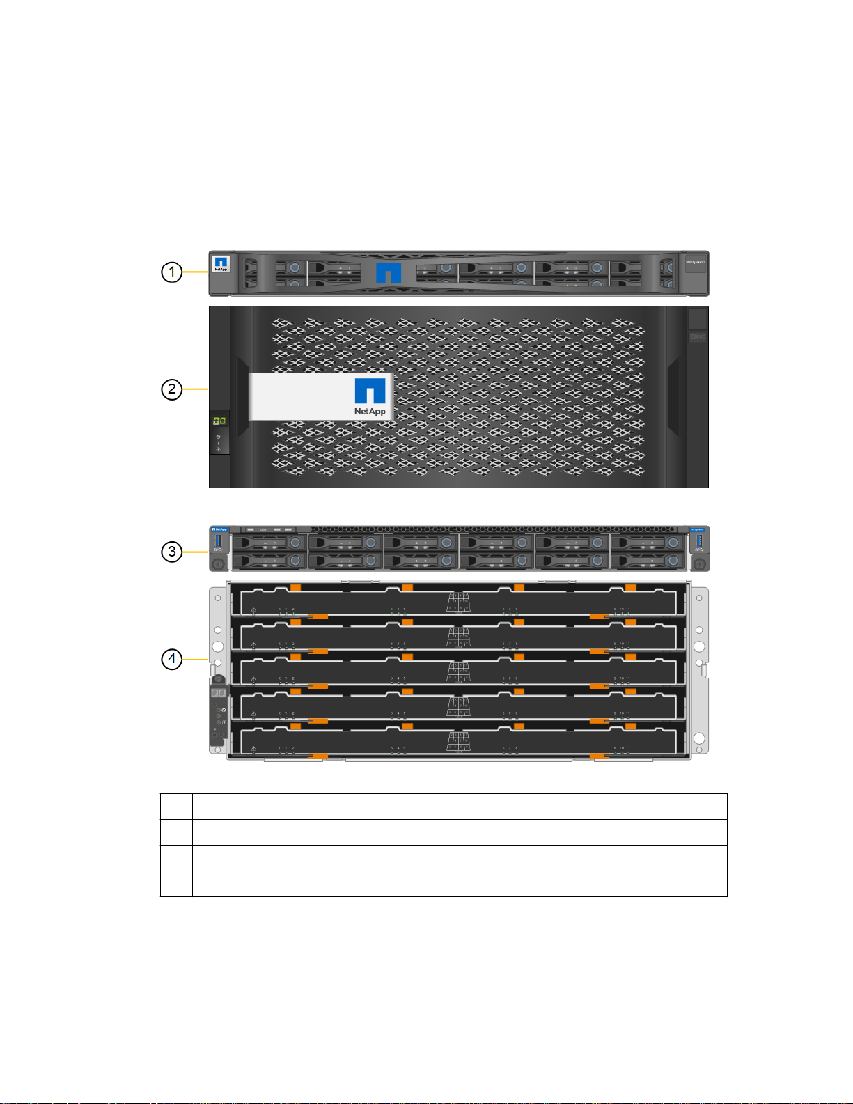
This figure shows the front of the SG6060 model, which includes a 1U compute controller, and a 4U
enclosure containing the storage controllers and 60 drives in five drive drawers.
1
SG6000-CN compute controller with front bezel
2 E2860 controller shelf with front bezel
3 SG6000-CN compute controller with front bezel removed
4 E2860 controller shelf with front bezel removed
This figure shows the back of the SG6060 model, including the compute and storage controllers,
fans, and power supplies.
Page 7

StorageGRID Webscale appliance overview |
7
1
Power supply (1 of 2) for SG6000-CN compute controller
2 Connectors for SG6000-CN compute controller
3 Fan (1 of 2) for E2860 controller shelf
4 E-Series E2800 storage controller (1 of 2) and connectors
5 Power supply (1 of 2) for E2860 controller shelf
Controllers in the SG6000 appliance
The SG6060 model of the StorageGRID Webscale SG6000 appliance includes an SG6000-CN
compute controller in a 1U enclosure and two E2800 storage controllers in a 4U, 60-drive controller
shelf. Review the diagrams to learn more about each type of controller.
SG6000-CN compute controller
• Provides compute resources for the appliance.
• Includes the StorageGRID Appliance Installer.
Note: StorageGRID Webscale software is not preinstalled on the appliance. This software is
retrieved from the Admin Node when you deploy the appliance.
• Can connect to all three StorageGRID Webscale networks, including the Grid Network, the
Admin Network, and the Client Network.
• Connects to the two E2800 controllers and operates as the initiator.
This figure shows the connectors on the back of the SG6000-CN.
Page 8

| Hardware Installation and Maintenance Guide for SG6000 Appliances
8
Port Type Use
1 Interconnect
ports 1-4
2 Network ports
1-4
3 BMC
management
port
4 Diagnostic and
support ports
5 Admin Network
ports 1 and 2
16-Gb/s Fibre Channel
(FC), with integrated optics
10-GbE or 25-GbE, based
on cable or SFP transceiver
type, switch speed, and
configured link speed
1-GbE (RJ-45) Connects to the SG6000-CN baseboard
• VGA
• Serial, 115200 8-N-1
• USB
1-GbE (RJ-45)
Connect the SG6000-CN controller to the
E2800 controllers (two connections to
each E2800).
Connect to the Grid Network and the
Client Network for StorageGRID
Webscale.
management controller.
Reserved for technical support use.
• The left (primary) port connects the
SG6000-CN to the Admin Network for
StorageGRID Webscale.
• The right port can be used to connect
the SG6000-CN to a service laptop
during installation, if a DHCP assigned
IP address is not available for the
primary Admin Network port.
E2800 storage controllers
• Two controllers for failover support.
• Manage the storage of data on the drives.
• Function as standard E-Series controllers in a duplex configuration.
• Include SANtricity OS Software (controller firmware).
• Include SANtricity System Manager for monitoring storage hardware and for managing alerts,
the AutoSupport feature, and the Drive Security feature.
• Connect to the SG6000-CN controller and provide access to the storage.
This figure shows the connectors on the back of each of the E2800 controllers.
Page 9

StorageGRID Webscale appliance overview | 9
Port Type Use
1 Interconnect
ports 1 and 2
2 Management
ports 1 and 2
3 Diagnostic and
support ports
4 Drive expansion
ports
16-Gb/s FC optical SFP+ Connect each of the E2800 controllers to
the SG6000-CN controller.
There are four connections to the SG6000-
CN controller (two from each E2800).
1-Gb (RJ-45) Ethernet
• RJ-45 serial port
• Micro USB serial port
• USB port
12Gb/s SAS Not used. StorageGRID Webscale
• Port 1 connects to the network where
you access SANtricity System Manager
on a browser.
• Port 2 is reserved for technical support
use.
Reserved for technical support use.
appliances do not support expansion drive
shelves.
Page 10
10
Installation overview
You can install one or more StorageGRID Webscale appliances when you first deploy StorageGRID
Webscale, or you can add appliance Storage Nodes later as part of an expansion. You might also need
to install an appliance Storage Node as part of a recovery operation.
Installing a StorageGRID Webscale appliance includes two primary phases.
Attention: Before you can use the SG6000 appliance as a Storage Node, you must install or
upgrade to StorageGRID Webscale 11.1.1 or later.
1. Installing and configuring appliance hardware
The first phase of installing a StorageGRID Webscale appliance includes these steps:
Preparing for installation:
1.
• Preparing the installation site
• Unpacking the boxes and checking the contents
• Obtaining additional equipment and tools
• Gathering IP addresses and network information
2. Installing the hardware:
• Registering the hardware
• Installing the appliance into a cabinet or rack
• Installing the drives
• Cabling the appliance
• Connecting the power cords and applying power
• Viewing boot-up status codes
3. Configuring the hardware:
• Accessing SANtricity System Manager, setting a static IP address for management port 1 on
the E2800 controller, and configuring SANtricity System Manager settings
• Accessing StorageGRID Appliance Installer and configuring the link and network IP settings
required to connect to StorageGRID Webscale networks
• Accessing the baseboard management controller (BMC) interface on the SG6000-CN
controller
2. Deploying an appliance Storage Node
After the appliance hardware has been installed and configured using these instructions, you can
deploy the appliance as a Storage Node in a StorageGRID Webscale grid.
Task
Deploying an appliance Storage Node in a new
StorageGRID Webscale grid
Adding an appliance Storage Node to an
existing StorageGRID Webscale grid
Instructions
StorageGRID Webscale installation instructions
for your platform
Instructions for expanding a StorageGRID
Webscale grid
Page 11
Task Instructions
Installation overview | 11
Deploying an appliance Storage Node as part of
a Storage Node recovery operation
Related tasks
Preparing for installation
Installing the hardware
Configuring the hardware
Related information
on page 12
on page 24
on page 35
VMware installation
Red Hat Enterprise Linux or CentOS installation
Ubuntu or Debian installation
Expanding a StorageGRID Webscale grid
Recovery and maintenance
Instructions for recovery and maintenance
Page 12
12
Preparing for installation
Preparing to install a StorageGRID Webscale appliance entails preparing the site and obtaining all
required hardware, cables, and tools. You should also gather IP addresses and network information.
Steps
1. Preparing the site on page 12
2. Unpacking the boxes on page 13
3. Obtaining additional equipment and tools on page 14
4. Web browser requirements on page 15
5. Reviewing appliance network connections on page 16
6. Gathering installation information on page 18
Preparing the site
Before installing the appliance, you must make sure that the site and the cabinet or rack you plan to
use meet the specifications for a StorageGRID Webscale appliance.
Steps
1. Confirm that the site meets the requirements for temperature, humidity, altitude range, airflow,
heat dissipation, wiring, power, and grounding. See the NetApp Hardware Universe for more
information.
2. Confirm that your location provides 240-volt AC power.
3. Obtain a 19-inch (48.3-cm) cabinet or rack to fit shelves of this size (without cables):
Controller
E2860 controller
shelf, including:
• Bezel
• 60 drives
• 2 power
canisters
• 2 controllers
• 2 fan
canisters
Height Width Depth Maximum
weight
6.87 in.
(17.46 cm)
17.66 in.
(44.86 cm)
38.25 in.
(97.16 cm)
250 lb.
(113 kg)
SG6000-CN
controller
• Bezel
• 2 power
supplies
4. Decide where you are going to install the appliance.
1.70 in.
(4.32 cm)
17.32 in.
(44.0 cm)
32.0 in.
(81.3 cm)
39 lb.
(17.7 kg)
Page 13

Preparing for installation | 13
Caution: Install hardware from the bottom to the top of the rack or cabinet to prevent the
equipment from tipping over. To ensure that the heaviest equipment is at the bottom of the
cabinet or rack, install the SG6000-CN controller above the E2860 controller shelf.
Attention: If you are installing multiple SG6060 appliances in the same rack, consider
installing all the E2860 controller shelves toward the bottom, and the SG6000-CN controllers
toward the top. Before committing to the installation, verify that the 0.5m optic cables shipped
with the SG6060 appliance, or cables that you supply, are long enough for the planned layout.
Related information
NetApp Hardware Universe
NetApp Interoperability Matrix Tool
Unpacking the boxes
Before installing the StorageGRID Webscale appliance, unpack all boxes and compare the contents
to the items on the packing slip.
SG6000-CN controller
Two front bezels
E2860 controller shelf with no drives installed
Two rail kits with instructions
60 drives (2 SSD and 58 NL-SAS)
Four handles
Page 14

14 | Hardware Installation and Maintenance Guide for SG6000 Appliances
Back brackets and cage nuts for square-hole
rack installation
Cables and connectors
The shipment for the StorageGRID Webscale appliance includes the following cables and
connectors:
Four power cords for your country
Your cabinet might have special power cords
that you use instead of the power cords that ship
with the appliance.
Four optical cables for the FC interconnect ports
Four SFP+ transceivers, which support 16-Gb/s
FC
Obtaining additional equipment and tools
Before installing the StorageGRID Webscale appliance, confirm you have all of the additional
equipment and tools that you need.
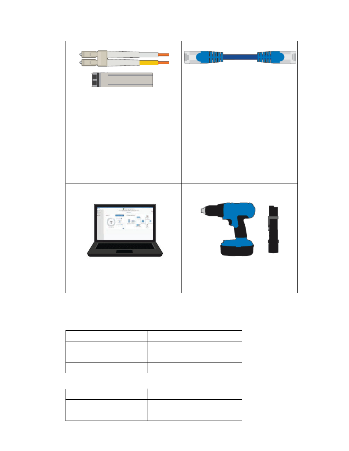
You need the following additional equipment to install and configure the hardware:
Phillips No. 2 screwdriver
Medium flat-blade screwdriver
ESD wrist strap
Page 15
Preparing for installation | 15
You need one of the following options:
• One to four TwinAx cables or optical cables
for the 10/25-GbE ports you plan to use on
the SG6000-CN controller
• One to four SFP+ transceivers for the 10/25-
GbE ports if you will use optical cables and
10-GbE link speed
• One to four SFP28 transceivers for the
10/25-GbE ports if you will use optical
cables and 25-GbE link speed
Service laptop
RJ-45 (Cat5/Cat5e/Cat6) Ethernet cables
(four minimum)
Optional tools
Supported web browser
1-GbE (RJ-45) port
Web browser requirements
You must use a supported web browser.
Web browser
Google Chrome 54
Microsoft Internet Explorer 11 (Native Mode)
Mozilla Firefox 50
You should set the browser window to a recommended width.
Browser width
Minimum 1024
Optimum 1280
Minimum supported version
Pixels
Power drill with Phillips head bit
Flashlight
Mechanized lift for E2860 controller shelf
Page 16

| Hardware Installation and Maintenance Guide for SG6000 Appliances
16
Reviewing appliance network connections
Before installing the StorageGRID Webscale appliance, you should understand which networks can
be connected to the appliance.
When you deploy a StorageGRID Webscale appliance as a Storage Node in a StorageGRID
Webscale grid, you can connect it to the following networks:
• Grid Network for StorageGRID Webscale: The Grid Network is used for all internal
StorageGRID Webscale traffic. It provides connectivity between all nodes in the grid, across all
sites and subnets. The Grid Network is required.
• Admin Network for StorageGRID Webscale: The Admin Network is a closed network used for
system administration and maintenance. The Admin Network is typically a private network and
does not need to be routable between sites. The Admin Network is optional.
• Client Network for StorageGRID Webscale: The Client Network is an open network used to
provide access to client applications, including S3 and Swift. The Client Network provides client
protocol access to the grid, so the Grid Network can be isolated and secured. The Client Network
is optional.
• Management network for SANtricity System Manager: This network provides access to
SANtricity System Manager on the E2800 controller, allowing you to monitor and manage the
hardware components in the E2860 controller shelf. This management network can be the same
as the Admin Network for StorageGRID Webscale, or it can be an independent management
network.
• BMC management network for the SG6000-CN controller: This network provides access to
the baseboard management controller in the SG6000-CN, allowing you to monitor and manage
the hardware components in the SG6000-CN controller. This management network can be the
same as the Admin Network for StorageGRID Webscale, or it can be an independent management
network.
Note: For detailed information about StorageGRID Webscale networks, see the installation
instructions for your platform.
Related concepts
10/25-GbE port connections for the SG6000-CN controller
Related tasks
Gathering installation information
Cabling the appliance
Related information
on page 29
on page 18
on page 16
VMware installation
Red Hat Enterprise Linux or CentOS installation
Ubuntu or Debian installation
10/25-GbE port connections for the SG6000-CN controller
When connecting the 10/25-GbE ports on the SG6000-CN controller to the StorageGRID Webscale
Grid Network and Client Network, you can use fixed port bond mode or aggregate port bond mode.
Page 17

Preparing for installation | 17
The port bond modes help protect your data by providing redundant paths between StorageGRID
Webscale networks and the appliance.
Related tasks
Configuring network links
on page 44
Fixed port bond mode
Fixed port bond mode is the default configuration for the 10/25-GbE ports.
Callout
Which ports are bonded
C Ports 1 and 3 are bonded together for the Client Network, if this network is used.
G Ports 2 and 4 are bonded together for the Grid Network.
When using Fixed port bond mode, the ports can be bonded using active-backup mode or Link
Aggregation Control Protocol mode (LACP 802.3ad).
• In active-backup mode (default), only one port is active at a time. If the active port fails, its
backup port automatically provides a failover connection. Port 4 provides a backup path for port 2
(Grid Network), and port 3 provides a backup path for port 1 (Client Network).
• In LACP mode, each pair of ports forms a logical channel between the controller and the network,
allowing for higher throughput. If one port fails, the other port provides a failover connection.
Throughput is reduced, but connectivity is not impacted.
Note: If you do not need redundant connections, you can use only one port for each network.
However, be aware that an alarm will be raised in the Grid Manager after StorageGRID Webscale
is installed, indicating that a cable is unplugged. You can safely acknowledge this alarm to clear it.
Aggregate port bond mode
Aggregate port bond mode significantly increases the throughout for each StorageGRID Webscale
network and provides additional failover paths.
Callout
Which ports are bonded
1 All connected ports are grouped in a single LACP bond, allowing all ports to be used
for Grid Network and Client Network traffic.
Page 18
18 | Hardware Installation and Maintenance Guide for SG6000 Appliances
If you plan to use aggregate port bond mode:
• You must specify a unique VLAN tag for each network. This VLAN tag will be added to each
network packet to ensure that network traffic is routed to the correct network.
• The ports must be connected to switches that can support VLAN and LACP. If multiple switches
are participating in the LACP bond, the switches must support multi-chassis link aggregation
groups (MLAG), or equivalent.
• You must understand how to configure the switches to use VLAN, LACP, and MLAG, or
equivalent.
If you do not want to use all four 10/25-GbE ports, you can use one, two, or three ports. Using more
than one port maximizes the chance that some network connectivity will remain available if one of
the 10/25-GbE ports fails.
Note: If you choose to use fewer than four ports, be aware that one or more alarms will be raised
in the Grid Manager after StorageGRID Webscale is installed, indicating that cables are
unplugged. You can safely acknowledge the alarms to clear them.
Gathering installation information
As you install and configure the StorageGRID Webscale appliance, you must make decisions and
gather information about Ethernet switch ports, IP addresses, and port and network bond modes.
About this task
You can use the following tables to record the required information for each network you connect to
the appliance. These values are required to install and configure the hardware.
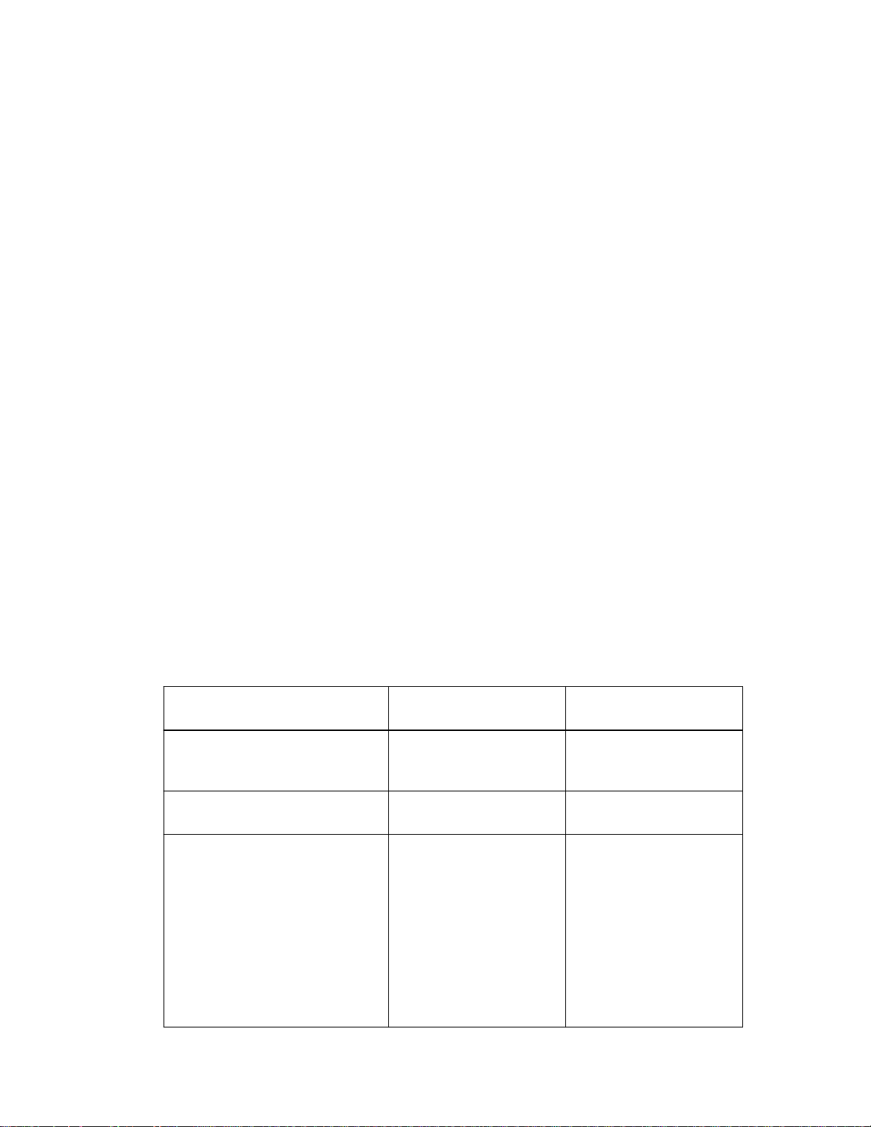
Table 1: Information needed to connect to SANtricity System Manager on the E2800
controllers
You must connect both E2800 controllers to the management network you will use for SANtricity
System Manager.
Information needed
Ethernet switch port you will
connect to management port 1
(labeled as P1 on the controller)
MAC address for management port
1 (printed on a label near port P1)
DHCP-assigned IP address for
management port 1, if available after
power on
Your value for controllerAYour value for controller
B
Note: If the network you will
connect to the E2800 controller
includes a DHCP server, the
network administrator can use the
MAC address to determine the IP
address that was assigned by the
DHCP server.
Page 19
Preparing for installation | 19
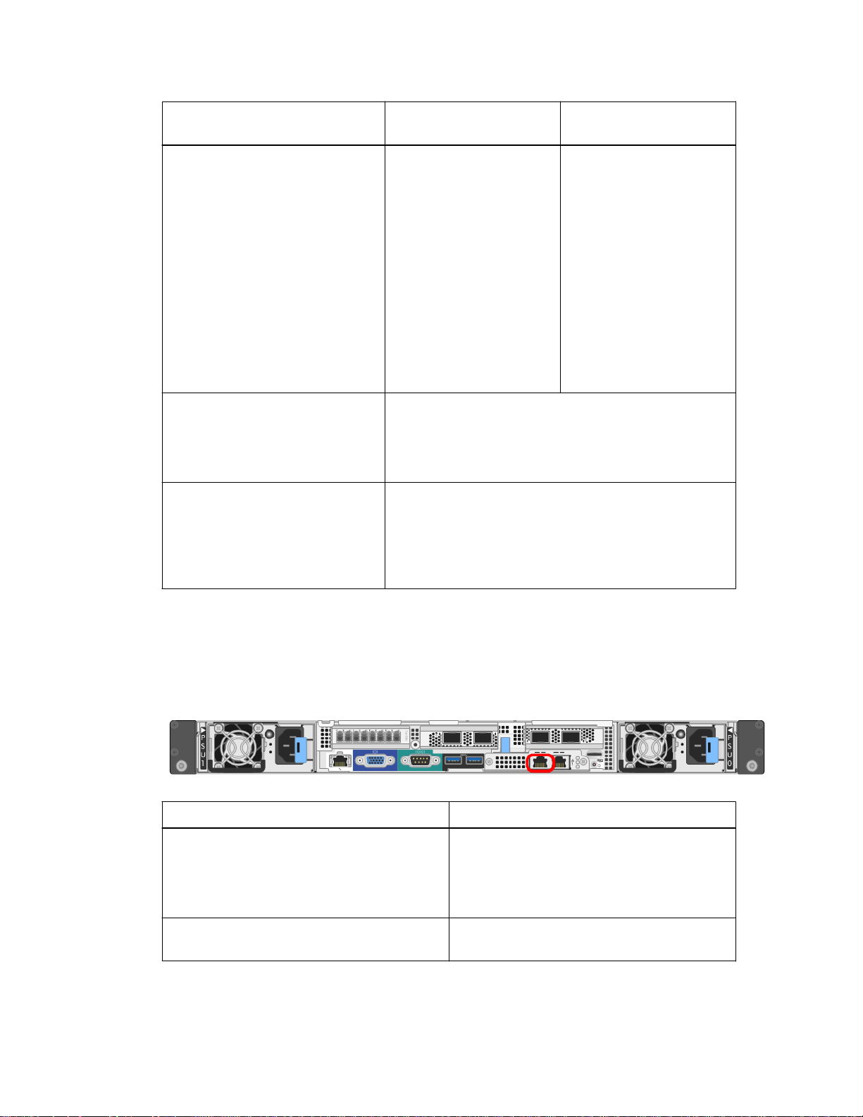
Information needed Your value for controllerAYour value for controller
B
Static IP address you plan to use for
the appliance on the management
network
IP address format
Speed and duplex mode
Note: You must make sure the
Ethernet switch for the SANtricity
System Manager management
network is set to autonegotiate.
For IPv4:
• IPv4 address:
• Subnet mask:
• Gateway:
For IPv6:
• IPv6 address:
• Routable IP address:
• E2800 controller router
IP address:
Choose one:
• IPv4
• IPv6
Must be:
• Autonegotiate (default)
For IPv4:
• IPv4 address:
• Subnet mask:
• Gateway:
For IPv6:
• IPv6 address:
• Routable IP address:
• E2800 controller router
IP address:
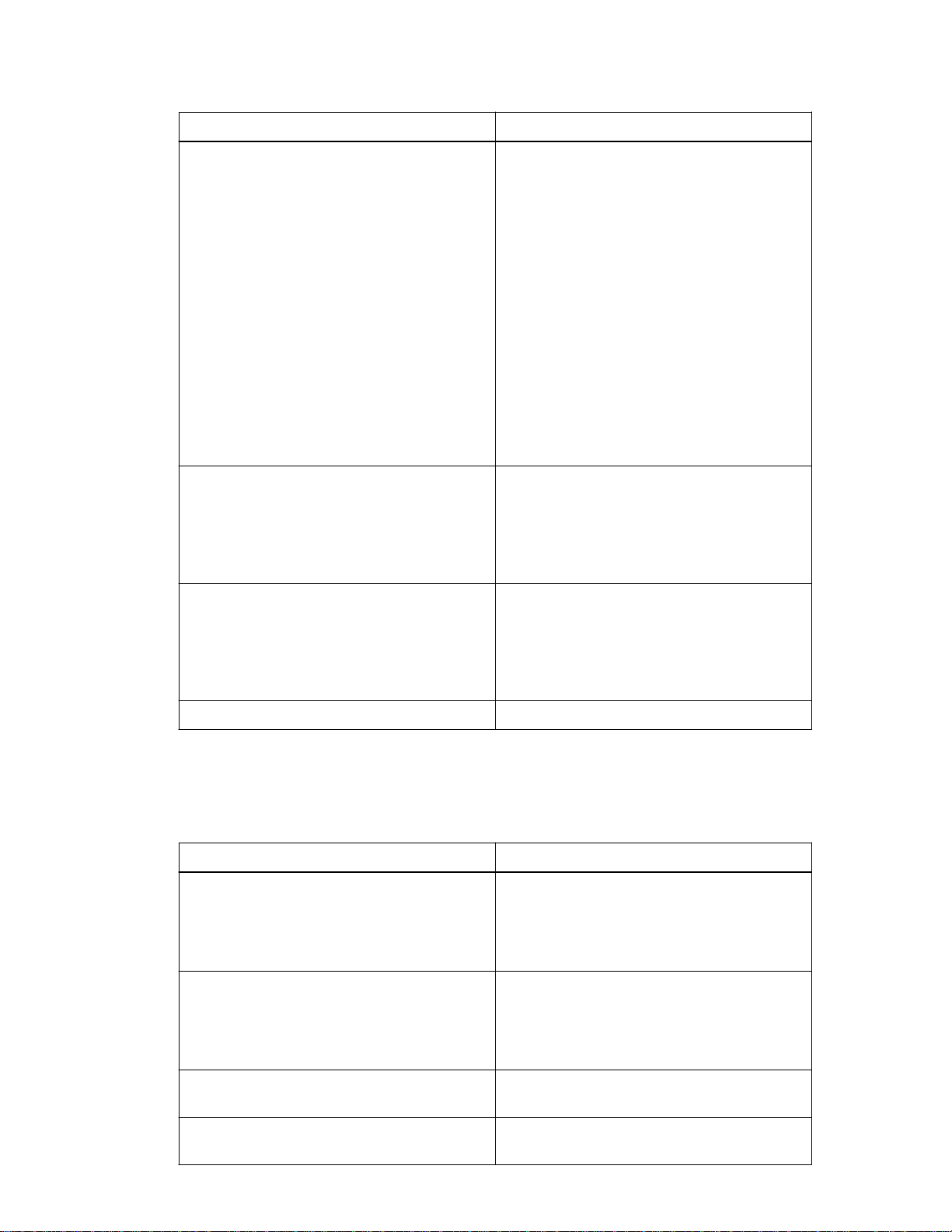
Table 2: Information needed to connect the SG6000-CN controller to the Admin
Network
The Admin Network for StorageGRID Webscale is an optional network, used for system
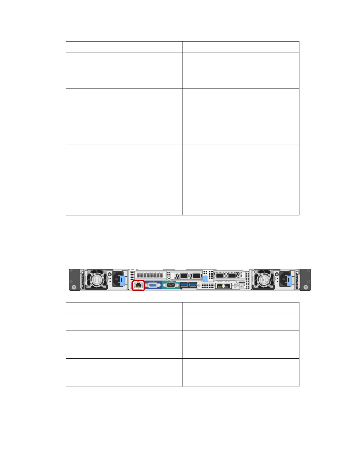
administration and maintenance. The appliance connects to the Admin Network using the following
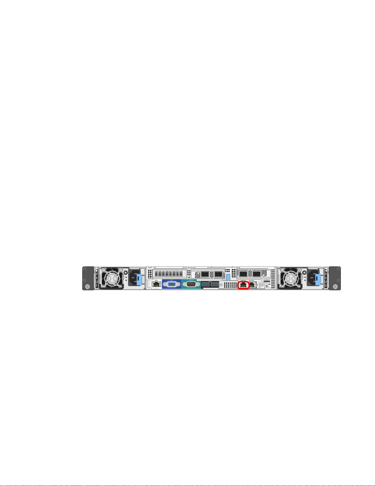
1-GbE management port on the SG6000-CN controller.
Information needed
Your value
Admin Network enabled Choose one:
• No
• Yes (default)
Ethernet switch port you will connect to the
Admin Network port (circled in the diagram)
Page 20
20 | Hardware Installation and Maintenance Guide for SG6000 Appliances
Information needed Your value
MAC address for the Admin Network port
Note: The MAC address label on the front of
the SG6000-CN controller lists the MAC
address for the BMC management port. To
determine the MAC address for the Admin
Network port, you must add 2 to the
hexadecimal number on the label. For
example, if the MAC address on the label
ends in 09, the MAC address for the Admin
Port would end in 0B. If the MAC address on
the label ends in (y)FF, the MAC address for
the Admin Port would end in (y+1)01. You
can easily make this calculation by opening
Calculator in Windows, setting it to
Programmer mode, selecting Hex, typing the
MAC address, then typing + 2 =.
DHCP-assigned IP address for the Admin
Network port, if available after power on
Note: You can determine the DHCP-assigned
• IPv4 address (CIDR):
• Gateway:
IP address by using the MAC address to look
up the assigned IP.
Static IP address you plan to use for the
appliance Storage Node on the Admin Network
Note: If your network does not have a
• IPv4 address (CIDR):
• Gateway:
gateway, specify the same static IPv4 address
for the gateway.
Admin Network subnets (CIDR)
Table 3: Information needed to connect and configure the 10/25-GbE ports on the
SG6000-CN controller
The four 10/25-GbE ports on the SG6000-CN controller connect to the StorageGRID Webscale Grid
Network and the optional Client Network.
Information needed
Your value
Link speed Choose one:
• 10 GbE (default)
• 25 GbE
Port bond mode Choose one:
• Fixed (default)
• Aggregate
Switch port for port 1 (Client Network for Fixed
mode)
Switch port for port 2 (Grid Network for Fixed
mode)
Page 21

Preparing for installation | 21
Information needed Your value
Switch port for port 3 (Client Network for Fixed
mode)
Switch port for port 4 (Grid Network for Fixed
mode)
Table 4: Information needed to connect the SG6000-CN controller to the Grid Network
The Grid Network for StorageGRID Webscale is a required network, used for all internal
StorageGRID Webscale traffic. The appliance connects to the Grid Network using the 10/25-GbE
ports on the SG6000-CN controller.
Information needed
Your value
Network bond mode Choose one:
• Active-Backup (default)
• LACP (802.3ad)
VLAN tagging enabled Choose one:
• No (default)
• Yes
VLAN tag
Enter a value between 0 and 4095:
(if VLAN tagging is enabled)
DHCP-assigned IP address for the Grid
Network, if available after power on
• IPv4 address (CIDR):
• Gateway:
Static IP address you plan to use for the
appliance Storage Node on the Grid Network
Note: If your network does not have a
• IPv4 address (CIDR):
• Gateway:
gateway, specify the same static IPv4 address
for the gateway.
Grid Network subnets (CIDR)
Table 5: Information needed to connect the SG6000-CN controller to the Client
Network
The Client Network for StorageGRID Webscale is an optional network, typically used to provide
client protocol access to the grid. The appliance connects to the Client Network using the 10/25-GbE
ports on the SG6000-CN controller.
Information needed
Your value
Client Network enabled Choose one:
• No (default)
• Yes
Page 22
| Hardware Installation and Maintenance Guide for SG6000 Appliances
22
Information needed Your value
Network bond mode Choose one:
• Active-Backup (default)
• LACP (802.3ad)
VLAN tagging enabled Choose one:
• No (default)
• Yes
VLAN tag
Enter a value between 0 and 4095:
(If VLAN tagging is enabled)
DHCP-assigned IP address for the Client
Network, if available after power on
• IPv4 address (CIDR):
• Gateway:
Static IP address you plan to use for the
appliance Storage Node on the Client Network
Note: If the Client Network is enabled, the
• IPv4 address (CIDR):
• Gateway:
default route on the controller will use the
gateway specified here.
Table 6: Information needed to connect the SG6000-CN controller to the BMC
management network
You can access the BMC interface on the SG6000-CN controller using the following 1-GbE
management port. This port supports remote management of the controller hardware over Ethernet
using the Intelligent Platform Management Interface (IPMI) standard.
Information needed
Your value
Ethernet switch port you will connect to the
BMC management port (circled in the diagram)
DHCP-assigned IP address for the BMC
management network, if available after power
on
Static IP address you plan to use for the BMC
management port
• IPv4 address (CIDR):
• Gateway:
• IPv4 address (CIDR):
• Gateway:
Related concepts
10/25-GbE port connections for the SG6000-CN controller
on page 16
Page 23

Related tasks
Preparing for installation | 23
Cabling the appliance
Related references
on page 29
Controllers in the SG6000 appliance
Reviewing appliance network connections
on page 7
on page 16
Page 24
24
Installing the hardware
Hardware installation entails installing the SG6000-CN controller and the E2860 controller shelf into
a cabinet or rack, connecting the cables, and applying power.
Steps
1. Registering the hardware on page 24
2. Installing the E2860 controller shelf in a cabinet or rack on page 25
3. Installing drives in the E2860 controller shelf on page 27
4. Installing the SG6000-CN controller in a cabinet or rack on page 28
5. Cabling the appliance on page 29
6. Connecting power cords and applying power on page 31
7. Viewing boot-up status codes for the E2800 controllers on page 32
8. Viewing status indicators and buttons on the SG6000-CN controller on page 33
Registering the hardware
Registering the appliance hardware provides support benefits.
Steps
1. Locate the chassis serial number for the E2860 controller shelf.
You can find the number on the packing slip, in your confirmation email, or on the appliance after
you unpack it.
2. Go to the NetApp Support Site at
3. Determine whether you need to register the hardware:
If you are a... Follow these steps...
Existing NetApp customer
mysupport.netapp.com
a. Sign in with your username and password.
b. Select Products > My Products.
c. Confirm that the new serial number is listed.
.
New NetApp customer
d. If it is not, follow the instructions for new NetApp customers.
a. Click Register Now, and create an account.
b. Select Products > Register Products.
c. Enter the product serial number and requested details.
After your registration is approved, you can download any required
software. The approval process might take up to 24 hours.
Page 25

Installing the hardware |
Installing the E2860 controller shelf in a cabinet or rack
You must install a set of rails for the E2860 controller shelf in your cabinet or rack, and then slide the
controller shelf onto the rails.
Before you begin
• You have reviewed the Safety Notices document included in the box, and understand the
precautions for moving and installing hardware.
• You have the instructions packaged with the rail kit.
Caution: The appliance weighs approximately 132 lb (60 kg) without drives installed. Four people
or a mechanized lift are required to safely move the appliance.
Caution: To avoid damaging the hardware, never move the appliance if drives are installed. You
must remove all drives before moving the shelf.
Caution: Install hardware from the bottom to the top of the rack or cabinet to prevent the
equipment from tipping over. To ensure that the heaviest equipment is at the bottom of the cabinet
or rack, install the SG6000-CN controller above the E2860 controller shelf.
25
Attention: If you are installing multiple SG6060 appliances in the same rack, consider installing
all the E2860 controller shelves toward the bottom, and the SG6000-CN controllers toward the top.
Before committing to the installation, verify that the 0.5m optic cables shipped with the SG6060
appliance, or cables that you supply, are long enough for the planned layout.
Steps
1. Carefully follow the instructions for the rail kit to install the rails in your cabinet or rack.
For square hole cabinets, you must first install the provided cage nuts to secure the front and rear
of the shelf with screws.
2. Remove the outer packing box for the appliance. Then, fold down the flaps on the inner box.
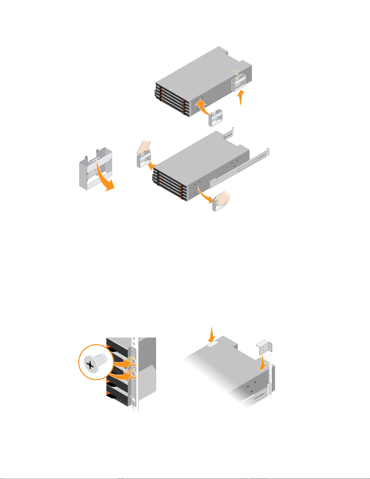
3. If you are lifting the appliance by hand, attach the four handles to the sides of the chassis.
Push up on each handle until it clicks into place.
Page 26
| Hardware Installation and Maintenance Guide for SG6000 Appliances
26
4. Place the back of the shelf (the end with the connectors) on the rails.
5. Supporting the shelf from the bottom, slide it into the cabinet. If you are using the handles, use
the thumb latches to detach one handle at a time as you slide the shelf in.
To remove the handles, pull back on the release latch, push down, then pull away from the shelf.
6. Secure the shelf to the front of the cabinet.
Insert screws into the first and third holes from the top of the shelf on both sides.
7. Secure the shelf to the rear of the cabinet.
Place two back brackets on each side of the upper rear section of the shelf. Insert screws into the
first and third holes of each bracket.
Page 27
Installing the hardware |
Installing drives in the E2860 controller shelf
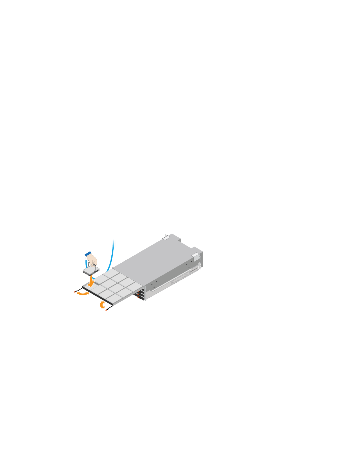
After installing the E2860 controller shelf into a cabinet or rack, you must install all 60 drives into
the shelf. The shipment includes two SSD drives, which you should install in the top drawer.
Before you begin
You have installed the E2860 controller shelf in the cabinet or rack.
Caution: To avoid damaging the hardware, never move the appliance if drives are installed. You
must remove all drives before moving the shelf.
Steps
Wrap the strap end of the ESD wristband around your wrist, and secure the clip end to a metal
1.
ground to prevent static discharge.
Remove the drives from their packaging.
2.
Locate the two SSD drives.
3.
27
4. Release the levers on the top drive drawer, and slide the drawer out using the levers.
5. Install the two SSD drives in slots 0 and 1 (the first two slots along the lefthand side of the
drawer).
Gently position each drive into its slot, and lower the raised drive handle until it clicks into place.
6. Install 10 HDD drives into the top drawer.
7. Slide the drawer back in by pushing on the center and closing both levers gently.
Attention: Stop pushing the drawer if you feel binding. Use the release levers at the front of the
drawer to slide the drawer back out. Then, carefully reinsert the drawer into the slot.
8. Repeat these steps to install HDD drives into the other four drawers.
Attention: You must install all 60 drives to ensure correct operation.
9. Attach the front bezel to the shelf.
Page 28
| Hardware Installation and Maintenance Guide for SG6000 Appliances
28
Installing the SG6000-CN controller in a cabinet or rack
You must install a set of rails for the SG6000-CN controller in your cabinet or rack, and then slide
the controller onto the rails.
Before you begin
• You have reviewed the Safety Notices document included in the box, and understand the
precautions for moving and installing hardware.
• You have the instructions packaged with the rail kit.
• You have installed the E2860 controller shelf and drives.
About this task
Caution: Install hardware from the bottom to the top of the rack or cabinet to prevent the
equipment from tipping over. To ensure that the heaviest equipment is at the bottom of the cabinet
or rack, install the SG6000-CN controller above the E2860 controller shelf.
Attention: If you are installing multiple SG6060 appliances in the same rack, consider installing
all the E2860 controller shelves toward the bottom, and the SG6000-CN controllers toward the top.
Before committing to the installation, verify that the 0.5m optic cables shipped with the SG6060
appliance, or cables that you supply, are long enough for the planned layout.
Steps
1. Carefully follow the instructions for the rail kit to install the rails in your cabinet or rack.
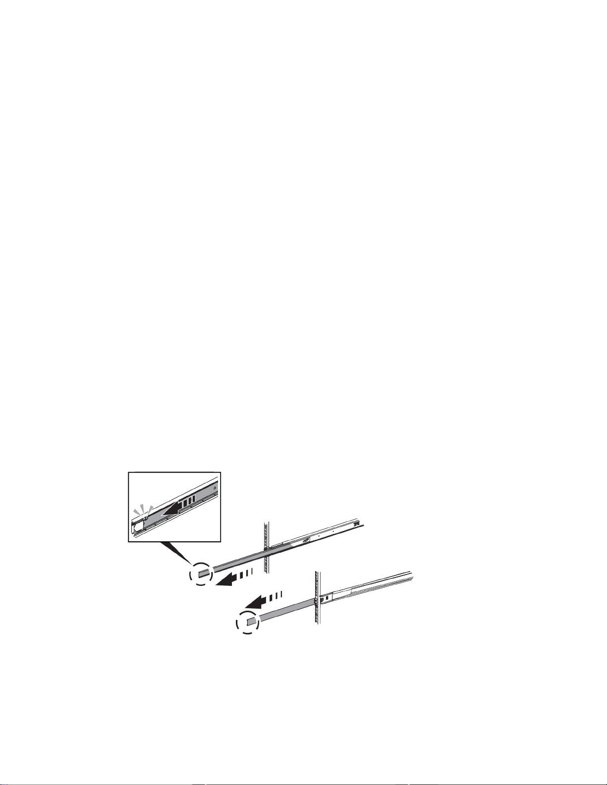
2. On the two rails installed in the cabinet or rack, extend the movable parts of the rails until you
hear a click.
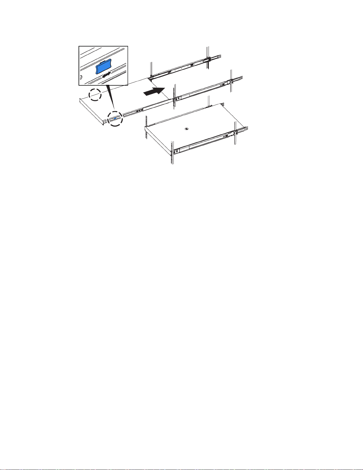
3. Insert the SG6000-CN controller into the rails.
4. Slide the controller into the cabinet or rack.
When you cannot move the controller any further, pull the blue latches on both sides of the
chassis to slide the controller all the way in.
Page 29
Note: Do not attach the front bezel until after you power on the controller.
Installing the hardware |
29
Cabling the appliance
You must connect the two E2800 controllers to the SG6000-CN controller, connect the management
ports on all three controllers, and connect the 10/25-GbE ports on the SG6000-CN controller to the
Grid Network and optional Client Network for StorageGRID Webscale.
Before you begin
• You have the four optical cables provided with the appliance for connecting the two E2800
controllers to the SG6000-CN controller.
• You have Ethernet cables (four minimum) for connecting the management ports.
• You have one of the following options for the network ports. These items are not provided with
the appliance.
◦ One to four TwinAx cables for connecting the four 10/25-GbE ports.
◦ One to four SFP+ or SFP28 transceivers if you plan to use optical cables for the ports.
Caution: Risk of exposure to laser radiation – Do not disassemble or remove any part of an SFP
transceiver. You might be exposed to laser radiation.
About this task
The figure shows the three controllers in the SG6060 appliance model, with the SG6000-CN
controller on the top and the two E2800 controllers on the bottom.
Page 30

| Hardware Installation and Maintenance Guide for SG6000 Appliances
30
Port
1 FC connection ports:
• 4 on the SG6000-CN
controller
• 2 on each E2800
controller
2 BMC management port on
the SG6000-CN controller
3 Management port 1 on each
E2800 controller
Management port 2 on each
E2800 controller
4 Four network ports on the
SG6000-CN controller
5 Admin Network port on the
SG6000-CN controller
(labelled P1 in the figure)
Rightmost RJ-45 port on
the SG6000-CN controller
Type of port Function
16-Gb/s FC optical SFP+ Connect each E2800 controller to
the SG6000-CN controller.
1-GbE (RJ-45) Connects to the network where you
access the BMC interface.
1-GbE (RJ-45) Connects to the network where you
access SANtricity System Manager.
1-GbE (RJ-45) Reserved for technical support.
10/25-GbE Connect to the Grid Network and the
Client Network for StorageGRID
Webscale.
1-GbE (RJ-45) Connects the SG6000-CN controller
to the Admin Network for
StorageGRID Webscale.
1-GbE (RJ-45) Can be used to connect the SG6000-
CN controller to a service laptop
during installation, if a DHCPassigned IP address is not available
for the Admin Network port.
Steps
1. Connect the two FC ports on each E2800 controller to the FC ports on the SG6000-CN controller,
using four optical cables and four SFP+ transceivers for the E2800 controllers.
2. Connect the BMC management port on the SG6000-CN controller to the management network,
using an Ethernet cable.
Although this connection is optional, it is recommended to facilitate support.
Page 31

Installing the hardware |
3. Connect management port 1 (P1) on each E2800 controller (the RJ-45 port on the left) to the
management network for SANtricity System Manager, using an Ethernet cable.
Do not use management port 2 (P2) on the E2800 controllers (the RJ-45 port on the right). This
port is reserved for technical support.
4. If you plan to use the Admin Network for StorageGRID Webscale, connect the Admin Network
port on the SG6000-CN controller to the Admin Network, using an Ethernet cable.
5. Connect the 10/25-GbE ports on the SG6000-CN controller to the appropriate network switches,
using TwinAx cables or optical cables and SFP+ or SFP28 transceivers.
Note: The four network ports must use the same link speed. Install SFP+ transceivers if you
plan to use 10-GbE link speeds. Install SFP28 transceivers if you plan to use 25-GbE link
speeds.
• If you plan to use Fixed port bond mode (default), connect the ports to the StorageGRID
Webscale Grid and Client Networks, as shown in the table.
31
Port
Port 1 Client Network (optional)
Port 2 Grid Network
Port 3 Client Network (optional)
Port 4 Grid Network
• If you plan to use the Aggregate port bond mode, connect one or more of the network ports to
one or more switches. You should connect at least two of the four ports to avoid having a
single point of failure. If you use more than one switch for a single LACP bond, the switches
must support MLAG or equivalent.
Related concepts
10/25-GbE port connections for the SG6000-CN controller
Connects to...
on page 16
Connecting power cords and applying power
After connecting the network cables, you are ready to apply power to the SG6000-CN controller and
to the E2860 controller shelf.
Steps
1. Confirm that the two power switches on back of the E2860 controller shelf are off.
Caution: Risk of electrical shock – Before connecting the power cords, make sure that the two
power switches on the E2860 controller shelf are off.
2. Connect a power cord to each of the two power supply units in the SG6000-CN controller.
3. Connect these two power cords to two different power distribution units (PDUs) in the cabinet or
rack.
4. Connect a power cord to each of the two power supply units in the E2860 controller shelf.
5. Connect these two power cords to two different PDUs in the cabinet or rack.
6. If the power button on the front of the SG6000-CN controller is not currently illuminated blue,
press the button to turn on power to the controller.
Do not press the power button again during the power-on process.
Page 32

| Hardware Installation and Maintenance Guide for SG6000 Appliances
32
7. Turn on the two power switches on the back of the E2860 controller shelf.
• Do not turn off the power switches during the power-on process.
• The fans in the E2860 controller shelf are very loud when they first start up. The loud noise
during start-up is normal.
8. After the components have booted up, check their status.
• Check the seven-segment display on the back of each E2800 controller. Refer to the topic
about viewing boot-up status codes for more information.
• Verify that the power button on the front of the SG6000-CN controller is lit.
If errors occur, correct any issues.
9.
Attach the front bezel to the SG6000-CN controller.
10.
Related tasks
Viewing boot-up status codes for the E2800 controllers
Related references
Viewing status indicators and buttons on the SG6000-CN controller
on page 32
on page 33
Viewing boot-up status codes for the E2800 controllers
Each E2800 controller has a seven-segment display that provides status codes as the controller
powers up.
About this task
For descriptions of these codes, see the
Steps
1. During boot-up, monitor progress by viewing the codes shown on the seven-segment display for
each E2800 controller.
The seven-segment display on each E2800 controller shows the repeating sequence OS, Sd,
blank to indicate that the controller is performing start-of-day processing.
2. After the controllers have booted up, confirm that each E2800 controller shows 99, which is the
default ID for an E-Series controller shelf.
E5700 and E2800 System Monitoring Guide
.
Make sure this value is displayed on both E2800 controllers.
3. If one or both controllers show other values, see the information about troubleshooting the
hardware installation, and confirm you completed the installation steps correctly. If you are
unable to resolve the problem, contact technical support.
Page 33
Related references
Installing the hardware |
33
Troubleshooting the hardware installation
Related information
on page 59
E5700 and E2800 System Monitoring Guide
NetApp Support
Viewing status indicators and buttons on the SG6000-CN controller
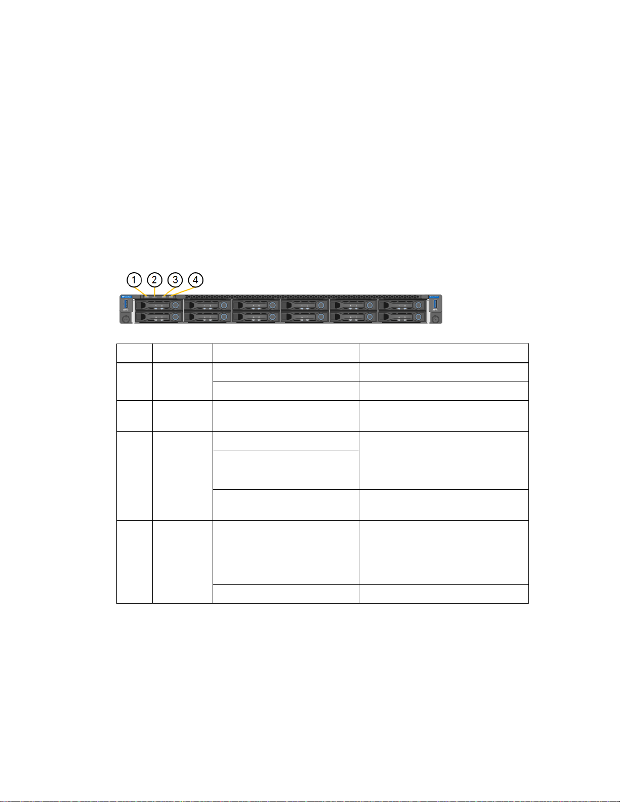
The SG6000-CN controller includes indicators that help you determine the status of the controller,
including the following indicators and buttons.
Display
1 Power
button
State Description
Blue The controller is powered on.
Off The controller is powered off.
2 Reset button
3 Identify
button
4 Alarm LED Amber An error has occurred.
General boot-up codes
During boot-up or after a hard reset of the SG6000-CN controller, the following occurs:
1. The baseboard management controller (BMC) logs codes for the boot-up sequence, including any
errors that occur.
2. The power button lights up.
Not applicable
Blinking blue Identifies the controller in the cabinet
Solid blue
Off The controller is not visually
Off No errors are present.
Use this button to perform a hard reset
of the controller.
or rack.
This button can be set to Blink, On
(Solid), or Off.
identifiable in the cabinet or rack.
Note: To view the boot-up and error
codes, you must access the BMC
interface.
3. If any errors occur during boot-up, the alarm LED lights up.
To view the boot-up and error codes, you must access the BMC interface.
Page 34

34 | Hardware Installation and Maintenance Guide for SG6000 Appliances
Related tasks
Configuring the BMC interface
Related references
on page 52
Troubleshooting the hardware installation
on page 59
Page 35

Configuring the hardware
After applying power to the appliance, you must configure SANtricity System Manager, which is the
software you will use to monitor the E2800 controllers and other hardware in the E2860 controller
shelf. You must also configure the network connections that will be used by StorageGRID Webscale
and ensure that you can access the BMC interface for the SG6000-CN controller.
Steps
1. Configuring SANtricity System Manager on page 35
2. Configuring StorageGRID Webscale connections on page 42
3. Configuring the BMC interface on page 52
4. Optional: Changing to RAID6 mode on page 56
5. Optional: Remapping network ports for the appliance on page 57
Configuring SANtricity System Manager
35
You can use SANtricity System Manager to monitor the status of the storage controllers, storage
disks, and other hardware components in the E2860 controller shelf.
Steps
1. Accessing SANtricity System Manager on page 35
2. Setting the IP addresses for the E2800 controllers on page 37
3. Setting up SANtricity System Manager on page 40
4. Reviewing the hardware status in SANtricity System Manager on page 41
Accessing SANtricity System Manager
You can monitor and manage the hardware in the E2860 controller shelf by browsing to SANtricity
System Manager, which is included on the E2800 controllers.
Before you begin
• You are using a supported web browser.
Steps
1. If management port 1 on each E2800 controller is connected to a network that has a DHCP
server:
a. Use the MAC address label on the back of each E2800 controller to look up the DHCP-
assigned IP address for management port 1 (P1).
b. Open a web browser, and enter the IP address as the URL for SANtricity System Manager:
https://E2800_Controller_IP
Page 36
| Hardware Installation and Maintenance Guide for SG6000 Appliances
36
The login page for SANtricity System Manager appears.
c. Go to step 3.
2. If the network does not use a DHCP server (or if an IP address was not acquired from the DHCP
server):
a. Connect the service laptop directly to management port 2 on controller A, using an Ethernet
cable.
Controller A is the top E2800 controller in the E2860 controller shelf.
b. Configure the IP address and subnet mast for the Ethernet port on the service laptop:
• IP address: 192.168.129.100
• Subnet mask: 255.255.255.0
c. Open a web browser on the service laptop, and enter this URL:
https://192.168.129.101
The login page for SANtricity System Manager appears.
Set or enter the administrator password.
3.
Note: SANtricity System Manager uses a single administrator password that is shared among
all users.
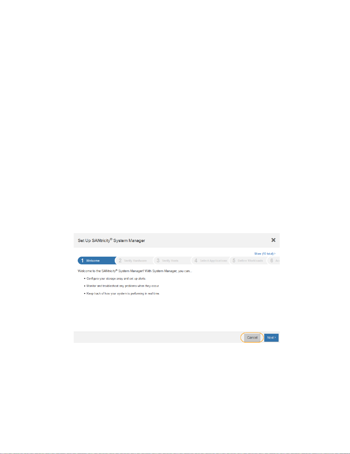
Attention: Do not complete the Set Up wizard for a StorageGRID Webscale appliance.
The Set Up wizard appears.
4. Click Cancel to close the wizard.
Do not complete the Set Up wizard for a StorageGRID Webscale appliance.
The SANtricity System Manager home page appears.
Page 37

Configuring the hardware |
37
Related tasks
Setting the IP addresses for the E2800 controllers
Related references
Web browser requirements
on page 15
on page 37
Setting the IP addresses for the E2800 controllers
Management port 1 on each E2800 controller connects the appliance to the management network for
SANtricity System Manager. You must set a static IP address for each E2800 controller to ensure that
you do not lose your management connection to the hardware and the controller firmware in the
E2860 controller shelf.
About this task
The DHCP server assigns a new IP address whenever you disconnect and reconnect the Ethernet
cable or power cycle the appliance. This process occurs until you configure a static IP address for the
controller.
Steps
1. From SANtricity System Manager, click the Hardware tab.
2. If the graphic shows the drives, click Show back of shelf.
3. From the image of the appliance, click Controller B.
4. From the controller's context menu, select Configure management ports.
Page 38

38 | Hardware Installation and Maintenance Guide for SG6000 Appliances
5. For step 1 of the Configure Management Ports wizard, make sure Port P1 is selected, and click
Next.
6. For step 2 of the Configure Management Ports wizard, configure the network settings for port 1
on controller B.
a. From the Speed and duplex mode drop-down list, make sure Auto-negotiate is selected.
You must also make sure the Ethernet switch for the management network is set to
autonegotiate. Connectivity issues might occur if automatic negotiation is selected in
SANtricity System Manager but not set for the Ethernet switch.
b. Depending on your network configuration, select Enable IPv4, Enable IPv6, or both.
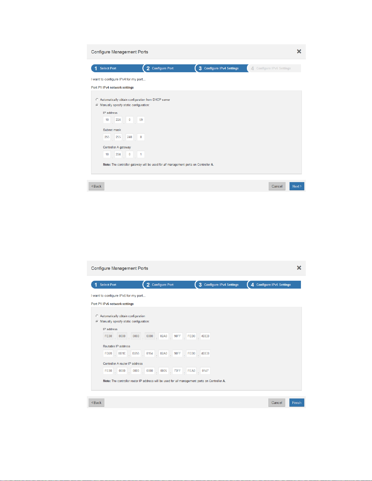
7. If you selected Enable IPv4:
a. Click Next.
b. Make sure Manually specify static configuration is selected.
c. Change the IP address of port 1 to a routable management IP address, subnet mask, and
gateway.
Page 39
Configuring the hardware |
39
8. If you selected Enable IPv6:
a. Click Next.
b. Make sure Manually specify static configuration is selected.
c. Enter an IP address, routable IP address, and router IP address.
9. Click Finish.
10. Repeat step
3
through step 9 to configure the IP address of management port 1 on controller A.
Page 40

| Hardware Installation and Maintenance Guide for SG6000 Appliances
40
11. Disconnect your laptop from the E2800 controller. Then, connect an Ethernet cable to
management port 1 (labeled P1) on each E2800 controller, and connect the other end to your
network.
Do not use management port 2 (labeled P2). This port is reserved for NetApp technical support.
12. Reconnect to SANtricity System Manager, but use the new static IP address for either controller
A or B as the URL:
https://E2800_Controller_IP
Setting up SANtricity System Manager
After accessing SANtricity System Manager, you can use it to configure hardware settings. Typically,
you configure these settings before deploying the appliance as a Storage Node in a StorageGRID
Webscale grid.
About this task
You use SANtricity System Manager to configure the following settings:
• Email alerts, SNMP alerts, or syslog alerts for the components in the E2860 controller shelf
• AutoSupport settings for the components in the E2860 controller shelf
• Drive Security keys, which are needed to unlock secured drives (this step is required if the Drive
Security feature is enabled)
• Administrator password for accessing SANtricity System Manager
Steps
1. Open a web browser on a management client, and enter the URL for SANtricity System Manager:
https://E2800_Controller_IP
The log in page for SANtricity System Manager appears.
2. Enter the administrator password.
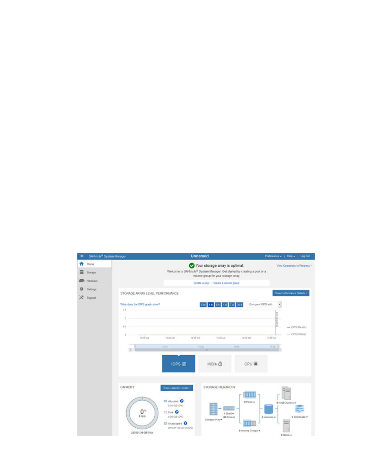
3. Click Cancel to close the Set Up wizard and to display the SANtricity System Manager home
page.
4. Configure hardware alerts.
a. Select Help to access the online help for SANtricity System Manager.
b. Use the Settings > Alerts section of the online help to learn about alerts.
c. Follow the “How To” instructions to set up email alerts, SNMP alerts, or syslog alerts.
5. Manage AutoSupport for the components in the E2860 controller shelf.
a. Select Help to access the online help for SANtricity System Manager.
b. Use the Support > Support Center section of the online help to learn about the AutoSupport
feature.
c. Follow the “How To” instructions to manage AutoSupport.
6. If the Drive Security feature is enabled for the appliance, create and manage the security key.
a. Select Help to access the online help for SANtricity System Manager.
b. Use the Settings > System > Security key management section of the online help to learn
about Drive Security.
Page 41
Configuring the hardware |
c. Follow the “How To” instructions to create and manage the security key.
7. Optionally, change the administrator password.
a. Select Help to access the online help for SANtricity System Manager.
b. Use the Home > Storage array administration section of the online help to learn about the
administrator password.
c. Follow the “How To” instructions to change the password.
Reviewing the hardware status in SANtricity System Manager
You can use SANtricity System Manager to monitor and manage the individual hardware
components in the E2860 controller shelf and to review hardware diagnostic and environmental
information, such as component temperatures, as well as issues related to the drives.
Steps
Open a web browser on a management client, and enter the URL for SANtricity System Manager:
1.
https://E2800_Controller_IP
The log in page for SANtricity System Manager appears.
41
2. Enter the administrator password.
3. Click Cancel to close the Set Up wizard and to display the SANtricity System Manager home
page.
The SANtricity System Manager home page appears. In SANtricity System Manager, the
controller shelf is referred to as a
storage array
.
Page 42

| Hardware Installation and Maintenance Guide for SG6000 Appliances
42
4. Review the information displayed for appliance hardware and confirm that all hardware
components have a status of Optimal.
a. Click the Hardware tab.
b. Click Show back of shelf.
From the back of the shelf, you can view both E2800 controllers, the battery in each E2800
controller, the two power canisters, and the two fan canisters. You can also view component
temperatures.
c. To see the settings for each E2800 controller, select the controller, and select View settings
from the context menu.
d. To see the settings for other components in the back of the shelf, select the component you
want to view.
e. Click Show front of shelf, and select the component you want to view.
From the front of the shelf, you can view the drives and the five drive drawers for the E2860
controller shelf.
If the status of any component is Needs Attention, follow the steps in the Recovery Guru to
resolve the issue or contact technical support.
Configuring StorageGRID Webscale connections
Before you can deploy a StorageGRID Webscale appliance as a Storage Node in a StorageGRID
Webscale grid, you must configure the connections between the appliance and the networks you plan
to use. You can configure networking by browsing to the StorageGRID Appliance Installer, which is
included on the SG6000-CN controller (the compute controller).
Steps
1. Accessing the StorageGRID Appliance Installer on page 43
2. Configuring network links on page 44
3. Configuring StorageGRID Webscale IP addresses on page 48
4. Verifying network connections on page 51
Page 43
Configuring the hardware |
Accessing the StorageGRID Appliance Installer
You must access the StorageGRID Appliance Installer to configure the connections between the
appliance and the three StorageGRID Webscale networks: the Grid Network, the Admin Network
(optional), and the Client Network (optional).
Before you begin
• You are using any management client that can connect to the StorageGRID Webscale Admin
Network, or you have a service laptop.
• The client or service laptop has a supported web browser.
• The SG6000-CN controller is connected to all of the StorageGRID Webscale networks you plan
to use.
• You know the IP address, gateway, and subnet for the SG6000-CN controller on these networks.
• You have configured the network switches you plan to use.
About this task
To initially access the StorageGRID Appliance Installer, you can use the DHCP-assigned IP address
for the Admin Network port on the SG6000-CN controller (assuming the controller is connected to
the Admin Network), or you can connect a service laptop directly to the SG6000-CN controller.
43
Steps
1. If possible, use the DHCP address for the Admin Network port on the SG6000-CN controller to
access the StorageGRID Appliance Installer.
a. Locate the MAC address label on the front of the SG6000-CN controller, and determine the
MAC address for the Admin Network port.
The MAC address label lists the MAC address for the BMC management port.
To determine the MAC address for the Admin Network port, you must add 2 to the
hexadecimal number on the label. For example, if the MAC address on the label ends in 09,
the MAC address for the Admin Port would end in 0B. If the MAC address on the label ends
in (y)FF, the MAC address for the Admin Port would end in (y+1)01. You can easily make
this calculation by opening Calculator in Windows, setting it to Programmer mode, selecting
Hex, typing the MAC address, then typing + 2 =.
b. Provide the MAC address to your network administrator, so they can look up the DHCP
address for the appliance on the Admin Network.
c. From the client, enter this URL for the StorageGRID Appliance Installer:
http://SG6000-CN_Controller_IP:8080
For SG6000-CN_Controller_IP, use the DHCP address.
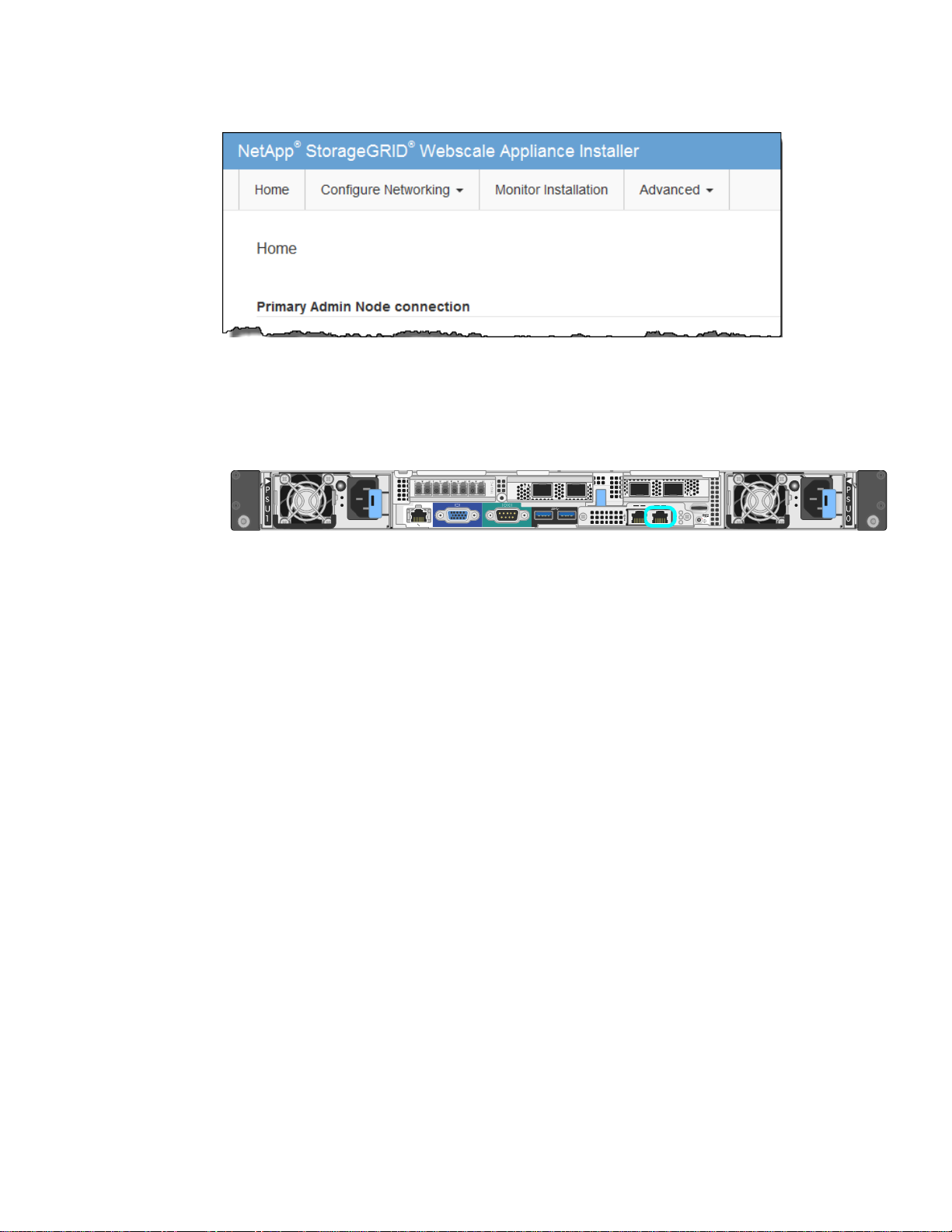
The StorageGRID Appliance Installer Home page appears. The information and messages
shown when you first access this page depend on how your appliance is currently connected to
StorageGRID Webscale networks. Error messages might appear that will be resolved in later
steps.
Page 44
| Hardware Installation and Maintenance Guide for SG6000 Appliances
44
If you cannot obtain an IP address using DHCP, you can use a link-local connection.
2.
a. Connect a service laptop directly to the rightmost RJ-45 port on the SG6000-CN controller,
using an Ethernet cable.
b. Open a web browser on the service laptop.
c. Enter this URL for the StorageGRID Appliance Installer:
http://169.254.0.1:8080
The StorageGRID Appliance Installer Home page appears. The information and messages
shown when you first access this page depend on how your appliance is currently connected.
Note: If you cannot access the Home page over a link-local connection, configure the
service laptop IP address as 169.254.0.2, and try again.
3. Review any messages displayed on the Home page and configure the link configuration and the
IP configuration, as required.
Related references
Web browser requirements
on page 15
Configuring network links
If you do not want to use the default configuration for the four 10/25-GbE ports on the SG6000-CN
controller, you must configure the link settings. These ports are used to connect the appliance to the
Grid Network and the optional Client Network. You can set the link speed as well as the port and
network bond modes.
Before you begin
If you plan to use the 25-GbE link speed:
• You are using SFP28 TwinAx cables, or you have installed SFP28 transceivers in the 10/25-GbE
ports you plan to use.
• You have connected the 10/25-GbE ports to switches that can support these features.
• You understand how to configure the switches to use this higher speed.
Page 45
Configuring the hardware |
If you plan to use Aggregate port bond mode, LACP network bond mode, or VLAN tagging:
• You have connected the 10/25-GbE ports on the appliance to switches that can support VLAN
and LACP.
• If multiple switches are participating in the LACP bond, the switches support multi-chassis link
aggregation groups (MLAG), or equivalent.
• You understand how to configure the switches to use VLAN, LACP, and MLAG or equivalent.
• You know the unique VLAN tag to use for each network. This VLAN tag will be added to each
network packet to ensure that network traffic is routed to the correct network.
About this task
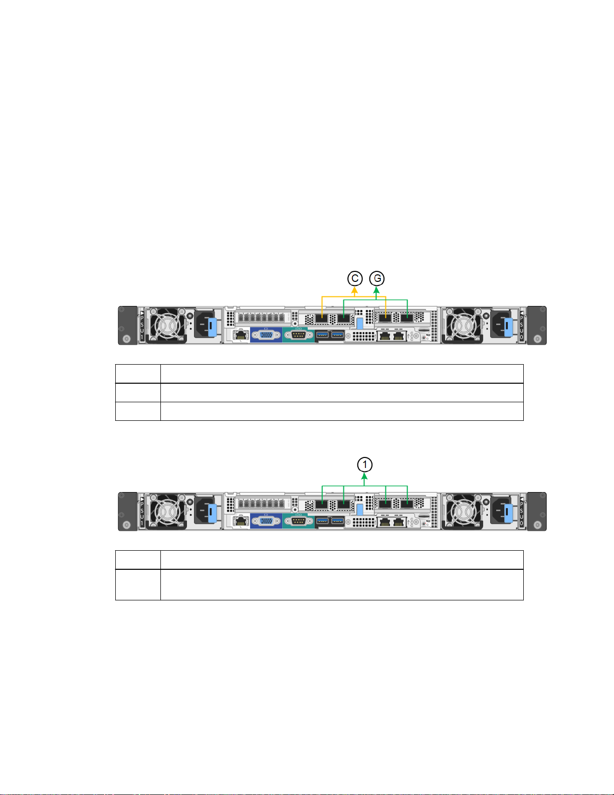
This figure shows how the four 10/25-GbE ports are bonded in fixed port bond mode (default
configuration).
45
Callout
Which ports are bonded
C Ports 1 and 3 are bonded together for the Client Network, if this network is used.
G Ports 2 and 4 are bonded together for the Grid Network.
This figure shows how the four 10/25-GbE ports are bonded in aggregate port bond mode.
Callout
Which ports are bonded
1 All four ports are grouped in a single LACP bond, allowing all ports to be used for Grid
Network and Client Network traffic.
The table summarizes the options for configuring the four 10/25-GbE ports. The default settings are
shown in bold. You only need to configure the settings on the Link Configuration page if you want to
use a non-default setting.
Page 46

| Hardware Installation and Maintenance Guide for SG6000 Appliances
46
Port bond
mode
Fixed
(default)
Network bond
mode
ActiveBackup
(default)
LACP
(802.3ad)
Client Network disabled
(default)
• Ports 2 and 4 use an
active-backup bond
for the Grid Network.
• Ports 1 and 3 are not
used.
• A VLAN tag is
optional.
• Ports 2 and 4 use an
LACP bond for the
Grid Network.
• Ports 1 and 3 are not
used.
• A VLAN tag is
optional.
Client Network enabled
• Ports 2 and 4 use an activebackup bond for the Grid
Network.
• Ports 1 and 3 use an activebackup bond for the Client
Network.
• VLAN tags can be specified
for both networks for the
convenience of the network
administrator.
• Ports 2 and 4 use an LACP
bond for the Grid Network.
• Ports 1 and 3 use an LACP
bond for the Client Network.
• VLAN tags can be specified
for both networks for the
convenience of the network
administrator.
Aggregate LACP
(802.3ad) only
• Ports 1-4 use a single
LACP bond for the
Grid Network.
• A single VLAN tag
identifies Grid Network
packets.
• Ports 1-4 use a single LACP
bond for the Grid Network
and the Client Network.
• Two VLAN tags allow Grid
Network packets to be
segregated from Client
Network packets.
See “10/25-GbE port connections for the SG6000-CN controller” for more information about port
bond and network bond modes.
Steps
1. From the menu bar of the StorageGRID Appliance Installer, click Configure Networking > Link
Configuration.
The Network Link Configuration page appears. The first time you access this page:
• Link Speed is set to 10GbE.
• Port bond mode is set to Fixed.
• Network bond mode is set to Active-Backup.
• The Admin Network is enabled.
• The Client Network is disabled.
Page 47

Configuring the hardware |
47
2. If you plan to use the 25-GbE link speed for the 10/25 GbE ports, select 25GbE from the Link
speed drop-down list.
The network switches you are using for the Grid Network and the Client Network must also
support and be configured for this speed. You must use SFP28 TwinAx cables or optical cables
and SFP28 transceivers.
3. Enable or disable the StorageGRID Webscale networks you plan to use.
The Grid Network is required. You cannot disable this network.
a. If the appliance is not connected to the Admin Network, unselect the Enable network check
box for the Admin Network.
b. If the appliance is connected to the Client Network, select the Enable network check box for
the Client Network.
The Client Network settings for the 10/25-GbE ports are now shown.
4. Refer to the table, and configure the port bond mode and the network bond mode.
This screen shot shows Aggregate and LACP selected for the Grid and the Client networks. You
must specify a unique VLAN tag for each network. You can select values between 0 and 4095.
Page 48

| Hardware Installation and Maintenance Guide for SG6000 Appliances
48
5. When you are satisfied with your selections, click Save.
Note: You might lose your connection if you made changes to the network or link you are
connected through. If you are not reconnected within 1 minute, re-enter the URL for the
StorageGRID Appliance Installer using one of the other IP addresses assigned to the appliance:
http://SG6000-CN_Controller_IP:8080
Related concepts
10/25-GbE port connections for the SG6000-CN controller
on page 16
Configuring StorageGRID Webscale IP addresses
You use the StorageGRID Appliance Installer to configure the IP addresses and routing information
used for the appliance Storage Node on the StorageGRID Webscale Grid, Admin, and Client
Networks.
About this task
You must either assign a static IP for the appliance on each connected network or assign a permanent
lease for the address on the DHCP server.
Note: If the virtual nodes in your grid are deployed on VMware, you must use a static IP address
for the appliance on the Grid Network.
Page 49

Configuring the hardware |
Additionally, if you want to change the link configuration of a StorageGRID Webscale appliance, see
the instructions for changing the link configuration of the SG6000-CN controller.
Steps
1. From the menu bar of the StorageGRID Appliance Installer, click Configure Networking > IP
Configuration.
The IP Configuration page appears. This example shows the Grid Network section of the page
with IP Assignment set to DHCP.
49
2. Configure the Grid Network.
a. If you plan to use a static IP address for the appliance on the Grid Network, select Static.
b. Enter the static IPv4 address, using CIDR notation.
c. Enter the gateway.
If your network does not have a gateway, re-enter the same static IPv4 address.
d. Click Save.
When the IP address changes, the gateway and list of subnets might also change.
If you are using the DHCP address for the Grid Network to access the StorageGRID
Appliance Installer, your web browser should be automatically redirected to the new IP
address. If you lose your connection, re-enter the URL but use the new static IP address:
https://SG6000-CN_Controller_IP:8080
e. Confirm that the list of Grid Network subnets is correct.
If you have multiple grid subnets, the Grid Network gateway is required. All grid subnets
specified must be reachable through this gateway. These Grid Network subnets must also be
defined in the Grid Network Subnet List on the primary Admin Node when you start
StorageGRID Webscale installation.
Note: The default route is not listed. If the Client Network is not enabled, the default route
will use the Grid Network gateway.
To add a subnet, click the insert icon
•
to the right of the last entry.
• To remove an unused subnet, click the delete icon
.
Page 50
| Hardware Installation and Maintenance Guide for SG6000 Appliances
50
f. Click Save.
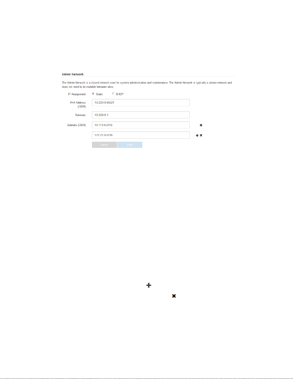
3. Configure the Admin Network.
This section of the page appears if the Admin Network is enabled on the Link Configuration
page.
When you configure the Admin Network, you specify the IP address, gateway, and subnets used
for Management Port 1 on the controller. Management Port 1 is the left of the two 1-GbE RJ45
ports on the right end of the controller.
a. If you plan to use a static IP address for the appliance on the Admin Network, select Static.
b. Enter the static IPv4 address, using CIDR notation.
c. Enter the gateway.
If your network does not have a gateway, re-enter the same static IPv4 address.
d. Click Save.
If you are using the DHCP address for the Admin Network to access the StorageGRID
Appliance Installer, your web browser should be automatically redirected to the new IP
address. If you lose your connection, re-enter the URL but use the new static IP address:
https://SG6000-CN_Controller_IP:8080
e. Confirm that the list of Admin Network subnets is correct.
You must verify that all subnets can be reached using the gateway provided above.
Note: The default route cannot be made to use the Admin Network gateway.
To add a subnet, click the insert icon
•
• To remove an unused subnet, click the delete icon
to the right of the last entry.
.
f. Click Save.
4. Configure the Client Network.
This section of the page appears if the Client Network is enabled on the Link Configuration page.
Page 51
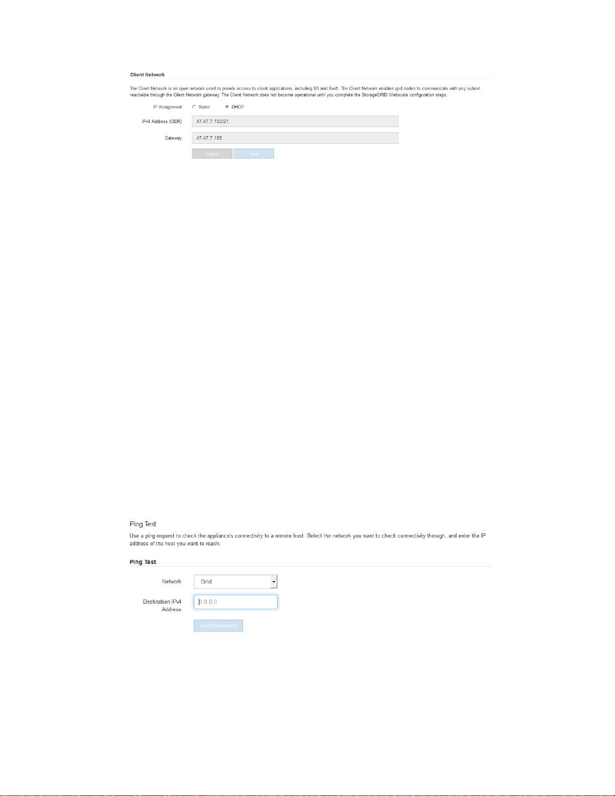
Configuring the hardware |
a. If you plan to use a static IP address for the appliance on the Client Network, select Static.
b. Enter the static IPv4 address, using CIDR notation.
c. Click Save.
d. Confirm that the IP address for the Client Network gateway is correct.
Note: If the Client Network is is enabled, the default route is displayed. The default route
uses the Client Network gateway and cannot be moved to another interface while the Client
Network is enabled.
e. Click Save.
51
Related tasks
Changing the link configuration of the SG6000-CN controller
on page 76
Verifying network connections
You should confirm you can access the StorageGRID Webscale networks you are using from the
appliance. To validate routing through network gateways, you should test connectivity between the
StorageGRID Appliance Installer and IP addresses on different subnets.
Steps
1. From the menu bar of the StorageGRID Appliance Installer, click Configure Networking > Ping
Test.
The Ping Test page appears.
2. From the Network drop-down box, select the network you want to test: Grid, Admin, or Client.
3. Enter the IPv4 address for a host on that network.
For example, you might want to ping the gateway on the network or the primary Admin Node.
4. Click Test Connectivity.
If the network connection is valid, the “Ping test passed” message appears, with the ping
command output listed.
Page 52

| Hardware Installation and Maintenance Guide for SG6000 Appliances
52
Configuring the BMC interface
The user interface for the baseboard management controller (BMC) on the SG6000-CN controller
provides status information about the hardware and allows you to configure SNMP settings and other
options for the SG6000-CN controller.
Steps
1. Setting the IP address for the BMC management port on page 52
2. Accessing the BMC interface and changing the root password on page 54
3. Configuring SNMP settings for the SG6000-CN controller on page 55
Setting the IP address for the BMC management port
Before you can access the BMC interface, you must configure the IP address for the BMC
management port on the SG6000-CN controller.
Before you begin
• You are using any management client that can connect to a StorageGRID Webscale network.
• The client has a supported web browser.
• The BMC management port is connected to the management network you plan to use.
Steps
1. From the client, enter the URL for the StorageGRID Appliance Installer:
http://SG6000-CN_Controller_IP:8080
Page 53

Configuring the hardware |
For SG6000-CN_Controller_IP, use the IP address for the appliance on any StorageGRID
Webscale network.
The StorageGRID Appliance Installer Home page appears.
2. Select Advanced > BMC Configuration.
The Baseboard Management Controller Configuration page appears.
Make a note of the IPv4 address that is automatically displayed.
3.
DHCP is the default method for assigning an IP address to this port.
53
Note: It might take a few minutes for the DHCP values to appear.
4. Optionally, set a static IP address for the BMC management port.
Note: You should either assign a static IP for the BMC management port or assign a permanent
lease for the address on the DHCP server.
a. Select Static.
b. Enter the IPv4 address, using CIDR notation.
c. Enter the default gateway.
Page 54
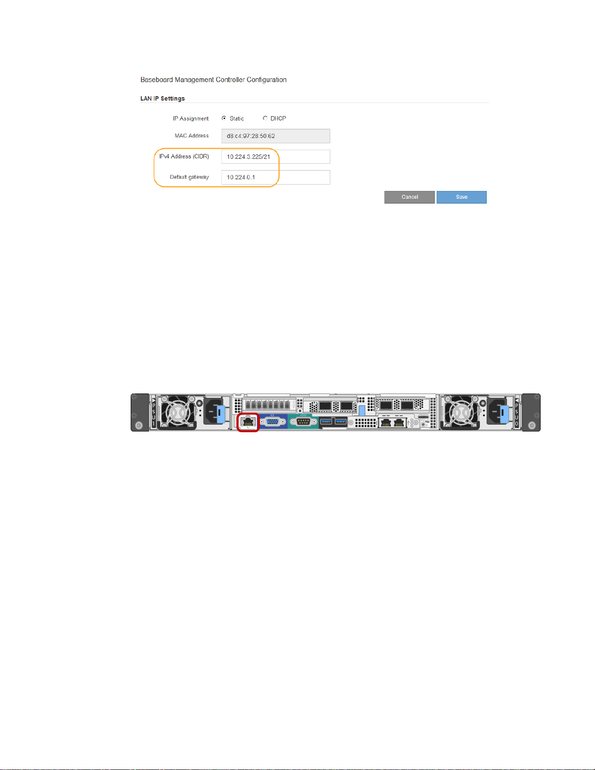
| Hardware Installation and Maintenance Guide for SG6000 Appliances
54
d.
Click Save.
It might take a few minutes for your changes to be applied.
Accessing the BMC interface and changing the root password
You can access the BMC interface on the SG6000-CN controller using the DHCP or static IP address
for the BMC management port. Initially, you access the BMC as “root” and with a default password.
For security, you must change the password for the root user after you first sign in.
Before you begin
• The BMC management port on the SG6000-CN controller is connected to the management
network you plan to use.
• The management client is using a supported web browser.
Steps
1. Enter the URL for the BMC interface:
https://BMC_Port_IP
For BMC_Port_IP, use the DHCP or static IP address for the BMC management port.
The BMC sign-in page appears.
2. Enter the root username and default password:
root
calvin
Page 55

Click Sign me in
3.
The BMC dashboard appears.
Configuring the hardware |
55
4. For security, immediately create your own password for the root account.
a. Select Settings > User Management.
b. Select the root account.
c. Enter and confirm the new password, and click Save.
5. Optionally, create other users by selecting Settings > User Management and clicking on any
“disabled” user.
Configuring SNMP settings for the SG6000-CN controller
If you are familiar with configuring SNMP for hardware, you can use the BMC interface to configure
the SNMP settings for the SG6000-CN controller. You can provide secure community strings, enable
SNMP Trap, and specify up to five SNMP destinations.
Before you begin
• You know how to access the BMC dashboard.
• You have experience in configuring SNMP settings for SNMPv1-v2c equipment.
Page 56

| Hardware Installation and Maintenance Guide for SG6000 Appliances
56
Steps
1. From the BMC dashboard, select Settings > SNMP Settings.
2. On the SNMP Settings page, select the Enable SNMP V1/V2 checkbox, and provide a Read-
Only Community String and a Read-Write Community String.
The Read-Only Community String is like a user ID or password. You should change this value to
prevent intruders from getting information about your network setup. The Read-Write
Community String protects the device against unauthorized changes.
3. Optionally, select Enable Trap, and enter the required information.
Enable traps if you want the SG6000-CN controller to send immediate notifications to an SNMP
console when it is in an unusual state. Traps might indicate link up/down conditions, temperatures
exceeding certain thresholds, or high traffic.
4. Optionally, click Send Test Trap to test your settings.
5. If the settings are correct, click Save.
Optional: Changing to RAID6 mode
You can change the volume configuration from its default and recommended setting, Dynamic Disk
Pools (DDP), to RAID6. You can only change the mode before deploying the appliance Storage
Node.
Before you begin
• You are using any client that can connect to StorageGRID Webscale.
• The client has a supported web browser.
About this task
Before deploying the SG6060 appliance as a Storage Node, you can choose from two volume
configuration options:
• Dynamic Disk Pools (DDP) – This is the default and recommended setting. DDP is an enhanced
hardware data protection scheme that delivers better system performance, reduced rebuild times
after drive failures, and ease of management.
• RAID6 – This is a hardware protection scheme that uses parity stripes on each disk, and allows
for two disk failures within the RAID set before any data is lost.
Attention: Using RAID6 is not recommended for most StorageGRID Webscale environments.
Although RAID6 can increase storage efficiency to 88% (compared to 80% for DDP), DDP
mode provides more efficient recovery from drive failures.
Attention: If any volumes have already been configured or if StorageGRID Webscale was
previously installed, changing the RAID mode causes the volumes to be removed and replaced.
Any data on those volumes will be lost.
Steps
1. Access the StorageGRID Appliance Installer:
http://SG6000-CN_Controller_IP:8080
SG6000-CN_Controller_IP is the IP address of the SG6000-CN controller on any of the three
StorageGRID Webscale networks.
Page 57
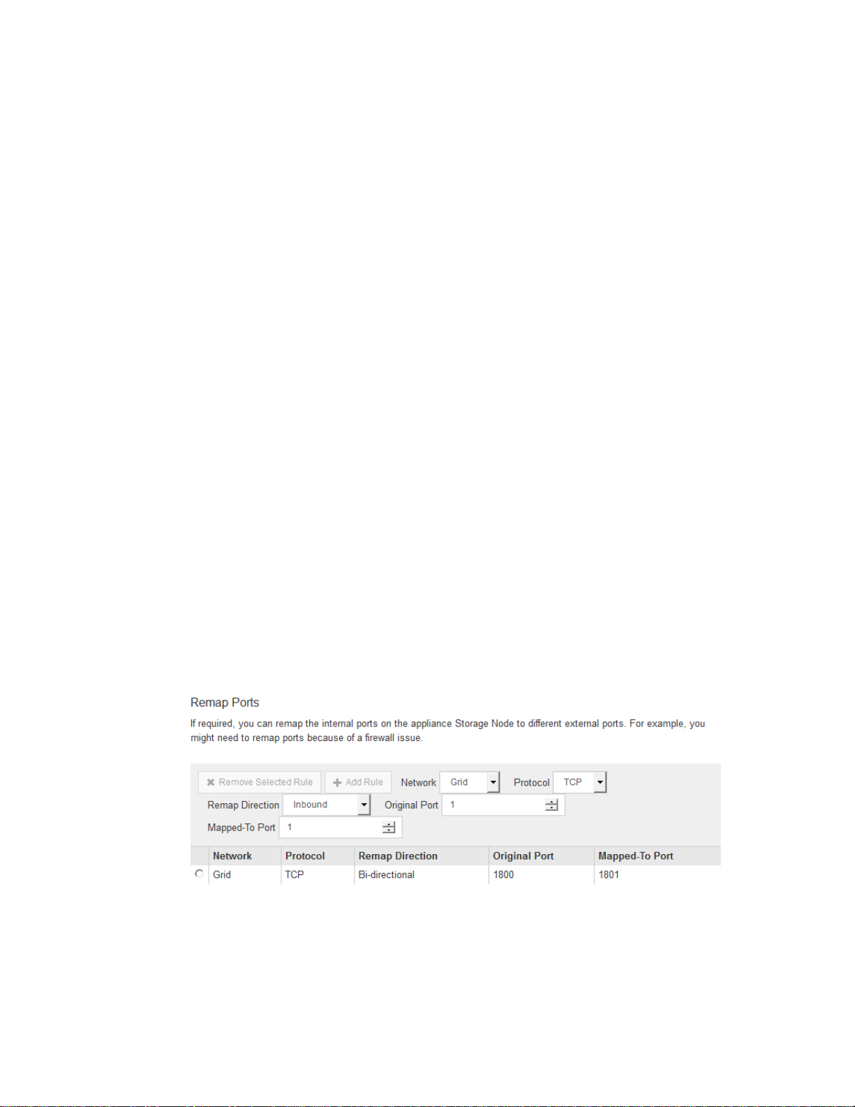
Configuring the hardware |
2. From the menu bar, select Advanced > RAID Mode.
3. On the Configure RAID Mode page, select RAID6 from the Mode drop-down list.
4. Click Save.
Optional: Remapping network ports for the appliance
You might need to remap the internal ports on the appliance Storage Node to different external ports.
For example, you might need to remap ports because of a firewall issue.
Before you begin
You have previously accessed the StorageGRID Appliance Installer.
Steps
From the menu bar of the StorageGRID Appliance Installer, click Configure Networking >
1.
Remap Ports.
The Remap Port page appears.
2. From the Network drop-down box, select the network for the port you want to remap: Grid,
Admin, or Client.
57
3. From the Protocol drop-down box, select the IP protocol: TCP or UDP.
4. From the Remap Direction drop-down box, select which traffic direction you want to remap for
this port: Inbound, Outbound, or Bi-directional.
5. For Original Port, enter the number of the port you want to remap.
6. For Mapped-To Port, enter the number of the port you want to use instead.
7. Click Add Rule.
The new port mapping is added to the table, and the remapping takes effect immediately.
8. To remove a port mapping, select the radio button for the rule you want to remove, and click
Remove Selected Rule.
Page 58

58
Where to go next
After installing and configuring the StorageGRID Webscale appliance, you can deploy it as a Storage
Node in a StorageGRID Webscale grid.
• To deploy an appliance Storage Node in a new StorageGRID Webscale grid, see the installation
instructions for your platform.
• To add an appliance Storage Node to an existing StorageGRID Webscale grid, see information
about expanding a StorageGRID Webscale grid.
• To deploy an appliance Storage Node as part of a recovery operation, see information about
recovery and maintenance.
Related information
VMware installation
Red Hat Enterprise Linux or CentOS installation
Ubuntu or Debian installation
Expanding a StorageGRID Webscale grid
Recovery and maintenance
Page 59
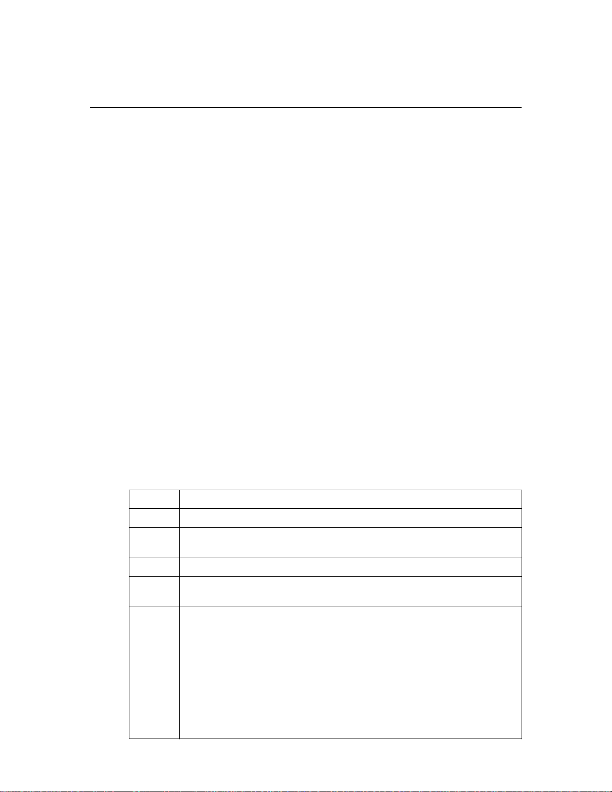
Troubleshooting the hardware installation
If you encounter issues during the installation, you might find it helpful to review troubleshooting
information related to hardware setup and connectivity issues.
Related tasks
59
Hardware setup appears to hang
Related references
Troubleshooting connection issues
on page 62
on page 62
Viewing boot-up codes for the SG6000-CN controller
When you apply power to the appliance, the BMC logs a series of boot-up codes for the SG6000-CN
controller. If you have experience deploying and using KVM applications, you can view these codes
on a graphical console by launching a KVM (Java) application from the BMC interface.
Before you begin
• You know how to access the BMC dashboard.
• You have experience deploying and using KVM applications.
Steps
1. From the BMC dashboard, select Remote Control.
2. Launch the KVM Java application, which you can use to access the graphical console for the
controller.
3. Review the boot-up codes, which are displayed in the order listed.
Code
HI The master boot script has started.
HP The system is checking to see if the 10/25-GbE controller firmware needs to be
RB The system is rebooting after applying firmware updates.
FP The hardware subsystem firmware update checks have been completed. Inter-
HE The system is awaiting connectivity with the E2800 controllers and synchronizing
Indicates
updated.
controller communication services are starting.
with the SANtricity operating system.
Note: If the boot-up procedure does not progress past this stage:
a. Confirm that the four interconnect cables between the SG6000-CN
controller and the two E2800 controllers are securely connected.
b. As required, replace one or more of the cables, and try again.
c. If this does not resolve the issue, contact technical support.
Page 60

60 | Hardware Installation and Maintenance Guide for SG6000 Appliances
Code Indicates
HC The system is checking for existing StorageGRID Webscale installation data.
HO The StorageGRID Appliance Installer is running.
HA StorageGRID Webscale is running.
Viewing error codes for the SG6000-CN controller
If a hardware error occurs when the SG6000-CN controller is booting up, the BMC logs an error
code. As required, you can view these error codes using the BMC interface, and then work with
technical support to resolve the issue.
Before you begin
• You know how to access the BMC dashboard.
Steps
From the BMC dashboard, select BIOS POST Code.
1.
2. Review the information displayed for Current Code and the Previous Code.
If any of the following error codes are shown, work with technical support to resolve the issue.
Code
0x0E Microcode not found
0x0F Microcode not loaded
0x50 Memory initialization error. Invalid memory type or incompatible
0x51 Memory initialization error. SPD reading has failed.
0x52 Memory initialization error. Invalid memory size or memory
0x53 Memory initialization error. No usable memory detected.
0x54 Unspecified memory initialization error
0x55 Memory not installed
0x56 Invalid CPU type or speed
0x57 CPU mismatch
0x58 CPU self-test failed, or possible CPU cache error
0x59 CPU micro-code is not found, or micro-code update failed
Indicates
memory speed.
modules do not match.
0x5A Internal CPU error
0x5B Reset PPI is not available
0x5C PEI phase BMC self-test failure
0xD0 CPU initialization error
0xD1 North bridge initialization error
0xD2 South bridge initialization error
Page 61

Troubleshooting the hardware installation | 61
Code Indicates
0xD3 Some architectural protocols are not available
0xD4 PCI resource allocation error. Out of resources.
0xD5 No space for legacy option ROM
0xD6 No console output devices are found
0xD7 No console input devices are found
0xD8 Invalid password
0xD9 Error loading boot option (LoadImage returned error)
0xDA Boot option failed (StartImage returned error)
0xDB Flash update failed
0xDC Reset protocol is not available
0xDD DXE phase BMC self-test failure
0xE8 MRC: ERR_NO_MEMORY
0xE9 MRC: ERR_LT_LOCK
0xEA MRC: ERR_DDR_INIT
0xEB MRC: ERR_MEM_TEST
0xEC MRC: ERR_VENDOR_SPECIFIC
0xED MRC: ERR_DIMM_COMPAT
0xEE MRC: ERR_MRC_COMPATIBILITY
0xEF MRC: ERR_MRC_STRUCT
0xF0 MRC: ERR_SET_VDD
0xF1 MRC: ERR_IOT_MEM_BUFFER
0xF2 MRC: ERR_RC_INTERNAL
0xF3 MRC: ERR_INVALID_REG_ACCESS
0xF4 MRC: ERR_SET_MC_FREQ
0xF5 MRC: ERR_READ_MC_FREQ
0x70 MRC: ERR_DIMM_CHANNEL
0x74 MRC: ERR_BIST_CHECK
0xF6 MRC: ERR_SMBUS
0xF7 MRC: ERR_PCU
0xF8 MRC: ERR_NGN
0xF9 MRC: ERR_INTERLEAVE_FAILURE
Page 62

| Hardware Installation and Maintenance Guide for SG6000 Appliances
62
Hardware setup appears to hang
The StorageGRID Appliance Installer might not be available if hardware faults or cabling errors
prevent the E2800 controllers or the SG6000-CN controller from completing their boot-up
processing.
Steps
1. For the E2800 controllers, watch the codes on the seven-segment displays.
While the hardware is initializing during power up, the two seven-segment displays show a
sequence of codes. When the hardware boots successfully, both seven-segment displays show 99.
Review the LEDs on the SG6000-CN controller and the boot-up and error codes displayed in the
2.
BMC.
If you need help resolving an issue, contact technical support.
3.
Related tasks
Viewing boot-up status codes for the E2800 controllers
Viewing boot-up codes for the SG6000-CN controller
Viewing error codes for the SG6000-CN controller
Related references
Viewing status indicators and buttons on the SG6000-CN controller
Related information
on page 32
on page 59
on page 60
on page 33
E5700 and E2800 System Monitoring Guide
Troubleshooting connection issues
If you encounter connection issues during the StorageGRID Webscale appliance installation, you
should perform the corrective action steps listed.
Unable to connect to the appliance
If you cannot connect to the appliance, there might be a network issue, or the hardware installation
might not have been completed successfully.
Steps
1. If you are unable to connect to SANtricity System Manager:
a. Try to ping the appliance using the IP address for either E2800 controller on the management
network for SANtricity System Manager:
ping E2800_Controller_IP
b. If you receive no response from the ping, confirm you are using the correct IP address.
Use the IP address for management port 1 on either E2800 controller.
c. If the IP address is correct, check appliance cabling and the network setup.
If that does not resolve the issue, contact technical support.
Page 63
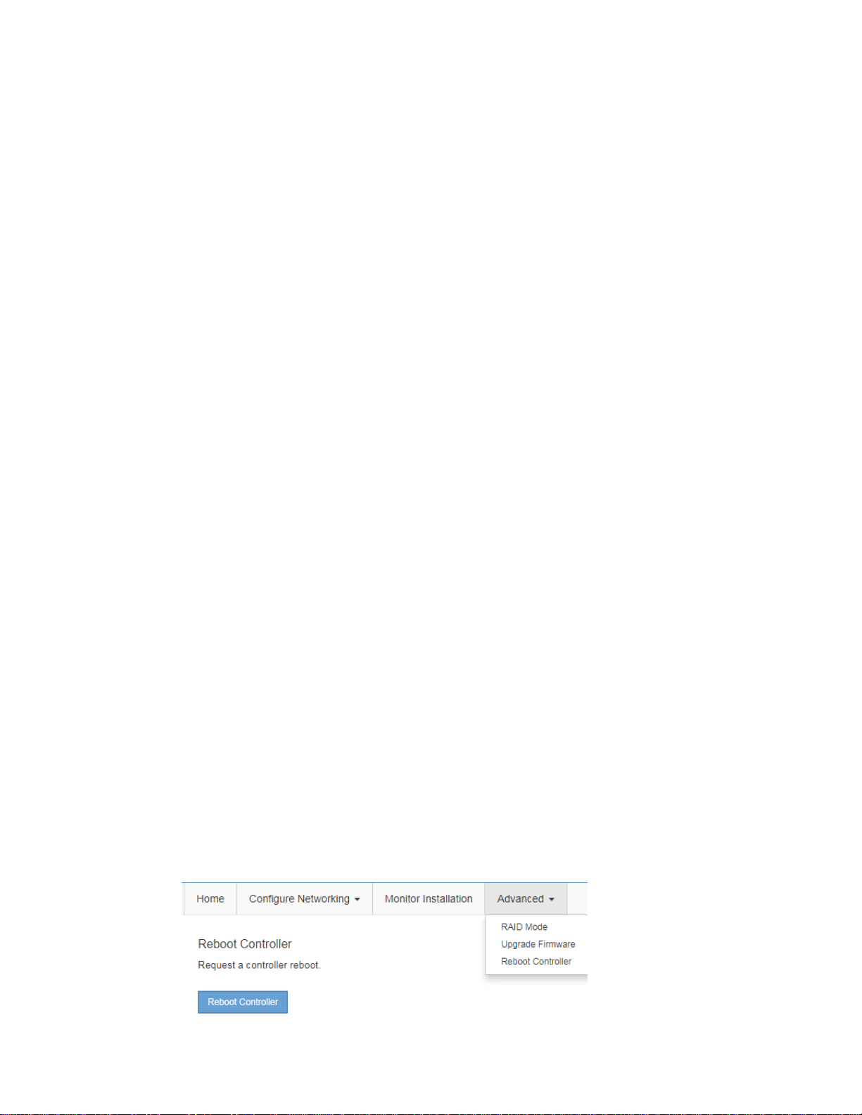
Troubleshooting the hardware installation |
d. If the ping was successful, open a web browser.
e. Enter the URL for SANtricity System Manager:
https://E2800_Controller_IP
The log in page for SANtricity System Manager appears.
2. If you are unable to connect to the SG6000-CN controller:
a. Try to ping the appliance using the IP address for the SG6000-CN controller :
ping SG6000-CN_Controller_IP
b. If you receive no response from the ping, confirm you are using the correct IP address.
You can use the IP address of the appliance on the Grid Network, the Admin Network, or the
Client Network.
c. If the IP address is correct, check appliance cabling, SFP transceivers, and the network setup.
If that does not resolve the issue, contact technical support.
d. If the ping was successful, open a web browser.
e. Enter the URL for the StorageGRID Appliance Installer:
http://SG6000-CN_Controller_IP:8080
63
The Home page appears.
Rebooting the SG6000-CN controller while the StorageGRID Appliance Installer is running
You might need to reboot the SG6000-CN controller while the StorageGRID Appliance Installer is
running. For example, you might need to reboot the controller if the installation fails.
About this task
This procedure only applies when the SG6000-CN controller is running the StorageGRID Appliance
Installer. Once the installation is completed, this step no longer works because the StorageGRID
Appliance Installer is no longer available.
Steps
1. From the menu bar of the StorageGRID Appliance Installer, click Advanced > Reboot
Controller.
The Reboot Controller page appears.
2. Click Reboot Controller.
A confirm dialog box appears.
Page 64

64 | Hardware Installation and Maintenance Guide for SG6000 Appliances
3. Confirm you want to reboot the controller.
The SG6000-CN controller is rebooted.
Page 65

Maintaining the SG6000 appliance
You might need to perform maintenance procedures on the SG6000 appliance. The procedures in this
section assume that the appliance has already been deployed as a Storage Node in a StorageGRID
Webscale grid.
Steps
1. Upgrading SANtricity OS Software on the E2800 controllers on page 65
2. Replacing an E2800 controller on page 67
3. Replacing hardware components in the E2860 controller shelf on page 72
4. Replacing the SG6000-CN controller on page 73
5. Replacing a power supply in the SG6000-CN controller on page 74
6. Changing the link configuration of the SG6000-CN controller on page 76
Upgrading SANtricity OS Software on the E2800 controllers
65
You might need to upgrade the E-Series SANtricity OS Software on the E2800 controllers, if the
controllers are not functioning optimally.
Before you begin
You have contacted technical support and have obtained SANtricity OS Software and NVSRAM files
that are compatible with your StorageGRID Webscale appliance.
Attention: Do not upgrade the SANtricity OS Software or NVSRAM in the E2800 controllers
unless directed to do so by technical support. Without the guidance of technical support, your
StorageGRID Webscale appliance could become inoperable. Contact technical support with any
upgrade-related questions.
About this task
Before you can apply a SANtricityOS Software upgrade, you must place the SG6000-CN controller
into maintenance mode, which interrupts the connection to the E2800 controller. Putting a
StorageGRID Webscale appliance into maintenance mode might make the appliance unavailable for
remote access.
Attention: Do not upgrade the SANtricity OS Software or NVSRAM in the E2800 controllers on
more than one StorageGRID Webscale appliance at a time. Doing so may cause data unavailability,
depending on your deployment model and ILM policies.
Steps
1. If the StorageGRID Webscale appliance is running in a StorageGRID Webscale system, place the
SG6000-CN controller into maintenance mode.
a. From the service laptop, log in to the grid node:
i. Enter the following command: ssh admin@grid_node_IP
ii. Enter the password listed in the Passwords.txt file.
iii. Enter the following command to switch to root: su -
Page 66

| Hardware Installation and Maintenance Guide for SG6000 Appliances
66
iv. Enter the password listed in the Passwords.txt file.
When you are logged in as root, the prompt changes from $ to #.
b. Stop all StorageGRID Webscale services:
service servermanager stop
c. Place the SG6000-CN controller into maintenance mode:
sgamaintenance
The following messages are displayed on the service laptop:
WARNING: All StorageGRID Webscale services on this node will be
shut down.
WARNING: You will have to manually exit maintenance mode before
this node will resume normal operation.
After running this command and waiting a few minutes for the node
to reboot, browse to one of the following URLs to perform any
maintenance actions, then exit maintenance mode:
http://192.168.4.138:8080
http://10.224.4.138:8080
http://47.47.4.138:8080
http://169.254.0.1:8080
Are you sure you want to continue (y/n)?
d. Enter y to continue.
The appliance reboots, which takes two or three minutes to complete.
e. Browse to any of the URLs displayed in the output of the sgamaintenance command to
access the StorageGRID Appliance Installer.
Note: Accessing http://169.254.0.1:8080 requires a direct connection from the
service laptop to the rightmost RJ-45 port on the SG6000-CN controller.
f. Confirm that the appliance is in maintenance mode by noting the maintenance mode message
on the StorageGRID Appliance Installer home page.
2. From a service laptop or management client, access SANtricity System Manager and sign in.
3. Download the new SANtricity OS Software file and NVSRAM file to the management client.
Attention: The NVSRAM is specific to the StorageGRID Webscale appliance. Do not use the
standard NVSRAM download.
4. Follow the instructions in the SANtricity System Manager online help to upgrade the firmware
and NVSRAM.
Note: Activate the upgrade files immediately. Do not defer activation.
5. Once the upgrade operation has completed, return the StorageGRID Webscale appliance to
normal operating mode:
a. From the StorageGRID Appliance Installer, select Advanced > Reboot Controller.
Page 67

Maintaining the SG6000 appliance |
b. Click Reboot Controller.
The appliance reboots and rejoins the grid. This process can take up to 20 minutes.
c. Monitor the status of the upgraded appliance Storage Node in the Grid Manager.
Verify that the appliance returns to the expected status.
Related tasks
67
Accessing SANtricity System Manager
Related information
on page 35
E2800 and E5700 SANtricity Software and Firmware Upgrade Guide
E-Series and SANtricity 11.5 Documentation Center
NetApp Downloads: Software
Replacing an E2800 controller
You might need to replace an E2800 controller if it is not functioning optimally or if it has failed.
Before you begin
• You have a replacement controller with the same part number as the controller you are replacing.
• You have labels to identify each cable that is connected to the controller.
• You have an ESD wristband, or you have taken other antistatic precautions.
• You have a #1 Phillips screwdriver.
• You have the E-Series instructions for replacing a controller in duplex configuration.
Attention: Refer to the E-Series instructions only when directed or if you need more details to
perform a specific step. Do not rely on the E-Series instructions to replace a controller in the
StorageGRID Webscale appliance, because the procedures are not the same.
About this task
You can determine if you have a failed controller in two ways:
• The Recovery Guru in SANtricity System Manager directs you to replace the controller.
• The amber Attention LED on the controller is on, indicating that the controller has a fault.
Attention: If both controllers in the shelf have their Attention LEDs on, contact technical
support for assistance.
Page 68
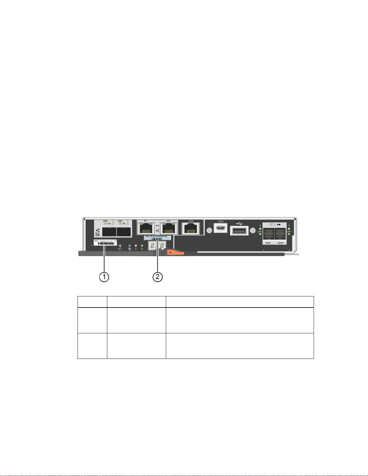
| Hardware Installation and Maintenance Guide for SG6000 Appliances
68
Because the E2860 controller shelf has two E2800 controllers, you can replace one of the controllers
while your appliance is powered on and performing read/write operations, as long as the following
conditions are true:
• The second controller in the shelf has Optimal status.
• The “OK to remove” field in the Details area of the Recovery Guru in SANtricity System
Manager displays Yes, indicating that it is safe to remove this component.
Attention: If the second controller canister in the shelf does not have Optimal status or if the
Recovery Guru indicates that it is not OK to remove the controller canister, contact technical
support.
When you replace a controller, you must remove the battery from the original controller and install it
in the replacement controller.
Note: The E2800 controllers in the appliance do not include host interface cards (HIC).
Steps
Unpack the new controller, and set it on a flat, static-free surface.
1.
Save the packing materials to use when shipping the failed controller.
2. Locate the MAC address and FRU part number labels on the back of the replacement controller.
Label
Label Description
MAC address The MAC address for management port 1 (“P1”). If you
1
used DHCP to obtain the original controller's IP address,
you will need this address to connect to the new controller.
FRU part number The FRU part number. This number must match the
2
replacement part number for the currently installed
controller.
3. Prepare to remove the controller.
You use SANtricity System Manager to perform these steps. As needed for additional details,
reference the E-Series instructions for replacing the E2800 controller.
a. Confirm that the replacement part number for the failed controller is the same as the FRU part
number for the replacement controller.
When a controller has a fault and needs to be replaced, the replacement part number is
displayed in the Details area of the Recovery Guru. If you need to find this number manually,
you can look on the Base tab for the controller.
Attention: Possible loss of data access – If the two part numbers are not the same, do not
attempt this procedure.
Page 69
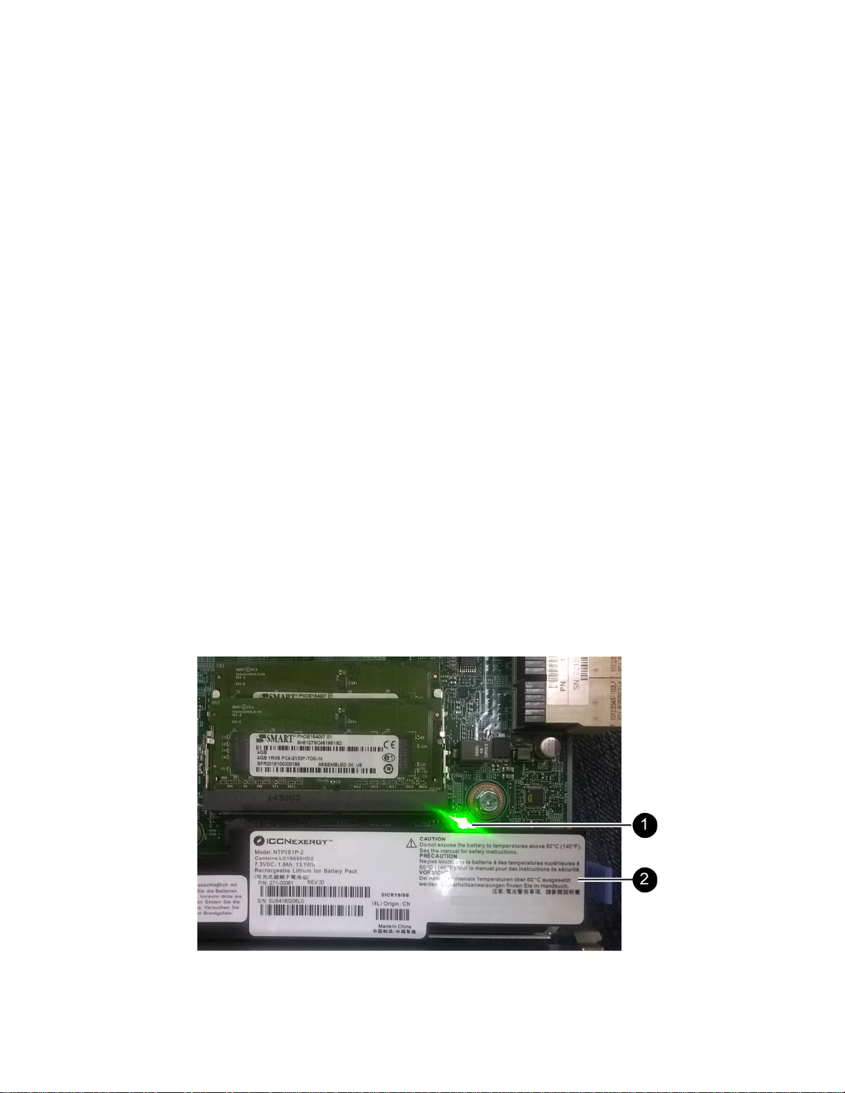
Maintaining the SG6000 appliance |
b. Back up the configuration database.
If a problem occurs when you remove a controller, you can use the saved file to restore your
configuration.
c. Collect support data for the appliance.
Note: Collecting support data before and after replacing a component ensures you can send
a full set of logs to technical support in case the replacement does not resolve the problem.
d. Take the controller you plan to replace offline.
Remove the controller from the appliance:
4.
a. Put on an ESD wristband or take other antistatic precautions.
b. Label the cables and then disconnect the cables and SFPs.
Attention: To prevent degraded performance, do not twist, fold, pinch, or step on the
cables.
c. Release the controller from the appliance by squeezing the latch on the cam handle until it
releases, and then open the cam handle to the right.
d. Using two hands and the cam handle, slide the controller out of the appliance.
69
Attention: Always use two hands to support the weight of the controller.
e. Place the controller on a flat, static-free surface with the removable cover facing up.
f. Remove the cover by pressing down on the button and sliding the cover off.
5. Remove the battery from the failed controller, and install it into the replacement controller:
a. Confirm that the green LED inside the controller (between the battery and the DIMMs) is off.
If this green LED is on, the controller is still using battery power. You must wait for this LED
to go off before removing any components.
Page 70
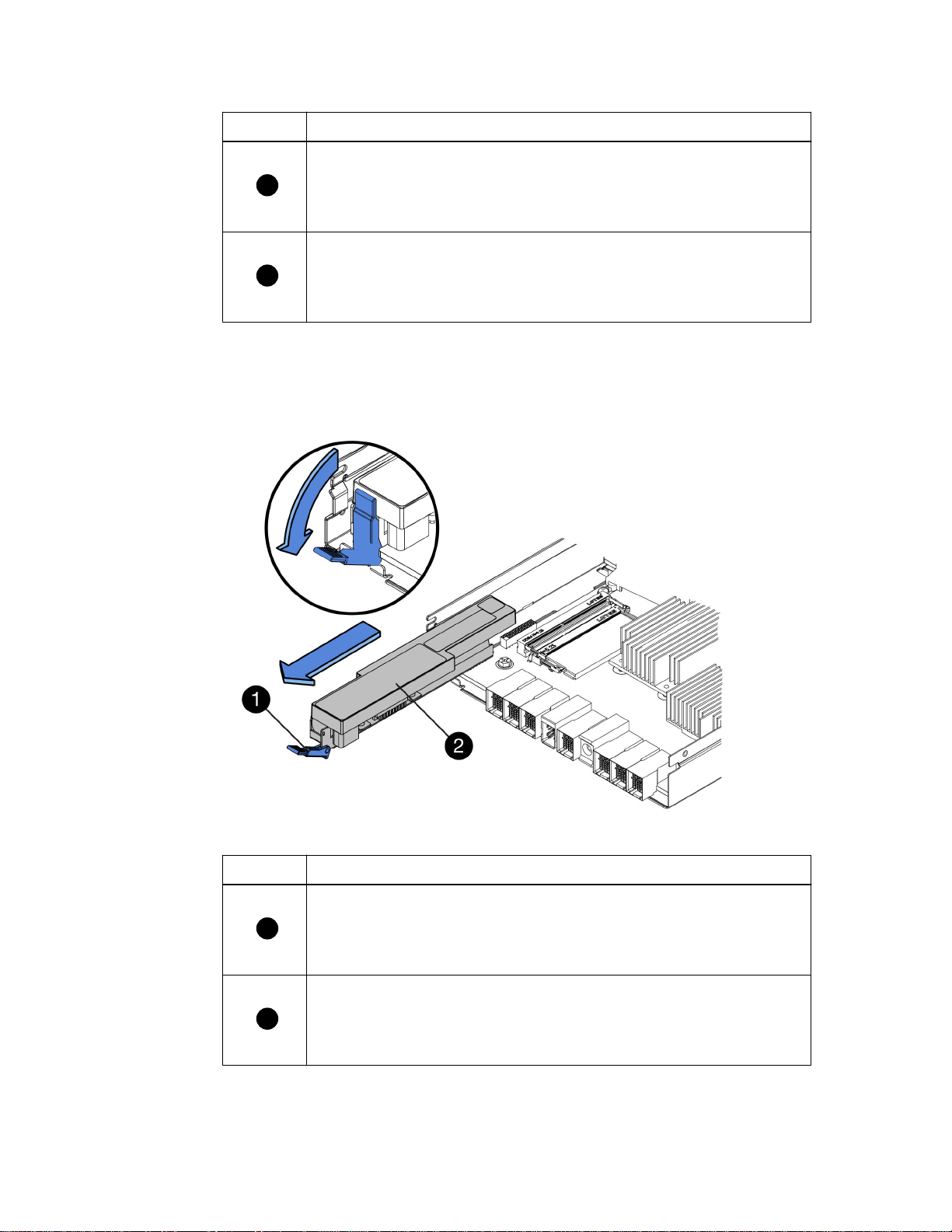
1
2
1
2
| Hardware Installation and Maintenance Guide for SG6000 Appliances
70
Item Description
b. Locate the blue release latch for the battery.
c. Unlatch the battery by pushing the release latch down and away from the controller.
Internal Cache Active LED
Battery
Item
d. Lift up on the battery, and slide it out of the controller.
e. Remove the cover from the replacement controller.
f. Orient the replacement controller so that the slot for the battery faces toward you.
Description
Battery release latch
Battery
Page 71
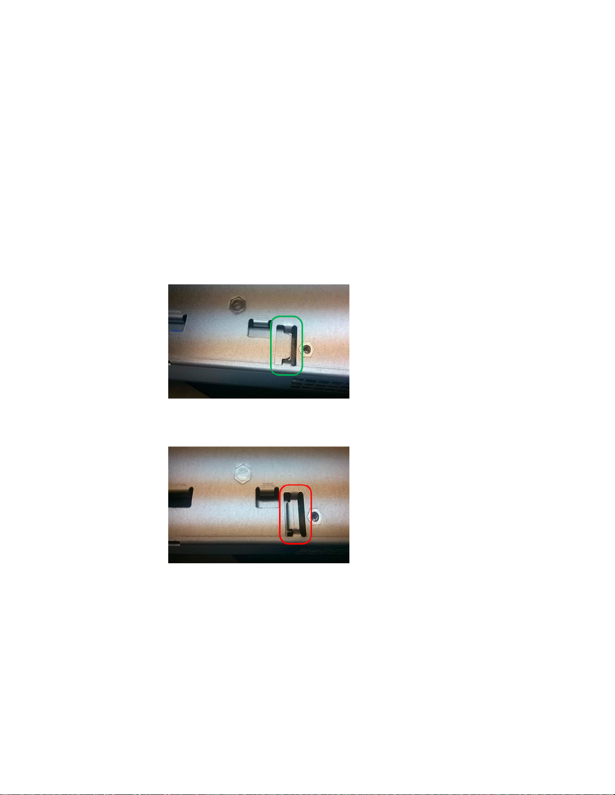
Maintaining the SG6000 appliance |
g. Insert the battery into the controller at a slight downward angle.
You must insert the metal flange at the front of the battery into the slot on the bottom of the
controller, and slide the top of the battery beneath the small alignment pin on the left side of
the controller.
h. Move the battery latch up to secure the battery.
When the latch clicks into place, the bottom of the latch hooks into a metal slot on the chassis.
i. Turn the controller over to confirm that the battery is installed correctly.
Attention: Possible hardware damage – The metal flange at the front of the battery must
be completely inserted into the slot on the controller (as shown in the first figure). If the
battery is not installed correctly (as shown in the second figure), the metal flange might
contact the controller board, causing damage.
•
Correct – The battery's metal flange is completely inserted in the slot on the
controller:
71
• Incorrect – The battery's metal flange is not inserted into the slot on the controller:
j. Replace the controller cover.
6. Install the replacement controller into the appliance.
a. Turn the controller over, so that the removable cover faces down.
b. With the cam handle in the open position, slide the controller all the way into the appliance.
c. Move the cam handle to the left to lock the controller in place.
d. Replace the cables and SFPs.
e. If the original controller used DHCP for the IP address, locate the MAC address on the label
on the back of the replacement controller. Ask your network administrator to associate the
Page 72
| Hardware Installation and Maintenance Guide for SG6000 Appliances
72
DNS/network and IP address for the controller you removed with the MAC address for the
replacement controller.
Note: If the original controller did not use DHCP for the IP address, the new controller will
adopt the IP address of the controller you removed.
7. Bring the controller online using SANtricity System Manager:
a. Select Hardware.
b. If the graphic shows the drives, select Show back of shelf.
c. Select the controller you want to place online.
d. Select Place Online from the context menu, and confirm that you want to perform the
operation.
e. Verify that the seven-segment display shows a state of 99.
Confirm that the new controller is Optimal, and collect support data.
8.
Related information
E-Series and SANtricity 11.5 Documentation Center
Replacing hardware components in the E2860 controller shelf
You might need to replace a controller battery, drive, fan, or power supply in the E2860 controller
shelf.
Before you begin
You have the E-Series hardware replacement procedure.
About this task
To replace the battery in the E2800 controller, see the instructions in this guide for replacing an
E2800 controller. Those instructions describe how to remove a controller from the appliance, remove
the battery from the controller, install the battery, and replace the controller.
To replace a drive, power supply, fan, or drive drawer in the E2860 controller shelf, access the ESeries procedures for maintaining E2800 hardware.
FRU
Drive Replacing a drive in 60-drive shelves
Power canister Replacing a power canister in 60-drive shelves
Fan canister Replacing a fan canister in 60-drive shelves
Drive drawer Replacing a drive drawer in 60-drive shelves
See E-Series instructions for
Related tasks
Replacing an E2800 controller
Related information
on page 67
E-Series and SANtricity 11.5 Documentation Center
Page 73

Maintaining the SG6000 appliance |
NetApp Documentation: Product Library A-Z
Replacing the SG6000-CN controller
You might need to replace the SG6000-CN controller if it is not functioning optimally or if it has
failed.
Before you begin
• You have a replacement controller with the same part number as the controller you are replacing.
• You have labels to identify each cable that is connected to the controller.
About this task
The appliance Storage Node will not be accessible when you replace the SG6000-CN controller
controller. If the SG6000-CN controller is functioning sufficiently, you can perform a controlled
shutdown at the start of this procedure.
Note: If you are replacing the controller before installing StorageGRID Webscale software, you
might not be able to access the StorageGRID Appliance Installer immediately after completing this
procedure. While you can access the StorageGRID Appliance Installer from other hosts on the
same subnet as the appliance, you cannot access it from hosts on other subnets. This condition
should resolve itself within 15 minutes (when any ARP cache entries for the original controller
time out), or you can clear the condition immediately by purging any old ARP cache entries
manually from the local router or gateway.
73
Steps
1. If the SG6000-CN controller is functioning sufficiently to allow for a controlled shutdown, shut
down the SG6000-CN controller.
a. From the service laptop, log in to the grid node:
i. Enter the following command: ssh admin@grid_node_IP
ii. Enter the password listed in the Passwords.txt file.
iii. Enter the following command to switch to root: su -
iv. Enter the password listed in the Passwords.txt file.
When you are logged in as root, the prompt changes from $ to #.
b. Stop all StorageGRID Webscale services:
service servermanager stop
c. Shut down the SG6000-CN controller:
shutdown -h now
d. Wait for any data in cache memory to be written to the drives.
The green Cache Active LED on the back of the E2800 controller is on when cached data
needs to be written to the drives. You must wait for this LED to turn off.
2. Turn off the power switch on the front of the SG6000-CN controller.
3. If the StorageGRID Webscale networks attached to the controller use DHCP servers, update
DNS/network and IP address settings.
Page 74

| Hardware Installation and Maintenance Guide for SG6000 Appliances
74
a. Locate the MAC address label on the front of the SG6000-CN controller, and determine the
MAC address for the Admin Network port.
Note: The MAC address label lists the MAC address for the BMC management port.
To determine the MAC address for the Admin Network port, you must add 2 to the
hexadecimal number on the label. For example, if the MAC address on the label ends in 09,
the MAC address for the Admin Port would end in 0B. If the MAC address on the label
ends in (y)FF, the MAC address for the Admin Port would end in (y+1)01. You can easily
make this calculation by opening Calculator in Windows, setting it to Programmer mode,
selecting Hex, typing the MAC address, then typing + 2 =.
b. Ask your network administrator to associate the DNS/network and IP address for the
controller you removed with the MAC address for the replacement controller.
Attention: You must ensure that all IP addresses for the original controller have been
updated before you apply power to the replacement controller. Otherwise, the controller
will obtain new DHCP IP addresses when it boots up and might not be able to reconnect to
StorageGRID Webscale. This step applies to all StorageGRID Webscale networks that are
attached to the controller.
Note: If the original controller used static IP address, the new controller will automatically
adopt the IP addresses of the controller you removed.
4. Remove and replace the SG6000-CN controller:
a. Label the cables and then disconnect the cables and any SFP+ or SFP28 transceivers.
Attention: To prevent degraded performance, do not twist, fold, pinch, or step on the
cables.
b. Remove the failed controller from the cabinet or rack.
c. Install the replacement controller into the cabinet or rack.
d. Replace the cables and any SFP+ or SFP28 transceivers.
e. Power on the controller and monitor the controller LEDs and boot-up codes.
5. Confirm that the appliance Storage Node appears in the Grid Manager and that no alarms appear.
Related tasks
Installing the SG6000-CN controller in a cabinet or rack
Viewing boot-up codes for the SG6000-CN controller
Related references
Viewing status indicators and buttons on the SG6000-CN controller
on page 28
on page 59
on page 33
Replacing a power supply in the SG6000-CN controller
The SG6000-CN controller has two power supplies for redundancy. If one of the power supplies fails,
you must replace it as soon as possible to ensure that the compute controller has redundant power.
Before you begin
• You have unpacked the replacement power supply unit.
• You can confirmed that the other power supply is installed and running.
Page 75

Maintaining the SG6000 appliance |
About this task
The figure shows the two power supply units for the SG6000-CN controller, which are accessible
from the back of the controller.
Steps
Unplug the power cord from the power supply.
1.
Lift the cam handle.
2.
75
3. Press the blue latch and pull the power supply out.
4. Slide the replacement power supply into the chassis.
Ensure that the blue latch is on the right side when you slide the unit in.
Page 76
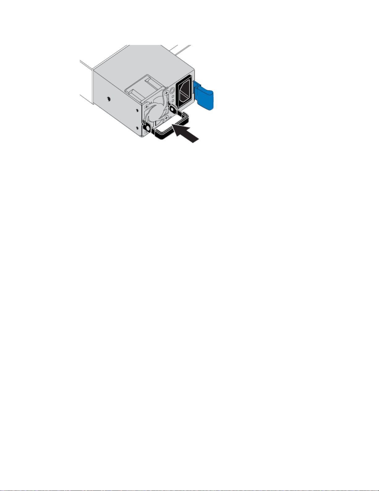
| Hardware Installation and Maintenance Guide for SG6000 Appliances
76
Push the cam handle down to secure the power supply.
5.
Attach the power cord to the power supply, and ensure that the green LED comes on.
6.
Changing the link configuration of the SG6000-CN controller
You can change the Ethernet link configuration of the SG6000-CN controller. You can change the
port bond mode, the network bond mode, and the link speed.
About this task
Options for changing the Ethernet link configuration of the SG6000-CN controller include:
• Changing Port bond mode from Fixed to Aggregate, or from Aggregate to Fixed
• Changing Network bond mode from Active-Backup to LACP, or from LACP to Active-Backup
• Enabling or disabling VLAN tagging, or changing the value of a VLAN tag
• Changing the link speed from 10-GbE to 25-GbE, or from 25-GbE to 10-GbE
Before changing the link configuration, you must place the SG6000-CN controller into maintenance
mode. Putting a StorageGRID Webscale appliance into maintenance mode might make the appliance
unavailable for remote access.
Steps
1. Follow these steps to place the SG6000-CN controller into maintenance mode:
a. From the service laptop, log in to the grid node:
i. Enter the following command: ssh admin@grid_node_IP
ii. Enter the password listed in the Passwords.txt file.
iii. Enter the following command to switch to root: su -
iv. Enter the password listed in the Passwords.txt file.
When you are logged in as root, the prompt changes from $ to #.
b. Stop all StorageGRID Webscale services:
service servermanager stop
c. Place the SG6000-CN controller into maintenance mode:
Page 77
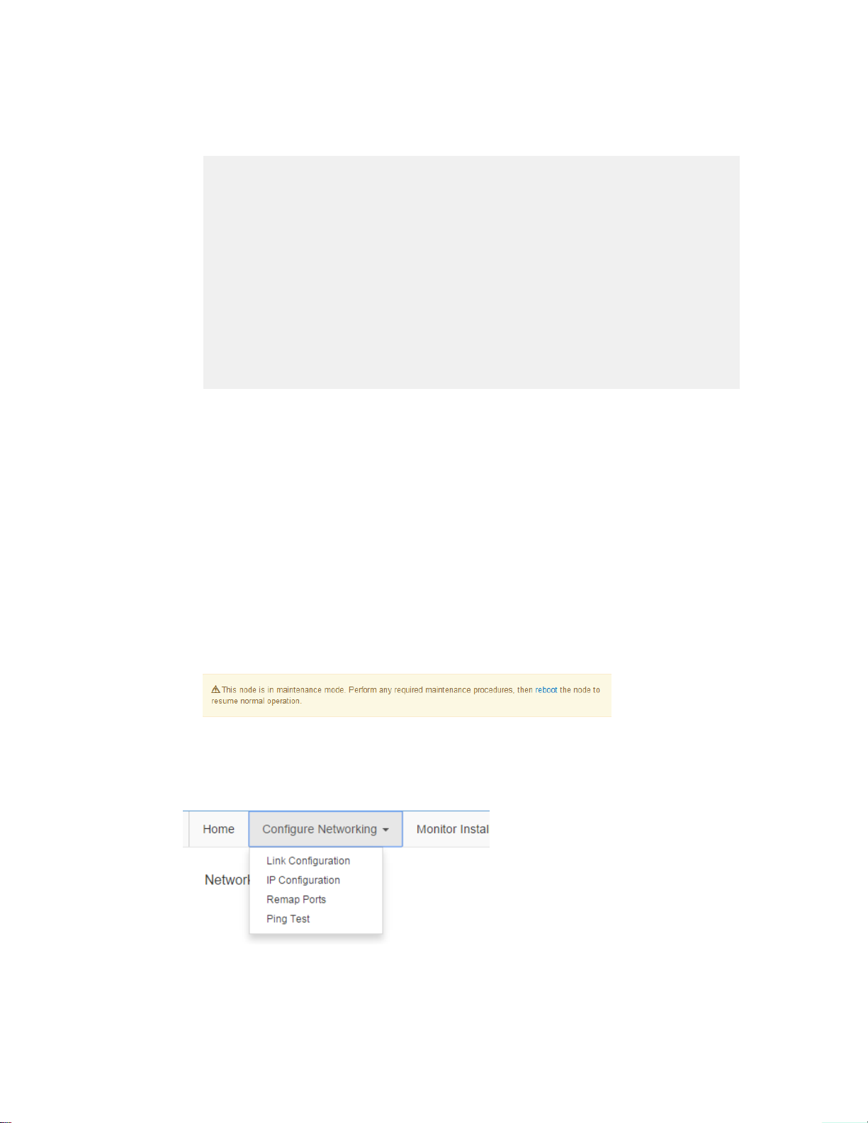
Maintaining the SG6000 appliance |
sgamaintenance
The following messages are displayed on the service laptop:
WARNING: All StorageGRID Webscale services on this node will be
shut down.
WARNING: You will have to manually exit maintenance mode before
this node will resume normal operation.
After running this command and waiting a few minutes for the node
to reboot, browse to one of the following URLs to perform any
maintenance actions, then exit maintenance mode:
http://192.168.4.138:8080
http://10.224.4.138:8080
http://47.47.4.138:8080
http://169.254.0.1:8080
Are you sure you want to continue (y/n)?
d. Enter y to continue.
The appliance reboots, which takes two or three minutes to complete.
e. Browse to any of the URLs displayed in the output of the sgamaintenance command to
access the StorageGRID Appliance Installer.
77
Note: If possible, use the URL containing the IP address of this StorageGRID Webscale
appliance's Admin Network port. Connectivity through the grid or Client Network IP
addresses might be interrupted by steps you complete later in this procedure.
Note: Accessing http://169.254.0.1:8080 requires a direct connection to the
rightmost RJ-45 port on the SG6000-CN controller.
f. Confirm that the appliance is in maintenance mode by noting the maintenance mode message
on the StorageGRID Appliance Installer home page.
2. From the StorageGRID Appliance Installer, select Configure Networking > Link
Configuration.
3. Make the desired changes to the link configuration.
For more information on the options, see “Configuring network links.”
4. When you are satisfied with your selections, click Save.
Page 78
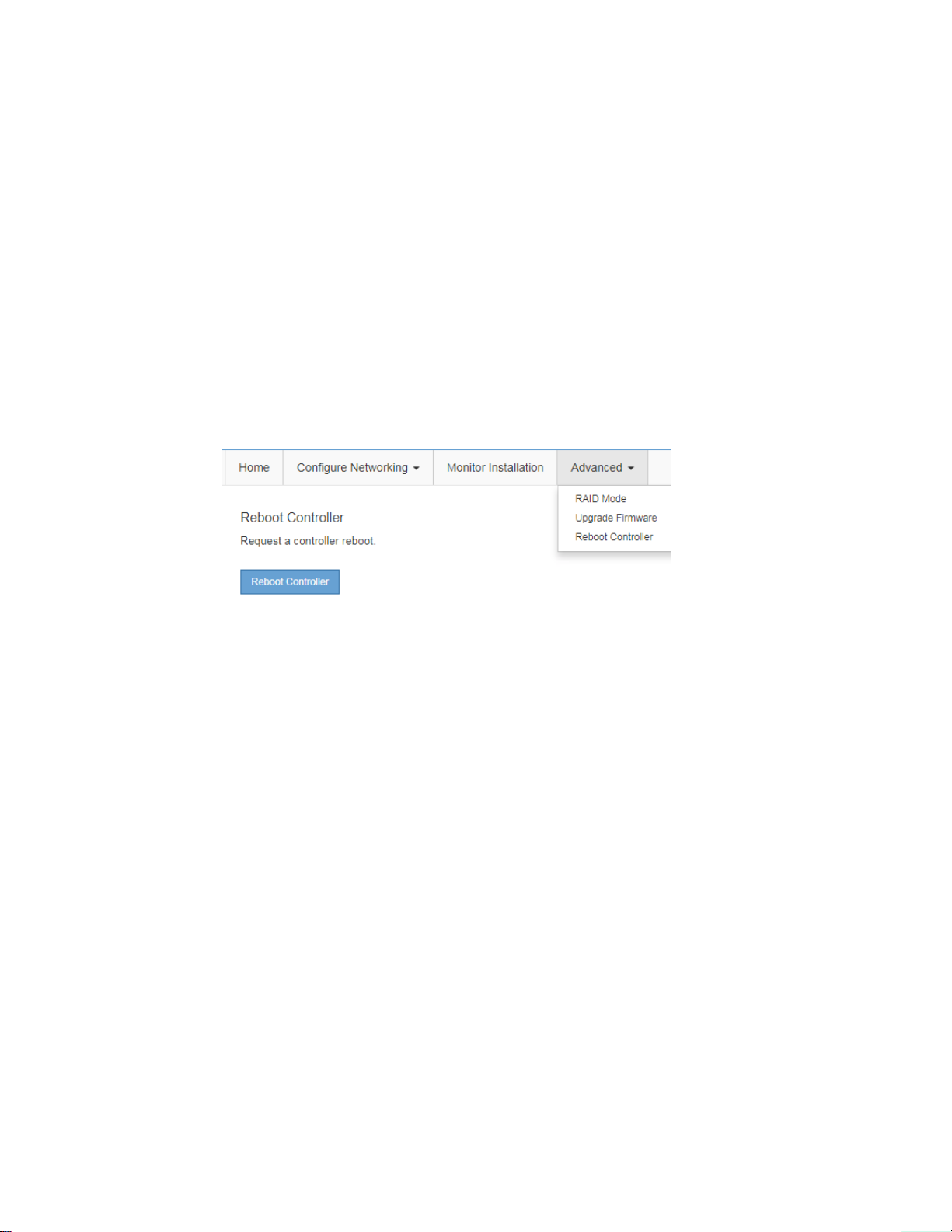
78 | Hardware Installation and Maintenance Guide for SG6000 Appliances
Note: You might lose your connection if you made changes to the network or link you are
connected through. If you are not reconnected within 1 minute, re-enter the URL for the
StorageGRID Appliance Installer using one of the other IP addresses assigned to the appliance:
http://SG6000-CN_Controller_IP:8080
5. Select Configure Networking > Ping Test from the menu.
6. Use the Ping Test tool to check connectivity to IP addresses on any networks that might have been
affected by the link configuration changes you made in step 3.
In addition to any other tests you choose to perform, confirm that you can ping the Grid Network
IP address of the primary Admin Node, and the Grid Network IP address of at least one other
Storage Node. If necessary, return to step
Once you are satisfied that your link configuration changes are working, return the appliance to
7.
3
, and correct any link configuration issues.
normal operating mode:
a. From the StorageGRID Appliance Installer, select Advanced > Reboot Controller.
b. Click Reboot Controller.
The appliance reboots and rejoins the grid. This process can take up to 20 minutes.
c. Monitor the status of the upgraded appliance Storage Node in the Grid Manager.
Verify that the appliance returns to the expected status.
Related tasks
Configuring network links
on page 44
Page 79

Copyright information
Copyright © 2018 NetApp, Inc. All rights reserved. Printed in the U.S.
No part of this document covered by copyright may be reproduced in any form or by any means—
graphic, electronic, or mechanical, including photocopying, recording, taping, or storage in an
electronic retrieval system—without prior written permission of the copyright owner.
Software derived from copyrighted NetApp material is subject to the following license and
disclaimer:
THIS SOFTWARE IS PROVIDED BY NETAPP "AS IS" AND WITHOUT ANY EXPRESS OR
IMPLIED WARRANTIES, INCLUDING, BUT NOT LIMITED TO, THE IMPLIED
WARRANTIES OF MERCHANTABILITY AND FITNESS FOR A PARTICULAR PURPOSE,
WHICH ARE HEREBY DISCLAIMED. IN NO EVENT SHALL NETAPP BE LIABLE FOR ANY
DIRECT, INDIRECT, INCIDENTAL, SPECIAL, EXEMPLARY, OR CONSEQUENTIAL
DAMAGES (INCLUDING, BUT NOT LIMITED TO, PROCUREMENT OF SUBSTITUTE
GOODS OR SERVICES; LOSS OF USE, DATA, OR PROFITS; OR BUSINESS INTERRUPTION)
HOWEVER CAUSED AND ON ANY THEORY OF LIABILITY, WHETHER IN CONTRACT,
STRICT LIABILITY, OR TORT (INCLUDING NEGLIGENCE OR OTHERWISE) ARISING IN
ANY WAY OUT OF THE USE OF THIS SOFTWARE, EVEN IF ADVISED OF THE
POSSIBILITY OF SUCH DAMAGE.
79
NetApp reserves the right to change any products described herein at any time, and without notice.
NetApp assumes no responsibility or liability arising from the use of products described herein,
except as expressly agreed to in writing by NetApp. The use or purchase of this product does not
convey a license under any patent rights, trademark rights, or any other intellectual property rights of
NetApp.
The product described in this manual may be protected by one or more U.S. patents, foreign patents,
or pending applications.
Data contained herein pertains to a commercial item (as defined in FAR 2.101) and is proprietary to
NetApp, Inc. The U.S. Government has a non-exclusive, non-transferrable, non-sublicensable,
worldwide, limited irrevocable license to use the Data only in connection with and in support of the
U.S. Government contract under which the Data was delivered. Except as provided herein, the Data
may not be used, disclosed, reproduced, modified, performed, or displayed without the prior written
approval of NetApp, Inc. United States Government license rights for the Department of Defense are
limited to those rights identified in DFARS clause 252.227-7015(b).
Page 80

80
Trademark
NETAPP, the NETAPP logo, and the marks listed on the NetApp Trademarks page are trademarks of
NetApp, Inc. Other company and product names may be trademarks of their respective owners.
http://www.netapp.com/us/legal/netapptmlist.aspx
Page 81

How to send comments about documentation and receive update notifications
You can help us to improve the quality of our documentation by sending us your feedback. You can
receive automatic notification when production-level (GA/FCS) documentation is initially released or
important changes are made to existing production-level documents.
If you have suggestions for improving this document, send us your comments by email.
To help us direct your comments to the correct division, include in the subject line the product name,
version, and operating system.
If you want to be notified automatically when production-level documentation is released or
important changes are made to existing production-level documents, follow Twitter account
@NetAppDoc.
You can also contact us in the following ways:
• NetApp, Inc., 1395 Crossman Ave., Sunnyvale, CA 94089 U.S.
81
• Telephone: +1 (408) 822-6000
• Fax: +1 (408) 822-4501
• Support telephone: +1 (888) 463-8277
Page 82

82 | Hardware Installation and Maintenance Guide for SG6000 Appliances
Index
10/25-GbE ports
bond modes
changing link configuration
setting link speed
16
76
44
A
active-backup bond mode
described
setting
Admin Network
configuring IP address for appliance
described
aggregate port bond mode
described
setting
alerts
setting up for the appliance
appliance
AutoSupport
boot-up status codes
changing password
configuring hardware
configuring links
configuring SANtricity System Manager
configuring StorageGRID connections
deploying as a Storage Node
Drive Security
installation overview
installing hardware
installing into cabinet or rack 25,
maintaining
powering on
preparing the site
setting up alerts
verifying connectivity
AutoSupport
setting up for the appliance
17
44
16
17
44
40
40
32
40
35
44
40
10
24
65
31
12
40
51
40
58
28
48
42
35
C
cabinet
installing appliance 25,
requirements
cables
connecting to appliance
included in product shipment
required for installation
Client Network
configuring IP address for appliance
described
comments
how to send feedback about documentation
controllers
overview
replacing E2800
replacing SG6000-CN
SG6000 appliance
verifying connectivity
12
16
7
28
29
13
14
48
67
73
5
51
D
DDS
setting for volume configuration
dimensions
SG6060
documentation
how to receive automatic notification of changes to
12
81
how to send feedback about
drive drawer
replacing
Drive Security
using
drives
installing in E2860 controller shelf
replacing
72
40
72
56
81
27
81
B
battery
replacing
BMC
accessing
boot-up codes
changing password
configuring
error codes
SNMP settings
BMC port
IP address
boot-up codes
SG6000-CN controller
browsers
supported
67
54
52
15
52
60
59
55
54
59
E
E2800 controller
accessing SANtricity System Manager
connectors
described
network connections
overview
replacing
setting static IP address
upgrading SANtricity OS Software
E2800 seven-segment display
during power on
E2860 controller shelf
installing drives
replacing components
reviewing hardware status in SANtricity System
Manager
email alerts
7
5
16
7
67
37
65
32
27
72
41
35
Page 83

Index | 83
setting up for the appliance
errors
E2800 seven-segment display
SG6000-CN controller 33,
40
32
60
F
fan
replacing in E2860 controller shelf
feedback
how to send comments about documentation
firmware
upgrading for E2800 controller
fixed port bond mode
described
setting
17
44
65
G
Grid Network
configuring IP address for appliance
described
16
H
hardware
controller overview
items included in product shipment
troubleshooting setup
verifying connectivity
hardware configuration
accessing SANtricity System Manager
overview
reviewing in SANtricity System Manager
hardware installation
boot-up status codes
cabling the appliance
connecting power cords and applying power
overview
racking the appliance 25,
registering the appliance
required hardware and tools
HE errod code
troubleshooting
35
24
7
62
51
32
29
28
24
14
59
I
indicators
SG6000-CN controller
information
how to send feedback about improving
documentation
installation
gathering data for
phases
10
planning
troubleshooting
troubleshooting connection issues
IP address
SG6000-CN controller
IP configuration
StorageGRID networks
12
33
81
18
59
43
48
62
72
13
48
35
41
31
81
L
LACP bond mode
described
setting
LEDs
SG6000-CN controller
Link Aggregation Control Protocol mode
described
link speed
changing
links
appliance Storage Node
17
44
33
17
76
44
M
maintenance
replacing components
replacing power supply in SG6000-CN controller
SG6000 appliance
management ports
setting IP address for E2800 controller
72
65
N
network bond mode
changing
network links
appliance Storage Node
76
44
P
password
changing for BMC interface
changing for SANtricity System Manager
port bond mode
changing
power supply
replacing in E2860 controller shelf
replacing in SG6000-CN controller
76
54
72
74
R
rack
installing appliance 25,
requirements
RAID6
setting for volume configuration
rebooting
SG6000-CN controller
registering
appliance hardware
remapping ports
appliance Storage Node
replacing
E2800 controller
SG6000-CN controller
12
28
56
63
24
57
67
73
S
SANtricity OS Software
74
37
40
Page 84

84 | Hardware Installation and Maintenance Guide for SG6000 Appliances
upgrading on E2800 controllers
SANtricity System Manager
accessing
configuring
initial set up
reviewing hardware status
SG6000 appliance
features
SG6000-CN controller
10/25-GbE ports
accessing BMC interface 52,
boot-up codes
changing link configuration
configuring BMC interface
connectors
described
display and status LEDs
error codes
network connections
overview
replacing
replacing power supply
setting IP addresses for StorageGRID
SNMP settings
SG6060
configuring RAID6 mode
described
specifications
shipment
content of boxes
site
preparing
size
SG6060
SNMP
E2860 controller shelf
SG6000-CN controller
SSD drives
location of in E2860 controller shelf
Storage Node
deploying StorageGRID appliance
StorageGRID Appliance Installer
35
35
40
5
16
59
7
5
33
60
16
7
73
74
55
5
12
13
12
12
40
55
41
56
76
52
54
65
58
27
48
accessing
suggestions
how to send feedback about documentation
43
T
tools
required for installation
troubleshooting
connection issues
E2800 seven-segment display
error codes for SG6000-CN controller
hardware setup
hardware setup hangs
indicators on SG6000-CN controller
installation
LEDs on SG6000-CN controller
unable to connect to the appliance
Twitter
how to receive automatic notification of
documentation changes
62
59
14
62
32
62
81
V
VLAN tags
aggregate port bond mode
changing
using
76
44
17
W
web browsers
supported
workflow
configuring hardware
installation planning
installing hardware
overview
15
35
12
24
10
81
60
33
33
62
 Loading...