

Page 1

NetApp® E-Series Storage Systems
Model 3040 40U Cabinet Guide
NetApp, Inc.
495 East Java Drive
Sunnyvale, CA 94089 U.S.A.
Telephone: +1 (408) 822-6000
Fax: +1 (408) 822-4501
Support telephone: +1 (888) 4-NETAPP
Feedback: [email protected]
Web: http://www.netapp.com
Part number: 215-07664_B0
May 2013
Page 2

Copyright information
Copyright © 1994–2013 NetApp, Inc. All rights reserved. Printed in the U.S.A.
No part of this document covered by copyright may be reproduced in any form or by any means—
graphic, electronic, or mechanical, including photocopying, recording, taping, or storage in an
electronic retrieval system—without prior written permission of the copyright owner.
Software derived from copyrighted NetApp material is subject to the following license and disclaimer:
THIS SOFTWARE IS PROVIDED BY NETAPP "AS IS" AND WITHOUT ANY EXPRESS OR
IMPLIED WARRANTIES, INCLUDING, BUT NOT LIMITED TO, THE IMPLIED WARRANTIES
OF MERCHANTABILITY AND FITNESS FOR A PARTICULAR PURPOSE, WHICH ARE
HEREBY DISCLAIMED. IN NO EVENT SHALL NETAPP BE LIABLE FOR ANY DIRECT,
INDIRECT, INCIDENTAL, SPECIAL, EXEMPLARY, OR CONSEQUENTIAL DAMAGES
(INCLUDING, BUT NOT LIMITED TO, PROCUREMENT OF SUBSTITUTE GOODS OR
SERVICES; LOSS OF USE, DATA, OR PROFITS; OR BUSINESS INTERRUPTION) HOWEVER
CAUSED AND ON ANY THEORY OF LIABILITY, WHETHER IN CONTRACT, STRICT
LIABILITY, OR TORT (INCLUDING NEGLIGENCE OR OTHERWISE) ARISING IN ANY WAY
OUT OF THE USE OF THIS SOFTWARE, EVEN IF ADVISED OF THE POSSIBILITY OF SUCH
DAMAGE.
NetApp reserves the right to change any products described herein at any time, and without notice.
NetApp assumes no responsibility or liability arising from the use of products described herein, except
as expressly agreed to in writing by NetApp. The use or purchase of this product does not convey a
license under any patent rights, trademark rights, or any other intellectual property rights of NetAp p.
The product described in this manual may be protected by one or more U.S. patents, foreign patents, or
pending applications.
RESTRICTED RIGHTS LEGEND: Use, duplication, or disclosure by the government is subject to
restrictions as set forth in subparagraph (c)(1)(ii) of the Rights in Technical Data and Computer
Software clause at DFARS 252.277-7103 (October 1988) and FAR 52-227-19 (June 1987).
ii Copyright information
Page 3

Trademark information
NetApp, the NetApp logo, Network Appliance, the Network Appliance logo, Akorri, ApplianceWatch,
ASUP, AutoSupport, BalancePoint, BalancePoint Predictor, Bycast, Campaign Express,
ComplianceClock, Cryptainer, CryptoShred, Data ONTAP, DataFabric, DataFort, Decru, Decru
DataFort, DenseStak, Engenio, Engenio logo, E-Stack, FAServer, FastStak, FilerView, FlexCache,
FlexClone, FlexPod, FlexScale, FlexShare, FlexSuite, FlexVol, FPolicy, GetSuccessful, gFiler, Go
further, faster, Imagine Virtually Anything, Lifetime Key Management, LockVault, Manage ONTAP,
MetroCluster, MultiStore, NearStore, NetCache, NOW (NetApp on the Web), Onaro, OnCommand,
ONTAPI, OpenKey, PerformanceStak, RAID-DP, ReplicatorX, SANscreen, SANshare, SANtricity,
SecureAdmin, SecureShare, Select, Service Builder, Shadow Tape, Simplicity, Simulate ONTAP,
SnapCopy , SnapDirector, SnapDrive, SnapFilter, SnapLock, SnapManager, SnapMigrator,
SnapMirror, SnapMover, SnapProtect, SnapRestore, Snapshot, SnapSuite, SnapValidator, SnapVault,
StorageGRID, StoreVault, the StoreVault logo, SyncMirror, Tech OnTap, The evolution of storage,
Topio, vFiler, VFM, Virtual File Manager, VPolicy, WAFL, Web Filer, and XBB are trademarks or
registered trademarks of NetApp, Inc. in the United States, other countries, or both.
IBM, the IBM logo, and ibm.com are trademarks or registered trademarks of International Business
Machines Corporation in the United States, other countries, or both. A complete and current list of
other IBM trademarks is available on the Web at
Apple is a registered trademark and QuickTime is a trademark of Apple, Inc. in the U.S.A. and/or other
countries. Microsoft is a registered trademark and Windows Media is a trademark of Microsoft
Corporation in the U.S.A. and/or other countries. RealAudio, RealNetworks, RealPlayer, RealSystem,
RealText, and RealVideo are registered trademarks and RealMedia, RealProxy, and SureStream are
trademarks of RealNetworks, Inc. in the U.S.A. and/or other countries.
www.ibm.com/legal/copytrade.shtml.
All other brands or products are trademarks or registered trademarks of their respective holders and
should be treated as such.
NetApp, Inc. is a licensee of the CompactFlash and CF Logo trademarks.
NetApp, Inc. NetCache is certified RealSystem compatible.
Trademark information iii
Page 4

How to send your comments
You can help us to improve the quality of our documentation by sending us your feedback.
Your feedback is important in helping us to provide the most accurate and high-quality information. If
you have suggestions for improving this document, send us your comments by email to
[email protected]. To help us direct your comments to the correct division, include in the
subject line the product name, version, and operating system.
You can also contact us in the following ways:
• NetApp, Inc., 495 East Java Drive, Sunnyvale, CA 94089 U.S
• Telephone: +1 (408) 822-6000
• Fax: +1 (408) 822-4501
• Support telephone: +1 (888) 463-8277
iv How to send your comments
Page 5

Ta ble of Contents
Chapter 1 Specifications of the Model 3040 40U Cabinet . . . . . . . . . . . . . . . . . . . . . . . . . . . . 1
Power Requirements and Heat Dissipation . . . . . . . . . . . . . . . . . . . . . . . . . . . . . 3
Cabinet Limitations . . . . . . . . . . . . . . . . . . . . . . . . . . . . . . . . . . . . . . . . . . . . . . . 4
Chapter 2 Installing the Cabinet . . . . . . . . . . . . . . . . . . . . . . . . . . . . . . . . . . . . . . . . . . . . . . . . 9
Gathering the Required Tools and Equipment. . . . . . . . . . . . . . . . . . . . . . . . . . . 9
Preparing to Move the Cabinet. . . . . . . . . . . . . . . . . . . . . . . . . . . . . . . . . . . . . . 10
Estimating the Cabinet Weight . . . . . . . . . . . . . . . . . . . . . . . . . . . . . . . . . . 10
Acclimating the Cabinet . . . . . . . . . . . . . . . . . . . . . . . . . . . . . . . . . . . . . . . 11
Removing the Packing Material . . . . . . . . . . . . . . . . . . . . . . . . . . . . . . . . . 12
Checking the Shipping Contents. . . . . . . . . . . . . . . . . . . . . . . . . . . . . . . . . 12
Removing the Components. . . . . . . . . . . . . . . . . . . . . . . . . . . . . . . . . . . . . 12
Moving the Cabinet . . . . . . . . . . . . . . . . . . . . . . . . . . . . . . . . . . . . . . . . . . . . . . 12
Chapter 3 Completing the Installation . . . . . . . . . . . . . . . . . . . . . . . . . . . . . . . . . . . . . . . . . . 15
Lowering the Stability Foot . . . . . . . . . . . . . . . . . . . . . . . . . . . . . . . . . . . . . . . . 15
Reinstalling the Trays. . . . . . . . . . . . . . . . . . . . . . . . . . . . . . . . . . . . . . . . . . . . . 16
Installing the Cable Spools and the Tie Wraps . . . . . . . . . . . . . . . . . . . . . . . . . 16
Installing Other Components . . . . . . . . . . . . . . . . . . . . . . . . . . . . . . . . . . . . . . . 18
Chapter 4 Installing Additional Mounting Rails . . . . . . . . . . . . . . . . . . . . . . . . . . . . . . . . . . 19
Chapter 5 Turning on the Power with 72A PDUs . . . . . . . . . . . . . . . . . . . . . . . . . . . . . . . . . 21
Regulatory Compliance Statements. . . . . . . . . . . . . . . . . . . . . . . . . . . . . . . . . . . . . . . . . . . . . . . . . . . . . . . . . FCC-1
Table of Contents v
Page 6

vi Table of Contents
Page 7
Specifications of the Model 3040 40U Cabinet
The Model 3040 40U cabinet has these standard features:
A detachable rear door
Standard Electronic Industry Association (EIA) support rails that provide
mounting holes for installing devices into a standard 48.3-cm (19-in.) wide
cabinet
Four roller casters and four adjustable leveling feet that are located beneath the
cabinet for moving the cabinet and then lev eling the cabinet in its final location
A stability foot that stabilizes the cabinet after it is installed in its permanent
location
Access openings for interface cables
Two AC power distribution units (PDUs) – each of which has a separate set of
power cords for each side – that allow integrated power connection and power
handling capacity for controller-drive trays and drive trays
WARNING (W05) Risk of bodily injury – If the bottom half of the cabinet is empty ,
do not install components in the top half of the cabinet. If the top half of the cabinet is
too heavy for the bottom half, the cabinet might fall and cause bodily injury. Always
install a component in the lowest available position in the cabinet.
WARNING (W07) Risk of bodily injury – Only move a populated cabinet with a
forklift or adequate help from other persons. Always push the cabinet from the front to
prevent it from falling over. A fully populated cabinet can weigh more than 909 kg
(2000 lb). The cabinet is difficult to move, e ven on a flat surface. If you must mo ve the
cabinet along an inclined surface, remove the components from the top half of the
cabinet, and make sure that you have adequate help.
1
Chapter 1: Specifications of the Model 3040 40U Cabinet 1
Page 8
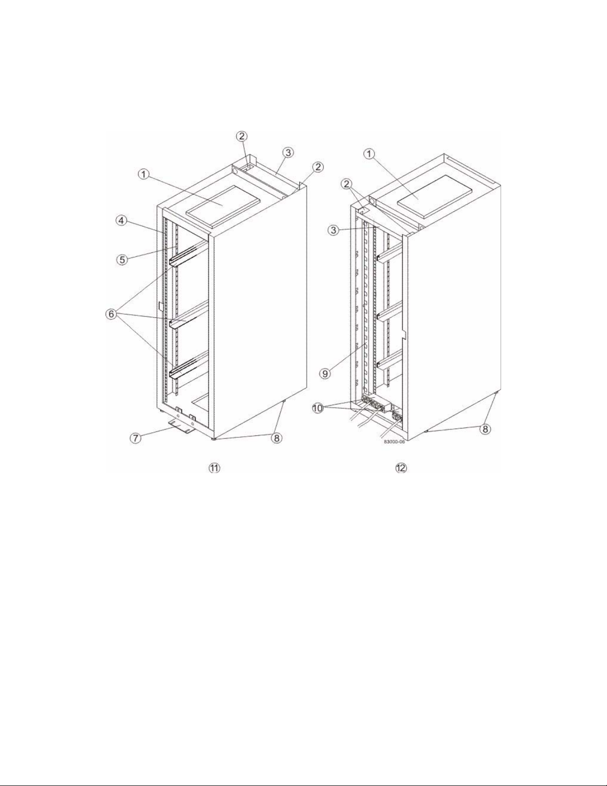
Figure 1 Components of the Model 3040 40U Cabinet – Front View
and Rear View
1. Ventilation Cover
2. Interface Cable Access Openings
3. Rear Plate
4. EIA Support Rails
5. Vertical Support Rails
6. Cabinet Mounting Rails
7. Stability Foot
8. Adjustable Leveling Feet
9. Power Strip
10. AC Power Distribution Units
11. Front of the Cabinet
12. Rear of the Cabinet
2 Model 3040 40U Cabinet Installation
Page 9
You can configure the cabinet to meet your data storage needs. Standard cabinet
configurations consist of a combination of these types of trays:
Controller-drive tray – Contains drives, redundant cooling fans and power
supplies, and, depending on the model, one or two controllers.
Drive tray – Contains drives, redundant cooling fans and power supplies, and
one or two environmental services modules (ESMs).
Power Requirements and Heat Dissipation
The cabinet is rated at 200 VAC through 240 VAC at 50 Hz to 60 Hz, and it operates
to ±10 percent of that range. The cabinet contains a power strip that provides 72A of
usable power through six 12A banks of power. This power is provided by 24 ICE320
power outlets on each PDU.
For the 72A power strips, power cord C1 supplies power to the bottom eight outlets,
power cord C2 supplies power to the middle eight outlets, and power cord C3 supplies
power to the top eight outlets. Each PDU is clearly labelled C1, C2, or C3 where the
power cords connect. Each power outlet is rated at 10A maximum. A 15A circuit
breaker protects each of the six 12A banks. Each circuit breaker is labeled on each
PDU.
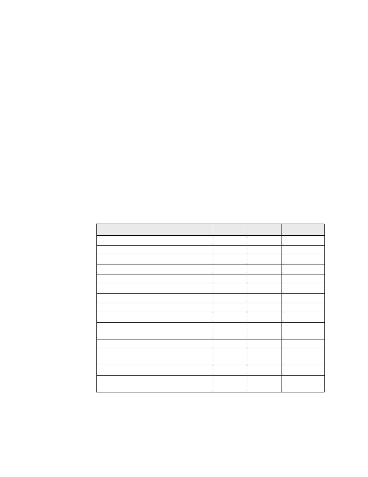
T a ble 1 Power Calculations and Heat Calculations for the Cabinet
Component kVA Watts Btu/Hr
Cabinet PDU (72A PDUs) 14.4 14400 49176
Cabinet PDU/12A bank (72A PDUs) 2.40* 2400* 8196*
E2612 controller-drive tray 0.400 399 1366
E2624 controller-drive tray 0.331 329.6 1127.1
E2660 controller-drive tray 1.268 1222 4180
E5412 controller-drive tray 0.589 589 2016
E5424 controller-drive tray 0.567 567 1935
E5460 controller-drive tray 1.246 1204 4119
E5512 controller-drive tray (200 VAC typical) .668 662 2 262
E5512 controller-drive tray
(200 VAC maximum)
E5524 controller-drive tray (200 VAC typical) .495 483 1653
E5524 controller-drive tray
(200 VAC maximum)
E5560 controller-drive tray (200 VAC typical) 1.146 1097 3751
E5560 controller-drive tray
(200 VAC maximum)
.674 670 2293
.561 554 1896
1.191 1179 4032
Chapter 1: Specifications of the Model 3040 40U Cabinet 3
Page 10

Component kVA Watts Btu/Hr
DE1600 drive tray 0.276 276 945
DE5600 drive tray 0.241 240. 821
DE6600 drive tray 1.268 1222 4180
* The maximum ratings at 200 VAC. The Btu calculation is based on the maximum current
rating that the power distribution unit can provide.
Cabinet Limitations
Tab le 2 lists the limitations when populating your cabinet with DE1600 drive trays.
NOTE A 3040 40U cabinet can hold a maximum of twenty 12-drive trays. Of these
trays, a maximum of 10 can be controller-drive trays, so the remaining 10 trays mu st
be drive trays.
Table 2 DE1600 Drive Trays That Can Be Installed in the Cabinet
Maximum Number of
Controller-Drive
Trays
1 E2612 controller-drive tray or E2624
1 E2624 controller-drive tray (duplex
2 E2612 controller-drive tray (duplex
1 E5412 controller-drive tray 15
1 E5424 controller-drive tray 15
1 E5460 controller-drive tray 15
1 E5512 controller-drive tray 15
1 E5524 controller-drive tray 15
1 E5560 controller-drive tray 15
Controller-Drive Tray
controller-drive tray
configuration)
configuration)
Maximum
Number of
DE1600 Drive
Trays
1
6
7
Tab le 3 lists the limitations when populating your cabinet with DE5600 drive trays.
NOTE A 3040 40U cabinet can hold a maximum of twenty 24-drive trays. Of these
trays, a maximum of 10 can be controller-drive trays, so the remaining 10 trays mu st
be drive trays.
4 Model 3040 40U Cabinet Installation
Page 11
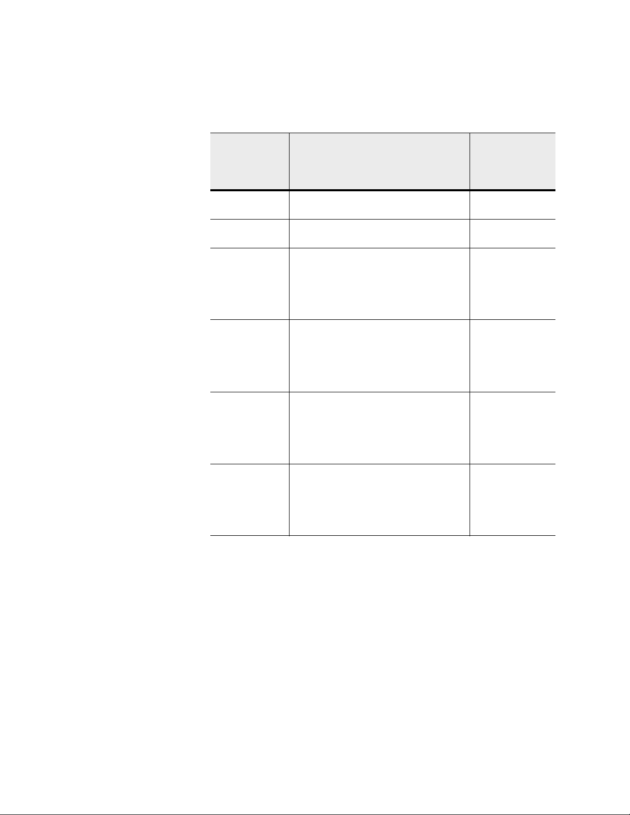
Table 3 DE5600 Drive Trays That Can Be Installed in the Cabinet
Maximum
Number of
Controller-Drive
Trays
1 E2600 controller-drive tray with 24 drives
2 E2600 controller-drive tray with 12 drives
1 E5412 controller-drive tray 7 with InfiniBand
1 E5424 controller-drive tray 9 with InfiniBand
1 E5460 controller-drive tray 7 with InfiniBand
1 E5512 controller-drive tray 7 with InfiniBand
Controller-Drive Tray
(duplex configuration)
(duplex configuration)
Maximum
Number of
DE5600 Drive
Trays
3
4
host connections
13 without
InfiniBand host
connections
host connections
15 without
InfiniBand host
connections
host connections
13 without
InfiniBand host
connections
host connections
13 without
InfiniBand host
connections
Chapter 1: Specifications of the Model 3040 40U Cabinet 5
Page 12

Maximum
Number of
Controller-Drive
Trays
Controller-Drive Tray
Maximum
Number of
DE5600 Drive
Trays
1 E5524 controller-drive tray 9 with InfiniBand
host connections
15 without
InfiniBand host
connections
1 E5560 controller-drive tray 7 with InfiniBand
host connections
13 without
InfiniBand host
connections
*You can intermix DE1600 drive trays and DE5600 driv e trays in a cabinet with an
E2600 controller-drive tray with either 12 drives or 24 drives, provided that the
total number of drives does not exceed 96.
6 Model 3040 40U Cabinet Installation
Page 13
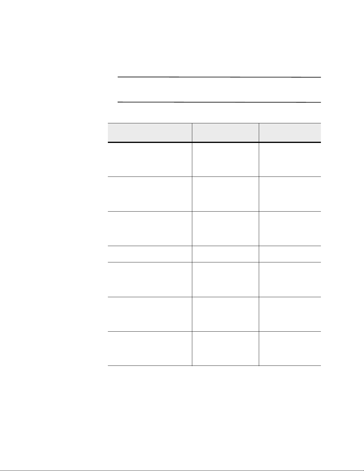
Tab le 4 lists the limitations when populating your cabinet with DE6600 drive trays.
NOTE A 3040 40U Cabinet can hold a maximum of ten 60-drive trays. Of these trays,
a maximum of five can be controller-drive trays, so the remaining five trays must be
drive trays.
Table 4 DE6600 Drive Trays That Can Be Installed in the Cabinet
Maximum Number of
Controller-Drive Trays
1 (72A PDUs are required if you
are installing DE6600 drive trays)
1 (72A PDUs are required if you
are installing DE6600 drive trays)
1 (72A PDUs are required if you
are installing DE6600 drive trays)
1 (72A PDUs are required if you
are installing DE6600 drive trays)
1 (72A PDUs are required if you
are installing DE6600 drive trays)
1 (72A PDUs are required if you
are installing DE6600 drive trays)
Controller-Drive Tray
Maximum Number of
DE6600 Drive Trays
E5412 controller-drive tray 3 with InfiniBand host
connections
6 without InfiniBand
host connections
E5424 controller-drive tray 3 with InfiniBand host
connections
6 without InfiniBand
host connections
E5460 controller-drive tray 3 with InfiniBand host
connections
5 without InfiniBand
host connections
E2660 controller-drive tray 2 without InfiniBand
host connections
E5512 controller-drive tray 3 with InfiniBand host
connections
6 without InfiniBand
host connections
E5524 controller-drive tray 3 with InfiniBand host
connections
6 without InfiniBand
host connections
1 (72A PDUs are required if you
are installing DE6600 drive trays)
E5560 controller-drive tray 3 with InfiniBand host
connections
5 without InfiniBand
host connections
Chapter 1: Specifications of the Model 3040 40U Cabinet 7
Page 14

8 Model 3040 40U Cabinet Installation
Page 15
Installing the Cabinet
Because the cabinet is a large and heavy piece of equipment, cabinet installation
requires planning with attention to detail during the installation process, wh ich
includes these steps:
1. Gather the tools and equipment required for the installation.
2. Prepare the cabinet for moving.
3. Move the cabinet to its permanent location.
4. Complete the installation.
2
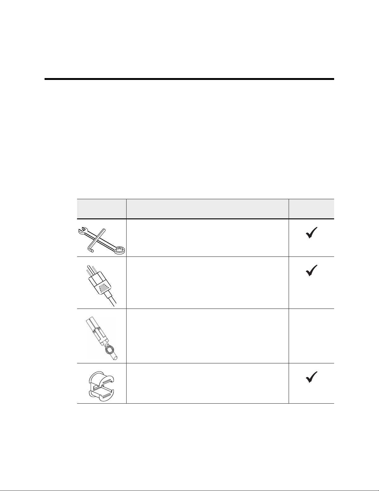
Gathering the Required Tools and Equipment
Table 5 Required for Cabinet Installation
Item
3/4-in. wrench (supplied in the shipping crate) – To raise and
lower the leveling glides under the cabinet.
1/4-in. Allen wrench – To raise and lower the stability foot in
the front of the cabinet.
AC power cords – To connect the cabinet to external power
sources (wall plugs).
SAS cables (optional) – Tw o cables are included with each dri ve
tray , while host side cables must be purchased separately.
Communication cables (optional) – To attach the tray to the
host.
Included with
the Cabinet
Refer to the initial setup guide for your controller-drive tray or
drive tray for additional required items.
Mountable cable spools – Installed along both sides of the
vertical power distribution outlets to accommodate excess cable
length and cable routing. Two cable spools are included with
each controller-drive tray. Cable spools are also shipped with
standalone drive trays
Chapter 2: Installing the Cabinet 9
Page 16

Item
Shears – To cut the metal bands on the shipping crate.
Forklift (optional) – To remove the cabinet from the shipping
pallet.
Front panel kits (optional) – To cover the empty bays at the
front of the cabinet.
Antistatic bags (optional) – To protect components that are
removed during the installation procedure for the cabinet.
Included with
the Cabinet
Preparing to Move the Cabinet
Estimating the
Cabinet Weight
Before you move the cabinet from its location in your receiving area, you must
complete these tasks:
1. Estimate the total weight of the cabinet and the trays that are to be installed in it.
2. Acclimate the cabinet.
3. Remove the packing materials.
4. Check the shipping contents.
5. Remove selected components from the cabinet.
The cabinet reliably and safely transports more than 909.1 kg (2000 lb) of capacity.
This weight value presumes that the cabinet is empty of components. You need to
know the approximate weight of the cabinet so that you can safely move it.
A TTENTION Possible equi pment damage – Cabinets with DE6600 drive trays ship
without drives to reduce shipping weight. Because a fully-populated cabinet with
DE6600 drive trays can weigh more than 909.1 kg (2000 lb), make sure that you move
the cabinet into place before you load the drives and make sure that the floor load
capability of the cabinet’s destination supports that much weight.
A TTENTION Possible damage to tray components – Do not place a DE6600 driv e
tray on a flat surface. Install the DE6600 drive tray in the cabinet before operating or
moving drawers
The total weight of the cabinet depends on the number and type of trays that are
installed in the cabinet. Table 6 lists the weights of the components that might be
installed in the cabinet and the weight of the empty cabinet. Use this table to calculate
the approximate total weight of your cabinet. Make sure that you have adequate
personnel and equipment to safely move the cabinet.
10 Model 3040 40U Cabinet Installation
Page 17
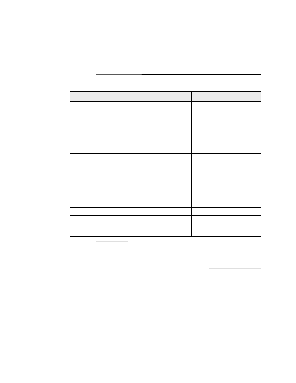
NOTE For more detailed descriptions of the controller-drive trays and drive trays
listed below, refer to the Storage System Site Preparation Guide or the initial setup
guide for each component.
Table 6 Cabinet, Tray, an d Crate Weights
Component Weight Notes
Cabinet 138.80 kg (306.0 lb) Empty with the rear door installed
Power distribution units (PDUs
19.96 kg (44.0 lb)
[pair])
Mounting rails (pair) 1.59 kg (3.50 lb)
E2612 controller-drive tray 27 kg (59.52 lb) Maximum configuration
E2624 controller-drive tray 26 kg (57.32 lb) Maximum configuration
E2660 controller-drive tray 105.2 kg (232 lb) Maximum configuration
E5412 controller-drive tray 27.92 (61.52 lb) Maximum configuration
E5424 controller-drive tray 26.92 kg (59.32 lb) Maximum configuration
E5460 controller-drive tray 105.2 kg (232 lb) Maximum configuration
E5512 controller-drive tray 27.76 kg (61.22 lb) Maximum configuration
E5524 controller-drive tray 26.76 kg (59.02 lb) Maximum configuration
E5560 controller-drive tray 105.2 kg (232 lb) Maximum configuration
DE1600 drive tray 27 kg (59.5 lb) Maximum configuration
DE5600 drive tray 26 kg (57.3 lb) Maximum configuration
DE6600 drive tray 104.1 kg (229.6 lb) Maximum configuration
Shipping crate (for worldwide
136.08 kg (300 lb) Empty
shipments only)
Acclimating the
Cabinet
ATTENTION Possible damage to tray components – If the outdoor temperature is
below 0°C (32°F) when you receive your cabinet and trays, do not immediately unpack
them or uncrate them. Exposing cold components to warm indoor temperatures can
cause condensation, which results in component damage or failures.
Make sure that the cabinet and the trays are acclimated to the indoor environment
before removing the packing materials. If the outdoor temperature is below 0°C
(32°F), leave the cabinet and trays inside of their crates indoors for at least 24 hours to
prevent condensation. Increase or decrease the 24-hour stabilization period depending
on the outside temperature upon arrival. After the cabinet and the trays have
acclimated to the indoor environment, you can unpack them.
Chapter 2: Installing the Cabinet 11
Page 18

Removing the
Packing Material
After the cabinet has acclimated to the indoor temperature, refer to the unpacking
instructions included on the front of the shipping crate, and remove the packing
material.
Checking the
Shipping Contents
Removing the
Components
Compare the packing list against the equipment that you received to make sure that all
equipment arrived at the site. If any items are missing, contact your sales
representative.
It is recommended that you remove some of the heavier components that are located
in the top of the cabinet before you move the cabinet. Removing these components
makes sure of maximum stability and keeps the center of gravity as close to the floor
as possible while the cabinet is being moved.
After the cabinet is moved to its permanent location, you will reinstall these
components in the cabinet in their original locations. It is important, therefore, to note
each component’s location prior to removing it.
Refer to the initial setup guide for each tray, as required, to identify the components
and switch locations. Refer to the Hardware Cabling Guide, as required, for common
cabling configurations.
ATTENTION Possible address conflict of loss of data access – To prevent address
conflicts and loss of data access, note the location of each tray, component, and cable
prior to its removal so that you can reinstall each item in its original location.
Complete these steps to remove the components:
1. Record the cable configuration for future reassembly if any cables must be
disconnected.
2. Remove the drive trays and controller-drive trays in the top half of the cabinet.
Keep all of the components from the same tray together.
NOTE It is not necessary to remove the po wer supplies or other components from the
rear of each tray.
3. Place each component in a separate antistatic bag. If the original shipping boxes
are available, use them to transport the components.
Moving the Cabinet
12 Model 3040 40U Cabinet Installation
Shipping crates provide built-in ramps and instructions for rolling the cabinet off the
pallet without the use of a forklift. Refer to the unpacking instructions included on the
front of the shipping crate.
When you move a cabinet, you must be aware of all of the ramps between the loading
dock and the destination. You must evaluate all ramps to make sure that the cabinet’s
center of gravity (when the cabinet is on a ramp and sitting at an angle) does not
extend beyond the cabinet’s footprint.
Page 19

It is recommended that you remove the top-most devices in your cabinet to make sure
83004-01
Rear of Cabinet
Front of Cabinet
that the cabinet is safely transported to its final location. This is especially important
if any ramp has an incline or a decline greater than 10 degrees.
NOTE Many of the cabinets are populated with drive trays. This situation results in
most of the weight in the front portion of the cabinet, making the center of gravity
closer to the front.
1. Move the cabinet to its permanent location.
Figure 2 Incorrect Method and Correct Method for Moving the
Cabinet
2. After the cabinet is in position, lower the leveling glides, which are located near
each bottom corner of the cabinet.
Chapter 2: Installing the Cabinet 13
Page 20

14 Model 3040 40U Cabinet Installation
Page 21

Completing the Installation
Four steps complete the installation procedure:
1. Lower the stability foot and the leveling glides.
2. Reinstall the trays, components, and cables.
3. Install the cable spools and tie wraps.
4. Install the other components.
3
Lowering the Stability Foot
The stability foot prevents the cabinet from falling over after it is placed in its
permanent location. Lower the stability foot and lower the leveling glides on the
cabinet when the cabinet is in its permanent location. Figure 3 provides a close-up
view of the stability foot. The leveling glides are located near each bottom corner of
the cabinet.
Figure 3 Stability Foot
Chapter 3: Completing the Installation 15
Page 22
Reinstalling the Trays
Complete these steps to reinstall the items that were removed prior to moving the
cabinet.
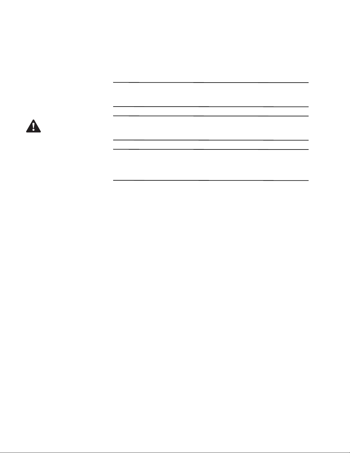
ATTENTION Possible bodily in jury – Do not install any DE6600 drive tray or
E2660 controller-drive tray in the top of the cabinet over your head. A fully-populated
DE6600 drive tray or E2660 controller-drive tray weighs 100 kg (220 lb).
WARNING (W15) Risk of bodily injury – An empty tray weighs approximately
56.7 kg (125 lb). Three persons are required to safely move an empty tray. If the tray
is populated with components, a mechanized lift is required to safely move the tray.
ATTENTION Possible address conflict or loss of data access – To prevent address
conflicts and loss of data access, replace all components in the same tray and in the
same location in the tray. Reinstall all trays in their original locations in the cabinet.
Reinstall all cables in their original locations in the cabinet.
1. Reinstall all of the trays in their original locations in the cabinet.
2. Reinstall all of the components in their original locations in the trays.
3. Reinstall all cables to their original locations in the trays.
4. Route the interface cables to the cabinet.
5. Route the main power cords from the cabinet to the two external power sources.
Do not plug in the power cords at this time.
Installing the Cable Spools and the Tie Wraps
16 Model 3040 40U Cabinet Installation
Install the cable spools and the tie wraps along both sides of the vertical power
distribution outlets. The cable spools and the tie wraps accommodate excess cable
length and cable routing for the controllers and the trays.
The cable spools are shipped with the controller-drive trays.
Page 23
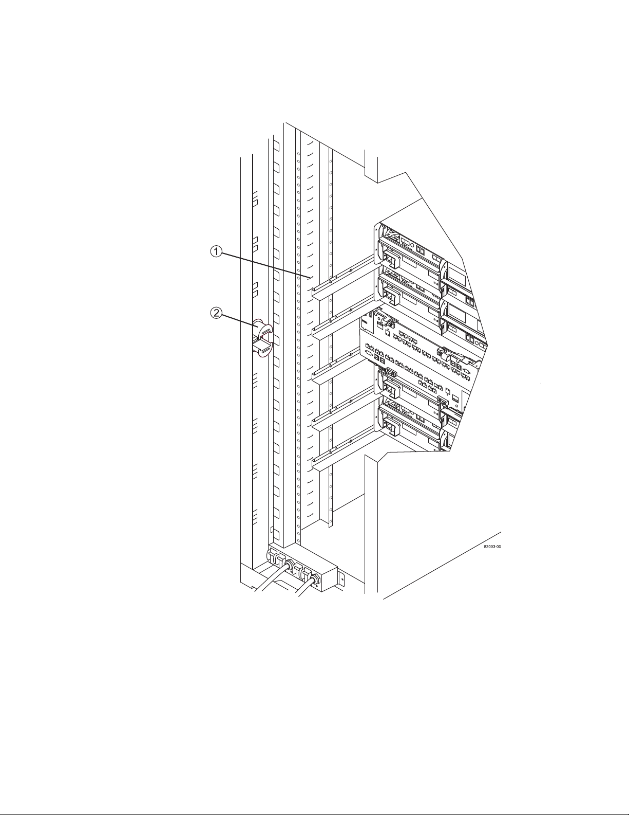
Figure 4 Tie Wrap Locations and a Cable Spool
1. Tie Wrap Location
2. Cable Spool
Chapter 3: Completing the Installation 17
Page 24

Installing Other Components
1. If you have additional trays that must be installed, install the mounting hardware
for these trays. See “Installing the Cable Spools and the Tie Wraps” on page 16.
2. If the front of the cabinet is not completely filled with trays, use front panel kits
to cover the empty spaces above or belo w the installed trays. Co v ering the empty
spaces is necessary so that the correct airflow through the cabinet is maintained.
3. Refer to the controller-drive tray installation guides for the trays that are
contained in the cabinet, and complete the power-on procedures described in the
guides.
18 Model 3040 40U Cabinet Installation
Page 25
Installing Additional Mounting Rails
If you are installing controller-drive trays or drive trays that were shipped separately
(not already installed in the cabinet), you might need to install additional mounti ng
rails in the cabinet.
1. Determine the location for the mounting rails.
— Above an existing tray – Position the mounting rails immediately above the
top tray in the cabinet.
— Beneath an existing tray – Position the mounting rails with enough
clearance to hold the tray being installed: 8.9 cm (3.5 in.) for 2U drive trays
or controller-drive trays, 13.3 cm (5.25 in.) clearance for 3U drive trays or
controller-drive trays, or 17.8 cm (7 in.) clearance for 4U controller-drive
trays or drive trays.
2. Use the measurement markers on the right-front and left-front vertical supports to
attach the mounting rails to the same position on each side of the cabinet.
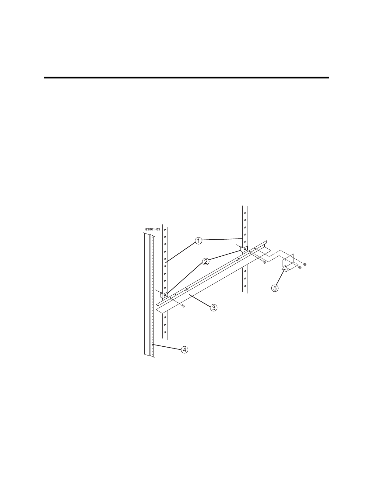
Figure 5 Mounting Rails
4
1. Vertical Support
2. Clip Nut
3. Mounting Rail
4. EIA Support Rail
5. Mounting Clip
Chapter 4: Installing Additional Mounting Rails 19
Page 26

3. Position the clip nut on the vertical support at the front of the cabinet.
4. Place the mounting rail on the vertical support, as shown in Figure 5 on page 19.
5. Align the mounting rail holes in front of the holes in the vertical support.
6. Position the clip nut on the vertical support at the rear of the cabinet.
7. Place the mounting rail on the vertical support.
8. Align the mounting rail holes in front of the holes in the vertical support.
9. Attach a 10-32x1/2 screw to the front clip nut. Tighten the screw.
10. Attach a 10-32x1/2 screw to the rear clip nut. Tighten the screw.
11. Repeat step 3 through step 10 to attach and level the second mounting rail on the
other side of the cabinet.
12. On the EIA support rail at the front of the cabinet, position a clip nut to align with
the mounting holes on the front face of the tray that you are installing.
13. Attach a 10-32x1/2 screw to the clip nut on the EIA support rail. Tighten the
screw.
14. Repeat step 12 through step 13 to secure the front of the other side of the tray.
15. Install each tray using the applicable tray installation instructions.
16. Is the cabinet completely filled with trays?
— Yes – Refer to the initial setup guide for each tray that is contained in the
cabinet, and complete the power-on procedures described in the guides.
— No – Use front panel kits to cover the empty spaces above or below the
installed trays.
20 Model 3040 40U Cabinet Installation
Page 27
Turning on the Power with 72A PDUs
83002-05
2
1
Power to trays is provided by a standard A C power source. This topic describes using
72A power strips to provide up to 72A of usable power through six 12A banks of
power.
NOTE While the trays perform the power-on procedure, the LEDs on the front and
the rear of the trays blink. Depending on your configuration, it can take several minutes
to complete the power-on procedure.
1. Turn off the power to all of the components in the cabinet.
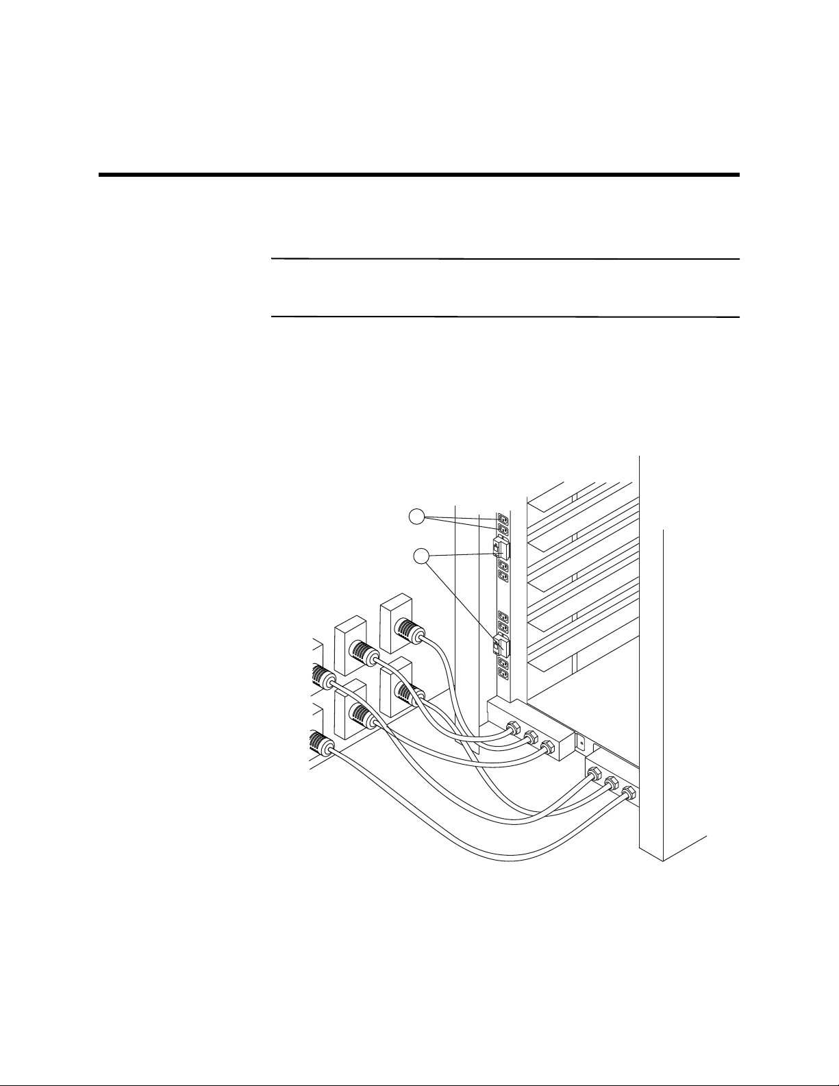
2. Turn off all 12 circuit breakers to their off (down) position.
3. Plug each of the six L6-30 plugs (USA and Canada) or IEC 309 plugs
(worldwide, except for USA and Canada) into the available electrical outlets.
4. Turn all 12 circuit breakers to their on (up) position.
Figure 6 Circuit Breakers and Electrical Outlets – 72A PDUs
5
1. Circuit Breakers
2. Electrical Outlets
Chapter 5: Turning on the Power with 72A PDUs 21
Page 28

5. Turn on the power to all of the drive trays in the cabinet (refer to the individual
initial setup guides for assistance).
NOTE Wait 30 seconds after turning on the drive trays be fore you turn on the power
to the controller-drive trays.
6. Turn on the power to all of the controller-drive trays in the cabinet (refer to the
individual initial setup guides for assistance).
22 Model 3040 40U Cabinet Installation
Page 29

Regulatory Compliance Statements
FCC Radio Frequency Interference Statement
Laser Products Statement
This equipment has been tested and found to comply with the limits for a Class A
digital device, pursuant to Part 15 of the Federal Communications Commission (FCC)
Rules. These limits are designed to provide reasonable protection against harmful
interference in a commercial installation. This equipment generates, uses, and can
radiate radio frequency energy and, if not installed and used in accordance with the
instructions, may cause harmful interference to radio communications. Operation of
this equipment in a residential area is likely to cause harmful interference, in which
case the user will be required to correct the interference at his/her own expense.
NetApp, Inc. is not responsible for any radio or television interference caused by
unauthorized modification of this equipment or the substitution or attachment of
connecting cables and equipment other than those specified by NetApp. It is the user’s
responsibility to correct interference caused by such unauthorized modification,
substitution, or attachment.
This equipment uses Small Form-factor Pluggable (SFP) optical transceivers, which
are unmodified Class 1 laser products pursuant to 21 CFR, Subchapter J, Section
1040.10. All optical transceivers used with this product are required to be 21 CFR
certified Class 1 laser products. For outside the USA, this equipment has been tested
and found compliant with Class 1 laser product requirements contained in European
Normalization standard EN 60825 1:2007. Class 1 levels of laser radiation are not
considered to be hazardous and are considered safe based upon current medical
knowledge. This class includes all lasers or laser systems which cannot emit levels of
optical radiation above the exposure limits for the eye under any exposure conditions
inherent in the design of the laser products.
NetApp, Inc. is not responsible for any damage or injury caused by unauthorized
modification of this equipment or the substitution or attachment of connecting cables
and equipment other than those specified by NetApp. It is the user’s responsibility to
correct interference caused by such unauthorized modification, substitution, or
attachment.
Regulatory Compliance Statement FCC-1
Page 30

This Class A digital apparatus meets all requirements of the Canadian
Interference-Causing Equipment Regulations.
Cet appareil numérique de la classé A respecte toutes les exigences du
Règlement sure le matèriel brouilleur du Canada.
FCC-2 Regulatory Compliance Statement
Page 31

Page 32

Copyright © 2013 NetApp, Inc. All rights reserved.
 Loading...