

Page 1

LINKRUNNER
Smart Network Tester
™
G2
User Guide
May 29, 2019
Page 2

Legal Notification
Use of this product is subject to the En d User License Agreement avai lable at htt p://Net Ally .com/terms-and-conditions or
whi ch accompanies th e product at the ti me of shipment or, if
applicable, the legal agreement executed by and between
NetA lly, an d th e purchaser of this product.
Open-Source Software Acknowledgment: This product may
incorporate open-source components. NetAlly will make available source code components of th is product, if an y, at Lin k-
Live.com/OpenSource.
NetA lly reserves th e right , at its sole discretion, to make
changes at any t ime in it s techn ical information, specifications, service, and support programs.
2
Page 3

Contents
Contact Us 6
Introduction 7
About this Guide 8
Using the PDF Reader App 9
Most Commonly Used Features 10
Safety 11
Physical Features 13
Buttons and Ports 14
Power and Charging 17
Maintenance 19
Home and Android Interface 20
Swiping and Navigation 21
Home Screen 22
Top Notification P anel 24
Apps 27
Device Settings 29
Sharing 31
Saving a Screenshot 33
3
Page 4

LinkRunner G2 Application Settings 34
Left-Side Navigation Drawer 35
Configuring Test Settings 36
Profiles and Jobs 44
LinkRunner G2 Tests and Results 47
AutoTest 48
Floating Action Button 63
Switch Test 64
Cable Test 66
Link-Live Cloud Service 71
Getting Started in Link-Live 72
LinkRunner G2 Tools 75
Reflector 76
VLAN Monitor 79
Capture 81
Software Management 85
Managing Files 86
Updating Firmware 90
Restoring Factory Defaults 92
4
Page 5

Changing the Language 93
Additional Features 94
Camera and Flashlight 95
Wi-Fi Bluetooth USB Adapters 96
Specifications and Compliance 99
Specifications and Co mpliance 100
5
Page 6

Contact Us
NetAlly.com
NetAlly
2075 Research P arkway, SuiteA
Colorado Springs, CO 80920
For additional information and suppo rt, visit
NetAlly.com/products/LinkRunnerG2 and
NetAlly.com/Support.
Register your LinkRunner G2
Registering yo ur product with NetAlly givesyou
accessto valuable information o n pro duct
updates, troubleshooting procedures, and other
services.
To register your product, go to
NetAlly.com/Registration.
6
Page 7
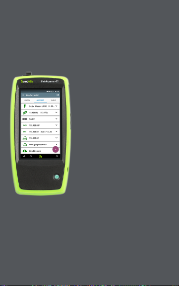
LinkRunner G2 User Guide
Introduction
The LinkRunner G2 is
an Android-based
network testing and
troubleshooting tool. It
allows networking
professionals to easily
verify network
connectivity and PoE
functionality and to
validate cabling.
LinkRunner G2 can also
act as a packet reflector
for performance tests
run by other NetAlly
testers.
7
Page 8

Introd uction
About this Guide
This User Guide covers all the LinkRunner G2
(LRG2) testing functionality and basicelementsof
the Android interface.This guide is meant for
users knowledgeable abo ut networking testing
operations.
8
Page 9

Introd uction
Using the PDF Reader App
A PDF reader application is pre-installed on your
LinkRunner G2 device to allow easy navigation of
this guide:
l Touch headings in the Contents listto skip
to the corresponding sections.
l Tap blue links to go to their destinations.
Underlined blue links open external
websites.
l Tap the screen once to show or hide the app
toolbars at the top and bottom of the
Adobe Reader screen.
l Tap the screen twiceto zoom in or o ut.
l Touch the outline icon in the upper tool
bar to view the guide outline and choose a
section to read.
l Also, touch the outline icon to accessany
bookmarks or comments you have saved.
l
Use the search feature to find specific
terms.
9
Page 10

Introd uction
Most Commonly Used Features
Touch the links below to skip to the instructions
for the features listed:
"AutoTest" o n page48
"Cable Test" o n page66
"Switch Test" on page64
"Configuring Test Settings" on page36
"Home Screen" on page22
"Reflector" on page76
"VLAN Monitor" on page79
"Capture" on page81
"Wi-Fi Bluetooth USB Adapters" o n page96
10
Page 11

Introd uction
Safety
Observe the following safety information:
Use only the AC Adapter provided or Power over
Ethernet to charge the battery.
Use the proper terminalsand cable for all connections.
To avoid possible electric shock or personal injury,
follow these guidelines:
l Do not use the product if it is damaged.
Before using the product, inspect the case,
and look for cracked or missing plastic.
l Do not o perate the pro duct around
explosive gas, vapor, or dust,
l There are no serviceable parts. Do not try to
service the pro duct.
l If this product isused in a manner not
specified by the manufacturer, the
protection provided by the product may be
impaired.
11
Page 12

Safety Symbols
Warning or Caution: Risk of
W
damage to or destruction of
equipment or s oftware.
X
Warning: Risk of elect rical s hock.
Not for connection to a public
j
telephone system.
Class 1 Laser Product. Do not
*
look into the laser.
Introd uction
12
Page 13
LinkRunner G2 User Guide
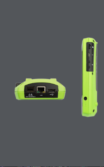
Physical Features
This User Guide section
illustrates the ports and buttons
on the LinkRunner G2 and
describes charging and
maintenance.
13
Page 14
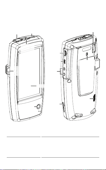
Touchscreen
USB Port
100/1000 BASE-X
Fiber Port
RJ-45 LAN
Port and
Trasmit
LEDs
RJ-45 Cable Test/
Wiremapping
(WMAP) Port
Micro USB
On-the-go
Port
Micro SD
Card Slot
Charging
Port
Kensington
Lock
Camera
and
Flash
Volume
Buttons
Microphone
Speaker
Power Button
and LED
Physical Features
Buttons and Ports
Button and port functions are described below.
Feature Description
100/1000 BASE-X
Fiber Port
Connects to an SFP adapter and
fiber cable
Supports 100BASE-FX and
1000BASE-SX/LX/ZX
14
Page 15

Feature Description
USB Port
RJ-45 LAN Port
(10/100/1000
BASE-T)
Transmit LEDs
Cable Test/Wire
Mapping Input
(WMAP)
Power Button
and LED
Charging Port
Mic rophone
Camera and
Flash
Mic ro SD Card
Slot
Mic ro USB Onthe-Go Port
Connects to any USB device
Connects to the network using
an Ethernet cable
Charges the unit if PoE is
available
Green LED lit: Linked
Yellow LED flashing: Activity
Used for patch cable testing
Glows gr een when the unit is
powered on
Glows red when the unit is
charging
Connects to ACadapter for
charging
Allows voice input
Captures images and acts as a
flashlight
Used for removable storage
expansion
Connects to a USB On-the-Go
cord for communicating with a
PC or USB peripheral
15
Physical Features
Page 16

Feature Description
Kensington
Lock
Volume Butt ons
Speaker
Allows youto lock your unit
Increase or decrease the audio
volume
Produces audio
16
Physical Features
Page 17

Physical Features
Power and Charging
The LinkRunner G2 containsa rechargeable
Lithium Ion battery.You can charge your LR G2
using either AC or Power over Ethernet (PoE). The
LinkRunner G2 does not charge via the USB port.
See Buttons and Ports.
Charging
To charge with AC power, plug the included AC
adapter into an AC outlet,and connect it to the
charging po rt on the device.
To charge with PoE, connect the RJ-45 port o n the
device to a network switch with P oE availableor
with a PoE injector.
NOTE:To charge via PoE, the LR G2 must be
powered on or in sleep mode, and PoE must be
enabled in the testsettings.
Charge the battery for 4-6 hours before first use.
Powering On
l Press the power button on the front of the
unit to power on the LinkRunner G2.
17
Page 18

Physical Features
l When the unit ison, press the power button
to put it in sleep mode.
l To shut down, hold the power button for
one second until the “Power off” dialog bo x
appears on the touchscreen, then tap
Power off .
l To perform a hard power off (without
shutting down the software), pressand hold
the power button for five seconds.
The first time you turn it on, the LinkRunner G2
testing application opens and begins testing your
network immediately. Co nnect the top RJ-45LAN
port or 100/1000 BASE-X Fiber port to an active
network to begin receiving test results.
18
Page 19

Physical Features
Maintenance
To clean the display, use a lens cleaner and a soft,
lint-free cloth.
To clean the case,use a soft cloth that is moist with
water or a weak soap.
WCAUTION: Do not use solventsor abrasive
materials that may damage the product.
19
Page 20

LinkRunner G2 User Guide
Home and Android Interface
This section explains how to use the
features of the And roid home screen and
user interface to navigate and organize
your device.
The LinkRunner G2 interface applies
many of the operations typical of any
Android device. Use swiping touchscreen
motions to navigate through screens and
to drag d own the top notification panel.
20
Page 21

Home and Andro id Interface
Swiping and Navigation
The navigation actions you can perform to move
through screens and panelsin LinkRunner G2 are
the same as those you would use to navigate an
Andro id phone or tablet.
Swiping
Touch and drag your finger or "swipe" up, down,
left, and right to move through pages of the
Home Screen and LinkRunner G2 testing application, scroll up or down in long screens,and pull
out navigation drawers and panels.
Long Pressing
Touch and hold or "long press" files or application
icons to reveal additional operations. For
example, you can long press a file name in the File
Manager Application to show options for mo ving
or sharing the file.
21
Page 22
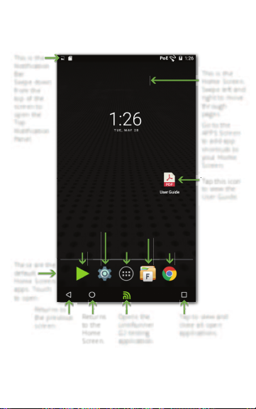
Home Screen
Tap this icon
to view the
User Guide.
Ta
This is the
Notification
Bar.
Swipe down
from the
top of the
screen to
open the
Top
Notification
Panel.
These are the
default
Home Screen
apps. Touch
to open.
NetAlly
App Store
Device
Settings
APPS
Screen
Web
Browser
File
Manager
This is the
Home Screen.
Swipe left and
right to move
through
pages.
Go to the
APPS Screen
to add app
shortcuts to
your Home
Screen.
Returns to
the previous
screen.
Tap to view and
close all open
applications.
Returns
to the
Home
Screen.
Opens the
LinkRunner
G2 testing
application.
Home and Andro id Interface
22
Page 23

Home and Andro id Interface
Notification Bar
The Notification Bar acrossthe top of the screen
displaysnotification icons from the Android
system as well as the following LinkRunner G2
specificicons:
indicates accessto Power over Ethernet for
power and charging.
indicates that a wired Ethernet connection is
established.
Touch and swipe down on the Notification Bar to
open the Top Notification Panel.
23
Page 24
Home and Andro id Interface
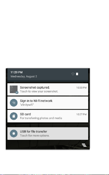
Top Notification Panel
The Top Notification Panel contains notifications
from your device, such as do wnloaded and
installed applications, inserted hardware, captured
screenshots, and available updates.
Swipe (touch and drag) down from the very top
of the LinkRunner G2 screen to slide down the
notification panel.
24
Page 25
Home and Andro id Interface
l Touch a notification to open the related app,
image,device options, or perform o ther
actions.
l Swipe left on a no tification to dismiss it.
l
Touch the icon at the lower right of the
panel to dismiss all notifications.
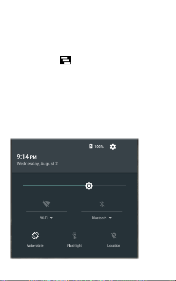
Quick Settings Panel
The Quick Settings Panel is also accessed by
swiping down from the top of the screen. You can
either swipe down twice,or touch the dark grey
top portion of the notification panel to open it.
25
Page 26

Home and Andro id Interface
Touch an icon in the panel to enable or disablethe
corresponding feature. See Wi-Fi Bluetooth USB
Adapters for more information on using the
optional Wi-Fi and Bluetooth adapter accessory.
26
Page 27
Home and Andro id Interface
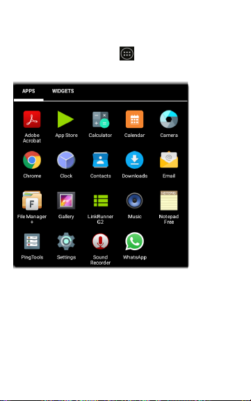
Apps
Touch the APPS button on the Home Screen
to open the APPS screen.
Swipe left or touch WIDGETS to view the WIDGETS
screen.
Touch and hold (long press) an application's icon
or a widgetto add it to the Home Screen.
27
Page 28

Home and Andro id Interface
App Store
From the Home Screen or APPS Screen, open the
NetAlly App Store to d ownload Android
applications specifically chosen to work with the
LinkRunner G2 tester.
Touch the
search icon to
search for an
App.
To request that an App be added to the
App Store, visitthe Apps page at
Link-Live.com, and selectthe Floating
Action Button (FAB) at the lower right corner to
Request an App.
28
Page 29

Home and Andro id Interface
Device Settings
To accessthe Android device settings, touch the
Settings icon o n the Home Screen.
Use the device Settingsscreen to adjustthe
LinkRunner G2 display, sound, date/time, and
language,view installed applications and memory
devices, update your software, or resetto factory
defaults.
29
Page 30

Home and Andro id Interface
Auto Power Off
Activating the Device Auto Power Off function
helps to extend the LR G2's battery run time. The
default Auto Power Off setting isNever.
1. From the device Settings , select Di splay.
2. On the Display settingsscreen, touch Device
auto power off.
3. In the pop-up dialog box, select how long
you want the LR G2 to remain On with no
activity occurring. The LR G2 will
automatically po wer off after the selected
period of inactivity has passed.
You can also adjust the setting that controls when
the LR G2 goes into Sleep mode from the Display
settingsscreen.
30
Page 31

Home and Andro id Interface
Sharing
LinkRunner G2 allows you to “share” images and
files like you would on an Android smart phone.
When yo u see the Share icon , touch it to view
your configured sharing options.
This example shows a captured screenshot notification fro m the Top Notification Panel.
Touching SHARE opens the “Share with”pop-up
dialog, where you can chose a sharing method,
such as email, messaging, or uploading to LinkLive.
31
Page 32

Home and Andro id Interface
Sharing Files to Link-Live
From the “Share with” dialog box, touch the
LinkRunner G2 o ption to share a file to Link-Live
Cloud Service along with your last test result or
individually to the Uploaded Filespage in LinkLive.
32
Page 33

Home and Andro id Interface
Saving a Screenshot
On the LinkRunner G2, pressand hold the Power
button and the Vol ume Down button at the
same time for one second to save a screenshot of
the current screen. (See Buttons and Ports for
button locations.)
The LinkRunner G2 emits a beep and displays the
captured screenshot notification in the Top Noti-
fication P anel when it issuccessful.
33
Page 34

LinkRunner G2 User Guide
LinkRunner G2 Application Settings
This chapter
describes the
process for
configuring
test settings
and saving
them to a
profile.
34
Page 35

Once claimed to
Link-Live, the
unit’s name and
organization
display here.
Tap here to open
the Profiles
screen.
Tap here to open
the Settings
screen.
Tap here to enter
a new Job
comment.
Tap here to use
the Reflector
tool.
Tap here to view
information
about your unit.
Tap here to use
the VLAN
Monitor tool.
Tap here to use
the Packet
Capture tool.
LinkRu nner G2 Application Settings
Left-Side Navigation Drawer
To accessthe LinkRunner G2 testing application
settings, touch the navigation menu icon at the
top left of the LinkRunner G2 application screen.
35
Page 36

LinkRu nner G2 Application Settings
Configuring Test Settings
The LinkRunner G2 settingsallow you to customize test settings for PoE, Speed/Duplex,
Security, IP configuration, test targets,and other
aspectsof AutoTest, Switch Test, and Cable Test.
To configure testing for your network, touch the
navigation menu icon at the top left of the
LinkRunner G2 application screen, and then touch
the option.
Saving and Loading Profile Settings
The header o n the Settings screen displays the
name of the current Profile.
To save yo ur settings to a Pro file(and viewother
options), tap the save icon at the top right of
the Settings screen.
36
Page 37

LinkRu nner G2 Application Settings
To keep your revised settings without saving them
to a profile, touch the back arrow icon to the left of
the Settings screen header. Your new settingsare
applied, and an asterisk * is added to the profile
name to indicate unsaved changes.
See Profilesand Jobs for more o n pro files.
Test Setting Descriptions
37
Page 38

LinkRu nner G2 Application Settings
PoE
Enable PoE: Slide the toggle switch right to enable
the PoE testportion of AutoTest, and slide left to
disableit.
Class: Touch the down caret to the right of the
field to selecta Po E classsetting to match your
switch's(or PoE injector's) available class.The
LinkRunner G2 supports Cisco's UP OE, which can
prov ide up to 51 W, as well as 802.3bt classes5-8.
Select the Injector o ption if you are using a no nIEEE injector.
NOTE:LR G2 may not receive the total wattage
advertised by your switch or injector because of
power loss over the cable.
LLDP: This field appears if Class 4 (25.50 W) is
selected. Class4 LLDPmust be enabled on the
switch for AutoTestto detect it successfully.
NOTE:I f a switch does not support LLDP and the
LLDP setting is enabled on LR G2, LLDP negotiation will fail, but it will no t affect the restof the
AutoTest.
Request Pow er (W): This field appears if the
UPOE classis selected. Touch the field to open a
38
Page 39

LinkRu nner G2 Application Settings
pop-up keybo ard and enter the requested
wattage.
Enable TruePower™: Slide the toggle switch right
to enable the TruePower feature. TruePower validatesthat the Switch (PSE) and cabling can
prov ide the requested power under load.
Connect
Speed/Duplex: Selectthe speed and duplex
option that you want to test your network against.
The defaultis Auto negotiation.
Security
802.1X Authentication: Slide the toggle switch
right to enable 802.1Xauthentication.
EAP Type: This field appears if 802.1X authentication is enabled. Touch the down arrow to
choose the correct type. Additional security fields,
such as Username and Password, display as
required.
IP
IPv6: Slide the toggle switch right to enable IPv6.
39
Page 40

LinkRu nner G2 Application Settings
IP Configuration: Touch the down caret to
switch between DHCP and StaticIP configuration.
If you choose static, the IP Address,Subnet Mask,
and other IP fields display. Touch each field to
open a pop-up number pad and enter the
addressesas needed. Touch OK to save them.
DHCP Option: Slide the toggle switch right to
selectOption 150, 43, or 60.Options 43 and 150
request the IP address of a key server, such as a
VoI P TFTP server or WirelessLAN Controller.
Option 60 allowsthe user to enter a Vendor Class
Identifier string, which informs the DHCP server of
the type of client.
Proxy: Slide the toggle switch right to enable
Proxy settings.When pro xy is enabled, the
Address, Po rt, Username, and Password fields
appear. Touch each field to open a pop-up
keyboard and enter the appropriatedata. Touch
OK to save your entries.
Targets
You can add an unlimited number of test targets
by entering the IP address or a URL and specifying
either an ICMP Ping or TCP Port Open test for
each target.
40
Page 41

LinkRu nner G2 Application Settings
Address: When AutoTest runs, the LinkRunner
G2 attempts to reach the target address entered in
this field.The default is Google.com.
l Touch the Address field to open a pop-up
keyboard and enter a new address.
l Touch the action overflow icon to the right
of the Address field to either Delete the
targetaddress field fro m AutoTest or
Dupli cate the current target address entry.
Port: This is the port the LinkRunner G2 usesto
connect to the targetaddress for a TCP Port Open
test. The default is 80. Touch the Po rt field to open
a pop-up number pad and enter a new port
number. Touch OK to save it.
Ping: Slide the toggle switch right to run an ICMP
Ping test to the target address. The Port field disappears when this toggleis enabled.
+ ADD TARGET: Touch to add additional target
address fields.
Test
Stop After: This setting directsAutoTestto stop
testing after the selected test step.The excluded
test cards will no t appear on the AutoTest screen.
41
Page 42

LinkRu nner G2 Application Settings
Link-Live: Slide the toggle to the leftto disable
uploading of AutoTest results to Link-Live and
remove the Link-Live Upload card from the
AutoTest screen.
VLAN
Enable VLAN: Slide the toggle to the right to
enable VLAN settings.Once enabled, VLAN ID and
VLAN Priority fields appear. Touch these fields to
open a pop-up number pad and enter the correct
ID and priority. Touch OK to save them.
NOTE:W hen VLAN is enabled, the VLAN Testcard
appears on the AutoTest screen.
User Defined MAC
Enable User Defined MAC: Slide the toggle to the
right to enable a user-defined MAC address.W hen
enabled, the User Defined MAC field turns from
grey to black.
User Defined MAC: If enabled, touch thisfield to
open a pop-up keyboard and enter your MAC
address.Touch OK to save it.
42
Page 43

LinkRu nner G2 Application Settings
General Settings
Cable Unit: Touch the down caret to select
either meters or feet for the Cable Test unit of
measurement.
Default Setti ngs: Tap thisfield to restore the
LinkRunner G2 testing application to factory
default pro filesettings.A dialog box willask you to
confirm Yesor No before it restores.
NOTE:See Restoring Factory Defaults for instruc-
tions on resetting yo ur entire LR G2 device to
factory default configuration.
43
Page 44

LinkRu nner G2 Application Settings
Profiles and Jobs
A Profile is a saved configuration of testsettings.
The currently active Profile'sname is displayed in
the Left-Side Navigation Drawer and at the top of
the Settings screen, as shown below.
The header o n the Settings screen displays the
name of the current Profile.
An asterisk * next to the Profile name indicates
that yo u have adjusted settingssince the Pro file
waslastsaved.
To save yo ur settings to a Pro file(and viewother
options), tap the save icon atthe top right o f
the Settings screen.
Profile saving options include the following:
l Save savesthe current settingsto the
currently loaded profile.
l Save As savesa new Profile with the current
settingsand opens a pop-up keyboard for
44
Page 45

LinkRu nner G2 Application Settings
entering a new name. Touch SAVE to save
the new Profile Name.
l Load opens the Profiles screen.
Profiles Screen
This screen displays a listo f allthe saved Profiles.
NOTE:The "Link-Live" pro fileis a profile created
from Link-Live Cloud Service and downloaded to
LinkRunner G2. A single profilecan be created in
Link-Live and pushed to many LinkRunner G2s.
Touch a Profile's name to load itssaved settings.
Touch the overflow action icon next to a Profile
name to Delete, Rename, or Duplicate it.
If you choose to duplicate a Profile,a pop-up
dialog prompts you for a New Profile Name.
Touch SAVE to save the new name.
45
Page 46

LinkRu nner G2 Application Settings
Jobs
Jobs are comments that are added to the test
resultsuploaded to Link-Live Cloud Service. They
help you organize testresults.
To save a Job comment, touch the navigation
menu icon at the top left of the LinkRunner
G2 application screen, and then touch the Job
field to open a dialog box and the pop-up
keyboard. Touch OK to
save the new Job
comment.
If the Job saved on your
LinkRunner G2 unit
matchesa named folder
in your Link-Live
organization, the test resultsare automatically
sorted into that folder.
If you want to create a new folder in Link-Live and
save your test resultsto it,simply add a forward
slash / at the beginning of the Job name, as shown
in the image on this page.
46
Page 47

LinkRunner G2 User Guide
LinkRunner G2 Tests and Results
The LinkRunner
G2 features a
main AutoTest
screen, a Switch
Test screen, and a
Cable Test screen.
Swipe left and
right to move
through the three
test screens.
This User Guide
chapter describes
each test section
and its results.
47
Page 48

LinkRu nner G2 Tests and R esults
AutoTest
AutoTest is a set of wired testsand measurements
that run automatically when you turn o n your
LinkRunner G2. To run AutoTest with your unit
already powered on, connect the RJ-45 port or the
Fiber port on the top of the LinkRunner G2 to an
active network switch. Touch the NetAlly logo at
the bottom of the screen to open the LinkRunner
G2 testing app.
Each individual test
is presented o n its
own card. Tap the
down caret on
the right side o f a
card to expand and
view detailed
results.
The AutoTesttab
header shows the
number of failed
tests (if any) in red
and the number of
warnings in yellow.
In the image, the
48
Page 49

LinkRu nner G2 Tests and R esults
Link test has a warning, and the DNS test has
failed. The testicons also turn green, yellow,or red
based on the test results.
To restart testing at any time, tap the refresh icon
at the top right of the LR G2 app screen.
TestSettings are described in the LinkRunner G2
Application Settings chapter.
The following subsections describe each card in
the AutoTest.
49
Page 50

LinkRu nner G2 Tests and R esults
Power over Ethernet (PoE) Test
The header o f the PoE Testcard displays the
measured Voltage, Class, and W attage.
The PoE card displays additional TruePower™
resultsonly if TruePower is enabled in the
PoE Settings. TruePower appliesa load equivalent
to the selected classto mimic a Powered Device
(PD).
50
Page 51

LinkRu nner G2 Tests and R esults
Detailed PoE Results
PoE Result Description
Requested
Class
Received Cl ass
TruePower™
Power
Unloaded
Voltage
TruePower™
Voltage
PSE Type
Spare Pair
Negotiation
Positi ve
Negative
Class selected in the PoE test
settings
Class acknowledgment received
by the LR G2 from the switch
Measured wattage with load
Measured voltage without load
Measured voltage with load
Switch's advertised Power
Sourcing Equipment (PSE) type.
Recognizedtypes are 1 – 4,
LTPoE++, Cisco UPOE, and PoE
Injectors. PSEs supporting UPOE
are classified under Type 2. If the
type cannot be determined, 1/2
is displayed.
Status of spare pair negotiation
for UPOE (true or false)
Negotiation type for UPOE and
Class 4 (UPOE or LLDP)
Positive PoE cable pair IDs
Negative PoE cable pair IDs
51
Page 52

LinkRu nner G2 Tests and R esults
Link Test
The Link Test card header displays the advertised
speed and duplex in grey and the detected speed
and duplex in black text.
If the Link icon turns yellow as shown on page48,
LR G2 has detected a downshift from the
maximum advertised speed.
Detailed Link Results
Link Result Description
Advertised Speed
Speed capability as reported
by the switch
52
Page 53

LinkRu nner G2 Tests and R esults
Link Result Description
Actual Speed
Advertised
Duplex
Actual Duplex
Rx Pair
Polarity
Interface
Link speed as measured by
LinkRunner G2
Duplex capabilities reported
by the switch
Duplex in use as detected by
LR G2
Link receive pair
Link polarity: normal or
reversed
Link interface: Copper/RJ-45
port or SFP/Fiber port
53
Page 54

LinkRu nner G2 Tests and R esults
VLAN Test
The VLAN Testcard only appears if VLAN is
enabled in the LinkRunner G2 Application settings
or if VLAN-tagged traffic is detected during
AutoTest.
Detailed VLAN Results
VLAN Result Description
VID
PRI
Seen
VIDs
VLAN ID selected in the LR G2
Application settings
VLAN Priority set in the LR G2
Application settings
Number of VLANs detected
during AutoTest
VLAN IDs detected during
AutoTest
54
Page 55

LinkRu nner G2 Tests and R esults
Switch Test
The Switch Test card header displays the discovered switch name o r simply "Ethernet" if no
switch name could be discovered.
If LinkRunner G2 wasunable to obtain switch
information from the first AutoTestrun, touch
REFRESH to capture and display the next port
advertisement/xDP (LLDP or CDP).
Detailed Switch Results
Switch Result Description
Port
VLAN
Discovered port name
Discovered VLAN ID number
55
Page 56

LinkRu nner G2 Tests and R esults
Switch Result Description
Voice VLAN
Name
Model
Address
Type
Discovered Voice VLAN ID
number
Discovered switch's name
Discovered switch's model
Discovered switch's IP address
Switch type: CDP or LLDP
56
Page 57

LinkRu nner G2 Tests and R esults
DHCP Test
The DHCP Test card header displaysthe DHCP
server's IP address.
Detailed DHCP Results
DHCP Result Description
Discover
Offer time
Status of the discovery frame
broadcast fr om LRG2
Time between when LR G2
sent the discovery and
received an address offer
from the DHCP server
57
Page 58

LinkRu nner G2 Tests and R esults
DHCP Result Description
Request
ACK Time
Server
Subnet
Option 150/43
Lease Time
Status of the address request
sent fr om LRG2
Time between LRG2 sending
the r equest and receiving the
acknowledgement from the
DHCP Server
IP address of the DHCP server
IP address of the subnet
where LR G2 is testing
IP address returned by the
DHCP server if a DHCP option
is enabled in the test settings
Time the IP address is leased
to the LR G2 by the DHCP
server
58
Page 59

LinkRu nner G2 Tests and R esults
DNS Test
The DNS test card header displays the DNS IP
addresses.
Expand the DNS card to view the response times
from each DNS server. The LR G2 pings each DNS
server three times and displaysthe response time
from each Ping. Up to four DNS servers are
captured and displayed on the DNS test card.
59
Page 60

LinkRu nner G2 Tests and R esults
Gateway Test
The Gateway Test card displays the gateway's IP
address.
The LR G2 pings the gateway three times and
displaysthe response time from each P ing.
Touch CONTINUOUS to run a continuous mon-
itoring test to the gateway. A dialog box appears
and displays the continuous Ping testresults until
you close the dialog box.
60
Page 61

LinkRu nner G2 Tests and R esults
Target Tests
The Targets Testsare user-assignable endpoints
that LR G2 attempts to connectto each time
AutoTest runs. Target testsare either Ping or TCP
Port Open tests.
See Targets in the Configuring TestSettings
chapter.
The TargetTestcard header shows the URL or IP
address of the target and the port number if
applicable.
The expanded Target Test card shows the IP
address of the target,the type o f test (Ping or
61
Page 62

LinkRu nner G2 Tests and R esults
TCP), and the time for each response received by
LR G2.
Touch CONTINUOUS to run a continuous mon-
itoring test to the target.A dialog box appears and
displaysthe continuous Ping or TCP Port Open
test results untilyou close the dialog box.
Link-Live Upload
The Link-Live test card indicates whether the
LinkRunner G2 wasable to upload your test
resultsto the Link-Live Cloud Service. Refer to the
chapter on Link-Live Cloud Service for more
information.
62
Page 63

LinkRu nner G2 Tests and R esults
Floating Action Button
The Floating Action Button or FAB appears on
many of the Android and LinkRunner G2 application screens.It offers additional actions related to
the current screen or test.
Tap or click the FAB
once to view the additional options available.Then, touch the
pop-up button for the
action you want to
perform.
For example,the
AutoTest FAB allows
you to add a picture or a comment to the last
AutoTest result, which is automatically uploaded
to Link-Live at the completion of each test.
63
Page 64

Switch Name
and Model
Switch IP address
Port and slot number
Port VLAN IDs
Switch Test FAB
Sw
Speed and Duplex:
Advertised/Detected
Sp
Ad
PoE Voltage and
Wattage:
Advertised/Detected
PoE Positive and
Negative cable pairs
Blue line for Copper/LAN
Orange line for Fiber/SFP
LinkRu nner G2 Tests and R esults
Switch Test
The Switch test tab displaysthe information from
the nearestswitch by locating the port adv ertisement (xDP) o n the firstfew packets seen by
LinkRunner G2.
64
Page 65

LinkRu nner G2 Tests and R esults
Tap the FAB on the Switch
test screen to access the
following actions:
Refresh xDP: Captures
and displays the next port
advertisement (CDP or
LLDP).
Flash Port: Causesthe
switch to flash the LED on the port where the
LinkRunner G2 isconnected.Touch and drag the
slider between Slow and Fast to differentiate it
from the other switch port LED flash rates.
To restart testing at any time, tap the refresh icon
at the top right of the LR G2 app screen.
65
Page 66

LinkRu nner G2 Tests and R esults
Cable Test
The Cable testcan help y ou determine cable
length and status,wire map patch and structured
cabling, and locatecables.The Cable test tab can
perform testsusing the configurations described
in thissection.
With an unterminated cable test, you can determine length, shorts, and splitsand locateopens.
With a terminated cabletestusing the internal
Wire Mapping Port or a WireView accessory, you
can identify cablelength, shorts and opens, split
pairs, crossover cables, and normal or negative
pair polarity.
NOTE:LR G2 cannot perform a cable teston a
cablethat is connected to a switch.
To restart testing at any time, tap the refresh icon
at the top right of the LR G2 app screen.
Refer to Buttons and Ports as needed.
66
Page 67

LinkRu nner G2 Tests and R esults
Open Cable TDR Testing
Connectan open cable (unterminated) into the
top RJ-45 port to m easure its length and view any
shorts, opens, or splits.
67
Page 68

LinkRu nner G2 Tests and R esults
Patch Cable Testing
Connecta cable fro m the top LinkRunner G2 RJ-45
LAN port into the side RJ-45 Cable Test/Wire
Mapping P ort to view its length and wire mapping,
including any faults.
68
Page 69

LinkRu nner G2 Tests and R esults
Wire Mapping
Connectthe top RJ-45port to a cable terminated
with an external WireView Cable ID accessory. A
WireView #1 is included with your LinkRunner G2.
Additional W ireViews2-6 are available for
purchase.
The Wire Mapper Cable Testdisplaysthe number
of the W ireView attached, unlessa cable fault
prevents LR G2 from detecting the WireView.
A cable/drop po rt can be traced using a WireView
up to 300 ft/100 m from the LinkRunner G2.
69
Page 70

LinkRu nner G2 Tests and R esults
Using the Tone Function
You can also tracea cable using a Fluke Networks*
IntelliTone™ Probe, or any analog probe, and the
Tone function.
Connecta cable into the
top RJ-45 port, touch the
FAB, and selectthe
appropriate Tone
option for your probe.
The LinkRunner G2
emitsthe tone through
the cable, and the probe
detects it, allowing you
to tracethe wire or locate it in the switch closet.
* IntelliTone is a trademark of Flu ke Networks.
70
Page 71

LinkRunner G2 User Guide
Link-Live Cloud Service
Link-Live
Cloud Service
is a free,
online system
for collecting,
tracking,
organizing,
and reporting your test results, which are
automatically uploaded once your
LinkRunner G2 is claimed.
Claiming your LR G2 to Link-Live also
allows you to update the firmware on your
unit and access applications in the
NetAlly App Store that have been
specifically chosen to work with
LinkRunner G2.
71
Page 72

Link-Live Cloud Service
Getting Started in Link-Live
To start, create a user account at Link-Live.com,
and sign in.
On the LinkRunner G2 Unit
In the LinkRunner G2 testing application on your
LR G2 unit, touch the navigation menu icon at
the top leftof the screen, and touch CLAIMNOW
in the navigation drawer.
In Link-Live
The first time you sign in to Link-Live, a pop-up
window appears, pro mpting you to claim a device.
If you already have a user account and other
devicesclaimed to Link-Live, navigateto the Units
page fro m the leftside navigation drawer, and
72
Page 73

Link-Live Cloud Service
click the Claim Unit button at the lower
right corner of the screen.
Then, select the LinkRunner G2 image,
and follow the claiming instructions on the LinkLive website.
Once your LR G2 is claimed to the Link-Live Cloud,
it willautomatically upload your AutoTest results
each time you run AutoTest.
From the LR G2, you can also upload a test
comment and a picture with your test results
using the AutoTest FAB and automatically sort
your resultsinto folders in Link-Live using the Jobs
feature.If your LR G2 is not connected to an active
network, the test result and any photos or
comments are stored in memory and uploaded
once a connection is established.
For more information on how to use Link-Live,
click or touch the navigation menu icon at the
top left of the Link-Live website,and select
.
73
Page 74

Link-Live Cloud Service
Unclaiming
To unclaim your LR G2 from Link-Live on the
device,open the About section from the Left-Side
Navigation Drawer, and selectUNCLAIM.
74
Page 75

LinkRunner G2 User Guide
LinkRunner G2 Tools
The LR G2 also features a performance
test Reflector, a VLAN Monitor, and
packet Capture tools. These are explained
in the following section.
Access the tools from
the Left-Side
Navigation Drawer.
75
Page 76

LinkRu nner G2 Tools
Reflector
The Reflector feature allowsthe LinkRunner G2 to
actas a reflector for performance testsconducted
by other NetAlly testing devices.
To open the Reflector screen, touch the navigation
menu icon at the top left of the LinkRunner G2
application screen, and then touch Reflector.
IP Address: When you enter the Reflector screen,
the LR G2 automatically obtains and displays itsIP
address in the top field. Use this IP address to
connect to the LR G2 from your main performance testing device.
76
Page 77

LinkRu nner G2 Tools
MAC Address: LinkRunner G2's MAC address
Packet Type: Touch the do wn caret to select
the packettype filter setting.The M AC + NetAlly
setting tellsLR G2 to reflect only packets with a destination MAC address that matchesthe LR G2's
own MAC address and NetAlly payload.
Swap: Touch the down caret to select a swap
setting.MAC + IP tells the LR G2 to swap the
source and destination MAC and IP addresses for
packetsthat are reflected back to LR G2.
NOTE:The recommended settings are Packet
Type: M AC + NetAlly and Swap: MAC + IP. Other
Reflector settingsmay cause undesired trafficon
your network.
77
Page 78

LinkRu nner G2 Tools
To startthe Reflector feature, tap the FAB
on this screen. Tap it again to stop the
Reflector.
While running, the Reflector screen displays the
bytes received and reflected.
See the user documentation for your main
NetAlly performance tester for information on
setup and viewing results.
78
Page 79

LinkRu nner G2 Tools
VLAN Monitor
The VLAN Monitor tool displays the real-time
traffic on any Virtual LANs detected.
79
Page 80

LinkRu nner G2 Tools
The top nine VLANs with the highesttraffic are displayed as colored portions o f the pie chart, and
the restare grouped into the "Others" category.
80
Page 81

LinkRu nner G2 Tools
Capture
Using the Packet Capture too l, you can save
packet captures,upload them to Link-Live, and
then download for analysis on a P C.
NOTE:You must have a Micro SD card inserted in
the LR G2 to run and save packetcaptures.See
Using a Micro SD Card.
To open the Capture screen, touch the navigation
menu icon at the top left of the LinkRunner G2
application screen, and then select Capture.
81
Page 82

LinkRu nner G2 Tools
Filename: Capture files are automatically named
using the date and time.Touch this field to enter a
custom name.
File Size: Touch this field to specify a sizefor the
capture file.The default is 1 MB.The capture stops
when the captured file reaches this size.When
capture is running, the File Size field displays the
current file size as data is captured.
Frame Slic e Size: Touch thisfield to selecta
specificframe slicesize for your capture. The
default is Unlimited.
Frames: When capture is running, the Frames
field displaysthe number of captured frames.
SD Space: When capture isrunning, this field
appears and shows the remaining space o n the
SD card.
Saving and Accessing Capture Files
To startCapturing, tap the FAB on this
screen. Tap it again to stop capturing
packets.
82
Page 83

LinkRu nner G2 Tools
Once a capture is completed,a notification
appears in the Top Notification Panel and
prov ides options for sharing the capture file.
If captured files are saved on the LR G2, the
Captured Files field appears on the Capture
screen. Touch the field to open the Captured Files
screen.
Tap the action overflow icon to the right of the
filename to Delete, Rename, or Share the capture
fileto Link-Live.
83
Page 84

LinkRu nner G2 Tools
You can also accessall captures and other files
from the File Manager Application. Capture files
are saved on your inserted SD card.
84
Page 85

LinkRunner G2 User Guide
Software Management
This chapter
explains how to
save and
transfer files
using your
LinkRunner G2.
85
Page 86

Software Management
Managing Files
LinkRunner G2 supports severalmethods for
managing files,consistent with other Android
devices. Images,d ocuments, applications,and
other files live in a folder hierarchy, where you can
copy, move, and pastethem between folders o r
to external storage locations.
See also Swiping and Navigation.
File Manager Application
The FileManager app allows you to accessthe files
saved on your LR G2. Touch the icon at the
bottom of the Home Screen to open the File
Manager.
Touch a folder or
filein the File
Manager to open it.
Long presson
folders or files in
the FileManager to
view additional file
management
operations.
86
Page 87

Software Management
Tap the action overflow icon whereever it
appears in the File Manager to see even more
actions, such as to create a new folder or add a file
to the Ho me Screen.
Using a Micro SD Card
1. To use a Micro SD card for storage, insert it
into the Micro SD card slot on the right side
of your LinkRunner G2. A Micro SD card icon
appears in the notification bar at the top
of the LR G2 screen.
2. On the LR G2 screen, pull down the Top
Notification Panel to reveal the "New SD card
detected" notification.
3. Touch SET UP.
4. On the Set up your SD card screen, select
Use as portable storage to use the Micro
SD card for transferring filesto and from
your LinkRunner G2.
87
Page 88

Software Management
5. Touch the NEXT button at the bottom left of
the screen.
6. Touch DONE.
7. The SD card storage location is now
available from the File Manager
application, and a notification appears in the
Top Notification P anel alerting you that it is
connected.
Using a USB Drive
Insert a USB flash drive into the USB port on the
top of the LR G2.
The USB st orage location isnow availablefrom
the FileManager application, and a notification
appears in the Top Notification Panel alerting you
that it isconnected.
Using a Micro USB to USB Cable
1. Plug a Micro USB connector side of a USB
cord into the Micro USB port on the right
side of the LR G2, and plug the USB side into
a P C or tablet.(If the LR G2 folder does not
open automatically on your PC screen,
continue following the steps below.)
88
Page 89

Software Management
2. On the LR G2 screen, slide down the Top
Notification Panel to view the notifications.
3. Then, touch USB for Fil e Transfer.
4. In the pop-up dialog, tap the File transfers
option.
5. On your PC or tablet, navigate to the
LinkRunner G2 folder in the file system if
necessary. From there, you can move, copy,
and paste filesto and from the LinkRunner
G2's file system.
89
Page 90

Software Management
Updating Firmware
Your LinkRunner G2 accesses software updates
from the Link-Live Cloud Service.
NOTE:You must create an account and "claim"
your LinkRunner G2 unit to the Link-Live Cloud
Servicefor the LR G2 to find and download
software updates.See Getting Started in Link-Live.
1. To check for updatesthrough the Device
Settings,touch the Settings icon at the
bottom of the Home Screen.
2. On the Settingsscreen, scroll down to the
System section, and touch About Tester.
3. At the top of the About Tester screen, touch
CHECK FOR UPDATES.
4. On the System Updates screen, touch the
Check for Updates button. If a new
software version isavailable, it displays
below the Current version shown.
5. Tap the new version number, and then
touch Download to download and install
the latestsoftware.
90
Page 91

Software Management
6. Once the new software is downloaded,
touch Install to install it.
91
Page 92

Software Management
Restoring Factory Defaults
WCAUTION: This operation willdelete all test
results, installed applications, and saved files,and
resetdevice settings to the factory default state.
Make sure to back up any filesyou desire to keep.
1.
To accessthe Android device settings, touch
the Settings icon at the bottom of the
Home Screen.
2. On the Settingsscreen, scroll down to the
Personal section, and touch Reset.
3. On the Reset screen, touch Factory data
reset.
4. At the bottom of the Factory data reset
screen, touch RESET LINKRUNNER G2.
5. The deviceasks you to confirm once more
that yo u want to restore all defaults.Touch
ERASE EVERYTHING to do so.
The devicerestarts with factory default settings.
92
Page 93

Software Management
Changing the Language
1. To change the language on the LinkRunner
G2 interface,go to the DeviceSettings by
touching the Settings icon at the bo ttom
of the Home Screen.
2. On the Settingsscreen, scroll down to the
Personal section, and touch Language &
input.
3. On the Language & input screen, touch
Language.
4. Touch the name of your desired language in
the list.The LR G2 displays the chosen
language.
93
Page 94

LinkRunner G2 User Guide
Additional Features
This chapter describes how to use th e
built-in camera, flashlight, and optional
Edimax adapters for Wi-Fi/Bluetooth/BLE
support.
94
Page 95

Addit ion al Features
Camera and Flashlight
The camera lens and flash are located on the back
of the LinkRunner G2 unit.(See Buttons and
Ports.)
The Camera application is located in the APP S
screen. Touch the Apps button on the Home
Screen to open the AP PS screen.From there, yo u
can touch and hold on the camera app icon, and
then placethe icon on a Home Screen page for
quick access.
Additionally, once an AutoTest has completed, the
Floating Action Button appears and provides the
option of opening the camera application to take
and attach a picture to the AutoTestresults.
The Flashlight feature can be accessed from the
Quick Settings Panel by swiping down twicefrom
the top of the LR G2 screen.
95
Page 96

Addit ion al Features
Wi-Fi Bluetooth USB Adapters
LinkRunner G2 supports two Wi-Fi/Bluetooth USB
Adapters, which are available for purchase separately: the Edimax N150 EW-7611ULB and
Edimax AC1200 EW-7822ULC.
You can use these adapters to connect to
networks wirelessly for browsing the internet,
transferring files, using email,and running applications.
Plug the USB Adapters into the USB port on the
top of your LinkRunner G2.
Connecting to Wi-Fi or Bluetooth
1. On the LR G2 screen, swipe do wn from the
top of the screen twiceto open the
Quick Settings Panel.
2. At any time, tap the icons above Wi-Fi or
Bluetooth to quickly enable or disable Wi-Fi
or Bluetooth capability.
96
Page 97

Addit ion al Features
3. Tap to open the list of available Wi-Fi
networks.
4. Touch a network's name to connect to it.
Optionally,touch MORE SETTINGS to open the
Wi-Fi d evice settings screen and manage Wi-Fi
networks there.
Once a Wi-Fi network or Bluetooth device is
selected, its name displays below the Quick
Settings icon.
97
Page 98

Addit ion al Features
To connect to a Bluetooth device, touch
to scan for availableBluetooth
devices.
MORE SETTINGS o pens the Bluetooth device
settingsscreen as well.
On the Bluetooth or Wi-Fi settings screen, touch
the action overflow icon to Refresh the
scanning process and viewother options.
98
Page 99

LinkRunner G2 User Guide
Specifications and Compliance
Required compliance information is
contained in this chapter.
99
Page 100

Specifications and Compli ance
Specifications and Compliance
Dimensi ons
Weight
Battery
Battery Life
Display
Keypad
Host Interface
USB Port
SD Card Port
Memory
Media Access
Cable Test
3.8 in x 7.7 in x 1.6 in (9.7 cm x 19.6
cm x 4.1 cm)
18 oz ( 0.51 kg)
Rechargeable lithium-ion battery
pack (3.6 V, 6 Ah, 21 Wh)
Typical operating life is 4 hours
(infinite on PoE). Typical charge
time is 3 hours.
5.0 in color LCD with capacitive
touchscreen (480 x 854 pixels)
1-key elastomeric (power only)
Micro USB On-the-Go port
USB 2.0 Type A port
Supports Micro SD
Approximately 3 GB available for
storing test r esults and user applications
10BASE-T, 100B ASE-TX, 1000BASET (IEEE-802.3) and PoE
Pair lengths, opens, shorts, splits,
crossed, straight through, and
cable ID
100
 Loading...