

Page 1

Revised 08/2019
Copyright © 2016 NetAlly. All rights reserved.
All product names are trademarks of their respective companies.
®
Wi-Fi
is a registered trademark of the Wi-Fi Alliance.
™
AirCheck
Wireless Tester
User Manual
G2
Page 2

LEGAL NOTIFICATION
Use of this product is subject to the End User License Agreement available at http://NetAlly.com/terms-and-conditions or which
accompanies the product at the time of shipment or, if applicable, the legal agreement executed by and between NetAlly and the
purchaser of this product.
Open-Source Software Acknowledgment: This product may incorporate open-source components. NetAlly will make available
open-source code components of this product, if any, at Link-Live.com/OpenSource.
NetAlly reserves the right, at its sole discretion, to make changes at any time in its technical information, specifications, service,
and support programs.
Page 3

Table of Contents
1. Introduction ..................................................................................................................................................1
Link-Live Cloud Service ....................................................................................................................................................1
AirCheck G2 Manager ......................................................................................................................................................2
About this Manual ............................................................................................................................................................2
Register Your Product ......................................................................................................................................................2
The NetAlly Website .........................................................................................................................................................3
Safety Information ............................................................................................................................................................3
Package Contents .............................................................................................................................................................5
Internal Battery Charging and Life .................................................................................................................................5
2. AirCheck G2 Tester Physical Features ......................................................................................................6
3. The AirCheck G2 Home Screen .................................................................................................................7
4. Discovering Networks and Access Points ................................................................................................9
The Networks List Screen ................................................................................................................................................10
How to: Search for Ad-Hoc networks ............................................................................................................................................12
The Network Details Screen ............................................................................................................................................12
The Access Points List Screen .........................................................................................................................................14
The Access Point Details Screen .....................................................................................................................................17
Troubleshoot: If the Tester Does Not Discover an Access Point or Network ............................................................20
i
Page 4

5. Viewing Channel Usage ............................................................................................................................. 21
The Channels Utilization Screen ....................................................................................................................................21
The Select Channel Screen ..............................................................................................................................................23
The Channel Details Screen ............................................................................................................................................ 24
The Channels Overlap Screen ........................................................................................................................................25
6. Discovering Clients ..................................................................................................................................... 27
The Client List Screen ......................................................................................................................................................27
The Client Details Screen ................................................................................................................................................ 29
Troubleshoot: If the Tester Does Not Discover a Client .............................................................................................. 31
7. Detecting Interferers .................................................................................................................................32
The Interferer Events List Screen ................................................................................................................................... 32
The Interferer Event Details Screen ...............................................................................................................................34
8. Using AutoTest to Diagnose Your Network Health ................................................................................ 36
Adding Comments .................................................................................................................................................................. 36
AutoTest Air Quality .........................................................................................................................................................37
802.11 Utilization .................................................................................................................................................................... 37
Non-802.11 Utilization ........................................................................................................................................................... 37
Co-Channel Interference ....................................................................................................................................................... 39
Adjacent Channel Interference ............................................................................................................................................. 39
Rogue Access Points Test ................................................................................................................................................39
AutoTest Network Tests ..................................................................................................................................................40
How to: Run Network Tests as part of AutoTest .......................................................................................................................... 40
Network Quality Results ........................................................................................................................................................ 41
Connection Test Results ........................................................................................................................................................ 42
IP Address Result .................................................................................................................................................................... 43
ii
Page 5

Captive Portal Result .............................................................................................................................................................. 43
Target Test Results ................................................................................................................................................................. 43
9. Testing Ethernet for Access Point Backhaul ........................................................................................... 45
The Ethernet Test Results Screen .................................................................................................................................. 45
10. Companion Services .................................................................................................................................. 47
Introduction to Link-Live Cloud Service ........................................................................................................................47
Getting Started in Link-Live Cloud Service ....................................................................................................................47
How to: Claim the AirCheck G2 to Link-Live .................................................................................................................................47
Getting Started with the AirCheck G2 Manager PC Application ................................................................................. 48
11. Customizing the Tester for your Network .............................................................................................. 50
Using Profiles to Manage Settings and Security Credentials ...................................................................................... 50
How to: Save the current settings as a Profile on the AirCheck G2 Tester ................................................................................51
How to: Load a Profile that is saved in the AirCheck G2 Tester .................................................................................................52
How to: Transfer a Profile from a PC to the Tester ..................................................................................................................... 53
How to: Delete a Profile on the Tester ..........................................................................................................................................53
How to: Upload a Profile to Link-Live ........................................................................................................................................... 53
Entering Network Security Credentials .........................................................................................................................54
How to: Enter credentials from the Networks or Access Points list ........................................................................................... 54
How to: Enter credentials in the Settings menu ..........................................................................................................................55
How to: Enter credentials in AirCheck G2 Manager ....................................................................................................................55
Adjusting the Test Thresholds ........................................................................................................................................56
How to: Change the Thresholds on the Tester ............................................................................................................................. 57
Changing the Location Settings and Language ............................................................................................................57
How to: Change the Location Settings .......................................................................................................................................... 57
iii
Page 6

How to: Change the Language on the Tester ...............................................................................................................................57
12. Verifying Connectivity and Coverage .......................................................................................................58
Defining Ping and TCP Port Open Test Targets ............................................................................................................58
How to: Add a new network Test Target .......................................................................................................................................58
Running a Connect to Network or Connect to AP Test ............................................................................................... 60
Reviewing Connect to Network or AP Results ..............................................................................................................61
Connection Established ......................................................................................................................................................... 61
IP Address ................................................................................................................................................................................ 61
Captive Portal .......................................................................................................................................................................... 62
Target Tests ............................................................................................................................................................................. 62
Reviewing User-Defined Test Target Results ................................................................................................................64
Next Steps .........................................................................................................................................................................65
13. Locating an Access Point, Client, or Interferer ....................................................................................... 66
How to: Locate an AP, Client, or Interferer ................................................................................................................................... 66
How to: Search using the Internal Antennas ...............................................................................................................................67
The Locate AP Screen ......................................................................................................................................................68
The Locate Client Screen .................................................................................................................................................69
The Locate Interferer Screen .......................................................................................................................................... 71
Using the External Directional Antenna ........................................................................................................................ 72
How to: Use the external antenna to locate ................................................................................................................................72
14. Performing a Network Roaming Test and AP Range Test ..................................................................... 75
The Network Roaming Test ............................................................................................................................................75
How to: Start a Roaming test ......................................................................................................................................................... 75
How to: Select a custom test target ..............................................................................................................................................75
The Roaming Test Screen ................................................................................................................................................75
iv
Page 7

The Access Point Range Test ..........................................................................................................................................78
How to: Start a Range Test ............................................................................................................................................................. 78
How to: Select a custom test target ..............................................................................................................................................78
The AP Range Test Screen ...............................................................................................................................................79
15. Conducting iPerf Performance Testing ................................................................................................... 81
How to: Run an iPerf test ............................................................................................................................................................... 81
The Select iPerf Server Screen ........................................................................................................................................ 81
Available iPerf Remotes List .................................................................................................................................................. 83
How to: Discover a Test Accessory using the Ethernet Test ........................................................................................................83
Reviewing iPerf Test Results ...........................................................................................................................................84
Results Always Included ......................................................................................................................................................... 84
TCP only Results ...................................................................................................................................................................... 85
UDP only Results ..................................................................................................................................................................... 85
16. Saving Test Sessions, Packet Captures, and Screenshots ..................................................................... 86
Saving Session Files and Packet Captures .................................................................................................................... 86
How to: Save a Test Session ........................................................................................................................................................... 86
How to: Save a Packet Capture with a Session File .....................................................................................................................87
Creating a Standalone Packet Capture ..........................................................................................................................88
Saving Screenshot Image Files .......................................................................................................................................91
Link-Live Upload Options ...................................................................................................................................................... 91
17. Managing Files on the AirCheck G2 Tester ............................................................................................. 93
How to: Rename or Delete a File ...................................................................................................................................................93
How to: Export files to a USB drive ............................................................................................................................................... 94
How to: Upload Files to Link-Live ..................................................................................................................................................94
v
Page 8

How to: View available memory on the Tester ............................................................................................................................95
Using the Remote Interface ............................................................................................................................................ 95
Managing Profiles and Sessions on a PC using AirCheck G2 Manager .....................................................................96
How to: Transfer and view test sessions with AirCheck G2 Manager ........................................................................................96
How to: Transfer and view Profiles with AirCheck G2 Manager ................................................................................................97
How to: Load the latest list of vendor prefixes into the Tester ..................................................................................................97
18. All AirCheck G2 Settings ............................................................................................................................98
Profiles ............................................................................................................................................................................... 98
Networks ........................................................................................................................................................................... 98
How to: Add a network and configure network settings ............................................................................................................98
How to: Edit a network ................................................................................................................................................................... 99
How to: Delete a network ...............................................................................................................................................................99
Access Points ....................................................................................................................................................................99
How to: Add an AP and configure AP settings .............................................................................................................................99
How to: Edit an AP ..........................................................................................................................................................................99
How to: Delete an AP ......................................................................................................................................................................100
Link-Live Settings ............................................................................................................................................................. 100
How to: Configure Link-Live Settings for Web Proxy ...................................................................................................................101
802.11 Settings ................................................................................................................................................................. 102
Thresholds ........................................................................................................................................................................ 106
Interferer Settings ............................................................................................................................................................109
AutoTest Settings .............................................................................................................................................................109
How to: Configure AutoTest settings .............................................................................................................................................109
Test Targets ......................................................................................................................................................................110
How to: Add a User-Defined Test Target ......................................................................................................................................111
vi
Page 9

Ethernet Settings ..............................................................................................................................................................112
How to: Configure a Test Target for Ethernet Tests ..................................................................................................................... 112
iPerf Settings .....................................................................................................................................................................113
Capture .............................................................................................................................................................................. 113
Manage Files .....................................................................................................................................................................113
Manage Certificates ......................................................................................................................................................... 113
Device Settings .................................................................................................................................................................114
Location Settings ..............................................................................................................................................................115
About ................................................................................................................................................................................. 116
19. Maintenance ............................................................................................................................................... 117
Cleaning the Tester ..........................................................................................................................................................117
Updating the AirCheck G2 Firmware .............................................................................................................................118
How to: Update Firmware over Link-Live .....................................................................................................................................118
How to: Update Firmware using AirCheck G2 Manager .............................................................................................................118
Exporting a Troubleshooting Log ................................................................................................................................... 118
Restoring Factory Defaults ..............................................................................................................................................119
Viewing Device Information ............................................................................................................................................ 119
Troubleshoot: If the Tester Will Not Turn Off ...............................................................................................................119
20. Specifications and Compliance ................................................................................................................ 120
Environmental Specifications .........................................................................................................................................120
General Specifications .....................................................................................................................................................121
Wireless Specifications ....................................................................................................................................................122
Wi-Fi Antennas ........................................................................................................................................................................ 123
Wi-Fi Adapter ........................................................................................................................................................................... 124
Certifications and Compliance .......................................................................................................................................127
vii
Page 10

Federal Communication Commission and Industry Canada Interference Statement ............................................ 128
Important Note: FCC and IC Radiation Exposure Statement ......................................................................................129
Exposure to RF Energy ..................................................................................................................................................... 129
Regulatory Statements ....................................................................................................................................................131
Appendix A: Quick Reference: Examining your Network Health ................................................................. 132
How is my Network Quality? ...........................................................................................................................................132
What is in the Wireless Environment? ........................................................................................................................... 134
Can Devices Connect to My Network? ........................................................................................................................... 135
What is Causing Slow Network Performance or Dropped Connections? .................................................................137
Are There Security Risks in My Network? ...................................................................................................................... 137
Where is an Access Point? ............................................................................................................................................... 138
What Networks or Access Points Come into Range as I Move? .................................................................................138
How Can I Document My Network and My Test Session? .......................................................................................... 138
viii
Page 11

List of Figures
Figure Page
1. AirCheck G2 Physical Features ...................................................................................................................................6
2. AirCheck G2 Home Screen..........................................................................................................................................7
3. Networks List Screen...................................................................................................................................................10
4. Possible Ad-Hoc Network............................................................................................................................................12
5. Networks Sorted by Client Count...............................................................................................................................12
6. Network Details Screen...............................................................................................................................................12
7. Access Points List .........................................................................................................................................................15
8. Select BSSID to View AP Details..................................................................................................................................17
9. Access Point Details Screen ........................................................................................................................................17
10. Channels Utilization Screen........................................................................................................................................21
11. Select Channel Screen.................................................................................................................................................23
12. Channel Details Screen ...............................................................................................................................................24
13. Combined Channel Utilization ...................................................................................................................................25
14. Channels Overlap Screen............................................................................................................................................26
15. Clients List Screen........................................................................................................................................................27
16. Client Details Screen....................................................................................................................................................30
17. Interferer Events List Screen ......................................................................................................................................33
18. Interferer Event Details Screen ..................................................................................................................................35
19. AutoTest Air Quality Results Screen ..........................................................................................................................37
ix
Page 12

20. 802.11 Channel Utilization Results ............................................................................................................................37
21. Air Quality Combined Utilization................................................................................................................................38
22. Air Quality Co-Channel and Adjacent Channel Interference Results.....................................................................38
23. Rogue Access Points Test............................................................................................................................................39
24. AutoTest Settings Screen ............................................................................................................................................40
25. AutoTest Network Tests ..............................................................................................................................................41
26. AutoTest Network Quality...........................................................................................................................................41
27. AutoTest Network Connection Test Results .............................................................................................................42
28. AutoTest Network Test IP and Test Targets..............................................................................................................43
29. Ethernet Test Screen ...................................................................................................................................................45
30. Successful Link-Live Upload Field ..............................................................................................................................48
31. Session Data > Networks in AirCheck G2 Manager .................................................................................................49
32. Settings Menu Screen..................................................................................................................................................50
33. Settings > Profiles Menu .............................................................................................................................................51
34. Profiles > Save As .........................................................................................................................................................52
35. Network Details Screen...............................................................................................................................................54
36. Configured Networks in Settings ...............................................................................................................................55
37. AutoTest Air Quality Results Screen ..........................................................................................................................56
38. Thresholds Screen .......................................................................................................................................................57
39. Settings > Test Targets Screen ...................................................................................................................................59
40. Configure Target Screen .............................................................................................................................................59
41. The Connect to Network Test (In Progress)..............................................................................................................60
42. Connect to AP Test Results .........................................................................................................................................61
43. Captive Portal ...............................................................................................................................................................62
44. Connect to AP Test Results Continued......................................................................................................................63
45. Connection Test Target Results..................................................................................................................................64
46. Completed Connect to AP Screen..............................................................................................................................65
47. Search Pattern for the Omni-directional Antennas in the Tester ..........................................................................67
x
Page 13

48. Locate Access Point Screen ........................................................................................................................................68
49. Locate Client Screen ....................................................................................................................................................69
50. Locate Screen Connection Lost/Recovered ..............................................................................................................70
51. Locate Interferer Screen .............................................................................................................................................71
52. Search Pattern for the External Antenna..................................................................................................................73
53. How to Point the External Antenna ...........................................................................................................................74
54. Network Roaming Test Screen...................................................................................................................................76
55. Roaming Test Ping Stats..............................................................................................................................................76
56. Roaming Test Connection Range...............................................................................................................................77
57. AP Range Test Screen..................................................................................................................................................79
58. AP Range Test Connection Range Graph ..................................................................................................................80
59. Select iPerf Server Screen ...........................................................................................................................................81
60. Touch to Select an iPerf Server ..................................................................................................................................82
61. iPerf Test TCP Results..................................................................................................................................................84
62. Save Session Screen ....................................................................................................................................................86
63. Capture Screen (Setup) ...............................................................................................................................................89
64. Capture Screen (Finished/Stopped)...........................................................................................................................90
65. Save Screen...................................................................................................................................................................91
66. Manage Files Screen....................................................................................................................................................93
67. Transfer Sessions Button............................................................................................................................................96
68. Transfer Sessions Dialog Box .....................................................................................................................................96
69. oui_abbr.txt File............................................................................................................................................................97
70. Settings Menu Screen..................................................................................................................................................98
71. Link-Live Settings Screen.............................................................................................................................................100
72. Test Targets Screen .....................................................................................................................................................110
xi
Page 14

1. INTRODUCTION
AirCheck™ G2 Wireless Tester
The AirCheck™ G2 Wireless Tester is a portable tool for
verifying network availability and performance and
troubleshooting connection issues. Networking and IT
professionals can, for example, use the AirCheck G2 Tester
to ensure that 802.11 wireless LANs are available to mobile
users or examine channel usage to identify the source of
problems.
The AirCheck G2 Tester operates on 802.11b/g/n/ax
networks in the 2.4-GHz band and 802.11a/n/ac/ax networks
in the 5-GHz band. It offers the following test types:
The high-level discovery screens for Networks, Access
Points, Clients, and Interferers show an overview of the
devices that AirCheck G2 has detected on your network.
From the discovery screens, you can touch any network
or device’s name to view its detailed connections and
measurements.
The Channels utilization screen allows you to examine
in-depth the usage for all channels in your network.
AutoTest provides a comprehensive summary of your
Wi-Fi Air Quality and Network Quality at the current
time and location.
The wired Ethernet Test measures PoE voltage and link
speed and indicates whether the Tester can connect to
network and user-defined targets.
The Locate function helps you physically find access
points, clients, and interferers.
Network Roaming and AP Range tests define the
boundaries of your network.
In addition to the AirCheck G2 Tester hand-held tool, the
Link-Live Cloud Service and AirCheck G2 Manager PC
application provide managing, organizing, and documenting
capabilities for your Tester and test data.
Link-Live Cloud Service
The Link-Live Cloud Service is a free, online system for
viewing, tracking, and organizing your AirCheck G2 test
results, which are automatically uploaded to Link-Live once
configured. To start, create a user account at Link-Live.com
See “Introduction to Link-Live Cloud Service,” page 47.
.
Page 15

AirCheck G2 Manager
About this Manual
The AirCheck™ G2 Manager PC application allows you to
configure Tester Profiles; transfer, store, organize, and report
test results; and update your AirCheck G2 Tester software.
For example, you can use AirCheck G2 Manager to compare
information from different test sessions to see changes in a
wireless LAN and generate reports based on test data.
Download the AirCheck G2 Manager software from Link-Live
at https://Link-Live.com/downloads
See “Getting Started with the AirCheck G2 Manager PC
Application,” page 48.
.
This User Manual covers all AirCheck G2 Tester functionality,
with additional details not covered in the embedded Help on
the Tester.
It is designed to be easy to navigate on a screen, with Adobe
PDF Bookmarks to the left, and blue hyperlinks that point to
content in other parts of the manual. Blue underlined links
go to external resources on the internet.
Register Your Product
Registering your product with NetAlly gives you access to
valuable information on product updates, troubleshooting
procedures, and other services. To register, fill out the online
form on the NetAlly website at NetAlly.com/Registration.
2
Page 16

The NetAlly Website
Safety Information
Our website at NetAlly.com/products/AirCheck provides
additional documentation, release notes, software updates,
and other resources.
For technical assistance, you can also visit
NetAlly.com/Support.
For mail correspondence:
NetAlly
2075 Research Parkway, Suite A
Colorado Springs, CO 80920
Table 1 gives descriptions of the safety symbols used on the
Tester and in this manual.
Table 1. Safety Symbols
W
X
~
Warning or Caution: Risk of damage to or
destruction of equipment or software.
Warning: Risk of electrical shock.
This product complies with the WEEE Directive
marking requirements. The affixed
indicates that you must not discard this
electrical/electronic product in domestic
household waste.
Product Category: With reference to
equipment types in the WEEE Directive Annex I,
this product is classed as category 9
“Monitoring and Control Instrumentation”
product. Do not dispose of this product as
unsorted municipal waste.
label
the
3
Page 17

WWarning X
Read all safety information before using this Product.
Carefully read all instructions.
Use the Product only as specified, or the protection
supplied by the Product can be compromised.
Use only manufacturer approved power adapters to
charge the battery.
Do not use the Product around explosive gas, vapor,
or in damp or wet environments.
Examine the case before you use the Product. Look
for cracks or missing plastic. Carefully look at the
insulation around the terminals.
Do not operate the Product with covers removed or
the case open. Hazardous voltage exposure is
possible if connected to a PoE source.
Batteries contain hazardous chemicals that can
cause burns or explode. If exposure to chemicals
occurs, clean with water and get medical aid.
Do not short the battery terminals together.
Do not disassemble or crush battery cells and battery
packs. Do not put battery cells and battery packs
near heat or fire. Do not put in sunlight.
WCautionW
If you use an external antenna, use only the antenna
made for the AirCheck G2 Tester. The Tester may not
operate correctly with other antennas and may
violate local regulations.
Any adjustment to the device’s controls or operation
must not violate your local regulations on lowpower-radio-wave emitting devices.
Any adjustments to the Product should be performed
by a technician with expertise on radio frequency
devices maintenance.
Do not attempt to open the unit or replace any
internal device components (ICs, transistors, etc.),
which may lead to violation of local regulations as
well as void the Product warranty.
U-NII devices operating in the 5.25-5.35 GHz and 5.47-
5.725 GHz band, without radar detection are
restricted to use indoors.
4
Page 18
Package Contents
Internal Battery Charging and Life
The AirCheck G2 Wireless Tester comes with the accessories
in the list below. If something is damaged or missing, tell the
dealer where you purchased the product.
AirCheck G2 with internal rechargeable battery
AC adapter
USB cable for connecting the Tester to a PC
Carrying case
Quick Start Guide
Compliance Document
Charge the battery for 3 hours before you use it for the first
time. When the Tester is off, the battery charges in
approximately 7 hours. However, you can use the Tester
while you charge the battery.
To charge the battery, connect the AC adapter to the
Charging Port, shown in Figure 1 on page 6.
The battery life is approximately 4.5 hours during typical
operation.
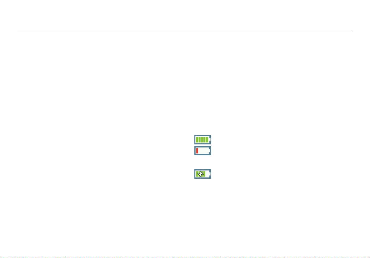
The battery icon in the upper-right corner of the screen
visually displays the amount of charge remaining before the
internal battery is completely drained:
The battery is fully or almost fully charged.
The battery life is low. Connect the ac adapter
to the charging port to charge the battery and
ensure the Tester continues to operate.
The ac adapter is connected to the charging
port.
NOTE: The battery will not charge if the internal temperature
of the Tester is above 122ºF (50ºC).
5
Page 19
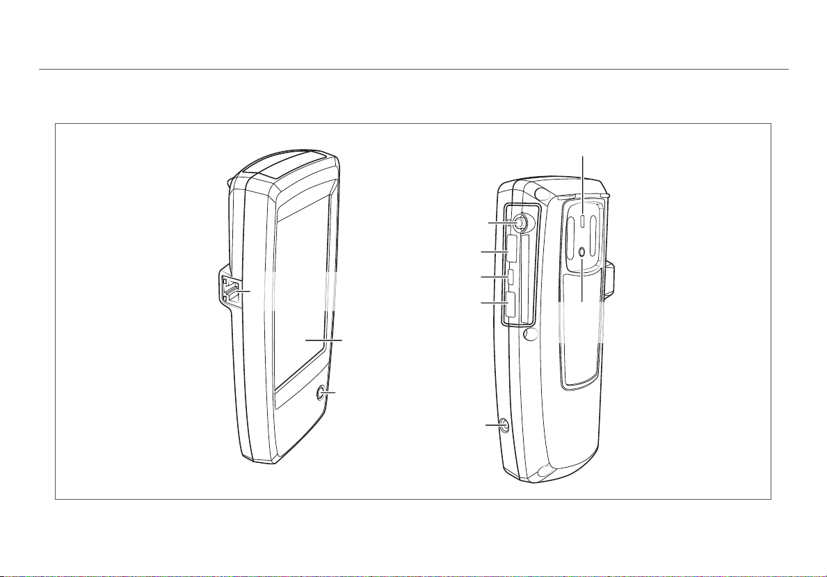
2. AIRCHECK G2 TESTER PHYSICAL FEATURES
Touchscreen
Power Button
and LED
RJ-45 Ethernet
Port
10/100/1000 Mbps
External
Antenna
Connector
USB Port 1
Micro USB Port 2
USB Port 3
Charging
Port
Kensington
Lock
External
Antenna
Holder
Power Button: Turns
the Tester unit on or off.
When the Tester is off,
press this button to
power on.
When the Tester is on,
press for one second
to shut it down.
For “hard” power off,
without software
shutdown, press for
four seconds.
The Power LED glows
green when the unit is
on and glows red when
the battery is charging
but the unit is off.
Once the battery is fully
charged, the LED turns
off.
Charging Port:
Connects with the AC
adapter to charge the
unit’s internal battery.
External Antenna:
Sold separately.
USB Port 1: For
500mA of current (any
supported USB
peripheral)
Micro USB Port 2: For
communication with
AirCheck G2 Manager
over a USB Micro-toType-B cable
USB Port 3: For
200mA of current, e.g.,
thumb drives, etc.
AirCheck G2 Tester Physical Features
Figure 1. AirCheck G2 Physical Features
6
Page 20
3. THE AIRCHECK G2 HOME SCREEN
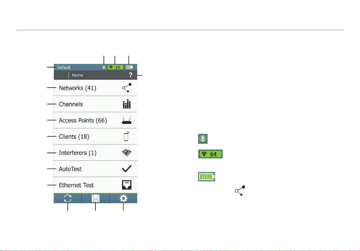
Figure 2. AirCheck G2 Home Screen
The AirCheck G2 Home Screen
The AirCheck G2 Wireless Tester features a full color
touchscreen. Touch functions are noted in the following
descriptions of the Home Screen components:
Profile Name: This field displays the name of the Profile
the Tester is currently using. The Profile is Default if you
have not created a custom Profile. The name shows an
asterisk (*) if you have changed a Profile-related setting
on the Tester since you loaded or saved the Profile.
NOTE: Touch the profile name to open the Profiles
screen, where you can save, manage, load, and upload
your profiles to Link-Live. See “Using Profiles to Manage
Settings and Security Credentials,” page 50.
This Transmitting Indicator appears when the
Tester is actively transmitting packet data.
The Channel Indicator Shows the Wi-Fi
el that AirCheck G2 is scanning in real
chann
time.
The Battery Life Indicator visually displays the
amount of charge remaining.
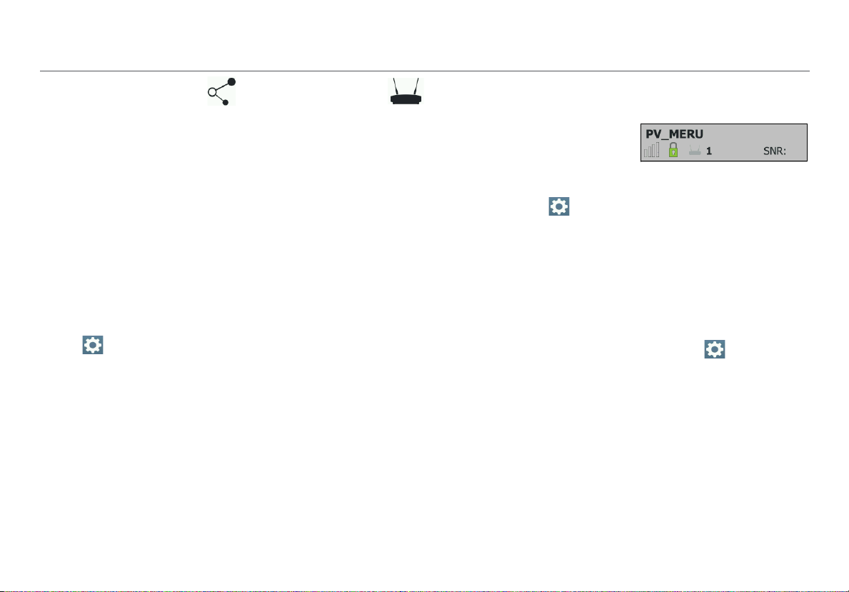
Networks (#) : This function discovers wireless LANs
and displays the number of networks discovered in
parentheses. Touch this row to view the discovered
Networks list screen. See “Discovering Networks and
Access Points,” page 9.
7
Page 21
The AirCheck G2 Home Screen
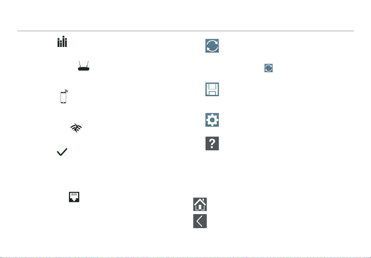
Channels : This function illustrates usage of WLAN
channels. Touch to view the Channel Utilization screen.
See “Viewing Channel Usage,” page 21.
Access Points (#) : This function discovers access
points and displays the number discover
view the discovered Access Points list. See “Discovering
Networks and Access Points,” page 9.
ed. Touch to
Clients (#) : This function discovers associated and
un-associated (e.g., probing) clients and displays the
number discovered. Touch to view the discovered
Clients li
st. See “Discovering Clients,” page 27.
Interferers (#) : This function discovers potential
interfering devices. Touch to view the Interferer Eve
list screen. See “Detecting Interferers,” page 32.
nts
AutoTest : This function automatically checks the
health of your network by measuring air quality (channel
usage and interference) and configured networks. Touch
to begin AutoTest and open the AutoTest screen. See
“Using AutoTest to Diagnose Your Network
page 36.
Health,”
Ethernet Test : This function runs a wired network
test across 10/100/1000 Mbps links and verifies Power
over Ethernet (PoE). Touch
test and open the Ethernet Test screen. See “Testing
Ethernet for Access Point Backhaul,” page 45.
this row to begin an Ethernet
Refresh: Touch this icon to clear the current
results and restart the discovery process.
Caution
Touching the Refresh button will
erase all unsaved results.
Save: Touch this icon to save your current
discovery and test results to a session file. See
“Saving Session Files and Packet Captures,”
page 86.
Settings: Touch this icon to manage your Tester’s
settings and files. See “All AirCheck G2 Settings,”
page 98.
Help: Touch this icon to open the relevant Help
topic for the screen.
To save a screen capture, hold your finger on the
icon for one second to save an image of the
current screen to internal storage on the Tester.
The Tester beeps once when a screenshot is
saved. See “Saving Screenshot Image Files,”
page 91.
Touch the Ho
from any other screen on the AirCheck G2 Tester.
Touch the Back button to return to the previous
screen from any screen except the Home Screen.
me button to return to the Home Screen
8
Page 22
4. DISCOVERING NETWORKS AND ACCESS POINTS
Discovering Networks and Access Points
The Networks list and the Access Points list are populated
with SSIDs and access points that have been discovered by
the AirCheck G2 Tester in your location.
1
From the Home Screen, select Networks or Access
Points. The Tester shows the Networks list (Figure 3) or
Access Points li
2
To see details about a network or access point, touch its
row in the list to open the Network or AP Details screen.
NOTES:
By default, the Tester hears wireless signals on both the
2.4-GHz (b/g/n/ax) and 5-GHz (a/n/ac/ax) frequency
bands. To change thi
Settings > 802.11 Settings > Bands.
to
The Netwo
update with each scanning cycle.
An SSID is in bl
in range.
st (Figure 7).
s setting, from the Home Screen, go
rks and Access Points screens automatically
ack text if the network (or access point) is
By default, a device row’s
ackground turns gray to
b
indicate that a network or
device has not been detected for the last four scans, or is
now out of range
Screen, go to Settings > 802.11 Settings > Inaudible
Devices.
If a network name is shown as [H
does not broadcast its SSID.
If an SSID shows in square brackets, the Tester found the
en SSID in packets from other wireless clients.
hidd
Colored bars that indicate the status or rating of Signal
ength and Level, Noise, and SNR are controlled by
Str
Thresholds, which can be configured in
See “Adjusting the Test Thresholds,” page 56.
. To change this setting, from the Home
idden], the network
Settings.
9
Page 23
Discovering Networks and Access Points
The Networks List Screen
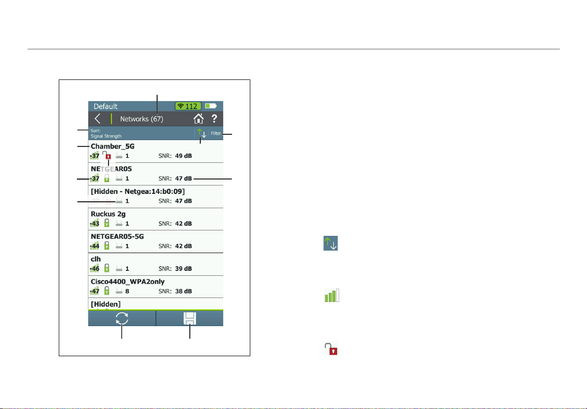
Figure 3. Networks List Screen
The Netw
networks that the AirCheck G2 has discovered in your
environment. The networks are identified by SSID.
orks list screen provides an overview of the Wi-Fi
Networks (#): The screen title displays the number of
networks discovered by the Tester.
Sort (Option Field): This field shows the sort option that
is currently applied. In Figure 3, the sort option applied is
Signal Strength.
Touch the So
networks are listed. The value by which the list is sorted
shows prominently for each network. For example, if you
change to Sort by Client Count, the Networks list screen
displays the number of connected Clients on each
network (See Figure 5), instead of the SNR, as shown in
Figure 3.
This is the default.
rt: field to change the order in which
Sort Order Button: These arrows switch the list
order from ascending to descending, and vice versa.
SSID: Service Set Identifier; The name of the wireless
network.
Signal Strength Bar Graph: The signal strength in
dBm of the AP with the strongest signal strength
connected to the network.
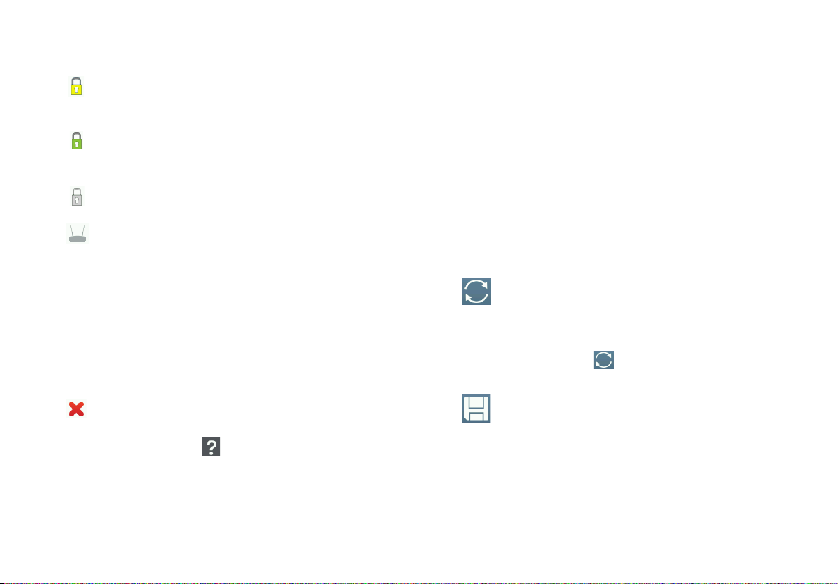
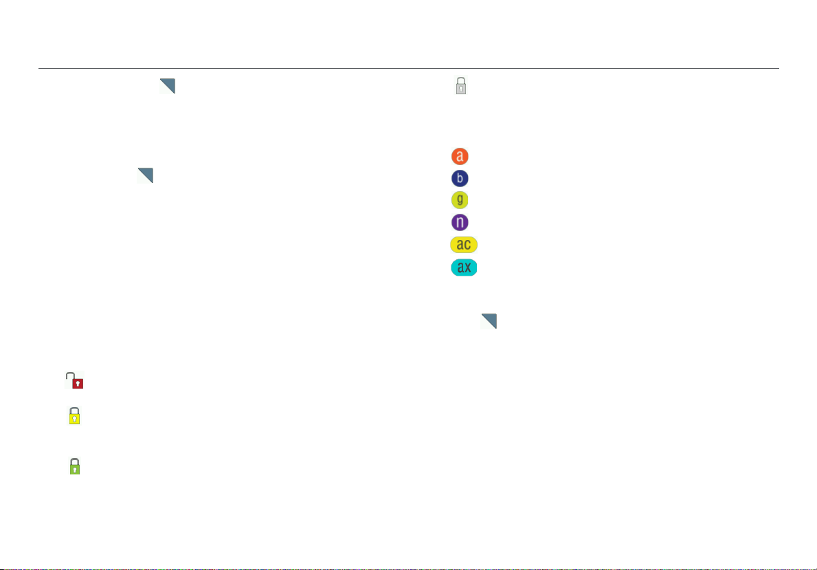
Security status of the network:
Red open lock: The network does not have security
enabled.
10
Page 24
Discovering Networks and Access Points
Yellow closed lock: One or more access points use
WEP or Cisco LEAP security protocol. These are less
secure than other protocols.
Green closed lock: All access points use security
protocols that are more secure than WEP, for example,
WPA or WPA2.
Gray closed lock: Access points on this network are
using multiple security protocols.
Access Points #: The number displayed next to the
icon is the number of access points near
your location.
Filter Button: Touch this field to add a filter for specific
network characteristics, such as SSID string, minimum
signal strength, or 802.11 media type.
NOTE: You can
set, the Networks list screen re-opens. The title of the
screen changes to “Networks (X of Y)”, such that
X = the number of networks filtered, and
Y = the total number of networks discovered.
This icon appears to the right of the active filter.
Touch the icon to remove the filter.
Touch the Help button on the Filter Networks By:
screen for more detail about each option.
set only one filter at a time. Once a filter is
SNR: Signal-to-Noise Ratio, a measure of signal strength
relative to noise. The ratio is measured in decibels (dB).
NOTE: For networks, the SNR of the strongest AP in the
network is displayed.
This is also a variable field, which changes based on the
Sort option currently applied. For example, if the list is
sorted by Client Count, the number of clients connected
to the network will appear in this space on the screen (as
shown in Figure 5).
For Networks, this space can also show the 802.11 Type,
Band, or time since the network was Last Seen.
Refresh: Touch this icon to clear the current
results and restart the current discovery
process.
Caution
Touching the Refresh button will
erase all unsaved test results.
Save: Touch this button to save a session file
containing the discovery and test results that
have been collected since the AirCheck G2
last refreshed. See “Saving Session Files and
Packet Captures,” page 86.
11
Page 25
Discovering Networks and Access Points
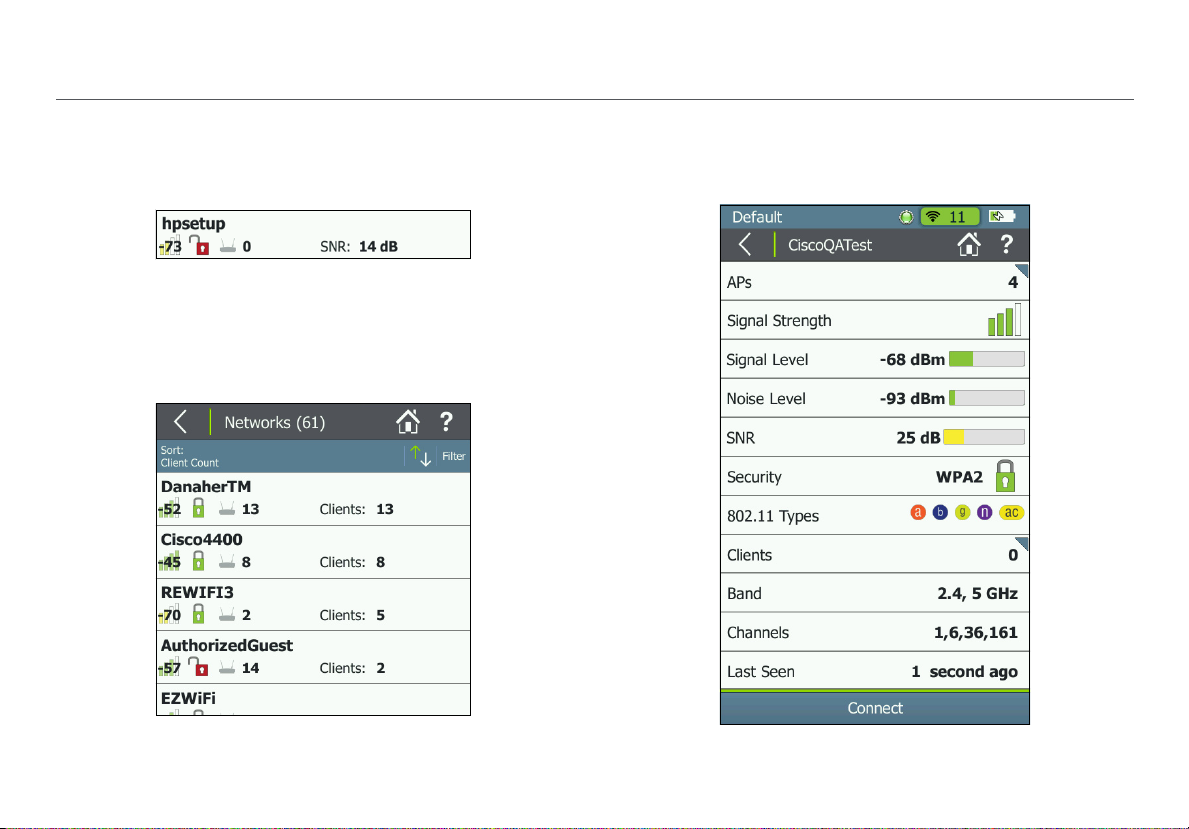
How to: Search for Ad-Hoc networks
On the Networks list screen, look for networks with 0 APs
and 1 or more clients. These could be Ad-Hoc Networks.
Figure 4. Possible Ad-Hoc Network
For help searching, Sort the Networks list by Client Count to
be able to see the number of connected clients for each
discovered network on the list screen. Figure 5 shows the
Networks list sorted by Client Count:
The Network Details Screen
Touch any network’s row on the Networks list screen (Figure
3) to open the Network Details screen.
Figure 5. Networks Sorted by Client Count
Figure 6. Network Details Screen
12
Page 26
Discovering Networks and Access Points
This triangle symbol in the top right corner of a field
indicates that you can touch the field to go to a new screen.
Touch functions are explained in the following descriptions:
Screen Title: The SSID of the network shown.
APs: The number of access points detected on this network
at your location. Touch this row to open the Access
Points list screen with the APs filtered for the selected
network.
Signal Strength: The signal strength of the strongest AP on
the network.
Signal Level: The signal level in dBm from the strongest AP.
Noise Level: The noise level in dBm from the environment.
SNR: Signal-to-Noise Ratio is a measure of signal strength
relative to noise; an indication of signal quality for a reliable
client’s connection. The ratio is measured in decibels (dB).
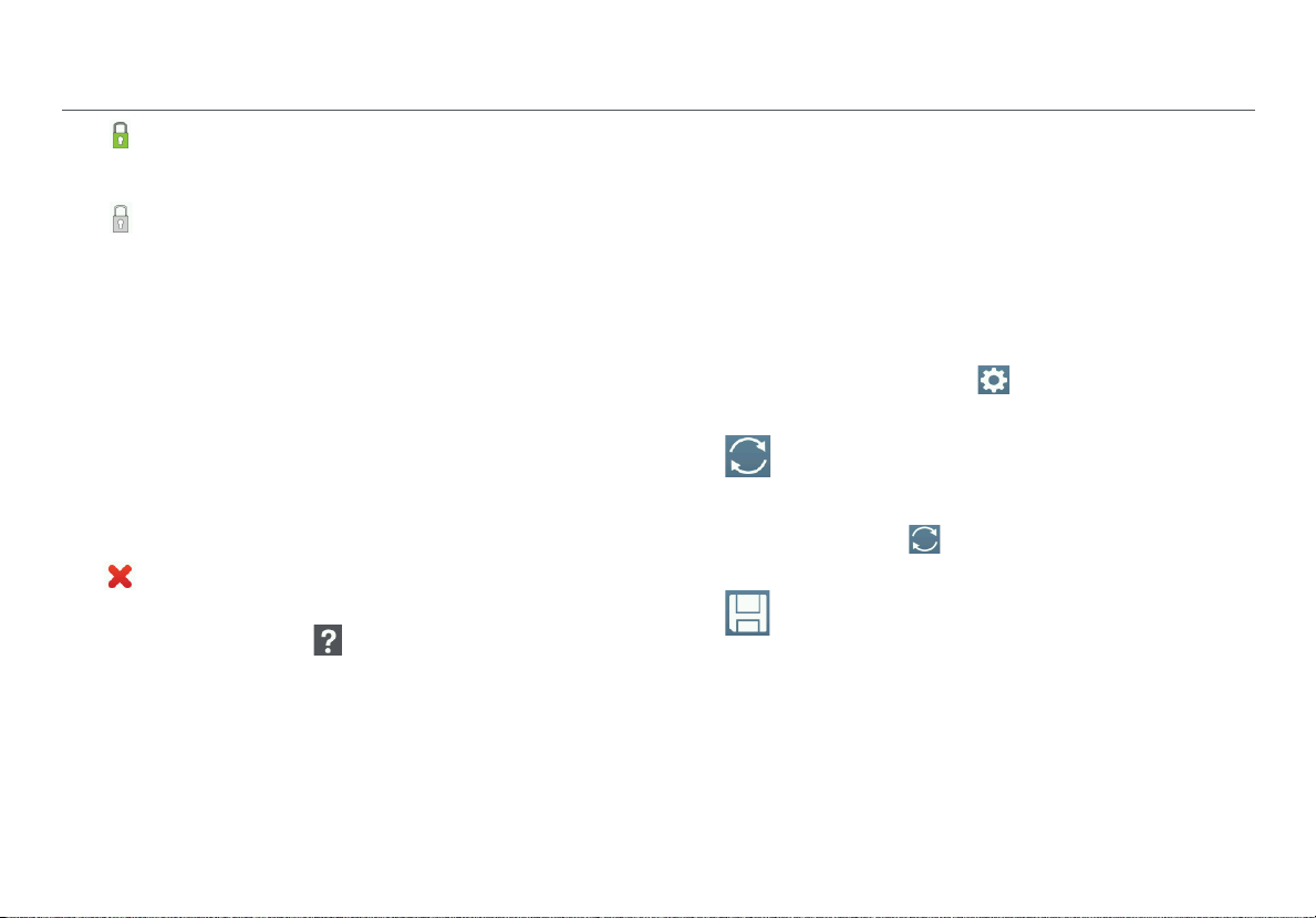
Security status of the network:
Red open lock: The network does not have security
enabled.
Yellow closed lock: One or more access points use
WEP or Cisco LEAP security protocol. These are less
secure than other protocols.
Green closed lock: All access points use security
protocols that are more secure than WEP, for example,
WPA or WPA2.
Gray closed lock: Access points on this network are
using multiple security protocols.
802.11 Types: The 802.11 standards that the access points in
the network use:
802.11a: Uses the 5-GHz band.
802.11b: Uses the 2.4-GHz band.
802.11g: Uses the 2.4-GHz band.
802.11n: Can be used in the 2.4 GHz or 5 GHz bands.
802.11ac: Uses the 5-GHz band.
802.11ax: Can be used in the 2.4 GHz or 5 GHz
bands.
Clients: The number of Wi-Fi clients discovered on the
network. Touch this row to open the Clients screen,
which shows all clients filtered for the selected network.
Band: The radio band used by the network: 2.4 GHz, 5 GHz,
or both.
Channels: The Wi-Fi channels used by the network.
NOTES:
For 20-MHz channels, the Tester displays the channel
number.
For 40-, 80-, and 160-MHz channels, it displays the
primary channel number.
13
Page 27

Discovering Networks and Access Points
For multiple channels, it displays all channel numbers
if space permits; otherwise, it truncates to what fits,
followed by "...".
Last Seen: The time since the last packet was detected from
the selected network.
Connect: Touch this button to connect to the Wi-Fi network
and run a Connection test. See “Running a Connect to
Network or Connect to AP Test,” page 60.
The Access Points List Screen
Touch Access Points on the Home Screen to open the list of
discovered APs.
NOTE: If Group Virtual APs is enabled in the Tester’s
Settings, virtual APs are grouped by BSSID, and the
Access Points list shows individual physical APs.
If the AP grouping setting is Off, each virtual access point
is shown as a single access point.
The Tester displays an access point that supports both
bands as two separate access points, regardless of AP
grouping settings.
See “802.11 Settings,” page 102.
14
Page 28
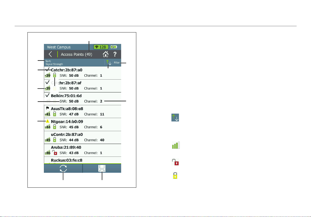
Figure 7. Access Points List
Discovering Networks and Access Points
The Access Points list screen displays all the access points
that AirCheck G2 has discovered.
Access Points (#): The number of APs discovered by the
Tester.
Sort (Option Field): This field shows the sort option that
is currently applied. In Figure 7, the sort option applied is
Signal Strength.
Touch the So
points are listed. The value by which the list is sorted
shows prominently for each access point. For example, if
you change to Sort by Client Count, the Access Points
list screen displays the number of connected clients for
each AP, instead of the Channel, as shown in Figure 7.
This is the default.
rt field to change the order in which access
Sort Order Button: These arrows switch the list
order from ascending to descending, and vice versa.
BSSID: Basic Service Set Identifier; The MAC address of
the access point.
Signal Strength: The AP’s signal strength in dBm.
Security status of the AP:
Red open lock: The network does not have security
enabled.
Yellow closed lock: O
WEP or Cisco LEAP security protocol. These are less
secure than other protocols.
ne or more access points use
15
Page 29
Discovering Networks and Access Points
Green closed lock: All access points use security
protocols that are more secure than WEP, for example,
WPA or WPA2.
Gray closed lock: Access points on this network are
using multiple security protocols.
SNR: The AP’s Signal-to-Noise Ratio, a measure of signal
strength relative to noise. The ratio is measured in
decibels (dB).
Filter Button: Touch here to filter for specific AP
characteristics, such as minimum signal strength, 802.11
type, or channel.
NOTE: You can
set, the Access Points screen re-opens. The title of the
screen changes to “Access Points (X of Y)”, such that
X = the number of access points filtered, and
Y = the total number of access points discovered.
This icon appears to the right of the active filter.
Touch the icon to remove the filter.
Touch the Help button on the Filter Access Points By:
screen for more detail about each option.
set only one filter at a time. Once a filter is
Channel: The channel used by the AP.
This is also a v
Sort option currently applied. For example, if the list is
sorted by Client Count, the number of clients connected
ariable field, which changes based on the
to the access point will appear in this space on the
screen.
For Access Points, this space can also show the SSID,
BSSID, Band, or time since the network was Last Seen.
Authorization Class Icon: If the AP has a user-assigned
authorization class saved to the current profile, an
authorization indicator appears to the left of the AP
name. Authorization Class can be assigned to individual
APs from the AP Details screen, and the default
Authorization can be set in
Settings.
Refresh: Touch this icon to clear the current
results and restart the discovery process.
Settings > 802.11
Caution
Touching the Refresh button will erase
all unsaved test results.
Save: Touch this button to save a session file
containing the discovery and test results that
have been collected since the AirCheck G2
last refreshed. See “Saving Session Files and
Packet Captures,” page 86.
16
Page 30
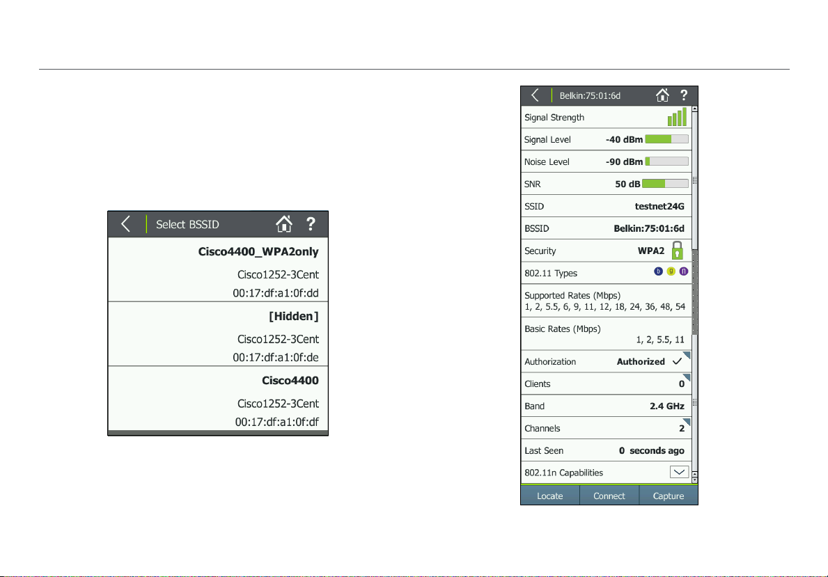
The Access Point Details Screen
Touch an Access Point’s row on the Access Points list screen
to open the Details screen for that AP.
When Group Virtual APs is turned On, multiple SSIDs from
the same AP radio are shown and counted as one AP. If you
touch one of these access points to open its Details, the
Tester displays a list of BSSIDs for you to choose from.
Figure 8. Select BSSID to View AP Details
Discovering Networks and Access Points
17
Figure 9. Access Point Details Screen
Page 31

Discovering Networks and Access Points
Screen Title: The AP’s name (BSSID, Cisco AP name, or usercreated alias) is displayed at the top of the AP Details screen.
Signal Strength: The signal strength rating for the AP.
Signal Level: The AP’s signal level in dBm.
NOTE: If Custom Signal Adjustments are applied to a
client, an asterisk (*) appears next to the Signal Level
value on this screen. To access this setting, go to
Settings > 802.11 Settings > Custom Signal
Adjustments.
Noise Level: The noise level in dBm of the channel used.
SNR: Signal-to-Noise Ratio is a measure of signal strength
relative to noise; an indication of signal quality for a reliable
client’s connection. The ratio is measured in decibels (dB).
SSID: Service Set Identifier; The name of the wireless network
to which the AP is connected.
BSSID: The MAC address of the SSID. The address starts with
a vendor abbreviation prefix, if the prefix is available.
Security status of the AP:
Red open lock: The network does not have security
enabled.
Yellow closed lock: One or more access points use
WEP or Cisco LEAP security protocol. These are less
secure than other protocols.
Green closed lock: All access points use security
protocols that are more secure than WEP, for example,
WPA or WPA2.
Gray closed lock: Access points on this network are
using multiple security protocols.
802.11 Types: The 802.11 types that the access point
supports:
802.11a: Uses the 5-GHz band.
802.11b: Uses the 2.4-GHz band.
802.11g: Uses the 2.4-GHz band.
802.11n: Can be used in the 2.4 GHz or 5 GHz bands.
802.11ac: Uses the 5-GHz band.
802.11ax: Can be used in the 2.4 GHz or 5 GHz
bands.
Supported Rates (Mbps): The extended physical (PHY) rates
that the AP is configured to support.
Basic Rates (Mbps): The basic physical (PHY) rates that the
AP is configured to support.
Authorization: Either the AP's manually selected
Authorization Class or the default Authorization Class. The
default authorization can be None, Authorized, or
Unknown. Touch this field to configure the Alias Name and
Authorization Class for the selected AP.
18
Page 32

Discovering Networks and Access Points
User-assignable Authorization Classes include the
following:
Default - Selecting Default will set the Authorization
Class to the default configuration. If you have not set a
default authorization, the default for unassigned is
None. The default AP Authorization Class can be
changed on the AirCheck G2 in Settings > 802.11
Settings > Default AP Authorization or using AirCheck
G2 Manager's Profile Setup.
Authorized
- For APs that are approved for use on
your network.
Flagged
- To give visibility to a specific AP, such as a
temporary or guest AP.
Neighbor
- For APs that are owned and controlled
by neighboring organizations.
Unauthorized
- For APs that are not supposed to
be on the network and may present a security risk.
Unknown
- For APs that have not yet been
identified or otherwise classified.
If the AP supports more than one BSSID, the
NOTE:
majority of the BSSIDs must be marked with the same
user-assigned Authorization status before the symbol
will appear on the Access Points screen.
Clients: The number of clients connected to the AP.
Touch this row to open the Clients list screen with the
clients filtered for the selected AP.
Band: The radio band the AP supports.
Channels: The channels that the access point is using.
Touch this row to open the Channels Utilization screen
for the primary channel.
Last Seen: The amount of time that has passed since the
Tester last detected the AP.
802.11n Capabilities: Select the down arrow to expand
for the AP's 802.11n capabilities.
NOTE: The "802.11n Capabilities” are taken from HT
Capabilities in the beacon and included for 802.11n and
802.11ac APs. This field is available only for 802.11n and
802.11ac APs.
802.11ac Capabilities: Select the down arrow to expand
for the AP's 802.11ac capabilities.
NOTE: The “802.11ac Capabilities” are taken from VHT
Capabilities in the beacon and included for 802.11ac APs.
This field is available only for 802.11ac APs. Because an
802.11ac-only AP reports in its beacon both the HT
Capability and VHT Capability elements, an 802.11ac-only
AP will include both the 802.11ac and the 802.11n
Capabilities fields.
19
Page 33

Discovering Networks and Access Points
802.11ax Capabilities: Select the down arrow to expand
for the AP's 802.11ax capabilities.
NOTE: The “802.11ax Capabilities” are taken from HE
Capabilities in the beacon and included for 11ax APs.
This field is available only for 802.11ax APs.
Locate: Touch this button to open the Locate screen and
physically locate an access point. See “Locating an Access
Point, Client, or Interferer,” page 66.
Connect: Touch this button to connect to the access point
and run a Connection test. See “Running a Connect to
Network or Connect to AP Test,” page 60.
Capture: Touch this button to open the Capture screen and
start a packet capture on the selected AP. See “Creating a
Standalone Packet Capture,” page 88.
Troubleshoot: If the Tester Does Not Discover an Access Point or Network
If the Tester cannot hear an access point, consider the
following possible causes:
The Tester cannot hear the access point because you
too far away.
The access point does not beacon when the Tester is
listening to the channel t
The Tester cannot hear the access point because the
signal cannot
There is too much interference on the channel that the
access point uses.
Screen to view the interference from non-802.11 sources
on the channel.
A filter is active on the current screen that is filtering out
one or more APs. Touch
Other configuration settings do not match the AP
racteristics (band, channel, etc.).
cha
The Interferers Only Scan setting is enabled in
Settings > Interferer Settings.
go through a wall or some other barrier.
hat the access point uses.
Select Channels from the Home
to clear the filter.
are
20
Page 34

5. VIEWING CHANNEL USAGE
Figure 10. Channels Utilization Screen
Viewing Channel Usage
The Channels Utilization Screen
From the Home Screen, touch Channels to open the
Channels Utilization screen, which provides an overview of
all channels and their APs.
AirCheck G2 calculates and records the average 802.11 and
Non 802.11 channel utilization for each channel per each
scan. Discrete channel utilization measurements begin when
you power on and update with each scan.
Bands: By default, the Tester scans channels on the
2.4 GHz and 5 GHz bands. To change the bands for this
function, go to
Settings > 802.11 Settings > Bands.
Channel Number: The channel corresponding with the
bar graph above it.
Bar Graphs and Dots: The bar graphs show how
much of the channel capacity is used by 802.11
devices (blue) and by non-802.11 interference
(gray). The taller the bar, the noisier the channel.
The dark blue dots in the bar graphs show how
many access points are using the channel as the
primary channel. The numeric value above the
dots also indicates the number of APs discovered
on that channel. In the example to the left,
Channel 11 has six APs.
21
Page 35

Viewing Channel Usage
NOTES:
If the Combine Utiliz
Settings > 802.11 Settings, this screen does not
separate 802.11 and non-802.11 Utilization and
shows only a combined total Utilization.
Channels that do not have access points can still
show 802.11 usage because of
points on adjacent channels.
If there are too many APs to show i
blue dots, the dots will be truncated to leave space
for the correct number of APs to display above.
ation setting is enabled in
overlap from access
ndividual dark
Illegal Channel Number: Invalid channels are
highlighted in red, according to the country selected in
Settings > Location Settings.
Overlap: Touch this button to open the Channels
Overlap screen, which displays a graphical
representation of channel width and overlap. See “The
Channels Overlap Screen,” page 25.
Refresh: Touch t
results and restart channel scanning.
his icon to clear the current
Caution
Touching the Refresh button will erase all
unsaved tes
t results.
When you save a session, AirCheck G2 records the average
and the last channel utilizations (i.e., the total utilization,
802.11 utilization, and non-802.11 utilization) for each
channel in the session. These results are sent to AirCheck G2
Manager or Link-Live when you upload the session file.
Touch a channel’s column to zoom in on that channel in the
Select Channel screen.
Save: Touch this button to save a session file
containing the discovery and test results that have
been collected since the AirCheck G2 last
refreshed. See “Saving Session Files and Packet
Captures,” page 86.
22
Page 36

Viewing Channel Usage
The Select Channel Screen
The Select Channel screen offers a close-up view of the
selected channel.
Figure 11. Select Channel Screen
The channel being selected.
The number of APs on the channel.
The bar graphs show how much of the channel capacity
is used by 802.11 devices (blue) and by non-802.11
interference (gray). The graphs update dynamically.
NOTE: If
separate 802.11 and non-802.11 Utilization and shows
only a combined total Utilization.
the Combine Utilization setting is enabled in
Settings > 802.11 Settings, this screen does not
The next lower and upper adjacent channels (faded).
The left and right arrows for scrolling the lower or higher
channels.
NOTE: When you are on the Select Channel screen, AirCheck
G2 stops scanning channels and remains only on the channel
that is selected.
Touch the middle channel bar or View Details to open the
Channel Details screen for the selected channel.
23
Page 37

Viewing Channel Usage
The Channel Details Screen
Figure 12. Channel Details Screen
The Channel Details
information about the selected channel:
Screen Title: The channel number and frequency of the
channel being monitored.
APs: The number of access points discovered on the channel.
Touch this row to open the Access Points list screen with
the APs filtered for the selected Channel.
NOTE: This field shows the number of physical access
points if Group virtual access points is selected.
Otherwise, individual BSSIDs are shown. See “802.11
Settings,” page 102.
Clients: The number of Wi-Fi clients discovered on the
channel. Touch this row to open the Clients list screen
with the clients filtered for the selected Channel.
Interferers: The number of potential Interfering devices
discovered on the channel. Touch this row to open the
Interferers list screen with the interferers filtered for the
selected Channel.
Channel Utilization (line graph): Shows 802.11 (blue) vs.
non-802.11 (gray) utilization of the channel over time. The
two horizontal bars below the line graph show in real time
the percentage of 802.11 utilization vs. non-802.11 utilization
of the channel. Very busy channels can make the network
slow or affect connectivity.
NOTE: If the Combine Utilization setting is enabled in
Settings > 802.11 Settings, this screen does not
screen shows the following detailed
24
Page 38

Viewing Channel Usage
separate 802.11 and non-802.11 Utilization and shows
only a combined total Utilization.
Figure 13. Combined Channel Utilization
Signal Level: T
strongest AP signal on the channel.
Noise: The measured real-time noise level.
SNR: The measured real-time signal-to-noise ratio.
Refresh: Touch this icon to clear the current results and
restart channel scanning.
Capture: Touch this button to open the Capture screen and
start a packet capture on the selected channel. See “Creating
a Standalone Packet Capture,” page 88.
he real-time signal level (in dBm) of the
The Channels Overlap Screen
The Channels Overlap screen displays a graphical
representation of the discovered APs' utilization of each
channel. This screen displays in landscape view. Channel
numbers are on the x-axis, and the signal level in dBm is
displayed on the y-axis of the graph.
Touch the tab buttons across the top of the graph to display
the different bands and corresponding channels:
2.4 GHz — Channels 1-14
5 GHz UNII-1/2 —
38, 42, or 46)
5 GHz UNII-2 Ext — Channels
5 GHz UNII-3 — C
A colored parabola is shown on the graph for each active
s Point the AirCheck G2 detects.
Acces
Touch an AP's parabola, and then its popped-up name, to
open the corresponding AP Details screen.
Channels 36-64 (not including 34,
100-144
hannels 149-165
25
Page 39

Figure 14. Channels Overlap Screen
The parabolas are displayed using the following
cteristics:
chara
The width of the parabola represents the width of the
channel: 20
, 40, 80, or 160 MHz.
The vertical height of the parabola represents the
current signal level (in dBm)
of the AP, correlating with
the y-axis.
Viewing Channel Usage
A line extends from the top of the parabola to the AP's
primar
y channel on the x-axis.
Only APs with a detected signal level of -85 dBm or
above are shown on the graph.
Touch Utiliz
ation to return to the Channels Utilization screen.
The parabola is centered on the center channel (x-
axi
s) being used by the AP.
26
Page 40

6. DISCOVERING CLIENTS
While the Tester is on, it monitors each channel for client
traffic to discover client devices. To see these clients, touch
the Clients row on the Home Screen.
NOTES: The Tester is only able to update the client’s
information when the client transmits data at the same time
that the Tester is monitoring the channel that the client uses.
To collect client information more quickly, go to Settings
> 802.11 Settings, and enable only one band, which
decreases the number of monitored channels.
The Client List Screen
The Clients list screen provides an overview of the Wi-Fi
clients discovered in your environment. It shows the
following information for each of the clients:
Clients (#): The numeric value in parentheses indicates
the number of active clients discovered.
Sort (Option Field): This field shows the sort option that
is currently applied. In Figure 15, the sort option applied
is MAC Ad
dress.
Discovering Clients
Figure 15. Clients List Screen
27
Page 41

Discovering Clients
Touch the Sort field to change the order in which clients
are listed. The value by which the list is sorted shows
prominently for each client. For example, if you change
to Sort by 802.11 Type, the Clients list screen displays
the 802.11 type icons next to each client, instead of the
AP it is connected to, as shown in Figure 15.
Sort Order Button: These arrows switch the list
order from ascending to descending, and vice versa.
MAC: The MAC address of the client. The address starts
with a vendor abbreviation prefix, if the prefix is
available.
The client name can be either (1) MAC colon
NOTE:
format, e.g., 00:11:22:33:44:55 or (2) OUI compact colon
format, i.e., Vendor:33:44:55. You can set or change the
client display format from Settings > 802.11 Settings
> MAC Address Format.
(Signal Strength): The client’s signal strength. The
color of the bars and the numeric value change with the
actual fluctuation of signal strength.
Security status of the AP:
Red open lock: The network d
enabled.
Yellow closed lock: One or more access points use
WEP or Cisco LEAP security protocol. These are less
secure than other protocols.
oes not have security
Green closed lock: All access points use security
protocols that are more secure than WEP, for example,
WPA or WPA2.
Refresh: Touch this icon to clear the current
results and restart the scan.
Caution
Touching the Refresh button will erase all
unsaved test results.
Save: Touch this button to save a session file
containing the discovery and test results that have
been collected since the AirCheck G2 last
refreshed. See “Saving Session Files and Packet
Captures,” page 86.
Filter Button: Touch here to filter for specific client
characteristics, such as AP name, security type, or time
since the client was last seen.
NOTE: You can set onl
set, the Clients screen re-opens. The title of the screen
changes to “Clients (X of Y)”, such that
X = the number of clients filtered, and
Y = the total number of clients discovered.
This icon appears to the right of the active filter.
Touch the icon to remove the filter.
Touch the Help button on the Filter Clients By:
screen for more detail about each option.
28
y one filter at a time. Once a filter is
Page 42

Discovering Clients
Channel: The channel a client is using. This field is blank
for probing clients.
AP: Shows the name of the AP the client is associated
with. This field is blank for probing clients.
This is also a variable field, which changes based on the
Sort option currently applied. For example, if the list is
sorted by 802.11 Type, the 802.11 type icons will appear
in this space on the screen, instead of the AP name.
For Clients, this space can also show the SSID, AP BSSID,
Band, or time since the network was Last Seen.
To open the Details screen for a client, touch its row.
The Client Details Screen
The Client Details screen shows the following detailed
information about the client you have selected:
Screen Title: The client’s full MAC address (e.g.,
00:11:22:33:44:55) or OUI compact colon format (e.g.,
Vendor:05:3f:76). See “802.11 Settings,” page 102.
Signal Strength: The client's signal strength in four bars. The
color of the bars changes in real time to reflect the actual
fluctuation in the client's signal strength.
Signal Level: The client's actual signal level in dBm and a
horizontal bar indicating the rating.
SSID: The SSID with which the client is associated. The field
will be blank when no client-AP association is detected.
AP Name: The name of the AP with which the client is
associated. The field will be blank when no client-AP
association is detected.
AP BSSID: The BSSID of the AP with which the client is
associated. The field will be blank when no client-AP
association is detected.
Connection Rate: The speed in Mbps of the last frame seen
from the client.
29
Page 43

Discovering Clients
Security: Shows the
security type for the client-AP
connection. The field will be blank if the client is not
associated with an AP, is using an ad-hoc connection, or its
security standard is unknown.
802.11 Type: The 802.11 type that the client is using:
802.11a: Uses the 5-GHz band.
802.11b: Uses the 2.4-GHz band.
802.11g: Uses the 2.4-GHz band.
802.11n: Can be used in the 2.4 GHz or 5 GHz bands.
802.11ac: Uses the 5-GHz band.
802.11ax: Can be used in the 2.4 GHz or 5 GHz
bands.
Band: Shows the Wi-Fi band of the client connection.
Channel: The primary channel the client is using. Select this
field to open the Channel Details screen for more
information about this primary channel.
Last Seen: Shows the time when the last packet from the
client was detected.
Probes For: Shows the SSID from the last probe request. The
field is populated only for non-associated clients; it is blank
for associated clients.
Figure 16. Client Details Screen
30
Page 44

Discovering Clients
Locate: Touch this button to open the Locate screen and
begin locating the client. See “Locating an Access Point,
Client, or Interferer,” page 66.
Capture: Touch this button to open the Capture screen and
start a packet capture on the selected client. See “Creating a
Standalone Packet Capture,” page 88.
Troubleshoot: If the Tester Does Not Discover a Client
In some situations, the Tester will not discover a client
because of the following:
The wireless card in the client is disabled.
The Tester cannot hear the client because you are too far
from the client.
away
The Tester cannot hear the client because the signal
cannot go through a wall or some other barrier.
There is too much interference on the channel that the
client uses. Select Channe
non-802.11 sources on the channel.
The Tester does not scan the band that the client uses.
See the set
The client does not transmit when the Tester is listening
to the channel t
A Filt
one or more clients. Touch
The Interferers Only Scan setting is enabled in
Settings > Interferer Settings.
ting in Settings > 802.11 Settings.
hat the client uses.
er is active on the current screen that is filtering out
ls to see the interference from
to clear the filter.
31
Page 45

7. DETECTING INTERFERERS
Detecting Interferers
As the AirCheck G2 scans through your local wireless
channels, it also observes and records devices that might be
causing interference, such as a microwave oven, wireless
mouse, or Bluetooth device. Interference from non-802.11
devices can negatively impact your network performance.
When a potential interfering device is detected, AirCheck G2
populates the Interferer Events screen with data about the
interferer. To see these interferer events, touch the
Interferers row on the Home Screen.
NOTES:
To collect interferer information more quickly, go to
Settings > Interferer Settings, and enable only
one band, which decreases the number of monitored
channels.
You can also turn On th
to cause the AirCheck G2 to look ONLY for interfering
devices. AirCheck G2 will not discover or display
Networks, APs, Clients, or Channel utilization while the
Interferers Only Scan is On.
To view a list of all the interferer types AirCheck G2 can
display if detected, t
and then the Type field.
e Interferers Only Scan option
ouch the Filter button (Figure 17)
The Interferer Events List Screen
The Interferer Events screen lists the interference events that
have been detected in your environment. It shows the
following information for each of the interferers:
Interferer Events (#): The numeric value in parentheses
indicates the number of interference sources that have
been observed as active during the last 30 seconds.
Sort (Option Field): This field shows the sort option that
is currently applied. The default sort option is Event ID.
Touch the So
interferers are listed. The value by which the list is sorted
shows prominently for each interferer. For example, if
you change to Sort by Channels Impacted, the Events
list screen displays the impacted channel number range
next to each interferer, instead of the Band it is
operating on, as shown in Figure 17.
rt field to change the order in which
Sort Order Button: These arrows switch the list
order from ascending to descending, and vice versa.
Event (#): Numbers the interferer events in order of
occurrence. NOTE: Events may or may not be listed in
sequential order, based on the selected Sort option and
Inaudible Interferers settings (in Settings > Interferer
Settings).
32
Page 46

Detecting Interferers
Device Type: Shows the type of interfering device
detected by AirCheck G2.
Figure 17. Interferer Events List Screen
Power: The most recently observed power output in
dBm of the interfering device.
Util: The percentage of time, during the most recent
sample, for which the interferer was detected.
Band: The band on which the AirCheck G2 detects the
interfering device.
This is also a variable field
Sort option currently applied. For example, if the list is
sorted by Channels Impacted, the range of channels
affected by the interferer appears in this space on the
screen, instead of the Band.
For Interferer Events, this space can also show the Peak
(Power), Channels Impacted, Number of Channels
Impacted, or time since the interferer was Last Seen.
, which changes based on the
Filter Button: Touch here to filter for specific interferer
characteristics, such as device type, channels impacted,
or minimum average power.
NOTE: You can set onl
set, the Interferer Events screen re-opens. The title of
the screen changes to “Interferer Events (X of Y)”, such
that
X = the number of interferers filtered, and
Y = the total number of interferers discovered.
This icon appears to the right of the active filter.
Touch the icon to remove the filter.
y one filter at a time. Once a filter is
33
Page 47

Detecting Interferers
Locate: Touch this button to open the Select Interferer
screen and then begin locating an interferer type. See
“Locating an Access Point, Cli
66.
Refresh: Touch t
results and restart the scan.
his icon to clear the current
ent, or Interferer,” page
Caution
Touching the Refresh button will erase all
unsaved tes
To open the Details screen for an interferer event, touch its
row.
Save: Touch this button to save a session file
containing the discovery and test results that have
been collected since the AirCheck G2 last
refreshed. See “Saving Session Files and Packet
Captures,” page 86.
t results.
The Interferer Event Details Screen
The Interferer Event Details screen shows the following
detailed information about the interferer you have selected:
Event Number: The number of the event as assigned by the
AirCheck G2.
Type: The type of interfering device detected by AirCheck G2.
Average Power: The average observed power output in
dBm of the interfering device.
Peak Power: The highest observed power output in dBm of
the interfering device.
Duty Cycle: The percentage of time, during the most recent
sample, for which the interferer was detected.
Channels Impacted: The channel numbers for the channels
affected by the interferer.
Number Channels Impacted: How many channels are
impacted by the detected interferer.
34
Page 48

Detecting Interferers
Last Seen: The amount of time that has passed since the
interferer was most recently detected.
Event Count: The number of separate instances of AirCheck
G2 detecting transmission from the interferer.
Locate: Touch this button to open the Locate Interferer
screen and begin locating the selected interferer. See
“Locating an Access Point, Client, or Interferer,” page 66.
Figure 18. Interferer Event Details Screen
First Seen: The amount
of time that has passed since the
interferer was initially detected.
35
Page 49

Using AutoTest to Diagnose Your Network Health
8. USING AUTOTEST TO DIAGNOSE YOUR NETWORK HEALTH
AutoTest automatically checks the health of your network by
examining Air Quality for utilization and interference and
Network Quality for the SSIDs that have been configured for
AutoTest. See “AutoTest Settings,” page 109.
When AutoTest runs, the test result fields turn green, red, or
yellow to indicate the status or rating of the result. For
example, in Figure 19, the 802.11 Utilization test has passed,
the Non 802.11 Utilization and Co-Channel Interference has
received a warning, and Adjacent Channel Interference has
failed.
These ratings are controlled by the Thresholds configured in
the AirCheck G2’s Settings > Thresholds.
See “Adjusting the Test Thresholds,” page 56.
To run an AutoTest, touch the AutoTest field on the Home
Screen. The AutoTest results screen opens and results are
displayed as each test finishes.
Touch the down arrows
specific measurements.
Touch the Restart
test.
Touch the Sa
file.
button to clear results and start a new
ve icon to save the results as a session
next to each row to view
Touch the pencil icon
and edit the Test Co
uploaded to Link-Live and associated with your test
result.
to open the Comments screen
mment or Job Comment to be
Adding Comments
The Comments screen allows you to add or edit
comments that will be associated with your most recent
test result in Link-Live Cloud Service. These comments
are helpful for organizing and analyzing test results.
– Select Test Comment to attach a new comment to
your most recent test result in Link-Live. The Test
Comment does not persist after you begin a new test.
– Select Job Comment to add or edit the Job Comment,
which is attached to all test results and files uploaded
to Link-Live. The Job Comment persists until you
delete or edit it. You can also set the Job Comment
from Settings > Link-Live.
36
Page 50

AutoTest Air Quality
The Air Quality measurements include 802.11 Channel
Utilization, Non-802.11 Channel Utilization, Co-Channel
Interference, and Adjacent Channel Interference.
Figure 19. AutoTest Air Quality Results Screen
Using AutoTest to Diagnose Your Network Health
802.11 Utilization
The 802.11 Channel Utilization results include the top three
channels in each band (2.4 GHz and 5 GHz) with the highest
802.11 utilization. The channels are displayed with their
measured utilization percentage and rating of Pass,
Warning, or Fail, based on the Channel 802.11
Utilization threshold.
Figure 20. 802.11 Channel Utilization Results
Non-802.11 Utilization
The Non-802.11 Channel Utilization results include the top
three channels in each band (2.4 GHz and 5 GHz) with the
most non-802.11 interference, e.g., noise.
37
Page 51

The channel utilization percentage is displayed along with a
rating symbol: Pass, Warning, or Fail, based on the
Channel non-802.11 Utilization threshold.
NOTE: If the Combine Utilization setting is enabled in
Settings > 802.11 Settings, this screen does not
separate 802.11 and non-802.11 Utilization and shows
only a combined total Utilization.
Figure 21. Air Quality Combined Utilization
The channel usage will vary depending on the time of day,
based on the number of clients connected to the network,
the amount of interference from devices, such as
microwaves or video cameras, etc.
Using AutoTest to Diagnose Your Network Health
Figure 22. Air Quality Co-Channel and Adjacent Channel
Interference Results
38
Page 52

Using AutoTest to Diagnose Your Network Health
Co-Channel Interference
The Co-Channel Interference results display the top three
channels in each band (2.4 GHz and 5 GHz) with the highest
number of APs that exceed the minimum AP signal level
threshold on the same channel.
This measurement is independent of SSIDs and solely looks
the number of APs using the same channel and their signal
at
quality. It accounts for 40-MHz and 80-MHz channels in the
5-GHz band by counting an AP on its primary and each
secondary channel.
Pass, Warning, or Fail icon is also displayed for
A
each channel.
Adjacent Channel Interference
The Adjacent Channel Interference results display the top
three channels in the 2.4-GHz band in which APs may
experience Adjacent Channel Interference. For each channel
on which at least one AP is found, the Tester counts how
many APs are operating on other channels that overlap with
that channel. It accounts for 20-MHz and 40-MHz channels in
the 2.4-GHz band. The Adjacent Channel Interference
measurement does not apply to the 5-GHz band.
Pass, Warning, or Fail icon is also displayed for
A
each channel.
Once the Air Quality test completes, select the blue triangle
icon
Adjacent Channel Interference to open a list of the APs
interfering on that channel. Then, you can select the down
arrow next to each interfering AP to view its BSSID, SSID, and
Signal strength.
next to a channel under Co-Channel Interference or
Rogue Access Points Test
This feature classifies Rogue Access Points based on the userselected Authorization status of the detected APs. Rogue
Access Point tests as a whole can be included or excluded
from AutoTest by accessing the AutoTest Settings screen.
Figure 23. Rogue Access Points Test
If no rogue access points are detected, the field turns
green.
If AirCheck G2 detects APs that have a Fl
the field turns yellow.
agged status,
39
Page 53

If AirCheck G2 detects APs that have the
Unauthorized status, the field turns red.
If any Rogue Access Points are detected, you can touch the
down arrow to see the number and type of Rogue APs, touch
the blue triangle icon to view the AP names, and then,
touch another down arrow next to each AP to view its BSSID,
SSID, Signal strength, and channel.
AutoTest Network Tests
The Network Test measurements check for network
availability; the existence of interference from access points
using the same channel, which may cause network slowness;
AP use of consistent security methods for a network; and the
ability to connect and use the network (access to services,
other devices).
How to: Run Network Tests as part of AutoTest
1
To see these tests, you must enter and save the security
credentials for the network you wish to test.
See “Entering Network Security
2
You must also select the networks you want tested
during AutoTest from the AutoTest Settings screen
Settings > AutoTest Settings).
(
Credentials,” page 54.
Using AutoTest to Diagnose Your Network Health
Figure 24. AutoTest Settings Screen
3
Touch AutoTest from the Home Screen.
Once the SSID and security credentials have been entered,
AutoTest runs Network Tests for each network selected.
In the example shown in Figure 24, security for the SSID,
“Cisco4400,” has been configured and added to the Profile,
and the network is selected in AutoTest Settings.
Network Test results are reported on the AutoTest results
screen below the Air Quality test results. In Figure 25, the
Network test for “Cisco4400” has run and passed.
40
Page 54

Figure 25. AutoTest Network Tests
When you connect to a network, the Tester usually
NOTE:
connects through the access point that has the highest
Signal-to-Noise Ratio. If the network includes secure and
unsecured access points and security credentials are
available, the Tester tries to connect to the secure access
point that has the highest Signal-to-Noise Ratio. Some
networks use a controller that connects you to the access
point that has the least amount of traffic.
Using AutoTest to Diagnose Your Network Health
Network Quality Results
Figure 26. AutoTest Network Quality
Network Coverage: Indicates the
number of access points
the Tester detected that are supporting the network. This
field also displays a rating symbol based on the Network
Coverage threshold.
Co-channel Interference: Displays the number of APs that
exceed the minimum signal strength threshold with primary
or secondary channels on the same channel on which the
Tester connects to the network.
Security: Indicates whether all access points use security
protocols that are more secure than WEP, for example, WPA
or WPA2.
41
Page 55

Connection Test Results
The Connection test results indicate whether or not you can
connect to an AP for the configured network at your current
location. The Connection field turns green if the connection
was successful and red if the connect was unsuccessful.
Touch the down arrow to the right of Connection to view
high level connection diagnostics. These results also receive a
rating based on whether the individual test was successful, or
based on how measurements compare to the configured
thresholds: Pass or Success (green), Warning (yellow),
or Fail (red)
Connect to AP: Indicates whether the Tester was able to
connect to the AP.
Authenticate: Indicates whether the Tester was able to
authenticate with the AP.
Exchange packets with AP: Indicates whether the Tester
received packets back from the AP.
Using AutoTest to Diagnose Your Network Health
Figure 27. AutoTest Network Connection Test Results
% of Max TX Rate: The physical transmission rate as a
percentage of the maximum rate possible.
Retry Rate: The percentage of transmitted frames that are
retry frames.
BSSID: The MAC address of the access point.
42
Page 56

Using AutoTest to Diagnose Your Network Health
AP Name: The name of the AP to which the Tester is
connected. The address starts with a vendor abbreviation
prefix, if the prefix is available.
Channel: The channel the AP uses.
Other Connection Results: The rest of the results under
Connection provide exact values for the average, minimum,
and maximum Signal, Noise, SNR, and PHY Rate.
IP Address Result
IP Address: Indicates whether or not an IP was successfully
obtained via DHCP or if a static IP is configured.
Captive Portal Result
When the Captive Portal setting is enabled, this portion of
the test opens a web browser window that allows you to
enter the required credentials for the network.
See “Captive Portal” on page 62.
Target Test Results
The optional test targets show whether or not AirCheck G2
can ping the targets selected in Settings > Test Targets, which
can include the DHCP Server, Default Gateway, DNS servers,
and/or the user-configurable target (www.google.com is the
default).
Touch the arrows to the right of each field to expand or
collapse test details:
Figure 28. AutoTest Network Test IP and Test Targets
DHCP Server: Indicates whether or not the DHCP service
could be successfully pinged.
Default Gateway: Indicates whether or not the configured
gateway could be successfully pinged.
43
Page 57

DNS 1 and DNS 2: Indicate whether the DNS servers could be
successfully pinged.
Targets: Indicates whether or not these user-configured test
targets could be successfully reached via Ping or TCP Port
Open Test. The default target is www.google.com, but you
can add and edit tests targets from the Settings > Test
Targets. See “Defining Ping and TCP Port Open Test
Targets,” page 58.
Link-Live Upload: Indicates whether the AirCheck G2 Tester
was able to upload the AutoTest results to a Link-Live
account. See “Getting Started in Link-Live Cloud Service,”
page 47.
Using AutoTest to Diagnose Your Network Health
44
Page 58

9. TESTING ETHERNET FOR ACCESS POINT BACKHAUL
The Ethernet Test verifies key connectivity parameters for the
wired link to an access point.
To configure the Ethernet test, see “Ethernet Settings” on
page 112.
The Ethernet Test Results Screen
The results fields report high-level Pass (green) or Fail (red)
results of the test components. Select the down arrows
to the right of each field to view detailed information.
PoE: Indicates whether or not PoE capabilities are detected
on the current link, including the measured voltage in
parentheses if present. NOTE: You can disable the PoE test in
Ethernet Settings.
Link: Indicates whether or not a Layer-2 Ethernet link is
established. The field turns green if a link was successfully
established or red if no link could be established.
Port: Displays the switch name, model, MAC address, IP
address, port number, and VLAN IDs. The information is
gathered from switch port info packets (CDP, EDP, and LLDP).
NOTE: T
packet (LLDP, CDP, or EDP) on the wire after it establishes
link and uses this to populate the Port information. If it is
capable of hearing these packets from more than one
Figure 29. Ethernet Test Screen
he AirCheck G2 listens for the first switch info
Testing Ethernet for Access Point Backhaul
45
Page 59

Testing Ethernet for Access Point Backhaul
source, it will display the first one it receives, which may
not always be from its link partner.
Furthermore, when AirCheck G2 is not linked directly to a
managed switch that emits these types of packets, but is
instead linked with another switch in between, it will not
reliably receive this switch port information. Most of
these managed switches send these packets as soon as
they detect link establishment, which they cannot do in
this case. However, they may retransmit this information
periodically, which AirCheck G2 will receive and display if
it can.
NOTE: The switch name may be truncated if it exceeds
the length of the field.
DHCP: Indicates whether or not a DHCP address was
obtained.
Default Gateway: Indicates whether or not AirCheck G2 can
ping the default gateway.
Network: Indicates whether or not AirCheck G2 can
successfully reach a user-defined network target via Ping or
TCP Port Open test. This function can verify connectivity to a
wireless controller, for example. See “AutoTest Settings,”
page 109.
Link-Live: Indicates whether or not test results were
successfully sent to the Link-Live Cloud Service.
Stop: While the test is running, select this button to stop the
test.
Restart: After the test has completed (or you've stopped the
test), select the Restart button to start a new test.
DHCP Log: Select this button to view the test log.
Save: Touch this button to save a session file containing
the discovery and test results that have been collected since
the AirCheck G2 last refreshed. See “Saving Session Files and
Packet Captures,” page 86.
Comment: Touch this button to edit the Test Comment
or Job Comment to be uploaded to Link-Live and associated
with your test result. See “Adding Comments,” page 36.
46
Page 60

10. COMPANION SERVICES
Companion Services
These two free services enhance your testing, analysis, and
documentation capabilities with the AirCheck G2 Tester.
Introduction to Link-Live Cloud Service
This online service, once set up, automatically uploads and
saves AutoTest, Connection, and Ethernet Test results from
the AirCheck G2 any time it is connected to the internet. You
can comment on test results, label and organize your switch
and cable set up, monitor data from multiple testing devices,
and document completed jobs.
Starting with release v3.0, AirCheck G2 can also upload
profile, session, screenshot, and packet capture files to LinkLive and download software updates from Link-Live for
installation directly on the unit.
Getting Started in Link-Live Cloud Service
To start, create a user account at Link-Live.com.
Next, you must Claim the Tester to the cloud service.
How to: Claim the AirCheck G2 to Link-Live
1
After creating a user account, sign in to Link-Live Cloud
Service. The first time you sign in to Link-Live, a pop-up
dialog box appears prompting you to claim a device.
2
If you already have a user account and other devices
claimed to Link-Live, navigate to the Units page from the
left side navigation drawer by clicking the navigation
menu icon
3
Click the Claim Unit button at the lower right
corner of the screen.
4
In the Claim Unit dialog, select the AirCheck G2 image.
5
Follow the on-screen instructions to finish claiming.
6
Click “Listen” in Link-Live before you touch “Claim Unit”
on the AirCheck G2 tester.
See “Link-Live Settings,” page 100.
f you perform a factory restore on your AirCheck
NOTE: I
G2 unit, you must un-claim it on Link-Live and re-claim it
to continue uploading and viewing new test results.
Once your AirCheck G2 Tester is claimed in Link-Live, test
results will upload automatically after you have run a test
and successfully connected to the internet. The Link-Live
Upload field on the test results screens indicates whether the
test results were successfully sent to Link-Live.
.
47
Page 61

Figure 30. Successful Link-Live Upload Field
If no connection is available, the Tester will queue up to 100
entries before overwriting previous results.
You can also configure uploading and notification settings on
the Link-Live Cloud Service web site. For more information
about Link-Live, click Support > Questions from the left-side
navigation drawer on the Link-Live web page.
For instructions on uploading Profiles to Link-Live, see “How
to: Upload a Profile to Link-Live” on page 53.
For instructions on uploading Session, Screenshot, and
Capture files to Link-Live, see “How to: Upload Files to Link-
Live” on page 94.
For instructions on updating your AirCheck G2 software using
Link-Live, see “How to: Update Firmware over Link-Live” on
page 118.
Companion Services
Getting Started with the AirCheck G2 Manager PC Application
You can use the AirCheck G2 Manager computer application
for the following activities:
Upgrade the AirCheck G2 Tester’s firmware.
Update the AirCheck G2 Tester’s Vendor MAC Prefix file.
View measurement results saved as session files.
Generate reports from session files.
Set up the AirCheck G2 Tester configuration by creating
Profiles
Configure security credentials for the network(s)
containing any key d
Transfer Profiles with saved settings to the Tester.
Transfer screen capture images from the AirCheck G2
Tester to a PC.
Download the AirCheck G2 Manager software from Link-Live
at https://app.link-l
After downloading and installing the application, connect
your AirCheck G2 Wireless Tester to the PC using the supplied
Micro Type B to USB cord.
.
evices that you are pinging.
ive.com/downloads.
48
Page 62

Figure 31. Session Data > Networks in AirCheck G2
Manager
Companion Services
NOTE: Only
Micro Type B cables can be used to connect the
AirCheck G2 to a PC. USB on-the-go (OTG) cables will not
work properly.
The AirCheck G2 Manager online Help contains
more instructions for using the application.
See “Managing Profiles and Sessions on a PC using
AirCheck G2 Manager,” page 96.
49
Page 63

11. CUSTOMIZING THE TESTER FOR YOUR NETWORK
Customizing the Tester for your Network
Figure 32. Settings Menu Screen
This chapter describes how to adjust the Setti
are essential for setting up the Tester for your network and
running in-depth performance tests. For a description of all
other settings, see “All AirCheck G2 Settings” on page 98.
To change the settings on the Tester, touch the Settings
button from the Home Screen.
Help: Touch this icon to open the embedded Help topic
with a description of the current screen.
ngs that
Using Profiles to Manage Settings and Security Credentials
Profiles are files that save configuration settings for the
Tester and security credentials for networks and APs, which
let the Tester connect and perform roaming tests and
connectivity tests to DNS servers, DHCP servers, the default
router, and network targets. Profiles also include the
following information:
All 802.11 settings
AutoTest settings
Ethernet Test settings
Interferer Settings
IP addresses used for ping or TCP Port Connect tests
50
Page 64

Customizing the Tester for your Network
iPerf Settings
Location and Language
Thresholds for the colored bar graphs and Pass,
arning, and Fail ratings
W
Imported Certificates
Profiles can be password protected so that unauthorized
users cannot
use the Tester to connect to secure networks or
access network security credentials on the AirCheck G2
Manager PC application.
The AirCheck G2 Tester’s Home Screen shows the name of
the Profile the Tester is using at the top left. The name shows
an asterisk (*) if you have changed a setting on the Tester
since you last saved the Profile.
You can create and edit Profiles on both the AirCheck G2
Tester and in AirCheck G2 Manager on a personal computer
(PC).
You can also upload saved Profiles to Link-Live, and then
download them to other AirCheck G2 testers.
How to: Save the current settings as a Profile on the AirCheck G2 Tester
Multiple Profiles can be saved on the Tester, but only one
Profile at a time can be active.
1
To access the profiles screen, touch the Profile name at
the top left corner of the AirCheck G2 screen, or
from the Home Screen, touch the
Settings button
and select Profiles.
Figure 33. Settings > Profiles Menu
51
2
Touch Save or Save as.
Page 65

Customizing the Tester for your Network
To save the Profile with the current name (shown at
the top left of the screen), press Save. The Tester will
ask if you want to overwrite the existing Profile name
before saving.
To save the Profile with a new name:
a. Select Save As.
Figure 34. Profiles > Save As
b. Touch Name and use the on-screen keyboard to
type in a new name.
c. Touch DONE when finished.
To save a Se
a. Touch the down arrow to change the default Type
fro
cured Profile:
m Open to Secured.
b. Touch Password to enter a password on the on-
screen keyboard.
Caution
Ensure that you enter the password as you intend it.
Touch the open lock icon to double-check that it is
correct. If you enter the password incorrectly here, or
forget the password, you may not be able to access
your Secured Profile again.
c. Touch DONE when you finish entering the
password.
Touch A
How to: Load a Profile that is saved in the AirCheck G2 Tester
1
From the Home Screen, touch the Settings button.
2
Touch Profiles.
3
Touch Load, and select a Profile name from the list.
4
Touch Apply.
5
Enter the password if the Profile is secured.
NOTE: This icon next to a profile’s name on the Load
Profile screen indicates that the profile was downloaded
from Link-Live.
pply when you finish configuring the Profile.
52
Page 66

Customizing the Tester for your Network
How to: Transfer a Profile from a PC to the Tester
NOTE: See the AirCheck G2 Manager Help for
additional instructions.
1
Use the Profile Setup in AirCheck G2 Manager to make a
Profile.
2
Connect the Tester to the PC using the USB cable
supplied.
3
Wait for AirCheck G2 Manager to show a green
“Connected” indicator at the top left.
4
In AirCheck G2 Manager, drag and drop the Profile name
from the right panel, “Local Profiles,” to the left panel,
“AirCheck G2 Profiles” to transfer the Profile to the
Tester.
NOTE: You must Lo
you can use it.
ad the Profile on the Tester before
How to: Delete a Profile on the Tester
1
Select Settings > Profiles.
2
Touch Delete.
3
Select the checkboxes for the Profiles you want to delete.
NOTE: You cannot delete the currently active Profile.
4
Touch Apply.
5
Confirm that you want to delete by touching Yes.
How to: Upload a Profile to Link-Live
1
From the Home Screen, touch the Settings button.
2
Touch Profiles.
3
Touch Push to Link-Live, and select the checkbox for one
or more Profile names from the list.
4
Touch Apply.
5
Confirm that you want to push the profiles to Link-Live
by touching Yes.
The selected profiles are uploaded to Link-Live whenever an
active wired or Wi-Fi connection is available.
NOTE: Existing profiles with the same name are
overwritten if pushed to Link-Live or downloaded to an
AirCheck G2 unit.
Access your uploaded Profiles on Link-Live.com from the leftside navigation drawer by clicking the navigation menu icon
, and then selecting Settings > AirCheck G2 Profiles.
53
Page 67

Entering Network Security Credentials
There are three methods for entering and saving network
and AP security credentials:
From the Tester’s Ne
screen
In the Tester’s
In AirCheck G2 Manager’s Profile Setup menu
How to: Enter credentials from the Networks or Access Points list
If you select a discovered network or AP from the Networks
or Access Points list, you will not need to enter the SSID or
Authentication type.
1
From the Home Screen, touch Networks or Access
Points.
2
Touch the row of the relevant network or AP to open the
details screen.
3
From the network or AP details screen, touch the
Connect button at the bottom of the screen. See Figure
35.
twork or Access Point Details
Settings menu
Customizing the Tester for your Network
54
Figure 35. Network Details Screen
Page 68

4
If the network has not yet been configured on the
current profile, the Configure screen opens; enter the
appropriate credentials on the configuration screen.
See “Networks," page 98 for more on c
onfiguring
network settings.
5
Click the Apply button at the bottom of the screen.
The Tester will run a Connection test. Af
terwards, the
credentials for the Network or AP are retained in the unsaved
Profile, which is denoted with an asterisk (*) (shown in Figure
36).
NOTE: Notice that the Profile name at the top left of the
screen has an asterisk because the Profile has not been
saved with the new credentials. Once you enter security
credentials for an SSID (or multiple SSIDs), save them to a
Profile to avoid losing these settings if another Profile is
loaded or if the Tester firmware is updated.
How to: Enter credentials in the Settings menu
1
From the Home Screen, touch the Settings button.
2
Select Networks.
3
On the Networks settings screen, touch Add Network.
See Figure 36.
4
Enter the necessary SSID.
Customizing the Tester for your Network
Figure 36. Configured Networks in Settings
5
Configure Network settings as needed.
See “Networks," page 98 for more on
configuring
network settings.
6
Touch Apply to add the credentials to the Profile. You
should see your new network’s name listed in
Settings > Networks, as shown in Figure 36.
How to: Enter credentials in AirCheck G2 Manager
NOTE: See the AirCheck G2 Manager Help for
additional instructions.
1
Connect the Tester to a PC with AirCheck G2 Manager
installed.
55
2
Open the AirCheck G2 Manager application.
Page 69

3
Select Profile Setup from the left side navigation menu.
4
Edit a Profile:
If necessary, transfer the “Default” Profile (or a profile
ted on AirCheck G2) from AirCheck Profiles, in the
crea
left pane, to Local Profiles in the right pane by
dragging and dropping the Profile name.
Then, double-click the Profile name, or click the pencil
icon to edit the Profile’s configuration.
You can also click the icon
5
In the Create Profile or Edit Profile dialog box, select
Networks from the left-side headings.
6
Click the Add button.
7
Enter the required network configuration information,
and click Save.
8
Transfer the new or updated Profile from the Local
Profiles pane to the AirCheck G2 Profiles pane by
dragging and dropping the Profile name.
Once added, the network or AP name will appear in the
Ai
rCheck G2 unit’s Settings menu on the Networks
screen as shown in Figure 36.
to “Create a new Profile.”
Customizing the Tester for your Network
Adjusting the Test Thresholds
The AirCheck G2 Tester illustrates the status of your network
using red, green, and yellow colors in the following ways:
Colored bar graphs:
Pass/ Warning/ Fail ratings
Other test result fields that turn red, g
for example, in AutoTest results:
Figure 37. AutoTest Air Quality Results Screen
The colored ratings for test results on the AirCheck G2 are
based on Thresholds. The Tester compares measured data
with the configured thresholds to determine whether a result
receives a Pass, Warning, or Fail rating. These ratings are set
by default on the AirCheck G2 Tester, but you can adjust
them for your own network testing needs.
reen, or yellow,
56
Page 70

Customizing the Tester for your Network
How to: Change the Thresholds on the Tester
1
Touch Settings on the Home Screen.
2
Select Thresholds.
Figure 38. Thresholds Screen
3
Touch the and buttons to increase or decrease the
measurements that will receive a rating of Pass (green)
or Fail (red). The range in between will receive the
Warning (yellow) rating.
For a list of all Thresholds, see “AutoTe
109.
st Settings” on page
Changing the Location Settings and Language
The Location Settings configure the Tester to show illegal
channels for the selected country in red text. See “The
Channels Utilization Screen,” page 21.
How to: Change the Location Settings
1
In the Settings menu, touch Location Settings.
2
Select your country from the drop-down menu.
3
Touch Apply.
How to: Change the Language on the Tester
1
In the Settings menu, touch Device Settings.
2
Touch Language.
3
Select your language from the list of those available.
4
Touch Apply.
The Tester will reboot and then show the selected
languag
e.
57
Page 71

12. VERIFYING CONNECTIVITY AND COVERAGE
Verifying Connectivity and Coverage
The Connect to Network and Connect to AP tests let you
verify connectivity at specific locations in your network. Use
these tests to verify the operation of the following wireless
network functions:
Clients can connect to the network.
Clients have access to network services (for example,
DHCP, DNS, and router
Clients can communicate with other devices in a
onable amount of time.
reas
The range for client connections is satisfactory.
The tests also measure performance parameters that can
show you if the n
NOTES:
The Conne
accessed from the Networks and Access Points Details
screens are similar to the Connection tests that run
during AutoTest for configured SSIDs. Both tests verify
connectivity. However, the Connect to Network or AP
tests connect to one SSID at a time, allow you to enter
network security credentials if they are not preconfigured, and act as precursors to conducting roaming,
range, and iPerf tests.
etwork has a problem.
ct to Network and Connect to AP tests
s).
When you connect to a network, the Tester usually
connects through the acce
Signal-to-Noise Ratio. If the network includes secure and
unsecured access points and security credentials are
available, the Tester tries to connect to the secure access
point that has the highest Signal-to-Noise Ratio. Some
networks use a controller that connects you to the
access point that has the least amount of traffic.
You may not be able to connect to a hidden SSID or
network unt
client connection.
il it can be resolved with a probe request or
ss point that has the highest
Defining Ping and TCP Port Open Test Targets
To test connectivity to specific devices or application servers,
you can configure them as Test Targets for ICMP Ping or TCP
Port Open tests. The Tester will run these configured tests
during all network or AP Connection tests, including
AutoTest.
NOTE: Up to 10 test targets can be configured and saved as
part of a Profile on the AirCheck G2 Tester.
How to: Add a new network Test Target
1
Touch Settings on the Home Screen.
58
Page 72

Figure 39. Settings > Test Targets Screen
2
Select Test Targets, and then touch Add Test Target.
3
Touch Target to enter an IP address or host name. Select
either the URL Keyboard or IPv4 Address Keyboard, and
type in the address. (In Figure 40, the user has added
etsy.com.)
Verifying Connectivity and Coverage
Figure 40. Configure Target Screen
4
Touch DONE.
5
Choose a Test Type: ICMP Ping or TCP Port Open. Touch
the down arrow to switch between them.
NOTES: If you specify a Ping test to a web server target
that does not respond to Ping requests, the test may fail
even if the target is reachable.
The default test type is ICMP Ping. If you select TCP Port
Open, then you may change the default Port by touching
Port to open the TCP Port screen, and entering the TCP
port number.
6
Touch Apply to add the test target.
7
Touch Apply again on the Test Targets screen.
NOTE: W
hen you add a test target in Settings > Test
Targets, the target is automatically added to AutoTest and
Connect to Network/AP tests. See Figure 45.
59
Page 73

Running a Connect to Network or Connect to AP Test
1
From the Home Screen, touch Networks or Access
Points.
2
Touch the row of the relevant network or AP to open its
Details screen.
3
From the Network or AP details screen, touch the
Connect button at the bottom of the screen to open the
Connect to Network or Connect to AP screen,
see Figure 41.
When you press Connect,
If an AP supports more than one network, a screen
appears
SSID to which you want to connect.
If you have not
Profile, the configuration screen will open. Configure
the appropriate security settings, and touch Apply to
connect.
If the network or AP’s credentials are already saved in
the Profile, the connection test starts.
The results are displayed as they become available.
with a list of SSIDs, allowing you to select the
configured the network in the current
Verifying Connectivity and Coverage
Figure 41. The Connect to Network Test (In Progress)
When a connection test finishes, the Tester stays connected
to the AP until you touch the Back or Home button.
60
Page 74

Reviewing Connect to Network or AP Results
The results fields on this screen change color to indicate the
success or failure of each portion of the Connect to Network
or AP test.
SSID: The network's SSID.
BSSID: The MAC address of the access point that the Tester
uses for the connection.
Link Uptime: The length of time during which the link has
been established.
Connection Established
To expand or collapse the details for a test step, press the
arrow button.
Connect to AP: Indicates whether the Tester was able to
connect to the AP.
Authenticate: Indicates whether the authentication
steps passed.
Exchange packets with AP: Indicates whether the
Tester received packets back from the AP.
IP Address
IP Address: The IP addresses of the currently established
connections.
Verifying Connectivity and Coverage
61
Figure 42. Connect to AP Test Results
Page 75

Verifying Connectivity and Coverage
Captive Portal
When the Captive Portal setting is enabled, this portion of the
test opens a web browser window that allows you to enter
the required credentials for the network. Use the zoom icons
in the top navigation bar to zoom in or out in the browser
window. Once you are finished in the browser window, touch
OK to return to the connect test in progress.
NOTE: You must set up the Network (not the AP) with the
Captive Portal setting turned On for this function to
appear in the connect test. The Captive Portal setting
appears on the Configure Network screen. See “How to:
Add a network and configure network settings,” page
98.
Figure 43. Captive Portal
The Captive Portal test does not s
how a Pass/Fail status, but
you can touch the down arrow next to “Captive Portal
Complete” to view the Landing URL for the captive portal.
Target Tests
DHCP Server: Indicates whether or not the DHCP server
could be successfully pinged.
Default Gateway: Indicates whether or not the configured
gateway could be successfully pinged.
DNS 1 and DNS 2: Indicate whether the primary (DNS 1) and
secondary (DNS 2) DNS servers could be successfully pinged.
(User-Definable) Targets: Indicates whether or not the userconfigured test targets could be successfully pinged or
reached with a TCP Port Open test.
NOTE: The default target is www.google.com, but you
can add and edit test targets. See “Defining Ping and
TCP Port Open Test Targets,” page 58.
Link-Live Upload: Indicates whether the Tester was able to
upload the current test results to a Link-Live account. See
“Getting Started in Link-Live Cloud Service,” page 47.
PHY Data Rate: The highest measured physical transmit
data rate.
NOTE: If the Tester roams to a new AP after a connection
test has completed, a data rate of - will be displayed. The
- indicates that AirCheck G2 is not currently transmitting
Wi-Fi data and a data rate cannot be obtained.
62
Page 76

Verifying Connectivity and Coverage
Max PHY Data Rate: The maximum rate at which AirCheck
G2 has transmitted during the connection.
Signal Level: The measured real-time signal level.
Noise Level: The measured real-time noise level.
SNR: The measured real-time signal-to-noise ratio.
Retry Rate: The percentage of transmitted frames that are
retry frames.
Figure 44. Connect to AP Test Results Continued
63
Page 77

Verifying Connectivity and Coverage
Reviewing User-Defined Test Target Results
While the Connection test is still running, the Target Test
fields displays:
Once the test finishes, the field turns green if successful.
DNS Name: Network name and access point name for the
ping target.
IP Address: IP address for the ping or the TCP Port Connect
target.
Pings Sent: The number of pings the AirCheck G2 Tester sent
to the target.
Pings Returned: The number of pings the Tester received
back from the test target.
Pings Lost: The number of pings that were not answered.
Avg, Min, and Max Ping Rsp Time: The average, minimum,
and maximum time in milliseconds for the test target to
return a ping.
Press the Log button to see details about the connection
procedure.
Figure 45. Connection Test Target Results
64
Page 78

Figure 46. Completed Connect to AP Screen
Verifying Connectivity and Coverage
Next Steps
After running Connection tests, select a button at the bottom
of the screen to perform additional actions:
On the completed Connect to AP or Connect to Network
een (Figure 46), touch Tests
test scr
screen.
– If you are connected to an AP, press Ra
begin a range test for the AP.
See “The Access Point Range Test,” page 78.
– If you are connected to a Network, press Roaming
Test to begin a roaming test for the network. See
“Performing a Network Roaming Test and AP Range
Test,” page 75.
– For either a Network or AP connection, press iPerf
Test to initiate iPerf performance testing. See
“Conducting iPerf Performance Testing,” page 81.
Press the Log butt
procedure.
Press the
results and current discovery data to a
“Saving Session Files and Packet Cap
Touch the
Comment or Job Comment to be uploaded to Link-Live
and associated with your test result. See “Adding
Comments,” page 36.
on to see details about the connection
Save button to save the connection test
Comment button to edit the Test
to open the Test Type
nge Test to
session file. See
tures,” page 86.
65
Page 79

Locating an Access Point, Client, or Interferer
13. LOCATING AN ACCESS POINT, CLIENT, OR INTERFERER
The AirCheck G2 can use either the three internal antennas
or the optional external antenna (sold separately) to locate
devices. In areas that have many rooms, for example in
schools and hospitals, use the internal antennas to locate.
In large, open areas, the optional external antenna can help
you locate devices more quickly. See “Using the External
Directional Antenna,” page 72.
The AirCheck G2 Tester can use either the external antenna
or the internal antennas, but not both at the same time. The
Locate function defaults to the internal antenna. When you
are on the Locate screen, if AirCheck G2 has sensed the
external antenna being connected, the switch is set to the
external antenna. (Otherwise, touch the antenna button .)
When the external antenna port is turned off, AirCheck G2
automatically switches to the internal antenna.
How to: Locate an AP, Client, or Interferer
1
To locate an access point: Go to the Access Points list
screen, and select the access point you want to locate to
open the Access Point Details screen (Figure 9).
To locate a client: From the Home Screen, touch Clients,
nd select the client you want to locate to open the
a
Client Details screen (Figure 16).
To locate an interferer: From the Home Screen, touch
Interferers. You can begin locating from either the
Interferer Events screen or the Interferer Event Details
screen (Figure 18).
2
Press Locate.
Figure 48 shows the Locate Access Point screen.
Figure 49 shows the Lo
Figure 51 shows the Locate Interferer screen.
3
Divide the area you want to search into four sections, as
shown in Figure 47. Go to one corner of the area.
4
Make a note of the signal strength.
5
Go to the other three corners of the area, and make a
note of the signal strength at each corner.
6
Go to the section that has the strongest signal.
7
Repeat steps 3, 4, 5, and 6 again until you find the device.
NOTES:
If you do not find the device, lo
below you.
If you cannot find a client, and the device shows a
connection to the net
the device used, then look for the device.
cate Client screen.
ok on the floor above or
work, first find the access point that
66
Page 80

How to: Search using the Internal Antennas
Make a note of the signal
strength.
?
Go to the first corner of the
section that had the strongest
signal.
Locating an Access Point, Client, or Interferer
Figure 47. Search Pattern for the Omni-directional Antennas in the Tester
67
Page 81

The Locate AP Screen
The following information shows on the Locate Access Point
screen:
Screen Title: Shows the AP’s SSID. The address starts with a
vendor abbreviation prefix, if the prefix is available. See “How
to: Load the latest list of vendor prefixes into the Tester,”
page 97.
BSSID: The AP's BSSID.
Last Seen: The time elapsed since the AP was last detected.
Signal Strength Meter: Visually displays the AP's real-time
signal level reading.
Signal Strength Line Graph: Visually displays AP's signal
level over time and the highest signal strength recorded (high
watermark).
NOTE: If the AP’s signal is lost, a red vertical line appears
on the Signal Strength line graph at the time of
connection loss, but the graph continues scrolling. Once
AirCheck G2 comes back within the range of the AP’s
signal, a green vertical line appears on the line graph.
See Figure 50.
Signal Strength: The strength of the signal from the access
point. The display shows “---” if the Tester cannot hear the
access point.
Locating an Access Point, Client, or Interferer
Figure 48. Locate Access Point Screen
Sound/Mute: Press thi
When sound is on, AirCheck G2 emits an audible single-tone
clicking sound that increases in frequency as the signal level
s button to turn off the sound.
68
Page 82

increases (i.e., as you are moving closer to the AP). The sound
icon displays in the screen header when sound is On.
External Antenna Icon: Press this button to turn the
External Antenna on or off. The external antenna is On when
the icon displays in the screen header, as shown in Figure 49.
The Locate Client Screen
The following information shows on the Locate Client
screen:
Screen Title: Shows the Client’s MAC address. The address
starts with a vendor abbreviation prefix, if the prefix is
available. See “How to: Load the latest list of vendor
prefixes into the Tester,” page 97.
MAC Address: The client’s MAC address.
Last Seen: The time elapsed since the client was last
detected.
Signal Strength Meter: Visually displays the client’s real-time
signal level reading.
Locating an Access Point, Client, or Interferer
69
Figure 49. Locate Client Screen
Page 83

Signal Strength Line Graph: Visually displays the client’s
signal level over time and the highest signal strength
recorded (high watermark).
NOTE: If the client's signal is lost, a red vertical line
appears on the Signal Strength line graph at the time of
connection loss, but the graph continues scrolling. Once
AirCheck G2 comes back within the range of the client’s
signal, a green vertical line appears on the line graph.
Figure 50. Locate Screen Connection Lost/Recovered
Signal Strength: The strength of the signal from the client in
dBm. The display shows “---” if the Tester cannot hear the
client.
Sound/Mute Icon: Press this button to turn off the
sound. When sound is on, the icon displays in the screen
header, and AirCheck G2 emits an audible single-tone clicking
sound that increases in frequency as the signal level
increases (i.e., as you are moving closer to the device).
External Antenna Icon: Press this button to turn the
External Antenna on or off. The external antenna is On when
the icon displays in the screen header, as shown in Figure 49.
Locating an Access Point, Client, or Interferer
70
Page 84

The Locate Interferer Screen
If you touch Locate from the main Interferer Events list
screen, the Select Interferer screen opens. Select the
interfering device type you would like to locate, and then
touch Apply.
If you touch Locate from a specific interfering device’s
Interferer Event Details screen, the AirCheck G2 begins
attempting to locate the selected device.
The following information shows on the Locate Interferer
screen:
Interferer Type: The type of interfering device you are trying
to locate.
Last Seen: The time elapsed since the device was last
detected.
Signal Strength Meter: Visually displays the interferer’s realtime signal level reading.
Signal Strength Line Graph: Visually displays the interferer’s
signal level over time and the highest signal strength
recorded (high watermark).
Locating an Access Point, Client, or Interferer
Figure 51. Locate Interferer Screen
Sound/Mute Icon: Press this b
sound. When sound is on, the icon displays in the screen
header, and AirCheck G2 emits an audible single-tone clicking
utton to turn off the
71
Page 85

Locating an Access Point, Client, or Interferer
sound that increases in frequency as the signal level
increases (i.e., as you are moving closer to the device).
External Antenna Icon: Press this button to turn the
External Antenna on or off. The external antenna is On when
the icon displays in the screen header, as shown in Figure 49.
Using the External Directional Antenna
In large, open areas, the external directional antenna can
show you the direction of a signal source more precisely than
the omni-directional antennas inside the Tester.
NOTES:
When the external antenna is connected, it is only
functional in the Locate screens.
While on one of the Locate screens, the AirCheck G2
Tester does not transmit.
How to: Use the external antenna to locate
1
Connect the antenna to the SMA connector on the Tester
(
See “AirCheck G2 Physical Features," page 6).
The screen shows the antenna icon ( ) when you
connect the antenna. The Tester uses the external
antenna if the antenna is connected. To switch between
the external and internal antennas, touch the antenna
icon at the bottom right of the screen.
2
Divide the area into four sections, as shown in Figure 52.
Go to the center of the area.
3
Press Locate.
4
Point the antenna to each corner of the area. Figure 53
shows how to point the antenna.
5
Go to the middle of the section that has the strongest
signal.
6
Repeat steps 2, 5, and 6 until you find the device.
NOTE: If you do not find the device, look on the floor
above or below you.
Use these guidelines when you use the external antenna
(See Figure 53.):
Hold the antenna at a constant height. You can get more
stable measurements if you hold the antenna above
cubicle walls.
When you point the antenna in different directions, do
not move your arm. Hold the Tester and antenna in one
position while you turn your body.
72
Page 86

Locating an Access Point, Client, or Interferer
1
2
3
The signal can be stronger
above or below you.
Go to the middle of the section that has the
strongest signal until you find the access point.
Figure 52. Search Pattern for the External Antenna
73
Page 87

Locating an Access Point, Client, or Interferer
Figure 53. How to Point the External Antenna
74
Page 88

Performing a Network Roaming Test and AP Range Test
14. PERFORMING A NETWORK ROAMING TEST AND AP RANGE TEST
The Network Roaming Test
The Roaming Test indicates how well the network supports
client roaming. When you move from location to location
with AirCheck G2 during a roaming test, it will display when a
roaming event has occurred and to which BSSID it has
roamed.
NOTE: For a roaming test to work properly, you must choose
a target that responds to ICMP Pings. If no such target is
available, you can still view roaming results, but ping loss rate
will be 100% and the roaming test’s Connection Range (line
graph) will report “< 1%”.
How to: Start a Roaming test
Once AirCheck G2 has connected to a network, the Roaming
Test button appears at the bottom of the Connect to
Network screen (Figure 46).
1
Touch the Roaming Test button to open the Select
Target screen, which presents you with a number of
roaming test targets to choose from.
2
Select a target.
3
Touch Apply.
The Roaming Test screen opens, and live data starts to
populate the screen.
How to: Select a custom test target
1
Select Enter New Target.
2
Select Apply. The New Target screen opens, showing a
on-screen keyboard.
3
Select an input option.
4
Use the keyboard to enter the IP address or host name
of the target.
5
Select DONE.
The Roaming Test Screen
The Roaming Test screen displays the following information:
AP Name: Shows the name of the AP to which AirCheck G2 is
currently connected.
NOTE: When the Tester roams, the new AP is shown here.
If AirCheck G2 disconnects from the network (no APs
available), and then comes within range of the AP, it will
reconnect to the selected network's AP and continue the
ping tests.
Target: The selected test target, which can be the default
gateway, DHCP server, primary DNS server, secondary DNS
server, hostname, or a user-defined target.
75
Page 89

Figure 54. Network Roaming Test Screen
Performing a Network Roaming Test and AP Range Test
Ping Stats: The percentage of ping packets lost.
Select the arrow to expand for the following detailed
Ping information:
Figure 55. Roaming Test Ping Stats
IP Address: T
he IP address of the target to which
AirCheck G2 is sending ping packets.
Pings Sent: The number of ping packets sent.
Pings Returned: The number of ping packets returned.
Pings Lost: The number of ping packets lost.
76
Page 90

NOTE: When the roaming test is stopped, there may
still be a few ping packets in transit that have not yet
been received and have not timed out to count as lost
pings. Therefore, the reported number of pings
received and the number of pings lost may not add up
to the total number of pings sent. The difference is
just the number of pings in transit when the test was
stopped. This is shown in Figure 55.
Avg, Min, and Max Ping Rsp Time: The average,
minimum, and maximum ping response times.
NOTE: If the target of a roaming test is a hostname
which cannot be DNS-resolved to an IP address for
that target, the results of the test will be displayed as
follows:
The Ping Stats Field: Turns red, without showing any
data.
The Ping Stats Pull-down menu: Displays “IP Address
+ DNS Failed.”
Connection Range (line graph): The connection range over
time. The connection range is calculated using this formula:
(Average Ping Response Rate) * (Actual TX Data Rate/
Maximum Possible TX Data Rate). This pane is expanded by
default. Select the up arrow to collapse it.
Performing a Network Roaming Test and AP Range Test
Figure 56. Roaming Test Connection Range
NOTE: When the Tester roams to a new AP, the
Connection Range line graph shows a green vertical line
at the time the tool connected to the new AP.
PHY Date Rate: The connection's transmit physical data rate
in Mbps.
NOTE: If the Tester roams to a new AP after a connection
test has completed, a data rate of -- displays. The dashes
indicate that AirCheck G2 is not currently transmitting
Wi-Fi data and a data rate cannot be obtained.
Signal Level: The connection's signal level in dBm.
Noise Level: The noise level in dBm on the channel used.
SNR: The connection's signal-to-noise ratio in dB.
Retry Rate: The percentage of transmitted frames that are
Wi-Fi retry frames.
Press the Stop button to stop the test.
77
Page 91

Performing a Network Roaming Test and AP Range Test
Press the Log button to see detailed connection activities.
The Access Point Range Test
A range test is used to determine the effective connectivity
range of a specific AP. The connection range shows the
probability of the best possible connection to the access
point from your location.
The best possible connection gives a ping response rate of
100% and the maximum possible data rate. The connection
range value decreases as you move farther away from the
access point. First, the data rate decreases. As you continue
to move away from the access point, the ping response rate
decreases and the connection becomes unreliable.
How to: Start a Range Test
Once AirCheck G2 has connected to an AP, the Range Test
button appears at the bottom of the Connect to AP screen
(Figure 46).
1
Touch the Range Test button to open the Select Target
screen, which presents you with a number of range test
targets to choose from.
2
Select a target.
3
Touch Apply.
The Range Test screen opens and live data starts to populate
the screen.
At the bottom of the target list is an Enter New Target option,
which allows you to specify a test target other than those
listed on the Select Target screen.
How to: Select a custom test target
1
Select Enter New Target.
2
Select Apply. The New Target screen opens, showing a
on-screen keyboard.
3
Select an input option.
4
Use the keyboard to enter the IP address or host name
of the target.
5
Select DONE.
78
Page 92

The AP Range Test Screen
Figure 57. AP Range Test Screen
Performing a Network Roaming Test and AP Range Test
nge Test screen shows the following information:
The Ra
AP Name: The name of the AP to which AirCheck G2 is
currently connected.
Target: The selected test target.
Ping Stats: The percentage of ping packets lost. Select the
down arrows to expand for the following detailed
information:
IP Address: The IP address of the target to which
AirCheck G2 is sending ping packets.
Pings Sent: The number of ping packets sent.
Pings Returned: The number of ping packets returned.
Pings Lost: The number of ping packets lost.
Avg Ping Rsp Time: The average ping response time.
Min Ping Rsp Time: The minimum ping response time.
Max Ping Rsp Time: The maximum ping response time.
NOTE: When a range test is stopped, there may still be a
few ping packets in transit that have not yet been
received and have not timed out as to count as lost
pings. Therefore, the reported number of pings received
and the number of pings lost may not add up to the total
number of pings sent. The difference is just the number
of pings in transit when the test was stopped.
79
Page 93

NOTE: If the target of a range test is a hostname that
cannot be DNS-resolved to an IP address for that target,
the results of the test will be displayed as follows:
The Ping Stats Field: Turns red, without showing any
data.
The Ping Stats Pull-down menu: Displays "IP
Address + DNS Failed".
Performing a Network Roaming Test and AP Range Test
Connection Range Line Graph: The connection range over
time. The connection range is calculated using this formula:
(Average Ping Response Rate) * (Actual TX Data Rate/
Maximum Possible TX Data Rate). The pane is expanded by
default. Select the up arrow to collapse it.
NOTE: AirCheck G2 does not roam during a range test. It
disconnects when it goes beyond the AP's signal
coverage area. At the time of connection loss, a red
vertical line appears on the Connection Range line graph
(see Figure 58), but the graph continues scrolling. Once
AirCheck G2 comes back within the range of the AP, it
reconnects with the AP, and a green vertical line appears
on the Connection Range line graph.
Figure 58. AP Range Test Connection Range Graph
PHY Date Rate: The connection
's Transmit PHY data rate in
Mbps.
NOTE: If the Tester roams to a new AP after a connection
test has completed, a data rate of -- will be displayed.
The -- indicates that AirCheck G2 is not currently
transmitting Wi-Fi data and a data rate cannot be
obtained.
Signal Level: The connection's signal level in dBm.
Noise Level: The noise level in dBm on the channel used.
SNR: The connection's signal-to-noise ratio in dB.
Retry Rate: The percentage of transmitted frames that are
Wi-Fi retry frames.
80
Page 94

15. CONDUCTING IPERF PERFORMANCE TESTING
Conducting iPerf Performance Testing
The iPerf Test is a standardized network
performance tool used to measure UDP or TCP
capacity and throughput. The AirCheck G2 can
perform iPerf testing with either a NetAlly Test
Accessory or iPerf server software installed on a PC
as the test endpoint.
NOTE: If you are using an iPerf server installed on a
PC as the endpoint, iPerf Version 3.1 or newer is required.
You can download it at this URL: https://iperf.fr
How to: Run an iPerf test
Once AirCheck G2 has finished Running a Connect to
Network or Connect to AP Test, the Tests button appears at
the bottom of the Connect to Network and AP screens
(Figure 46).
1
Touch Tests and then iPerf Test to open the Select iPerf
Server screen.
2
Either manually enter your iPerf server’s IP address or
select a discovered Test Accessory from the Available
iPerf Remotes list to populate the iPerf Server field.
3
Once your iPerf Server is selected and its IP address
displayed in the top field, touch the Start button at the
bottom of the screen to begin the iPerf test. The scan
does not need to be complete.
The Select iPerf Server Screen
Figure 59. Select iPerf Server Screen
81
Page 95

Conducting iPerf Performance Testing
When you open the Select iPerf Server screen, the AirCheck
G2 begins automatically scanning for NetAlly Test
Accessories that are available for iPerf testing. Search for and
select the appropriate iPerf test endpoint using the following
methods:
The currently selected iPerf Server IP address displays in
the top field on this screen. Touch any of the discovered
Test Accessories in the Available iPerf Remotes list
during or after scanning to populate the iPerf Server field
with the selected IP address.
Figure 60. Touch to Select an iPerf Server
If you know the IP address of your iPerf server software
Test Accessory, you can manually enter it by touching
or
the iPerf Server IP Address field. Touch DONE to save the
new address.
NOTE: To use iPerf server software installed on a P
must type in the IP address manually by touching the
iPerf Server field at the top of this screen.
If you have recently run an iPerf test on the AirCheck G2,
the iPerf Se
rver field autopopulates with the last known
iPerf server's IP address. Touch the drop-down arrow
to select another, recently used iPerf server address.
The AirCheck G2 shows the last five addresses used in
the drop-down list.
The AirCheck G2 scans its current local subnet and the
subnet of the last Ethernet test (“Testing Ethernet for
Access Point Backhaul” on page 45) run while using the
currently loaded profile for available iPerf servers. See
“How to: Discover a Test Accessory using the Ethernet
Test,” page 83.
You can also manually enter an IP Subnet to be scanned
by touching the Additional Sub
net field. Touch Rescan
after entering a subnet to scan the subnet.
If you have a Link-Live Cloud Service account t
hat is
currently configured to receive your test results, AirCheck
G2 queries Link-Live for any claimed Test Accessories
and displays them in the list of Available iPerf Remotes.
82
C, you
Page 96

Conducting iPerf Performance Testing
NOTES:
If the Link-Live Connection setting is Off in Device
Settings > Link-Live Settings, the AirCheck G2 does
not query Link-Live for Test Accessories. See “Link-
Live Settings,” page 100.
If you restore a Test Accessory to factory default
configuration, you must un-claim the Test Accessory in
Link-Live and re-claim it before AirCheck G2 will be
able to discover it from Link-Live again.
Available iPerf Remotes List
This list displays the iPerf servers that AirCheck G2 has
discovered using the above methods. Each server is listed
with its MAC address or name from Link-Live, IP address, link
speed, and battery level or PoE status.
The Battery icon indicates the battery level
status
The Cloud icon
of the Test Accessory.
marks claimed Test Accessories that
or PoE
were discovered from Link-Live Cloud Service.
iPerf Remotes shown with a gray background and the
unlink
ed symbol
are Test Accessories that were
previously discovered by the AirCheck G2 from Link-Live,
but
were not detected during the most recent scan.
Touch Rescan to restart the scan for Test Accessories.
Touch the Settings button at the bottom of the Select iPerf
Server screen to access the iPerf Settings. These are the
same iPerf Settings that appear in the main AirCheck G2
Settings screen. See “iPerf Settings,” page 113.
How to: Discover a Test Accessory using the Ethernet Test
You can aid discovery of your Test Accessory by the AirCheck
G2 by running an Ethernet Test on the same subnet where
you plan to connect your Test Accessory.
1
Connect your AirCheck G2 to your subnet using the same
Ethernet switch port you will use to connect your Test
Accessory.
2
From the AirCheck G2 home screen, touch Ethernet Test
to start an Ethernet test.
3
Once the Ethernet Test completes, disconnect the
AirCheck G2 and reconnect your Test Accessory using the
same switch port.
4
On AirCheck G2, Connect to the appropriate Network or
AP, and then select iPerf Test at the bottom of the
Connect to Network/AP screen.
5
Your connected Test Accessory should appear in the list
of Available iPerf Remotes sorted by IP address. Tap the
Test Accessory's row in the list to populate the top iPerf
Server field with its IP address, and touch the Start
button to begin the iPerf test.
83
Page 97

Reviewing iPerf Test Results
The iPerf screen shows the following measurements, some
with Pass (green), Fail (red), or Warning (yellow) results:
NOTE: To adjust the Pass/Fail thresholds, TCP/UDP, and
other settings for the iPerf Test, go to Settings > iPerf
Settings on your AirCheck G2. See “iPerf Settings,” page
113.
Touch Start to run another iPerf test to the same iPerf Server.
Results Always Included
BSSID: The network's BSSID.
SSID: The network's SSID.
iPerf Server Address: The iPerf endpoint's IP address.
Upload Results to Link-Live: Indicates whether the Tester
was able to upload the current test results to a Link-Live
account. See “Getting Started in Link-Live Cloud Service,”
page 47.
PHY Data Rate: The Wi-Fi physical data rate in Mbps.
Signal Level: The network's signal level in dBm.
Noise Level: The network's noise level in dBm.
SNR: The network's signal-to-noise ratio in dB.
Retry Rate: The percentage of transmitted frames that are
Wi-Fi retry frames.
Conducting iPerf Performance Testing
Figure 61. iPerf Test TCP Results
84
Page 98

TCP only Results
Avg. Up Speed: The network's average upload rate.
Max Up Speed: The network's maximum upload rate.
Avg. Down Speed: The network's average download rate.
Max Down Speed: The network's maximum download rate.
NOTE: This icon indicates that the hardware may be
limiting the maximum speed measurement.
UDP only Results
Upload Speed: The network's average upload rate.
Upload Jitter: The network's measured upload jitter.
Upload Loss: The percentage of packets being lost during
upload.
Download Speed: The network's measured download rate.
Download Jitter: The network's measured download jitter.
Download Loss: The percentage of packets being lost during
download.
Conducting iPerf Performance Testing
85
Page 99

Saving Test Sessions, Packet Captures, and Screenshots
16. SAVING TEST SESSIONS, PACKET CAPTURES, AND SCREENSHOTS
Saving Session Files and Packet Captures
When you touch the Save button on any screen, the Save
Session screen appears and provides options for saving a
session file.
A session file includes this information:
AutoTest results (if saved when exiting AutoTest)
Discovery information for networks, access p
associated clients, interferers, and channels (does not
include graphs)
Network and AP connection test results including iPerf
tests and
Ethernet test results including DHCP logs
AirCheck G2 accumulates session data until it i
one of the following actions: turning off the unit, rebooting
the unit, touching the Refresh button, or entering or
exiting the AutoTest screen. The AirCheck G2 Tester saves
up to 100 test results.
connection logs
How to: Save a Test Session
1
Press Save. The Tester opens the Save Session
screen with a default, sequential filename,
Session0000.acsx”.
“
oints,
s cleared with
Figure 62. Save Session Screen
86
Page 100

2
To edit the default filename, press Filename, and use the
on-screen keyboard to enter a custom name. When
finished, press DONE.
Session filenames can have a maximum of 32
NOTE:
characters, not including the file extension.
3
Tap the drop-down menu button next to Destination to
switch the location where the session file is saved
between Link-Live or Local. If Link-Live is the
Destination, the file will upload to Link-Live the next time
the AirCheck G2 unit is connected to an active wired or
wireless network. If the Destination is local, the file is
saved on the unit, and can be downloaded to a PC over a
USB connection using AirCheck G2 Manager.
4
Optionally, touch Add Job Comment to open the Job
Comment screen and enter or edit the Job Comment
that is uploaded to Link-Live with all uploaded test
results and files. The Job Comment persists until you
delete or edit it. You can also set the Job Comment from
Settings > Link-Live.
5
Optionally, touch Add Session Comment to enter a new
comment and attach it to your session file in Link-Live.
The Session Comment does not persist after you begin a
new test or save a new file.
6
If you would like to save a Packet Capture file (.pcap),
touch the toggle button to switch it On. See “How to:
Save a Packet Capture with a Session File,” page 87.
Saving Test Sessions, Packet Captures, and Screenshots
7
When finished, touch Save to save the session file.
To view the saved session file, you can transfer it to a PC and
open it in AirCheck G2 Manager (See “Managing Profiles and
Sessions on a PC using AirCheck G2 Manager," page 96), or
you can upload it to Link-Live (See “How to: Upload Files to
Link-Live,” page 94.).
How to: Save a Packet Capture with a Session File
This section describes the options for saving a full Packet
Capture with a Session File simultaneously.
NOTE: You can also start a packet capture without saving
a session file from the Channel, AP, or Client Details
screens or from Settings > Capture. See “Creating a
Standalone Packet Capture,” page 88.
The wireless packets AirCheck G2 receives during discovery
are captured and stored in the capture buffer. When the
buffer is full, the next packet captured replaces the first
packet in the buffer and so on. Touching the Refresh button
clears the capture buffer and restarts packet capturing.
The packet capture is saved as a separate file, in addition to
the session file. The Capture Filename is always the session
Filename with the .pcap file extension.
1
Press Save. The Tester opens the Save Session
screen (Figure 62).
2
Touch the toggle next to Save Packet Capture to change
it to On. Additional Capture-related fields display.
87
 Loading...