

Page 1
Nero CoverDesigner Manual
Nero AG
Page 2

Copyright and Trademark Information
The Nero CoverDesigner manual and all its contents are protected by copyright and are the
property of Nero AG. All rights are reserved. This manual contains materials which are protected by internationally recognized copyright laws. This manual may not - in whole or in part
- be copied, transmitted, or otherwise reproduced without the express written permission of
Nero AG.
All trade names and trademarks are the property of their respective owners.
Nero rejects any claims that transcend the clauses of the guarantee rights. Nero AG does
not undertake any liability for the correctness of the content of the Nero CoverDesigner
manual. The contents of the software supplied, as well as of the Nero CoverDesigner manual, may be changed without prior warning.
The trademarks mentioned here are listed only for information purposes.
© 2007 Nero
REV 1.0, SW: 2.5.100.0
Page 3
Contents
Contents
1 General information 6
1.1 About the manual 6
1.2 About Nero CoverDesigner 6
1.3 Versions of Nero CoverDesigner 6
2 System requirements 7
3 Supported formats 8
4 Launching the program 9
4.1 Starting Nero CoverDesigner via Nero StartSmart 9
4.2 Starting Nero CoverDesigner directly 9
5 Main screen 10
5.1 Menu bar 10
5.2 Toolbars 11
5.3 Drawing area 13
5.4 Objects 14
5.4.1 Dynamic objects 14
6 Basic steps 15
7 New Document window 16
7.1 Document type 17
7.1.1 LightScribe document type 17
7.1.2 LabelFlash document type 18
7.1.3 Standard document type 18
7.1.4 DVD case document type 19
7.1.5 Multi box document type 19
7.1.6 Maxi document type 20
7.1.7 Slim pack document type 20
7.1.8 Mini CD document type 20
7.1.9 Biz card document type 20
7.1.10 Rectangular biz card document type 21
7.1.11 Biz card envelope document type 21
8 Creating a new document 22
8.1 Creating a new document or image document 22
8.2 Creating a Nero Digital™ document 23
Page 3
Page 4

Contents
9 Editing documents 24
9.1 Adding a cover element 24
9.2 Modifying a template 24
9.3 Assigning a paper stock 25
10 Saving documents 26
11 Document data window 27
11.1 Document 28
11.2 Disk 28
11.3 Data type 29
11.3.1 Audio/chapter data 29
11.3.2 File system 29
11.3.3 Video/picture data 29
11.4 Data entry 30
11.4.1 Track/Chapter 30
11.4.2 File Information 30
11.4.3 Image 30
12 Properties and Background Properties window 31
12.1 Pen tab 32
12.2 Brush tab 33
12.3 Text tab 34
12.4 Text Box tab 35
12.5 Bend tab 35
12.6 Image tab 35
12.6.1 Image effects 36
12.7 Import Picture tab 38
12.8 Tracks and Folder tabs 38
12.9 Field tab 40
13 Geometry window 41
13.1 Geometry window for bent objects 42
14 Align Elements window 43
15 Inserting and editing objects 44
15.1 Inserting object 44
15.2 Modifying size, shape, and position 46
15.3 Converting artistic text 47
15.4 Applying image effects 48
15.5 Specifying default settings for objects 49
Page 4
Page 5

Contents
16 Inserting and editing backgrounds 50
17 Design tools 51
17.1 Grid 51
17.2 Guidelines 51
18 Creating and modifying templates 52
18.1 Creating a template 52
18.2 Modifying a template 53
19 Saving covers in Nero Digital™ files 54
20 Printing LightScribe® labels 55
20.1 LightScribe Print Properties window 56
21 Printing Labelflash™ labels 57
21.1 LabelFlash™ Print Properties window 58
22 Print window 60
22.1 Properties tab 60
22.2 Elements tab 61
22.3 Printing documents 62
23 Print settings and paper stocks 63
23.1 Page Setup window 63
23.2 Printer calibration 64
23.3 Paper Stocks window 64
23.4 Creating paper stock profiles 66
23.5 Default paper stock settings 67
24 Program settings 68
24.1 Application Preferences window 68
25 List of figures 69
26 Index 70
27 Contact 74
Page 5
Page 6
General information
1 General information
1.1 About the manual
This manual is intended for all users who want to find out how to use Nero CoverDesigner. It
is therefore structured according to operations and provides step-by-step instructions for
what you want to do.
In order to make best use of this manual, please note the following conventions:
Symbol Meaning
Indicates warnings, preconditions or instructions that have to be
1. Start …
Æ
Î
OK
Chapter
[…] Indicates keyboard shortcuts for entering commands.
followed strictly.
Indicates additional information or advice.
A number at the beginning of a line indicates a request for action. Carry out these actions in the order specified.
Indicates an intermediate result.
Indicates a result.
Indicates text passages or buttons that appear in the program
interface. They are shown in bold print.
Indicates references to other chapters. They are executed as
links and are shown in red and underlined.
1.2 About Nero CoverDesigner
Nero CoverDesigner is a powerful application for creating custom cover elements such as
booklets, inlays, and labels. Nero CoverDesigner supports cover elements for a wide range
of disc types, such as CD jewel cases, DVD cases, multi-boxes, maxi CDs, slim packs, business cards, and more.
Nero CoverDesigner supports LightScribe
to print labels directly on compatible media.
1.3 Versions of Nero CoverDesigner
Nero CoverDesigner is available in two versions:
Nero CoverDesigner Retail and Nero CoverDesigner Essentials.
Both versions offer the full range of functions.
®
and LabelFlash™ recorders, which you can use
Page 6
Page 7

System requirements
2 System requirements
Nero CoverDesigner is installed together with Nero Suite and its system requirements are
the same. You can find more detailed information on the system requirements in the Nero
QuickStart Guide. The following additional requirements also apply:
Additional: Printer
Optional: LightScribe
Using LightScribe
Your computer requires the latest LightScribe
drive which supports LightScribe
Please install the LightScribe
version of Nero 7 from the Nero website. You can find the latest version under
www.nero.com/link.php?topic_id=93.
®
Direct Disc Labeling
®
System Software separately if you have installed a newer
LabelFlash™ recorder and disc
Scanner
®
recorder and LightScribe® disc
®
®
.
System Software if you are using a CD/DVD
Installation of the latest WHQL certified device drivers is recommended. WHQL stands for
Windows
is compatible with Microsoft
®
Hardware Quality Labs and means that the device driver certified by Microsoft®
®
Windows® and the respective hardware.
Page 7
Page 8

Supported formats
3 Supported formats
Nero CoverDesigner supports the following formats:
Image formats Other formats
BMP
DIB
Nero Digital™ (MP4)
CDC
GIF
JPEG
PBM
PCX
PNG
PPM
TGA
TIFF
WMA/WMF
WPG
Nero Digital™ is an MPEG-4 standard storage format for audio and video files that was
developed by Nero AG. Nero Digital™ files can store additional information such as album
covers. With Nero CoverDesigner, it is possible to store a created album cover in a Nero
Digital™ file and read a stored album cover from a Nero Digital™ file as well.
Page 8
Page 9
Launching the program
4 Launching the program
4.1 Starting Nero CoverDesigner via Nero StartSmart
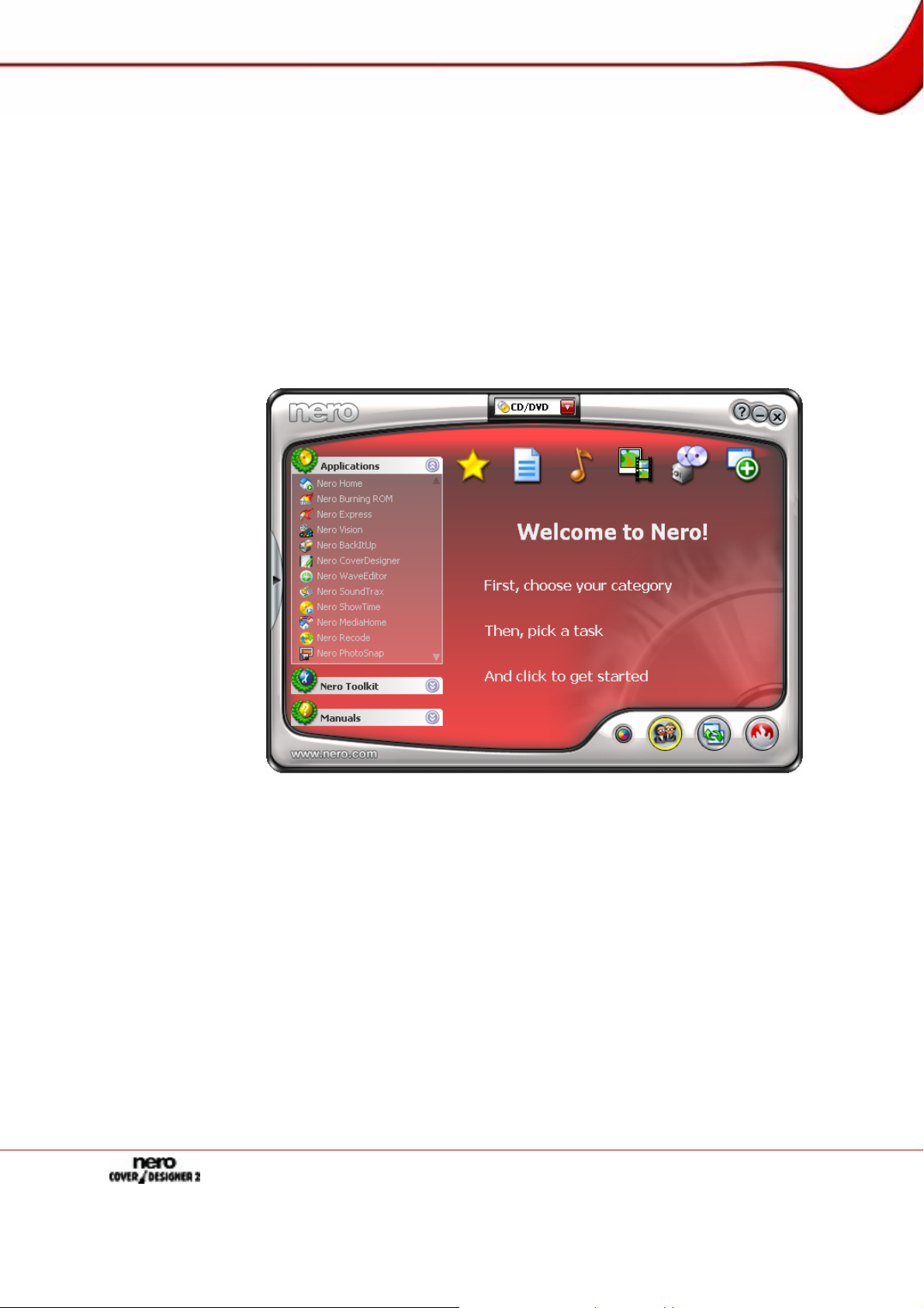
To start Nero CoverDesigner via Nero StartSmart, proceed as follows:
1. Click on the Nero StartSmart icon.
Æ The Nero StartSmart window is opened.
2. Click the arrow button in the left margin of the window.
Æ The extended dialog box is opened.
3. Select the Nero CoverDesigner entry from the Applications selection list.
Æ Nero CoverDesigner is opened with the New Document window.
Î You have started Nero CoverDesigner via Nero StartSmart.
4.2 Starting Nero CoverDesigner directly
To start Nero CoverDesigner directly, proceed as follows:
1. If you are using the Windows
(Premium) > Labels > Nero CoverDesigner. If you are using the classic Start menu, click
Start > Programs > Nero 7 (Premium) > Label > Nero CoverDesigner.
Æ Nero CoverDesigner is opened with the New Document window.
Î You have started Nero CoverDesigner.
®
XP Start menu, click Start > All Programs > Nero 7
Fig. 1: Nero StartSmart
Page 9
Page 10
Main screen
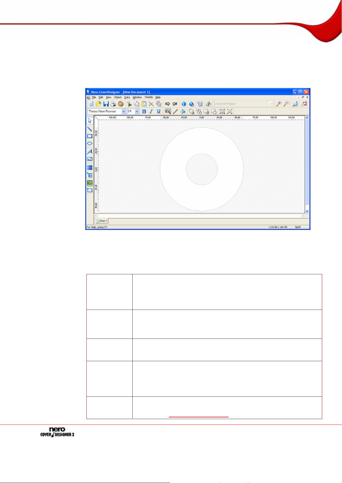
5 Main screen
The main screen of Nero CoverDesigner is the starting point for all of the actions that you
can perform with Nero CoverDesigner. The screen consists of a menu bar, several toolbars,
and the drawing area.
5.1 Menu bar
The menu bar includes the following menus:
File
Edit
View
Object
Data
Fig. 2: Main screen of Nero CoverDesigner
Opens the File menu, which provides file-related functions such as
open, save, and close. In addition, you can save files as templates,
configure your printer and paper stock, make program-specific settings, as well as import and export information from and to Nero Digital™ files.
Opens the Edit menu, which provides editing functions such as cut,
paste, duplicate, and delete. In addition, you can copy properties,
change the applied template, change the backgrounds of the cover
elements as well as add or delete cover elements as desired.
Opens the View menu, which allows you to hide and display screen
and cover elements. In addition, you can display and use grid and
guide lines as well as display objects in the editable area only.
Opens the Object menu, which you can use for editing the individual
objects of your drawing: You can insert objects, change their shape
and position, group objects, as well as open the Properties window
where you can edit the properties of objects. In addition, you can insert
a background and set default settings for objects.
Opens the Data menu with the Document Data entry, which allows
you to enter document-specific data such as the disc name or track
entries (see
Document data window).
Page 10
Page 11
Main screen
Window
TWAIN
Help
5.2 Toolbars
The following toolbars are available in Nero CoverDesigner:
Standard
View
Text
Modify Ob-
jects
Tools
Opens the Window menu, which allows you to change the position
and arrangement of multiple open documents on the main screen
(drawing area). You can also close all open documents as well.
Opens the TWAIN menu, which allows you to scan images if a scanner is attached.
Opens the Help menu, which displays the online help for specific
tasks.
Provides standard functions for the document and objects.
Allows you to zoom in or out of the drawing area. In addition, you can
select a paper stock for the current do cument.
Allows you to format text. In addition, you can choose the font and size
of the text.
Provides functions for modifying and editing objects.
Provides various tools which you can use for inserting or selecting ob-
jects in the drawing area.
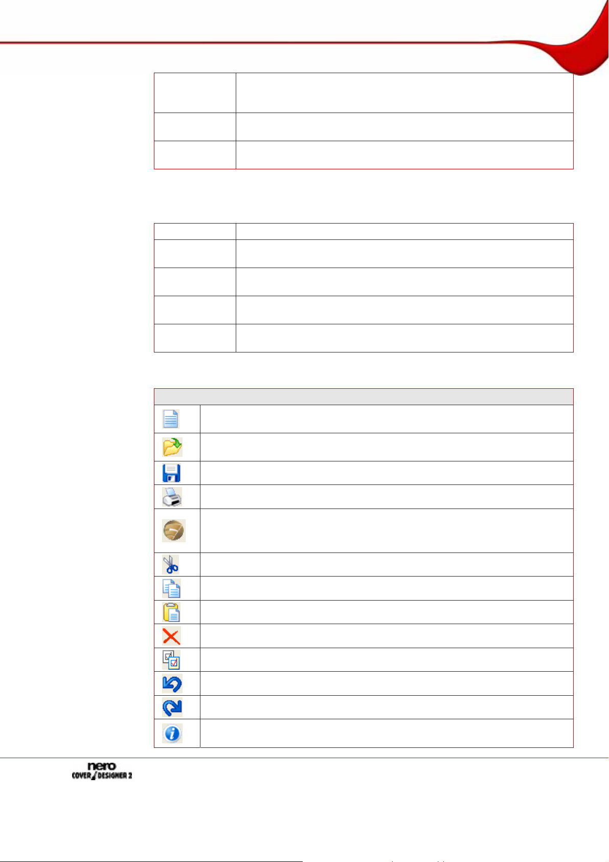
The following icons are available in the toolbars:
Standard toolbar
Opens the New Document window where you can select the document type
and template for a new document.
Opens an existing Nero CoverDesigner document or Nero CoverDesigner
template.
Saves the current Nero CoverDesigner document.
Prints the current Nero CoverDesigner document.
Opens the LightScribe Print Properties window, where you can configure
the printing options for LightScribe
This icon is only available if a LightScribe
Cuts a selected object out and stores it in the clipboard.
Copies a selected object to the clipboard.
Pastes an object from the clipboard.
Deletes a selected object.
Applies the properties of one object to another.
®
and print a LightScribe® label.
®
recorder is attached.
Undoes the last editing step.
Restores an edit that has been undone.
Opens the About Nero CoverDesigner window, where you can view the version number, for example.
Page 11
Page 12
Main screen
Opens the integrated online help.
Opens the Document Data window, where you can enter data such as the
disc title and tracks for the document (see
Opens the LabelFlash Print Properties window, where you can configure the
printing options for LabelFlash™ and print a LabelFlash™ label.
This icon is only available if a LabelFlash™ recorder is attached.
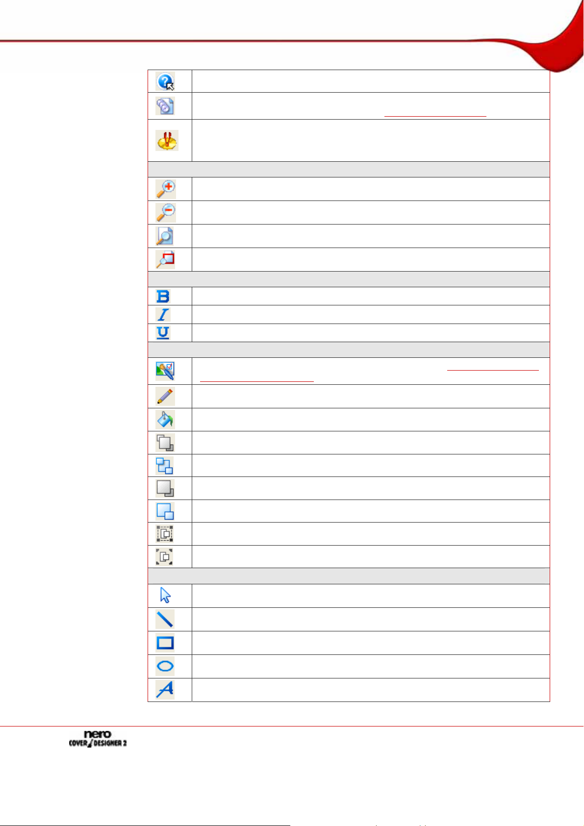
View toolbar
Magnifies the current view of the drawing area.
Reduces the current view of the drawing area.
Restores the standard view of the drawing area.
Magnifies a selected area of the drawing area.
Text toolbar
Document data window).
Changes the selected text to bold.
Changes the selected text to italics.
Underlines the selected text.
Modify Objects toolbar
Opens the Properties window for a selected object (see
ground Properties window).
Applies a margin color to the selected object.
Applies a fill color to the selected object.
Positions the selected object in front of all the others.
Moves the selected object behind all the others.
Moves the selected object one position towards the top.
Moves the selected object one position towards the back.
Groups multiple selected objects.
Ungroups objects.
Tools toolbar
Properties and Back-
Activates the selection tool, which you can use to select objects.
Activates the line tool, which you can use to insert a line.
Activates the rectangle tool, which you can use to insert a rectangle.
Activates the ellipse tool, which you can use to insert an ellipse.
Activates the text tool, which you can use to insert an artistic test.
Page 12
Page 13
Main screen
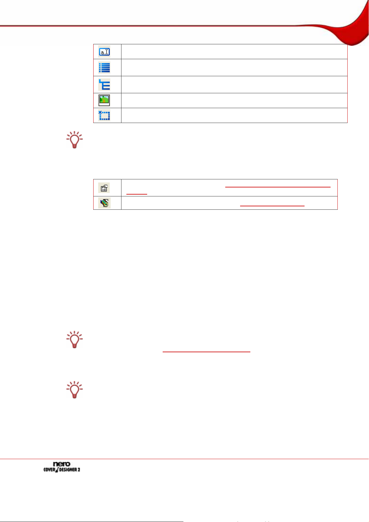
Activates the text box tool, which you can use to insert a text box.
Activates the track list tool, which you can use to insert a track list. A track list
is a list of audio files (tracks).
Activates the folder tool, which you can use to insert a folder. The folder refers
to data files.
Activates the image tool, which you can use to insert an image.
Activates the field tool, which you can use to insert different fields.
Track lists, folders, and fields are dynamic objects. The contents that are entered in the
document data are entered here. You can modify this data as well. Dynamic objects are
particularly useful for creating templates.
When you select a dynamic object and leave the cursor over the object, a floating toolbar
appears after a brief interval. The following icons are available:
Opens the Properties window (see
window
).
Properties and Background Properties
5.3 Drawing area
You lay out the cover elements in the drawing area. The drawing area consists of tabs for
the different cover elements that belong to the selected document type or that you have
added to a user-defined type, as well as the rulers at the top and on the left.
You can use the tabs in the drawing area to switch between the individual cover elements. If
you want to view multiple cover elements at the same time, you can select the cover elements that should be visible from the View menu: The drawing area will then be divided into
subwindows.
On the tabs you will find
an editable, non-crosshatched area the size and shape of the selected cover element
where the cover element is laid out, and
a crosshatched, non-editable area.
The gray line in the editable area is the edge of the cover element. The white outer margin
represents the bleed area which you can configure in the Printing tab of the Application
Preferences window (see
Bleeding means that your design is printed beyond the margin of the cover element so that
it overlaps with it. Bleeding is useful to avoid "blank streaks" that can appear when the
printout has shifted or the cover element is not trimmed precisely.
You should not place any text or important information in the bleed areas, of course. The
design, however, should be expanded to fill the bleed area in order to ensure that the design is printed completely and no blank spots appear.
Opens the Document Data window (see
Application Preferences window).
Document data window).
Page 13
Page 14

Main screen
5.4 Objects
An object in Nero CoverDesigner is a design element that can be placed in the drawing
area. Objects can be inserted, duplicated, moved, their size, shape, and appearance modified, and edited. The following objects are available in Nero CoverDesigner:
Geometric objects: line, rectangle, ellipse
Artistic text
Text box
Image
Dynamic objects: track list, folder, and fields
5.4.1 Dynamic objects
The track list, folder, and fields are dynamic objects.
These objects take the majority of their contents from the document data. Therefore, you
cannot enter text in the objects; you must enter the contents in the document data instead
Document data window).
(see
The track list takes its contents from the document data that contains the audio/chapter
data for the tracks/chapters of an audio CD. Sample contents might be an automatically
assigned sequential track number or information about the artist and/or title.
The folder takes its contents from the document data about the files from the file system
of a data CD. Sample contents might be an automatically assigned sequential number,
the path and/or file name.
Fields take their contents primarily from the document data, for example, information
about the title, artist, disc title, and/or release data. In addition, information about the save
or print date and a user-defined text entry can be displayed as well.
Page 14
Page 15
Basic steps
6 Basic steps
In order to create a cover with Nero CoverDesigner, you have to create a new document first
Creating a new document). If the document contains or should contain a track list,
(see
folder and/or fields, enter the document data (see
You can now lay out the document as desired. You can:
add cover elements if desired (see Adding a cover element),
assign another template (see Modifying a template),
insert and edit objects such as text and images on the tabs (see Inserting and editing ob-
jects), and
lay out the background (see Inserting and editing backgrounds).
Before the document is printed, you can set the print options (see
With a LightScribe
LightScribe
With a LabelFlash™ recorder and Nero CoverDesigner, you can print labels directly on LabelFlash™ discs (see
®
discs (see Printing LightScribe® labels).
Document data window).
Print window).
®
recorder and Nero CoverDesigner, you can print labels directly on
Printing Labelflash™ labels).
Page 15
Page 16
New Document window
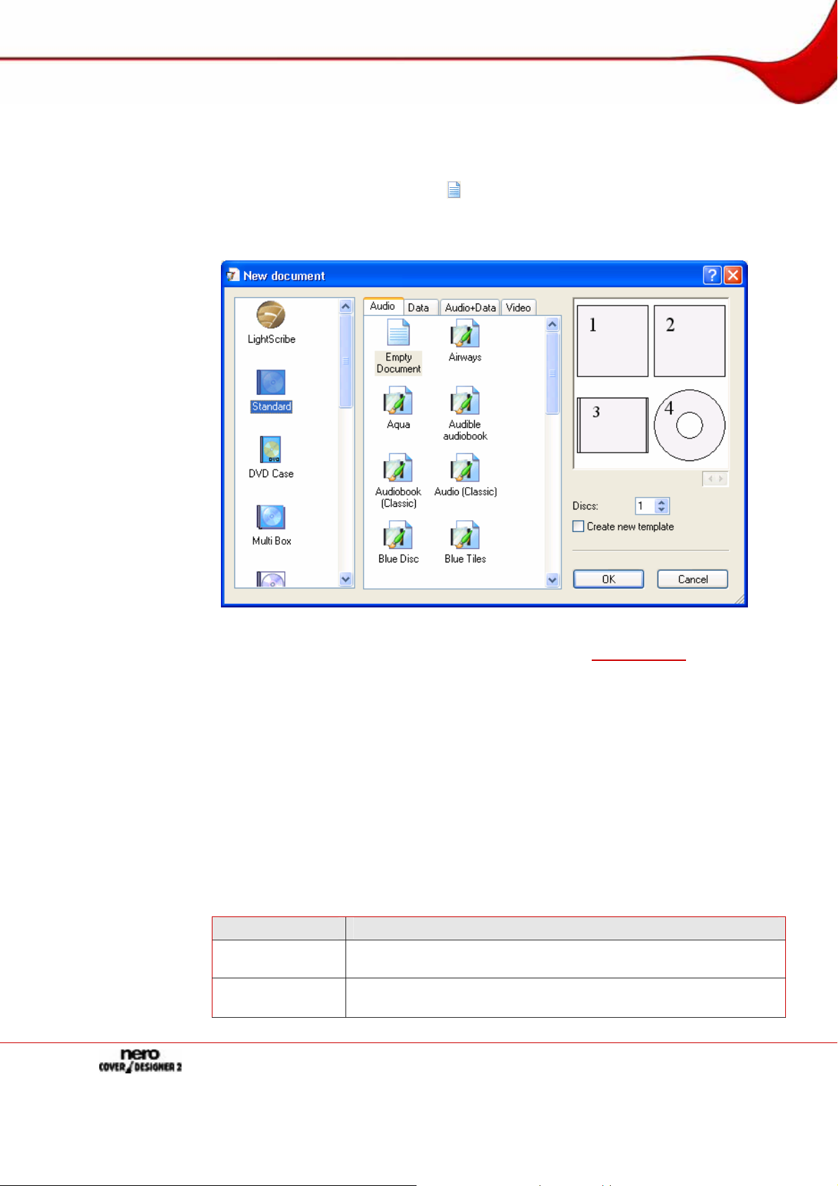
7 New Document window
When you start Nero CoverDesigner, the New Document window is automatically opened
along with the main screen. This window is your starting point for creating a new document.
You can also open the window with the
The New Document window consists of two selection lists, a preview windo w, and setting
options.
icon on the toolbar in the main screen.
Fig. 3: New Document window
The document types are displayed in the left selection list (see Document type).
Templates for the selected document type are displayed in the right selection list, and there
are four tabs available:
Audio for audio CD discs
Data for data discs
Audio+Data for audio and data discs
Video for video discs
The tabs contain templates for each disc type. The template can contain relevant fields like
the playing time, or a track list for audio CDs. The disc type is automatically correctly set in
the document data of a template.
The cover elements can be displayed with the template design in the preview window.
The following setting options are available in the New Document window:
Setting option Meaning
Discs
Create new
template
Sets the number of the Disk cover element in the document. Up to
four discs can be added to the document.
Creates a template, i.e., the document is saved in the *.nct format
and listed in the templates list.
Page 16
Page 17
New Document window
OK
Cancel
7.1 Document type
With Nero CoverDesigner, you can select different document types. Each document type
contains predefined cover elements that you can lay out. These are:
Cover Element Meaning
Booklet
Inlay
Disk Label in the form of a disc.
Mini-Disc/ (Rec-
tangular) Biz
Card
Biz Card Envelope
When you select a document type, predefined cover elements that you can lay out are
automatically added to the document.
If you would like to choose the cover elements yourself, select the Custom document type.
Here you can insert any cover element you wish into the current document with the Edit >
Insert New Page menu item.
Creates a new document and closes the window.
Cancels the process and closes the window.
Insert in the interior of the CD or DVD case as a booklet or individual sheet. Visible from the front in CD cases made from clear
plastic. Normally it contains additional information about the disc,
such as the track titles for audio CDs.
Insert in the back of the CD case. For DVD cases, a continuous
sheet that is inserted into the outer case of the DVD. The inlay is
visible from the outside.
Label in Mini-Disc/business card/rectangular business card form.
Envelope for business card.
The Full Template document type makes all the cover elements available.
Up to four discs can be added as cover elements to the Standard, DVD Case, Multi Box,
Maxi, Slim Pack and Custom document types by adding an additional disc to the document data (see
Document data window).
7.1.1 LightScribe document type
If you have a LightScribe® recorder, you can print the label side of a LightScribe® CD/DVD
with Nero CoverDesigner. The label side of the disc has a special color or thermal layer that
is heated by the laser in the recorder so that images and text are printed.
This function is only available in recorders that support LightScribe
The following element can be designed with Nero CoverDesigner:
Symbol Cover Element
Disk
®
technology.
Page 17
Page 18
New Document window
7.1.2 LabelFlash document type
If you have a LabelFlash™ recorder, you can print the label and/or data side of a LabelFlash™ DVD with Nero CoverDesigner. A LabelFlash™ DVD has a special layer between
the top and bottom layers; this layer can be heated by the laser in the recorder so that images and text can be printed on the DVD.
This function is only available with a LabelFlash™ recorder.
The following element can be designed with Nero CoverDesigner:
Symbol Cover Element
Disk
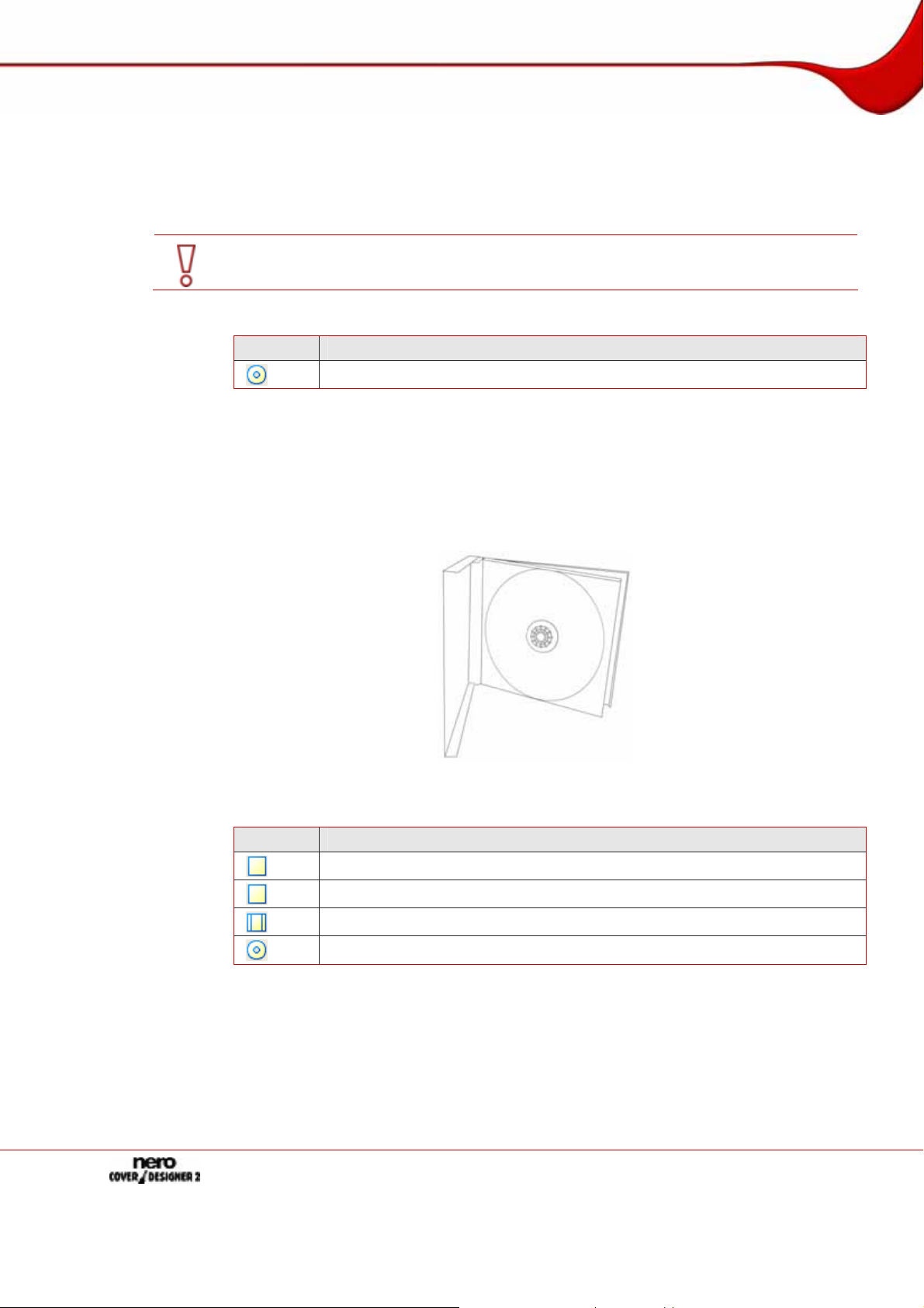
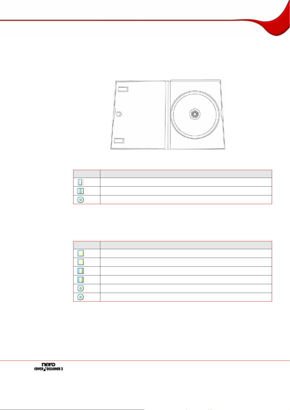
7.1.3 Standard document type
The Standard document type corresponds to the customary jewel case for CDs. Jewel case
packaging is usually made from clear plastic. The front and the back are joined by a hinge.
There is space for the booklet behind the front piece. The tray holds the CD inside. The tray
can be removed. There is room for the inlay under the tray.
The following elements can be designed with Nero CoverDesigner:
Fig. 4: Jewel case
Symbol Cover Element
Booklet (Front)
Booklet (Rear)
Inlay
Disk
Page 18
Page 19
New Document window
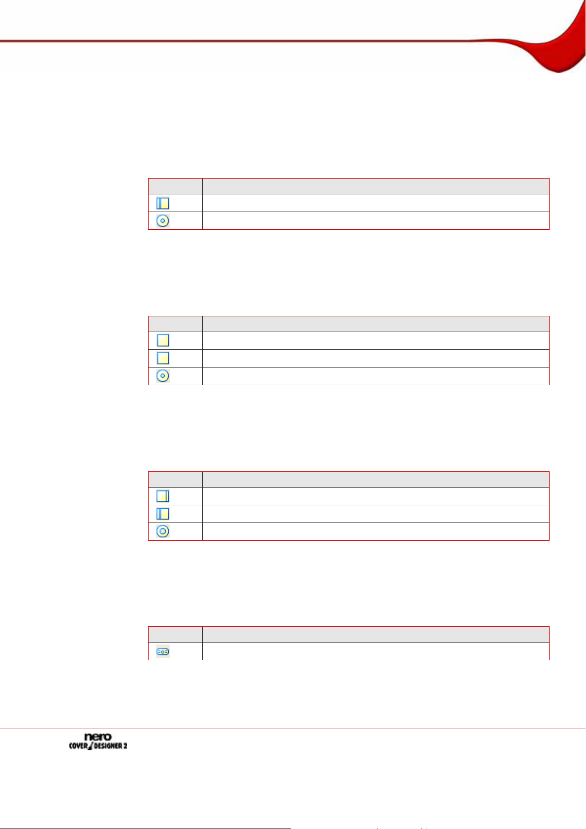
7.1.4 DVD case document type
A DVD case is type of packaging for DVDs. The packaging is larger than a normal CD case
and has a fold in the middle. The booklet is placed inside. The inlay is inserted betwee n the
plastic film and the exterior.
Fig. 5: DVD case
The following elements can be designed with Nero CoverDesigner:
Symbol Cover Element
DVD Booklet for Interior
Inlay/DVD Supplement for Case
Disk
7.1.5 Multi box document type
A multi box is a type of packaging for multiple CDs and can usually be opened on two sides.
The following elements can be designed with Nero CoverDesigner:
Symbol Cover Element
Booklet (Front)
Booklet (Rear)
Inlay (Front)
Inlay (Rear)
Disk 1
Disk 2
Page 19
Page 20
New Document window
7.1.6 Maxi document type
The maxi format was developed for single CDs, i.e., CDs that contain one track instead of an
entire album. A maxi case is thinner than a CD jewel case. Instead of a booklet it includes a
sheet that has been folded twice on the right side so that it has a legible spine. The tray that
contains the CD is integrated in the case and cannot be removed.
The following elements can be designed with Nero CoverDesigner:
Symbol Cover Element
Maxi Inlay
Disk
7.1.7 Slim pack document type
A slim pack is thinner than a maxi CD. It is designed for single CDs and data discs created at
home. Instead of a booklet it includes a single sheet that is not folded.
The following elements can be designed with Nero CoverDesigner:
Symbol Cover Element
Booklet (Front)
Booklet (Rear)
Disk
7.1.8 Mini CD document type
A mini CD is a CD with a diameter of 8 cm. Most drives have a recessed portion in the tray
for mini CDs.
The following elements can be designed with Nero CoverDesigner:
Symbol Cover Element
Mini Inlay (Front)
Mini Inlay (Rear)
Mini-Disc
7.1.9 Biz card document type
The oval biz card is also known as a business card CD and is often used for advertising purposes.
The following element can be designed with Nero CoverDesigner:
Symbol Cover Element
Biz Card
Page 20
Page 21
New Document window
7.1.10 Rectangular biz card document type
The rectangular biz card has the same format as a standard bu siness card.
The following element can be designed with Nero CoverDesigner:
Symbol Cover Element
Rectangular Biz Card
7.1.11 Biz card envelope document type
The biz card envelope is a cover for oval or rectangular biz ca rds.
The following element can be designed with Nero CoverDesigner:
Symbol Cover Element
Biz Card Envelope
Page 21
Page 22
Creating a new document
8 Creating a new document
There are three types of documents in Nero CoverDesigner. The distinguishing feature is
how the background of the cover elements is created:
Standard Document: The background is created by the user or taken from the template
as desired
Image Document: A selected image is used for all backgrounds
Nero Digital™ Document: Cover art stored in the Nero Digital™ file is used for all back-
grounds
8.1 Creating a new document or image document
To create new document or image document, proceed as follows:
1. To create a new document, click the
icon in the toolbar.
Æ The New Document window is opened.
2. To create a new image document:
1. Select File > New Cover from Picture from the menu.
Æ The Open window appears.
2. Select the desired image file and then click on the Open button.
Æ The New Document window is opened.
3. Select a document type from the left selection list (see Document type).
Æ The right selection list displays the templates for the selected document type; the Audio
tab is selected by default.
4. Click on one of the tabs in the right selection list to select a disc type.
Æ The selection list displays the templates for the selected document and disc type.
5. Select an already designed template or the Empty Document template from the selection
list on the right.
Æ The selected template is displayed in the preview area.
6. If applicable, enter the number of discs that the document should contain.
You can increase the number of discs in the document afterwards as well by adding a disc
to the document data.
7. Click on the OK button.
Æ The New Document window is closed. If you selected a template that contains dynamic
objects, the Document Data window is displayed.
8. If the Document Data was displayed, enter the document data (see Document data win-
dow), and then click OK.
Æ The document data is applied and the Document Data window is closed.
In the drawing area, the cover elements of the selected document type are displayed on
tabs. If you have created an image document, the selected image is inserted as the
background image of all the cover elements.
Page 22
Page 23

Creating a new document
Î You have created a new document and can now finish the design (see, e.g., Inserting
and editing objects
and Inserting and editing backgrounds).
8.2 Creating a Nero Digital™ document
With Nero CoverDesigner, an album cover that has been stored in a Nero Digital™ file can
be extracted and then used as a basis for a Nero CoverDesigner document.
Nero Digital™ is an MPEG-4 storage format for audio and video files that was developed
by Nero AG. Nero Digital™ files can store additional information such as album covers as
well.
To create a Nero Digital™ document, proceed as follows:
1. Select File > New Cover from Nero Digital from the menu.
Æ The Open window appears.
2. Select a Nero Digital™ file that contains a cover and then click the Open button.
Æ The New Document window is opened; the Custom document type is selected.
3. To design a cover for Nero Digital™ audio, click on the Audio tab.
To design a cover for Nero Digital™ video, click on the Video tab.
4. Select the Nero Digital Cover template.
5. Click on the OK button.
Æ The New Document window is closed. In the drawing area, the cover elements that
were stored in the Nero Digital™ file are displayed. The cover is used as the background
image.
Î You have created a new Nero Digital™docum ent and can now finish the design (see,
Inserting and editing objects and Inserting and editing backgrounds).
e.g.,
Page 23
Page 24

Editing documents
9 Editing documents
9.1 Adding a cover element
If you selected the Custom document type, only the cover element for the disc label is initially available on the Disk 1 tab. You can add new cover elements to the document, however. To do so, proceed as follows:
1. In the main screen, select Edit > Insert New Page from the menu.
Æ The Insert Page window is opened.
2. Select the cover element that you want to add to the current document.
3. Click on the Insert button.
Î The window is closed. The corresponding tab with the new cover element is added to
the document.
You can remove cover elements with the Edit > Remove Current Page menu item. A
document must contain at least one cover element, however.
9.2 Modifying a template
You can modify the template used for a document in order to select another design afterwards.
The document data of the original document remains intact but not necessarily all the inserted objects. Inserted objects are only retained if you select a template with the same
document and disc type.
To modify a template, proceed as follows:
1. In the main screen, select Edit > Change Template from the menu.
Æ The Choose New Template window appears.
2. Select a new template from the selection list on the right.
Æ The Choose New Template window is closed.
Î The document appears with the desi gn of the selected template.
Page 24
Page 25

Editing documents
9.3 Assigning a paper stock
You can assign a paper stock to every cover element. The dimensions of the cover element
may change when you do so. Assigning a paper stock usually means that you want to print
on special stock, from a particular manufacturer, for example.
If you change the size of a cover element, objects may end up outside the drawing area:
Objects are positioned absolutely in relation to the ruler, i.e., the page dimensions, and not
relative to the cover element itself.
To assign a paper stock to a cover element, proceed as follows:
1. Click on the tab that contains the desired cover element.
Æ The cover element is displayed.
2. Click on the combo box in the View toolbar.
Æ The combo box opens.
3. Select a paper stock.
Î The combo box is closed and the selected pap er stock is assigned to the cover ele-
ment. The size, dimensions, and/or position of the cover element may change.
Page 25
Page 26

Saving documents
10 Saving documents
You can save a document that you have created in Nero CoverDesigner. This saves all of
the document's cover elements and any document data that you have entered. You can
save the document in compressed or uncompressed form. Compre ssing a document primarily compresses the images in the document.
To save a document, proceed as follows:
1. To save the document as a compressed f ile, select File > Quick Save from the menu.
To save the document without compression, select File > Save from the menu.
Saving the document in compressed form may be a good idea if it contains many images.
The size of the document file will be smaller. Compression can reduce the image quality in
some cases, however.
Æ If you attempt to save a document with images that total more than 5 MB without com-
pression, a dialog window is displayed asking you whether you want to save the file with
or without compression.
The Save As window is then displayed.
2. Enter the file name and path to save the file under.
3. Click the Save button.
Î The Save As window is close d and the document is saved.
Page 26
Page 27

Document data window
11 Document data window
You can view and/or enter document data in the Document Data window. Document data
determines the content of the track list, folder, and fields dynamic objects that can be applied
when designing a cover or label. You can enter the contents, name, etc., of the disc for
which you want to create a cover or label.
When you launch Nero CoverDesigner from Nero Burning ROM, the document data is
automatically filled in with the information from the compilation.
You can import data from a Nero Digital™ file into the document data by selecting File >
Import from Nero Digital.
By default, the document data contains at least the Document, Disk 1 and a data type. You
can add additional entries yourself.
Select Data > Document Data from the menu to open the window.
Fig. 6: Document Data window
The window consists of two areas: In the area on the left, the document data elements are
displayed in a tree structure; in the area on the right, the input options for the currently selected element are displayed.
The tree structure of the document data can have up to four levels and represents the project or disc structure. You can enter information that can then be used by the dynamic objects on each level.
The top, or first level always contains the Document element, which refers to the entire project.
Page 27
Page 28

Document data window
The next level, the second one, contains the discs that are contained in the project. You can
add up to four discs to the Document element. You can specify a disc type for each disc;
this entry affects the third and fourth levels. There are four disc types you can choose from:
Audio for audio CD disc types
Data for data discs
Audio+Data for audio and data discs
Video for video discs
By default, the disc type that you selected when you created the document in the New
Document window is used for the discs.
The third level contains the data type or types that that are contained on the disc of the selected type. An audio CD, for example, contains audio files – in other words, the data type
Audio/Chapter Data. A data disc contains pure data – in other words, the data type File
System.
The fourth level contains the contents of the disc under its corresponding data type. Audio
files (tracks), for example, are listed under Audio/Chapter Data, and data files unde r the
File System data type.
11.1 Document
For the Document element, the following input options are available in the Document area
on the right:
Title
Year of release
Artist/Publisher
Apply to all
subitems
Add Disc
11.2 Disk
For the Disk element, the following input options are available in the Disk area on the right:
Subtitle
Type
Artist/Publisher
Specifies the title of the document. By the default, the document
title is applied to the Subtitle input field for the disc as well.
This information is used for the Title field type.
Specifies the release year.
This information is used for the Year field type.
Specifies the artist or publisher.
This information is used for the Artist field type.
Applies the artist or publisher entry to the corresponding input
fields Artist/Publisher for the Disc and Artist for the Tracks.
Adds a disc to the document data. Up to four discs can be
added. The corresponding tabs from Disc 1 to Disc 4 with the
new cover element for the disc label are added to the document.
Specifies the title of the disc. By default, the document title is
applied to the input field.
This information is used for the Disc Title field type.
Specifies the disc type. Four types are available: Audio, Data,
Audio+Data and Video. Depending on the selected disc type,
the disc will contain different data types on the next level.
This information is used for the Disc Type field.
Specifies the artist or publisher of the disc.
This information is used for the Disc Artist field type.
Page 28
Page 29

Document data window
Apply to all
subitems
Delete
Import Data
A CDC file is a text file that can contain information about discs such as the track titles. A
number of programs exist that can generate a CDC file.
11.3 Data type
11.3.1 Audio/chapter data
Audio/Chapter Data appears as an entry for Audio, Audio+Data and Video disc types. I n -
formation about the track number and total playing time is displayed in the Audio/Chapter
Data area on the right. The following buttons are available:
Add Track
Delete All
Applies the artist or publisher entry to the Artist input field for
the tracks.
Deletes the disc from the document data and its corresponding
tab from the document.
Opens the Read In An Import File window that you can use to
select a CDC file.
Adds a track entry to the data.
Deletes all tracks from the data.
11.3.2 File system
File System appears as an entry for Data, Audio+Data and Video disc types. Information
about the number of entries and the total size is displayed in the File System area on the
right. The following buttons are available:
Add Files
Delete All
Add Folder
11.3.3 Video/picture data
Video/Picture Data appears as an entry for the Video disc type. The number of images is
displayed in the Video/Screenshot Data area on the right. The following buttons are available:
Add Picture
Delete All
When you add an entry to the data, the information from the entry is applied to the document data and data structure is expanded accordingly.
If you add an image, the image is stored in the document as well. Tracks, folders, and data
files are not stored in the document.
Opens the Select the Files You Want to Add to the Disc window so that you can select a file. A new entry is added to the
data and the file information is automatically applied.
Deletes all file entries from the data.
Opens the Browse for Folder window so that you can select a
folder. The folder is added to the data as a file entry.
Displays the Open window so that you can select an image. A
new entry is added to the data and the file information is automatically applied; the image is stored in the Nero CoverDesigner
document.
Deletes all file entries from the data.
Page 29
Page 30

Document data window
11.4 Data entry
11.4.1 Track/Chapter
For the Track/Chapter data entry, the following input options are available in the Audio
Track area on the right:
Title
Artist
Playing Time
Extended info
Delete
11.4.2 File Information
For the File Information data entry, the size and path of the file are displayed in the Audio
Track area on the right. The following input options are available:
Title
Delete
Specifies the title of the track.
Specifies the artist of the track.
Specifies the playing time of the track.
Provides additional information about the track.
Deletes the track entry.
Specifies the title of the file.
Deletes the file entry.
11.4.3 Image
For the Picture File data entry, the following input options are available in the area on the
right:
Title
Delete
Specifies the title of the image.
Deletes the image entry.
Page 30
Page 31

Properties and Background Properties window
12 Properties and Background Properties window
The Properties or Background Properties window offers numerous setting options for objects and the background. Different tabs are available depedending on the currently selected
object.
The Properties window for a selected object can be opened with the
the object by modifying the setting options in the window (see
Inserting and editing objects).
icon. You can edit
The Background Properties window can be opened for all backgrounds by selecting Edit
> Change All Backgrounds or for the background of the current cover element by selecting
Object > Background Properties from the menu. You can insert and edit the background
with the setting options in the window (see
Inserting and editing backgrounds).
The following tabs are available:
Tab Explanation
Specifies whether the object has an outline. You can set the width and
Pen
color as well (see
Pen tab).
This tab is available for all objects.
Specifies whether or not the object is filled and with what color. You can
Brush
set the style and color as well (see
This tab is available for the rectangle, ellipse, artistic text, text box, track
Brush tab).
list, folder, and field objects as well as the background.
Text
Determines the content and options for the text (see
This tab is available for the text and field objects.
Text tab).
Determines the font, style, and size of the text. In addition, you can chose
Font
whether the text should be displayed in strikeout, underline and/or small
caps. A preview window displays your changes.
This tab is available for the text and field objects.
Text Box
Bend
Image
Allows you to enter and format text (see
This tab is available for the text box object.
Bends the object (see
Bend tab).
This tab is available for the text box, track list, and folder objects.
Allows you to select and edit an image (see
This tab is available for the image, text box, track list, and folder objects as
Text Box tab).
Image tab).
well as the background.
Provides import functions for images (see
Import Picture tab). This feature
is particularly useful for creating templates.
Import
Image
For example, here you can determine whether a preview image is automatically displayed when you start Nero CoverDesigner from Nero Burning
ROM and have created a compilation with the Audio Book CD disc format.
This tab is available for the image object.
Allows you to import a commentary.
This function is only performed when you start Nero CoverDesigner from
Import
Text
Nero Burning ROM and have created a compilation with the Audio Book
CD disc format.
This feature is particularly useful for creating templates for Audio Book
CDs.
This tab is available for the text box object.
Page 31
Page 32

Properties and Background Properties window
12.1 Pen tab
The Pen tab provides settings for the object outline. The following setting options are available:
Tracks
Folder
Field
Width
Color
Color Circle
Provides options for the contents and appearance of the track list (see
Tracks and Folder tabs).
Provides options for the contents and appearance of the folder (see
Tracks and Folder tabs).
Provides options for the contents and appearance of fields (see
Field tab).
Activates the outline.
Determines the width of the outline.
Shows the color of the outline. You can set the color with the color
circle, brightness slider, or the input fields in the Select Color
area.
Determines the color of the outline. You can move the small
square in the middle of the color circle. This determines the color.
You can see which color has been selected in the Color display
field.
Brightness Slider
Hue
Saturation
Brightness
Red
Green
Blue
Determines the brightness of the outline color. You set the desired
value with the slider.
You can see the brightness that has been selected in the Color
display field.
Sets the hue. You can enter a value between 0 and 255. The
square moves around the radius of the color circle counterclockwise beginning on the right with the value 0 = red.
Defines the saturation of the color. You can enter a value between
0 and 255. The square moves across the color circle in a straight
line towards the exterior. A saturation of 255 means that one color
component has a value of 255 and the other two both have a value
of 0.
Determines the brightness of the outline color. You can enter a
value between 0 and 255. The brightness slider moves up or
down. 255 means maximum brightness.
Defines the red component of the color. You can enter a value between 0 and 255. The maximum red value is 255.
Defines the green component of the color. You can enter a value
between 0 and 255. The maximum green value is 255.
Defines the blue component of the color. You can enter a value
between 0 and 255. The maximum blue value is 255.
Page 32
Page 33

Properties and Background Properties window
If the red, green, and blue components are equal, then the outline color is black (brightness
0), white (brightness 255), or gray (brightness value between 0 and 255).
12.2 Brush tab
The Brush tab provides fill setting options.
The following setting options are available:
Activates the fill.
Style
When the brush option is deactivated, the background of the object is transparent.
Selects a style. A style is always a mixture of two colors: the foreground and background color. No style is selected by default.
Displays the foreground color. Click on the button to change the
Foreground
foreground color, i.e., apply any changes you make in the Select
Colour area to the foreground color.
The button displays the fill color if no style has been selected.
Displays the background color. Click on the button to change the
Background
background color, i.e., apply any changes you make in the Select
Colour area to the background color.
The button is grayed out if no style has been selected.
Color Circle
Determines the fill color. You can move the small square in the
middle of the color circle. This determines the color.
You can see which color has been selected in the Color display
field.
Fig. 7: Properties window, Brush tab
Page 33
Page 34

Properties and Background Properties window
Brightness Slider
Determines the brightness of the fill color. You set the desired
value with the slider.
You can see the brightness that has been selected in the Color
display field.
Sets the hue. You can enter a value between 0 and 255. The
Hue
square moves around the radius of the color circle counterclockwise beginning on the right with the value 0 = red.
Defines the saturation of the color. You can enter a value between 0 and 255. The square moves across the color circle in a
Saturation
straight line towards the exterior. A saturation of 255 means that
one color component has a value of 255 and the other two both
have a value of 0.
Determines the brightness of the color. You can enter a value be-
Brightness
tween 0 and 255. The brightness slider moves up or down. 255
means maximum brightness.
Red
Green
Blue
Defines the red component of the color. You can enter a value
between 0 and 255. The maximum red value is 255.
Defines the green component of the color. You can enter a value
between 0 and 255. The maximum green value is 255.
Defines the blue component of the color. You can enter a value
between 0 and 255. The maximum blue value is 255.
12.3 Text tab
The Text tab provides setting options and determines the content of text and field objects.
The following setting options are available:
Read-Only
Bent
Rotate the text
by 180 degrees
Content
If the input field in the Content area is grayed out, the text can no
longer be modified. This option is particularly useful when you are
creating templates (see
Creating and modifying templates).
Bends the text with the lower edge around a midpoint.
Rotates the text by 180 degrees, i.e., the text is rotated with its top
edge around the midpoint.
This option is only available if the Bent check box is selected.
Defines the contents of the text.
For field objects, this option is grayed out because the contents
are dynamically generated from the document data (see
Document data window).
Page 34
Page 35

Properties and Background Properties window
12.4 Text Box tab
You enter the contents of the text box on the Text Box tab. Unlike artistic text, a line break is
possible in a text box. The usual text editing options are available: font and size selection,
bold face, italics, underline, align, color, copy, and paste. The following check boxes are
available:
Fit to shape
Displays the text in the editable area only, even if the text box lies
partially outside. The font size is not changed.
Grays out the contents of the tab so that the text can no longer be
Read-only
modified. This option is particularly useful when you are creating
templates (see
12.5 Bend tab
The following check boxes are available on the Bend tab:
Creating and modifying templates).
Bend object
Rotate the text
by 180 degrees
12.6 Image tab
On the Image tab, you can select an image and edit it if you wish. A preview of the image is
displayed in the Image area. The Name field displays the name of the file.
Bends the text with the lower edge around a midpoint.
Rotates the text by 180 degrees, i.e., the text is rotated with its
top edge around the midpoint.
This option is only available if the Bend object check box is se-
lected.
Fig. 8: Properties window, Image tab
Page 35
Page 36

Properties and Background Properties window
The following setting options are available:
Effects
Remove Image
Opens a menu where you can select different effects to apply to
the image (see
Removes the image.
Image Source Area
File
TWAIN
Displays the Open browser window so that you can select an image file.
Scans an image.
This feature is only listed if you have a scanner installed.
Stretch Mode Area
This area is available for the background and images that were imported on the Import
Picture tab.
Adjusts the image to match the background or frame size.
Adjust to frame
size
If the background or frame is larger or smaller than the image, the
image is expanded or reduced in size accordingly. This means
that the width and/or length of the image may be distorted.
Adjusts the image proportionally to the background or frame size;
the ratio of the width and length of the image (aspect ratio) re-
Proportional, no
clipping
mains the same.
If the background or frame is larger or smaller than the image,
blank areas may appear above/below or on the left/right of the
image. The longest side determines how the image is resized.
Adjusts the image proportionally to the background or frame size;
the ratio of the width and length of the image (aspect ratio) re-
Proportional, clip
image
mains the same.
If the background or frame is larger or smaller than the image,
areas may be clipped above/below or on the left/right of the im-
age. The shortest side determines how the image is resized.
Image effects).
12.6.1 Image effects
Nero CoverDesigner offers a variety of effects for images: The following effects are available:
Color adjustment
Brightness
Contrast
Gamma .
Equalize
Opens the Brightness window with before and after views of the
image. Move the Brightness slider left or right to darken or
lighten the image.
Opens the Contrast window with before and after views of the
image. Move the Contrast slider left or right to increase or de-
crease the contrast of the image.
Opens the Gamma window with before and after views of the im-
age. Move the Gamma slider left or right to darken or lighten the
midtones of the image.
Applies the Equalize effect to an image. This effect distributes
the brightness values of the colors equally.
This effect is appropriate for adjusting an image that is too light or
dark. It is also useful for making objects in the shadows more
visible.
Page 36
Page 37

Properties and Background Properties window
Filter
Emboss
Erode
Creates an embossed version of the image.
Generates a watercolor version of the image, making the image
softer and coarser.
Opens the Mosaic window with before and after views of the im-
Mosaic
age. Move the Mosaic slider to the right to make the image
coarser, creating a mosaic effect.
Outline
Parabolic >
Concave
Parabolic >
Convex
Draws the edges of the surfaces in the image, generating an out-
line effect.
Generates a concave view.
Generates a convex view.
Opens the Posterize window with before and after views of the
Posterize
image. Move the Posterize slider right or left to create an oil
painting effect.
Opens the Sharpen window with before and after views of the
Sharpen
image. Move the Sharpness slider to the right to make the image
sharper and harder.
Opens the Soften window with before and after views of the im-
Soften
age. Move the Soften slider to the right to make the image softer
and less focused. In doing so, areas are merged together.
Opens the Solarize window with before and after views of the
Solarize
image. Move the Solarize slider to the left to strengthen the light-
ing effect. Move the slider completely to the left to invert the val-
ues and create a negative.
Flip
Horizontal
Vertical
Negative
Flips the image horizontally, the image appears as a mirrored im-
age.
Flips the image vertically, the image appears upside down.
Creates a negative of the image.
Opens the Pinch window with before and after views of the im-
Pinch
age. Move the Pinch slider right or left to pinch or bloat the image
in the middle.
Opens the Swirl window with before and after views of the im-
Swirl
age. Move the Swirl slider right or left to swirl the image to the
right or left.
Opens the Rotate window with before and after views of the im-
Rotate
age. Move the Rotate slider to the right to rotate the image 90°,
180° or 270°.
Page 37
Page 38

Properties and Background Properties window
12.7 Import Picture tab
The Import Picture tab provides the following setting options:
Import picture, if
possible
Picture to import
Import Original
Picture
Activates the Picture to import combo box.
Selects the image that should be imported. The following entries
are available:
Nothing: No image is imported.
Thumbnail: Imports a preview image when you start Nero
CoverDesigner from Nero Burning ROM and have created a
compilation with the Audio Book CD disc format. This feature is
particularly useful for creating templates for Audio Book CDs.
Video Picture: Imports an image that you have added to the
Video/Picture Data entry in the document data. You can deter-
mine which image is imported with the Disc Number and Picture
Number fields.
Cover Art: Imports an image from a Nero Digital™ file (if it is
technically possible).
Imports the specified image. If the image has been modified, you
can use this button to import the original image again.
12.8 Tracks and Folder tabs
In the Tracks and Folder tabs, you can determine the appearance of the track list or folder
and select which contents are displayed. The track list contains information from audio files,
the folder contains information from data files. You cannot enter text in the track list/folder
yourself – the contents are taken from the document data.
Three areas and one check box are available:
Fig. 9: Properties window, Tracks tab
Show sample window
Opens the Sample preview window.
Data Area
Disc
Species the disc that the information should be taken from.
Page 38
Page 39

Properties and Background Properties window
First Track/Entry
Last Track/Entry
Specifies the audio/data file from which the track list/folder
should begin.
Specifies the audio/data file at which the track list/folder
should end.
Format Area
Style
Column Spacing
Alignment
Selects a predefined style with which to display the track
list/folder. The style can be modified in the Fields area.
Sets the column spacing in percent.
Specifies the alignment of the text.
Displays the text in the editable area only, even if the track
Fit text to shape
list/folder lies partially outside. The font size is adjusted if
necessary.
Fields Area
Displays the fields that are available in the selected style,
such as track number or file path. The meaning of each column is as follows:
Use: The field is visible in the track list/folder. If the check
Selection List
box is not selected, the field is not visible in the track
list/folder.
Column: Displays the column that the field will be displayed
in.
Field Type: Displays the field type, e.g., track number or
title.
Selects a format for the selected field.
Text can be displayed in normal, uppercase, lowercase, or
reverse.
Left Combo Box
Numbers can be displayed as single, double digits, or in
Roman numerals.
Playing times can be displayed in different formats, e.g., in
seconds, M:SS, H:MM:SS, etc.
File sizes can be displayed in bytes, KB or MB.
Right Combo Box
Selects an alignment for the selected field. The alignment
always refers to the full column that the field is in.
Opens the Choose Color window so that you can define a
Color Button
color for the selected field. The window is the same as the
one for the Select Color area on the Pen and Brush tabs
Pen tab).
(see
The button shows the currently selected color.
Opens the Font window so that you can choose a font,
Font Button
style, and effects for the selected field. You can also specify
the character set to use in the Script combo box. A preview
of the text is displayed in the Sample area.
The button displays the currently selected font.
Input Field Specifies a relative font size in percent for the selected field.
Leading Text
Trailing Text
Specifies the text that appears in front of the selected field
in the track list/folder.
Specifies the text that appears after the selected field in the
track list/folder.
Page 39
Page 40

Properties and Background Properties window
12.9 Field tab
The Field tab provides setting options for fields. Fields take their content from the document
data for the most part. The Field tab consists of the Field Type selection list, the Options
area, and a check box.
All of the field types are listed in the Field Type selection list. The Options area refers to the
selected field type. Not all setting options are available for each field type. The following setting options are generally available:
Specifies the field type. The following field types are available:
Field Type Area
Fixed Size
Options Area
Alignment
Disc
Time Format
Size Format
Date Format
Custom Text
Leading Text
Trailing Text
The field type that you select in the Field Type selection list is applied to the inserted field
even if you assigned a different field type beforehand.
Title, Artist, Disc Type, Year, Disc Title, Disc Artist, Number of
Tracks, Total Playing Time, Total Size of Files, Last Save Date,
Print Date, and Custom Text.
Specifies that the text has a fixed height even if the size of the
frame is modified. The text height is based on the font size that is
specified on the Font tab.
If the check box is not selected, the text size is adjusted to match
the frame size and vice versa.
This feature is not available for bent text.
Specifies the alignment of the selected field type in the frame.
Specifies which disc the selected field type refers to.
Specifies the format for the playing time.
Specifies the format for the file size.
Specifies the format for the date.
Specifies the text for the Custom Text field type.
Specifies the text that appears in front of the selected field type.
Specifies the text that appears after the selected field type.
Page 40
Page 41

Geometry window
13 Geometry window
The position, size, and rotation of an object are determined in the Geometry window. To
open the window, select Object > Geometry from the menu.
The window contains the following fields:
Fig. 10: Geometry window
Position Area
X
Y
Size Area
Width
Height
Rotation Area
Angle
Specifies the X coordinate of the top left point of the frame.
Specifies the Y coordinate of the top left point of the frame.
Specifies the width of the object in mm.
Specifies the height of the object in mm.
Specifies the angle of rotation.
Page 41
Page 42

Geometry window
13.1 Geometry window for bent objects
For bent objects, the position of the center and the position of the object in terms of the center are specified in the Geometry window. To open the window, select Object > Geometry
from the menu.
The window contains the following fields:
Center Area
X
Y
Rotation Area
Start
Arc
Specifies the X coordinate of the center point (which the object
is rotated around).
Specifies the Y coordinate of the center point (which the object
is rotated around).
Specifies the position of the text in relation to the center point.
The starting point of the text is the left edge of the first character.
The division into degrees is the one commonly used in mathematics: 0 degrees is on the right at the height of the midpoint
and the units progress in a counterclockwise direction.
Specifies the arc to apply to the text. Selecting 180 degress, for
example, bends the text in a semicircle.
Fig. 11: Geometry window for bent objects
Page 42
Page 43

Align Elements window
14 Align Elements window
The Align Elements window aligns objects relative to the page, i.e., the editable drawing
area, or another object. To open the window, select Object > Align from the menu.
This feature is not available for bent objects.
The window contains the following check boxes and option buttons:
Specifies the horizontal alignment. There are three option buttons:
Horizontal Alignment
Left: Aligns the object along the left edge.
Center: Centers the object.
Right: Aligns the object along the right edge.
Specifies the vertical alignment. There are three option
buttons:
Vertical Alignment
Top: Aligns the object along the top edge.
Center: Centers the object.
Bottom: Aligns the object along the bottom edge.
Align To
Aligns the object with another. In order to use this feature, two objects must be selected; the object that was
Last Selected Element
selected last will be aligned in relation to the first.
This feature is useful for positioning two objects on top
of one another, e.g., text on an image.
Page
Aligns the object to the page, i.e., to the editable area.
Fig. 12: Align Elements window
Page 43
Page 44

Inserting and editing objects
15 Inserting and editing objects
In Nero CoverDesigner, you can insert objects in order to design co ver elements for a document. An inserted object is automatically selected and can be edited.
15.1 Inserting object
To design a cover element, you can insert objects in the drawing area. To do so, proceed as
follows:
1. To insert a line:
1. Click the
Æ The cursor changes to a crosshair with a line symbol.
2. Click in the drawing area and drag the cursor.
Æ The line is inserted.
icon on the toolbar.
2. To insert a rectangle:
1. Click the
Æ The cursor changes to a crosshair with a rectangle symbol.
2. Click in the drawing area and drag the cursor.
Æ The rectangle is inserted.
icon on the toolbar.
3. To insert an ellipse:
1. Click the
Æ The cursor changes to a crosshair with an ellipse symbol.
2. Click in the drawing area and drag the cursor.
Æ The ellipse is inserted.
icon on the toolbar.
4. To insert artistic text:
1. Click the
Æ The cursor changes to a crosshair with an A.
2. Click in the drawing area.
Æ A vertical line is inserted.
3. Enter the text directly in the drawing area.
You cannot enter artistic text with a line break. To enter longer text with line breaks, use the
text box object.
4. Press the Enter key.
icon on the toolbar.
5. To insert a text box:
1. Click the
Æ The cursor changes to a crosshair with "Abc".
icon on the toolbar.
Page 44
Page 45

Inserting and editing objects
2. Click in the drawing area and drag the cursor.
Æ The Properties window is opened at the Text Box tab (see
3. Enter the text in the input area.
4. Specify the text options.
5. Click on the OK button.
Æ The text box is inserted with the text that you entered.
Text Box tab).
6. To insert a track list or folder:
1. Click the
Æ The cursor changes to a crosshair with a track list or folder symbol.
2. Click in the drawing area and drag the cursor.
Æ The track list or folder is inserted. If you have completed the document data, the cor-
responding contents are displayed (see
or icon on the toolbar.
Document data window).
7. To insert an image:
1. Click the
Æ The Open browser window is displayed.
2. Select an image file and then click on the Open button.
Æ The Open window is closed. The cursor changes to a crosshair with a camera sym-
bol, and the frame of the selected image is displayed around the pointer.
icon on the toolbar.
3. Click in the drawing area.
Æ The selected image is inserted.
8. To insert a field:
1. Click the
Æ The extended dialog box is opened and displays the field types.
2. Select a field type.
Æ The cursor changes to a crosshair and an outline of the selected field is displayed in
the background.
3. Click in the drawing area.
Æ The field is inserted. If you have completed the document data, the corresponding
contents are displayed (see
the field type name is displayed in angled brackets.
The inserted object is automatically selected and displays a frame with the anchor points of
the frame and a rotation arrow.
icon on the toolbar.
Document data window). If the document data is empty,
Î You have successfully inserted an object. Now you can edit it and continue designing
the cover.
Page 45
Page 46

Inserting and editing objects
15.2 Modifying size, shape, and position
You can edit an inserted object with Nero CoverDesigner. You can modify the size, shape,
position, and, if desired, color. There are always two ways to modify the size, shape, and position of an object:
Precision changes, in which the settings are made in the Geometry, Align Elements
and/or Properties window.
Manual changes, in which objects are moved, transformed, and rotated using their
frames, anchor points, and a rotation arrow.
To edit an object, proceed as follows:
1. Click the icon (selection tool) on the toolbar.
2. Select the object that you want to edit.
Æ A frame with anchor points and a rotation arrow are displayed around the object.
Fig. 13: Selected object
3. To change the position, size, and/or rotation of an object precisely:
1. Select Object -> Geometry from the menu.
Æ The Geometry window appears.
2. Enter the desired position, size, and rotation (see
3. Click on the OK button.
Æ The window is closed and the object is modified according to your new entries.
Geometry window).
4. To align an object precisely in the drawing area:
1. Select Object -> Align from the menu.
Æ The Align Elements window is displayed.
2. Set the desired options (see
3. Click on the OK button.
Æ The window is closed and the object is positioned according to your ne w entries.
Align Elements window).
5. To change the position of an object manually, hold down the mouse button and move the ob-
ject.
With bent objects, you can use this technique to change the position and bend in relation to
the midpoint.
6. To change the position of the midpoint of a bent text:
1. Click on the midpoint.
Æ The cursor changes to a crosshair.
2. Move the midpoint while holding down the mouse button.
Page 46
Page 47

Inserting and editing objects
Æ The position of the midpoint is modified.
7. To change the size or shape of an object manually:
1. Move the cursor over an anchor point on the frame.
Æ The cursor changes to a double arrow that shows you the direction in which you can pull
the object.
2. Click on the anchor point and pull it in the desired direction.
Æ The object becomes larger or smaller.
With bent objects, you can use this technique to change the arc that the text follows.
8. To change the rotation of an object manually:
1. Move the cursor over the rotation arrow of the frame.
Æ The cursor changes to a rotation arrow.
2. Click on the rotation arrow and rotate the object in the desired direction.
Æ The rotation of the object is changed.
9. To change properties such as the pen, brush, font, etc.:
1. Click on the
Æ The Properties window is displayed. The tabs in the window can vary depending on
the currently selected object.
2. Specify the properties in the tabs (see
3. Click on the OK button.
Æ The window is closed and the object is modified to match your new entries.
icon.
10. To change the contents of artistic text:
1. Click the
Æ The cursor changes to a crosshair with an A.
2. Click on the artistic text and change the content as desired.
3. Press the Enter key.
icon on the toolbar.
Î You have edited the object.
15.3 Converting artistic text
With Nero CoverDesigner, you can convert artistic text to a graphic element. The text properties can no longer be edited after the conversion. To convert artistic text, proceed as follows:
Properties and Background Properties window).
1. Click the icon (selection tool) on the toolbar.
2. Select the artistic text that you want to convert.
Æ A frame with anchor points and a rotation arrow are displayed around the text.
3. Select Convert to Curves in the context menu.
Page 47
Page 48

Inserting and editing objects
Æ A dialog window is displayed that informs you that the text will be converted to a graphic
element and that you will no longer be able to edit the text properties.
4. Click on the OK button.
Æ The dialog window is closed, and the artistic text is converted.
Î You have successfully converted artistic text to a graphic element. The Pen and Brush
tabs are available in the Properties window.
15.4 Applying image effects
In Nero CoverDesigner, you can apply a wide range of effects to images. To do so, proceed
as follows:
1. Click the icon (selection tool) on the toolbar.
2. Select the image that you want to edit.
Æ A frame with anchor points and a rotation arrow are displayed around the text.
3. Click on the icon.
Æ The Properties window is displayed.
4. Click on the Effects button.
Æ A menu is displayed.
5. Choose the desired effect (see Image effects).
Æ The corresponding effect window with before and after views of the image is displayed.
For some effects, no window is displayed; the effect is applied immediately instead, like
with Negative, for example.
6. Select the desired value with the slider.
7. Click on the OK button.
Æ The window is closed.
The Image area displays the current view of the image.
8. Add additional effects if you wish.
9. Click on the OK button.
Î The Properties window is closed.
The image in the drawing area is modified to match your new entries.
If you are not satisfied with the effect(s), you can undo your last action(s) with the
on the toolbar.
The number of actions that you can undo depends on the value that was entered in the
Application Preferences. You can change this value in the Application Preferences window (see
Application Preferences window).
icon
Page 48
Page 49

Inserting and editing objects
15.5 Specifying default settings for objects
In Nero CoverDesigner, you can specify default settings for objects. The default settings determine the entries in the tabs of the Properties window for an object (see
Background Properties window
Default settings cannot be specified for images.
To specify default settings for objects, proceed as follows:
1. To specify default settings for geometric objects:
1. Select Object > Default Graphic Properties from the menu.
Æ The Default Properties window with the Pen and Brush tabs is displayed.
).
Properties and
2. Specify the desired properties in the tabs (see
dow).
3. Click on the OK button.
Æ The window is closed. Geometric objects will now be inserted with the selected prop-
erties by default.
Properties and Background Properties win-
2. To specify default settings for artistic text and fields:
1. Select Object > Default Artistic Text Properties from the menu.
Æ The Default Properties window with the Pen, Brush, Font, and Field tabs is dis-
played.
2. Specify the desired properties in the tabs (see
dow).
3. Click on the OK button.
Æ The window is closed. Artistic text and fields will now be inserted with the selected
properties by default.
Properties and Background Properties win-
3. To specify default settings for text boxes, track lists, and folder:
1. Select Object > Default Text Box Properties from the menu.
Æ The Default Properties window with the Pen, Brush, Folder, and Tracks tabs is
displayed.
2. Specify the desired properties in the tabs (see
dow).
3. Click on the OK button.
Properties and Background Properties win-
Æ The window is closed. Text boxes, track lists, and folders will now be inserted with
the selected properties by default.
Some of the changes that you make in the tabs may not apply to all objects under some
circumstances.
Î You have successfully configured the default settings for objects.
Page 49
Page 50

Inserting and editing backgrounds
16 Inserting and editing backgrounds
In Nero CoverDesigner, you can insert and edit a background. You can insert or edit the
backgrounds for all the cover elements of a document at the same time or insert or edit the
background of a cover element separately.
To insert a background and edit its properties, proceed as follows:
1. To insert or edit the background for the current cover element, select Object > Background
Properties from the menu.
To insert or edit the background for all the cover elements of the document, select Edit >
Change All Backgrounds from the menu.
Æ The Background Properties window is displayed.
2. To create a colored background:
1. Click on the Brush tab.
2. Select a color and a style, if desired (see
3. To insert a background image:
1. Click on the Image tab.
2. Select an image file in the Image Source area.
Brush tab).
Æ The image is displayed in the Image preview area. The Stretch Mode area is active.
3. In the Stretch Mode area, specify how the background image is scaled (see
4. Apply any desired effects to the image (see
Image effects).
4. Click on the OK button.
Î The background is displayed according to your setting s.
Image tab).
Page 50
Page 51

Design tools
17 Design tools
17.1 Grid
A grid can be used to position objects. In Nero CoverDesigner, the grid is displayed as a series of dots with equal horizontal and vertical spacing. The following options are available in
the View menu of Nero CoverDesigner:
Show Grid Displays the grid.
Snap to Grid
Grid Setup
17.2 Guidelines
Guidelines are lines that can be used to help position objects. In Nero CoverDesigner, guidelines are displayed as dashed blue lines. The following options are available in the View
menu of Nero CoverDesigner:
Show Guidelines Displays the guidelines.
Snap To Guidelines
Guidelines
You can also create guidelines manually by clicking on the horizontal or vertical ruler and
dragging a guideline onto the drawing area.
Aligns objects to the grid. Objects are snapped to the grid
points when they are moved or drawn near them.
Displays the Grid Setup window where you can specify the
horizontal and vertical spacing of the grid points.
Aligns objects along the guidelines. Objects are snapped to the
guidelines when they are moved or drawn near them.
Displays the Guidelines window where you can create horizontal and/or vertical guidelines.
Page 51
Page 52

Creating and modifying templates
18 Creating and modifying templates
18.1 Creating a template
With Nero CoverDesigner, you can create your own templates. To do so, proceed as follows:
Document data is not saved when the document is saved as a template.
1. Click the icon on the toolbar.
Æ The New Document window appears.
2. Select the document type and an empty or predesigned template.
3. Select the Create New Template check box.
4. Click on the OK button.
Æ The New Document window is closed and the predefined cover elements for the se-
lected document type are displayed in the drawing area.
If you selected the Custom document type, you can add new cover elements by selecting
Edit > Insert New Page from the menu.
5. Lay out the document as desired (see Inserting and editing objects and Inserting and editing
backgrounds
, for example).
6. To save the template as a compressed file, select File > Quick Save from the menu.
To save the template without compression, select File > Save from the menu.
Æ If you attempt to save a template with images that total more than 5 MB without com-
pression, a dialog window is displayed asking you whether you want to save the file with
or without compression. The Save As window is then displayed.
Saving the template in compressed form may be a good idea if it contains a large number
of images. The size of the template file will be smaller. Compression can reduce the image
quality in some cases, however.
7. If the My Documents folder is displayed, select the Nero CoverDesigner Templates folder
from the Save In combo box.
8. Enter a file name and click on the Save button.
Î The template file is saved under the selected name. It will now be available in the tem-
plate list of the New Document window under the document and disc type that you selected when you created it or whose cover elements are contained in the template file.
Even if you did not select the Create New Template check box at the beginning, you can
still create a template. In this case, simply select Save as Template from the File menu.
Make certain that you save the template file in the Nero CoverDesigner Templates folder
so that it appears in the template list.
Page 52
Page 53

Creating and modifying templates
18.2 Modifying a template
You can also modify a template in Nero CoverDesigner. To do so, proceed as follows:
1. Select File > Open from the menu.
Æ A browser window is displayed.
2. Select the desired Nero CoverDesigner template file (*.nct) from the Nero CoverDesigner
Templates folder and then click on the Open button.
Æ The browser window is closed.
A dialog window is displayed that asks you whether you want to edit the template.
3. Click on the Yes button.
Æ The template document is opened.
4. Edit the document as desired (see Inserting and editing objects and Inserting and editing
backgrounds
5. Click on the button.
Î The changes to the template are saved. You can now clo se the tem plate and use it to
create a new document.
, for example).
Page 53
Page 54

Saving covers in Nero Digital™ files
19 Saving covers in Nero Digital™ files
With Nero CoverDesigner, you can save an album cover in a Nero Digital™ file. Nero Digital™ is an MPEG-4 storage format for audio and video files that was developed by Nero AG.
The designed cover element is stored in the file as cover art. This means that an image of
your final cover element design is created and saved as a background image.
Any existing cover elements of the same type (e.g., a booklet) in the Nero Digital™ file are
overwritten. We recommend that you create a Nero Digital™ document beforehand (see
Creating a Nero Digital™ document) to see whether any cover art has been stored in the
Nero Digital™ file already.
The following requirement must be met:
You have created a document complete with designed cover elements.
To save a cover in a Nero Digital™ file, proceed as follows:
1. Select File > Export to Nero Digital from the menu.
Æ The Save As window is displayed.
2. Select the Nero Digital™ file in which you want to save the cover.
3. Click on the Save button.
Î The cover elements are saved in the Nero Digital™ file. You can now use the Nero Digi-
tal™ file to create a Nero Digital™ document that contains the stored cover elements
Creating a Nero Digital™ document).
(see
Page 54
Page 55

Printing LightScribe® labels
20 Printing LightScribe® labels
If you have a LightScribe® recorder, you can also print the label side of a LightScribe®
CD/DVD with Nero CoverDesigner. The label side of the disc has a special color or thermal
layer that is heated by the laser in the recorder so that images and text are printed.
This feature is only available for LightScribe
®
Using LightScribe
Your computer requires the latest LightScribe
drive which supports LightScribe
Please install the LightScribe
version of Nero 7 from the Nero website. You can find the latest version under
www.nero.com/link.php?topic_id=93.
To print a LightScribe
1. Create a new document with the LightScribe document type (see Creating a new docu-
ment).
Æ The document contains a Disk 1 tab with the cover element for the disc label.
Direct Disc Labeling
®
.
®
System Software separately if you have installed a newer
®
label, proceed as follows:
®
recorders.
®
System Software if you are using a CD/DVD
2. Edit the disc label as desired (see Inserting and editing objects and Inserting and editing
backgrounds
, for example).
3. Click the icon on the toolbar.
Æ The LightScribe Print Properties window is displayed.
4. Set the desired print options (see LightScribe Print Properties window).
5. Insert a blank LightScribe
down.
®
disc into the LightScribe® recorder with the label side facing
6. Click on the Print button.
Æ The printing process begins. You can monitor the process status with the progress bar.
As soon as the printing is finished, the Nero – LightScribe dialog window appears and
displays a message about the result of the printing process.
7. Click on the OK button.
Î You have successfully created and printed a cu stom LightScribe
®
label.
Page 55
Page 56

Printing LightScribe® labels
20.1 LightScribe Print Properties window
You can customize the print properties of your LightScribe® label to suit your requirements in
the LightScribe Print Properties window.
The following text boxes and buttons are available:
Print contrast
Number of copies
Drive
Automatically shut
do wn the PC when
done
Print
Preview
Adjusts the desired print quality.
This option button is set to Normal by default.
Specifies the number of copies to make.
Specifes the recorder to use.
Available only if multiple LightScribe
Shuts down the computer after the label has been printed (if
possible).
Starts printing the label.
Opens the LightScribe Print Preview dialog window.
A print preview of the label is displayed here.
Fig. 14: LightScribe Print Properties window
®
recorders are available.
Page 56
Page 57

Printing Labelflash™ labels
21 Printing Labelflash™ labels
If you have a LabelFlash™ recorder, you can also print the label on the label side and/or
data side of a LabelFlash™ DVD with Nero CoverDesigner.
A LabelFlash™ DVD has a special layer between the top and bottom layers; this layer can
be heated by the laser in the recorder so that images and text can be printed on the DVD.
LabelFlash™ is technology that allows you to print on both the label as well as the data side
of DVDs in the recorder. If the data side is printed on, the process is referred to as
DiscT@2™.
This feature is only available with a LabelFlash™ recorder.
The same procedure is used for creating and printing on the label and data sides. You can
print the label side of the DVD at any time.
Print the data side only after you have finished burning your compilation. It is no longer
possible to burn data once the data side has been printed.
To print a LabelFlash™ label on the label side or a DiskT@2 on the data side of your DVD,
proceed as follows:
1. Create a new document with the LabelFlash document type (see Creating a new document
or image document
Æ The document contains a Disk 1 tab with the cover element for the disc label.
).
2. Edit the disc label as desired (see Inserting and editing objects and Inserting and editing
backgrounds
, for example).
3. Click the icon on the toolbar.
Æ The LabelFlash Print Properties window is displayed.
4. Set the desired print options (see LabelFlash™ Print Properties window).
5. Select the side that you want to print on.
Æ The logo in the bottom left corner displays the corresponding LabelFlash™ or
DiskT@2™ logo.
6. If you want to print a LabelFlash™ label on the label side, insert a blank LabelFlash™ disc in
the recorder with the label side facing down.
To print a DiskT@2 on the data side, insert a blank LabelFlash™ disc in the recorder with
the data side facing down.
7. Click on the OK button.
Æ The LabelFlash™ Print or DiskT@2™ Print window is displayed and the print process
starts. You can monitor the process status with the progress bar. As soon as printing is
finished, a dialog window appears and displays a message about the result of the printing process.
Page 57
Page 58

Printing Labelflash™ labels
8. Click on the OK button.
Î You have successfully created and printed a custom LabelFlash™ label or DiskT@2™.
Fig. 15: LabelFlash™ Print window
21.1 LabelFlash™ Print Properties window
You can customize the print properties of your LabelFlash™ label to suit your requirements
in the LabelFlash Print Properties window.
Fig. 16: LabelFlash™ Print Properties window
Page 58
Page 59

Printing Labelflash™ labels
The following text boxes and buttons are available:
Profile for
Contrast level
Rotation speed
Data Side
Label Side
Both
Print preview
Eject disc after
print
Burn
Adjusts the desired print quality.
Select Custom to change the contrast level and rotation
speed.
Specifies the contrast level for printing.
Specifies the rotation speed of the DVD.
Specifies that the data side should be printed on by default.
Specifies that the label side should be printed on by default.
Specifies that both sides should be printed on by default.
Opens the Print Preview window that shows how the label will
look on the LabelFlash™ DVD approximately.
Ejects the disc after printing is complete.
Starts the printing process.
Page 59
Page 60

Print window
22 Print window
You set the print options for the document in the Print window prior to printing. The window
consists of three tabs:
General
Properties
Elements
Paper borders indicate the borders and folds of the cover element with solid lines.
Crop marks indicate the borders and folds of the cover element with markings outside the
cover element.
Bleeding means that your design is printed beyond the margin of the cover element so that
it overlaps with it. Bleeding is useful to avoid "blank streaks" that can appear when the
printout has shifted or the cover element is not trimmed precisely.
22.1 Properties tab
The Properties tab contains three areas: Print Borders, Print Crop Marks and Miscellaneous.
Allows you to select a printer.
Provides setting options for printing paper borders and crop marks as well
as for bleeding.
Selects the cover elements for printing.
The General tab provides the following setting options:
Print Borders Area
On all paper stocks
On normal paper only
Never
Prints borders for all paper stocks.
Prints borders on normal paper stock only.
Never prints paper borders.
Fig. 17: Print window, Properties tab
Page 60
Page 61

Print window
Print Crop Marks Area
On all paper stocks
On normal paper only
Never
Miscellaneous Area
Enable Bleeding
Prompt at each new
page
Copies
Preview
22.2 Elements tab
The Elements tab contains a selection list, a preview area, as well as setting options.
Prints crop marks for all paper stocks.
Prints crop marks on normal paper stock only.
Never prints crop marks.
Enables bleeding and specifies how far beyond the edge of the
cover element will be printed.
Specifies that printing must be confirmed for each new page.
Specifies how many times the document should be printed.
Opens the Print Preview window.
Fig. 18: Print window, Elements tab
You can select the cover elements to print in the selection list.
The preview area shows how the cover elements that are to be printed will appear on the
page. The paper stock that the currently displayed cover elements will be printed on is displayed below the preview area. Cover elements that will printed are displayed in blue – cover
elements that will not be printed are displayed in gray.
Page 61
Page 62

Print window
The following setting options are available:
Copies of the Element
Print on normal paper
22.3 Printing documents
The following requirement must be met:
You have already opened a document.
To print a document or part of it, proceed as follows:
1. Select File > Print from the menu.
Æ The Print window is displayed.
2. Select a printer on the General tab.
3. Select the desired options on the Properties tab (see Properties tab).
4. On the Elements tab, select the cover elements that should be printed (see Elements tab).
5. If you have assigned different paper stocks to the cover elements, check below the preview
area to see in which order the paper stock will be printed. Insert the paper/media in the
printer in the correct order.
Specifies how many times the selected cover element should be
printed.
Prints the selected cover element on normal paper.
This check box is only available if the normal paper stock has not
been assigned to the cover element.
6. Click on the OK button.
Î The document or selected cover elements are printed.
Page 62
Page 63

Print settings and paper stocks
23 Print settings and paper stocks
In Nero CoverDesigner, you can specify the print and paper stock settings.
23.1 Page Setup window
You set the default print settings in the Page Setup window. To open the window, select File
> Page Setup from the menu.
The following setting options are available:
Network
Opens the Connect to Printer window so that you can create a
connection to a networked printer.
Printer Area
Name
Specifies a printer as the default printer.
Opens the Properties window where you can specify additional
Properties
print options. The available print options depend on the selected
printer.
Paper Area
Size
Source
Specifies a paper size as the default size.
Specifies a paper source as the default source.
Orientation Area
Portrait
Landscape
Specifies portrait mode as the default format.
Specifies landscape mode as the default format.
Fig. 19: Page Setup window
Page 63
Page 64

Print settings and paper stocks
23.2 Printer calibration
With Nero CoverDesigner, you can calibrate your printer to ensure precise print alignme nts.
We recommend that you calibrate your printer once after you have selected the paper stock
and printer.
To calibrate you printer, proceed as follows:
1. Prior to calibration, select the desired paper stock and the printer.
2. Select File > Preferences from the menu.
Æ The Application Preferences window is displayed.
3. Click on the Printing tab.
4. Click the Print Calibration Sheet button.
Æ The calibration sheet is printed.
5. Fold the calibration sheet in the middle horizontally and vertically.
6. Unfold the calibration sheet and read the values at which both fold lines cross the axis.
7. If the fold lines do not cross in the middle of the axis, enter the horizontal and vertical values
from the calibration sheet in the Horizontal/Vertical Printing Offset fields on the Printing
tab.
8. Repeat steps 4 to 6 to check the new entries. If the fold lines cross in the middle of the axis,
proceed to the next step. Otherwise repeat the previous step.
9. Click on the OK button.
Æ The Application Preferences window is closed.
Î The calibration settings are saved; your printer is now calibrated.
23.3 Paper Stocks window
In the Paper Stocks window you can view predefined paper stocks or create your own custom ones. To open the window, select File > Paper Stocks from the menu.
User-defined paper stocks are useful for modifying the size and depiction of a cov er element.
Predefined paper stocks have been set to match the manufacturer's specifications for labels
and papers. For example, some special papers can require a specific placement and position of the cover element. Or labels may have different sizes.
You can select the paper stocks that are listed here or that you create in the main screen
area and assign them to the current cover element.
Page 64
Page 65

Print settings and paper stocks
The window consists of three areas. User-defined and predefined paper stocks are displayed
in a selection list in the area on the left. Each stock can contain one or more labels. These
labels correspond to the cover elements in Nero CoverDesigner.
Fig. 20: Paper Stocks window
Setting options for the user-defined paper stocks are displayed in the middle area. These
setting options are grayed out for the predefined paper stocks.
The size and position of the cover elements are displayed in the preview area on the right.
The following setting options are available:
User-defined Stock Entry
Add Stock
Import
Export
Adds a new paper stock.
Imports a definition file in the *.dat format for paper stocks. New
paper stocks are added to the user-defined paper stocks.
Exports a definition file in the *.dat format for paper stocks. All
user-defined paper stocks are exported.
Paper Stock Entry
Name
Width/Height
Portrait
Landscape
Add Item
Delete Stock
Specifies the name of the paper stock.
Specifies the width and height.
Specifies that the paper is printed in portrait mode.
Specifies that the paper is printed in landscape mode.
Displays a selection list that you can use to select a cover ele-
ment. The selected cover element is added to the paper stock.
Deletes the current paper stock.
Label/Cover Element Entry
Width/Height
Specifies the width and height.
Specifies the width of the spine, i.e., the middle part of the inlay.
Spine Width
This field is available for the DVD cover inlay (DVD booklet),
inlay, maxi inlay, front and rear inlay (mini CD) cover elements.
Specifies the width of the rear portion, i.e., the part that is folded
Rear Width
around.
This field is available for the maxi inlay and rear inlay (mini CD)
cover elements.
Page 65
Page 66

Print settings and paper stocks
Indentation Radius
Fold Width
Radius of Outer
Boundary
Center Hole Radius
Bounding Rectangle
Rounded Corners
(X/Y)
Outer Radius
Inner Radius
Position X/Y
Specifies the radius of the flap.
This field is available for the business card envelope cover ele-
ment.
Specifies the width of the folded seam.
This field is available for the business card envelope cover ele-
ment.
Specifies the outer radius and therefore the size of the printable
area (disc edge).
This field is available for the business card cover element.
Specifies the inner radius and therefore the size of the unprint-
able area.
This field is available for the business card and rectangular busi-
ness card cover elements.
Specifies the size of the rectangle and therefore the oval form of
the business card.
This field is available for the business card cover element.
Specifies the radius of the rounded corners on the disc.
This field is available for the rectangular business card cover
element.
Specifies the outer radius and therefore the size of the printable
area (disc edge).
This field is available for the disc and mini CD cover elements.
Specifies the inner radius and therefore the size of the unprint-
able area (disc hole).
This field is available for the disc and mini CD cover elements.
Specifies the postion of the cover element on the paper that was
defined in the paper stock profile.
23.4 Creating paper stock profiles
In Nero CoverDesigner, you can create your own custom paper stocks. User-defined paper
stocks are available in the combo box of the main screen area for cover elements that have
been added as labels to the paper stock.
The creation of user-defined paper stocks is useful for designing covers and labels whose
dimensions vary from standard measurements.
To create a paper stock, proceed as follows:
1. In the main screen, select File > Paper Stocks from the menu.
Æ The Paper Stocks window is displayed (see Paper Stocks window).
2. Select the User-defined Stocks entry in the selection list.
3. In the Paper Stocks area, click the Add Stock button.
Æ A Stock 1 subentry is added to the User-defined Stocks entry.
Page 66
Page 67

Print settings and paper stocks
4. Select the Stock 1 subentry.
Æ The Stock area is displayed.
5. In the Stock area, enter the name and dimensions of the paper stock.
6. Click the Add Item button.
Æ A selection list of cover elements is displayed.
7. Select the cover element that you want to add to the paper stock.
Æ The selected cover element is added to the paper stock.
8. Select the inserted cover element.
9. In the area in the middle, specify the desired dimensions such as the height/width and posi-
tion of the cover element on the paper.
10. Repeat the four previous steps for each cover element that you want to add to the paper
stock.
11. Click on the OK button.
Æ The Paper Stocks window is closed.
Î The paper stock is saved and is now available for the selected cover elements in the
combo box of the View toolbar.
23.5 Default paper stock settings
On the Paper Stocks tab of the Application Preferences window (see Application Prefer-
ences window), you can set the default settings for paper stocks. The following setting op-
tions are available:
Combo Box Specifies a default paper stock for the selected cover element.
Print elements by
default
Show default label
metrics
Selects all cover elements of a document for printing by default.
If you clear this check box, you must select the cover elements in the
Print window manually before you print.
Displays the normal disc size when you assign a paper stock with a ra-
dius that deviates from the standard value to a cover element.
Page 67
Page 68

Program settings
24 Program settings
24.1 Application Preferences window
You can make settings that determine the general appearance and behavior of Nero
CoverDesigner in the Application Preferences window. To open the window, select File >
Preferences from the menu.
The window contains the following tabs:
General
Folders
Paper
Stocks
Print
Undo
LightScribe
Bleeding means that your design is printed beyond the margin of the cover element so that
it overlaps with it. Bleeding is useful to avoid "blank streaks" that can appear when the
printout has shifted or the cover element is not trimmed precisely.
Provides general setting options for Nero CoverDesigner such as displaying info messages, and country-specific measurement units.
Specifies the path for documents, templates, and imported files.
Provides setting options for paper stocks (see
tings).
Specifies the bleed area and allows you to calibrate your printer (see
Printer calibration ).
Provides options for undoing operations. You can specify the maximum
reserved memory, the number of possible undo steps, or unlimited undo
steps here.
Allows you to specify setting options for LightScribe
the print quality, default drive (if multiple LightScribe
stalled), default label template, and print resolution.
These setting options are only used if a LightScribe
able.
Default paper stock set-
®
recorders such as
®
recorders are in-
®
recorder is avail-
Page 68
Page 69

List of figures
25 List of figures
Fig. 1: Nero StartSmart.......................................................................................................................................9
Fig. 2: Main screen of Nero CoverDesigner.....................................................................................................10
Fig. 3: New Document window .......................................................................................................................16
Fig. 4: Jewel case.............................................................................................................................................18
Fig. 5: DVD case ..............................................................................................................................................19
Fig. 6: Document Data window.......................................................................................................................27
Fig. 7: Properties window, Brush tab.............................................................................................................33
Fig. 8: Properties window, Image tab.............................................................................................................35
Fig. 9: Properties window, Tracks tab............................................................................................................38
Fig. 10: Geometry window...............................................................................................................................41
Fig. 11: Geometry window for bent objects.....................................................................................................42
Fig. 12: Align Elements window .....................................................................................................................43
Fig. 13: Selected object....................................................................................................................................46
Fig. 14: LightScribe Print Properties window................................................................................................56
Fig. 15: LabelFlash™ Print window................................................................................................................58
Fig. 16: LabelFlash™ Print Properties window.............................................................................................58
Fig. 17: Print window, Properties tab .............................................................................................................60
Fig. 18: Print window, Elements tab...............................................................................................................61
Fig. 19: Page Setup window............................................................................................................................63
Fig. 20: Paper Stocks window.........................................................................................................................65
Page 69
Page 70

Index
26 Index
A
Angle of rotation .........................................................41
Aquarell ......................................................................37
Artistic text
Converting...........................................................................47
Editing .................................................................................47
Audiobook CD ......................................................31, 38
B
Background properties ...............................................31
Bend...........................................................................31
Bent text
Editing .................................................................................46
Bleeding .........................................................13, 60, 68
Enabling ..............................................................................61
Specifying size ..............................................................61, 68
Booklet .......................................................................17
Brightness ..................................................................36
Brightness values
equal distribution.................................................................36
Brush..........................................................................31
Business card.............................................................20
Business card CD .......................................................20
C
Calibration sheet
Printing................................................................................64
CD case......................................................................18
Color
Selecting........................................................................32, 33
Color adjustment ........................................................36
Compressing ..............................................................26
Concave view.............................................................37
Configuration..................................................49, 63, 68
Contact.......................................................................74
Contrast......................................................................36
Conventions..................................................................6
Convex view...............................................................37
Cover art.....................................................................54
Cover element
Adding................................................................................. 17
Adding................................................................................. 24
Changing size..................................................................... 64
Deleting............................................................................... 24
Crop marks.................................................................60
D
Data............................................................................10
Default settings
For paper stock................................................................... 67
Defining default setting for objects..............................49
Design element...........................................................14
Directory .....................................................................14
Disc
Adding..................................................................... 17, 22, 28
Disc type...............................................................16, 28
DiscT@2™ .................................................................57
Document
Compressing....................................................................... 26
Creating.............................................................................. 22
Editing................................................................................. 24
Printing................................................................................ 62
Saving................................................................................. 26
Document data ...........................................................27
Entering .............................................................................. 27
Filling in automatically.........................................................27
Using................................................................................... 14
Drawing area ..............................................................13
Duplicate .....................................................................10
DVD case....................................................................19
Dynamic object...........................................................14
E
Edit .............................................................................10
Effect...........................................................................36
Ellipse.........................................................................12
Inserting.............................................................................. 44
Emboss.......................................................................37
Entry
Page 70
Page 71

Index
Adding.................................................................................29
Equalizing...................................................................36
F
Field................................................................13, 14, 32
Inserting...............................................................................45
Field type....................................................................40
Artist....................................................................................28
Disc artist.............................................................................28
Disc title...............................................................................28
Disc type..............................................................................28
Title......................................................................................28
Year.....................................................................................28
File..............................................................................10
Filter ...........................................................................37
Flip..............................................................................37
Folder ...................................................................13, 32
Inserting...............................................................................45
Font............................................................................31
Formats
Supported..............................................................................8
G
Gamma.......................................................................36
Geometric object ........................................................14
Geometry....................................................................41
Importing image..........................................................31
Importing Text.............................................................31
Inlay............................................................................17
Installation.....................................................................7
J
Jewel case..................................................................18
L
LabelFlash™...........................................................7, 18
Printing label....................................................................... 57
LightScribe®........................................................... 7, 17
Printing label....................................................................... 55
Line.............................................................................12
Inserting.............................................................................. 44
Line break...................................................................44
M
Main screen................................................................10
Maxi............................................................................20
Menu bar.....................................................................10
Midtones.....................................................................36
Mini CD.......................................................................20
Mirrored image............................................................37
Mosaic ........................................................................37
Multi box .....................................................................19
H
Horizontal
Flip 37
Horizontal alignment...................................................43
I
Image ...................................................................13, 31
Editing .................................................................................36
Inserting...............................................................................45
Rotating...............................................................................37
Scaling.................................................................................36
Selecting..............................................................................35
Image document
Creating...............................................................................22
Image effects..............................................................36
Image formats...............................................................8
N
Negative......................................................................37
Nero CoverDesigner
Launching from Nero Burning ROM ................................... 27
Start directly.......................................................................... 9
Start over Nero StartSmart................................................... 9
Nero Digital™ ...............................................................8
Creating document ............................................................. 23
Daten importieren...............................................................27
Exporting cover................................................................... 54
Importing............................................................................. 27
Reading out cover ..............................................................23
Saving cover....................................................................... 54
Page 71
Page 72

Index
O
Object...................................................................10, 14
Applying properties..............................................................11
Copying...............................................................................11
Cutting out...........................................................................11
Deleting...............................................................................11
Grouping..............................................................................12
Inserting...............................................................................44
Modifying.............................................................................46
Pasting ................................................................................11
Specifying default settings...................................................49
Specifying size ..............................................................41, 43
Object properties........................................................31
Objekt
Bending...............................................................................31
Oil painting effect........................................................37
Outline..................................................................31, 37
P
Paper profile...............................................................63
Paper stock.................................................................60
Assigning.............................................................................25
Specifying default settings.............................................66, 67
Paper stocks...............................................................64
Pen
Drawing...............................................................................37
Pinch/bloat..................................................................37
Position.......................................................................41
Posterization...............................................................37
Print settings...............................................................63
Printer
Calibrating...........................................................................64
Defining default values........................................................63
Printing.......................................................................62
Printing crop marks.....................................................61
Printing options...........................................................60
Program start................................................................9
Property
Viewing................................................................................31
Propertyt
Applying...............................................................................11
R
Rectangle....................................................................12
Inserting.............................................................................. 44
Rotating ......................................................................37
S
Saving.........................................................................26
Scanning.....................................................................36
Sharpen......................................................................37
Size.............................................................................41
Slim pack....................................................................20
Soften .........................................................................37
Solarization.................................................................37
Special paper..............................................................64
Standard settings
For printing.......................................................................... 63
Swirl............................................................................37
System requirements....................................................7
T
Template
Creating........................................................................ 16, 52
Modifying ............................................................................ 24
Saving................................................................................. 52
Selecting....................................................................... 16, 22
Text.......................................................................12, 31
Inserting.............................................................................. 44
Protecting............................................................................ 34
Rotating .............................................................................. 34
Text box................................................................13, 31
Inserting.............................................................................. 44
Protecting............................................................................ 35
Rotating .............................................................................. 35
Text break...................................................................44
Track list ...............................................................13, 14
Inserting.............................................................................. 45
Tracks.........................................................................32
TWAIN........................................................................11
U
Undo.....................................................................11, 48
Page 72
Page 73

Index
Undo action
Operations...........................................................................68
V
Vertical
Flip 37
Vertical alignment.......................................................43
View............................................................................10
W
WHQL-certified driver ...................................................7
Window.......................................................................11
Work steps..................................................................15
Page 73
Page 74

Contact
27 Contact
Nero CoverDesigner is a product of Nero AG.
Nero AG
Im Stoeckmaedle 13-15
76307 Karlsbad
Germany
Web:
Help:
E-mail:
Fax:
www.nero.com
http://support.nero.com
techsupport@nero.com
+49 724 892 8499
© 2007 Nero
Page 74
 Loading...